Emerson 8712E Users Manual Rosemount Magnetic Flowmeter System (Transmitter And Sensor)
8712e b2d6d7c6-c1af-489b-8c03-3133bcac5a81 Emerson Grill Accessory 8712E User Guide |
2015-01-05
: Emerson Emerson-8712E-Users-Manual-165774 emerson-8712e-users-manual-165774 emerson pdf
Open the PDF directly: View PDF ![]() .
.
Page Count: 32
www.rosemount.com
Quick Installation Guide
00825-0100-4664, Rev BB
January 2013 Rosemount 8712 / 8700 Series
Start
Step 1: Pre-Installation
Step 2: Handling
Step 3: Mounting
Step 4: Installation
(Flanged Sensors)
(Wafer Sensors)
(Sanitary Sensors)
Step 5: Grounding
Step 6: Wiring
Step 7: Basic Configuration
Product Certifications
End
Rosemount 8712E Magnetic Flowmeter System
(Transmitter and Sensor)
4664RevBBQIG.fm Page 1 Friday, January 11, 2013 6:13 PM
Quick Installation Guide
00825-0100-4664, Rev BB
January 2013
Rosemount 8712 / 8700 Series
2
© 2013 Rosemount Inc. All rights reserved. All marks property of owner.
IMPORTANT NOTICE
This document provides basic installation guidelines for the Rosemount® 8712. It does
not provide instructions for detailed configuration, diagnostics, maintenance, service,
troubleshooting, explosion-proof, flame-proof, or intrinsically safe (I.S.) installations.
Refer to the Rosemount 8712 reference manual (document number 00809-0100-4664)
for more instructions. The manual and this QIG are also available electronically on
www.rosemount.com.
WARNING
Failure to follow these installation guidelines could result in death or serious
injury:
Installation and servicing instructions are for use by qualified personnel only. Do not
perform any servicing other than that contained in the operating instructions, unless
qualified. Verify that the operating environment of the sensor and transmitter is consistent
with the appropriate FM, CSA, ATEX, or IECEx approval.
Do not connect a Rosemount 8712 to a non-Rosemount sensor that is located in an
explosive atmosphere.
WARNING
The sensor liner is vulnerable to handling damage. Never place anything through the
sensor for the purpose of lifting or gaining leverage. Liner damage can render the sensor
useless.
To avoid possible damage to the sensor liner ends, do not use metallic or spiral-wound
gaskets. If frequent removal is anticipated, take precautions to protect the liner ends.
Short spool pieces attached to the sensor ends are often used for protection.
Correct flange bolt tightening is crucial for proper sensor operation and life. All bolts must
be tightened in the proper sequence to the specified torque limits. Failure to observe
these instructions could result in severe damage to the sensor lining and possible sensor
replacement.
Emerson Process Management
Rosemount Flow
7070 Winchester Circle,
Boulder, CO 80301
Tel (USA) 800 522 6277
Tel (International) +1 (303) 527 5200
Fax +1 (303) 530 8459
Emerson Process
Management Flow
Neonstraat 1
6718 WX Ede
The Netherlands
T +31 (0)318 495555
F +31(0) 318 495556
Emerson Process
Management Asia Pacific
Private Limited
1 Pandan Crescent
Singapore 128461
T (65) 6777 8211
F (65) 6777 0947/65 6777 0743
Emerson FZE
P.O. Box 17033
Jebel Ali Free Zone
Dubai UAE
Tel +971 4 811 8100
Fax +971 4 886 5465
4664RevBBQIG.fm Page 2 Friday, January 11, 2013 6:13 PM

Quick Installation Guide
00825-0100-4664, Rev BB
January 2013 Rosemount 8712 / 8700 Series
3
STEP 1: PRE-INSTALLATION
Before installing the Rosemount 8712 Magnetic Flowmeter Transmitter, there are several
pre-installation steps that should be completed to make the installation process easier:
• Identify the options and configurations that apply to your application
• Set the hardware switches if necessary
• Consider mechanical, electrical, and environmental requirements
Mechanical Considerations
The mounting site for the Rosemount 8712 transmitter should provide enough room for
secure mounting, easy access to conduit ports, full opening of the transmitter covers, and
easy readability of the LOI screen (see Figure 1).
The Rosemount 8712 is mounted separately from the sensor, it is not subject to limitations
that might apply to the sensor.
4664RevBBQIG.fm Page 3 Friday, January 11, 2013 6:13 PM
Quick Installation Guide
00825-0100-4664, Rev BB
January 2013
Rosemount 8712 / 8700 Series
4
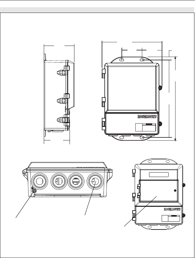
Figure 1. Rosemount 8712 Dimensional Drawing
4.31
(109)
LOI Keypad
Cover
9.01
(229)
11.15
(283)
2.81
(71) 3.11
(79)
12.02
(305)
0.44
(11)
Ground Lug
1/2–14 NPT
Conduit
Connection
(4 Places)
WITH STANDARD COVER
NOTE
Dimensions are in inches (millimeters)
2.96
(75) WITH LOI COVER
4664RevBBQIG.fm Page 4 Friday, January 11, 2013 6:13 PM

Quick Installation Guide
00825-0100-4664, Rev BB
January 2013 Rosemount 8712 / 8700 Series
5
Environmental Considerations
To ensure maximum transmitter life, avoid excessive heat and vibration. Typical problem
areas include:
• Warm-climate installations in direct sunlight
• Outdoor installations in cold climates
Remote mounted transmitters may be installed in the control room to protect the electronics
from the harsh environment and provide easy access for configuration or service.
Remotely mounted Rosemount 8712 transmitters require external power so there must be
access to a suitable power source.
Installation Procedures
Rosemount 8712 installation includes both detailed mechanical and electrical installation
procedures.
Mount the Transmitter
At a remote site the transmitter may be mounted on a pipe up to two inches in diameter or
against a flat surface.
Pipe Mounting
To mount the transmitter on a pipe:
1. Attach the mounting plate to the pipe using the mounting hardware.
2. Attach the 8712 to the mounting plate using the mounting screws.
Identify Options and Configurations
The standard application of the 8712 includes a 4–20 mA output and control of the sensor
coils and electrodes. Other applications may require one or more of the following
configurations or options:
• Multidrop Communications
• Digital Output
• Digital Input
• Pulse Output
Additional options may apply. Be sure to identify those options and configurations that apply
to your situation, and keep a list of them nearby for consideration during the installation and
configuration procedures.
Hardware Jumpers/Switches
The 8712 electronics board is equipped with three user-selectable hardware switches.
These switches set the Failure Alarm Mode, Internal/External Analog Power, and
Transmitter Security. The standard configuration for these switches when shipped from the
factory are as follows:
Changing Hardware Switch Settings
In most cases, it is not necessary to change the setting of the hardware switches. If you
need to change the switch settings, complete the steps outlined in the manual.
Failure Alarm Mode: HIGH
Internal/External Analog Power: INTERNAL
Transmitter Security: OFF
4664RevBBQIG.fm Page 5 Friday, January 11, 2013 6:13 PM
Quick Installation Guide
00825-0100-4664, Rev BB
January 2013
Rosemount 8712 / 8700 Series
6
Electrical Considerations
Before making any electrical connections to the Rosemount 8712, consider local and plant
electrical standards and be sure to have the proper power supply, conduit, and other
accessories necessary to comply with these standards.
STEP 2: HANDLING
Handle all parts carefully to prevent damage. Whenever possible, transport the system to
the installation site in the original shipping containers. PTFE-lined sensors are shipped with
end covers that protect it from both mechanical damage and normal unrestrained distortion.
Remove the end covers just before installation.
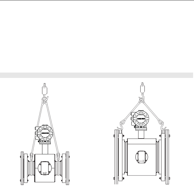
Figure 2. Rosemount 8705 Sensor Support for Handling
½- through 4-Inch Sensors
6-Inch and Larger Sensors
4664RevBBQIG.fm Page 6 Friday, January 11, 2013 6:13 PM
Quick Installation Guide
00825-0100-4664, Rev BB
January 2013 Rosemount 8712 / 8700 Series
7
STEP 3: MOUNTING
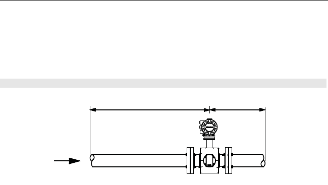
Upstream/Downstream Piping
To ensure specification accuracy over widely varying process conditions, install the sensor a
minimum of five straight pipe diameters upstream and two pipe diameters downstream from
the electrode plane (see Figure 3).
Installations with reduced straight runs from 0 to 5 pipe diameters are possible. In reduced
straight pipe run installations, performance will shift to as much as 0.5% of rate. Reported
flow rates will still be highly repeatable.
Flow Direction
The sensor should be mounted so the FORWARD end of the flow arrow, shown on the
sensor identification tag, points in the direction of flow through the sensor.
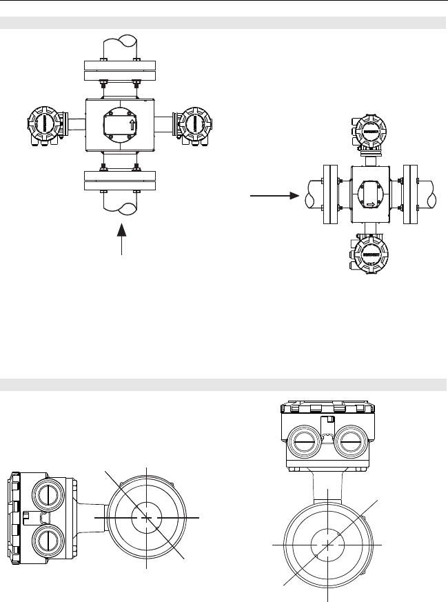
Sensor Orientation
The sensor should be installed in a position that ensures the sensor remains full during
operation. Vertical installation allows upward process fluid flow and keeps the
cross-sectional area full, regardless of flow rate. Horizontal installation should be restricted
to low piping sections that are normally full. In these cases, orient the electrode plane to
within 45° of horizontal.
Figure 3. Upstream and Downstream Straight Pipe Diameters
5 Pipe Diameters 2 Pipe Diameters
Flow
4664RevBBQIG.fm Page 7 Friday, January 11, 2013 6:13 PM
Quick Installation Guide
00825-0100-4664, Rev BB
January 2013
Rosemount 8712 / 8700 Series
8
The electrodes in the Rosemount 8705 sensor are properly orientated when the two
measurement electrodes are in the 3 and 9 o’clock positions, as shown on the right of
Figure 4.
The electrodes in the Rosemount 8711 are properly orientated when the top of the sensor is
either vertical or horizontal, as shown in Figure 5. Avoid any mounting orientation that
positions the top of the sensor at 45° from the vertical or horizontal position.
Figure 4. Sensor Orientation
Figure 5. Rosemount 8711 Mounting Position
FLOW
FLOW
45° Electrode Plane
45° Electrode Plane
4664RevBBQIG.fm Page 8 Friday, January 11, 2013 6:13 PM
Quick Installation Guide
00825-0100-4664, Rev BB
January 2013 Rosemount 8712 / 8700 Series
9
STEP 4: INSTALLATION
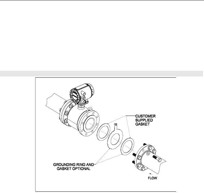
Flanged Sensors
Gaskets
The sensor requires a gasket at each of its connections to adjacent devices or piping. The gasket
material selected must be compatible with the process fluid and operating conditions. Metallic or
spiral-wound gaskets can damage the liner. Gaskets are required on each side of a
grounding ring. All other applications (including sensors with lining protectors or a grounding
electrode) require only one gasket on each end connection.
Flange Bolts
NOTE
Do not bolt one side at a time. Tighten each side simultaneously. Example:
1. Snug left
2. Snug right
3. Tighten left
4. Tighten right
Do not snug and tighten the upstream side and then snug and tighten the downstream side.
Failure to alternate between the upstream and downstream flanges when tightening bolts
may result in liner damage.
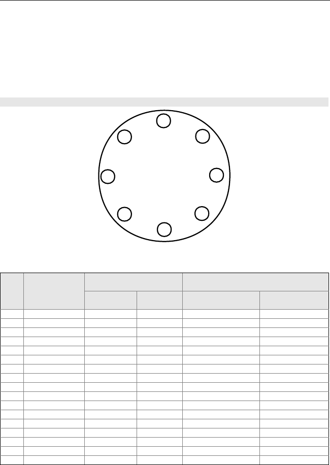
Suggested torque values by sensor line size and liner type are listed in Table 1 for ASME
B16.5 (ANSI) and Table 2 for DIN flanges. Consult the factory if the flange rating of the
sensor is not listed. Tighten flange bolts on the upstream side of the sensor in the
incremental sequence shown in Figure 7, to 20% of the suggested torque values. Repeat
the process on the downstream side of the sensor. For sensors with more or less flange
bolts, tighten the bolts in a similar crosswise sequence. Repeat this entire tightening
sequence at 40%, 60%, 80%, and 100% of the suggested torque values or until the leak
between the process and sensor flanges stop.
Figure 6. Flanged gasket placement
4664RevBBQIG.fm Page 9 Friday, January 11, 2013 6:13 PM
Quick Installation Guide
00825-0100-4664, Rev BB
January 2013
Rosemount 8712 / 8700 Series
10
If leakage has not stopped at the suggested torque values, the bolts can be tightened in
additional 10% increments until the joint stops leaking, or until the measured torque value
reaches the maximum torque value of the bolts. Practical consideration for the integrity of
the liner often leads the user to distinct torque values to stop leakage due to the unique
combinations of flanges, bolts, gaskets, and sensor liner material.
Check for leaks at the flanges after tightening the bolts. Failure to use the correct tightening
methods can result in severe damage. Sensors require a second tightening 24 hours after
the initial installation. Over time, sensor liner materials may deform under pressure.
Table 1. Suggested Flange Bolt Torque Values for Rosemount 8705 and 8707 High-Signal Sensors
Figure 7. Flange Bolt Torquing Sequence
Size
Code Line Size
PTFE/ETFE/PFA
liners Polyurethane/Neoprene/Linatex/Adiprene
liner
Class 150
(pound-feet) Class 300
(pound-feet) Class 150
(pound-feet) Class 300
(pound-feet)
005 0.5 inch (15 mm) 8 8 - -
010 1 inch (25 mm) 812 - -
015 1.5 inch (40 mm) 13 25 718
020 2 inch (50 mm) 19 17 14 11
030 3 inch (80 mm) 34 35 23 23
040 4 inch (100 mm) 26 50 17 32
060 6 inch (150mm) 45 50 30 37
080 8 inch (200 mm) 60 82 42 55
100 10 inch (250 mm) 55 80 40 70
120 12 inch (300 mm) 65 125 55 105
140 14 inch (350 mm) 85 110 70 95
160 16 inch (400 mm) 85 160 65 140
180 18 inch (450 mm) 120 170 95 150
200 20 inch (500 mm) 110 175 90 150
240 24 inch (600 mm) 165 280 140 250
300 30 inch (750 mm) 195 415 165 375
360 36 inch (900 mm) 280 575 245 525
15
3
7
8
4
62
8-bolt
4664RevBBQIG.fm Page 10 Friday, January 11, 2013 6:13 PM

Quick Installation Guide
00825-0100-4664, Rev BB
January 2013 Rosemount 8712 / 8700 Series
11
Table 2. Flange Bolt Torque and Bolt Load Specifications for 8705(EN 1092-1)
Size
Code Line Size
PTFE/ETFE liner
PN10 PN 16 PN 25 PN 40
(Newton-
meter) (Newton) (Newton-
meter) (Newton) (Newton-
meter) (Newton) (Newton-
meter) (Newton)
005 0.5-inch
(15 mm) 10 4400
010 1 inch
(25 mm) 20 10100
015 1.5 inch
(40 mm) 50 16100
020 2 inch
(50 mm) 60 20100
030 3 inch
(80 mm) 50 16800
040 4 inch
(100 mm) 50 17800 70 19600
060 6 inch
(150mm) 90 24700 130 28700
080 8 inch
(200 mm) 130 35200 90 19700 130 29200 170 34400
100 10 inch
(250 mm) 100 28000 130 28300 190 38000 250 44800
120 12 inch
(300 mm) 120 32000 170 38400 190 38600 270 47700
140 14 inch
(350 mm) 160 43800 220 49500 320 57200 410 68100
160 16 inch
(400 mm) 220 50600 280 56200 410 68100 610 92900
180 18 inch
(450 mm) 190 43200 340 68400 330 55100 420 64000
200 20 inch
(500 mm) 230 51100 380 68900 440 73300 520 73900
240 24 inch
(600 mm) 290 58600 570 93600 590 90100 850 112000
4664RevBBQIG.fm Page 11 Friday, January 11, 2013 6:13 PM

Quick Installation Guide
00825-0100-4664, Rev BB
January 2013
Rosemount 8712 / 8700 Series
12
Table 2. (continued) Flange Bolt Torque and Bolt Load Specifications for 8705 (EN 1092-1)
Size
Code Line Size
Polyurethane, Linatex, Adiprene and Neoprene Liners
PN 10 PN 16 PN 25 PN 40
(Newton-
meter) (Newton) (Newton-
meter) (Newton) (Newton-
meter) (Newton) (Newton-
meter) (Newton)
010 1 inch
(25 mm) 20 7040
015 1.5 inch
(40 mm) 30 10700
020 2 inch
(50 mm) 40 13400
030 3 inch
(80 mm) 30 11100
040 4 inch
(100 mm) 40 11700 50 13200
060 6 inch
(150mm) 60 16400 90 19200
080 8 inch
(200 mm) 90 23400 60 13100 90 19400 110 22800
100 10 inch
(250 mm) 70 18600 80 18800 130 25400 170 29900
120 12 inch
(300 mm) 80 21300 110 25500 130 25800 180 31900
140 14 inch
(350 mm) 110 29100 150 33000 210 38200 280 45400
160 16 inch
(400 mm) 150 33700 190 37400 280 45400 410 62000
180 18 inch
(450 mm) 130 28700 230 45600 220 36800 280 42700
200 20 inch
(500 mm) 150 34100 260 45900 300 48800 350 49400
240 24 inch
(600 mm) 200 39200 380 62400 390 60100 560 74400
4664RevBBQIG.fm Page 12 Friday, January 11, 2013 6:13 PM
Quick Installation Guide
00825-0100-4664, Rev BB
January 2013 Rosemount 8712 / 8700 Series
13
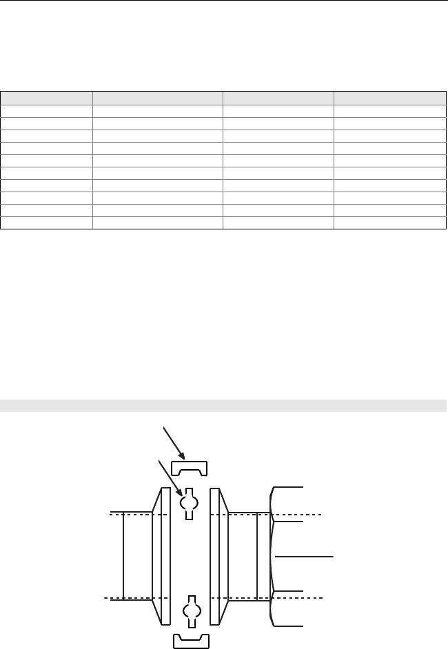
Wafer Sensors
Gaskets
The sensor requires a gasket at each of its connections to adjacent devices or piping. The gasket
material selected must be compatible with the process fluid and operating conditions. Metallic or
spiral-wound gaskets can damage the liner. Gaskets are required on each side of a
grounding ring. See Figure 8 below.
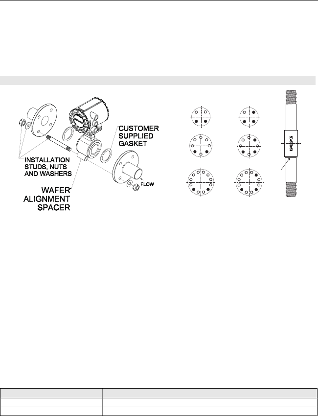
Alignment
1. On 1.5 through 8-inch (40 through 200 mm) line sizes. Rosemount strongly recommends
installing the alignment spacers provided to insure proper centering of the wafer sensor
between the process flanges. Sensor sizes of 0.15, 0.30, 0.5 and 1 in. (4 through 25
mm), do not require alignment spacers.
2. Insert studs for the bottom side of the sensor between the pipe flanges and center the
alignment spacer in the middle of the stud. See Figure 8 for the bolt hole locations
recommended for the spacers provided. Stud specifications are listed in Table 3.
3. Place the sensor between the flanges. Make sure that the alignment spacers are
properly centered on the studs. For vertical flow installations slide the oring over the stud
to keep the spacer in place. See Figure 8. To ensure the spacers match the flange size
and class rating for the process flanges see Table 4.
4. Insert the remaining studs, washers, and nuts.
5. Tighten to the torque specifications shown in Table 5. Do not overtighten the bolts or the
liner may be damaged.
NOTE
Sensor sizes of 0.15, 0.30, and 0.5 in. mount between AMSE 1/2-inch flanges. Using carbon
steel bolts on sensor sizes of 0.15, 0.30, 0.5 and 1 in. (15 and 25 mm), rather than the
required stainless steel bolts, will degrade the flow sensor measurement.
Figure 8. Wafer gasket placement
Table 3. Stud Specifications
Nominal Sensor Size Stud Specifications
0.15 – 1 inch (4 – 25 mm) 316 SST ASTM A193, Grade B8M Class 1 threaded mounted studs
1.5 – 8 inch (40 – 200 mm) CS, ASTM A193, Grade B7, threaded mounting studs
Spacer Installation
Horizontal meters Vertical meters
O-ring
4664RevBBQIG.fm Page 13 Friday, January 11, 2013 6:13 PM

Quick Installation Guide
00825-0100-4664, Rev BB
January 2013
Rosemount 8712 / 8700 Series
14
Table 4. Rosemount Alignment Spacer Table
To order an Alignment Spacer Kit (qty 3 spacers) use p/n 08711-3211-xxxx along with the
Dash No. above.
Rosemount Alignment Spacer Table
Dash No.
Line Size
Flange Rating(in) (mm)
0A15 1.5 40 JIS 10K-20K
0A20 250 JIS 10K-20K
0A30 380 JIS 10K
0B15 1.5 40 JIS 40K
AA15 1.5 40 ANSI - 150#
AA20 250 ANSI - 150#
AA30 380 ANSI - 150#
AA40 4100 ANSI - 150#
AA60 6150 ANSI - 150#
AA80 8200 ANSI - 150#
AB15 1.5 40 ANSI - 300#
AB20 250 ANSI - 300#
AB30 380 ANSI - 300#
AB40 4100 ANSI - 300#
AB60 6150 ANSI - 300#
AB80 8200 ANSI - 300#
AB15 1.5 40 ANSI - 300#
AB20 250 ANSI - 300#
AB30 380 ANSI - 300#
AB40 4100 ANSI - 300#
AB60 6150 ANSI - 300#
AB80 8200 ANSI - 300#
DB40 4100 DIN - PN10/16
DB60 6150 DIN - PN10/16
DB80 8200 DIN - PN10/16
DC80 8100 DIN - PN25
DD15 1.5 150 DIN - PN10/16/25/40
DD20 250 DIN - PN10/16/25/40
DD30 380 DIN - PN10/16/25/40
DD40 4100 DIN - PN25/40
DD60 6150 DIN - PN25/40
DD80 8200 DIN - PN40
RA80 8200 AS40871-PN16
RC20 250 AS40871-PN21/35
RC30 380 AS40871-PN21/35
RC40 4100 AS40871-PN21/35
RC60 6150 AS40871-PN21/35
RC80 8200 AS40871-PN21/35
4664RevBBQIG.fm Page 14 Friday, January 11, 2013 6:13 PM
Quick Installation Guide
00825-0100-4664, Rev BB
January 2013 Rosemount 8712 / 8700 Series
15
Flange Bolts
Wafer sensors require threaded studs. See Figure 7 for torque sequence. Always check for
leaks at the flanges after tightening the flange bolts. All sensors require a second torquing
24 hours after initial flange bolt tightening.
Sanitary Sensors
Gaskets
The sensor requires a gasket at each of its connections to adjacent devices or piping. The
gasket material selected must be compatible with the process fluid and operating conditions.
Gaskets are supplied between the IDF fitting and the process connection fitting, such as a
Tri-Clamp fitting, on all Rosemount 8721 Sanitary sensors except when the process
connection fittings are not supplied and the only connection type is an IDF fitting.
Alignment and Bolting
Standard plant practices should be followed when installing a magmeter with sanitary
fittings. Unique torque values and bolting techniques are not required.
Table 5. Rosemount 8711 Torque Specifications
Size Code Line Size Pound-feet Newton-meter
15F 0.15 inch (4 mm) 5 7
30F 0.30 inch (8 mm) 5 7
005 0.5 inch (15 mm) 5 7
010 1 inch (25 mm) 10 14
015 1.5 inch (40 mm) 15 20
020 2 inch (50 mm) 25 34
030 3 inch (80 mm) 40 54
040 4 inch (100 mm) 30 41
060 6 inch (150 mm) 50 68
080 8 inch (200 mm) 70 95
Figure 9. Rosemount 8721 Sanitary Installation
User supplied clamp
User supplied gasket
4664RevBBQIG.fm Page 15 Friday, January 11, 2013 6:13 PM
Quick Installation Guide
00825-0100-4664, Rev BB
January 2013
Rosemount 8712 / 8700 Series
16
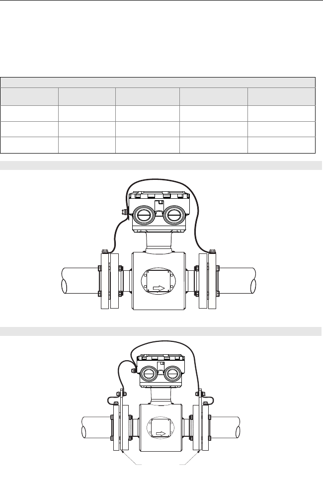
STEP 5: GROUNDING
Use Table 6 to determine which process grounding option to follow for proper installation.
The sensor case should be earth grounded in accordance with national and local electrical
codes. Failure to do so may impair the protection provided by the equipment.
Table 6. Process Grounding Installation
Process Grounding Options
Type of Pipe Grounding
Straps Grounding
Rings Grounding
Electrode Lining
Protectors
Conductive
Unlined Pipe See Figure 10 Not Required Not Required See Figure 11
Conductive Lined
Pipe Insufficient
Grounding See Figure 11 See Figure 10 See Figure 11
Non-Conductive
Pipe Insufficient
Grounding See Figure 12 See Figure 13 See Figure 12
Figure 10. Grounding Straps or Grounding Electrode in Lined Pipe
Figure 11. Grounding with Grounding Rings or Lining Protectors
Grounding Rings or Lining
Protectors
4664RevBBQIG.fm Page 16 Friday, January 11, 2013 6:13 PM
Quick Installation Guide
00825-0100-4664, Rev BB
January 2013 Rosemount 8712 / 8700 Series
17
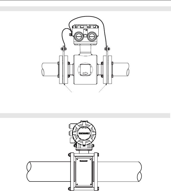
Figure 12. Grounding with Grounding Rings or Lining Protectors
Figure 13. Grounding with Grounding Electrode
Grounding Rings or Lining
Protectors
4664RevBBQIG.fm Page 17 Friday, January 11, 2013 6:13 PM
Quick Installation Guide
00825-0100-4664, Rev BB
January 2013
Rosemount 8712 / 8700 Series
18
STEP 6: WIRING
Conduit Ports and Connections
This wiring section covers the connection between the transmitter and sensor, the 4-20 mA
loop, and supplying power to the transmitter. Follow the conduit information, cable
requirements, and disconnect requirements in the sections below.
Conduit Ports and Connections
Both the sensor and transmitter junction boxes have ports for 1/2-inch NPT conduit
connections with optional CM20 or PG 13.5 connections available. These connections
should be made in accordance with national, local, and plant electrical codes. Unused ports
should be sealed with metal plugs. Proper electrical installation is necessary to prevent
errors due to electrical noise and interference. Separate conduits are not necessary for the
coil drive and signal cables, but a dedicated conduit line between each transmitter and
sensor is required. Shielded cable must be used for best results in electrically noisy
environments. When preparing all wire connections, remove only the insulation required to
fit the wire completely under the terminal connection. Removal of excessive insulation may
result in an unwanted electrical short to the transmitter housing or other wire connections.
For flanged sensors installed into an application requiring IP68 protection, sealed cable
glands, conduit, and conduit plugs that meet IP68 ratings are required.
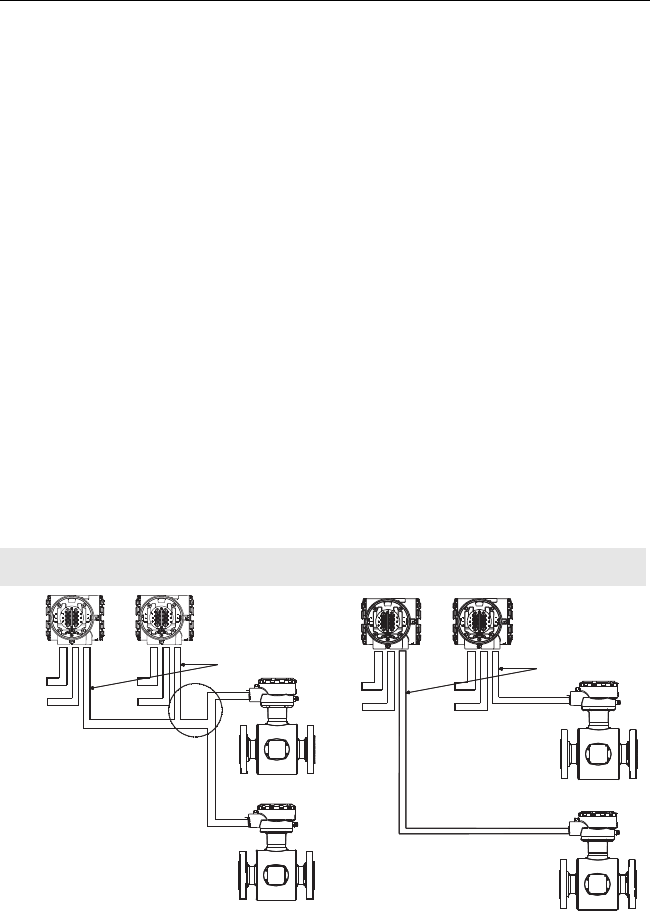
Conduit Requirements
A single dedicated conduit run for the coil drive and signal cable is needed between the
sensor and the remote transmitter. See Figure 14. Bundled cables in a single conduit are
likely to create interference and noise problems in the system. Use one set of cables per
conduit run.
Figure 14. Conduit Preparation
Wrong Correct
Coil Drive
and
Electrode
Cables
Power
Outputs
Power
Outputs
Coil Drive
and
Electrode
Cables
Power
Outputs
Power
Outputs
4664RevBBQIG.fm Page 18 Friday, January 11, 2013 6:13 PM
Quick Installation Guide
00825-0100-4664, Rev BB
January 2013 Rosemount 8712 / 8700 Series
19
Run the appropriate size cable through the conduit connections in your magnetic flowmeter
system. Run the power cable from the power source to the transmitter. Run the coil drive
and signal cables between the flowmeter sensor and transmitter.
• Installed signal wiring should not be run together and should not be in the same cable
tray as AC or DC power wiring.
• Device must be properly grounded or earthed according to local electric codes.
• Rosemount combination cable part number 08732-0753-1003 (ft) or 08732-0753-2004
(m) is required to be used to meet EMC requirements.
Transmitter to Sensor Wiring
The transmitter can be integral to the sensor or remotely mounted following the wiring
instructions.
Remote Mount Cable Requirements and Preparation
For installations using the individual coil drive and signal cable, lengths should be limited to
less than 1,000 feet (300 meters). Equal length cable is required for each. See Table 7.
For installations using the combination coil drive and signal cable, lengths should be limited
to less than 330 feet (100 meters). See Table 7.
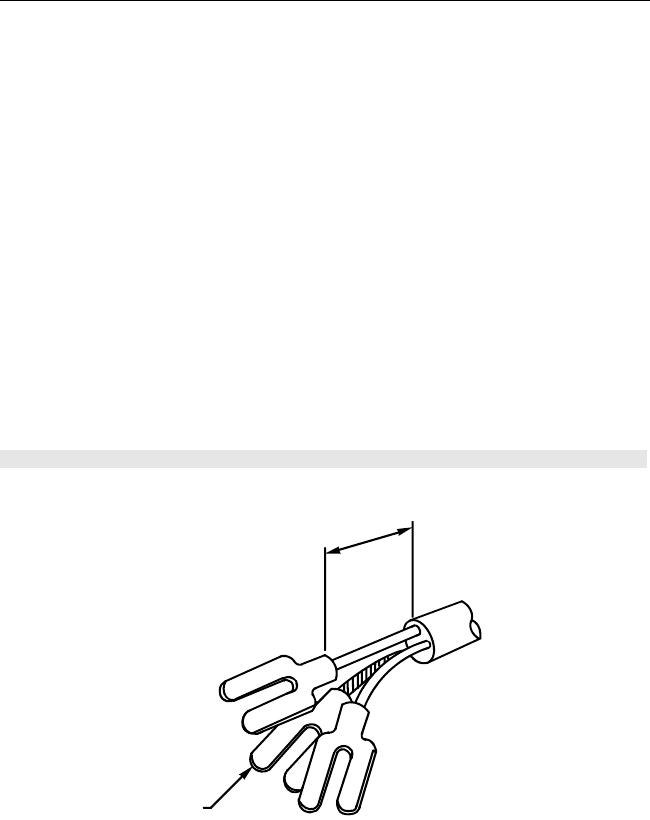
Prepare the ends of the coil drive and signal cables as shown in Figure 15. Limit the
unshielded wire length to 1-inch on both the coil drive and signal cables. Any unsheathed
wire should be wrapped with proper insulation. Excessive lead length or failure to connect
cable shields can create electrical noise resulting in unstable meter readings.
Figure 15. Cable Preparation Detail
Cable Shield
1.00
(26)
NOTE
Dimensions are in inches (millimeters).
4664RevBBQIG.fm Page 19 Friday, January 11, 2013 6:13 PM
Quick Installation Guide
00825-0100-4664, Rev BB
January 2013
Rosemount 8712 / 8700 Series
20
STEP 6 CONTINUED...
To order cable specify length as quantity desired.
25 feet = Qty (25) 08732-0753-1003
Table 7. Cable Requirements
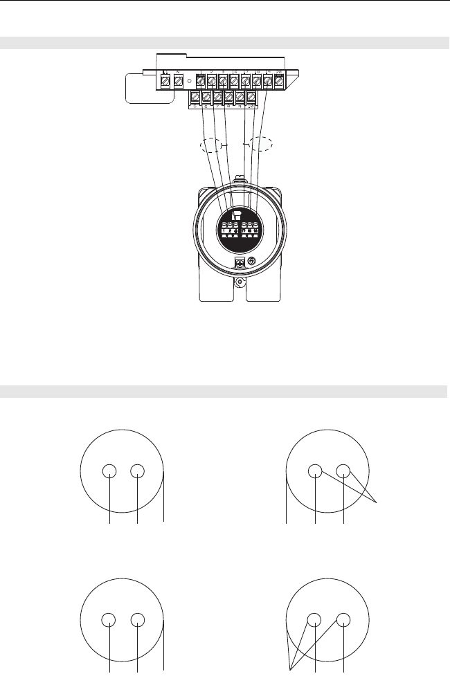
Wiring the Transmitter to the Sensor
When using individual cables for coil drive and signal refer to Table 8. If using the
combination coil drive and signal cable, refer to Table 9. See Figure 16 for transmitter
specific wiring diagram.
1. Connect the coil drive cable using terminals 1, 2, and 3 (ground).
2. Connect the signal cable using terminals 17, 18, and 19.
Table 8. Individual Coil and Signal Cables
Table 9. Combination Coil and Signal Cable
Description Length Part Number
Coil Drive Cable (14 AWG)
Belden 8720, Alpha 2442
or equivalent
ft
m08712-0060-0001
08712-0060-2013
Signal Cable (20 AWG)
Belden 8762, Alpha 2411
or equivalent
ft
m08712-0061-0001
08712-0061-2003
Combination Cable
Coil Drive Cable (18 AWG) and
Signal Cable (20 AWG)
ft
m08732-0753-1003
08732-0753-2004
WARNING
Potential Shock Hazard Across Terminals 1 & 2 (40 Vac).
Transmitter Terminal Sensor Terminal Wire Gauge Wire Color
1 1 14 Clear
2 2 14 Black
3 or Ground 3 or Ground 14 Shield
17 17 20 Shield
18 18 20 Black
19 19 20 Clear
Transmitter Terminal Sensor Terminal Wire Gauge Wire Color
1 1 18 Red
2 2 18 Green
3 or Ground 3 or Ground 18 Shield
17 17 20 Shield
18 18 20 Black
19 19 20 White
4664RevBBQIG.fm Page 20 Friday, January 11, 2013 6:13 PM
Quick Installation Guide
00825-0100-4664, Rev BB
January 2013 Rosemount 8712 / 8700 Series
21
STEP 6 CONTINUED...
NOTE
When using the Rosemount supplied combination cable, the signal wires for terminals 18
and 19 contain an additional shield wire. These two shield wires should be tied with the main
shield wire at terminal 17 at the sensor terminal block and cut back to the insulation in the
transmitter junction box. See Figure 17.
Figure 16. Remote Mount Wiring Diagrams
Figure 17. Combination Coil and Signal Cable Wiring Diagram
Transsmiter
Tube
Coil Drive Cable
1 Red 2 Green 3 Shield 17 Shield 18 Black 19 White
Cut Shield
Signal Cable
17 Shield 18 Black 19 White1 Red 2 Green 3 Shield
4664RevBBQIG.fm Page 21 Friday, January 11, 2013 6:13 PM
Quick Installation Guide
00825-0100-4664, Rev BB
January 2013
Rosemount 8712 / 8700 Series
22
STEP 6 CONTINUED...
Connect the 4–20 mA Analog Signal
Cabling considerations
If possible, use individually shielded twisted pair cable, either in single pair or multi-pair
varieties. Unshielded cables may be used for short distances, provided ambient noise and
cross-talk will not adversely impact communication. The minimum conductor size is 0.51 mm
diameter (#24 AWG) for cable runs less than 1,500 meters (@ 5,000 ft.) and 0.81 mm
diameter (#20 AWG) for longer distances. Resistance in the loop must be 1000 ohms or less.
The 4–20 mA analog output loop signal may be powered internally or externally. The default
position of the internal/external analog power switch is in the internal position. The
user-selectable power supply switch is located on the electronics board.
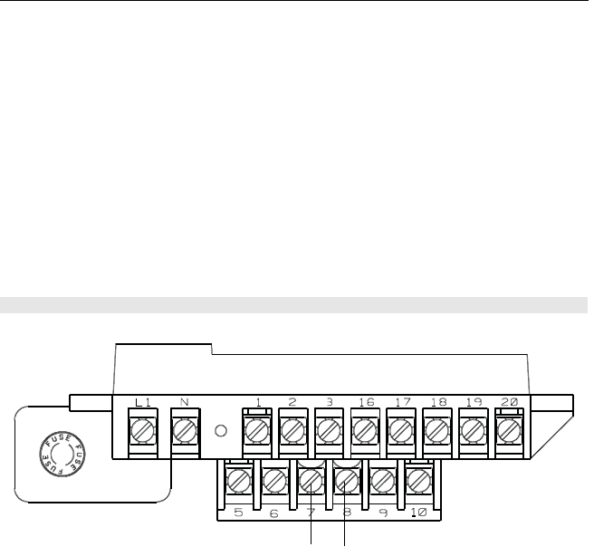
8712E - connect negative (-)DC to Terminal 8 and positive (+)DC to Terminal 7. See
Figure 18.
Internal Power Source
The 4–20 mA analog signal loop is powered from the transmitter itself.
External Power Source
The 4–20 mA analog signal loop is powered from an external power source. HART multidrop
installations require a 10–30 V DC external analog power source.
NOTE:
If a HART Field Communicator or control system will be used, it must be connected across a
minimum of 250 ohms resistance in the loop.
To connect any of the other output options (pulse output and/or digital input/output), consult
the comprehensive product manual.
Figure 18. 8712E Analog Signal Wiring Diagram
–4–20 mA
+4–20 mA
4664RevBBQIG.fm Page 22 Friday, January 11, 2013 6:13 PM
Quick Installation Guide
00825-0100-4664, Rev BB
January 2013 Rosemount 8712 / 8700 Series
23
Powering the Transmitter
The 8712E transmitter is designed to be powered by 90-250 Vac, 50–60 Hz or 12–42 Vdc.
Before connecting power to the Rosemount 8712E consider the following standards and be
sure to have the proper power supply, conduit, and other accessories. Wire the transmitter
according to national, local and plant electrical requirements for the supply voltage. See
Figure 19.
Supply Wire Requirements
Use 12 to 18 AWG wire rated for the proper temperature of the application. For connections
in ambient temperatures above 140 °F (60 °C), use a wire rated for 176 °F (80 °C). For
ambient temperatures greater than 176 °F (80 °C), use a wire rated for 230 °F (110 °C). For
DC powered transmitters with extended cable lengths, verify that there is a minimum of 12 V
DC at the terminals of the transmitter.
Disconnects
Connect the device through an external disconnect or circuit breaker. Clearly label the
disconnect or circuit breaker and locate it near the transmitter and per local electrical
control.
Installation Category
The installation category for the 8712E is (Overvoltage) Category II.
Overcurrent Protection
The Rosemount 8712E transmitter requires overcurrent protection of the supply lines.
Maximum ratings of overcurrent devices are shown in Table 10.
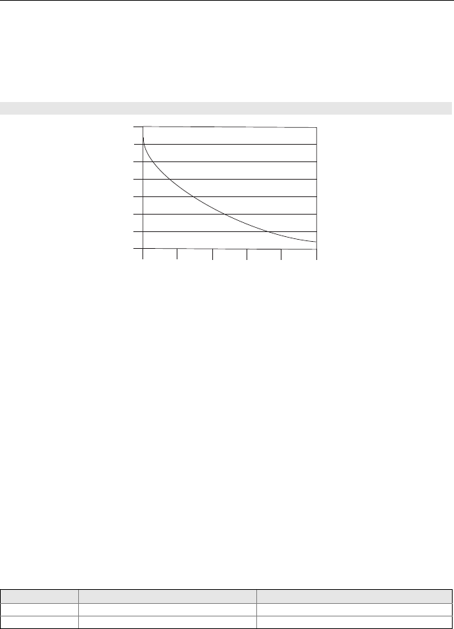
Figure 19. DC Power Supply Current Requirements
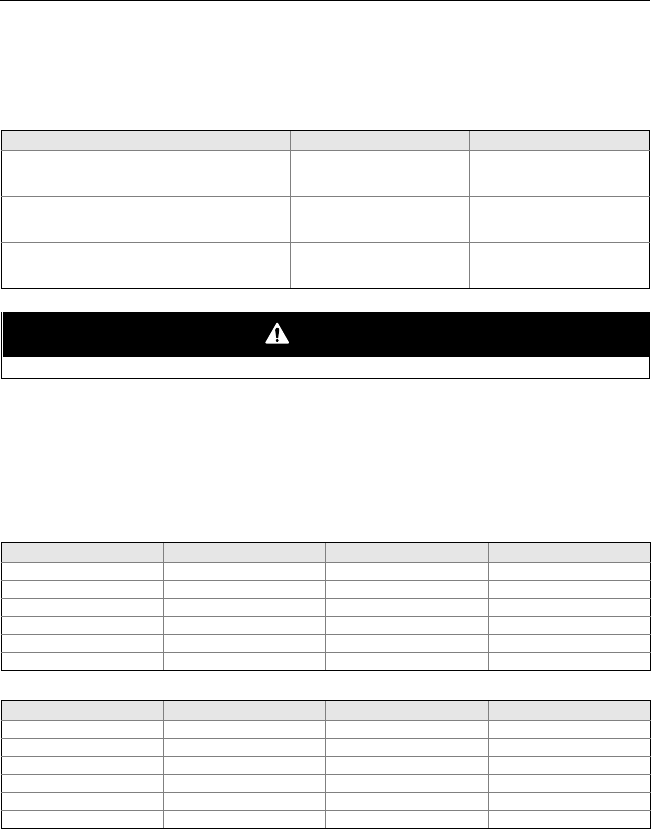
Table 10. Overcurrent Limits
Power System Fuse Rating Manufacturer
95-250 V AC 2 Amp, Quick Acting Bussman AGC2 or Equivalent
12-42 V DC 3 Amp, Quick Acting Bussman AGC3 or Equivalent
12 18 24 30 36 42
0.2
0.3
0.4
0.5
0.6
0.7
0.8
0.9
Power Supply (Volts)
I = Supply current requirement (Amps)
V = Power supply voltage (Volts)
Supply Current (Amps)
4664RevBBQIG.fm Page 23 Friday, January 11, 2013 6:13 PM
Quick Installation Guide
00825-0100-4664, Rev BB
January 2013
Rosemount 8712 / 8700 Series
24
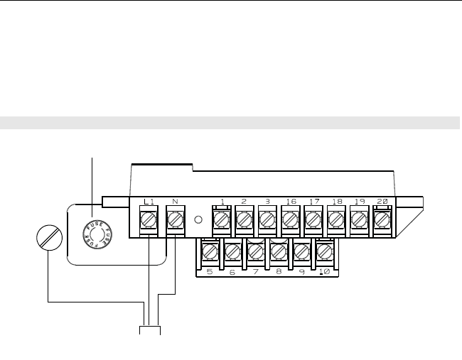
8712E Power Supply
For AC power applications (90-250 VAC, 50-60 Hz) connect AC Neutral to terminal N and
connect AC Line to terminal L1. For DC power applications, connect negative to terminal N
(DC -) and positive to terminal L1 (DC +). Ground the transmitter cage via the grounding
stud located on the bottom of the transmitter housing. Units powered by 12-42 V DC
powersupply may draw up to 1 amp of current. See Figure 20 for terminal block
connections.
Figure 20. 8712E Transmitter Power Connections
Transmitter
Power Cable
AC Neutral or DC–
AC Line or DC+
AC Ground or
DC Ground
Fuse
4664RevBBQIG.fm Page 24 Friday, January 11, 2013 6:13 PM

Quick Installation Guide
00825-0100-4664, Rev BB
January 2013 Rosemount 8712 / 8700 Series
25
Step 7: Basic Configuration
Once the magnetic flowmeter is installed and power has been supplied, the transmitter must
be configured through the basic setup. These parameters can be configured through either
a local operator interface or a HART communication device. A table of all the parameters
are on page 26. Descriptions of the more advanced functions are included in the
comprehensive product manual.
Basic Setup
Tag
Tag is the quickest and shortest way of identifying and distinguishing between transmitters.
Transmitters can be tagged according to the requirements of your application. The tag may
be up to eight characters long.
Flow Rate Units
The flow rate units variable specifies the format in which the flow rate will be displayed. Units
should be selected to meet your particular metering needs.
Line Size
The line size (sensor size) must be set to match the actual sensor connected to the
transmitter. The size must be specified in inches.
URV (Upper Range Value)
The upper range value (URV) sets the 20 mA point for the analog output. This value is
typically set to full-scale flow. The units that appear will be the same as those selected under
the units parameter. The URV may be set between –39.3 ft/s to 39.3 ft/s
(–12 m/s to 12 m/s). There must be at least 1 ft/s (0.3 m/s) span between the URV and LRV.
LRV (Lower Range Value)
The lower range value (LRV) sets the 4 mA point for the analog output. This value is
typically set to zero flow. The units that appear will be the same as those selected under the
units parameter. The LRV may be set between –39.3 ft/s to 39.3 ft/s (–12 m/s to 12 m/s).
There must be at least 1 ft/s (0.3 m/s) span between the URV and LRV.
Calibration Number
The sensor calibration number is a 16-digit number used to identify sensors calibrated at the
Rosemount factory.
4664RevBBQIG.fm Page 25 Friday, January 11, 2013 6:13 PM

Quick Installation Guide
00825-0100-4664, Rev BB
January 2013
Rosemount 8712 / 8700 Series
26
Table 11. Field Communicator Fast Key Sequence
Local Operator Interface
The optional Local Operator Interface (LOI) provides an operator communications center for
the 8712E. By using the LOI, the operator can access any transmitter function for changing
configuration parameter settings, checking totalized values, or other functions. The LOI is
integral to the transmitter housing.
Function Fast Keys
Process Variables (PV) 1,1
Primary Variable Value 1,1,1
Primary Variable% 1,1,2
PV Loop Current 1,1,3
Totalizer Set-Up 1,1,4
Totalizer Units 1,1,4,1
Gross Total 1,1,4,2
Net Total 1,1,4,3
Reverse Total 1,1,4,4
Start Totalizer 1,1,4,5
Stop Totalizer 1,1,4,6
Reset Totalizer 1,1,4,7
Pulse Output 1,1,5
Basic Setup 1,3
Tag 1,3,1
Flow Units 1,3,2
PV Units 1,3,2,1
Special Units 1,3,2,2
Volume Unit 1,3,2,2,1
Base Volume Unit 1,3,2,2,2
Conversion Number 1,3,2,2,3
Base Time Unit 1,3,2,2,4
Flow Rate Unit 1,3,2,2,5
Line Size 1,3,3
PV URV 1,3,4
PV LRV 1,3,5
Calibration Number 1,3,6
PV Damping 1,3,7
Review 1,5
4664RevBBQIG.fm Page 26 Friday, January 11, 2013 6:13 PM

Quick Installation Guide
00825-0100-4664, Rev BB
January 2013 Rosemount 8712 / 8700 Series
27
PRODUCT CERTIFICATIONS
Approved Manufacturing Locations
Rosemount Inc. — Eden Prairie, Minnesota, USA
Fisher-Rosemount Technologias de Flujo, S.A. de C.V. — Chihuahua Mexico
Emerson Process Management Flow — Ede, The Netherlands
Asia Flow Technology Center — Nanjing, China
European Directive Information
The EC declaration of conformity can be found on page 31. The most recent revision can be found
at www.rosemount.com.
Type n protection type in accordance with EN 50021
• Closing of entries in the device must be carried out using the appropriate EExe or EExn
metal cable gland and metal blanking plug or any appropriate ATEX approved cable
gland and blanking plug with IP66 rating certified by an EU approved certification body.
CE Marking
Complies with EN 61326-1: 2006
Complies with Essential Health and Safety Requirements:
EN 60079-15: 2003
International Certificates
C-Tick Marking
Rosemount Inc. complies with the following IEC Requirements:
IEC 60079-0: 2004
IEC 60079-15: 2005-03
Hazardous Locations Certifications
North American Certifications
Factory Mutual (FM)
N0 Non-incendive for Class I, Division 2
Groups A, B, C, and D non-flammable fluids
(T4 at 40 °C)
Dust-ignition proof Class II/III, Division 1
Groups E, F, and G
(T4 at 40 °C)
Hazardous Locations; Enclosure Type 4X, IP66
N5 Non-incendive for Class I, Division 2,
Groups A, B, C, and D flammable fluids
(T4 at 40 °C)
Dust-ignition proof Class II/III, Division 1
Groups E, F, and G
(T4 at 40 °C)
Hazardous Locations; Enclosure Type 4X, IP66
Requires sensors with N5 Approval
4664RevBBQIG.fm Page 27 Friday, January 11, 2013 6:13 PM

Quick Installation Guide
00825-0100-4664, Rev BB
January 2013
Rosemount 8712 / 8700 Series
28
Canadian Standards Association (CSA)
N0 Non-incendive for Class I, Division 2
Groups A, B, C, and D non-flammable fluids
(T4 at 40 °C)
Dust-ignition proof Class II/III, Division 1
Groups E, F, and G
(T4 at 40 °C)
Hazardous Locations; Enclosure Type 4X
European Certifications
N1 ATEX Type n
Certificate No: Baseefa 05ATEX0170X
II 3G EEx nA nL IIC T4 (-40 °C Ta +60 °C)
Vmax = 42 V DC
IP 66
0575
Special Conditions for Safe Use (x)
The apparatus is not capable of withstanding the 500V electrical strength test required
by Clause 8.1of EN 60079-15: 2003. This must be taken into account when installing
the apparatus.
International Certifications
IECEx
N7 IECEx Type n
Certificate No: IECEx BAS 07.0036X
Ex nA nL IIC T4 (Ta = -40 °C to + 60 °C)
Vmax = 42 V DC
Special Conditions for Safe Use (x)
The apparatus is not capable of withstanding the 500V electrical strength required by
Clause 6.8.1of IEC 60079-15: 2005. This must be taken into account when installing
the apparatus.
InMetro - Brazil
N2 Non-incendive, Type n
Certificate No: NCC 11.0198X
Ex nA ic IIC T4 Gc (-40 °C Ta +60 °C)
Vmax = 42 V DC
4664RevBBQIG.fm Page 28 Friday, January 11, 2013 6:13 PM

Quick Installation Guide
00825-0100-4664, Rev BB
January 2013 Rosemount 8712 / 8700 Series
29
Sensor Approval Information
Approval
Codes
Rosemount 8705 Sensor Rosemount 8707 Sensor Rosemount 8711 Sensor Rosemount 8721
Sensors
For
Non-flammable
Fluids
For
Flammable
Fluids
For
Non-flammable
Fluids
For
Flammable
Fluids
For
Non-flammable
Fluids
For
Flammable
Fluids
For
Non-flammable
Fluids
NA • •
N0 • • •
ND • • •
N1 • • • •
N5 • • • • • •
N7 • • • •
NF • • •
E1 • • • •
E5(1)
(1) Available in line sizes up to 8 in. (200 mm) only.
•• • •
KD(2)
(2) Refer to Table 13 on page 30 for relation between ambient temperature, process temperature, and
temperature class.
•• • •
4664RevBBQIG.fm Page 29 Friday, January 11, 2013 6:13 PM

Quick Installation Guide
00825-0100-4664, Rev BB
January 2013
Rosemount 8712 / 8700 Series
30
Table 12. Electrical Data
Rosemount 8705 and 8711 Sensors
Coil excitation circuit: 40 V DC (pulsed), 0,5 A, 20 W maximum
Electrode circuit: in type of explosion protection intrinsic safety EEx ia IIC, Ui = 5 V, li = 0.2 mA,
Pi = 1 mW, Um = 250 V
Table 13. Relation between ambient temperature, process temperature, and temperature class(1)
(1) This table is applicable for KD approval codes only.
Meter Size (Inches) Maximum Ambient Temperature Maximum Process
Temperature Temperature
Class
1/2115 °F (65 °C) 239 °F (115 °C) T3
1149 °F (65 °C) 248 °F (120 °C) T3
195 °F (35 °C) 95 °F (35 °C) T4
11/2149 °F (65 °C) 257 °F (125 °C) T3
11/2122 °F (50 °C) 148 °F (60 °C) T4
2149 °F (65 °C) 257 °F (125 °C) T3
2149 °F (65 °C) 167 °F (75 °C) T4
2104 °F (40 °C) 104 °F (40 °C) T5
3 - 36 149 °F (65 °C) 266 °F (130 °C) T3
3 - 36 149 °F (65 °C) 194 °F (90 °C) T4
3 - 36 131 °F (55 °C) 131 °F (55 °C) T5
3 - 36 104 °F (40 °C) 104 °F (40 °C) T6
6115 °F (65 °C) 275 °F(135 °C) T3
6115 °F (65 °C) 230 °F (110 °C) T4
6115 °F (65 °C) 167 °F (75 °C) T5
6140 °F (60 °C) 140 °F (60 °C) T6
8-60 115 °F (65 °C) 284 °F (140 °C) T3
8-60 115 °F (65 °C) 239 °F (115 °C) T4
8-60 115 °F (65 °C) 176 °F (80 °C) T5
8-60 115 °F (65 °C) 145 °F (65 °C) T6
4664RevBBQIG.fm Page 30 Friday, January 11, 2013 6:13 PM

Quick Installation Guide
00825-0100-4664, Rev BB
January 2013 Rosemount 8712 / 8700 Series
31
Figure 21. Declaration of Conformity
EC Declaration of Conformity
No: RMD 1031 Rev. E
FILE ID: 8712 CE Marking Page 1 of 2 8712_RMD1031E.DOC
We,
Rosemount Inc.
12001 Technology Drive
Eden Prairie, MN 55344-3695
USA
declare under our sole responsibility that the product(s),
Model 8712D and Model 8712E Magnetic Flowmeter
Transmitters
manufactured by,
Rosemount Inc.
12001 Technology Drive and 8200 Market Boulevard
Eden Prairie, MN 55344-3695 Chanhassen, MN 55317-9687
USA USA
to which this declaration relates, is in conformity with the provisions of the European
Community Directives, including the latest amendments, as shown in the attached schedule.
Assumption of conformity is based on the application of the harmonized standards and, when
applicable or required, a European Community notified body certification, as shown in the
attached schedule.
Mark Fleigle February 09, 2009
Vice President Technology and New Products
(date of issue) (name - printed)
(function name - printed)
(signature)
4664RevBBQIG.fm Page 31 Friday, January 11, 2013 6:13 PM

Quick Installation Guide
00825-0100-4664, Rev BB
January 2013
Rosemount 8712 / 8700 Series
32
Schedule
EC Declaration of Conformity RMD 1031 Rev. E
FILE ID: 8712 CE Marking Page 2 of 2 8712_RMD1031E.DOC
LVD Directive (2006/95/EC)
All Models
EN 61010-1: 2001
EMC Directive (2004/108/EC)
All Models
EN 61326-1: 2006
ATEX Directive (94/9/EC)
Model 8712D with Power Supply Option 03 and option code N1
Model 8712E with Power Supply Option 2 and option code N1
Baseefa05ATEX0170X Type n Certificate
Equipment Group II, Category 3 G (EEx nA nL IIC T4)
EN 60079-15: 2003
ATEX Notified Bodies for EC Type Examination Certificate
Baseefa [Notified Body Number: 1180]
Rockhead Business Park, Staden Lane
Buxton, Derbyshire SK17 9RZ
United Kingdom
ATEX Notified Body for Quality Assurance
Det Norske Veritas (DNV) [Notified Body Number: 0575]
Veritasveien 1, N-1322
Hovik, Norway
4664RevBBQIG.fm Page 32 Friday, January 11, 2013 6:13 PM
