Emerson Alber Bds 40 User Guide Search Zz
2015-03-30
: Emerson Emerson-Alber-Bds-40-User-Guide-679614 emerson-alber-bds-40-user-guide-679614 emerson pdf
Open the PDF directly: View PDF ![]() .
.
Page Count: 205 [warning: Documents this large are best viewed by clicking the View PDF Link!]
- Table of Contents
- Table of Figures
- 1. Safety Information
- 2. System Requirements
- 3. String Status Screen Buttons
- 4. Program Installation and Options
- 5. Using Configure Station
- 6. Understanding Computer Types
- 7. Understanding Polling, Extraction and Backup
- 8. Understanding System Installation
- 9. Understanding How Data is Stored
- 10. Understanding the Time to Go Algorithm
- 11. Selecting Preferences
- 12. Setting Communications
- 13. Setting Up an Email Account
- 14. Setting Up a New MPM or BDS System
- 15. Synchronizing Using Check Settings
- 16. Check Settings Screens
- 17. Programming Battery Setup for the MPM
- 18. Programming Battery Setup for the BDS
- 18.1. Battery Setup: General (BDS)
- 18.2. Battery Setup: Parameters (BDS)
- 18.3. Battery Setup: Test Parameters (BDS)
- 18.4. Battery Setup: Float Alarms (BDS)
- 18.5. Battery Setup: System (BDS)
- 18.6. Battery Setup: Discharge (BDS)
- 18.7. Battery Setup: Digital Input (BDS)
- 18.8. Battery Setup: Digital Output (BDS)
- 18.9. Battery Setup: LGS (BDS)
- 19. Selecting the Database Range
- 20. Connecting to a Battery Location
- 21. Viewing Battery and Monitor Status
- 21.1. Opening and Saving a Database
- 21.2. String Status Screen
- 21.3. Report Alarm Event Screens
- 21.4. Summary Screen
- 21.5. Historical Events Screen
- 21.6. String View Screens
- 21.7. Cell Voltage (String View Screen)
- 21.8. Cell Resistance and Intercell Resistance (String View Screens)
- 21.9. Historical Graphs
- 21.10. Cell Voltage Box
- 21.11. Trend Analysis
- 21.12. Alarm Data
- 21.13. Alarm Acknowledge
- 21.14. Discharge Data
- 21.15. Cell Memo / String Memo
- 22. Using the Report Generator
- 22.1. Detail Cell Voltage Report
- 22.2. Detail Cell Resistance Report
- 22.3. Detail Intercell Resistance Report
- 22.4. Trend Cell Voltage Report
- 22.5. Trend Cell Resistance Report
- 22.6. Trend Intercell Report
- 22.7. Trend Overall Voltage Report
- 22.8. Trend Temperature Report
- 22.9. Trend Intertier Report
- 22.10. Discharge Report
- 22.11. Alarm Report
- 22.12. Summary Report
- 23. Using the Preview Screens
- 24. Using the Web Report Generator
- 25. Calibration
- 26. MPM Diagnostics
- 27. BDS Diagnostics
- 28. Upgrades
- 29. Commissioning Assistant
- 29.1. Starting the Assistant for a New String
- 29.2. Monitor Pre-Power Check List
- 29.3. Starting the Assistant for an Existing String
- 29.4. Completing the Commissioning Assistant
- 29.4.1. Commissioning Agent Screen
- 29.4.2. Equipment Owner Screen
- 29.4.3. Post Power Check Screen
- 29.4.4. Send Battery Setup Screen
- 29.4.5. Check Settings Screen
- 29.4.6. Serial Numbers Screen
- 29.4.7. Check Cell Voltage Screen
- 29.4.8. Check Overall Voltage Screen
- 29.4.9. Check Intertier Screen
- 29.4.10. Base Data - Cell Voltage Screen
- 29.4.11. Check Float Current Screen
- 29.4.12. Check Temperature Screen
- 29.4.13. Check Discharge Current Screen
- 29.4.14. Check Test Current Screen
- 29.4.15. Check Intercell Screen (BDS Only)
- 29.4.16. Base Data - Cell Resistance Screen
- 29.4.17. Report Screen
- 29.4.18. Preventive Maintenance Report Form
- 29.5. Emailing a Report
- 29.6. Retrieving a Commissioning Report
- 29.7. Printing a Commissioning Report
- 30. Error Codes

Battery Monitor Data Manager
User’s Guide
3103 No. Andrews Ave. Ext.
Pompano Beach, FL 33064
Tel: (954) 623-6660 Fax: (954) 623-6671
www.alber.com
4200-004 Rev 6.12
i
1. WARRANTY AND LIMITATION OF LIABILITY
LIMITED WARRANTY. Albércorp warrants that the software product will perform in accordance with the
accompanying written materials for a period of ninety (90) days from the date of receipt. Some states and
jurisdictions do not allow limitations on duration of an implied warranty, so the above limitation may not
apply to you. To the extent allowed by applicable law, implied warranties on the software product, if any,
are limited to ninety (90) days.
CUSTOMER REMEDIES. Albércorp's entire liability and your exclusive remedy shall be, at Albércorp's
option, either return of the price paid, or replacement of the software product that is returned to Albércorp
with proof of purchase. This Limited Warranty is void if failure of the software product has resulted from
accident, abuse or misapplication. Any replacement software product will be warranted for the remainder
of the original period or thirty (30) days, whichever is longer.
Albércorp shall not be liable for any data or programs stored in or used in conjunction with this software
product. Without prejudice to the foregoing generality, Albércorp shall not be liable for the loss or
corruption of data or programs stored in or used in conjunction with this or any other software product, nor
shall Albércorp be liable for the cost of retrieving or replacing lost or corrupted data.
Albércorp's sole and exclusive liability, for any and all losses and damages arising out of any cause
whatsoever, shall in no event exceed the purchase price of the software product purchased.
NO LIABILITY FOR CONSEQUENTIAL DAMAGES. Albércorp shall not in any case be liable for any
damages, including special, incidental, indirect, exemplary, collateral or consequential, arising from breach
of warranty, breach of contract, negligence or under any other legal theory arising from the warranty herein
stated or the purchase of product, including, without limitation, loss of profits, use or goodwill.
Some states and countries do not allow the exclusion or limitation of incidental or consequential damages;
therefore, the above exclusion or limitation may not apply to you. This warranty gives you specific legal
rights, and you may also have other rights which vary state to state and country to country.
2. SOFTWARE LICENSE AGREEMENT
THIS IS A LEGAL AGREEMENT. PLEASE READ BEFORE INSTALLING SOFTWARE.
Any use of this media other than to review this Software License Agreement constitutes your acceptance of
and agreement with the terms of this Software License Agreement with respect to the Albércorp Software.
If you do not accept and agree to these terms, you must return the full product with proof of purchase to
Albércorp within thirty (30) days for a full refund. Installation or use of this software product constitutes
your acceptance of and agreement with the terms of this Software License Agreement.
LICENSORS. All software on this media is licensed to you by Albércorp.
GRANT OF LICENSE. You are granted the right to use the Albércorp Software on a single personal
computer. You may copy the software to use with this personal computer to any one hard disk drive of this
personal computer and to the memory of this personal computer, provided that you reproduce all copyright
and trademark notices, restricted rights legends, and other proprietary markings.
RESTRICTIONS. You may not sublicense, rent or lease the Albércorp Software. You may not reverse
engineer, decompile, disassemble, modify, translate or create derivative works of the Software.
LIMITED WARRANTIES AND LIMITATION OF LIABILITY. The limited warranties and limitation of
liability in Section 1 of this file apply to, are incorporated in, and are made a part of this Software License
Agreement.
ii
EXPORT LAW ASSURANCES. You acknowledge and agree that the Software is subject to restrictions
and controls imposed by the United States Export Administration Act (the "Act") and the regulations
thereunder. You agree and certify that neither the Software nor any direct product thereof is being or will
be acquired, shipped, transferred or exported, directly or indirectly, into any country, or used for any
purpose, except as authorized by the Act and the regulations.
GOVERNMENT LICENSEE. If you are acquiring the software on behalf of any unit or agency of the
United States Government, the provisions of Section 3 apply to, are incorporated in, and are made a part of
this Software License Agreement.
GENERAL. This Software License Agreement will be governed by the laws of the State of Florida, except
for that body of law dealing with conflicts of law. Should you have any questions concerning this Software
License Agreement, or if you desire to contact Albércorp for any reason, please contact:
Albércorp, 3103 No. Andrews Ave. Ext., Pompano Beach, FL 33064
3. GOVERNMENT PROVISIONS
The Government acknowledges the representations of the Albércorp software as "Restricted Computer
Software" as the term is defined in Clause 52.227-19 of the Federal Acquisition Regulations (FAR) and is
"Commercial Computer Software" as that term is defined in Clause 52.227-7013(a)(1) of the Department of
Defense Federal Acquisition Regulation Supplement (DFARS). The Government agrees that:
(i) if the software is supplied to the Department of Defense (DOD), the software is classified as
"Commercial Computer Software" and the Government is acquiring only "restricted rights" in the software
and its documentation as that term is defined in Clause 252.227-7013(c)(1) of the DFARS, and
(ii) if the software is supplied to any unit or agency of the United States Government other than DOD, the
Government's rights in the software and its documentation will be as defined in Clause 51.227-19(c)(2) of
the FAR.
RESTRICTED RIGHTS LEGEND. Use, duplication, or disclosure by the Government is subject to
restrictions as set forth in subparagraph (c)(1)(ii) of the Rights in Technical Data and Computer Software
clause at DFARS 252.227-7013.
iii
4. REGULATORY INFORMATION
Type of Service: The MPM Series and the BDS Series equipment is designed to be used on standard
device telephone lines. It connects to the telephone line by means of a standard jack called the USOC
RJ11C (or USOC FJ45S). Connection to telephone company provided coin service (central office
implemented systems) is prohibited. Connection to party line service is subject to state tariffs.
Telephone Company Procedures: The goal of the telephone company is to provide you with the best
service it can. To do this, it may occasionally be necessary for the company to make changes in its
equipment, operations or procedures. If these changes might affect your service or the operation of your
equipment, the telephone company will give you notice, in writing, to allow you to make any changes
necessary to maintain uninterrupted service.
In certain circumstances, it may be necessary for the telephone company to request information from you
concerning the equipment that you have connected to your telephone line. Upon request of the telephone
company, provide the FCC registration number and the ringer equivalence number (REN); both of these
items are listed on the equipment label. The sum of all the RENs on your telephone line should be less than
five in order to assure proper service from the telephone company. In some cases, a sum of five may not be
useable on a given line.
If Problems Arise: If any of your telephone equipment is not operating properly, you should immediately
remove it from your telephone line, as it may cause harm to the telephone network. If the telephone
company notes a problem, it may temporarily discontinue service. When practical, the company will notify
you in advance of the disconnection. If advance notice is not feasible, you will be notified as soon as
possible. When you are notified, you will be given the opportunity to correct the problem and informed of
your right to file a complaint with the FCC. Contact your telephone company if you have any questions
about your telephone line.
Albércorp
3103 No. Andrews Ave. Ext.
Pompano Beach, FL 33064
(954) 623-6660
Information in this document is subject to change without notice.
This manual is for use with the following
versions of software and firmware:
BMDM Software Version 5.59 or later
MPM Firmware Version 2.11 or later
BDS Controller Firmware Version 2.41 or later
DCM Firmware Version 3.01 or later
Battery Monitor Data Manager User’s Guide,
Part Number 4200-004, Book Revision 6.12
1999, 2014 Albércorp, 3103 No. Andrews Ave. Ext., Pompano Beach, FL 33064
This manual may not be copied in whole or in part without express written permission from Albércorp.
Microsoft, Microsoft Windows, Microsoft Explorer, and Microsoft Access are registered trademarks of Microsoft
Corporation. Pentium is a registered trademark of Intel Corp. WinZip is a registered trademark of Nico Mak
Computing, Inc. UL is a registered trademark of Underwriters Laboratories, Inc. Adobe Acrobat is a registered
trademark of Adobe Systems, Inc.
Printed in the United States of America
iv
v
Table of Contents
1. SAFETY INFORMATION ......................................................................................................................... 1-1
1.1. If You Have Questions ................................................................................................................ 1-1
2. SYSTEM REQUIREMENTS ...................................................................................................................... 2-1
3. STRING STATUS SCREEN BUTTONS ...................................................................................................... 3-1
4. PROGRAM INSTALLATION AND OPTIONS .............................................................................................. 4-1
4.1. Sample Databases ........................................................................................................................ 4-1
4.2. Installing the BMDM ................................................................................................................... 4-1
4.3. Starting the Program .................................................................................................................... 4-1
4.4. Configuring BMDM to Run as a Windows Service .................................................................... 4-2
4.5. Database Notes ............................................................................................................................ 4-4
4.6. Default Passwords ....................................................................................................................... 4-4
4.7. Computer Types .......................................................................................................................... 4-5
4.8. Changing Computer Type............................................................................................................ 4-6
4.9. File Types .................................................................................................................................... 4-7
4.10. Help Screens ............................................................................................................................ 4-7
5. USING CONFIGURE STATION ................................................................................................................ 5-1
5.1. BMDM Configuration Wizard .................................................................................................... 5-5
6. UNDERSTANDING COMPUTER TYPES ................................................................................................... 6-1
6.1. Central Computer ........................................................................................................................ 6-1
6.2. Local Computer ........................................................................................................................... 6-2
6.3. Service Computer ........................................................................................................................ 6-3
6.4. Facility Monitor ........................................................................................................................... 6-3
7. UNDERSTANDING POLLING, EXTRACTION AND BACKUP ...................................................................... 7-1
7.1. Types of Polling .......................................................................................................................... 7-1
7.2. Extraction of Data ........................................................................................................................ 7-1
7.3. Polling and Extraction Notes ....................................................................................................... 7-2
7.4. Automatic and Manual Backup ................................................................................................... 7-2
8. UNDERSTANDING SYSTEM INSTALLATION ........................................................................................... 8-1
8.1. Connecting Using a Local Computer........................................................................................... 8-1
8.2. Connecting Using a Central Computer ........................................................................................ 8-2
8.3. Connecting Using a Service Computer ........................................................................................ 8-3
9. UNDERSTANDING HOW DATA IS STORED ............................................................................................. 9-1
9.1. Data Storage in the MPM ............................................................................................................ 9-1
9.2. Data Storage in the BDS .............................................................................................................. 9-2
10. UNDERSTANDING THE TIME TO GO ALGORITHM ............................................................................ 10-1
11. SELECTING PREFERENCES .............................................................................................................. 11-1
12. SETTING COMMUNICATIONS .......................................................................................................... 12-1
12.1. Determining the USB COM Port ........................................................................................... 12-2
13. SETTING UP AN EMAIL ACCOUNT .................................................................................................. 13-1
13.1. Testing Email ......................................................................................................................... 13-2
14. SETTING UP A NEW MPM OR BDS SYSTEM ................................................................................... 14-1
14.1. System Setup: General Notes ................................................................................................ 14-1
14.2. System Setup: Customer ........................................................................................................ 14-2
14.3. System Setup: Location ......................................................................................................... 14-3
14.4. System Setup: Battery ........................................................................................................... 14-4
14.5. System Setup: String ............................................................................................................. 14-6
14.6. System Setup: Link ................................................................................................................ 14-7
14.7. System Setup: Reporting ....................................................................................................... 14-9
14.7.1. Using a Cell Phone for Text Messaging .......................................................................... 14-11
14.8. System Setup: Contact List .................................................................................................. 14-11
14.9. System Setup: Password ...................................................................................................... 14-14
15. SYNCHRONIZING USING CHECK SETTINGS ..................................................................................... 15-1
vi
15.1. Connecting With a Service Computer ................................................................................... 15-3
16. CHECK SETTINGS SCREENS ............................................................................................................ 16-1
16.1. Check Settings Screens in Controller .................................................................................. 16-11
17. PROGRAMMING BATTERY SETUP FOR THE MPM ........................................................................... 17-1
17.1. Battery Setup: General (MPM) .............................................................................................. 17-2
17.2. Battery Setup: Parameters (MPM) ......................................................................................... 17-4
17.3. Battery Setup: Test Parameters (MPM) ................................................................................. 17-5
17.4. Battery Setup: Float Alarms (MPM) ..................................................................................... 17-6
17.5. Battery Setup: Discharge (MPM) .......................................................................................... 17-9
17.6. Battery Setup: Digital Input (MPM) .................................................................................... 17-11
17.7. Battery Setup: Digital Output (MPM) ................................................................................. 17-12
Battery Setup: LGS (MPM) ................................................................................................................. 17-13
18. PROGRAMMING BATTERY SETUP FOR THE BDS ............................................................................. 18-1
18.1. Battery Setup: General (BDS) ............................................................................................... 18-2
18.2. Battery Setup: Parameters (BDS) .......................................................................................... 18-4
18.3. Battery Setup: Test Parameters (BDS) .................................................................................. 18-9
18.4. Battery Setup: Float Alarms (BDS) ..................................................................................... 18-10
18.5. Battery Setup: System (BDS) .............................................................................................. 18-14
18.6. Battery Setup: Discharge (BDS) .......................................................................................... 18-16
18.7. Battery Setup: Digital Input (BDS) ..................................................................................... 18-18
18.8. Battery Setup: Digital Output (BDS) ................................................................................... 18-19
18.9. Battery Setup: LGS (BDS) .................................................................................................. 18-20
19. SELECTING THE DATABASE RANGE ................................................................................................ 19-1
20. CONNECTING TO A BATTERY LOCATION ........................................................................................ 20-1
20.1. Connecting via Modem ......................................................................................................... 20-1
20.2. Modem Hang Up ................................................................................................................... 20-1
20.3. Connecting via Network ........................................................................................................ 20-1
20.4. Connecting via RS-232 Local Port ........................................................................................ 20-1
21. VIEWING BATTERY AND MONITOR STATUS ................................................................................... 21-1
21.1. Opening and Saving a Database ............................................................................................ 21-1
21.2. String Status Screen ............................................................................................................... 21-2
21.3. Report Alarm Event Screens ................................................................................................. 21-4
21.4. Summary Screen .................................................................................................................... 21-5
21.5. Historical Events Screen ........................................................................................................ 21-5
21.6. String View Screens .............................................................................................................. 21-6
21.7. Cell Voltage (String View Screen) ........................................................................................ 21-7
21.8. Cell Resistance and Intercell Resistance (String View Screens) ........................................... 21-8
21.9. Historical Graphs ................................................................................................................. 21-10
21.10. Cell Voltage Box ................................................................................................................. 21-11
21.11. Trend Analysis ..................................................................................................................... 21-11
21.12. Alarm Data .......................................................................................................................... 21-12
21.13. Alarm Acknowledge ............................................................................................................ 21-15
21.14. Discharge Data .................................................................................................................... 21-15
21.14.1. Discharge Replay ......................................................................................................... 21-18
21.14.2. Discharge Curve .......................................................................................................... 21-19
21.14.3. Summary ...................................................................................................................... 21-21
21.15. Cell Memo / String Memo ................................................................................................... 21-22
22. USING THE REPORT GENERATOR .................................................................................................... 22-1
22.1. Detail Cell Voltage Report .................................................................................................... 22-1
22.2. Detail Cell Resistance Report ................................................................................................ 22-3
22.3. Detail Intercell Resistance Report ......................................................................................... 22-4
22.4. Trend Cell Voltage Report..................................................................................................... 22-5
22.5. Trend Cell Resistance Report ................................................................................................ 22-6
22.6. Trend Intercell Report ........................................................................................................... 22-7
22.7. Trend Overall Voltage Report ............................................................................................... 22-8
22.8. Trend Temperature Report .................................................................................................... 22-9
vii
22.9. Trend Intertier Report ............................................................................................................ 22-9
22.10. Discharge Report ................................................................................................................. 22-10
22.11. Alarm Report ....................................................................................................................... 22-11
22.12. Summary Report .................................................................................................................. 22-12
23. USING THE PREVIEW SCREENS ....................................................................................................... 23-1
23.1. Saving a Report in Archive (ZRF) Format ............................................................................ 23-2
23.2. Printing a Report .................................................................................................................... 23-2
23.3. Opening an Archive File ........................................................................................................ 23-2
23.4. Archive Reader Program ....................................................................................................... 23-2
24. USING THE WEB REPORT GENERATOR ........................................................................................... 24-1
24.1. Setting Up the Web Report .................................................................................................... 24-1
24.2. Generating an Executive Summary Report............................................................................ 24-3
25. CALIBRATION ................................................................................................................................. 25-1
26. MPM DIAGNOSTICS ....................................................................................................................... 26-1
26.1. Rebooting and Power Up Diagnostics (MPM) ...................................................................... 26-1
26.2. Self Test (MPM) .................................................................................................................... 26-2
26.3. Load Module (MPM) ............................................................................................................. 26-3
26.4. DIP Switch (MPM) ................................................................................................................ 26-4
26.5. Indicator (MPM) .................................................................................................................... 26-5
26.6. Digital Port (MPM) ............................................................................................................... 26-5
26.7. Memory (MPM) .................................................................................................................... 26-6
26.8. Contacts (MPM) .................................................................................................................... 26-7
26.9. Intertier (MPM) ..................................................................................................................... 26-8
27. BDS DIAGNOSTICS ......................................................................................................................... 27-1
27.1. Rebooting and Power Up Diagnostics (BDS) ........................................................................ 27-1
27.2. Self Test (BDS) ..................................................................................................................... 27-1
27.3. Load Module (BDS) .............................................................................................................. 27-3
27.4. DIP Switch (BDS) ................................................................................................................. 27-5
27.5. Indicator (BDS) ..................................................................................................................... 27-6
27.6. Digital Port (BDS) ................................................................................................................. 27-6
27.7. Memory (BDS) ...................................................................................................................... 27-7
27.8. Contacts (BDS) ...................................................................................................................... 27-8
27.9. Intertier (BDS) ....................................................................................................................... 27-8
27.10. Communication Error (BDS) ................................................................................................. 27-9
27.11. Resistance Testing Multiple DCM Units ............................................................................. 27-10
28. UPGRADES ...................................................................................................................................... 28-1
29. COMMISSIONING ASSISTANT .......................................................................................................... 29-1
29.1. Starting the Assistant for a New String ................................................................................. 29-1
29.2. Monitor Pre-Power Check List .............................................................................................. 29-2
29.3. Starting the Assistant for an Existing String .......................................................................... 29-3
29.4. Completing the Commissioning Assistant ............................................................................. 29-4
29.4.1. Commissioning Agent Screen ........................................................................................... 29-4
29.4.2. Equipment Owner Screen .................................................................................................. 29-5
29.4.3. Post Power Check Screen .................................................................................................. 29-6
29.4.4. Send Battery Setup Screen ................................................................................................. 29-7
29.4.5. Check Settings Screen ....................................................................................................... 29-7
29.4.6. Serial Numbers Screen ...................................................................................................... 29-8
29.4.7. Check Cell Voltage Screen ................................................................................................ 29-8
29.4.8. Check Overall Voltage Screen ........................................................................................... 29-9
29.4.9. Check Intertier Screen ....................................................................................................... 29-9
29.4.10. Base Data - Cell Voltage Screen .................................................................................. 29-10
29.4.11. Check Float Current Screen ......................................................................................... 29-10
29.4.12. Check Temperature Screen .......................................................................................... 29-11
29.4.13. Check Discharge Current Screen ................................................................................. 29-11
29.4.14. Check Test Current Screen .......................................................................................... 29-12
29.4.15. Check Intercell Screen (BDS Only) ............................................................................. 29-13
viii
29.4.16. Base Data - Cell Resistance Screen ............................................................................. 29-13
29.4.17. Report Screen .............................................................................................................. 29-14
29.4.18. Preventive Maintenance Report Form ......................................................................... 29-15
29.5. Emailing a Report ................................................................................................................ 29-16
29.6. Retrieving a Commissioning Report.................................................................................... 29-16
29.7. Printing a Commissioning Report ....................................................................................... 29-16
30. ERROR CODES ................................................................................................................................ 30-1

ix
Table of Figures
IMPORTANT NOTE: The drawings or figures in this manual may not be the most recent
revision and are included for reference only. Refer to the Engineering Drawing Package included
with your system for the newest drawings.
Drawings or figures in this manual may be for reference only or superseded by later drawings.
For the latest information, refer to the drawings supplied with your system.
Figure 1. BMDM Opening Screen .............................................................................................................. 4-1
Figure 2. AlwaysUp Program Compatibility Assistant ................................................................................. 4-2
Figure 3. BMDM and AlwaysUp Running as a Service .............................................................................. 4-3
Figure 4. BMDM is Running as a Service ................................................................................................... 4-3
Figure 5. Select Computer Type .................................................................................................................. 4-5
Figure 6. Config3.MPM File ....................................................................................................................... 4-6
Figure 7. Configure Station - Monitor Connection Type ............................................................................ 5-1
Figure 8. Configure Station - Select Serial Port .......................................................................................... 5-1
Figure 9. Configure Station - Select Number of Modems ........................................................................... 5-2
Figure 10. Configure Station - Set Modem Port .......................................................................................... 5-2
Figure 11. Configure Station - Set Dial Prefix ............................................................................................ 5-2
Figure 12. Configure Station - Set Station Phone Number .......................................................................... 5-3
Figure 13. Configure Station - Remote Reporting ....................................................................................... 5-3
Figure 14. Configure Station - Remote Reporting Types ............................................................................ 5-3
Figure 15. Configure Station - Email Setup ................................................................................................ 5-4
Figure 16. Configure Station - Select Printer .............................................................................................. 5-4
Figure 17. Configure Station - Set Temperature.......................................................................................... 5-4
Figure 18. Configure Station - Information ................................................................................................. 5-5
Figure 19. BMDM Configuration Wizard Opening Screen ......................................................................... 5-5
Figure 20. Computer Types: Backup, Polling and Extraction Table ........................................................... 7-3
Figure 21. Preferences ............................................................................................................................... 11-1
Figure 22. Communication Setup .............................................................................................................. 12-1
Figure 23. Email Setup .............................................................................................................................. 13-1
Figure 24. Test Email ................................................................................................................................ 13-2
Figure 25. System Setup - Customer ......................................................................................................... 14-2
Figure 26. System Setup - Location .......................................................................................................... 14-3
Figure 27. System Setup - Battery ............................................................................................................. 14-4
Figure 28. System Setup - String (MPM shown)....................................................................................... 14-6
Figure 29. System Setup - Link ................................................................................................................. 14-7
Figure 30. System Setup - Reporting ......................................................................................................... 14-9
Figure 31. System Setup - Contact List ................................................................................................... 14-11
Figure 32. System Setup - Contact Information ...................................................................................... 14-12
Figure 33. System Setup - Password ....................................................................................................... 14-14
Figure 34. Connection Error Message ....................................................................................................... 15-2
Figure 35. Check Settings - General (MPM / BDS) .................................................................................. 16-1
Figure 36. Check Settings - Parameters (MPM) ........................................................................................ 16-2
Figure 37. Check Settings - Parameters (BDS) ......................................................................................... 16-2
Figure 38. Check Settings - Test Parameters (MPM / BDS) ..................................................................... 16-3
Figure 39. Check Settings - Float Alarms (MPM)..................................................................................... 16-4
Figure 40. Check Settings - Float Alarms (BDS) ...................................................................................... 16-4
Figure 57. Check Settings - Float Alarms (BDS) ...................................................................................... 16-5
Figure 41. Check Settings - Discharge (MPM / BDS) .............................................................................. 16-6
Figure 42. Check Settings - Digital Input (MPM) ..................................................................................... 16-7
Figure 43. Check Settings - Digital Input (BDS)....................................................................................... 16-7
x
Figure 44. Check Settings - Digital Output (MPM) .................................................................................. 16-8
Figure 45. Check Settings - Digital Output (BDS/256) ............................................................................. 16-8
Figure 46. Check Settings - Calibration (MPM)........................................................................................ 16-9
Figure 47. Check Settings - Calibration (BDS) ......................................................................................... 16-9
Figure 48. Check Settings - LGS (MPM / BDS) ..................................................................................... 16-10
Figure 49. Check Settings in Controller - Typical Screen (BDS) ............................................................ 16-11
Figure 50. Battery Setup - General (MPM) ............................................................................................... 17-2
Figure 51. Battery Setup - Parameters (MPM) .......................................................................................... 17-4
Figure 52. Battery Setup - Test Parameters (MPM) .................................................................................. 17-5
Figure 53. Battery Setup - Float Alarms (MPM) ....................................................................................... 17-6
Figure 54. Cell Resistance Alarm Levels Setup (MPM) ........................................................................... 17-7
Figure 55. Battery Setup - Discharge (MPM) ........................................................................................... 17-9
Figure 56. Battery Setup - Digital Input (MPM) ..................................................................................... 17-11
Figure 57. Battery Setup - Digital Output (MPM)................................................................................... 17-12
Figure 58. Battery Setup - LGS (MPM) .................................................................................................. 17-13
Figure 59. Battery Setup - General (BDS) ................................................................................................. 18-2
Figure 60. Battery Setup - Parameters (BDS-256) .................................................................................... 18-4
Figure 61. BDS Configuration Data for Setup Files .................................................................................. 18-6
Figure 62. BDS Configuration Data for Setup Files (continued) .............................................................. 18-7
Figure 63. Battery Setup - Test Parameters (BDS) .................................................................................... 18-9
Figure 64. Battery Setup - Float Alarms (BDS) ...................................................................................... 18-10
Figure 65. Cell Resistance Alarm Levels Setup (BDS) ........................................................................... 18-11
Figure 66. Input Alarm Level (Intertier Resistance Alarm Level) .......................................................... 18-12
Figure 67. Battery Setup - Thermal Runaway (BDS) .............................................................................. 18-14
Figure 69. Battery Setup - Discharge (BDS) ........................................................................................... 18-16
Figure 70. Battery Setup - Digital Input (BDS-256) ............................................................................... 18-18
Figure 71. Battery Setup - Digital Output (BDS-256) ............................................................................. 18-19
Figure 72. Battery Setup - LGS (BDS) .................................................................................................... 18-20
Figure 73. Select Database Range ............................................................................................................. 19-1
Figure 74. String Status ............................................................................................................................. 21-2
Figure 75. String Status Viewing Selection ............................................................................................... 21-3
Figure 76. Strings in Alarm ....................................................................................................................... 21-3
Figure 77. Report Alarm Event ................................................................................................................. 21-4
Figure 78. Summary (Battery Sites) .......................................................................................................... 21-5
Figure 79. Historical Events ...................................................................................................................... 21-5
Figure 80. String View - Cell Voltages (MPM shown) ............................................................................. 21-7
Figure 81. String View - Cell Resistance (MPM shown) .......................................................................... 21-8
Figure 82. String View - Intercell Resistances (BDS only) ....................................................................... 21-9
Figure 83. History Options and Record Date/Time Box ......................................................................... 21-10
Figure 84. Cell Voltage Box .................................................................................................................... 21-11
Figure 85. Trend Menu ............................................................................................................................ 21-12
Figure 86. Trend - Cell Voltage (Typical of all Trend screens) .............................................................. 21-12
Figure 87. Current Alarm List ................................................................................................................. 21-13
Figure 88. Historical Alarm List.............................................................................................................. 21-14
Figure 89. Historical Alarm Selection ..................................................................................................... 21-14
Figure 90. All Discharges (MPM shown)................................................................................................ 21-15
Figure 91. Discharge Replay ................................................................................................................... 21-18
Figure 92. Discharge Curve ..................................................................................................................... 21-19
Figure 93. Curve Option .......................................................................................................................... 21-20
Figure 94. Summary (Discharges) ........................................................................................................... 21-21
Figure 95. Cell Memo and String Memo ................................................................................................. 21-22
Figure 96. Detail Cell Voltage Setup ......................................................................................................... 22-1
Figure 97. Detail Cell Resistance Setup .................................................................................................... 22-3
Figure 98. Detail Intercell Resistance Setup .............................................................................................. 22-4
Figure 99. Trend Cell Voltage Setup ......................................................................................................... 22-5
Figure 100. Trend Cell Resistance Setup .................................................................................................. 22-6
xi
Figure 101. Trend Intercell Resistance Setup ............................................................................................ 22-7
Figure 102. Trend Overall Voltage Setup .................................................................................................. 22-8
Figure 103. Trend Temperature Setup ....................................................................................................... 22-9
Figure 104. Trend Intertier Setup .............................................................................................................. 22-9
Figure 105. Discharge Setup ................................................................................................................... 22-10
Figure 106. Alarms Setup ........................................................................................................................ 22-11
Figure 107. Summary Setup .................................................................................................................... 22-12
Figure 108. Preview (Typical Screen) ....................................................................................................... 23-1
Figure 109. Preview (Discharge Report) ................................................................................................... 23-1
Figure 110. Technician Detail Summary Report Setup ............................................................................. 24-1
Figure 111. Technician Report - Discharges Area .................................................................................... 24-2
Figure 112. Auto Generating Technician Detail Summary Report ........................................................... 24-3
Figure 113. Calibration Setup (MPM) ....................................................................................................... 25-1
Figure 114. Calibration Setup (BDS) ........................................................................................................ 25-1
Figure 115. Diagnostics - Self Test (MPM) .............................................................................................. 26-2
Figure 116. Diagnostics - Load Module - Test Current (MPM) ................................................................ 26-3
Figure 117. Diagnostics - DIP Switch (MPM) .......................................................................................... 26-4
Figure 118. Diagnostics - Indicator (MPM) .............................................................................................. 26-5
Figure 119. Diagnostics - Digital Port (MPM) .......................................................................................... 26-5
Figure 120. Diagnostics - Memory (MPM) ............................................................................................... 26-6
Figure 121. Diagnostics - Alarm Contacts (MPM) .................................................................................... 26-7
Figure 122. Diagnostics - Intertier (MPM) ................................................................................................ 26-8
Figure 123. Diagnostics - Self Test (BDS) ................................................................................................ 27-1
Figure 124. Diagnostics - Load Module - Test Current (BDS) ................................................................. 27-3
Figure 125. Diagnostics - Load Module - CT Polarity (BDS) ................................................................... 27-4
Figure 126. Diagnostics - DIP Switch (BDS) ............................................................................................ 27-5
Figure 127. Diagnostics - Indicator (BDS) ................................................................................................ 27-6
Figure 128. Diagnostics - Digital Port (BDS) ........................................................................................... 27-6
Figure 129. Diagnostics - Memory (BDS) ................................................................................................ 27-7
Figure 130. Diagnostics - Alarm Contacts (BDS) ..................................................................................... 27-8
Figure 131. Diagnostics - Intertier (BDS) ................................................................................................. 27-8
Figure 132. Diagnostics - Communication Error (BDS) ........................................................................... 27-9
Figure 133. Select DCM .......................................................................................................................... 27-10
Figure 134. Setup Menu Showing Upgrade Options (BDS) ...................................................................... 28-1
Figure 135. Commissioning Assistant Welcome ....................................................................................... 29-1
Figure 136. Monitor Pre-Power Screen (typical) ....................................................................................... 29-2
Figure 137. Monitor Pre-Power Load Cable Help Screen ......................................................................... 29-2
Figure 138. Open Commissioning Assistant ............................................................................................. 29-3
Figure 139. Commissioning Agent (Comm Asst) ..................................................................................... 29-4
Figure 140. Equipment Owner (Comm Asst) ............................................................................................ 29-5
Figure 141. Post Power Check Screen (BDS-256 only) (Comm Asst) ..................................................... 29-6
Figure 142. Send Battery Setup (Comm Asst) .......................................................................................... 29-7
Figure 143. Check Settings (Comm Asst) ................................................................................................. 29-7
Figure 144. Serial Numbers (Comm Asst) ................................................................................................ 29-8
Figure 145. Check Cell Voltage (Comm Asst) .......................................................................................... 29-8
Figure 146. Check Overall Voltage (Comm Asst) .................................................................................... 29-9
Figure 147. Check Intertier (Comm Asst) ................................................................................................. 29-9
Figure 148. Base Data - Cell Voltage (Comm Asst) ............................................................................... 29-10
Figure 149. Check Float Current (Comm Asst) ....................................................................................... 29-10
Figure 150. Check Temperature (Comm Asst) ........................................................................................ 29-11
Figure 151. Check Discharge Current (Comm Asst) ............................................................................... 29-11
Figure 152. Check Test Current (Comm Asst) ........................................................................................ 29-12
Figure 153. Check Intercell (Comm Asst) ............................................................................................... 29-13
Figure 154. Base Data - Cell Resistance (Comm Asst) ........................................................................... 29-13
Figure 155. Save Base Line and Send Thresholds Data – Cell/Intertier/Inter-Cell Resistance (Comm Asst)
................................................................................................................................................................. 29-14
xiii
Safety Information
1-1
1. Safety Information
• You must read and understand these safety precautions and those elsewhere in this manual
before installing, powering up or using the system.
• Except as explained in this manual, do not attempt to service Albér equipment yourself.
Opening the equipment may expose you to dangerous voltages. Refer servicing beyond that
described in this manual to authorized personnel.
• Do not allow liquids or moisture to get into the equipment. If liquid gets into the equipment,
unplug it immediately and contact an authorized service center or Albér.
• The equipment must have adequate ventilation. Do not block equipment ventilation openings.
• Do not exceed equipment voltage, power ratings or capabilities.
• When grounding is required, make sure the equipment is properly grounded.
• Do not let unauthorized persons operate the equipment.
• Do not energize the cabinet or any component with 115VAC (or 230VAC if applicable) or
battery voltage until after the installation is complete.
• Use of this product in a manner not specified could compromise the designed-in safety of this
product.
• High voltage or current may be present inside the equipment and on the equipment terminals.
Only qualified personnel should perform the operations described in this manual. Calibration
must be performed only by technically qualified persons. Observe electrical safety
precautions when removing and installing equipment covers, when connecting leads, and
when making adjustments.
• Proper installation and testing are essential to the correct functioning of your system. If you
have any questions, contact Albér.
• This manual describes the general installation and use of the system. If your system has
features or accessories not described in this manual, contact Albér.
• Drawings in this manual may be for reference only or superseded by later drawings. For the
latest information, refer to the drawings supplied with your system.
1.1. If You Have Questions
If you have any questions about the installation or testing of your system, contact Albér at
(954) 623-6660 or fax (954) 623-6671. Request BMDM, MPM or BDS assistance.
System Requirements
2-1
2. System Requirements
These are the minimum requirements for the BMDM (Battery Monitor Data Manager) program.
Microsoft Windows XP, 2000, Windows 7, or 8.
Pentium4 1GHz or higher microprocessor.
128Mb of memory for Windows 2000. 256Mb for Windows XP.
150Mb of hard disk space for program installation. 1Gb of space for data storage.
CD drive.
A typical MPM system requires these manuals.
Battery Monitor Data Manager User’s Guide, 4200-004 (this book)
MPM-100 Installation Instructions, 4200-034
MPM-100, BDS-256 and BDS-40 Monitors Product Description Guide, 4200-039
MPM-100 Commissioning Procedure with Acceptance Test Report, 4200-036 (optional)
UPS (uninterruptible power supply) manufacturer's instruction manual (if a UPS is used)
A typical BDS system requires these manuals.
Battery Monitor Data Manager User’s Guide, 4200-004 (this book)
BDS-256 Battery Diagnostic System with BDS Controller Installation Instructions, 4200-028
or BDS-40 Battery Diagnostic System Installation Instructions, 4200-045
MPM-100, BDS-256 and BDS-40 Monitors Product Description Guide, 4200-039
BDS-256 Commissioning Procedure with Acceptance Test Report, 4200-009 (optional)
or BDS-40 Commissioning Procedure with Acceptance Test Report, 4200-057 (optional)
UPS (uninterruptible power supply) manufacturer's instruction manual (if a UPS is used with
the system)
BDS Quick Start Cards, 4200-026 (optional)
String Status Screen Buttons
3-1
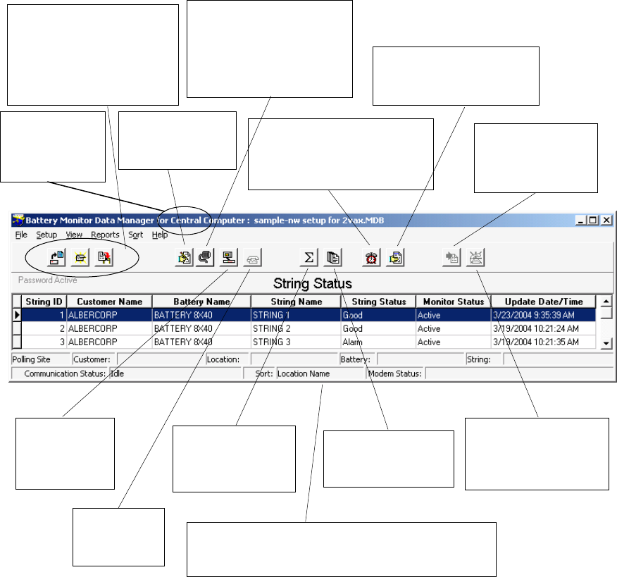
3. String Status Screen Buttons
This page describes buttons on the String Status screen, which appears when the BMDM (Battery
Monitor Data Manager) program starts. Each button name or function is listed in the index for
ready reference.
String Status screen –String Status appears when the BMDM program starts. It lists the strings
in the database and their last known status.
String View screen –String View shows the cells in a string as a bar graph, table or both. It
appears after a string is selected on the String Status screen and computer to monitor
communication is established. You can view a string off-line by selecting View|Offline.
Open / Close /
Back Up Database
(File|selection)
Open or close a file
or back up an Access
database
Set Up System
(Alternate is
Setup|System)
Summary
Displays status
for all strings and
monitors
Connection
Connect to
the selected
string
Set Up Communication
(Setup|Communication)
Define ports, modems,
network timeout. Force
direct connect. Disable
auto polling
Extract All Data
Get data from all
strings in the
system
Historical Events
(View|Historical Events)
List reported events and the
history of one or all strings
Show All Alarm Events
Display the Report Alarm
Event dialog boxes
Summary Report
Create a report for
the entire system
Call All Modem
Strings
Poll all strings
attached via modem
Hang Up
Disconnect
the modem
This portion of the screen displays communication
information, polling status, connection names, and
error status
Indicates
Central, Local
or Service
computer

Program Installation and Options
4-1
4. Program Installation and Options
When installing the BMDM, you will choose Install BMDM Manager. Other screen options
provide you with documentation, connection to the Alber Web site or contact information.
Figure 1. BMDM Opening Screen
4.1. Sample Databases
BMDM sample databases provide strings and data you may use to test button actions, observe
screens, create graphs, and generate reports.
Sample Database for Access - When using Access, at BMDM start-up a message asks, "Do
you want to load a sample database?" Click Yes if you want to explore the BMDM. Clicking
Yes opens the AlberDemo.mdb Access database. If the "load a sample database" message
does not appear, you may enable it on Setup|Preferences. You may also open the sample file
by selecting File|Open|AlberDemo.mdb.
4.2. Installing the BMDM
Before installing the BMDM program, close all other programs. To install the program, insert
the CD into the computer and wait for autorun. If the CD does not run, select Start|Run from
the Windows desktop. At the Run box, type d:\launch (or other drive letter) and follow the
instructions.
4.3. Starting the Program
To start the Battery Monitor Data Manager, double-click the BMDM icon on the desktop.
The first time the program runs, "Do you want to load a sample database?" appears. Click No
if you want to use the Configure Station screens. Refer to Sample Databases and Using
Configure Station.
Program Installation and Options
4-2
4.4. Configuring BMDM to Run as a Windows Service
The BMDM can be run as a service so the application will continue to run in the background
even after the user logs off Windows. The following describes how to configure the BMDM
software as a service.
Note: the BMDM uses the "AlwaysUp" third party application to run the BMDM as a service.
It is automatically installed with the BMDM software package starting with versions 5.86
and SQL 6.33 or later.
To Setup the BMDM as a service using the “AlwaysUp” application, do the following:
1. Check if your operating system is 32 or 64 bit.
2. Click on the appropriate shortcut to install the BMDM Service
a. For 32-bit operating system, click on Start, All Programs, Alber, MPM Manager,
then click on the shortcut Install BMDM Service 32-Bit.
b. For 64-bit operating system, click on Start, All Programs, Alber, MPM Manager,
then click on the shortcut Install BMDM Service 64-Bit.
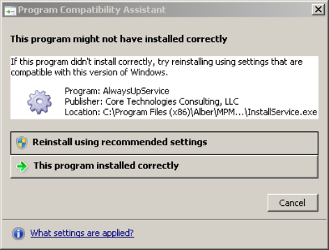
Note: Depending on your operation system, this message may appear. Click on This
program installed correctly to finish the installation.
Figure 2. AlwaysUp Program Compatibility Assistant
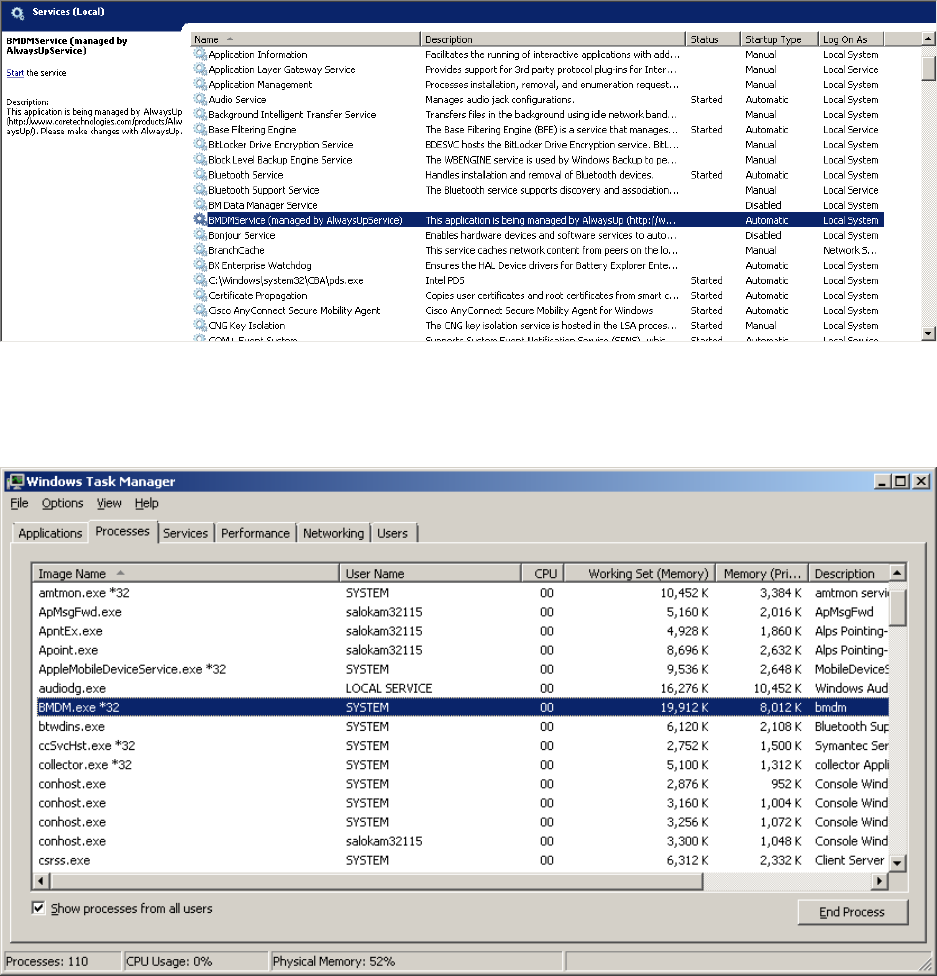
3. Type Windows key + R and enter Services.msc and check for the BMDMService
(managed by AlwaysUpService) entry. Right click the entry and click Start to start
the service.
Program Installation and Options
4-3
Figure 3. BMDM and AlwaysUp Running as a Service
4. Type Ctrl+Shift+Esc to open the task manager. Check for the BMDM.exe *32 under
the Processes tab. This confirms that the BMDM is running as a service.
Figure 4. BMDM is Running as a Service
5. To launch the BMDM user interface, click Start, All Programs, Alber, MPM
Manager, then click on the shortcut Run BMDM Service in Session.
Note: When using the BMDM as a service, use only Run BMDM Service in Session
to launch BMDM. Attempting to run the BMDM using the regular icon shortcut will
cause issues such as having two instances of BMDM.exe running at the same time
or shared violation errors.
Program Installation and Options
4-4
6. It is recommended to replace the regular BMDM shortcut on the desktop with the
Run BMDM Service in Session shortcut to prevent the user from launching the
BMDM incorrectly.
4.5. Database Notes
A BMDM database file contains cell and battery readings and setup data. The BMDM
program stores MPM and BDS data in an Access-based .MDB file.
Access initial database file - During installation, the BMDM places the empty Access
database file mpm-db3.mdb under Program Files\Alber\MPM Manager\Database or in
another folder selected at time of installation. This empty default database opens when you
have not previously opened another database.
Creating a new database - You may create a new Access database using File|New.
Deleting a database - You cannot delete an Access MDB database file from within the
BMDM program. To delete a database, use standard Windows procedures to delete the MDB
file from the folder where it is saved. The file is typically located at Program Files/Alber/
MPM Manager/Database.
Because databases may contain unrecoverable battery data, regularly back up MDB files to
another computer to help prevent data loss. Refer to Automatic and Manual Backup.
4.6. Default Passwords
The BMDM program has one default password, alber, which accesses all areas of the
program and can be changed by the user. It is important to note that different passwords may
be selected for various program areas. New passwords may be alphanumeric and are not case
sensitive.
Additional passwords may be needed when using options. For example, when setting up an
email account for alarm notification, the password is determined externally and is not
changeable using the BMDM. Be certain to record new passwords for reference. If lost, they
cannot be retrieved, and you will have to contact Alber for an unlock code.
System Setup Password - A password for System Setup is stored in the BMDM database
and may be eight characters long. To change it, from the String Status screen, select
Setup|System|Password. Refer to System Setup: Password.
Battery Setup Password - A password for the Battery Setup, Calibration, Diagnostics, and
Check Settings Upload screens is stored in MPM or BDS firmware and must be five
characters. To change it, from String Status, select Setup|Battery|General. Refer to Battery
Setup: General (MPM or BDS).
The Battery Setup password is cleared from the MPM or BDS firmware when the
Alarm Reset switch clears existing names. Refer to the Clear Existing Names (On-site) text in
the Synchronizing Using Check Settings chapter.
Program Installation and Options
4-5
4.7. Computer Types
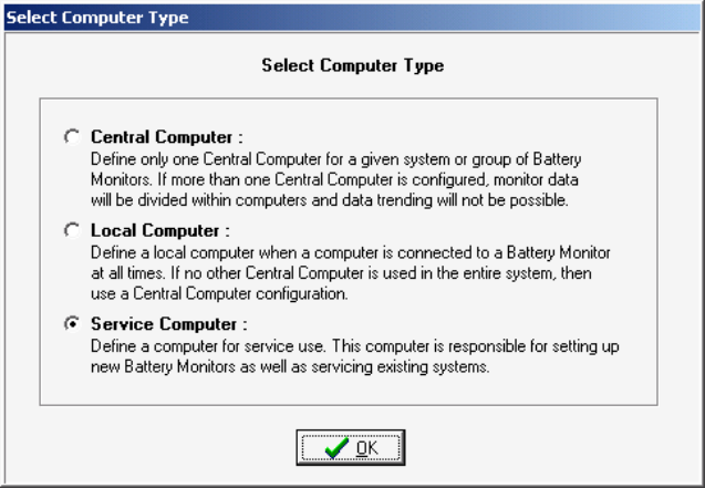
The first time the program runs, a question about computer type appears.
Figure 5. Select Computer Type
You select a computer type only once. Refer to Understanding Computer Types before
answering. The following text is on the Select Computer Type box:
Central Computer - Define only one Central computer for a given system or group of
battery monitors. If more than one Central computer is configured to extract data, the monitor
data could become corrupted.
Local Computer - Define a Local computer when a computer is connected to a battery
monitor at all times. If no other Central computer is used in the entire system, then use a
Central computer configuration.
Service Computer - Define a computer for Service use. This computer is responsible for
setting up new battery monitors as well as servicing existing systems.
On install, the database updates to the latest version. After setup, the String Status screen title
bar indicates the computer type: Central, Local or Service. To change the type, refer to
Changing Computer Type.
Program Installation and Options
4-6
4.8. Changing Computer Type
The Select Computer Type box appears only the first time you install the program. You
cannot change the computer type by re-installing; you must edit a text file. Close all
programs, including the BMDM, and open a text editor, such as Microsoft Notepad or
WordPad under Start|Programs|Accessories.
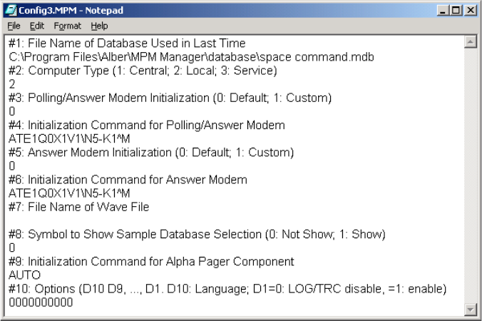
Open the file Config3.MPM under Program Files\Alber\MPM Manager. Using the text
editor, edit the number under the line labeled #2 Computer Type so the digit indicates the
computer type you want. Type 1 for Central, 2 for Local, or 3 for Service. For example, in the
following figure, the 2 under line #2 indicates a Local computer.
Figure 6. Config3.MPM File
Save the text file and close the editor. Run the BMDM program and confirm the title bar
indicates the correct computer type: Central, Local or Service. The Config3.MPM file shown
above is for illustration and not meant to be copied.
Program Installation and Options
4-7
4.9. File Types
The BMDM program uses several file extensions.
MDB ......... An Access database file that stores cell and battery readings and setup data. At
installation, the BMDM creates an empty database file. When the BMDM opens
a backup file, it extracts it from ZIP to MDB.
MPM ......... The configuration file Config3.MPM under Program Files\Alber\MPM Manager
that you may edit to change computer type (Central, Local or Service).
PDF ........... A file format that protects against unintended changes. The Web Report
Generator generates a report as a PDF file every 24 hours.
WAV ......... A sound file used for alarm sounds.
ZIP ............ A compressed file for backup of an MDB database file. Saving the working
database as a backup saves the MDB file as a ZIP.
ZRF ........... A compressed file for reports. The Report Generator displays and prints text and
graphs and saves customized reports in a ZRF format that protects against
changes. You may also view and print ZRF files using the Archive Reader.
4.10. Help Screens
The BMDM has built-in help, which you may activate three ways. Most screens have a
question mark in the upper right corner. Click the question mark, then click the ? cursor over
an item to open a help description. If a screen has no question mark, press the F1 function key
to display help for the entire screen.
Finally, you may click Help on the menu bar to open the text portion of the manual, through
which you may browse using the Table of Contents or Index. The on-screen manual does not
include tables and figures.
Using Configure Station
5-1
5. Using Configure Station
The Configure Station dialog boxes for a Local, Central or Service computer facilitate setting
up communication and alarm reporting. The first time the BMDM runs, at the "Do you want
to load a sample database?" message, select No to display the boxes. You may later open
these boxes by selecting Setup|Configure Station.
String Status > Setup|Configure Station
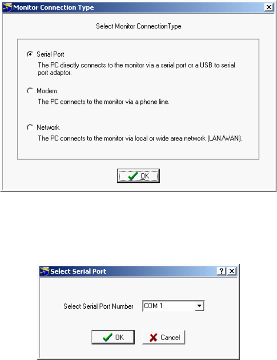
To start Configure Station, select Setup|Configure Station. The Monitor Connection Type
dialog box appears. Because subsequent boxes depend on previous selections, each box is
described without reference to others. For more details on dialog box items, refer to the
sections mentioned.
Figure 7. Configure Station - Monitor Connection Type
Select the method by which the monitor is connected to the computer.
Figure 8. Configure Station - Select Serial Port
If communicating via serial port, select a COM port.
Using Configure Station
5-2
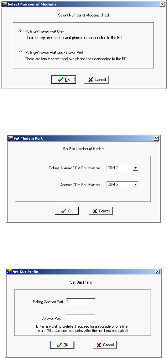
Figure 9. Configure Station - Select Number of Modems
If communicating via modem, select the number of modems in use. For details, refer to
Setting Communications.
Figure 10. Configure Station - Set Modem Port
If communicating via modem, select the modem COM ports. For details, refer to Setting
Communications.
Figure 11. Configure Station - Set Dial Prefix
If communicating via modem, select the dialing prefix. For more details, refer to Setting
Communications.
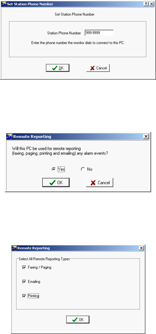
Using Configure Station
5-3
Figure 12. Configure Station - Set Station Phone Number
If communicating via modem, type the telephone number of the computer the MPM or BDS
monitor calls when a system goes into alarm or discharge.
Figure 13. Configure Station - Remote Reporting
To set up parameters for automatic alarm notification using fax, page, email or print,
click Yes.
Figure 14. Configure Station - Remote Reporting Types
Select the methods by which alarms will be reported.
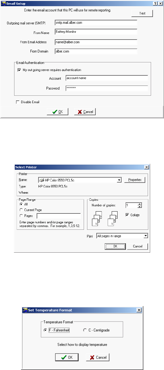
Using Configure Station
5-4
Figure 15. Configure Station - Email Setup
If sending alarms via e-mail, complete this dialog box. Refer to Setting Up an Email Account.
Figure 16. Configure Station - Select Printer
If sending alarms to a printer, this dialog box appears, which is also under File|Printer Setup.
The key item to select is the default printer.
Figure 17. Configure Station - Set Temperature
This box always appears. Select how temperatures will be displayed, either in degrees
Fahrenheit or Centigrade.
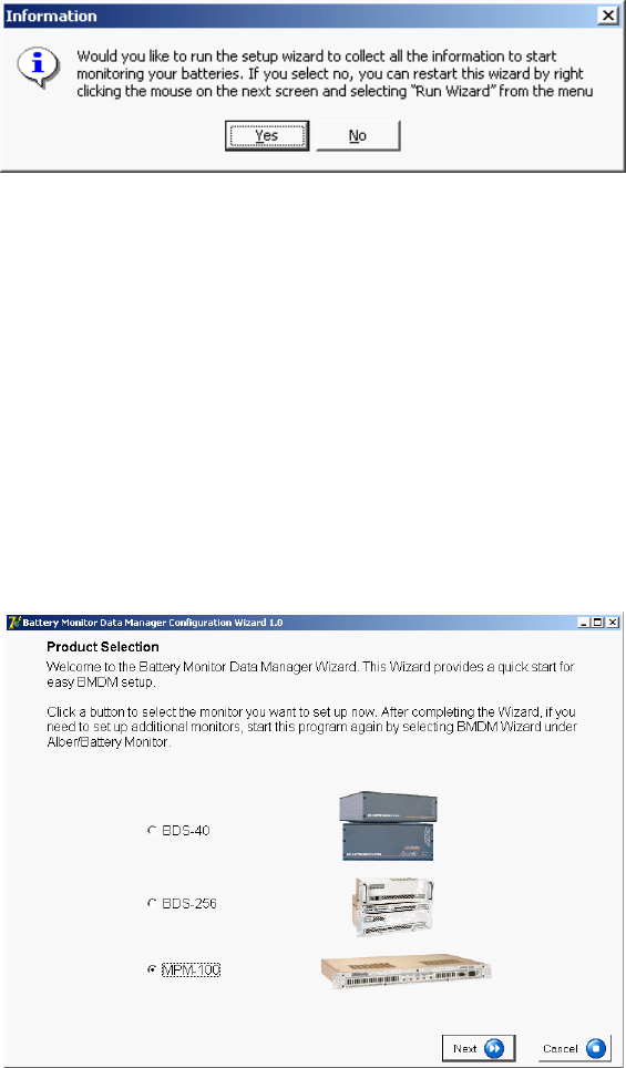
Using Configure Station
5-5
Figure 18. Configure Station - Information
If running the BMDM for the first time with an Access database, this box opens the hardware
setup wizard. You may start this wizard at any time by selecting Setup|Run Wizard.
5.1. BMDM Configuration Wizard
String Status > Setup|Run Wizard or Right-click mouse|Run Wizard
The BMDM Configuration Wizard sets up monitor hardware and battery strings. Using the
Wizard is the recommended method for setup, as it ensures that basic setup requirements are
completed. If you choose not to use the Wizard, you must use the various BMDM setup
dialog boxes.
To start the Wizard, select Setup|Run Wizard or right click on the String Status screen and
select Run Wizard. The self-guided Wizard dialog boxes are not described in this manual.
Figure 19. BMDM Configuration Wizard Opening Screen

Practical Theory: Understanding Computer Types
6-1
Practical Theory
6. Understanding Computer Types
When installing the BMDM program, select one of three computer types: Local, Central or
Service. This section explains the types of computers.
6.1. Central Computer
For managing many sites, use a Central computer. This can be a remote computer with one
modem, or two modems for more than 100 monitors. A computer continuously running the
BMDM can automatically poll the monitoring systems, test for normal status, answer calls
from alarming monitors, receive and store data in a central database, report problems to
personnel, and list conditions on the String Status screen.
If using only one site with a Central computer, you may connect the computer to a monitor
RS-232 rear port for continuous viewing of battery and monitor status. In this configuration,
no other Central computers may exist for the same site.
You may temporarily use a portable computer as the Central computer. To manually extract
data, connect the computer via modem or RS-232 Local port. This type of Central computer
is the least desirable because it cannot automatically poll units for status and automatically
extract data or receive calls from alarming monitors.
Only use one Central computer for all monitors. This is important because only a Central
computer removes data permanently from monitor memory.
Select Central Computer when you want to:
Connect a computer to manage one or more monitors and have the computer manage the
database. Only a Central computer updates the time when passing midnight.
A Central computer can do the following:
Set alarm parameters and test intervals.
Collect data manually or automatically, which permanently removes the data from monitor
memory.
Report string and monitor status automatically.
Upon an alarm occurrence, page personnel, fax or email a report, and sound an alarm.
Control more than 1000 monitors from a remote location (not on-site).
Assign location, battery, and string names when setting up a new system.
Calibrate a monitor when the Central computer is on-site.
Note: You may set up an on-site, remote (off-site) or notebook computer as Central, but there
must be only one Central computer polling a monitor. A serial multiplexer is required when
using more than one monitor with an on-site computer.
Practical Theory: Understanding Computer Types
6-2
6.2. Local Computer
For continuous, on-site display of battery information, use a Local computer. You can use a
Local computer with a Central computer. A Local computer performs most Central computer
functions, except that only a Central computer can permanently remove data from monitor
memory.
MPM CAUTION: The MPM front panel Local Port switch enables the front RS-232 port or
optional rear RS-232 port, fiber optic port or LAN port. The front port is for servicing only.
When the switch is lit, the front port is selected. Use the rear port for connecting to a
permanent Local computer, Service computer or on-site Central computer. Use the front port
for using a computer for servicing. For example, if the MPM is not near the Local computer,
you may need an on-site connection for calibration or troubleshooting.
BDS CAUTION: A BDS front panel switch can disable the rear RS-232 Local port or the
fiber optic port. Select the Local position to use the front Local port. When the switch is lit,
the front Local port is selected. Be sure to select the rear Local port after use to re-establish
connection to the Local computer.
The BMDM program on a Local and Central computer is the same, except it is set for Local
rather than Central to implement special data handling when connected to a monitor.
Select Local Computer when you want to:
Connect a computer to a monitor to continuously view monitor and battery status on-site.
A Local computer can do the following:
Set alarm parameters and test intervals.
Calibrate a monitor.
Collect data manually and automatically without permanently removing the data from
monitor memory.
Report string and monitor status automatically.
Upon an alarm occurrence, page personnel, fax or email a report, and sound an alarm.
Note: When no network is available, a serial multiplexer is required when using more than
one monitor.
Practical Theory: Understanding Computer Types
6-3
6.3. Service Computer
The Service computer can be a desktop or notebook computer temporarily connected to a
monitor on-site to view battery information. The BMDM software on the Service computer is
the same as that on a Central or Local computer, except it is set for Service during setup. A
Service computer lets personnel call a site from a remote location and observe a situation
without removing any data the Central computer might be waiting to extract.
Select Service Computer when you want to:
Connect a computer on-site or from a remote location to view battery data real time or when
you want to set up new monitors.
A Service computer can do the following:
Set up a new monitor, including alarm parameters and test intervals.
Calibrate a monitor.
Collect data manually without permanently removing the data from memory.
6.4. Facility Monitor
You can connect the monitor to a facility monitor or any device that communicates using
MODBUS ASCII protocol. Third-party vendors can view all information available to the
Data Manager. Albér can supply the register map and application notes for this
implementation. A facility monitor can connect to a BDS or MPM system via RS-232 or
network. Dry closure contacts are available for monitoring alarm status. Refer to MPM
MODBUS Application Notes at www.alber.com for more details.

Practical Theory: Understanding Polling, Extraction and Backup
7-1
Practical Theory
7. Understanding Polling, Extraction and Backup
This chapter explains how polling, extraction, and backup are implemented in Central, Local,
and Service computers running Access. A table summarizes the functions. The terms status
and data are used in this chapter as follows:
Status defined - A report of the normal and error conditions and alarm events for the strings
being monitored.
Data defined - Data (or string data, battery data) are the voltage float values, resistance
values, and discharge values acquired through testing.
The Extract function never deletes status from the monitor. Depending on computer type,
Extract may delete data from the monitor.
7.1. Types of Polling
Polling can be automatic or manual for computers using an Access database.
Polling defined - The process of having the BMDM program connect to the BDS or MPM
monitor and request present battery and monitor status. Polling may be done automatically.
Auto Polling via RS-232 or LAN (Continuous Polling) - The computer automatically
connects to one or more monitors and then continually polls each string in the database
sequentially. This continuous autopolling is done via network or RS-232 direct connection,
not via modem. The polling interval is adjustable.
Auto Polling via Modem - Autopolling via modem occurs one time per day. Each string is
polled, then autopolling ceases until the next day. This prevents having the telephone line
continuously in use.
Disable Auto Polling / Auto Answering - To allow auto polling or auto answering, do not
select this box on Communication Setup.
7.2. Extraction of Data
Extraction can be automatic or manual for computers using an Access database. Status is
never deleted using Extract.
Extraction defined - Extraction is the process of having the BMDM program connect to a
BDS or MPM monitor and transferring float, resistance, discharge, and alarm data from
monitor memory to the BMDM database. Depending on computer type, extraction may copy
or copy then remove the data from the monitor. Refer to the table in this chapter.
Manual Extraction - After BMDM to MPM or BDS connection, you may initiate manual
extraction by clicking of any of these buttons: View Resistance, View Intercell, View Current
Historical Alarms, View Discharge, Extract All, and History. You may also start manual
extraction by clicking the Extract All Data button or the Extract Data pop-up menu item
when enabled.
Auto Extraction - Enabled by checking the Auto Extract Data box on Communication Setup.
With auto extraction, data transfers from the monitor to the BMDM database one time a day,
at 10PM for a Local computer or at 12 midnight for a Central computer.

Practical Theory: Understanding Polling, Extraction and Backup
7-2
7.3. Polling and Extraction Notes
Auto Polling via Modem with a Central Computer - Central computer autopolling via modem
is available once a day at midnight. Select Modem on Setup|System|Link, set Polling to
Enable on Setup|System|Link, and do not check the Disable Auto Polling / Auto Answering
box on Setup|Communication. Modem connection does not permit continuous autopolling.
Continuous Auto Polling - A Central, Local or Service computer connected to the monitor via
RS-232 or network can perform continuous autopolling. Set Polling to Enable on
Setup|System|Link, and do not check the Disable Auto Polling / Auto Answering box on
Setup|Communication. Using a Service computer for continuous polling is not recommended.
Pause Auto Polling - On String Status, you may select Setup|Pause Auto Polling to
temporarily suspend continuous polling. This is convenient if you are selecting other strings
in the list. Selecting Pause Auto Polling does not change settings on the Communication
Setup or Link dialog boxes.
Extracting Data via Modem with a Central Computer - A Central computer connected via
modem can extract data. Select Auto Extract Data on Setup|Communication. The Central
computer polls monitor status at midnight, copies monitor data to the Central computer
database, and deletes the data from the monitor.
Extracting Data with a Central or Local Computer via RS-232 or Network - A Central or
Local computer connected via RS-232 or network can extract data. A Service computer
cannot extract data. Select Auto Extract Data on Setup|Communication. During autopoll at
10PM, a Local computer copies monitor data to the Local computer database, but does not
delete the data from the monitor. At midnight, the Central computer autopolls monitor status,
copies the monitor data to the Central computer database, and deletes the data from the
monitor.
7.4. Automatic and Manual Backup
Within this section, a backup is defined as a file that is generated by the BMDM program
automatically or upon user request.
The BMDM program stores data from the MPM or BDS in a Microsoft Access compatible
file. As defined in File Types, an MDB file is a database file that stores cell and battery
readings and setup data. A WinZip ZIP file is a compressed file for backup of an MDB
database file.
The working database is automatically saved as a ZIP file at midnight. The number 1 is
appended to the file name and the extension becomes ZIP. Backups are made for three days,
appended with 1, 2 or 3. On the fourth day, the oldest backup is overwritten. On the first of
the month, another backup is created, with the month and year appended to the file name. On
subsequent first days of each month, another file is created, again with the month and year
appended.
At any time, to save a database as an MDB database file, select File|Save As. To save the
MDB file as a ZIP backup file, select File|Backup Database. To open a backup file, select
File|Open Backup. When the BMDM opens a backup file, it converts it from a ZIP to an
MDB database file.

Practical Theory: Understanding Polling, Extraction and Backup
7-3
The following table summarizes polling, extraction and backup for Central, Local, and
Service computer types.
Computer
Type1 and
Database
Connected
Via
Backup
Auto Polling
Auto Extraction2
Central
Access
Modem
Midnight
(12:00AM)
Midnight
(12:00AM)
Copies the status; copies then deletes data.
Concurrent with autopoll.
Central
Access
RS-232
Midnight
(12:00AM)
Continuous
Copies the status; copies then deletes data.
Concurrent with first autopoll after 12AM.
Central
Access
LAN
Midnight
(12:00AM)
Continuous
Copies the status; copies then deletes data.
Concurrent with first autopoll after 12AM.
Local
Access
Modem
Midnight
(12:00AM)
10:00PM
Copies the status; copies data. Concurrent
with autopoll.
Local
Access
RS-232
Midnight
(12:00AM)
Continuous
Copies the status; copies data. Concurrent
with first autopoll after 10PM.
Local
Access
LAN
Midnight
(12:00AM)
Continuous
Copies the status; copies data. Concurrent
with first autopoll after 10PM.
Service
Access
(See Note 1)
Modem
Midnight
(12:00AM)
Autopolling
not available
(Manual only)
Auto extraction not available.
(Manual only)
Service
Access
(See Note 1)
RS-232
Midnight
(12:00AM)
Continuous
Auto extraction not available.
(Manual only)
Service
Access
(See Note 1)
LAN
Midnight
(12:00AM)
Continuous
Auto extraction not available.
(Manual only)
Note 1: End-user use of a computer set as Service type is not recommended.
Note 2: Status and data copy and delete functions are the same for manual extraction.
Figure 20. Computer Types: Backup, Polling and Extraction Table

Practical Theory: Understanding System Installation
8-1
Practical Theory
8. Understanding System Installation
This section describes how to set up the BMDM program and put the MPM or BDS monitor into
operation. To install the MPM or BDS, refer to the Installation Instructions manual, then read this
section before placing the system into service.
You should initially configure monitor settings on-site through the front or rear panel RS-232
Local port during installation. You may change programmable settings later.
New monitors have location, battery, and string names blank and auto call-out and alarms
disabled. This prevents nuisance alarms and unintentional communication during setup. The
location, battery, and string names must be unique for each system, known to the user, and
correspond between the monitor and calling computer for a connection to occur.
The MPM monitor loses communication with a locally-connected computer during modem
handshaking when a monitor calls out. After connection, normal operation resumes.
8.1. Connecting Using a Local Computer
The following describes how to set up an MPM or BDS monitor for use with a Local
computer when a Central computer is being used off-site.
To set up the system . . .
If you need more help, refer to
1. Install the Data Manager as a Local computer. Installing the Data Manager (BMDM) Software.
2. Set communication parameters for a direct connect.
Communication Port Settings.
3. Set up for a new system.
Setting Up a New MPM or BDS System.
4. Direct connect the monitor to the computer.
Local Port Connection for MPM or BDS.
5. Establish communication between the monitor and
the computer.
Connecting via the RS-232 Local Port.
6. Perform battery setup and set alarm thresholds, test
intervals, and options.
Programming Battery Setup for the MPM or BDS.
7. Synchronize the monitor to the Central computer.
Synchronizing Using the Check Settings.
The Local computer and monitor are now ready to operate.

Practical Theory: Understanding System Installation
8-2
8.2. Connecting Using a Central Computer
The following describes how to set up an MPM or BDS for use with a Central computer. You
may set up an on-site or notebook computer as a Central computer, but there must be only
one Central computer polling a monitor.
• If the Central computer is an on-site computer:
To set up the system . . .
If you need more help, refer to
1. Install the Data Manager as a Central computer.
Installing the Data Manager (BMDM) Software.
2. Set communication parameters.
Communication Port Settings.
3. Set up for a new system.
Setting Up a New MPM or BDS System.
4. Direct connect the monitor to the computer.
Local Port Connection for MPM or BDS.
5. Establish communication between the monitor and
the computer.
Connecting via the RS-232 Local Port.
6. Synchronize the monitor to the computer. (MPM
only)
Synchronizing Using the Check Settings.
7. Perform battery setup, and set alarm thresholds, test
intervals, and options. Programming Battery Setup for the MPM or BDS.
8. Synchronize the monitor to the computer. (BDS only)
Synchronizing Using the Check Settings.
The Central computer and monitor are now ready to operate.
• If the Central computer is a remote (off-site) computer:
To set up the system . . .
If you need more help, refer to
1. Set up the monitor.
Service Computer or Local Computer.
2. Install the Data Manager as a Central computer.
Installing the Data Manager (BMDM) Software.
3. Set communication parameters.
Communication Port Settings.
4. Connect the computer modem to the telephone line.
5. Set up for a new system.
Setting Up a New MPM or BDS System.
6. Establish communication between the monitor and
computer.
Connecting via a Modem.
7. Synchronize the monitor to the computer.
Synchronizing Using the Check Settings.
The Central computer and monitor are now ready to operate.

Practical Theory: Understanding System Installation
8-3
8.3. Connecting Using a Service Computer
The following describes how to set up a computer as a Service computer.
• If the Service computer is a direct connection (on-site) computer for setting up a new
MPM or BDS monitor:
(Use this option only if a Local computer is not available.)
To set up the system . . .
If you need more help, refer to
1. Install the Data Manager as a Service computer on a
notebook (portable) computer.
Installing the Data Manager (BMDM) Software.
2. Set communication parameters.
Communication Port Settings.
3. Set up for a new system.
Setting Up a New MPM or BDS System.
4. Direct connect the monitor to the computer.
Local Port Connection for MPM or BDS.
5. Establish communication between the monitor and
computer.
Connecting via the RS-232 Local Port.
6. Perform battery setup, and set alarm thresholds, test
intervals, and options.
Programming Battery Setup for the MPM or BDS.
7. Synchronize the monitor to the computer.
Synchronizing Using the Check Settings.
The Service computer and monitor are now ready to operate.
• If the Service computer is a direct connection (on-site) computer for viewing battery data,
and a copy of the Central computer database is available:
To set up the system . . .
If you need more help, refer to
1. Install the Data Manager as a Service computer on a
notebook (portable) computer.
Installing the Data Manager (BMDM) Software.
2. Copy the database from the Central computer to the
Service computer.
Data Manager Database for file names.
3. Set communication parameters. Communication Port Settings.
4. Direct connect the monitor to the computer. Local Port Connection for MPM or BDS.
5. Establish communication via the site selected from
the String Status. Connecting via the RS-232 Local Port.
To view battery data, refer to Viewing Battery and Monitor Status.

Practical Theory: Understanding System Installation
8-4
• If the Service computer is a remote connection (off-site) computer for viewing battery
data via telephone line, and a copy of the Central computer database is available:
To set up the system . . .
If you need more help, refer to
1. Install the Data Manager as a Service computer.
Installing the Data Manager (BMDM) Software.
2. Copy the database from the Central computer to the
Service computer.
Data Manager Database for file names.
3. Set communication parameters. Communication Port Settings.
4. Connect the computer modem to the telephone line.
5. Establish communication via the site selected from
the String Status. Connecting via a Modem.
To view battery data, refer to Viewing Battery and Monitor Status.
• If the Service computer is a remote connection (off-site) computer for viewing battery
data via telephone line, and a copy of the central database is not available:
To set up the system . . .
If you need more help, refer to
1. Install the Data Manager as a Service computer. Installing the Data Manager (BMDM) Software.
3. Set communication parameters. Communication Port Settings.
2. Connect the computer modem to the telephone line.
4. Set the telephone number and the MUX ID number if
required. (MPM only) Setting Up a New MPM or BDS System.
5. Set the telephone number, the MUX ID number if
required, the string number and the configuration to
the BDS. (BDS only)
Setting Up a New MPM or BDS System.
6. Establish communication via the Service location.
Connecting via a Modem
7. Synchronize the monitor to the computer.
Synchronizing Using the Check Settings
To view battery data, refer to Viewing Battery and Monitor Status.

Practical Theory: Understanding How Data is Stored
9-1
Practical Theory
9. Understanding How Data is Stored
This section describes how the BMDM processes data and how the MPM or BDS stores the data.
For details about how the BMDM creates and backs up database files, refer to Understanding
Polling, Extraction and Backup.
9.1. Data Storage in the MPM
Data in the MPM is stored in nonvolatile E2 memory, which retains about a year's worth of
typical data. Collected data is stored until transferred to the Central or Local computer. This
same memory stores setup and calibration data, which is backed up to the Central or Local
computer during initial setup; this process is called synchronizing. Flash nonvolatile memory
stores uploads of new MPM firmware. You can upgrade the firmware on-site or remotely.
The MPM stores these kinds of data:
Alarms - 100 records that show when a parameter went into alarm and left alarm, and
maximum alarm level. Older records in memory are overwritten with more recent events.
(Older records uploaded to a computer are not overwritten.)
Discharge - 20.5kb of nonvolatile memory are allocated for discharge data. Memory size and
the number of cells monitored limit the data stored: many short or a few full discharges.
Each data point requires ten bytes of memory. If the discharge storage threshold is 10mv, and
a typical discharge for 24 cells was to discharge 1.875 volts per cell, and the cell voltage was
to drop to 1.96 volts with load applied, you would calculate the memory required as:
20,500 bytes / ( ( ( (1.96-1.875) / 0.010 volts) x 10 bytes) x 24 cells) = 10 discharges
This worst case assumes all cells discharge to 1.875 volts. Increasing the discharge storage
threshold can raise the number of discharges the monitor can store. Time stamped data allow
a full analysis of battery performance during the event.
Resistance - 1.6kb of nonvolatile memory are allocated for resistance data. Memory limits
the number of resistance tests stored. To calculate the number of resistance records available,
use the formula:
1600 bytes / ( (Number of cells x 2) + 10)
For a string of 24 cells, there is enough memory for 27 records.
Historical Data - With 1.65kb of nonvolatile memory available, historical readings of cell
voltage, temperature, overall voltage, and current are taken at intervals set under Battery
Setup. To calculate the number of historical records available, use the formula:
1650 bytes / ( (Number of cells x 2) + 18)
For a string of 24 cells, there is enough memory for 25 records.
Practical Theory: Understanding How Data is Stored
9-2
9.2. Data Storage in the BDS
Data in the BDS is stored in nonvolatile SRAM memory, which retains about nine month's
worth of typical data. Collected data is stored until transferred to the Central or Local
computer. This same memory stores setup and calibration data, which is backed up to the
Central or Local computer during initial setup; this process is called synchronizing. Flash
nonvolatile memory stores uploads of new BDS firmware. You can upgrade the firmware
on-site or remotely.
The BDS stores these kinds of data:
Alarms - 100 records that show when a parameter went into alarm and left alarm, and
maximum alarm level. Older records in memory are overwritten with more recent events.
(Older records uploaded to a computer are not overwritten.)
Discharge - 160kb of nonvolatile memory are allocated for discharge data. Memory size and
the number of cells monitored limit the data stored: many short or a few full discharges.
Each data point requires ten bytes of memory. The discharge storage threshold is 10mv. If a
typical discharge for 192 cells was to discharge 1.65 volts per cell, and the cell voltage was to
drop to 1.96 volts when load was applied, you would calculate the memory required as:
160,000 bytes / ( ( ( (1.96-1.65) / 0.010 volts) x 10 bytes) x 192 cells) = 2.7 discharges
This worst case assumes all cells reach end voltage. Time stamped data allow a full analysis
of battery performance during the event.
Resistance - 10.6kb of nonvolatile memory are allocated for resistance data. Memory limits
the number of resistance tests stored. To calculate the number of resistance records available,
use the formula:
10,600 bytes / ( (Number of cells x 4) + 30)
For a string of 192 cells, there is enough memory for 12 records.
Historical Data - With 32kb of nonvolatile memory available, historical readings of cell
voltage, temperature, overall voltage, and current are taken at intervals set under Battery
Setup. To calculate the number of historical records available, use the formula:
32,000 bytes / ( (Number of cells x 2) + 38)
For a string of 192 cells, there is enough memory for 75 records.

Practical Theory: Understanding the Time to Go Algorithm
10-1
Practical Theory
10. Understanding the Time to Go Algorithm
The battery Amp-hour (Ah) rating indicates the current (Amps) the battery can deliver over time
(hours). For example, if a battery can deliver 5 Amps for 20 hours, it has a 100Ah rating.
However, because discharge rate, temperature, and age affect battery capacity, Amp-hour rating
can vary. A 100Ah battery that discharges over two hours might deliver only 56Ah. To
compensate for this nonlinearity, you can use Peukert's Equation to estimate the Amp-hours
remaining (or time to go) in a lead-acid battery based on discharge rate. If capacity testing is not
an option, you can get the numbers for the equation from the discharge curves on manufacturers'
data sheets, but the result will be less accurate than that obtained by using values gotten from
actual capacity testing.
Peukert's Equation demonstrates how the Amp-hour capacity of a lead-acid battery varies
according to rate of discharge. Rather than Ah = I x T, the Peukert Equation reads:
C = Int
where constant C = the theoretical capacity of the battery, I = the discharge current in Amps,
t = the time of discharge, and the exponent n = the Peukert number, a constant for the given
battery. The exponent value can vary from greater than 1 to about 2. Values closer to 1 indicate a
well performing battery; higher numbers indicate more capacity diminishes when the battery is
discharged at higher rates.
Calculate the Peukert number by determining the capacity obtained at any two discharge rates:
(log t2 – log t1)
(log I1 – logI2)
where t1 is the hours of discharge at current I1 and t2 is the hours of discharge at current I2.
To determine the Peukert number, discharge the same, fully charged battery twice at convenient
discharge rates.
First, discharge the battery below the normal discharge rate. When the battery reaches discharge
level, as determined from manufacturers' spec sheets, note the Ah consumed and the time the
discharge took. Calculate the average Amps by dividing the Ah consumed by the length of time.
For example, if the Ah consumed was 300 and the discharge took 50 hours, the average Amps
equals 6. Use this value for I1 in the above formula and use the time the discharge took for T1.
Charge the battery and repeat the process for a discharge rate higher than normal. Use the
resulting values for I2 and T2 in the formula. Calculate the value for n to obtain an exponent
accurate for your normal rate. Use this exponent n in the Peukert Equation to estimate time
remaining during a normal discharge.
Performing two capacity tests to obtain the variables for Peukert's Formula can yield accuracy as
good as 0.5% to 1%.
n =
Practical Theory: Understanding the Time to Go Algorithm
10-2
Although the Time to Go calculation may offer a close estimate, many other battery parameters
affect run time as a battery ages. These aging phenomena show up as different failure modes and
influence the accuracy of the Time to Go calculation. Albér recommends that you not rely solely
on the Time to Go data for battery run time and that you only consider the Time to Go as an
estimate.
To activate the Peukert's Equation algorithm in the BMDM program, open the
Setup|Battery|Discharge dialog box and assign values in the Time to Go area.
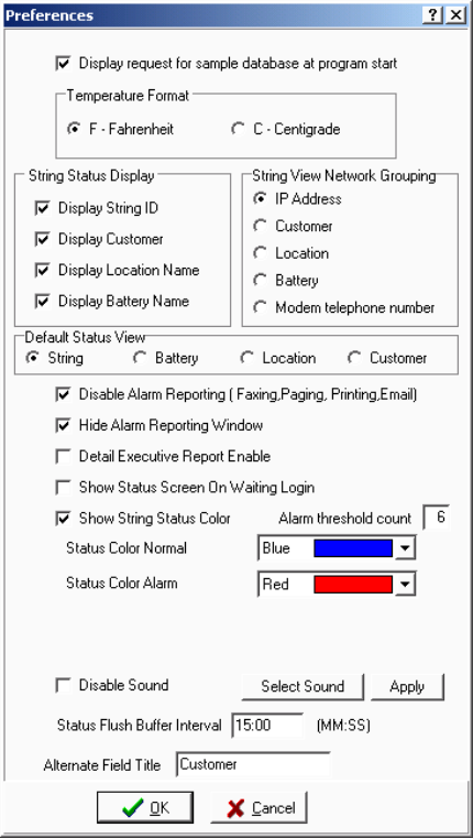
Selecting Preferences
11-1
11. Selecting Preferences
String Status > Setup|Preferences
At any time, you may open the Preferences dialog box to change program appearance or activate
options.
Figure 21. Preferences
Display Sample Database - To display the message, "Do you want to load a sample database?"
at BMDM program start, select this box.
Temperature Format - Select a temperature format. Do not change format after setting up the
system. Stored temperatures will not convert between F (Fahrenheit) and C (Centigrade or
Celsius).
String Status Display area - Selecting Display String ID, Display Customer, Display Location
Name or Display Battery Name displays these columns on the String Status screen.
Selecting Preferences
11-2
String View Network Grouping area - When connected to a string, a drop-down list at the top of
the screen shows the name of the string being displayed. On Preferences, clicking IP Address,
Customer, Location, Battery or Modem telephone number filters the list by these parameters.
The default filter is IP Address. These filters are active for network connection only.
Default Status View area - Select an option button to have the default String Status screen
display Battery Status, Location Status or Customer Status at program start.
Disable Alarm Reporting - Select to globally disable all alarm report functions. This selection
overrides alarm settings on Setup|System|Reporting, which apply to specific strings.
Hide Alarm Reporting Window - Select to stop the report alarm box from popping up.
Detail Executive Report Enable - Only appears on a Central computer. Select to automatically
generate daily executive reports, which are saved in PDF format at Program Files\Alber\
MPM Manager\Web \String Summary or System Summary. These reports are viewed when
connecting via the Web interface.
Show Status Screen on Waiting Login - Check to keep the String Status screen displaying when
no user is logged in.
Show String Status Color - To have color indicate status on the String Status screen, select this
box, an alarm threshold count, and a color.
Alarm Threshold Count - This is the number of alarms required on a string to make the Normal
color change to the Alarm color.
Status Color Normal - A good status, with no alarms, displays in the color selected from
this Status Color Normal drop-down box.
Status Color Alarm - A string in alarm with the number of alarms selected in the Alarm
Threshold Count box displays in the color selected in this Status Color Alarm drop-down box.
Disable Sound - Select to globally disable alarm sounds. Not selecting enables a sound upon an
alarm. You must also check Sound Alarm on Setup|System|Reporting, which applies to specific
strings. Refer to Setting Up a New MPM or BDS System. To select an alarm sound,
click Select Sound on Preferences and choose a sound. Click Open then Apply to hear the sound.
Note: When in Battery setup and remote reporting is disabled, the alarm threshold must be set to
one. The string status is set to have an alarm and the string status color is automatically applied.
Status Flush Buffer Interval - Select an interval in minutes and seconds to have the polling
status saved to the database. The default interval is 15 minutes.
Alternate Field Title - Type a name in this field to assign the Customer field title another name,
such as Region or Subdivision. The new name will appear in various program areas where the
word Customer appeared.
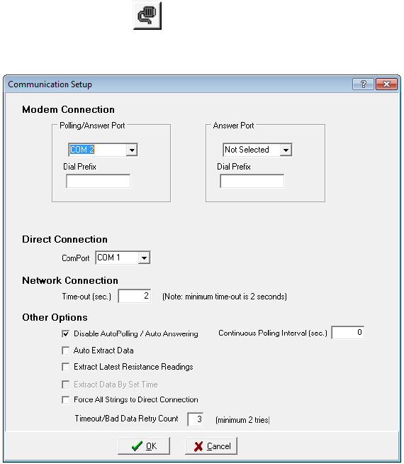
Setting Communications
12-1
12. Setting Communications
String Status > Setup communication or Setup|Communication
Select this dialog box to define communication settings.
Figure 22. Communication Setup
Polling/Answer Port and Answer Port - Using the drop-down lists, define one or two modem
COM ports for monitor communication. If you define two COM ports, one port calls and polls the
monitors, and the other answers calls from the monitors. If you define only one port, it both polls
and answers. Define one port from the Polling/Answer Port list and choose Not Selected under
Answer Port. For larger systems, use two modems to allow simultaneous polling and remote
reporting.
Dial Prefix - This is the number, usually a 9, that accesses an outside phone line. Type at least
two commas after the number for a time delay. Leave this box blank if the computer directly
connects to an outside line.
Direct Connection - Com Port - If you selected the Direct button on System Setup|Link, select a
COM port. If any strings are configured as Direct Connect, then select the Com Port number.
Network Connection - Time Out - This sets the time allowed for connecting to the network,
typically 2 seconds.
Setting Communications
12-2
Disable Auto Polling / Auto Answering - For computer–monitor connection via RS-232 or
network, not selecting this box enables continuous polling. With continuous polling, the BMDM
polls monitor string status at the time interval set in the Continuous Polling Interval box. Refer to
Understanding Polling, Extraction and Backup for definitions of status and data.
Extract Latest Resistance Readings – enabling this option, allows you to view the latest
resistance readings when resistance history has previously been extracted by a central computer.
This allows you to view the latest resistance readings without the central computer database.
Continuous Polling Interval (seconds) - If Disable Auto Polling / Auto Answering is not
selected, set the time interval that polling occurs. The BMDM continually polls monitor string
status at this interval, typically 15 seconds.
Auto Extract Data - Automatic data extraction removes (Central computer) or copies (Local
computer) data from monitor memory when polling each monitor. Normally, select Auto Extract
Data for a Central computer; otherwise, you will have to manually call each site and extract data.
Refer to Understanding Polling, Extraction and Backup for polling details.
Extract Data by Set Time - To extract data at a time other than midnight, select Auto Extract
Data, then select this box and type a time in the Extract Time field on System Setup Link for each
string.
Force All Strings to Direct Connection - Use with a Local or Service computer using a database
that has modem or network connections. Select this box to connect to an MPM or BDS using the
USB or RS-232 port. This feature saves having to modify the database Link connections and is
useful when temporarily using a Local or Service computer.
Timeout / Bad Data Retry Count - This is the number of times the program attempts to poll
data from a monitor if previously unsuccessful.
12.1. Determining the USB COM Port
If your MPM or BDS system has USB capability, you must determine which COM port the
computer selects for the USB driver and then set the COM port in the BMDM program.
Note: Items on your version of Microsoft Windows may have different names from those
described in the following text.
First, connect the MPM or BDS system to the USB port on the computer and power up the
computer and the system.
From the Windows desktop, click Start|Settings|Control Panel|System. On the System dialog
box, click the Hardware tab, then click the Device Manager button.
Expand the Ports folder, then find the listing for the USB. A typical listing might read: USB
Serial Port (COM 4). Write down the COM port number for later use, then close the Device
Manager dialog box and exit back to the Windows desktop.
On the Communication Setup dialog box in the BMDM program, select the previously noted
COM port on the Direct Connection drop-down list. Click OK.
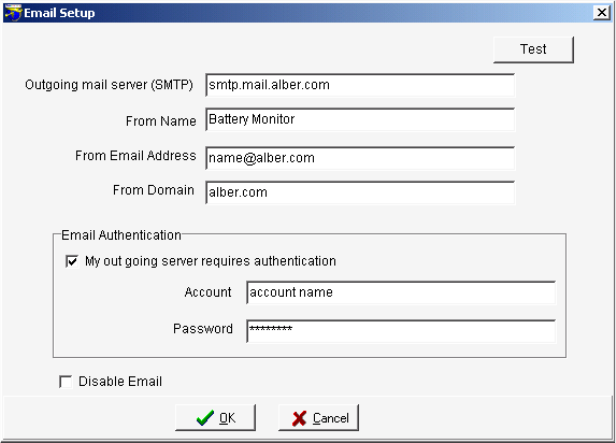
Setting Up an Email Account
13-1
13. Setting Up an Email Account
String Status > Setup|Email Setup
Use Email Setup to set up the account under which the BMDM sends emails. This dialog box
contains the global Email Disable selection.
Figure 23. Email Setup
Outgoing Mail Server (SMTP) - Specify the mail server for outgoing messages. Obtain this
from your Internet service provider or network administrator.
From Name - Type the name that will appear in the recipient's email From field.
From Email Address - Type the email address the BMDM will use as a sender.
From Domain - Type the mail server domain name of the outgoing mail server.
My outgoing server requires authentication - Select this box if your email requires ESMTP.
This specifies that you must log on to your outgoing mail server.
Account - Type the mail server account user name or number.
Password - Type the password for the account.
Disable Email - This selection globally disables all BMDM email settings. To not send any alarm
or other BMDM emails, check this box.
Test - To send an email to test the setup, click the Test button. The Test Email dialog box
appears.
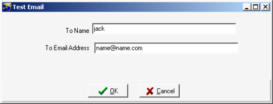
Setting Up an Email Account
13-2
13.1. Testing Email
String Status > Setup|Email Setup|Test
The Test Email box tests the settings on the Email Setup dialog box.
Figure 24. Test Email
At To Name and To Email Address, type the recipient's name and email address. Click OK
to send the email and close the box. Confirm the email is received at the location to which it
was sent.

Setting Up a New MPM or BDS System
14-1
14. Setting Up a New MPM or BDS System
String Status > Setup system or Setup|System
BMDM setup involves defining what systems exist. Each system setup must identify customer,
location, contacts, battery and string information, and other data. All System Setup dialog boxes
except String are identical for both the MPM and BDS.
14.1. System Setup: General Notes
System Setup is password protected. After selecting Setup|System, type the password and
click OK. The password times out after five minutes or you may click the top left Password
Active to disable it. If the password is incorrect, the System Setup boxes appear, but New,
Save and Delete are inactive. You can have different Battery Setup and System Setup
passwords. Refer to Default Passwords.
The first time the String Status screen appears, no status information exists. As you add new
systems, they are listed with Unknown status. To set up a new system, select Setup|System,
click New on the Customer dialog box, and complete the System Setup boxes. Systems
previously set up are listed on String Status. When you click Setup|System, the name
highlighted in the list appears in the Customer dialog box. Click New to add a new system
(new customer).
CAUTION: If you fail to click the New button, you will overwrite the previously saved
customer information.
The New button on the Location, Battery, and String boxes adds a new location under an
existing customer, a new battery under an existing location, or a new string under an existing
battery.
To change names or information for an existing system, use the Setup|System dialog boxes. If
BMDM and monitor location, battery or string names do not match, connection fails and an
error message appears. Blank spaces or hyphens can affect a name.
During system setup, if you close before completing and saving the Customer, Location,
Battery and String details, the names will not appear on String Status. To resume editing,
click Setup|System, select the Customer, Location, Battery or String box, and choose the
name from the Name drop-down list.
To display the String ID, Customer Name, Location Name and Battery Name columns on the
String Status screen, select the boxes on Setup|Preferences.
Depending on which System Setup box is displayed, clicking Delete removes all information
for the displayed customer, location, battery or string. All associated set up data will be
permanently lost.
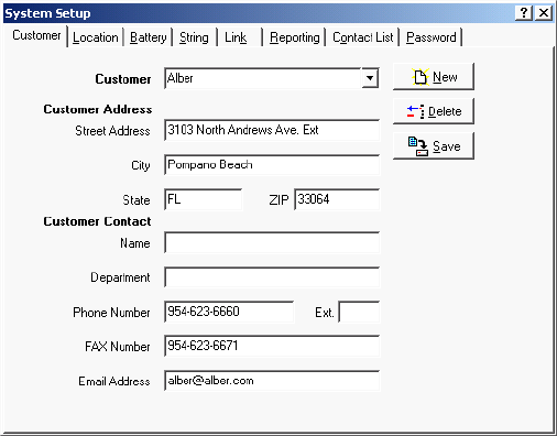
Setting Up a New MPM or BDS System
14-2
14.2. System Setup: Customer
String Status > Setup|System|Customer
Use the Customer dialog box to add new customer details.
The Customer tab and Customer field names may be changed to another name, such as
Region, by selecting Setup|Preferences, then typing a new name at Alternate Field Title.
Figure 25. System Setup - Customer
CAUTION: Clicking the Delete button deletes all information for the displayed customer. All
locations, batteries, and strings set up for the customer will be lost.
Customer Name (required) - To add new customer details, click New and type the customer
name. If monitoring only one customer, you may identify a region, division, etc. Complete
the Customer Address details.
Note: You cannot have two identical customer names. Selecting different customers changes
the available locations on the Location dialog box.
Customer Contact - Type the name and contact information of the person at the customer
location responsible for the battery system. This name may be used for reports faxed using
Setup|System|Reporting.
When finished, click Save to save to the database or click the Location tab to continue setup.
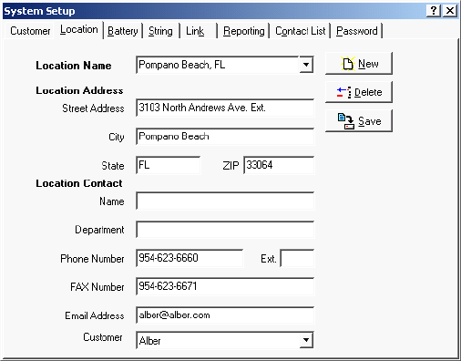
Setting Up a New MPM or BDS System
14-3
14.3. System Setup: Location
String Status > Setup|System|Location
Before completing the Location dialog box, confirm the correct customer is selected on the
Customer box.
Figure 26. System Setup - Location
CAUTION: Clicking the Delete button deletes all information for the displayed location. All
batteries and strings set up for the location will be lost.
Location Name (required) - Type the name and address where the monitor is installed.
Location, battery, and string names are used with each other to identify the strings and
hardware to which the monitor is connected.
Note: To change the location name after monitor setup, use these Setup|System dialog boxes.
If database names do not match names in the monitor, connection fails. Blank spaces or
hyphens can affect a name.
Note: You cannot have two identical location names under the same customer name.
Selecting different locations changes the available batteries on the Battery dialog box. This
location name must match the location name in the database of the connecting computer.
Location Contact - Type the name and contact information of the person at the monitor
location responsible for the battery system. This name may be used for reports faxed using
Setup|System|Reporting.
Customer (or alternate field name) - Normally, this field is not changed. To move the
location name and related battery and string setup data to a different customer, select a name
from the drop-down list. This is useful where many locations are under a few customers. By
adding customer names (or regions, etc.), the data becomes more manageable.
When finished, click Save or click the next (Battery) tab.
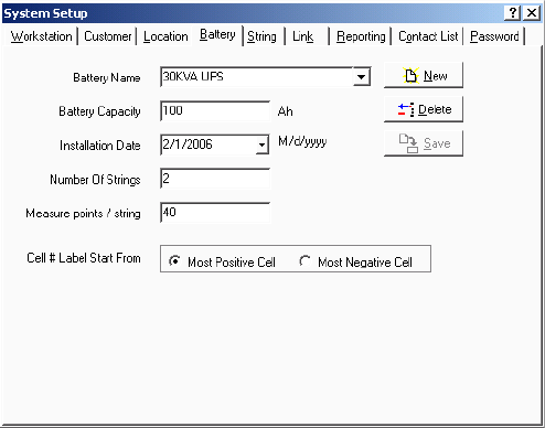
Setting Up a New MPM or BDS System
14-4
14.4. System Setup: Battery
String Status > Setup|System|Battery
The Battery dialog box assigns a battery name, cell and string parameters, and cell numbering
on the String View screen. Before completing this dialog box, confirm the correct customer
and location are selected on the Customer and Location boxes.
Figure 27. System Setup - Battery
CAUTION: Clicking the Delete button deletes all information for the displayed battery name.
All strings set up for the battery will be lost.
Battery Name (required) - Assign a unique name to the battery. Location, battery, and string
names identify the strings and hardware to which the monitor is connected.
Note: To change the battery name after monitor setup, use these Setup|System dialog boxes.
If database names do not match names in the monitor, an error message appears.
Note: You cannot have two identical battery names under the same location name. Selecting
different batteries changes the available strings on the String dialog box. This battery name
must match the battery name in the database of the connecting computer.
Battery Capacity - Type the combined capacity of all parallel strings in the battery (in
amp-hours). This is the Amp-hour rating of the battery at the eight hour rate.
Installation Date - Type the battery installation date or select from the drop-down calendar.
If desired, change the computer date format under Windows as follows.
1. Click Start|Settings|Control Panel, then click Regional Settings.
2. Click the Date tab, then select the date format from the Short Date Style drop-down menu.
3. Click OK and exit the Regional Settings dialog box.
Number of Strings (required) - Type the number of parallel strings within the battery.
Measure points / String (required) - Type the number of cells or modules per string.
Setting Up a New MPM or BDS System
14-5
Cell # Label Start From - This allows the reverse numbering of cells. Select Most Negative
Cell when the cells are numbered such that Cell 1 is the most negative.
When finished, click Save or click the next (String) tab.
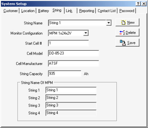
Setting Up a New MPM or BDS System
14-6
14.5. System Setup: String
String Status > Setup|System|String
The String dialog box assigns a string name, configuration, model and manufacturer names,
capacity, and MPM string names. Before completing this dialog box, confirm the correct
customer, location, and battery are selected on the Customer, Location, and Battery boxes.
The Start Cell # box for MPM changes to string # when BDS is selected. See below.
Figure 28. System Setup - String (MPM shown)
CAUTION: Clicking the Delete button deletes all information for the displayed string name.
The string name and string data will be lost.
String Name (required) - Type a name for each MPM or names for each string for a BDS.
Location, battery, and string names identify the strings and hardware to which the monitor is
connected.
Note: To change the string name after monitor setup, use these Setup|System dialog boxes. If
database names do not match names in the monitor, an error message appears.
Note: You cannot have two identical string names under the same battery name. Selecting
different strings changes selections on the Link and Reporting dialog boxes. This string name
must match the string name in the database of the connecting computer.
Monitor Configuration (required) - Select a configuration from the drop-down list. To
determine MPM hardware configuration, refer to the model number in the chart in MPM
Configuration Options.
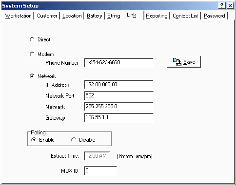
Setting Up a New MPM or BDS System
14-7
Start Cell # (MPM) (required) - Type the first cell number for the first string in the battery
being monitored by the MPM.
String # (BDS) (required) - Up to 16 DCM units can be assigned the same string number,
and the BDS can control up to eight strings. Type the string number of the DCM units to
which the information being entered applies.
Cell Model and Cell Manufacturer - Type the cell model number and manufacturer.
String Capacity - Type the capacity of the individual string (in amp-hours).
String Name of MPM (MPM only) - Assign individual string names within the MPM. The
fields available depend upon the monitor configuration selected. If the MPM has two or more
strings, such as a 2 x 24, you may type names for each string. These names appear in reports
where string names are used. The default names are String 1, 2, 3 and 4. Disabled for BDS.
When finished, click Save or click the next (Link) tab.
14.6. System Setup: Link
String Status > Setup|System|Link
The Link dialog box enables polling and sets computer to monitor connection. Before
completing this dialog box, confirm the correct customer, location, battery and string are
selected on the Customer, Location, Battery, and String boxes.
Figure 29. System Setup - Link
You must select either Direct or Modem or Network.
Direct - Select if the monitor directly connects to a computer serial port. On the
Setup|Communication box, define the COM Port at Direct Connection.
Modem - Select if the monitor connects to the computer via modem. In Phone Number, type
the phone number of the monitor that the Central computer calls (the number to which the
monitor is connected). On Setup|Communication, define the COM Port at Modem
Connection.
Setting Up a New MPM or BDS System
14-8
Network - Select if the monitor connects to the computer via network. Complete IP Address,
Network Port, Netmask and Gateway (below).
IP Address - Type the IP address of the monitor. The IP Address is specific to the
monitor (MPM or BDS Controller); it is not the IP address of the computer running the
BMDM program.
Network Port - In this box, type 502. The TCP/IP address is used when you click Send
Network Configuration on the Setup|Battery|General dialog box.
Netmask and Gateway - Type the monitor subnetmask number. Type the default
gateway number used by the monitor. If using a local LAN, the gateway number can be
left blank.
To transfer the IP, netmask, and gateway addresses to the MPM or BDS, click
Send Network Configuration on Setup|Battery|General. This button is active and
addresses can only be transferred when connected via RS-232 or modem, not network.
Polling Enable or Disable - These buttons allow polling on a per string basis, to avoid
receiving error messages when a system is off-line. Select Enable to request monitor and
battery status every 24 hours. During polling, if Auto Extract Data is selected on
Communication Setup, data is copied to the Central computer database and deleted from
monitor memory. Refer to Understanding Polling, Extraction and Backup.
Extract Time: If Extract Data by Set Time is selected on Communication Setup, type the
data extraction start time in this field.
MUX ID (required) - Possible entries are 0 to 16. A zero indicates the MPM or BDS is not
connected to a multiplexer. Device 1 to 16 corresponds to the multiplexer rear panel
connection ports. Refer to the Serial Port Multiplexer User’s Guide.
When finished, click Save or click the next (Reporting) tab.
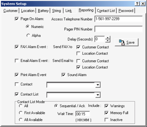
Setting Up a New MPM or BDS System
14-9
14.7. System Setup: Reporting
String Status > Setup|System|Reporting
The Reporting dialog box selects the devices the Central or Local computer contacts when
the monitor reports during continuous polling or calls in an event. Before completing this
dialog box, confirm the correct customer, location, battery, and string are selected on the
Customer, Location, Battery, and String boxes. A Service computer cannot open the
Reporting box.
Figure 30. System Setup - Reporting
Page On Alarm - Select to display the Page Report Alarm Event box on error and send alarm
notification to a pager. Click a button for the kind of pager being used: numeric or
alphanumeric.
With a numeric pager, a six digit code is sent:
Digit 1: Report Type
1 = Discharge
2 = Alarm
3 = Warning
Digits 2 to 6: String ID
For example, to report an alarm in String ID 1, the pager would display 200001.
An alphanumeric pager displays the location, battery, and string names and alarm detail.
Access Telephone Number - Type the pager phone number if numeric or the modem ID
number if alphanumeric. If using an alphanumeric pager, use an access number that has a
TAPI interface that communicates using a modem instead of voice. For example, SkyPage's
access number is (800) 759-6366. This can also be the TAPI phone number for cellular
phones if the cell phone supports text messaging.
Pager PIN Number - Type the pager private ID (PIN) number if needed or the cell phone
number if using text messaging.
Setting Up a New MPM or BDS System
14-10
Delay (Seconds) - If using a numeric pager, type the delay in seconds before the numeric
message is sent.
Fax Alarm Event - Select to display the Fax Report Alarm Event box on error and send
alarm notification to a fax machine. Check a box to direct the report to the Customer
Contact or Location Contact. The system dials the fax telephone number on the Customer
or Location dialog box.
Email Alarm Event - Select to display the Email Alarm Event box on error and send alarm
notification via email. Check a box to direct the report to the Customer Contact
or Location Contact. The system sends to the email address on the Customer or Location
dialog box. Confirm global Disable Email is not checked on the Email Setup dialog box.
Print Alarm Event - Select to display the Print Report Alarm Event box on error and send
alarm notification to a printer. To select a default printer, at the String Status screen, click
File|Printer Setup. If alarms do not print when received, change the Spool Data Format
setting. On Windows, click Start|Settings|Printers. Right click the icon for your printer, then
click Properties|Details|Spool Settings. At Spool Data Format, select EMF or RAW.
Sound Alarm - Select to enable an audible alarm for this string when an alarm event occurs.
Select the alarm sound by clicking Select Sound under Setup|Preferences. To enable alarm
reporting and alarm sounds, confirm global Disable Alarm Reporting and Disable Sound are
not selected on the Preferences dialog box.
Contact - To contact a person from any contact list, select the check box and choose a name
from the drop-down list. This name is in addition to names in a group contact list.
Contact List - To contact a group of people from a contact list, select the check box and
choose a group contact name from the drop-down list. Members of the group will be
contacted based on the Contact List Mode.
The Contact List Mode area has the following selections.
All - Upon an alarm event, contact all names in the contact list, whether on-duty or off.
First Available - Upon an event, contact the first name on-duty in the contact list. No further
action is taken.
All Available - Upon an event, contact all names on-duty in the contact list. No further action
is taken.
Sequential / Ack - Upon an event, contact the first name on-duty in the contact list and wait a
preset time for acknowledgement. If none is received, contact the next available person in the
list and wait for acknowledge. Continue and repeat the sequence until acknowledgement is
received or until the list is gone through one time.
Note: You must select Acknowledge in the Alarm Button area on Setup|Battery|General.
Wait Time - Click the box and type a time (in hours and minutes) that the program waits
before calling the next person when Sequential/Ack is selected.
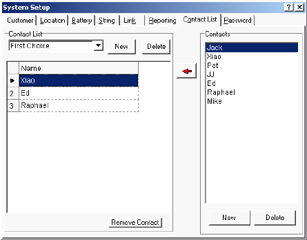
Setting Up a New MPM or BDS System
14-11
Include Warnings, Memory Full and Inactive - Select these check boxes to contact and
require acknowledgement when these events occur and Sequential/Ack is selected. If not
selected, event notice is sent only once and no acknowledgement is required.
When finished, click Save or click the next (Contact List) tab.
14.7.1. Using a Cell Phone for Text Messaging
You may use a cell phone to receive text messages. Type your provider's TAP telephone
number in the Access Telephone Number field and type your cell phone number in the Pager
PIN Number field. You can find cell phone provider TAP telephone numbers at
www.notepager.com/tap-phone-numbers.htm. Not all cell phone providers offer this text
messaging service. The Email or Pager fields can also send text messages to a cell phone.
14.8. System Setup: Contact List
String Status > Setup|System|Contact List
The Contact List dialog box selects persons to be contacted during an alarm reporting event,
in addition to those listed on the Customer and Location dialog boxes.
Figure 31. System Setup - Contact List
Contact List - Each Contact List (group) name contains a group of persons to contact. To
create a new Contact List name, click New in the left Contact List panel. The Contact List
Name dialog box appears. At List Name, type a name, then click OK.
Delete (left panel) - To remove a contact list (group) name from the list, click a name from
the drop-down Contact List and click Delete. This permanently deletes the contact list.
Delete (right panel) - To remove a person's name from the list of potential contacts, click a
name on the right Contacts list and click Delete. This permanently deletes the contact.
Remove Contact - To remove a person's name from the group Contact List, click the
person's name to highlight it, then click Remove Contact.
Sort Names - To move a person's name up or down the list to change call priority, click and
drag the number before the name up or down the list onto another number.
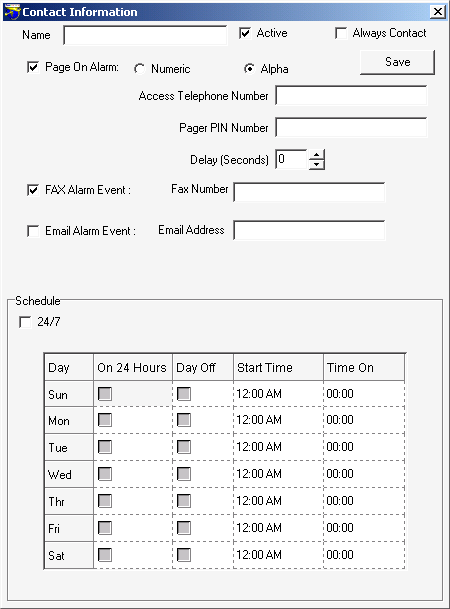
Setting Up a New MPM or BDS System
14-12
Contacts - To type persons' names to add to a list of potential contacts, click New on the
right panel on the Contact List dialog box to open the Contact Information box.
Figure 32. System Setup - Contact Information
String Status > Setup|System|Contact List|New (on right panel)
Use the Contact Information dialog box to add names to the list of potential contacts.
Name - Type the contact person's name.
Active - Do not select if the person is unavailable. For example, the person is on vacation.
Always Contact - Select to always contact the person, regardless of settings elsewhere. The
Active check box must be selected.
Setting Up a New MPM or BDS System
14-13
Page On Alarm - Select to display the Page Report Alarm Event box on error and send alarm
notification to a pager. Click a button for the kind of pager being used: numeric or
alphanumeric.
With a numeric pager, a six digit code is sent:
Digit 1: Report Type
1 = Discharge
2 = Alarm
3 = Warning
Digits 2 to 6: String ID
For example, to report an alarm in String ID 1, the pager would display 200001.
An alphanumeric pager displays the location, battery, and string names and alarm detail.
Access Telephone Number - Type the pager phone number if numeric or the modem ID
number if alphanumeric. If using an alphanumeric pager, use an access number that has a
TAPI interface that communicates using a modem instead of voice. For example, SkyPage's
access number is (800) 759-6366.
Pager PIN Number - Type the pager private ID (PIN) number if needed.
Delay (Seconds) - If using a numeric pager, type the delay in seconds before the numeric
message is sent.
Fax Alarm Event - Select to send alarm notification to a fax machine. At Fax Number, type
the fax machine phone number the system will dial.
Email Alarm Event - Select to send alarm notification to the person via email. Type an
address in the Email Address box. Confirm Disable Email is not checked on the Email Setup
dialog box.
Use the Schedule area to build the time on / off for the person.
24/7 - Select if the person is on call 24 hours a day, 7 days a week or, in the Sunday through
Saturday grid, you may select the following:
On 24 Hours - Select if the person is on call the entire day.
Day Off - Select if the person is not available that day.
Start Time - If the person is available part of the day, click the Start Time field and type
the time availability starts. You may press Enter to step to the Time On field.
Time On - Click this field and type the number of hours the person is available. You may
press Enter to step to the next Start Time field.
When finished, click Save to return to the Contact Lists dialog box. To edit information after
saving, double-click the name in the right side Contacts list.
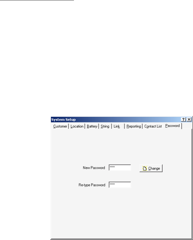
Setting Up a New MPM or BDS System
14-14
Add Names to Contact List - To add people to a Contact List, first select a group name from
the drop-down Contact List. Next, click a person's name in the Contacts list on the right, then
either click the red arrow or right click the name and select Add to List. The name appears in
the list on the left.
If you want to add new names to the Contact or Contact List boxes on the Reporting dialog
box, click the Reporting tab. If not and you are finished, click Save and close the dialog box.
If you want to change the password, click the Password tab.
14.9. System Setup: Password
String Status > Setup|System|Password
Use the Password dialog box to change the System Setup password. If the password is
incorrect, you can view protected screens but cannot change parameters. The Password tab
appears only if the correct password is entered when Setup|System is selected.
Figure 33. System Setup - Password
New Password - To change the System Setup password, type the new password in
the New Password and Re-type Password boxes. The password may be up to eight
alphanumeric characters long. Click Change. The new password is now in effect.
Record the new password for reference. If the password is lost, you must contact Albér.

Synchronizing Using Check Settings
15-1
15. Synchronizing Using Check Settings
The location, battery, and string names are key for letting a computer connect to a monitor; all
names must match or connection fails. Typically, a Central computer assigns names into the
monitor, and Check Settings uploads to the computer any test times, alarm thresholds, and data
settings put into the monitor during commissioning. Synchronizing is the process of uploading
using Check Settings and must be done using a Central computer connected to the monitor via
RS-232, modem or network. An upload for a BDS must be done twice. After a system is
synchronized, it can be placed into service. Refer to Check Settings Screens for screen shots.
Note: If a system fails to synchronize, complete the Battery Setup dialog boxes.
Before synchronizing, you should understand the Upload, Close, Recheck, and Send Time
buttons on the Check Settings dialog boxes. The Battery Setup password enables Send Time and
Upload.
Upload Button - To transfer settings between the computer and monitor, click Upload. The
data transferred depends on computer type. A Central computer sends the location, battery,
and string names, string ID, current date and time to the monitor, and the monitor sends all
other settings to the computer database. Using a Local or Service computer, the monitor
transfers setup to the computer, but names, date and time are not sent to the monitor. You
need to click Upload on only one Check Settings box, usually Check Settings|General. If you
are uploading a BDS, repeat the Upload a second time.
Close Button - After transferring settings using Upload, to close Check Settings, click Close.
Recheck - Clicking Recheck is the same as clicking Setup|Check Settings. Recheck reloads
settings from the database and monitor into the Check Settings boxes.
Send Time - This button sends the date and time from the computer to the monitor without
affecting other settings.
String Status > Connection
Complete the Preferences, Communication Setup, and System Setup dialog boxes then, on the
String Status screen, highlight the location name you want to synchronize and click Connection.
System Connects Normally - If connection is established, the names match, and no error
messages appear, click Setup|Check Settings|General. After setup data appears in the In Database
and In Monitor columns, click Upload to transfer from monitor to computer database. After
upload, click Close. All data is transferred, and the site is ready to go into service.
"String needs to be set up" Message - If the system connects, but "This string needs to be set
up" appears, the location, battery or string names do not match. You must upload the monitor
settings. Click OK at the message, select Setup|Check Settings|General, then click Upload as
described in the preceding System Connects Normally paragraph.
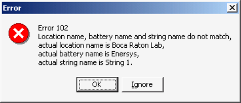
Synchronizing Using Check Settings
15-2
Note on Network Settings - Network parameters do not upload using Check Settings|General.
To change the IP Address, Netmask or Gateway, use Setup|System|Link. To send the existing or
changed IP, Netmask or Gateway address to the MPM or BDS, click Send Network
Configuration on Setup|Battery|General. This button is active and the addresses can be sent only
when the computer is connected to the BDS or MPM via RS-232 or modem, not via network.
Note on using a Local or Service computer - With a Local or Service computer, the monitor
transfers setup to the computer, but names, date and time are not sent to the monitor. "This string
needs to be set up" will continue to appear until you synchronize with a Central computer.
System Does Not Connect (Error 102) - When connecting, the "Location name, battery name
and string name do not match" message may appear.
Figure 34. Connection Error Message
Extra or missing spaces and hyphens affect names. Click OK to return to String Status or click
Ignore to display Check Settings. If names have been assigned in the monitor, either:
1. Use Setup|System to change the names in the computer database to match the names in
the error message box, or
2. If on-site with the equipment, clear the existing names in the monitor and enter new
names as described below.
3. After correcting the problem, attempt to connect, then upload using Check Settings.
Clear Existing Names (On-site)
MPM - To clear names in an MPM, press the MPM Alarm Reset switch while cycling power
off then on. Release the switch after the MPM front panel LEDs sequence from left to right.
This reset also disables the alarms and auto call-out function, resets the MPM hardware
password to the default, and clears all data in the monitor, including active alarms.
BDS - To clear names in a BDS, press the BDS Controller Alarm Reset switch while cycling
power off then on. Release the switch after the BDS front panel Status LED flashes rapidly.
This reset also disables the alarms and auto call-out function and resets the BDS hardware
password to the default. Optionally, instead of pressing the reset switch, you can clear the
names on the Diagnostics|Memory screen.
Synchronizing Using Check Settings
15-3
15.1. Connecting With a Service Computer
This section describes how to connect to a monitor when site details are not known.
Connecting a Service Computer via Modem - Using a Service computer, type the site
telephone number and MUX ID (if a multiplexer is used) under Setup|System|Link. If using a
BDS, also type the String ID number and the BDS monitor configuration under
Setup|System|String. Click Connection. Check Settings|General appears. Click Upload to
synchronize settings between the monitor and Service computer database, then click Close.
String View displays all real time data.
Connecting a Service Computer via Network - Using a Service computer, type an IP
address under Setup|System|Link. If using a BDS, also type the String ID number and the
BDS monitor configuration under Setup|System|String. Click Connection.
Check Settings|General appears. Click Upload to synchronize settings between the monitor
and Service computer database, then click Close. String View displays all real time data.
Connecting a Service Computer via RS-232 - Using a Service computer, click Connection.
Check Settings|General appears. Click Upload to synchronize settings between the monitor
and Service computer database, then click Close. String View displays all real time data.
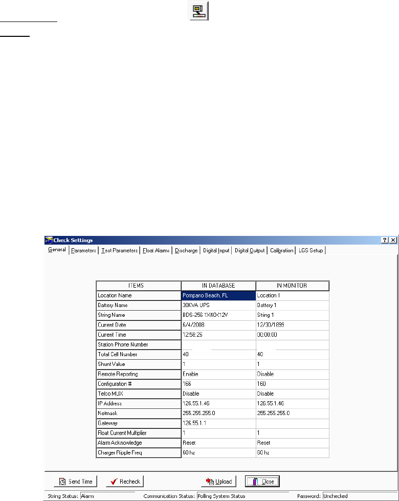
Check Settings Screens
16-1
16. Check Settings Screens
Active check: String Status > Connection then Setup|Check Settings|dialog box
Offline: String Status > View|Offline|Setup|Check Settings|dialog box
The Check Settings dialog boxes display settings in the BMDM database and MPM or BDS
nonvolatile memory. Use Check Settings to synchronize a battery location. On a Local, Central or
Service computer, when String View displays an active connection, you may click
Setup|Check Settings to view Check Settings setup, send the time and date, and upload settings.
You cannot change settings using these boxes. Offline you can view the settings, but the Send
Time, Recheck and Upload buttons are not active.
Open the Check Settings dialog boxes. When MPM and BDS boxes are similar, only one figure is
shown below. For item definitions, refer to Synchronizing Using Check Settings and
Programming Battery Setup for the BDS or MPM.
The Check Settings|General dialog box for MPM and BDS is shown below. Network parameters
do not transfer from Check Settings. To change the IP Address, Netmask or Gateway, refer to
Synchronizing Using Check Settings.
Figure 35. Check Settings - General (MPM / BDS)
Note: When you click Upload on Check Settings, the Location Name, Battery Name, and
String Name in the monitor do not overwrite the names in the computer database. However, when
a Central computer is used to download to the monitor, these three names are overwritten in the
monitor when Send is clicked on Battery Setup.
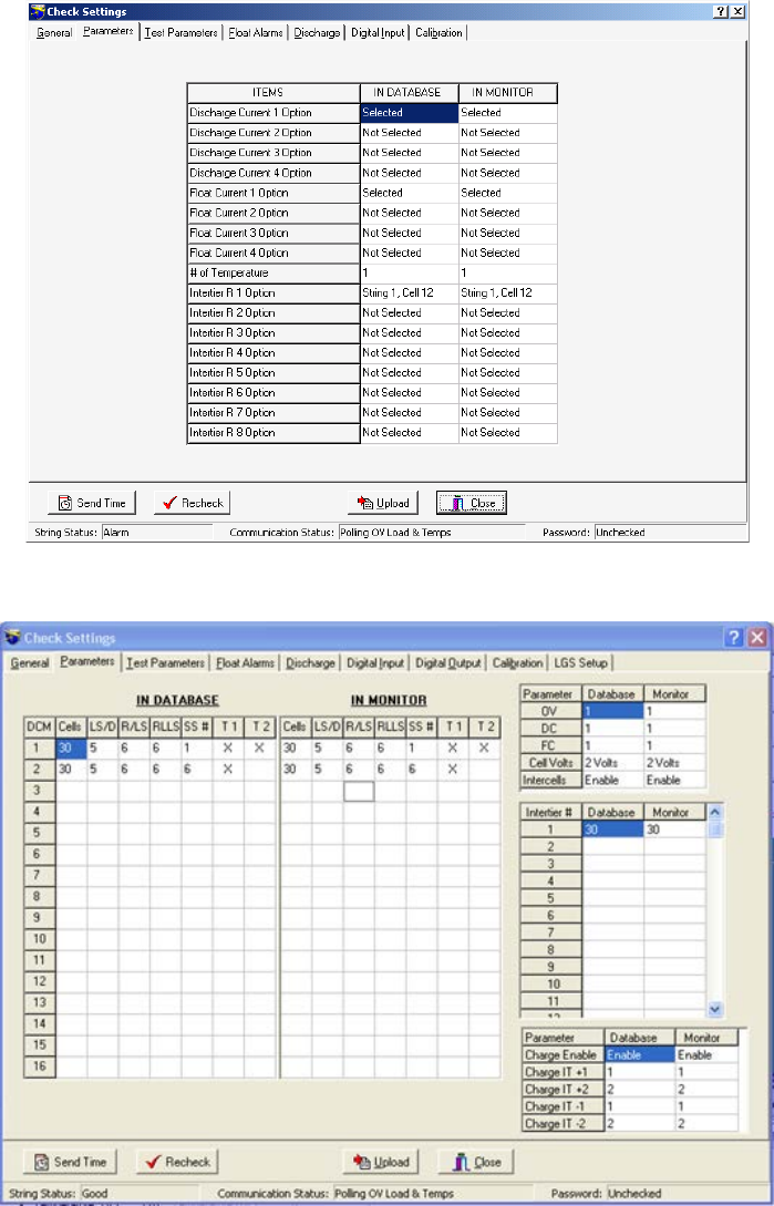
Check Settings Screens
16-2
The Check Settings|Parameters dialog boxes for the MPM and BDS are shown below.
Figure 36. Check Settings - Parameters (MPM)
Figure 37. Check Settings - Parameters (BDS)
For BDS setup, the system shows information based on string one only.
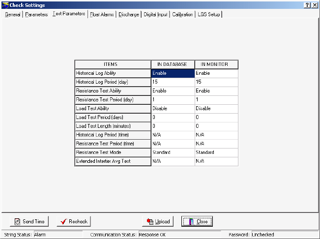
Check Settings Screens
16-3
The Check Settings|Test Parameters dialog box for the MPM and BDS is shown below.
Figure 38. Check Settings - Test Parameters (MPM / BDS)
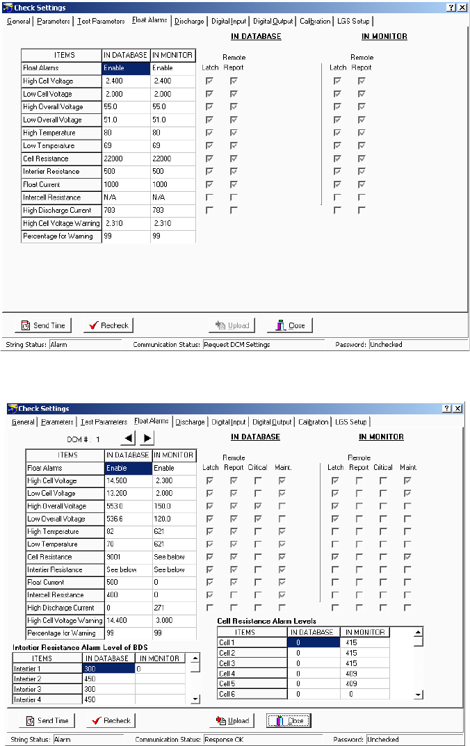
Check Settings Screens
16-4
The Check Settings|Float Alarms dialog boxes for the MPM and BDS are shown below.
Figure 39. Check Settings - Float Alarms (MPM)
Figure 40. Check Settings - Float Alarms (BDS)
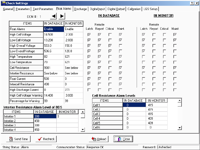
Check Settings Screens
16-5
Figure 41. Check Settings - Float Alarms (BDS)
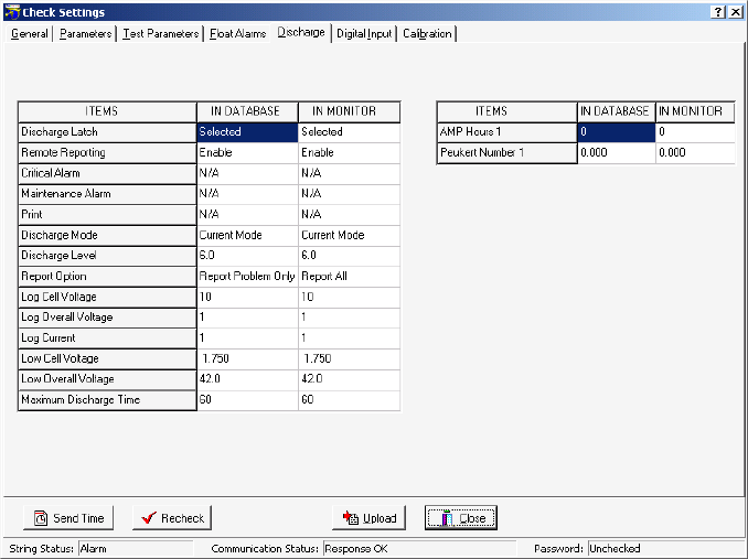
Check Settings Screens
16-6
The Check Settings|Discharge dialog box for the MPM and BDS is shown below.
Figure 42. Check Settings - Discharge (MPM / BDS)
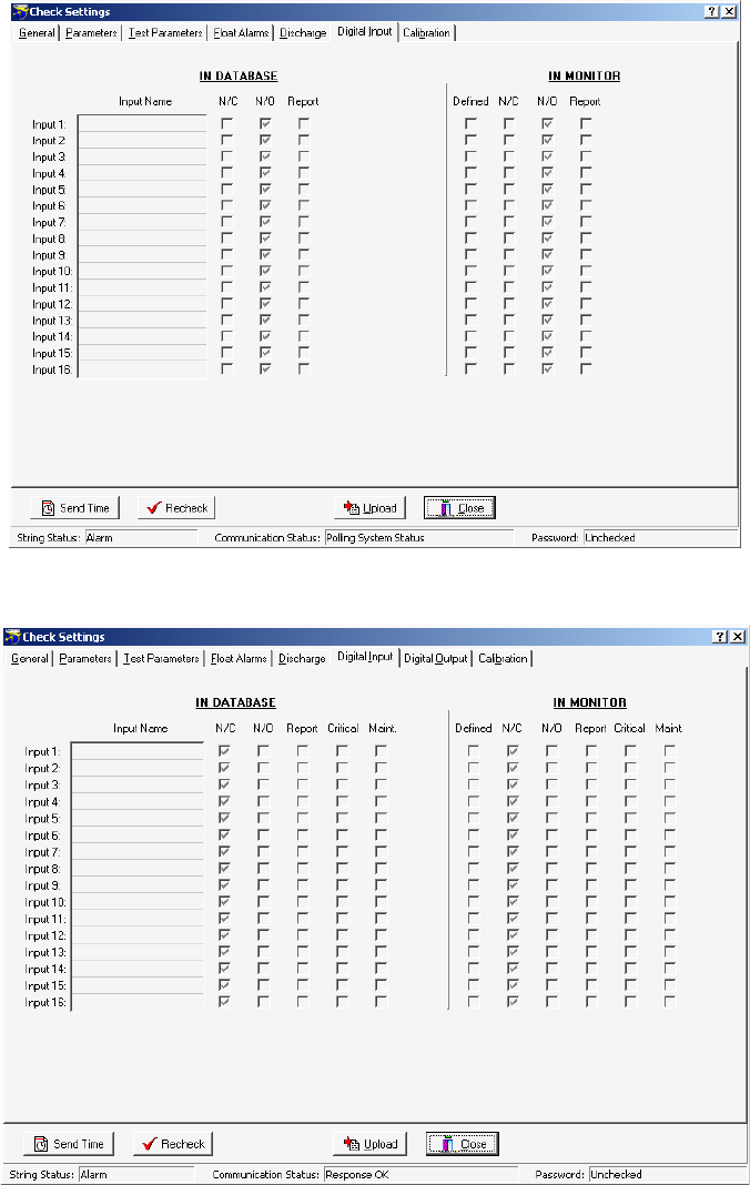
Check Settings Screens
16-7
The Check Settings|Digital Input dialog boxes for the MPM and BDS-256 are shown below. The
BDS Digital Input tab and dialog box are available only for String 1 on a BDS. The tab
disappears if a string other than 1 is selected. Not available for the BDS-40.
Figure 43. Check Settings - Digital Input (MPM)
Figure 44. Check Settings - Digital Input (BDS)
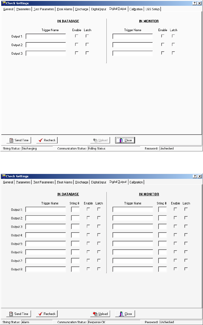
Check Settings Screens
16-8
The Check Settings|Digital Output dialog boxes for the MPM and BDS-256 are shown below.
The Digital Output tab and dialog box disappear if a BDS-40 is selected.
Figure 45. Check Settings - Digital Output (MPM)
Figure 46. Check Settings - Digital Output (BDS/256)
For BDS setup, the system shows information based on string one only.
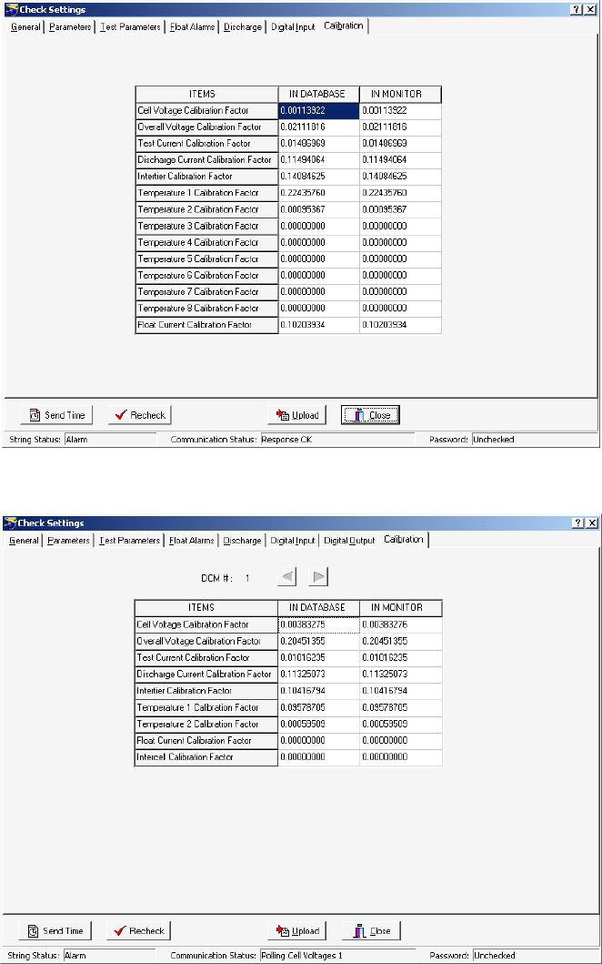
Check Settings Screens
16-9
The Check Settings|Calibration dialog boxes for the MPM and BDS are shown below. The BDS
Calibration dialog box reports the Intercell Calibration Factor in addition to the other factors. The
arrow buttons let you upload other DCM's.
Figure 47. Check Settings - Calibration (MPM)
Figure 48. Check Settings - Calibration (BDS)
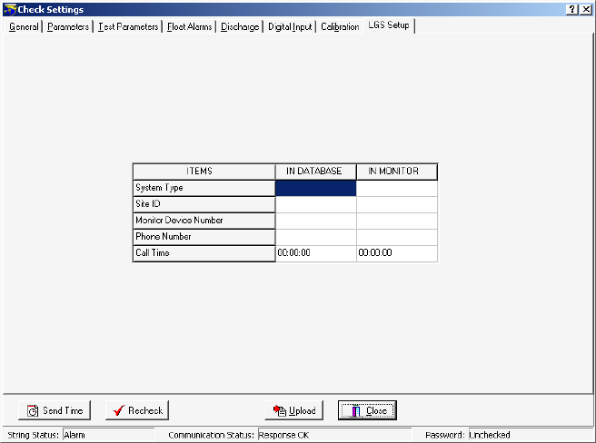
Check Settings Screens
16-10
The Check Settings|LGS dialog box for the MPM and BDS is shown below.
Figure 49. Check Settings - LGS (MPM / BDS)
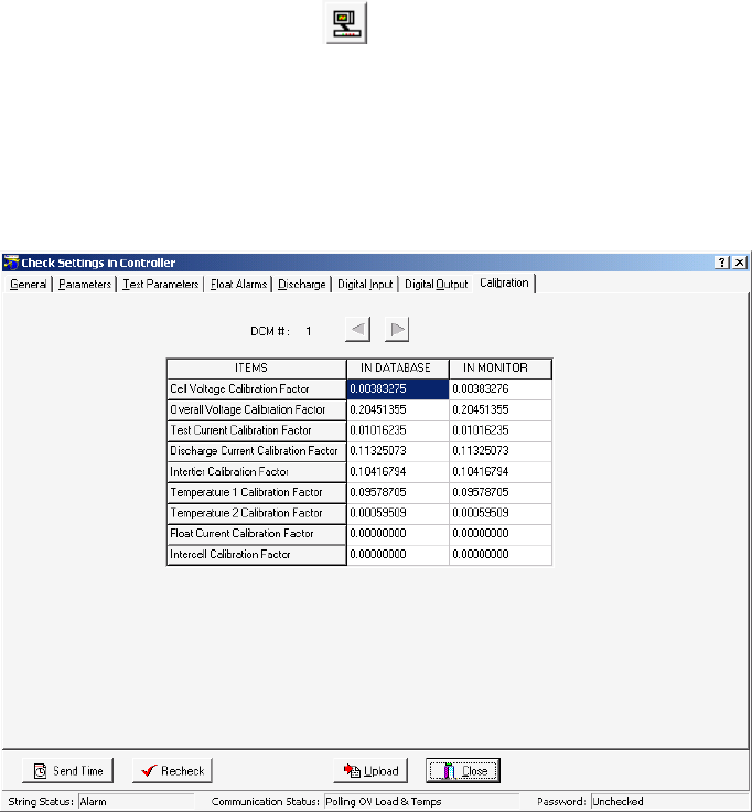
Check Settings Screens
16-11
16.1. Check Settings Screens in Controller
BDS Only: String Status > Connection then <CTRL>Setup|Check Settings|dialog box
A second series of Check Settings boxes for diagnostics is available for the BDS. These
Check Settings in Controller boxes retrieve data from the BDS Controller instead of the
DCM. To open Check Settings in Controller, at String View, hold down the CTRL key while
selecting Setup|Check Settings.
A typical dialog box, Check Settings in Controller|Calibration for the BDS, is shown below.
Figure 50. Check Settings in Controller - Typical Screen (BDS)

Programming Battery Setup for the MPM
17-1
17. Programming Battery Setup for the MPM
From String Status, click Connection to display the String View screen.
String View > Setup|Battery|dialog box
After completing Preferences, Communication Setup, and System Setup, complete the Battery
Setup dialog boxes. To open Battery Setup, on the String Status screen, highlight the location
name, then click Connection. After computer to monitor communication is established, the String
View screen appears. To perform battery setup, select Setup|Battery to display the dialog boxes.
Password - If the Battery Setup boxes are protected, type the Battery Setup password and click
OK. This password closes when communication ends. If the password is incorrect, the
Battery Setup boxes appear, but the Send button is inactive.
To change the location, battery or string names after the monitor is set up and communicating,
use the Setup|System dialog boxes.
Send Button and Close Button - On the Battery Setup boxes, the Send button transfers settings
to the monitor. On Battery Setup|Test Parameters, the Historical Log, Resistance Test, and
Load Test settings are sent only if changed. You may complete all dialog boxes before clicking
Send. Clicking Send on any box transfers settings from all boxes. Changes are not saved or sent if
you only click Close.
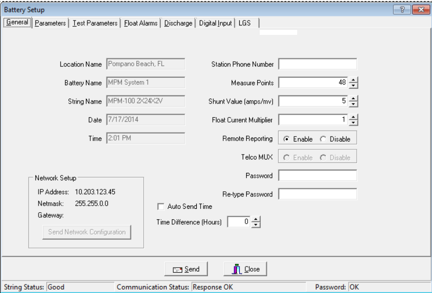
Programming Battery Setup for the MPM
17-2
17.1. Battery Setup: General (MPM)
String View > Setup|Battery|General
The following appear on the General dialog box.
Figure 51. Battery Setup - General (MPM)
Location Name, Battery Name, String Name - Location, battery, and string names identify
the strings and hardware to which the monitor is connected. Make sure databases have the
same names to ensure proper connection. Location, battery, and string names can only be
changed under Setup|System.
Date, Time - The date and time of the computer. When you send a new configuration to the
monitor, it sends this date and time.
Station Phone Number - Type the telephone number of the Central computer the MPM
monitor calls when a system goes into alarm or discharge.
Measure Points - This is defined by Monitor Configuration on Setup|System|String.
Normally, do not change the Measure Points number; however, you may change it for custom
configurations (BDS only) not listed on System Setup|String.
Note: Do not change the Measure Points number for multi-string configurations. If you enter
a lower cell number for a configuration of 2x24, for example, only the total cell count for the
second string changes.
Shunt Value - Type the shunt rating in amps per millivolt. For example, for a shunt of
600 amps/100mV, type 6. (600 amps/100mv = 6 amps/1mv.) This value must be an integer.
Programming Battery Setup for the MPM
17-3
Float Current Multiplier - When a series of batteries is connected with more than one cable,
it may not be possible to get the float current sensor around all the cables. In this case, you
may connect the sensor around one of the cables and set the Float Current Multiplier for the
total number of cables. The connecting cables must be of equal length.
Remote Reporting Enable and Disable - Globally enables or disables the monitor remote
reporting function. For a parameter to report on alarm, do not select the global Disable Alarm
Reporting on Setup|Preferences, and select Remote Reporting on Setup|Battery|Float Alarms
or Setup|Battery|Discharge.
Telco MUX - Not available for the MPM.
Password - To change the battery setup password, type the new password in the Password
and Re-type Password boxes. The password may be up to five alphanumeric characters long.
IP Address, Netmask and Gateway - Displays the IP address, netmask, and gateway typed
on Setup|System|Link.
Send Network Configuration - Click this button to send the IP address, netmask, and
gateway to the MPM. The MPM must have the internal network option installed. This button
transfers addresses only when MPMs are connected via RS-232 or modem, not network.
Auto Send Time - Check this box to have the time of day sent from the computer to the
hardware during autopolling and data extraction.
Time Difference (Hours) - This spin box lets you compensate for any plus or minus time
difference between the computer and hardware installation locations. When the computer
sends the time of day to the hardware, either during autopolling or Check Settings upload, the
time is automatically adjusted.
Alarm Button - If Sequential/Ack is selected on the System Setup Reporting dialog box,
select Acknowledge so the monitor notifies the computer that acknowledgement was sent
and received. This stops sequential calling but does not reset the alarm. Select Reset if
Sequential is not selected.
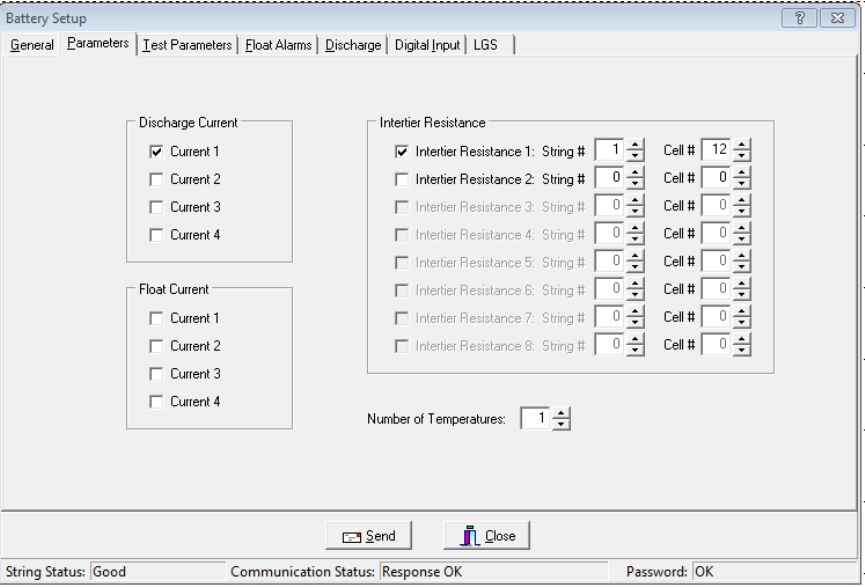
Programming Battery Setup for the MPM
17-4
17.2. Battery Setup: Parameters (MPM)
String View > Setup|Battery|Parameters
On Parameters, select the hardware and parameters that will be polled and displayed.
Figure 52. Battery Setup - Parameters (MPM)
Discharge Current - You can define up to four discharge current channels, but only one
current channel per string is allowed. If the configuration is one string, then only one current
channel may be used. Only Current 1 can trigger the recording of a discharge if Current Mode
is selected on Setup|Battery|Discharge.
Intertier Resistance - The MPM can monitor up to four strings. If selecting an Intertier
Resistance option, at String #, type the number of the string that contains the intertier. At
Cell #, type the number of the cell that is before the intertier. The intertier resistance must be
selected in numerical order.
Number of Temperatures - You may select up to eight probes to monitor ambient or
electrolyte temperature.
Float Current - The MPM can monitor up to four float current values, displayed on the
Cell Voltage screen. Set the value in the High Float Current field on Setup|Battery|
Float Alarms. Actual current that exceeds set value appears in red on the Cell Voltage screen
and causes an alarm. The float charging current probe (FCCP) may take 25 minutes to
stabilize after a power change. Refer to the Multitel, Inc. Float Charging Current Probe
User's Manual.
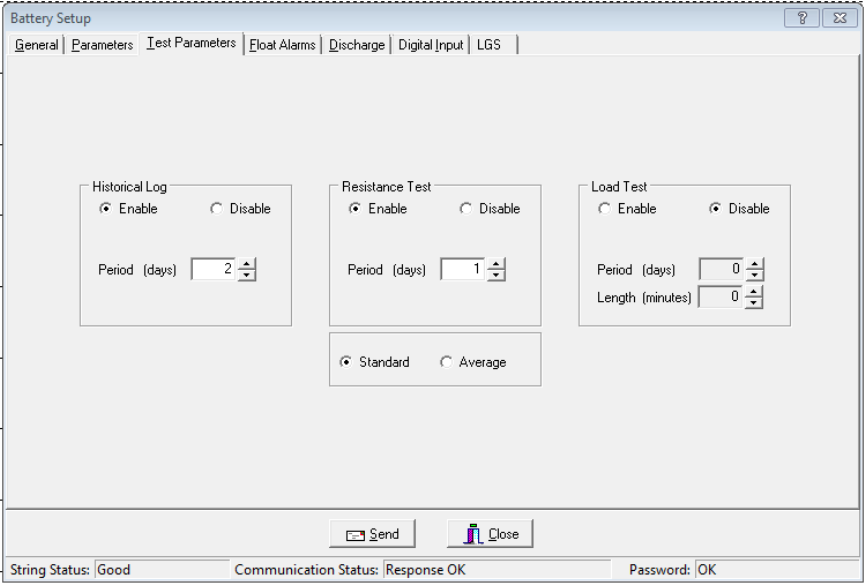
Programming Battery Setup for the MPM
17-5
17.3. Battery Setup: Test Parameters (MPM)
String View > Setup|Battery|Test Parameters
The following appear on the Test Parameters dialog box.
Figure 53. Battery Setup - Test Parameters (MPM)
Logging / R-Test Time Mode area - Click the Absolute Date and Time option button to
specify the exact day of the month, from 1 to 28 (29, 30 and 31 are not used), and time the
historical log is updated and the resistance test is performed. Click the Day Interval button to
specify how often (in days) the historical log is updated and the resistance test is performed.
Historical Log area - Click Enable to activate, then complete Period (days) and
Period (time) described below. Specify how often in days or the date and time the voltages,
currents, and temperatures are recorded in the history log.
Period (days) and Period (time) - Either select how often the historical log is updated, or
select the day of the month and time the log is updated.
Resistance Test area - Click Enable to activate, then complete Period (days) and
Period (time) described below. Specify the resistance test interval in days or date and time. If
set to 30 days, resistance is tested every 30 days starting at 12:00 A.M. (midnight). If you
program the Load Test for the same interval as the Resistance Test, the Resistance Test is
delayed three days.
Period (days) and Period (time) - Either select how often the resistance test is performed, or
select the day of the month and time the test is performed.
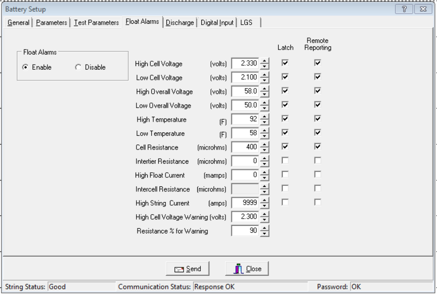
Programming Battery Setup for the MPM
17-6
Standard or Average - Normally select Standard. If the charger employs digital control of
battery voltage, which causes voltage fluctuation, select Average.
Load Test - Specify load test interval in days and length of the load test in minutes. Load test
activates a relay that shuts down the charger, if connected, and enables tracking of the
discharge. If set to 30, load test is done every 30 days starting at 12:00 A.M. See Resistance
Test (above).
17.4. Battery Setup: Float Alarms (MPM)
String View > Setup|Battery|Float Alarms
The following appear on the Float Alarms dialog box.
Figure 54. Battery Setup - Float Alarms (MPM)
Float Alarms Enable or Disable - Global control of all float alarms for local alarm status
and alarm contact activation. Select Enable for the call-out of float alarms and digital input
alarms. When Disable is selected, the MPM Alarm Disable LED is lit, and the String Status
column on the String Status screen indicates Alarms Disabled.
Cell Resistance Threshold - Global applies the alarm level in the Cell Resistance
(microhms) field to all cells. Individual and Input Level sets alarm levels on a cell basis
using the Cell Resistance Alarm Levels box.
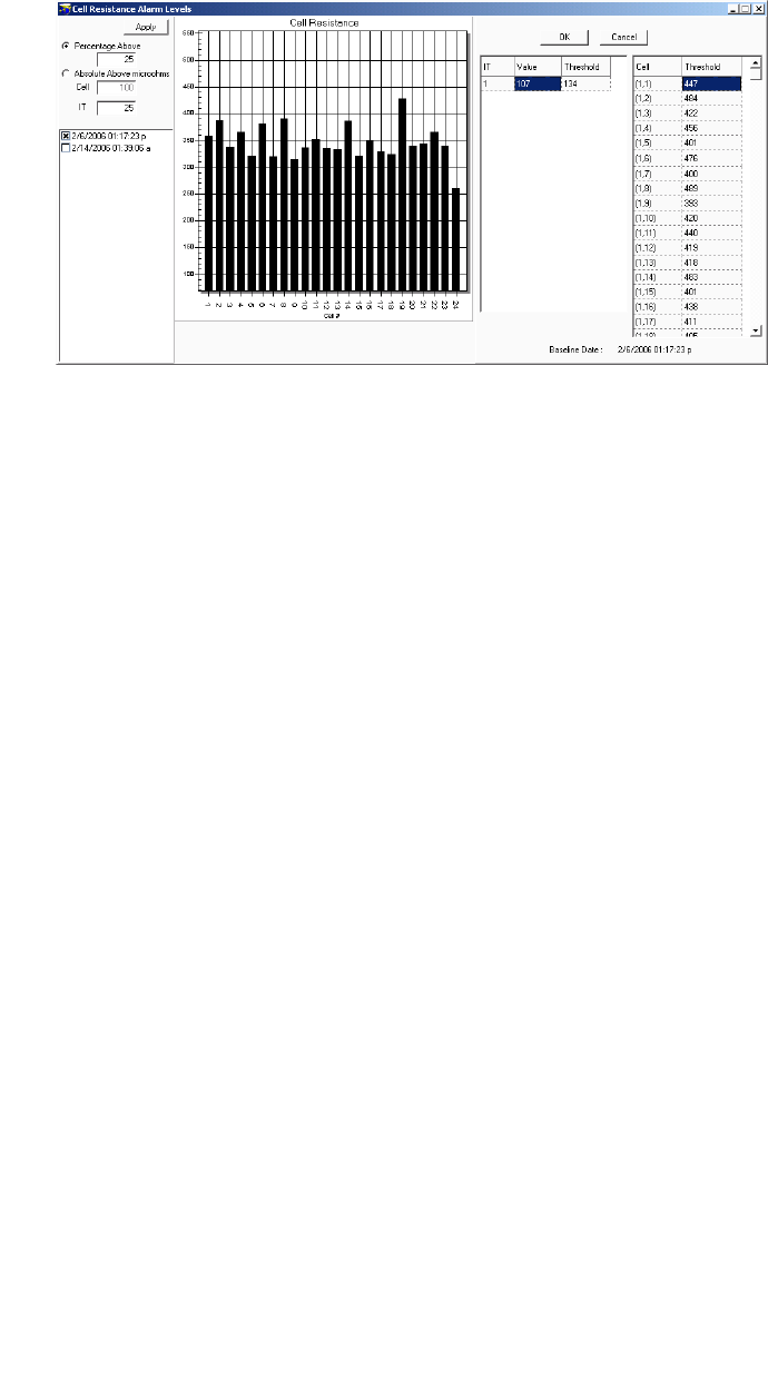
Programming Battery Setup for the MPM
17-7
Figure 55. Cell Resistance Alarm Levels Setup (MPM)
Cell Resistance Alarm Levels box - To set Alarm Levels on a cell basis, click Individual and
Input Level and select options on this box.
Percentage Above - Sets the cell alarm level a percentage above the selected dataset
levels. Type a value (1 to 99) in the Percentage Above field.
Absolute Above (Microhms) - Sets the cell alarm level a numeric value above the
selected dataset levels. Type a value (1 to 99) in microhms in the Absolute Above field.
Date area check boxes - Click one dataset date in this area on which to base alarm
levels. The system stores the date of the baseline data and displays it on the lower right
after the Apply button is clicked.
Apply - Click apply to apply selected levels to the cells. The values appear in the
Threshold column. If you do not want to edit individual cell levels (see below), click OK.
Cell, Intertier and Threshold columns - To edit individual cell or intertier alarm levels
in the Threshold column, click the value and type a new value. After editing, click OK.
Note: Values are not saved until Save or Send is clicked on the Float Alarms or another
Battery Setup box.
Alarm Thresholds - For high and low cell voltage, overall voltage, temperature, resistance,
and current, select violation threshold values that activate an alarm during a float condition.
These thresholds are deactivated for 30 minutes following a resistance test. If a discharge
occurs, the alarms are disabled until the overall voltage recovers to a value above the low
threshold.
High Cell Voltage Warning (volts) - Type a value between the Low Cell Voltage and High
Cell Voltage levels. This setting affects the bar graph colors on the Cell Voltage String View
screen. During normal float condition, the bar colors change as follows:
High Violation ................... Red
Warning ............................ Blue
Normal .............................. Green
Low Violation .................... Yellow
Out of Range Values ........ Maroon
Negative Cell Voltage ....... Black
Bar Colors for all
Normal and
Violation Types
Programming Battery Setup for the MPM
17-8
Percentage for Warning - Determines the violation threshold that causes a Warning battery
status. The value entered is a percentage of the internal resistance alarm. For example, if the
internal resistance alarm is set to 100 microhms and the percentage for warning is 75%, the
system issues a warning when the internal resistance is between 75 and 100 microhms. When
the value exceeds 100 microhms, the system issues an alarm. Warning status is displayed
only on the String Status and Historical Events screens, not on the Alarms screen.
<-----Normal-----75%<-----Warning----->100%-----Alarm----->
Latch - When selected, the alarm contact stays energized until manually reset. If not selected,
the alarm contact de-energizes when the alarm condition clears.
Remote Reporting - When selected, causes the monitor to report the alarm. When not
selected, call-out is disabled for that parameter. You must select this option and Remote
Reporting Enable under Setup|Battery|General to enable the call out function and to display
Alarm Detail on the Historical Events screen during polling.
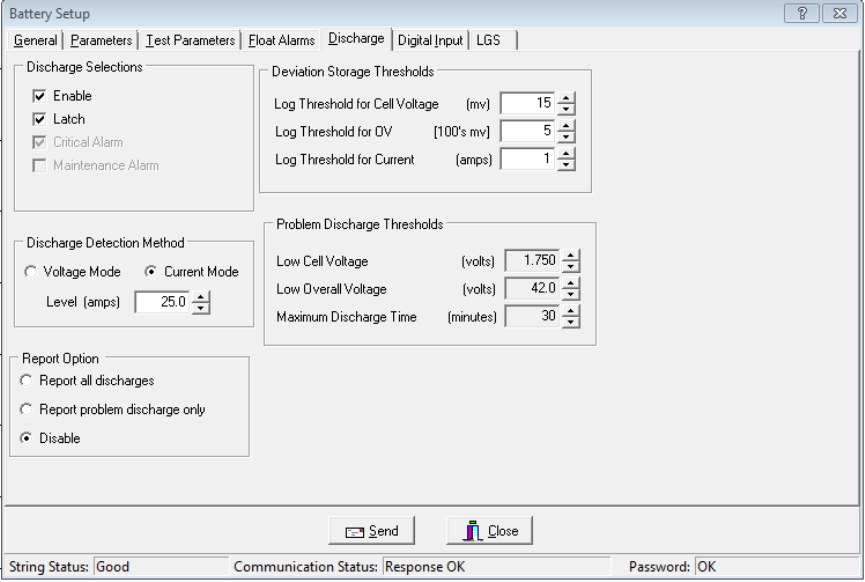
Programming Battery Setup for the MPM
17-9
17.5. Battery Setup: Discharge (MPM)
String View > Setup|Battery|Discharge
The following appear on the Discharge dialog box.
Figure 56. Battery Setup - Discharge (MPM)
Discharge Selections Area:
Enable - Select to let the monitor capture and store discharge data. If not selected, the
MPM does not log discharges.
Latch - When selected, the alarm contact stays energized until manually reset. If not
selected, the alarm contact de-energizes when the discharge condition clears.
The Critical Alarm and Maintenance Alarm options do not apply to the MPM.
Discharge Detection Method Area:
Select Voltage Mode or Current Mode, then set the threshold Level in volts or amps to
activate data logging during a discharge. When the voltage goes below the set level or the
current exceeds the set level, the monitor begins recording cell voltages, discharge
current, and overall voltage, based on the Deviation Storage Thresholds (described later).
Only one temperature sample is stored at the beginning of the discharge.
Programming Battery Setup for the MPM
17-10
Voltage mode allows data recording during recharge, since data logging does not stop
until the voltage goes above the threshold. If measuring discharge current, use
Discharge Current Mode as a reliable source of trigger.
In current mode, the monitor triggers only on Current Channel 1 selected on
Setup|Battery|Parameters. To enable this mode, you must define the Current Channel on
the Setup|Battery|Parameters dialog box.
Report All Discharges - If selected, the monitor reports all discharges to the Central
computer. You must enable Remote Reporting on Setup|Battery|General.
Report Problem Discharge Only - If selected, the monitor reports only discharges that
exceed voltage or time values set in Problem Discharge Thresholds (described later) to the
Central computer.
Disable - If selected, stops the MPM from reporting a discharge.
Deviation Storage Thresholds Area - Log Threshold for Cell Voltage, Log Threshold for
OV (Overall Voltage), and Log Threshold for Current - When the voltage or current
changes by the amounts in these boxes, the event is recorded. For most applications, use
10mv for cell voltage, 100mv for overall voltage, and 1 amp for discharge current. Smaller
values could cause monitor memory problems. Do not set these values to 0. If set to 0, no
data will be logged during discharge. Refer to Data Storage in the MPM.
Problem Discharge Thresholds Area:
Low Cell Voltage, Low Overall Voltage, and Maximum Discharge Time - Select the
voltage or time levels that trigger discharge reporting. To enable these values,
select Report Problem Discharge Only on this screen. This setting also affects the bar
graph colors on the Cell Voltage String View screen. During a discharge, the bars change
color:
Normal Condition .......................................................................... Green
Problem Discharge Thresholds or Low Cell Voltage .................... Yellow
Time to Go Area:
The String View screen can display a Time to Go (TTG) number. When an MPM
discharge starts, the TTG box on String View indicates the estimated remaining time that
the battery can deliver power. To disable this feature, leave the Amp Hours and Peukert
Number boxes at zero.
IMPORTANT NOTE: The TTG Time to Go number is only an estimate.
Amp Hours - Type the amp hours of the battery at the 8 hour rating. To disable the
estimated time feature, set to 0.
Peukert Number - Type the Peukert number derived by using Peukert's equation. Refer
to Understanding the Time to Go Algorithm. To disable the estimated time feature, set
to 0.
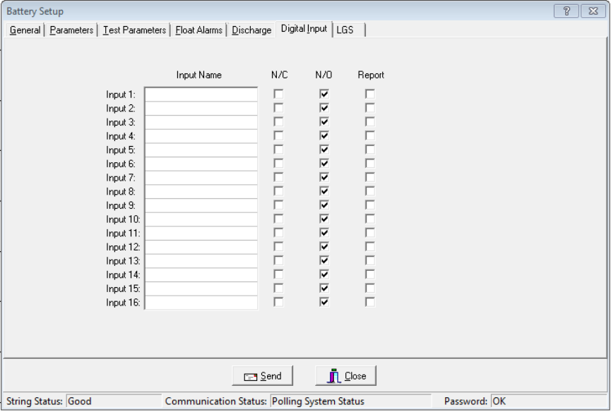
Programming Battery Setup for the MPM
17-11
17.6. Battery Setup: Digital Input (MPM)
String View > Setup|Battery|Digital Input
The MPM has 16 digital inputs that may be connected to external dry contacts. You may set
up these inputs on the Digital Input dialog box to report an alarm when the external contacts
are activated.
Figure 57. Battery Setup - Digital Input (MPM)
Input Name - Assign a name to the input connected to the external contacts and indicate if
the contacts are normally open or normally closed. To disable an input, clear the input name.
N/C or N/O - Select the N/C box if the external contacts are normally closed. Select the N/O
box if the external contacts are normally open.
Report - Selecting this check box lets the monitor report a digital input alarm. When not
selected, reporting is disabled for that input.
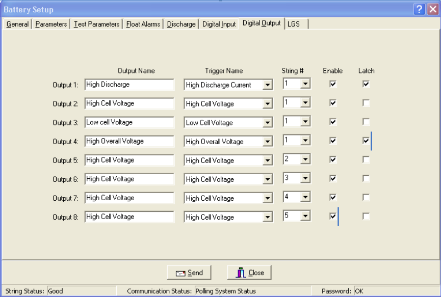
Programming Battery Setup for the MPM
17-12
17.7. Battery Setup: Digital Output (MPM)
String View > Setup|Battery|Digital Output
The MPM has three optional relay contact control outputs you can define to trigger on an
alarm event.
Figure 58. Battery Setup - Digital Output (MPM)
After defining an Output Name and Trigger Name, the associated digital output can change
state on an alarm to control a user-selected device. If you select Latch, the output latches. The
relay is a Form C contact that de-energizes upon alarm condition reset.
Output Name - Type a name that describes the external device being controlled.
Trigger Name - From the drop-down list, select a parameter that energizes the
Control Output relay contact.
Enable - Select Enable to energize a rear panel Control Output contact on a trigger event.
Latch - When selected, the Control Output contact energizes until manually reset. If not
selected, the Control Output de-energizes when the trigger event clears.
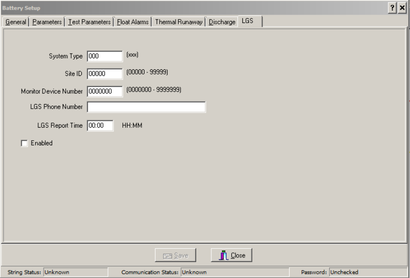
Programming Battery Setup for the MPM
17-13
Battery Setup: LGS (MPM)
String View > Setup|Battery|LGS
Leibert Global Services (LGS) offers a service in which its Customer Response Center (CRC)
remotely monitors your Alber BDS or MPM equipment and other facility devices around the
clock. The CRC evaluates alarms and provides immediate telephone and e-mail assistance
using a customer-defined response and escalation plan. For details about subscribing to the
service, phone (800) 748-3666 or (800) SITEMON or e-mail LGS.monitoring@Leibert.com.
If you have subscribed to an LGS monitoring plan, complete the Battery Setup|LGS dialog
box as follows.
Figure 59. Battery Setup - LGS (MPM)
System Type - Type three characters to identify the device being monitored.
For MPM-100, type MPM; for BDS-256, type 256; for BDS-40, type 040.
Site ID - Type the five character ID for customer site identification.
Monitor Device Number - Type the seven digit number used for customer device tracking.
LGS Phone Number - Type the telephone number that connects to the LGS remote
monitoring service. This number is used for a daily communication test and alarm reporting.
LGS Report Time - Type the time the monitor calls in each day to confirm communication.
Use the 24 hour clock; e.g., 13:45.
Enabled - Check this box to enable remote monitoring by LGS. Monitoring is enabled only
after a monitoring plan has been purchased from LGS.

Programming Battery Setup for the BDS
18-1
18. Programming Battery Setup for the BDS
From String Status, click Connection to display the String View screen.
String View > Setup|Battery|dialog box
After completing Preferences, Communication Setup, and System Setup, complete the Battery
Setup dialog boxes. To open Battery Setup, on the String Status screen, highlight the location
name, then click Connection. After computer to monitor communication is established, the String
View screen appears. To perform battery setup, select Setup|Battery to display the dialog boxes.
Password - If the Battery Setup boxes are protected, type the Battery Setup password and click
OK. This password closes when communication ends. If the password is incorrect, the
Battery Setup boxes appear, but the Send button is inactive.
To change the location, battery or string names after the monitor is set up and communicating,
use the Setup|System dialog boxes.
Send Button and Close Button - On the Battery Setup boxes, the Send button transfers settings
to the monitor. On Battery Setup|Test Parameters, the Historical Log, Resistance Test, and
Load Test settings are sent only if changed. You may complete all dialog boxes before clicking
Send. Clicking Send on any box transfers settings on all boxes. Changes are not saved or sent if
you only click Close.
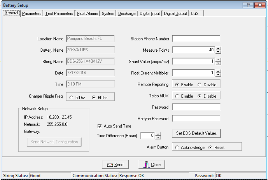
Programming Battery Setup for the BDS
18-2
18.1. Battery Setup: General (BDS)
String View > Setup|Battery|General
The following appear on the General dialog box.
Figure 60. Battery Setup - General (BDS)
Location Name, Battery Name, String Name - Location, battery, and string names identify
the strings and hardware to which the monitor is connected. Make sure databases have the
same names to ensure proper connection. Location, battery, and string names can only be
changed under Setup|System.
Date/Time - The date and time of the computer. When you send a new configuration to the
monitor, it sends this date and time.
Charger Ripple Freq - Select to set the system to the charger ripple frequency of
either 50Hz or 60Hz.
Station Phone Number - Type the telephone number of the Central computer the BDS
monitor calls when a system goes into alarm or discharge.
Measure Points - This is defined by Monitor Configuration on Setup|System|String.
Normally, do not change the Measure Points number; however, you may change it for custom
configurations not listed on System Setup|String. The Measure Points number defines the
total number of cells.
Shunt Value - Type the shunt rating in amps per millivolt. For example, for a shunt of
600 amps/100mV, type 6. (600 amps/100mv = 6 amps/1mv.) This value must be an integer.
Programming Battery Setup for the BDS
18-3
Float Current Multiplier - When a series of batteries is connected with more than one cable,
it may not be possible to get the float current sensor around all the cables. In this case, you
may connect the sensor around one of the cables and set the Float Current Multiplier for the
total number of cables. The connecting cables must be of equal length.
Remote Reporting Enable and Disable - Globally enables or disables the monitor remote
reporting function. For a parameter to report on alarm, do not select the global Disable Alarm
Reporting on Setup|Preferences, and select Remote Reporting on Setup|Battery|Float Alarms
or Setup|Battery|Discharge.
Telco MUX Enable and Disable - Select Enable when using a Telco multiplexer. This can
only be set when the BDS Controller is connected to String 1.
Password - To change the battery setup password, type the new password in the Password
and Re-type Password boxes. The password may be up to five alphanumeric characters long.
IP Address, Netmask and Gateway - Displays the IP address, netmask, and gateway typed
on Setup|System|Link.
Send Network Configuration - Click this button to send the IP address, netmask, and
gateway to the BDS. The BDS must have the internal network option installed. This button
transfers address only when BDSs are connected via RS-232 or modem, not network.
Set BDS Default Values - Click to transfer parameters for the Monitor Configuration
selected under System Setup|String to the Battery Setup|Parameters and
Battery Setup|Float Alarms dialog boxes and to the Measure Points field.
Auto Send Time - Check this box to have the time of day sent from the computer to the
hardware during autopolling and data extraction.
Time Difference (Hours) - This spin box lets you compensate for any plus or minus time
difference between the computer and hardware installation locations. When the computer
sends the time of day to the hardware, either during autopolling or Check Settings upload, the
time is automatically adjusted.
Alarm Button - If Sequential/Ack is selected on the System Setup Reporting dialog box,
select Acknowledge so the monitor notifies the computer that acknowledgement was sent
and received. This stops sequential calling but does not reset the alarm. Select Reset if
Sequential is not selected.
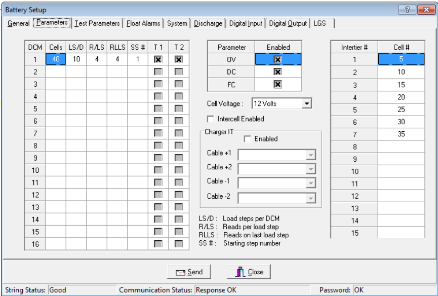
Programming Battery Setup for the BDS
18-4
18.2. Battery Setup: Parameters (BDS)
String View > Setup|Battery|Parameters
The following appear on the Parameters dialog box. For the BDS-40, the OV Enable,
Cell Voltage selection, and Intercell Enabled boxes are not available.
Figure 61. Battery Setup - Parameters (BDS-256)
DCM - For all DCM units 1 to 16 in use, configure these items according to the configuration
chart on the following pages.
Cells - Total number of cells monitored by the DCM.
LS/D - Load Steps per DCM.
R/LS - Reads per Load Step.
RLLS - Reads on Last Load Step.
SS# - Starting Step Number.
T1 and T2 columns - Temperature 1 and 2. Each DCM can monitor up to two
temperatures. No more than ten temperatures may be monitored for the entire string.

Programming Battery Setup for the BDS
18-5
Config
DCM
Cells
LS/D
R/LS
RLLS
SS#
1x198x1V
1
44
2
22
22
1
2
44
2
22
22
3
3
44
2
22
22
5
4
44
2
22
22
7
5
22
1
22
22
9
1x8x2V
1
8
-
-
-
-
1x31x2V
1
31
3
10
11
6
1x62x2V
1
30
2
15
15
5
2
32
2
15
17
7
1x65x2V
1
32
2
16
16
5
2
33
2
16
17
7
1x108x2V
1
36
2
18
18
1
2
36
2
18
18
3
3
36
2
18
18
5
1x122x2V
1
48
4
12
12
1
2
48
4
12
12
5
3
26
4
12
14
9
1x180x2V
1
46
2
23
23
1
2
46
2
23
23
3
3
46
2
23
23
5
4
42
2
23
19
7
1x182x2V
1
46
2
23
23
1
2
46
2
23
23
3
3
46
2
23
23
5
4
44
2
23
21
7
1x188x2V
1
48
2
24
24
1
2
48
2
24
24
3
3
48
2
24
24
5
4
44
2
24
20
7
1x192x2V
1
48
2
24
24
1
2
48
2
24
24
3
3
48
2
24
24
5
4
48
2
24
24
7
1x193x2V
1
44
2
22
22
1
2
44
2
22
22
3
3
44
2
22
22
5
4
44
2
22
22
7
5
17
1
17
17
9
1x203x2V
1
40
2
20
20
1
2
40
2
20
20
3
3
40
2
20
20
5
4
40
2
20
20
7
5
45
2
20
10
9
1x205x2V
1
40
2
20
20
1
2
40
2
20
20
3
3
40
2
20
20
5
4
40
2
20
20
7
5
45
2
20
25
9
1x210x2V
1
48
2
24
24
1
2
48
2
24
24
3
3
48
2
24
24
5
4
48
2
24
24
7
5
18
1
18
18
9
1x216x2V
1
48
2
24
24
1
2
48
2
24
24
3
3
48
2
24
24
5
4
48
2
24
24
7
5
24
1
24
24
9
1x232x2V
1
46
2
23
23
1
2
46
2
23
23
3
3
46
2
23
23
5
4
46
2
23
23
7
5
48
2
23
25
9
1x234x2V
1
48
2
24
24
1
2
48
2
24
24
3
3
48
2
24
24
5
4
48
2
24
24
7

Programming Battery Setup for the BDS
18-6
Config
DCM
Cells
LS/D
R/LS
RLLS
SS#
1x198x1V
1
44
2
22
22
1
2
44
2
22
22
3
3
44
2
22
22
5
4
44
2
22
22
7
5
22
1
22
22
9
5
42
2
24
18
9
1x238x2V
1
48
2
24
24
1
2
48
2
24
24
3
3
48
2
24
24
5
4
48
2
24
24
7
5
46
2
23
22
9
1x239x2V
1
48
2
24
24
1
2
48
2
24
24
3
3
48
2
24
24
5
4
48
2
24
24
7
5
47
2
24
23
9
1x240x2V
1
48
2
24
24
1
2
48
2
24
24
3
3
48
2
24
24
5
4
48
2
24
24
7
5
48
2
24
24
9
1x241x2V
1
48
2
24
24
1
2
48
2
24
24
3
3
48
2
24
24
5
4
48
2
24
24
7
5
24
1
24
24
9
6
25
1
25
25
10
Figure 62. BDS Configuration Data for Setup Files

Programming Battery Setup for the BDS
18-7
Config
DCM
Cells
LS/D
R/LS
RLLS
SS#
1x244x2V
1
48
2
24
24
1
2
48
2
24
24
3
3
48
2
24
24
5
4
48
2
24
24
7
5
24
1
24
24
9
6
28
1
28
28
10
1x246x2V
1
48
2
24
24
1
2
48
2
24
24
3
3
48
2
24
24
5
4
48
2
24
24
7
5
24
1
24
24
9
6
36
1
30
30
10
1x252x2V
1
48
2
24
24
1
2
48
2
24
24
3
3
48
2
24
24
5
4
48
2
24
24
7
5
24
1
24
24
9
6
36
1
36
36
10
1x6x4V
1
6
1
6
6
1
1x90x4V
1
45
5
9
9
1
2
45
5
9
9
6
1x120x4V
1
48
4
12
12
1
2
48
4
12
12
5
3
24
2
12
12
9
1x121x4V
1
48
4
12
12
1
2
48
4
12
12
5
3
25
2
12
13
9
1x122x4V
1
48
4
12
12
1
2
48
4
12
12
5
3
26
2
12
14
9
1x123x4V
1
48
4
12
12
1
2
48
4
12
12
5
3
27
2
12
15
9
1x60x6V
1
30
5
6
6
1
2
30
5
6
6
6
1x62x6V
1
30
5
6
6
1
2
32
5
6
8
6
1x65x6V
1
32
4
8
8
1
2
33
4
8
9
5
1x78x6V
1
40
5
8
8
1
2
38
5
8
6
6
1x80x6V
1
40
5
8
8
1
2
40
5
8
8
6
1x81x6V
1
40
5
8
8
1
2
41
5
8
9
6
1x60x8V
1
30
5
6
6
1
2
30
5
6
6
6
1x61x8V
1
30
5
6
6
1
2
31
5
6
7
6
1x30x12V
1
30
10
3
3
1
1x31x12V
1
31
10
3
4
1
1x32x12V
1
32
8
4
4
1
1x33x12V
1
33
10
3
6
1
1x36x12V
1
36
9
4
4
1
1x40x12V
1
40
10
4
4
1
Figure 63. BDS Configuration Data for Setup Files (continued)
Programming Battery Setup for the BDS
18-8
Parameter / Enabled - The OV, DC and FC parameters are assigned to DCM #1. Select
Enabled to view the parameter in String View and enable the hardware.
OV - Overall Volts. Not available for BDS-40.
DC - Discharge Current.
FC - Float Current.
Cell Voltage - From the drop-down list, select the nominal voltage of the cell or jar being
measured.
Intercell Enabled - Select this box if making separate measurements for intercells. Not
available for BDS-40.
Charger IT - Select the enabled check box if using the Charger IT option. This area allows
you to select and assign a cable to a DCM and intertier channel. The Cable+1 is the first
DCM and the Cable -1 is the last DCM.
Note: When intercells are enabled, they are defaulted to discrete. Each cable will have up to
four intertier channels, for example:
• <DCM 1> <IT 1>
• <DCM 1> <IT 2>
• <DCM 1> <IT 3>
• <DCM 1> <IT 4>
Note: On combined reading board, the intertier channel number will always start the first
available channel past the cells.
Intertier # / Cell # - For intertiers 1 to 15 in use, assign a cell number that relates to each
intertier.
Note: When cell 1 is most negative, when assigning an intertier to a cell, use the cell number
after the intertier.
The cell number is the lower of the two cell numbers across which the intertier is connected.
For example, typing 16 assigns the intertier between cells 16 and 17. Each DCM can monitor
up to ten intertiers. No more than 15 intertiers can be monitored for the entire string.
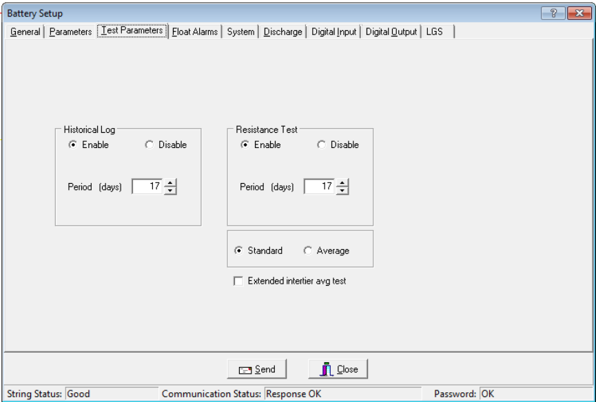
Programming Battery Setup for the BDS
18-9
18.3. Battery Setup: Test Parameters (BDS)
String View > Setup|Battery|Test Parameters
The following appear on the Test Parameters dialog box.
Figure 64. Battery Setup - Test Parameters (BDS)
Logging / R-Test Time Mode area - Click the Absolute Date and Time option button to
specify the exact day of the month, from 1 to 28 (29, 30 and 31 are not used), and time the
historical log is updated and the resistance test is performed. Click the Day Interval button to
specify how often (in days) the historical log is updated and the resistance test is performed.
Historical Log area - Click Enable to activate, then complete Period (days) and
Period (time) described below. Specify how often in days or the date and time the voltages,
currents, and temperatures are recorded in the history log.
Period (days) and Period (time) - Either select how often the historical log is updated, or
select the day of the month and time the log is updated.
Resistance Test area - Click Enable to activate, then complete Period (days) and
Period (time) described below. Specify the resistance test interval in days or date and time. If
set to 30 days, resistance is tested every 30 days starting at 12:00 A.M. (midnight). When the
monitor performs a resistance test, it creates a historical log entry. For this reason, you may
want to select a resistance test 14 days away from a historical log entry.
Period (days) and Period (time) - Either select how often the resistance test is performed, or
select the day of the month and time the test is performed.
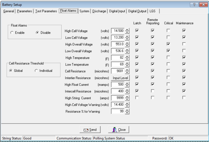
Programming Battery Setup for the BDS
18-10
Standard or Average - Normally select Standard. If the charger employs digital control of
battery voltage, which causes voltage fluctuation, select Average.
Extended Intertier Avg Test - If this box is checked, when a resistance test is performed,
the intertier resistance is sampled a greater number of times and the result is averaged. This
feature is useful when testing in high noise environments.
Average Cell Resistance - This field displays the average value of the last resistance test run.
Resistance offset adjustment +/- This field allows you to adjust your resistance
measurements by percentage with a plus or minus offset adjustment. This function only
applies to future resistance tests that are rerun. You may enable or disable this function at
anytime during the process by clicking on the Enabled checkbox.
18.4. Battery Setup: Float Alarms (BDS)
String View > Setup|Battery|Float Alarms
The following appear on the Float Alarms dialog box.
Figure 65. Battery Setup - Float Alarms (BDS)
Float Alarms Enable or Disable - Global control of all float alarms for local alarm status
and alarm contact activation. Select Enable for the call-out of float alarms and digital input
alarms. When Disable is selected, the String Status column on the String Status screen
indicates Alarms Disabled.
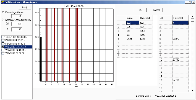
Programming Battery Setup for the BDS
18-11
Cell Resistance Threshold - Global applies the alarm level in the Cell Resistance
(microhms) field to all cells. Individual and Input Level sets alarm levels on a cell basis
using the Cell Resistance Alarm Levels box.
Figure 66. Cell Resistance Alarm Levels Setup (BDS)
Cell Resistance Alarm Levels box - To set Alarm Levels on a cell basis, click Individual and
Input Level and select options on this box.
Percentage Above - Sets the cell alarm level a percentage above the selected dataset
levels. Type a value (1 to 99) in the Percentage Above field.
Absolute Above (Microhms) - Sets the cell alarm level a numeric value above the
selected dataset levels. Type a value in microhms in the Absolute Above field.
Date area check boxes - Click one dataset date in this area on which to base alarm
levels. The system stores the date of the baseline data and displays it on the lower right
after the Apply button is clicked.
Apply - Click apply to apply selected levels to the cells. The values appear in the
Threshold column. If you do not want to edit individual cell levels (see below), click OK.
Cell, Intertier and Threshold columns - To edit individual cell or intertier alarm levels
in the Threshold column, click the value and type a new value. After editing, click OK.
Note: Values are not saved until Save or Send is clicked on the Float Alarms or another
Battery Setup box.
Alarm Thresholds - For high and low cell voltage, overall voltage, temperature, and
resistance, select violation threshold values that activate an alarm during a float condition.
These thresholds are deactivated for 30 minutes following a resistance test. If a discharge
occurs, the alarms are disabled until the overall voltage recovers to a value above the low
threshold.
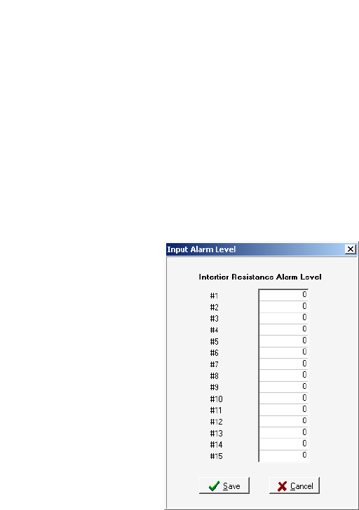
Programming Battery Setup for the BDS
18-12
High Cell Voltage Warning (volts) - Type a value between the Low Cell Voltage and High
Cell Voltage levels. This setting affects the bar graph colors on the Cell Voltage String View
screen. During normal float condition, the bar colors change as follows:
High Violation ................... Red
Warning ............................ Blue
Normal .............................. Green
Low Violation .................... Yellow
Out of Range Values ........ Maroon
Negative Cell Voltage ....... Black
String View > Setup|Battery|Float Alarms|Input Level then Save or Cancel
Intertier Resistance Input Level - Click Input Level to display the Input Alarm Level box.
Type the resistance alarm level threshold (in microhms) for each intertier. The cell numbers
in this box are the lower of the two cell numbers across which the intertier is connected.
(These cell numbers are selected under Battery Setup|Parameters.)
Note: The charger cable is only used for BDS and is intended to only be used for individual
thresholds.
Figure 67. Input Alarm Level
(Intertier Resistance Alarm Level)
Percentage for Warning - Determines the violation threshold that causes a Warning battery
status. The value entered is a percentage of the internal resistance alarm. For example, if the
internal resistance alarm is set to 100 microhms and the percentage for warning is 75%, the
system issues a warning when the internal resistance is between 75 and 100 microhms. When
the value exceeds 100 microhms, the system issues an alarm. Warning status is displayed
only on the String Status and Historical Events screens, not on the Alarms screen.
<-----Normal-----75%<-----Warning----->100%-----Alarm----->
Latch - When selected, the alarm contact stays energized until manually reset. If not selected,
the alarm contact de-energizes when the alarm condition clears.
Bar Colors for all
Normal and
Violation Types
Programming Battery Setup for the BDS
18-13
Remote Reporting - When selected, causes the monitor to report the alarm. When not
selected, reporting is disabled for that parameter. You must select this option and Remote
Reporting Enable under Setup|Battery|General to enable the call out function and to display
Alarm Detail on the Historical Events screen during polling.
Critical and Maintenance - Two alarm contacts are available. Select Critical or Maintenance
to define which contacts energize upon alarm. If neither is selected, the Remote Reporting
check box clears and alarm reporting is disabled for that parameter. These settings do not
affect bar graph colors.
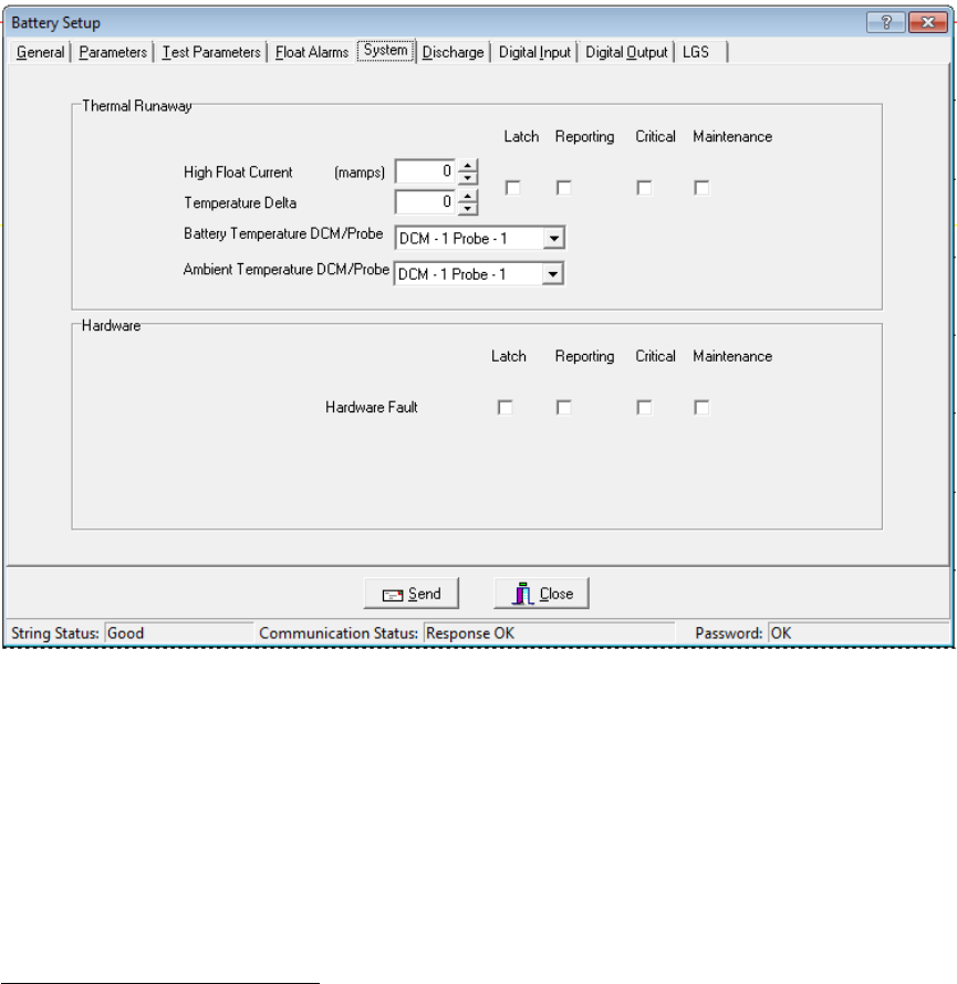
Programming Battery Setup for the BDS
18-14
18.5. Battery Setup: System (BDS)
String View > Setup|Battery|System
The Thermal Runaway and Hardware parameters are used to trigger system events.
Thermal runaway can be a very destructive and serious condition on standby batteries if not
identified in the beginning of the development stages. If thermal runaway is ignored, severe
damage to the battery as well as surrounding equipment can occur resulting in costly repairs
or worse, injury to personnel. In all cases, thermal runaway can lead to abrupt system failure
and disruption of service if not detected. A proactive method of some form must be instituted
to deal with a thermal runaway condition. Furthermore, as described in the International Fire
Code (IFC), VRLA battery systems shall be provided with a listed device or other approved
method to preclude, detect and control thermal runaway (IFC 608.3)1.
Figure 68. Battery Setup - Thermal Runaway (BDS)
High Float Current (in mamps) A float current threshold, which is independent of the Float
Alarms - Float Current threshold, can be set. Entering a value of 0 will disable this parameter
from the analysis for thermal runaway. Otherwise, a value from 1-5000ma can be entered.
Seeing an abnormal rise in float current can be an indication of a thermal runaway condition.
However, normal conditions like charging after a discharge can and will show elevated float
currents for a period of time. The length of time and the amount of this elevated float current
is difficult to predict as the depth of discharge and type of battery will affect this. Due to this,
this parameter will be temporary disabled for making thermal analysis for 72 hours following
a discharge.
1 ICC, 2012 ICC International Fire Code® (IFC)
Programming Battery Setup for the BDS
18-15
Temperature Delta A temperature delta can be set to identify the difference in temperature
between two temperature probes. The desired location of these probes would be one
measuring ambient temperature in the vicinity of the battery and the other placed directly
onto the battery. Entering a 0 will disable this parameter for the analysis for thermal runaway.
Otherwise, a value from 1-99F or 1-38C can be entered.
Note: To apply the Thermal Runaway feature, you must select a High Float Current
mamps value and/or a Temperature Delta value. If both methods are used then both
conditions must be met.
Although only one parameter can be used, it is advised to use both as the float current can be
automatically disabled for a period of time following a discharge event. In the event a thermal
runaway condition occurs during the recharge following a discharge, the temperature delta
will rise indicating a thermal runaway condition. The BDS will now log high float current
and/or temperature.
Latch - When selected, the high float current and temperature Delta alarm stays on until
manually reset. If not selected, the alarm will go off when the high float current or
temperature condition clears.
Reporting - When selected, the alarm will be reported and an alert will be displayed in the
system. If not selected, the alarm will not be reported when a high float current or
temperature alarm occurs on the system.
Critical Alarm and Maintenance Alarm - Two alarm are available for thermal runaway.
Select Critical or Maintenance Alarm to define which alarm will report and appear in the
system. If neither alarms are selected, alarm reporting is disabled for discharge.
Battery Temperature and Ambient Temperature DCM/Probe – These are selections to
define where the probes are physically attached to the monitoring hardware. The system will
know what DCM’s are available but the individual setting the system up will need to know
which probes to use and therefore properly assign them.
There is only one set of Latch/Reporting/Critical/Maintenance settings because either
parameter will cause a thermal runaway event to be created in the alarm logging.
Optional Relay Module - If the system is configured with the optional relay module, each
contact can be configured to a thermal runaway event as shown below. Each contact can be
defined to a particular string and programmable to be latching or non-latching. If the alarm
module is used for the BDS-40, there are only six alarm contacts available. If it is a BDS-256,
then there are eight contacts available.
The Hardware section allows you to configure and generate alarms on hardware faults. At
the time of this BMDM software release, the only hardware fault monitored is a
communication fault between the BDS Controller and DCM’s.
It is required to have Latching enabled. Critical and Maintenance should only be checked if
the indicators on the front panel and alarm relay operation are required. Remote reporting is
not required for this alarm to function properly.
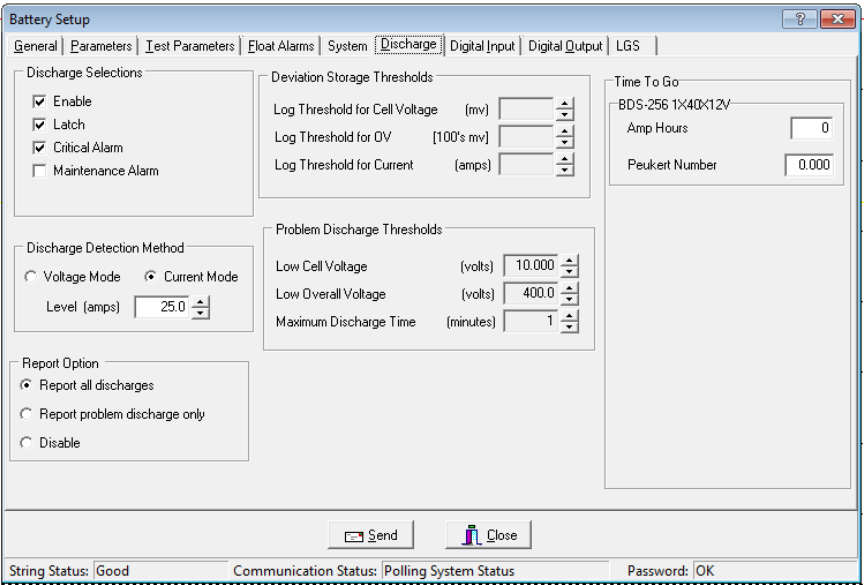
Programming Battery Setup for the BDS
18-16
18.6. Battery Setup: Discharge (BDS)
String View > Setup|Battery|Discharge
The following appear on the Discharge dialog box.
Figure 69. Battery Setup - Discharge (BDS)
Discharge Selections Area:
Enable - Select to let the monitor capture and store discharge data. If not selected, the
BDS does not log discharges.
Latch - When selected, the alarm contact stays energized until manually reset. If not
selected, the alarm contact de-energizes when the discharge condition clears.
Critical Alarm and Maintenance Alarm - Two alarm contacts are available. Select
Critical Alarm or Maintenance Alarm to define which contacts energize upon alarm. If
neither is selected, alarm reporting is disabled for discharge. These settings do not affect
bar graph colors.
Discharge Detection Method Area:
Select Voltage Mode or Current Mode, then set the threshold Level in volts or amps to
activate data logging during a discharge. When the voltage goes below the set level or the
current exceeds the set level, the monitor begins recording cell voltages, discharge
current, and overall voltage, based on the Deviation Storage Thresholds (described later).
Only one temperature sample is stored at the beginning of the discharge.
Programming Battery Setup for the BDS
18-17
Note: If using the Current Mode, the minimum threshold Level to detect discharges must
be at least 5% of the current transducer (CT) rating. For example, if the CT rating
is 600A, the minimum Level is 30A.
Voltage mode allows data recording during recharge, since data logging does not stop
until the voltage goes above the threshold. If measuring discharge current, use
Discharge Current Mode as a reliable source of trigger.
To enable current mode, you must define the Current Channel on Setup|Battery|
Parameters in the DCM# column.
Report All Discharges - If selected, the monitor reports all discharges to the Central
computer. You must enable Remote Reporting on Setup|Battery|General.
Report Problem Discharge Only - If selected, the monitor reports only discharges that
exceed voltage or time values set in Problem Discharge Thresholds (described later) to the
Central computer.
Disable - If selected, stops the BDS from reporting a discharge.
Deviation Storage Thresholds Area - This feature does not apply to the BDS.
Problem Discharge Thresholds Area:
Low Cell Voltage, Low Overall Voltage, and Maximum Discharge Time - Select the
voltage or time levels that trigger discharge reporting. To enable these values, select
Report Problem Discharge Only on this screen. This setting also affects the bar graph
colors on the Cell Voltage String View screen. During a discharge, the bars change color:
Normal Condition .......................................................................... Green
Problem Discharge Thresholds or Low Cell Voltage .................... Yellow
Time to Go Area:
The String View screen can display a Time to Go (TTG) number. When a BDS discharge
starts, the TTG box on String View indicates the estimated remaining time that the
battery can deliver power. To disable this feature, leave the Amp Hours and Peukert
Number boxes at zero.
IMPORTANT NOTE: The TTG Time to Go number is only an estimate.
Amp Hours - Type the amp hours of the battery at the 8 hour rating. To disable the
estimated time feature, set to 0.
Peukert Number - Type the Peukert number derived by using Peukert's equation. Refer
to Understanding the Time to Go Algorithm. To disable the estimated time feature, set
to 0.
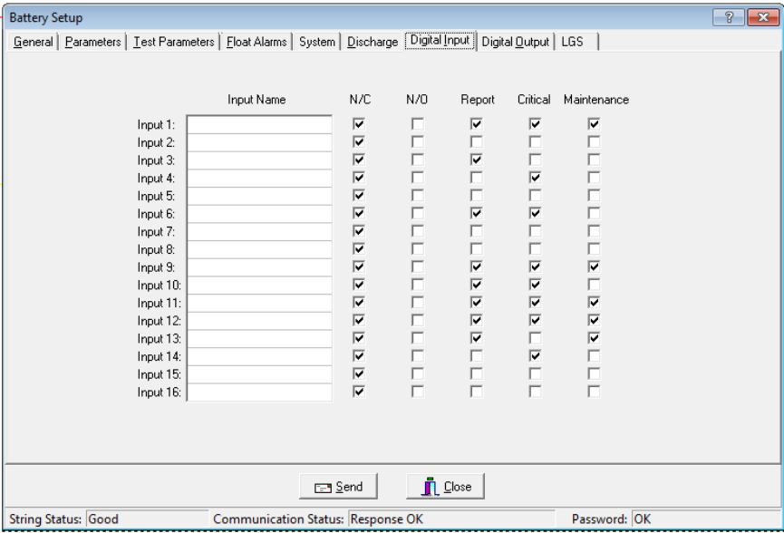
Programming Battery Setup for the BDS
18-18
18.7. Battery Setup: Digital Input (BDS)
String View > Setup|Battery|Digital Input
The Digital Input dialog box is available only when connected to String 1 of the BDS-256
controller, as defined on Setup|System|String. The BDS has 16 digital inputs that may be
connected to external dry contacts. You may set up these inputs to report an alarm when the
external contacts are activated. An alarm can also activate the critical or maintenance relay on
the BDS. Not available for BDS-40.
Figure 70. Battery Setup - Digital Input (BDS-256)
Input Name - Assign a name to the input connected to the external contacts and indicate if
the contacts are normally open or normally closed. To disable an input, clear the input name.
N/C or N/O - Select the N/C box if the external contacts are normally closed. Select the N/O
box if the external contacts are normally open.
Report - Selecting this check box lets the monitor report a digital input alarm. When not
selected, reporting is disabled for that input.
Critical and Maintenance - Two alarm contacts are available. Select Critical or Maintenance
to define which contacts energize upon digital input alarm. If neither is selected, the Report
check box clears and alarm reporting is disabled for that input. These settings do not affect
the bar graph colors.
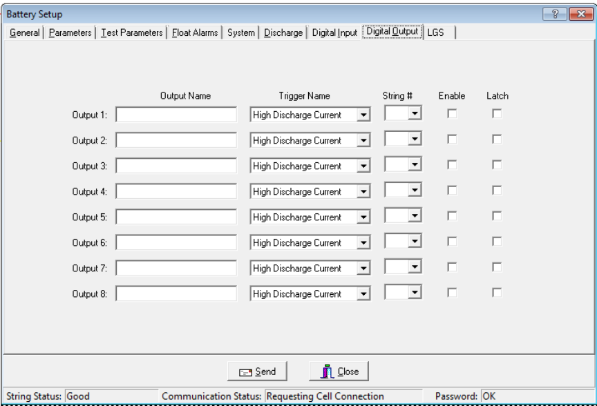
Programming Battery Setup for the BDS
18-19
18.8. Battery Setup: Digital Output (BDS)
String View > Setup|Battery|Digital Output
The Digital Output dialog box is available only when connected to String 1 of the BDS
controller, as defined on Setup|System|String. Not available for BDS-40.
Note: Hardware failure – Latching should be enabled when using this trigger.
Figure 71. Battery Setup - Digital Output (BDS-256)
The BDS has eight optional relay contact control outputs you can define to trigger on an
alarm event. After defining an Output Name and Trigger Name, the associated digital output
can change state on an alarm to control a user-selected device. If you select Latch, the output
latches. The relay is a Form C contact that de-energizes upon alarm condition reset.
Output Name - Type a name that describes the external device being controlled.
Trigger Name - From the drop-down list, select a parameter that energizes the
Control Output relay contact.
String # - The BDS Controller can have up to eight strings. In the String # box, select All or
the number that corresponds to the string number on System Setup|String.
Enable - Select Enable to energize a rear panel Control Output contact on a trigger event.
Latch - When selected, the Control Output contact energizes until manually reset. If not
selected, the Control Output de-energizes when the trigger event clears.
Note: For BDS setup, the system shows information based on string one only. If you have
more than one, they are defaulted from string one.
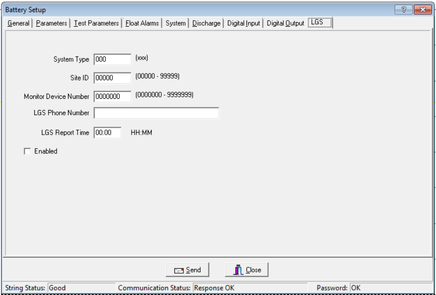
Programming Battery Setup for the BDS
18-20
18.9. Battery Setup: LGS (BDS)
String View > Setup|Battery|LGS
Leibert Global Services (LGS) offers a service in which its Customer Response Center (CRC)
remotely monitors your Alber BDS or MPM equipment and other facility devices around the
clock. The CRC evaluates alarms and provides immediate telephone and e-mail assistance
using a customer-defined response and escalation plan. For details about subscribing to the
service, phone (800) 748-3666 or (800) SITEMON or e-mail LGS.monitoring@Leibert.com.
If you have subscribed to an LGS monitoring plan, complete the Battery Setup|LGS dialog
box as follows.
Figure 72. Battery Setup - LGS (BDS)
System Type - Type three characters to identify the device being monitored.
For MPM-100, type MPM; for BDS-256, type 256; for BDS-40, type 040.
Site ID - Type the five character ID for customer site identification.
Monitor Device Number - Type the seven digit number used for customer device tracking.
LGS Phone Number - Type the telephone number that connects to the LGS remote
monitoring service. This number is used for a daily communication test and alarm reporting.
LGS Report Time - Type the time the monitor calls in each day to confirm communication.
Use the 24 hour clock; e.g., 13:45.
Enabled - Check this box to enable remote monitoring by LGS. Monitoring is enabled only
after a monitoring plan has been purchased from LGS.
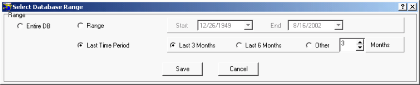
Selecting the Database Range
19-1
19. Selecting the Database Range
String Status > Setup|Database Range
To select a database range before connecting to a location, select Setup|Database Range. The
Select Database Range dialog box appears.
Figure 73. Select Database Range
Entire DB - Select to view all available data in the string database.
Range - To view data within a range of dates, click Range then select Start and End dates. To
choose a date, click the date box drop-down button and click the calendar. To change months,
click the left or right arrows on the calendar or press the Page Up / Page Down keys. To change
years, hold the Ctrl key while pressing Page Up or Page Down.
Last Time Period - To select three or six months back from today's date, click Last Time Period
then select Last 3 Months or Last 6 Months. Select Other for other month periods and choose a
value. Close the dialog box to save the selections.
IMPORTANT NOTE: If no data appears on String View, select Entire DB to determine if data is
available.
Save - Clicking Save saves the selected range for all databases, not just the database currently
open. To close the dialog box without making any changes, click Cancel.

Connecting to a Battery Location
20-1
20. Connecting to a Battery Location
This section describes how to connect the BMDM program to a location. At this point, the
computer and monitor should have been synchronized using Check Settings. You may connect to
an MPM or BDS battery location site via modem or network from a remote location or on-site
using the network or RS-232 Local port. These connection methods check all battery parameters.
If you cannot connect to a location, refer to Synchronizing Using Check Settings. If using a
Service computer, refer to the Service computer notes in the same section.
20.1. Connecting via Modem
Connection
Confirm Setup|System|Link is set for a modem connection. On the String Status screen, click
the string to which you want to connect, then click Connection to call the number specified
under Setup|System|Link. Upon connection, String View displays all real time data. If no data
appears, check the Setup|Database Range setting.
20.2. Modem Hang Up
Connection then Hang up
When connecting via modem, sometimes you may want to disconnect before the BMDM
connects to the string. To stop modem dial out after clicking Connection, click the Hang Up
button on String Status or select Setup|Hang Up.
NOTE: If the BMDM connects and String View appears, closing the String View screen
disconnects the modem.
20.3. Connecting via Network
Connection
Confirm Setup|System|Link is set for a network connection. On String Status, click the string
to which you want to connect, then click Connection to connect to the IP address specified
under Setup|System|Link. Upon connection, String View displays all real time data. If no data
appears, check the Setup|Database Range setting.
20.4. Connecting via RS-232 Local Port
Connection
Confirm Setup|System|Link is set for a direct connection. On String Status, click the string to
which you want to connect, then click Connection. If the site has been set up, String View
displays all real time data. If the site was not set up, set up the new system.

Viewing Battery and Monitor Status
21-1
21. Viewing Battery and Monitor Status
At program start, the String Status screen lists all available monitor systems. The program can sound an
alarm, contact a pager, send a fax or email, or print alarm event details. When a monitor reports an alarm,
an alarm detail box appears until you acknowledge it. The String Status column on the String Status
screen lists the condition, and Update Date indicates alarm time. Historical Events displays the history
and details about the alarm. When there is a new entry, click the flashing Historical Events button to
display the history. This chapter describes these screens.
F3 - Press the F3 key to toggle between the string, battery, location, and customer status screens.
There are two ways to view data from a battery: real-time and offline.
Viewing battery data in real time means having the computer connected to the monitor via modem,
LAN, or an RS-232 cable. After communication is established, String View displays the real time
readings.
Viewing data offline means viewing data removed from the monitor and stored in the computer database.
To view data offline, highlight the site on String Status, then select View|Offline. String View displays
data for the site. No voltages are displayed because the system is offline and not connected to the site.
IMPORTANT NOTE: If no bar graph data appears on String View, go to the menu bar on String Status,
click Setup|Database Range, then select Entire DB to determine if data is available.
21.1. Opening and Saving a Database
String Status > Open or File|Open
At start up, the BMDM opens the previously opened database. To open another database, select Open,
highlight the desired database, and click Open. You do not need to close the currently open database
before opening a new one.
String Status > File|Open Backup
The Open Backup selection works the same as Open. When the program opens an Access backup file,
it converts it from a ZIP to an MDB file.
String Status > File|Save As
String Status > Backup database or File|Backup Database
To save an Access database as an MDB database file, select File|Save As. To save the database as a
backup, select File|Backup Database, which saves the MDB file as a ZIP file. Refer to Understanding
Polling, Extraction and Backup.
String Status > Close or File|Close
String Status > File|New
To close a database, select File|Close. To create a new database, select File|New.
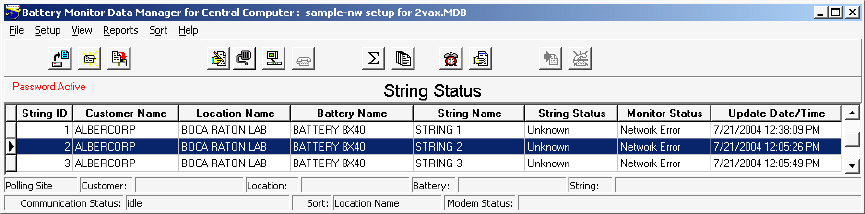
Viewing Battery and Monitor Status
21-2
21.2. String Status Screen
At start-up, the BMDM displays the String Status screen. The first time the program runs, no strings
are listed. The communication and status fields summarize the polling status, string and location
names, connection status, and errors.
Figure 74. String Status
String Status has up to eight columns that indicate the status of each string: String ID, Customer
Name, Location Name, Battery Name, String Name, String Status, Monitor Status, and Update
Date/Time. The columns are updated every time the monitor reports status, you manually call a
location, or during polling. You can hide the String ID, Customer Name, Location Name, and Battery
Name columns using Setup|Preferences.
String ID - The string ID is needed only if using a pager. When a page is issued, the numeric
message includes the string ID, which indicates the string in alarm condition.
String Status - The String Status column reports six conditions on the Historical Events screen, no
priority assigned, and eleven on the String Status screen, each assigned a priority. For example, if
conditions Alarm and Warning exist, when the monitor calls, it reports Alarm because Alarm has
higher priority than Warning. However, Warning is not lost. When you acknowledge and reset Alarm,
the Warning status appears on disconnect.
Priority Status Meaning
1 Acknowledge When acknowledge function is enabled, indicates an event has occurred
that must be acknowledged, either through the program or by pressing
the reset button.
2 Names do not match Location, battery or strings names do not match between the hardware
and database.
3 Names need to be set up Location, battery or strings names are not programmed into the
hardware.
4* DCM Com Error Communication error between DCM and BDS Controller.
5 Discharging The battery is in discharge.
6* Unknown The system has not yet been called. (New string entry.)
7* Discharge Occurred Battery discharge occurred.
8* Alarm A battery parameter violated an alarm threshold.
9* Warning A resistance reading violated a warning threshold.
10* Alarm Disabled Alarm Disabled in Battery Setup.
11 Good System within normal parameters.
* also appears on Historical Events screen.
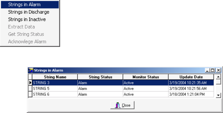
Viewing Battery and Monitor Status
21-3
Monitor Status - The Monitor Status column can report ten conditions, which do not have priority
ratings assigned.
Status Meaning
Invalid Data Data received from the monitor was corrupted.
Check Hardware Monitor reported a hardware failure. Items checked are described
in Diagnostics - Self Test.
Network Error Cannot connect or cannot initialize.
No Dial Tone No dial tone detected when calling.
Monitor Busy Busy signal detected when calling.
Modem Error Modem cannot be initialized.
Inactive Monitor did not answer. This could be hiding a problem. With no response, assumes the
monitor is inoperative. For no dial tone or a busy line, attempts to poll a second time.
Active Monitor answered. No problems reported.
Data Corrupt After connecting to the monitor, you must click Clear Data Memory
on Diagnostics|Memory.
Comm Error During autopolling, if computer cannot establish communication after three tries, this
message appears.
Line Busy The phone number the modem dialed is busy.
No Answer The phone number the modem dialed did not respond.
All conditions except Active produce an Unknown in the String Status column.
Update Date/Time - The date and time the status was delivered.
String Status > Sort|column name
The String Status screen sorts on String ID. To sort on a different column, select Sort then the column
name, or click a column header. To move columns, click and drag a column header onto another
column header.
String Status > Right click a string name
or String Status > View|String in Alarm or String in Discharge or String in Inactive
Figure 75. String Status Viewing Selection
Figure 76. Strings in Alarm
Right click on a string name on the String Status screen to
display a pop-up menu. Click Strings in Alarm, Strings in
Discharge or Strings in Inactive to display a list of the selected
category. The Strings in Alarm screen is shown below. The
Strings in Inactive and Strings in Discharge screens are similar.
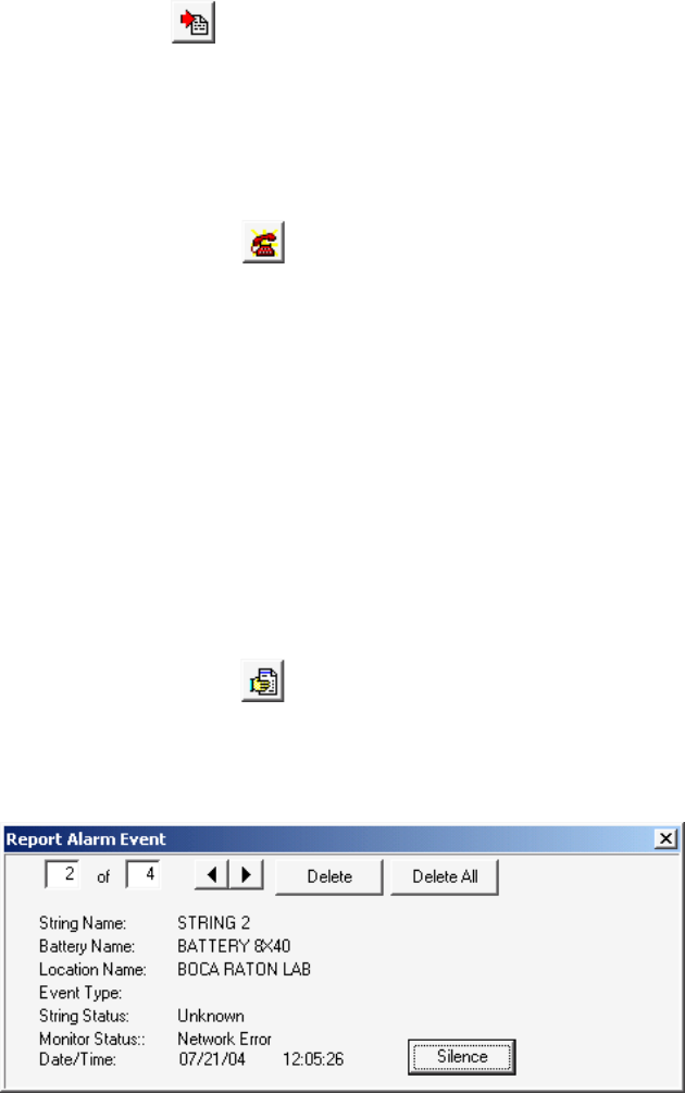
Viewing Battery and Monitor Status
21-4
String Status > Extract all data or String Status > Right click a string name | Extract data
The Extract All Data button and the Extract Data item on the pop-up menu are enabled if
Auto Extract Data is selected and Disable Auto Polling / Auto Answering is not selected on
Setup|Communication. The Extract All Data button polls all strings listed on the screen. Extract Data
polls only the string highlighted. In both cases, the BMDM gets the string status and alarm events and
extracts the voltage float data, resistance data, and discharge data.
String Status > Call all modem strings or
String Status > Right click a string name | Get String Status
The Call All Modem Strings button and the Get String Status item on the pop-up menu are enabled
if any string is connected via modem and Auto Extract Data is selected and
Disable Auto Polling / Auto Answering is not selected on Setup|Communication. The
Call All Modem Strings button polls all strings listed on the screen. Get String Status polls only the
string highlighted. In both cases, the BMDM gets the present string status and alarm events, but does
not extract data.
String Status > Right click a string name | Acknowledge alarm
You may acknowledge alarms three ways. One way is to right click the mouse on the String Status
screen and click Acknowledge Alarm on the pop-up menu. Refer to Alarm Acknowledge for details.
21.3. Report Alarm Event Screens
String Status > Show all alarm events
There are four dialog boxes that appear on String Status when an alarm event occurs: Report Alarm
Event, Print Report Alarm Event, Fax Report Alarm Event, and Page Report Alarm Event. If there is
an alarm condition, the Report Alarm Event box appears during polling.
Figure 77. Report Alarm Event
The Print, Fax and Page Report Alarm Event boxes appear only if Print Alarm Event, Fax Alarm
Event or Page On Alarm are checked on Setup|System|Reporting and Disable Alarm Reporting on
Setup|Preferences is not checked. To stop the audible alarm if enabled, click Silence. Click Delete to
remove the currently displayed alarm. Delete All removes all displayed alarms. The print, fax, and
page event boxes close after the printer, fax machine or pager receives the alarm.
Clicking Show All Alarm Events displays the Report Alarm Event dialog box. You may view all
events by clicking the left or right arrows on the box.
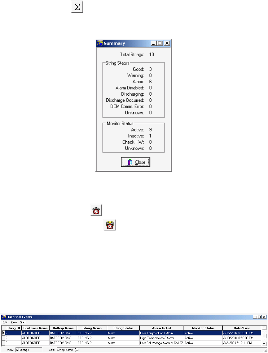
Viewing Battery and Monitor Status
21-5
21.4. Summary Screen
String Status > Summary or View|Summary
The Summary dialog box displays a status summary of the battery sites. Click the Summary button to
display this box.
Figure 78. Summary (Battery Sites)
21.5. Historical Events Screen
String Status > Historical events or View|Historical Events
Note: View Alarm has a ringing clock
When a new event is added, the Historical Events button flashes. Select Historical Events to display
the Historical Events screen, which lists reported events and the history of one or all strings. You may
click the column header to sort on the column. To move columns, click and drag a column header
onto another header.
String Status > View|Historical Events|View|Single String
To view a single string, select Single String on the Historical Events screen. On the Input Dialog box,
choose a string name from the drop-down list, then click OK. The screen displays all the historical
events for the selected string.
Figure 79. Historical Events

Viewing Battery and Monitor Status
21-6
Alarm Detail - A computer polling or receiving an alarm call from a monitor receives and displays
this information if:
Remote Reporting options are enabled under Setup|Battery|Float Alarms,
Remote Reporting is enabled on Setup|Battery|General,
Report Option is not disabled on Setup|Battery|Discharge, and
Disable Alarm Reporting is not checked on Setup|Preferences.
The Alarm Detail column can report the following conditions, which do not have priority ratings
assigned.
High Cell Voltage at String n, Cell n High Intertier Resistance n
Low Cell Voltage at String n, Cell n Discharge
High Resistance at String n, Cell n Digital Input n
High Intercell Resistance at String n, Cell n UPS Low Voltage
High Overall Voltage UPS Line Fail
Low Overall Voltage Pager Busy
High Float Current Pager Error
Warning at String n, Cell n Pager Fail
High Temperature n Unknown
Low Temperature n Inactive
21.6. String View Screens
From String Status, click Connection to display the String View screen.
String View > Cell voltage or Cell resistance or Intercell resistance
From the String Status screen, highlight the location name, then click Connection. After
communication is established, the String View screen appears. The title bar displays S, B and L for
string, battery, and location names. This chapter describes features common among the Cell Voltage,
Cell Resistance, and Intercell Resistance screens, which are accessed by clicking the tabs. The
Intercell Resistance tab appears for a BDS only after you request a resistance test.
To open a different string, choose a string name on the drop-down list or click the arrows on String
View. Only MPM and BDS strings with the same phone number appear in the list. MPM strings with
a MUX setting of zero do not appear.
String View > View|Undo Zoom
To view the level of an individual cell, refer to Cell Voltage Box. To perform a trend analysis, refer to
Trend Analysis. To zoom in on the bar graph, place the cursor over the bars and drag a rectangle over
the area of interest while holding the left mouse button. To restore to original size, click Undo Zoom.
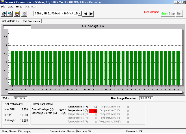
Viewing Battery and Monitor Status
21-7
21.7. Cell Voltage (String View Screen)
String View > Cell voltage (default)
The String View Cell Voltage screen bar graph shows the voltage of each cell or module within the
battery. A readings summary appears at the bottom. The cells with the maximum and minimum
values are indicated as Max(n) and Min(n). If current channel and temperature transducers are
installed, these readings also appear. If you click a bar on the graph, the cell voltage value appears in
the box near the top left.
Figure 80. String View - Cell Voltages (MPM shown)
Clicking certain text in the lower portion of the String View screen displays screens related to the
item clicked. For example, clicking Other Parameters - Overall Voltage displays the Overall Voltage
Trend screen.
If the Peukert number is enabled for the MPM under Battery|Setup|Discharge, the screen displays
the TTG (Time to Go) and Discharge Duration boxes. During discharge, TTG gives an estimate of
the discharge time remaining, based on user-entered data. Discharge Duration indicates the time that
has elapsed since the start of the discharge.
IMPORTANT NOTE: The TTG Time to Go is only an estimate.
When in discharge mode, if a cell goes negative, the respective bar on the bar graph is displayed in
black.
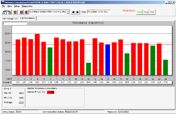
Viewing Battery and Monitor Status
21-8
The String Status box on the bottom left of the String View screen can report nine conditions.
Priority Status Meaning
1 DCM Com Error Communication error between DCM and BDS Controller.
2 Discharging The battery entered a discharge.
3 R-Test in Progress Resistance test in progress.
4 Calibration in Progress
5 Check Hardware Monitor reported a hardware failure. The items checked are
described in Diagnostics – Self Test.
6 Discharge Occurred
7 Alarm A battery parameter violated an alarm threshold.
8 Warning A resistance reading violated a warning threshold.
9 Good System is within normal parameters.
21.8. Cell Resistance and Intercell Resistance (String View Screens)
String View > Cell resistance or Intercell resistance
You may automatically read internal cell resistance and intercell resistance by setting a timer under
Setup|Battery|Test Parameters, or you may start the test from the Cell Resistance screen. The BMDM
reads cell and intercell resistance at the same time. The Intercell Resistance tab (BDS only) appears
after the BMDM performs a resistance test. An intercell reading option is required in the BDS.
The Cell Resistance and Intercell Resistance screens display bar graphs. Click the Cell Resistance tab
to transfer resistance readings from monitor to computer. It may take a few seconds for the bar graph
to appear. If readings are available, the BMDM displays the latest set and saves them to the database
with the date and time taken.
Figure 81. String View - Cell Resistance (MPM shown)
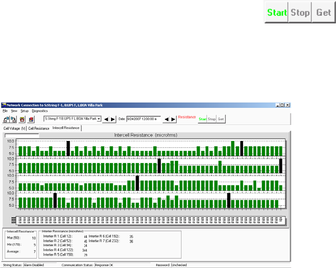
Viewing Battery and Monitor Status
21-9
String View > Start resistance test or Stop resistance test or Get test results
To start a resistance test and capture new readings, click Start. After the Test in Progress message
disappears, the monitor Resistance Test LED goes out and the Get button becomes active. Click Get
to display the readings and transfer them to the computer. The bottom of the screen summarizes
resistance and intertier values. Intertier cells are indicated in black. To stop the test before
completion, click Stop.
Figure 82. String View - Intercell Resistances (BDS only)
To view the Intercell Resistance bar graph, click the Intercell Resistance tab.
Clicking Start when using a BDS selects all DCM's for testing. For troubleshooting, you may select
Diagnostics|R-Test in a DCM and choose which DCM's to resistance test. Refer to Resistance Testing
Multiple DCM Units.
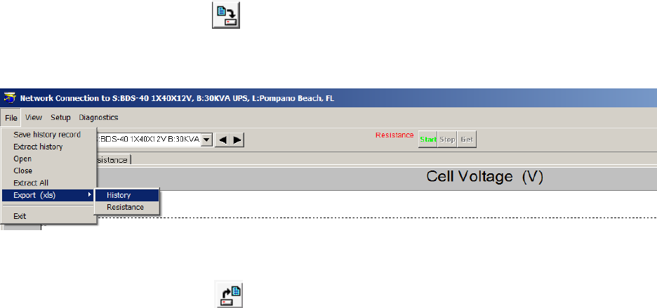
Viewing Battery and Monitor Status
21-10
21.9. Historical Graphs
String View > Cell voltage or Cell resistance or Intercell resistance
When the BMDM is displaying a String View Cell Voltage, Cell Resistance or Intercell Resistance
screen, you may save or view historical graphs.
String View > Save history record or File|Save history record
Save History Record - To save a history record of the graph and table values on the String View
screen, click Save History Record. This captures the readings, stamped with the date and time taken.
Figure 83. History Options and Record Date/Time Box
String View > Open history record or File|Open
Open - To display a historical graph and table on String View, click Open History Record, select a
date/time, and click OK. The graph and table appear, with the historical record date/time box at the
top right of the screen. You may step through historical records by clicking the left or right arrows.
String View > File|Close
Close - To close the history record and return to the active String View screen, click Close. (Do not
click the X on the upper right corner.) The historical graph, record date/time box, and left/right arrows
close.
String View > File|Extract History then (optional) File|Open|date then File|Close
Extract History - Click Extract History to have the computer extract historic float data for the string
the computer is polling. To view the extracted data, click File|Open and select the date. If a date is not
listed, no new data was extracted on that date.
String View > File|Extract All then (optional) File|Open|date then File|Close
Extract All - This function is similar to the Extract All Data button on String Status, except String
View is displaying an active connection. Click Extract All to extract historic float data, resistance
data, and discharge data for the string being polled. To view the extracted data, click File|Open and
select the date. If a date is not listed, no new data was extracted on that date.
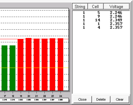
Viewing Battery and Monitor Status
21-11
String View > File|Export (xls) then History
The Export History (Voltage) function allows you to export resistance data by date and time. To
export history on resistance, from the main menu, click File, Export (xls) then History. The Select
Date/Time window appears to select the date and time of the data to be exported. The file will be
exported and saved to the following default folder: …\Alber\MPM Manager\Export\History_BDS-40
with the string configuration and the month, day, year and time. (for example; History_BDS-40
1X40X12V_02_06_12_08_15_00_am.xls). Click OK to export the file.
String View > File|Export (xls) then Resistance
The Export Resistance function allows you to export resistance data by date and time. To export
history on resistance, from the main menu, click File, Export (xls) then Resistance. The Select
Date/Time window appears to select the date and time of the data to be exported. The file will be
exported and saved to the following default folder: …\Alber\MPM Manager\Export\Resistance_BDS-
40 with the string configuration and the month, day, year and time. (for example; Resistance_BDS-40
1X40X12V_02_06_12_09_45_00_am.xls). Click OK to export the file.
21.10. Cell Voltage Box
String View > Click a bar on the graph or Alt + Click a bar on the graph
To display the numerical value of an individual cell on the String View Cell Voltage screen, click a
bar on the graph. The cell voltage value appears in the box near the top left. To display the Cell
Voltage box, hold the Alt key while clicking a bar. The Cell Voltage box opens to the right of the bar
graph.
Figure 84. Cell Voltage Box
You may create a list of cells in the Cell Voltage box and monitor the continually updated voltages.
This is convenient when monitoring a discharge. To add cells to the list, hold the Alt key and click a
cell bar. To sort the list, click the String, Cell or Voltage column header. To remove a cell from the
list, click the cell listing to highlight it, then click Delete. To remove all cells from the list, click
Clear. To close the box, click Close.
21.11. Trend Analysis
String View > Click a bar to make it gray; right click the bar; Trend|Cell or Average
To perform a voltage, resistance or intercell resistance trend analysis for a cell, click a bar of interest
on the graph to change it to gray, then right click the same bar to display a pop-up menu.
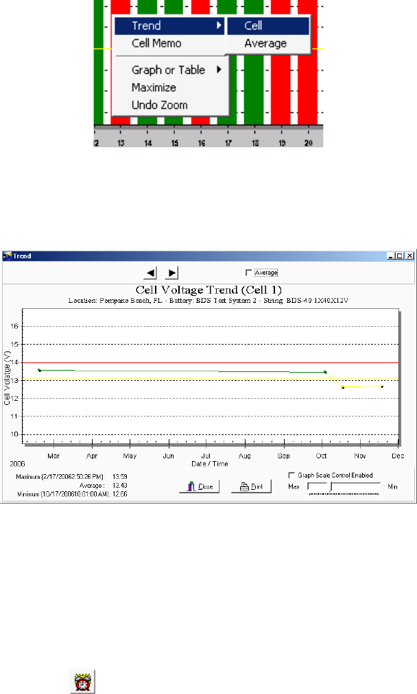
Viewing Battery and Monitor Status
21-12
Figure 85. Trend Menu
On the pop-up menu, click Trend then Cell or Average to display the trend analysis graph. If the
trend analysis box has active Previous/Next Parameter arrows, you may click them to view other
cells. All trend analysis screens have a Print button.
Figure 86. Trend - Cell Voltage (Typical of all Trend screens)
To use the Graph Scale Control to vary the y-axis scale on the graph, click the Graph Scale Control
Enabled check box. This keeps the y-axis the same when viewing other cells. To determine a data
point numerical value (in volts or ohms) and date and time for an event on the graph, click a dot on
the graph. The value appears on the upper left. Right click a graph to change display features, such as
font size, shadows, numeric precision or grid. The Average check box averages the readings.
21.12. Alarm Data
String View > View alarm or View|Alarm
The MPM or BDS monitor constantly checks threshold values set under Battery Setup. As long as
alarms are enabled, the monitor creates a record of thresholds violated. Click View Alarm to display
alarm screens.
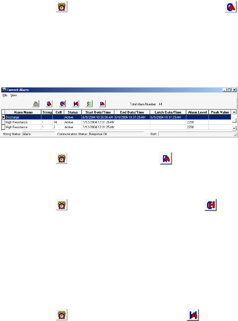
Viewing Battery and Monitor Status
21-13
String View > View alarm or View|Alarm then, if not displayed, Get current alarms or
View|Current Alarm
The Current Alarms screen indicates Active or Latched for the alarm contacts. Active indicates a
parameter is presently violating a threshold. The screen displays the alarm name and start time.
Latched indicates the parameter returned to normal, but the alarm relay must be reset. The end time
indicates when the alarm event changed to a latched state. Peak Value lists the highest or lowest value
reached during the event. For latch to function, enable the latch under Battery Setup for each
parameter. If latch is not selected, the alarm contact de-energizes when the parameter returns to
normal. A record of a present alarm is saved as a Current Historical Alarm.
Figure 87. Current Alarm List
String View > View alarm or View|Alarm then Reset alarm or View|Reset Alarm
When you select Alarm, active or latched alarms in the monitor are retrieved. These alarms stay
active until the condition clears or you click Reset Alarm. However, if you click Reset Alarm and the
violation still exists, the alarm reappears in the Current Alarm list.
String View > View alarm or View|Alarm then Get current historical alarms or
View|Current historical alarm
The Current Historical Alarm screen displays alarms that reset or cleared on their own and were not
set to latch. Select Current Historical Alarm to retrieve the alarms still in monitor memory. Normal
indicates the alarm returned to a valid value on its own. No reset date or time is displayed. If an alarm
exists and it is reset, an entry is created in Current Historical Alarms at the reset time, and a new
alarm is created because the alarm condition still exists. Reset indicates a latched alarm was reset.
The reset date and time column indicates when the reset occurred. Peak Value lists the highest or
lowest value the parameter reached during the event. When you select Current Historical Alarm, data
is transferred from the monitor to the database and saved under Historical Alarms. If you select
Current Historical Alarm using a Central computer, the current history data is permanently removed
from the monitor.
String View > View alarm or View|Alarm then View historical alarms or
View|Historical alarm
The Historical Alarm screen shows a history of alarms transferred to the computer database using
Current Historical Alarm. Select Historical Alarm to display a list of alarm events that pertain to the
battery and are saved in the database.
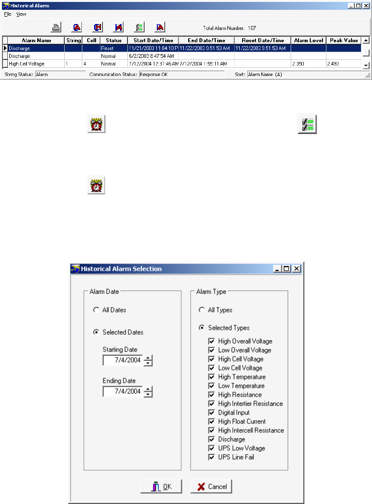
Viewing Battery and Monitor Status
21-14
Figure 88. Historical Alarm List
String View > View alarm or View|Alarm then Select historical alarms or View|Selection
If any alarm records exist, select Selection to display the Historical Alarm Selection dialog box, then
choose alarm filters, such as All Dates or Selected Types, so only alarms of interest appear.
String View > View alarm or View|Alarm then File|Delete or File|Delete All
To delete an alarm from the database, highlight the alarm line, then select File|Delete. To delete all
alarms for the string, select File|Delete All. If the Historical Alarm list is filtered using the Historical
Alarm Selection box, selecting Delete All will delete all alarms in the database, not just those listed
on the screen.
Figure 89. Historical Alarm Selection
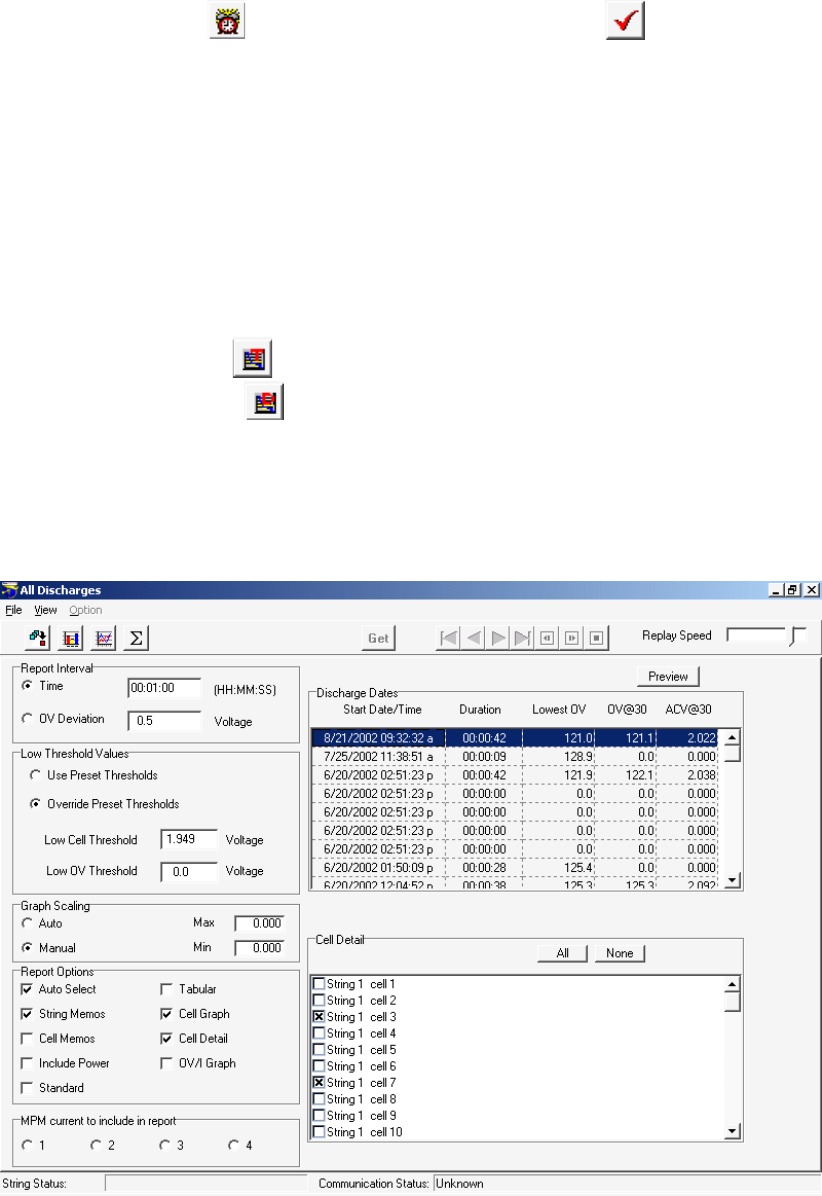
Viewing Battery and Monitor Status
21-15
21.13. Alarm Acknowledge
String View > View alarm or View|Alarm then Acknowledge alarm
If the alarm acknowledge options are selected on Setup|System|Reporting and Setup|Battery|General,
the Acknowledge Alarm button appears on the Current Alarm screen, and, to indicate an alarm event,
the String Status screen displays Acknowledge in the String Status column. You may acknowledge
alarms three ways:
1. Press the alarm reset button on the MPM or BDS monitor, or
2. On the Current Alarm screen, click the Acknowledge Alarm button, or
3. On the String Status screen, right click the mouse and click Acknowledge Alarm on the pop-up
menu.
21.14. Discharge Data
String View > View load test or View|Load test
String View > View discharge or View|Discharge
Click Load Test (MPM only) or Discharge to display the All Load Tests or All Discharges screens,
which list records of load tests or discharges for the connected string. View Load Test lists discharges
detected by user-programmed tests. View Discharge lists automatically detected discharges. If String
Status on the bottom left of the String View screen indicates Discharging, Logging Discharge Data or
R-test in Progress, View Discharge and View Load Test cannot be selected.
Figure 90. All Discharges (MPM shown)
Viewing Battery and Monitor Status
21-16
The BDS and MPM All Discharges screens are similar, except the MPM screen has the
MPM Current to Include in Report selection. The View|Load Test and View|Discharge screens are
the same, except View|Load Test has the Start, Stop and Get buttons available.
Report Interval area - Click Time or OV Deviation and type a value in the box. The Report Interval
determines the frequency of report sampling. If Time is selected, replay time advances in increments
measured against real-time. For example, if 00:10 is entered, playback advances 10 seconds every
second. If Overall Voltage is selected, playback advances each time the voltage changes. For
example, if 0.1 is entered, playback advances each time a 100mv deviation in overall voltage occurs.
Specify time in hours, minutes, and seconds (10 second minimum) or OV (overall voltage) deviation
in volts (0.2 volt minimum).
Click Use Preset Thresholds to use values set in the BMDM program when the test was run.
Click Override Preset Thresholds to ignore BMDM thresholds, then type values in the Low Cell
Threshold and Low OV Threshold boxes to identify cells that exceed critical levels. Any
measurement below these values will be in violation.
Graph Scaling area - Click Auto to default to automatic graph scaling, or click Manual and type
the Max and Min graph scale values. Use Manual scaling when you want to maintain scaling to make
it easier to compare several graphs.
Select Auto Select to automatically select cells listed on the right side that violate the thresholds. If
you change the cell or OV thresholds, cells that meet the new criteria are selected. You may add cells
to the report by selecting additional check boxes in the list.
Select String Memos and Cell Memos to include string and cell memos.
Select Include Power to list power in reports, in addition to voltage and current.
Select Standard to create a standard report. Cells are listed by string, and strings are listed by time in
a Cell = Value format.
Select Tabular to create a tabular report, which is the same as a standard report, but in a spreadsheet
format, with Cells vs. Time.
Click Cell Graph to create a report that includes a cell graph.
Click Cell Detail to create a report that includes cell detail.
Click OV/I Graph to create a report that includes Overall Voltage and Load Current graphs.
MPM Current to Include in Report (MPM only) - Choose up to four current channels Current 1 to
Current 4 to view simultaneously if they are connected.
The Discharge Dates columns list the Start Date/Time, Duration, Lowest OV, OV@30 and
ACV@30 of all discharges. The Lowest OV column lists the lowest value reached during discharge.
OV@30 lists the overall voltage 30 seconds into discharge, and ACV@30 lists the average cell
voltage 30 seconds into discharge. Click the discharge for which the report will be generated. Only
one discharge date may be selected for a report.

Viewing Battery and Monitor Status
21-17
Cell Detail area - To manually select cells to include in the report, click the cells in the list or click
All to select all items. If Auto Select is selected, cells that violate thresholds are already selected. To
clear all selected items, click None. If more than one subdirectory of cell data is available, tabs for
each subdirectory appear above the list of cell names.
After all options are selected, click the Preview button to create a report and display it on the Preview
screen. Refer to Using the Preview Screens.
Adjust the Replay Speed slider to have a replay run faster or slower. You may do this while the
replay is in process.
String View > Start resistance test or Stop resistance test or Get test results
If View|Load Test was selected, to start a load test and capture new readings, click Start. After the
Test in Progress message disappears, the Get button becomes active. Click Get to retrieve the
readings and transfer them to the computer. To stop the test before completion, click Stop.
If View|Discharge was selected, to retrieve new discharge readings, click Get to display the readings
and transfer them to the computer. You cannot start a discharge test from this screen.
Options selected on the All Discharge screen are saved by the battery name.
After selecting a discharge from the list by clicking it, you can perform two types of analysis. Click
Discharge Replay to play back the discharge. Click Discharge Curve to display line graphs of up to
three specified parameters.
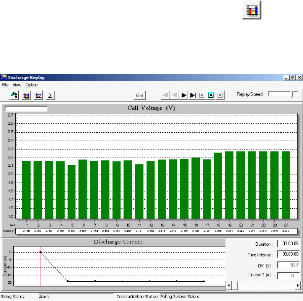
Viewing Battery and Monitor Status
21-18
21.14.1. Discharge Replay
String View > View|Load test or Discharge then Discharge replay
or View|Discharge Replay
Click the Discharge Replay button to display the Discharge Replay screen, which shows the
variations of cell levels over time.
Figure 91. Discharge Replay
Play Buttons: Show First, Show Previous, Show Next, Show Last, Replay Backward,
Replay Forward and Stop
The play buttons are at the top of the screen. Click Replay Forward to play the discharge. The
display advances either by time or voltage at the rate selected. Move the Replay Speed slider at
the upper right to increase or decrease replay speed.
You can click a point on the lower graph or move the Change Elapsed Time slider at the lower
right to cause the bar graph to display the cell voltages for the time selected. The Duration, Time
Interval, Overall Voltage, and Current are indicated above the slider.
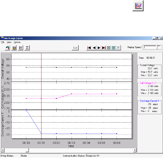
Viewing Battery and Monitor Status
21-19
21.14.2. Discharge Curve
String View > View|Load test or Discharge then Discharge curve or View|Discharge Curve
Click Discharge Curve to display the Discharge Curve screen, which shows the relationship of
the Overall Voltage, Discharge Current, and Cell Voltages on a graph.
Figure 92. Discharge Curve
Play Buttons: Show First, Show Previous, Show Next, Show Last, Replay Backward,
Replay Forward and Stop
The play buttons are at the top of the screen. Click Replay Forward to play the discharge. The
display advances either by time or voltage at the rate selected. Move the Replay Speed slider at
the upper right to increase or decrease replay speed.
You can click a point on the graph or move the Change Time slider on the bottom to display
readings for the time selected. The Overall Voltage, Cell Voltage and Discharge Current values
are to the right of the graph.
String View > View|Load test or Discharge then View|Discharge Curve|Option|Curve Option
On the Discharge Curve screen, select Option|Curve Option to display the Curve Option dialog
box, which lets you select up to three parameters for viewing.
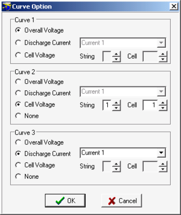
Viewing Battery and Monitor Status
21-20
Figure 93. Curve Option
In Curve 1, 2 or 3, select Overall Voltage, Discharge Current or Cell Voltage curves. If you select
Discharge Current, choose a Current (for string) 1, 2, 3 or 4 from the drop-down list. The MPM
has strings 1 to 4 available; the BDS has only string 1.
If you select Cell Voltage, choose a string and cell number. If an invalid current, string or cell
number is selected, the area appears on the Discharge Curve screen, but no curve is displayed. If
you select None in Subset 2 or 3, the area does not appear.
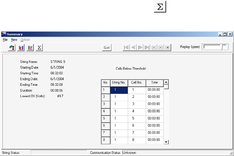
Viewing Battery and Monitor Status
21-21
21.14.3. Summary
String View > View|Load test or Discharge then Summary or View|Summary
Select Summary to display the Summary screen.
Figure 94. Summary (Discharges)
This screen summarizes the following information.
The String Name selected on the String Status screen.
The Starting Date and Starting Time the discharge or load test began.
The Ending Date and Ending Time the discharge or load test stopped.
The Duration of the test.
The Lowest OV (Volts) reached during the discharge or load test.
If any cells went below the threshold level during the test, Cells Below Threshold displays a
table that lists the String Number, Cell Number, and Time the cell went below threshold.
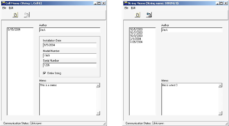
Viewing Battery and Monitor Status
21-22
21.15. Cell Memo / String Memo
Cell Memo or String Memo saves notes for a cell or string to the database using a Local, Central or
Service computer. A Service computer can store a string memo in the monitor, but not a cell memo.
The Service computer saves the string memo in the database and monitor memory; the memo is
removed from monitor memory if manually imported or the Central computer performs an automatic
data extraction.
String View > Click a bar to make it gray, then right click the bar | Cell Memo or View|Cell Memo
To create a cell memo, click a bar on the graph to change it to gray, then right click the bar. On the
pop-up menu, click Cell Memo. On the Cell Memo dialog box, click the New button and type the data
and memo. To have the installation date, model, and serial number apply to all cells in the string,
select Entire String. To save the memo, click Save. If Entire String was checked, when you select Cell
Memo and click New for another cell, the installation date, model number, and serial number appear.
To determine which cells have cell memos assigned, press the F5 key. Cell bars with memos assigned
display in blue.
String View > View|String Memo
To create a string memo, click String Memo. On the String Memo dialog box, type a global memo
that applies to the entire string. To save the memo, click Save. To import a string memo into the
Central computer database that was entered into the monitor using a Service computer, on the String
Memo dialog box, select File|Import. This removes the memo from monitor memory.
Figure 95. Cell Memo and String Memo
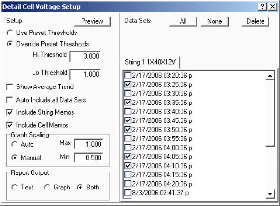
Using the Report Generator
22-1
22. Using the Report Generator
The BMDM Report Generator uses BMDM data files to create reports. After a BMDM-controlled
system reads voltage or resistance, the data is saved, and it is this data, presented in report format,
that battery monitoring personnel use to analyze battery system performance. The Report
Generator displays and prints text and graphs and saves customized reports in an archive ZRF
format that protects against changes. You may also view and print ZRF files using the Archive
Reader program.
String View > View|Reports|item
View|Reports accesses eleven Report Generator setup boxes. Use these boxes to create Detail and
Trend reports. Choose a Detail report to generate a report on an entire string by date. Choose
Trend to report on an individual cell or cells, temperature or overall voltage over a range of dates.
Some report dialog boxes let you select data sets. A data set is a set of historical float voltages,
resistance readings, alarm readings and/or discharge data for a string. A data set is for a single
date and time, and all data is displayed in one report.
After you select all the options on a Setup dialog box, click the Preview button to create a report
and display it on the Preview screen. Refer to Using the Preview Screens.
22.1. Detail Cell Voltage Report
String View > View|Reports|Detail|Cell Voltage
To create a Detail Cell Voltage report, click Cell Voltage. The Detail Cell Voltage Setup box
appears.
Figure 96. Detail Cell Voltage Setup
Click Use Preset Thresholds to use values set in the BMDM program when the test was run.
To ignore BMDM thresholds, click Override Preset Thresholds, then type values in
the Hi Threshold and Lo Threshold boxes.
Using the Report Generator
22-2
Select Show Average Trend to generate a graph that shows the average voltage of all the
cells in the string for each date selected.
Select Auto Include All Data Sets to automatically select string data sets listed on the right
side that violate high or low thresholds. If you change threshold values, data sets that meet
the new criteria are selected. You may add data sets to the report by selecting additional
check boxes in the list.
Select Include String Memos or Include Cell Memos to include string or cell memos.
Graph Scaling area - Click Auto to default to automatic graph scaling, or click Manual and
type the Max and Min graph scale values. Use Manual scaling when you want to maintain
scaling to make it easier to compare several graphs.
Report Output area - Click Text to create a report with text only; click Graph for graphs
only. Click Both to include both text and graphs in the report.
Data Sets area - To manually select string data sets to include in the report, click the data sets
in the list or click All to select all items. If Auto Include All Data Sets is selected, strings that
violate thresholds are already selected. To clear all selected items, click None. To delete all
selected items from the database, click Delete. If the selected range contains no data, no dates
appear under Data Sets.
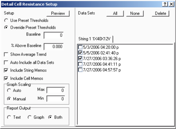
Using the Report Generator
22-3
22.2. Detail Cell Resistance Report
String View > View|Reports|Detail|Cell Resistance
To create a Detail Cell Resistance report, click Cell Resistance. The Detail Cell Resistance
Setup box appears.
Figure 97. Detail Cell Resistance Setup
The items on the Detail Cell Resistance Setup box are the same as those on the Detail Cell
Voltage Setup box (refer to Detail Cell Voltage Report), with the following exceptions.
To ignore BMDM thresholds, click Override Preset Thresholds. In the Baseline box, type
the resistance in microhms. In the % Above Baseline box, type the percentage above which a
measurement will be in violation. For example, if the baseline resistance is 300 microhms and
the percentage is 10%, any data above 330 microhms violates threshold.
Select Show Average Trend to generate a graph that shows the average resistance of all the
cells in the string for each date selected.
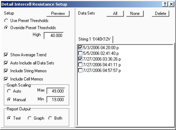
Using the Report Generator
22-4
22.3. Detail Intercell Resistance Report
String View > View|Reports|Detail|Intercell Resistance
To create a Detail Intercell Resistance report, click Intercell Resistance. The Detail Intercell
Resistance Setup box appears.
Figure 98. Detail Intercell Resistance Setup
The items on the Detail Intercell Resistance Setup box are the same as those on the Detail
Cell Voltage Setup box (refer to Detail Cell Voltage Report), with the following exceptions.
To ignore BMDM thresholds, click Override Preset Thresholds, then type a high intercell
resistance value in the High box.
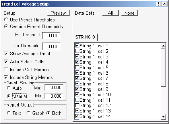
Using the Report Generator
22-5
22.4. Trend Cell Voltage Report
String View > View|Reports|Trend|Cell Voltage
To create a Trend Cell Voltage report, click Cell Voltage. The Trend Cell Voltage Setup box
appears.
Figure 99. Trend Cell Voltage Setup
Click Use Preset Thresholds to use values set in the database.
Click Override Preset Thresholds to ignore BMDM thresholds, then type values in
the Hi Threshold and Lo Threshold boxes.
Select Show Average Trend to generate a graph that shows the average cell voltage over the
range of dates.
Select Auto Select Cells to automatically select cells listed on the right side that violate high
or low thresholds. If you change threshold values, cells that meet the new criteria are
selected. You may add cells to the report by selecting additional check boxes in the list.
Select Include Cell Memos and Include String Memos to include cell and string memos.
Graph Scaling area - Click Auto to default to automatic graph scaling, or click Manual and
type the Max and Min graph scale values. Use Manual scaling when you want to maintain
scaling to make it easier to compare several graphs.
Report Output area - Click Text to create a report with text only; click Graph for graphs
only. Click Both to include both text and graphs in the report.
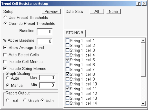
Using the Report Generator
22-6
Data Sets area - To manually select cells to include in the report, click the cells in the list or
click All to select all items. If Auto Select Cells is selected, cells that violate thresholds are
already selected. To clear all selected items, click None. If the BMDM was used with an
MPM, the list shows string and cell. If a BDS was used, the list shows cell only. If the
selected range contains no data, no cells appear under Data Sets.
22.5. Trend Cell Resistance Report
String View > View|Reports|Trend|Cell Resistance
To create a Trend Cell Resistance report, click Cell Resistance. The Trend Cell Resistance
Setup box appears.
Figure 100. Trend Cell Resistance Setup
The items on the Trend Cell Resistance Setup box are the same as those in Trend Cell
Voltage Report, with the following exceptions.
To ignore BMDM thresholds, click Override Preset Thresholds. In the Baseline box, type
the resistance in microhms. In the % Above Baseline box, type the percentage above which a
measurement will be in violation. For example, if the baseline resistance is 300 microhms and
the percentage is 10%, any data above 330 microhms violates threshold.
Select Show Average Trend to generate a graph that shows the average cell resistance over
the range of dates.
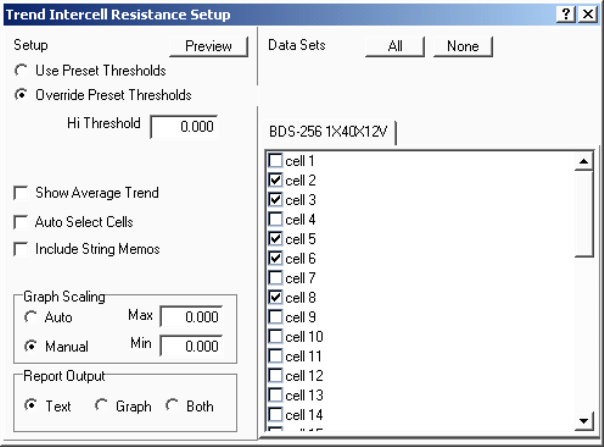
Using the Report Generator
22-7
22.6. Trend Intercell Report
String View > View|Reports|Trend|Intercell
To create a Trend Intercell report, click Intercell. The Trend Intercell Resistance Setup box
appears.
Figure 101. Trend Intercell Resistance Setup
The items on the Trend Intercell Resistance Setup box are the same as those in Trend Cell
Voltage Report, except that Trend Intercell Resistance Setup does not have check boxes for
Low Threshold or for Include Cell Memos.
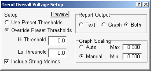
Using the Report Generator
22-8
22.7. Trend Overall Voltage Report
String View > View|Reports|Trend|Overall Voltage
To create a Trend Overall Voltage report, click Overall Voltage. The Trend Overall Voltage
Setup box appears.
Figure 102. Trend Overall Voltage Setup
Click Use Preset Thresholds to use values set in the database.
Click Override Preset Thresholds to ignore BMDM thresholds, then type values in
the Hi Threshold and Lo Threshold boxes.
Select Include String Memos to include string memos.
Report Output area - Click Text to create a report with text only; click Graph for graphs
only. Click Both to include both text and graphs in the report.
Graph Scaling area - Click Auto to default to automatic graph scaling, or click Manual and
type the Max and Min graph scale values. Use Manual scaling when you want to maintain
scaling to make it easier to compare several graphs.
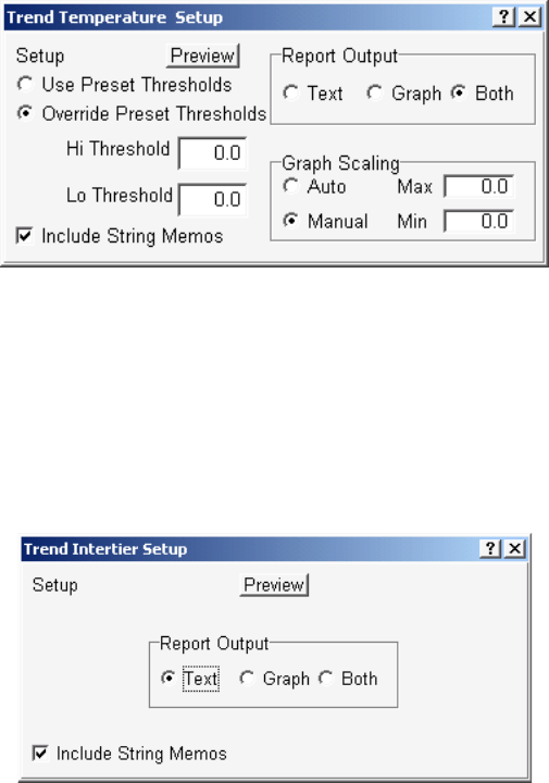
Using the Report Generator
22-9
22.8. Trend Temperature Report
String View > View|Reports|Trend|Temperature
To create a Trend Temperature report, click Temperature. The Trend Temperature Setup box
appears.
Figure 103. Trend Temperature Setup
The items on the Trend Temperature Setup box are the same as those in Trend Overall
Voltage Report.
22.9. Trend Intertier Report
String View > View|Reports|Trend|Intertier
To create a Trend Intertier report, click Intertier. The Trend Intertier Setup box appears.
Figure 104. Trend Intertier Setup
Report Output area - Click Text to create a report with text only; click Graph for graphs
only. Click Both to include both text and graphs in the report.
Select Include String Memos to include string memos.
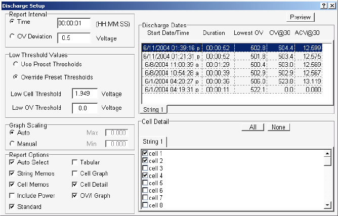
Using the Report Generator
22-10
22.10. Discharge Report
String View > View|Reports|Discharge
To create a Discharge report, click Discharge. The Discharge Setup box appears. Options
selected on Discharge Setup are saved by the battery name.
Figure 105. Discharge Setup
Report Interval area - Click Time or OV (Overall Voltage) Deviation and type a value in
the respective box. Report Interval determines the frequency of report sampling. Specify time
in hours, minutes, and seconds (10 second minimum) or OV deviation in volts (0.2 volt
minimum).
Low Threshold Values area - Click Use Preset Thresholds to use values set in the BMDM
program when the test was run. Click Override Preset Thresholds to ignore BMDM
thresholds, then type values in the Low Cell Threshold and Low OV Threshold boxes. Any
measurement below these values will be in violation.
Graph Scaling area - Click Auto to default to automatic graph scaling, or click Manual and
type the Max and Min graph scale values. Use Manual scaling when you want to maintain
scaling to make it easier to compare several graphs.
Select Auto Select to automatically select cells listed on the right side that violate thresholds.
If you change cell or OV threshold values, cells that meet the new criteria are selected. You
may add cells to the report by selecting additional check boxes in the list.
Select String Memos and Cell Memos to include string memos and cell memos.
Select Include Power to list power in reports, in addition to voltage and current.
Select Standard to create a Standard report. Cells are listed by string, and strings are listed
by time in a Cell = Value format.
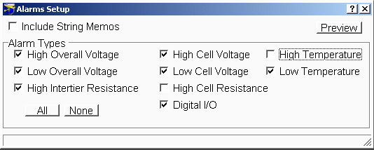
Using the Report Generator
22-11
Select Tabular to create a Tabular report, which is the same as a standard report, but in a
spreadsheet format, with Cells vs. Time.
Click Cell Graph to create a report that includes a cell graph.
Click Cell Detail to create a report that includes cell detail.
Click OV/I Graph to create a report that includes Overall Voltage and Load Current graphs.
The Discharge Dates columns list the Start Date/Time, Duration, Lowest OV, OV@30 and
ACV@30 of all discharges. The Lowest OV column lists the lowest value reached during
discharge. OV@30 lists the overall voltage 30 seconds into discharge, and ACV@30 lists the
average cell voltage 30 seconds into discharge. Click the discharge for which the report will
be generated. Only one discharge date may be selected for a report.
Cell Detail area - To manually select cells to include in the report, click the cells in the list or
click All to select all items. If Auto Select is selected, cells that violate thresholds are already
selected. To clear all selected items, click None. If more than one subdirectory of cell data is
available, tabs for each subdirectory appear above the list of cell names.
22.11. Alarm Report
String View > View|Reports|Alarm
To create an Alarm report, click Alarm. The Alarms Setup box appears. Options selected on
Alarms Setup are saved by the battery name.
Figure 106. Alarms Setup
Select Include String Memos to include string memos in the report.
Alarm Types area - Alarm types that you may include in the report are high and low overall
voltage, high intertier resistance, high and low cell voltage, high cell resistance, and high and
low temperature. Select these items to include full details of each alarm, not just a summary.
If Digital I/O is selected, the system generates an alarm if a digital input is selected on the
battery setup digital output screen.
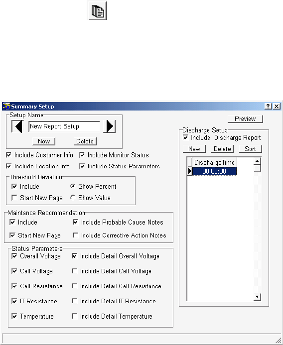
Using the Report Generator
22-12
22.12. Summary Report
String Status > Summary report or String View > View|Reports|Summary [see text]
To create a Summary report that includes data only for the string to which the system is
connected, click View|Reports|Summary (String View screen). To create a Summary report
for all strings in the system, click the Summary Report button (String Status screen). The
Summary Setup box appears. A report generated using the Summary Report button may be
more than 100 printed pages long.
Figure 107. Summary Setup
Setup Name area - You can save the options and discharge times as a template, so you do not
have to choose them each time you generate a report. After choosing the options, type a name
in the Setup Name box and click New to save the template. To view existing templates, click
the arrows. To delete a template, display it and click Delete. Although the same name can be
used for different templates, you may want to use a unique name for each template.
Select Include Customer Info and Include Location Info to include the customer and
location names, addresses, and contact information in the report.
Select Include Monitor Status to print Last Known Status, which lists string name, monitor
status string status, and the date and time of the last known status.
Select Include Status Parameters to print Parameter Status as of Last Reading, which lists
the following if they are checked under Status Parameters: overall voltage, low and high cell
voltage and cell resistance, highest intertier resistance, and average temperature.
Using the Report Generator
22-13
Threshold Deviation area - Select Include to include the threshold deviation report. Select
Start New Page to insert a page break before the report. Select Show Percent or Show
Value to have deviations shown as percent change or actual values. Only cells that exceed
threshold values are listed.
Maintenance Recommendation area - Select Include to include the maintenance
recommendation report. Select Start New Page to insert a page break before the report.
Select Include Probable Cause Notes and Include Corrective Action Notes to include text
that attempts to resolve the types of violations found, such as high resistance. Only cells with
violations are listed.
Status Parameters area - Select Overall Voltage, Cell Voltage, Cell Resistance, IT
(Intertier) Resistance or Temperature to list these items in Parameter Status as of Last
Reading. You must also select the Include Status Parameters check box.
Select Include Detail Overall Voltage, Include Detail Cell Voltage, Include Detail Cell
Resistance, Include Detail IT Resistance or Include Detail Temperature to print these
sections, which have graphs of each item in violation. Items with Normal status do not print.
Discharge Setup area - Select the Include Discharge Report check box to print a discharge
report. To add a discharge duration time to the list, Click New then type a new time in the
highlighted 00:00:00 in the Discharge Time list. To sort the times, click Sort. To remove a
time from the Discharge Time list, click the time to highlight it, then click Delete.
For a description of the items in Discharges in the report, refer to Using the Web Report
Generator.
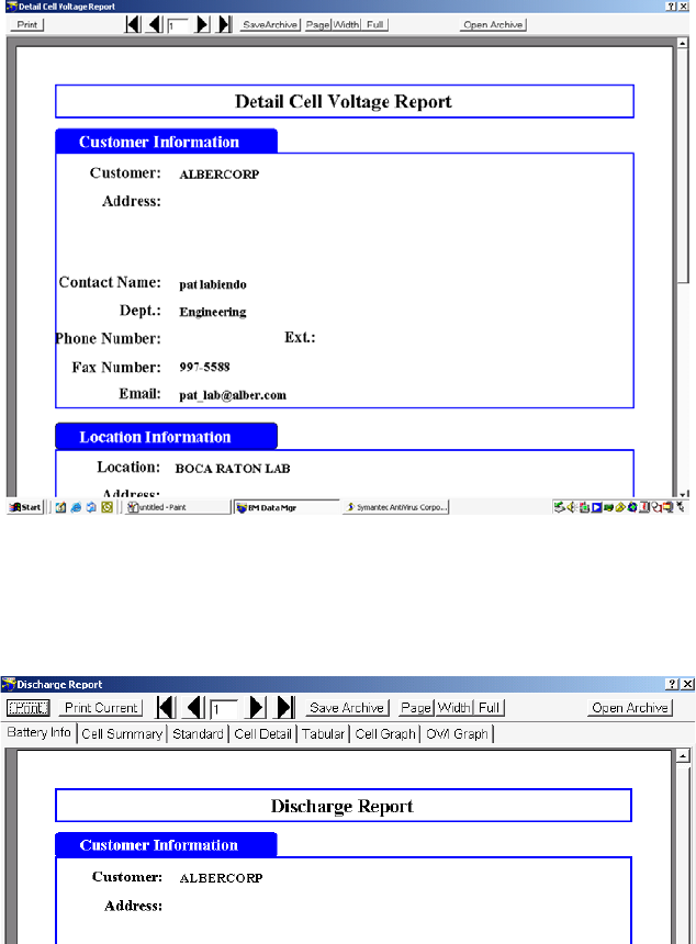
Using the Preview Screens
23-1
23. Using the Preview Screens
[Previously described Setup screen] > Preview
After all report parameters are selected, to view the report on a report preview screen,
click Preview. To change the size of the page display, click Page, Width or Full. To view
different pages, click the first, previous, next or last page arrows on the toolbar.
Figure 108. Preview (Typical Screen)
The Discharge Report preview screen is different from the other preview screens. This screen has
tabs along the top that let you select different sections of the report. These tabs are labeled Battery
Info, Cell Summary, Standard, Cell Detail, Tabular, Cell Graph, and OV/I Graph.
Figure 109. Preview (Discharge Report)
To view a section of the report, click a tab. To view different pages in one section, click the first,
previous, next or last page arrows on the toolbar.
Using the Preview Screens
23-2
23.1. Saving a Report in Archive (ZRF) Format
Preview screen > Save Archive
The Report Generator can save a report as an archive ZRF file, which cannot be changed after
it is saved. Archive format lets you distribute the report file while ensuring the integrity of the
data. The file can be opened by the Report Generator or the Archive Reader and viewed or
printed. To save a report in archive format, click Save Archive. In the Save Archive dialog
box, select the subdirectory, type the file name, then click Save. Reports are saved in the
folder last opened, unless a different folder is selected.
23.2. Printing a Report
Preview screen > Print
To print the report displayed, click Print; in reports with more than one section, to print only
the currently selected tab, click Print Current or, to print the entire report, click Print. When
the Print dialog box appears, select the pages to print, the number of copies, and the printer
setup. To print a single page, do not select Current Page. Instead, select Pages and type the
page number in the box.
23.3. Opening an Archive File
Preview screen > Open Archive
You can open an archive ZRF file to compare data before saving a currently open report. To
open and display an archive file, click Open Archive, select the subdirectory and file name,
then click Open. Use the toolbar buttons to change the page size and view different pages. To
print the report, click Print. To close the file, click the Close button. Archive files cannot be
changed.
23.4. Archive Reader Program
The Archive Reader, distributed with the Report Generator, is used to view and print ZRF
files when the Report Generator program is unavailable. It is typically sent with archive files
when these files are sent to locations that do not have the Report Generator. You may freely
copy and distribute the Archive Reader when required. The Report Generator is a licensed
product and may not be duplicated for multiple site use. You may download the Archive
Reader from the Albér Web site at www.alber.com and copy it to a CD for distribution with
ZRF files.
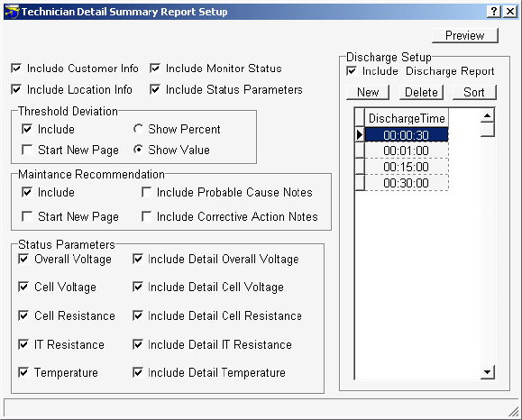
Using the Web Report Generator
24-1
24. Using the Web Report Generator
Every 24 hours, the Web Report Generator automatically creates and saves an executive summary
report as a PDF file at Program Files\Alber\MPM Manager\Web\SystemSummary. New reports
overwrite previous reports automatically or when you manually generate a report. You may view
the executive summary report by connecting via the Web to albermonitor.com.
24.1. Setting Up the Web Report
String Status > highlight a name then Reports|Setup
To enable automatic Web report generation, select the Detail Executive Report Enable check
box on Setup|Preferences. To set up report format, highlight a string name on String Status,
then click Reports|Setup to open the Technician Detail Summary Report Setup dialog box.
Figure 110. Technician Detail Summary Report Setup
Select Include Customer Info and Include Location Info to include the customer and
location names, addresses, and contact information in the report.
Select Include Monitor Status to print Last Known Status, which lists string name, monitor
status, string status, and the date and time of the last known status.
Select Include Status Parameters to print Parameter Status as of Last Reading, which lists
the following if they are checked under Status Parameters: overall voltage, low and high cell
voltage and cell resistance, highest intertier resistance, and average temperature.
Threshold Deviation area - Select Include to include the threshold deviation report. Select
Start New Page to insert a page break before the report. Select Show Percent or
Show Value to have deviations shown as percent change or actual values. Only cells that
exceed threshold values are listed.
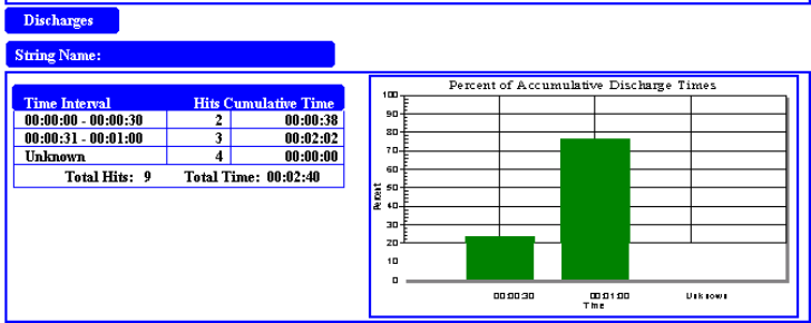
Using the Web Report Generator
24-2
Maintenance Recommendation area - Select Include to include the maintenance
recommendation report. Select Start New Page to insert a page break before the report.
Select Include Probable Cause Notes and Include Corrective Action Notes to include text
that offers solutions for the types of violations found, such as high resistance. Only cells with
violations are listed.
Status Parameters area - Select Overall Voltage, Cell Voltage, Cell Resistance, IT
(Intertier) Resistance or Temperature to list these items in Parameter Status as of Last
Reading. You must also select the Include Status Parameters check box.
Select Include Detail Overall Voltage, Include Detail Cell Voltage, Include Detail Cell
Resistance, Include Detail IT Resistance or Include Detail Temperature to print these
sections, which have graphs of each item in violation. Items with Normal status do not print.
Discharge Setup area - Select the Include Discharge Report check box to print a discharge
report. To add a discharge duration time to the list, Click New then type a new time in the
highlighted 00:00:00 in the Discharge Time list. To sort the times, click Sort. To remove a
time from the Discharge Time list, click the time to highlight it, then click Delete.
Figure 111. Technician Report - Discharges Area
The Discharges area on the report has a table and graph. The Time Interval column lists
discharge duration limits. For example, if the time listed is 00:00:00 - 00:00:30 and the Hits
column shows 2, then there were two discharges that lasted somewhere between 0 and 30
seconds. In the preceding figure, the cumulative (total) time of the two discharges was 38
seconds.
The graph in the Percent of Accumulative Discharge Times classifies the various discharge
durations. In the above figure, 24% of the total discharge time were discharges of zero to 30
seconds, and 76% were discharges 31 seconds to one minute.
After selecting all options, click the Preview button to create and display a report. If you
click Save Archive on the Preview screen, you can save to the Reports subdirectory as a ZRF
file and not overwrite the automatically generated report in the SystemSummary
subdirectory. For more on the Preview screen buttons, refer to Using the Preview Screens.
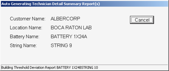
Using the Web Report Generator
24-3
24.2. Generating an Executive Summary Report
String Status > Reports|Generate
If enabled on Setup|Preferences, the Web Report Generator automatically generates the
executive summary report every night after autopolling is done. To manually generate a
report, highlight a name on the String Status screen, then click Reports|Generate. At the
Generate Executive Reports box, click Yes. The Auto Generating Technician Detail
Summary Report dialog box appears while the reports are being generated.
Figure 112. Auto Generating Technician Detail Summary Report
The report is saved in the SystemSummary subdirectory, which is created when the BMDM
program is installed. To view the new report, use a program such as Adobe Acrobat Reader
and navigate to Program Files\Alber\MPM Manager\Web\ SystemSummary. Click on the
PDF file name to open the report.
New executive summary reports automatically overwrite previous reports every 24 hours or
when you manually generate reports by selecting Reports|Generate.
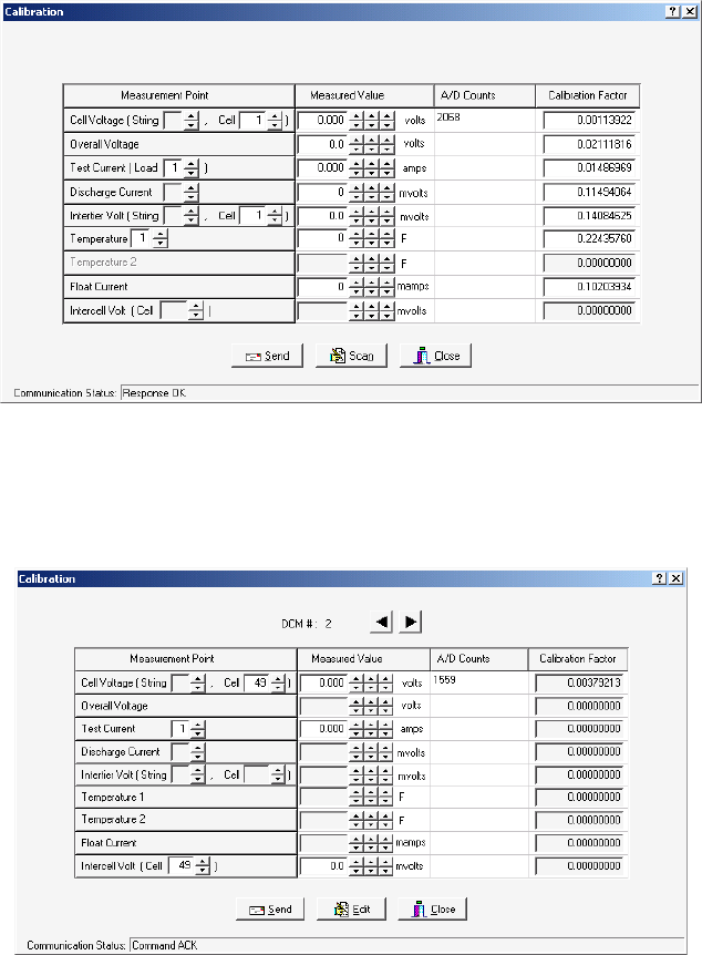
Calibration
25-1
25. Calibration
String View > Setup|Calibration
To ensure reliability of readings, Albér recommends that a qualified technician check MPM or
BDS monitor calibration annually. Perform calibration using a computer directly connected via
the RS-232 port. The Calibration dialog box displays all the parameters the unit monitors. To
display this screen, select Setup|Calibration from the String View screen.
Figure 113. Calibration Setup (MPM)
The BDS Calibration dialog box differs slightly. It has arrows to select other DCM's and does not
have a Test Current cell selector. Overall Voltage and Intercell Volt are not available for the
BDS-40.
Figure 114. Calibration Setup (BDS)
Calibration
25-2
There are four columns on the Calibration dialog box: Measurement Point, Measured Value,
A/D Counts, and Calibration Factor.
Measurement Point – Allows selection of input channels when calibrating. Usually, the
parameters selected never need to be changed. The Measurement Point also serves as a diagnostic
tool that can lock in on a channel for troubleshooting.
Measured Value – Type measured values in this column. The MPM uses only Temperature 1;
the BDS uses two temperature channels per DCM.
A/D Counts – The value from the A/D (Analog to Digital) converter before any calibration
(Calibration Factor) is applied. Also referred to as Raw Counts.
Calibration Factor – The correction factor required to obtain a value that can be displayed on
the String View screen.
Scan / Edit is a toggle action button. Clicking Edit allows editing of the Calibration Factors.
Clicking Scan disables editing. Clicking a Measured Value field displays A/D counts.
Required Test Equipment:
4-1/2 digit DVM – Fluke 87 or equivalent.
100 millivolt and 10 millivolt source.
Clamp-on current meter. A 0.1% shunt is recommended.
Temperature probe.
The calibration procedures are available to qualified personnel trained by Albér in the calibration
of this equipment.
MPM Diagnostics
26-1
26. MPM Diagnostics
String View > Diagnostics|Item
The diagnostics are used for production testing, but may help troubleshoot a hardware failure in
the field. Select Diagnostics from String View. The computer must be connected to an MPM and
Communication Status at screen bottom must show Response OK.
26.1. Rebooting and Power Up Diagnostics (MPM)
String View > Setup|Reboot Firmware
To reboot the MPM from the Data Manager, select Reboot Firmware. This does a "warm
reset" of the MPM. At power-up, the unit performs diagnostics for about two minutes. If the
unit fails any test other than failure to detect a dial tone, the Error LED blinks. Identify the
failing parameters by using the Self Test diagnostic.
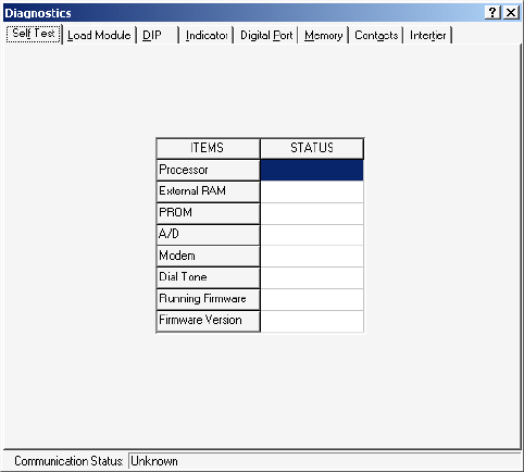
MPM Diagnostics
26-2
26.2. Self Test (MPM)
String View > Diagnostics|Self Test
Self Test reads an MPM status register and displays the parameter status on the Diagnostics
dialog box. These parameters are tested only at MPM power-up. If an update is needed, cycle
the power to the MPM or reboot by selecting Setup|Reboot Firmware. To open Self Test
Diagnostics, select Diagnostics|Self Test.
Figure 115. Diagnostics - Self Test (MPM)
Items on the Self Test Diagnostics dialog box are described below.
Processor - Checks processor internal registers and timers.
External RAM - Writes and reads to each RAM location to verify accessibility.
PROM - Calculates and verifies the program checksum in the PROM.
A/D - Reads and confirms the A/D converter reference voltage is within specification.
Modem - Verifies the modem echoes commands.
Dial Tone - Confirms the telephone is connected.
Running Firmware - Displays the memory type from which the firmware is running.
Typically, this is the PROM, but the system can upload a new version to Flash memory.
Firmware Version - Displays the version of firmware running.
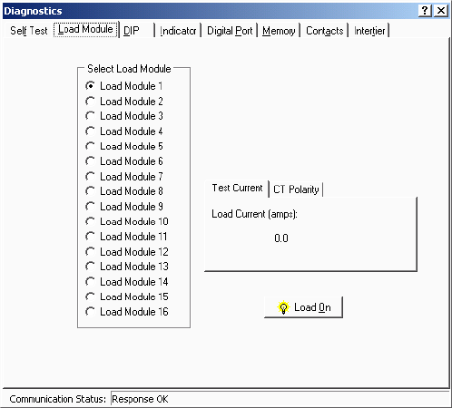
MPM Diagnostics
26-3
26.3. Load Module (MPM)
String View > Diagnostics|Load Module
The Load Module diagnostic tests each load connection to the battery. This diagnostic tests
the connections, load cable fuses, load relays and load module, and can confirm actual load
current. Refer to the left side of the load connections drawing in the installation manual to
determine the load steps used for each configuration.
The Load Module also has a diagnostic that can confirm the direction of the current
transducer.
To test each load connection, open Load Module Diagnostics, select Load Module, then click
the Test Current tab on the dialog box. Identify the configuration that applies to the
installation. You can turn on each load step and confirm the current for that step. Each load
step must be from 17 to 23 amps when energized.
WARNING: When testing, do not leave the load module on for a long time. The load
module can overheat and damage hardware if not allowed to cool between tests. The load
module automatically turns off after 10 seconds.
Figure 116. Diagnostics - Load Module - Test Current (MPM)
Under Select Load Module, select a load module, then click Load On. To stop the test,
click Load Off.
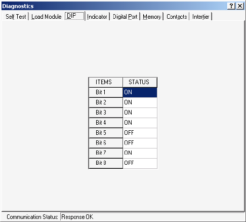
MPM Diagnostics
26-4
26.4. DIP Switch (MPM)
String View > Diagnostics|DIP Switch
The DIP Switch diagnostic confirms each position of the DIP switch inside the MPM.
Although not all switch positions are used, every position is checked. This diagnostic allows
remote checking of switch settings. To open the diagnostic, select DIP Switch. The screen
indicates each switch position as it is changed.
CAUTION: Exit this diagnostic with the switch in the same positions it was in when the
diagnostic was entered.
Figure 117. Diagnostics - DIP Switch (MPM)

MPM Diagnostics
26-5
26.5. Indicator (MPM)
String View > Diagnostics|Indicator
This diagnostic tests front panel LED operation. To open Indicator Diagnostics, select
Indicator. To activate an LED, click an LED name then On.
Figure 118. Diagnostics - Indicator (MPM)
26.6. Digital Port (MPM)
String View > Diagnostics|Digital Port
The Digital Port diagnostic checks the status of the digital inputs. If the system is connected
to external contacts, this diagnostic can check each contact. To open Digital Port Diagnostics,
select Digital Port. The screen displays the status of the inputs. An ON status means a contact
is closed.
Figure 119. Diagnostics - Digital Port (MPM)
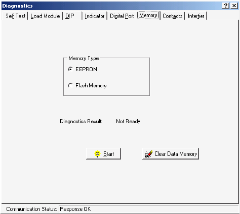
MPM Diagnostics
26-6
26.7. Memory (MPM)
String View > Diagnostics|Memory
To open Memory Diagnostics, select Memory.
Figure 120. Diagnostics - Memory (MPM)
The Memory diagnostic checks nonvolatile monitor memory: E2 (EEPROM) and Flash.
E2 memory stores calibration and setup information and data, such as Discharge, Alarm and
Resistance test data. Flash memory stores MPM firmware uploads. Firmware can be
upgraded on-site or remotely via modem.
To test memory, select EEPROM or Flash Memory, then click Start. During EEPROM
testing, communication is briefly lost, then a status result indicates pass or fail. During Flash
Memory testing, the integrity of the upgraded firmware file is checked; after clicking Start,
select a file to compare to the contents in Flash memory. Flash testing takes several minutes.
To clear all measured data stored in E2 memory, click Clear Data Memory.
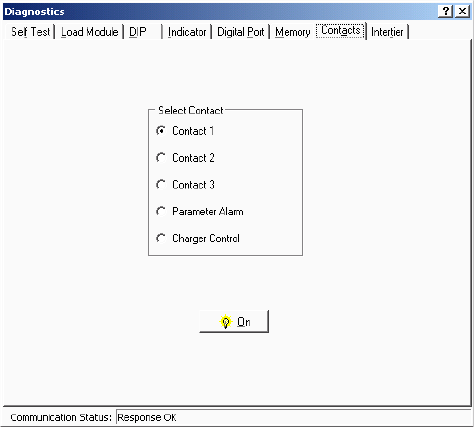
MPM Diagnostics
26-7
26.8. Contacts (MPM)
String View > Diagnostics|Contacts
This diagnostic checks the external alarm contacts, charger contacts, and optional contacts for
proper connection. To open Alarm Contacts Diagnostics, select Contacts. Under Select
Contact, click Parameter Alarm, Charger Control or Contact 1, 2 or 3, then click On. You can
confirm contact operation by verifying a device connected to the contacts turns on and off.
CAUTION: The charger contact turns the charger off until it is re-energized or until the
diagnostic is exited.
Figure 121. Diagnostics - Alarm Contacts (MPM)
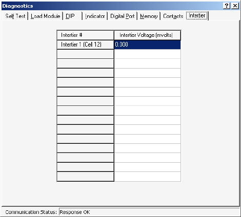
MPM Diagnostics
26-8
26.9. Intertier (MPM)
String View > Diagnostics|Intertier
The Intertier diagnostic monitors the signal on each intertier input. Use this diagnostic for
verifying the calibration of these input channels or troubleshooting. To open Intertier
Diagnostics, select Intertier.
Figure 122. Diagnostics - Intertier (MPM)
You may define up to eight intertiers for the MPM on the Battery Setup|Parameters dialog
box, but Intertiers 2 through 4 are active only when expansion ports J3, J4, J6 and J7 are
installed on the MPM.
Intertier Voltage (mvolts) - This column indicates the voltages being sent. This screen
displays up to eight intertiers for the MPM and is used to confirm calibration accuracy. The
cell number is the lower of the two cell numbers across which the intertier is connected
(selected on MPM Setup|Battery|Parameters).
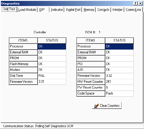
BDS Diagnostics
27-1
27. BDS Diagnostics
String View > Diagnostics|Item
The diagnostics are used for production testing, but may help troubleshoot a hardware failure in
the field. Select Diagnostics from String View. The computer must be connected to a BDS and
Communication Status at screen bottom must show Response OK.
27.1. Rebooting and Power Up Diagnostics (BDS)
String View > Setup|Reboot Firmware
To reboot the BDS from the Data Manager, select Reboot Firmware. This does a "warm
reset" of the BDS. At power-up, the unit performs diagnostics for about two minutes. If a
failure occurs, identify the failing parameters by using the Self Test diagnostic.
27.2. Self Test (BDS)
String View > Diagnostics|Self Test
Self Test reads BDS and DCM status registers and displays the parameter status on the
Diagnostics dialog box. These parameters are tested only at BDS power-up. If an update is
needed, cycle the power to the BDS or reboot by selecting Setup|Reboot Firmware. To open
Self Test Diagnostics, select Diagnostics|Self Test.
Figure 123. Diagnostics - Self Test (BDS)
Items in the Self Test Diagnostics box are described below alphabetically. If available, click
the left or right arrows to view settings for other DCM units.
A/D (DCM) - Reads and confirms the A/D converter reference voltage is within
specification.
Code Space (DCM) - Displays the memory type from which the firmware is running.
Typically, this is the PROM, but the system can upload a new version to Flash memory.
BDS Diagnostics
27-2
Dial Tone (BDS Controller) - Confirms the telephone is connected. If connected via a
multiplexer, this field indicates Failed as a normal condition.
External RAM (BDS Controller and DCM) - Writes and reads to each RAM location to
verify accessibility.
Firmware Version (BDS Controller and DCM) - Displays the version of firmware running.
Flash Memory (BDS Controller) - Calculates and verifies the program checksum in Flash
memory.
FW Reset Counter (DCM) - At boot up, the DCM runs diagnostics. If an error is found, the
DCM reboots to retest. When this happens, this counter is incremented.
HW Reset Counter (DCM) - Indicates how many times power is cycled or the DCM
performs a hardware self-reset.
Modem (BDS Controller) - Verifies the modem echoes commands.
PIO (DCM) - Checks the read/write functions of the parallel input/output device.
Processor (BDS Controller and DCM) - Checks processor internal registers and timers.
PROM (BDS Controller and DCM) - Calculates and verifies the program checksum in the
PROM.
The Clear Counters button resets the HW (hardware) and FW (firmware) counters to zero.
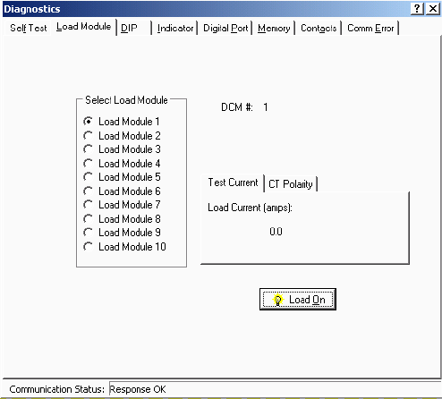
BDS Diagnostics
27-3
27.3. Load Module (BDS)
String View > Diagnostics|Load Module
The Load Module diagnostic tests each load connection to the battery. This diagnostic tests
the connections, load cable fuses, load relays and load module, and can confirm actual load
current. Depending how the system is set up, only the load module for the selected DCM is
enabled. Typically, all ten load steps are used and are distributed across multiple DCM units.
The Load Module also has a diagnostic that can confirm the direction of the current
transducer.
To test each load connection, open Load Module Diagnostics, select Load Module, then click
the Test Current tab on the dialog box. Select the DCM for the desired load module. You can
turn on each load step and confirm the current for that step.
IMPORTANT NOTE: If the screen displays only Load Module buttons 1 to 5, this indicates
the DIP switch in the DCM is set so the internal load bank is selected. This is an incorrect
state on newer DCM units. On older multiboard DCM units, this condition is normal if the
unit actually has an internal load bank. Confirm the setting before proceeding. View the
Diagnostics DIP screen. If Bank 2, Bit 1 Status is ON, this is incorrect for newer hardware.
The ON status is valid only for older hardware with internal load banks.
WARNING: When testing, do not leave the load module on for a long time. The load
module can overheat and damage hardware if not allowed to cool between tests. The load
module automatically turns off after about 10 seconds.
Figure 124. Diagnostics - Load Module - Test Current (BDS)
Under Select Load Module, select a load module, then click Load On. To stop the test,
click Load Off. Click the arrows to select other DCM units.
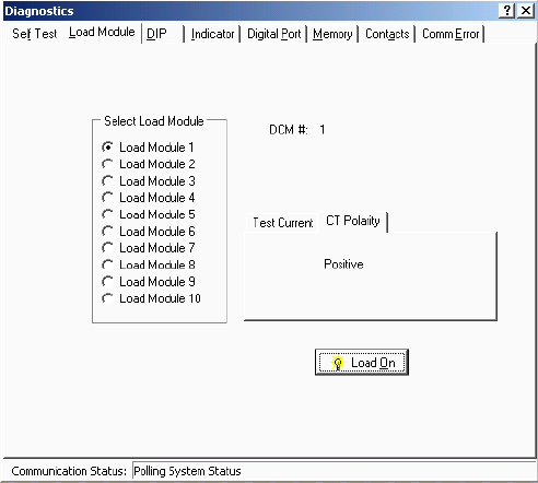
BDS Diagnostics
27-4
To run the diagnostic that can confirm the direction of the current transducer (CT), click the
CT Polarity tab on the dialog box. Select the DCM for the desired load module.
Figure 125. Diagnostics - Load Module - CT Polarity (BDS)
Under Select Load Module, select a load module, then click Load On. When the test finishes,
the dialog box indicates Correct if the CT is oriented in the proper direction. If Incorrect is
displayed, reverse the direction of the CT and perform the test again to confirm proper
orientation.
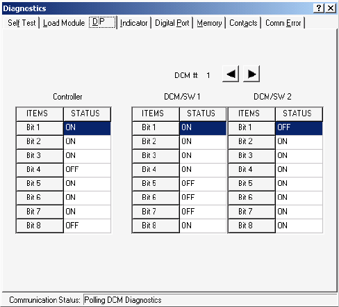
BDS Diagnostics
27-5
27.4. DIP Switch (BDS)
String View > Diagnostics|DIP Switch
The DIP Switch diagnostic confirms each position of the DIP switches inside the BDS and
DCM. This diagnostic allows remote checking of switch settings. To open the diagnostic,
select DIP Switch. The diagnostic indicates each switch position. Click the left or right
arrows to select other DCM units.
NOTE: The DIP switches are factory set and are not usually changed by the user.
Figure 126. Diagnostics - DIP Switch (BDS)
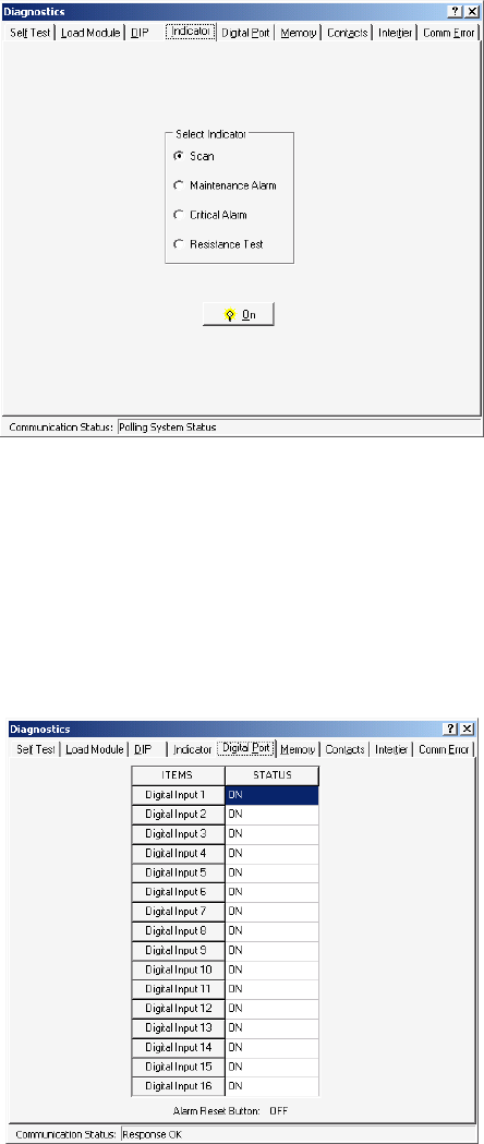
BDS Diagnostics
27-6
27.5. Indicator (BDS)
String View > Diagnostics|Indicator
This diagnostic tests front panel LED operation. To open Indicator Diagnostics, select
Indicator. To activate an LED, click an LED name then On.
Figure 127. Diagnostics - Indicator (BDS)
27.6. Digital Port (BDS)
String View > Diagnostics|Digital Port
The Digital Port diagnostic checks the status of the digital inputs. If the system is connected
to external contacts, this diagnostic can check each contact. To open Digital Port Diagnostics,
select Digital Port. The screen displays the status of the inputs. An ON status means a contact
is closed.
Figure 128. Diagnostics - Digital Port (BDS)
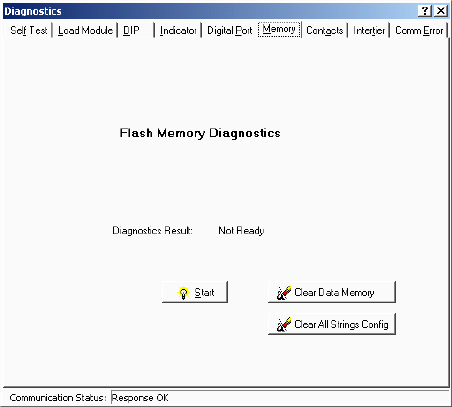
BDS Diagnostics
27-7
27.7. Memory (BDS)
String View > Diagnostics|Memory
To open Memory Diagnostics, select Memory.
Figure 129. Diagnostics - Memory (BDS)
The Memory diagnostic checks Flash memory for the integrity of the upgraded firmware file.
Flash memory stores BDS firmware uploads. Firmware can be upgraded on-site or remotely
via modem. To run this test, click Start and select a file to compare to the contents in Flash
memory. This test takes several minutes.
SRAM memory stores calibration and setup information and data, such as Discharge, Alarm
and Resistance test data. To clear all measured data stored in nonvolatile SRAM memory,
click Clear Data Memory. To clear configuration settings for all strings in the BDS
Controller hardware, click Clear All Strings Config.
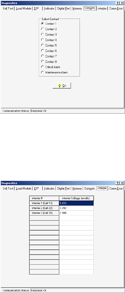
BDS Diagnostics
27-8
27.8. Contacts (BDS)
String View > Diagnostics|Contacts
This diagnostic checks the external critical and maintenance alarm contacts and the optional
contacts for proper connection. To open Alarm Contacts Diagnostics, select Contacts. Under
Select Contact, click a contact or alarm button, then click On. You can confirm contact
operation by verifying a device connected to the contacts turns on and off.
Figure 130. Diagnostics - Alarm Contacts (BDS)
27.9. Intertier (BDS)
String View > Diagnostics|Intertier
The Intertier diagnostic monitors the signal on each intertier input. Use this diagnostic for
verifying the calibration of these input channels or troubleshooting. To open Intertier
Diagnostics, select Intertier.
Figure 131. Diagnostics - Intertier (BDS)
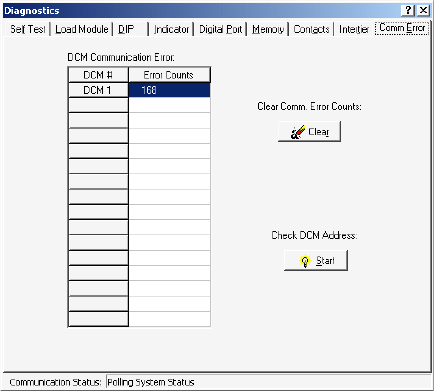
BDS Diagnostics
27-9
Intertier Voltage (mvolts) - This column indicates the voltages being sent. This screen
displays up to 15 intertiers for the BDS and is used to confirm calibration accuracy. The cell
number is the lower of the two cell numbers across which the intertier is connected (selected
on BDS Setup|Battery|Parameters).
27.10. Communication Error (BDS)
String View > Diagnostics|DCM Comm Error
When communication integrity between the BDS and DCM fails, the Error Counts for the
associated DCM increments, and String Status on the String View screen indicates
"DCM-Comm Error." Error Counts can reach 255 before rolling back to zero.
Check DCM Address area - Click Start to check the DCM address. Using groups of flashes,
the DCM Status LED indicates the string and DCM address for that DCM. The first series of
flashes indicates the string ID. (For example, one flash means string 1, five flashes string 5.)
After a pause, a second series of flashes indicates the DCM ID within that string. After
another pause, two rapid flashes indicate the end of the cycle, which then starts over.
Figure 132. Diagnostics - Communication Error (BDS)
Clear Comm Error Counts area - Click Clear to reset the Error Counts values to zero.
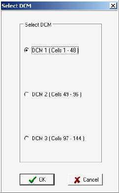
BDS Diagnostics
27-10
27.11. Resistance Testing Multiple DCM Units
String View > Cell Resistance or Intercell Resistance tab > Diagnostics|R-Test in a DCM
A BDS resistance test checks all the DCM units connected to the BDS. To test a specific
DCM, click the Cell Resistance or Intercell Resistance tab then select R-Test in a DCM. On
the Select DCM box, click the button for the DCM you want to test. To capture new readings,
click OK.
Figure 133. Select DCM
If you clicked OK from Cell Resistance, the screen heading changes to Resistance in DCM n
(Cells n - n) (microhms) and the resistance test starts.
If you clicked OK from Intercell Resistance, the heading changes to Intercell in DCM n
(Cells n - n) (microhms) and the resistance test starts.
After a few minutes, 'test in progress' disappears, and the Get button becomes active. Click
Get to display the readings. The bottom of the screen displays a summary of the resistances
and intertier values measured. To stop the test before completion, click Stop.
Diagnostics does not transfer resistance readings to the permanent database. Be certain to
record the needed results before closing these screens.
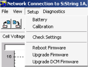
Upgrades
28-1
28. Upgrades
String View > Setup|Upgrade Firmware or Upgrade DCM Firmware
E2 (electrically erasable) memory on the MPM and SRAM memory on the BDS Controller store
calibration, setup information, and actual test data. On both units, flash memory is for uploads of
firmware, which can be upgraded on-site or remotely via modem. Refer to the MPM or BDS
Diagnostics-Memory section for a complete description.
The latest upgrades and upgrade instructions are on the Web at www.alber.com.
NOTE: On the BDS, the Setup|Upgrade Firmware item is enabled only when the BDS Controller
is connected to String 1.
Figure 134. Setup Menu Showing Upgrade Options (BDS)
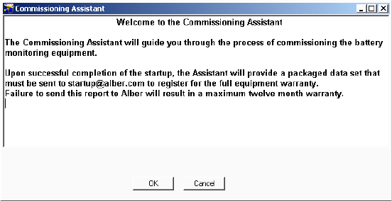
Commissioning Assistant
29-1
29. Commissioning Assistant
View|Reports|Commissioning Report
The Commissioning Assistant creates a report that is extremely helpful if technical support must
be provided for your system. Similar to a setup wizard, the assistant helps you commission a
string by instructing you to perform certain functions and record the results. You may also use the
assistant to exchange equipment and recommission the string. Some assistant screens appear only
if certain equipment or options are selected.
NOTE: Each commissioning assistant screen has complete instructions at the top of the screen.
The instructions in this chapter are only meant to supplement the instructions on the screens. Be
certain to follow the instructions on each screen.
After completing the commissioning assistant, send the saved report with a file name .CMS
extension as an email attachment. Emailing the report to startup@alber.com is mandatory, as the
report is an integral part of the product warranty.
29.1. Starting the Assistant for a New String
Connecting to a string for the first time opens the commissioning assistant Welcome screen.
Figure 135. Commissioning Assistant Welcome
To commission the string, click OK on the Welcome screen to display the MPM or BDS
Monitor Pre-Power Check List. If you click Cancel, the Welcome screen displays until you
acknowledge the Pre-Power Check List or you click the Existing System Ignore button.
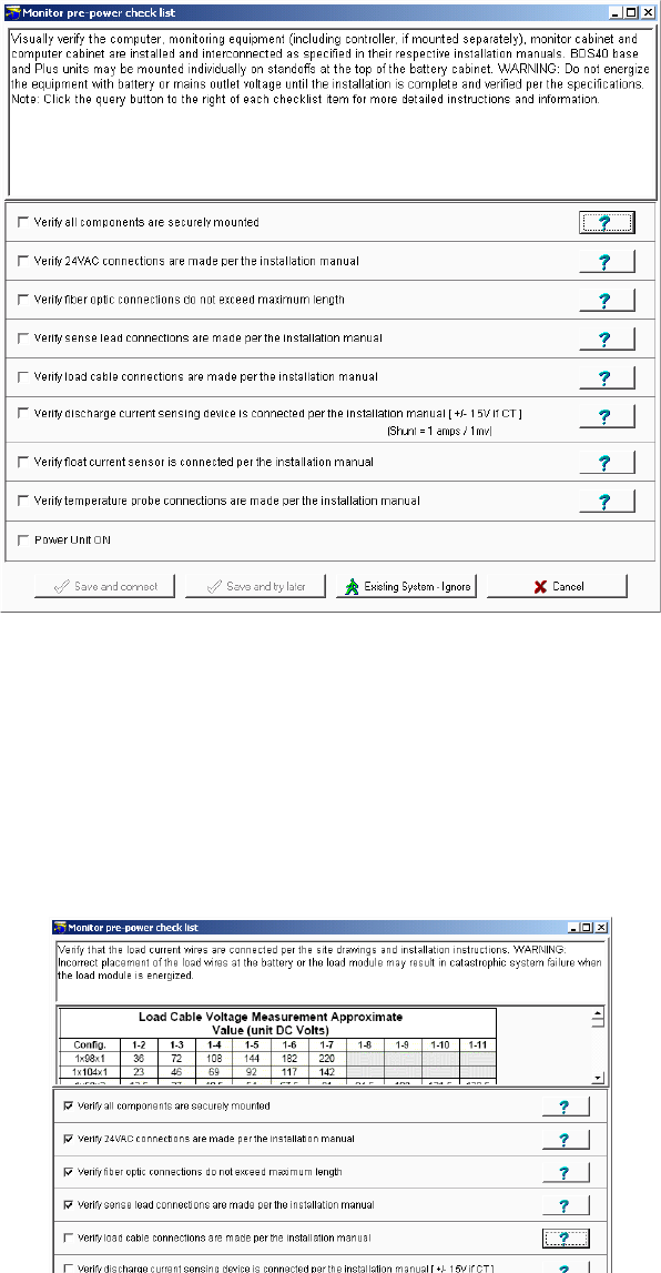
Commissioning Assistant
29-2
29.2. Monitor Pre-Power Check List
Figure 136. Monitor Pre-Power Screen (typical)
The text at the top of the Monitor Pre-Power Check List depends upon the Help (question
mark) button clicked. The screen is similar for the MPM and BDS monitors. As you complete
each item, check the box before the item. When all boxes are checked, connect to the string
by clicking the Save and Connect button. To save a partially completed check list and
connect later, click Save and Try Later.
If the string was previously commissioned, click Existing System - Ignore to connect to the
string. The remaining commissioning assistant screens will not appear.
Figure 137. Monitor Pre-Power Load Cable Help Screen
To display a table that shows the voltages between the load cables for configurations, click
the question mark on the "Verify load cable connections are made…" line.
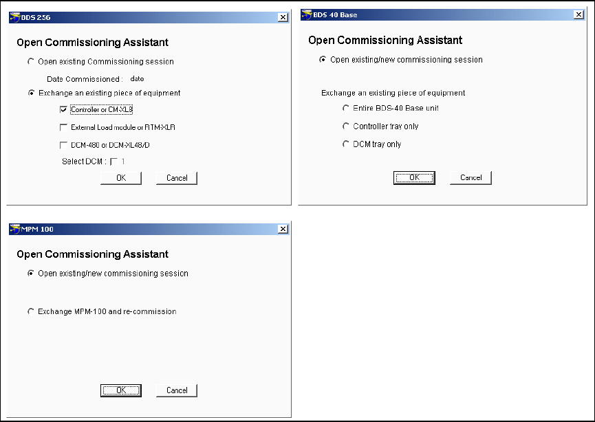
Commissioning Assistant
29-3
29.3. Starting the Assistant for an Existing String
View|Reports|Commissioning Report
This section describes how to start the assistant for a string that is partially or fully
commissioned or for which you want to exchange equipment. To open the assistant, first
connect to the string. On the String View screen, select View|Reports|Commissioning Report
to display one of the Open Commissioning Assistant screens. These screens appear for a
commissioned string or a partially commissioned string if Continue Later was clicked during
a commissioning session.
Figure 138. Open Commissioning Assistant
To continue with a session, click the Open Existing/New Commissioning Session option
button then click OK. If replacing hardware on a previously commissioned string, click the
Exchange Equipment option button, then check a box for the equipment being exchanged.
For units with multiple DCM's, select the appropriate DCM check box. After making
selections, click OK.
One of three MPM or BDS Open
Commissioning Assistant screens
appears. Options on these screens let you
open an existing commissioning session or
exchange a piece of equipment in the
system. Exchanging equipment requires
that the string be commissioned again.
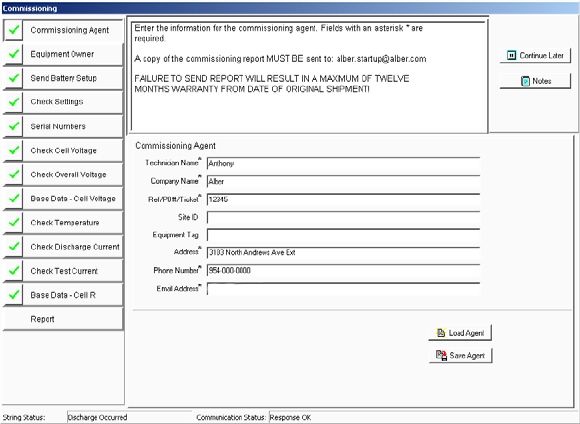
Commissioning Assistant
29-4
29.4. Completing the Commissioning Assistant
After opening the commissioning assistant, complete the remaining screens as described in
the following sections.
29.4.1. Commissioning Agent Screen
Figure 139. Commissioning Agent (Comm Asst)
Click the Commissioning Agent button. Complete the following fields: Technician Name,
Company Name, Reference/PO No./Ticket No., Site ID, Equipment Tag, Address,
Phone Number, and Email Address. Note that fields for which information is mandatory are
marked with an ( * ) asterisk.
To save the technician name, company name, address, telephone number, and email address
for future commissioning reports, click Save Agent. To place previously saved agent data into
these fields, click Load Agent. You may save only one set of agent data.
To add a note to the report, click the Notes button, type the text into the Agent Notes dialog
box, then close the box. The text will appear in the Agent Notes section in the report. The
Notes button on the other screens accesses this same Agent Notes dialog box.
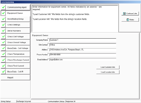
Commissioning Assistant
29-5
29.4.2. Equipment Owner Screen
Figure 140. Equipment Owner (Comm Asst)
Click the Equipment Owner button. Complete the following fields: Company Name,
Site Contact, Address, Phone Number, and Email Address. Note that fields for which
information is mandatory are marked with an ( * ) asterisk. Optionally, to load the data saved
under Setup|System|Customer or under Setup|System|Location into the fields, click the
Load Customer Info or Load Location Info buttons.
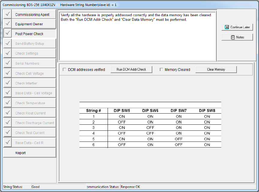
Commissioning Assistant
29-6
29.4.3. Post Power Check Screen
Figure 141. Post Power Check Screen (BDS-256 only) (Comm Asst)
Click the Post Power Check button. Verify the DCM addresses by clicking “Run DCM
Addr Check” button then, at the “Running DCM Address Check” message click Yes to check
all DCM addresses. Also, clear the data memory by clicking the “Clear Memory” button then,
at the "Clear Monitor Memory" message click Yes and the memory is cleared. After
verification, the DCM Addresses Verified box is automatically checked.
Note: The MPM does not have dip switch settings.
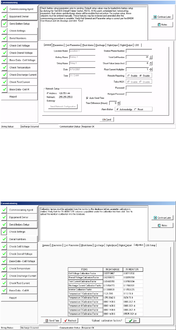
Commissioning Assistant
29-7
29.4.4. Send Battery Setup Screen
Figure 142. Send Battery Setup (Comm Asst)
Click the Send Battery Setup button. Verify the values displayed on the screen, make
changes if necessary, then click Send to transfer the settings to the monitor. Note that event
recording is ignored and the system doesn't alarm during commissioning. Alarms are disabled
until the base resistance thresholds are sent. If using string current for discharge detection, the
minimum value that can be entered is 5 percent of the shunt value.
29.4.5. Check Settings Screen
Figure 143. Check Settings (Comm Asst)
Click the Check Settings button. Confirm the values, then click Yes to upload the
calibration constants from the monitor to the database. If you click Recheck, the screen
refreshes. NOTE: Only the calibration constants are uploaded.
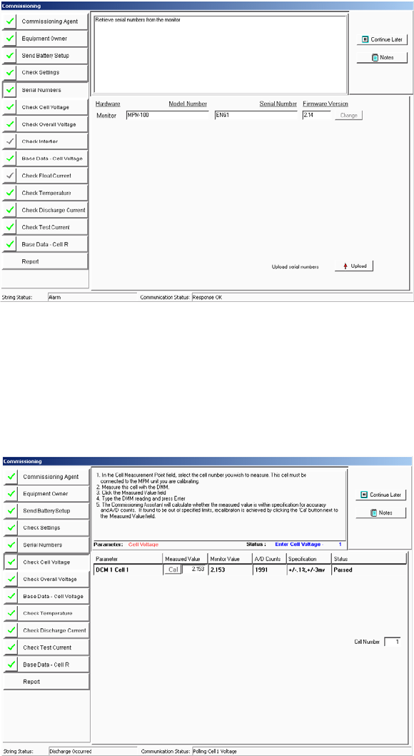
Commissioning Assistant
29-8
29.4.6. Serial Numbers Screen
Figure 144. Serial Numbers (Comm Asst)
Click the Serial Numbers button. To upload the serial numbers and firmware revisions
from the connected hardware, click the Upload button. If the data is incorrect, click in the
field to type the correct data and click the Change button to send the data to the hardware.
The RTM and ELM serial numbers must be typed in manually.
29.4.7. Check Cell Voltage Screen
Figure 145. Check Cell Voltage (Comm Asst)
Click the Check Cell Voltage button. Measure the voltage across the cell indicated, type the
value in the Measured Value field, then press <Enter>. If the measured value agrees with the
calculated value in the monitor, the Status area indicates Passed. If it fails, calibrate the
monitor to the measured value by clicking the Cal button. Note that, if there is a more
convenient cell to measure, you may change the Cell Number to any cell within the DCM.
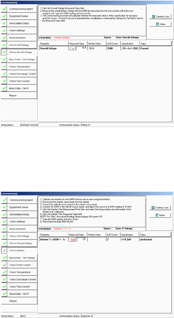
Commissioning Assistant
29-9
29.4.8. Check Overall Voltage Screen
Figure 146. Check Overall Voltage (Comm Asst)
Click the Check Overall Voltage button. (Not used with BDS-40.) Measure the overall
voltage, type the value in the Measured Value field, then press <Enter>. If the measured
value agrees with the calculated value in the monitor, the Status area indicates Passed. If the
measured value fails, calibrate the monitor to the measured value by clicking the Cal button.
29.4.9. Check Intertier Screen
Figure 147. Check Intertier (Comm Asst)
Click the Check Intertier button. Measure the intertier voltage, type the value in the
Measured Value field, then press <Enter>. If the measured value agrees with the calculated
value in the monitor, the Status area indicates Passed. The list dynamically changes to show
all intertiers and charger cables. You only have to verify one intertier per DCM. If the
measured value fails, calibrate the monitor to the measured value by clicking the Cal button.
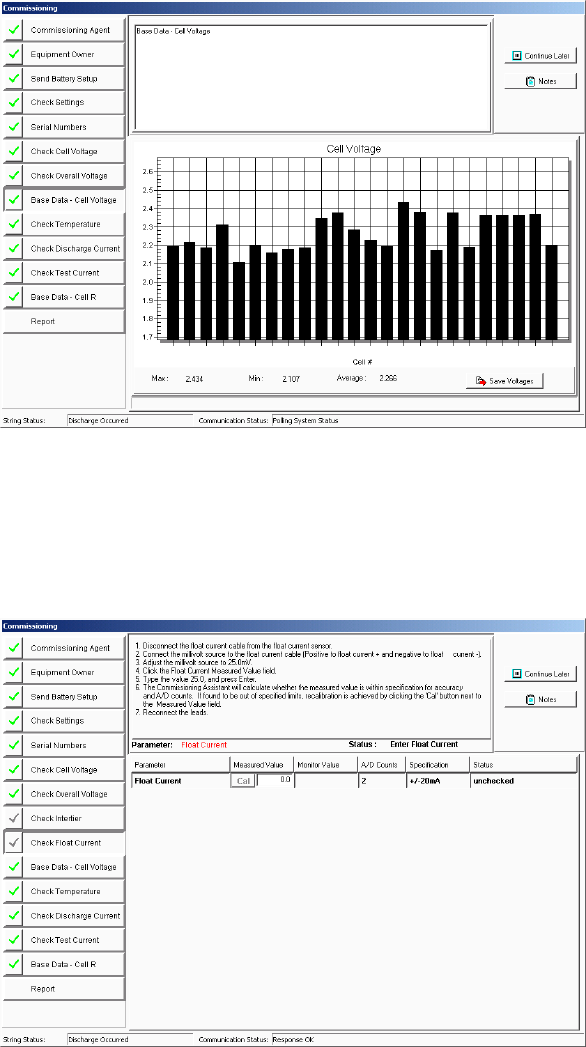
Commissioning Assistant
29-10
29.4.10. Base Data - Cell Voltage Screen
Figure 148. Base Data - Cell Voltage (Comm Asst)
Click the Base Data - Cell Voltage button. Data on this screen readily identifies wiring
problems. To save the data, click the Save Voltages button. The voltage data is saved as the
baseline float voltage readings, and the baseline voltages appear in the commissioning report.
29.4.11. Check Float Current Screen
Figure 149. Check Float Current (Comm Asst)
Click the Check Float Current button. Type the float current value in the Measured Value
field, then press <Enter>. If the measured value agrees with the calculated value in the
monitor, the Status area indicates Passed. If the measured value fails, calibrate the monitor to
the measured value by clicking the Cal button.
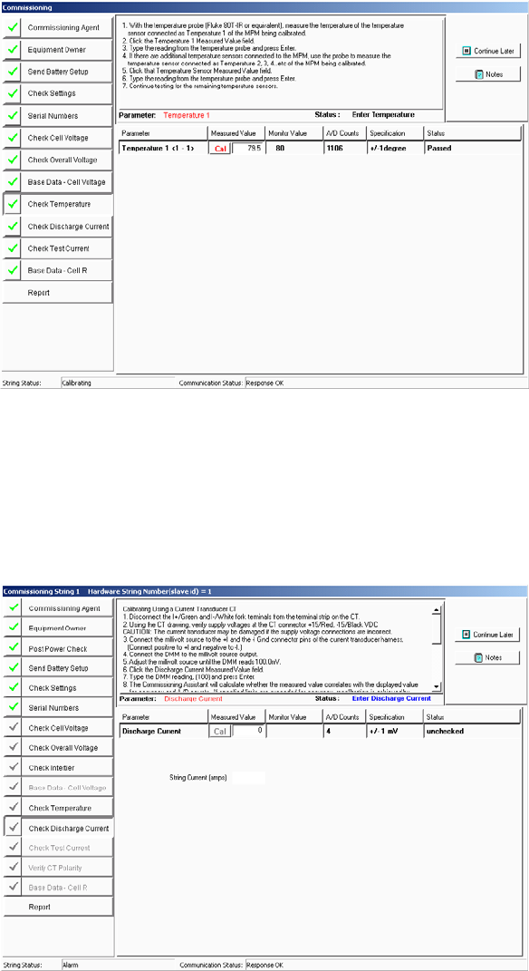
Commissioning Assistant
29-11
29.4.12. Check Temperature Screen
Figure 150. Check Temperature (Comm Asst)
Click the Check Temperature button. Type the ambient temperature value in the
Measured Value field. If the measured value agrees with the calculated value in the monitor,
the Status area indicates Passed. If the measured value fails, calibrate the monitor to the
measured value by clicking the Cal button.
29.4.13. Check Discharge Current Screen
Figure 151. Check Discharge Current (Comm Asst)
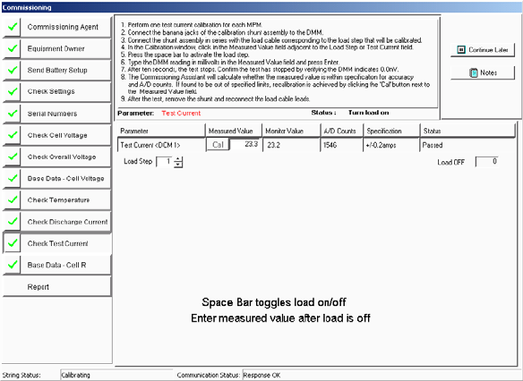
Commissioning Assistant
29-12
Click the Check Discharge Current button. Verify the ±15VDC voltage supply is
connected to the current transducer. Type the discharge current value in the Measured Value
field. The String Current (amps) field displays the millivolt value times the shunt value as
amps. If the measured value agrees with the calculated value in the monitor, the Status area
indicates Passed. If the measured value fails, calibrate the monitor to the measured value by
clicking the Cal button.
29.4.14. Check Test Current Screen
Figure 152. Check Test Current (Comm Asst)
Click the Check Test Current button. Before running this test, verify that all the voltages
across the load wires are correct. Failure to do this may result in severe damage to the load
module.
Select a load step from the Load Step spin box. Press the <Space Bar> to turn on the load,
and measure the load current. Type the value in the Measured Value field, then press
<Enter>. If the measured value agrees with the calculated value in the monitor, the Status
area indicates Passed. If the measured value fails, calibrate the monitor to the measured value
by clicking the Cal button.
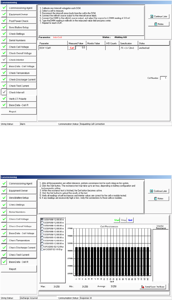
Commissioning Assistant
29-13
29.4.15. Check Intercell Screen (BDS Only)
Figure 153. Check Intercell (Comm Asst)
Click the Check Intercell button. In the Cell Number box, type the cell number for the cell
you wish to measure. This is only for dual reading systems, such as the BDS-256XL.
29.4.16. Base Data - Cell Resistance Screen
Figure 154. Base Data - Cell Resistance (Comm Asst)
Click the Base Data Cell R button. If necessary, click the Start button to perform a
resistance test. Then, check a box in the left column to select a test that will be used to
establish alarm levels and be stored as baseline data. Click the Send/Save/Thr/Base button.
On the next screen, accept the defaults or make changes if required, then click OK.
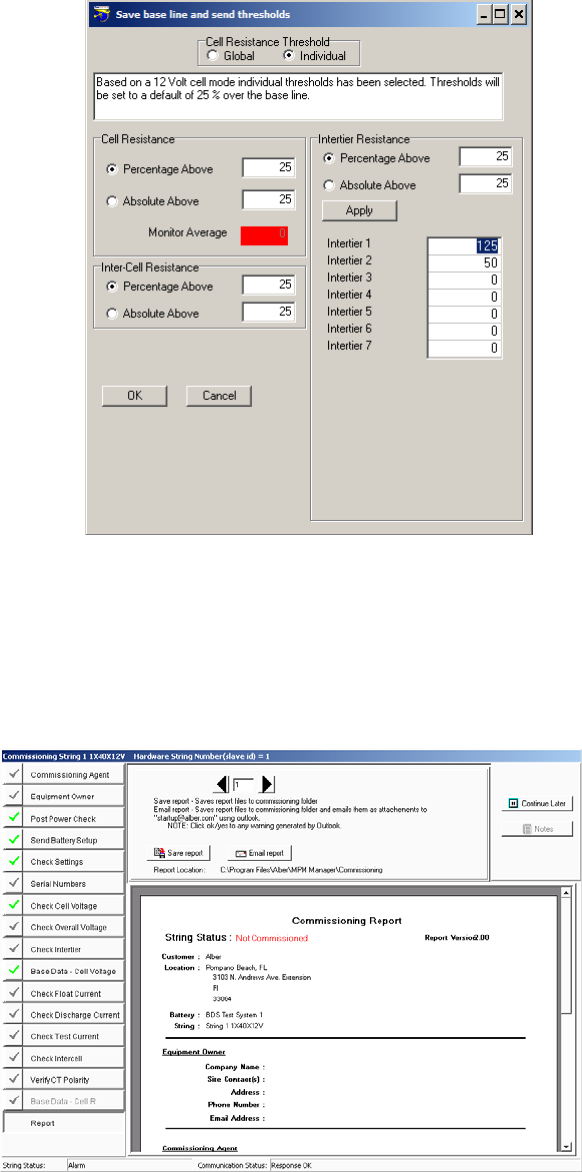
Commissioning Assistant
29-14
Figure 155. Save Base Line and Send Thresholds Data – Cell/Intertier/Inter-Cell Resistance (Comm
Asst)
Based on a 12 volt cell mode, individual threshholds have been selected.
Note: Thresholds will be set to a default of 25 percent over the base line.
When making changes to the Intertiers, click Apply to save the updated values.
29.4.17. Report Screen
Figure 156. Report (Comm Asst)
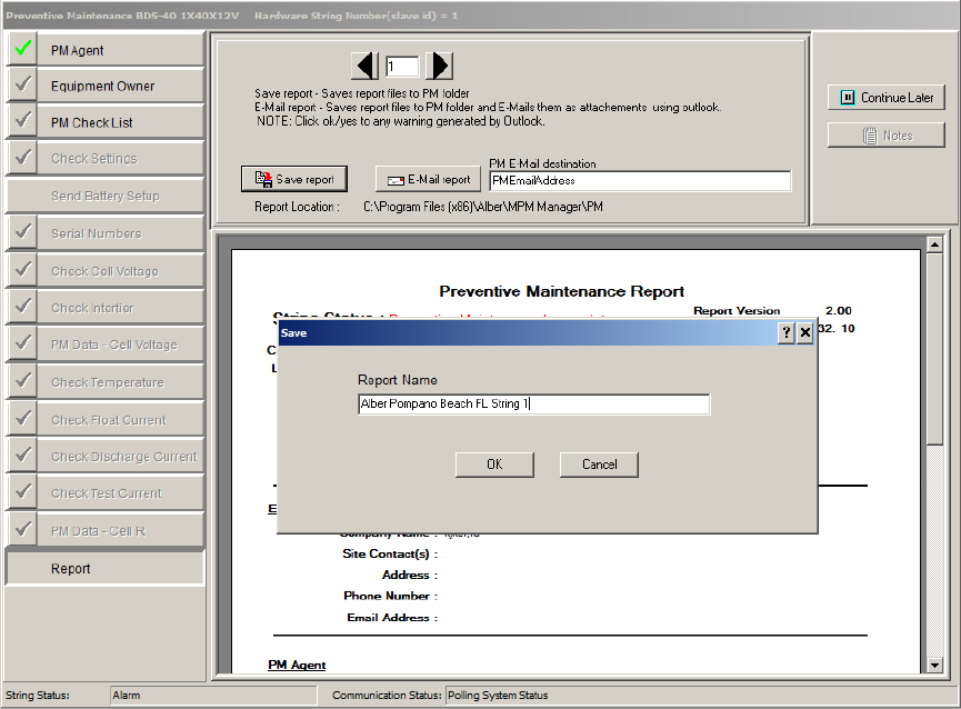
Commissioning Assistant
29-15
Click the Report button. Text on the screen displays the path and folder where the report is
saved. To view pages in the report, click the left or right arrows. To save the report as a CMS
file in the Commissioning folder, click Save Report. To save and email the report to Alber,
click the Email Report button. The CMS file is password protected and cannot be opened.
29.4.18. Preventive Maintenance Report Form
Figure 157. Report (Preventive Maintenance) Form
The Preventive Maintenance Report saves customer data by default in the following fields:
• Equipment Owner name
• Site ID
• Ref PO # Ticket
• Equipment Tag
The field names can be modified on the form. The modified field names from the form will
show the new names in the report name.
Once the new field names are entered, click Save Report.
Click OK to save the new preventive maintenance report.
Commissioning Assistant
29-16
29.5. Emailing a Report
The completed Commissioning Agent report must be sent to Alber as an email attachment for
warranty and customer service purposes. To send the report, open your email editor and
attach the report CMS file to the email. The CMS file resides in the Program Files\
Alber\MPM Manager\Commissioning folder. In the subject line, type "BMDM
commissioning report" or similar text. In the email, note your company name and contact
information. Send the email with the CMS file to startup@alber.com.
29.6. Retrieving a Commissioning Report
View|Reports|Commissioning Report
To view a report, connect to the string then click View|Reports|Commissioning Report on the
Main Menu. Do not edit completed report screens unless the string is being commissioned
again.
29.7. Printing a Commissioning Report
The completed CMS report file cannot be printed. However, there are two printing options.
A PDF file stored in the same Commissioning folder as the CMS file can be printed as a one
page document. This summary report is immediately accessible upon partial or full
commissioning of a string. The file name starts with CAR and ends with PDF. The printed
page can serve as confirmation that the string was commissioned.
After Alber receives a complete CMS commissioning file, Alber generates a PDF file of the
report and emails it back to the originator. This PDF file, which may be printed, is a
multipage document that details the commissioning of the system.

Error Codes
30-1
30. Error Codes
The following error messages may appear when running the BMDM program.
CODE
MESSAGE
SITUATION
1
The database cannot be saved. Hard drive could be
full.
When copying a database to
a working database
2
Empty database not found.
When backing up a database
5
Database Not Found. <Database File Name>
When opening a database
6
Data import error (DDetail Table). Please try again.
When importing discharge
data
7
Data import error (DSummary Table). Please try
again.
When importing discharge
data
100
The name chosen has already been used. It must be
unique.
The user set up two locations
using the same name or ID
101
There are more than 1000 strings.
In the local computer, there
are more than 16 locations
set up.
102
Location name, battery name and string name do not
match.
Actual location name is <LocationName>. Actual
battery name is <BatteryName>.
Actual string name is <StringName>.
In direct connection,
compare location ID in
monitor and in database
103
SERVICE cannot be deleted.
The user tries to delete
Service location
104
Invalid name.
Input invalid location name
in location setup
105
String not found in <Database table name>.
Search location
106
String ID not found in <Database table name>.
Search location
107
The telephone number of string <StringName> is not
set.
108
The pager number of string <StringName>is not set.
109
Number of strings or configuration is not set properly.
110
You have to setup customer info before setup location
info.
111
You have to setup location info before setup battery
info.
112
You have to setup battery info before setup string
info.
113
Location name, battery name and string name do not
exist. Location name is <LocationName>. Battery
name is <BatteryName>. String name is
<StringName>.
114
Invalid input.
115
The number of data set is <SetNum>. More than one
data set must exist before a trending analysis can be
performed.
116
Invalid IP address.
117
Invalid netmask address.
118
Invalid gateway address.
200
No response on Polling/Answer Port Modem.
When initializing modem
201
No response on Answer Port Modem.
When initializing modem
202
The currently selected COM Port, COM
<ComPortNum>, does not exist. Press OK and choose
a different port.
When initializing COM port

Error Codes
30-2
CODE
MESSAGE
SITUATION
203
The currently selected COM Port, COM
<ComPortNum>, is already in use by another
program. Press OK and choose a different port.
When initializing COM port
204
The currently selected Com Port, Com
<ComPortNum>, is not available. Press OK and
choose a different port.
When initializing COM port
205
No response from Modem/Cable Multiplexer.
When connecting
modem/cable multiplexer
206
Comm Error: No response for sending "Stop Scan"
command 3 times.
207
Comm Error: No response for sending "Start Scan"
command 3 times.
208
Comm Error: No response for sending "Load Off"
command 3 times.
209
Comm Error: No response for sending "Send DCM #"
command 3 times.
300
Upgrade failed: No response for sending code 3 times.
When sending frames
301
Upgrade failed: Not responding.
Check firmware location
(PROM or flush memory) in
the beginning of firmware
upgrade
302
Upgrade failed: Code confirm failed.
400
Resistance test failed: 60 minute time-out.
Manual R-test is not
completed in 60 minutes
401
Data format error. The data may be saved for a
different MPM configuration.
When reading resistance or
historical data
402
The raw count equals 0. Please check hardware.
During calibration
403
Data import error (Encode date/time). Please try
again.
When importing alarm data
404
Wrong overall voltage data.
Got invalid overall voltage in
discharge data
405
Subset <SubsetNum> does not have an initial value.
When viewing discharge
curves, found invalid subset
406
Subset <SubsetNum> does not have a final value.
When viewing discharge
curves, found invalid subset
407
Discharge data cannot be shown due to invalid
Date/Time.
500
Subset 3 is selected, but Subset 2 is not selected. If
you want to show two curves, the second curve
should be in Subset 2.
Wrong selection in Curve
Option of Discharge View
screen
501
Two password entries are not identical. Please enter
again.
502
Password must have five characters.
1000
The string name exists. It must be unique.
1001
The battery name exists. It must be unique.
1002
The location name exists. It must be unique.
1003
The customer name exists. It must be unique.
Index
% above baseline field
on detail cell resistance s/u .................. 22-3
on trend cell resistance s/u ................... 22-6
24/7 on contact information ................... 14-13
a/d counts column on calibration ............. 25-2
a/d status
on self test diagnostics BDS ................ 27-1
on self test diagnostics MPM ............... 26-2
absolute above button
on cell resistance alarm levels BDS . 18-11
on cell resistance alarm levels MPM ... 17-7
absolute date and time button
on battery s/u test parameters BDS .... 18-9
on battery s/u test parameters MPM ... 17-5
Access
creating a database ................................. 4-4
database backup ............................ 7-2, 21-1
database on BMDM ................................... 4-1
deleting a database ................................. 4-4
access telephone number field
on contact information ........................ 14-13
on system s/u reporting ......................... 14-9
account field on email s/u ......................... 13-1
acknowledge
a. alarm button on current alarm ...... 21-15
a. alarm menu item ....................21-4, 21-15
a. button
on battery s/u general BDS .............. 18-3
on battery s/u general MPM ............. 17-3
active ck box on contact information .... 14-12
ACV@30 column
on all discharges ................................. 21-16
on discharge s/u .................................. 22-11
alarm
a. button
on indicator diagnostics MPM .......... 26-5
a. button area
on battery s/u general BDS .............. 18-3
on battery s/u general MPM ............. 17-3
a. date area
on historical alarm selection .......... 21-14
a. detail column on historical events ... 21-6
a. disable button
on indicator diagnostics MPM .......... 26-5
a. event boxes ........................................ 21-4
a. reset button on MPM/BDS ............ 21-15
a. reset switch on BDS .......................... 15-2
a. reset switch on MPM ......................... 15-2
a. setup screen .................................. 22-11
a. type area
on alarms s/u ................................... 22-11
on historical alarm selection .......... 21-14
acknowledge ...............................21-4, 21-15
data ......................................................... 21-12
deleting from database ....................... 21-14
records ............................................... 9-1, 9-2
setup ....................................................... 22-11
thresholds
on battery s/u float alarms BDS .... 18-11
on battery s/u float alarms MPM ......17-7
alarm threshold count box
on preferences........................................11-2
AlberDemo.mdb file ..................................... 4-1
all available button
on system s/u reporting ...................... 14-10
all button on system s/u reporting......... 14-10
all dates button
on historical alarm selection .............. 21-14
all discharge ............................................. 21-15
all discharge screen ............................. 21-15
all types button
on historical alarm selection .............. 21-14
alpha button
on contact information ........................ 14-13
on system s/u reporting .........................14-9
alternate field title field on preferences ...11-2
always contact ck box
on contact information ........................ 14-12
amp hours
amp hours field
on battery s/u discharge BDS ....... 18-17
on battery s/u discharge MPM ...... 17-10
with Peukert's equation .........................10-1
amps per millivolt
on battery s/u general BDS ..................18-2
on battery s/u general MPM .................17-2
answer port area on comm s/u ................12-1
apply button
on cell resistance alarm levels BDS . 18-11
on cell resistance alarm levels MPM ...17-7
archive reader .............................................23-2
archive report ..............................................23-2
authentication ck box
on email s/u .............................................13-1
auto extract data ck box
on communication s/u ...........................12-2
auto generating tech detail summary
screen .....................................................24-3
auto include all data sets ck box
on detail cell voltage s/u ........................22-2
auto select cells ck box
on trend cell voltage s/u ........................22-5
auto select ck box
on all discharges ................................. 21-16
on discharge s/u .................................. 22-10
auto send time ck box

on battery s/u general BDS .................. 18-3
on battery s/u general MPM ................. 17-3
autopolling ....................................... See polling
average button
on battery s/u test parameters BDS . 18-10
on battery s/u test parameters MPM ... 17-6
average cell resistance field
on battery s/u test parameters BDS . 18-10
backup
b.u. database button .............................. 21-1
defined ....................................................... 7-2
of Access database ....................... 7-2, 21-1
base data cell resistance in comm asst 29-13
base data cell voltage in comm asst .... 29-10
baseline field
on detail cell resistance s/u .................. 22-3
on trend cell resistance s/u ................... 22-6
battery
b button on preferences ........................ 11-2
b. capacity field
on system s/u battery ........................ 14-4
b. name column on string status .......... 21-2
b. name field
on battery s/u general BDS .............. 18-2
on battery s/u general MPM ............. 17-2
on system s/u battery ........................ 14-4
b. status viewing ....................................... 21-1
b. system s/u ............................................. 14-4
b. system setup screen ...................... 14-4
changing name ....................................... 14-1
locations connection ................................ 20-1
setup
digital input BDS ............................... 18-18
digital input MPM ............................. 17-11
digital input screen BDS ............. 18-18
digital input screen MPM ............ 17-11
digital output BDS ............................. 18-19
digital output MPM ........................... 17-12
digital output screen BDS .......... 18-19
digital output screen MPM ......... 17-12
discharge BDS ................................... 18-16
discharge MPM.................................... 17-9
discharge screen BDS ................. 18-16
discharge screen MPM ................... 17-9
float alarms BDS ............................... 18-10
float alarms MPM ................................ 17-6
float alarms screen BDS ............. 18-10
float alarms screen MPM ............... 17-6
general BDS ......................................... 18-2
general MPM ....................................... 17-2
general screen BDS ........................ 18-2
general screen MPM ....................... 17-2
LGS BDS ............................................ 18-20
LGS MPM .......................................... 17-13
LGS screen BDS ........................... 18-20
LGS screen MPM .......................... 17-13
parameters BDS ................................... 18-4
parameters MPM ................................. 17-4
parameters screen BDS .................18-4
parameters screen MPM ................17-4
test parameters BDS ............................ 18-9
test parameters MPM ........................... 17-5
test parameters screen BDS .........18-9
test parameters screen MPM ........17-5
thermal runaway BDS......................... 18-14
thermal runaway screen BDS .... 18-14
setup for the BDS ..................................... 18-1
setup for the MPM ................................... 17-1
status viewing ........................................... 21-1
battery setup
password ................................................... 4-4
black bar graph ...........................................21-7
BMDM
installing the program ............................... 4-1
new system s/u .......................................... 14-1
BMDM opening screen ............................. 4-1
calibration ....................................................25-1
c. (BDS) check settings screen ........16-9
c. (BDS) screen .....................................25-1
c. (MPM) check settings screen .......16-9
c. (MPM) screen ....................................25-1
c. check settings .....................................16-9
c. factor column on calibration .............25-2
call all modem strings button ....................21-4
capture readings ........................................21-9
cell
c. detail area
on all discharges ............................. 21-17
on discharge s/u .............................. 22-11
c. detail ck box
on all discharges ............................. 21-16
on discharge s/u .............................. 22-11
c. graph ck box
on all discharges ............................. 21-16
on discharge s/u .............................. 22-11
c. manufacturer field
on system s/u string ...........................14-7
c. memo .................................................. 21-22
c. memo menu item ............................ 21-22
c. memo screen ................................. 21-22
c. memos ck box on discharge s/u ... 22-10
c. model field on system s/u string ......14-7
c. resistance .............................................. 21-8
c. resistance screen ............................21-8
c. resistance tab on string view .. 21-8, 21-9
c. voltage ................................................... 21-7
c. voltage box..................................... 21-11
c. voltage box on string view .................. 21-11
c. voltage button on curve option ...... 21-20
c. voltage field
on battery s/u parameters BDS........18-8
c. voltage screen ..................................21-7

cell # column
on battery s/u parameters BDS ............. 18-8
cell # field
on battery s/u parameters MPM ...... 17-4
cell # label start from area
on system s/u battery ........................ 14-5
phone for messages ........................... 14-11
trend analysis ...................................... 21-11
cell column
on cell resistance alarm levels BDS . 18-11
on cell resistance alarm levels MPM ... 17-7
cell resistance alarm levels box
BDS ....................................................... 18-11
MPM ......................................................... 17-7
cell resistance alarm levels screen
BDS ...................................................... 18-11
MPM ......................................................... 17-7
cell resistance threshold area
on battery s/u float alarms BDS ........ 18-11
on battery s/u float alarms MPM .......... 17-6
cells
c. below threshold area on summary 21-21
c. column on battery s/u parameters BDS
.............................................................. 18-4
central computer
button on select computer type .............. 4-5
changing to ................................................ 4-6
connection steps ......................................... 8-2
defined ........................................................ 6-1
defining ...................................................... 4-5
extracting data .......................................... 7-2
polling ........................................................ 7-2
change elapsed time slider .................... 21-18
change time slider ................................... 21-19
changing computer type ................................ 4-6
changing names or info ............................. 14-1
charger control button
on contacts diagnostics MPM .............. 26-7
charger ripple frequency
on battery s/u general BDS .................. 18-2
check cell voltage in comm asst .............. 29-8
check DCM address button
on comm error diagnostics BDS .......... 27-9
check discharge current in comm asst 29-12
check float current in comm asst .......... 29-10
check intertier in comm asst ..................... 29-9
check overall voltage in comm asst ........ 29-9
check settings
and synchronizing.................................... 15-1
c.s. in controller ..................................... 16-11
c.s. in controller screens ................ 16-11
calibration ................................................ 16-9
calibration (BDS) screen .................... 16-9
calibration (MPM) screen ................... 16-9
digital input .............................................. 16-7
digital input (BDS) screen ................. 16-7
digital input (MPM) screen .................16-7
digital output ...........................................16-8
digital output (BDS) screen ...................... 16-8
discharge .................................................16-6
discharge screen .................................16-6
float alarms .............................................16-4
float alarms (BDS) screen ........ 16-4, 16-5
float alarms (MPM) screen .................16-4
general .....................................................16-1
general screen ......................................16-1
LGS screen ......................................... 16-10
parameters ..............................................16-2
parameters (BDS) screen ...................16-2
parameters (MPM) screen ..................16-2
screens ...................................................... 16-1
test parameters ......................................16-3
test parameters screen.......................16-3
check settings in comm asst ....................29-7
check temperature in comm asst .......... 29-11
check test current in comm asst 29-12, 29-13
clear comm error counts button
on comm error diagnostics BDS ..........27-9
clear counters button
on self test diagnostics BDS .................27-2
clear data memory button ......................... 27-7
on memory diagnostics BDS ................27-7
on memory diagnostics MPM ...............26-6
clear existing names ..................................15-2
CMS file ........................................ 29-15, 29-16
code space
on self test diagnostics BDS .................27-1
column sorting .................................. 21-3, 21-5
com port field on communication s/u ......12-1
commissioning agent screen ....................29-4
commissioning assistant .............................. 29-1
emailing a report ................................. 29-16
open comm assistant screens..............29-3
pre-power check list ...............................29-2
printing a report ................................... 29-16
save and connect button .......................29-2
welcome screen .....................................29-1
communication
c. error diagnostics screen ...............27-9
c. setup screen .....................................12-1
error diagnostics ...................................... 27-9
setup ......................................................... 12-1
computer types ............................................. 4-5
central......................................................... 6-1
changing ..................................................... 4-6
local ............................................................ 6-2
service ......................................................... 6-3
config3.mpm file ........................................... 4-6
configuration wizard ...................................... 5-5
configure station ............................................ 5-1
connection button
for the BDS .............................................18-1

for the MPM ............................................ 17-1
modem to a location .............................. 20-1
network to a location ............................. 20-1
RS-232 to a location .............................. 20-1
contact
c. ck box on system s/u reporting ..... 14-10
c. field on system s/u reporting ......... 14-10
c. information ....................................... 14-12
c. information screen ....................... 14-12
contact list
adding names ...................................... 14-14
c.l. ck box on system s/u reporting ... 14-10
c.l. field on system s/u contact list .... 14-11
c.l. field on system s/u reporting ....... 14-10
c.l. mode area on system s/u reporting 14-
10
c.l. system s/u ......................................... 14-11
c.l. system setup screen ................. 14-11
contact n button
on contacts diagnostics BDS ............... 27-8
contacts area on system s/u contact list ... 14-
12
contacts diagnostics
for the BDS .............................................. 27-8
for the BDS screen .............................. 27-8
for the MPM ............................................ 26-7
for the MPM screen ............................. 26-7
continuous polling ........................................ 7-2
continuous polling interval field
on communication s/u ........................... 12-2
control output contact ................. 17-12, 18-19
critical alarm button
on contacts diagnostics BDS ............... 27-8
on indicator diagnostics BDS ............... 27-6
critical alarm ck box
on battery s/u discharge BDS ........... 18-16
critical ck box
on battery s/u digital input BDS ........ 18-18
on battery s/u float alarms BDS ........ 18-13
cumulative time column
on executive summary report ............... 24-2
current 1 to 4 check boxes .................... 21-16
current alarm ........................................... 21-13
current alarm screen............................ 21-13
current mode button
on battery s/u discharge BDS ........... 18-16
on battery s/u discharge MPM ............. 17-9
curve n area ............................................. 21-20
curve option ............................................. 21-19
curve option screen ............................. 21-20
customer
adding ...................................................... 14-1
c. button on preferences ....................... 11-2
c. contact area
on system s/u customer .................... 14-2
c. contact ck box
on system s/u reporting .................. 14-10
c. field on system s/u location ..............14-3
c. name column on string status ..........21-2
c. name field
on system s/u customer ....................14-2
c. status viewing ....................................... 21-1
c. system s/u .............................................. 14-2
c. system setup screen ......................14-2
data defined .................................................. 7-1
data extraction defined ................................ 7-1
data point value ....................................... 21-12
data set defined ..........................................22-1
data sets area
on detail cell voltage s/u ........................22-2
on trend cell voltage s/u ........................22-6
database
automatic updating on install .................. 4-5
backup of Access file ..................... 7-2, 21-1
d range, selecting ..................................... 19-1
d. file, creating a new Access ................. 4-4
deleting for Access .................................. 4-4
opening a database .................................. 21-1
saving a database ..................................... 21-1
date and time fields
on battery s/u general BDS ..................18-2
on battery s/u general MPM .................17-2
date format ..................................................14-4
date, sending using check setting ...........16-1
day interval button
on battery s/u test parameters BDS ....18-9
on battery s/u test parameters MPM ...17-5
day off ck box
on contact information ........................ 14-13
DC (discharge current) on DCM
on battery s/u parameters BDS............18-8
DCM # arrows
on load module diagnostics BDS .........27-3
DCM addresses verified check box .............. 29-6
DCM communication error area
on comm error diagnostics BDS ..........27-9
DCM n (Cells n - n) button ..................... 27-10
default database ............................................. 4-4
default password ............................................ 4-4
default status view on preferences ..........11-2
delay field
on contact information ........................ 14-13
on system s/u reporting ...................... 14-10
delete button
on contact list s/u ................................ 14-11
on system s/u..........................................14-1
detail cell resistance s/u ............................... 22-3
detail cell resistance setup screen......22-3
detail cell voltage s/u .................................... 22-1
detail cell voltage s/u screen ................22-1
detail executive report enable ck box
on preferences........................................11-2
detail intercell resistance s/u ....................... 22-4
deviation storage thresholds area
on battery s/u discharge MPM .......... 17-10
diagnostics
BDS diagnostics ....................................... 27-1
communication error ............................... 27-9
communication error screen ............ 27-9
contacts BDS ............................................ 27-8
contacts BDS screen .......................... 27-8
contacts MPM .......................................... 26-7
contacts MPM screen ......................... 26-7
digital port BDS ....................................... 27-6
digital port BDS screen ...................... 27-6
digital port MPM ..................................... 26-5
digital port MPM screen ..................... 26-5
DIP switch BDS ....................................... 27-5
DIP switch BDS screen ...................... 27-5
DIP switch MPM ..................................... 26-4
DIP switch MPM screen...................... 26-4
indicator MPM ............................... 26-5, 27-6
indicator MPM screen ............... 26-5, 27-6
intertier BDS ............................................ 27-8
intertier BDS screen ............................ 27-8
intertier MPM .......................................... 26-8
intertier MPM screen ........................... 26-8
load module BDS ..................................... 27-3
load module BDS screen ......... 27-3, 27-4
load module MPM ................................... 26-3
load module MPM screen .................. 26-3
memory BDS ............................................ 27-7
memory BDS screen ........................... 27-7
memory MPM .......................................... 26-6
memory MPM screen .......................... 26-6
MPM diagnostics ..................................... 26-1
power up BDS .......................................... 27-1
power up MPM ........................................ 26-1
R-test in a DCM ..................................... 27-10
self test BDS ............................................. 27-1
self test BDS screen ........................... 27-1
self test MPM ........................................... 26-2
self test MPM screen ........................... 26-2
dial prefix field on comm s/u ..................... 12-1
dial tone status
on self test diagnostics BDS ................ 27-2
on self test diagnostics MPM ............... 26-2
digital input
battery s/u BDS ...................................... 18-18
battery s/u MPM .................................... 17-11
battery s/u screen BDS ................... 18-18
battery s/u screen MPM................... 17-11
check settings ......................................... 16-7
check settings screen BDS ............... 16-7
check settings screen MPM .............. 16-7
digital output
battery s/u BDS ...................................... 18-19
battery s/u MPM .................................... 17-12
battery s/u screen BDS .................... 18-19
battery s/u screen MPM ................... 17-12
check settings .........................................16-8
check settings screen BDS ........................ 16-8
digital port
diagnostics BDS ....................................... 27-6
diagnostics BDS screen .....................27-6
diagnostics MPM ..................................... 26-5
diagnostics MPM screen ....................26-5
DIP switch
diagnostics BDS ....................................... 27-5
diagnostics BDS screen .....................27-5
diagnostics MPM ..................................... 26-4
diagnostics MPM screen ....................26-4
direct button on system s/u link ...............14-7
direct connection area
on communication s/u .......................12-1
disable
d. alarm reporting ck box on preferences
..............................................................11-2
d. alarm reporting note ..........................21-6
d. auto polling/answering ck box
on communication s/u .......................12-2
d. button
on battery s/u discharge BDS ....... 18-17
on battery s/u discharge MPM ...... 17-10
d. email ck box on email s/u .................13-1
d. sound ck box on preferences ...........11-2
discharge
battery s/u BDS ...................................... 18-16
battery s/u MPM ...................................... 17-9
battery s/u screen BDS .................... 18-16
battery s/u screen MPM ......................17-9
check settings .........................................16-6
check settings screen.........................16-6
d. current area
on battery s/u parameters MPM ......17-4
d. current button on curve option ...... 21-20
d. curve ................................................... 21-19
d. curve button ..................................... 21-19
d. curve screen .................................. 21-19
d. dates area
on all discharges ............................. 21-16
on discharge s/u .............................. 22-11
d. detection method area
on battery s/u discharge BDS ....... 18-16
on battery s/u discharge MPM .........17-9
d. duration field on string status ...........21-7
d. replay .................................................. 21-18
d. replay button .................................... 21-18
d. replay screen ................................. 21-18
d. selections area
on battery s/u discharge BDS ....... 18-16
on battery s/u discharge MPM .........17-9
d. setup area
on summary s/u ............................... 22-13

on tech detail summary report s/u ... 24-2
d. time column
on summary s/u ............................... 22-13
on tech detail summary report s/u ... 24-2
data ......................................................... 21-15
records ............................................... 9-1, 9-2
report s/u ................................................ 22-10
s/u screen ........................................... 22-10
display
d. battery name ck box on preferences 11-
1
d. customer name ck box on preferences
.............................................................. 11-1
d. location name ck box on preferences
.............................................................. 11-1
d. string ID ck box on preferences....... 11-1
duration column
on all discharges ................................. 21-16
on discharge s/u .................................. 22-11
duration field on summary ..................... 21-21
ee memory MPM ................................ 9-1, 26-6
eeprom button
on memory diagnostics MPM ............... 26-6
email address field
on contact information ........................ 14-13
email alarm event ck box
on contact information ........................ 14-13
on system s/u reporting ...................... 14-10
email report button .................................. 29-15
email s/u ....................................................... 13-1
email setup screen ........................... 5-4, 13-1
empty database ............................................... 4-4
enable ck box
on battery s/u digital output BDS ...... 18-19
on battery s/u digital output MPM ..... 17-12
on battery s/u discharge BDS ........... 18-16
on battery s/u discharge MPM ............. 17-9
end field for database range .................... 19-1
ending date on summary ....................... 21-21
ending time on summary ....................... 21-21
entire db button .......................................... 19-1
entire string ck box on cell memo ......... 21-22
equipment owner screen .......................... 29-5
error 102 message..................................... 15-2
error button
on indicator diagnostics MPM .............. 26-5
error codes .................................................. 30-1
error counts column
on comm error diagnostics BDS .......... 27-9
error LED on MPM ..................................... 26-1
ESMTP area on email s/u ......................... 13-1
executive summary report, creating .. 24-1, 24-3
existing system ignore button .................. 29-2
expansion ports on MPM .......................... 26-8
export history ........................................... 21-11
export resistance ..................................... 21-11
extended intertier avg test ck box
on battery s/u test parameters BDS . 18-10
external contacts ......................... 17-11, 18-18
external RAM status
on self test diagnostics BDS .................27-2
on self test diagnostics MPM................26-2
extract all data button ................................21-4
extract all menu item .............................. 21-10
extract data by set time
on communication s/u ...........................12-2
extract data menu item ..............................21-4
extract history menu item ....................... 21-10
extract time field on system s/u link ........14-8
extracting using a Central computer ......... 7-2
extraction defined ......................................... 7-1
F1 key for help .............................................. 4-7
F3 key ........................................................... 21-1
facility monitor ............................................... 6-3
fax alarm event ck box
on contact information ........................ 14-13
on system s/u reporting ...................... 14-10
fax number field
on contact information ........................ 14-13
fax report alarm event ...............................21-4
FC (float current) on DCM
on battery s/u parameters BDS............18-8
firmware upgrade ....................................... 28-1
on the BDS ..............................................27-7
on the MPM .............................................26-6
firmware version
on self test diagnostics BDS .................27-2
on self test diagnostics MPM................26-2
first available button
on system s/u reporting ...................... 14-10
flash memory BDS ............................. 9-2, 27-7
flash memory button
on memory diagnostics MPM ...............26-6
flash memory MPM ............................ 9-1, 26-6
flash memory status
on self test diagnostics BDS .................27-2
float alarms
battery s/u BDS ...................................... 18-10
battery s/u MPM ...................................... 17-6
battery s/u screen BDS .................... 18-10
battery s/u screen MPM ......................17-6
check settings .........................................16-4
check settings screen BDS ..... 16-4, 16-5
check settings screen MPM ..............16-4
f.a. area on battery s/u float alarms BDS
........................................................... 18-10
f.a. area on battery s/u float alarms MPM
..............................................................17-6
float charging current probe (FCCP) .......17-4
float current area
on battery s/u parameters MPM ..........17-4
float current multiplier field
on battery s/u general BDS .................. 18-3
on battery s/u general MPM ................. 17-3
force all strings direct connection ck box
on communication s/u ........................... 12-2
from address field on email s/u ................ 13-1
from domain field on email s/u ................. 13-1
from name field on email s/u .................... 13-1
FW reset counter
on self test diagnostics BDS ................ 27-2
gateway field
on battery s/u general BDS .................. 18-3
on battery s/u general MPM ................. 17-3
on system s/u link .................................. 14-8
general
battery s/u BDS ........................................ 18-2
battery s/u MPM ...................................... 17-2
battery s/u screen BDS ...................... 18-2
battery s/u screen MPM...................... 17-2
general check settings .............................. 16-1
general check settings screen ............. 16-1
get button
on load test .......................................... 21-17
on string view .......................................... 21-9
get current alarms button ....................... 21-13
get current historical alarms button ...... 21-13
get string status menu item ...................... 21-4
global alarm disabling ............................... 11-2
global button
on battery s/u float alarms BDS ........ 18-11
on battery s/u float alarms MPM .......... 17-6
graph scale control ................................. 21-12
graph scaling area
on all discharges ................................. 21-16
on detail cell voltage s/u ....................... 22-2
on discharge s/u .................................. 22-10
on trend cell voltage s/u ........................ 22-5
on trend overall voltage s/u .................. 22-8
hang up button ........................................... 20-1
help screens ................................................. 4-7
hi threshold ........................See high threshold
hide alarm reporting window ck box
on preferences ....................................... 11-2
high cell voltage warning field
on battery s/u float alarms BDS ........ 18-12
on battery s/u float alarms MPM .......... 17-7
high threshold field
on detail cell voltage s/u ....................... 22-1
on detail intercell resistance s/u .......... 22-4
on trend cell voltage s/u ........................ 22-5
on trend overall voltage s/u .................. 22-8
historical
alarm list ............................................... 21-13
events and remote reporting ....17-8, 18-13
graphs on string view ............................. 21-10
h. alarm................................................. 21-13
h. alarm screen .................................. 21-14
h. alarm selection ................................ 21-14
h. alarm selection screen ................ 21-14
h. events .................................................... 21-5
h. events button ......................................21-5
h. events screen ...................................21-5
h. log area
on battery s/u test parameters BDS 18-9
on battery s/u test parameters MPM . 17-
5
number of records ............................ 9-1, 9-2
hits column on executive summary report 24-
2
HW reset counter
on self test diagnostics BDS .................27-2
inactive ck box on system s/u reporting14-11
include
i. cell memos ck box
on all discharges ............................. 21-16
on trend cell voltage s/u ....................22-5
i. ck box
on summary s/u ............................... 22-13
on tech detail summ report s/u . 24-1, 24-
2
i. corrective action notes ck box
on summary s/u ............................... 22-13
on tech detail summary report s/u ...24-2
i. customer info ck box
on summary s/u ............................... 22-12
on tech detail summary report s/u ...24-1
i. discharge report ck box
on summary s/u ............................... 22-13
on tech detail summary report s/u ...24-2
i. location info ck box
on summary s/u ............................... 22-12
on tech detail summary report s/u ...24-1
i. monitor status ck box
on summary s/u ............................... 22-12
on tech detail summary report s/u ...24-1
i. power ck box
on all discharges ............................. 21-16
on discharge s/u .............................. 22-10
i. probable cause ck box
on summary s/u ............................... 22-13
i. probable cause notes ck box
on tech detail summary report s/u ...24-2
i. status parameters ck box
on summary s/u ............................... 22-12
on tech detail summary report s/u ...24-1
i. string memos ck box
on alarms s/u ................................... 22-11
on all discharges ............................. 21-16
on detail cell voltage s/u ....................22-2
on trend cell voltage s/u ....................22-5
on trend intertier s/u ...........................22-9
on trend overall voltage s/u ..............22-8
indicator diagnostics MPM ............... 26-5, 27-6
indicator diagnostics MPM screen ...... 27-6
individual button
on battery s/u float alarms BDS ........ 18-11
on battery s/u float alarms MPM .......... 17-6
information for wizard screen ................ 5-5
input alarm level box .............................. 18-12
input level button
on battery s/u float alarms BDS ........ 18-12
input name field
on battery s/u digital input BDS ........ 18-18
on battery s/u digital input MPM ....... 17-11
installation date field
on system s/u battery ............................ 14-4
installation requirements ............................... 8-1
intercell enabled ck box
on battery s/u parameters BDS ........... 18-8
intercell resistance ....................................... 21-8
intercell resistance screen .................... 21-9
intercell trend analysis............................ 21-11
intertier
diagnostics BDS ....................................... 27-8
diagnostics MPM ..................................... 26-8
i. diagnostics screen BDS ................. 27-8
i. diagnostics screen MPM ................ 26-8
i. resistance alarm level fields
on input alarm level box ................. 18-12
i. resistance area .................................... 17-4
i. resistance ck box
on battery s/u parameters MPM ...... 17-4
i. resistance input level button
on battery s/u float alarms BDS .... 18-12
i. voltage column
on i. diagnostics BDS ........................ 27-9
on i. diagnostics MPM ....................... 26-8
intertier # column
on battery s/u parameters BDS ............. 18-8
on i. diagnostics BDS ........................ 27-9
on i. diagnostics MPM ....................... 26-8
intertier column
on cell resistance alarm levels BDS . 18-11
on cell resistance alarm levels MPM ... 17-7
IP address
IP address field on system s/u link ...... 14-8
on battery s/u general BDS .................. 18-3
on battery s/u general MPM ................. 17-3
on preferences ....................................... 11-2
J3-J7 expansion ports on MPM ............... 26-8
last time period button ............................... 19-1
latch ck box
on battery s/u digital output BDS ...... 18-19
on battery s/u digital output MPM ..... 17-12
on battery s/u discharge BDS ........... 18-16
on battery s/u discharge MPM ............. 17-9
on battery s/u float alarms BDS ........ 18-12
on battery s/u float alarms MPM .......... 17-8
LED diagnostics
for the BDS .............................................. 27-6
for the MPM ............................................. 26-5
for the MPM screen .............................26-5
level field
on battery s/u discharge BDS ........... 18-16
on battery s/u discharge MPM .............17-9
LGS
battery s/u BDS ...................................... 18-20
battery s/u MPM .................................... 17-13
LGS battery s/u screen BDS .......... 18-20
LGS battery s/u screen MPM ......... 17-13
LGS check settings screen ............ 16-10
link system s/u .............................................. 14-7
link system setup screen .......................14-7
lo threshold ......................... See low threshold
load agent button .......................................29-4
load customer info button .........................29-5
load location info button ............................29-5
load module
diagnostics BDS ....................................... 27-3
diagnostics MPM ..................................... 26-3
l.m. diagnostics BDS screen ... 27-3, 27-4
l.m. diagnostics MPM screen ............26-3
load module n button
on load module diagnostics BDS .....27-3
on load module diagnostics MPM....26-3
warning .......................................... 26-3, 27-3
load off button
on load module diagnostics BDS .........27-3
on load module diagnostics MPM........26-3
load on button
on load module diagnostics BDS .........27-3
on load module diagnostics MPM........26-3
load test area
on battery s/u test parameters MPM ...17-6
local computer
button on select computer type .............. 4-5
changing to ................................................ 4-6
connection steps ......................................... 8-1
defined ........................................................ 6-2
defining ...................................................... 4-5
local port
connecting to a location ........................... 20-1
local port switch on MPM ........................ 6-2
local switch on BDS ..................................... 6-2
location
l. button on preferences ........................11-2
l. contact area on system s/u location .14-3
l. contact ck box
on system s/u reporting .................. 14-10
l. name column on string status ...........21-2
l. name field
on battery s/u general BDS ..............18-2
on battery s/u general MPM .............17-2
on system s/u location .......................14-3
l. status viewing ........................................ 21-1
l. system setup screen ....................... 14-3
system s/u ................................................. 14-3
lock check box ......................................... 21-12
log threshold
log threshold for cell voltage field ..... 17-10
log threshold for current field ............. 17-10
log threshold for overall voltage field 17-10
logging/R test time mode area
on battery s/u test parameters BDS .... 18-9
on battery s/u test parameters MPM ... 17-5
low cell threshold field
on all discharges ................................. 21-16
on discharge s/u .................................. 22-10
low cell voltage field
on battery s/u discharge BDS ........... 18-17
on battery s/u discharge MPM .......... 17-10
low OV threshold field
on all discharges ................................. 21-16
on discharge s/u .................................. 22-10
low overall voltage field
on battery s/u discharge BDS ........... 18-17
on battery s/u discharge MPM .......... 17-10
low threshold field
on detail cell voltage s/u ....................... 22-1
on trend overall voltage s/u .................. 22-8
low threshold values area on discharge s/u
............................................................... 22-10
low thresholds area on all discharges . 21-16
low thresholds field
on trend cell voltage s/u ........................ 22-5
lowest OV column
on all discharges ................................. 21-16
on discharge s/u .................................. 22-11
lowest OV field on summary ................. 21-21
LS/D column
on battery s/u parameters BDS ........... 18-4
maintenance alarm button
on contacts diagnostics BDS ............... 27-8
on indicator diagnostics BDS ............... 27-6
maintenance alarm ck box
on battery s/u discharge BDS ........... 18-16
maintenance ck box
on battery s/u digital input BDS ........ 18-18
on battery s/u float alarms BDS ........ 18-13
maintenance recommendation area
on summary s/u ................................... 22-13
on tech detail summary report s/u ....... 24-2
maximum discharge time field
on battery s/u discharge BDS ........... 18-17
on battery s/u discharge MPM .......... 17-10
MDB file ........................................ 4-7, 7-2, 21-1
measure points field
on battery s/u general MPM ................. 17-2
measure points number field
on battery s/u general BDS .................. 18-2
measure points per string field on system
s/u battery ...............................................14-4
measured value column
on calibration ..........................................25-2
measurement point column
on calibration ..........................................25-2
memo .......................................................... 21-22
memory
diagnostics BDS ....................................... 27-7
diagnostics MPM ..................................... 26-6
m. diagnostics screen BDS ...............27-7
m. diagnostics screen MPM ..............26-6
m. full ck box on system s/u reporting... 14-
11
m. type area
on memory diagnostics MPM ...........26-6
MODBUS....................................................... 6-3
modem
connecting to a location ........................... 20-1
m. button on system s/u link .................14-7
m. connection area on comm s/u ........12-1
m. hang up button ..................................20-1
m. status
on self test diagnostics BDS .............27-2
on self test diagnostics MPM............26-2
m. tel number button on preferences ..11-2
monitor configuration field
on system s/u string ...............................14-6
monitor connection type screen ............ 5-1
monitor status and priority levels .............21-3
monitor status column on string status ...21-2
most negative cell button
on system s/u battery ............................14-5
most positive cell button
on system s/u battery ............................14-5
MPM current to include in report area . 21-16
MPM file......................................................... 4-7
mpm-db3.mdb file ........................................ 4-4
MUX ID field on system s/u link ...............14-8
MUX ID on system s/u link .......................15-3
my outgoing server ck box on email s/u .13-1
n/c ck box
on battery s/u digital input BDS......... 18-18
on battery s/u digital input MPM ....... 17-11
n/o ck box
on battery s/u digital input BDS......... 18-18
on battery s/u digital input MPM ....... 17-11
name field on contact information......... 14-12
netmask
n. field on system s/u link ......................14-8
on battery s/u general BDS ..................18-3
on battery s/u general MPM .................17-3
network
connecting to a location ........................... 20-1
n. button on system s/u link ..................14-8

n. connection area on communication s/u
.............................................................. 12-1
n. port field on system s/u link .............. 14-8
network s/u area
on battery s/u general BDS .............. 18-3
on battery s/u general MPM ............. 17-3
new button
on system setup ..................................... 14-1
new password field
on system s/u password .................... 14-14
number of strings field
on system s/u battery ............................ 14-4
number of temperatures ck box
on battery s/u parameters MPM .......... 17-4
numeric button
on contact information ........................ 14-13
on system s/u reporting ......................... 14-9
numerical pager code ................................ 14-9
offline status viewing ................................. 21-1
on 24 hours ck box
on contact information ........................ 14-13
open archive button on preview ............... 23-2
open backup selection .............................. 21-1
open commissioning assistant screen .... 29-3
open history record button ..................... 21-10
outgoing mail server field on email s/u ... 13-1
output name field
on battery s/u digital output BDS ...... 18-19
on battery s/u digital output MPM ..... 17-12
OV (overall volts) on DCM
on battery s/u parameters BDS ........... 18-8
OV deviation button
on all discharges ................................. 21-16
on discharge s/u .................................. 22-10
OV/I graph ck box
on all discharges ................................. 21-16
on discharge s/u .................................. 22-11
OV@30 column
on all discharges ................................. 21-16
on discharge s/u .................................. 22-11
overall voltage button on curve option . 21-20
override preset thresholds button
on all discharges ................................. 21-16
on detail cell resistance s/u .................. 22-3
on detail cell voltage s/u ....................... 22-1
on detail intercell resistance s/u .......... 22-4
on discharge s/u .................................. 22-10
on trend cell resistance s/u ................... 22-6
on trend cell voltage s/u ........................ 22-5
on trend overall voltage s/u .................. 22-8
page on alarm ck box
on contact information ........................ 14-13
on system s/u reporting ......................... 14-9
page report alarm event ............................ 21-4
pager
display code ................................14-9, 14-13
PIN number field
on contact information .................... 14-13
on system s/u reporting .....................14-9
parameters
battery s/u BDS ........................................ 18-4
battery s/u MPM ...................................... 17-4
check settings .........................................16-2
p. battery s/u screen BDS ..................18-4
p. battery s/u screen MPM .................17-4
p. check settings screen BDS ..........16-2
p. check settings screen MPM ..........16-2
parameter alarm button
on contacts diagnostics MPM ..........26-7
password
battery s/u ................................................. 4-4
battery setup BDS ..................................18-1
battery setup MPM .................................17-1
calibration .................................................. 4-4
changing BDS battery s/u .....................18-3
changing MPM battery s/u ....................17-3
changing system s/u ........................... 14-14
check settings upload .............................. 4-4
default......................................................... 4-4
diagnostics ................................................ 4-4
in firmware ................................................. 4-4
p. field
on battery s/u general BDS ..............18-3
on battery s/u general MPM .............17-3
on email s/u .........................................13-1
p. system setup screen ................... 14-14
system s/u ........................... 4-4, 14-1, 14-14
pause auto polling ........................................ 7-2
PDF file .......................................................... 4-7
PDF file for CMS file ............................... 29-16
peak value column on current alarms .. 21-13
percent of accumulative discharge times
on executive summary report ...............24-2
percentage above button
on cell resistance alarm levels BDS . 18-11
on cell resistance alarm levels MPM ...17-7
percentage for warning field
on battery s/u float alarms BDS ........ 18-12
on battery s/u float alarms MPM ..........17-8
period (days) field
on battery s/u test parameters BDS ....18-9
on battery s/u test parameters MPM ...17-5
period (time) field
on battery s/u test parameters BDS ....18-9
on battery s/u test parameters MPM ...17-5
Peukert
Peukert number and discharge duration
..............................................................21-7
Peukert number field
on battery s/u discharge BDS ....... 18-17
on battery s/u discharge MPM ...... 17-10
Peukert's equation ................................... 10-1
phone number field on system s/u link ... 14-7
PIO status on self test diagnostics BDS . 27-2
polling ..............................................17-8, 18-13
automatic polling ............................ 7-2, 12-2
continuous polling .................................... 7-2
defined ....................................................... 7-1
p. area on system s/u link ..................... 14-8
polling/answer port area
on communication s/u ....................... 12-1
time done .................................................. 7-2
using a Central computer........................ 7-2
post power check screen screen .................... 29-6
preferences ................................................... 11-1
preferences screen ................................. 11-1
preventive maintenance .............................. 29-15
preview (typical) screen ......................... 23-1
preview button
on all discharges ................................. 21-17
on executive summary report ............... 24-2
preview discharge report screen ......... 23-1
preview screens ............................................ 23-1
print
p. alarm event ck box
on system s/u reporting .................. 14-10
p. button on preview .............................. 23-2
p. current button on preview ................. 23-2
p. report alarm event ............................. 21-4
printer spool settings .......................... 14-10
priority levels ............................................... 21-2
problem discharge thresholds area
on battery s/u discharge BDS ........... 18-17
on battery s/u discharge MPM .......... 17-10
processor status
on self test diagnostics BDS ................ 27-2
on self test diagnostics MPM ............... 26-2
program ............................................ See BMDM
PROM status
on self test diagnostics BDS ................ 27-2
on self test diagnostics MPM ............... 26-2
R/LS column
on battery s/u parameters BDS ........... 18-4
range button................................................ 19-1
reboot firmware BDS ................................... 27-1
reboot firmware MPM ........................ 26-1, 26-2
recheck button on check settings ............ 15-1
register map .................................................. 6-3
remote reporting ck box
on battery s/u float alarms BDS ........ 18-13
on battery s/u float alarms MPM .......... 17-8
remote reporting enable/disable button
on battery s/u general BDS .................. 18-3
on battery s/u general MPM ................. 17-3
remote reporting note ................................ 21-6
remote reporting screen .......................... 5-3
remove contact button on contact list s/u . 14-
11
replay speed slider ...................... 21-17, 21-18
report ............................................................24-1
r. alarm event ..........................................21-4
r. alarm event screen ..........................21-4
r. all discharges button
on battery s/u discharge BDS ....... 18-17
on battery s/u discharge MPM ...... 17-10
r. ck box
on battery s/u digital input BDS..... 18-18
on battery s/u digital input MPM ... 17-11
r. generator ............................................... 22-1
r. interval area
on all discharges ............................. 21-16
on discharge s/u .............................. 22-10
r. option note ...........................................21-6
r. options area
on all discharges ............................. 21-16
on battery s/u discharge BDS ....... 18-17
on battery s/u discharge MPM ...... 17-10
on discharge s/u .............................. 22-10
r. output area
on detail cell voltage s/u ....................22-2
on trend cell voltage s/u ....................22-5
on trend intertier s/u ...........................22-9
on trend overall voltage s/u ..............22-8
r. problem discharge only button
on battery s/u discharge BDS ....... 18-17
on battery s/u discharge MPM ...... 17-10
report form .................................................. 29-15
report screen in comm asst ................... 29-15
reporting system s/u ..................................... 14-9
reporting system setup screen ............14-9
reports menu item ......................................22-1
reset alarm button ................................... 21-13
reset button
on battery s/u general BDS ..................18-3
on battery s/u general MPM .................17-3
reset status on historical alarm list ....... 21-13
resistance
records ............................................... 9-1, 9-2
resistance test button
on indicator diagnostics BDS ...........27-6
on indicator diagnostics MPM ..........26-5
resistance test LED ................................21-9
resistance trend analysis ................... 21-11
test area
on battery s/u test parameters BDS 18-9
on battery s/u test parameters MPM . 17-
5
resistance adjustment ............................ 18-10
RLLS column
on battery s/u parameters BDS............18-4
RS-232, connecting to a location ................ 20-1
R-test in a DCM diagnostics ...................... 27-10
run DCM addr check button ......................... 29-6
running firmware status
on self test diagnostics MPM ............... 26-2
sample database ............................................. 4-1
ck box on preferences ........................... 11-1
save
save archive button on preview ........... 23-2
save as selection ................................... 21-1
save button on select database range 19-1
save history record button ................. 21-10
save agent button ...................................... 29-4
save and connect button ........................... 29-2
save report button ................................... 29-15
scan button
on indicator diagnostics BDS ............... 27-6
on indicator diagnostics MPM .............. 26-5
schedule area on contact information .. 14-13
select
database range ......................................... 19-1
DCM ....................................................... 27-10
s. computer type screen ............. 4-2, 4-3, 4-5
s. contact area
on contacts diagnostics BDS ........... 27-8
on contacts diagnostics MPM .......... 26-7
s. database range screen .................. 19-1
s. DCM screen.................................... 27-10
s. historical alarms button .................. 21-14
s. indicator area
on indicator diagnostics BDS ........... 27-6
on indicator diagnostics MPM .......... 26-5
s. load module area
on load module diagnostics BDS .... 27-3
on load module diagnostics MPM ... 26-3
s. number of modems screen ............. 5-2
s. printer screen ..................................... 5-4
s. serial port screen .............................. 5-1
selected dates button
on historical alarm selection .......... 21-14
selected types button
on historical alarm selection .......... 21-14
self test diagnostics BDS .............................. 27-1
self test diagnostics BDS screen ........ 27-1
self test diagnostics MPM ............................ 26-2
self test diagnostics MPM screen ....... 26-2
send
s. battery s/u button BDS ...................... 18-1
s. battery s/u button MPM ..................... 17-1
s. email to area on system s/u reporting
........................................................... 14-10
s. fax to area on system s/u reporting ... 14-
10
s. network config button
on battery s/u general ....................... 15-2
on battery s/u general BDS .............. 18-3
on battery s/u general MPM ............. 17-3
s. time button on check settings .......... 15-1
send battery setup screen ........................ 29-7
sequential/ack button
on system s/u reporting ...................... 14-10
serial numbers in comm asst ...................29-8
service computer
button on select computer type .............. 4-5
changing to ................................................ 4-6
connection ........................................ 8-3, 15-3
defined ........................................................ 6-3
defining ...................................................... 4-5
set
set BDS default values button
on battery s/u general BDS ..............18-3
set dial prefix screen............................. 5-2
set modem port screen ........................ 5-2
set station phone number screen ...... 5-3
set temperature format screen ........... 5-4
setting up a new system ................................ 14-1
setup check settings...................................... 16-1
setup name on summary s/u ................. 22-12
show
s. all alarm events button ......................21-4
s. average trend ck box
on detail cell resistance s/u ..............22-3
on detail cell voltage s/u ....................22-2
on trend cell resistance s/u ...............22-6
on trend cell voltage s/u ....................22-5
s. percent ck box
on summary s/u ............................... 22-13
on tech detail summary report s/u ...24-1
s. status screen ck box on preferences 11-
2
s. string status color ck box
on preferences....................................11-2
s. value ck box
on summary s/u ............................... 22-13
on tech detail summary report s/u ...24-1
shunt value field
on battery s/u general BDS ..................18-2
on battery s/u general MPM .................17-2
software ............................................ See BMDM
sound alarm ck box
on system s/u reporting ...................... 14-10
spool data format .................................... 14-10
spool settings ........................................... 14-10
SRAM memory BDS .......................... 9-2, 27-7
SS# column
on battery s/u parameters BDS............18-4
standard button
on battery s/u test parameters BDS . 18-10
on battery s/u test parameters MPM ...17-6
standard ck box
on all discharges ................................. 21-16
on discharge s/u .................................. 22-10
start
s. button on load test .......................... 21-17
s. button on string view .........................21-9
s. cell # field on system s/u string ........14-7

s. date/time column
on all discharges ............................. 21-16
on discharge s/u .............................. 22-11
s. field for database range .................... 19-1
s. new page ck box
on summary s/u ............................... 22-13
on tech detail summ report s/u 24-1, 24-
2
s. time field
on contact information .................... 14-13
starting date on summary .................. 21-21
starting time on summary .................. 21-21
station phone number field
on battery s/u general BDS .................. 18-2
on battery s/u general MPM ................. 17-2
status (string) and priority levels .............. 21-2
status color alarm box
on preferences ....................................... 11-2
status color normal box
on preferences ....................................... 11-2
status defined ............................................... 7-1
status flush buffer interval field
on preferences ....................................... 11-2
status LED on DCM ................................... 27-9
status parameters area
on summary s/u ................................... 22-13
on tech detail summary report s/u ....... 24-2
status, viewing on and off line ..................... 21-1
stop button
on load test .......................................... 21-17
on string view .......................................... 21-9
string
changing name ....................................... 14-1
s. capacity field on system s/u string .. 14-7
s. ID column on string status ................ 21-2
s. in alarm screen ................................ 21-3
s. memo .................................................. 21-22
s. memo menu item ............................ 21-22
s. memo screen ................................. 21-22
s. memos ck box on discharge s/u ... 22-10
s. name column on string status .......... 21-2
s. name field
on battery s/u general BDS .............. 18-2
on battery s/u general MPM ............. 17-2
on summary ..................................... 21-21
on system s/u string ........................... 14-6
s. name of MPM area
on system s/u string ........................... 14-7
s. needs to be set up message ............ 15-1
s. status box on string view .................. 21-8
s. status column on string status ......... 21-2
s. status display area ............................. 11-1
s. status screen .................................... 21-2
s. status screen defined .......................... 3-1
s. status viewing ....................................... 21-1
s. system s/u screen ........................... 14-6
s. view ....................................................... 21-6
s. view cell resistance ............................... 21-8
s. view cell resistance screen ...........21-8
s. view cell voltage .................................... 21-7
s. view cell voltage screen ................21-7
s. view intercell resistance ....................... 21-8
s. view intercell resistance screen ..21-9
s. view network grouping area .............11-2
s. view screen defined ............................. 3-1
status......................................................... 21-2
string # field
on battery s/u digital output BDS .. 18-19
on battery s/u parameters MPM ......17-4
on system s/u string ...........................14-7
system s/u ................................................. 14-6
string current amps field ......................... 29-12
strings in alarm menu item .......................21-3
strings in discharge menu item ................21-3
strings in inactive menu item ....................21-3
summary ........................................... 21-5, 21-21
report s/u ................................................ 22-12
s. battery sites screen ........................21-5
s. button
on all discharges or load test ........ 21-21
on string status ...................................21-5
s. discharges screen ........................ 21-21
s. setup screen .................................. 22-12
synchronizing defined ................................15-1
synchronizing using check settings ............. 15-1
system setup ...............................................14-1
battery ....................................................... 14-4
battery screen .......................................14-4
contact list .............................................. 14-11
contact list screen ............................ 14-11
customer ................................................... 14-2
customer screen ..................................14-2
link ............................................................ 14-7
link screen .............................................14-7
location ..................................................... 14-3
location screen .....................................14-3
password ....................................... 4-4, 14-14
password screen ............................... 14-14
reporting ................................................... 14-9
reporting screen ...................................14-9
string......................................................... 14-6
string screen .........................................14-6
system setup password.........................14-1
T1 and T2 columns
on battery s/u parameters BDS............18-4
tabular ck box
on all discharges ................................. 21-16
on discharge s/u .................................. 22-11
TAP telephone number .......................... 14-11
technician detail summary report .............24-3
technician detail summary rpt s/u ............... 24-1
technician detail summary rpt s/u screen
.................................................................. 24-1
technician report discharges area screen
.................................................................. 24-2
telco mux enable/disable button
on battery s/u general BDS .................. 18-3
telephone ........................................ See phone
temperature format area
on preferences ....................................... 11-1
test button on email s/u ............................. 13-1
test email ...................................................... 13-2
test email screen ...................................... 13-2
test parameters
battery s/u BDS ........................................ 18-9
battery s/u MPM ...................................... 17-5
check settings ......................................... 16-3
t.p. battery s/u screen BDS ............... 18-9
t.p. battery s/u screen MPM .............. 17-5
t.p. check settings screen ................. 16-3
text editor ....................................................... 4-6
thermal runaway
battery s/u BDS....................................... 18-14
thermal runaway
battery s/u screen BDS ................... 18-14
Thermal Runaway ...................................... 18-14
threshold column
on cell resistance alarm levels BDS . 18-11
on cell resistance alarm levels MPM ... 17-7
threshold deviation area
on summary s/u ................................... 22-13
on tech detail summary report s/u ....... 24-1
time
sending using check setting ................. 16-1
t. button on all discharges .................. 21-16
t. button on discharge s/u .................. 22-10
t. difference spin box
on battery s/u general BDS .............. 18-3
on battery s/u general MPM ............. 17-3
t. interval column
on executive summary report ........... 24-2
t. on field on contact information ....... 14-13
t. out field on communication s/u ......... 12-1
t. to go (TTG) field .................................. 21-7
t. to go area
on battery s/u discharge BDS ....... 18-17
on battery s/u discharge MPM17-10, 18-
17
timeout/bad data retry field
on communication s/u ....................... 12-2
to email address field on test email ......... 13-2
to name field on test email ....................... 13-2
trend
t. analysis................................................ 21-11
t. cell resistance s/u .................................. 22-6
t. cell resistance setup screen ......... 22-6
t. cell voltage s/u ....................................... 22-5
t. cell voltage screen ........................ 21-12
t. cell voltage setup screen ...............22-5
t. intercell resistance s/u .......................... 22-7
t. intertier s/u ............................................ 22-9
t. intertier setup screen ......................22-9
t. overall voltage s/u ................................. 22-8
t. temperature s/u ..................................... 22-9
t. temperature setup screen ..............22-9
trigger name field
on battery s/u digital output BDS ...... 18-19
on battery s/u digital output MPM ..... 17-12
TTG field for discharge ..... 17-10, 18-17, 21-7
undo zoom ..................................................21-6
update date/time column
on string status ............................. 21-2, 21-3
upgrade firmware menu item ...................28-1
upgrade MPM and BDS .............................. 28-1
upload
and network parameters .......................15-2
u. button on ck. settings .............. 15-1, 15-3
with local or service computer ..............15-2
USB COM port setup .................................12-2
use preset thresholds button
on all discharges ................................. 21-16
on detail cell voltage s/u ........................22-1
on discharge s/u .................................. 22-10
on trend cell voltage s/u ........................22-5
on trend overall voltage s/u ..................22-8
view
v. alarm button ..................................... 21-12
v. discharge button ............................. 21-15
v. historical alarm button .................... 21-13
v. intercell resistance button .................21-6
v. load test button ................................ 21-15
v. resistance button ................................21-6
v. voltage button .....................................21-6
viewing status offline and real time .........21-1
voltage mode button
on battery s/u discharge BDS ........... 18-16
on battery s/u discharge MPM .............17-9
voltage trend analysis ............................. 21-11
wait time field
on system s/u reporting ...................... 14-10
warnings ck box
on system s/u reporting ...................... 14-11
WAV file ......................................................... 4-7
web report generator .................................... 24-1
wizard
for Access database .................................... 5-5
w. screen .................................................. 5-5
ZIP file ........................................... 4-7, 7-2, 21-1
zoom on bar graph .....................................21-6
ZRF file ................................................ 4-7, 23-2
