Emerson Asco 7000 Series Medium Voltage Transfer Switch Users Manual 381333 395 Operator's For Automatic Switches
Emerson-7000-Series-Users-Manual-165415 emerson-7000-series-users-manual-165415
7000 to the manual 61c42795-0636-4f75-9f4d-ce8a79edd18e
2015-03-30
: Emerson Emerson-Asco-7000-Series-Medium-Voltage-Transfer-Switch-Users-Manual-680094 emerson-asco-7000-series-medium-voltage-transfer-switch-users-manual-680094 emerson pdf
Open the PDF directly: View PDF ![]() .
.
Page Count: 12

Operator’s
Manual
7000 Series Medium-Voltage
Automatic Transfer Switches
4.76, 15.0, 27 kV; 1200, 2000, 3000 ampere
50 Hanover Rd., Florham Park, NJ 07928 USA
For sales or service call 800-800-2726 (ASCO) www.ascopower.com
381333-395
DANGER is used in this manual to warn of a
hazard situation which, if not avoided, will result in
death or serious injury.
WARNING is used in this manual to warn of a
hazardous situation which, if not avoided, could
result death or serious injury.
CAUTION is used in this manual to warn of a
hazardous situation which, if not avoided, could
result in minor or moderate injury.
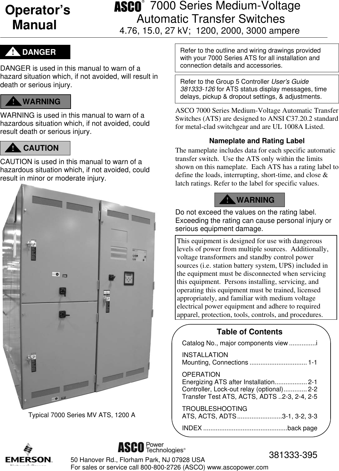
Typical 7000 Series MV ATS, 1200 A
ASCO 7000 Series Medium-Voltage Automatic Transfer
Switches (ATS) are designed to ANSI C37.20.2 standard
for metal-clad switchgear and are UL 1008A Listed.
Nameplate and Rating Label
The nameplate includes data for each specific automatic
transfer switch. Use the ATS only within the limits
shown on this nameplate. Each ATS has a rating label to
define the loads, interrupting, short-time, and close &
latch ratings. Refer to the label for specific values.
Do not exceed the values on the rating label.
Exceeding the rating can cause personal injury or
serious equipment damage.
Refer to the Group 5 Controller User’s Guide
381333-126 for ATS status display messages, time
dela
y
s,
p
icku
p
& dro
p
out settin
g
s, & ad
j
ustments.
Catalog No., major components view ...............i
INSTALLATION
Mounting, Connections ................................ 1-1
OPERATION
Energizing ATS after Installation.................. 2-1
Controller, Lock-out relay (optional).............2-2
Transfer Test ATS, ACTS, ADTS ..2-3, 2-4, 2-5
TROUBLESHOOTING
ATS, ACTS, ADTS.........................3-1, 3-2, 3-3
INDE
X
...............................................back
p
a
g
e
Table of Contents
Refer to the outline and wiring drawings provided
with your 7000 Series ATS for all installation and
connection details and accessories.
DANGER
!
WARNING
!
CAUTION
!
WARNING
!
This equipment is designed for use with dangerous
levels of power from multiple sources. Additionally,
voltage transformers and standby control power
sources (i.e. station battery system, UPS) included in
the equipment must be disconnected when servicing
this equipment. Persons installing, servicing, and
operating this equipment must be trained, licensed
appropriately, and familiar with medium voltage
electrical power equipment and adhere to required
a
pp
arel,
p
rotection, tools, controls, and
p
rocedures.

i Catalog Number 381333-395
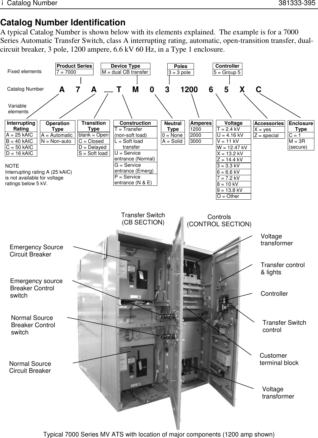
Catalog Number Identification
A typical Catalog Number is shown below with its elements explained. The example is for a 7000
Series Automatic Transfer Switch, class A interrupting rating, automatic, open-transition transfer, dual-
circuit breaker, 3 pole, 1200 ampere, 6.6 kV 60 Hz, in a Type 1 enclosure.
Typical 7000 Series MV ATS with location of major components (1200 amp shown)
A 7 A T M 0 3 1200 6 5 X C
Interrupting
Rating
A = 25 kAIC
B = 40 kAIC
C = 50 kAIC
D = 16 kAIC
Operation
Type
A = Automatic
N = Non-auto
Transition
Type
blank = Open
C = Closed
D = Delayed
S = Soft load
Construction
T = Transfer
(non-soft load)
L = Soft load
transfer
U = Service
entrance (Normal)
G = Service
entrance (Emerg)
P = Service
entrance (N & E)
Fixed elements
Catalo
g
Numbe
r
Variable
elements
Poles
3 = 3 pole Controller
5 = Group 5
Neutral
Type
0 = None
A = Solid
Device Type
M = dual CB transfer
Amperes
1200
2000
3000
Enclosure
Type
C = 1
M = 3R
(secure)
Accessories
X = yes
Z = special
Voltage
T = 2.4 kV
U = 4.16 kV
V = 11 kV
W = 12.47 kV
X = 13.2 kV
Z = 14.4 kV
3 = 3.3 kV
6 = 6.6 kV
7 = 7.2 kV
8 = 10 kV
9 = 13.8 kV
O = Other
Product Series
7 = 7000
NOTE
Interrupting rating A (25 kAIC)
is not available for voltage
ratings below 5 kV.
Controller
Customer
terminal block
Emergency Source
Circuit Breaker
Normal Source
Circuit Breaker
Transfer Switch
(
CB SECTION
)
Controls
(
CONTROL SECTION
)
Transfer control
& lights
Emergency source
Breaker Control
switch
Normal Source
Breaker Control
switch
Transfer Switch
control
Voltage
transformer
Voltage
transformer

381333-395 Installation 1-1
Installation
The ASCO 7000 Series Medium-Voltage Automatic
Transfer Switch (ATS) is factory wired and tested.
Supporting Structure
The supporting foundation for the enclosure must be
level and straight. Refer to the applicable enclosure
outline drawing included with the transfer switch for
all mounting details including door opening space.
Mounting
Refer to the outline and mounting diagram and mount
the automatic transfer switch according to details and
instructions shown on the diagram.
Protect the transfer switch from construction grit and
metal chips to prevent malfunction or shortened life
of the transfer switch.
Testing Power Conductors
Do not connect the power conductors to the transfer
switch until they are tested. Installing power cables in
conduit, cable troughs, and ceiling-suspended hangers
often requires considerable force. The pulling of
cables can damage insulation and stretch or break the
conductor’s strands. For this reason, after the cables
are pulled into position, and before they are connected,
they should be tested to verify that they are not
defective or have been damaged during installation.
Line Connections
Refer to the wiring diagram provided with the transfer
switch. All wiring must be made in accordance with
the National Electrical Code and local codes.
De-energize all conductors, open all circuit
breakers, and rack out all voltage transformers
before making any connections. De-energize any
UPS, station battery system, or any similar
system providing standby control power. Be sure
that the Normal and Emergency line connections
are in proper phase rotation. Place the engine
generator starting control in the OFF position.
Make sure engine generator is not in operation.
Engine-Generator Control
Connections
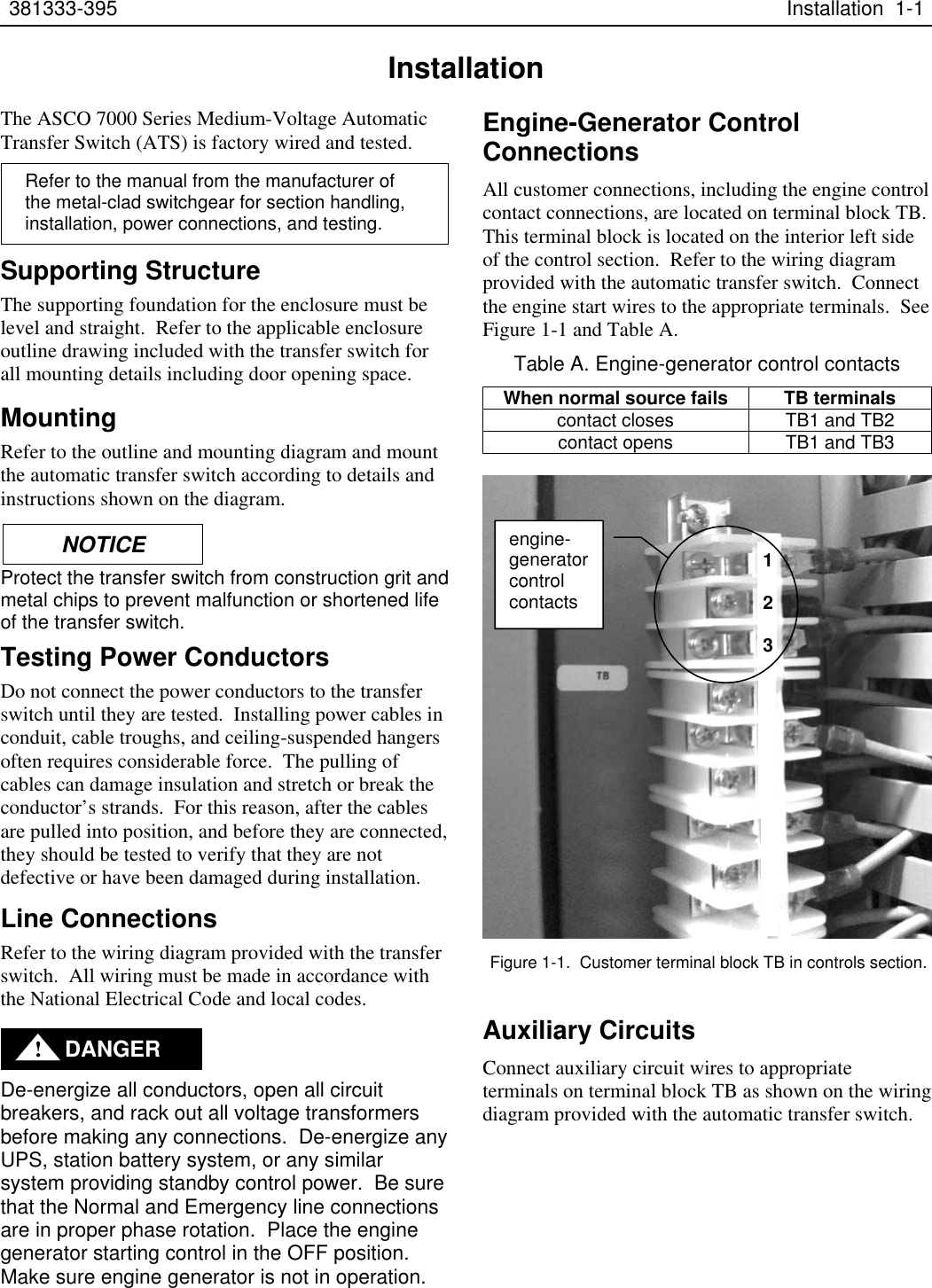
All customer connections, including the engine control
contact connections, are located on terminal block TB.
This terminal block is located on the interior left side
of the control section. Refer to the wiring diagram
provided with the automatic transfer switch. Connect
the engine start wires to the appropriate terminals. See
Figure 1-1 and Table A.
Table A. Engine-generator control contacts
When normal source fails TB terminals
contact closes TB1 and TB2
contact opens TB1 and TB3
Auxiliary Circuits
Connect auxiliary circuit wires to appropriate
terminals on terminal block TB as shown on the wiring
diagram provided with the automatic transfer switch.
Figure 1-1. Customer terminal block TB in controls section.
Refer to the manual from the manufacturer of
the metal-clad switchgear for section handling,
installation, power connections, and testing.
engine-
generator
control
contacts
NOTIC
E
DANGER
!
1
2
3

2-1 Operation 381333-395
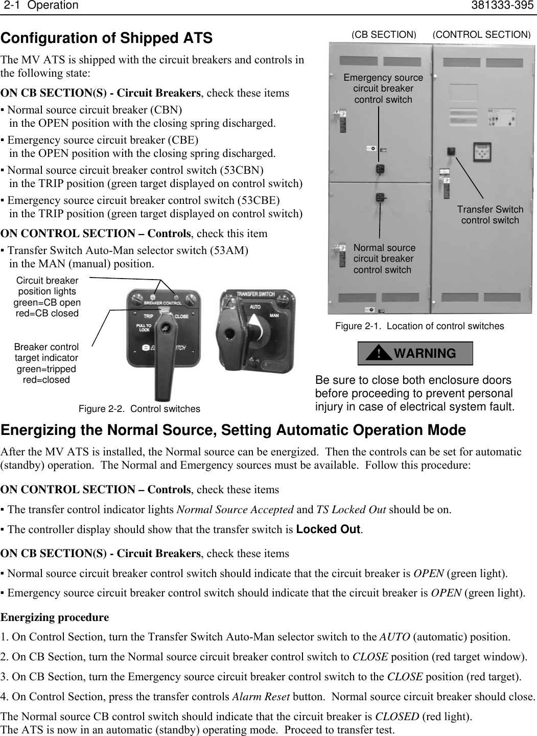
Configuration of Shipped ATS
The MV ATS is shipped with the circuit breakers and controls in
the following state:
ON CB SECTION(S) - Circuit Breakers, check these items
▪ Normal source circuit breaker (CBN)
in the OPEN position with the closing spring discharged.
▪ Emergency source circuit breaker (CBE)
in the OPEN position with the closing spring discharged.
▪ Normal source circuit breaker control switch (53CBN)
in the TRIP position (green target displayed on control switch)
▪ Emergency source circuit breaker control switch (53CBE)
in the TRIP position (green target displayed on control switch)
ON CONTROL SECTION – Controls, check this item
▪ Transfer Switch Auto-Man selector switch (53AM)
in the MAN (manual) position.
Energizing the Normal Source, Setting Automatic Operation Mode
After the MV ATS is installed, the Normal source can be energized. Then the controls can be set for automatic
(standby) operation. The Normal and Emergency sources must be available. Follow this procedure:
ON CONTROL SECTION – Controls, check these items
▪ The transfer control indicator lights Normal Source Accepted and TS Locked Out should be on.
▪ The controller display should show that the transfer switch is Locked Out.
ON CB SECTION(S) - Circuit Breakers, check these items
▪ Normal source circuit breaker control switch should indicate that the circuit breaker is OPEN (green light).
▪ Emergency source circuit breaker control switch should indicate that the circuit breaker is OPEN (green light).
Energizing procedure
1. On Control Section, turn the Transfer Switch Auto-Man selector switch to the AUTO (automatic) position.
2. On CB Section, turn the Normal source circuit breaker control switch to CLOSE position (red target window).
3. On CB Section, turn the Emergency source circuit breaker control switch to the CLOSE position (red target).
4. On Control Section, press the transfer controls Alarm Reset button. Normal source circuit breaker should close.
The Normal source CB control switch should indicate that the circuit breaker is CLOSED (red light).
The ATS is now in an automatic (standby) operating mode. Proceed to transfer test.
Emergency source
circuit breaker
control switch
Normal source
circuit breaker
control switch
Transfer Switch
control switch
Figure 2-1. Location of control switches
Figure 2-2. Control switches
Breaker control
target indicator
green=tripped
red=closed
Circuit breaker
position lights
green=CB open
red=CB closed
WARNING
!
Be sure to close both enclosure doors
before proceeding to prevent personal
injury in case of electrical system fault.
(
CB SECTION
)
(
CONTROL SECTION
)

381333-395 Operation 2-2
Controller Settings for MV ATSs
The Group 5 Controller is factory set for medium-
voltage operation. These are the special settings:
Controller Voltage Jumper Blocks
The control voltage is typically stepped down to 120V,
so the eight jumper blocks are factory arranged
horizontally for 120 V input.
Controller Menu Settings
ATS Information Rating is 1200, 2000, or 3000 A
The ATS information rating setting is 1200A, 2000A,
or 3000A.
ATS Information is Circuit Breaker Non Bypass
The ATS information type setting is BRKR NBPS.
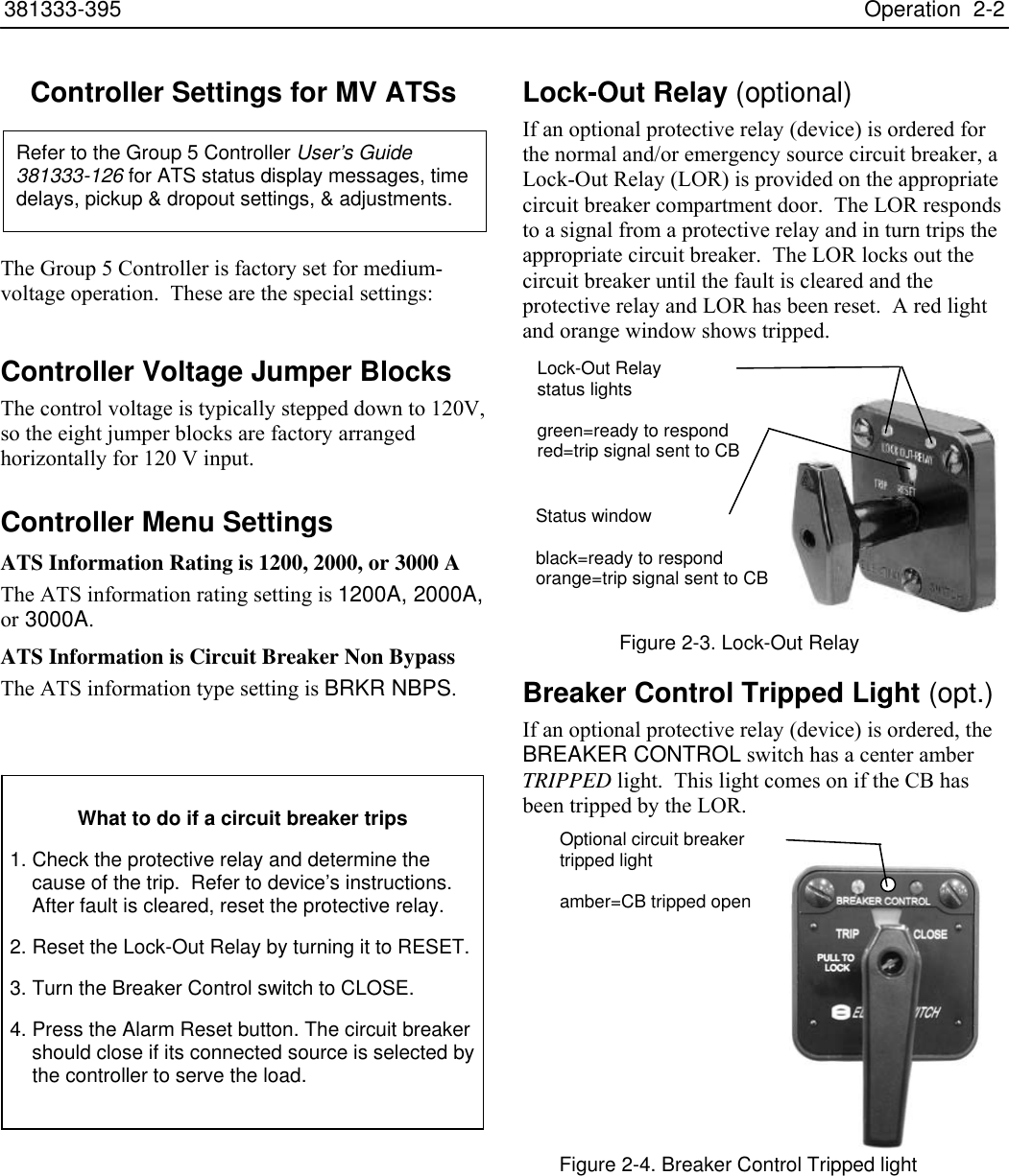
Lock-Out Relay (optional)
If an optional protective relay (device) is ordered for
the normal and/or emergency source circuit breaker, a
Lock-Out Relay (LOR) is provided on the appropriate
circuit breaker compartment door. The LOR responds
to a signal from a protective relay and in turn trips the
appropriate circuit breaker. The LOR locks out the
circuit breaker until the fault is cleared and the
protective relay and LOR has been reset. A red light
and orange window shows tripped.
Breaker Control Tripped Light (opt.)
If an optional protective relay (device) is ordered, the
BREAKER CONTROL switch has a center amber
TRIPPED light. This light comes on if the CB has
been tripped by the LOR.
Refer to the Group 5 Controller User’s Guide
381333-126 for ATS status display messages, time
delays, pickup & dropout settings, & adjustments.
Optional circuit breaker
tripped light
amber=CB tripped open
Lock-Out Relay
status lights
green=ready to respond
red=trip signal sent to CB
Status window
black=ready to respond
orange=trip signal sent to CB
Fi
g
ure 2-3. Lock-Out Rela
y
Figure 2-4. Breaker Control Tripped light
What to do if a circuit breaker trips
1. Check the protective relay and determine the
cause of the trip. Refer to device’s instructions.
After fault is cleared, reset the protective relay.
2. Reset the Lock-Out Relay by turning it to RESET.
3. Turn the Breaker Control switch to CLOSE.
4. Press the Alarm Reset button. The circuit breaker
should close if its connected source is selected by
the controller to serve the load.

2-3 Operation 381333-395
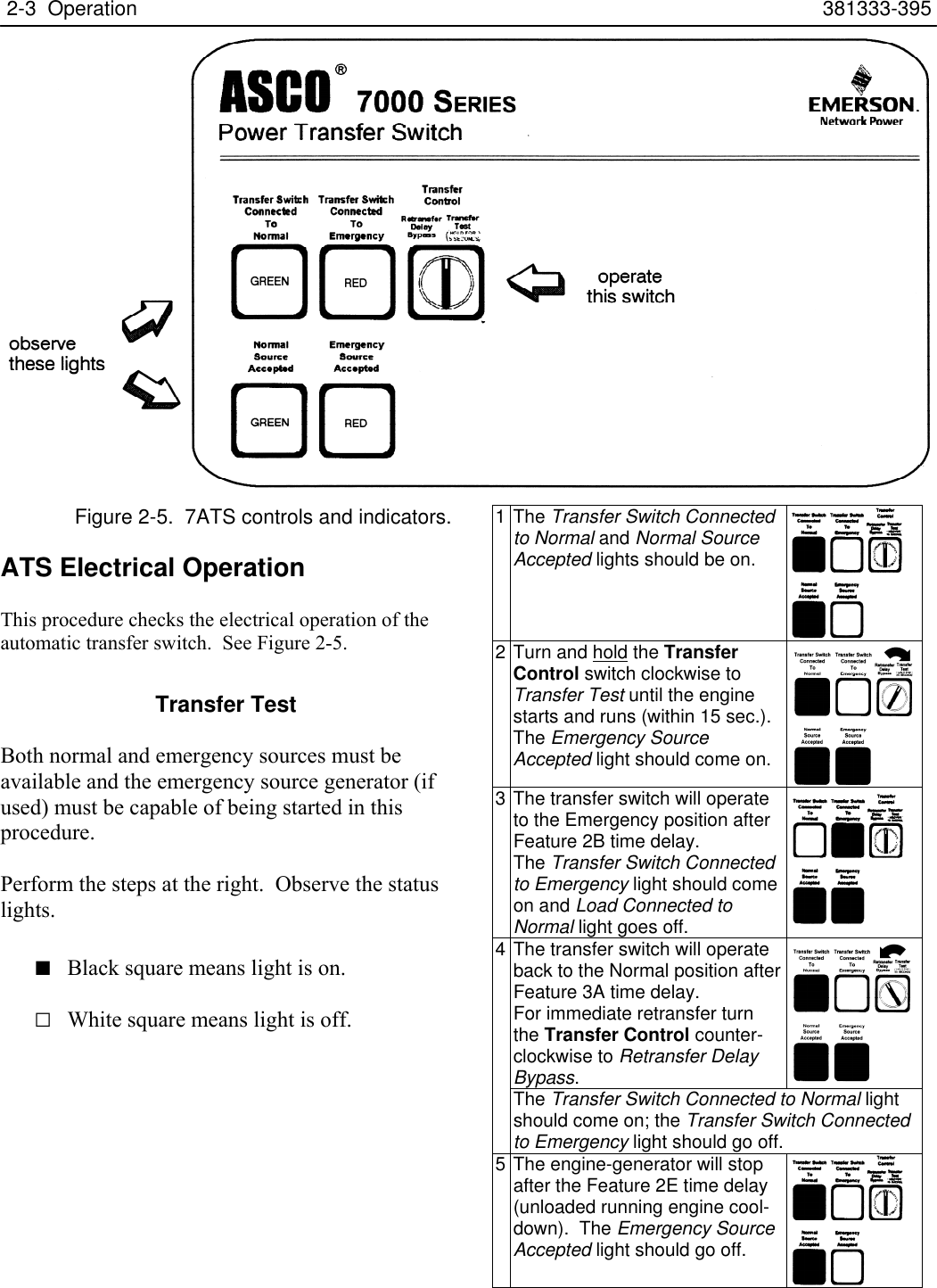
Figure 2-5. 7ATS controls and indicators.
ATS Electrical Operation
This procedure checks the electrical operation of the
automatic transfer switch. See Figure 2-5.
Transfer Test
Both normal and emergency sources must be
available and the emergency source generator (if
used) must be capable of being started in this
procedure.
Perform the steps at the right. Observe the status
lights.
■ Black square means light is on.
□ White square means light is off.
1 The Transfer Switch Connected
to Normal and Normal Source
Accepted lights should be on.
2 Turn and hold the Transfer
Control switch clockwise to
Transfer Test until the engine
starts and runs (within 15 sec.).
The Emergency Source
Accepted light should come on.
3 The transfer switch will operate
to the Emergency position after
Feature 2B time delay.
The Transfer Switch Connected
to Emergency light should come
on and Load Connected to
Normal light goes off.
The transfer switch will operate
back to the Normal position after
Feature 3A time delay.
For immediate retransfer turn
the Transfer Control counter-
clockwise to Retransfer Delay
Bypass.
4
The Transfer Switch Connected to Normal light
should come on; the Transfer Switch Connected
to Emergency light should go off.
5 The engine-generator will stop
after the Feature 2E time delay
(unloaded running engine cool-
down). The Emergency Source
Accepted light should go off.

381333-395 Operation 2-4
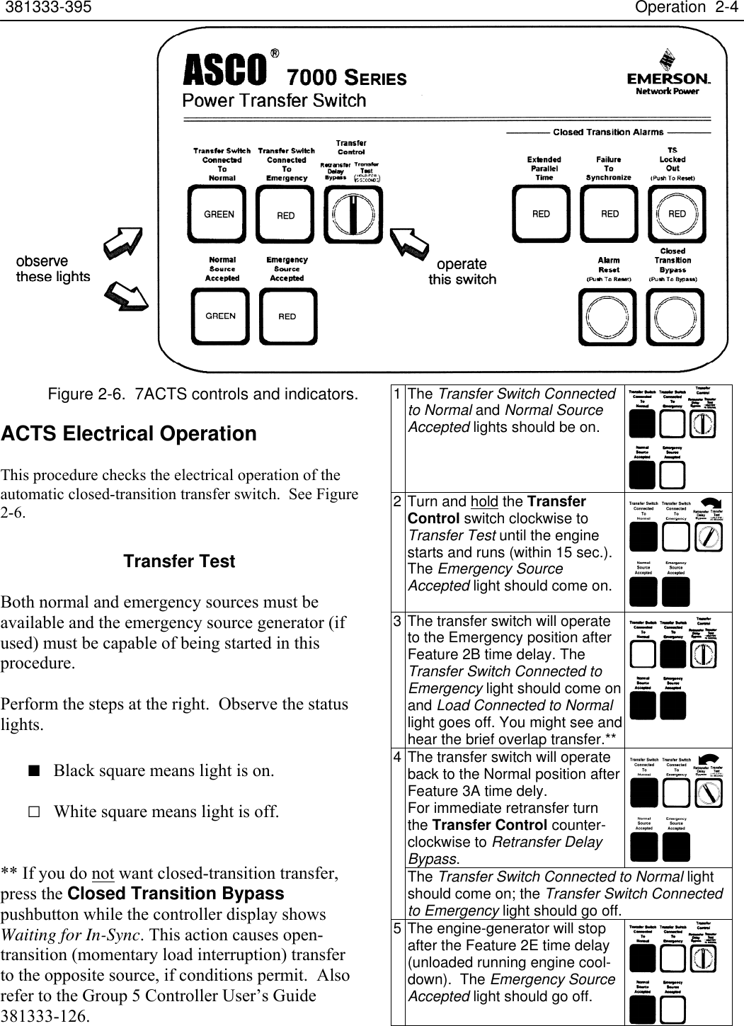
Figure 2-6. 7ACTS controls and indicators.
ACTS Electrical Operation
This procedure checks the electrical operation of the
automatic closed-transition transfer switch. See Figure
2-6.
Transfer Test
Both normal and emergency sources must be
available and the emergency source generator (if
used) must be capable of being started in this
procedure.
Perform the steps at the right. Observe the status
lights.
■ Black square means light is on.
□ White square means light is off.
** If you do not want closed-transition transfer,
press the Closed Transition Bypass
pushbutton while the controller display shows
Waiting for In-Sync. This action causes open-
transition (momentary load interruption) transfer
to the opposite source, if conditions permit. Also
refer to the Group 5 Controller User’s Guide
381333-126.
1 The Transfer Switch Connected
to Normal and Normal Source
Accepted lights should be on.
2 Turn and hold the Transfer
Control switch clockwise to
Transfer Test until the engine
starts and runs (within 15 sec.).
The Emergency Source
Accepted light should come on.
3 The transfer switch will operate
to the Emergency position after
Feature 2B time delay. The
Transfer Switch Connected to
Emergency light should come on
and Load Connected to Normal
light goes off. You might see and
hear the brief overlap transfer.**
The transfer switch will operate
back to the Normal position after
Feature 3A time dely.
For immediate retransfer turn
the Transfer Control counter-
clockwise to Retransfer Delay
Bypass.
4
The Transfer Switch Connected to Normal light
should come on; the Transfer Switch Connected
to Emergency light should go off.
5 The engine-generator will stop
after the Feature 2E time delay
(unloaded running engine cool-
down). The Emergency Source
Accepted light should go off.

2-5 Operation 381333-395
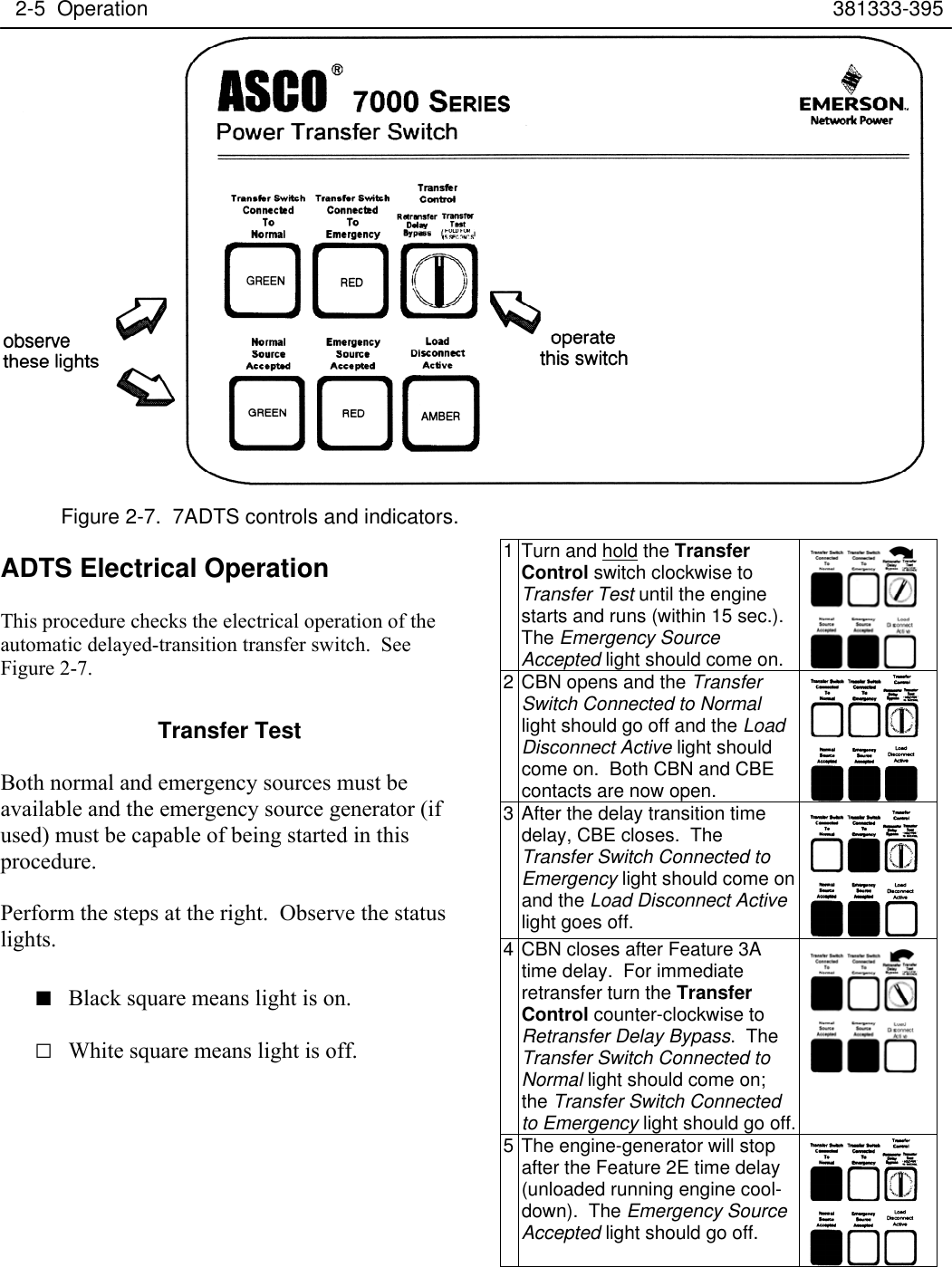
Figure 2-7. 7ADTS controls and indicators.
ADTS Electrical Operation
This procedure checks the electrical operation of the
automatic delayed-transition transfer switch. See
Figure 2-7.
Transfer Test
Both normal and emergency sources must be
available and the emergency source generator (if
used) must be capable of being started in this
procedure.
Perform the steps at the right. Observe the status
lights.
■ Black square means light is on.
□ White square means light is off.
1 Turn and hold the Transfer
Control switch clockwise to
Transfer Test until the engine
starts and runs (within 15 sec.).
The Emergency Source
Accepted light should come on.
2 CBN opens and the Transfer
Switch Connected to Normal
light should go off and the Load
Disconnect Active light should
come on. Both CBN and CBE
contacts are now open.
3 After the delay transition time
delay, CBE closes. The
Transfer Switch Connected to
Emergency light should come on
and the Load Disconnect Active
light goes off.
4 CBN closes after Feature 3A
time delay. For immediate
retransfer turn the Transfer
Control counter-clockwise to
Retransfer Delay Bypass. The
Transfer Switch Connected to
Normal light should come on;
the Transfer Switch Connected
to Emergency light should go off.
5 The engine-generator will stop
after the Feature 2E time delay
(unloaded running engine cool-
down). The Emergency Source
Accepted light should go off.

381333-395 Troubleshooting 3-1
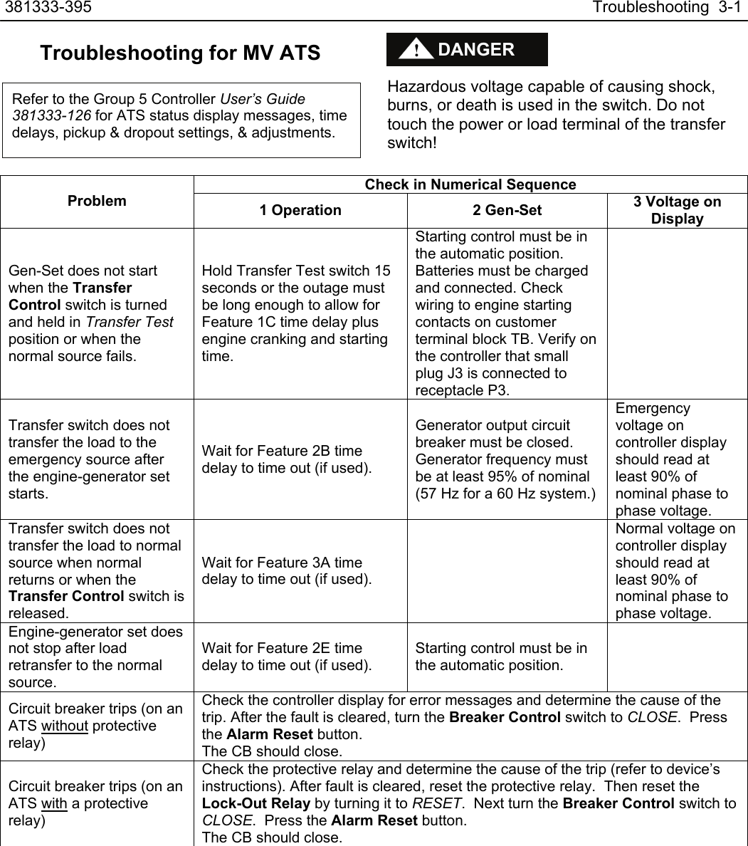
Troubleshooting for MV ATS
Hazardous voltage capable of causing shock,
burns, or death is used in the switch. Do not
touch the power or load terminal of the transfer
switch!
Check in Numerical Sequence
Problem 1 Operation 2 Gen-Set 3 Voltage on
Display
Gen-Set does not start
when the Transfer
Control switch is turned
and held in Transfer Test
position or when the
normal source fails.
Hold Transfer Test switch 15
seconds or the outage must
be long enough to allow for
Feature 1C time delay plus
engine cranking and starting
time.
Starting control must be in
the automatic position.
Batteries must be charged
and connected. Check
wiring to engine starting
contacts on customer
terminal block TB. Verify on
the controller that small
plug J3 is connected to
receptacle P3.
Transfer switch does not
transfer the load to the
emergency source after
the engine-generator set
starts.
Wait for Feature 2B time
delay to time out (if used).
Generator output circuit
breaker must be closed.
Generator frequency must
be at least 95% of nominal
(57 Hz for a 60 Hz system.)
Emergency
voltage on
controller display
should read at
least 90% of
nominal phase to
phase voltage.
Transfer switch does not
transfer the load to normal
source when normal
returns or when the
Transfer Control switch is
released.
Wait for Feature 3A time
delay to time out (if used).
Normal voltage on
controller display
should read at
least 90% of
nominal phase to
phase voltage.
Engine-generator set does
not stop after load
retransfer to the normal
source.
Wait for Feature 2E time
delay to time out (if used).
Starting control must be in
the automatic position.
Circuit breaker trips (on an
ATS without protective
relay)
Check the controller display for error messages and determine the cause of the
trip. After the fault is cleared, turn the Breaker Control switch to CLOSE. Press
the Alarm Reset button.
The CB should close.
Circuit breaker trips (on an
ATS with a protective
relay)
Check the protective relay and determine the cause of the trip (refer to device’s
instructions). After fault is cleared, reset the protective relay. Then reset the
Lock-Out Relay by turning it to RESET. Next turn the Breaker Control switch to
CLOSE. Press the Alarm Reset button.
The CB should close.
Refer to the Group 5 Controller User’s Guide
381333-126 for ATS status display messages, time
delays, pickup & dropout settings, & adjustments.
DANGER
!

3-2 Troubleshooting 381333-395
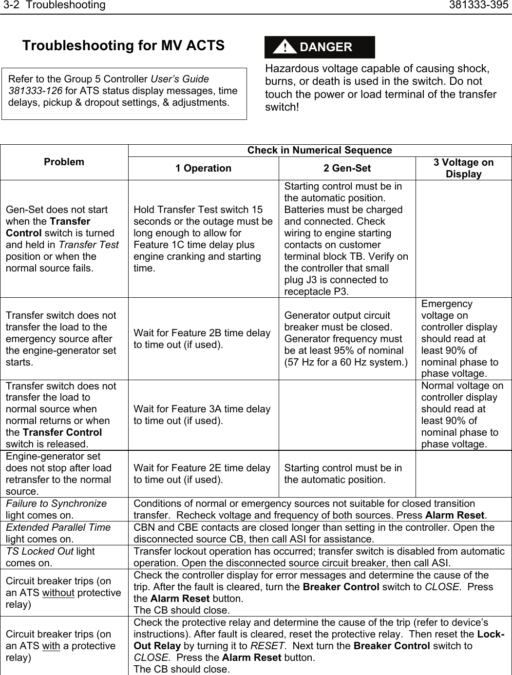
Troubleshooting for MV ACTS
Hazardous voltage capable of causing shock,
burns, or death is used in the switch. Do not
touch the power or load terminal of the transfer
switch!
Check in Numerical Sequence
Problem 1 Operation 2 Gen-Set 3 Voltage on
Display
Gen-Set does not start
when the Transfer
Control switch is turned
and held in Transfer Test
position or when the
normal source fails.
Hold Transfer Test switch 15
seconds or the outage must be
long enough to allow for
Feature 1C time delay plus
engine cranking and starting
time.
Starting control must be in
the automatic position.
Batteries must be charged
and connected. Check
wiring to engine starting
contacts on customer
terminal block TB. Verify on
the controller that small
plug J3 is connected to
receptacle P3.
Transfer switch does not
transfer the load to the
emergency source after
the engine-generator set
starts.
Wait for Feature 2B time delay
to time out (if used).
Generator output circuit
breaker must be closed.
Generator frequency must
be at least 95% of nominal
(57 Hz for a 60 Hz system.)
Emergency
voltage on
controller display
should read at
least 90% of
nominal phase to
phase voltage.
Transfer switch does not
transfer the load to
normal source when
normal returns or when
the Transfer Control
switch is released.
Wait for Feature 3A time delay
to time out (if used).
Normal voltage on
controller display
should read at
least 90% of
nominal phase to
phase voltage.
Engine-generator set
does not stop after load
retransfer to the normal
source.
Wait for Feature 2E time delay
to time out (if used).
Starting control must be in
the automatic position.
Failure to Synchronize
light comes on.
Conditions of normal or emergency sources not suitable for closed transition
transfer. Recheck voltage and frequency of both sources. Press Alarm Reset.
Extended Parallel Time
light comes on.
CBN and CBE contacts are closed longer than setting in the controller. Open the
disconnected source CB, then call ASI for assistance.
TS Locked Out light
comes on.
Transfer lockout operation has occurred; transfer switch is disabled from automatic
operation. Open the disconnected source circuit breaker, then call ASI.
Circuit breaker trips (on
an ATS without protective
relay)
Check the controller display for error messages and determine the cause of the
trip. After the fault is cleared, turn the Breaker Control switch to CLOSE. Press
the Alarm Reset button.
The CB should close.
Circuit breaker trips (on
an ATS with a protective
relay)
Check the protective relay and determine the cause of the trip (refer to device’s
instructions). After fault is cleared, reset the protective relay. Then reset the Lock-
Out Relay by turning it to RESET. Next turn the Breaker Control switch to
CLOSE. Press the Alarm Reset button.
The CB should close.
Refer to the Group 5 Controller User’s Guide
381333-126 for ATS status display messages, time
delays, pickup & dropout settings, & adjustments.
DANGER
!

381333-395 Troubleshooting 3-3
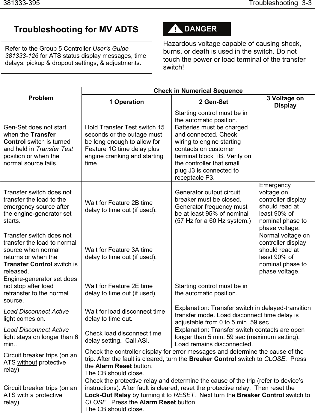
Troubleshooting for MV ADTS
Hazardous voltage capable of causing shock,
burns, or death is used in the switch. Do not
touch the power or load terminal of the transfer
switch!
Check in Numerical Sequence
Problem 1 Operation 2 Gen-Set 3 Voltage on
Display
Gen-Set does not start
when the Transfer
Control switch is turned
and held in Transfer Test
position or when the
normal source fails.
Hold Transfer Test switch 15
seconds or the outage must
be long enough to allow for
Feature 1C time delay plus
engine cranking and starting
time.
Starting control must be in
the automatic position.
Batteries must be charged
and connected. Check
wiring to engine starting
contacts on customer
terminal block TB. Verify on
the controller that small
plug J3 is connected to
receptacle P3.
Transfer switch does not
transfer the load to the
emergency source after
the engine-generator set
starts.
Wait for Feature 2B time
delay to time out (if used).
Generator output circuit
breaker must be closed.
Generator frequency must
be at least 95% of nominal
(57 Hz for a 60 Hz system.)
Emergency
voltage on
controller display
should read at
least 90% of
nominal phase to
phase voltage.
Transfer switch does not
transfer the load to normal
source when normal
returns or when the
Transfer Control switch is
released.
Wait for Feature 3A time
delay to time out (if used).
Normal voltage on
controller display
should read at
least 90% of
nominal phase to
phase voltage.
Engine-generator set does
not stop after load
retransfer to the normal
source.
Wait for Feature 2E time
delay to time out (if used).
Starting control must be in
the automatic position.
Load Disconnect Active
light comes on.
Wait for load disconnect time
delay to time out.
Explanation: Transfer switch in delayed-transition
transfer mode. Load disconnect time delay is
adjustable from 0 to 5 min. 59 sec.
Load Disconnect Active
light stays on longer than 6
min..
Check load disconnect time
delay setting. Call ASI.
Explanation: Transfer switch contacts are open
longer than 5 min. 59 sec (maximum setting).
Load remains disconnected.
Circuit breaker trips (on an
ATS without protective
relay)
Check the controller display for error messages and determine the cause of the
trip. After the fault is cleared, turn the Breaker Control switch to CLOSE. Press
the Alarm Reset button.
The CB should close.
Circuit breaker trips (on an
ATS with a protective
relay)
Check the protective relay and determine the cause of the trip (refer to device’s
instructions). After fault is cleared, reset the protective relay. Then reset the
Lock-Out Relay by turning it to RESET. Next turn the Breaker Control switch to
CLOSE. Press the Alarm Reset button.
The CB should close.
Refer to the Group 5 Controller User’s Guide
381333-126 for ATS status display messages, time
delays, pickup & dropout settings, & adjustments.
DANGER
!
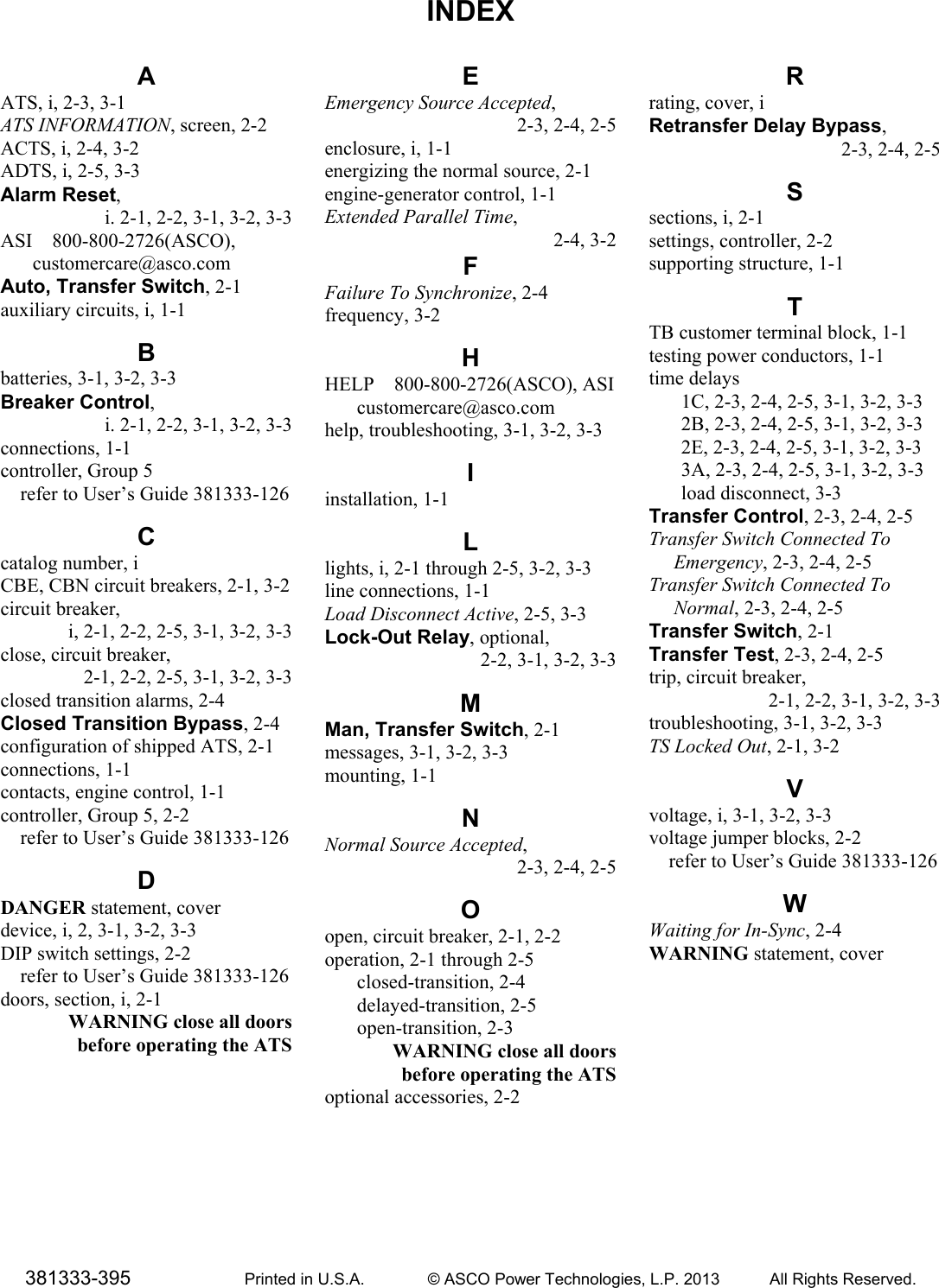
INDEX
381333-395 Printed in U.S.A. © ASCO Power Technologies, L.P. 2013 All Rights Reserved.
A
ATS, i, 2-3, 3-1
ATS INFORMATION, screen, 2-2
ACTS, i, 2-4, 3-2
ADTS, i, 2-5, 3-3
Alarm Reset,
i. 2-1, 2-2, 3-1, 3-2, 3-3
ASI 800-800-2726(ASCO),
customercare@asco.com
Auto, Transfer Switch, 2-1
auxiliary circuits, i, 1-1
B
batteries, 3-1, 3-2, 3-3
Breaker Control,
i. 2-1, 2-2, 3-1, 3-2, 3-3
connections, 1-1
controller, Group 5
refer to User’s Guide 381333-126
C
catalog number, i
CBE, CBN circuit breakers, 2-1, 3-2
circuit breaker,
i, 2-1, 2-2, 2-5, 3-1, 3-2, 3-3
close, circuit breaker,
2-1, 2-2, 2-5, 3-1, 3-2, 3-3
closed transition alarms, 2-4
Closed Transition Bypass, 2-4
configuration of shipped ATS, 2-1
connections, 1-1
contacts, engine control, 1-1
controller, Group 5, 2-2
refer to User’s Guide 381333-126
D
DANGER statement, cover
device, i, 2, 3-1, 3-2, 3-3
DIP switch settings, 2-2
refer to User’s Guide 381333-126
doors, section, i, 2-1
WARNING close all doors
before operating the ATS
E
Emergency Source Accepted,
2-3, 2-4, 2-5
enclosure, i, 1-1
energizing the normal source, 2-1
engine-generator control, 1-1
Extended Parallel Time,
2-4, 3-2
F
Failure To Synchronize, 2-4
frequency, 3-2
H
HELP 800-800-2726(ASCO), ASI
customercare@asco.com
help, troubleshooting, 3-1, 3-2, 3-3
I
installation, 1-1
L
lights, i, 2-1 through 2-5, 3-2, 3-3
line connections, 1-1
Load Disconnect Active, 2-5, 3-3
Lock-Out Relay, optional,
2-2, 3-1, 3-2, 3-3
M
Man, Transfer Switch, 2-1
messages, 3-1, 3-2, 3-3
mounting, 1-1
N
Normal Source Accepted,
2-3, 2-4, 2-5
O
open, circuit breaker, 2-1, 2-2
operation, 2-1 through 2-5
closed-transition, 2-4
delayed-transition, 2-5
open-transition, 2-3
WARNING close all doors
before operating the ATS
optional accessories, 2-2
R
rating, cover, i
Retransfer Delay Bypass,
2-3, 2-4, 2-5
S
sections, i, 2-1
settings, controller, 2-2
supporting structure, 1-1
T
TB customer terminal block, 1-1
testing power conductors, 1-1
time delays
1C, 2-3, 2-4, 2-5, 3-1, 3-2, 3-3
2B, 2-3, 2-4, 2-5, 3-1, 3-2, 3-3
2E, 2-3, 2-4, 2-5, 3-1, 3-2, 3-3
3A, 2-3, 2-4, 2-5, 3-1, 3-2, 3-3
load disconnect, 3-3
Transfer Control, 2-3, 2-4, 2-5
Transfer Switch Connected To
Emergency, 2-3, 2-4, 2-5
Transfer Switch Connected To
Normal, 2-3, 2-4, 2-5
Transfer Switch, 2-1
Transfer Test, 2-3, 2-4, 2-5
trip, circuit breaker,
2-1, 2-2, 3-1, 3-2, 3-3
troubleshooting, 3-1, 3-2, 3-3
TS Locked Out, 2-1, 3-2
V
voltage, i, 3-1, 3-2, 3-3
voltage jumper blocks, 2-2
refer to User’s Guide 381333-126
W
Waiting for In-Sync, 2-4
WARNING statement, cover