Emerson Asco 7000 Series Power Transfer Switch Brochures And Data Sheets
2015-03-30
: Emerson Emerson-Asco-7000-Series-Power-Transfer-Switch-Brochures-And-Data-Sheets-680096 emerson-asco-7000-series-power-transfer-switch-brochures-and-data-sheets-680096 emerson pdf
Open the PDF directly: View PDF ![]() .
.
Page Count: 28


2
Healthcare Facilities
Web Hosting, Internet Data Centers
Commercial Buildings / Industrial Buildings
Telecom Central Offices
Process Manufacturing
Distributed Power / Load Management
As we become more depen-
dent on the quality and
reliability of electrical power,
interruption or complete loss
of power can create serious
and even crippling financial
losses, or impose dangers to
life and safety.
ASCO Power Technologies
(ASCO) provides the solu-
tions to handle the transfer
of critical loads to emer-
gency sources reliably and
with state of the art prod-
ucts. Using ASCO products
can mean the difference
between a minor inconve-
nience and a major catastro-
phe. You’ll find ASCO Power
Transfer Switches wherever
there is a critical load to be
protected.
When flexibility in power
switching is a must, ASCO
offers a variety of product
solutions to meet virtually
every application require-
ment, including distributed
generation applications.
That’s why the 7000 SerieS
is available in open, delayed,
closed and closed soft load
configurations. Additionally,
switched or overlapping
neutral options provide for
reliable operation of ground
fault protection systems and
reduction of voltage tran-
sients from unbalanced load
switching.
ASCO Power Transfer
Switches are the first CE
Marked, IEC 60947-6-1
compliant Transfer Switches
in the world.
ASCO 7000 Series
Power Transfer Switches
Critical Loads Demand ASCO
Protecting:
The Recognized Leader in Power Transfer
Switch Technology Offers the Most
Advanced Transfer Switches in the World.
• Conventional two-position transfer configuration,
plus closed and delayed transition modes of operation.
All configurations available with either automatic or
non-automatic control.
• UL listed to 1008 Transfer Switch Equipment &
CSA certified to CSA 22.2 No.178-1978 Automatic
Transfer Switches.
• Qualified and certified to IEC 60947-6-1, CE marked
(optional). (Limited to certain accessories.)
• Rated up to 600 VAC, 30 through 4000 Amperes.
• Reliable and field proven solenoid operating mechanism.
• High withstand and close-on ratings including short time
withstand current rating for optimum flexibility in circuit
breaker coordination (600-4000 Amperes).
• Solid, switched, or overlapping neutral conductor options.
ASCO Power Transfer Switches are the standard of the
industry. High speed transfer of loads between alter-
nate sources of power, regardless of ampacity size, is
achieved by a reliable, field proven solenoid operating
mechanism. When combined with a programmable
microprocessor controller with keypad and LCD display,
they offer the most advanced method of transferring
all types of loads, such as motors, electronic drives,
UPS’s and microprocessor based systems. 7000 SerieS
Power Transfer Switches are available open or enclosed,
in ampacity sizes from 30 through 4000 Amperes with
the largest selection of optional accessories offered any-
where. All switching configurations are available with an
integrally mounted bypass-isolation switch and/or rated
for use in service entrance applications.
• Front replaceable main and arcing contacts (800-4000 Amperes).
• Programmable microprocessor controller with keypad and
LCD display.
• Centrally located terminal block for customer control
connections (260-4000 Amperes).
• 16mm, industrial grade control switches and indicating lights.
• Switch position LED indicators and source acceptability lights.
• Standard ground conductor connections.
• Four auxiliary contacts, two contacts closed when switch
is in normal position and two contacts closed when switch
is in emergency position.
• Local/remote communications capability for interfacing
with ASCO POWERQUEST® communication products.
3
7000 series
7000 series Power Transfer Switches Product Features
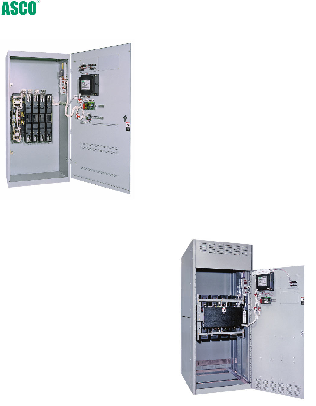
Fig. 1: Three Pole 7000 SerieS Automatic Transfer Switch
rated 1600 Amperes (shown with optional front
connected terminals and Power Manager).
Delayed Transition Transfer Switching
Fig. 3: Four pole, Delayed Transition
Transfer Switch rated 2000 Amperes.
ASCO Delayed Transition Transfer Switches are designed
to provide transfer of loads between power sources with a
timed load disconnect position for an adjustable period of
time. Applications include older style variable frequency
drives, rectifier banks, and load management applications.
• Available in 150 through 4000 Amperes.
• Utilizes reliable, field proven solenoid operating
mechanisms.
• Mechanical interlocks to prevent direct connection
of both sources.
• Indicator light (16mm, industrial grade
type LED) for load disconnect position.
• Adjustable time delay for load disconnect position.
Closed Transition Transfer Switching
ASCO Automatic Closed Transition Transfer Switches feature
main contacts that overlap, permitting the transfer of electrical
loads without power interruption. The switch transfers in a
make-before-break mode if both sources are within acceptable
parameters. Control logic continuously monitors source
conditions and automatically determines whether the load
transfer should be open (conventional non-overlap mode) or
closed transition. Available 150 through 4000 Amperes.
Closed Transition Transfer within 5 electrical degrees is achieved
passively, without control of engine generator set. Therefore,
no additional control wire runs are required between the ATS and
engine generator set governor. Plus, protective relaying may
not be required under normal operation since the contact over-
lap time is less than 100 milliseconds (consult your local utility
on protective relay requirements).
Failure to synchronize indication and extended parallel time
protection is built-in to all 7000 SerieS closed transition
controls to prevent abnormal operation.
Fig. 2: Four pole, Closed Transition Transfer Switch
rated 1000 Amperes in Type 1 enclosure.
4
7000 series Power Switching Solutions
Non-Automatic Transfer Switching
ASCO Non-Automatic Transfer Switches are electrically operated
units which are operated with manual control switches mounted
locally or at remote locations.
• Sizes from 30 through 4000 Amperes.
• Microprocessor based controller provides for addition of
optional accessories.
• Controller prevents inadvertent operation under low
voltage conditions.
• Low control circuit operating currents allow for long line runs
between remotely mounted manual control switches and the
transfer switch.
• Source acceptability lights inform operator if sources
are available to accept load.
• Standard inphase monitor can be activated for
transferring motor loads.
Fig. 4: Three pole Non-Automatic,
electrically operated 400 ampere switch
shown in Type 1 enclosure.
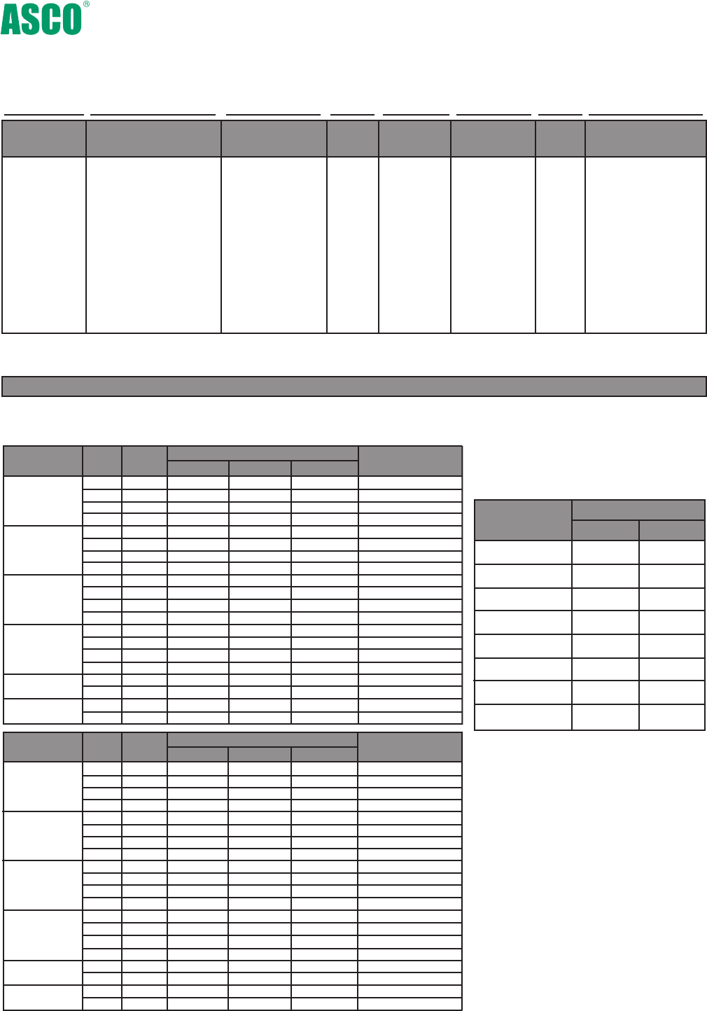
5
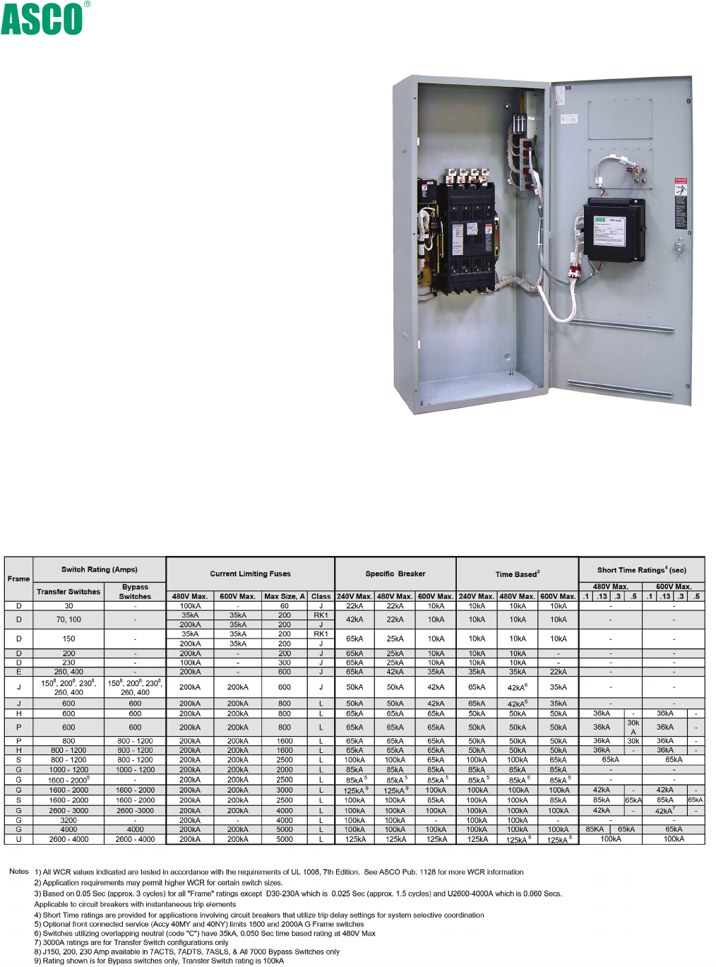
7000 series Power Switching Solutions
Withstand and Close-On Ratings for all 7000 series Products1,2
(RMS Symmetrical Amps)
Automatic Transfer Bypass-Isolation Switches
ASCO Automatic Transfer & Bypass-Isolation Switches are
available in open transition, closed transition and delayed
transition designs. The bypass and isolation features allow
the primary automatic transfer switch to be inspected, tested,
and maintained without any interruption of power to the load.
They also provide redundant power transfer in the event the
ATS is disabled or removed from service.
• Available 150 to 4000 Amperes.
• Allows bypass-isolation without load interruption.
• Bypass switch and transfer switch have identical electrical
ratings.
• Heavy duty mechanical interlocks prevent undesirable
operation.
• Bypass contacts carry current only during bypass mode.
• Transfer switch is drawout design for ease of maintenance.
• Bypass and isolation handles are permanently mounted.
The bypass switch has dead front quick-make, quick-break
operation for transferring of loads between live sources.
• Bypass switch is fully rated for use as a manual 3-position
transfer switch.
• Bypass and isolation functions are simple, requiring a total
of two operating handles.
• No toggle switches, push buttons, selector switches or
levers are required for bypass-isolation operation.
• Mechanical indicators show bypass and transfer switch
positions.
• 800 -1200 ampere available in shallow depth, front
connected or rear connected designs.
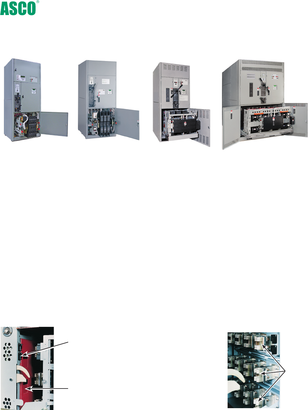
Fig. 6: Rated
600- 1200 Amps
Transfer Switch Drawout Features (150-4000 Amperes)
• Automatic secondary disconnects
remove all control power as switch is
withdrawn.
• Drawout carriage provides for easy
transfer switch maintenance and/or
removal via commercially available
breaker hoists.
• Optional transfer switch lifting yoke
kit available
• Optional automatic shutters which
close when the transfer switch is
withdrawn to provide bus isolation,
specify accessory 82C.(1600-4000A
only)
Automatic
Secondary
Disconnects
Automatic
Shutters
(optional on
1600-4000amps)
Fig. 9: Bypass-Isolation Transfer
Switch secondary disconnects and
optional automatic shutters.
6
Self
Aligning
Jaws
Fig. 10: Bypass-Isolation
Transfer Switch self
aligning power jaws.
7000 series Power Switching Solutions
Fig. 5: Rated
150-600 Amps
Fig. 7: Rated
800-3000 Amps
Fig. 8: Rated
4000 Amps
Push in bypass
handle and turn
it counter
clockwise
7
7000 series Power Switching Solutions
Bypass Switch E
L
N
Automatic Transfer Switch
Bypass Switch E
L
N
Automatic Transfer Switch
Bypass Switch E
L
N
Automatic Transfer Switch
Turn isolation
handle counter
clockwise until
window shows
“Test”
Mechanical isolation handle position
window (connected/test/isolate)
Padlocking
provisions
Mechanical
bypass
switch position
flags
Turn isolation
handle counter
clockwise
until window
shows “Isolate”
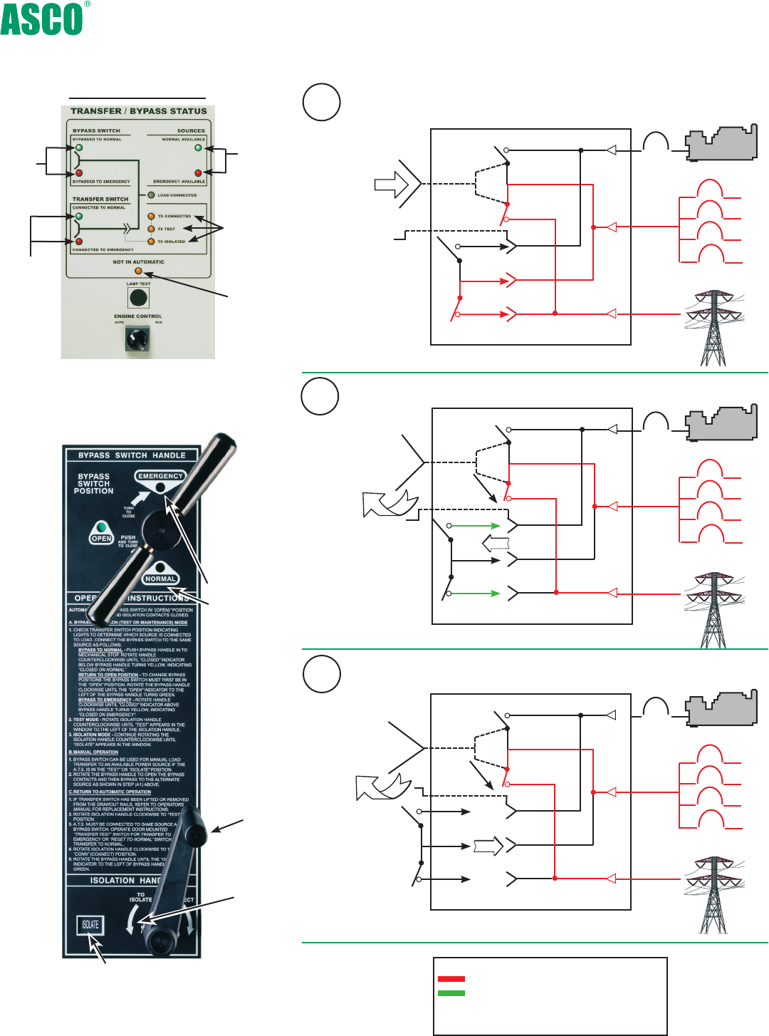
Bypass to Normal
Test Position
Isolation Position
Isolation Handle
Bypass Handle
Isolation Handle
Isolation Handle
Isolation
handle
Bypass and Isolation Handles - Simple as 1, 2, 3
1
2
3
Key:
Represents Current Flow
In test position control panel remains
energized to allow for electrical
operation of a transfer switch.
Fig. 12: Bypass-Isolation
Switch user interface
Source
availability
Bypass
switch
position
Transfer
switch
position
Isolation
handle
position
Not in
“auto”
flashing
LED
Fig. 11: Transfer Bypass
Status Panel*
*Standard on switches up through H 1200A.
Specify ACC 82E for G frame 1600-4000A
LED Indicators
Optional Features
• Enclosures - Secure Double Door
-
UL Type 3R w/strip heater & thermostat
-
UL Type 4 or 4X
-
UL Type 12
• Connections
-
Crimp lugs
-
Bus Riser on Normal, Emergency or Load
• Protective Relays/Metering
-
Accessory
85L , see page 15
• Surge Suppression
- Accessory 73, Surge protector (see pg. 14)
• ASCO POWERQUEST® products (see pages 16-21)
- ASCO 72E Ethernet Connectivity module, page 17
- ASCO 5310/5350 Remote annunciators, page 17
- ASCO 5400 Power Quality Meters, page 17
• Additional Breaker(s)
- Circuit Breaker on Emergency
- Load Distribution Panel
• Optional high AIC ratings on breakers
Consult ASCO for additional features
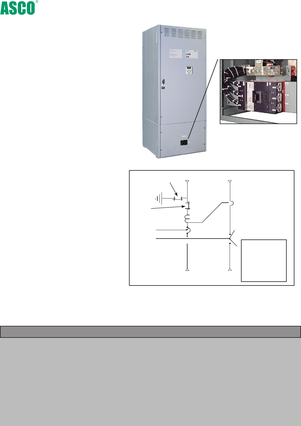
7000 series Service Entrance Power Transfer Switches
The ASCO Service Entrance Power Transfer Switch
combines automatic power switching with a discon-
nect and overcurrent protective device on the utility
source. The power transfer switch meets all National
Electric Code requirements for installation at a facil-
ity’s main utility service entrance. Service entrance
rated transfer switches generally are installed at
facilities that have a single utility feed and a single
emergency power source. A circuit breaker serves
as the utility disconnect and links are provided to
dis-connect both neutral and ground connections.
This product is either UL 1008 or UL 891 listed and is
available up to 600V and 4000A in Standard, Delayed,
Closed Transition, Soft Load, and Bypass Isolation
Configurations.
8
Standard Features
• Available from 150 to 4000 Amperes
• ASCO 7000 SerieS Power Transfer Switch is
UL 1008 Listed
• Standard UL Type 1 Enclosure
• Disconnect and overcurrent protective device on
the utility source: molded case circuit breaker 150
to 2000 Amp; insulated case 3000 to 4000 Amp
• Disconnect link on Neutral
• Disconnect link on Ground
• Ground and Neutral Bus, all silver-plated copper
• Solderless screw type terminals for External
Power Connections
• Meets all NEC requirements for use as
service entrance
• Internet enabled monitoring and control
• Service entrance breakers are rated: -
100% for 1000 Amps and above; 80% below 1000
Amps for all bypass switches - 100% for 2500
Amps and above; 80% below 2500 Amps for all
standard transfer switches
Neutral
Disconnect
Link
Ground Disconnect
Link
Ground Fault
Current
Transformer*
Utility
Circuit
Breaker
ATS
Emergency
Load N
Ø
NØ
GFCT -
Ground Fault
Current
Transformer
ATS - Automatic
Transfer Switch
Switched
Neutral
One line diagram of a typical service entrance rated transfer switch
available in Solid, Switched or Overlapping Neutral
* Ground fault trip protection provided on sizes of 1000 Amperes
and above
Fig. 13: Ground and neutral
disconnect links
The Example Catalog Number above is 7AUSA3400N5XC (X is used to specify optional accessories).
7000 series Service Entrance Power Transfer Switches
9
Dimensions and Weights for non-bypass configurations
Type 1 and 3R Enclosures4
A Automatic
N Non-
Automatic
C Type 1 enclosure
M Type 3R secure
double door
N Type 4 secure
double door
P Type 4X secure
double door
(316 SS)
Q Type 12 secure
double door
US Conventional
2-Position
UB Open Transition
Bypass
CUS Closed Transition
CUB Closed Transition
Bypass
DUS Delayed Transition
DUB Delayed Transition
Bypass
A Solid Neutral
(standard)
B Switched
Neutral
C Overlapping
Neutral
2
3
70, 100
150, 200
225, 250
400, 600
800,1000
1200,1600,
2000,2500,
3000
4000
C 208
D 220
E 230
F 240
H 380
J 400
K 415
L 440
M 460
N 480
P 550
Q 575
R 600
5
5X-
optional
acces-
sories
Ordering Information
Product Neutral
Code*
Phase
Poles
Voltage
Code
Grp
Code
EnclosureAmperes
To order an ASCO 7000 SerieS Service Entrance Power Transfer Switch, complete the following catalog number.
7 A US + A + 3 + 400 + N + 5X + C
*Note. Switches rated 150, 600-3000 amps available with 2, 3 or either conventional switched neutral (4 poles) or overlapping neutral (optional). For 4 pole
applications on switches rates 150 to 400 amps (bypass switches only) and 4000 amps specify overlapping switched neutral (optional). Conventional switched neutral
is provided on delayed transition transfer products when specified.
Ampere Interrupting
Capacity (AIC) Ratings
70 - 225 25 35
250 25 35
400 35 35
600, 800 65 N/A
1000,1200 65 N/A
1600, 2000 65 100
2500, 3000 100 N/A
4000 100 N/A
Standard
Switch Rating
amps Optional
AIC Rating (kA)
2
2
3
3
2
2
3
3
2
2
3
3
2
2
3
3
3
3
3
3
Switch Rating
amps
Phase
Poles
Neutral
Code
Type 1 Dimensions, In. (mm)
Width Height Depth
Approx. Shipping
Weight Lb. (kg)
70, 100 ,150,
200, 225
250, 400
6001, 8001
10001, 12001
16001, 20001
25001, 30001
STD
B, C
STD
B, C
STD
C
STD
C
STD
B, C
STD
B, C
STD
B, C
STD
B, C
STD
B, C
STD
B, C
36.5 (927)
36.5 (927)
36.5 (927)
36.5 (927)
36.5 (927)
36.5 (927)
36.5 (927)
36.5 (927)
38 (965)
38 (965)
38 (965)
38 (965)
38 (965)
38 (965)
38 (965)
38 (965)
38 (965)
38 (965)
38 (965)
38 (965)
48.5 (1232)
48.5 (1232)
48.5 (1232)
48.5 (1232)
48.5 (1232)
48.5 (1232)
48.5 (1232)
48.5 (1232)
91 (2311)
91 (2311)
91 (2311)
91 (2311)
91 (2311)
91 (2311)
91 (2311)
91 (2311)
91 (2311)
91 (2311)
91 (2311)
91 (2311)
13.25 (337)
13.25 (337)
13.25 (337)
13.25 (337)
13.25 (337)
13.25 (337)
13.25 (337)
13.25 (337)
28 (711)
28 (711)
28 (711)
28 (711)
48 (1218)
48 (1218)
48 (1218)
48 (1218)
48 (1218)
48 (1218)
72 (1829)
72 (1829)
400 (185)
408 (188)
408 (188)
416 (192)
400 (185)
408 (188)
408 (188)
416 (192)
800 (370)
820 (378)
865 (393)
846 (390)
1085 (501)
1105 (510)
1105 (510)
1134 (523)
2590 (1198)
2640 (1218)
4590 (2118)
4655 (2148)
2
2
3
3
2
2
3
3
2
2
3
3
2
2
3
3
3
3
3
3
70, 100 ,150,
200, 225
250, 400
6001, 8001
10001, 12001
16001, 20001
25001, 30001
STD
B, C
STD
B, C
STD
C
STD
C
STD
B, C
STD
B, C
STD
B, C
STD
B, C
STD
B, C
STD
B, C
36(914)
36(914)
36(914)
36(914)
36(914)
36(914)
36(914)
36(914)
41(1041)
41(1041)
41(1041)
41(1041)
41(1041)
41(1041)
41(1041)
41(1041)
41(1041)
41(1041)
41(1041)
41(1041)
48(1219)
48(1219)
48(1219)
48(1219)
48(1219)
48(1219)
48(1219)
48(1219)
95.5(2426)
95.5(2426)
95.5(2426)
95.5(2426)
95.5(2426)
95.5(2426)
95.5(2426)
95.5(2426)
95.5(2426)
95.5(2426)
96(2438)
96(2438)
16 (406)
16 (406)
16 (406)
16 (406)
16 (406)
16 (406)
16 (406)
16 (406)
34(864)
34(864)
34(864)
34(864)
62(1575)
62(1575)
62(1575)
62(1575)
62(1575)
62(1575)
85(2159)
85(2159)
520 (236)
530 (240)
530 (240)
548 (249)
520 (236)
530 (240)
530 (240)
548 (249)
990 (458)
1010 (467)
1010 (467)
1036 (479)
1305 (604)
1325 (613)
1325 (613)
1354 (626)
2890 (1337)
2940 (1360)
5350 (2474)
5415 (2504)
Notes: 1. Unit is designed for top and bottom cable
entry for all services
and load.
2. Enclosures for 600 – 3000 amps are free
standing.
3. When temperatures below 32° F can be
experienced, special precautions should
be taken, such as the inclusion of strip
heaters, to prevent condensation and
freezing of this condensation. This is par-
ticularly important when environmental
enclosures (Type 3R, 4 & 12) are ordered
for installation outdoors. Type 3R
enclosures are not suitable for installa-
tions conducive to windblown snow
or rain conditions.
4. Dimensional data is approximate and
subject to change. Certified dimensions
available upon request.
Type 3R enclosures are not suitable for
installations conducive to
windblown snow or rain conditions.
5. Contact ASCO for extended
warranty options.
Switch Rating
amps
Phase
Poles
Neutral
Code
Type 3R Dimensions, In. (mm)
Width Height Depth
Approx. Shipping
Weight Lb. (kg)
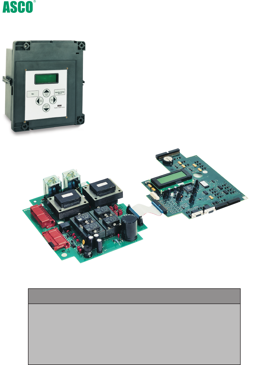
The 7000 SerieS Microprocessor Based Controller is used with all sizes of Power
Transfer Switches from 30 through 4000 Amperes. It represents the most advanced
digital controller in the industry and includes, as standard, all of the voltage,
frequency, control, timing and diagnostic functions required for most emergency
and standby power applications.
Because of severe voltage transients frequently encountered with industrial
distribution systems, the microprocessor logic board is separated and isolated from
the power board as shown below. This improves electrical noise immunity perfor-
mance and helps assure compliance with the rigorous transient suppression stan-
dards highlighted below.
10
Fig.15: Microprocessor Power and Logic PC Boards.
Fig. 14: 7000 SerieS
Microprocessor Controller.
7000 series Microprocessor Based Controller
Emission Standard - Group 1, Class A EN 55011:1991
Generic Immunity Standard, from which: EN 50082-2:1995
Electrostatic Discharge (ESD) Immunity EN 61000-4-2:1995
Radiated Electromagnetic Field Immunity ENV 50140:1993
Electrical Fast Transient (EFT) Immunity EN 61000-4-4:1995
Surge Transient Immunity EN 61000-4-5:1995
Conducted Radio-Frequency Field Immunity EN 61000-4-6:1996
Voltage Dips, Interruptions and Variations Immunity EN 61000-4-11:1994
7000 series Microprocessor Controller

Voltage and Frequency Sensing
• 3-Phase under and over voltage settings on normal
and emergency sources.
• Under and over frequency settings on normal and
emergency.
• True RMS Voltage Sensing with +/- 1% accuracy;
Frequency Sensing Accuracy is +/- 0.2%.
• Selectable settings: single or three phase voltage
sensing on normal and emergency; 50 or 60Hz.
• Phase sequence sensing for phase sensitive loads.
• Voltage unbalance detection between phases.
Status and Control Features
• Output contact (N/O or N/C) for engine-start signals.
• Selection between “commit/no-commit” on transfer
to emergency after engine start and normal restores
before transfer.
• Advanced inphase algorithm which automatically
measures the frequency difference between the two sources
and initiates transfer at appropriate phase angles to mini-
mize disturbances when transferring motor loads.
• Event log displays 99 logged events with the time and
date of the event, event type and event reason.
• Output signals for remote indication of normal and emer-
gency source acceptability
• Statistical ATS/System monitoring data screens which provide:
• Total number of ATS transfers.
• Number of ATS transfers caused by power source failure.
• Total number of days ATS has been in operation.
• Total number of hours that the normal and emergency
sources have been available.
Time Delays
• Engine start time delay - delays engine starting signal to
override momentary normal source outages - adjustable
0 to 6 seconds.
• Transfer to emergency time delay - adjustable 0 to 60
minutes.
• Emergency source stabilization time delay to ignore
momentary transients during initial generator set
loading - adjustable 0 to 6 seconds.
• Retransfer to normal time delay with two settings:
• Power failure mode - 0 to 60 minutes.
• Test mode - 0 to 10 hours.
• Unloaded running time delay for engine cooldown -
adjustable 0 to 60 minutes.
• Pre and post transfer signal time delay for selective
load disconnect with a programmable bypass on source
failures - adjustable 0 to 5 minutes. This signal can be
used to drive a customer furnished relay, or for (2) sets of
double throw contacts rated 3 amps at 480 volts AC, spec-
ify ASCO optional accessory 31Z.
• Fully programmable engine exerciser with seven
independent routines to exercise the engine generator,
with or without loads, on a daily, weekly, bi-weekly or
monthly basis.
• Contains all alarm signals, logic and time delays for
use with closed transition switches.
• In synch time delay - 0 to 3 seconds.
• Failure to synchronize - 1 to 5 minutes.
• Extended parallel - 0.1 to 1.0 seconds.
• Delayed transition load disconnect time delay -
adjustable 0 to 5 minutes.
11
7000 series Microprocessor Controller
Features
• Digital microprocessor.
•
Touch pad programming of features and settings
without the need for meters, or variable power supplies.
• Sixteen (16) selectable operating voltages available in a
single Controller.
• On-board diagnostics provide control panel and ATS sta-
tus information to analyze system performance.
• Displays and counts down active timing functions.
• Selectable multi-language display
(English, German, Portuguese, Spanish, or French. For
others contact ASCO).
• Password protection to prevent unauthorized tampering
of settings.
• Remote monitoring and control with ASCO
POWERQUEST® communications
products. Specify optional accessory 72E.
• Load shed option for bus optimization applications.
Specify optional accessory 30B.
• Historical event log
• Statistical ATS systems monitoring information
12
The 7000 SerieS microprocessor controller is a Power Control Center which
allows the user to easily access detailed information on: system status; power
source parameters; voltage, frequency and time delay settings; optional
feature settings; historical event log; and system diagnostics. A four line,
(20) character LCD has a backlit display which enables easy viewing under all
conditions. The user can navigate through all screens using only six buttons,
which also allows selection of: (18) different source parameter settings; (16)
standard time delays; (12) standard feature settings; up to seven independent
engine exercise routines; and even the language (English, German, Spanish,
French, etc.) which appears on the display.
Since the Power Control Center must be visible and operable through
the enclosure door, it has been qualified for use in industrial and outdoor
applications. This includes installation in Type 3R (outdoor/rainproof),
4 (weatherproof) and 12 (indoor/industrial) enclosures. For applications with
regular exposure to direct sunlight a double door for UV protection is recom-
mended.
7000 series Power Control Center
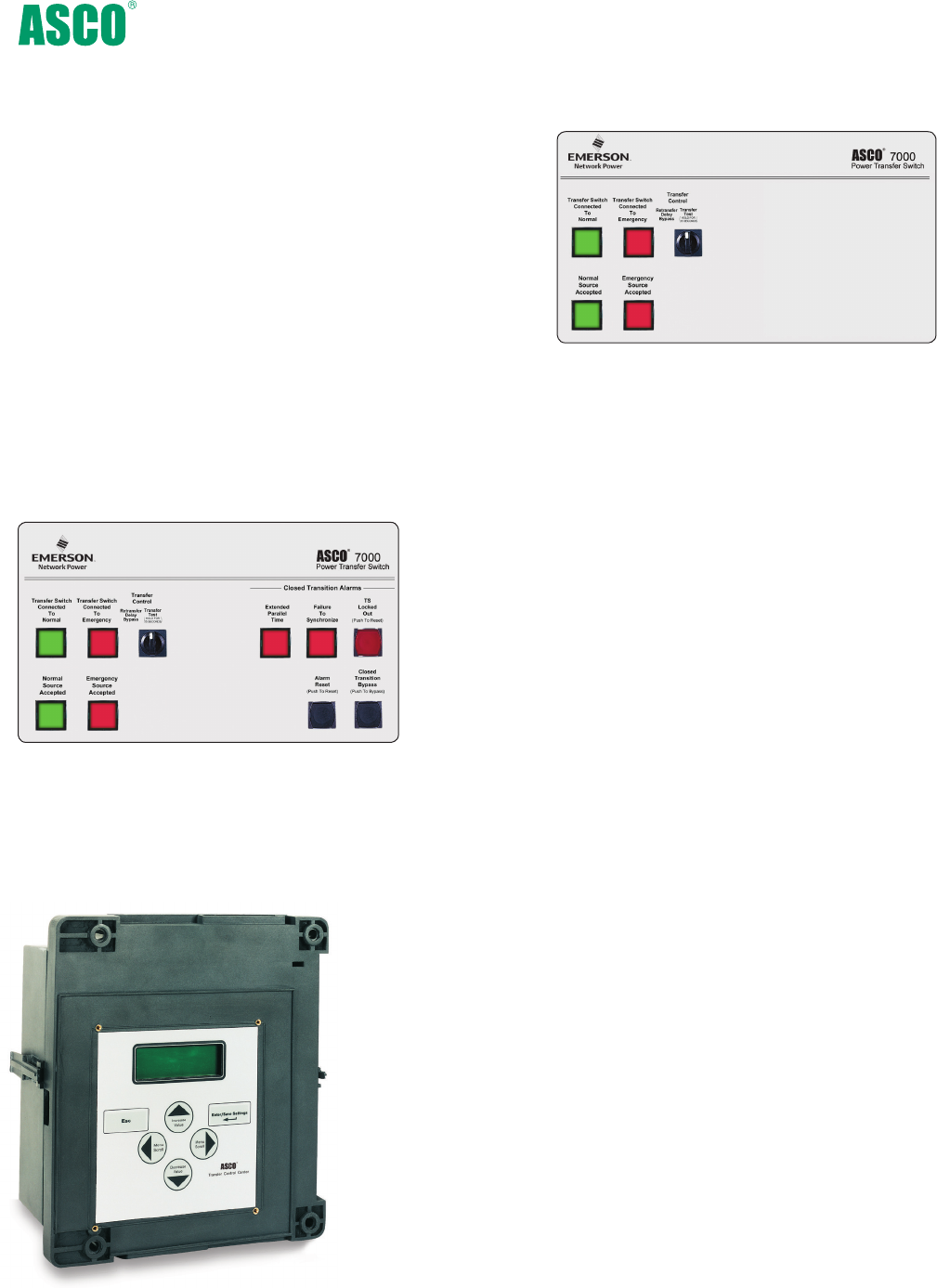
Control Switches and Indicating Lights for Conventional 2-Position Switches
Control Switches and Indicating Lights for Closed Transition Switches
Fig. 16: 7000 SerieS User Controls and Indicators.
Fig. 18: 7000 SerieS
Power Control Center.
Fig. 17: 7000 SerieS User Controls and Indicators.
• Switch position indicating lights (16 mm, industrial grade LEDs).
• Source acceptability indicating lights with true indication of the
acceptability of each source, as determined by the voltage, frequency,
voltage unbalance, and phase sequence settings of the control panel
(16mm, industrial grade LEDs).
• Three position (16mm, industrial grade type) selector switch:
• Automatic: Normal maintained position.
• Test: Momentary position to simulate normal source failure for
system test function.
• Reset Delay Bypass: Momentary position to bypass transfer and
re-transfer time delay.
• Extended Parallel Time - Provides visual indication when the
pre-set extended parallel time has been exceeded. The controls
automatically open the emergency or normal main contacts.
Separate contact also available to shunt trip external breaker.
• Failure To Synchronize - Visually displays a failure to synchronize
alarm if the time delay settings is exceeded, during closed
transition transfer operation.
• TS Locked Out - Prevents transfer in either direction if the
extended parallel time is exceeded.
• Alarm Reset - Resets extended parallel and failure to
synchronize alarms.
• Closed Transition Bypass - Pushbutton allows transfer between
sources in an open transition mode.
7000 series User Controls and Indicators
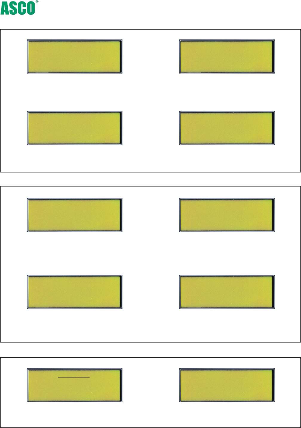
Normal Source
Vab=480V....................ABC
Vbc=480V.........Vunbal=1%
Vca=480V................60.0Hz
P1..................Engine.Exerciser
Enable:.....Yes....WLoad:....Yes
Start:19h30. ALL MON
Run.Time:...............2h15min
16.AUG02/95..........13h10:17
Eng.Start...............NormFail.
15.AUG02/95...........13h10:25
Xfer.N>E................................
Normal OK
TD.Engine.Cooldown:
4min15s
Normal OK
Load on Normal
Normal Voltage
Dropout.............85%.408V
Pickup...............90%.432V
O.V. Trip.........110%.528V
Displays voltage for each phase, frequency,
phase rotation and voltage unbalance for both
normal and emergency sources.
Provides voltage and frequency setting values for
normal and emergency sources. Voltage pick-up,
dropout and trip settings are set in percentage of nominal
voltage and are also displayed in rms voltage values.
Seven independent programs, load/no load
selection, flexible run times and daily, weekly,
bi-weekly and monthly exercise routines.
Active time delay status displays time
remaining until next control event.
TD N>E Xfer Signal
Bypass if N Fail: No
Pre Xfer: 0 min 20S
Post Xfer: 0 min 20S
Provides direct reading display for setting time delays.
Displays system status in clear, concise language.
Message shown indicates normal source is acceptable
and the load is connected to the normal source.
Displays detailed information for last 99 events,
including time of occurrence, length of event,
date and reason for event.
ATS Statistics
ATS Total Xfers: 46
SRC Fail Tot Xfers: 20
Days Energized: 36.5
Instant availability of statistical information on total number of
ATS transfers, number of transfers caused by power failures and
total days controller has been energized, plus more.
13
Source Status
Time Delay Status
Voltage and Frequency Settings Time Delay Settings
Engine Exerciser
Historical Event Log
System Status
ATS Statistics
Emerg OK
Waiting for In-Sync
-45o 0.02Hz
Displays the relative phase angle between
sources and frequency differential to indicate
the controller is awaiting an inphase condition.
Shed Load
Direction: From E
Inphase: No TD/0.25
Standard features can be activated with the keypad. As an
example, when enabled, the “shed load” option causes the
transfer switch to transfer the load off of the specified source.
If desired, the load shed transfer can be made inphase.
Inphase Transfer Mode
Feature Settings
Status
Settings
Data Logging
7000 series Power Control Center Screens

14
Time Delays
2C Provides an extended time delay on engine starting.
The standard feature one time delay is adjustable
from zero to six seconds. Accessory 2C allows this
time delay to be adjustable from zero to sixty minutes
in one second intervals factory set at five minutes.
1G Similar to accessory 2C except using 24 volt DC
external input signal. 7000 SerieS controller remains
active when both power sources are de-energized*
1GB Same as accessory 1G except using 120 volt AC
external input*
* add suffix 1 to include external power to power manager or
power meter when applicable
Manual Controls for Automatic
Transfer Switches
6C Reset switch for manual retransfer to normal with
automatic retransfer in the event of emergency
source failure.
6D Selector switch for automatic/manual retransfer to
normal. Automatic bypass if emergency fails.
Indicators
14A/14B Additional auxiliary contact sets to indicate switch
position. Two sets are standard. Specify total num-
ber of sets if more are required.
18B Two-pole, double-throw contacts operate when
emergency source voltage is present at transfer
switch terminals.
18G Two-pole, double-throw contacts operate when normal
source voltage is present at transfer switch terminals.
99 “Push-to-Test” feature on all pilot light indicators.
Customer Control Circuits
30A Load-shedding circuit initiated by opening of a
customer-supplied contact.
30B* Load-shedding circuit initiated by removal of
customer-supplied control voltage. *(Specify voltage).
31Z Selective load disconnect control contacts (two
provided) which operate with time delay prior to and/
or after load transfer and retransfer.
43R Terminal block for all customer control connections
on 30-150 amp only (standard on all other sizes).
Neutral Conductor Options
• Solid neutral, with fully-rated terminals. (AL-CU) UL Listed.
• Conventional neutral switching pole.
• Overlapping neutral transfer contacts. Allows for proper
ground-fault sensing and avoids generator voltage
transients during transfer.
Note: Specify neutral option in catalog number, see page 22 for instructions.
Extension Harness
37B
Six foot (6’) extension harness to increase distance between
transfer switch and control panel on open-type units.
Communications
72E 5150 Ethernet Connectivity Module offers
communication to transfer switch and metering
with embedded webpages.
72SW An Industrial Ethernet Switch mounted in the
enclosure used in conjunction with 5150
Connectivity Module (acc. 72E) metering device.
Includes 2 available Ethernet ports and 2
multimode ST Fiber connectors.
Surge Protection
ASCO Pulsar 450 rated 65KA
73AC1 Normal source protection. (3Ø, 4wire WYE)
73AC2 Emergency source protection. (3Ø, 4wire WYE)
73AC3 Load side protection. (3Ø, 4wire WYE)
Note: Other distribution voltages available (Contact ASCO).
Special Applications
45 Custom Alphanumeric nameplate mounted on the front
of the switch
111A Generator - to - Generator for Standby Applications
111B Generator - to - Generator for Prime Power
Applications
125 Seismic Certification to the requirements of the
international building code for electrical equipment
131 Certification of compliance with the American
Recovery & Reinvestment ACT (Buy American Provision)
- Must be specified at time of order placement
Bypass-Isolation Switch Options
14A1 Auxiliary contact to close in “Bypass to Normal”
position.
14B1
Auxiliary contact to close in “Bypass to Emergency” position.
14T Auxiliary contact to close when transfer switch is in
“Automatic” position.
14U Auxiliary contact to close when transfer switch is in
“Isolate” position.
14V Auxiliary; contact to close when transfer switch is in
“Test” position.
82C Automatic shutters for bus isolation when transfer
switch is withdrawn. (see page 6 for details)
82E LED Bypass status indicator, optional on G frame
1600A-4000A only. Standard for all other size switches
Note: An externally operable quick-make, quick-break (QMQB), manual handle is avail-
able on some 7000 SerieS product configurations. (Consult ASCO for guidance.)
7000 series Optional Accessories
15
Optional Configurations and
Connection Arrangements
Connected To: 5210 5220
Load Acc. 135L Acc. 85L
Normal Acc. 135L Acc. 85N
Emergency Acc. 135E Acc. 85M
Load (BPS only) N/A Acc. 85SB*
Add suffix A1 to above metering designation if neutral conductor monitoring is required
Note: Accessory 85L and 135L includes component mounting, CTs, shorting
blocks and all necessary interwiring.
*Bypass & isolation switch contacts wired to discrete Power Manager inputs.
7000 series Optional Accessories
Power Metering
• Voltage:
Line - Line: VAB, VBC, VCA, VAVERAGE
Line - Neutral: VAN, VBN, VCN, VAVERAGE
• Frequency: 45.0 to 66.0 Hertz
• Current: IA, IB, IC, IAVERAGE
• Unbalance %: Voltage, Amps
• Real Power: KWA, KWB, KWC, KWNET
• Reactive Power: KVARA, KVARB, KVARC, KVARNET
• Apparent Power: KVAA, KVAB, KVAC, KVANET
• Real Energy: KWHIMPORT, KWHEXPORT, KWHNET
• Reactive Energy: KVARHIMPORT, KVARHEXPORT,
KVARHNET
• Power Factor: PFA, PFB, PFC, PFNET
5220 Power Manager Data Access
• Eight digital inputs, four relay outputs.
• Input/Output 15-character, user definable screen
display for identification of input/output signals.
Communications
• Modbus RTU and TCP/IP capability
• Ethernet compatible when combined with
5150 Connectivity Module (72E).
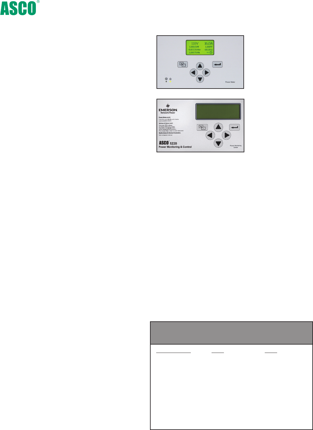
Fig. 19: ASCO 5210 SerieS
Power Meter.
Configurable Designations
• Local - A four line, 20 character LCD backlit display.
• 5220 Power Manager provides user programmable setpoints
based on twelve metering and I/O parameters. Each setpoint
allows the user to select the parameter, the trip & reset levels,
the trip & reset time delays and the alarm type or relay output
to trigger. This can be used for protective relaying and peak
shaving applications.
• 100 event data logging feature.
Integrated ATS Features
When configured on load of ATS:
• Displays ATS position.
• Displays power data as a function of ATS position
(normal/emergency).
• Accumulates energy data separately for normal and
emergency sources.
ASCO 5200 series Metering
Power Manager
The ASCO 5200 SerieS Power Meters are microprocessor
based metering devices that provides real-time measure-
ment of single and three phase power systems. The 5200
SerieS uses digital signal processing technology to measure
voltage and current per phase; real, reactive and apparent
power, and bi-directional energy. All measurements can be
viewed locally with a backlit liquid crystal display and/or
displayed remotely with ASCO POWERQUEST ® products.
Direct voltage input for systems up to 600 Volts AC
can be monitored without the use of external potential
transformers (PTs). Measures three phase currents and a
fourth current input is available for measuring current
in the neutral conductor. The 5200 SerieS includes one
discrete input for transfer switch position.
Note: The ASCO Power Manager is also available as a separate unit for monitoring electrical parameters anywhere in the power distribution system.
Fig. 20: ASCO 5220 SerieS
Power Manager.
16
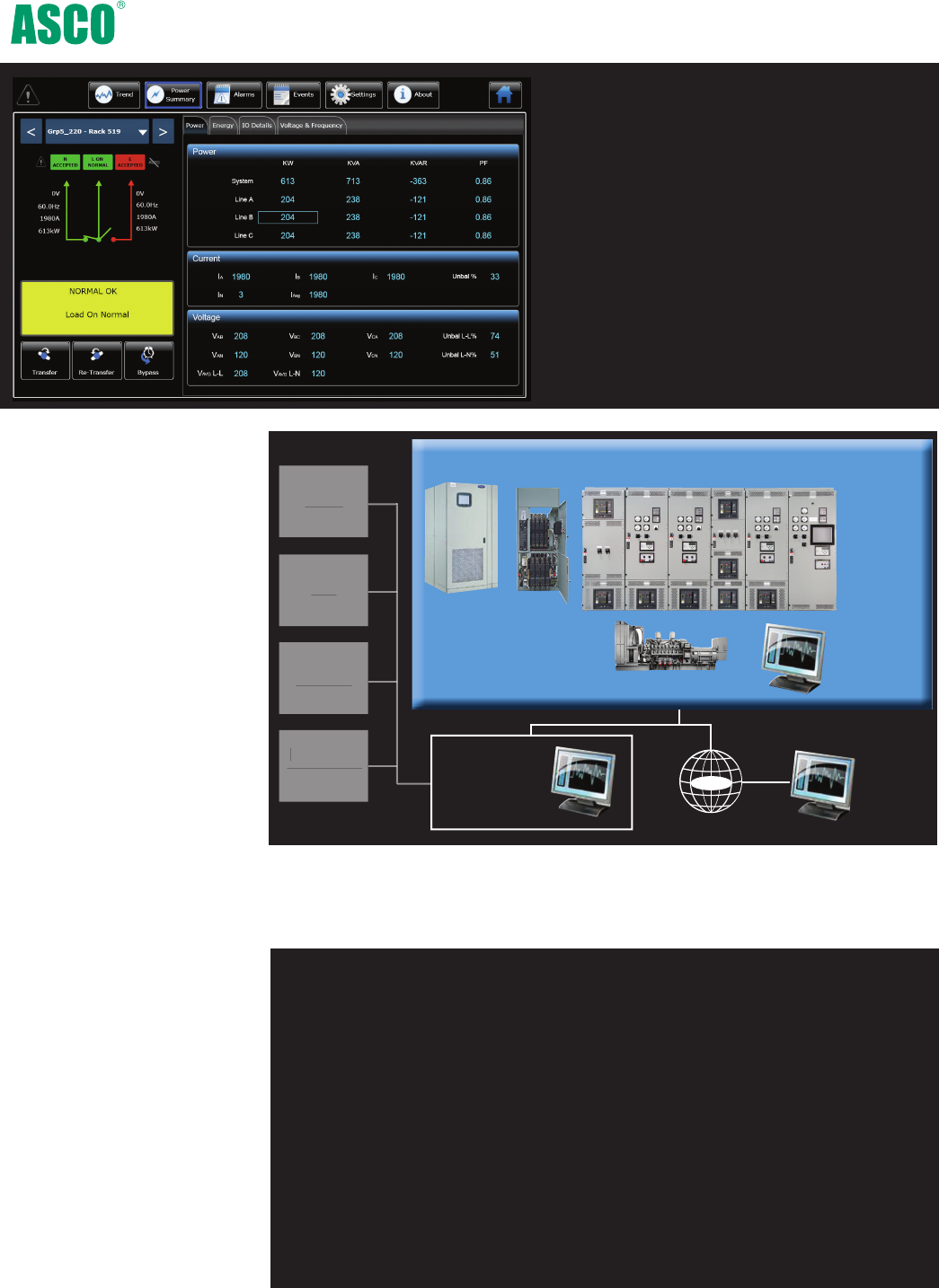
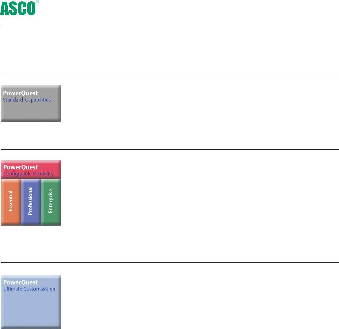
PowerQuest® Power Monitoring and Control Systems
FULFILL YOUR NEED
Drill down for a closer look - Each transfer
switch, generator, breaker and any other
power equipment has its own dedicated
screens.
It’s the new ASCO PowerQuest®
Power Monitoring and Control
family.
The PowerQuest® family is the
most comprehensive communi-
cation, monitoring and control
solution ever offered by ASCO.
It empowers you. It fulfills your
need to test, manage loads,
optimize the bus bar, remotely
monitor and otherwise be aware
of the status of your facility’s
utility source and on-site power.
You have both the Power to
Know and the Power to Do.
Whether you require stan-
dard monitoring and control,
or a comprehensive Critical
Power Management System,
PowerQuest can satisfy your
needs.
Hardware. Software. Installation
and testing. Service. And
upgrades and technology
refreshes. A truly complete solu-
tion for all your communication,
monitoring and control needs.
The following PowerQuest®
pages can help you determine—
easily— the type of PowerQuest
system you need for your ASCO
power switching and controls,
and third-party equipment.
U
P
S
Securit
y
Fir
e
Alarm
Mon
i
tor
i
n
g
HVA
C
Critical Power Management System (CPMS)
Static
Transfer
Switches
Transfer
Switches
Paralleling
Control
Switchgear
Generators
CPMS
Display
Terminal
Remote
Display
Terminal
Building
Management
System (BMS)
Internet
PowerQuest® provides monitoring, alarming and control of Critical Power
Management Systems, which comprise transfer switches, paralleling control
switchgear, gensets, circuit breakers, distribution and other gear. It also
integrates with building management systems.
BE EMPOWERED
PowerQuest® can enable you to:
• Monitor and control power transfer switches, paralleling control
switchgear, gensets, breakers, bus bars and other equipment
• Monitor normal and emergency voltages and frequency and their settings
• Know transfer switch position and source availability
• Transfer and re-transfer loads for system testing
• View and adjust transfer switch time-delay settings
• Know each transfer switch’s rating and identification
• Receive automatic alerts on system operation via e-mail, pager,
or selected system alarms
• View current, power and power factor
• View transfer switch event log and know the transfer switch test schedule

17
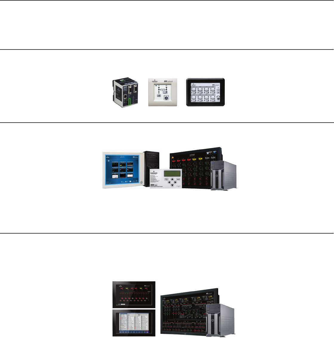
7000 series PowerQuest® Monitoring & Control Components
An ASCO 5150 Connectivity Module (left) pro-
vides 100 Mbps Ethernet Connectivity for ASCO
Transfer Switches and Power Meters and includes
AES 128-bit Encryption, as per NIST, for enhanced
security.
The ASCO 5160 Remote Connectivity Unit (RCU)
(right) provides 10 Ethernet and Dual-Fiber Optic
connections in a NEMA 3R enclosure.
ASCO 5210 (left) and 5220 (right) Power
Meters measure, displays and provides single-
or 3-phase Energy and Power information with
Ethernet via the ASCO 5150 Communication
Module.
5150, 5160
Connectivity
Modules
5210, 5220
Power
Meters
5310, 5350
Annunciators
ASCO 5310(left) and 5350(right) ATS Remote
Annunciators provide distributed monitoring of
transfer switch position and source availability as
well as transfer test and re-transfer control.
Building-block components can be configured easily to provide
exactly the degree of monitoring, control and communication you
want for your on-site power system.
ASCO 5400 Series Power Quality Meters
The ASCO Power Quality Meters provide intelli-
gent power analysis, energy measurement and
event recording for critical and sensitive loads.
Its unique continuous waveform and harmonic
recording capabilities ensure all events are cap-
tured, improves response time, and helps identify
corrective action to power quality related issues.
5010 Remote
Display Unit,(left)
5490 Critical
Power Quality
Meter, (right)
Enterprise
Critical Power
Management
System
5700 Series provide various levels of monitoring,
control and management capability of power
equipment. It seamlessly monitors ASCO trans-
fer switches as well as generators, breakers,
paralleling bus, panel boards and other power
equipment via a 5221 PMU. It consists of serv-
ers and touch screen interfaces.
18
7000 series PowerQuest Monitoring & Control
The Power To Know
Selecting the system that provides your level of need-to-know
information and control...
You Need... Your Application Is... Desired Capabilities
Basic monitoring, remote
alarming and control, or, if
you simply want to know
transfer switch status or per-
form monthly transfer testing
Residential, light commercial
and retail establishments
Local or remote, floor-level
monitoring and control, or as
part of a larger, facility-wide
monitoring and control sys-
tem
A ‘specify-your-own’ Critical
Power Management System
(CPMS) that includes gensets,
circuit breakers, and reports
on energy, trending, power
demand, bypass status,
diagnostics, alarming, and
component-level monitoring
and control.
Commercial, retail,
telecom, agriculture,
municipal, such as waste
water treatment, light indus-
trial plants, educational cam-
puses and healthcare facilities
requiring distributed power
and load management
Local, floor-level, or facil-
ity-level monitoring and
control; 5700 systems can be
configured in three capability
levels:
• Essential (single building)
• Professional (multiple
buildings, single campus)
• Enterprise (multiple
campuses)
A Critical Power Management
System providing sys-
tem-wide monitoring, alarm-
ing and control of transfer
switches, paralleling control
switchgear, gensets and
distribution, both on and off
site; also integrates PLCs,
building management sys-
tems and on-site, simulator
training. Power quality and a
range of other information is
provided.
Regional and global networks
of data centers, financial
institutions, Web hosting
companies and healthcare
campuses that operate
expansive and sophisticated
on-site power systems that
are essential for providing
24/7 power reliability
Local floor-level monitoring
and control, and remote
system-wide monitoring and
control seamlessly integrated
with building management
systems; communication
paths can be Ethernet, Web-
based PC’s and monitors;
simulator training that mim-
ics the live system allows
conducting ‘what if’ scenar-
ios, without risking system
operation.
19
Identifies the ASCO products and components required to provide the functionality you need.
Products Required Components Functionality
ASCO Series 185 and Series
300 Automatic Transfer
Switches
Connectivity Modules and Annunciators Locally monitor switch position,
source availability and the status
of on-site power system devic-
es via customized Web page.
Initiate tests and push-button
remote transfer. Aural, visual
alarms.
ASCO 4000 Series and 7000
Series Automatic Transfer
Switches, including 7000
Series Bypass-Isolation
Standard components, plus Power Control System
Management and Operator Interface Terminals
Monitor voltage and phase
currents. Capture/store more
data points. Display data on
screen up to 42” inches.
Interface with power control
system, BMS. Integrate with
Group 5 Controller. Get email
alerts. For single buildings,
single campuses and global
facilities. Provides Energy,
Alarm, and Outage/Test Reports
that can be used to fulfill Joint
Commission Requirements.
ASCO 7000 Series Automatic
Transfer Switches, including
Bypass-Isolation and 7000
Series Generator Paralleling
Control Switchgear
Standard and Configurable components, plus
higher performance Power Control System and
Data Management Screens, and an on-site
Simulator Training System
Interact fully with incoming
utility service boards, mission
critical paralleling gear, transfer
switches, UPSs, STSs and PDUs...
and interface with Building
Management Systems. Capture,
store and analyze quantities of
data to optimize on-site power
operation. Use your display
devices and/or ASCO 42” LCD
screen. Highly customize your
GUI with sophisticated HMI/
SCADA software.
20
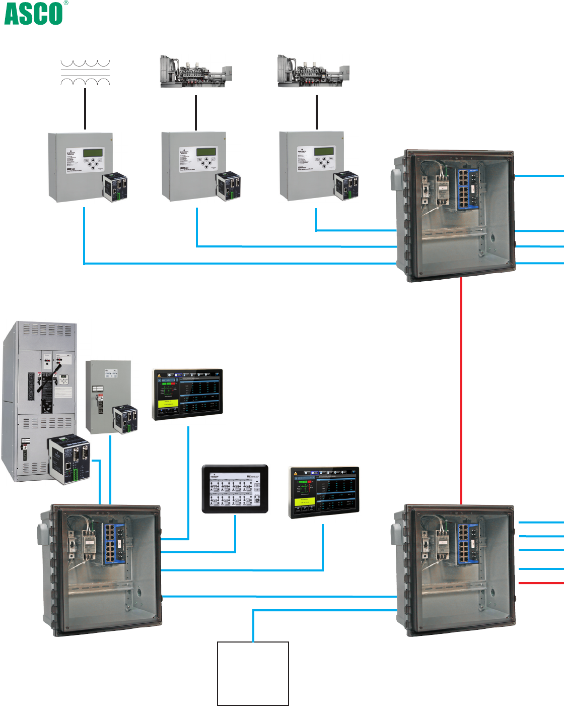
PowerQuest® 5700 Critical Power Management System
5221
Power
Manager
Units
24 VDC
QTY 4, 14 Awg
3P Volts/Amps
Utility Generator Generator
24 VDC
QTY 8, 14 Awg
3P Volts/Amps
24 VDC
QTY 8, 14 Awg
3P Volts/Amps
5160 RCU
24VDC or 120 VAC
(Requires UPS)
7000 ATS
300 ATS
Tx/Rx (pair of Fiber)
24VDC
24VDC
5350 Annunciator
To RCU and
Additional
Networked
Devices
19” 5702 Operator
Touch Panel
(up to 100 with
5790 Server)
19” 5702 Operator
Touch Panel
(up to 100 with
5790 Server)
5160 RCU
24VDC or 120 VAC
(Requires UPS)
5160 RCU
24VDC or 120 VAC
(Requires UPS)
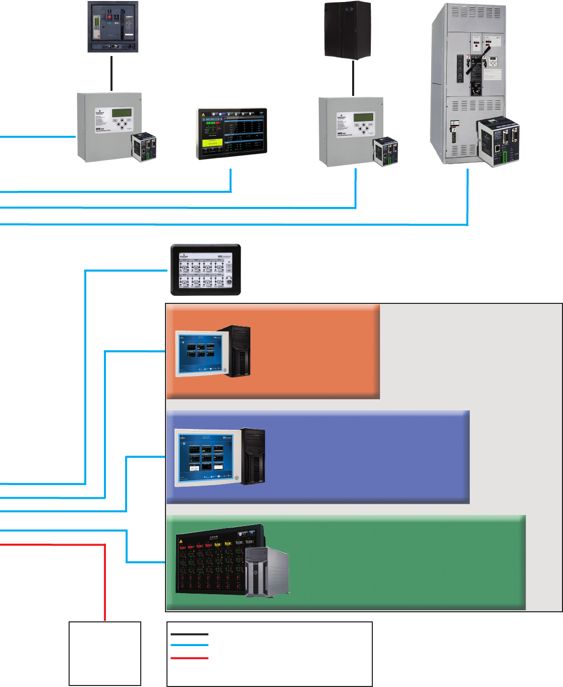
21
Breaker
24 VDC
QTY 4, 14 Awg
3P Volts/Amps
UPS/Distribution
24 VDC
QTY 8, 14 Awg
3P Volts/Amps
7000 ATS
5350 Annunciator
ATS Status Annunciation
Transfer Test
Supports 8 ATS’s
24VDC/120VAC/220VAC
To RCU and
Additional
Networked
Devices
5710 CPMS Server
• Drives 3 Remote 5702
Panels
•Supports 32 Power Devices
•Basic Monitoring and Control
•Standard Performance
5750 CPMS Server
Essential Features PLUS:
• Drives 10 Remote
5702 Panels
• Supports 64 Power
Devices
• Historical Trending
• 5 Reporting Packages
• BMS Modbus Support
•Remote E-Mail
Alarming
5790 CPMS Server
Professional Features
PLUS:
•Drives 100 5702 Touch
Panels
•Redundant Power
•Redundant Storage
•Redundant Processors
•Ultimate Performance
•128 Power Devices
•Expanded Storage
•Inter-facility Messaging
AWG Wire Size and Distance by others
Category 6 Ethernet (300 Feet Max)
Multi-Mode Fiber, 1300nm, 50/125um,
ST Connectors (6500) Feet Max
5700 CPMS Servers
Note - Select One Server to install
in Centralized Office
50° to 95°F (10°C to 35°C)
NOTES -
1. This Drawing is to be used as a Model only;
Actual network architecture will depend on
equipment placement, cable length and type.
2. 5700 Series Products Operating Temperature is
50° to 95°F (10°C to 35°C) For altitudes above 2950 feet,
the maximum operating temperature is
derated 1°F/550 ft.
19” 5702 Operator
Touch Panel
(up to 100 with
5790 Server)
+ + + + + +
TSA A 3 400 N5X C
22
To order an ASCO 7000 series Power Transfer Switch, complete the following catalog number:
The Example Catalog Number above is 7ATSA3400N5XC
(X is used to specify optional accessories).
7
*Notes: Conventional switch neutral is provided on closed and delayed
transition transfer products when specified.
Amperes Voltage
Code
Grp
Code
Enclosure
Neutral
Code*
Product Phase
Poles
115
120
208
220
230
240
380
400
415
440
460
480
550
575
600
TS
TB
CTS
CTB
DTS
DTB
2
3
A
N
M
Automatic
Non-
Automatic
Manually
Operated
5
5X-
optional
accesso-
ries
---
C
F**
G
H
L
M
N
P
Q
R
---
A
B
C
Conventional
2-Position
Open
Transition
Bypass
Closed
Transition
Closed
Transition
Bypass
Delayed
Transition
Delayed
Transition
Bypass
No Neutral
Solid Neutral
Switched
Neutral
Overlapping
Neutral
A
B
C
D
E
F
H
J
K
L
M
N
P
Q
R
No enclosure
Type 1 enclosure
Type 3R
enclosure
Type 4 enclosure
Type 4X
enclosure
(stainless steel)
Type 12
enclosure
Type 3R secure
double door
Type 4 secure
double door
Type 4X secure
double door
Type 12 secure
double door
Type 3RX secure
double door
(Stainless Steel)
Transfer Switch Configurations
7A TS, 7N TS, 7A DTS, 7A CTS, 7N DTS, 7N CTS
Transfer/Bypass Configurations
7A TB, 7N TB, 7A DTB, 7A CTB, 7N DTB, 7N CTB
Sizes of UL-Listed Solderless Screw-Type
Terminals for External Power Connections
Notes: 1. Unit is designed for top cable entry of emergency and load and bottom entry
of normal. Optionally, the switch may be supplied with reverse source and/or
bottom entry load, when specified.
2. All main terminals are rear connected.
Switch Rating
amps
Max # of Conductors
per Terminal
Range of AL-CU
Conductor Sizes
One
One
Two
Two
Four
Six
Twelve
#14 to 4/0 AWG
#4 AWG to 600 MCM
#1/0 AWG to 600 MCM
#1/0 AWG to 600 MCM
#1/0 AWG to 600 MCM
#1/0 AWG to 250 MCM
#1/0 AWG to 600 MCM
30 -2303
600
800-12001
1600-20002
2600, 30002
40002
150*, 260, 400
*150 for CTS and DTS Only
Sizes of UL-Listed Solderless Screw-Type
Terminal for Power Connections
Switch Rating
amps
Max # of Conductors
per Terminal
Range of AL-CU
Conductor Sizes
One
Two
Two
Four
Six
Ten
Twelve
# 1/0 AWG to 250 MCM
# 4 AWG to 600 MCM
# 2 AWG to 600 MCM
# 2 AWG to 600 MCM
# 2 AWG to 600 MCM
# 1/0 AWG to 600 MCM
# 1/0 AWG to 600 MCM
150, 200, 230
260,400
6004
800,1000,12004
1600-20004
2600, 30004
40004
3. 200 and 230 amp rating for copper conductors only for transfer switch
configurations only.
4. All main terminals are rear connected. A front connected version is
available in 600 and 1200 amp ratings only with top cable entry only.
See pages 25-27 for dimensional data and additional information.
5.Type 304 stainless steel standard. Specify 316 ST. Steel for installations
subject to salt water and corrosive environments
7000 series Ordering Information
30
70
100
150
200
230
260
400
600
800
1000
1200
1600
2000
2600
3000
4000
*
*
Twelve #2/0 AWG to 600 MCM
**Type 3R enclosures are not suitable for installations conducive
to windblown snow or rain conditions.

23
2-Position Transfer Switching 7A TS, 7N TS (Non-Bypass)
Notes:
1. Enclosures are free-standing
with removable top, sides, and
back.
2. Consult ASCO for dimensions on
enclosures other than UL type 1.
3. Order accessory 40MY for
1600A and 40NY for 2000A F/C
design.
7000 series Designed to Fit Anywhere*
2-Position Transfer Switching 7A TS, 7N TS
Shipping Weights
Depth
inches (mm)
Height
inches (mm)
Width
inches (mm)
Poles
Switch Rating
Amps
Enclosed UL Type 1 2
30, 70, 100, 125, 150, 200, 230 2, 3 or 3 with neutral A/B/C 18 (457) 48 (1219) 13 (330)
260, 400 2, 3 or 3 with neutral A/B/C 24 (610) 56 (1422) 14 (356)
600 2, 3 or 3 with neutral A/B/C 24 (610) 63 (1600) 17 (432)
800, 1000 2, 3 or 3 with neutral A/B/C 34 (864) 72 (1829) 20 (508)
1200 2, 3 or 3 with neutral A/B/C 38 (965) 87 (2210) 23 (584)
1600, 20001 2, 3 or 3 with neutral A/B/C 38 (965) 91 (2311) 48 (1219)
1600, 20003 (front connected) 2, 3 or 3 with neutral A/B/C 38 (965) 87 (2210) 23 (584)
2600, 30001 2, 3 or 3 with neutral A/B/C 38 (965) 91 (2311) 60 (1524)
40001 2, 3 or 3 with neutral A/C 60 (1524)
91 (2311)
72 (1829)
Open Configuration
30, 70, 100, 125,150, 200, 230 2, 3 or 3 with neutral B/C 10-1/4 (260) 10-1/4 (260) 5-1/2 (140)
260, 400 2, 3 or 3 with neutral B/C 18-1/2 (470) 25 (635) 8 (203)
600 2, 3 or 3 with neutral B/C 19 (483) 30 (762) 9-7/8 (251)
800, 1000, 1200 2, 3 or 3 with neutral B/C 27 (686) 31 (787) 12-7/8 (327)
1600, 2000 2, 3 or 3 with neutral B/C 33-1/4 (845) 28 (711) 26-1/4 (667)
2600, 3000 2, 3 or 3 with neutral B/C 33-1/4 (845) 28 (711) 30-3/4 (781)
4000 2, 3 or 3 with neutral C
60 (1524)
70 (1778) 53 (1272)
30, 70, 100, 125 2 125 (57) 45(20)
30, 70, 100, 125 2 125 (57) 45(20)
30, 70, 100, 125 3 with B/C 130 (59) 50(23)
150, 200, 230 2 125 (57) 70(32)
150, 200, 230 2 125 (57) 70(32)
150, 200, 230 3 with B/C 130 (59) 75(34)
260, 400 2 250(114) 135(61)
260, 400 3 255(116) 140(64)
260, 400 3 with B/C 270(123) 150(68)
600 2 320(145) 210(95)
600 3 325(148) 210(95)
600 3 with B/C 340(154) 220(100)
800, 1000 2 480(218) 275(125)
800, 1000 3 485(220) 280(127)
800, 1000 3 with B/C 500(227) 290 (132)
1200 2 670(304) 305 (138)
1200 3 675(306) 310 (141)
1200 3 with B/C 690 (313) 320 (145)
1600, 2000 2 1280(581) 520 (236)
1600, 2000 3 1300(590) 520 (236)
1600, 2000 3 with B/C 1320(599) 540 (245)
2600, 3000 2 1440(654) 620 (281)
2600, 3000 3 1460(663) 620 (281)
2600, 3000 3 with B/C 1480(672) 640 (291)
4000 2 2690(1221) 1620 (735)
4000 3 2710(1230) 1640 (745)
4000 3 with B/C 2730(1239) 1660 (754)
Open*
lb (kg)
Enclosed*
lb (kg)
Poles
Switch Rating
Amps
*All dimensions and weights
shown are approximate and
should not be used for construction
purposes. Certified dimensions can
be furnished upon request.
*All dimensions and weights
shown are approximate and
should not be used for construction
purposes. Certified dimensions can
be furnished upon request.

7000 series Designed to Fit Anywhere*
Notes:
1. Enclosures are free-
standing with removable top,
sides, and back.
2. Consult ASCO for dimen-
sions on enclosures other
than UL type 1.
3. Order accessory 40MY for
1600A and 40NY for 2000A
front connected design.
Closed Transition and Delayed Transition Transfer Switching
7A DTS, 7A CTS, 7N DTS, 7N CTS
Shipping Weights
Notes:
1. Open weights include
transfer switch and control
panel. 1200-4000 amp
enclosures require ventilation
openings, refer to drawings
for details. Export shipments
may require a wooden box,
contact ASCO for weights and
dimensions.
24
Depth
inches (mm)
Height
inches (mm)
Width
inches (mm)
Poles
Switch Rating
Amps
Enclosed UL Type 1 2
150, 260, 400 2, 3 or 3 with neutral A/B 24 (610) 56 (1422) 14 (356)
600 2, 3 or 3 with neutral A/B 24(610) 63 (1600) 17(432)
800, 1000 2, 3 or 3 with neutral A/B 34 (864) 72 (1829) 20 (508)
1200 2, 3 or 3 with neutral A/B 38 (965) 87 (2210) 23 (584)
1600, 20001 2, 3 or 3 with neutral A/B 38 (965) 91 (2311) 48 (1219)
1600, 20003 (front connected) 2, 3 or 3 with neutral A/B 38 (965) 87 (2210) 23 (584)
30001 2, 3 or 3 with neutral A/B 38 (965) 91 (2311) 60 (1524)
40001 2, 3 or 3 with neutral A/C
60 (1524)
91 (2311) 72 (1829)
Open Configuration
150, 260, 400 2, 3 or 3 with neutral B 18-1/2 (470) 25 (635) 8 (203)
600 2, 3 or 3 with neutral B 19 (483) 30 (762) 9-7/8 (251)
800, 1000, 1200 2, 3 or 3 with neutral B 27 (686) 31 (787) 12-7/8 (327)
1600, 2000 2, 3 or 3 with neutral B 33-1/4 (845) 28 (711) 26-1/4 (667)
2600, 3000 2, 3 or 3 with neutral B 33-1/4 (845) 28 (711) 30-3/4 (781)
4000 2, 3 or 3 with neutral C 60 (1524) 70 (1778) 53 (1272)
Open*
lb (kg)
Enclosed*
lb (kg)
Poles
Switch Rating
Amps
150, 260, 400 2 275 (125) 160 (73)
150, 260, 400 3 280 (127) 165 (75)
150, 260, 400 3 with B 295 (134) 175 (79)
600 2 345 (157) 235 (107)
600 3 350 (159) 235 (107)
600 3 with B 365 (166) 245 (111)
800, 1000 2 505 (229) 300 (136)
800, 1000 3 510 (232) 305 (138)
800, 1000 3 with B 525 (238) 315 (143)
1200 2 695 (316) 330 (150)
1200 3 700 (318) 335 (152)
1200 3 with B 715 (325) 345 (157)
1600, 2000 2 1305 (592) 545 (247)
1600, 2000 3 1325 (602) 545 (247)
1600, 2000 3 with B 1345 (611) 565 (257)
2600, 3000 2 1465 (665) 645 (293)
2600, 3000 3 1485 (674) 645 (293)
2600, 3000 3 with B 1505 (683) 665 (302)
4000 2 2715 (1233) 1645 (747)
4000 3 2735 (1242) 1665 (756)
4000 3 with B 2755 (1251) 1685 (765)
Closed Transition and Delayed Transition Transfer Switching
7A DTS, 7A CTS, 7N DTS, 7N CTS
*All dimensions and weights
shown are approximate and
should not be used for
construction purposes.
Certified dimensions can be
furnished upon request.
*All dimensions and weights
shown are approximate and
should not be used for
construction purposes.
Certified dimensions can be
furnished upon request.
7000 series Designed to Fit Anywhere*
Automatic Transfer Bypass-Isolation Switching
with Transfer Switch Engaged 7A TB, 7N TB
Automatic Transfer Bypass-Isolation Switching
with Transfer Switch Engaged 7A TB, 7N TB
Open*
lb (kg)
Enclosed*
lb (kg)
Poles
Switch Rating
amps
150, 200, 230, 260, 400, 600 2 990 (449) Contact ASCO
150, 200, 230, 260, 400, 600 3 1050 (477) Contact ASCO
150, 200, 230, 260, 400, 600 3 with B/C 1110 (504) Contact ASCO
800, 1000, 1200 2 1510 (686) 920 (418)
800, 1000, 1200 3 1580 (717) 990 (449)
800, 1000, 1200 3 with B/C 1650 (749) 1060 (481)
1600, 2000 2 2180 (990) 1300 (590)
1600, 2000 3 2360 (1071) 1550 (704)
1600, 2000 3 with B/C 2540 (1153) 1800 (817)
2600, 3000 3 2730 (1239) 1690 (767)
2600, 3000 3 with B/C 3360 (1525) 1980 (899)
4000 3 6300 (2860) Contact ASCO
4000 3 with B/C 6900 (3133) Contact ASCO
Shipping Weights
Notes: 1.Open weights include transfer switch, bypass-isolation switch and controller.
1600-4000 amp enclosures require ventilation openings, refer to drawings for details.
Export shipments may require a wooden box, contact ASCO for weights and dimensions.
25
*All dimensions and weights shown are approximate and should not be used for construction purposes.
Certified dimensions can be furnished upon request.
Notes: 1. Handles extend 6-1/4 inches (159mm).
2. Recommended clearance to enclosure: 3 feet (914mm) from rear, 4 feet (1219mm) from front (25 inches required for transfer switch drawout).
Side or rear access required.
3. Specify optional accessory 40J Y for 800 Amp front, 40KY for 1000 Amp, and 40LY for 1200 Amp - connected arrangement. All service and load
cables limited to top entry only.
4. Contact ASCO for details.
Depth
inches (mm)
Height
inches (mm)
Width
inches (mm)
Poles
Switch Rating
amps
Enclosed UL Type 1
150, 200, 230, 260, 4001, 600 Front Connected 2, 3 or 3 with neutral A/B/C 34 (864) 85 (2159) 28 (711)
8001, 3 Front Connected 2, 3 or 3 with neutral A/B/C 38 (965) 91 (2311) 32 (813)
1000, 1200 Front Connected 2, 3 or 3 with neutral A/B/C 38 (965) 91 (2311) 34 (864)
800, 1000, 12001, 2 Side/Rear Connected 2, 3 or 3 with neutral A/B/C 38 (965) 91 (2311) 48 (1219)
1600, 20001,2 Side/Rear Connected 2, 3 or 3 with neutral A/B/C 38 (965) 91 (2311) 60 (1524)
2600, 30001, 2 Side/Rear Connected 3 or 3 with neutral A/B/C 38 (965) 91 (2311) 72 (1829)
40001,2 Rear Connected 3 or 3 with neutral A/C 60(1524) 91 (2311) 96 (2438)
150, 200, 230, 260, 4001 Front Connected 2, 3 or 3 with neutral B/C 19-3/4 (500)4 61-1/2 (1553)4 28(711)4
600, 800, 1000, 12001, 2 Rear Connected 2, 3 or 3 with neutral B/C 38 (965) 72 (1829) 38 (965)
1600, 2000, 2600, 30001, 2 Rear Connected 2, 3 or 3 with neutral B/C 38 (965) 72 (1829) 38 (965)
40001,2 Rear Connected 3 or 3 with neutral A/C 60(1524) 91 (2311) 96 (2438)
Open Configuration
Power Connection
Configuration
*All dimensions and weights shown are approximate and should not be used for construction purposes.
Certified dimensions can be furnished upon request.
Automatic Transfer Bypass-Isolation in Closed Transition and Delayed
Transition Switching. 7A DTB6, 7A CTB, 7N DTB6, 7N CTB
Depth
inches (mm)
Automatic Transfer Bypass-Isolation in Closed Transition and Delayed
Transition Switching. 7A DTB, 7A CTB, 7N DTB, 7N CTB
Open*
lb (kg)
Enclosed*
lb (kg)
Poles
Switch Rating
amps
150, 200, 230, 260, 400, 600 2 1015 461 Contact ASCO
150, 200, 230, 260, 400, 600 3 1075 (488) Contact ASCO
150, 200, 230, 260, 400, 600 3 with A/B 1135 (515) Contact ASCO
800, 1000, 1200 2 1535 (697) 945 (429)
800, 1000, 1200 3 1605 (729) 1015 (461)
800, 1000, 1200 3 with A/B 1675 (760) 1085 (493)
1600, 2000 2 2205 (1001) 1325 (602)
1600, 2000 3 2385 (1083) 1575 (715)
1600, 2000 3 with A/B 2565 (1165) 1825 (829)
2600, 3000 3 2755 (1251) 1715 (779)
2600, 3000 3 with A/B 3385 (1537) 2005 (910)
4000 3 6325 (2872) -
4000 3 with C 6925 (3144) -
Shipping Weights
Notes: 1. Open weights include transfer switch, bypass-isolation switch and controller.
1600-4000 amp enclosures require ventilation openings, refer to drawings for details.
Export shipments may require a wooden box, contact ASCO for weights and dimensions.
7000 series Designed to Fit Anywhere*
26
*All dimensions and weights shown are approximate and should not be used for construction purposes.
Certified dimensions can be furnished upon request.
Notes: 1. Handles extend 6-1/4 inches (159mm).
2. Recommended clearance to enclosure: 3 feet (914mm) from rear, 4 feet (1219mm) from front (25 inches required for transfer switch drawout).
Side or rear access required.
3. Specify optional accessory 40J Y for 800 Amp front, 40KY for 1000 Amp, and 40LY for 1200 Amp - connected arrangement. All service and load
cables limited to top entry only.
4. Contact ASCO for details.
Depth
inches (mm)
Height
inches (mm)
Width
inches (mm)
Poles
Switch Rating
amps
Enclosed UL Type 1
150, 200, 230, 260, 4001, 600 Front Connected 2, 3 or 3 with neutral A/B/C 34 (864) 85 (2159) 28 (711)
8001, 3 Front Connected 2, 3 or 3 with neutral A/B/C 38 (965) 91 (2311) 32 (813)
1000, 1200 Front Connected 2, 3 or 3 with neutral A/B/C 38 (965) 91 (2311) 34 (864)
800, 1000, 12001, 2 Side/Rear Connected 2, 3 or 3 with neutral A/B/C 38 (965) 91 (2311) 48 (1219)
1600, 20001,2 Side/Rear Connected 2, 3 or 3 with neutral A/B/C 38 (965) 91 (2311) 60 (1524)
2600, 30001, 2 Side/Rear Connected 3 or 3 with neutral A/B/C 38 (965) 91 (2311) 72 (1829)
40001,2 Rear Connected 3 or 3 with neutral A/C 60(1524) 91 (2311) 96 (2438)
150, 200, 230, 260, 4001 Front Connected 2, 3 or 3 with neutral B/C 19-3/4 (500)4 61-1/2 (1553)4 22-1/4 (565)4
600, 800, 1000, 12001, 2 Rear Connected 2, 3 or 3 with neutral B/C 38 (965) 72 (1829) 38 (965)
1600, 2000, 2600, 30001, 2 Rear Connected 2, 3 or 3 with neutral B/C 38 (965) 72 (1829) 38 (965)
40001,2 Rear Connected 3 or 3 with neutral A/C 60(1524) 91 (2311) 96 (2438)
Open Configuration
Power Connection
Configuration
*All dimensions and weights shown are approximate and should not be used for construction purposes.
Certified dimensions can be furnished upon request.
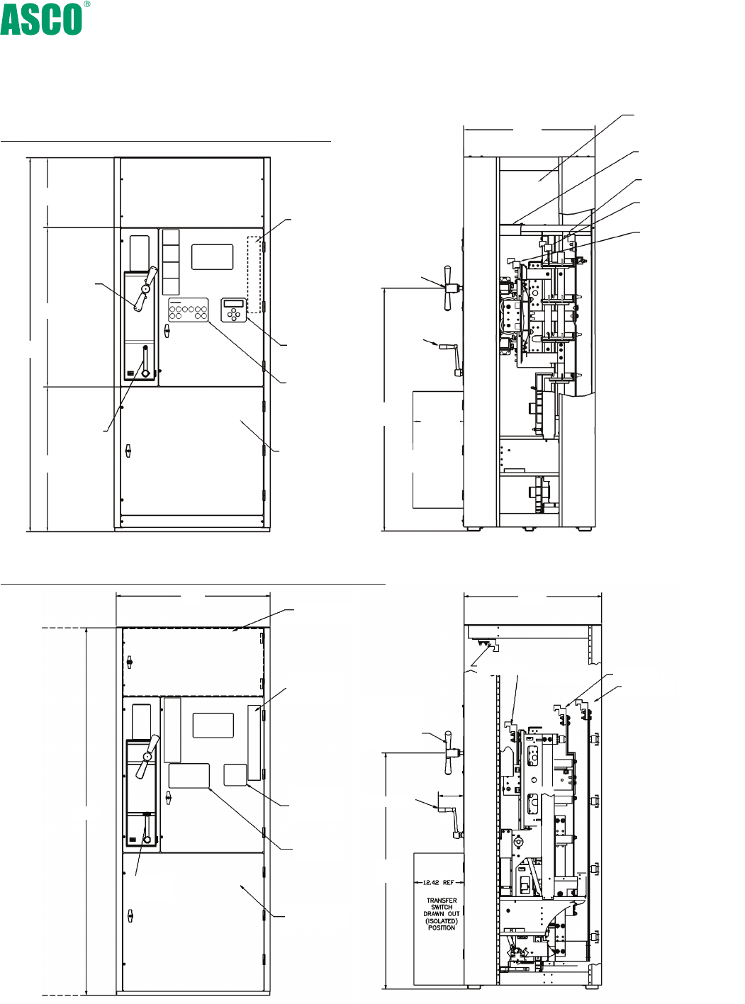
17.00
38.76
35.24
91.00
Transfer Switch
Compartment
Controls and
Indication
Group 5
Controller
User
Interface
Field Wiring
Terminal Block
(TB)
Bypass Handle
Isolation
Handle
59.05
REF
39.00
CG
12.42 REF
32.00
Cable
Compartment
Ground Bus
Load Lugs
Normal Lugs
Emergency Lugs
800 Amp Optional Front Connected Design
Bypass
Switch
Manual
Operation
Handle
Isolation
Handle
*All dimensions and weights
shown are approximate and
should not be used for con-
struction purposes. Certified
dimensions can be furnished
upon request.
27
Front Views (Covers Installed) Right Side Views (Covers Removed)
7000 series Designed to Fit Anywhere*
Optional Front Connected Design Saves Valuable Space
1000-1200 Amp Optional Front Connected Design
Field Wiring
Terminal Block
(TB)
Group 5
Controller
User
Interface
Controls and
Indication
Transfer Switch
Compartment
Bypass Switch
Manual Operation
Handle
Isolation Handle
Load Lugs
Normal Lugs
Emergency Lugs
Ground Bus
34.00
Cable Access
Hinge Cover
Isolation
Handle
91.00
38.00
59.05
REF
6.22
REF

www.EmersonNetworkPower.com/ASCO
Emerson Network Power - Global Headquarters
1050 Dearborn Drive
Columbus, OH 43085
Tel: +1 614 888 0246
ASCO Power Technologies - Global Headquarters
50 Hanover Road
Florham Park, NJ 07932
800-800-ASCO
www.ascoapu.com
Emerson. Consider it Solved., Emerson Network Power and the Emerson Network Power logo are trademarks and service marks of Emerson Electric Co. ©2014 Emerson Electric Co. All rights reserved.
Publication 3040 R14 © July 2014 Printed in the U.S.A.
