Emerson Fisher 1051 And 1052 Installation Instructions
2015-03-30
: Emerson Emerson-Fisher-1051-And-1052-Installation-Instructions-681952 emerson-fisher-1051-and-1052-installation-instructions-681952 emerson pdf
Open the PDF directly: View PDF ![]() .
.
Page Count: 40
www.Fisher.com
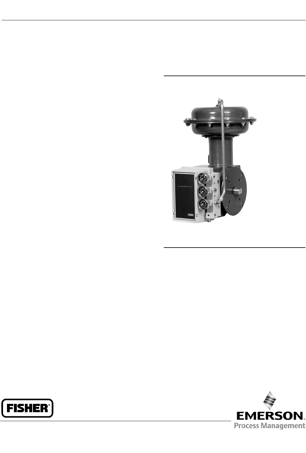
Fisherr1051 and 1052 Style H and J
Sizes 40, 60 and 70 Rotary Actuators
Contents
Introduction 1.................................
Scope of Manual 1.............................
Description 2.................................
Specifications 3...............................
Educational Services 3.........................
Principle of Operation 4........................
Installation 4..................................
Actuator Mounting 5..........................
Loading Connections 12........................
Adjustment 13.................................
1051 and 1052 Turnbuckle Adjustment 13........
1052 Spring Adjustment 14.....................
Initial Compression 14......................
Stroking Range 15.........................
Maintenance 15................................
Disassembly 16...............................
Assembly 18..................................
Changing Actuator Mounting 22..................
Changing Styles 22............................
Changing Positions 23.........................
Top-Mounted Handwheels and
Adjustable Travel Stops 25.......................
Handwheel and Travel Stop Operations 25........
Handwheel and Travel Stop Maintenance 26.......
For Top-Mounted Handwheels and Adjustable
Up Travel Stops 27..........................
For Adjustable Down Travel Stops 27.............
Figure 1. Fisher 1051 Actuator with H Mounting
Adaptation and 3610J Positioner
W4252
Parts Ordering 28...............................
Parts List 28...................................
Introduction
Scope of Manual
This manual provides installation, adjustment, operation, maintenance, and parts ordering information for Fisher
1051 (sizes 40 and 60) and 1052 (sizes 40, 60, and 70) diaphragm rotary actuators with H and J mounting adaptations
(see figures 1 and 2). Also, this instruction manual provides information for the optional top-mounted handwheel, and
both the optional up and down travel stops. Instructions for the control valve body, the positioner, accessories, and
other sizes or constructions of this actuator are covered in separate manuals.
Instruction Manual
D100320X012
1051 and 1052 H & J Actuators
October 2012

Instruction Manual
D100320X012
1051 and 1052 H & J Actuators
October 2012
2
Table 1. Fisher 1051 and 1052 Actuator Specifications
Operation
Direct Acting: Increasing loading pressure extends
the diaphragm rod out of the spring barrel
Service:
1051: For on-off or throttling service with positioner
1052: For on-off or throttling service with or without a
positioner
Actuator Sizes
1051: 40, and 60
1052: 40, 60, and 70
Maximum Diaphragm Sizing Pressure(2)(3)
Size 40: 4.5bar(65psig)
Size 60: 2.8bar(40psig)
Size 70: 3.8bar(55psig)
Maximum Diaphragm Casing Pressure(2)(3)
Size 40: 5.2bar(75psig)
Size 60:3.4bar(50psig)
Size 70: 4.5bar(65psig)
Maximum Valve Shaft Rotation
90, 75, or 60 deg with optional stops
Torque Limits (mm)(4)
Limited by maximum diaphragm sizing pressure or
tables 2 and 3, whichever is less
Stroking Time
Dependent on actuator size, rotation, spring rate,
initial spring compression, and supply pressure. If
stroking time is critical, consult your Emerson Process
Management sales office
Material Temperature Capabilities(3)
Nitrile Diaphragm or O-Rings(1):-40 to 82_C
(-40 to 180_F)
Silicone Diaphragm: -40 to 149_C(-40to300_F)
Travel Indication
Graduated disc and pointer combination located on
actuator end of valve shaft
Pressure Connections
1/4 NPT internal
Mounting Positions
Seefigure10
Approximate Weights
See table 8
Additional Specifications
For casing pressure ranges and for material
identification of the parts, see the Parts List
1. Nitrile O-rings are used in optional top-mounted handwheel, adjustable down travel stop, and adjustable up travel stop assemblies.
2. Use this value to determine the maximum torque output allowed.
3. The pressure / temperature limits in this manual and any applicable standard or code limitation for valve should not be exceeded.
4. Exceeding any torque requirements could damage the actuator and impair safe operation.
Do not install, operate, or maintain a 1051 or 1052 actuator without being fully trained and qualified in valve, actuator,
and accessory installation, operation, and maintenance. To avoid personal injury or property damage, it is important
to carefully read, understand, and follow all the contents of this manual, including all safety cautions and warnings. If
you have any questions about these instructions, contact your Emerson Process Management sales office before
proceeding.
Description
1051 and 1052 diaphragm rotary actuators are pneumatic spring-return actuators for use with rotary-control valves
and other equipment. The 1051 actuator can be used for on-off service, or it can be used for throttling service when
equipped with a valve positioner. The 1052 actuator can be used for on-off service, or it can be used for throttling
service when equipped with or without a valve positioner. The 1052 actuator spring is adjustable.
The H mounting adaptation permits the actuator to be used with equipment other than Fisher valve bodies. The
mounting brackets and couplings for rotary actuation are user-provided. This mounting adaptation includes a
flat-surface mounting plate that is drilled and tapped for attaching the user-provided bracket. Cap screws for attaching
the bracket are provided. H mounting also includes an output shaft (with milled flats) to provide the Double D rotary
output either directly or through a user-provided coupling. Output shaft diameters and torque limits are listed in table
2. Dimensional information for the mounting plate and output shaft are shown in figures 4, 5, and 6.
Instruction Manual
D100320X012
1051 and 1052 H & J Actuators
October 2012
3
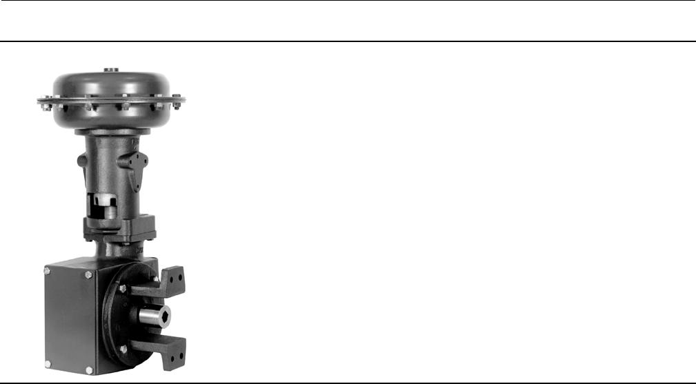
Figure 2. Fisher 1052 Actuator with J Mounting Adaptation
W4139-1
The J mounting adaptation permits the actuator to be used for rotary actuation of Fisher keyed-shaft butterfly valve
bodies and other keyed-shaft equipment. This mounting adaptation uses the standard butterfly valve mounting
bracket and provides an output shaft with an attached coupling for keyed equipment shafts. Coupling sizes and torque
limits are listed in table 3. Dimensional information for the mounting bracket and stub shaft coupling is shown in
figures4,5,and7.
Additionally, a top-mounted handwheel can be applied for infrequent service as a manual handwheel actuator. For
more frequent manual operation, a side-mounted handwheel actuator is available. Also, an adjustable up travel stop
can be added to limit the actuator stroke in the upward direction, or an adjustable down travel stop can be added to
limit actuator stroke in the downward direction.
Specifications
Specifications are shown in table 1 for 1051 and 1052 actuators. Specifications for a given 1051 or 1052 actuator as it
originally comes from the factory are stamped on a nameplate attached to the actuator.
Educational Services
For information on available courses for 1051 and 1052 Style H and J actuators, as well as a variety of other products,
contact:
Emerson Process Management
Educational Services, Registration
P.O. Box 190; 301 S. 1st Ave.
Marshalltown, IA 50158-2823
Phone: 800-338-8158 or
Phone: 641-754-3771
FAX: 641-754-3431
e-mail: education@emerson.com

Instruction Manual
D100320X012
1051 and 1052 H & J Actuators
October 2012
4
Table 2. Output Shaft Diameters and Torque Limits for Actuators With H Mounting
ACTUATOR SIZE OUTPUT SHAFT DIAMETER TORQUE LIMIT FOR H MOUNTING
mm Inches NDmInch-Pounds
40
22.2
28.6
38.1
7/8
1-1/8
1-1/2
240
468
1110
2120
4140
9815
60 28.6
38.1
1-1/8
1-1/2
468
1210
4140
10,680
70(1) 38.1 1-1/2 1210 10,680
1. 1052 actuator only.
Table 3. Acceptable Shaft Diameters and Torque Limits for Actuators With J Mounting
ACTUATOR SIZE COUPLING AVAILABILITY BY KEYED SHAFT DIAMETER TORQUE LIMIT FOR J MOUNTING
mm Inches NDmInch-Pounds
40
9.5
12.7
15.9
19.1
25.4
3/8
1/2
5/8
3/4
1
52
69
114
207
468
460
610
1010
1830
4140
60
19.1
25.4
31.8
38.1
50.8
3/4
1
1-1/4
1-1/2
2
207
468
1030
1360
2650
1830
4140
9110
12,000
23,430
70(1)
31.8
38.1
50.8
1-1/4
1-1/2
2(2)
1030
1360
2650
9110
12,000
23,430
1. 1052 actuator only.
2. Coupling supplied for mating with either 44.5 or 50.8 mm (1-3/4 or 2-inch) keyed shaft.
Principle of Operation
The diaphragm rod moves down as loading pressure is increased on top of the diaphragm. As the loading pressure is
decreased, the spring forces the diaphragm rod upward.
The spring and diaphragm have been selected to meet the requirements of the application and, in service, the
actuator should produce full travel of the valve or other operated equipment with the diaphragm pressure as indicated
on the nameplate.
Consult the separate positioner instruction manual for actuator principle of operation with positioner.
Installation
WARNING
Always wear protective gloves, clothing, and eyewear when performing any maintenance operations to avoid personal
injury.
To avoid personal injury or property damage caused by bursting of pressure retaining parts, be certain the service
conditions do not exceed the limits given in table 1. Use pressure limiting or pressure relieving devices to prevent the
diaphragm sizing pressure from exceeding the maximum allowable diaphragm sizing pressure.
Check with your process or safety engineer for any additional measures that must be taken to protect against process
media.
If installing into an existing application, also refer to the WARNING at the beginning of the Maintenance section in this
instruction manual.
Instruction Manual
D100320X012
1051 and 1052 H & J Actuators
October 2012
5
WARNING
To avoid personal injury or parts damage, do not use an operating pressure that exceeds the Maximum Diaphragm Casing
Pressure (table 1) or produces a torque greater than the Maximum Allowable Valve Shaft Torque (see Catalog 14). Use
pressure-limiting or pressure-relieving devices to prevent the diaphragm casing pressure from exceeding its limit.
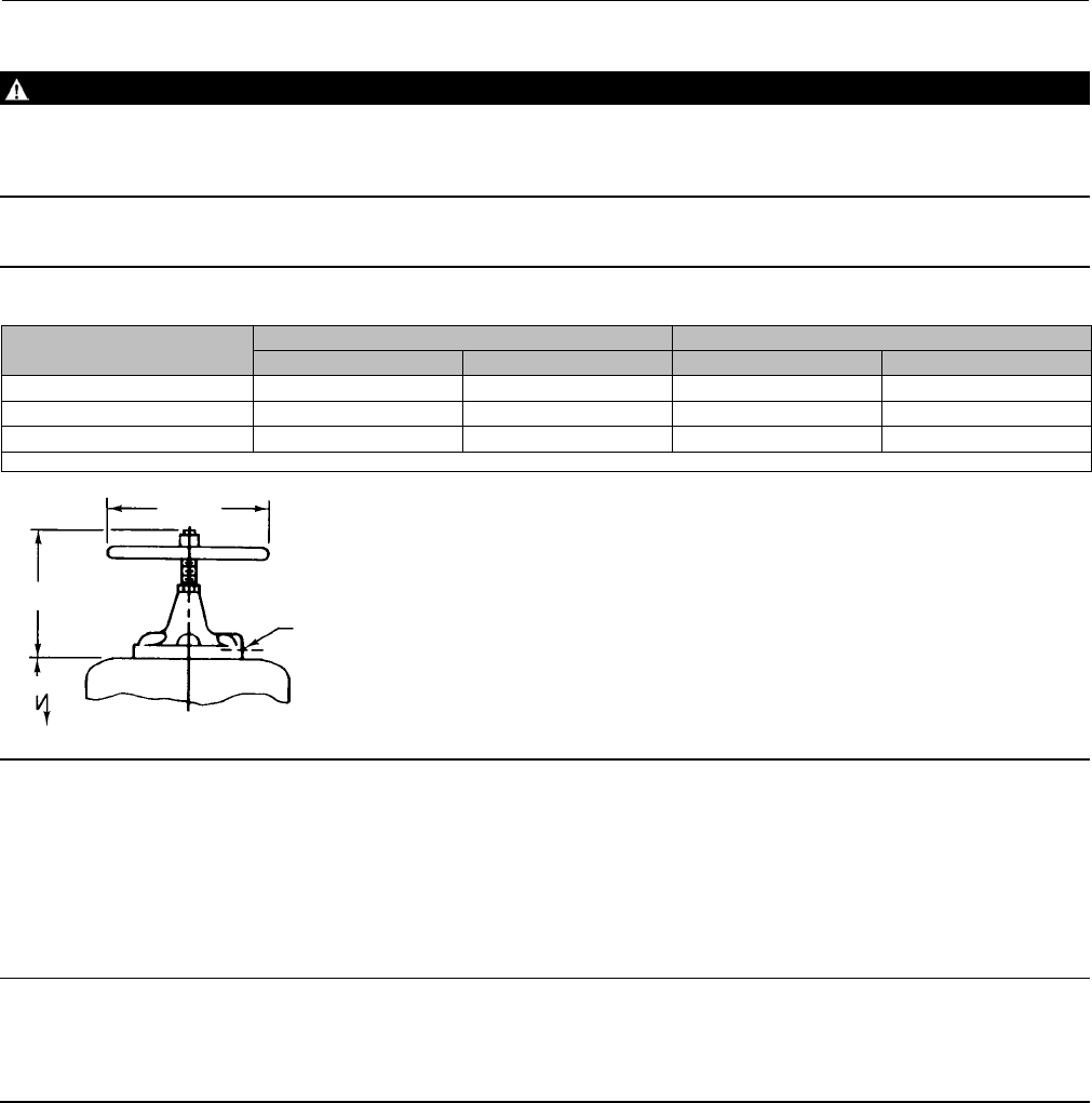
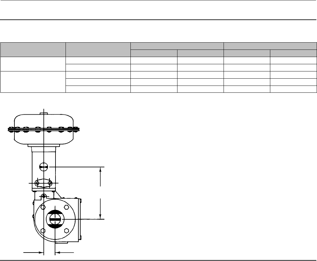
Figure 3. Top Mounted Handwheel
ACTUATOR SIZE HCJC
mm Inch mm Inch
40 281 11.06 356 14.00
60 359 14.12 432 17.00
70(1) 335 13.62 356 14.00
1. Size 70 available in 1052 only.
TOP-MOUNTED HANDWHEEL
19A1465-B
1/4 NPT
HC
JC(DIA)
E
Actuator Mounting
Usethefollowingstepstoconnecttheactuatortoavalvebody or other equipment. Unless otherwise specified, key
numbers are shown in figures 12 and 13. Mounting dimensions are shown in figures 4, 5, 6, and 7.
Note
For an actuator with an H mounting adaptation and a 22.2 through 38.1 mm (7/8 through 1-1/2 inch) output shaft, find
dimensions and center of gravity information in figures 3, 4, 5, 6, and 9, and approximate weights in table 8. This information is
required for proper fabrication of the user-provided bracket and coupling.
1. For an actuator with an Hmountingadaptation, attach an appropriate mounting bracket (not provided) to the
mounting plate (key 22) with the cap screws (key 78). See figures 4, 5, and 6 for mounting dimensions on the
mounting plate. Tighten the cap screws to the bolt torques listed in table 4.
2. Consult figure 10 for available mounting styles and positions. The actuator is normally positioned vertically with the
valve body or other equipment in a horizontal pipeline.

Instruction Manual
D100320X012
1051 and 1052 H & J Actuators
October 2012
6
Note
If the milled flats or the coupling on the end of the actuator output shaft (key 87) are oriented such that the output shaft cannot
accommodate the operated equipment shaft, refer to the Changing Positions portion of the Changing Actuator Mounting section.
This procedure describes how the output shaft can be repositioned to accommodate the operated equipment shaft.
3. If using an actuator with a Jmountingadaptation, note that the valve shaft coupling (key 90) is furnished with two
keyways lettered A and B as shown in figure 8 and 12 (letters C and D on the coupling are not used and can be
disregarded). Align the appropriate keyway with the keyway in the operated equipment shaft. If using a Fisher
butterfly valve, align the appropriate keyway on the coupling with the valve shaft keyway indicated in table 9. Then
install the woodruff key (key 91) in the shaft keyseat, and slide the coupling onto the shaft. It is helpful to apply a
light coat of grease to the inside of the coupling before sliding it onto the shaft.
4. For an actuator with an Hmountingadaptation, slide the actuator (with the user-provided mounting bracket
attached) into the user-provided coupling on the operated shaft. Then, secure the actuator to the operated
equipment in the desired mounting position with the appropriate fasteners, such as mounting cap screws. See
figures 4, 5 and 6 for output shaft dimensions.
5. For an actuator with a Jmountingadaptation, secure the mounting bracket (key 22) to the valve body with the cap
screws (key 78, not shown). Tighten the cap screws to the bolt torques in table 4. For 31.8 and 38.1 mm (1-1/4 and
1-1/2 inch) valve shafts, also place the two spacers (key 92, not shown) between the mounting bracket and valve
body during this step.
6. For an actuator with a Jmountingadaptation and a 50.8 mm (2-inch) output shaft (key 87, figure 14), note that the
valve shaft coupling (key 90, figure 14) is furnished with two keyways lettered A and B as shown in figure 8 (letters C
and D on the coupling are not used and can be disregarded). Align the appropriate keyway with the keyway in the
operated equipment shaft. Then, install the woodruff key (key 91, not shown in figure 14) in the shaft keyseat, and
slide the coupling onto the shaft using the appropriate coupling keyway (see table 9 and figure 8). It is helpful to
apply a light coat of grease to the inside of the coupling before sliding it onto the shaft. Secure the actuator
(user-provided mounting bracket) to the operated equipment in the desired mounting position with the
appropriate fasteners, such as mounting cap screws.
7. Follow the instructions given in the Turnbuckle Adjustment section before proceeding to the Loading Connection
portion of this section.
Table 4. Key 78 Cap Screw Torque Values
STYLE H MOUNTING
Actuator Size Valve Shaft Diameter Bolt Size Bolt Torque Key 78
Part Number
mm Inch Inch N•m lbf•ft
40 22.2 7/8 5/16 22.6 16.7 1C5958X0042
40 28.6 1-1/8 3/8 39 29 1A353124052
60 28.6 1-1/8 3/8 39 29 1A353124052
40 38.1 1-1/2 1/2 92 68 1A582324052
60, 70 38.1 1-1/2 1/2 92 68 1A582324052
STYLE J MOUNTING - FLAT PLATE MOUNTING
60, 70 44.5 1-3/4 1/2 92 68 1A582324052
60, 70 50.8 21/2 92 68 1A582324052
STYLE J MOUNTING - FISHER 7600, 9100, 9500 WITH KEYED SHAFT
40 9.5 3/8 3/8 39 29 1A341824052
40 12.7 1/2 3/8 39 29 1A341824052
40 15.9 5/8 3/8 39 29 1A341824052
40 19.1 3/4 3/8 39 29 1A341824052
60 19.1 3/4 3/8 39 29 1A341824052
40 25.4 13/8 39 29 1A341824052
60 25.4 13/8 39 29 1A341824052
60, 70 31.8 1-1/4 5/8 163 120 1P1477X0012
60, 70 38.1 1-1/2 5/8 163 120 1P1477X0012
Instruction Manual
D100320X012
1051 and 1052 H & J Actuators
October 2012
7
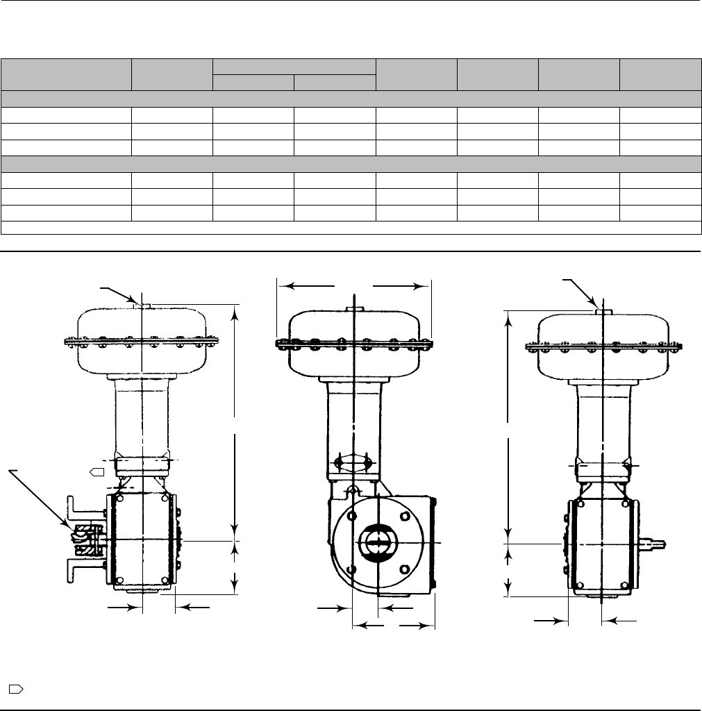
Table 5. Style H or J Mounting Dimensions
ACTUATOR SIZE CEF H P Y
1051 1052
mm
40 333 505 607 54 114 175 73
60 473 749 876 64 121 186 76
70(1) 536 --- 849 64 121 186 76
Inch
40 13.12 19.88 23.88 2.12 4.50 6.88 2.88
60 18.62 29.50 34.50 2.50 4.75 7.31 3.00
70(1) 21.12 --- 33.44 2.50 4.75 7.31 3.00
1. Size 70 available in 1052 only.
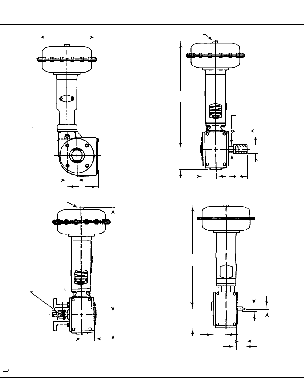
Figure 4. Fisher 1051 Mounting Dimensions (refer to table 5)
1/4 NPT
19A1465-C
C0577-3
NOTE:
SEE PARTS LIST FOR WOODRUFF KEY NUMBERS
1
1
1/4 NPT C(DIA)
EE
H
YF
P
H
Y
1051 1051 STYLE H
MOUNTING ADAPTATION
WOODRUFF
KEY
1051 STYLE J
MOUNTING ADAPTATION
19A1459-B
19A1459-B
Instruction Manual
D100320X012
1051 and 1052 H & J Actuators
October 2012
8
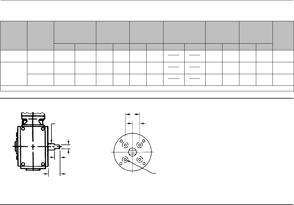
Figure 5. Fisher 1052 Mounting Dimensions (refer to table 5)
C0676-3
NOTE:
SEE PARTS LIST FOR WOODRUFF KEY NUMBERS
1
19A1467-E /
1
1/4 NPT
C(DIA)
E
H
Y
F
P
1052
WOODRUFF
KEY
1052 STYLE J ADAPTATION
9.5 THRU 38.1 mm (3/8 THRU 1-1/2-INCH) OUTPUT SHAFTS
19A1461-D
19A1461-G
1/4 NPT
E
H
Y
1052 STYLE J MOUNTING ADAPTATION
FOR 44.5 AND 50.8 mm (1-3/4 AND 2-INCH)
KEYED EQUIPMENT SHAFT
19A1461-D
1052 STYLE H ADAPTATION
12.7 THRU 38.1 mm (1/2 THRU 1-1/2-INCH) OUTPUT SHAFTS
E
H
Y
S(DIA)
M
K
N
S
L
V
K
Instruction Manual
D100320X012
1051 and 1052 H & J Actuators
October 2012
9
Table 6. Style H Mounting Dimensions
ACTUATOR
SIZE 1051
ACTUATOR
SIZE 1052
S
ACTUATOR
OUTPUT SHAFT
DIAMETER
V L K(1) T U W
mm Inch mm Inch mm Inch mm Inch mm Inch mm Inch
40 40 22.2 7/8 26.2 1.03 19.1 0.75 15.75
15.62
0.620
0.615 57.2 2.25 28.4 1.12 5/16-18
UNC
40 & 60
40 & 60 28.6 1-1/8 26.2 1.03 19.1 0.75 22.10
21.97
0.870
0.865 76.2 3.00 38.1 1.50 3/8-16
UNC
40, 60 & 70 38.1 1-1/2 28.4 1.50 28.4 1.12 28.45
28.32
1.120
1.115 88.9 3.50 44.5 1.75 1/2-13
UNC
1. Tolerance for the K dimension is indicated by showing maximum and minimum dimensions.
Figure 6. Fisher 1051 and 1052 Style H Mounting Dimensions (refer to table 6)
22.2 THRU 38.1 mm
(7/8 THRU 1-1/2 INCH)
OUTPUT SHAFTS WITH
STYLE H MOUNTING
22.2 THRU 38.1 mm
(7/8 THRU 1-1/2 INCH)
OUTPUT SHAFTS WITH
STYLE H MOUNTING
S(DIA)
K
L
V
T
U
W(DIA)
19A1461-D
A4997 19A1459-B
A3254-1
Instruction Manual
D100320X012
1051 and 1052 H & J Actuators
October 2012
10
Table 7. Style J Mounting Dimensions
ACTUATOR
SIZE 1051
& 1052
VALVE SHAFT
DIAMETER
COUPLING(1)
INNER
DIAMETER
V L(2) K T U W
mm Inch mm Inch mm Inch mm Inch mm Inch mm Inch mm Inch mm Inch
40
9.5 3/8 9.53
9.58
0.375
0.377 137 5.38 39.6 1.56 15.7 0.62 117 4.62 --- --- 11.2 0.44
12.7 1/2 12.70
12.75
0.500
0.502 137 5.38 39.6 1.56 15.7 0.62 117 4.62 --- --- 11.2 0.44
15.9 5/8 15.90
15.95
0.626
0.628 160 6.31 49.3 1.94 25.4 1.00 146 5.75 31.8 1.25 11.2 0.44
40 & 60
19.1 3/4 19.05
19.10
0.750
0.752 160 6.31 47.8 1.88 20.6 0.81 146 5.75 31.8 1.25 11.2 0.44
25.4 125.43
25.48
1.0010
1.0025 160 6.31 47.8 1.88 17.5 0.69 146 5.75 31.8 1.25 11.2 0.44
60 & 70(3)
31.8 1-1/4 31.75
31.80
1.250
1.252 148 5.81 68.3 2.69 30.2 1.19 210 8.25 50.8 2.00 17.5 0.69
38.1 1-1/2 38.13
38.18
1.501
1.503 148 5.81 68.3 2.69 23.9 0.94 210 8.25 50.8 2.00 17.5 0.69
60 & 70(3)
44.5
&50.8
1-3/4
&2
44.45
44.50
1.750
1.752 123 4.84 69.9 2.75 --- --- 88.9 3.50 44.5 1.75 1/2-13
UNC(4)
1/2-13
UNC(5)
50.8 250.83
50.90
2.001
2.004 123 4.84 69.9 2.75 --- --- 88.9 3.50 44.5 1.75 1/2-13
UNC(4)
1/2-13
UNC(5)
1. Tolerance for the Coupling Inner diameter is indicated by showing maximum and minimum dimensions.
2. The L dimension is the matchline to the end of the actuator shaft.
3. Size 70 is only available for the 1052.
4. 25.4 mm deep.
5.1inchdeep.
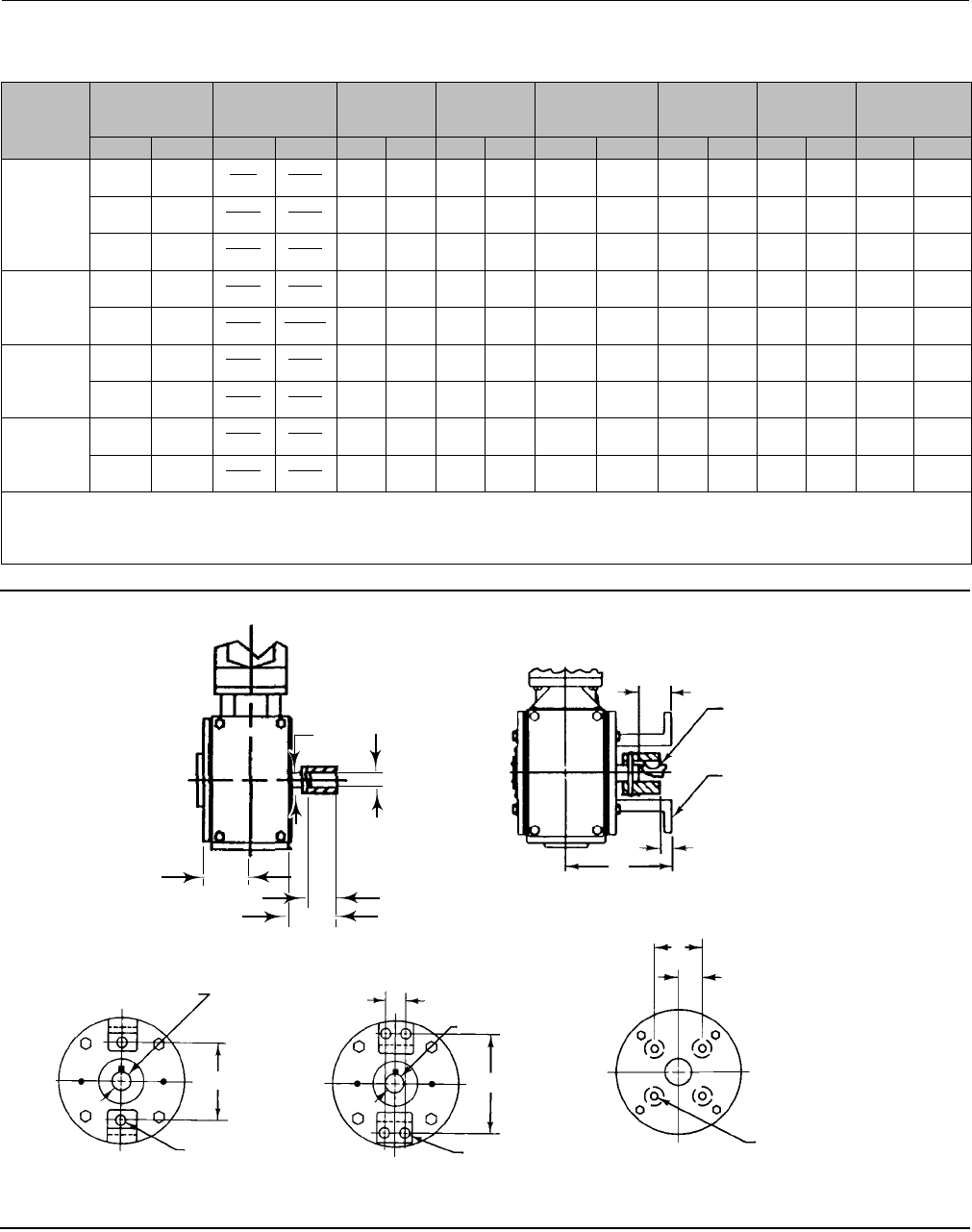
Figure 7. Fisher 1051 and 1052 Style J Mounting Dimensions (refer to table 7)
Y
S
L
V
19A1461-G
STYLE J MOUNTING
44.5 and 50.8 mm (1-3/4 and 2-INCH)
44.5 AND 50.8 mm (1-3/4 AND 2-INCH)
KEYED EQUIPMENT SHAFTS WITH
STYLE J MOUNTING
STYLE J MOUNTING
9.5 through 38.1 mm
(3/8 through 1-1/2 INCH)
19A1465-B
A4996 V
K
L
WOODRUFF
KEY
MOUNTING YOKE
(KEY 22)
15.9 THROUGH 38.1 mm
(5/8 THROUGH 1-1/2 INCH)
VALVE SHAFTS WITH STYLE J MOUNTING
9.5 AND 12.7 mm
(3/8 AND 1/2 INCH) VALVE SHAFTS
WITH STYLE J MOUNTING
COUPLING INNER
DIAMETER COUPLING INNER
DIAMETER
U
U
T
T
T
W
W(DIA)W(DIA)
19A1465-B 19A1465-B
19A1459-B
A3254-1
A3254-1
COUPLING INNER
DIAMETER
Instruction Manual
D100320X012
1051 and 1052 H & J Actuators
October 2012
11
Table 8. Approximate Actuator Weights
SIZE 1051 1052 TOP-MOUNTED HANDWHEEL
Kg Lb Kg Lb Kg Lb
40
60
70
43
89
---
94
197
---
45
92
123
99
203
272
7.3
11
21.3
16
24
47
Table 9. Keyway Alignment Information(1)
DESIRED
ACTUATOR
ACTION
DESIRED SHAFT
ROTATION,
DEGREES
ACTUATOR
MOUNTING
POSITION
COUPLING
KEYWAY TO
USE(3)
VALVE SHAFT KEYWAY TO USE FOR FISHTAIL™ DISC VALVE BODIES(2)
(SEE FIGURE 10)
Clockwise to
Close Valve Action(4)
Counterclockwise to
Close Valve Action(4)
Flow Left to
Right(4)
Flow Right to
Left(4)
Flow Left to
Right(4)
Flow Right to
Left(4)
Push Down to
Open (PDTO) 60 or 90
1 B Nose Tail Tail Nose
2 A Tail Nose Nose Tail
3 B Tail Nose Nose Tail
4 A Nose Tail Tail Nose
Push Down to
Close (PDTC) 60(5) or 90
1 A Tail Nose Tail Nose
2 B Tail Nose Tail Nose
3 A Nose Tail Nose Tail
4 B Nose Tail Nose Tail
1. For actuators with J mounting.
2. For conventional disc valve bodies, use either valve shaft keyway.
3.Seefigure10forreferencecouplingorientationtousewiththistable.
4. When viewed from actuator side of valve body.
5. For 60-degree rotation with PDTC action, the coupling and actuator output shaft assembly will be offset 30 degrees clockwise (for actuator housing construction style B) or counterclockwise
(for actuator housing construction Style A) in the lever when viewed from the splined end of the actuator shaft. 30 degrees is one spline tooth for 9.5, 12.7, and 15.9 mm (3/8, 1/2, and
5/8-inch) valve shafts and two spline teeth for 19.1 through 38.1 mm (3/4 through 1-1/2 inch) valve shafts.
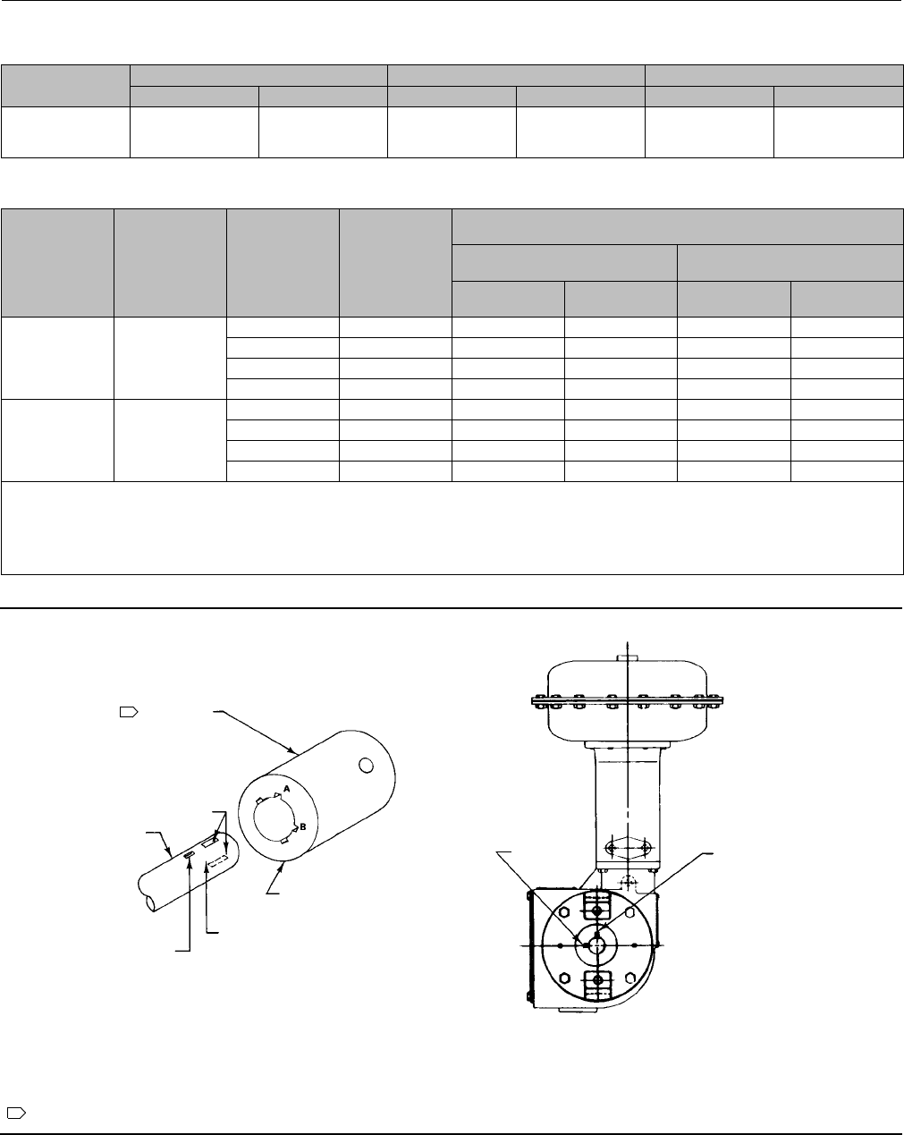
Figure 8. Valve Shaft Coupling
EXPLODED VIEW OF VALVE SHAFT
AND COUPLING
REFERENCE COUPLING ORIENTATION
FOR TABLE 9
NOTE:
FOR USE WITH J MOUNTING ADAPTATION (UP TO 50.8 mm (2-INCH) KEYED SHAFT DIAMETERS.
1
1
A3253-1
FULL KEYWAY
LOCATED ON
NOSE AND TAIL
SIDE OF VALVE SHAFT
VALVE SHAFT
COUPLING
PARTIAL KEYWAY
FOR DETERMINING
DISC POSITION
USE APPROPRIATE LETTERED
KEYWAY AS INDICATED IN
TABLE 9
USE APPROPRIATE
VALVE SHAFT
KEYWAY AS
INDICATED
IN TABLE 9
KEYWAY A KEYWAY B
ABOVE
KEYWAY A
19B1465-B
Instruction Manual
D100320X012
1051 and 1052 H & J Actuators
October 2012
12
Figure 9. Center of Gravity Dimensions
ACTUATOR TYPE ACTUATOR SIZE X Y
mm Inch mm Inch
1051 40 15 0.6 191 7.5
60 10 0.4 361 14.2
1052
40 15 0.6 241 9.5
60 10 0.4 432 17.0
70 23 0.9 488 19.2
Y
X
19A1459-B
A3255
Loading Connection
1. Connect the loading pressure piping to the pressure connection in the top of the diaphragm casing.
For size 40 through 60 actuators, run either NPS 1/4 pipe or 3/8-inch tubing between the NPT 1/4 pressure connection
and the positioner or automatic controller.
For size 70 actuators, run either pipe or tubing between the pressure connection and the positioner or automatic
controller. If necessary, remove the 1/4-inch bushing in the pressure connection to increase connection size.
2. Keepthelengthofpipeortubingasshortaspossibletoavoid transmission lag in the control signal. If an accessory
(such as a volume booster or a positioner) is used, be sure that the accessory is properly connected to the actuator.
If a positioner is part of the assembly, the pressure connection to the actuator will normally be made at the factory.
3. When the actuator is completely installed and connected to the instrument, check for correct action (air-to-open or
air-to-close) to match the controlling instrument. For successful operation, the actuator stem and operating shaft
mustmovefreelyinresponsetotheloadingpressurechangeonthediaphragm.

Instruction Manual
D100320X012
1051 and 1052 H & J Actuators
October 2012
13
Adjustment
WARNING
Before performing any adjustment steps, follow the steps in the WARNING at the beginning of the Maintenance section.
1051 and 1052 Turnbuckle Adjustment
Correct turnbuckle adjustment ensures that the valve body or other operated equipment is correctly closed when the
actuator is against its travel stops. The turnbuckle adjustment is the only adjustment necessary on the 1051 actuator.
Key numbers used in this procedure are shown in figure 12 for 1051 actuators and in figure 13 for 1052 actuators.
For accurate adjustment, remove the valve body or other operated equipment from the pipeline.
A regulated air supply will be required to stroke the actuator. Consult table 10 for the sizes of the three open end
wrenches required for this procedure.
1. Remove the access plate (key 59). Also remove the machine screws (key 60), if present.
Note
For the most accurate adjustment of the actuator, do not remove the cover (key 33) during this procedure.
2. Loosen the lower locknut (key 16).
Table 10. Wrench Sizes Required for Turnbuckle Adjustment, Inches
Actuator Size Turnbuckle (Key 57) Lower Locknut (Key 16) Upper Locknut (Key 58)
1051 & 1052 40
60
1-1/8
1-5/16
3/4
15/16
1-1/8
1-5/16
1052 70 1-5/16 1-1/8 1-5/16
3. Make sure the actuator housing (key 20) is clear of any tools or other instruments that could obstruct the actuator
stroke path. Pressure the diaphragm casing enough to stroke the actuator down so that the left-hand threaded
upper locknut (key 58) is accessible through the access opening. Loosen the locknut.
4. Useoneofthefollowing:
a. For push-down-to-close action–Slowly stroke the actuator to the down travel stop. Consult the appropriate
instruction manual for determining the closed position of the valve body or other operated equipment. Adjust
the turnbuckle (key 57) until the closed position is reached. Lock this adjustment with the left-hand threaded
locknut (key 58). Stroke the actuator to the mid-travel position, and tighten the locknut (key 16). Tighten each
locknut to the appropriate torque value listed in table 11.
WARNING
Exceeding any torque requirements could damage the actuator and impair safe operation.

Instruction Manual
D100320X012
1051 and 1052 H & J Actuators
October 2012
14
b. For push-down-to-open action–Consult the appropriate instruction manual for determining the closed position
of the valve or other operated equipment. Release all pressure from the diaphragm casing, making sure the
diaphragm is against its up travel stop. Be sure that the optional handwheel is adjusted to its topmost position so
that the closed position of the actuator and valve body or other operated equipment can be reached
simultaneously. Check the position of the valve body or other operated equipment withrespecttoitsproperly
closed position. Stroke the actuator so the turnbuckle (key 57) is accessible through the access opening. Adjust
the linkage. Release pressure to the actuator, and check the new adjustment. Continue this procedure until the
operated equipment is in the closed position when the actuator is resting on its up travel stop. Tighten locknut
(key 16). Stroke the actuator, and tighten the left-hand threaded locknut (key 58). Tighten each locknut to the
appropriatetorquevaluelistedintable11.
WARNING
Exceeding any torque requirements could damage the actuator and impair safe operation.
5. Replace the access plate (key 59). Also, replace the machine screws (key 60), if present.
6. Loosen the self-tapping screws (key 38), and adjust the travel indicator (key 37). Retighten the self-tapping screws.
1052 Spring Adjustment
Initial Compression
The 1052 nameplate specifies a spring set, which is the initial compression adjusted into the actuator spring, Initial
compression is the casing pressure at which the diaphragm and diaphragm rod begin to move away from the up travel
stop with the actuator disconnected from the valve body or other operated equipment. (With the actuator connected
and pressure applied to the valve body or other operated equipment, a higher casing pressure will be required to start
actuator travel). The initial compression was selected (based upon the service conditions specified when the actuator
was ordered) so that when the actuator and valve body or other operated equipment are in service, the operated
equipment will close properly and full travel will be obtained within a diaphragm casing pressure range of 0 to 1.2, 0 to
2.3,0to2.8or0to3.8bar(0to18,0to33,0to40,or0to55psig)dependingonspecificactuatorsizeand
construction.
If the actuator has been disassembled or if the spring adjustment was changed, and it is desired to match the initial
compression stated on the nameplate, make sure the rod end bearing (key 17, figure 13) has been disconnected from
the lever (key 27, figure 13). Adjust the spring so that the diaphragm rod just starts to travel at the spring set pressure
specified on the nameplate. Be sure the rod end bearing does not hit the lever as the diaphragm and diaphragm rod
move away from the up travel stop.
To adjust the spring, insert a round rod into one of the slots in the lower bearing seat (key 73, figure 13). Slot diameter
is 9.5 mm (3/8-inch) for size 40 actuators, 15.9 mm (5/8-inch) for size 60 actuators, and 19.1 mm (3/4-inch) for size 70
actuators.
Rotate the bearing seat to move it toward the casings (keys 1 and 2, figure 13) to increase initial compression or away
from the casings to decrease initial compression.

Instruction Manual
D100320X012
1051 and 1052 H & J Actuators
October 2012
15
Table 11. Recommended Bolting Torques(1)
KEY NUMBER
ACTUATOR SIZE
40 60 70
NDmlbfDft NDmlbfDft NDmlbfDft
627 20 27 20 27 20
7&8 41 30 41 30 102 75
934 25 102 75 102 75
16 34 25 61 45 102 75
18 81 60 163 120 271 200
21 23 17 68 50 68 50
23 34 25 81 60 81 60
28 81 60 163 120 271 200
34 34 25 81 60 81 60
40 9 7 9 7 9 7
54 handwheel 34 25 34 25 34 25
54 down stop 27 20 66 49 69 51
58 102 75 163 120 163 120
141 41 30 41 30 81 60
1. Exceeding any torque requirements could damage the actuator and impair safe operation.
Stroking Range
The initial spring set listed on the nameplate has been determined to be the optimum setting, and it is not
recommended to make spring adjustments that will cause this value to change or be exceeded. For
push-down-to-open (PDTO) action, the initial spring set is normally the maximum allowable to provide the maximum
spring closing force. Any increase of this setting could over-stress the spring at full travel. For push-down-to-close
(PDTC) action, the initial spring set has been determined to be the optimum balance between the air to close and the
spring to open breakout torque.
If the 1052 actuator is to be changed from one action to another (i.e., from PDTC to PDTO), first refer to the initial
spring compression values listed in the table for keys 11 and 13 in the Parts List section. Then adjust the unit according
to the procedures in the Initial Compression portion ofthissection.
Maintenance
Actuator parts are subject to normal wear and must be inspected and replaced as necessary. The frequency of
inspection and replacement depends upon the severity of service conditions. Instructions are given below for
disassembly and assembly of parts. Key numbers referenced in the following steps are shown in figure 12 for 1051
actuators and in figure 13 for 1052 actuators unless otherwise specified.
WARNING
Avoid personal injury or property damage from sudden release of process pressure or uncontrolled movement of parts.
Before performing any maintenance operations:
DDo not remove the actuator from the valve while the valve is still pressurized.
DAlways wear protective gloves, clothing, and eyewear when performing any maintenance operations to avoid personal
injury.
DDisconnect any operating lines providing air pressure, electric power, or a control signal to the actuator. Be sure the
actuator cannot suddenly open or close the valve.

Instruction Manual
D100320X012
1051 and 1052 H & J Actuators
October 2012
16
DUse bypass valves or completely shut off the process to isolate the valve from process pressure. Relieve process pressure
from both sides of the valve. Drain the process media from both sides of the valve.
DVent the power actuator loading pressure and relieve any actuator spring precompression.
DUse lock-out procedures to be sure that the above measures stay in effect while you work on the equipment.
DThe valve packing box may contain process fluids that are pressurized, even when the valve has been removed from the
pipeline. Process fluids may spray out under pressure when removing the packing hardware or packing rings, or when
loosening the packing box pipe plug.
DCheck with your process or safety engineer for any additional measures that must be taken to protect against process
media.
Disassembly
The following procedure describes how the actuator can be completely disassembled. When inspection or repairs are
required, perform only those steps necessary to accomplish the procedure. Do not under ordinary circumstances
removethecapscrews(keys7,8,and21).
CAUTION
Cap screw (key 18) must be disengaged from the lever (key 27) before removing the diaphragm casing (key 1). Failure to do
so will allow the spring precompression to rotate the valve body or other operated equipment beyond its fully open or
closed position. This could cause damage to the operated equipment.
1. Bypass the valve or other operated equipment. Relieve all actuator loading pressure, and remove the tubing or pipe
from the top of the actuator.
2. Remove the positioner, if one is used.
3. Mark the orientation of the travel indicator (key 37) with respect to the travel indicator scale (key 35). Then,
unscrew the cap screws and washers (keys 34 and 63), and remove the cover (key 33).
4. Remove the retaining ring (key 30), and then remove the hub (key 29) from the cover.
5. Check the condition of the bearing (key 31). If replacement of the bearing is necessary, the travel indicator scale
(key 35) must first be removed by removing the self-tapping screws (key 36). Mark the orientation of the travel
indicator scale on the cover before removing it.
CAUTION
When removing the actuator from the valve body, do not use a hammer or similar tool to drive the lever (key 27) or
actuator off the output shaft (key 87). Driving the lever or actuator could damage operated equipment. For valves, driving
the lever (key 27) could move the valve disc and bearings away from the centered position causing subsequent damage to
valve parts.
If necessary, use a wheel puller to remove the lever. It is permissible to tap the wheel puller screw lightly to loosen the
lever, but hitting the screw with excessive force could also damage operated parts or disrupt the centered position of a
valve disc or other equipment.
6. For an actuator with an H mounting adaptation and a 22.2 through 38.1 mm (7/8 through 1-1/2 inch) output shaft,
unscrew the cap screws (key 78) and remove the actuator from the operated equipment. Mark the orientation of
the lever (key 27) with respect to the output shaft (key 87).Thismarkingisusedduringreassemblytoallowfor
proper lever/output shaft positioning.

Instruction Manual
D100320X012
1051 and 1052 H & J Actuators
October 2012
17
Then, loosen the cap screw (key 28) so that the output shaft is free to slide off the lever. With the lever and output
shaft properly marked, unscrew the cap screws (key 23) and remove the mounting plate (key 22) and output shaft (key
87) assembly from the actuator housing (key 20). If necessary, remove the retaining ring (key 88) and separate the
output shaft from the mounting plate.
7. For an actuator with a J mounting adaptation (see figures 12 and 13) with a 50.8 mm (2-inch) output shaft (see
figure 14) and proceed as follows:
a. Remove the cap screws (key 78, not shown in figures 12 and 13) and remove the actuator from the operated
equipment. For an actuator with J mounting and a 31.8 or 38.1 mm (1-1/4 or 1-1/2 inch) valve shaft diameter,
two spacers (key 92, not shown in figures 12 and 13) are also removed with the cap screws (key 78).
b. When separating the output shaft (key 87) and coupling (key 90) from the operated shaft, remember to remove
the woodruff key (key 91, not shown in figure 14) from the operated shaft keyway.
c. Mark the orientation of the lever (key 27, figures 12 and 13) with respect to the output shaft (key 87). This
marking is used during reassembly to allow for proper lever/output shaft positioning,
d. Loosen the cap screw (key 28, figures 12 and 13) so that the output shaft is free to slide off the lever.
e. With the lever and output shaft properly marked, unscrew the cap screws (key 23) and remove either the
mounting bracket (key 22, figures 12 and 13 for J mounting) or the mounting plate (key 22, figure 14 for H
mounting) plus the attached output shaft (key 87) from the actuator housing (key 20).
f. If necessary, remove the retaining ring (key 88) and slide the mounting bracket or mounting plate off the output
shaft.
8. Check the bearing (key 67) in the mounting bracket or mounting plate (key 22). Press out and replace the bearing if
necessary.
9. Heat the hex nut (key 19) to 177_C(350_F) long enough for the thread-locking adhesive (high strength) (key 77) to
lose its holding strength. Then, remove the cap screw and hex nut (keys 18 and 19), and remove the lever (key 27)
from the housing.
10. Rotate the handwheel (if one is used) counter-clockwise until the handwheel is not compressing the spring
(key 11).
WARNING
To avoid personal injury from precompressed spring force suddenly thrusting the upper diaphragm casing (key 1) away
from the actuator, relieve 1052 spring compression, or carefully remove 1051 casing cap screws by following the
instructions presented in the next two steps before proceeding further.
11. To relieve 1052 spring compression, insert a round rod into one of the slots in the lower bearing seat (key 73). Slot
diameteris9.5mm(3/8inch)forsize40actuators,15.9mm(5/8inch)forsize60actuators,and19.1mm(3/4
inch) for size 70 actuators. Use the rod to rotate the lower bearing seat, and move it away from the actuator
casings. Continue rotating the lower bearing seat until spring compression is completely removed.
12. Loosen, but do not remove, all casing cap screws (key 5). Make sure there is no spring force on the 1051 upper
diaphragm casing. Unscrew and remove the cap screws and hex nuts (keys 5 and 6), and then remove the upper
diaphragm casing and the diaphragm (key 3).
13. Proceed as appropriate:
For 1051 actuators,
a. Read and follow the warning printed on the nameplate (key 56) located on the diaphragm plate (key 4).

Instruction Manual
D100320X012
1051 and 1052 H & J Actuators
October 2012
18
b. Pull the diaphragm plate (key 4) and attached parts out of the actuator. The spring (key 11), diaphragm rod (key
10), cap screw (key 9), spring seat (key 13), hex nut (key 58), turnbuckle (key 57), hex nut (key 16), and rod end
bearing (key 17) will be attached to the diaphragm head.
WARNING
For 1051 actuators, the diaphragm plate (key 4) may be wedged against the diaphragm rod (key 10), thereby preventing
thespringcompressionfrombeingrelievedasthecapscrew(key 9) is loosened. Dislodge the diaphragm head from the
diaphragm rod by loosening the cap screw (key 9) one full turn and tapping the underside of the diaphragm head until it
follows the cap screw disassembly. Failure to check for this situation before removing the cap screw (key 9) could cause
personal injury due to the sudden release of spring compression as the cap screw is disengaged.
c. Slowly remove the cap screw (key 9) while making sure that the diaphragm head is following the cap screw
removal. Note that spring load will be zero before the cap screw is completely removed. Then separate the
remaining parts of the assembly.
For 1052 actuators,
a. Remove the rod end bearing (key 17), the hex nut (key 16), the turnbuckle (key 57), and the hex nut (key 58)
from the diaphragm rod (key 10).
b. Pull the diaphragm plate (key 4) and attached parts out of the actuator. Then remove the cap screw (key 9) to
separate the diaphragm plate and the diaphragm rod.
c. Proceed as appropriate:
DFor actuator designs without a set screw in the spring barrel (key 12), remove the actuator spring (key 11) from the
actuator. If it is necessary to remove the adjustor (key 74) from the spring barrel during this procedure, heat the
base of the adjustor to 177_C(350_F) long enough for the thread locking adhesive (high strength) (key 77) to lose
its holding strength. Then, unscrew the adjustor from the spring barrel. If the spring seat and the lower bearing seat
(key 13 and 73) are to be replaced, unscrew the lower bearing seat from the adjustor, and then remove the thrust
bearing and the bearing races (keys 71 and 72) from the lower bearing seat.
DFor actuator designs with a set screw, (key 75), remove the actuator spring (key 11) from the actuator. If the spring
seat and the lower bearing seat (keys 13 and 73) are to be replaced, unscrew the lower bearing seat from the
adjustor, and then remove the thrust bearing and the bearing races (keys 71 and 72) from the lower bearing seat. If
it is necessary to remove the spring adjustment parts, heat the set screw (key 75) to 177_C(350_F) long enough for
the thread-locking adhesive (high strength) (key 77) to lose its holding strength, and then loosen the set screw (key
75). Unscrew the spring adjustor (key 74) from the spring barrel (key 12).
Assembly
This procedure assumes that the actuator is completely disassembled. If the actuator is not completely disassembled,
start these instructions at the appropriate step. Key numbers used are shown in figure 12 for 1051 actuators and in
figure 13 for 1052 actuators.
1. If the 1052 spring barrel (key 12) was removed from the housing (key 10), align the spring barrel to the housing as
described below to ensure that the offset hole in the base of the spring barrel is located properly.
For size 40 and 60 actuators, note that one of the accessory mounting bosses on the spring barrel is closer to the
diaphragm end of the spring barrel. Place the spring barrel on the housing with the upper boss (the one closer to the
diaphragm end) on the same side as the boss located on the housing (see figure 13). This ensures proper positioning of
the offset hole. Secure the spring barrel with the cap screws (key 21).

Instruction Manual
D100320X012
1051 and 1052 H & J Actuators
October 2012
19
For size 70 actuators, the spring barrel need not be aligned in any particular position when placing it on the housing.
Note
Refer to table 11 for bolting torques for actuator bolts and cap screws. Exceeding any torque requirement may impair the safe
operation of the actuator.
2. Proceed as appropriate:
For 1051 actuators,
a. Coat the thread of the cap screw (key 9) and the tapered end of the diaphragm rod (key 10) with lithium grease
(key 76).
b. Assemble the diaphragm rod, spring seat (key 13), spring (key 11), and diaphragm plate (key 4), and secure with
the cap screw (key 9). Tightening the cap screw will compress the spring. Be certain the tapered end of the
diaphragm rod is seated in the corresponding hole in the diaphragm plate, that the spring is seated in the spring
seat, and that the cap screw is tightened to the torque specified in table 11.
c. Install the hex nut (key 58), turnbuckle (key 57), hex nut (key 16), and rod end bearing (key 17) onto the
diaphragm rod.
d. Be certain the travel stops (key 8) are located as shown in figure 11.
e. Install the diaphragm plate and attached parts into the actuator.
f. Be sure the warning nameplate (key 56) is in place. Install the diaphragm (key 3) and the upper diaphragm casing
(key 1). Install the cap screws and hex nuts (keys 5 and 6). Tighten the cap screws evenly in a crisscross pattern to
compress the spring and secure the upper diaphragm casing. Tighten these cap screws to the torques shown in
table 11.
For 1052 actuators,
a. Proceed as appropriate:
DFor actuator designs without a set screw in the spring barrel (key 12), if the adjustor and attached parts were
removed, first clean and then lubricate the upper threads of the adjustor (key 74) with lithium grease (key 76) as
shown in figure 13. Install the lower bearing seat (key 73), the thrust bearing (key 71), the thrust bearing races (key
72), and the spring seat (key 13) onto the adjustor. Then, first clean and then coat the lower end of the adjustor
with thread-locking adhesive (high strength) (key 77) as shown in figure 13, and install the entire assembly into the
spring barrel (key 12). Let the adjustor stand undisturbed for at least two hours after installation to allow the
thread-locking compound to cure.
CAUTION
When applying lubricant to the upper threads and thread-locking compound to the lower threads of the adjustor, do not
overlap the coat of lubricant with the coat of thread-locking compound since this will adversely affect the performance
quality of both substances.
DFor actuator designs with a set screw, (key 75), if the adjustor (key 74) and attached parts were removed, lubricate
thethreadsoftheadjustorwithlithiumgrease (key 76). Install the lower bearing seat (key 73), the thrust bearing

Instruction Manual
D100320X012
1051 and 1052 H & J Actuators
October 2012
20
(key 71), the thrust bearing races (key 72), and the spring seat (key 13) onto the adjustor. Install this assembly into
the spring barrel (key 12). After first cleaning and then coating the set screw (key 75) with thread-locking adhesive
(high strength) (key 77), secure the adjustor with the set screw (key 75).
b. Coat the tapered end of the diaphragm rod (key 10) and the threads of the cap screw (key 9) with lithium grease
(key 76). Bolt the diaphragm plate (key 4) to the diaphragm rod with the cap screw (key 9). Tighten the cap
screw to the torque value listed in table 11.
c. Be certain the travel stops (key 8) are located as shown in figure 11.
d. Install the spring (key 11) into the spring barrel. Install the diaphragm plate and diaphragm rod into the actuator.
Attach the hex nut (key 58), turnbuckle (key 57), hex nut (key 16), and rod end bearing (key 17) to the
diaphragm rod.
e. Install the diaphragm (key 3).
f. Place the upper diaphragm casing (key 1) on the lower diaphragm casing (key 2). If necessary, rotate the lower
bearing seat (key 73) so that the upper diaphragm casing travel stop will not contact the diaphragm when the
casing cap screws (key 5) are tightened. Secure the upper diaphragm casing with the cap screws and hex nuts
(keys5and6)inacriss-crosspatterntothetorquesshownintable11.Besurethewarningnameplateisinplace
on the casing.
3. If the bearing (key 67) was removed, press in the new bearing. The end of the bearing should be flush with the
outside of the mounting bracket or mounting plate (key 22).
4. For an actuator with an Hmountingadaptation, install the output shaft (key 87) through the mounting plate (key
22) and secure it with the retaining ring (key 88). Then, attach the mounting plate and output shaft assembly to the
actuator housing (key 20) with the cap screws (key 23). Tighten the cap screws to the appropriate torque value
listed in table 11.
5. For an actuator with a Jmountingadaptation, refer to figures 12 and 13. Install the output shaft (key 87) with
attached coupling (key 90) through the mounting bracket (key 22) and secure it with the retaining ring (key 88).
Attach the mounting bracket and output shaft assembly to the actuator housing (key 20) with the cap screws (key
23). Tighten the cap screws to the appropriate torque value listed in table 11.
6. For an actuator with a Jmountingadaptation and a 50.8 mm (2-inch) output shaft, refer to figure 14. Install the
output shaft (key 87) with attached coupling (key 90) through the mounting plate (key 22) and secure it with the
retaining ring (key 88). Attach the mounting plate and output shaft assembly to the actuator housing with the cap
screws (key 23). Tighten the cap screws to the appropriate torque value listed in table 11.
7. Apply lithium grease (key 76) to the output shaft splines. Then, align the lever (key 27) and output shaft so that the
marking that was made in step 6 or 7 of the Disassembly procedure is oriented correctly. Slide the lever into place.
When installing the lever, align the bolt holes in the lever as close as possible with the hole in the rod end bearing
(key 17). Temporarily rotate the lever and output shaft until the rod end bearing no longer interferes with further
installation of the lever. Then, slide the lever as far as it can go onto the output shaft.
8. Clamp the lever to the output shaft with the cap screw (key 28). Tighten the cap screw to the torque value listed in
table 11.
9. For 1052 actuators, complete the Initial Compression portion of the Adjustment section before proceeding.
10. Rotate the lever (key 27) to align with the rod end bearing (key 17). This connection can be aided by stroking the
actuator off its up travel stop with a regulated air source.
Instruction Manual
D100320X012
1051 and 1052 H & J Actuators
October 2012
21
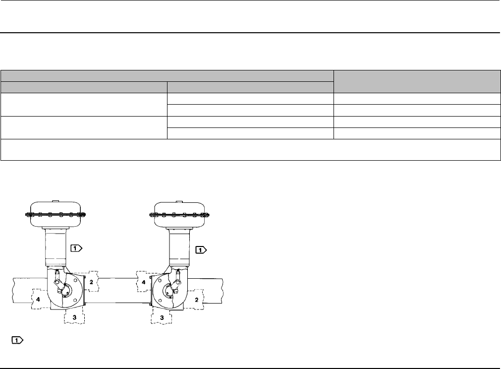
Figure 10. Actuator Housing Construction Styles and Mounting Positions
DESIRED ACTION OF HOUSING CONSTRUCTION TO SPECIFY
Actuator Operated Equipment
Push Down to Open(1) (PDTO) Clockwise to Close(3) Style A
Counterclockwise to Close(3) Style B
Push Down to Close(2) (PDTC) Clockwise to Close(3) Style B
Counterclockwise to Close(3) Style A
1. This action uses the spring to close the valve body or other equipment.
2. This action uses the spring to open the valve body or other equipment.
3. When viewed from actuator side of valve body or other equipment.
STYLE A STYLE B
POSITION 1
STANDARD POSITION 1
STANDARD
NOTE:
DOTTED LINES INDICATE ALTERNATE MOUNTING POSITIONS 2, 3, AND 4.
43A6505-A
A1578-3
11. Apply thread-locking adhesive (high strength) (key 77) to the threads of the cap screw (key 18).
12. Connect the lever (key 27) and the rod end bearing (key 17) with the cap screw and hex nut (keys 18 and 19).
Tighten the cap screw to the torque value listed in table 11.
13. If a positioner is to be used, consult the separate positioner instruction manual for proper positioner installation.
14. Coat the bearing surfaces of the hub (key 29) and cover (key 33) with lithium grease (key 76). Install the bearing
(key 31) and hub into the cover. Secure with the retaining ring (key 30).
15. Install the travel indicator scale (key 35) so that the markings on the scale and cover that were made in step 5 of
the Disassembly procedure are oriented correctly. Securethetravelindicatorscaletothecoverwiththe
self-tapping screws (key 36). Then install the travel indicator (key 37), and secure it with the self-tapping screws
(key 38).
16. Position the travel indicator (key 37) so that the markings on the travel indicator and travel indicator scale that
were made in step 3 of the Disassembly procedure are oriented correctly. Then, replace the cover (key 33), and
secure it with the cap screws and washers (keys 34 and 63). If the holes in the cover and housing (key 20) do not
align, use a regulated air source to move the actuator slightly off the up travel stop. If hole alignment cannot be
obtained in this manner, temporarily loosen the cap screws (key 23), and shift the housing slightly. Do not stroke
the actuator while the cover is off. Tighten the cap screws to the torque value listed in table 11.
17. Follow the instructions in the Actuator Mounting section for correct actuator mounting and adjustment.
Remember to replace the access plate (key 59) when performing this procedure.

Instruction Manual
D100320X012
1051 and 1052 H & J Actuators
October 2012
22
Changing Actuator Mounting
The actuator is normally positioned vertically in a horizontal pipeline. However, each style can be mounted in two
possible mounting styles and four possible positions (see figure 10 ).
Note
Due to its weight, the 1052, size 70 actuator must be externally supported if mounted in the horizontal position.
WARNING
Before performing any Actuator Mounting steps, follow the steps in the WARNING at the beginning of the Maintenance
section.
Use the following procedures along with figures 12 and 13 for key number references to convert from style A to style B
or vice versa or to change the mounting position.
Changing Styles
1. Unscrew the cap screws and washers (keys 34 and 63), and remove the cover (key 33).
2. Heat the hex nut (key 19) to 177_C(350_F) long enough for the thread-locking adhesive (high strength) (key 77) to
lose its holding strength. Then, remove the cap screw and hex nut (keys 18 and 19).
3. Loosen the cap screw (key 28).
CAUTION
If necessary, use a wheel puller to remove the lever (key 27) from the output shaft (key 87). It is permissible to tap the
wheel puller screw lightly to loosen the lever, but hitting the screw with excessive force could damage the operated
equipment.
4. Mark the side of the lever (key 27) that is nearest to the end of the output shaft (key 87). This marking is used during
reassembly to determine which side of the lever should be inserted into the actuator housing first. When the lever is
marked, remove the lever.
5. For an actuator with a J mounting adaptation,
a. Unscrew the cap screws (key 23), and remove the actuator housing (key 20) from the mounting bracket (key 22).
b. Rotate the actuator housing 180 degrees, maintaining the appropriate position (1, 2, 3, or 4), and place the
actuator onto the mounting bracket (key 22).
c. Secure the actuator housing to the mounting bracket with the cap screws (key 23). Tighten the cap screws to the
torque value listed in table 11.

Instruction Manual
D100320X012
1051 and 1052 H & J Actuators
October 2012
23
6. For an actuator with an H mounting adaptation,
a. Unscrew the cap screws (key 78) and remove the actuator assembly from its mounting bracket.
b. Unscrew the cap screws (key 23) and remove the mounting plate (key 22) and output shaft (key 87) assembly
fromtheactuatorhousing.Remounttheassemblyontheoppositesideoftheactuator,andsecureittothe
housingwiththecapscrews(key23).Tightenthecapscrewstothetorquevaluelistedintable11.
c. Rotate the actuator housing 180 degrees, maintaining theappropriateposition(1,2,3,or4)andsecurethe
actuator housing to the mounting bracket with the cap screws (key 78). Tighten the cap screws to the torque
value listed in table 4.
7. Install the lever (key 27) as follows:
a. For push-down-to-open action, rotate the operated equipment to the fully closed position.
b. For push-down-to-close action, rotate the operated equipment to the fully open position.
c. With the operated equipment oriented correctly, slide the lever onto the output shaft (key 87) with the end
marked in step 4 inserted first. When installing the lever, align the bolt holes in the lever as close as possible with
the hole in the rod end bearing (key 17).
d. Temporarily rotate the lever and output shaft until the rod end bearing no longer interferes with further
installation of the lever. Then, slide the lever as far as it can go onto the output shaft. Clamp the lever to the
output shaft with the cap screw (key 28). Tighten the cap screw to thetorquevaluelistedintable11.
e. Rotate the lever and output shaft back to the original position (i.e., operated equipment fully closed for
push-down-to-open action or operated equipment fully open for push-down-to-close action). Then, adjust the
rod end bearing so that it can be attached to the lever.
8. Apply thread-locking adhesive (high strength) (key 77) to the threads of the cap screw (key 18).
9. Connect the lever (key 27) and the rod end bearing (key 17) with the cap screw and hex nut (keys 18 and 19). This
connection can be aided by stroking the actuator from its up travel stop with a regulated air source. Tighten the cap
screw to the torque value listed in table 11.
10. Note the position of the valve body or other operated equipment and direction of rotation. Position the travel
indicator (key 37) accordingly. Replace the cover (key 33), and secure it with the cap screws and washers (keys 34
and 63). If the holes in the cover and housing (key 20) do not align, use a regulated air source to move the actuator
slightly off the up travel stop. If hole alignment cannot be obtained in this manner, temporarily loosen the cap
screws (key 23), and shift the housing slightly. Do not stroke the actuator while the cover is off. Tighten both sets of
cap screws to the torque values listed in table 11.
11. Follow the instructions in the Turnbuckle Adjustment section.
Changing Positions
1. Unscrew the cap screws and washers (keys 34 and 63), and remove the cover (key 33).
2. Mark the orientation of the lever (key 27) with respect to the output shaft (key 87). This marking is used during
reassembly to allow for proper lever/output shaft positioning. When the lever and output shaft are properly
marked, heat the hex nut (key 19) to 177_C(350_F) long enough for the thread-locking adhesive (high strength)
(key 77) to lose its holding strength. Then, remove the cap screw and hex nut (keys 18 and 19).
CAUTION
If necessary, use a wheel puller to remove the lever (key 27) from the output shaft (key 87). You may tap the wheel puller
screw lightly to loosen the lever, but hitting the screw with excessive force could damage the operated equipment.

Instruction Manual
D100320X012
1051 and 1052 H & J Actuators
October 2012
24
3. Loosen the cap screw (key 28) and remove the lever (key 27) from the output shaft (key 87).
4. For an actuator with a J mounting adaptation.
a. Unscrew the cap screws (key 23), and remove the actuator housing (key 20) from the mounting bracket (key 22).
b. Rotate the actuator housing to the new position (1, 2, 3, or 4).
c. Secure the actuator housing to the mounting bracket with the cap screws (key 23). Tighten the cap screws to the
torque value listed in table 11.
5. For an actuator with an H mounting adaptation.
a. Unscrew the cap screws (key 78) and loosen the actuator assembly from its mounting bracket.
b. Rotate the actuator housing to the new position (1, 2, 3, or 4).
c. Secure the actuator housing to the mounting bracket with the cap screws (key 78). Tighten the cap screws to the
torque value listed in table 4.
6. Referring to the alignment marks that were made in step 2, install the lever (Key 27) onto the output shaft (key 87)
as follows:
a. If the new actuator position is 90 degrees clockwise from the previous actuator position, install the lever so that
its orientation mark is located 90 degrees clockwise from the mark on the output shaft.
b. If the new actuator position is 90 degrees or 180 degrees counterclockwise from the previous position, install the
lever so that its orientation mark is located either 90 degrees (for 90 degrees) or 180 degrees (for 180 degrees)
counterclockwise (respectively) from the mark on the output shaft.
c. Slide the lever onto the output shaft with the bolt holes in the lever aligned as closely as possible with the hole in
the rod end bearing (key 17). Then, temporarily rotate the lever and output shaft until the rod end bearing no
longer interferes with further installation of the lever, and slide the lever as far as it can go onto the output shaft.
Clamp the lever to the output shaft with the cap screw (key 28). Tighten the cap screw to the torque value listed
in table 11.
d. Rotate the lever and output shaft back to the original position, and then adjust the rod end bearing so that it can
be attached to the lever.
7. Apply thread-locking adhesive (high strength) (key 77) to the threads of the cap screw (key 18).
8. Connect the lever (key 27) and the rod end bearing (key 17) with the cap screw and hex nut (keys 18 and 19). This
connection can be aided by stroking the actuator from its up travel stop with a regulated air source. Tighten the cap
screw to the torque value listed in table 11.
9. Note the position of the valve body or other operated equipment and direction of rotation. Position the travel
indicator (key 37) accordingly. Replace the cover (key 33), and secure it with the cap screws and washers (keys 34
and 63). If the holes in the cover and housing (key 20) do not align, use a regulated air source to move the actuator
slightly off the up travel stop. If hole alignment cannot be obtained in this manner, temporarily loosen the cap
screws (key 23), and shift the housing slightly. Do not stroke the actuator while the cover is off. Then, tighten both
sets of cap screws to the torque values listed in table 11.
10. Follow the instructions in the Turnbuckle Adjustment section.
Instruction Manual
D100320X012
1051 and 1052 H & J Actuators
October 2012
25
Figure 11. Travel Stop Orientation
SIZES 30 AND 40
SIZES 60 AND 70
A2534-1
Top-Mounted Handwheels and Adjustable Travel Stops
Handwheel and Travel Stop Operation
Note
If repeated or daily manual operation is expected or desired, the unit should be equipped with a manual handwheel actuator. Refer
to the separate manual handwheel actuator instruction manual for mounting instructions.
The top-mounted handwheel assembly is attached to a special upper diaphragm casing (key 1, figures 12 and 13) with
cap screws (key 141, figure 15). A hex nut (key 137, figure 15) locks the handwheel in position.
Turning the handwheel (key 51, figure 15) clockwise into the upper diaphragm casing forces the pusher (key 135,
figure 15) against the diaphragm and diaphragm plate (keys 3 and 4, figures 12 and 13) to compress the spring (key
11, figures 12 and 13) and move the diaphragm rod downward. Turning the handwheel counterclockwise allows the
actuator spring to move the diaphragm rod upward. If the action is push-down-to-close, full opening can be restricted
by positioning the handwheel at the desired position. If the action is push-down-to-open, full closing can be restricted
by use of the handwheel.

Instruction Manual
D100320X012
1051 and 1052 H & J Actuators
October 2012
26
The adjustable up travel stop (figure 16) limits the actuator stroke in the upward direction. To make adjustments, first
relieve actuator loading pressure before removing the closing cap (key 187) as it is a pressure retaining part. Also, for
size 70 actuators, the hex nut (key 137) must be loosened.
Turning the stem (key 133) clockwise into the diaphragm case moves the actuator stem downward or
counterclockwise to allow the spring to move the actuator stem upward. If the action is push-down-to-close, full
opening can be restricted; or if the action is push-down-to-open, full closing can be restricted by the position of the
adjustable travel stop.
The adjustable down travel stop (figure 17) limits the actuator stroke in the downward direction. To make
adjustments, first relieve actuator loading pressure before removing the closing cap (key 187) as it is a pressure
retaining part. After removing the closing cap, loosen the hex jam nut (key 189) and either turn the hex nut (key 63 for
size 40, and 70 actuators; or key 54 for size 60 actuators) down on the stem (key 133) to limit travel, or up on the stem
to allow more travel. Lock the jam nut against the hex nut and replace the closing cap after the adjustment has been
made. For size 70, tighten the hex nut and replace the closing cap after adjustment.
Handwheel and Travel Stop Maintenance
WARNING
Avoid personal injury or property damage from sudden release of process pressure or uncontrolled movement of parts.
Before performing any maintenance operations:
DDo not remove the actuator from the valve while the valve is still pressurized.
DAlways wear protective gloves, clothing, and eyewear when performing any maintenance operations to avoid personal
injury.
DDisconnect any operating lines providing air pressure, electric power, or a control signal to the actuator. Be sure the
actuator cannot suddenly open or close the valve.
DUse bypass valves or completely shut off the process to isolate the valve from process pressure. Relieve process pressure
from both sides of the valve. Drain the process media from both sides of the valve.
DVent the power actuator loading pressure and relieve any actuator spring precompression.
DUse lock-out procedures to be sure that the above measures stay in effect while you work on the equipment.
DThe valve packing box may contain process fluids that are pressurized, even when the valve has been removed from the
pipeline. Process fluids may spray out under pressure when removing the packing hardware or packing rings, or when
loosening the packing box pipe plug.
DCheck with your process or safety engineer for any additional measures that must be taken to protect against process
media.
If loading pressure seems to be leaking from either the handwheel or adjustable up stop, the O-rings (key 138 and 139,
figures 15 and 16) may need replacement. If the adjustable down stop leaks, the O-ring (key 139, figure 17) may need
replacement or possibly the closing cap (key 187, figure 17) is not tight. To tighten the closing cap, apply a good grade
of thread sealant to the closing cap threads.
For ease of operation, the stem (key 133, figures 15, 16, and 17) threads may need an occasional application of lithium
grease. A grease fitting (key 169, figures 15 and 16) is provided for this purpose in the size 70. The size 70 may also
need to have the thrust bearing (key 175, figures 15 and 16) packed with lithium grease. Travel stops for the smaller
casings can be lubricated between the stem and pusher (key 135, figures 15 and 16) with lithium grease.
1. Bypass the control valve, reduce loading pressure to atmospheric, and remove the tubing or pipe from the body
(key 142, figures 15, 16, and 17).

Instruction Manual
D100320X012
1051 and 1052 H & J Actuators
October 2012
27
WARNING
To avoid personal injury from the precompressed spring force thrusting the upper diaphragm casing (key 1, figures 12 and
13) away from the actuator, either relieve 1052 spring compression, or carefully remove 1051 casing cap screws by
following the instructions that are referenced in the steps below before removing the casing.
2. Relieve all actuator spring compression by following the procedures presented in the Disassembly portion of the
Maintenance section. Then, rotate either the handwheel (key 51, figure 15) or the travel stop stem (key 133, figures
16 and 17) counterclockwise until the handwheel or travel stop assembly is no longer compressing the spring.
3. Proceed as appropriate:
For Top-Mounted Handwheels and Adjustable Up Travel Stops
a. Remove the upper diaphragm casing (key 1, figures 12 and 13) by following steps 1, 3, 6, 7, 9, 11, and 12 of the
Disassembly portion of the Maintenance section.
b. Remove the cap screws (key 141, figures 15 and 16, and separate the assembly from the upper casing.
c. Loosenthelocknut(key137,figure15)orremovetheclosingcap(key187,figure16).
d. Turn the stem (key 133, figures 15 and 16) clockwise out of the body. On handwheel assemblies, the cotter pen
and slotted nut (keys 247 and 54, figure 15) will have to be removed so that the handwheel (key 51, figure 15)
andlocknutcanbetakenoffthestemfirst.
e. Remove and inspect the O-rings (keys 138 and 139, figures 15 and 16); replace them if necessary.
f. To complete disassembly for sizes 40 and 60, drive out thegroovepin(key140,figures15and16),andslidethe
pusher (key 135, figures 15 and 16) off the stem. The pusher of a size 70 unit is held to the stem by a retaining
screw (key 174, figures 15 and 16). Removing the retaining screw and pusher exposes the thrust bearing (key
175, figures 15 and 16) for inspection.
For Adjustable Down Travel Stops
Refer to figure 17 for appropriate key numbers unless otherwise stated.
a. Remove the closing cap (key 187), and unscrew the jam nut and hex nut (keys 189 and 63 for sizes 40, and 70
actuators; or keys 189 and 54 for size 60 actuators) off the stem (key 133).
b. Remove the upper diaphragm casing (key 1, figures 12 and 13) and travel stop body (key 142) by following steps
1, 3, 6, 7, 9, 11, and 12 of the Disassembly portion of the Maintenance section.
c. Unscrew cap screws (key 141), and remove the body from the diaphragm case.
d. Check the condition of the O-ring (key 139), and replace it if necessary.
e. Loosen the hex nut (key 54), and then unscrew the travel stop stem (key 133) out of the actuator stem. The
lower diaphragm plate (key 82) can now be removed and the rest of the actuator disassembled.
4. Reassemble by reversing the order of the steps you took to disassemble, being sure to apply lubricant as previously
mentioned and as shown by the lubrication boxes (key 241) in figures 15 and 16. For size 70 handwheels or up
travel stop assemblies, coat the threads of the retaining screws (key 174, figures 15 and 16) with thread-locking
adhesive (high strength) (key 242).

Instruction Manual
D100320X012
1051 and 1052 H & J Actuators
October 2012
28
5. Adjust the spring to obtain the appropriate travel stop restriction by following the procedures presented in the
introductory portion of this section, and then return the unit to operation.
Parts Ordering
When corresponding with your Emerson Process Management sales office about this equipment, refer to the serial
number found on the actuator nameplate (key 41, figure 12). Also, specify the complete 11-character part number
from the following parts list when ordering replacement parts.
WARNING
Use only genuine Fisher replacement parts. Components that are not supplied by Emerson Process Management should
not, under any circumstances, be used in any Fisher valve, because they may void your warranty, might adversely affect the
performance of the valve, and could cause personal injury and property damage.
Parts List
Retrofit Kits
Kit provides parts to add a top-mounted handwheel.
Kit number 1 includes the handwheel assembly only.
Kit number 2 includes Kit number 1 and a new upper
case (key 1) that is required to mount the handwheel
assembly.
Key Description Part Number
1052 Actuator
Kit Number 1
Size 40 38A1213X032
Size 60, Push-Down-to-Close 38A1213X062
Size 60, Push-Down-to-Open 38A1213X052
Kit Number 2
Size 40 38A1213X072
Size 60, Push-Down-to-Close 38A1213X022
Size 60, Push-Down-to-Open 38A1213X042
1052 Actuator
Kit Number 1
Size 40 38A1213X032
Size 60, Push-Down-to-Close 38A1213X062
Size 60, Push-Down-to-Open 38A1213X052
Size 70 CV8010X0012
Kit Number 2
Size 40 38A1213X072
Size 60, Push-Down-to-Close 38A1213X022
Size 60, Push-Down-to-Open 38A1213X042
Size 70 CV8010X0022
Common Parts
(figures 12 and 13)
Note
Part numbers are shown for recommended spares only. For part
numbers not shown, contact your Emerson Process Management sales
office.
Note
The size 70 actuator is available only in 1052 actuators.
Key Description Part Number
1 Casing, upper
2 Diaphragm Casing, Lower
3* Diaphragm
Molded Nitrile/Nylon
Std, w/handwheel, or w/adj up stop
Size 40 2E670002202
Size 60 2E859702202
Size 70 2N126902202
w/adj down stop
Size 40 2E669902202
Size 60 2E859802202
Size 70 2N130902202
Molded Silicone/Polyester
Std, w/handwheel, or w/up stop
Size 40 2E6700X0012
Size 60 2E8597X0032
Size 70 2N1269X0012
w/down stop
Size 40 2E6699X0042
Size 60 2E8598X0012
Size 70 2N1309X0012
4 Diaphragm Head
*Recommended spare parts
Instruction Manual
D100320X012
1051 and 1052 H & J Actuators
October 2012
29
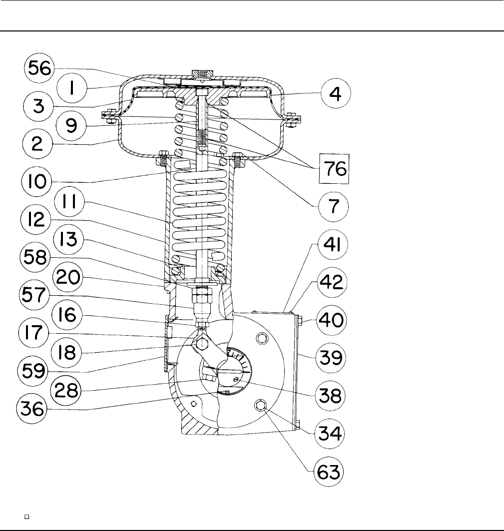
Figure 12. Fisher 1051 Actuator with Typical H and J Mounting Adaptations
D0299-1
SIDE VIEW
1051 ACTUATOR
NOTES:
1. KEYS 12 AND 21 ARE NOT REQUIRED FOR SIZE 30 ACTUATORS.
2. KEYS 56, 82, 78, AND 92 ARE NOT SHOWN.
APPLY LUBRICANT / SEALANT
Key Description Part Number
5Screw,Cap,Hexhd
Size 40 (16 req'd)
Size 60 (24 req'd)
Size 70 (28 req'd)
6Nut,hex
Size 40 (16 req'd)
Size 60 (24 req'd)
Size 70 (28 req'd)
Key Description Part Number
7 Screw, cap, Hex hd
Size 40 (4 req'd)
Size 60 (6 req'd)
Size 70 (10 req'd)
8TravelStop(2req'd)
9 Screw, cap, Hex socket
10 Diaphragm Rod
11 Spring See following table
12 Spring barrel
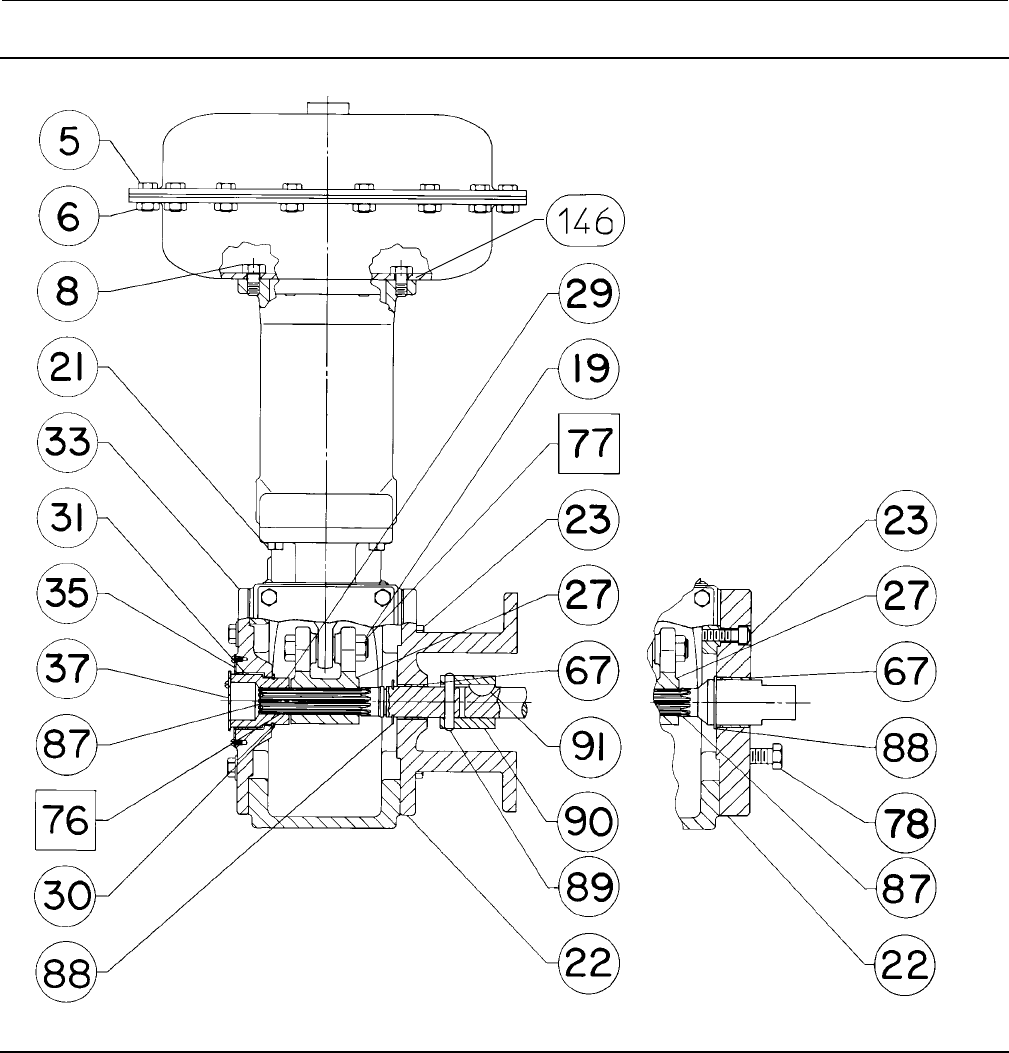
Instruction Manual
D100320X012
1051 and 1052 H & J Actuators
October 2012
30
Figure 12. Fisher 1051 Actuator with Typical H and J Mounting Adaptations (continued)
59A2408-B
D0299-2
FRONT VIEW
STYLE J MOUNTING ADAPTATION FRONT VIEW
STYLE H MOUNTING ADAPTATION
59A2406-B
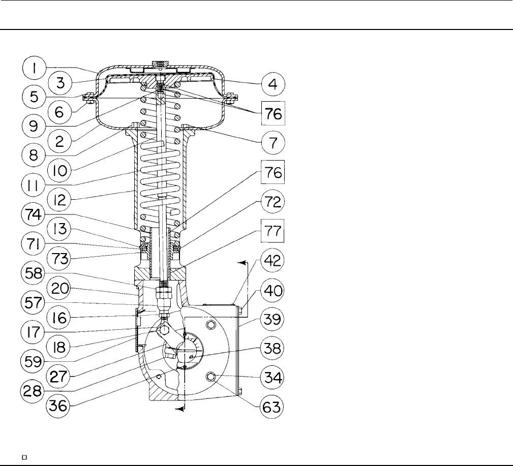
Instruction Manual
D100320X012
1051 and 1052 H & J Actuators
October 2012
31
Figure 13. Fisher 1052 Actuator with Typical H and J Mounting Adaptations
59A2420-A
D0300-1
SIDE VIEW
1052 ACTUATOR
A
A
NOTES:
1. KEYS 56, 82, 78, AND 92 ARE NOT SHOWN.
APPLY LUBRICANT / SEALANT
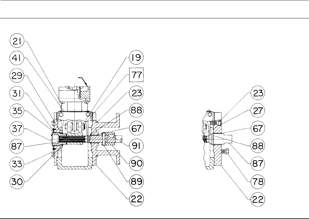
Instruction Manual
D100320X012
1051 and 1052 H & J Actuators
October 2012
32
Figure 13. Fisher 1052 Actuator with Typical H and J Mounting Adaptations (continued)
59A2420-A
59A2416-A
SECTION A-A
STYLE J MOUNTING ADAPTATION FRONT VIEW DETAIL
STYLE H MOUNTING ADAPTATION
SEE VIEW B
Key Description Part Number
13 Spring seat See following table
16 Nut, hex
17 Bearing, Rod End
18 Screw, cap, Hex hd
19 Nut, Hex, Jam
20 Housing
21 Screw, Cap, Hex Hd (4 req'd)
22 Plate, mounting
23 Screw, Cap, Hex socket (4 req'd)
27 Lever
28 Screw cap, Hex Hd
29 Hub
30 Retaining Ring, Ext
31* Bushing (2 req'd)
Size 40 12A9373X012
Sizes 60 & 70 12A9374X012
33 Cover
34 Screw, Cap, Hex Hd
34 Stud post, Steel (not shown)(w/ 3555T)(4 req'd)
35 Scale, Indicator (w/out handwheel or w/ 3555T)
36 Screw, Self Tap (2 req'd)
37 Travel Indicator
38 Self-Tapping Screw (2 req'd)
38 Machine Screw (2 req'd)
39 Plate, Cover
w/o 3610J/3620J Positioner
Key Description Part Number
40 Screw, Cap, Hex hd
w/o 3610J/3620J Positioner (4 req'd)
41 Nameplate
42 Screw, Drive (4 req'd)
56 Nameplate
57 Turnbuckle
58 Nut, Hex, Jam
59 Plate, Access
63 Washer, Plain
1051 w/TopWorx™ DXP M21GNEB or 4200
Size 40 (4 req'd)
Sizes 60 & 70 (2 req'd)
64 Ind, Travel (not shown)(w/ 3555T)
65 Screw, Mach, Fill hd (w/ 3555T)
66 Disc, Travel Indicator (w/ 3555T) (not shown)
67* Bushing, PTFE
Style H Mounting
w/22.2 mm (7/8-inch)
Actuator output shaft 12A9557X012
w/28.6 mm (1-1/8 inch)
Actuator output shaft 12A9775X012
w/38.1 mm (1-1/2 inch)
Actuator output shaft 12A9559X012
Style J Mounting
Size 40
w/9.5 & 12.7 mm (3/8 & 1/2-inch)
Actuator output shaft 12A9555X012
*Recommended spare parts
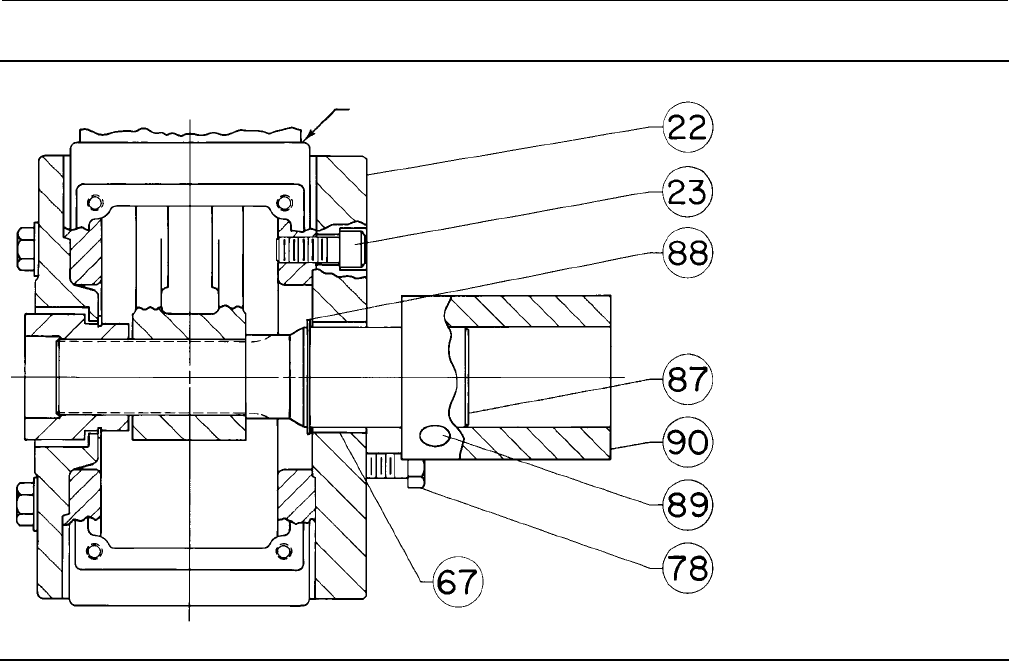
Instruction Manual
D100320X012
1051 and 1052 H & J Actuators
October 2012
33
Figure 14. H Mounting for 44.5 or 50.8 mm (1-3/4 or 2-Inch) Keyed Equipment Shafts
39A2401-A
A3245-1
ACTUATOR
HOUSING
Key Description Part Number
w/15.9 mm (5/8-inch) output shaft 12A9555X012
Sizes 40 & 60
w/19.1 & 25.4 mm (3/4 & 1-inch)
Actuator output shaft 12A9775X012
Sizes 60 & 70
w/31.8 & 38.1 mm (1-1/4 & 1-1/2 inch)
Actuator output shaft 12A9559X012
w/50.4 mm (2-inch)
Actuator output shaft 12A9715X012
71 Bearing, Thrust, Steel (1052)
72 Bearing race, Steel (1052) (2 req'd)
73 Bearing Seat (1052, Sizes 60 & 70)
74 Screw, adjusting (1052)
76 Lithium Grease (not furnished w/actuator)
77 Thread Locking Adhesive (High Strength)
(not furnished w/actuator)
78 Cap Screw, Hex Hd
Style H
Size 40
w/22.2 mm (7/8-inch) actuator output shaft (4 req'd)
w/28.6 mm (1-1/8 inch) actuator output shaft (4 req'd)
w/38.1 mm (1-1/2 inch) actuator output shaft (4 req'd)
Size 60
w/28.6 mm (1-1/8 inch) actuator output shaft (4 req'd)
w/38.1 mm (1-1/2 inch) actuator output shaft (4 req'd)
Style J
Size 30/40
w/9.5 mm (3/8-inch) actuator output shaft (2 req'd)
w/12.7 mm (1/2-inch) actuator output shaft (2 req'd)
Key Description Part Number
w/15.9 mm (5/8-inch) actuator output shaft (4 req'd)
Size 40
w/19.1 mm (3/4-inch) actuator output shaft (4 req'd)
w/25.4 mm (1-inch) actuator output shaft (4 req'd)
Size 60
w/19.1 mm (3/4-inch) actuator output shaft (4 req'd)
w/25.4 mm (1-inch) actuator output shaft (4 req'd)
w/31.8 mm (1-1/4 inch) actuator output shaft (4 req'd)
w/38.1 mm (1-1/2 inch) actuator output shaft (4 req'd)
w/50.4 mm (2-inch) actuator output shaft
for 44.5 mm (1-3/4 inch) keyed equipment shaft (1 req'd)
for 50.4 mm (2-inch) keyed equipment shaft (1 req'd)
82 Diaphragm head, lower (1051 w/adj down stop)
83 Plug, protective polyethylene (1052 Size 70)
87 Actuator Output Shaft
88 Retaining Ring
89* Pin, Groove, Steel Alloy
Style J
Size 40
w/9.5 mm (3/8-inch)
actuator output shaft 19A1658X012
w/12.7 mm (1/2-inch)
actuator output shaft 19A1658X012
w/15.9 mm (5/8-inch)
actuator output shaft 19A1658X012
w/19.1 mm (3/4-inch)
actuator output shaft G1232232992
w/25.4 mm (1-inch)
actuator output shaft G1232232992
Size 60
*Recommended spare parts
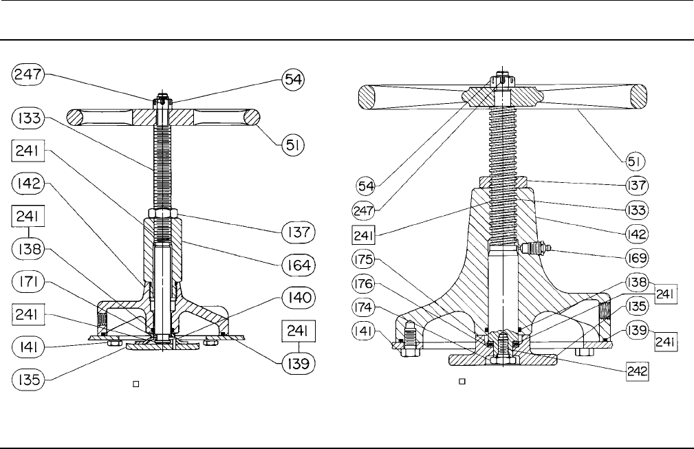
Instruction Manual
D100320X012
1051 and 1052 H & J Actuators
October 2012
34
Figure 15. Top-Mounted Handwheel Assemblies
38A1213-B CV8010-E
TOP-MOUNTED HANDWHEEL ASSEMBLY FOR
SIZE 30, 40, AND 60 ACTUATORS TOP-MOUNTED HANDWHEEL ASSEMBLY FOR
SIZE 70 ACTUATORS
APPLY LUB APPLY LUB / SEALANT
Key Description Part Number
w/19.1 mm (3/4-inch)
actuator output shaft G1232232992
w/25.4 mm (1-inch)
actuator output shaft G1232232992
Style J
Size 60
w/38.1 mm (1-1/2 inch)
Actuator Output Shaft G1232332992
Sizes 60 & 70
w/50.4 mm (2-inch) actuator output shaft
for 44.5 mm (1-3/4 inch) keyed
equipment shaft H1361632992
for 50.4 mm (2-inch) keyed
equipment shaft H1361632992
90 Coupling
91* Key, Woodruff See following table
92 Spacer, steel (not shown) (2 req'd)
Sizes 60 & 70 Style J
w/38.1 mm (1-1/2 inch) actuator output shaft
w/31.8 mm (1-1/4 inch) actuator output shaft
- - - Bushing, Pipe (not shown) (1052 Size 70)
146 Spacer (1 req'd)
Top-Mounted Handwheel (figure
15)
Key Description Part Number
51 Handwheel
54 Hex Nut, Slotted
133 Stem
135 Plate, Pusher
137 HexNut,Jam,Steel
138* O-Ring, Nitrile
Size 40 1D237506992
Size 60 1B885506992
Size 70 1C415706992
139* O-Ring, Nitrile
Size 40 1D267306992
Size 60 1D547106992
Size 70 1D269106992
140 Groove Pin (Sizes 40 & 60)
141 Cap Screw, Hex hd
Size 40 (6 req'd)
Size 60 (8 req'd)
Size 70 (12 req'd)
142 Body
*Recommended spare parts

Instruction Manual
D100320X012
1051 and 1052 H & J Actuators
October 2012
35
Key Description Part Number
164 Body Extension (Sizes 40 & 60)
169 GreaseFitting(Size70)
171 Spacer (Size 60)
174 Retaining Screw (Size 70
175 Thrust Bearing (Size 70)
241 Lithium Grease (not furnished w/travel stop)
242 Thread Locking Adhesive (High Strength)
(not furnished w/travel stop)
(1052 Size 70 only)
246 Spacer (Sizes 60 & 70)
247 Pin, Cotter, Stainless Steel
Adjustable Up Travel Stop
(figure 16)
133 Stem
135 Plate, Pusher
137 Nut, Travel Stop (Size 70)
138* O-Ring, Nitrile
Size 40 1D237506992
Size 60 1B885506992
Size 70 1C415706992
139* O-Ring, Nitrile
Size 40 1D267306992
Size 60 1D547106992
Size 70 1D269106992
140* Groove Pin
Size 40 1F118028992
Size 60 1B627035072
141 Cap Screw, Hex Hd, Steel
Size 40 (6 req'd)
Size 60 (8 req'd)
Size 70 (12 req'd)
142 Body
164 Body Extension (Sizes 40 & 60)
169 GreaseFitting,Steel(Size70)
171 Spacer (Size 60)
Key Description Part Number
174 Retaining Screw, Steel (Size 70)
175 Thrust Bearing
176 Bearing Race, Thrust (1052, Size 70) (2 req'd)
187 Travel stop cap (Size 70)
241 Lithium Grease (not furnished w/travel stop)
242 Thread Locking Adhesive (High Strength)
(not furnished w/travel stop)
(1052 Size 70 only)
Adjustable Down Travel Stop
(figure 17)
54 Hex Nut
1051
Size 40 (1 req'd)
Size 60 (2 req'd)
1052
Size 40 (1 req'd)
Sizes 60 & 70 (2 req'd)
63 Flange Nut (Sizes 40 & 70)
133 Travel Stop Stem
134 Washer, Plain
139* O-Ring, Nitrile
Size 40 1D267306992
Size 60 1D547106992
Size 70 1D269106992
141 Cap Screw, Hex hd
Size 40 (6 req'd)
Size 60 (8 req'd)
Size 70 (12 req'd)
142 Travel Stop Body
187 Travel Stop Cap
189 Hex Nut, Jam
Sizes 40 & 60 (1 req'd)
Size 70 (2 req'd)
241 Lithium Grease (not furnished w/travel stop)
*Recommended spare parts

Instruction Manual
D100320X012
1051 and 1052 H & J Actuators
October 2012
36
Key 11 Spring(1), steel (for 1052 actuator only)
CASING
PRESSURE ACTUATOR
SIZE
INITIAL SPRING COMPRESSION KEY 11
SPRING PART
NUMBER
Push-Down-to-Open Push-Down-to-Close
Bar Psig Bar Psig Bar Psig
0to1.2 0to18
30
0.2
0.2
0.3
2.7
3.1
4.3
0.2
0.2
0.2
2.7
3.0
3.0
1F361627032
1K509827032
1N751527032
40 0.2
0.3
3.0
4.3
0.2
0.2
3.0
3.0
1L217427042
1P637127082
60 0.3
0.2
3.7
3.5
0.2
0.2
3.0
3.0
1K162727082
1N937327082
0to2.3 0to33
30
0.3
0.3
0.3
0.2
4.3
3.7
3.9
3.1
0.3
0.2
0.2
0.2
4.2
3.0
3.0
3.0
1N751527032
1F177027092
1F177127092
1F177227092
40
0.3
0.4
0.3
4.3
6.0
4.4
0.3
0.2
0.2
4.3
3.0
3.0
1P637127082
1L217327042
1N844027082
60
0.2
0.5
0.5
3.5
7.0
6.8
0.2
0.2
0.2
3.5
3.0
3.0
1N937327082
1K162827082
1P270227042
70 0.7 10.1 0.2 3.0 1R676027042
0to2.8 0to40
30
0.3
0.3
---
3.7
3.9
---
0.3
0.2
0.2
3.7
3.0
3.0
1F177027092
1F171127092
1F177227092
40 0.3
0.4
4.4
6.0 0.2 3.0
3.0
1N844027082
1L217327042
60 0.5
0.5
6.8
7.0 0.2 3.0
3.1
1P270227042
1K16287082
70 0.7 10.1 0.2 3.3 1R676027082
0to3.8 0to55
30 0.2 3.1 0.2 3.1 1F177227092
40 0.3 4.4 0.2 3.5 1N844027082
70 0.7 10.1 0.7 10.1 1R676027082
0.2 to 1.0 3to15
30 --- --- 0.2 3.0 1K509827032
40 --- --- 0.2 3.0 1L217427042
60 0.3 3.7 0.2 3.0 1K16272082
0.2 to 2.1 3to30
30
---
---
---
0.3
---
---
---
4.3
0.2
0.2
0.2
0.3
3.1
3.0
3.0
4.2
1F177027092
1F177127092
1F177227092
1N751527032
40
0.3
0.4
---
4.3
6.0
---
0.3
0.2
0.2
4.3
3.0
3.0
1P637127082
1L217327042
1N844027082
60
0.2
0.5
---
3.5
7.0
---
0.2
0.2
0.2
3.5
3.0
3.0
1N937327082
1K162827082
1P270227042
70 0.7 10.1 0.2 3.0 1R676027082
1. For more detailed ordering information concerning proper spring selection to obtain the torque required by the valve, consult your Emerson Process Management sales office.
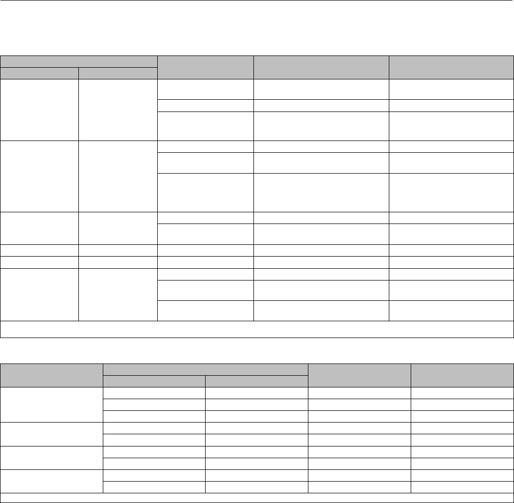
Instruction Manual
D100320X012
1051 and 1052 H & J Actuators
October 2012
37
Key 11 Spring(1), steel (for 1051 actuator only)
Key 13 Spring Seat(1), steel (for 1051 actuator only)
CASING PRESSURE ACTUATOR SIZE KEY 11
SPRING PART NUMBER
KEY 13
SPRING SEAT PART NUMBER
Bar Psig
0to1.2 0to18
30 1K509827032
1F361627032
12A9445X012
12A9445X012
40 1L217427042 12A9447X012
60
1K162727082
1N937327082
1N937327082
12A9450X012
12A9448X012
12A9449X012
0to2.3 0to33
30 1N751527032 12A9445X012
40 1L217327042
1P637127082
12A9446X012
12A9447X012
60
1K162827082
1K162827082
1N937327082
1N937327082
12A9448X012
12A9449X012
12A9448X012
12A9449X012
0to2.8 0to40
40 1L217327042 12A9446X012
60 1K162827082
1K162827082
12A9448X012
12A9449X012
0to3.8 0to55 40 1L217327042 12A9446X012
0.2 to 1.0 3to15 60 1K162727082 12A9450X012
0.2 to 2.1 3to30
30 1N751527032 12A9445X012
40 1L217327042
1P637127082
12A9446X012
12A9447X012
60 1K612827082
1N937327082
12A9449X012
12A9449X012
1. For more detailed ordering information concerning proper spring and spring seat selection to obtain the torque required by the valve, contact your Emerson Process Management sales of
fice.
Key 91*. Woodruff Key for Actuator with J Mounting Adaptation, Alloy Steel
ACTUATOR SIZE KEYED SHAFT COUPLING DIAMETER WOODRUFF KEY NUMBER PART NUMBER
mm Inches
40
9.5 3/8 304 F1357631252
12.7 1/2 304 F1357631252
15.9 5/8 404 F1357731252
40 & 60 19.1 3/4 406 F1357831252
25.4 1607 F1357931252
60 & 70(1) 31.8 1-1/4 809 F1358031252
38.1 1-1/2 811 F1358131252
60 & 70(1) 44.5 1-3/4 1211 F1358231252
50.8 21022-1 F1366131252
1. Size 70 for 1052 actuator only.
*Recommended spare parts
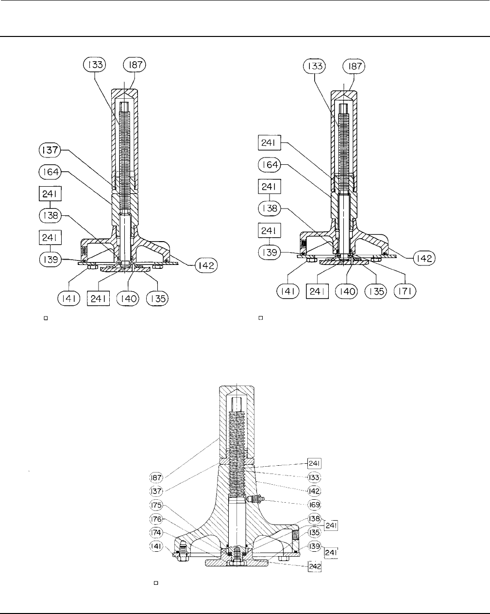
Instruction Manual
D100320X012
1051 and 1052 H & J Actuators
October 2012
38
Figure 16. Adjustable Up Travel Stops
28A1207-B
28A1214-A
CV8057-D/DOC
ADJUSTABLE UP TRAVEL STOP FOR
SIZE 30 AND 40 ACTUATORS
ADJUSTABLE UP TRAVEL STOP FOR
SIZE 60 ACTUATORS
ADJUSTABLE UP TRAVEL STOP FOR SIZE 70
1052 ACTUATORS
APPLY LUB / SEALANT
APPLY LUB APPLY LUB
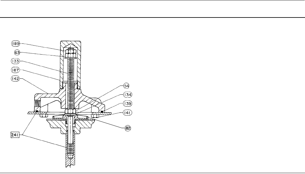
Instruction Manual
D100320X012
1051 and 1052 H & J Actuators
October 2012
39
Figure 17. Adjustable Down Travel Stop
NOTE:
FOR SIZE 60 ACTUATORS, A SECOND HEX NUT (KEY 54) IS USED IN
THE PLACE OF THE HEX NUT (KEY 63)
38B5654-B
A7238

Instruction Manual
D100320X012
1051 and 1052 H & J Actuators
October 2012
40
Emerson Process Management
Marshalltown, Iowa 50158 USA
Sorocaba, 18087 Brazil
Chatham, Kent ME4 4QZ UK
Dubai, United Arab Emirates
Singapore 128461 Singapore
www.Fisher.com
The contents of this publication are presented for informational purposes only, and while every effort has been made to ensure their accuracy, they arenot
to be construed as warranties or guarantees, express or implied, regarding the products or services described herein or their use or applicability. All sales are
governed by our terms and conditions, which are available upon request. We reserve the right to modify or improve the designs or specifications of such
products at any time without notice.
E1984, 2012 Fisher Controls International LLC. All rights reserved.
Fisher, FISHTAIL, and TopWorx are marks owned by one of the companies in the Emerson Process Management business unit of Emerson Electric Co.
Emerson Process Management, Emerson, and the Emerson logo are trademarks and service marks of Emerson Electric Co. All other marks are the property
of their respective owners.
Neither Emerson, Emerson Process Management, nor any of their affiliated entities assumes responsibility for the selection, use or maintenance
of any product. Responsibility for proper selection, use, and maintenance of any product remains solely with the purchaser and end user.
