Emerson Fisher 2100 Data Sheet
2015-03-30
: Emerson Emerson-Fisher-2100-Data-Sheet-681649 emerson-fisher-2100-data-sheet-681649 emerson pdf
Open the PDF directly: View PDF ![]() .
.
Page Count: 8
www.Fisher.com
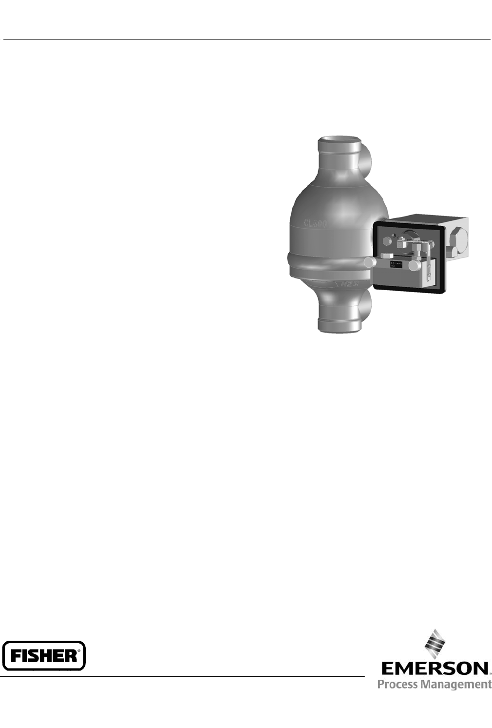
Fisherr 2100 Pneumatic and 2100E Electric
Liquid Level Switches
Fisher 2100 on-off pneumatic switch and 2100E
electric switch sense (shown in figure 1) high or low
liquid levels. Typically, these switches pneumatically or
electrically operate safety shutdown systems for field
processing equipment in oil and gas production
applications. 2100 and 2100E switches both use a
displacer‐style sensor located in an external cage that
mounts on the outside of a vessel.
Unless otherwise noted, all NACE references are to
NACE MR0175-2002.
Features
n Proven Rugged Construction—The switch is isolated
and sealed from the process through a
corrosion‐resistant displacer and torque tube
assembly for maximum reliability. The displacer can
withstand up to 1‐1/2 times the maximum working
pressure, allowing it to remain in the cage during
hydrostatic testing.
n Sour Service Capability—Materials are available for
applications handling sour fluids and gases. These
constructions comply with the metallurgical
requirements of NACE MR0175‐2002.
Environmental restrictions may apply.
n Application Versatility—The 2100 and 2100E switch
construction comes in a left‐hand as well as a
right‐hand mounting version. The explosion‐proof,
hermetically sealed 2100E switch is offered as both
a factory mounting and as an electric switch retrofit
to the proven 2100 switch.
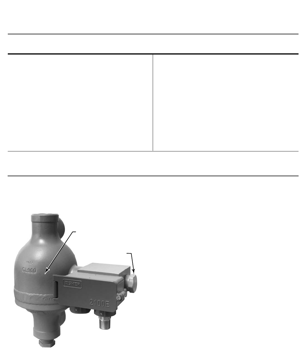
FISHER 2100 PNEUMATIC LIQUID LEVEL SWITCH
n Installation Versatility—The displacer cage has two
1 NPT pipe plugs that you can remove and relocate
for horizontal instead of vertical equalizing piping,
or for installation of a bleed or drain valve.
n Easy Reversibility—Switching action for both the
2100 and 2100E switches is field‐reversible from
high‐level to low‐level or vice versa without
additional parts.
2100 and 2100E Level Switches
D200032X012
Product Bulletin
32.2:2100
February 2014

2100 and 2100E Level Switches
D200032X012
Product Bulletin
32.2:2100
February 2014
2
Specifications
Input Signal
Liquid level
Minimum Process Liquid Specific Gravity
0.5 (consult your Emerson Process Management sales
office for specific gravities below this value)
Output Signal
2100: Equal to the supply pressure when the switch is
in the normal position (flapper against nozzle) and
reduced to approximately atmospheric pressure,
depending upon the bleed orifice size and the piping
configuration, when the switch is activated
2100E: Same as supply signal
Supply Signal
2100: J2.1 to 4.1 bar (30 to 60 psig), J4.1 to
6.9 bar (60 to 100 psig) or J6.9 to 10.3 bar (100 to
150 psig)
2100E: 11 amperes, 1/4 horsepower at 125/250 volts
ac; 5 amperes resistive, 3 amperes inductive at 28
volts DC
Supply Medium (2100)
Air or Natural Gas(1)
Steady‐State Air Consumption(2) (2100)
Less than 0.03 normal m3/hour (1.0 scfh) for all
supply pressures when the liquid level is 25.4 mm
(1 inch) below the normal switch position (flapper
against nozzle) for high‐level switching or 25.4 mm
(1 inch) above the normal switch position for
low‐level switching
Maximum Working Pressure(3)
J153 bar (2220 psig) WOG(4) except J24 bar
(350 psig) WOG is the maximum working pressure for
sight window construction
Operative Temperature Range(3)
2100: –29 to 204_C (–20 to 400_F)
2100E: –29 to 82_C (–20 to 180_F)
Displacer Diameter
102 mm (4 inches)
Process Connection Size
153 bar (2220 psig) WOG(4): J1 NPT internal
JDN 50 (NPS 2) Schedule 80 buttwelding ends, or
JDN 50 (NPS 2) Schedule 160 buttwelding ends
2100 Switch Supply Pressure Connection Size
1/4 NPT internal
2100E Switch Electrical Connection Size
1/2 NPT external
Hazardous Area Classification
Approvals on the electrical switch component in the
2100E, supplied by ITT NEO‐DYN are as follows:
CSA— Class I Division 1, Groups A,B,C,D
Class II Division 1, Groups E,F,G ; Dual Seal
FM— EXP - Class I Division 1 Groups A,B,C,D
DIP - Class II Division 1 Groups E,F,G
UL— Class I Division 1 Groups A,B,C,D
Class II Division 1 Groups E,F,G
ATEX— Ex d IIC
IECEx— Ex d IIC
Approvals on the complete 2100E assembly are as
follows:
Russian GOST-R—1ExdIICT4/T5/T6
Russian FSETAN
Contact your Emerson Process Management sales
office if additional information is required.
Construction Materials
Cage: JSA216 Cast Steel (WCC) cage, JSA216 Cast
Steel (WCC) cage (NACE MR01752002) and JSA351
316 SST (CF8M) cage
Displacer: JS30400 stainless steel (standard)
JS31603 solution annealed stainless steel (NACE
MR0175‐2002)
Torque Rod & Tube Assembly: N05500
Bearing: Glass‐filled PTFE
O‐Rings: Fluorocarbon
Cover Gasket:
2100: Chloroprene
2100E: Silicone rubber
Other Gaskets: Silicone rubber
Nozzle Block Assembly (2100 only): Aluminum &
stainless steel
Nozzle (2100 only): Stainless steel
-continued -
2100 and 2100E Level Switches
D200032X012
Product Bulletin
32.2:2100
February 2014
3
Specifications (continued)
Construction Materials (continued)
Flapper & Clamp Assembly (2100 only): Stainless
steel
Flapper Seat (2100 only): Fluorocarbon
Magnet (2100 only): Special material
Body Block: Steel
Cover:
2100: Clear plastic
2100E: Aluminum
Housing (2100E only): Aluminum
Other Metal Parts: Stainless steel
Options
2100 Switch Option: Individual street tee and bleed
orifice (when it is not desired to supply several level
switches from one common block and bleed
restriction)
Sight Window Option: A sight window is available for
either the 2100 or 2100E that installs in place of the
pipe plug, as illustrated in figure 1.
NACE Option: Constructions are available which
comply with the metallurgical requirements of NACE
MR0175‐2002. Environmental restriction may apply.
Shipping Weights
17.2 kg (38 pounds)
NOTE: Specialized instrument terms are defined in ANSI/ISA Standard 51.1 - Process Instrument Terminology.
1. Natural gas should contain no more than 20 ppm of H2S.
2. Normal m3/‐‐normal cubic meters per hour at 0_C, 1.01325 bar, absolute (Scfh‐‐standard cubic feet per hour at 60_F, 14.7 psia)
3. Pressure and temperature limits in this document and any applicable standards or code limitations should not be exceeded.
4. Water, Oil, Gas maximum working pressure. Corresponds to Cold Working Pressure: the maximum pressure rating allowed under normal ambient temperature conditions, which are usually
understood to be -29 to 38_C (-20 to 100_F). Refer to MSS SP‐25.
APPROXIMATE
SWITCHING POINT
LOCATION OF
OPTIONAL
SIGHT WINDOW
X0682
Figure 1. Fisher 2100E Electric Liquid Level Switch Principle of Operation
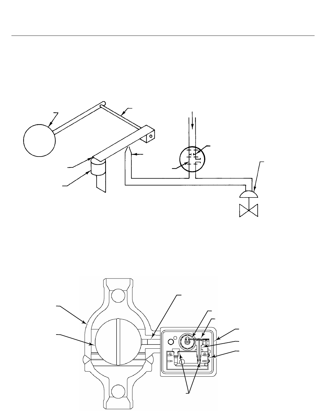
Figure 2 shows the 2100 switch with the nozzle,
flapper, and magnet positioned for high level
activation. When the switch is in the normal position
with the flapper against the nozzle, output pressure
cannot bleed off and remains the same as full supply
pressure. Rising liquid level exerts a buoyant force on
the displacer, producing a torque on the torque tube.
When the torque transmitted by the torque tube
exceeds the torque exerted on the flapper by the
magnet, the flapper snaps away from the nozzle,
allowing output pressure to bleed through the nozzle
faster than supply pressure can enter through the
bleed orifice. The reduced pressure in the output
signal line activates the shutdown or alarm system.
When the liquid level lowers, the falling displacer
forces the flapper into the field of the magnet, letting
the magnet snap the flapper against the nozzle and
causing output pressure to build to full supply
pressure.
2100 and 2100E Level Switches
D200032X012
Product Bulletin
32.2:2100
February 2014
4
Figure 2. Principle of Operation for High‐Level Fisher 2100 Switch
A3619‐2
DISPLACER TORQUE TUBE
FLAPPER
MAGNET
NOZZLE
OPTIONAL
STREET TEE
SUPPLY
OPTIONAL
BLEED ORIFICE
SHUTDOWN
VALVE (OR ALARM
SYSTEM)
OUTPUT SIGNAL
Figure 3. Construction Details of Low‐Level Fisher 2100 Switch
TORQUE TUBE ASSEMBLY
FLAPPER & CLAMP ASSEMBLY
FLAPPER SEAT
GASKET
NOZZLE
NOZZLE BLOCK ASSEMBLY
O‐RINGS
CAGE
DISPLACER
GE59150
2100 and 2100E Level Switches
D200032X012
Product Bulletin
32.2:2100
February 2014
5
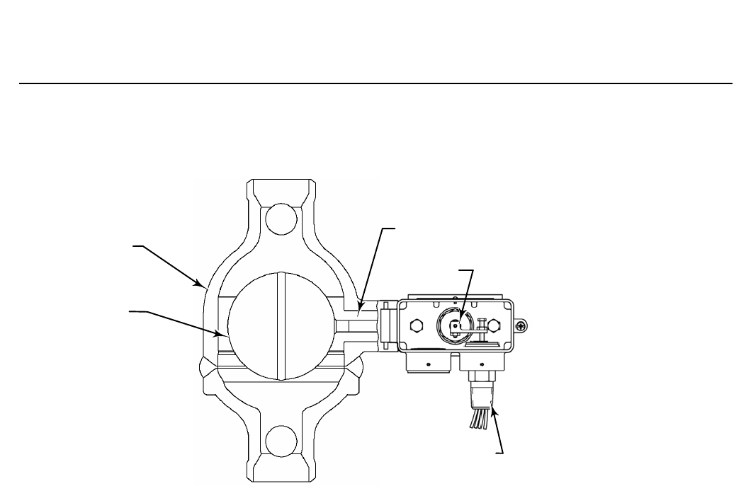
Figure 4. Construction Details of Fisher 2100E Switch
CAGE
DISPLACER
ELECTRIC
SWITCH ASSEMBLY
TORQUE TUBE
ASSEMBLY
SWITCH ARM
GE59290
40B6593
Figure 3 shows a sectional view of the 2100 switch
positioned for low level activation. The nozzle, flapper,
and magnet are on the opposite side of the torque
tube, so that downward displacer travel moves the
flapper away from the nozzle.
With the 2100E switch (figure 4), rising liquid level
exerts a buoyant force on the torque tube that either
activates or deactivates an electrical SPDT or DPDT
switch depending on the switching action desired.
Falling liquid level deactivates or activates the same
switch depending on the action desired.
Installation
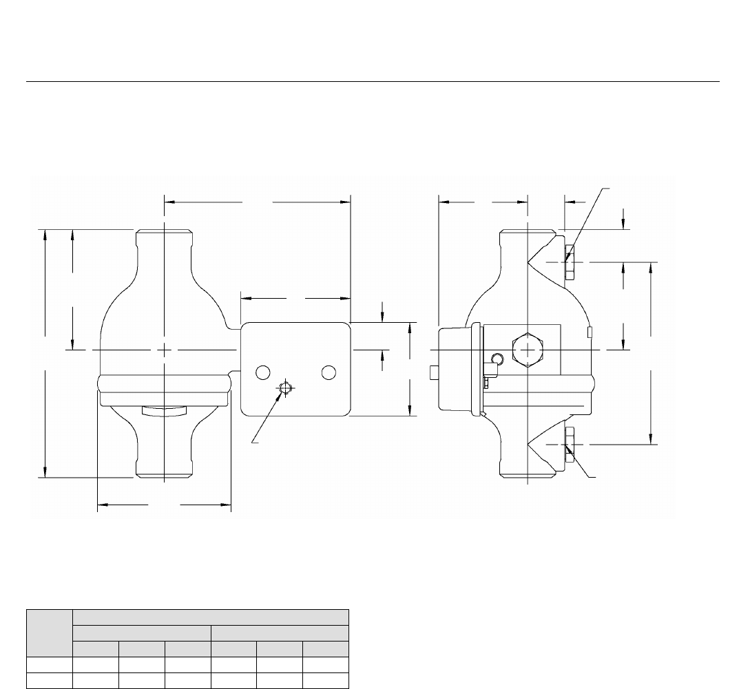
The forged‐in horizontal line on a 2100 or 2100E
displacer cage indicates the approximate switching
point. When mounted, the 2100 or 2100E switch is
positioned so that the horizontal line corresponds to
the level at which switching is desired. Isolating valves
should be installed in the equalizing piping between
the tank and the cage. Dimensions are shown in figure
5 and table 1.
Ordering Information
Application
When ordering, specify:
n Supply pressure (2100 switch only)
n SPDT or DPDT switch construction (2100E switch
only)
n Maximum working pressure and temperature
n Switching action for high or low level alarming
Construction
Refer to the specifications. Review the information
under each specification and in the referenced figures;
specify the desired selection whenever there is a
choice to be made. High level switching and
right‐hand mounting will be supplied automatically
unless otherwise specified. Always specify the
complete type number of the desired equipment.
2100 and 2100E Level Switches
D200032X012
Product Bulletin
32.2:2100
February 2014
6
Figure 5. Dimensions (also see table 1)
GE59300
1 NPT
TAPPED & PLUGGED
38
(1.50)
43
(1.69)
102
(4.00)
211
(8.31)
mm
(INCH)
1 NPT
TAPPED & PLUGGED
1/4 NPT AIR CONNECTION
0N BACK (2100 SWITCH ONLY)
C
216
(8.51)
32
(1.25)
152
(6.00)
287
(11.31
140
(5.50) A
B
Table 1. Dimensions
TYPE
DIMENSIONS
mm Inches
A B C A B C
2100 127 108 103 5.00 4.25 4.06
2100E 130 57 111 5.12 2.25 4.38

2100 and 2100E Level Switches
D200032X012
Product Bulletin
32.2:2100
February 2014
7

2100 and 2100E Level Switches
D200032X012
Product Bulletin
32.2:2100
February 2014
8
Emerson Process Management
Marshalltown, Iowa 50158 USA
Sorocaba, 18087 Brazil
Chatham, Kent ME4 4QZ UK
Dubai, United Arab Emirates
Singapore 128461 Singapore
www.Fisher.com
The contents of this publication are presented for informational purposes only, and while every effort has been made to ensure their accuracy, they are not
to be construed as warranties or guarantees, express or implied, regarding the products or services described herein or their use or applicability. All sales are
governed by our terms and conditions, which are available upon request. We reserve the right to modify or improve the designs or specifications of such
products at any time without notice.
E 1971, 2014 Fisher Controls International LLC. All rights reserved.
Fisher is a mark owned by one of the companies in the Emerson Process Management business unit of Emerson Electric Co. Emerson Process Management,
Emerson, and the Emerson logo are trademarks and service marks of Emerson Electric Co. All other marks are the property of their respective owners.
Neither Emerson, Emerson Process Management, nor any of their affiliated entities assumes responsibility for the selection, use or maintenance
of any product. Responsibility for proper selection, use, and maintenance of any product remains solely with the purchaser and end user.
