Emerson Fisher 2500 Data Sheet D103219X012_Feb15_AQ
2015-03-30
: Emerson Emerson-Fisher-2500-Data-Sheet-681651 emerson-fisher-2500-data-sheet-681651 emerson pdf
Open the PDF directly: View PDF ![]() .
.
Page Count: 16
www.Fisher.com
Fisherr Level Instruments
W8678
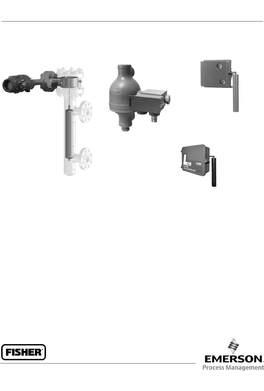
FIELDVUE DLC3010 DIGITAL LEVEL
CONTROLLER IN COMBINATION WITH
A FISHER 249W SENSOR
FISHER 2100E
ELECTRIC LEVEL SWITCH
X0660
FISHER L2e ELECTRIC
LEVEL CONTROLLER
X0682
W8418‐1
FISHER L2 PNEUMATIC
LEVEL CONTROLLER
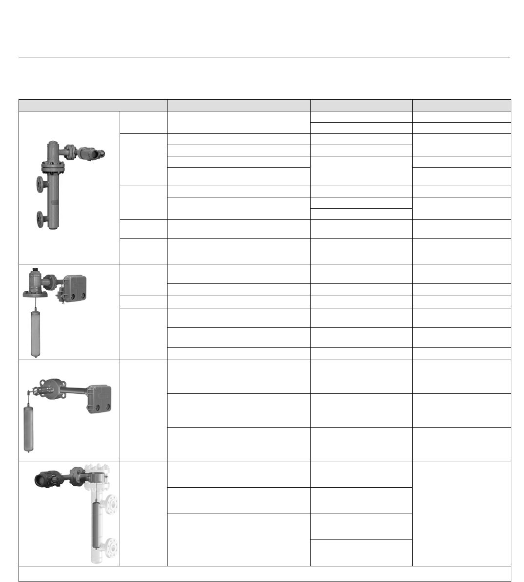
n FIELDVUE™ Digital Level Instruments—
Microprocessor‐based, communicating digital level
transmitter for liquid level, specific gravity (density),
and liquid level interface. Using HARTR or
FOUNDATION™ fieldbus communications protocol,
the DLC3010/DLC3020f digital level controller gives
easy access to information critical to process
operation. Available in combination with a 249
sensor to meet mounting requirements.
n Fisher 2100E electric switch and 2100 on-off
pneumatic switch— Sense high or low liquid levels.
Typically, these switches electrically or
pneumatically operate safety shutdown systems for
field processing equipment in oil and gas industry
applications
n Liquid Level Controllers— Displacer type sensors
used to detect liquid level or interface of two liquids
of different specific gravities. The L2e electric level
controller, in conjunction with the Fisher
easy-Drive™ actuator, can provide a fully electric
level control loop; the L2 pneumatic level controller
offers snap-acting, throttling control, while the
on-off/direct acting L2sj controller features a
low-bleed relay to help to conserve natural gas to
reduce emissions.
n Pneumatic Liquid Level Instruments— Proportional
control mode. The 2500 controller/transmitter
receives the change in fluid level or fluid‐to‐fluid
interface level from the change in buoyant force the
fluid exerts on the sensor displacer. Available in
combination with a 249 sensor to meet mounting
requirements.
Level Instruments
D103219X012
Product Bulletin
11.2:Level
February 2015
Level Instruments
D103219X012
Product Bulletin
11.2:Level
February 2015
2
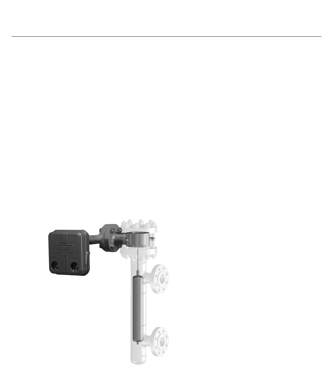
FIELDVUE Digital Level
Instruments
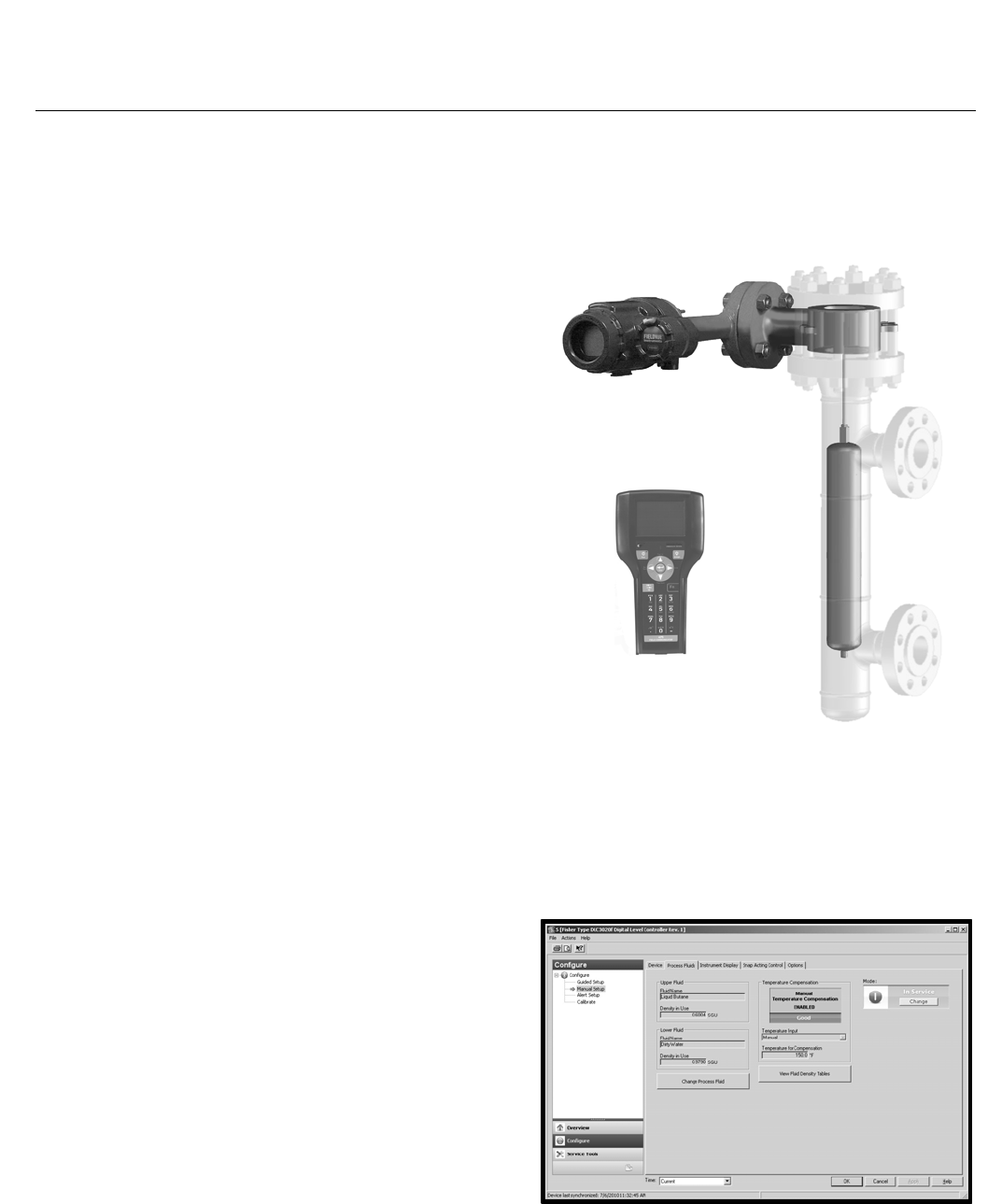
FIELDVUE DLC3010 digital level controllers (figures 1
and 3) are loop‐powered instruments. In conjunction
with a 249 sensor, they measure changes in liquid
level, the level of an interface between two liquids, or
liquid specific gravity (density). The DLC3020f is a
fieldbus‐powered instrument that measures liquid
level or interface between two liquids. A level, density,
or interface level change in the measured fluid causes
a change in the displacer position.
This change is transferred to the torque tube assembly
and to the digital level controller lever assembly. The
rotary motion moves a magnet attached to the lever
assembly, changing the magnetic field that is sensed
by the Hall‐effect sensor. In the DLC3010, the sensor
converts the magnetic field signal to a varying
electronic signal, which is converted to a 4‐20 mA
output signal. In the DLC3020f, the sensor converts
the changing magnetic field to a digital signal, which is
ambient temperature compensated, linearized, and
sent to the electronics assembly.
Standard or Custom Configuration... the DLC3010
digital level controller in combination with a 249W
sensor enables users to install digital level transmitters
to a variety of industry standard or custom process
vessel connections. The sensor consists of a wafer
body, torque tube assembly and displacer and is rated
for CL150, 300, and 600. The wafer body mounts
between NPS 3 or 4 raised face flanges. Custom
configurations are also available to meet your specific
application requirements. Refer to the
DLC3010/DLC3020f specifications in tables 1, 2, 3, and
9, and the 249 specifications in tables 4, 5, 6, 7, 8, and
9 for product line capabilities and options.
HART/AMS Compliant... The DLC3010 uses HART
protocol to interface with the Field Communicator
(see figure 1) for field interface operations. Advanced
user‐interface capabilities are enabled by AMS Suite:
Intelligent Device Manager.
FOUNDATION fieldbus/AMS Compliant... The DLC3020f
uses FOUNDATION fieldbus protocol to interface with the
Field Communicator (see figure 1) for field interface
operations. Advanced user‐interface capabilities are
enabled by AMS Suite: Intelligent Device Manager (see
figure 2).
Figure 1. Fisher DLC3010 Digital Level Controller in
Combination with a 249W Sensor —Installed in a
Typical Customer‐Supplied Cage
W8678
475 FIELD COMMUNICATOR
Figure 2. AMS Suite: Intelligent Device Manager
Configuration Screen
Level Instruments
D103219X012
Product Bulletin
11.2:Level
February 2015
3
Simplified Setup and Calibration... With the electronic
Device Setup, digital level controller startup is
straightforward and fast. Level and temperature
alarms, specific gravity tables, calibration trim, and
trending are readily configurable. DLC3010/DLC3020f
digital level controllers also support re‐ranging
without a fluid reference.
Responsive to Small Process Change... Accurate,
high‐gain analog‐to‐digital conversion enables
measurement of small changes in the process variable.
In addition, an input filter and output damping may be
adjusted by the user to attenuate noise from
mechanical disturbance or liquid turbulence at the
displacer.
Easy Maintenance... Field wiring connections are in a
compartment separated from the electronics. This
helps to protect the electronics from any moisture
brought into the housing by the field wiring. This also
eases installation and maintenance. The digital level
controller does not have to be removed to facilitate
troubleshooting or service. However, if it is necessary
to remove the digital level controller for in‐shop
maintenance and calibration, field wiring does not
need to be disconnected.
Figure 3. FIELDVUE DLC3020f Digital Level Controller
W6102‐1
Note
Mountings for Masoneilan, Yamatake and Foxboro/Eckhardt
sensors are available. Contact your Emerson Process
Management sales office for mounting kit information.
Table 1. FIELDVUE DLC3010 General Specifications
Controller
Selections(1)
For use with 249 caged and
uncaged displacer sensors DLC3010
Input Signal
Level, Interface or Density: Rotary motion of the torque tube shaft proportional to changes in liquid lever,
interface level, or density that change the buoyancy of the displacer.
Process Temperature: Interface for 2‐ or 3‐wire 100 ohm platinum RTD for sensing process temperature,
or optional user‐entered target temperature to permit compensating for changes in specific gravity
Output Signal Analog 4‐20 mA DC direct (increasing input increases output) or reverse action
Digital HART 1200 baud FSK (frequency shift keyed)
Supply 12‐30 VDC; the instrument has reverse‐polarity protection
Ambient Relative Humidity 0 to 95% non‐condensing
Approximate Weight (Controller) 2.7 kg (6 pounds)
Option Heat insulator
Electrical Housing NEMA 4X, CSA Enclosure, IP66
Hazardous Area Classification(2)
CSA—Intrinsically Safe, Explosion-proof, Division 2, Dust Ignition-proof
FM—Intrinsically Safe, Explosion-proof, Non-incendive, Dust Ignition-proof
ATEX—Intrinsically Safe, Type n, Flameproof
IECEx—Intrinsically Safe, Type n, Flameproof
1. Also refer to tables 4, 5, 6, and 7.
2. Other Certifications/Classifications available. Contact your Emerson Process Management Sales office for additional information.
Level Instruments
D103219X012
Product Bulletin
11.2:Level
February 2015
4
Table 2. FIELDVUE DLC3020f General Specifications
Controller
Selections(1)
For use with 249 caged and
uncaged displacer sensors DLC3020f
Device Inputs
Level Sensor Input: Rotary motion of the torque tube shaft proportional to buoyant force of the displacer
caused by changes in liquid level or interface level.
Process Temperature: Interface for 2‐ or 3‐wire 100 ohm platinum RTD for sensing process temperature;
AO Block - Foundation fieldbus temperature transmitter; Manual - compensation values entered manually
in the device
Digital Communication Protocol Foundation fieldbus registered device (ITK 5)
Supply 9 to 32 volts DC, 17.7 mA DC; instrument is not polarity sensitive
Ambient Relative Humidity 0 to 95% non‐condensing
Approximate Weight (Controller) 2.7 kg (6 pounds)
Option Heat insulator
Electrical Housing Type 4X, NEMA 4X, IP66
Hazardous Area Classification(2)
CSA—Intrinsically Safe, Explosion-proof, Division 2, Dust Ignition-proof
FM—Intrinsically Safe, Explosion-proof, Non-incendive, Dust Ignition-proof
ATEX—Intrinsically Safe, Type n, Flameproof
IECEx—Intrinsically Safe, Type n, Flameproof
1. Also refer to tables 4, 5, 6, and 7.
2. Other Certifications/Classifications available. Contact your Emerson Process Management Sales office for additional information.
Table 3. FIELDVUE DLC3010/DLC3020f Performance(1)
Performance Criteria Stand‐Alone DLC3010 w/ NPS 3 249W,
Using a14‐inch Displacer
DLC3010 w/ All Other
249 Sensors
DLC3010 DLC3020f(2)
Independent Linearity $0.25% of output span $0.1% of output span $0.8% of output span $0.5% of output span
Hysteresis < 0.2% of output span < 0.50% of output span - - - - - -
Repeatability $0.1% of full scale output < 0.10% of output span $0.5% of output span $0.3% of output span
Dead Band < 0.05% of input span $ 0.10% (RH9.2% to 90%) - - - - - -
Hysteresis and Dead Band - - - - - - < 1.0% of output span < 1.0% of output span
Accuracy - - - $0.15% - - - - - -
Process Sensor
Range (Input
Signal)
Fluid Level or Fluid
Interface Level
From 0 to 100 percent of displacer length(3)—standard lengths for all sensors are 356 mm (14 inches)
or 813 mm (32 inches); other lengths available depending on sensor construction
Fluid Density
(DLC3010)
From 10 to 100 percent of displacement force change obtained with given displacer volume—standard volumes
are 1016 cm3 (62 in3) for 249C and 249CP sensors and 1622 or 1360 cm3 (99 or 83 in3) for most other sensors;
other volumes available depending upon sensor construction
Allowable
Specific
Gravity
(Standard)
Fluid Level or Fluid
Interface Level Specific gravity range, 0.05 to 1.10; Minimum differential specific gravity 0.05(4)
Fluid Density
(DLC3010) Specific gravity range, 0.1 to 1.10; Minimum change in specific gravity 0.05(4)
Zero
Adjustment
Fluid Level or Fluid
Interface Level
Continuously adjustable to position span of less than 100 percent anywhere within displacer length, and report
the value in engineering units with any desired bias.
Fluid Density
(DLC3010)
Continuously adjustable to position span of less than 90 percent anywhere within 10 to 100 percent of
displacement force change obtained with given displacer volume.
1. At full design span, reference conditions.
2. To lever assembly rotation inputs.
3. The torque tube and the displacer must be properly sized for the application in order for 0 to 100% of displacer length to be available.
4. With a nominal 4.4 degrees torque tube shaft rotation for a 0 to 100 percent change in liquid level (specific gravity=1), the digital level controller can be adjusted to provide full output for an
input range of 5% of nominal input span. This equates to a minimum differential specific gravity of 0.05 with standard volume displacers. Operating at 5% proportional band will degrade
accuracy by a factor of 20. Using a thin wall torque tube, or doubling the displacer volume will each roughly double the effective proportional band. When proportional band of the system
drops below 50%, changing displacer or torque tube should be considered if high accuracy is a requirement.
Level Instruments
D103219X012
Product Bulletin
11.2:Level
February 2015
5
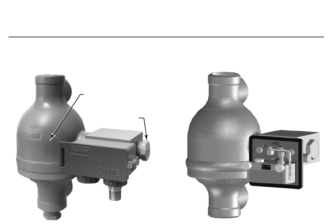
Figure 4. Fisher 2100E Electric Liquid Level Switch
APPROXIMATE
SWITCHING POINT
LOCATION OF
OPTIONAL
SIGHT WINDOW
X0682
Fisher 2100 Liquid Level
Switches
Typically, 2100E and 2100 switches electrically or
pneumatically operate safety shutdown systems for
field processing equipment in oil and gas industry
applications
Switch construction comes in a left‐hand as well as a
right‐hand mounting version. The explosion‐proof,
hermetically sealed 2100E switch is offered as both a
factory mounting and as an electric switch retrofit to
the proven 2100 switch.
With the 2100E switch rising liquid level exerts a
buoyant force on the torque tube that either activates
or deactivates an electrical SPDT or DPDT switch
Figure 5. Fisher 2100 Pneumatic Liquid Level Switch
W9954-1
depending on the switching action desired. Falling
liquid level deactivates or activates the same switch
depending on the action desired.
When the 2100 switch is in the normal position with
the flapper against the nozzle, output pressure cannot
bleed off and remains the same as full supply pressure.
Rising liquid level exerts a buoyant force on the
displacer, producing a torque on the torque tube.
When the torque transmitted by the torque tube
exceeds the torque exerted on the flapper by the
magnet, the flapper snaps away from the nozzle,
allowing output pressure to bleed through the nozzle
faster than supply pressure can enter through the
bleed orifice. The reduced pressure in the output
signal line activates the shutdown or alarm system.
When the liquid level lowers, the falling displacer
forces the flapper into the field of the magnet, letting
the magnet snap the flapper against the nozzle and
causing output pressure to build to full supply
pressure.
Level Instruments
D103219X012
Product Bulletin
11.2:Level
February 2015
6
Fisher L2, L2e, and L2sj
Liquid Level Controllers
Rugged L2, L2e, and L2sj liquid level controllers use a
displacer type sensor to detect liquid level or the
interface of two liquids of different specific gravities.
The reliability of the design make these controllers well
suited for high pressure liquid level applications in
natural gas production, compression, and processing
industries.
The L2 and L2sj devices deliver a pneumatic output
signal to a control valve.
The L2e device uses a single pole double throw (SPDT)
dry contact electric switch to provide differential gap
(DG) control or liquid monitoring. It can be used to
provide an electric control signal to an electrically
actuated control valve.
The sensor uses a threaded 2 NPT connection to the
vessel. Standard constructions use materials that
comply with the requirements of NACE MR0175‐2002.
L2, L2e, and L2sj controllers, in combination with the
sensor, work on the principle that a body immersed in
liquid will be buoyed up by a force equal to the weight
of the liquid displaced. The buoyant force and
resultant movement of the displacer in the liquid is
transmitted to the controller which delivers the signal
to a control valve.
L2 Liquid Level Controllers
Snap‐Acting or Throttling Control... One standard
controller available as either throttling or snap‐acting.
Field‐Reversible Output... The controller can be
adjusted in the field for direct or reverse action without
additional parts. The controller also has adjustable
gain sensitivity.
Easy Maintenance... Both the controller and the sensor
can be easily disassembled to inspect the process seals
and for maintenance.
Figure 6. Fisher L2 Liquid Level Controller
W8418‐1
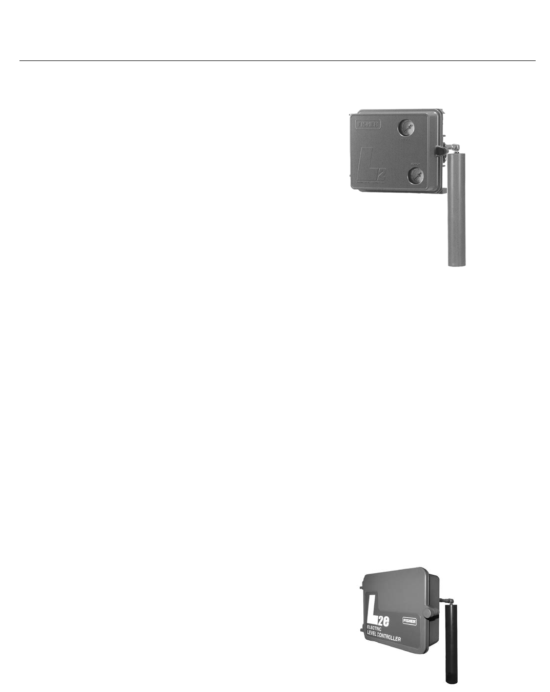
L2e Electric Level Controllers
Effective Level Loop Tuning… Intuitive Zero and Span
adjustments allow flexibility in setting loop
performance over a level range of 5.0 to 559 mm
(0.2 to 22 inches).
More Reliable Control… Premium quality
hermetically-sealed switch with gold contacts and
advanced knife-edge sensing provide highly
dependable and accurate liquid level control.
Environmentally Responsible… Replacing a
conventional pneumatic level loop with fully electric
level control eliminates controller and dump valve
venting and requires less maintenance.
Figure 7. Fisher L2e Liquid Level Controller
X0660
Level Instruments
D103219X012
Product Bulletin
11.2:Level
February 2015
7
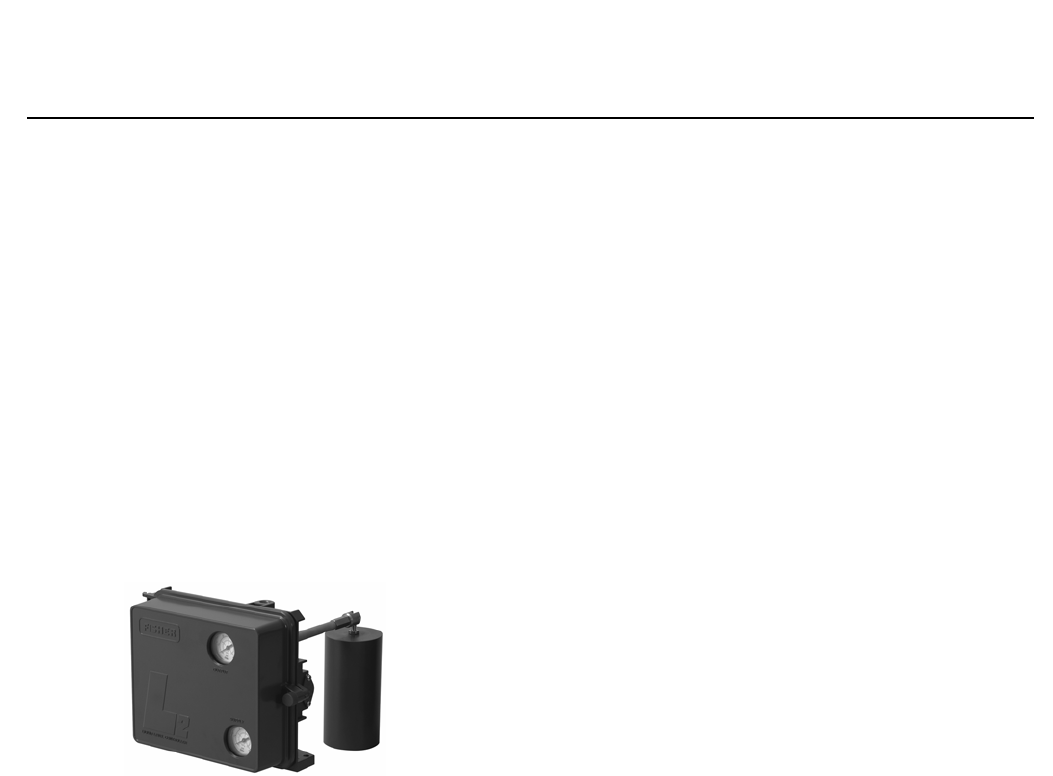
L2sj Liquid Level Controllers
Designed for use with Natural Gas... The L2sj controller
is intended for use with natural gas as the pneumatic
supply.
Reduced Carbon Footprint... Low‐bleed relay helps to
conserve natural gas to reduce greenhouse gas
emissions.
Reduced Operating Costs, Increased Revenue...
Integral action relay with rugged metal seats requires
less maintenance and provides more dependable
liquid level control, which can improve uptime.
Reduced emissions result in an increase in natural gas
available to the sales line.
Figure 8. Fisher L2sj Liquid Level Controller
W9331
Fisher 249 Sensors
249 sensors, in conjunction with either DLC3010/
DLC3020f digital level controllers or 2500 controllers
and transmitters, are designed to measure changes in
liquid level, liquid interface level, or density/specific
gravity inside a process vessel.
249 level sensors are available in both caged and
cageless configurations, as shown in the table below.
Caged sensors provide more stable operation than do
cageless sensors for vessels with internal obstructions
or considerable internal turbulence. Cageless sensors
are generally used on applications requiring large
displacers that are accommodated by large flange
connections. Different displacer stem lengths permit
lowering the displacer to the desired depth.
Refer to table 4, 5, 6, 7, 8, and 9 for product line
capabilities and options.
Level Instruments
D103219X012
Product Bulletin
11.2:Level
February 2015
8
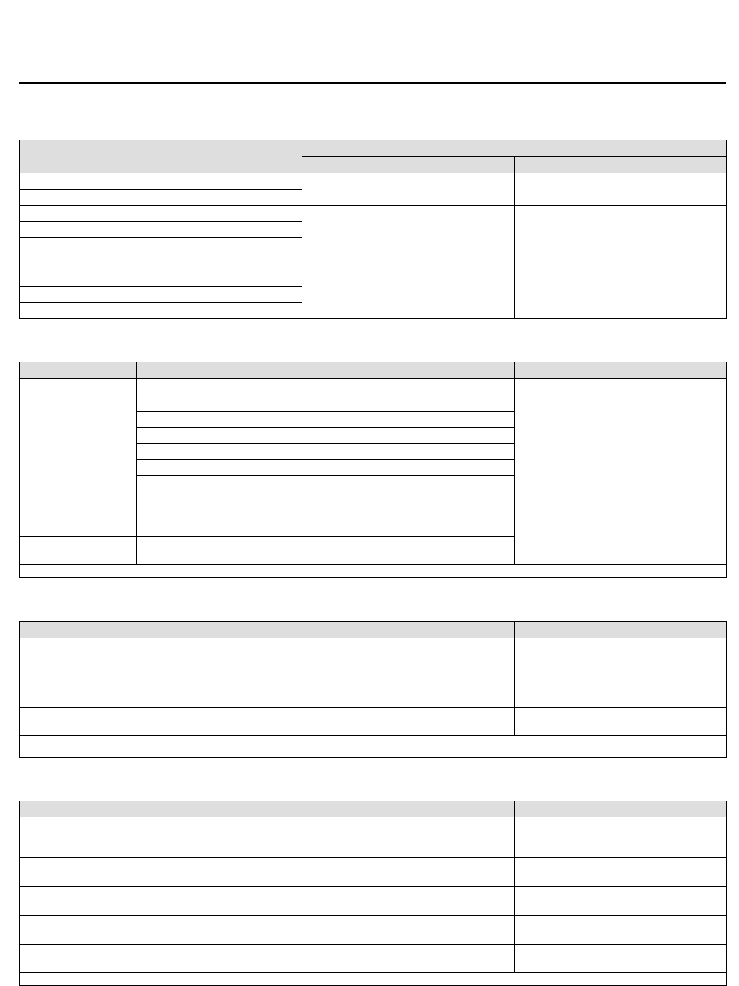
Table 4. Fisher 249 Sensor Displacer Diameters, Sensor Connections, and Ratings
Sensor Type Number(1) Pressure Rating Connection Size Connection Type
Caged
Displacers(2)
W8171
249 CL125 or 250 NPS 1‐1/2 or 2 Screwed or flanged
NPS 2 Flanged
249B
249BF
PN 10/40 or 63/100 DN 40 Flanged
PN 10/16, 25/40, or 63 DN 50
CL600
NPS 1‐1/2 or 2
NPT or socket‐welding ends
CL150, 300, or 600 Raised‐face flanged or
ring‐type joint flanged
249C
CL600 NPS 1‐1/2 or 2 Screwed
CL150, 300, or 600 NPS 1‐1/2 Raised‐face
NPS 2
249K CL1500 NPS 1‐1/2 or 2 Raised‐face flanged or
ring‐type joint flanged
249L CL2500 NPS 2 (if a top connection
is specified, it will be NPS 1
flanged)
Ring‐type joint flanged
Top‐Mounted Cageless
Sensors(2)
W8334‐1
249BP CL150, 300, or 600 NPS 4 Raised‐face flanged or
ring‐type joint flanged
CL150 or 300 NPS 6 or 8 Raised‐face flanged
249CP CL150, 300, or 600 NPS 3 Raised‐face flanged
249P
PN 10/16, 25/40, or 63
(Ratings to PN 250 also available) DN 100 Flanged
CL900 or 1500 NPS 4 Raised‐face flanged or
ring‐type joint flanged
CL150 through 2500 NPS 6 or 8 Raised‐face flanged
Side‐Mounted
Cageless Sensors(2)
W9354
249VS
PN 10 to PN 160 NPS 4 Raised‐face or flat‐face
CL125, 150, 250, 300, 900, or 1500 NPS 4 Raised‐face or flat‐face
CL600, 900, or 2500 NPS 4 Butt weld end
Customer‐Supplied
Cage(2)
W8678
249W
PN 10/16, 25/40 Type B flange DN 80
Raised‐face flanged
PN 25/40 Type B flange DN 100
CL150, 300, 600
NPS 3
NPS 4
1. Not all sensor types are available in all world areas. Contact your Emerson Process Management sales office for information on sensor availability.
2. 249 sensors may be mounted on either DLC3010/DLC3020f instruments, or 2500 controllers/transmitters.
Level Instruments
D103219X012
Product Bulletin
11.2:Level
February 2015
9
Table 5. Fisher 249 Sensors Displacer Lengths
Sensor Type Number Standard Displacer Length
mm Inches
Caged Displacers 356 or 813 14 or 32
249
249B, 249C, 249BF, 249K, 249L
356, 813, 1219, 1524, 1829,
2134, 2438, 2743, 3048
14, 32, 48, 60, 72, 84,
96, 108, 120
Top‐Mounted Cageless Sensors
249BP, 249CP, 249P
Side‐Mounted Cageless Sensors
249VS
Top‐Mounted or on Customer Supplied Cage
249W
Table 6. Fisher 249 Sensor Construction Materials
Part Type Number Material Notes
Cage, head,
torque tube arm
249 Cast iron
For optional materials, and parts not shown,
contact your Emerson Process Management
sales office.
249B, 249BF, and 249BP Carbon steel
249C and 249CP CF8M (316 stainless steel)
249K Steel standard
249L Steel standard
249P Carbon Steel
249VS LCC (steel), WCC (steel), CF8M
Wafer body,
torque tube arm
249W NPS 3
NPS 4
WCC, CF8M
LCC, CF8M
Standard Trim(1) All S31600
Bolting All Steel grade B7 studs or cap screws
and grade 2H nuts (standard),
1. Trim parts include displacer rod, driver bearing; displacer stem parts, and stem connection parts.
Table 7. Fisher 249 Displacer and Torque Tube Materials
Part Standard Material Other Materials
Displacer 304 Stainless Steel
316 Stainless Steel for 249C, 249CP
316 Stainless Steel, N10276, N04400,
Plastic, and Special Alloys
Displacer Stem,
Driver Bearing,
Displacer Rod and Driver
316 Stainless Steel N10276, N04400, other Austenitic Stainless
Steels, and Special Alloys
Torque Tube N05500(1)
316 SST for 249C, 249CP 316 Stainless Steels, N06600, N10276
1. N05500 is not recommended for spring applications above 232_C (450_F). Contact your Emerson Process Management sales office or application engineer if temperatures exceeding this
limit are required.
Table 8. Maximum Unbuoyed Displacer Weight
Sensor Type Torque Tube Wall Thickness Displacer Weight WT (lb)
249, 249B, 249BF, 249BP, 249W
Thin
Standard
Heavy
3.3
5.0
9.5
249C, 249CP Standard
Heavy
4.0
6.4
249VS Thin
Standard
3.0
5.5
249L, 249P(1) Thin
Standard
4.5
8.5
249K Thin
Standard
3.8
7.3
1. High pressure CL900 through 2500.
Level Instruments
D103219X012
Product Bulletin
11.2:Level
February 2015
10
Table 9. Temperatures
Temperature Type or Material Temperature Capability Notes
_C_F
Ambient
DLC3010 / DLC3020f –40 to 80 –40 to 176
For process temperatures
below -29_C (-20_F) and for
guidance on the need for a
heat insulator, contact your
Emerson Process
Management sales office. If
the ambient dew point is
higher than the process
temperature, ice might
form and cause instrument
malfunction and reduce
insulator effectiveness.
Standard 2500 -40 to 71 -40 to 160
High‐temperature 2500 -18 to 104 0 to 220
Process
Cast iron sensor parts –29 to 232 –20 to 450
Steel sensor parts –29 to 427 –20 to 800
Stainless steel sensor parts –198 to 427 –325 to 800
N04400 –198 to 427 –325 to 800
Graphite/stainless steel
gaskets –198 to 427 –325 to 800
N04400/PTFE gaskets –73 to 204 –100 to 400
Combination of ambient
and process
Some combinations of process and ambient temperatures within the above ranges require
an optional heat insulator to protect the instrument from high or low temperatures. For
example, an ambient temperature of 30_C or 86_F and a process temperature of 200_C or
392_F require a heat insulator.
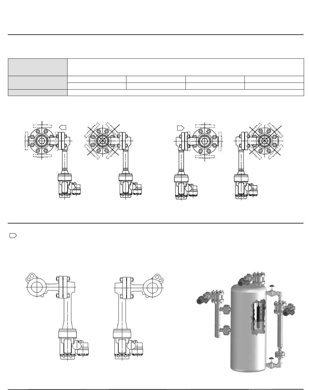
Connection Styles and
Positions
Figure 9. Cage Connection Styles (also see table 10)
STYLE 2 STYLE 3 STYLE 4
28B5536‐1
B1820‐2
Note:
Cage connections shown illustrate the DLC3010/DLC3020f. Cage connections are also applicable to 2500 controllers/transmitters.
STYLE 1
Level Instruments
D103219X012
Product Bulletin
11.2:Level
February 2015
11
Table 10. Cage Connection Styles (also see figure 9)
Connection Types:
S = Screwed
F = Flanged
SW = Socket welding
Connection Locations:Style 1 Style 2 Style 3 Style 4
Top and bottom Top and lower side Upper side and lower side Upper side and bottom
Example: F‐1 means flanged connections at the top and bottom of the cage.
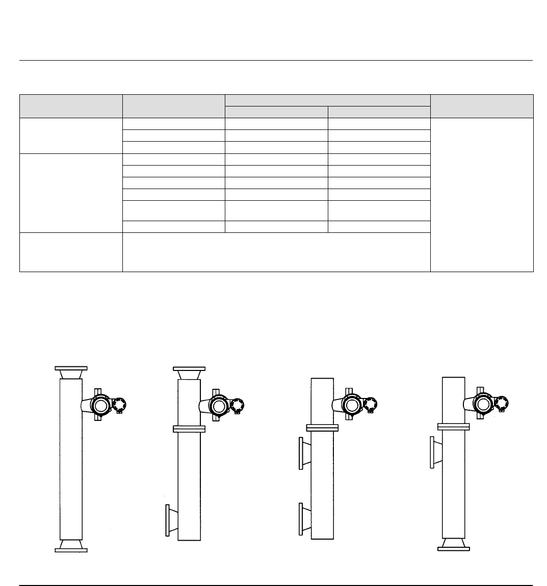
Figure 10. Mounting Positions—Caged Displacers
8
24
6
3
7
1
51
18
2
4
6
1
3
7
5
RIGHT‐HAND MOUNTING LEFT‐HAND MOUNTING
Note:
Mounting positions shown illustrate the DLC3010/DLC3020f. Mounting positions are also applicable to 2500 controllers/transmitters.
1 Position 5 is not available for NPS 2 CL300 and 600 249C.
Figure 11. Mounting Positions—Wafer Style (Customer Supplied Cage)
CAGE WITH SIDE
CONNECTIONS
TOP‐MOUNTED
ON VESSEL
CAGE WITH TOP AND
BOTTOM CONNECTIONS
RIGHT‐HAND MOUNTING LEFT‐HAND MOUNTING
Note:
Mounting positions shown illustrate the DLC3010/DLC3020f. These positions are also applicable to 2500 controllers/transmitters.
Level Instruments
D103219X012
Product Bulletin
11.2:Level
February 2015
12
Pneumatic Liquid Level
Instruments
Fisher 2500 controllers and transmitters (figures 12
and 13) are rugged, dependable, and simply
constructed pneumatic instruments. In conjunction
with a 249 sensor, they sense liquid level or interface
level in a vessel, and produce a standard pneumatic
output signal proportional to the process variable.
Standard or Custom Configuration... The 2500
controller in combination with a 249W sensor enables
users to install pneumatic level controllers to a variety
of industry standard or custom process vessel
connections. The sensor consists of a wafer body,
torque tube assembly and displacer and is rated for
CL150, 300, and 600. The wafer body mounts between
NPS 3 or 4 raised face flanges. Custom configurations
are also available to meet your specific application
requirements. Refer to the 2500 specifications in
tables 9, 11, 12, and 13, and the 249 specifications in
tables 4, 5, 6, 7, 8, and 9.
Easy Adjustment... Simple dial‐knobs make set point
and proportional valve opening changes
straightforward and easy.
Simple, Durable Construction... Few moving parts are
used. Knife‐edged driver bearing in sensor, and plated
brass instrument case ball bearing for torque tube
rotary shaft help provide low friction operation.
Reduced Maintenance and Operating Costs...
Spring‐out wire provides for in‐service cleaning of relay
orifice. Supply pressure conservation is enhanced
because relay exhaust opens only when output
pressure is being reduced.
Figure 12. Fisher 2500 Controller in Combination with a 249W Sensor— Installed in a Typical
Customer‐Supplied Cage
W8679
Level Instruments
D103219X012
Product Bulletin
11.2:Level
February 2015
13
Table 11. Fisher 2500 Controller/Transmitter General Specifications
Controller and Transmitter
Selections(1)
2500 Proportional pneumatic controller
2502 Proportional‐plus‐reset pneumatic controller
2502F Proportional‐plus reset pneumatic controller with anti‐reset windup
2500T Proportional pneumatic transmitter
2500S Differential gap (on‐off) pneumatic controller with full adjustment
2503 Differential gap (on‐off) pneumatic controller with limited adjustment
Process Sensor Range (Input Signal)
Fluid level or fluid
interface level
From 0 to 100 percent of displacer length(2)—standard lengths for all
sensors are 356 mm (14 inches) or 813 mm (32 inches); other lengths
available depending on sensor construction
Fluid density
From 0 to 100 percent of displacement force change obtained with
given displacer volume—standard volumes are 1016 cm3 (62 in3) for
249C and 249CP sensors and 1622 or 1360 cm3 (99 or 83 in3) for
most other sensors; other volumes available depending upon sensor
construction
Allowable Specific Gravity (Standard)
Fluid level or fluid
interface level
2503 and 2503R: Specific gravity range, 0.25 to 1.10
All other types: Specific gravity range, 0.20 to 1.10
Fluid density 2503 and 2503R: Minimum change in specific gravity, 0.25
All other types: Minimum change in specific gravity, 0.20
Set Point Adjustment (Controllers only)
Continuously adjustable to position control point or differential gap
of less than 100 percent anywhere within displacer length (fluid or
interface level) or displacement force change (density)
Zero Adjustment (Transmitters only)
Continuously adjustable to position span of less than 100 percent
anywhere within displacer length (fluid or interface level) or
displacement force change (density)
Reset Adjustment (Proportional‐Plus‐Reset Controllers Only) Continuously adjustable from 0.005 to over 0.9 minutes per repeat
(from 200 to under 1.1 repeats per minute)
Anti‐Reset Differential Relief (2502F and 2502FR Controllers Only)
Continuously adjustable from 0.14 to 0.48 bar (2 to 7 psi)
differential to relieve excessive difference between proportional
and reset pressures
Output Signal‐‐Direct (Increasing Level Increases
Output) or Reverse Action
Proportional or reset
controllers and
transmitters
0.2 to 1.0 or 0.4 to 2.0 bar (3 to 15 or 6 to 30 psig)
Differential gap
controllers with full
adjustment
0 and 1.4 or 0 and 2.4 bar (0 and 20 or 0 and 35 psig)
Differential gap
controllers with limited
adjustment
0 and full supply pressure
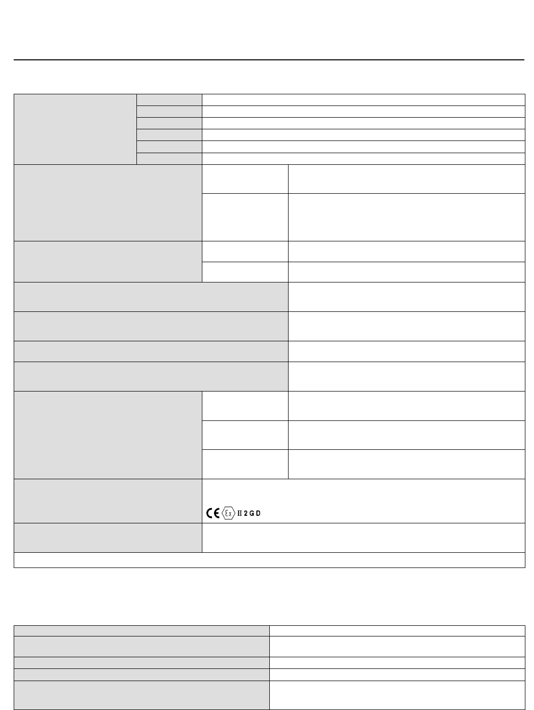
Hazardous Area Classification
2500 controllers/transmitters comply with the requirements of
ATEX Group II Category 2 Gas and Dust
Options
Stainless steel heat insulator assembly
Liquid level sight gauges
Mechanical level indicator
1. Also refer to tables 4, 5, 6, and 7.
2. The torque tube and the displacer must be properly sized for the application in order for 0 to 100% of displacer length to be available.
Table 12. Fisher 2500 Controller/Transmitter Performance
Independent Linearity (Transmitters Only) 1 percent of output pressure change at span of 100 percent
Hysteresis 0.6 percent of output pressure change at 100 percent of proportional band,
differential gap, or span
Repeatability 0.2 percent of displacer length or displacement force change
Deadband (Except Differential Gap Controllers) 0.05 percent of proportional band or span
Typical Frequency Response
4 Hz and 90‐degree phase shift at 100 percent of proportional band,
diferential gap, or span with output pipe to typical instrument bellows using
6.1 meters (20 feet) of 6.3 mm (1/4‐inch) tubing
Level Instruments
D103219X012
Product Bulletin
11.2:Level
February 2015
14
Table 13. Fisher 2500 Controller/Transmitter Supply Pressure
Output Signal
Standard Supply and
Output Pressure Gauge
Indications(1)
Normal Operating
Supply Pressure(2)
Air Consumption at Normal Operating
Supply Pressure(3)
Normal m3/h(4) Scfh(4)
Bar Psig Min(5) Max(6) Min(5) Max(6)
0.2 to 1.0 bar (3 to 15 psig),
except 0 and 1.4 bar (0 and 20
psig)(2) for on‐off controllers
0 to 30 psig 1.4 20 0.11 0.72 4.2 27
0.4 to 2.0 bar (6 to 30 psig),
except 0 and 2.4 bar (0 and 35
psig)(2) for on‐off controllers
0 to 60 psig 2.4 35 0.19 1.1 7 42
1. Consult your Emerson Process Management sales office about gauges in other units.
2. Control and stability may be impaired if this pressure is exceeded (except 2503 or 2503R controller without proportional valve).
3. Except 2503 or 2503R controller, which bleeds only when relay is open at exhaust position.
4. Normal m3/hr=normal cubic meters per hour at 0_C and 1.01325 bar. Scfh=standard cubic foot per hour at 60_F and 14.7 psia.
5. At zero or maximum proportional band or span setting.
6. At setting in middle of proportional band or span range.
Figure 13. Typical Controller
W0656‐1
W8333

Level Instruments
D103219X012
Product Bulletin
11.2:Level
February 2015
15
Related Documents
Other documents containing information related to
level instruments include:
n FIELDVUE DLC3010 Digital Level Controller
(Bulletin 11.2:DLC3010) (D102727X012)
n FIELDVUE DLC3020f Digital Level Controller
(Bulletin 11.2:DLC3020f) (D103433X012)
n Fisher 2100 Pneumatic and 2100E Electric Liquid
Level Switches (Bulletin 32.2:2100) (D200032X012)
n Fisher L2 Liquid Level Controller
(Bulletin 34.2:L2) (D103034X012)
n Fisher L2e Electric Level Controller
(Bulletin 34.2:L2e) (D103532X012)
n Fisher L2sj Liquid Level Controller
(Bulletin 34.2:L2sj) (D103229X012)
n Fisher 2500‐249 Pneumatic Controllers and
Transmitters (Bulletin 34.2:2500) (D200037X012)
n Fisher 249 Sensor, Level Controller, and Transmitter
Dimensions (Bulletin 34.2:249) (D200039X012)
These documents are available from your Emerson
Process Management sales office. Also visit our
website at www.Fisher.com.

Level Instruments
D103219X012
Product Bulletin
11.2:Level
February 2015
16
Emerson Process Management
Marshalltown, Iowa 50158 USA
Sorocaba, 18087 Brazil
Chatham, Kent ME4 4QZ UK
Dubai, United Arab Emirates
Singapore 128461 Singapore
www.Fisher.com
The contents of this publication are presented for informational purposes only, and while every effort has been made to ensure their accuracy, they are not
to be construed as warranties or guarantees, express or implied, regarding the products or services described herein or their use or applicability. All sales are
governed by our terms and conditions, which are available upon request. We reserve the right to modify or improve the designs or specifications of such
products at any time without notice.
E 2005, 2015 Fisher Controls International LLC. All rights reserved.
Fisher, FIELDVUE, and easy-Drive are marks owned by one of the companies in the Emerson Process Management business unit of Emerson Electric Co.
Emerson Process Management, Emerson, and the Emerson logo are trademarks and service marks of Emerson Electric Co. All other marks are the property
of their respective owners.
Neither Emerson, Emerson Process Management, nor any of their affiliated entities assumes responsibility for the selection, use or maintenance
of any product. Responsibility for proper selection, use, and maintenance of any product remains solely with the purchaser and end user.
