Emerson Fisher 3582 Data Sheet D200062X012_Feb15_AQ
2015-03-30
: Emerson Emerson-Fisher-3582-Data-Sheet-681660 emerson-fisher-3582-data-sheet-681660 emerson pdf
Open the PDF directly: View PDF ![]() .
.
Page Count: 12
www.Fisher.com
Fisherr 3582 and 3582i Positioners and 582i
Electro-Pneumatic Converter
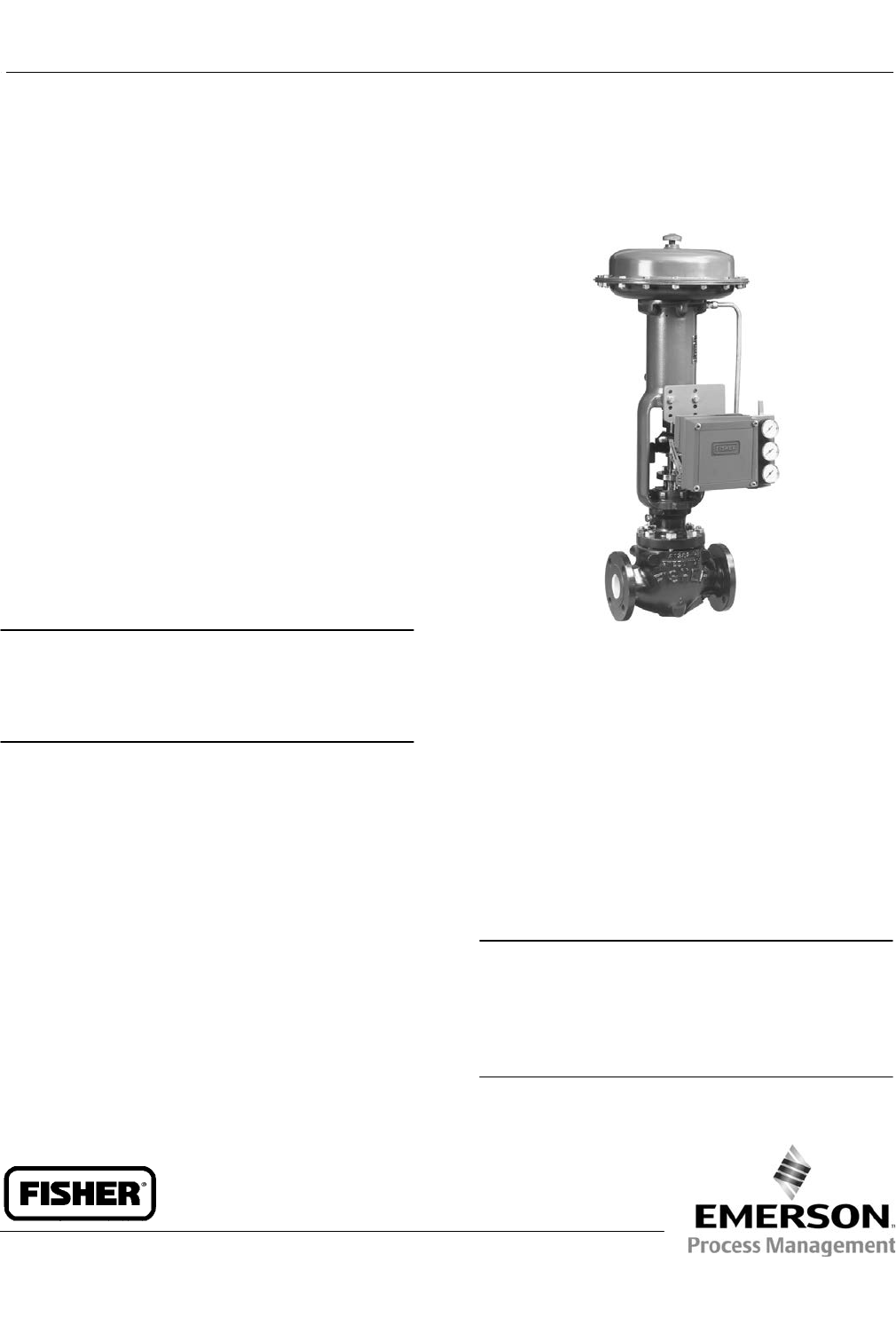
Fisher 3582 pneumatic valve positioners and 3582i
electro-pneumatic valve positioners, shown in figure 1,
are used with diaphragm-actuated, sliding-stem
control valve assemblies. The pneumatic valve
positioners receive a pneumatic input signal from a
control device and modulate the supply pressure to
the control valve actuator, providing an accurate valve
stem position that is proportional to the pneumatic
input signal.
3582NS positioners are designed for nuclear power
applications. The 3582NS construction includes
materials that provide superior performance at
elevated temperature and radiation levels. The O-rings
are EPDM (ethylene propylene) and the diaphragms
are EPDM/meta-aramid. EPDM demonstrates superior
temperature capability and shelf life over nitrile.
Note
Use a clean, dry, oil-free air supply with instruments
containing EPDM components. EPDM is subject to
degradation when exposed to petroleum-based lubricants.
The meta-aramid diaphragm fabric demonstrates
improved strength retention at elevated temperature
and radiation conditions.
Under the 10CFR50, Appendix B, quality assurance
program, the 3582NS positioner is qualified
commercial grade dedicated. These can be supplied as
10CFR, Part 21 items.
The 3582i electro-pneumatic valve positioner consists
of a Fisher 582i electro-pneumatic converter installed
on a 3582 pneumatic valve positioner. The 3582i
provides an accurate valve stem position that is
proportional to a DC current input signal.
W5498-1
FISHER 3582 PNEUMATIC
VALVE POSITIONER
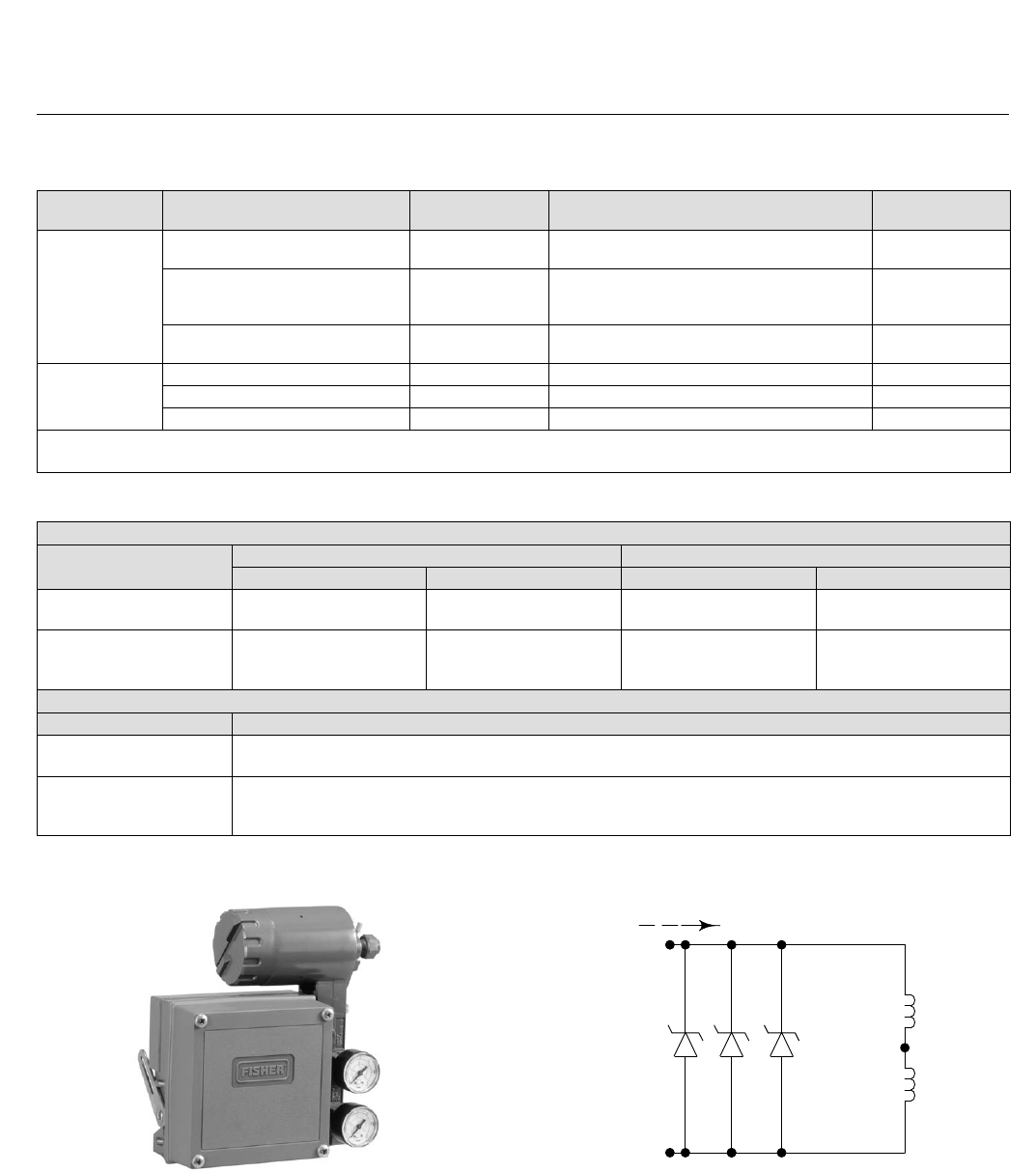
The 582i electro-pneumatic converter, shown in figure
3, is a modular unit that can be installed at the factory
or in the field.
The converter receives a DC current input signal and
provides a proportional pneumatic output signal
through a nozzle/flapper arrangement. The pneumatic
output signal provides the input signal to the
pneumatic positioner, eliminating the need for a
remote mounted transducer.
Note
Upgrading an existing 3582 positioner by field installation of
a 582i electro-pneumatic converter may require changing
the existing positioner mounting and the input signal range.
Contact your Emerson Process Management sales office
when planning an upgrade.
3582 and 3582i Positioners
D200062X012
Product Bulletin
62.1:3582
February 2015

3582 and 3582i Positioners
D200062X012
Product Bulletin
62.1:3582
February 2015
2
Specifications
Note: Specifications for 3582 positioners include
3582A, 3582C, 3582D, 3582G, and 3582NS unless
otherwise indicated
Available Configurations
Refer to Type Number Description
Input Signal
3582
J0.2 to 1.0 bar (3 to 15 psig), J0.4 to 2.0 bar
(6 to 30 psig), or Jsplit range, see table 2.
3582i
4-20 mA DC constant current with 30 VDC maximum
compliance voltage, can be split range, see table 2.
Equivalent Circuit for 3582i
120 ohms shunted by three 5.6-volt zener diodes, see
figure 2
Output Signal
Type: Pneumatic pressure as required by actuator up
to 95 percent of maximum supply
Action: Field-reversible between Jdirect and
Jreverse within the pneumatic valve positioner
Supply Pressure(1)
Recommended: 0.3 bar (5 psi) above actuator
requirement
Maximum: 3.4 bar (50 psig) or pressure rating of
actuator, whichever is lower
Supply Medium
Air or Natural Gas(2)
The 3582i positioner is not approved for use with
Natural Gas as the supply medium
Maximum Input Bellows Pressure Rating(1)
2.4 bar (35 psig)
Maximum Steady-State Air Consumption(3)
3582:
1.4 bar (20 psig) Supply: 0.38 normal m3/hr
(14.0 scfh)
2.0 bar (30 psig) Supply: 0.48 normal m3/hr
(18.0 scfh)
2.4 bar (35 psig) Supply: 0.54 normal m3/hr
(20.0 scfh)
3582i:
1.4 bar (20 psig) Supply: 0.46 normal m3/hr
(17.2 scfh)
2.0 bar (30 psig) Supply: 0.57 normal m3/hr
(21.4 scfh)
2.4 bar (35 psig) Supply: 0.64 normal m3/hr
(23.8 scfh)
Maximum Supply Air Demand(3)
1.4 bar (20 psig) Supply: 4.4 normal m3/hr
(164.5 scfh)
2.0 bar (30 psig) Supply: 6.7 normal m3/hr
(248.5 scfh)
2.4 bar (35 psig) Supply: 7.7 normal m3/hr
(285.5 scfh)
Performance
3582
Independent Linearity: ±1 percent of output signal span
Hysteresis: 0.5 percent of span
3582i
Independent Linearity: ±2 percent of output signal span
Hysteresis: 0.6 percent of span
Electromagnetic Compliance for 582i
electro-magnetic converter
Meets EN 61326-1 (First Edition)
Immunity—Industrial locations per Table 2 of
the EN 61326-1 standard. Performance is
shown in table 1 below.
Emissions—Class A
ISM equipment rating: Group 1, Class A
Note: Electromagnetic Compatibility also applies to
the 3582i positioner.
3582 and 3582i.
Open Loop Gain (Output Signal):
J100 in the range of 0.2 to 1.0 bar (3 to 15 psig)
J55 in the range of 0.4 to 2.0 bar (6 to 30 psig)
Operating Influences
Supply Pressure, For 3582: Valve travel changes less
than 1.67 percent per bar (0.25 percent per 2 psi)
change in supply pressure
Supply Pressure, For 3582i: Valve travel changes less
than 3.62 percent per bar (1.5 percent per 2 psi)
change in supply pressure
- continued -
3582 and 3582i Positioners
D200062X012
Product Bulletin
62.1:3582
February 2015
3
Specifications (Continued)
Operative Temperature Limits(1)
Standard Construction
3582 and 3582i: -40 to 71_C (-40 to 160_F)
3582NS: -40 to 82_C (-40 to 180_F) with EPDM
elastomers
High-Temperature Construction(4)
3582A and C Only: -18 to 104_C (0 to 220_F) without
gauges
Electrical Classification for 582i
CSA— Intrinsically Safe, Explosion-proof, Type n,
Dust-Ignition proof, Division 2,
FM—Intrinsically Safe, Explosion-proof, Type n,
Non-incendive, Dust-Ignition proof,
ATEX—Intrinsically Safe, Type n, Flameproof
IECEx—Intrinsically Safe, Type n, Flameproof (Gas
Atmospheres Only)
Refer to tables 5, 6, 7, and 8 for additional
information
Note: These classifications also apply to the 3582i
positioner
Housing Classification for 582i
CSA—Type 3 Encl.
FM—NEMA 3, IP54
ATEX—IP64
IECEx—IP54
Mount instrument with vent on the side or the
bottom if weatherproofing is a concern.
Note: These classifications also apply to the 3582i
positioner
Other Classifications/Certifications for 582i
CUTR— Customs Union Technical Regulations (Russia,
Kazakhstan, and Belarus)
INMETRO— National Institute of Metrology, Quality,
and Technology (Brazil)
KGS— Korea Gas Safety Corporation (South Korea)
NEPSI— National Supervision and Inspection Centre
for Explosion Protection and Safety of
Instrumentation (China)
Contact your Emerson Process Management sales
office for classification/certification specific
information
Note: These classifications also apply to the 3582i
positioner
Hazardous Area Classifications for 3582
3582 valve positioners comply with the requirements
of ATEX Group II Category 2 Gas and Dust
Meets Customs Union technical regulation TP TC
012/2011 for Groups II/III Category 2 equipment
II Gb c T*X
III Db c T*X
Note: These ratings do not apply to the 3582i
positioner
Construction Materials
Refer to table 3
Pressure Gauges
40 mm (1.5 inch) diameter with plastic case and brass
connection
Jtriple scale (PSI, MPa, and bar) or
Jdual scale (PSI and kg/cm2)
Pressure Connections
1/4 NPT internal
Electrical Connection for 3582i
1/2-14 NPT conduit connection
Maximum Valve Stem Travel
105 mm (4.125 inches); adjustable to obtain lesser
travel with standard input signal
Characterized Cams
See characterized cams section
Approximate Weight
3582: 2.5 kg (5-1/2 pounds)
3582i: 3.6 kg (8 pounds)
Options
JInstrument, output, and supply pressure gauges;
automotive tire valves; or pipe plugs (see Type
Number Description section) JBypass valve (only for
direct-acting, 3582 positioners using a full input
signal range) JCharacterized cams B and C
JConnectors for diagnostic testing JHigh vibration
NOTE: Specialized instrument terms are defined in ANSI/ISA Standard 51.1 - Process Instrument Terminology.
1. The pressure and temperature limits in this document and any applicable standard or code limitation should not be exceeded.
2. Natural gas should contain no more than 20 ppm of H2S.
3. Normal m3/hr--normal cubic meters per hour (0_C and 1.01325 bar absolute); Scfh--standard cubic feet per hour (60_F and 14.7 psia).
4. Not available with bypass or pressure gauges.
3582 and 3582i Positioners
D200062X012
Product Bulletin
62.1:3582
February 2015
4
Table 1. Fisher 582i Electro-Pneumatic Converter(1) EMC Summary Results—Immunity
Port Phenomenon Basic Standard Test Level Performance
Criteria(2)
Enclosure
Electrostatic Discharge (ESD) IEC 61000-4-2 4 kV contact
8 kV air A
Radiated EM field IEC 61000-4-3
80 to 1000 MHz @ 10V/m with 1 kHz AM at 80%
1400 to 2000 MHz @ 3V/m with 1 kHz AM at 80%
2000 to 2700 MHz @ 1V/m with 1 kHz AM at 80%
A
Rated power frequency magnetic
field IEC 61000-4-8 60 A/m at 50 Hz A
I/O signal/control
Burst (fast transients) IEC 61000-4-4 1 kV A
Surge IEC 61000-4-5 1 kV (line to ground only, each) B
Conducted RF IEC 61000-4-6 150 kHz to 80 MHz at 3 Vrms A
Specification limit = ±1% of span
1. The information contained in the table also applies to the 3582i positioner.
2. A = No degradation during testing. B = Temporary degradation during testing, but is self-recovering.
Table 2. Split-Range Capabilities
3582 POSITIONERS
Split 0.2 to 1.0 Bar or 3 to 15 Psig Input Signal 0.4 to 2.0 Bar or 6 to 30 Psig Input Signal
Bar Psig Bar Psig
Two-way 0.2 to 0.6
0.6 to 1.0
3 to 9
9 to 15
0.4 to 1.2
1.2 to 2.0
6 to 18
18 to 30
Three-way
0.2 to 0.5
0.5 to 0.7
0.7 to 1.0
3 to 7
7 to 11
11 to 15
0.4 to 0.9
0.9 to 1.5
1.5 to 2.0
6 to 14
14 to 22
22 to 30
3582i POSITIONER
Split 4-20 Milliampere Input Signal
Two-way 4 to 12
12 to 20
Three-way
4 to 9.3
9.3 to 14.7
14.7 to 20
Figure 1. Fisher 3582i Electro-Pneumatic Valve
Positioner
W8152
Figure 2. Equivalent Circuit
21B2335-D
A6012
5.6V 5.6V 5.6V
60 Ohms
60 Ohms
4-20 mA
+
−
3582 and 3582i Positioners
D200062X012
Product Bulletin
62.1:3582
February 2015
5
Table 3. Construction Materials
PART MATERIAL
Standard High-Temperature
Positioner
Case Low copper aluminum alloy ---
Cover Impact-resistant plastic ---
Bellows Phosphor bronze ---
O-Ring
All 3582 except 3582NS Nitrile Fluorocarbon
3582NS EPDM ---
Connectors for Diagnostic Testing Stainless Steel or Brass ---
Relay
Castings Aluminum ---
Diaphragms
All 3582 except 3582NS Nitrile/Polyester Polyacrylate-Nylon
3582NS EPDM/meta-aramid ---
O-Rings
All 3582 except 3582NS Nitrile Fluorocarbon
3582NS EPDM ---
Gaskets Nitrile/polyester Polyacrylate-Nylon
582i Converter
Case and Cover Low copper aluminum alloy ---
O-Rings Nitrile ---
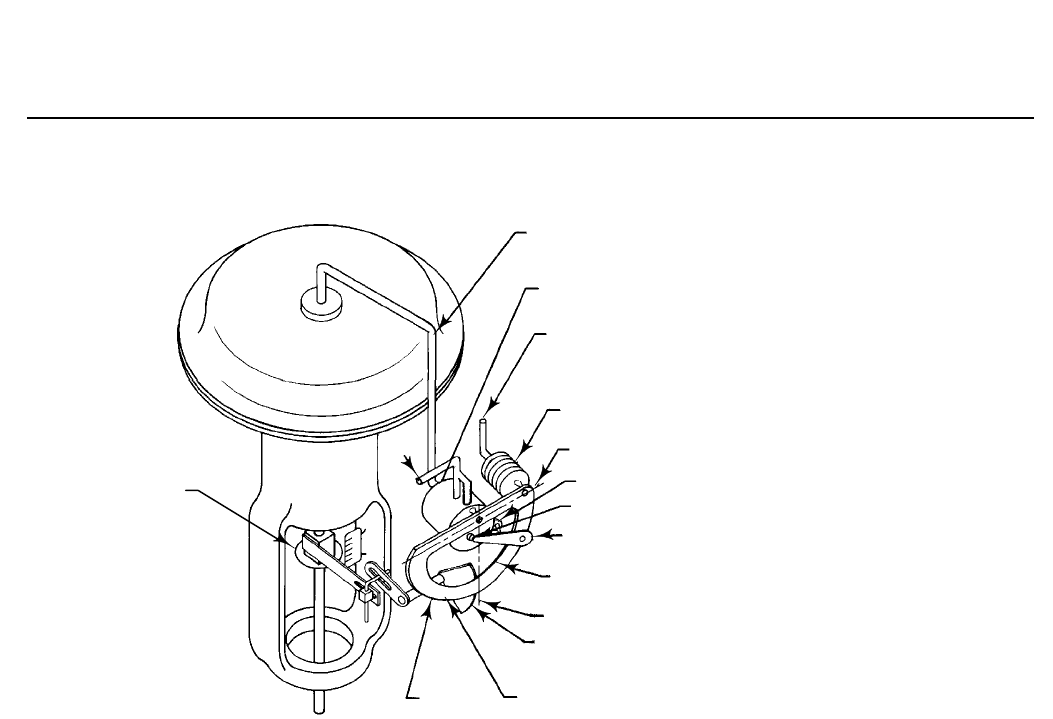
Features
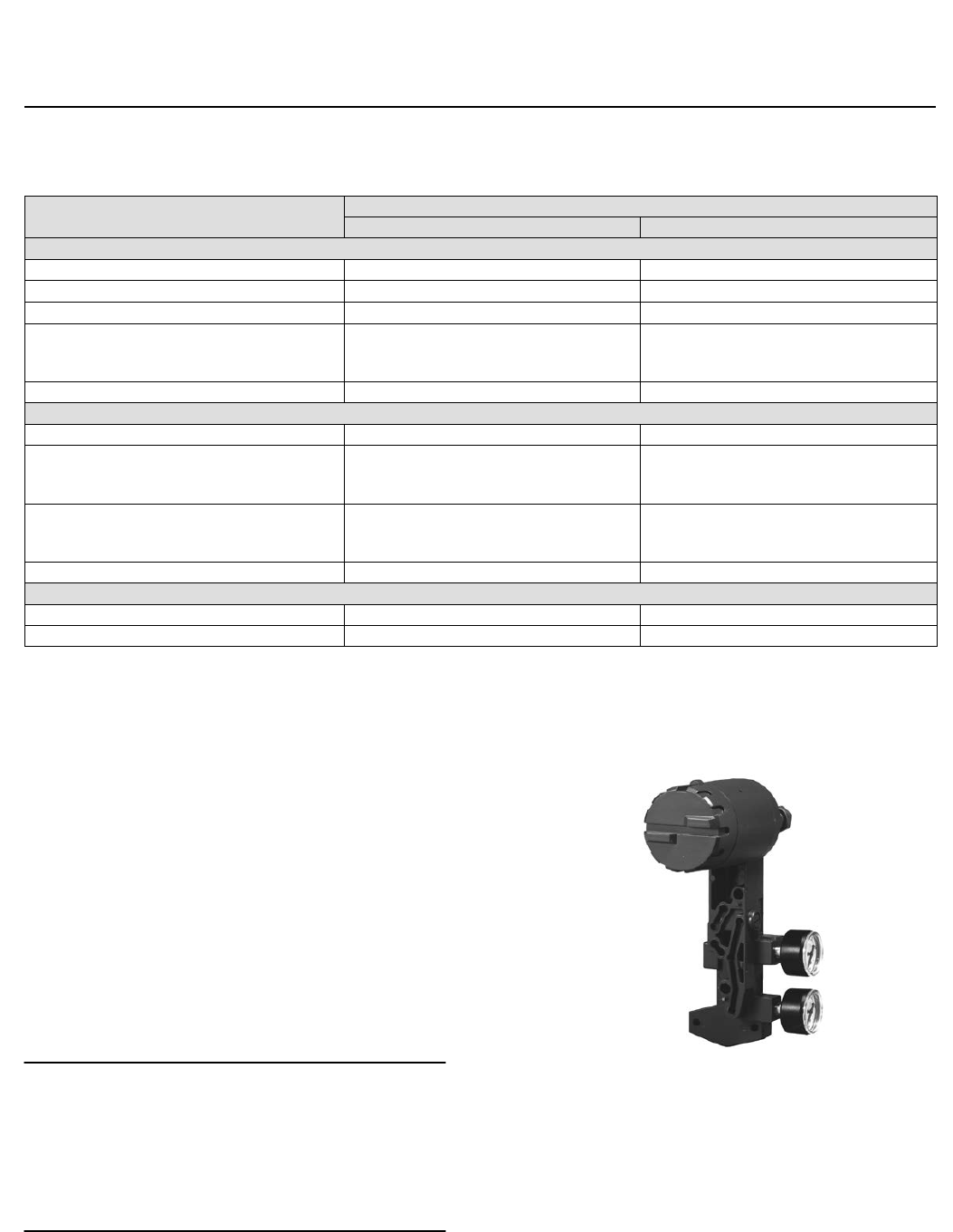
n Versatile Modular Design—3582 positioners can be
upgraded in the field to an electro-pneumatic 3582i
by replacing the gauge block with the 582i
electro-pneumatic converter (figure 3) assembly.
The converter assembly attaches to the positioner
case, providing a cost-effective conversion. Thus, in
the field, 3582 positioners can be upgraded from
pneumatic to electronic to match new control
strategies.
Note
Upgrading existing 3582 positioners by field installation of a
582i electro-pneumatic converter may require changing the
existing positioner mounting and the input signal range.
Contact your Emerson Process Management sales office
when planning an upgrade.
Figure 3. Fisher 582i Electro-Pneumatic Converter
W6120
n Accurate, Efficient, Vibration-Resistant
Operation—3582 and 3582i positioners offer a
field-proven positioner design which is accurate,
fast-responding and able to withstand the
vibrations of most plant environments. Low
steady-state air consumption contributes to
efficient operation.
3582 and 3582i Positioners
D200062X012
Product Bulletin
62.1:3582
February 2015
6
n Rangeability—Both 3582 and 3582i positioners
provide split range capabilities. The range of the
adjustable zero and span permits the use of all
standard input signals including split ranges.
n Simplified Spare Parts Inventories—Because units
from one positioner family can be used in a variety
of control applications, basic spare parts inventory
requirements are simplified and fewer spare parts
are needed to support a plant-wide positioner
applications base.
n Easy Positioner Adjustments—With the cover
removed, as shown in figure 4, zero and span
adjustments are easily accessible and can be made
with a screw driver.
n Stable Operation—Changes in supply pressure and
valve load have minimal effect on positioner
operation.
n Corrosion Resistance—Case, components, and
gasket materials withstand harsh environments.
Positioner bleed air purges internal parts for
additional protection.
n Field Reversible—Simple adjustments permit
switching between direct and reverse action.
n Control Valve Diagnostic Testing Capability—To
support diagnostic testing of
valve/actuator/positioner packages with the
FlowScannert valve diagnostic system,
connectors, piping, and other hardware can be
installed between the 3582 or 3582i and the
actuator.
Type Number Description
3582—Pneumatic valve positioner with bypass and
instrument, supply, and output pressure gauges.
3582A—Pneumatic valve positioner without bypass
and without pressure gauges.
3582C—Pneumatic valve positioner without bypass
and with automotive tire valves instead of pressure
gauges.
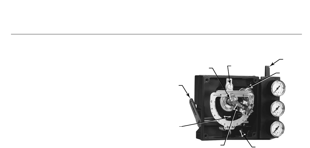
Figure 4. Fisher 3582 Pneumatic Valve Positioner
Mechanism BYPASS
LEVER
BELLOWS
ADJUSTING
SCREW
NOZZLE
ROTARY
SHAFT
ARM
OPERATING
CAM
FLAPPER SCREENED
VENT
W6366
3582D—Pneumatic valve positioner with bypass and
with automotive tire valves instead of pressure
gauges.
3582G—Pneumatic valve positioner without bypass
and with instrument, supply, and output pressure
gauges.
3582NS—Pneumatic valve positioner for nuclear
service applications with or without bypass and with
automotive tire valves instead of pressure gauges.
3582i—Electro-pneumatic valve positioner without
bypass; with 582i converter; and with: Jsupply and
output pressure gauges, Jautomotive tire valves, or
Jpipe plugs.
582i—Electro-pneumatic converter with: Jsupply and
output pressure gauges, Jautomotive tire valves, or
Jpipe plugs. Used for conversion of a 4-20
milliampere input signal to a 0.2 to 1.0 bar (3 to 15
psig) input signal for the pneumatic valve positioner.
83L—Pneumatic relay included as part of both 3582
and 3582i positioners.
Principle of Operation
3582 positioners (3582, 3582NS and 3582A, C, D, and
G pneumatic valve positioners) accept a pneumatic
input signal from a control device. The operational
schematic in figure 5 depicts the direct-acting
pneumatic valve positioner.
3582 and 3582i Positioners
D200062X012
Product Bulletin
62.1:3582
February 2015
7
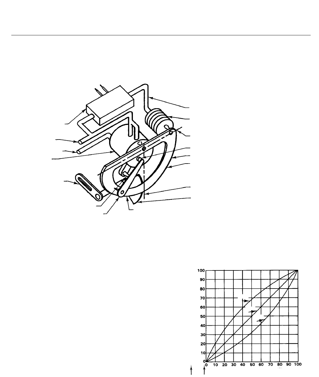
Figure 5. Fisher 3582 Positioner Schematic Diagram
OUTPUT TO DIAPHRAGM
RELAY
INSTRUMENT
BELLOWS
FEEDBACK AXIS
PIVOT
NOZZLE
FLAPPER
DIRECT ACTION QUADRANT
INPUT AXIS
CAM
REVERSE ACTION QUADRANT
BEAM
ACTUATOR
VALVE STEM
CONNECTION
SUPPLY
22A7965-A
A2453-2
Supply pressure is connected to the 83L relay. A fixed
restriction in the relay limits flow to the nozzle so that
when the flapper is not restricting the nozzle, air can
bleed out faster than it is being supplied.
The input signal from the control device is connected
to the bellows. When the input signal increases, the
bellows expands and moves the beam. The beam
pivots about the input axis moving the flapper closer
to the nozzle. The nozzle pressure increases and,
through relay action, increases the output pressure to
the diaphragm actuator. The increased output
pressure to the actuator causes the actuator stem to
move downward. Stem movement is fed back to the
beam by means of a cam. As the cam rotates, the
beam pivots about the feedback axis to move the
flapper slightly away from the nozzle. The nozzle
pressure decreases and reduces the output pressure to
the actuator. Stem movement continues, backing the
flapper away from the nozzle, until equilibrium is
reached.
When the input signal decreases, the bellows
contracts (aided by an internal range spring) and the
beam pivots about the input axis to move the flapper
away from the nozzle. Nozzle pressure decreases and
the relay permits the release of diaphragm casing
pressure to atmosphere. The actuator stem moves
upward. Through the cam, stem movement is fed back
to the beam to reposition the flapper closer to the
nozzle. When equilibrium conditions are obtained,
stem movement stops and the flapper is positioned to
prevent any further decrease in diaphragm case
pressure.
The principle of operation for reverse acting units is
similar except that as the input signal increases, the
diaphragm casing pressure is decreased. Conversely, a
decreasing input signal causes an increase in the
pressure to the diaphragm casing.
As shown in figure 6, the 3582i electro-pneumatic
positioner accepts a DC current input signal provided
to the 582i electro-pneumatic converter attached to
the positioner. The 582i provides the pneumatic input
signal pressure used by the pneumatic positioner.
3582 and 3582i Positioners
D200062X012
Product Bulletin
62.1:3582
February 2015
8
Figure 6. Fisher 3582i Positioner Schematic Diagram
4-20 MILLIAMPERE -
INPUT SIGNAL +
582i
CONVERTER
SUPPLY
OUTPUT TO
ACTUATOR
RELAY
ROTARY
SHAFT ARM
PIVOT
FLAPPER ASSEMBLY
PNEUMATIC SIGNAL
FROM CONVERTER
BELLOWS
FEEDBACK
AXIS
NOZZLE
BEAM
DIRECT ACTING
QUADRANT
INPUT AXIS
CAM
REVERSE ACTING
QUADRANT
A4818-2
Characterized Cams
Three cams are available for 3582 valve positioners. A
linear cam (cam A) is supplied with the unit. Two
characterized cams (cams B and C) are available as
options. Figure 7 shows the resultant stem travel due
to an incremental instrument pressure change for each
cam. When the linear cam is the operating cam, there
is a linear relationship between an incremental input
signal change and valve travel, and the flow
characteristic of the valve is that of the control valve.
When either characterized cam is the operating cam,
the relationship between an incremental input signal
change and valve travel changes thereby modifying
the valve flow characteristics. Figure 8 shows how the
characteristic is modified for an equal percentage
valve. Figure 9 shows how the characteristic is
modified for a linear valve.
Because 3582 positioners mount the same way on
either direct-acting or reverse-acting diaphragm
actuators, the cams are reversible.
Figure 7. Instrument Pressure Versus Valve Travel
PERCENT INSTRUMENT PRESSURE SPAN
PERCENT VALVE STEM TRAVEL
0 PERCENT CORRESPONDS TO
MINIMUM DIAPHRAGM PRESSURE
0
10
20
30
40
50
60
70
80
90
100
REVERSE
ACTING
POSITIONER
DIRECT
ACTING
POSITIONER
CAM
C
CAM
A
CAM
B
CK4832-A
A1413
3582 and 3582i Positioners
D200062X012
Product Bulletin
62.1:3582
February 2015
9
Figure 8. Equal Percentage Valve Flow Characteristics
as Modified by Various Cams
PERCENT INSTRUMENT PRESSURE SPAN
REVERSE
ACTING
POSITIONER
DIRECT
ACTING
POSITIONER
CAM
C
CAM
C
CAM
A
CAM
A
CAM
B
CAM
B
NORMALLY
CLOSED
VALVE
NORMALLY
OPEN
VALVE
PERCENT FLOW
VALVE PLUG AT CONSTANT
PRESSURE DROP
CK4835-A
A1415-1
0
10
20
30
40
50
60
70
80
90
100
Figure 9. Linear Valve Flow Characteristics as
Modified by Various Cams
PERCENT INSTRUMENT PRESSURE SPAN
REVERSE
ACTING
POSITIONER
DIRECT
ACTING
POSITIONER
NORMALLY
OPEN
VALVE
NORMALLY
CLOSED
VALVE
CAM
C
CAM
C
CAM
A
CAM
A
CAM
B
CAM
B
PERCENT FLOW
VALVE PLUG AT CONSTANT PRESSURE DROP
CK4833-A
A1414
0
10
20
30
40
50
60
70
80
90
100
Installation
Figure 10 shows a typical positioner mounting for a
direct- or reverse-acting actuator. Positioner overall
dimensions and connections are shown in figure 10
and table 4.
Ordering Information
When ordering, please specify the product application
and construction:
Application
1. Positioner type number. When ordering a 3582i
electro-pneumatic positioner, specify: Jsupply and
output pressure gauges, Jautomotive tire valves,
or Jpipe plugs
2. Maximum supply pressure available
3. Direct or reverse acting
4. Valve stroke in inches; actuator type and size
5. Initial cam set-up (cam A, B, or C)
6. Input signal
7. Supply pressure regulator and test pressure gauge
8. Connectors for diagnostic testing, if required
Construction
Refer to the specifications. Carefully review each
specification; indicate your choice whenever a
selection is offered.
3582 and 3582i Positioners
D200062X012
Product Bulletin
62.1:3582
February 2015
10
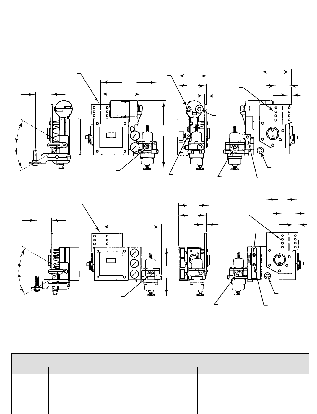
Figure 10. Valve Positioner Dimensions and Connections (see table 4 for the X dimension)
X
30_ MAX
30_ MAX
CL OF ACTUATOR
246.1
(9.69)
1/4-18 NPT
OUTLET CONN
PLUGGED
1/4-18 NPT
VENT CONN
1/4-18 NPT
OUTPUT CONN
11.44
(291)
1/2-14 NPT
CONDUIT
CONN
1/4-18 NPT
SUPPLY CONN
3/8-18 NPT
VENT CONN
30_ MAX
30_ MAX
X
CL OF ACTUATOR
261
(10.26)
205
(8.06)
1/4-18 NPT
OUTLET CONN
PLUGGED 1/4-18 NPT
SUPPLY CONN 1/4-18 NPT
OUTPUT CONN
3/8-18 NPT
VENT CONN
1/4-18 NPT
INSTR CONN
0.34 ∅ HOLES
SPACED 0.69
APART
141
(5.56)
127
(5.00)
7.9
(0.31)
140
(5.50)
57.2
(2.25)
12.7
(0.50)
mm
(INCH)
FISHER 3582i
FISHER 3582
(DIMENSIONS FOR 3582A, C, D, AND G ARE THE SAME)
11B6520-F
B2211-3
11B6519-G
182.6
(7.19) 7.9
(0.31)
141
(5.56)
127
(5.00)
0.34 ∅ HOLES
SPACED 0.69
APART
140
(5.50)
57.2
(2.25)
12.7
(0.50)
1/4-18 NPT
OPTIONAL OUTPUT
CONN PLUGGED
Table 4. Dimensions
STEM TRAVEL X
9.5 mm (0.375 inch) Stem 12.7 mm (0.50 inch) Stem 19.1 mm (0.75 inch) Stem
mm Inch mm Inch mm Inch mm Inch
29 or less
38
51
64
76
1.125 or less
1.50
2
2.50
3
81
90
102
113
124
3.19
3.56
4.00
4.44
4.88
87
97
108
119
130
3.44
3.81
4.25
4.69
5.12
100
109
121
132
143
3.94
4.31
4.75
5.19
5.62
89
102
3.50
4
135
146
5.31
5.75
141
152
5.56
6.00
154
165
6.06
6.50

3582 and 3582i Positioners
D200062X012
Product Bulletin
62.1:3582
February 2015
11
Table 5. Hazardous Area Classifications for Fisher 582i Converter(1)—CSA (Canada)
Certification Body Certification Obtained Entity Rating Temperature Code
CSA
Intrinsically Safe
Ex ia IIC T4/T5/T6 per drawing GE28591
Ex ia Intrinsically Safe
Class I, II Division 1 GP A,B,C,D,E,F,G T4/T5/T6
per drawing GE28591
Vmax = 30 VDC
Imax = 150 mA
Pi = 1.25 W
Ci = 0 nF
Li = 0 mH
T4 (Tamb ≤ 71°C)
T5 (Tamb ≤ 62°C)
T6 (Tamb ≤ 47°C)
Explosion-proof
Ex d IIC T6
Class I, Division I, GP A,B,C,D T6
- - - T6 (Tamb ≤ 71°C)
Type n
Ex nA IIC T6 - - - T6 (Tamb ≤ 71°C)
Class I, Division 2, GP A,B,C,D T6
Class II, Division 1 GP E,F,G T6
Class II Division 2 GP F,G T6
- - - T6 (Tamb ≤ 71°C)
1.These hazardous area classification also apply to 3582i positioners.
Table 6. Hazardous Area Classifications for Fisher 582i Converter(1)—FM (United States)
Certification Body Certification Obtained Entity Rating Temperature Code
FM
Intrinsically Safe
Class I Zone 0 AEx ia IIC T4/T5/T6 per drawing GE28590
Class I, II, III Division 1 GP A,B,C,D,E,F,G T4/T5/T6 per
drawing GE28590
Vmax = 30 VDC
Imax = 150 mA
Pi = 1.25 W
Ci = 0 nF
Li = 0 mH
T4 (Tamb ≤ 71°C)
T5 (Tamb ≤ 62°C)
T6 (Tamb ≤ 47°C)
Explosion-proof
Class I Zone 1 AEx d IIC T6
Class I, Division I, GP A,B,C,D T6
- - - T6 (Tamb ≤ 71°C)
Type n
Class I Zone 2 AEx nA IIC T6 - - - T6 (Tamb ≤ 71°C)
Class I Division 2, GP A,B,C,D T6
Class II Division 1, GP E,F,G T6
Class II Division 2, GP F,G T6
- - - T6 (Tamb ≤ 71°C)
1.These hazardous area classification also apply to 3582i positioners.
Table 7. Hazardous Area Classifications for Fisher 582i Converter(1)—ATEX
Certificate Certification Obtained Entity Rating Temperature Code
ATEX
II 1 G & D
Intrinsically Safe
Gas
Ex ia IIC T4/T5/T6 Ga
Ui = 30 VDC
Ii = 150 mA
Pi = 1.25 W
Ci = 0 nF
Li = 0 mH
T4 (Tamb ≤ 71°C)
T5 (Tamb ≤ 62°C)
T6 (Tamb ≤ 47°C)
Dust
Ex ia IIIC Da T109°C (Tamb ≤ 71°C) / T100°C (Tamb ≤ 62°C)
/ T85°C (Tamb ≤ 47°C)
- - -
II 2 G & D
Flameproof
Gas
Ex d IIC T6 Gb
- - - T6 (Tamb ≤ 71°C)
Dust
Ex tb IIIC Db T74°C (Tamb ≤ 71°C) - - -
II 3 G & D
Type n
Gas
Ex nA IIC T6 Gc - - -
T6 (Tamb ≤ 71°C)
Dust
Ex tc IIIC Dc T85°C (Tamb ≤ 71°C) - - -
1.These hazardous area classification also apply to 3582i positioners.

3582 and 3582i Positioners
D200062X012
Product Bulletin
62.1:3582
February 2015
12
Table 8. Hazardous Area Classifications for Fisher 582i Converter(1)—IECEx
Certificate Certification Obtained Entity Rating Temperature Code
IECEx
Intrinsically Safe
Gas
Ex ia IIC T4/T5/T6 Ga
Ui = 30 VDC
Ii = 150 mA
Pi = 1.25 W
Ci = 0 nF
Li = 0 mH
T4 (Tamb ≤ 71°C)
T5 (Tamb ≤ 62°C)
T6 (Tamb ≤ 47°C)
Flameproof
Gas
Ex d IIC T6 Gb
- - - T6 (Tamb ≤ 71°C)
Type n
Gas
Ex nA IIC T6 Gc
- - - T6 (Tamb ≤ 71°C)
1.These hazardous area classification also apply to 3582i positioners.
Emerson Process Management
Marshalltown, Iowa 50158 USA
Sorocaba, 18087 Brazil
Chatham, Kent ME4 4QZ UK
Dubai, United Arab Emirates
Singapore 128461 Singapore
www.Fisher.com
The contents of this publication are presented for informational purposes only, and while every effort has been made to ensure their accuracy, they are not
to be construed as warranties or guarantees, express or implied, regarding the products or services described herein or their use or applicability. All sales are
governed by our terms and conditions, which are available upon request. We reserve the right to modify or improve the designs or specifications of such
products at any time without notice.
E 1989, 2015 Fisher Controls International LLC. All rights reserved.
Fisher and FlowScanner are marks owned by one of the companies in the Emerson Process Management business unit of Emerson Electric Co. Emerson
Process Management, Emerson, and the Emerson logo are trademarks and service marks of Emerson Electric Co. All other marks are the property of their
respective owners.
Neither Emerson, Emerson Process Management, nor any of their affiliated entities assumes responsibility for the selection, use or maintenance
of any product. Responsibility for proper selection, use, and maintenance of any product remains solely with the purchaser and end user.
