Emerson Fisher 3610J Data Sheet D200064X012_Feb15_AQ
2015-03-30
: Emerson Emerson-Fisher-3610J-Data-Sheet-681664 emerson-fisher-3610j-data-sheet-681664 emerson pdf
Open the PDF directly: View PDF ![]() .
.
Page Count: 12
www.Fisher.com
Fisherr 3610J and 3620J Positioners and 3622
Electro-Pneumatic Converter
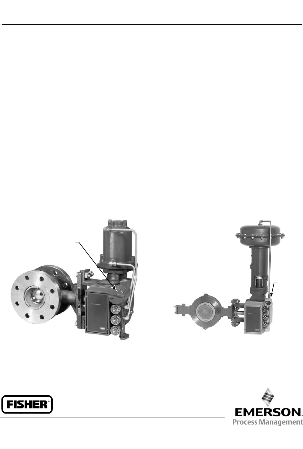
Fisher 3610J or 3610JP pneumatic and 3620J or 3620JP
electro-pneumatic positioners are used in combination
with either single or double-acting rotary actuators to
accurately position control valves used in throttling
applications. The positioner mounts integrally to the
actuator housing. These rugged positioners provide a
valve position proportional to a pneumatic or a DC
current input signal.
The 3610J or 3610JP pneumatic positioner in
combination with the Fisher 3622 electro-pneumatic
converter becomes the 3620J or 3620JP positioner,
respectively. This integral electro-pneumatic
converter, can be factory installed or installed in the
field on existing positioners. The electro-pneumatic
converter receives the DC current input signal and
provides a proportional pneumatic output signal
through a nozzle/flapper arrangement.
The output signal from the converter becomes the
input signal pressure to the pneumatic positioner,
eliminating the need for a remote mounted
transducer.
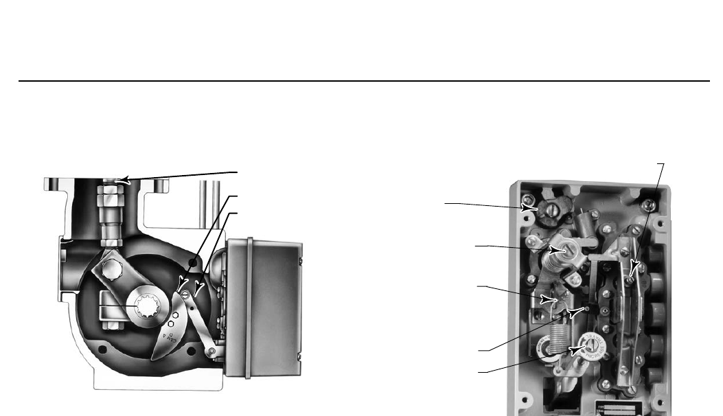
The positioner mounts on the actuator as shown
below. Figure 1 shows the cam feedback mechanism
for a positioner mounted on the actuator. Positioner
bleed air continually purges the enclosure containing
the feedback lever and the feedback linkages.
To support diagnostic testing of
valve/actuator/positioner packages, connectors,
piping, and other hardware can be installed between
the 3610J or 3620J positioner and the actuator.
W4920-1
ELECTRO-
PNEUMATIC
CONVERTER
FISHER 3620JP ELECTRO-PNEUMATIC POSITIONER
WITH 1061 ACTUATOR AND V500 VALVE
W3949
BYPASS
VALVE
FISHER 3610J PNEUMATIC POSITIONER WITH
1052 ACTUATOR AND ECCENTRIC DISC VALVE
3610J and 3620J Positioners
D200064X012
Product Bulletin
62.1:3610
February 2015

3610J and 3620J Positioners
D200064X012
Product Bulletin
62.1:3610
February 2015
2
Specifications
Available Configurations
Refer to the following type number description on
page 6
Input Signal
3610J or 3610JP:
Standard: J0.2 to 1.0 bar (3 to 15 psig), J0.4 to 2.0
bar (6 to 30 psig), or Jsplit range, see table 1.
Adjustable: Zero is adjustable from 0.07 to 1.5 bar
(1 to 22 psig) for standard valve rotations. Span is
adjustable from 0.2 to 2.0 bar (3.2 to 28.8 psi) for
standard valve rotations. Location of adjustments are
shown in figure 2.
3620J and 3620JP:
4-20 mA DC constant current with 30 VDC maximum
compliance voltage. Minimum terminal voltage is
2.4 VDC at 20 mA. Split range is also available,
see table 1.
Output Signal
Pneumatic pressure as required by the actuator up to
full supply pressure
Action(1): Field-reversible between Jdirect and
Jreverse within the pneumatic positioner
Equivalent Circuit
3620J and 3620JP: 120 ohms shunted by three 5.6 V
zener diodes
Typical Performance
Independent Linearity:
Direct-Acting 3610J and 3620J: ±1.5% of output span
Reverse-Acting 3610J and 3620J: ±0.75% of output span
Direct-Acting 3610JP and 3620JP: ±1.25% of output
span
Reverse-Acting 3610JP and 3620JP: ±0.5% of output
span
Hysteresis:
3610J: 1.0% of output span
3620J: 0.75% of output span
3610JP: 0.5% of output span
3620JP: 0.6% of output span
Deadband: 0.1% of input span
Electromagnetic Compliance for 3622
electro-pneumatic converter:
Meets EN 61326-1 (First Edition)
Immunity—Industrial locations per Table 2 of
the EN 61326-1 standard. Performance is
shown in table 2 below.
Emissions—Class A
ISM equipment rating: Group 1, Class A
Note:The Electromagnetic Compliance specifications
also apply to 3620J positioners
Maximum Supply Air Demand(2)
3610J and 3620J:
1.4 bar (20 psig) Supply: 13 normal m3/hour (490 scfh)
2.4 bar (35 psig) Supply: 17 normal m3/hour (640 scfh)
3610JP and 3620JP:
5.2 bar (75 psig) Supply: 37 normal m3/hour
(1380 scfh)
6.9 bar (100 psig) Supply: 46 normal m3/hour
(1700 scfh)
Operating Influences
Supply Pressure Sensitivity: A 10% change in supply
pressure changes the valve shaft position less than
the following percentages of valve rotation:
3610J and 3620J: 1.0% at 1.4 bar (20 psig) supply
pressure
3610JP and 3620JP: 1.5% at 4.1 bar
(60 psig) supply pressure
Supply Pressure(3)
Minimum Recommended: 0.3 bar (5 psig) above
actuator requirement [1.4 bar (20 psig) for a 0.2 to
1.0 bar (3 to 15 psig) nominal actuator signal; 2.4 bar
(35 psig) for a 0.4 to 2.0 bar (6 to 30 psig) nominal
actuator signal].
Maximum: 10.3 bar (150 psig) or maximum pressure
rating of the actuator, whichever is lower.
Supply Medium: Air or natural gas(4).
3620J and 3620JP are not approved for use with
natural gas as the supply medium
- continued -
3610J and 3620J Positioners
D200064X012
Product Bulletin
62.1:3610
February 2015
3
Specifications (continued)
Steady-State Air Consumption(2)
3610J: 0.40 normal m3/hour (15 scfh) at 1.4 bar
(20 psig) supply pressure
3610JP: 0.64 normal m3/hour (24 scfh) at 6.9 bar
(100 psig) supply pressure
3620J: 0.49 normal m3/hour (18 scfh) at 1.4 bar
(20 psig) supply pressure
3620JP: 0.93 normal m3/hour (35 scfh) at 6.9 bar
(100 psig) supply pressure
Operative Temperature Limits(3)
-40 to 82_C (-40 to 180_F)
Electrical Classification for 3622
Hazardous Area:
CSA— Intrinsically Safe, Explosion proof, Type n
Dust-Ignition proof, Division 2
FM— Intrinsically Safe, Explosion proof, Type n,
Non-incendive, Dust-Ignition proof,
ATEX— Intrinsically Safe, Type n, Flameproof
IECEx— Intrinsically Safe, Type n, Flameproof
(Gas Atmospheres Only)
Refer to tables 3, 4, 5, and 6 for additional
information.
Note: These classifications also apply to 3620J
positioners
Housing Classification for 3622
CSA— Type 3 Encl.
FM— NEMA 3, IP54
ATEX— IP64
IECEx— IP54
Mount instrument with vent on side or bottom if
weatherproofing is a concern.
Note: These classifications also apply to 3620J
positioners
Other Classifications/Certifications for 3622
CUTR— Customs Union Technical Regulations (Russia,
Kazakhstan, and Belarus)
INMETRO— National Institute of Metrology, Quality
and Technology (Brazil)
KGS— Korea Gas Safety Corporation (South Korea)
Contact your Emerson Process Management sales
office for classification/certification specific
information
Note: These classifications also apply to 3620J
positioners
Hazardous Area Classification for 3610J Positioners
Complies with the requirements of ATEX Group II
Category 2 Gas and Dust
Meets Customs Union technical regulation TP TC
012/2011 for Groups II/III Category 2 equipment
II Gb c T*X
III Db c T*X
Note: These ratings do not apply to 3620J positioners
Construction Materials
All Positioners:
Case: Low copper aluminum alloy
Cover: Polyester plastic
Feedback Lever: Stainless steel
Range Spring: Zinc-plated steel
Input Module and Relay Diaphragms: Nitrile and
polyester
Relay Valve Plugs and Seats: Stainless steel
Tubing: Copper (standard)
Fittings: Brass (standard)
Gauges: Chrome-plated brass connection with plastic
case
3620J and 3620JP:
Housing and Cap: Low copper aluminum alloy
Pressure Connections
1/4 NPT internal
- continued -

3610J and 3620J Positioners
D200064X012
Product Bulletin
62.1:3610
February 2015
4
Specifications (continued)
Rotary Valve Rotation
60, 75, or 90 degrees
Characterized Cams
See Characterized Cams section
Electrical Connection for 3620J and 3620JP
1/2-14 NPT Conduit Connection
Options
3610J and 3610JP:
JSupply pressure gauge, Jtire valves, or Jplugs,
JIntegral mounted bypass valve on 3610J only
3620J and 3620JP:
JSupply pressure gauge, Jtire valves, or Jplugs
Approximate Weight
3610J positioners: 2.5 kg (5.6 pounds)
3620J positioners: 3.6 kg (8.0 pounds)
NOTE: Specialized instrument terms are defined in ANSI/ISA Standard 51.1 - Process Instrument Terminology.
1. For direct action, an increasing input signal extends the actuator rod. For reverse action, an increasing input signal retracts the actuator rod.
2. Normal m3/hr--normal cubic meters per hour (0_C and 1.01325 bar absolute). Scfh--standard cubic feet per hour (60_F and 14.7 psia).
3. The pressure and temperature limits in this document and any applicable standard or code limitation should not be exceeded.
4. Natural gas should contain no more than 20 ppm of H2S.
Table 1. Split-Range Capabilities
3610J AND 3610JP POSITIONERS(1)
Split 0.2 to 1.0 Bar (3 to 15 Psig) Input Signal 0.4 to 2.0 Bar (6 to 30 Psig) Input Signal
Bar Psig Bar Psig
Two-way 0.2 to 0.6
0.6 to 1.0
3 to 9
9 to 15
0.4 to 1.2
1.2 to 2.0
6 to 18
18 to 30
Three-way
0.2 to 0.5
0.5 to 0.7
0.7 to 1.0
3 to 7
7 to 11
11 to 15
0.4 to 0.9
0.9 to 1.5
1.5 to 2.0
6 to 14
14 to 22
22 to 30
3620J AND 3620JP POSITIONERS(1)
Split 4-20 Milliampere Input Signal
Two-way 4 to 12
12 to 20
Three-way
4 to 9.3
9.3 to 14.7
14.7 to 20
1. This table is only valid for the following standard valve rotations/range spring combinations: 90_/18A7845X012 (blue), 75_/18A7846X012 (yellow), and 60_/18A5118X012 (red). Contact
your Emerson Process Management sales office or the factory for input signal ranges not listed.
Table 2. Fisher 3622 Electro-Pneumatic Converter(1) EMC Summary Results—Immunity
Port Phenomenon Basic Standard Test Level Performance
Criteria(2)
Enclosure
Electrostatic Discharge (ESD) IEC 61000-4-2 4 kV contact; 8 kV air A
Radiated EM field IEC 61000-4-3
80 to 1000 MHz @ 10V/m with 1 kHz AM at 80%
1400 to 2000 MHz @ 3V/m with 1 kHz AM at 80%
2000 to 2700 MHz @ 1V/m with 1 kHz AM at 80%
A
Rated power frequency
magnetic field IEC 61000-4-8 60 A/m at 50 Hz A
I/O signal/control
Burst (fast transients) IEC 61000-4-4 1 kV A
Surge IEC 61000-4-5 1 kV (line to ground only, each) B
Conducted RF IEC 61000-4-6 150 kHz to 80 MHz at 3 Vrms A
Specification limit = ±1% of span
1. The information contained in the table also applies to 3620J, 3620JP, and 3621JP electro-pneumatic positioners.
2. A=No degradation during testing. B = Temporary degradation during testing, but is self-recovering.
3610J and 3620J Positioners
D200064X012
Product Bulletin
62.1:3610
February 2015
5
Figure 1. Typical Fisher 3610J and 3620J Positioner
Mounting
ACTUATOR ROD
CAM
FEEDBACK
LEVER
W3783
Features
n Accurate, Efficient, Vibration-Resistant
Operation—The positioner provides accurate,
fast-response and can withstand the vibrations of
most plant environments. Low steady-state air
consumption contributes to efficient operation.
n Modular Design— The pneumatic 3610J positioner
easily converts to an electro-pneumatic 3620J
positioner by replacing the existing gauge block
with the 3622 electro-pneumatic converter
assembly. The converter assembly attaches to the
existing positioner, providing a simple, compact,
and cost-effective conversion.
n Versatility—3610J and 3610JP positioners accept a
pneumatic input signal and 3620J and 3620JP
positioners accept a DC current input signal from a
control device. The pneumatic and
electro-pneumatic positioners provide split range
capabilities and adjustable zero and span. The
rangeability of the positioner zero and span permits
using a single range spring for all standard input
signals including split ranges.
Figure 2. Adjustments for Fisher 3610J and 3620J
Positioners
ZERO
ADJUSTMENT
W4900-1
COARSE SPAN
ADJUSTMENT
MINOR LOOP
GAIN
ADJUSTMENT
FINE SPAN
ADJUSTMENT
CROSSOVER
ADJUSTMENT
DIRECT/
REVERSE
PLATE
n Fewer Spare Parts—Most of the parts for 3610J and
3610JP or 3620J and 3620JP positioners are
interchangeable, requiring fewer spare parts to
support these positioners.
n Easy Positioner Adjustments—With the cover
removed, zero, span, and cross-over adjustments,
shown in figure 2, are easily accessible and can be
made with a screwdriver.
n Application Flexibility—Easily adjustable minor loop
gain fine tunes the positioner to optimize dynamic
response for each specific actuator size and
application.
n Stable Operation—Changes in supply pressure have
minimal effect on positioner operation.
n Corrosion Resistant—Case, components, and gasket
materials withstand harsh environments. Positioner
bleed air purges internal parts and actuator housing
for additional protection.
n Field Reversible—Simple adjustments permit
switching between direct and reverse action; no
additional parts are required.
3610J and 3620J Positioners
D200064X012
Product Bulletin
62.1:3610
February 2015
6
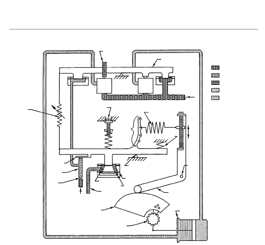
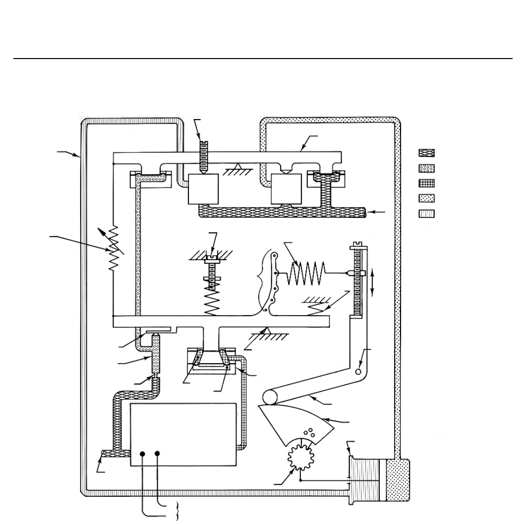
Figure 3. Schematic of Fisher 3610JP Positioner
38A8900-B
B1845-1
MINOR LOOP
GAIN ADJ ZERO ADJ
RANGE SPRING
COARSE
SPAN
ADJ
CROSS-OVER
ADJ RELAY BEAM
RELAY
B
RELAY
A
SUPPLY PRESSURE
NOZZLE PRESSURE
INPUT SIGNAL
OUTPUT SIGNAL
OUTPUT SIGNAL
AIR
SUPPLY
FINE
SPAN
ADJ
PIVOT
B
FEEDBACK
LEVER
INPUT MODULE
PIVOT A
FLAPPER
NOZZLE
FIXED
RESTRICTION
AIR SUPPLY
CAVITY A
CAVITY B
INPUT SIGNAL
PRESSURE
POSITIONER CAM
END VIEW OF
ROTARY SHAFT
PISTON
ACTUATOR
SUMMING BEAM
COUNTER SPRING
Type Number
Description1
The following descriptions provide specific
information on the different positioner constructions.
3610J: A single-acting pneumatic rotary valve
positioner for use with Fisher 1051 and 1052
actuators.
3610JP: A double-acting pneumatic rotary valve
positioner for use with Fisher 1061 and 1069
actuators.
3620J: A single-acting electro-pneumatic rotary valve
positioner for use with 1051 and 1052 actuators.
3620JP: A double-acting electro-pneumatic rotary
valve positioner for use with 1061 and 1069 actuators.
3622: An electro-pneumatic converter that converts a
4-20 mA DC input signal to a 3 to 15 psig (0.2 to 1.0
bar) input signal for the pneumatic positioner.
Combining this unit with a 3610J or 3610JP positioner
produces a 3620J or 3620JP positioner, respectively.
Principle of Operation
3610J positioners accept a pneumatic input signal and
3620J positioners accept a DC current input signal
from a control device.
3610J and 3620J Positioners
D200064X012
Product Bulletin
62.1:3610
February 2015
7
Figure 4. Schematic of Fisher 3620JP Positioner
38A8900-B
B2148
FOR 3620JP
ONLY
MINOR LOOP
GAIN ADJ
FLAPPER
NOZZLE
FIXED
RESTRICTION
CROSS-OVER
ADJ
RELAY BEAM
RELAY
A
RELAY
B
SUMMING BEAM
AIR
SUPPLY
FINE
SPAN
ADJ
PIVOT
B
FEEDBACK
LEVER
POSITIONER
CAM
RANGE SPRING
COUNTER SPRING
COARSE
SPAN
ADJ
INPUT MODULE
PIVOT A
CAVITY A
CAVITY B
ZERO ADJ
PISTON
ACTUATOR
CONVERTER
MODULE
SUPPLY
END VIEW OF ROTARY SHAFT
4-20 MILLIAMPERE INPUT SIGNAL
-
+
SUPPLY PRESSURE
NOZZLE PRESSURE
INPUT SIGNAL
OUTPUT SIGNAL
OUTPUT SIGNAL
These positioners are force-balanced instruments that
provide a valve shaft position proportional to the input
signal. The following describes the principle of
operation for 3610JP and 3620JP positioners. The
principle of operation for 3610J and 3620J positioners
is similar except relay A is not used. Refer to figures 3
and 4 while reading the following descriptions.
For direct action, input signal pressure from a control
device is channeled to cavity A in the input module. An
increase in input signal pressure results in a downward
force on the summing beam, pivoting the
summing beam counterclockwise. This moves the
flapper slightly toward the nozzle, increasing the
nozzle pressure. As nozzle pressure increases, the relay
beam pivots clockwise, causing relay B to increase
upper cylinder pressure and relay A to exhaust lower
cylinder pressure of the actuator.
As a result, the actuator rod extends and the actuator
rotary shaft rotates clockwise. This causes the
feedback lever to pivot clockwise and the force applied
to the summing beam by the range spring increases.
This force, which opposes the downward force on the
summing beam caused by the increasing input signal

3610J and 3620J Positioners
D200064X012
Product Bulletin
62.1:3610
February 2015
8
pressure, continues to increase until the summing
beam torques are in equilibrium. At this point, the
valve shaft is in the correct position for the specific
input signal applied.
For reverse action, input signal pressure is channeled
to both cavities A and B. An increase in signal pressure
results in an upward force on the summing beam,
pivoting the summing beam clockwise and causing
relay B to exhaust upper actuator cylinder pressure to
atmosphere and relay A to increase lower actuator
cylinder pressure. As a result, the actuator rod retracts
and the actuator rotary shaft rotates
counterclockwise. This causes the feedback arm to
pivot counterclockwise reducing the force applied to
the summing beam by the range spring.
As the valve shaft rotates counterclockwise, the range
spring force to the summing beam continues to
reduce until the summing beam torques are in
equilibrium. At this point, the valve shaft is in the
correct position for the specific input signal applied.
3620J or 3620JP positioners (figure 4) are a
combination of a 3610J or a 3610JP positioner with a
3622 electro-pneumatic converter. The
electro-pneumatic converter provides a 0.2 to 1.0 bar
(3 to 15 psig) output pressure proportional to the
4-20 mA DC input signal. The 0.2 to 1.0 bar (3 to 15
psig) output pressure becomes the input signal
pressure to the 3610J or 3610JP pneumatic positioner.
Installation
The supply pressure medium must be a clean, dry, and
oil-free air, or noncorrosive gas (3610J positioners
only). If the supply pressure source is capable of
exceeding the maximum actuator operating pressure
or positioner supply pressure, appropriate steps must
be taken during installation to protect the positioner
and all connected equipment against overpressure.
Typical positioner mounting on an actuator is shown
on the front page. Overall dimensions are shown in
figure 5.
Note
3620J and 3620JP positioners are not approved for use with
natural gas as the supply medium.
3610J and 3620J Positioners
D200064X012
Product Bulletin
62.1:3610
February 2015
9
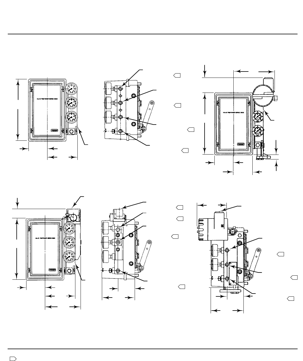
Figure 5. Typical Mounting Dimensions and Connections
208
(8.19)
63.5
(2.50)
GAUGE
BLOCK
INSTRUMENT
CONNECTION
OUTPUT A
CONNECTION
(PLUGGED ON
3610J)
OUTPUT B
CONNECTION
SUPPLY
CONNECTION
49.3
(1.94)
140
(5.50)
63.5
(2.50)
63.5
(2.50)
17.5
(0.69)
3622
100.1
(3.94)
208
(8.19)
208
(8.19)
63.5
(2.50) 100.1
(3.94)
119.1
(4.69)
GAUGE
BLOCK
31.8
(1.25)
BYPASS
VALVE
INSTRUMENT
CONNECTION
OUTPUT A
CONNECTION
(PLUGGED)
OUTPUT B
CONNECTION
110.2
(4.34)
57.2
(2.25)
SUPPLY
CONNECTION
OUTPUT A
CONNECTION
(PLUGGED ON
3620J)
OUTPUT B
CONNECTION
SUPPLY
CONNECTION
103
(4.06)
110.2
(4.34)
57.2
(2.25)
1/2 NPT
CONDUIT
CONNECTION
19A1442-C
19A1444-B
11B2612-C
C0681-2
TYPICAL FISHER 3610J POSITIONER WITHOUT BYPASS VALVE
FISHER 3610J POSITIONER WITH BYPASS ASSEMBLY FISHER 3620J OR 3620JP POSITIONER
Note:
1 Instrument, Output, and Supply connections are 1/4 NPT.
mm
(INCH)
1
1
1
1
1
1
1
1
1
1
1
3610J and 3620J Positioners
D200064X012
Product Bulletin
62.1:3610
February 2015
10
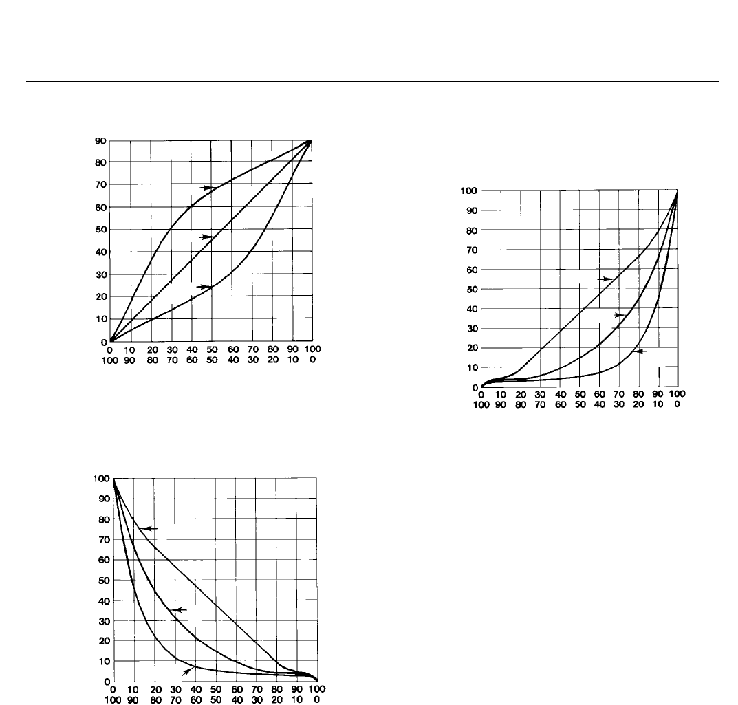
Figure 6. Input Span Versus Valve Rotation
DEGREES OF VALVE ROTATION
DIRECT
REVERSE
PERCENT OF RATED INPUT SPAN
CAM
B
CAM
A
A2264-1
CAM
C
Figure 7. Flow Characteristics for the Various Cams
When Used with an Equal Percentage Characteristic,
Push-Down-to-Close Valve
DIRECT
REVERSE
PERCENT OF RATED INPUT SPAN
CAM
B
CAM
A
CAM
C
33A4960-A
A1582-2
PERCENT OF FLOW
(PRESSURE DROP CONSTANT)
PUSH DOWN TO CLOSE
Characterized Cams
3610J and 3620J positioners are available with any one
of three cams, a linear cam (cam A) or two
characterized cams (cams B and C). Figure 6 shows the
resultant valve rotation due to an incremental
instrument pressure change for the three cams.
Figures 7 and 8 show how the flow characteristics
change when using the cams with a valve that has
equal percentage characteristics.
Figure 8. Flow Characteristics for the Various Cams
When Used with an Equal Percentage Characteristic,
Push-Down-to-Open Valve
DIRECT
REVERSE
PERCENT OF RATED INPUT SPAN
CAM
B
CAM
A
CAM
C
PERCENT OF FLOW
(PRESSURE DROP CONSTANT)
PUSH DOWN TO OPEN
33A4959-A
A1581-2
When the linear cam is the operating cam, there is a
linear relationship between an incremental instrument
pressure change and the resultant valve stem rotation.
The flow characteristic is that of the control valve.
As shown in figure 6, installing either characterized
cam as the operating cam changes the relationship
between the incremental instrument pressure change
and valve stem travel, thereby modifying the valve
flow characteristics.
Ordering Information
When ordering, specify the product application and
construction:
Application
1. Positioner type number
2. Maximum supply pressure available
3. Actuator size and type number
4. Cam characteristic
5. Input signal
Construction
Refer to the specifications. Carefully review each
specification; indicate your choice whenever a
selection is to be made.

3610J and 3620J Positioners
D200064X012
Product Bulletin
62.1:3610
February 2015
11
Table 3. Hazardous Area Classifications for Fisher 3622 Electro-Pneumatic Converter(1)—CSA (Canada)
Certification Body Certification Obtained Entity Rating Temperature Code
CSA
Intrinsically Safe
Ex ia IIC T4/T5/T6 per drawing GE28591
Ex ia Intrinsically Safe
Class I, II Division 1 GP A,B,C,D,E,F,G T4/T5/T6
per drawing GE28591
Vmax = 30 VDC
Imax = 150 mA
Pi = 1.25 W
Ci = 0 nF
Li = 0 mH
T4 (Tamb ≤ 82°C)
T5 (Tamb ≤ 62°C)
T6 (Tamb ≤ 47°C)
Explosion-proof
Ex d IIC T5
Class I, Division 1, GP A,B,C,D T5
- - - T5 (Tamb ≤ 82°C)
Type n
Ex nA IIC T6 - - - T6 (Tamb ≤ 82°C)
Class I, Division 2, GP A,B,C,D T6
- - -
T6 (Tamb ≤ 82°C)
Class II, Division 1, GP E,F,G T5 T5 (Tamb ≤ 82°C)
Class II, Division 2, GP F,G T6 T6 (Tamb ≤ 82°C)
1. These hazardous area classification also apply to 3620J positioners.
Table 4. Hazardous Area Classifications for Fisher 3622 Electro-Pneumatic Converter(1)—FM (United States)
Certification Body Certification Obtained Entity Rating Temperature Code
FM
Intrinsically Safe
Class I Zone 0 AEx ia IIC T4/T5/T6 per drawing GE28590
Class I, II, III Division 1 GP A,B,C,D,E,F,G T4/T5/T6
per drawing GE28590
Vmax = 30 VDC
Imax = 150 mA
Pi = 1.25 W
Ci = 0 nF
Li = 0 mH
T4 (Tamb ≤ 82°C)
T5 (Tamb ≤ 62°C)
T6 (Tamb ≤ 47°C)
Explosion-proof
Class I Zone 1 AEx d IIC T5
Class I, Division I, GP A,B,C,D T5
- - - T5 (Tamb ≤ 82°C)
Type n
Class I Zone 2 AEx nA IIC T5 - - - T5 (Tamb ≤ 82°C)
Class I, Division 2, GP A,B,C,D T5
Class II, Division 1, GP E,F,G T5
Class II, Division 2, GP F,G T5
- - - T5 (Tamb ≤ 82°C)
1. These hazardous area classification also apply to 3620J positioners.
Table 5. Hazardous Area Classifications for Fisher 3622 Electro-Pneumatic Converter(1)—ATEX
Certificate Certification Obtained Entity Rating Temperature Code
ATEX
II 1 G & D
Intrinsically Safe
Gas
Ex ia IIC T4/T5/T6 Ga
Ui = 30 VDC
Ii = 150 mA
Pi = 1.25 W
Ci = 0 nF
Li = 0 mH
T4 (Tamb ≤ 82°C)
T5 (Tamb ≤ 62°C)
T6 (Tamb ≤ 47°C)
Dust
Ex ia IIIC Da T120°C (Tamb ≤ 82°C)/ T100°C (Tamb ≤ 62°C) /
T85°C (Tamb ≤ 47°C)
- - -
II 2 G & D
Flameproof
Gas
Ex d IIC T5 Gb - - -
T5 (Tamb ≤ 82°C)
Dust
Ex tb IIIC Db T82°C (Tamb ≤ 79°C) - - -
II 3 G & D
Type n
Gas
Ex nA IIC T6 Gc - - -
T6 (Tamb ≤ 82°C)
Dust
Ex tc IIIC Dc T85°C (Tamb ≤ 82°C) - - -
1. These hazardous area classification also apply to 3620J positioners.

3610J and 3620J Positioners
D200064X012
Product Bulletin
62.1:3610
February 2015
12
Table 6. Hazardous Area Classifications for Fisher 3622 Electro-Pneumatic Converter(1)—IECEx
Certificate Certification Obtained Entity Rating Temperature Code
IECEx
Intrinsically Safe
Gas
Ex ia IIC T4/T5/T6 Ga
Ui = 30 VDC
Ii = 150 mA
Pi = 1.25 W
Ci = 0 nF
Li = 0 mH
T4 (Tamb ≤ 82°C)
T5 (Tamb ≤ 62°C)
T6 (Tamb ≤ 47°C)
Flameproof
Gas
Ex d IIC T5 Gb
- - - T5 (Tamb ≤ 82°C)
Type n
Gas
Ex nA IIC T6 Gc
- - - T6 (Tamb ≤ 82°C)
1. These hazardous area classification also apply to 3620J positioners.
Emerson Process Management
Marshalltown, Iowa 50158 USA
Sorocaba, 18087 Brazil
Chatham, Kent ME4 4QZ UK
Dubai, United Arab Emirates
Singapore 128461 Singapore
www.Fisher.com
The contents of this publication are presented for informational purposes only, and while every effort has been made to ensure their accuracy, they are not
to be construed as warranties or guarantees, express or implied, regarding the products or services described herein or their use or applicability. All sales are
governed by our terms and conditions, which are available upon request. We reserve the right to modify or improve the designs or specifications of such
products at any time without notice.
E 1983, 2015 Fisher Controls International LLC. All rights reserved.
Fisher is a mark owned by one of the companies in the Emerson Process Management business unit of Emerson Electric Co. Emerson Process Management,
Emerson, and the Emerson logo are trademarks and service marks of Emerson Electric Co. All other marks are the property of their respective owners.
Neither Emerson, Emerson Process Management, nor any of their affiliated entities assumes responsibility for the selection, use or maintenance
of any product. Responsibility for proper selection, use, and maintenance of any product remains solely with the purchaser and end user.
