Emerson Fisher 846 Data Sheet D102127X012_Mar15_AQ
2015-03-30
: Emerson Emerson-Fisher-846-Data-Sheet-681873 emerson-fisher-846-data-sheet-681873 emerson pdf
Open the PDF directly: View PDF ![]() .
.
Page Count: 12
www.Fisher.com
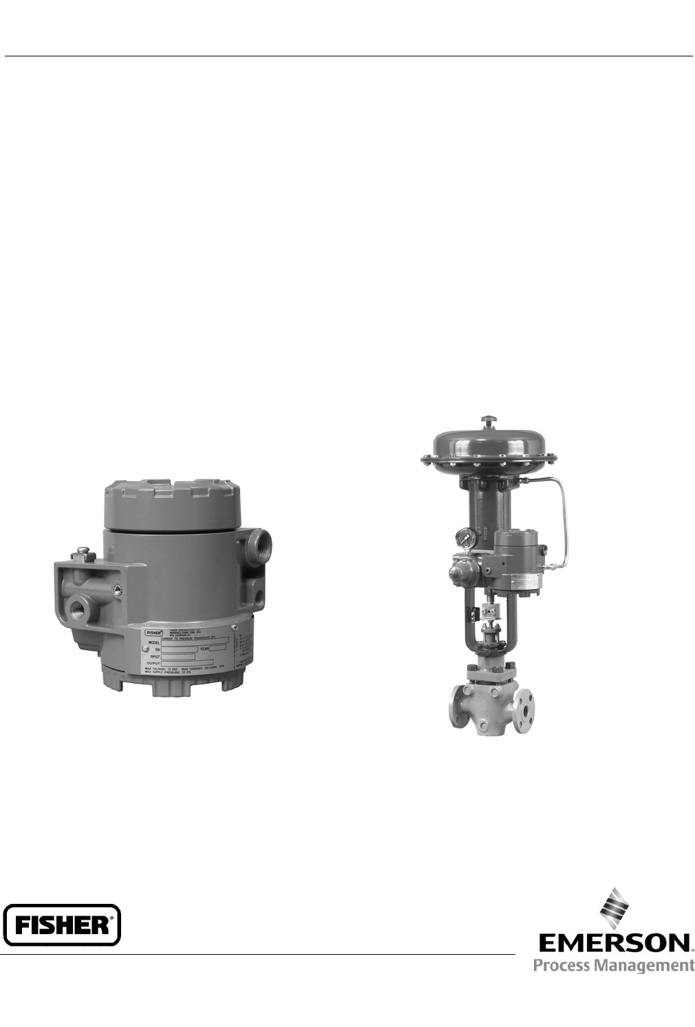
Fisherr 846 Electro-Pneumatic Transducer
The Fisher 846 electro-pneumatic transducer is a
rugged, field-mountable transducer that accepts an
electrical input signal and converts it to a pneumatic
output signal. Typically, the 4 to 20 mA is converted to
0.2 to 1.0 bar (3 to 15 psi). In the most common
application, the transducer converts an electrical
output signal from a controller to a pneumatic signal
necessary to operate a control valve actuator or
pneumatic positioner.
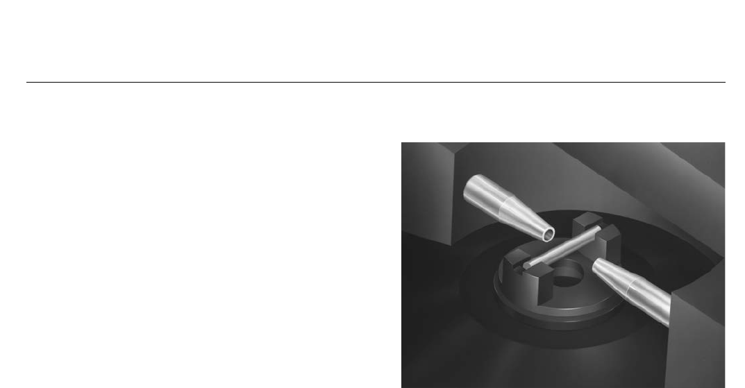
The transducer includes a deflector/nozzle design
(figure 1) that consists of two nozzles positioned so
that the constant air flow exiting the supply nozzle is
directed at the entrance of the receiver nozzle. Each
nozzle has a large bore of 0.41 mm (0.016 inches),
which provides good resistance to plugging. The input
current signal positions a deflector bar within the
nozzle's flow stream. As the input signal changes, the
deflector bar moves to alter the flow stream to the
receiver nozzle, establishing a pilot pressure at the
receiver nozzle. The pilot pressure, in turn, controls the
booster stage and output of the transducer.
An electronic feedback control network constantly
compares the value of the pneumatic output signal
with the input current signal. A solid-state pressure
sensor is part of the electronics package monitoring
the pneumatic output (figure 3). A comparator circuit
in the control network detects input-output deviations
and adjusts the output by moving the deflector in the
pilot stage to a corrected position. Because of this
feedback network, the transducer can correct for
error-producing effects such as variations in supply
pressure and downstream leakage.
X0234
W6307-1
846 MOUNTED
ON FISHER 667 ACTUATOR
FISHER 846 ELECTRO-
PNEUMATIC TRANSDUCER
846 Transducer
D102127X012
Product Bulletin
62.1:846
March 2015

846 Transducer
D102127X012
Product Bulletin
62.1:846
March 2015
2
Specifications
Input Signal
4-20 mA DC, field adjustable split ranging.
Equivalent Circuit
See figure 4
Output Signal
Standard Performance: J0.2 to 1.0 bar (3 to 15 psi).
Rangeability between 0.1 to 1.2 bar (1 and 18 psi)
Multirange Performance: J0 to 1.2 bar (0 to 18 psi),
J0.4 to 2.0 bar (6 to 30 psi), and J0 to 2.3 bar (0 to
33 psi) nominal ranges. Actual rangeability available
between 0.03 to 2.3 bar (0.5 and 33 psi)
Action: JDirect (increasing input signal increases
transducer output) (Minimum span, 6 psi) or
JReverse (increasing input signal decreases
transducer output) (Minimum span, 11 psi)
Supply Pressure
Standard Performance: 1.2 to 1.6 bar
(18 to 24 psi)
Multirange Performance:
Minimum: 0.2 bar (3 psi) [0.14 bar (2 psi) for a 2.3 bar
(33 psi) output] greater than the maximum calibrated
output pressure.
Maximum: 2.4 bar (35 psi)
Supply Pressure Medium
Clean, dry air
Per ISA Standard 7.0.01
A maximum 40 micrometer particle size in the air
system is acceptable. Further filtration down to 5
micrometer particle size is recommended. Lubricant
content is not to exceed 1 ppm weight (w/w) or
volume (v/v) basis. Condensation in the air supply
should be minimized.
Per ISO 8573-1
Maximum particle density size: Class 7
Oil content: Class 3
Pressure Dew Point: Class 3 or at least 10°C less than
the lowest ambient temperature expected
Maximum Steady-State Air Consumption(1)
0.3 m3/hr (12 scfh) at 1.4 bar (20 psi) supply pressure.
Output Air Capacity(1)
Standard Performance: 6.4 m3/hr (240 scfh) at
1.4 bar (20 psi) supply pressure.
Multirange Performance: 9.7 m3/hr (360 scfh) at
2.5 bar (35 psi) supply pressure
Temperature Limits
Operating: -40 to 85_C (-40 to 185_F)
Storage: -40 to 93_C (-40 to 200_F).
Humidity Limits
0-100% condensing relative humidity.
Performance(2)
Linearity, Hysteresis, and Repeatability: $0.3% of
span
Temperature Effect (total effect including zero and
span): $0.07%/_C (0.045%/_F) of span
Vibration Effect: $0.3% of span per g during the
following conditions:
5-15 Hz at 4 mm constant displacement
15-150 Hz at 2 g. 150-2000 Hz at 1 g.
per SAMA Standard PMC 31.1, Sec. 5.3, Condition 3,
Steady State.
Shock Effect: $0.5% of span, when tested per SAMA
Standard PMC 31.1, Sec. 5.4.
Supply Pressure Effect: Negligible
Electromagnetic Interference (EMI): Tested per IEC
61326-1 (Edition 1.1). Meets emission levels for Class
A equipment (industrial locations) and Class B
equipment (domestic locations). Meets immunity
requirements for industrial locations (Table A.1).
Immunity performance is shown in table 1.
Leak Sensitivity: Less than 1.0% of span for up to
4.8 m3/hr (180 scfh) downstream leakage.
Overpressure Effect: Less than 0.25% of span for
misapplication of up to 7.0 bar (100 psi) supply
pressure for less than 5 minutes to the input port.
Reverse Polarity Protection: No damage occurs from
reversal of normal supply current (4-20 mA) or from
misapplication of up to 100 mA.
Connections
Supply and Output Pressure: 1/4-18 NPT internal
connection.
Electrical: 1/2-14 NPT internal conduit connection.
- continued -
846 Transducer
D102127X012
Product Bulletin
62.1:846
March 2015
3
Specifications (Continued)
Adjustments
Zero and Span: Screwdriver adjustments located in
terminal compartment.
Remote Pressure Reading (optional)
ON or OFF; jumper selectable
Frequency Range: 0-10,000 Hz
Amplitude: 0.4-1.0 Vp-p
Required Operating Voltage
Min. 6.0 V (at 4 mA)
Max. 7.2 V (at 20 mA)
with Remote Pressure Reading ON
Min. 6.4 V (at 4 mA)
Max. 8.2 V (at 20 mA)
Electrical Classification(3)
Hazardous Area
(see Bulletin 9.2:001, D103222X012)
CSA C/US—Intrinsically Safe, Explosion-proof,
Non-Incendive
FM—Intrinsically Safe, Explosion-proof,
Non-Incendive
ATEX—Intrinsically Safe, Flameproof, Type n
IECEx—Intrinsically Safe, Flameproof
Electrical Housing
Tropicalization (Fungus test per MIL-STD-810)
CSA C/US—Type 4X
FM—Type 4X
ATEX—IP66(4)
IECEx—IP66(4)
Other Classifications/Certifications
CUTR— Customs Union Technical Regulations
(Russian, Kazakhstan, and Belarus)
INMETRO—National Institute of Metrology, Quality,
and Technology (Brazil)
KGS—Korea Gas Safety Corporation (South Korea)
NEPSI— National Supervision and Inspection Centre
for Explosion Protection and Safety of
Instrumentation (China)
Contact your Emerson Process Management
sales office for classification/certification
specific information
Construction Materials
Housing: JLow-copper aluminum with polyurethane
paint, or J CF8M
O-Rings: Nitrile, except silicone for sensor O-rings.
Mounting
JActuator, Jpipestand, or Jsurface
Weight
Aluminum: 2.9 kg (6.5 lb) excluding options
Stainless Steel: 6.7 kg (14.8 lb) excluding options
Options
JFisher 67CFR filter regulator, Jsupply and output
gauges, Jremote pressure reading, or Jstainless
steel mounting bracket
NOTE: Specialized instrument terms are defined in ANSI/ISA Standard 51.1 - Process Instrument Terminology
1. Normal m3/hr: normal cubic meters per hour (m3/hr, 0_C and 1.01325 bar, absolute). Scfm: standard cubic feet per minute (ft3/min, 60_F and 14.7 psig).
2. Performance values are obtained using a transducer with a 4 to 20 mA dc input signal, a 3 to 15 psig output, and 20 psig supply pressure.
3. Refer to tables 2, 3, 4, and 5 for additional information.
4. ATEX and IECEx Flameproof — IP66 per CSA Letter of Attestation.
Table 1. EMC Immunity Performance Criteria
Port Phenomenon Basic Standard Test Level Performance Criteria(1)
Enclosure
Electrostatic discharge
(ESD) IEC 61000-4-2 4 kV contact
8 kV air A
Radiated EM field IEC 61000-4-3
80 to 1000 MHz @ 10V/m with 1 kHz AM at 80%
1400 to 2000 MHz @ 3V/m with 1kHz AM at 80%
2000 to 2700 MHz @ 1V/m with 1kHz AM at 80%
A
I/O signal/control
Burst (fast transients) IEC 61000-4-4 1 kV A
Surge IEC 61000-4-5 1 kV (line to ground only, each) B
Conducted RF IEC 61000-4-6 150 kHz to 8 MHz at 3 Vrms B
8 MHz to 80 MHz at 3 Vrms A
Specification limit = ±1% of span
1. A = No degradation during testing. B = Temporary degradation during testing, but is self-recovering.
846 Transducer
D102127X012
Product Bulletin
62.1:846
March 2015
4
Features
n Vibration Resistant—The low-mass pilot stage,
mechanically damped deflector bar, and rugged
construction provide stable performance in
vibration.
n Large Diameter Nozzles—Large diameter nozzles,
free-flow pilot stage design, and large internal
pneumatic supply passages provide excellent
tolerance to reducing the effects of contaminant
buildup and erosion.
n Increased Accuracy, Reduced Sensitivity to Supply
Pressure Variations and Downstream Leakage—The
electronic feedback control network monitors the
pneumatic output signal, detects any input-output
deviations and corrects them. This provides very
high accuracy and allows the transducer to sense
changes in the final element condition and rapidly
optimize its air delivery.
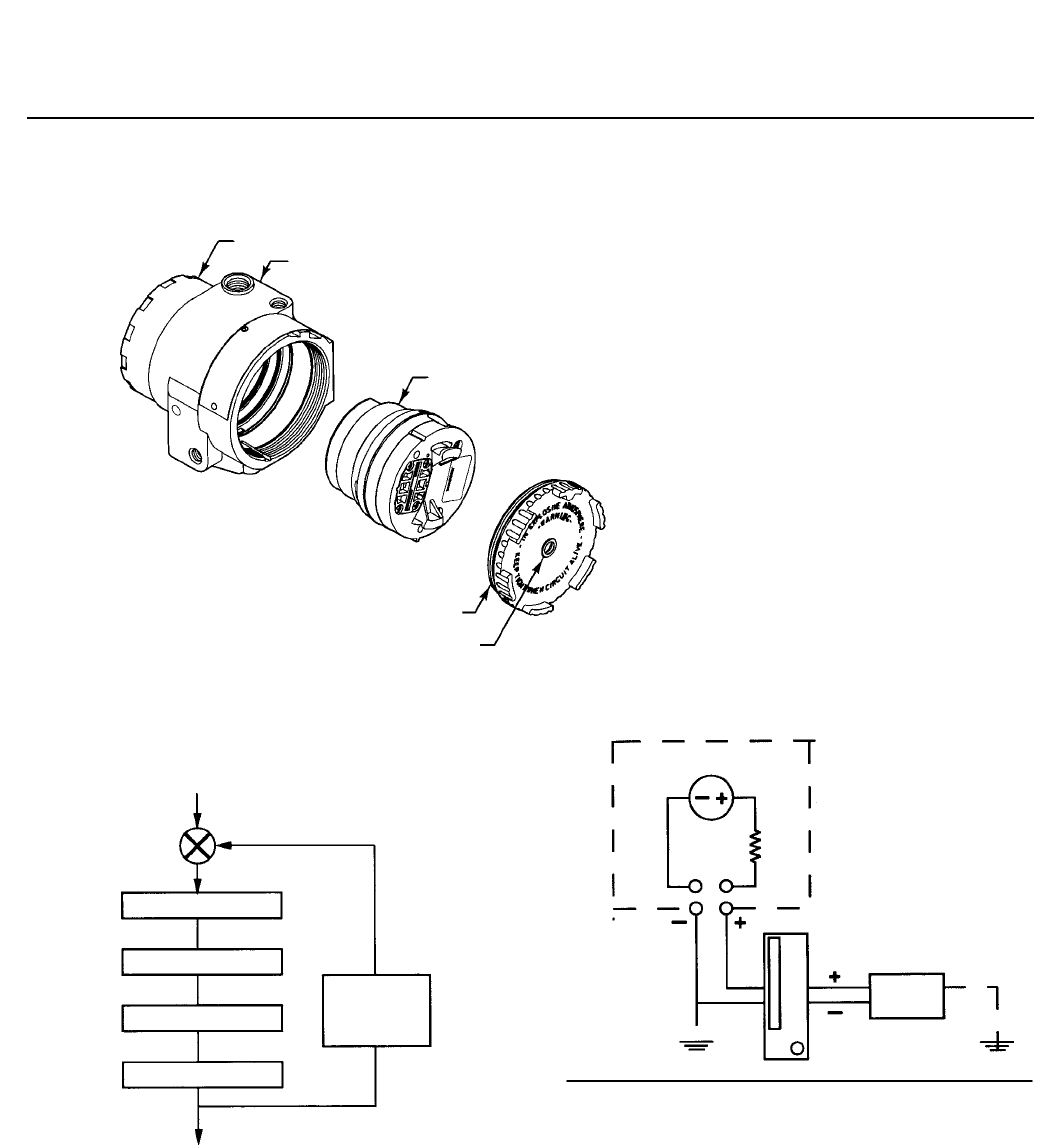
n Easy Maintenance—Major mechanical and electrical
components are incorporated into a single
field-replaceable “master module” (figure 2). The
transducer does not have to be removed from its
mounting to facilitate troubleshooting or service. A
separate field wiring compartment eases
installation and maintenance.
n Quick Diagnostic Checks and Remote Performance
Monitoring—With Stroke Port, a constant bleed from
the pilot stage vents through a hole in the module
cover. Covering the hole increases the transducer
output to confirm the proper operation of the pilot
and booster stages and stroke the actuator. With
optional Remote Pressure Reading, a frequency
directly proportional to the output pressure is
superimposed on the input signal wires.
Using a frequency counter, an operator can monitor
the 846 output pressure.
Figure 1. Detail of Deflector/Nozzle Pilot Stage
W6287
Installation
The transducer may be actuator, wall, panel, or
pipestand mounted. Dimensions are shown in
figures 6, 7, and 8.
Ordering Information
To determine what ordering information is required,
refer to the specification table. Carefully review the
description of each specification. Specify the desired
choice whenever there is a selection available.
When ordering mounting parts, specify actuator,
surface, or pipestand mounting. For actuator
mounting, specify the actuator type, size, travel, and
diaphragm pressure range. For all 657 and 667
actuators except size 80, specify whether actuator
yoke or actuator casing mounting is desired (yoke
mounting only is available on size 80 actuators).
846 Transducer
D102127X012
Product Bulletin
62.1:846
March 2015
5
Figure 2. Master Module Construction
A6326
TERMINAL COVER
TRANSDUCER HOUSING
MASTER MODULE
MODULE COVER
STROKE PORT
Figure 3. Functional Block Diagram
4 TO 20 mA
INPUT
ELECTRONIC CIRCUIT
MAGNETIC ACTUATOR
PILOT STAGE
BOOSTER STAGE
SOLID-STATE
PRESSURE
SENSOR
3 TO 15 PSI
OUTPUT, TYPICAL
A6324
Figure 4. Equivalent Circuit
Note:
The 846 is not a constant resistor in series with an inductor. It is better
modeled in the loop as a 50 ohm resistor in series with a 6 volt DC voltage drop
with negligible inductance.
A6325
846 TRANSDUCER
6 VDC
50
OHMS
POWER
SUPPLY
846 Transducer
D102127X012
Product Bulletin
62.1:846
March 2015
6
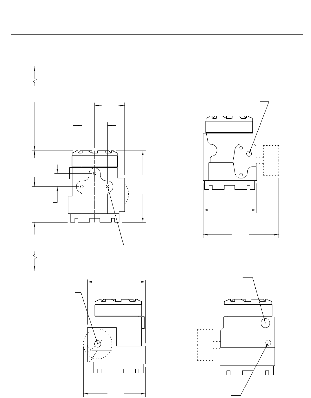
Figure 5. Dimensions
67
(2.62)
COVER REMOVAL
CLEARANCE
59
(2.31)
68
(2.69)
78
(3.08)
29
(1.13)
5/16-18
3 PLACES
137
(5.38)
MODULE COVER
REMOVAL CLEARANCE
156
(6.15)
119
(4.68)
1/4-18 NPT
SUPPLY CONN
168
(6.60)
129
(5.07)
1/4-18 NPT
OUTLET CONN
PLUGGED WHEN
GAUGE NOT
FURNISHED
5.43
(138)
1/2-14 NPT
CONDUIT CONN
1/4-18 NPT
OUTLET CONN mm
(INCH)
14B7364-C
846 Transducer
D102127X012
Product Bulletin
62.1:846
March 2015
7
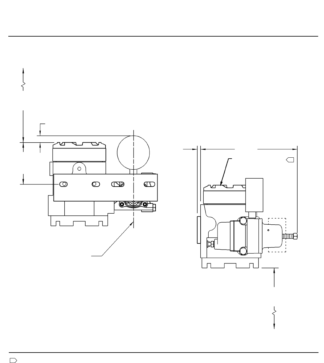
Figure 6. Dimensions with Optional Fisher 67CFR Filter-Regulator (Yoke Mounted)
FOR PROPER MOISTURE
DRAINAGE THIS END
MUST BE UP
67
(2.62) COVER REMOVAL
CLEARANCE
13
(0.50)
78
(3.08)
CENTERLINE OF ACTUATOR
6
(0.25)
191
(7.51)
YOKE MOUNTED
14B7361-D
mm
(INCH)
1
MODULE
COVER
REMOVAL
CLEARANCE
137
(5.38)
Note:
1 The mounting positions shown allow any moisture buildup in the terminal compartment to drain to the signal wire conduit
entrance. Do not mount the transducer with the terminal compartment cover on the bottom; moisture may accumulate in the
terminal compartment or pilot stage, preventing proper transducer operation. The vertical mount is most effective for moisture
drainage in wet applications.
846 Transducer
D102127X012
Product Bulletin
62.1:846
March 2015
8
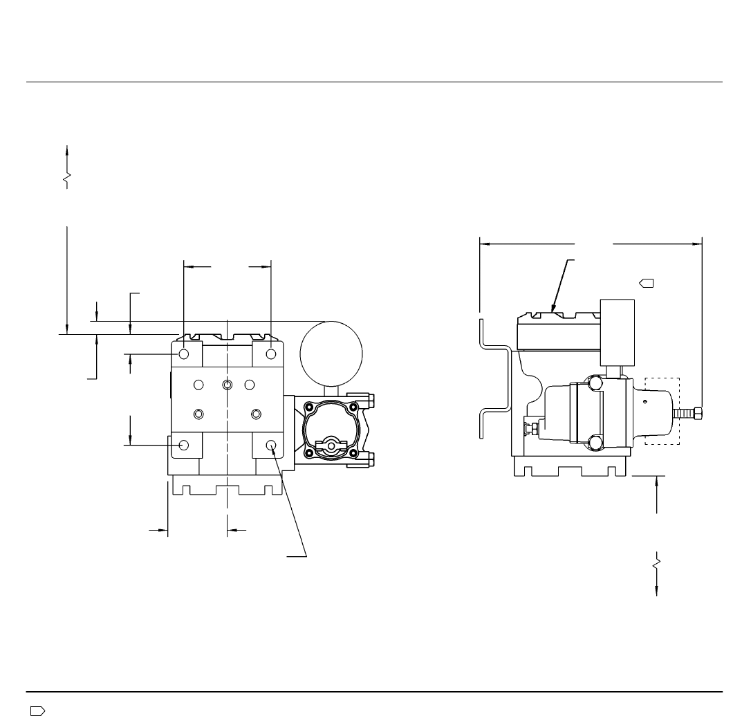
Figure 7. Dimensions with Optional Fisher 67CFR Filter-Regulator (Surface/Wall Mounted)
Note:
1 The mounting positions shown allow any moisture buildup in the terminal compartment to drain to the signal wire conduit
entrance. Do not mount the transducer with the terminal compartment cover on the bottom; moisture may accumulate in the
terminal compartment or pilot stage, preventing proper transducer operation. The vertical mount is most effective for moisture
drainage in wet applications.
FOR PROPER MOISTURE
DRAINAGE THIS END
MUST BE UP
10/0.38∅
MOUNTING
HOLE
4 PLACES
137
(5.38)
222
(8.76)
67
(2.62) COVER REMOVAL
CLEARANCE
89
(3.50)
19
(0.76)
89
(3.50)
13
(0.50)
61
(2.39) MODULE COVER
REMOVAL
CLEARANCE
14B7332-D
SURFACE/WALL MOUNTED
mm
(INCH)
1
846 Transducer
D102127X012
Product Bulletin
62.1:846
March 2015
9
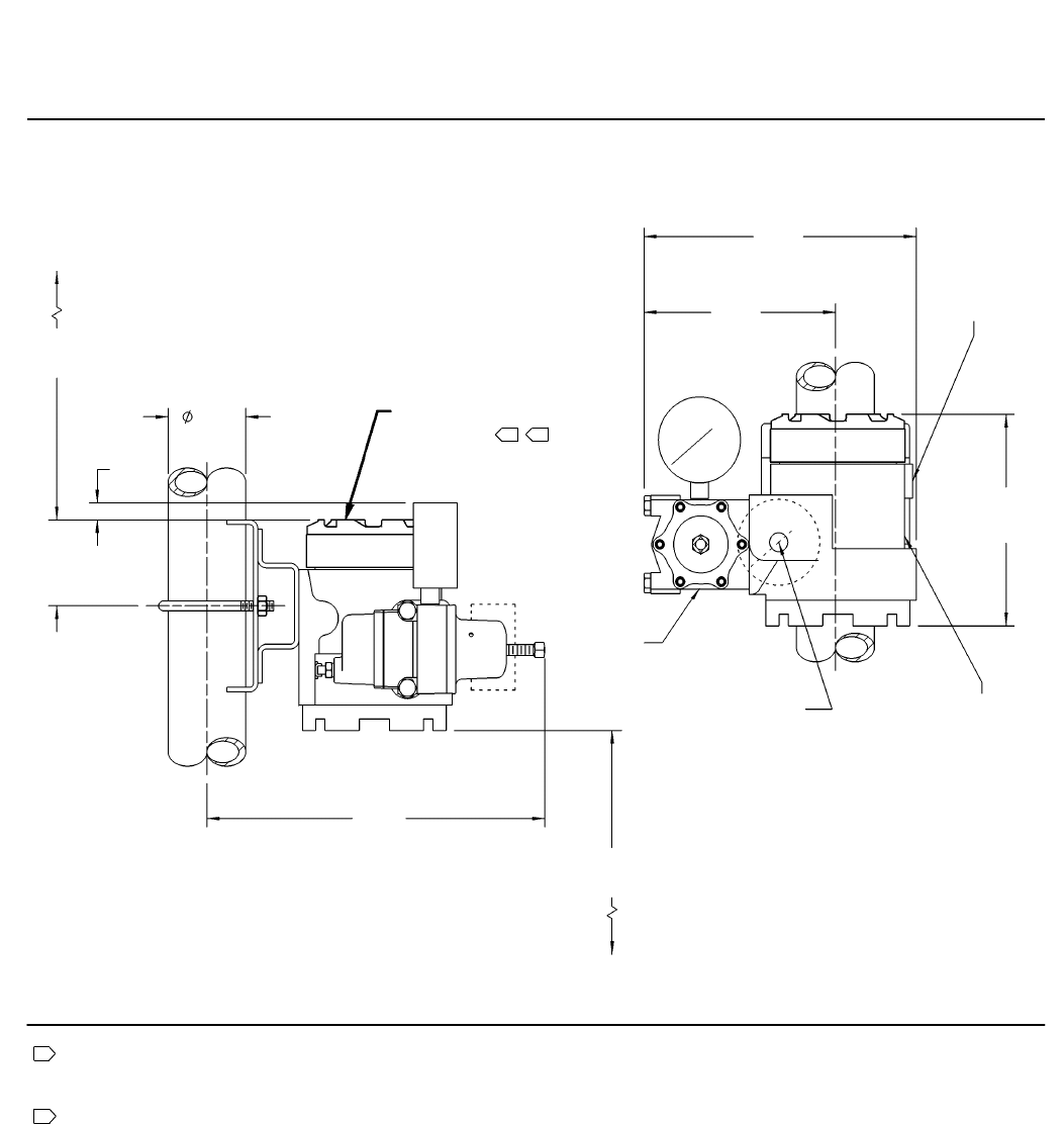
Figure 8. Dimensions with Optional Fisher 67CFR Filter-Regulator (Pipe Stand Mounted)
67
(2.62) COVER REMOVAL
CLEARANCE
54
(2.51)
MODULE
COVER
REMOVAL
CLEARANCE
FOR PROPER MOISTURE
DRAINAGE THIS END
MUST BE UP
14B7363-D
137
(5.38)
PIPE STAND MOUNTED
210
(8.27)
148
(5.82)
156
(6.15)
67CFR
1/4-18 NPT
SUPPLY CONN
mm
(INCH)
1
Notes:
1 The mounting positions shown allow any moisture buildup in the terminal compartment to drain to the signal wire conduit
entrance. Do not mount the transducer with the terminal compartment cover on the bottom; moisture may accumulate in the
terminal compartment or pilot stage, preventing proper transducer operation. The vertical mount is most effective for moisture
drainage in wet applications.
2 If mounted on horizontal pipe, the I/P must be on top of the pipe for proper moisture drainage.
2
60
(2.38)
13
(0.50)
262
(10.31)
1/2-14 NPT
CONDUIT CONN
1/2-14 NPT
CONDUIT CONN
1/2-14 NPT
OUTLET CONN
PLUGGED WHEN
GAUGE NOT
FINISHED

846 Transducer
D102127X012
Product Bulletin
62.1:846
March 2015
10
Table 2. Hazardous Area Classifications for Canada—cCSAus
Certification Body Certification Obtained Entity Rating Temperature Code
CSA
Ex ia Intrinsically Safe
Class I Division 1 Groups A,B,C,D T4
per drawing GE59146
Vmax = 30 VDC
Imax = 100 mA
Ci = 0.016 mF
Li = 20 mH
T4 (Tamb ≤ 60_C)
XP Explosion-proof
Class I Division 1 Groups C,D
DIP Dust Ignition-proof
Class II III Division I Groups E,F,G T4
NI Non-incendive
Class I, Division 2, Groups A,B,C,D T4
- - - T4 (Tamb ≤ 60_C)
Table 3. Hazardous Area Classification for United Stated—FM
Certification Body Certification Obtained Entity Rating Temperature Code
FM
IS Intrinsically Safe
Class I, II, III Division 1 Groups A,B,C,D,E,F,G
per drawing GE59147
Vmax = 30 VDC
Imax = 100 mA
Pmax = 1.0 W
Ci = 0.016 mF
Li = 20 mH
T4 (Tamb ≤ 60_C)
XP Explosion-proof
Class I Division 1 Groups B,C,D
DIP Dust Ignition-proof
Class II, III Division I Groups EFG
NI Non-incendive
Class I Division 2 Groups A,B,C,D
- - - T4 (Tamb ≤ 60_C)
Table 4. Hazardous Area Classifications—ATEX
Certificate Certification Obtained Entity Rating Temperature Code
ATEX
Intrinsically Safe
II 1 GD
Gas
Ex ia IIC T4,T5 Ga
Dust
Ex ia IIIC IP66 Da T90_C (Tamb ≤ 80_C)
Ex ia IIIC IP66 Da T50_C (Tamb ≤ 40_C)
Ui = 30 VDC
Ii = 100 mA
Pi = 1.0 W
Ci = 8 nF
Li = 20 mH
T4 (Tamb ≤ 80_C)
T5 (Tamb ≤ 40_C)
Flameproof
II 2 G
Gas
Ex d IIB T5/T6 Gb
- - - T5 (Tamb ≤ 80_C)
T6 (Tamb ≤ 65_C)
Type n
II 3 GD
Gas
Ex nA IIC T5/T6 Gc
Dust
Ex tc IIIC T88_C T500 Dc IP66
Ex tc IIIC T77_C T500 Dc IP66
- - - T5 (Tamb ≤ 85_C)
T6 (Tamb ≤ 74_C)

846 Transducer
D102127X012
Product Bulletin
62.1:846
March 2015
11
Table 5. Hazardous Area Classifications—IECEx
Certificate Certification Obtained Entity Rating Temperature Code
IECEx
Intrinsically Safe
Gas
Ex ia IIC T4/T5 Ga
Ui = 40 VDC
Ii = 200 mA
Pi = 1.0 W
Ci = 8 nF
Li = 20 mH
T4 (Tamb ≤ 80_C)
T5 (Tamb ≤ 40_C
Flameproof
Gas
Ex d IIB T5/T6 Gb
- - - T5 (Tamb ≤ 80_C)
T6 (Tamb ≤ 65_C)

846 Transducer
D102127X012
Product Bulletin
62.1:846
March 2015
12
Emerson Process Management
Marshalltown, Iowa 50158 USA
Sorocaba, 18087 Brazil
Chatham, Kent ME4 4QZ UK
Dubai, United Arab Emirates
Singapore 128461 Singapore
www.Fisher.com
The contents of this publication are presented for informational purposes only, and while every effort has been made to ensure their accuracy, they are not
to be construed as warranties or guarantees, express or implied, regarding the products or services described herein or their use or applicability. All sales are
governed by our terms and conditions, which are available upon request. We reserve the right to modify or improve the designs or specifications of such
products at any time without notice.
E 1995, 2015 Fisher Controls International LLC. All rights reserved.
Fisher is a mark owned by one of the companies in the Emerson Process Management business unit of Emerson Electric Co. Emerson Process Management,
Emerson, and the Emerson logo are trademarks and service marks of Emerson Electric Co. All other marks are the property of their respective owners.
Neither Emerson, Emerson Process Management, nor any of their affiliated entities assumes responsibility for the selection, use or maintenance
of any product. Responsibility for proper selection, use, and maintenance of any product remains solely with the purchaser and end user.
