Emerson Fisher 8580 Data Sheet
2015-03-30
: Emerson Emerson-Fisher-8580-Data-Sheet-680512 emerson-fisher-8580-data-sheet-680512 emerson pdf
Open the PDF directly: View PDF ![]() .
.
Page Count: 20
www.Fisher.com
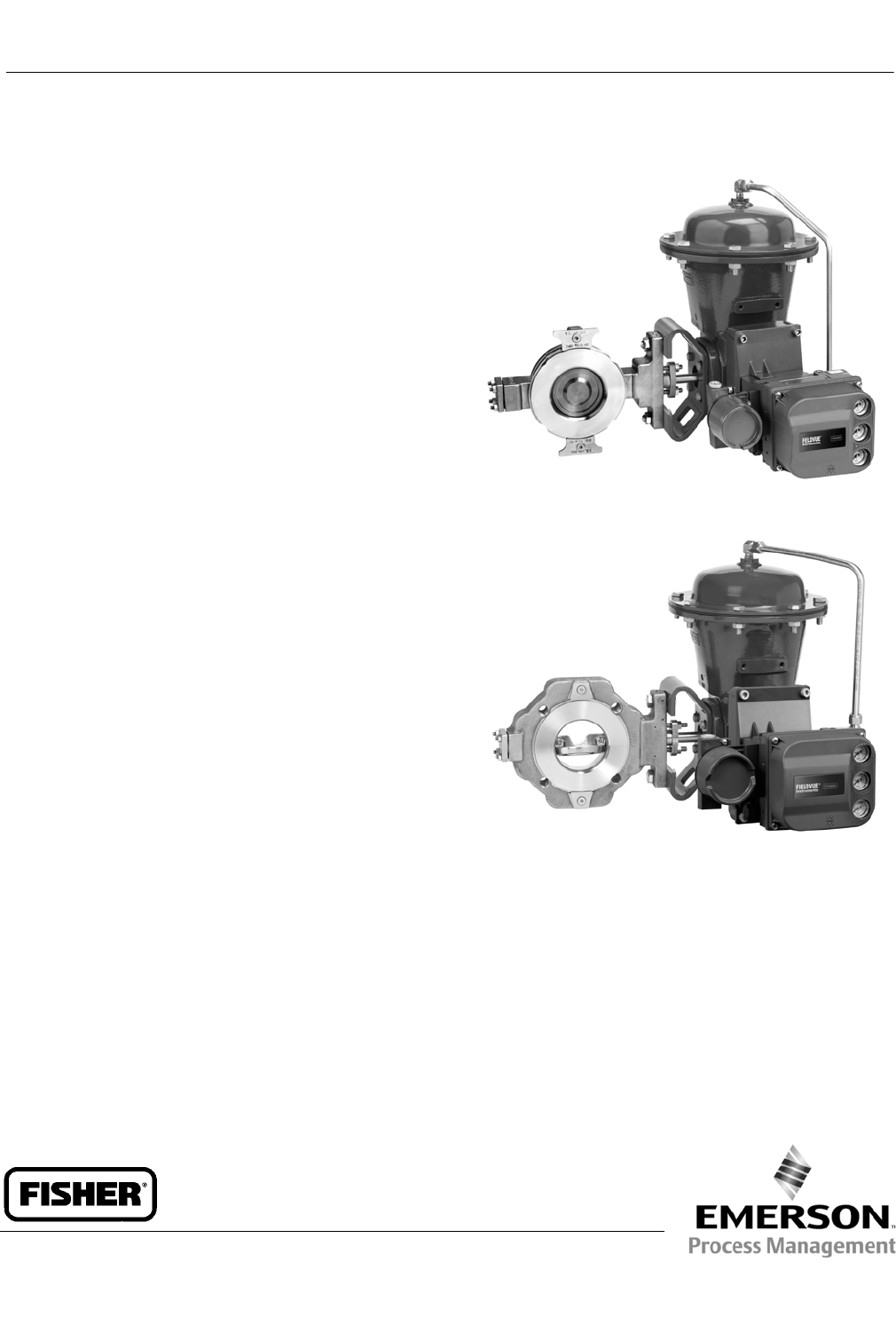
Fisherr8580 Rotary Valve
The Fisher 8580 rotary valve offers excellent throttling
performance. An approximately linear flow
characteristic provides precise throttling control. The
8580 valve offers high cycle life and rugged reliability.
The valve body meets PN 10 through PN 40, CL150,
and CL300 ratings. Face-to-face dimensions meet EN
558, API 609, and MSS-SP68 standards. Line centering
clips provide for versatility to mount and align the
same wafer style valve body in different piping
configurations (ASME and EN ratings).
The 8580 rotary valve features an eccentrically-
mounted disk with either soft or metal seal, providing
capability for enhanced shutoff. The interchangeable
sealing technology allows for the same valve body to
accept both soft and metal seals.
The actuator sizing and selection process is improved
by simply reading a table for information.
8580 Features
Approximately linear flow characteristic– An
approximately linear flow characteristic provides
precise throttling control.
Global Standards– The valve meets API, ASME, and
EN standards, making it suitable for use in all world
areas.
PEEK/PTFE bearing as standard– The PTFE-lined
PEEK bearing is a low friction, low wear bearing. It
allows the valve to operate under high pressure
drops for a high cycle life while maintaining low
torque. The “drop-in” bearing design enables fast,
easy maintenance.
Spline-ended Shaft– The splined shaft with clamped
lever and single-pivot linkage reduces lost motion
between the actuator and the valve shaft.
WAFER STYLE
W9425-2
SINGLE FLANGE STYLE
W9498-2
Improved shaft-disk pinning– The improved
expansion pin system ensures there is a positive,
durable connection between disk and shaft. This
connection reduces backlash and wear in the drive
system, optimizing long-term performance. It also
makes disassembly for maintenance quick and
simple with no need for special tools.
8580 Valve
D103299X012
Product Bulletin
51.6:8580
July 2012

8580 Valve
D103299X012
Product Bulletin
51.6:8580
July 2012
2
New Spring-Loaded Shaft– The spring in the
outboard shaft provides support to the drive train
and disk, enabling the shaft to be installed in both
horizontal and vertical orientations with no
detriment to performance or cycle life. This
complements the ability to mount the actuator on
the left-or right-hand side, enabling access for any
installation.
Excellent Emissions Capabilities– The optional
ENVIRO-SEALtpacking systems, are designed with
very smooth shaft surfaces and live-loading to
provide improved sealing, guiding, and loading
force transmission. The seal of the ENVIRO-SEAL
system can control emissions to below 100 ppm
(parts per million).
Sour Service Capability– Trim and bolting materials
are available for applications involving sour liquids
and gases. These constructions comply with NACE
MR0175-2002, MR0103, and MR0175 / ISO 15156.
Field-Reversible Valve Action– The actuator/valve
assembly action can be converted from
push-down-to-open to push-down-to-close, or vice
versa, without additional parts.
Easy Installation– Line-centering clips engage the
line flange bolts to simplify installation and provide
for centering of wafer-style valves in the pipeline.
End connections are compatible with EN and ASME
standards.
Excellent Shutoff– Both the metal and soft seal
rings have pressure-assisting sealing action that
ensures tight shutoff regardless of pressure drop.
Long Seal Life– The opening and closing path of the
eccentric disk minimizes disk contact with the seal
ring, thereby reducing seal wear, undue friction,
and seating torque requirements. See figure 2.
Reliable Flange Gasketing Surface– The seal
retainer screws and retention clips are outside the
gasket surface of the seal retainer. Spiral-wound or
flat-sheet gaskets can be installed between the
uninterrupted seal retainer face and the pipeline
flange.
Integral Shaft-to-Valve Body Bonding– Standard
valve construction includes conductive packing to
provide electrical bonding for hazardous area
applications.
Powder paint as standard– The Emerson Process
Managementtpowder paint finish offers an
excellent corrosion-resistant finish to all steel parts.
High Temperature Capability– The valve will
operate at elevated temperatures, with the
appropriate trim components.
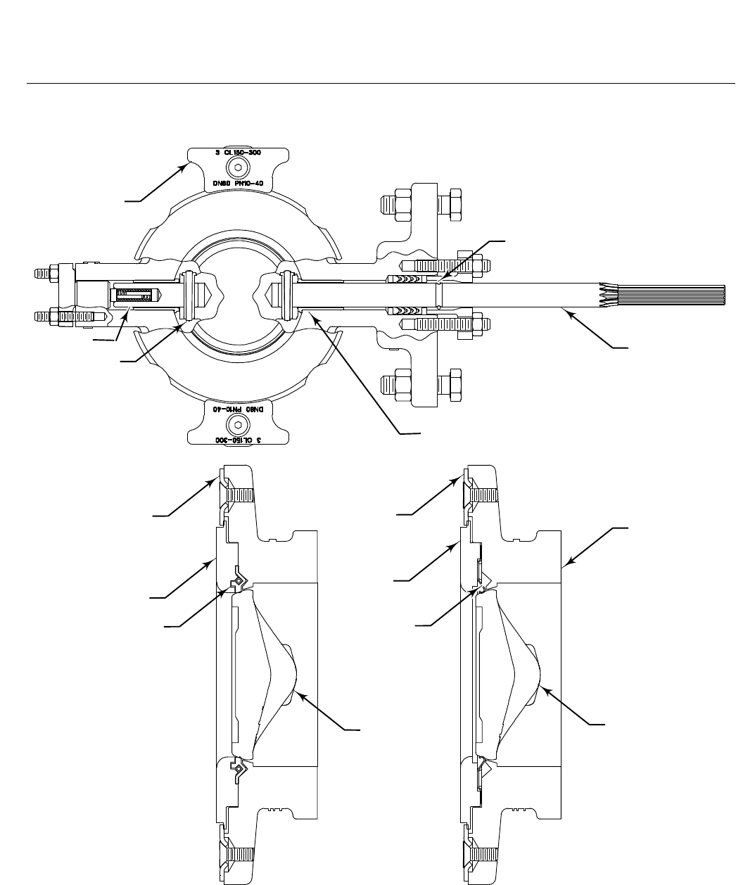
Shaft Retention– Redundant shaft retention
provides added protection. The packing follower,
anti-blowout ring, and shaft groove interact to hold
the shaft securely in the valve body (see figure 1).
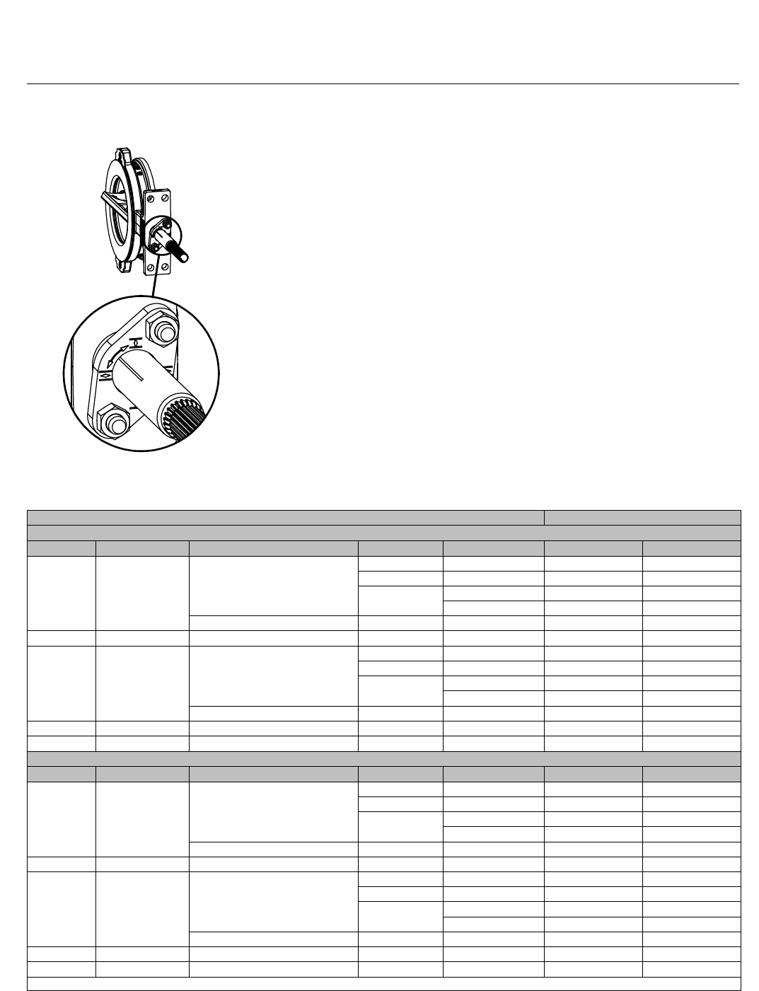
Travel Indication– Additional travel indication can
be achieved by using the indication line on the
shaft, along with the disk position markings on the
packing follower (see figure 4).
Table of Contents
8580 Features 1................................
8580 Valve Specifications and
Materials of Construction 3....................
2052 Actuator Specifications and
Materials of Construction 15...................
2052 Actuator Features 18.......................
8580 Valve
D103299X012
Product Bulletin
51.6:8580
July 2012
3
8580 Valve Specifications and Materials of Construction
Table 1. Fisher 8580 Valve Specifications
Specifications EN ASME
Valve Body Size DN 50, 80, 100, 150, 200, 250, and 300 NPS2,3,4,6,8,10,and12
Pressure Rating PN 10 to 40 per EN 12516-1CL150 / 300 per ASME B16.34
Valve Body Materials
EN 1.0619 steel WCC steel
EN 1.4409 stainless steel CF3M (316L) stainless steel
LCC LCC
CW2M(1) CW2M(1)
M35-2(2) M35-2
Disk Materials PTFE or RPTFE(4) Seal
EN 1.4409 stainless steel CF3M stainless steel
CW2M CW2M
M35-2 M35-2
Metal or UHMWPE(3) Seal Chrome-plated EN 1.4409 Stainless Steel Chrome-plated CF3M Stainless Steel
End Connections Mates with raised-face flanges per EN 1092-1Mates with raised-face flanges per ASME B16.5
Valve Body Style Wafer (flangeless) and single flange with tapped or through holes(5)
Face-to-Face Dimensions Meets MSS SP68, API 609, and EN 558 standards
Shutoff PTFE, RPTFE, or UHMWPE seal ring -Class VI per ANSI/FCI 70-2 and IEC 60534-4
S31600 (316 SST) seal ring -1% of Class IV per ANSI/FCI 70-2 and IEC 60534-4
Flow Coefficients See Fisher Catalog 12
Flow Direction Standard (forward flow) is with the seal retainer facing upstream; reverse flow is permissible for soft seals only
Flow Characteristic Approximately linear
Disk Rotation Counterclockwise to open (when viewed from actuator side of valve body) through 90 degrees of disk rotation
Shaft Diameters and Approximate Weights See table 8
1. This material is not listed in EN 12516-1orASMEB16.34.Seefigure6forpressure/temperatureratings.
2. This material is not listed in EN 12516-1.Seefigure6forpressure/temperatureratings.
3. UHMWPE stands for ultra high molecular weight polyethylene.
4. RPTFE is a reinforced PTFE seal.
5.LCCconstructionisstandardinwaferstyleonly.ConsultyourEmersonProcess Management sales office for single flange valve body style information.
Table 2. Materials (Other Valve Components)
Component Material
Shafts and Pins S17400 (17-4PH) stainless steel, S20910 (XM-19) stainless steel, N10276, N05500
Anti-blowout Ring N07718
Seal PTFE, RPTFE, or UHMWPE with S31600 (316 stainless steel) or R30003 spring. Metal seal is 316 stainless steel with
graphite gaskets
Bearings PEEK/PTFE, R30006 (Alloy 6), S31600 Nitride
Packing PTFE/carbon-filled PTFE (standard), graphite die-molded ribbon, ENVIRO-SEAL PTFE packing, ENVIRO-SEAL graphite
packing
Follower Spring N07718 with carbon-filled PEEK or S31600 spring seats
Bolting B8M Class 2, B7M, N05500, N07718
Nuts 8M, 2HM, N04400, N10276
Table 3. Trim Combinations with Standard Construction Materials
Valve Body Material Shaft Material Disk Material Bearings Seal Material
1.0619 & WCC S17400 H1075
1.4409 & CF3M PEEK/PTFE PTFE or RPTFE
1.4409 & CF3M Chrome-Plated PEEK/PTFE UHMWPE or Metal
Alloy 6 or S31600 Nitride Metal
LCC S17400 H1075 1.4409 & CF3M PEEK/PTFE PTFE
1.4409 & CF3M S20910
1.4409 & CF3M PEEK/PTFE PTFE or RPTFE
1.4409 & CF3M Chrome-Plated PEEK/PTFE UHMWPE or Metal
Alloy 6 or S31600 Nitride Metal
CW2M N10276 CW2M PEEK/PTFE PTFE or RPTFE
M35-2N05500 M35-2PEEK/PTFE PTFE or RPTFE
8580 Valve
D103299X012
Product Bulletin
51.6:8580
July 2012
4
Figure 1. Typical Fisher 8580 Valve Construction Detail
GE36289-ASOFT SEAL METAL SEAL
DISK
SEAL
RETAINER
RETAINER
CLIP VALVE BODY
SEAL RING
SEAL
RETAINER
RETAINER
CLIP
DISK
RETAINER CLIP (LINE
CENTERING CLIP)
DRIVE SHAFT
FOLLOWER
SHAFT
EXPANSION PIN
AND TAPER PIN
BEARING
ANTI-BLOWOUT
RING
SEAL RING

8580 Valve
D103299X012
Product Bulletin
51.6:8580
July 2012
5
Figure 2. Comparison of Disk Action
DISK FULLY CLOSED DISK FULLY OPEN
VALVE BODY
ECCENTRIC
DISK
CONVENTIONAL
DISK
OPEN
ECCENTRIC
DISK CENTER
OF ROTATION
CONVENTIONAL
DISK CENTER
OF ROTATION
CENTERLINE OF
VALVE BODY
SEAL RING (SOFT SEAL
CONSTRUCTION
SHOWN)
ECCENTRIC
DISK PATH
OF ROTATION
CONVENTIONAL
DISK PATH
OF ROTATION
GE36289-A
Figure 3. Available Seal Configuration
SOFT SEALS
SPRING
PRESSURE-
ASSISTED
SEAL
HIGH
PRESSURE
SHUTOFF
DISK FACE
VALVE
BODY
SEAL
RING
PRESSURE-ASSISTED
SEAL
HIGH
PRESSURE
SHUTOFF
DISK
FACE
VALVE BODY
B1558-3METAL SEAL
SEAL
RETAINER
SEAL
RETAINER
8580 Valve
D103299X012
Product Bulletin
51.6:8580
July 2012
6
Figure 4. Travel Indication
GE36289
Table 4. Material Temperature Capabilities
MATERIAL TEMPERATURE LIMITS
PN FLANGES
Valve Body Shaft Bearing Lining and Jacket Seal Packing _C_F
1.0619 Steel S17400 or S20910 PEEK / PTFE PTFE or RPTFE PTFE or Graphite —10 to 232 14 to 450
UHMWPE PTFE or Graphite —10 to 93 14 to 200
Metal PTFE —10 to 232 14 to 450
Graphite —10 to 260 14 to 500
R30006 (Alloy 6) or S31600 Nitride Metal Graphite —10 to 400(1) 14 to 752(1)
LCC S17400 or S20910 PEEK / PTFE PTFE PTFE —46 to 232 —50 to 450
1.4409
Stainless
Steel
S20910 PEEK / PTFE PTFE or RPTFE PTFE or Graphite —46 to 232 —50 to 450
UHMWPE PTFE or Graphite —18 to 93 0 to 200
Metal PTFE —46 to 232 —50 to 450
Graphite —46 to 260 —50 to 500
R30006 (Alloy 6) or S31600 Nitride Metal Graphite —10 to 500(1) 14 to 932(1)
CW2M N10276 PEEK / PTFE PTFE or RPTFE PTFE —10 to 232 14 to 450
M35-2N05500 PEEK / PTFE PTFE or RPTFE PTFE —10 to 232 14 to 450
ASME FLANGES
Valve Body Shaft Bearing Lining and Jacket Seal Packing _C_F
WCC steel S17400 or S20910 PEEK / PTFE PTFE or RPTFE PTFE or Graphite —29 to 232 -20 to 450
UHMWPE PTFE or Graphite —18 to 93 0 to 200
Metal PTFE —29 to 232 -20 to 450
Graphite —29 to 260 -20 to 500
R30006 (Alloy 6) or S31600 Nitride Metal Graphite —29 to 427(1) -20 to 800(1)
LCC S17400 or S20910 PEEK / PTFE PTFE PTFE —46 to 232 —50 to 450
CF3M
Stainless
Steel
S20910 PEEK / PTFE PTFE or RPTFE PTFE or Graphite —46 to 232 —50 to 450
UHMWPE PTFE or Graphite —18 to 93 0 to 200
Metal PTFE —46 to 232 —50 to 450
Graphite —46 to 260 —50 to 500
R30006 (Alloy 6) or S31600 Nitride Metal Graphite —46 to 454(1) —50 to 850(1)
CW2M N10276 PEEK / PTFE PTFE or RPTFE PTFE —46 to 232 —50 to 450
M35-2N05500 PEEK / PTFE PTFE or RPTFE PTFE —46 to 232 —50 to 450
1. For applications exceeding 316_C(600_F), consult your Emerson Process Management sales office for appropriate disk material selection.
8580 Valve
D103299X012
Product Bulletin
51.6:8580
July 2012
7
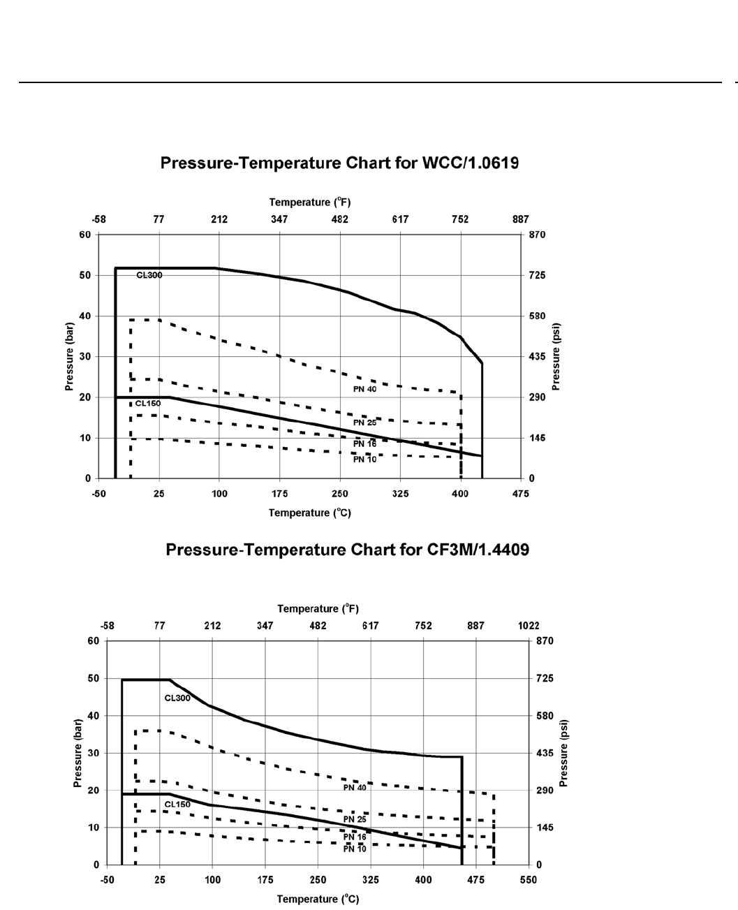
Figure 5. Material Pressure/Temperature Curves
8580 Valve
D103299X012
Product Bulletin
51.6:8580
July 2012
8
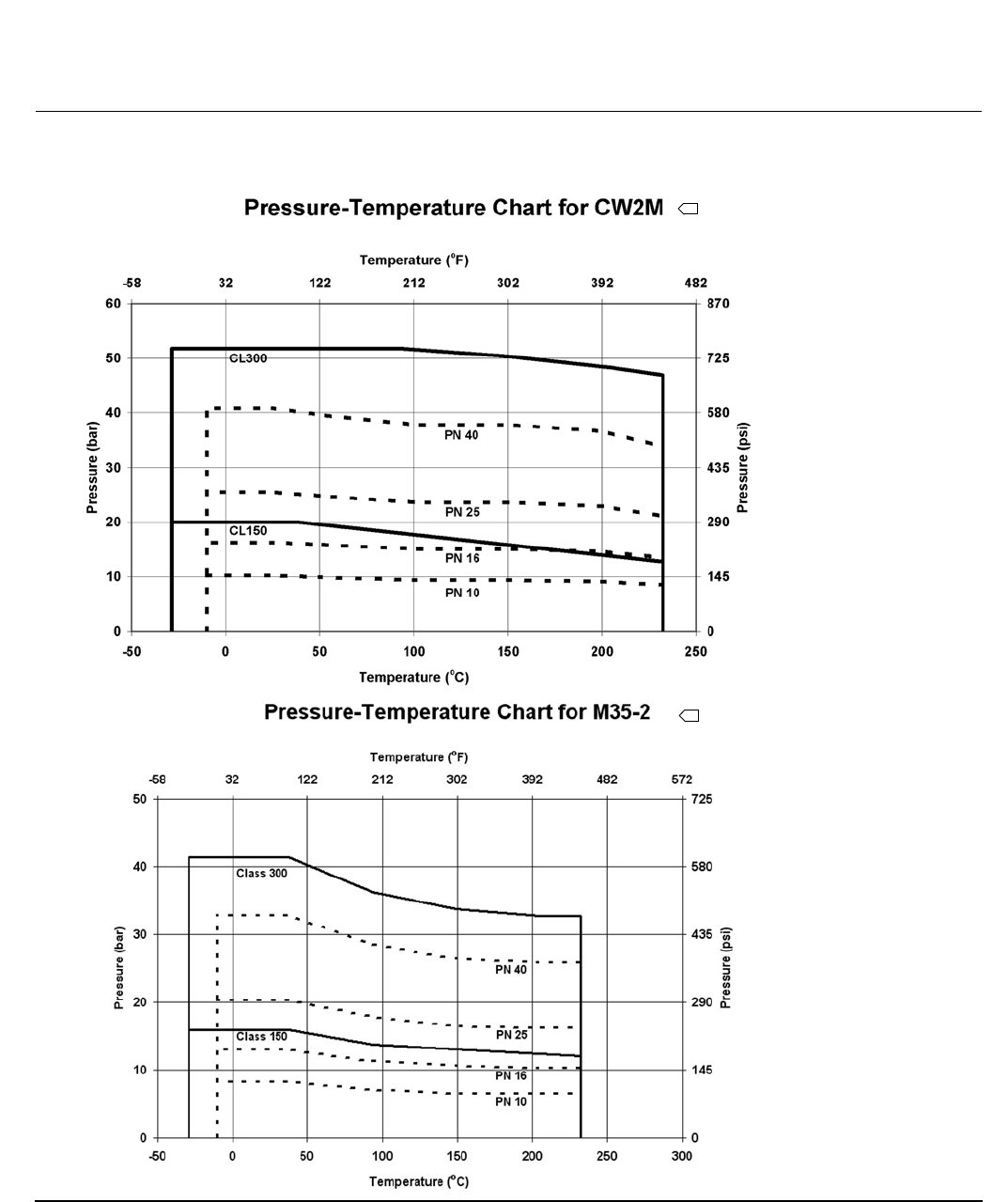
Figure 6. Material Pressure/Temperature Curves
1. CW2M is not listed in EN 12516-1 or ASME B16.34. The PN and CL designations are used only to indicate relative pressure-retaining capabilities.
2. M35-2 is not listed in EN 12516-1. The PN designations are used only to indicate relative pressure-retaining capabilities.
1
2
8580 Valve
D103299X012
Product Bulletin
51.6:8580
July 2012
9
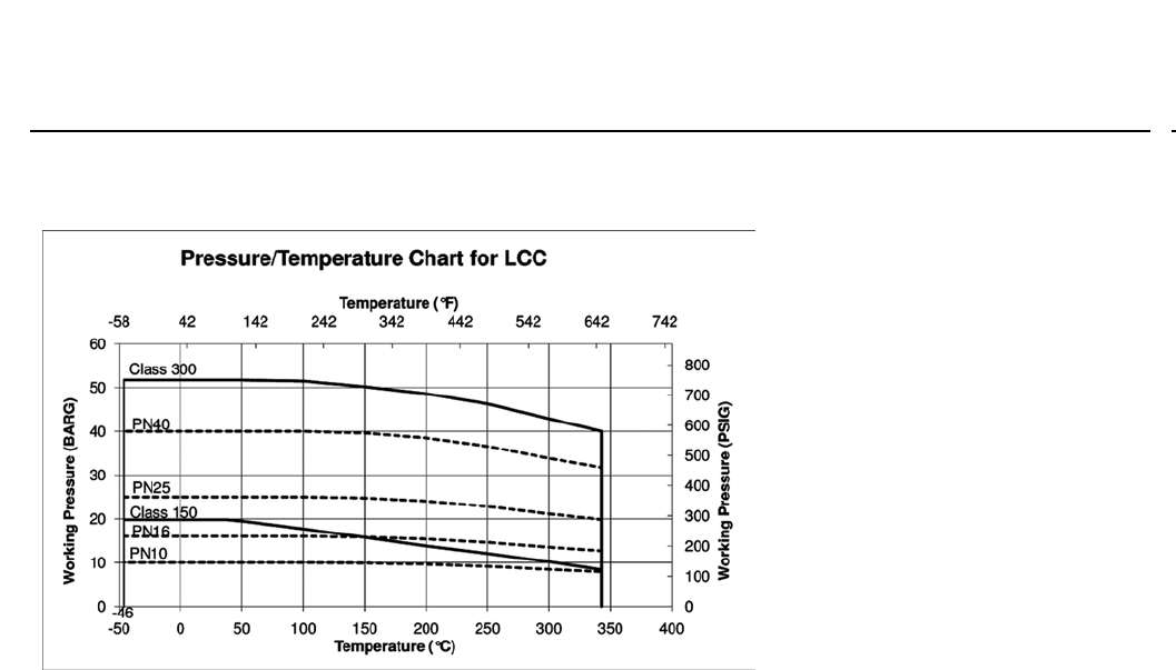
Figure 7. Material Pressure/Temperature Curves
E1140

8580 Valve
D103299X012
Product Bulletin
51.6:8580
July 2012
10
Table 5. Maximum Allowable Shutoff Pressure Drops based on Trim (Seal, Shaft, and Bearings), Bar
Note: Do not exceed the EN or ASME pressure/temperature rating of the valve or mating flanges.
TRIM TEMPERATURE, _C
DN
50 80 100 150 200 250 300
Bar
PTFE or RPTFE Seal
PEEK/PTFE Bearings
-46 to 65
93
121
149
191
204
232
51.7
48.5
38.6
28.7
13.8
10.3
3.4
51.7
48.5
38.6
28.7
13.8
10.3
3.4
51.7
48.5
38.6
28.7
13.8
10.3
3.4
51.7
48.5
38.6
28.7
13.8
10.3
3.4
51.7
48.5
38.6
28.7
13.8
10.3
3.4
35.2
35.0
33.8
28.7
13.8
10.3
3.4
41.4
38.8
35.7
28.7
13.8
10.3
3.4
UHMWPE Seal
PEEK/PTFE Bearings
-17 to 37
66
93
51.7
38.6
25.9
51.7
38.6
25.9
51.7
38.6
25.9
51.7
38.6
25.9
51.7
38.6
25.9
35.2
35.1
25.9
41.4
38.6
25.9
Metal Seal(1)
Alloy 6 Bearings
-46 to 37
93
149
204
260
316
371
427
454
18.5
17.0
16.0
15.1
14.3
13.8
13.2
12.5
12.1
16.5
15.1
14.2
13.4
12.8
12.3
11.9
11.6
11.5
13.9
12.8
12.0
11.4
10.8
10.3
10.0
9.8
9.7
12.8
11.7
11.0
10.4
9.9
9.5
9.2
9.0
8.9
11.0
10.1
9.4
9.0
8.5
8.2
7.9
7.7
7.7
6.8
6.3
5.9
5.6
5.3
5.1
5.0
4.8
4.8
7.0
6.5
6.1
5.7
5.4
5.2
5.0
5.0
4.9
Metal Seal(1)
S31600/Nitride Bearings
-46 to 37
93
149
204
260
316
371
427
454
19.5
19.3
17.0
15.9
14.5
13.8
13.2
12.5
12.1
28.2
28.0
25.4
24.3
22.9
22.1
21.5
20.7
20.3
26.1
26.0
23.7
22.7
21.4
20.8
20.2
19.5
19.2
20.8
20.6
18.7
17.8
16.8
16.2
15.7
15.2
14.9
31.0
31.0
28.8
26.3
24.6
23.2
22.4
21.8
21.6
15.5
15.4
14.0
13.3
12.5
12.1
11.8
11.4
11.2
8.0
7.9
7.1
6.8
6.3
6.1
5.9
5.6
5.4
Metal Seal(1)
PEEK/PTFE Bearings
-46 to 37
93
149
204
232
260
51.7
51.7
50.3
48.6
47.2
24.7
51.7
51.7
50.3
48.6
47.2
21.9
51.7
51.7
50.3
48.6
46.3
18.5
51.7
51.7
50.3
48.2
42.6
17.0
31.0
31.0
31.0
31.0
31.0
14.6
17.2
17.2
17.2
17.2
17.2
9.1
17.2
17.2
17.2
17.2
17.2
9.4
1. Pressure drops shown for metal seals are for forward flow only.

8580 Valve
D103299X012
Product Bulletin
51.6:8580
July 2012
11
Table 6. Maximum Allowable Shutoff Pressure Drops based on Trim (Seal, Shaft, and Bearings), Psi
Note: Do not exceed the EN or ASME pressure/temperature rating of the valve or mating flanges.
TRIM TEMPERATURE, _F
NPS
2 3 4 6 8 10 12
Psi
PTFE or RPTFE Seal
PEEK/PTFE Bearings
-50 to 150
200
250
300
375
400
450
750
704
560
416
200
150
50
750
704
560
416
200
150
50
750
704
560
416
200
150
50
750
704
560
416
200
150
50
750
704
560
416
200
150
50
511
508
490
416
200
150
50
600
563
518
416
200
150
50
UHMWPE Seal
PEEK/PTFE Bearings
0to100
150
200
750
560
375
750
560
375
750
560
375
750
560
375
750
560
375
511
509
375
600
560
375
Metal Seal(1)
Alloy 6 Bearings
-50 to 100
200
300
400
500
600
700
800
850
268
246
232
219
208
200
192
181
176
239
219
206
195
186
178
172
168
167
202
185
174
165
157
150
145
142
141
185
170
160
151
144
138
134
130
129
159
146
137
130
124
119
115
112
111
99
91
86
81
77
74
72
70
69
102
94
88
83
79
76
73
72
71
Metal Seal(1)
S31600/Nitride Bearings
-50 to 100
200
300
400
500
600
700
800
850
283
280
246
230
211
200
192
181
176
409
406
369
352
332
321
312
300
295
379
377
344
329
311
301
293
283
278
301
299
271
258
243
235
228
220
216
450
450
417
382
357
337
325
316
313
225
223
203
193
182
176
171
165
162
116
115
103
98
91
88
85
81
79
Metal Seal(1)
PEEK/PTFE Bearings
-50 to 100
200
300
400
450
500
750
750
730
705
685
358
750
750
730
705
685
318
750
750
730
705
672
269
750
750
730
699
618
247
450
450
450
450
450
212
250
250
250
250
250
132
250
250
250
250
250
136
1. Pressure drops shown for metal seals are for forward flow only.

8580 Valve
D103299X012
Product Bulletin
51.6:8580
July 2012
12
Table 7. Maximum Shutoff Pressure Drops with Soft Seal and PEEK/PTFE Bearings and Fisher 2052 Actuator
VALVE SIZE ACTUATOR SIZE MAXIMUM SHUTOFF PRESSURE DROP, BAR
DN 2 bar Operating Pressure 4 bar Operating Pressure
50
80
100
1
29.0
9.4
---
51.7
37.3
15.4
80
100
150
200
2
51.7
48.6
14.8
3.2
51.7
51.7
42.6
16.6
100
150
200
250
300
3(PDTO)
51.7
51.7
31.4
15.6
7.8
51.7
51.7
51.7
35.2
22.7
100
150
200
250
300
3(PDTC)
51.7
51.7
25.5
12.1
5.6
51.7
51.7
51.7
35.2
20.4
VALVE SIZE ACTUATOR SIZE MAXIMUM SHUTOFF PRESSURE DROP, PSIG
NPS 29 psig Operating Pressure 58 psig Operating Pressure
2
3
4
1
420
136
---
750
541
223
3
4
6
8
2
750
705
214
46.9
750
750
618
241
4
6
8
10
12
3(PDTO)
750
750
455
226
114
750
750
750
511
329
4
6
8
10
12
3(PDTC)
750
750
370
176
80.7
750
750
750
511
296

8580 Valve
D103299X012
Product Bulletin
51.6:8580
July 2012
13
Table 8. Dimensions and Weights
VALVE SIZE,
PRESSURE RATING
A E
F G
K R S(1) T U W
APPROXIMATE
WEIGHT(2)
Wafer Single
Flange Wafer Single
Flange Wafer Single
Flange
mm kg
DN50/
NPS 2
PN10-40/
CL150-
300
43 187.5 150 --- 109 --- 125 102 12.7 117 --- 14 4.7 6.7
DN80/
NPS 3
PN10-40/
CL150-
300
47/48
(3) 187.5 196 196 133 133 130 134 15.9 117 --- 14 7.5 11.2
DN100/
NPS 4
PN10-40/
CL150-
300
53 214.4 222 226 122 147 172 162 19.1 152 32 14 12.5 17.6
DN150/
NPS 6
PN10-40/
CL150-
300
57 214.4 270 300 147 182 205 218 25.4 152 32 14 15.7 26.5
DN200/
NPS 8
PN10-16/
CL150 61 208 327 342 225 225 258 271 31.8 235 46 18 30.2 40.2
PN25-40 61 208 358 364 225 225 258 285 31.8 235 46 18 33.9 46.0
CL300 73
DN250/
NPS 10
PN10-16/
CL150 69 208 390 395 218 250 270 324 31.8 235 46 18 38.9 50.5
PN25-40 69 208 400 450 265 265 270 345 31.8 235 46 18 51.8 79.2
CL300 83
DN300/
NPS 12
PN10-16/
CL150 78 208 381 467 309 309 304 381 38.1 235 46 18 68.7 98.3
PN25-40 78 208 410 512 309 309 304 410 38.1 235 46 18 76.6 104.6
CL300 92
Inches lbs
DN50/
NPS 2
PN10-40/
CL150-
300
1.69 7.38 5.91 --- 4.29 --- 4.92 4.02 0.50 4.62 --- 0.55 10 15
DN80/
NPS 3
PN10-40/
CL150-
300
1.85/
1.89
(3)
7.38 7.72 7.72 5.24 5.24 5.12 5.28 0.63 4.62 --- 0.55 17 25
DN100/
NPS 4
PN10-40/
CL150-
300
2.09 8.44 8.74 8.90 4.80 5.79 6.77 6.38 0.75 6.00 1.25 0.55 28 39
DN150/
NPS 6
PN10-40/
CL150-
300
2.24 8.44 10.63 11.81 5.79 7.17 8.07 8.58 1.00 6.00 1.25 0.55 35 58
DN200/
NPS 8
PN10-16/
CL150 2.40 8.19 12.87 13.46 8.86 8.86 10.16 10.67 1.25 9.25 1.81 0.71 67 89
PN25-40 2.40 8.19 14.09 14.33 8.86 8.86 10.16 11.22 1.25 9.25 1.81 0.71 75 102
CL300 2.87
DN250/
NPS 10
PN10-16/
CL150 2.72 8.19 15.35 15.55 8.58 9.84 10.63 12.76 1.25 9.25 1.81 0.71 86 111
PN25-40 2.72 8.19 15.75 17.72 10.43 10.43 10.63 13.58 1.25 9.25 1.81 0.71 114 175
CL300 3.27
DN300/
NPS 12
PN10-16/
CL150 3.07 8.19 15.00 18.39 12.17 12.17 11.97 15.00 1.50 9.25 1.81 0.71 151 217
PN25-40 3.07 8.19 16.14 20.16 12.17 12.17 11.97 16.14 1.50 9.25 1.81 0.71 169 231
CL300 3.62
1. This nominal valve shaft diameter is the shaft diameter through the packing box. Use this diameter when selecting Fisher actuators.
2. Valve assembly only.
3. 48 mm for CL150 and CL300 single flange only.
8580 Valve
D103299X012
Product Bulletin
51.6:8580
July 2012
14
Table9.LineBoltingDimensions
VALVE SIZE
Y
Pressure Rating
CL150 CL300 PN10 PN16 PN25 PN40
DN80 / NPS 3 4X 5/8-11 8X 3/4-10 8X M20X2.5
DN100 / NPS 4 8X 5/8-11 8X 3/4-10 8X M16X2 8X M20X2.5
DN150 / NPS 6 8X 3/4-10 12X 3/4-10 8X M20X2.5 8X M24X3(1)
DN200 / NPS 8 8X 3/4-10 12X 7/8-98X M20X2.5 12X M20X2.5 12X M24X3 12X M27X3(1)
DN250 / NPS 10 12X 7/8-916X 1-812X M20X2.5 12X M24X3 12X M27X3 12X M30X3.5(1)
DN300 / NPS 12 12X 7/8-916X 1-1/8-812X M20X2.5 12X M24X3 16X M27X3 16X M30X3.5
1. Not available in single flange with threaded holes.
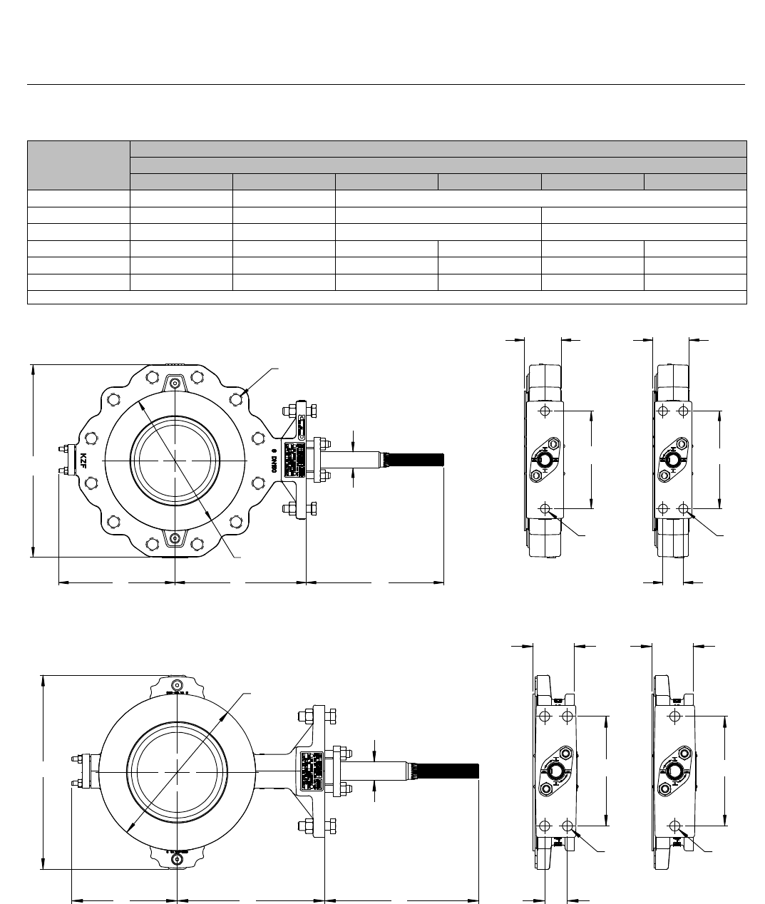
Figure 8. Dimensions for Fisher 8580, Single Flange Valve
A
A
TT
WW
U
R
S
F
GK E
Y
Figure 9. Dimensions for Fisher 8580, Wafer Style Valve AA
U
W
TT
W
S
EKG
R
F

8580 Valve
D103299X012
Product Bulletin
51.6:8580
July 2012
15
2052 Actuator Specifications and Materials of
Construction
Table 10. Fisher 2052 Actuator Specifications
Specifications
Actuator Mounting Connections Splined shaft connection, ISO 5211 actuator-to-bracket connection
Size 1: F07, Size 2: F10, Size 3: F14
Actuator Sizes See bulletin 61.1:2052
Operating Pressure(1) See bulletin 61.1:2052
Maximum Diaphragm Casing Pressure Size 1, 2, and 3 Actuators: 5 barg (73 psig)
Pressure Connection See bulletin 61.1:2052
Torque Output See bulletin 61.1:2052
Actuator Temperature Capabilities(1) -46 to 80_C (-50 to 176_F)
Operation Field reversible between PDTC and PDTO; right-and left-hand mounting, any angle of orientation
Approximate Weight
Size 1: 22.2 kg (49 lb)
Size 2: 54.4 kg (120 lb)
Size 3: 113 kg (250 lb)
Controller/Positioners Available DVC2000, DVC6200, 3610J, 3620J, 4190, C1
Accessories Available 846, 646, 2625, and 67C Series, switches, i2P-100, VBL, DXP, GOt
Handwheel Top-mounted handwheel: Optional on Size 1 and 2 actuators only
Declutchable handwheel: Optional on Size 1, 2, and 3 actuators
Operational Lockout Available for customer-supplied padlock to lock the actuator in the spring-fail position
1. The pressure/temperature limits in this bulletin and any applicable standard or code limitation for valve should not be exceeded.
Table 11. Materials of Construction
Component Material
Top Casing Steel
Housing Cast Iron
Diaphragm Nitrile and nylon standard
Lever Ductile iron
Diaphragm Plate Cast iron
OPTIONAL TOP-MOUNTED HANDWHEEL ASSEMBLY
Component Material
Handwheel Cast iron
Handwheel Stem Aluminum-Bronze
Top Casing Assembly Steel
O-ring Nitrile
Pusher Plate Steel

8580 Valve
D103299X012
Product Bulletin
51.6:8580
July 2012
16
Table 12. Fisher 8580 Valve Breakout Torque Requirements
TRIM CONFIGURATION: SOFT SEAL WITH PEEK/PTFE BEARINGS
VALVE
SIZE SHAFT DIA
TORQUE, NSm
Shutoff nPmax
DN mm 3bar 7bar 10 bar 15 bar 20 bar 25 bar 35 bar 45 bar 50 bar
50 12.7 12.8 14.7 16.2 18.7 21.1 23.6 28.5 33.4 35.9
80 15.9 19.7 23.4 26.1 30.7 35.3 39.9 49.1 58.2 62.8
100 19.1 31.1 37.6 42.4 50.5 58.7 66.8 83.0 99.2 107
150 25.4 60.8 75.9 87.2 106 125 144 181 219 238
200 31.8 103 135 158 198 237 276 355 434 473
250 31.8 159 212 252 318 385 451 584 --- ---
300 38.1 228 310 371 473 576 678 883 --- ---
VALVE
SIZE SHAFT DIA
TORQUE, LbfSin
Shutoff nPmax
NPS Inch 50 psid 100 psid 150 psid 200 psid 300 psid 400 psid 500 psid 600 psid 750 psid
21/2 115 130 145 160 190 220 250 280 325
35/8 178 206 234 262 318 374 430 486 570
43/4 282 331 381 430 529 628 727 826 975
6 1 553 668 783 900 1130 1360 1590 1820 2160
8 1-1/4 945 1190 1430 1670 2150 2630 3110 3590 4310
10 1-1/4 1460 1870 2270 2680 3490 4300 5110 --- ---
12 1-1/2 2100 2720 3350 3970 5220 6470 7720 8970 ---
TRIM CONFIGURATION: METAL SEAL WITH METAL BEARINGS
VALVE
SIZE SHAFT DIA
TORQUE, NSm
Shutoff nPmax
DN mm 3bar 7bar 10 bar 15 bar 20 bar 25 bar 35 bar 45 bar 50 bar
50 12.7 37.3 42.4 46.2 52.5 --- --- --- --- ---
80 15.9 67.7 78.9 87.3 101 115 129 --- --- ---
100 19.1 112 134 151 178 206 233 --- --- ---
150 25.4 241 292 331 395 458 --- --- --- ---
200 31.8 310 422 506 646 786 927 --- --- ---
250 31.8 598 761 884 1090 --- --- --- --- ---
300 38.1 926 1270 --- --- --- --- --- --- ---
VALVE
SIZE SHAFT DIA
TORQUE, LbfSin
Shutoff nPmax
NPS Inch 50 psid 100 psid 150 psid 200 psid 300 psid 400 psid 500 psid 600 psid 750 psid
21/2 336 374 413 451 --- --- --- --- ---
35/8 611 696 782 867 1040 1210 --- --- ---
43/4 1020 1180 1350 1520 1850 --- --- --- ---
6 1 2190 2580 2970 3360 4140 --- --- --- ---
8 1-1/4 2860 3710 4570 5420 7130 8840 --- --- ---
10 1-1/4 5450 6700 7950 9200 --- --- --- --- ---
12 1-1/2 8540 11200 --- --- --- --- --- --- ---
8580 Valve
D103299X012
Product Bulletin
51.6:8580
July 2012
17
Table 13. Fisher 2052 Preferred Actuator Based On Actuator Torque Output
TRIM CONFIGURATION: SOFT SEAL WITH PEEK/PTFE BEARINGS
VALVE
SIZE SHAFT DIA nPmax
DN mm 3bar 7bar 10 bar 15 bar 20 bar 25 bar 35 bar 45 bar 50 bar
50 12.7 Size 1
80 15.9 Size 1 Size 2
100 19.1 Size 1 Size 2
150 25.4 Size 2 Size 3
200 31.8 Size 2 Size 3
250 31.8 Size 2 Size 3 NA
300 38.1 Size 3 NA
VALVE
SIZE SHAFT DIA nPmax
NPS Inch 50 psid 100 psid 150 psid 200 psid 300 psid 400 psid 500 psid 600 psid 750 psid
21/2 Size 1
35/8 Size 1 Size 2
43/4 Size 1 Size 2
6 1 Size 2 Size 3
8 1-1/4 Size 2 Size 3
10 1-1/4 Size 2 Size 3 NA
12 1-1/2 Size 3 NA
TRIM CONFIGURATION: METAL SEAL WITH METAL BEARINGS
VALVE
SIZE SHAFT DIA nPmax
DN mm 3bar 7bar 10 bar 15 bar 20 bar 25 bar 35 bar 45 bar 50 bar
50 12.7 Size 1 Size 2 NA
80 15.9 Size 2 NA
100 19.1 Size 2 Size 3 NA
150 25.4 Size 3 NA
200 31.8 Size 3 NA
250 31.8 Size 3 NA
300 38.1 NA
VALVE
SIZE SHAFT DIA nPmax
NPS Inch 50 psid 100 psid 150 psid 200 psid 300 psid 400 psid 500 psid 600 psid 750 psid
21/2 Size 1 Size 2 NA
35/8 Size 2 NA
43/4 Size 2 NA
6 1 Size 3 NA
8 1-1/4 Size 3 NA
10 1-1/4 Size 3 NA
12 1-1/2 NA

8580 Valve
D103299X012
Product Bulletin
51.6:8580
July 2012
18
2052 Actuator Features
Compact design, smaller actuators– Ensures
reduced valve/actuator envelope dimensions
leading to greater mounting versatility for both
skidsandprocessplants,wherespaceisata
premium.
Compatible with DVC6200 and DVC2000 digital
valve controllers; and 3610J and 3620J positioners–
The new actuator allows linkage-less feedback via a
contact-less magnetic array, from the lever to the
window-mounted DVC6200 or end-mounted
DVC2000. Integral window mounting of the 3610J
and 3620J is also available.
Clamped lever to reduce lost motion– The
clamping of the lever onto a splined valve shaft,
coupled with the single pivot linkage, reduces lost
motion between the actuator and the valve. The
typical cumulative deadband for a Fisher rotary
control valve assembly results in 0.5% or less
variability.
No bench set required– The new nested spring
design requires no bench set. This also simplifies the
actuator selection process, see bulletin 61.1:2052,
D103295X012.
ISO5211mountingwithoptionalinsert–The
actuator can now be mounted directly onto
non-spline shafts, such as Square and Double D. This
allows the actuator, with its enhanced control, to
mount on a wider range of valves conforming to ISO
5211.
Adjustable travel stops standard with optional
lockout feature– Provides the ability to adjust or
change the travel range without removing the
actuator or the addition of extra parts. The optional
lockout feature locks the lever in the spring-fail
position.
Fail-safe mechanism contains no aluminum– All
parts in the fail-safe mechanism (made of steel, cast
iron, and ductile iron) ensure the actuator will
maintain safety integrity in the event of a fire.
Powder paint as standard– The Emerson Process
Management powder paint finish offers an excellent
corrosion-resistant finish to all external steel and
cast iron parts.
NAMUR VDE/VDI 3845 for accessory mounting–
Meeting the global standard ensures compatibility
for most accessories, enabling quick and easy
mounting.
Field reversible, right-or left-hand mounting– The
actuator/valve assembly action can be converted
from push-down-to-open to push-down-to-close, or
vice-versa, without additional parts.
Declutchable and top-mounted handwheels–
Available (except top-mounted not available for size
3actuator).

8580 Valve
D103299X012
Product Bulletin
51.6:8580
July 2012
19
Options
Top-Mounted Handwheel: For infrequent use as a
manual actuator (see bulletin 61.1:2052,
D103295X012). For repeated or daily manual
operation, the unit should be equipped with a
declutchable handwheel actuator.
Declutchable Handwheel Actuator: An end-mounted
manual actuator can be used to provide on-site control
and to provide override capabilities. See bulletin
61.8:1078 for handwheel actuator specifications.
Limit Switches: JMicro-Switch or NAMCO switches
for one or two single-pole, double-throw contacts, or
JGO proximity switches for one or two single-pole,
double-throw contacts are available. See separate
bulletins for limit switch information.
Position Indicating Switch: TopWorxtDXP M21GNEB
switch for one through six single pole, double throw
switch contacts are available. See separate bulletin for
position indicating switch information.
Positioner: For precise positioning of the valve control
element, the actuator should be equipped with a
positioner. For additional information, contact your
Emerson Process Management sales office with
complete service conditions.
Actuator Locking Mechanism: An actuator locking
mechanism is available, which can be used to keep the
actuator in a locked position (the same as the
spring-fail position) during maintenance. The padlock
is customer supplied.

8580 Valve
D103299X012
Product Bulletin
51.6:8580
July 2012
20
Emerson Process Management
Marshalltown, Iowa 50158 USA
Sorocaba, 18087 Brazil
Chatham, Kent ME4 4QZ UK
Dubai, United Arab Emirates
Singapore 128461 Singapore
www.Fisher.com
The contents of this publication are presented for informational purposes only, and while every effort has been made to ensure their accuracy, they arenot
to be construed as warranties or guarantees, express or implied, regarding the products or services described herein or their use or applicability. All sales are
governed by our terms and conditions, which are available upon request. We reserve the right to modify or improve the designs or specifications of such
products at any time without notice.
E2008, 2012 Fisher Controls International LLC. All rights reserved.
Fisher,ENVIRO-SEAL,GO,andTopWorxaremarksowned by one of the companies in the Emerson Process Management business unit of Emerson Electric
Co. Emerson Process Management, Emerson, and the Emerson logo are trademarks and service marks of Emerson Electric Co. All other marks are the
property of their respective owners.
Neither Emerson, Emerson Process Management, nor any of their affiliated entities assumes responsibility for the selection, use or maintenance
of any product. Responsibility for proper selection, use, and maintenance of any product remains solely with the purchaser and end user.
