Emerson Fisher D4 Instruction Manual
2015-03-30
: Emerson Emerson-Fisher-D4-Instruction-Manual-680677 emerson-fisher-d4-instruction-manual-680677 emerson pdf
Open the PDF directly: View PDF ![]() .
.
Page Count: 24
www.Fisher.com
FisherrD4 Control Valve Assembly
Contents
Introduction 1.................................
Scope of Manual 1.............................
Description 1.................................
Specifications 2...............................
Educational Services 2.........................
Installation 4..................................
Spring Adjustment 5............................
Maintenance 6.................................
Valve Plug and Seat Ring 6......................
Valve Packing 8...............................
Actuator 10..................................
Parts Ordering 14...............................
Repair Kits 17..................................
Parts List 17...................................
Appendix A 19.................................
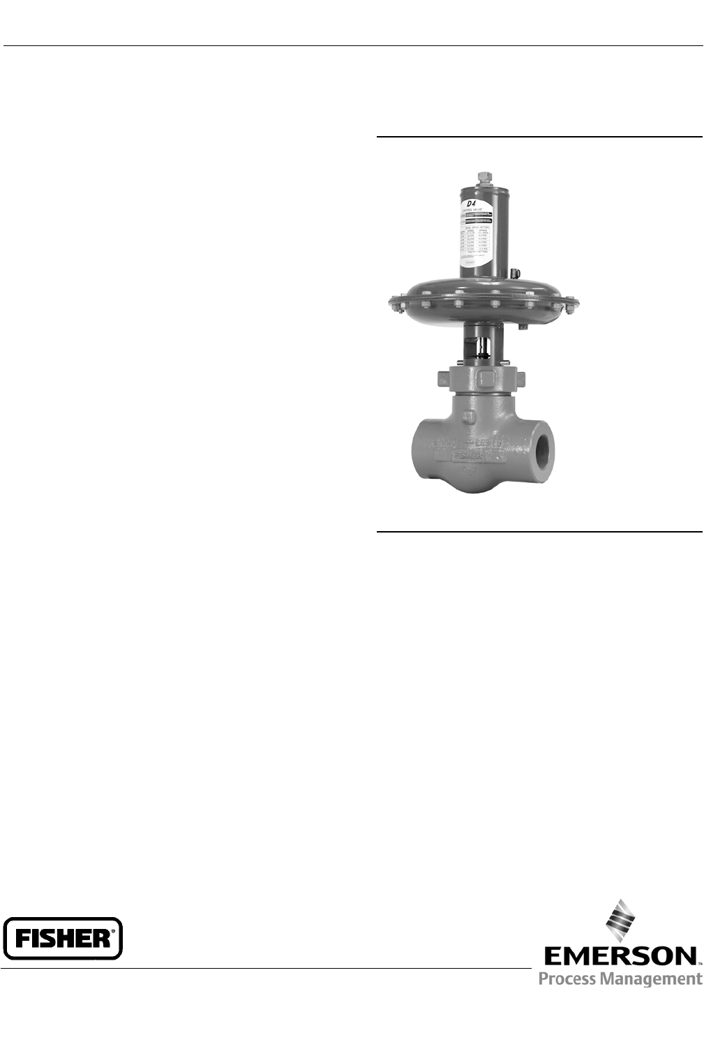
Figure 1. Fisher D4 Control Valve
W8531
Introduction
Scope of Manual
This instruction manual provides installation, maintenance, and parts information for the Fisher D4 control valve.
Do not install, operate, or maintain a D4 control valve without being fully trained and qualified in valve, actuator, and
accessory installation, operation, and maintenance. To avoid personal injury or property damage, it is important to
carefully read, understand, and follow all the contents of this manual, including all safety cautions and warnings. If you
have any questions about these instructions, contact your Emerson Process Management sales office before
proceeding.
Description
The D4 control valve is a compact, rugged valve designed primarily for high-pressure throttling applications. This valve
is ideal for use on pressure and flow control applications within the oil and gas production industry. The D4 valve also
makes an excellent dump valve for high-pressure separators and scrubbers.
The D4 control valve meets the metallurgical requirements of NACE MR0175/ISO 15156 without environmental limits
for temperatures below 135_C(275_F). If the temperature is above 135_C (275_F), the N07718 Belleville washers will
impose some limits, as shown in table 3.
Instruction Manual
D103042X012
D4 Valve
November 2013

Instruction Manual
D103042X012
D4 Valve
November 2013
2
Table 1. Specifications
Available Configurations
Spring-to-Close
Spring-to-Open
Valve Body Sizes and End Connection Styles(1)
See table 2
Maximum Inlet Pressures and Temperatures(1)
If the valve nameplate shows an ASME
pressure-temperature class, maximum inlet pressure
and temperature is consistent with the applicable
class per ASME B16.34. If the nameplate does not
show an ASME class, it will show a maximum cold
working pressure at 38_C(100_F) (for example, 293
bar [4250 psi])
Maximum Pressure Drops(1)
Seetables4,5,6,and7
Input Signal to Actuator
Seetables4,5,6,and7
Actuator Maximum Casing Pressure(1)
3.4bar(50psig)
Shutoff Classification per ANSI/FCI 70-2
and IEC 60534-4
Class IV
Material Temperature Capabilities(1)
Actuator Assembly: -40 to 93C(-40to200F)
Valve Body Assembly:
Standard Bonnet O-Ring: -40 to 135C(-40to275F)
Optional Fluorocarbon Bonnet O-Ring: -23 to 204C
(-10 to 400F)
Flow Characteristic
Equal percentage
Flow Direction
Flow up only
Port Diameters
See table 2
Valve Plug Travel
19 mm (0.75 inch)
Valve Plug Style
Micro-Form valve plug
Actuator Diaphragm Effective Area
452 cm2(69 inches2)
Actuator Pressure Connection Size
1/4 NPT internal
1. The pressure or temperature limits in the referenced tables and any applicable ASME code limitations should not be exceeded.
Specifications
Table 1 lists specifications for the D4 control valve. Some of the specifications for a given control valve as it originally
comes from the factory are stamped on a nameplate located on the actuator spring barrel.
Educational Services
For information on available courses for Fisher D4 valves, as well as a variety of other products, contact:
Emerson Process Management
Educational Services, Registration
P.O. Box 190; 301 S. 1st Ave.
Marshalltown, IA 50158-2823
Phone: 800-338-8158 or
Phone: 641-754-3771
FAX: 641-754-3431
e-mail: education@emerson.com

Instruction Manual
D103042X012
D4 Valve
November 2013
3
Table 2. Valve Sizes and Connection Styles
VALVE
SIZE,
NPS
PORT
DIAMETER,
(INCHES)
SCREWED RAISED FACE (RF) FLANGED RING TYPE JOINT
(RTJ) FLANGED
4250 psi CL150 CL300 CL600 CL900 and
CL1500 CL600 CL900 and
CL1500
10.25, 0.375,
0.5, 0.75 XXXXXXX
20.25, 0.375, 0.5
0.75, 1, 1.25 XXXXXXX
X = Available construction.
Table 3. D4 Environmental Limits for NACE MR0175/ISO 15156 with Sour Trim
MAXIMUM TEMPERATURE MAXIMUM H2S PARTIAL PRESSURE COMPATIBLE WITH
ELEMENTAL SULFUR?
_C_FMPa psia
232 450 0.2 30 No
204 400 1.4 200 No
199 390 2.3 330 No
191 375 2.5 360 No
149 300 2.8 400 No
135 275 No Limit Yes
Table 4. Maximum Shutoff Pressure Drops(1) for Fisher D4 Control Valves (Spring-to-Close)
When Used with Typical Control Instrumentation(2)
INPUT SIGNAL TO
ACTUATOR
0to1.2Bar
(0 to 18 Psig)
0to1.4Bar
(0 to 20 Psig)
0to2.0Bar
(0 to 30 Psig)
0to2.3Bar
(0 to 33 Psig)
0to2.4Bar
(0 to 35 Psig)
0to3.4Bar
(0 to 50 Psig)
SPRING Light Rate Heavy Rate
INITIAL SPRING
SETTING
0.77 Bar
(11.2 Psig)
0.77 Bar
(11.2 Psig)
0.85 Bar
(12.4 Psig)
1.05 Bar
(15.3 Psig)
1.18 Bar
(17.1 Psig)
1.18 Bar
(17.1 Psig)
PORT DIAMETER Maximum Pressure Drop
mm Inches Bar Psi Bar Psi Bar Psi Bar Psi Bar Psi Bar Psi
6.4
9.5
12.7
19.1
25.4
31.8
0.25
0.375
0.5
0.75
1
1.25
293(3)
293(3)
191
80
42
25
4250(3)
4250(3)
2765
1160
610
365
293(3)
293(3)
191
80
42
25
4250(3)
4250(3)
2765
1160
610
365
293
293
219
92
49
30
4250
4250
3180
1340
715
430
293
293
288
123
67
41
4250
4250
4180
1785
965
590
293
293
293
143
78
48
4250
4250
4250
2080
1130
700
293
293
293
143
78
48
4250
4250
4250
2080
1130
700
1. The pressure or temperature limits in the referenced tables and any applicable ASME code limitations should not be exceeded.
2. For example, use the column marked 0-1.4 bar (0-20 psig) for a 0.21-1.0 bar (3-15 psig) pneumatic controller with 1.4 bar (20 psig) supply pressure.
3. For applications with downstream pressure in excess of 196 bar (2845 psig), use 196 bar (2845 psig) for Maximum Shutoff Pressure.
Table 5. Maximum Shutoff Pressure Drops(1) for Fisher D4 Control Valves (Spring-to-Close)
When Used with Instrumentation with Restricted Output Range(2)
INPUT SIGNAL TO
ACTUATOR
0.4 to 2.0 Bar
(6 to 30 Psig)
0.14 to 2.3 Bar
(2 to 33 Psig)
SPRING Heavy Rate Heavy Rate
INITIAL SPRING
SETTING
0.97 Bar
(14.0 Psig)
1.17 Bar
(17.0 Psig)
PORT DIAMETER Maximum Pressure Drop
mm Inches Bar Psi Bar Psi
6.4
9.5
12.7
19.1
25.4
31.8
0.25
0.375
0.5
0.75
1
1.25
293(3)
210(3)
113
45
23
13
4250(3)
3045(3)
1635
655
330
185
293
293
282
120
65
39
4250
4250
4095
1750
945
580
1. The pressure or temperature limits in the referenced tables and any applicable ASME code limitations should not be exceeded.
2.Forexample,anElectro-PneumaticTransducercalibratedfor0.4-2.0bar(6-30psig)outputpressure.
3. For applications with downstream pressure in excess of 118 bar (1715 psig), use 118 bar (1715 psig) for Maximum Shutoff Pressure.

Instruction Manual
D103042X012
D4 Valve
November 2013
4
Table 6. Maximum Shutoff Pressure Drops(1) for Fisher D4 Control Valves (Spring-to-Open)
When Used with Typical Control Instrumentation(2)
INPUT SIGNAL TO
ACTUATOR
0to1.2Bar
(0 to 18 Psig)
0to1.4Bar
(0 to 20 Psig)
0to2.0Bar
(0 to 30 Psig)
0to2.3Bar
(0 to 33 Psig)
0to2.4Bar
(0 to 35 Psig)
0to3.4Bar
(0 to 50 Psig)
SPRING Light Rate Heavy Rate
INITIAL SPRING
SETTING
0.23 Bar
(3.4 Psig)
0.23 Bar
(3.4 Psig)
0.28 Bar
(4.0 Psig)
0.28 Bar
(4.0 Psig)
0.28 Bar
(4.0 Psig)
0.28 Bar
(4.0 Psig)
PORT DIAMETER Maximum Pressure Drop
mm Inches Bar Psi Bar Psi Bar Psi Bar Psi Bar Psi Bar Psi
6.4
9.5
12.7
19.1
25.4
31.8
0.25
0.375
0.5
0.75
1
1.25
293(3)
293(3)
187
78
41
24
4250(3)
4250(3)
2715
1135
600
355
293(3)
293(3)
233
99
53
32
4250(3)
4250(3)
3380
1430
765
465
293
293
293
147
80
49
4250
4250
4250
2130
1160
715
293
293
293
178
97
60
4250
4250
4250
2575
1410
875
293
293
293
198
109
68
4250
4250
4250
2875
1575
985
293
293
293
293
195
123
4250
4250
4250
4250
2830
1785
1. The pressure or temperature limits in the referenced tables and any applicable ASME code limitations should not be exceeded.
2. For example, use the column marked 0-1.4 bar (0-20 psig) for a 0.21-1.0 bar (3-15 psig) pneumatic controller with 1.4 bar (20 psig) supply pressure.
3. For applications with downstream pressure in excess of 190 bar (2760 psig), use 190 bar (2760 psig) for Maximum Shutoff Pressure.
Table 7. Maximum Shutoff Pressure Drops(1) for Fisher D4 Control Valves (Spring-to-Open)
When Used with Instrumentation with Restricted Output Range(2)
INPUT SIGNAL TO
ACTUATOR
0.4 to 2.0 Bar
(6 to 30 Psig)
0.14 to 2.3 Bar
(2 to 33 Psig)
SPRING Heavy Rate Heavy Rate
INITIAL SPRING
SETTING
0.69 Bar
(10.0 Psig)
0.42 Bar
(6.1 Psig)
PORT DIAMETER Maximum Pressure Drop
mm Inches Bar Psi Bar Psi
6.4
9.5
12.7
19.1
25.4
31.8
0.25
0.375
0.5
0.75
1
1.25
293(3)
293(3)
196
82
43
26
4250(3)
4250(3)
2845
1195
630
380
293
293
293
156
85
52
4250
4250
4250
2265
1235
765
1. The pressure or temperature limits in the referenced tables and any applicable ASME code limitations should not be exceeded.
2.Forexample,anElectro-PneumaticTransducercalibratedfor0.4-2.0bar(6-30psig)outputpressure.
3. For applications with downstream pressure in excess of 202 bar (2925 psig), use 202 bar (2925 psig) for Maximum Shutoff Pressure.
Installation
WARNING
Always wear protective gloves, clothing, and eyewear when performing any installation operations to avoid personal
injury.
To avoid personal injury or property damage caused by bursting of pressure-retaining parts or by uncontrolled process
fluid, be certain the service conditions do not exceed the limits shown on the valve nameplate and in tables 1, 4, 5, 6, and 7.
Use pressure-relieving devices required by government or accepted industry codes and good engineering practices.
Check with your process or safety engineer for any additional measures that must be taken to protect against process
media.
If installing into an existing application, also refer to the WARNING at the beginning of the Maintenance section in this
instruction manual.

Instruction Manual
D103042X012
D4 Valve
November 2013
5
WARNING
When ordered, the valve configuration and construction materials were selected to meet particular pressure, temperature,
pressure drop, and controlled fluid conditions. Responsibility for the safety of process media and compatibility of valve
materials with process media rests solely with the purchaser and end-user. Since some body/trim material combinations
are limited in their pressure drop and temperature ranges, do not apply any other conditions to the valve without first
contacting your Emerson Process Management sales office.
WARNING
Avoid personal injury or property damage caused by possible actuator failure. The use of a rigidly-mounted support on the
actuator casing may cause additional stress on the actuator leading to premature wear and/or failure of the actuator
components.
CAUTION
To avoid product damage, inspect the valve before installation for any damage or any foreign material that may have
collected in the valve body. Also remove any pipe scale, welding slag, or other foreign material from the pipeline.
1. Before installing the control valve assembly, inspect it for any damage and for any foreign material that may have
collected in the valve body.
2. Remove any pipe scale, welding slag, and other foreign material from the pipeline.
3. The control valve can be installed in any position, but normally the actuator is vertical above the valve. Install the
valve so the flow direction arrow on the side of the valve indicates the direction of the process flow.
4. Install the valve following local and national piping codes when they apply to the application. For screwed
connections, treat the external pipe threads with a good grade pipe compound. For flanged valves, use suitable
gaskets between valve and pipeline flanges.
5. If continuous operation is required during maintenance and inspection, install a conventional three-valve bypass
around the valve.
6. Connect loading pressure for the Spring-to-Open configuration to the 1/4-18 NPT connection in the upper casing
assembly (key 23) as shown in figure 5. The Spring-to-Close configuration loading pressure connection is in the
lower casing assembly (key 39) as shown in figure 4.
Spring Adjustment
The spring has a fixed pressure span over which loading pressure will stroke the valve. Adjustment of the spring
compression shifts the span so that more or less loading pressure is required to start travel. Since the span does not
change, there will be a corresponding increase or decrease inthepressurerequirementsattheendofthevalvestroke.
In order to maximize shutoff pressure drop values, the actuator spring must be accurately adjusted for each Input
Signal Pressure Range. If the actuator has been disassembled or pressure conditions have changed, the spring may
require adjustment. Refer to tables 2 and 4 to determine the Initial Spring Set values based on the Input Signal range
that is available to the actuator. These values include packing friction.

Instruction Manual
D103042X012
D4 Valve
November 2013
6
Spring-to-Close
Refer to figure 4.
1. Loosen the adjusting screw nut (key 44).
2. Turn the adjusting screw (key 31) clockwise to compress the spring or counterclockwise to decrease spring
compression.
3. After adjustment, tighten the adjusting screw nut (key 44).
Spring-to-Open
Refer to figure 5.
1. Unscrew the spring case assembly (key 27).
2. Turn the adjusting stem nut (key 44) clockwise to compress the spring or counterclockwise to decrease spring
compression.
3. After adjustment, replace the spring case assembly (key 27).
Maintenance
Refer to figure 4.
Valve parts are subject to normal wear and must be inspected and replaced as necessary. The frequency of inspection
and maintenance depends on the severity of the service conditions.
WARNING
Avoid personal injury from sudden release of process pressure or bursting of parts. Before performing any maintenance
operations:
DDo not remove the actuator from the valve while the valve is still pressurized.
DAlways wear protective gloves, clothing, and eyewear when performing any maintenance operations to avoid personal
injury.
DDisconnect any operating lines providing air pressure, electric power, or a control signal to the actuator. Be sure the
actuator cannot suddenly open or close the valve.
DUse bypass valves or completely shut off the process to isolate the valve from process pressure. Relieve process pressure
on both sides of the valve. Drain the process media from both sides of the valve.
DVent the power actuator loading pressure and relieve any actuator spring precompression.
DUse lock-out procedures to be sure that the above measures stay in effect while you work on the equipment.
DThe valve packing box may contain process fluids that are pressurized, even when the valve has been removed from the
pipeline. Process fluids may spray out under pressure when removing the packing hardware or packing rings.
DCheck with your process or safety engineer for any additional measures that must be taken to protect against process
media.
Valve Plug and Seat Ring
The D4 control valve is designed to allow easy access to the valve plug and seat ring without disturbing the packing.
Refer to other sections of this instruction manual if additional maintenance is required.

Instruction Manual
D103042X012
D4 Valve
November 2013
7
Disassembly
1. Remove the loading pressure tubing and any accessories that may hamper disassembly.
2. Break the hammer nut (key 6) loose with a hammer. Continue turning the hammer nut by using a hammer or a
large adjustable wrench, tightened around one ear of the hammer nut. If the bonnet is stuck on the valve, continue
to unscrew the hammer nut. The hammer nut will contact the spring pins (key 7) and will force the bonnet out of
the valve. Carefully lift the actuator, bonnet, and valve plug assembly from the valve body.
WARNING
The spring pins must always be in place during valve operation. They provide a safeguard against injury when the unit is
being disassembled.
3. Use a socket wrench to loosen the seat ring (key 3).
4. Remove the seat ring (key 3) and seat ring gasket (key 9) from the valve body.
5. Inspect parts for wear or damage that would prevent proper operation of the valve body. Carefully clean the seat
ring gasket surfaces and seat ring threads.
WARNING
Becarefultoavoiddamagingtheseatingsurfaceonthevalveplugorseatringasdamageintheseareaswillallow
excessive leakage at shutoff. Avoid damaging the highly polished valve stem surface. A damaged valve stem could cut the
packing and allow process fluid to leak to the atmosphere.
Table 8. Torque for Seat Ring (Key 3)
VALVE SIZE RECOMMENDED TORQUE
NPS NSmLbfSft
1407 300
2698 515
6. For spring-to-close only: To remove the valve plug (key 2), drive out the groove pin (key 4) and unscrew the valve
plug from the stem (key 47). If the groove pin (key 4) is not exposed, verify that downward movement of the stem is
not restricted by instrument linkages attached to the stem (key 47).
If the valve plug cannot be easily unscrewed from the stem, use a punch to keep the stem from turning as the plug is
removed.
7. For spring-to-open only: Toremovethevalveplug(key2),firstremovethespringcaseassembly(key27).Remove
the adjustment screw nut (key 44), the upper spring seat (key 29), and the spring (key 30). Push the adjustment
stem (key 31) fully downward until the diaphragm plate (key 40) contacts the cap screws (key 38), exposing the
groove pin (key 4) in the plug. If the groove pin (key 4) is not exposed, verify that downward movement of the stem
is not restricted by instrument linkages attached to the stem (key 47). Drive out the groove pin (key 4) and unscrew
the valve plug from the stem (key 47).
If the valve plug cannot be easily unscrewed from the stem, use a punch to keep the stem from turning as the plug is
removed.
Assembly
1. Make sure the bonnet O-ring (key 8) is on the bonnet and lubricated with lithium grease (key 49).

Instruction Manual
D103042X012
D4 Valve
November 2013
8
2. Install the plug (key 2) on the stem (key 47) and insert a new groove pin (key 4).
3. Thoroughly clean the seat ring and bonnet threads in the valve body (key 1). Also clean the valve body seat ring
gasket surfaces.
4. Apply anti-seize lubricant (key 54) to the threads of the seat ring (key 3), and its mating threads in the valve body.
5. Apply anti-seize lubricant (key 54) to the seat ring gasket (key 9) and install into the valve body.
6. Screw the seat ring into the valve body. Use a socket wrench to tighten the seat ring to the torque values shown in
table8.Removeallexcesslubricant after tightening.
7. Lubricate (key 54) the threads on the valve body and hammer nut and the contact surfaces of the bonnet and
hammer nut flange. Install the bonnet and actuator assembly with pinned valve plug onto the valve body. Tighten
the hammer nut using an adjustable wrench until the nut stops turning. A few hammer blows will be required to
ensure that the assembly is tight.
8. See the actuator assembly and spring adjustment sections of this manual.
Valve Packing
Note
These instructions apply to valves manufactured with serial numbers equal to and greater than 18679262. See Appendix A for
information on packing constructions with serial numbers less than 18679262.
If your D4 valve assembly has a packing retainer lock ring (see figure 6), proceed to Appendix A.
WARNING
Observe the warning at the start of the Maintenance section.
The valve stem packing can only be accessed from within the valve body. If packing maintenance is required, first
disassemble per steps 1, 2, and 6 or 7 in the Valve Plug and Seat Ring Disassembly section of this document.
Disassembly
1. Unscrew the packing retainer (key 10) from the bonnet (key 5).
2. Remove the five Belleville springs (key 11), packing spacer (key 14), packing (key 13), and two anti-extrusion rings
(key 12) from the bonnet, using a formed wire hook.
3. Clean and inspect the packing box wall to ensure that thepackingsurfacesarenotdamaged.Ifthesurface
condition is damaged, and cannot be improved by light sanding, replace the bonnet by contacting your Emerson
Process Management sales office.
4. Inspect the valve stem for scratches or wear, and valve plug for wear or damage. Replace if necessary.
Instruction Manual
D103042X012
D4 Valve
November 2013
9
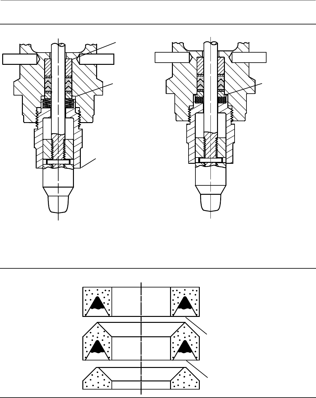
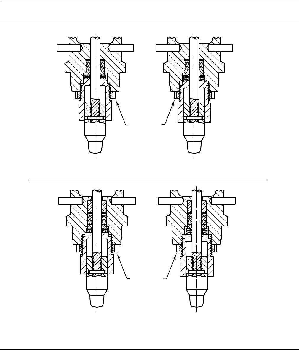
Figure 2. Fisher D4 Packing Installation
VALVE PLUG, BELLEVILLE SPRINGS, AND PACKING RETAINER
CORRECTLY INSTALLED AND TIGHTENED
BELLEVILLE SPRINGS FULLY ENCLOSED BY
THE PACKING RETAINER
PACKING RETAINER
(KEY 8)
UNTIGHTENED,
NOTE THE GAP
FULLY TIGHTENED,
NO GAP
UPPER PACKING
SPACER (KEY 48)
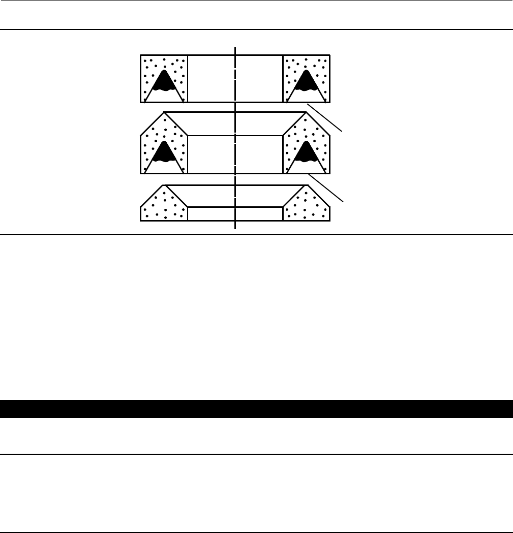
Figure 3. Lubrication Locations on Packing
FEMALE PACKING ADAPTER
MALE PACKING ADAPTER
PACKING RING LUBRICATE WITH 3mm (1/8 INCH
BEAD) OF SUPPLIED HIGH PERFORMANCE
FLUORINATED GREASE
LUBRICATE WITH 3mm (1/8 INCH
BEAD) OF SUPPLIED HIGH PERFORMANCE
FLUORINATED GREASE

Instruction Manual
D103042X012
D4 Valve
November 2013
10
Assembly
Refer to figures 2, 3, 4, and 5.
Note
If your D4 valve assembly has a packing retainer lock ring (see figure 6), proceed to Appendix A.
1. Ensure the upper packing spacer (key 48) is installed, as shown in figure 2.
2. Using a non-marring installation tool, such as a 12-inch length of 1/2 inch PVC pipe, push the first anti-extrusion
washer (key 12) fully into the packing box by hand. Then, use the packing spacer (key 14) to fully seat the
anti-extrusion washer by firmly tapping the packing spacer against the anti-extrusion washer with a hammer and
the PVC pipe.
3. Remove the packing spacer from the packing bore.
CAUTION
All D4 packing kits include a single use packet of high performance fluorinated grease. This is the only acceptable D4
packing lubricant.
Note
In the following procedure, carefully install each packing ring individually over the valve stem and push completely into the
packing box with a non-marring tube. A 12-inch length of 1/2 inch PVC pipe works well for this. It is recommended that the
lubricated packing rings be installed individually rather than pushed in as a set.
4. Apply a 3mm (1/8 inch) bead of the supplied high performance fluorinated grease (key 44) around the groove of
the female packing adaptor as shown in figure 3 and install over the valve stem (key 16).
5. Apply a 3mm (1/8 inch) bead of the supplied high performance fluorinated grease (key 44) around the groove of
the packing ring as shown in figure 3 and install over the valve stem.
6. Install the male packing adaptor, lower anti-extrusion washer (key 10), and lower packing spacer over the valve
stem as shown in figure 2.
7. Firmly press all packing parts into the packing bore with a tube.
8. Install the five Belleville springs (key 11) over the valve stem. The Belleville springs should be single-stacked with the
inside diameter of the inner spring contacting the packing spacer (key 14), and the outside diameter of the outer
spring contacting the packing retainer (key 10).
9. Lubricate the threads of the packing retainer with anti-seize and install into the bonnet using a 1-5/8 inch wrench.
Make sure the Belleville springs are completely enclosed by the packing retainer as shown in figure 2.
10. Torque the packing retainer to 136 NSm(100lbfSft). The packing retainer has been installed correctly when a
metal-to-metal contact has been made between the packing retainer end and the bonnet (key 5). The packing
retainer threads should be completely enclosed by the bonnet.
Actuator (Spring-to-Close)
WARNING
Observe the warning at the start of the Maintenance section.

Instruction Manual
D103042X012
D4 Valve
November 2013
11
Refer to figure 4.
Before disassembling the actuator, disassemble the valve plug, seat ring, and packing according to instructions in this
manual.
Disassembly
1. Loosen the adjusting screw nut (key 44) and turn the adjusting screw (key 31) counterclockwise to remove all
spring compression.
2. Unscrew the casing cap screws and hex nuts (keys 45 and 46), and remove the upper casing assembly (key 23) from
the lower casing (key 39).
3. Remove the spring seat (key 29) and actuator spring (key 30).
4. Lift out the diaphragm, diaphragm plate, and stem assembly. Remove the travel indicator (key 32) when the
bottom of the stem enters the yoke window.
5. To replace the diaphragm (key 15), separate the diaphragm assembly by using a wrench on the hex nuts (key 42) to
unscrew the assembly.
6. Separate the parts--diaphragm washer, actuator O-ring (keys 41 and 25), diaphragm, and diaphragm plate, (keys 15
and 40).
7. Inspect the diaphragm and the actuator O-ring for damage or deterioration, and replace if necessary. If the
diaphragm is replaced, a new O-ring should also be installed.
8. Inspect the stem O-ring (key 19) and bonnet bushing (key 20); replace if necessary. To inspect the casing O-ring
(key 18), remove the cap screws (key 38) and lift off the lower casing (key 39). Replace the O-ring if necessary.
9. Ifthehammernutneedstoberemovedfromthebonnet,thespringpins(key7)canberemovedwithlocking
pliers.
Assembly
1. Before starting assembly, make sure all parts are clean and in good condition. There should be no burrs or sharp
edgesonanythreadsorsurfacesthatmightcutordamage an O-ring, bushing, the packing, or the diaphragm.
When replacing O-rings and bushings, be sure the O-ring or bushing groove is clean and undamaged. Using a
general purpose lubricant (key 49), lubricate all bushings and O-rings and the threads of parts that have to pass
through the bushings and O-rings.
CAUTION
The threads on factory-produced valve stems have been specially machined to avoid O-ring, bushing, or packing damage
during trim maintenance. Use of other than a factory-produced valve stem may result in early stem O-ring, bushing, and
packing failure.
Note
Do not lubricate cap screws (key 38) before inserting them in the following procedure.
2. Place the hammer nut and spring pins on the bonnet, if removed. Install the casing O-ring (key 18), the stem O-ring
(key 19), and the bonnet bushing (key 20). Position the lower casing (key 39) on the bonnet. Insert the
nonlubricated cap screws (key 38), and torque to 49 NSm(36lbfSft).
WARNING
The spring pins must always be in place during valve operation. They provide a safeguard against injury when the unit is
being disassembled.

Instruction Manual
D103042X012
D4 Valve
November 2013
12
3. Assemble the diaphragm plate assembly. Place the patterned side of the diaphragm (key 15) against the diaphragm
plate(key40).Besuretoturnthediaphragmwasher(key41)sothatthesidethatisbeveledontheinsidediameter
is against the O-ring (key 25). Also, make sure that it is assembled for installation with the diaphragm on the loading
pressure side and the lockwasher (key 43) and lower spring seat (key 28) are on the spring side.
4. Fasten the diaphragm and diaphragm plate assembly on the stem with hex nuts (key 42). Place the diaphragm and
diaphragm plate, and stem assembly into the lower casing and bonnet. Install the travel indicator (key 32) on the
stemasthebottomofthestementerstheyokewindow.
CAUTION
Over-tightening the diaphragm casing cap screws and nuts (keys 45 and 46) can damage the diaphragm. Do not exceed 27
NSm (20 lbfSft) torque.
5. Replace the spring (key 30) on the diaphragm plate (key 40). Replace the upper spring seat (key 29). Position the
upper casing (key 23) on the lower casing (key 39). Insert the cap screws (key 45) and tighten the hex nuts (key 46).
Torque the casing cap screws evenly to 27 NSm(20lbfSft) using a crisscross pattern.
6. Adjust the initial spring set per the Spring Adjustment section in this manual.
Actuator (Spring-to-Open)
WARNING
Observe the warning at the start of the Maintenance section.
Refer to figure 5.
Before disassembling the actuator, disassemble the valve plug, seat ring, and packing according to instructions in this
manual.
Disassembly
1. Unscrew the spring case assembly (key 27). Turn the adjusting screw nut (key 44) counterclockwise to remove all
spring compression. Remove the adjusting screw nut, upper spring seat, and spring (keys 44, 29, and 30)
2. Unscrew the casing cap screws and hex nuts (keys 45 and 46), and remove the upper casing assembly (key 23) from
the lower casing (key 39). Remove the cotter pin (key 36) and unscrew the adjusting stem (key 31).
3. Lift out the diaphragm (key 15), diaphragm plate (key 40), and stem assembly. Remove the travel indicator (key 32)
whenthebottomofthestementerstheyokewindow.
4. To replace the diaphragm (key 15), separate the diaphragm assembly by using a wrench on the hex nuts (key 42) to
unscrew the assembly.
5. Separate the parts--diaphragm washer, actuator O-ring (keys 41 and 25), diaphragm, and diaphragm plate, (keys 15
and 40).
6. Inspect the diaphragm and the actuator O-ring for damage or deterioration, and replace if necessary. If the
diaphragm is replaced, a new O-ring should also be installed.
7. Inspect the stem O-ring (key 19) and bonnet bushing (key 20); replace if necessary. To inspect the casing O-ring
(key 18), remove the cap screws (key 38) and lift off the lower casing (key 39). Replace the O-ring if necessary.
Inspect the adjusting stem bushing (key 26) and actuator stem O-ring (key 53). Replace if necessary.

Instruction Manual
D103042X012
D4 Valve
November 2013
13
8. Ifthehammernutneedstoberemovedfromthebonnet,thespringpins(key7)canberemovedwithlocking
pliers.
Assembly
1. Before starting assembly, make sure all parts are clean and in good condition. There should be no burrs or sharp
edgesonanythreadsorsurfacesthatmightcutordamage an O-ring, bushing, the packing, or the diaphragm.
When replacing O-rings and bushings, be sure the O-ring or bushing groove is clean and undamaged. Using a
general purpose lubricant (key 49), lubricate all bushings and O-rings and the threads of parts that have to pass
through the bushings and O-rings.
CAUTION
The threads on factory-produced valve stems have been specially machined to avoid O-ring, bushing, or packing damage
during trim maintenance. Use of other than a factory-produced valve stem may result in early stem O-ring, bushing, and
packing failure.
Note
Do not lubricate cap screws (key 38) before inserting them in the following procedure.
2. Place the hammer nut and spring pins on the bonnet, if removed. Install the casing O-ring (key 18), the stem O-ring
(key 19), and the bonnet bushing (key 20). Position the lower casing (key 39) on the bonnet. Insert the
nonlubricated cap screws (key 38), and torque to 49 NSm(36lbfSft).
3. Assemble the diaphragm plate assembly. Place the patterned side of the diaphragm (key 15) against the diaphragm
plate(key40).Besuretoturnthediaphragmwasher(key41)sothatthesidethatisbeveledontheinsidediameter
is against the O-ring (key 25). Also, make sure that it is assembled for installation with the diaphragm on the loading
pressure side and the lockwasher (key 43) and diaphragm washer (key 41) are on the upper side.
WARNING
The spring pins must always be in place during valve operation. They provide a safeguard against injury when the unit is
being disassembled.
4. Fasten the diaphragm and diaphragm plate assembly on the stem with hex nuts (key 42). Place the diaphragm and
diaphragm plate, and stem assembly into the lower casing and bonnet. Install the travel indicator (key 32) on the
stemasthebottomofthestementerstheyokewindow.
5. Screw the adjusting stem (key 31) onto the stem (key 47) and secure the cotter pin (key 36). Make sure the bushing
and O-ring are in place in the upper casing.
CAUTION
Over-tightening the diaphragm casing cap screws and nuts (keys 45 and 46) can damage the diaphragm. Do not exceed 27
NSm (20 lbfSft) torque.
6. Position the upper casing (key 23) on the lower casing (key 39). Insert the cap screws (key 45) and tighten the hex
nuts (key 46). Torque the casing cap screws evenly to 27 NSm(20lbfSft) using a crisscross pattern.

Instruction Manual
D103042X012
D4 Valve
November 2013
14
7. Replace the spring (key 30), spring seat (key 29), and adjusting stem nut (key 44) over the adjusting stem. Replace
thespringcaseassembly(key27).
8. Adjust the initial spring set per the Spring Adjustment section in this manual.
Parts Ordering
Each D4 control valve is assigned a serial number, which can be found on the nameplate. Refer to the number when
contacting your Emerson Process Management sales office for assistance or when ordering replacement parts.
WARNING
Use only genuine Fisher replacement parts. Components that are not supplied by Emerson Process Management should
not, under any circumstances, be used in any Fisher valve, because they may void your warranty, might adversely affect the
performance of the valve, and could cause personal injury and property damage.
Instruction Manual
D103042X012
D4 Valve
November 2013
15
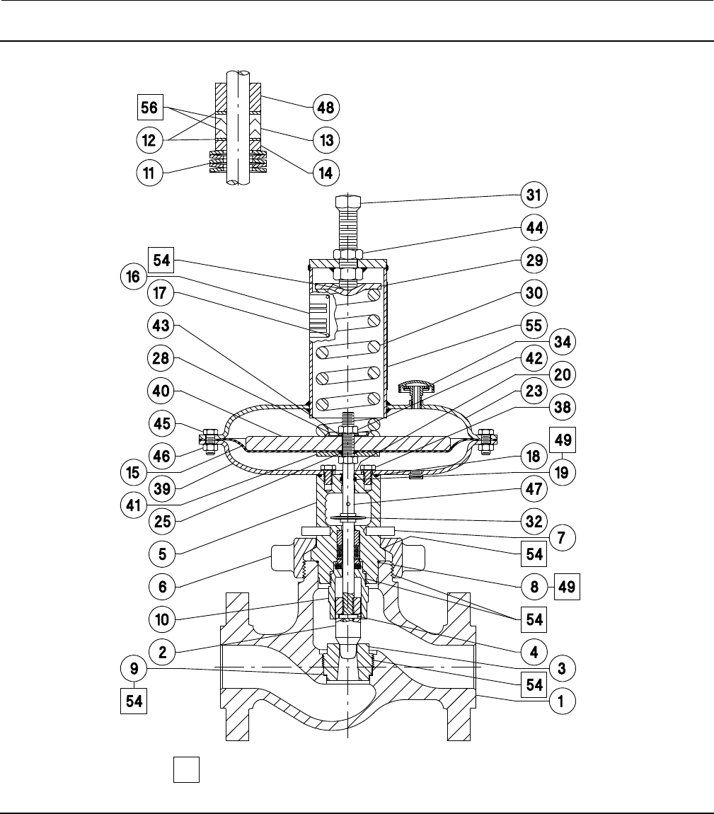
Figure 4. Fisher D4 Valve Assembly (Spring-to-Close)
GE02332-C
BELLEVILLE SPRING
AND PACKING ARRANGEMENT
APPLY LUB
Instruction Manual
D103042X012
D4 Valve
November 2013
16
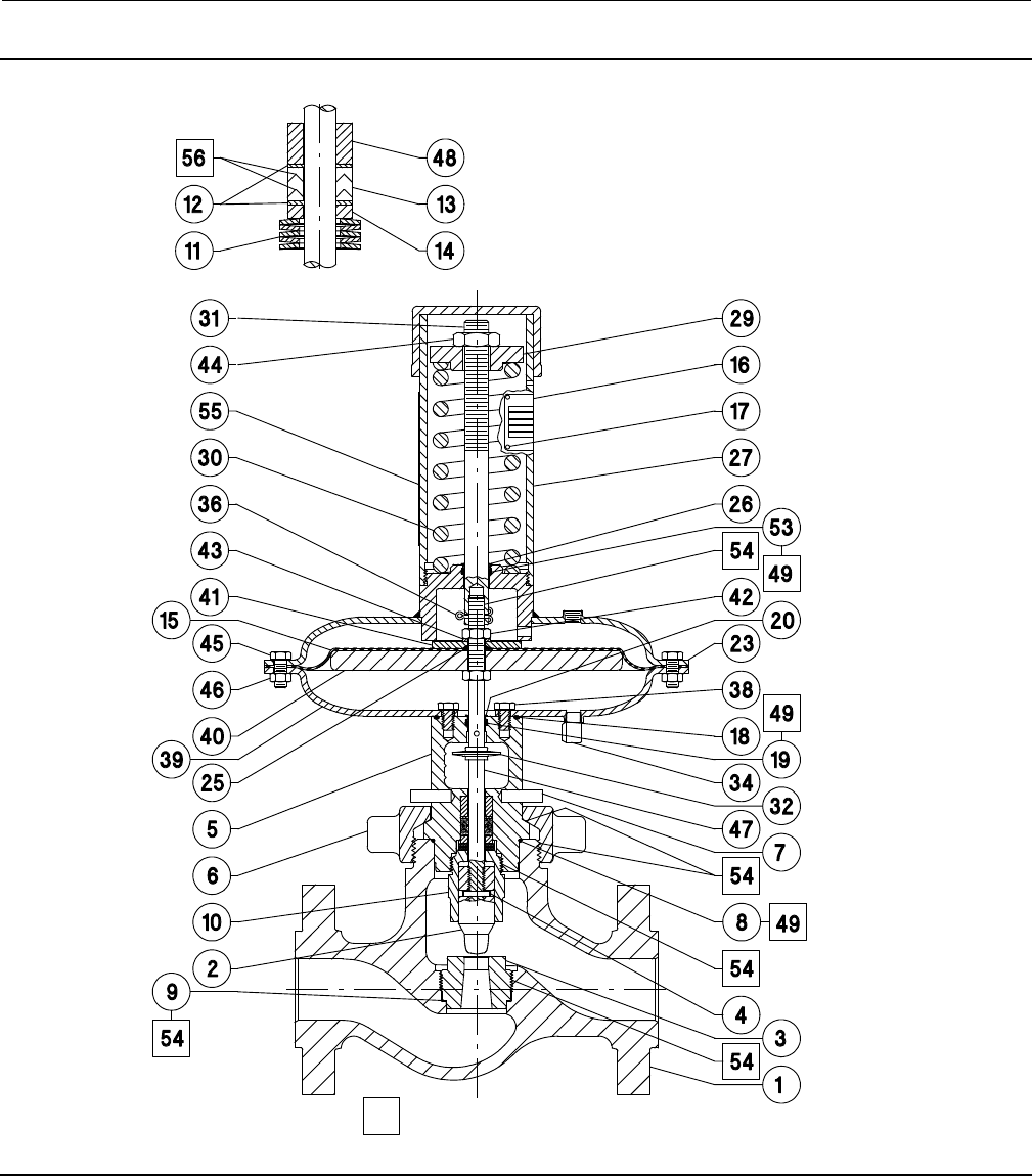
Figure 5. Fisher D4 Valve Assembly (Spring-to-Open)
BELLEVILLE SPRING
AND PACKING ARRANGEMENT
APPLY LUB
GE02334-E

Instruction Manual
D103042X012
D4 Valve
November 2013
17
Repair Kits
Note
All repair kits are supplied with hydrogenated nitrile bonnet O-ring. FKM
(fluorocarbon) bonnet O-ring must be ordered separately when
required.
Description Part Number
* Packing Repair Kit
Includes key numbers 4, 8, 12 (2 req'd),
13, and high performance fluorinated grease RD4X0000012
* ActuatorRepairKit
Includes key numbers 4, 8, 12 (2 req'd), 13,
15, 18, 19, 20, 25, 26, 36, 53, and
high performance fluorinated grease RD4X0000022
Parts List
Note
For part numbers not shown, contact your Emerson Process
Management sales office.
Key Description Part Number
1ValveBody
2* Valve Plug
S41000 / S41600 HT
NPS 1 valve
0.25 inch port diameter 20C3692X012
0.375 inch port diameter 20C3693X012
0.5 inch port diameter 20C3694X012
0.75 inch port diameter GE01557X012
NPS 2 valve
0.25 inch port diameter GE00992X012
0.375 inch port diameter GE00993X012
0.5 inch port diameter GE00994X012
0.75 inch port diameter GE01558X012
1-inch port diameter GE01561X012
1.25 inch port diameter GE01555X012
S17400 H1150 Dbl
NPS 1 valve
0.25 inch port diameter 20C3692X032
0.375 inch port diameter 20C3693X032
0.5 inch port diameter 20C3694X032
0.75 inch port diameter GE01557X032
NPS 2 valve
0.25 inch port diameter GE00992X032
0.375 inch port diameter GE00993X032
0.5 inch port diameter GE00994X032
0.75 inch port diameter GE01558X032
1-inch port diameter GE01561X032
Key Description Part Number
1.25 inch port diameter GE01555X032
Tungsten Carbide
NPS 1 valve
0.25 inch port diameter 20C3696X012
0.375 inch port diameter 20C3697X012
0.5 inch port diameter 20C3698X012
0.75 inch port diameter 20C3699X012
NPS 2 valve
0.25 inch port diameter 20C3682X012
0.375 inch port diameter 20C3683X012
0.5 inch port diameter 20C3685X012
0.75 inch port diameter 20C3686X012
1-inch port diameter 20C3687X012
1.25 inch port diameter 20C3688X012
3* Seat Ring
S17400 H1150 Dbl
NPS 1 valve
0.25 inch port diameter GE00982X032
0.375 inch port diameter GE00983X032
0.5 inch port diameter GE00984X032
0.75 inch port diameter GE00985X032
NPS 2 valve
0.25 inch port diameter GE00986X032
0.375 inch port diameter GE00987X032
0.5 inch port diameter GE00988X032
0.75 inch port diameter GE00989X032
1-inch port diameter GE00990X032
1.25 inch port diameter GE00991X032
Tungsten Carbide
NPS 1 valve
0.25 inch port diameter GE07347X012
0.375 inch port diameter GE07363X012
0.5 inch port diameter GE07364X012
0.75 inch port diameter GE07365X012
NPS 2 valve
0.25 inch port diameter GE07389X012
0.375 inch port diameter GE07394X012
0.5 inch port diameter GE07397X012
0.75 inch port diameter GE07398X012
1-inch port diameter GE07399X012
1.25 inch port diameter GE07406X012
4* Groove Pin GE01163X012
5 Bonnet
6HammerNut
7 Spring Pin
8* Bonnet O-ring
Hydrogenated Nitrile
-46 to 149_C (-50 to 300_F) 10C3680X012
FKM, -23 to 204_C(-10to400_F) 10C3680X022
9* Seat Ring Gasket
For NPS 1 valve 1B198636042
For NPS 2 valve 1B198836042
10 Packing Retainer
11 Belleville Springs, 5 req'd
12* Anti-Extrusion Washer, 2 req'd 12B6335X022
13* Packing Set 12B6667X012
14 Packing Spacer
15* Diaphragm 22B3521X012
16 Nameplate
17 Drive Screw
18* Casing O-ring 1F9141X0142
19* Stem O-ring 1K7561X0072
20* Bonnet Bushing 17A7112X012
23 Upper Casing Assembly
*Recommended spare parts

Instruction Manual
D103042X012
D4 Valve
November 2013
18
Key Description Part Number
25* Actuator O-ring 1K7561X0072
26* Adjusting Stem Bushing (spring-to-open only) 17A4059X012
27 Spring Case Assembly
28 Lower Spring Seat
29 Upper Spring Seat
30 Spring
Spring-to-Close, Light Rate 1F176827092
Spring-to-Close, Heavy Rate 1E792427082
Spring-to-Open, Light Rate 1F176727032
Spring-to-Open, Heavy Rate 1F714327092
31 Adjustment Screw or Stem
32 Travel Indicator
34 Vent Assembly
36* Cotter Pin (spring-to-open only) 1C608035022
37 Pipe Plug
38 Cap Screw
39 Lower Casing
Key Description Part Number
40 Diaphragm Plate
41 Diaphragm Washer
42 Hex Nut
43 Lockwasher
44 Adjustment Screw Nut
45 Cap Screw
46 Hex Nut
47* Valve Stem
S20910, Reverse Acting 20C3681X022
S20910, Direct Acting 20C3716X022
48 Upper packing spacer
49 Lubricant (lithium grease)
51 Drive Screw
53* Actuator Stem O-ring (spring-to-open only) 1C7821X0182
54 Lubricant (anti-seize)
55 Spring Setting Label (not shown)
56 High Performance Fluorinated Grease
Packing Lubricant
*Recommended spare parts

Instruction Manual
D103042X012
D4 Valve
November 2013
19
Appendix A
Note
These instructions apply to valves manufactured with serial numbers less than 18679262.
Valve Packing
WARNING
Observe the warning at the start of the Maintenance section.
The valve stem packing can only be accessed from within the valve body. If packing maintenance is required, first
disassemble per steps 1, 2, and 6 or 7 in the Valve Plug and Seat Ring Disassembly section of this document.
Disassembly
1. Loosen the packing retainer locknut (key 22) with a spanner wrench or with a punch and hammer.
2. Unscrew the packing retainer (key 10) from the bonnet (key 5).
3. Remove the three Belleville springs (key 11), packing spacer (key 14), packing (key 13), and two anti-extrusion rings
(key 12) from the bonnet, using a formed wire hook.
4. Clean and inspect the packing box wall to ensure that thepackingsurfacesarenotdamaged.Ifthesurface
condition is damaged, and cannot be improved by light sanding, replace the bonnet by contacting your Emerson
Process Management sales office.
5. Inspect the valve stem for scratches or wear, and valve plug for wear or damage. Replace if necessary.
Instruction Manual
D103042X012
D4 Valve
November 2013
20
Figure 6. Fisher D4 Belleville Spring Procedure
BELLEVILLE SPRINGS REASONABLY TIGHT
TO SEAT THE PACKING
BELLEVILLE SPRINGS FINGER TIGHT, THEN TIGHTEN
1/2TURN(3FLATSONTHERETAINER)
BONNET DESIGN FOR VALVES (2006 AND NEWER) WITH SERIAL NUMBERS LESS THAN 18679262
BONNET DESIGN FOR VALVES (BEFORE 2006) WITH SERIAL NUMBERS LESS THAN 18679262
BELLEVILLE SPRINGS REASONABLY TIGHT
TO SEAT THE PACKING BELLEVILLE SPRINGS FINGER TIGHT, THEN TIGHTEN
1/2TURN(3FLATSONTHERETAINER)
NOTE: RECOMMENDED SPARE PARTS, INCLUDING PACKING KITS, ARE THE SAME FOR BOTH BONNET DESIGNS.
NOTE: FOR SERIAL NUMBERS GREATER THAN 18679262, SEE THE STANDARD SECTION OF THIS INSTRUCTION MANUAL.
PACKING RETAINER
LOCK RING
(KEY 22)
PACKING RETAINER
LOCK RING
(KEY 22)
Instruction Manual
D103042X012
D4 Valve
November 2013
21
Figure 7. Lubrication Locations on Packing
FEMALE PACKING ADAPTER
MALE PACKING ADAPTER
PACKING RING LUBRICATE WITH 3mm (1/8 INCH
BEAD) OF SUPPLIED HIGH PERFORMANCE
FLUORINATED GREASE
LUBRICATE WITH 3mm (1/8 INCH
BEAD) OF SUPPLIED HIGH PERFORMANCE
FLUORINATED GREASE
Assembly
Refer to figures 6 and 7.
1. Install new packing and Belleville springs according to the packing arrangement shown in figure 6.
2. Using a non-marring installation tool, such as a 12-inch length of 1/2 inch PVC pipe, push the first anti-extrusion
washer (key 12) fully into the packing box by hand. Then, use the packing spacer (key 14) to fully seat the
anti-extrusion washer by firmly tapping the packing spacer against the anti-extrusion washer with a hammer and
the PVC pipe.
3. Remove the packing spacer from the packing bore.
CAUTION
All D4 packing kits include a single use packet of high performance fluorinated grease. This is the only acceptable D4
packing lubricant.
Note
In the following procedure, carefully install each packing ring individually over the valve stem and push completely into the
packing box with a non-marring tube. A 12-inch length of 1/2 inch PVC pipe works well for this. It is recommended that the
lubricated packing rings be installed individually rather than pushed in as a set.
4. Apply a 3mm (1/8 inch) bead of the supplied high performance fluorinated grease (key 44) around the groove of
the female packing adaptor as shown in figure 7 and install over the valve stem (key 16).
5. Apply a 3mm (1/8 inch) bead of the supplied high performance fluorinated grease (key 44) around the groove of
the packing ring as shown in figure 7 and install over the valve stem.
6. Install the male packing adaptor, lower anti-extrusion washer (key 10), and lower packing spacer over the valve
stem as shown in figure 6.
7. Firmly press all packing parts into the packing bore with a tube.

Instruction Manual
D103042X012
D4 Valve
November 2013
22
8. Install the Belleville springs (key 11). The Belleville springs (key 11) should be single stacked with the I.D. of the
inner spring contacting the packing spacer (key 14) and the O.D. of the outer spring contacting the packing retainer
(key 10). The final Belleville spring should be within the 1.26 inch diameter bore of the bonnet.
9. Adjust the packing retainer by hand until it makes contact with the Belleville springs. Do not tighten by hand, simply
install the packing retainer until it makes contact with the Belleville springs. Tighten the packing retainer clockwise
precisely 1.16 turns (7 flats on the retainer) to seat the packing. This should fully compress the Belleville springs as
detected by an increase in torque between 6 and 7 flats.
10. Loosen the packing retainer completely. Adjust the packing retainer by hand until it makes contact with the
Belleville springs. Do not tighten by hand, simply install the packing retainer until it makes contact with the
Belleville springs. Tighten the packing retainer clockwise precisely 1/2 turn (3 flats on the retainer).
11. Lock the packing retainer (key 10) solidly in place by tightening the packing retainer locknut (key 22) using a
spanner wrench or a hammer and punch or chisel.

Instruction Manual
D103042X012
D4 Valve
November 2013
23

Instruction Manual
D103042X012
D4 Valve
November 2013
24
Emerson Process Management
Marshalltown, Iowa 50158 USA
Sorocaba, 18087 Brazil
Chatham, Kent ME4 4QZ UK
Dubai, United Arab Emirates
Singapore 128461 Singapore
www.Fisher.com
The contents of this publication are presented for informational purposes only, and while every effort has been made to ensure their accuracy, they arenot
to be construed as warranties or guarantees, express or implied, regarding the products or services described herein or their use or applicability. All sales are
governed by our terms and conditions, which are available upon request. We reserve the right to modify or improve the designs or specifications of such
products at any time without notice.
E2002, 2013 Fisher Controls International LLC. All rights reserved.
Fisher is a mark owned by one of the companies in the Emerson Process Management business unit of Emerson Electric Co. Emerson Process Management,
Emerson, and the Emerson logo are trademarks and service marks of Emerson Electric Co. All other marks are the property of their respective owners.
Neither Emerson, Emerson Process Management, nor any of their affiliated entities assumes responsibility for the selection, use or maintenance
of any product. Responsibility for proper selection, use, and maintenance of any product remains solely with the purchaser and end user.
