Emerson Fisher Easy E Ed Brochure
2015-03-30
: Emerson Emerson-Fisher-Easy-E-Ed-Brochure-680721 emerson-fisher-easy-e-ed-brochure-680721 emerson pdf
Open the PDF directly: View PDF ![]() .
.
Page Count: 24
Fisher® LNG Liquefaction Solutions
Proven control valve technology for your LNG facility
2 | Fisher® LNG Liquefaction Solutions
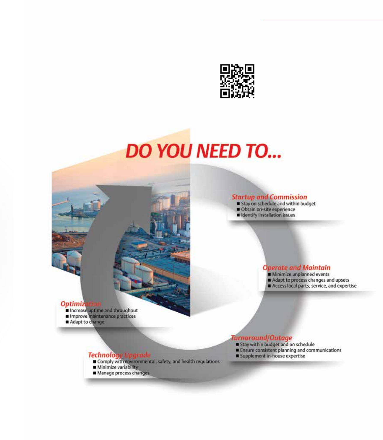
Let Emerson Help Solve Your Toughest Challenge
Your plant must produce LNG at an efficient and constant rate. If you don’t meet your production obligations,
you not only lose revenue, you may be subject to contractual penalties. This means the control valves in
your facility must operate reliably, the way you need them to in your most critical applications 24/7—with no
surprises—to help your facility operate at its nameplate capacity.
Please use this brochure as a guide to discovering the breadth of Fisher® control valve solutions for the most
critical applications in your LNG facility.
1
1
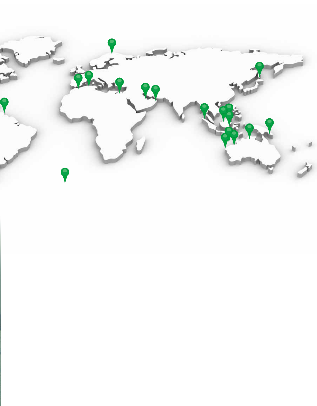
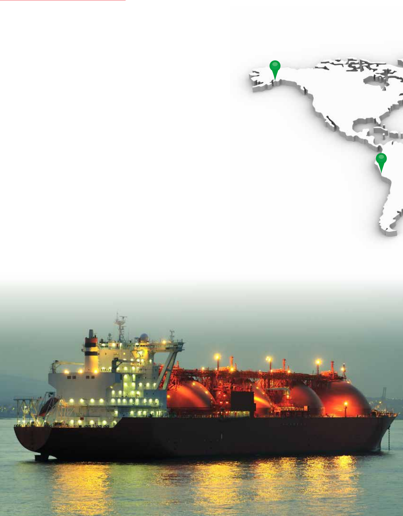
A History of Proven Results
From the first LNG facilities built in Alaska, Brunei, and Algeria in the 1960s and 1970s, to the most
advanced facilities currently under development, Fisher valves can be found in the majority of
liquefaction facilities in the world. In fact, more than 70 percent of existing LNG production flows
through Fisher valves.
More than 40 years of experience in LNG has allowed Emerson to develop reliable, field-proven
Fisher solutions for your most critical applications. By partnering with Emerson, you’ll be able to
leverage our wealth of LNG experience and utilize proven Fisher technologies to help you ensure
the reliability of your plant. From the feed gas pipeline to the export jetty, the Fisher brand is the
name to trust in LNG.
Number of LNG Trains Utilizing Fisher Control Valves
Fisher® LNG Liquefaction Solutions | 3
1
4
4
13 2
2
12
2
2
35
3
2
5
87
2
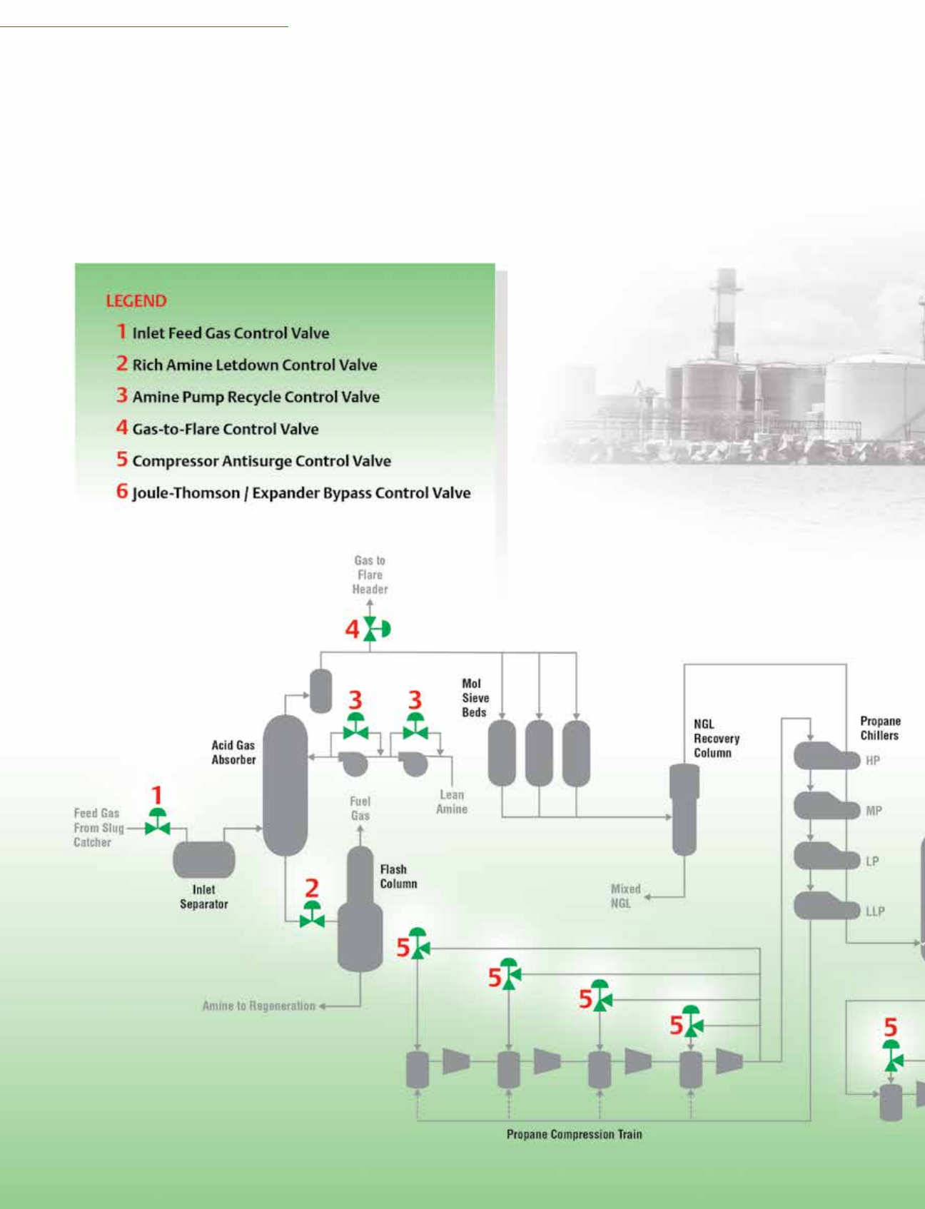
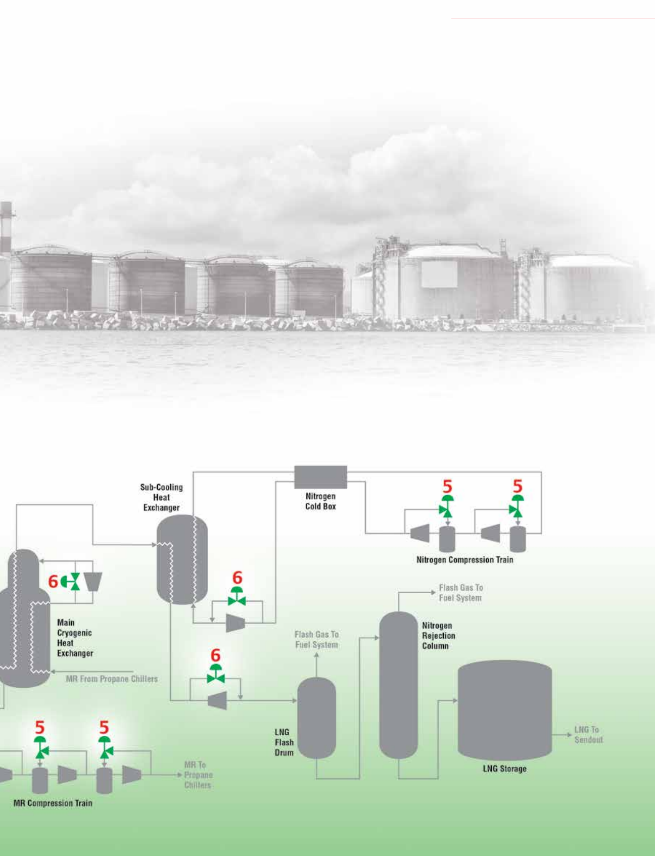
The majority of existing LNG plants utilize a variation of the propane pre-cooled, mixed refrigerant liquefaction process. This process utilizes
propane refrigerant to chill the feed gas and a mixed refrigerant to achieve liquefaction and sub-cooling. Most recent variations of the process
produce 4.0 — 5.0 megatons per annum (mtpa) of output per train. Greeneld plants will commonly consist of one to three trains with room
for additional trains depending on long term feed gas supply. Larger-scale variations of the process utilize a third refrigerant loop of nitrogen
to achieve sub-cooling, and have been used to achieve nearly 8.0 mtpa of output per train. This “mega train” conguration is featured in the
process diagram below.
Typical Mixed Refrigerant Liquefaction Process
4 | Fisher® LNG Liquefaction Solutions
Fisher® LNG Liquefaction Solutions | 5
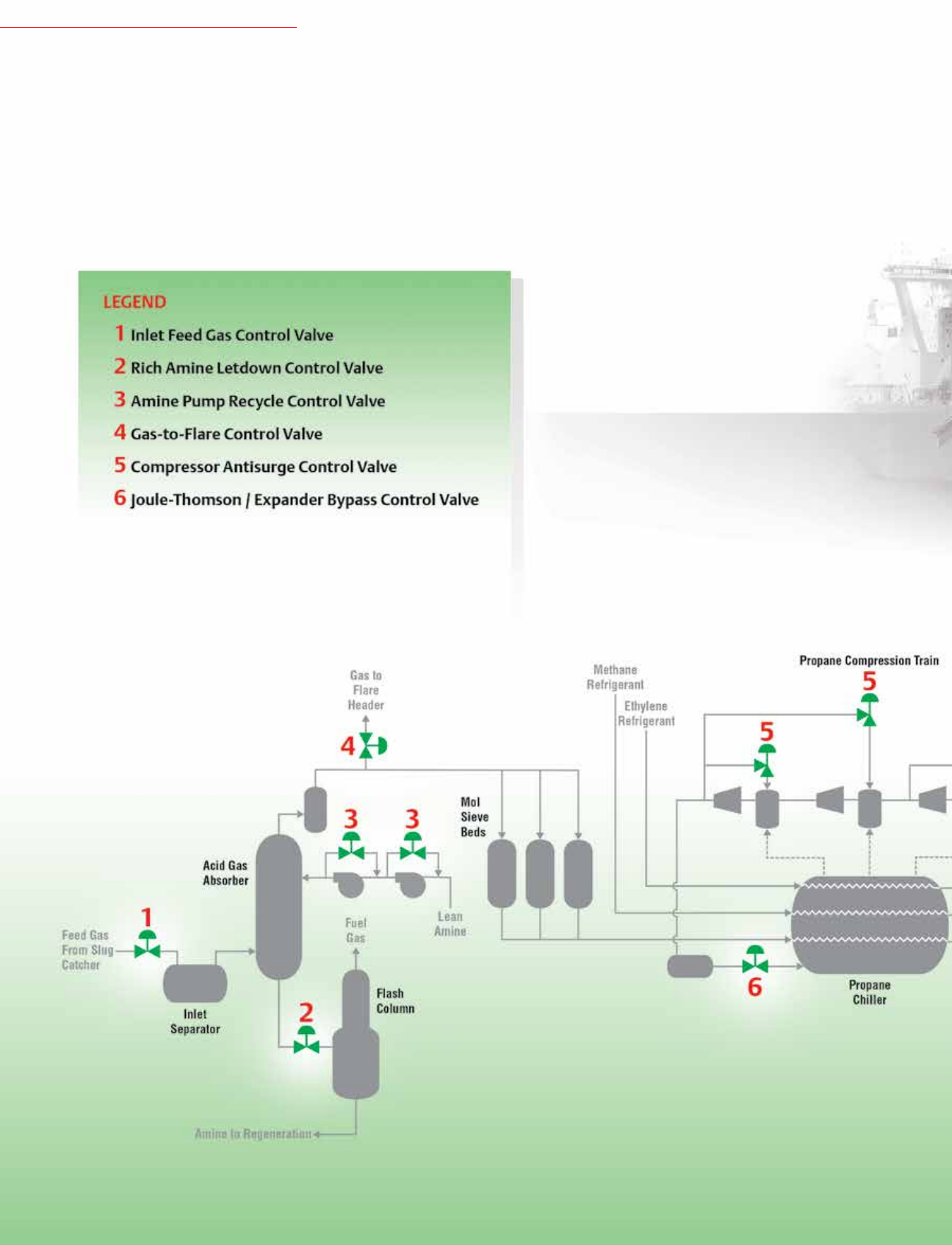
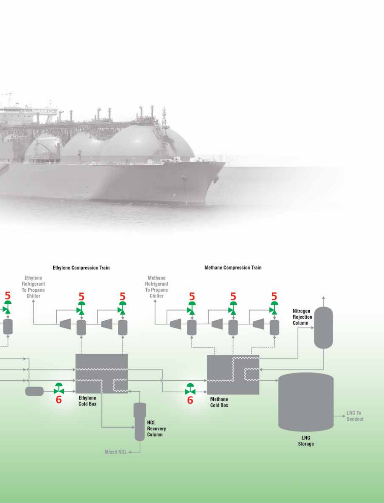
A cascade liquefaction process typically utilizes three pure-component refrigerant loops: propane, ethylene, and methane. Feed gas is
pre-cooled as it passes through the propane chiller before undergoing liquefaction and sub-cooling through ethylene and methane cold
boxes. Most recent variations of the process produce 4.5 — 5.2 mtpa per train. Greeneld plants will commonly consist of one to three trains
with room for additional trains depending on long term feed gas supply.
Typical Cascade Liquefaction Process
6 | Fisher® LNG Liquefaction Solutions
Fisher® LNG Liquefaction Solutions | 7
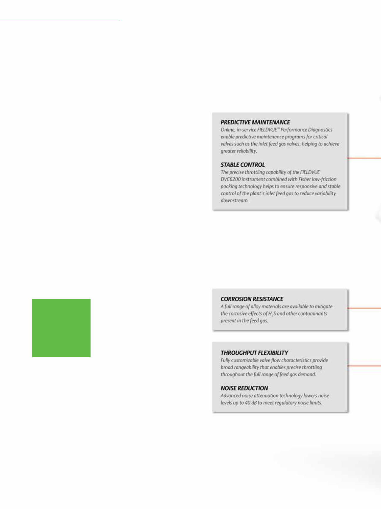
Inlet Feed Gas Control Valve
The inlet receiving facilities serve a number of functions that
are critical to the smooth operation of the entire facility. The
receiving facilities knock out any liquids present in the feed
gas, reduce the pressure from the gas pipeline, and throttle
the ow of gas into the downstream processing units. Stable
and reliable operation of the receiving facilities lays the
foundation for the protable operation of the entire facility.
The location of the inlet feed gas valves will depend on the
extent of gas treatment located onsite. If the facility includes a
gas treatment unit and receives raw feed gas from production,
the inlet valve is located upstream of the acid gas removal
unit. If the liquefaction plant receives sales-quality gas from
the local grid, which requires minimal treatment, the valve will
be located upstream of the liquefaction trains.
At some facilities, a single large valve is used in this
application. At others, a number of smaller valves in parallel
will be used to control the ow of the feed gas. Reliability is the
foremost requirement for the inlet feed valves. Unexpected
maintenance or surprise failures have the potential to bring
down LNG production, which can incur signicant contractual
penalties. In addition, these valves must also be able to
provide precise, stable control through a wide range of gas
ow rates from startup and commissioning through full rated
output of the plant. These valves must operate with minimal
variability to ensure stable and predictable performance of
all process units downstream. Depending on the operating
pressure of the pipeline, these valves can also experience a
signicant pressure drop. This can cause the potential for
damaging noise and vibration if not addressed properly.
The operator of a multi-train
liquefaction facility in Australia
needed absolute assurance that
their critical feed gas inlet valves
would provide the proper rate of
flow into the facility. Too much
flow could overwhelm the plant’s
pressure relief capacity, requiring
expensive modifications. Too little flow could restrict the overall
capacity of the entire multi-billion dollar facility.
Emerson engineers developed custom Fisher Whisper Trim
designs for these NPS 12 ANSI 1500 valves tailored specifically to
the noise and capacity requirements of this critical application.
To provide the ultimate assurance that these custom valves
would meet the exacting application requirements, the
valves were flow tested at the Emerson Innovation Center to
demonstrate the maximum capacity.
Flow testing confirmed the actual capacity of the valves to be
within 3% of the design values, well within the plant operator’s
specification.
A Case-In-Point
8 | Fisher® LNG Liquefaction Solutions
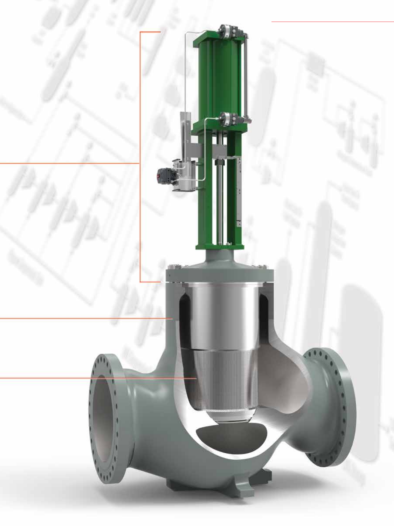
Fisher NPS 30 ET Control Valve with FIELDVUE DVC6200 Digital Valve Controller
Fisher® LNG Liquefaction Solutions | 9
Rich Amine Letdown Control Valve
In facilities that receive raw gas from production, the
acid gas removal unit plays a critical role in the process
by stripping CO2 and/or H2S contaminants from the feed
gas. The presence of these acid gases in excess of specied
limits can cause signicant issues in downstream units. The
presence of H2S can cause serious corrosion issues and CO2
can cause freeze-up in the liquefaction train. As a result,
specications for feed gas are very stringent and typically
require max acid gas content of 50 parts per million (ppm)
CO2 and 2 ppm H2S.
As feed gas enters the contactor at the bottom and ows
upward, lean amine solution owing countercurrent
gradually strips the gas of impurities. The rich amine
letdown valve serves two purposes. First, it regulates the
level of rich amine solution that accumulates in the bottom
of the contactor vessel. Second, it facilitates a pressure
drop into the downstream ash tank, which liberates a
portion of the acid gases entrained in the solution. If not
addressed properly through detailed valve sizing and
selection, this outgassing of the entrained gases can cause
signicant vibration and damage to the valve.
Fisher control valve engineers have decades of experience
with the most severe outgassing applications and have
learned that no two amine letdown applications are
exactly the same. Proprietary outgassing modeling
ensures that the valve type selected is tailored specically
to each application and sized appropriately to mitigate the
gas coming out of the solution.
In some facilities, solids or pipe scale will accumulate in the
bottom of the amine contactor. Emerson offers Fisher dirty
service solutions to prevent plugging while also addressing
the outgassing phenomenon.
10 | Fisher® LNG Liquefaction Solutions
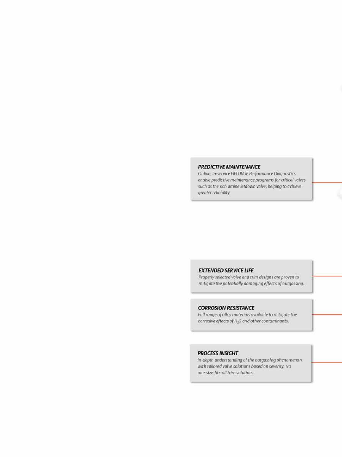
Fisher NPS 16 ET Control Valve with FIELDVUE DVC6200 Digital Valve Controller
Fisher® LNG Liquefaction Solutions | 11
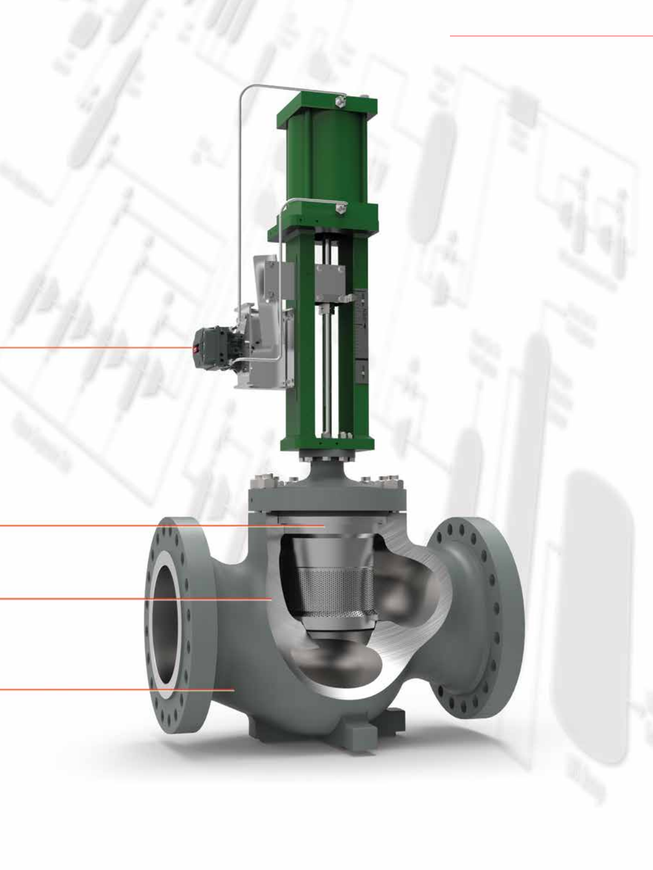
Amine Pump Recycle Control Valve
Maintaining the proper ow of lean amine within the
acid gas removal unit is necessary to ensure sufcient
removal of CO2 and H2S from the feed gas stream. The lean
amine pump ensures the stable ow of lean amine to the
contactor.
The amine pump recycle valve is most commonly used
to facilitate startup and commissioning as the acid gas
removal unit is brought up to capacity. This valve controls
the pump discharge ow that is routed back around to the
suction side of the pump. When needed, the recycle ow
boosts the suction pressure to keep it above the vapor
pressure of the amine. As a result, the amine pump recycle
valve must be very responsive in order to protect the pump
from cavitation damage.
Due to the high pressure differential from discharge back
to suction, the valve trim must be capable of mitigating
the potentially damaging effects of cavitation as it recycles
ow. Any unplanned maintenance on these valves due to
cavitation damage can bring the amine pumps down and
reduce plant throughput.
To learn more about how Fisher anti-
cavitation technologies can help prevent
damage to your valves, view an animation
video at www.FisherSevereService.com
Scan this code to discover the broad
range of Fisher anti-cavitation technology
solutions for both clean and dirty service
applications.
12 | Fisher® LNG Liquefaction Solutions
Fisher NPS 8 ET Control Valve with FIELDVUE DVC6200 Digital Valve Controller
Fisher® LNG Liquefaction Solutions | 13
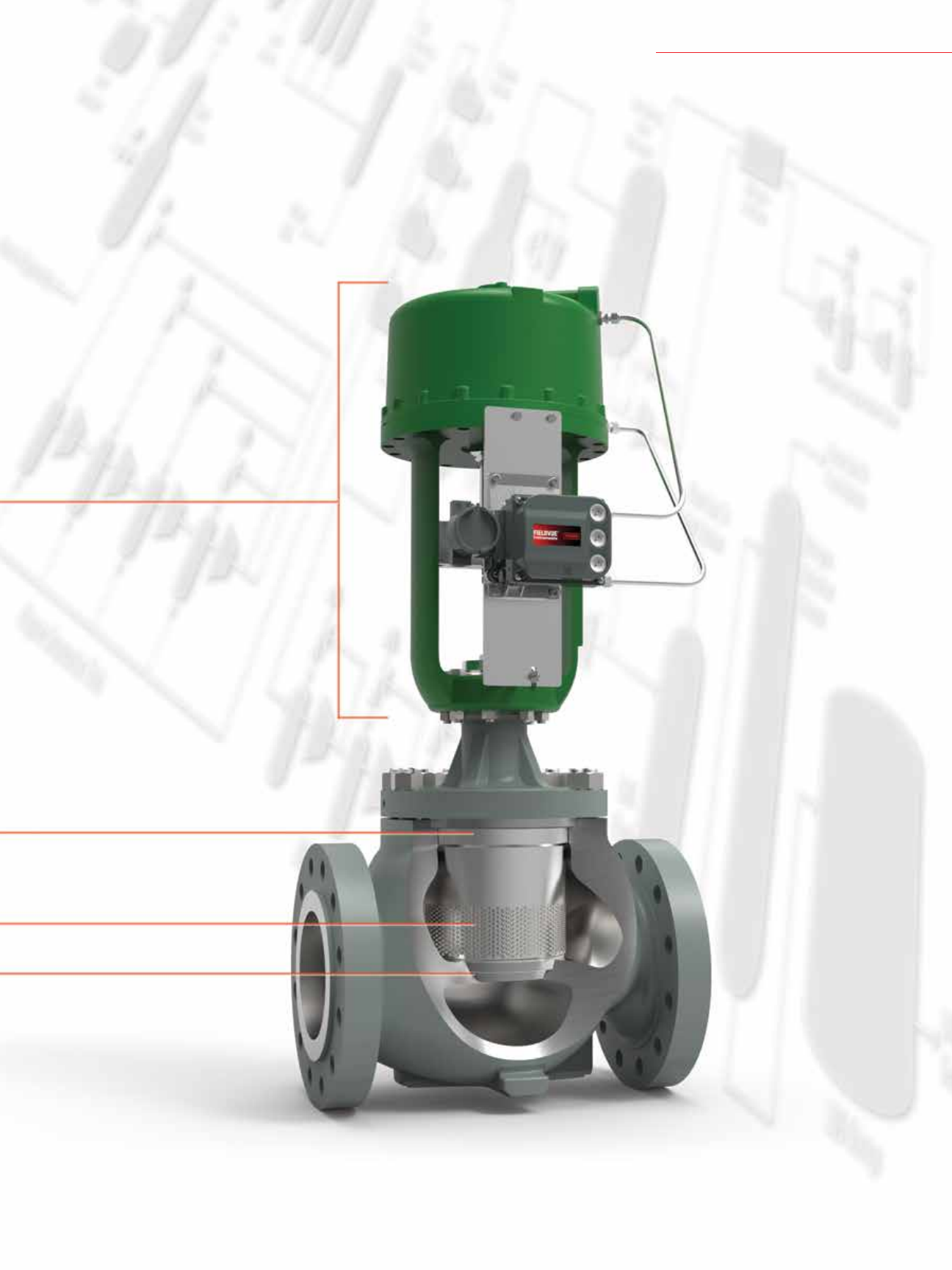
Gas-to-Flare Control Valve
All gas processing facilities have a are system to safeguard against
overpressure of critical assets within the plant and dispose of
any waste gas. Failure of the are system to successfully relieve
pressure from the process can lead to unexpected downtime or
damage to costly pressure-retaining equipment.
Gas-to-are valves are installed at numerous locations throughout
the gas treatment and liquefaction units to control the ow of
feed gas or refrigerant to the are stack for disposal. They are
primarily used during plant startup, shutdown, or short-duration
upset conditions. During these periods, are valves will experience
signicant pressure differentials and high ow rates. If not
addressed properly, these conditions can lead to excessive noise
levels and even damaging vibration.
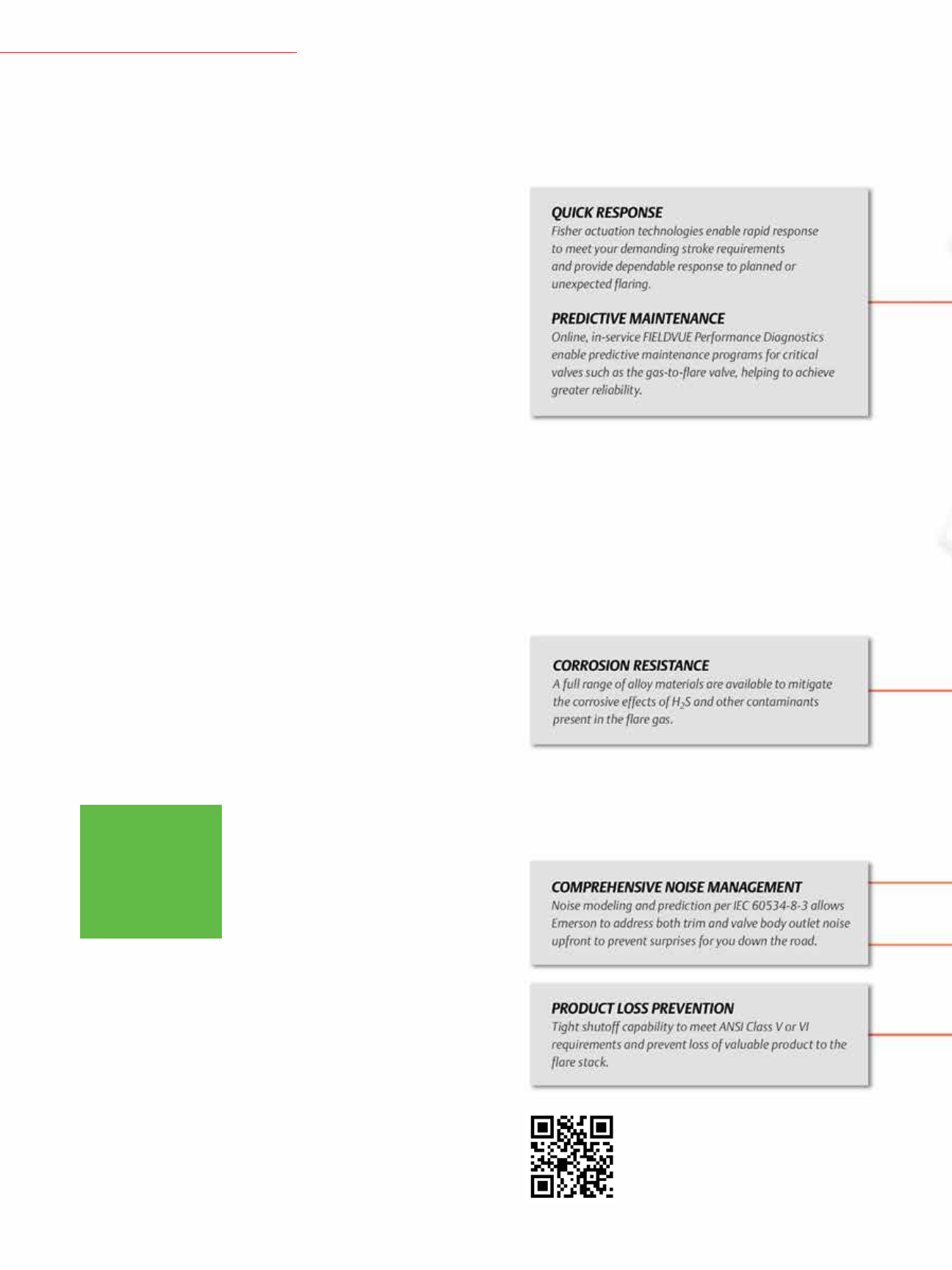
Emerson utilizes the industry standard for aerodynamic noise
modeling and prediction in control valves, IEC 60534-8-3. This
standard models two independent sources of noise -- the valve
trim and the valve body outlet. In applications with moderate
pressure drop, noise attenuating trim is commonly sufcient to
maintain overall noise levels at acceptable levels. However, in
high pressure drop applications such as gas-to-are, the valve
body outlet noise will commonly overcome the trim noise as the
dominant source. To account for this, Emerson’s engineers use the
latest IEC noise prediction model to account for both independent
sources of noise when developing custom valve solutions for your
high pressure drop applications. This comprehensive approach
incorporates noise-attenuating technology to reduce trim noise
and a properly-sized valve body outlet to maintain acceptable
noise levels at the outlet.
During the normal operation of the plant, gas-to-are valves will
remain closed. Because of this, it is important that these valves
maintain tight, long-term shutoff in order to prevent loss of
valuable product to the are stack.
A gas processing plant in Saudi Arabia
experienced cracking of a NPS 54 acid
flare header made of Inconel. Two
Emerson engineers studied the process
conditions and concluded that the
existing valves were contributing to
excessive vibration and noise. Despite the
use of noise-attenuating trim, the valves
had not been properly sized to account for valve body outlet noise,
which resulted in valve outlet velocities close to sonic – 0.7 mach.
After several visits to this remote site, Emerson recommended a larger
replacement valve with Fisher WhisperFlo™ trim that would meet all of
the process conditions.
Existing valves were replaced by two NPS 16 Fisher ET control valves
with WhisperFlo Level Z trim. The valves lowered the velocity of the
outlet to 0.3 mach, which significantly reduced the noise at the valve
and the vibration affecting the downstream piping.
A Case-In-Point
Scan this code or visit
www.FisherSevereService.com
to learn about the science of noise
attenuation in control valves and
our history of solving noise issues in
facilities just like yours.
14 | Fisher® LNG Liquefaction Solutions
Fisher NPS 20 FBT Control Valve with FIELDVUE DVC6200 Digital Valve Controller
Fisher® LNG Liquefaction Solutions | 15
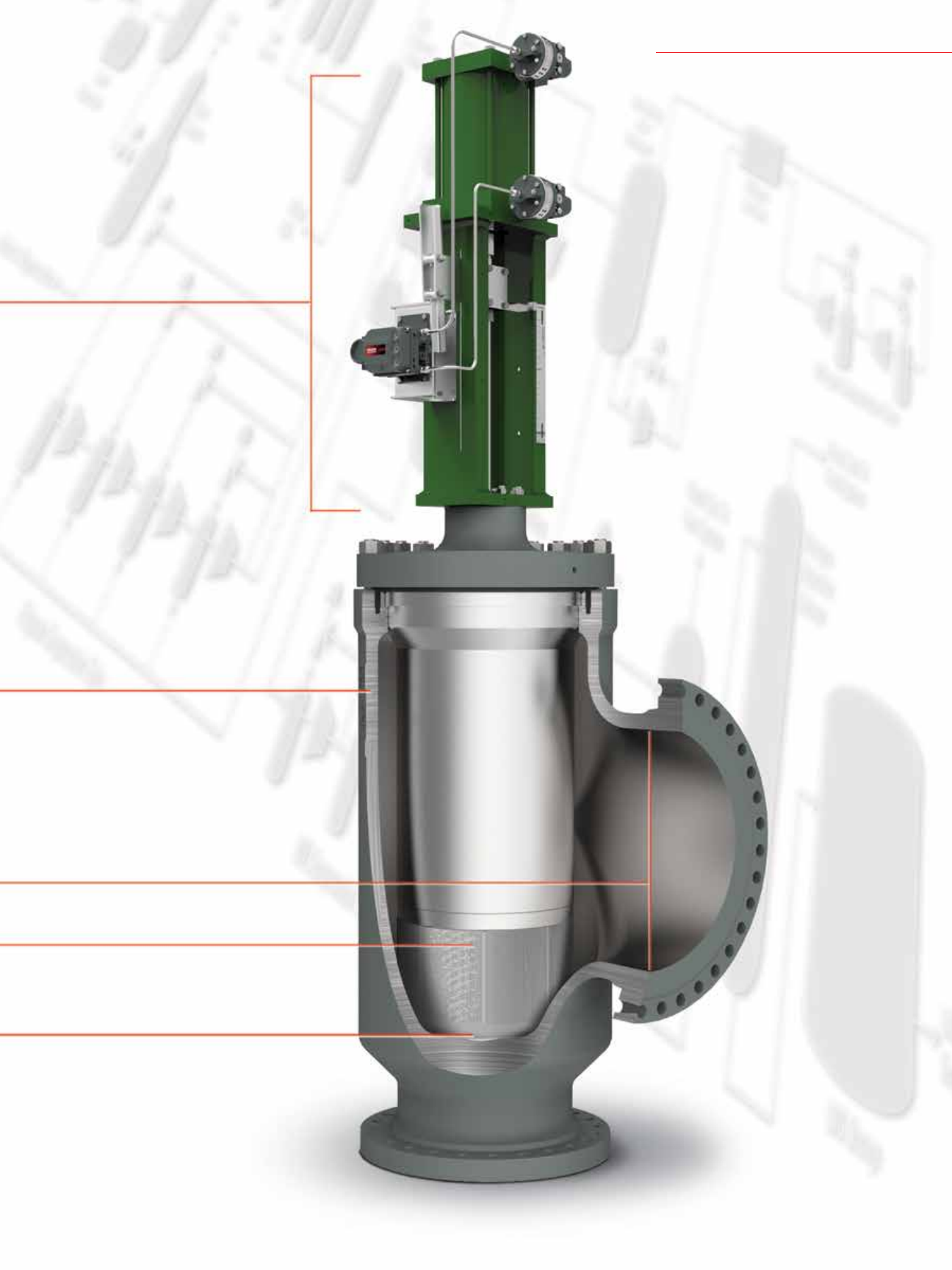
Compressor Antisurge Control Valve
The efciency and availability of a plant’s compressors
both have a direct impact on the protability of the facility.
Unexpected downtime of any of the plant’s refrigerant
loops will lead to reduced LNG production and the
potential for hefty contractual penalties. Compressors also
represent some of the most valuable pieces of equipment
within an LNG facility. Not only will damage to these assets
cause unexpected production downtime, it can also lead
to very costly repairs.
Antisurge valves provide recycle ow to each stage of
the multi-stage compression trains that are common to
liquefaction processes. During startup and commissioning,
the valve provides throttling control to recycle a portion
of the discharge ow as the compressor is brought up to
capacity. During the normal operation of the plant, the
antisurge valve will remain closed or slightly open to allow
for a small portion of the discharge to be recycled. When
closed, it is important that the valve provides tight shutoff
to prevent unwanted recycle ow.
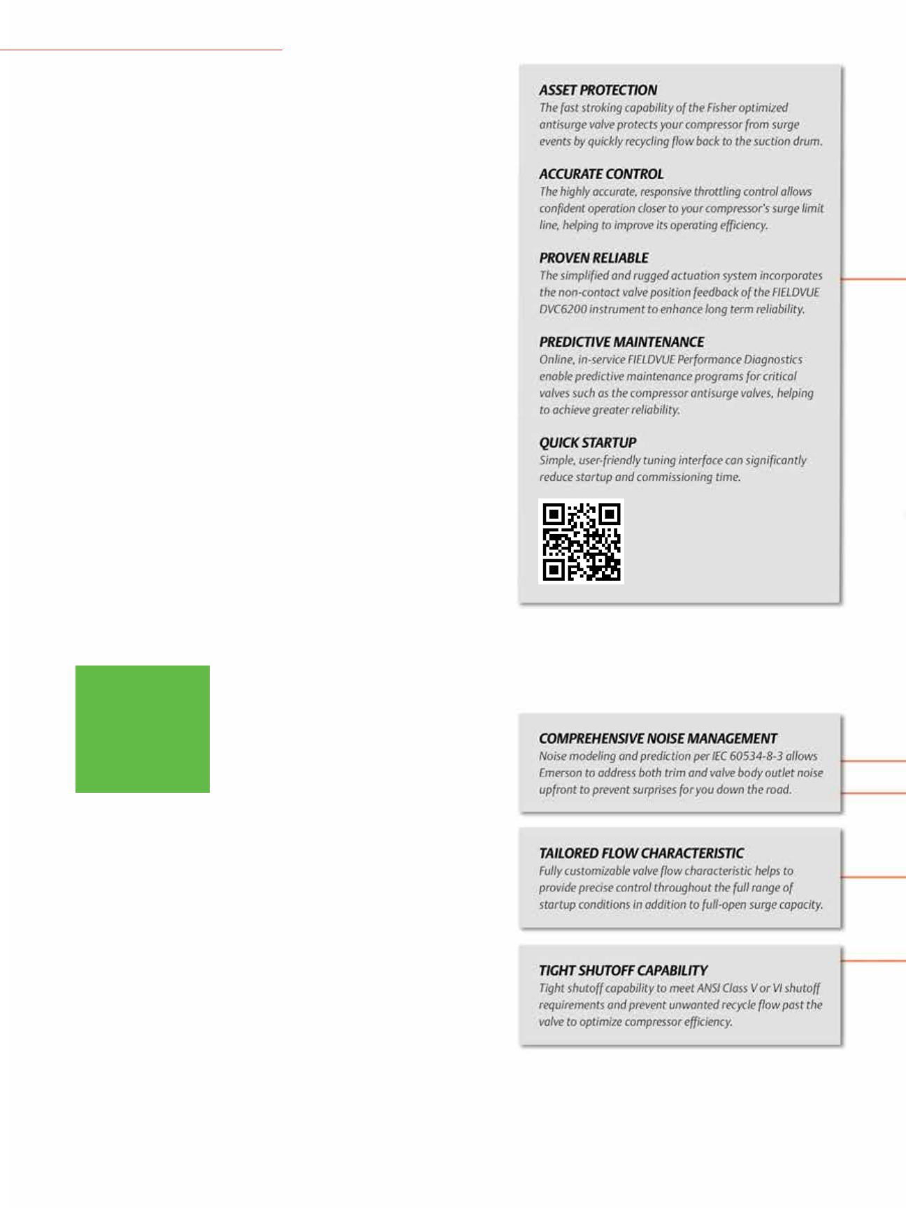
The primary purpose of the antisurge valves is to protect
the most critical and expensive pieces of equipment in the
plant, the compressors. During a surge event, the valve
must open in one to two seconds to recycle the discharge
ow back around to the suction side of the compressor.
Failure of the valve to react quickly to the antisurge
controller can result in severe damage to the impellers of
the compressor from the reversed ow of a surge event.
An LNG facility in Brunei needed
to replace all of its existing
propane and mixed refrigerant
compressor antisurge valves.
After seeing a demonstration of
the Fisher optimized antisurge
valve, the plant turned to
Emerson who has proven its
ability to understand and meet stringent valve performance
criteria.
The 25 existing valves were replaced by NPS 12 through NPS
30 Fisher optimized antisurge valves.
•The valves open in less than two seconds, as well as meet
stringent closed-loop control criteria.
•The measured linearity is less than 0.75%, and the valves
have minimal overshoot in the open and closed directions.
• It often requires about 12 hours to tune a non-Fisher
antisurge valve. With its fewer accessories and diagnostic
capabilities, tuning time for a Fisher optimized antisurge
valve takes only minutes.
All this added up to an antisurge valve solution that helped
to protect compressors and increase process efficiency.
Scan this code to learn more about
the Fisher optimized antisurge
solution designed specifically for
antisurge applications.
A Case-In-Point
16 | Fisher® LNG Liquefaction Solutions
Fisher NPS 42 FBT Control Valve with Optimized Digital Valve Actuation
Fisher® LNG Liquefaction Solutions | 17
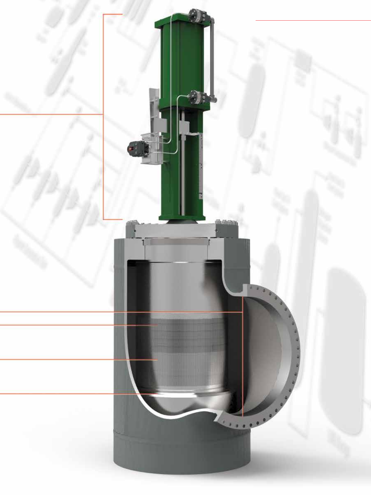
Joule-Thomson/Expander Bypass Control Valve
The Joule-Thomson effect is leveraged throughout all of
the primary liquefaction processes to achieve cooling
of the feed gas or the refrigerant streams. It is used to
achieve cooling of liquids, gases, or multi-phase uids.
Traditionally, this effect has been facilitated by a control
valve that reduces the pressure of the uid signicantly
and induces the desired cooling. Because of the elevated
pressure drop, the valve can experience excessive noise
levels if not addressed properly. It also experiences very
low process temperatures and must be capable of precise
throttling down to full cryogenic temperatures.
In some facilities, expanders are utilized to facilitate
Joule-Thomson cooling while also recovering energy from
the uid to improve overall process efciency. Expanders
are used in both gas and liquid applications (commonly
referred to as hydraulic turbines in liquid applications).
Regardless of the uid, expander bypass valves are
installed in parallel with expanders to ensure process
availability. In instances when the expander is required to
go ofine, the bypass valve is opened to facilitate Joule-
Thomson cooling of the process stream and allow the unit
to continue operating in the absence of the expander. The
bypass valve must be highly responsive and reliable to
ensure process availability. It is also commonly subjected
to a large pressure differential, which creates the potential
for signicant noise levels in gas applications and ashing
in liquid applications.
18 | Fisher® LNG Liquefaction Solutions
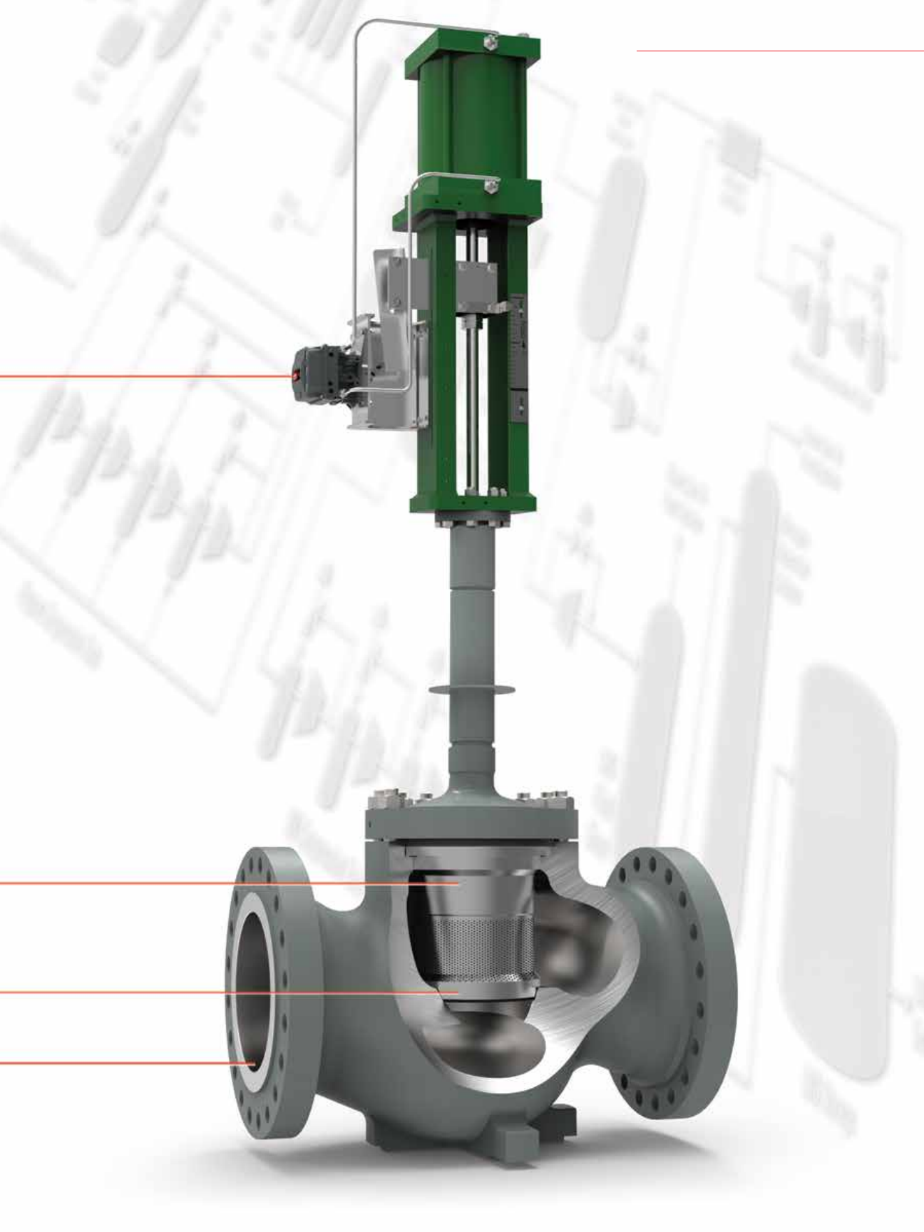
Fisher NPS 16 ET Control Valve with FIELDVUE DVC6200 Digital Valve Controller
Fisher® LNG Liquefaction Solutions | 19
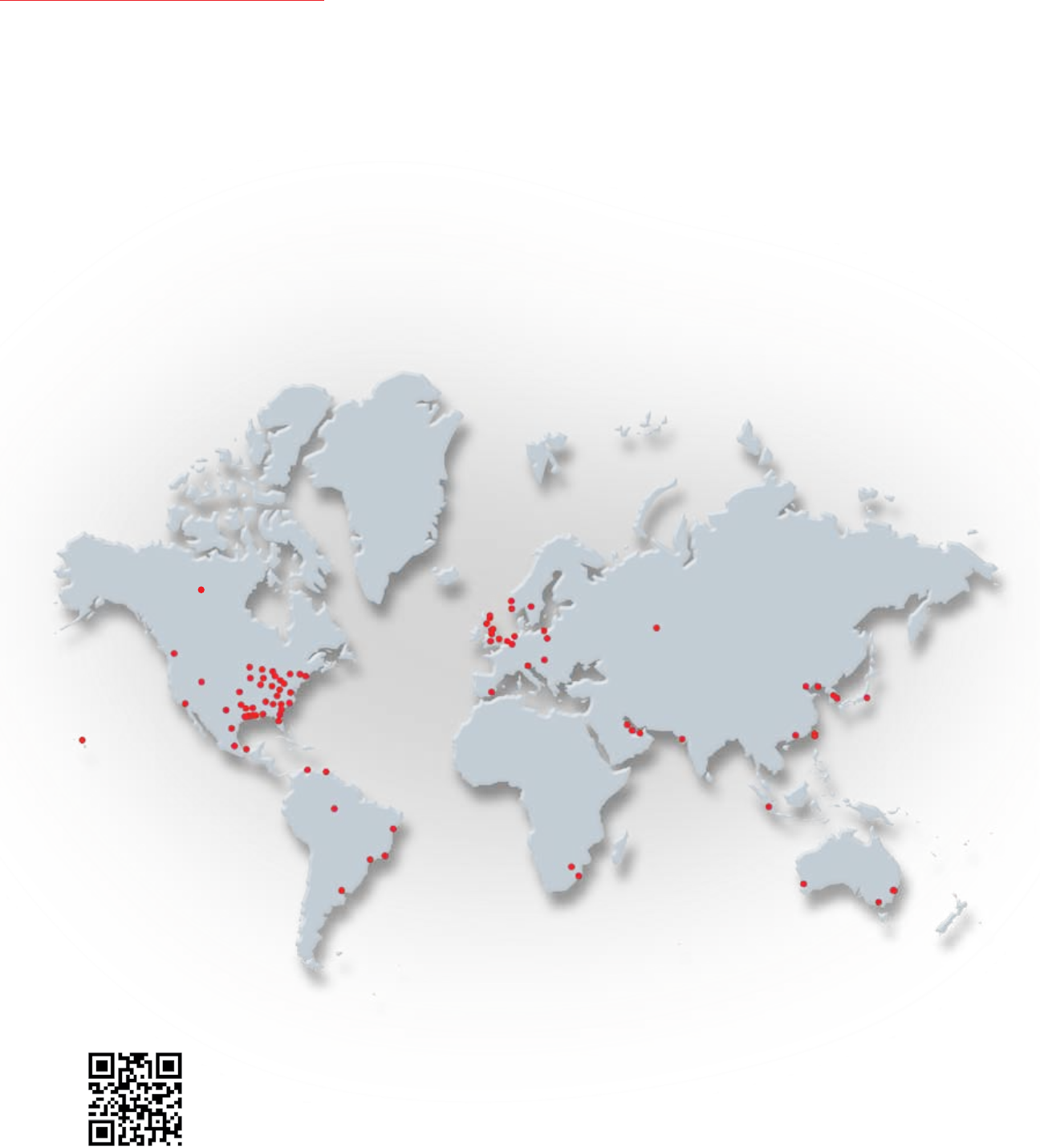
The way you manage key production assets like control valves directly affects your plant’s efficiency, reliability, and profitability. Emerson
Process Management’s Fisher Services provides trusted expertise for control valve maintenance and repair.
Whether you’re starting or commissioning a process, scheduling diagnostics and repair, or planning a turnaround with upgrades to optimize
and extend your plant’s lifecycle, our network of owned and authorized service centers around the world provide effective maintenance
through a network of experienced, highly skilled technicians when and where you need them.
To help you maintain your plant’s efficiency and reliability, Fisher Services uses only certified OEM parts and assemblies sourced through local
inventories, regional parts distribution centers, and Quick Ship facilities to deliver unmatched response to customer needs.
You’re Never Alone
Contact your local sales office to
get in touch with the Service Center
nearest you. To learn more, scan the
QR code or visit www.Fisher.com.
20 | Fisher® LNG Liquefaction Solutions
THE CONTROL VALVE YOU CHOOSE MATTERS
WHEN YOU HAVE TO ACHIEVE EFFICIENT,
PRODUCTIVE, AND RELIABLE PLANT OPERATION.
When you buy Fisher control valves, you get the application expertise that comes from more than forty years of
experience in the LNG industry. Plus you benefit from millions of dollars of research invested in reliability-centric
testing of Fisher control valve technologies.
Fisher product specifications are, in many cases, more stringent than the industry accepted standards set
by regulatory agencies. Our attention to and evaluation of product quality is necessary to bring you Fisher
technologies of the highest reliability and performance.
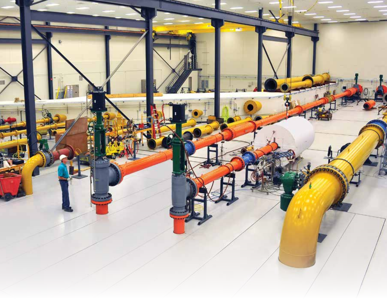
Using Fisher technology can help you achieve efficient, productive, and reliable plant operation. Want to see for
yourself? Visit the Emerson Innovation Center for Fisher Technology in Marshalltown, Iowa, USA. To schedule a
visit, please contact your local Emerson sales office.
Fisher technology development capabilities extend worldwide with engineers and labs in North America, Europe,
and Asia.
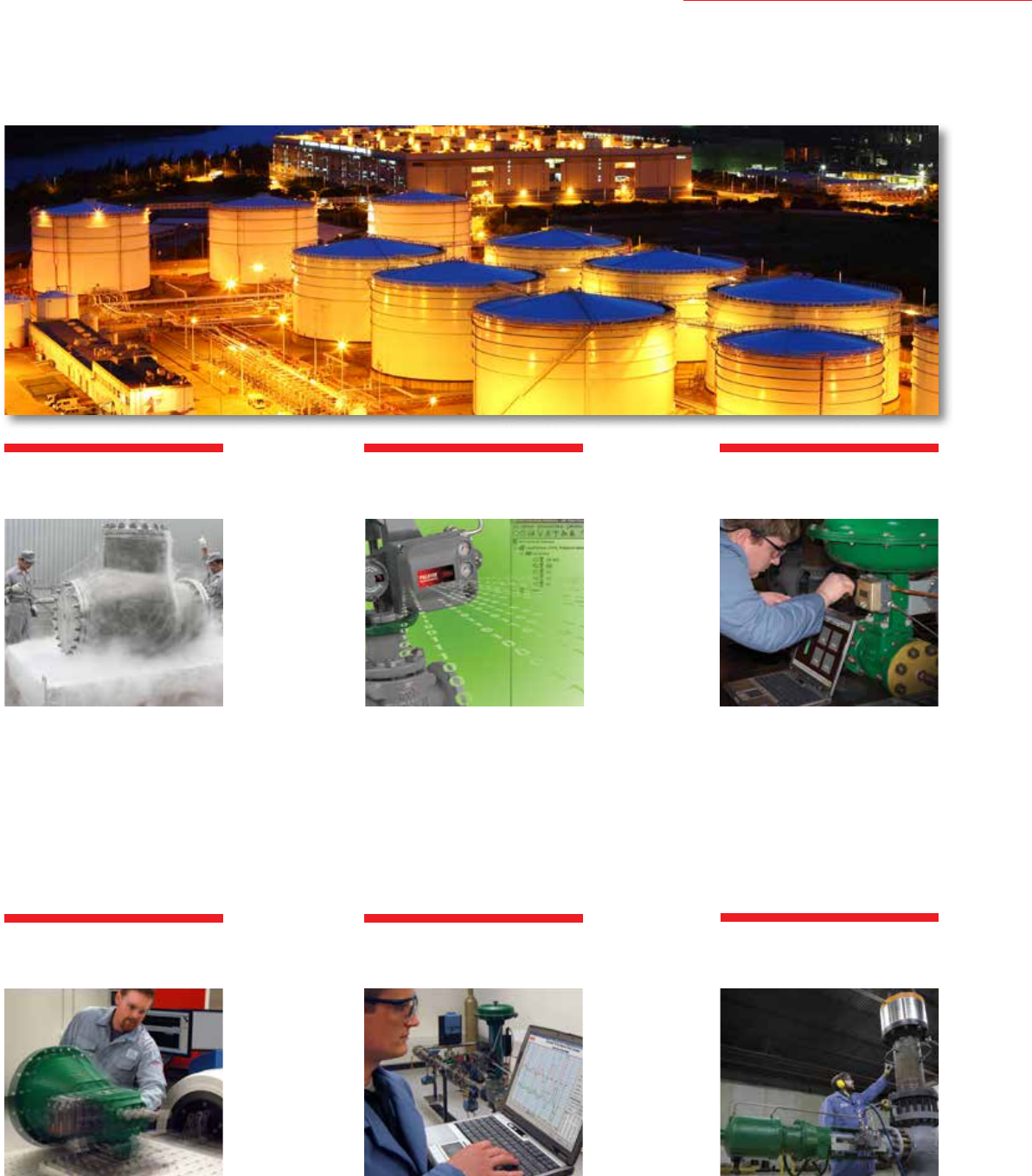
Whether driven by process
temperatures or climate extremes,
control valves need to operate as
specified. Fisher control valves in
LNG applications are commonly
tested at cryogenic temperatures of
-196°C (-321°F) in numerous Fisher
sites around the world.
While control valves are on-line
and in service, Fisher digital
valve controllers can detect,
capture, and trend more than
200 fault conditions and provide
recommended actions to prevent
unexpected downtime.
Many of Emerson’s standard Fisher
products are used in extremely
high-cycle applications, and must
be tested to more than one million
cycles. Those same standard
products are used in your LNG
plant to enhance reliability.
Fisher control valves are designed
and tested for robustness in
vibration applications. They are
subjected to additional testing
for millions of cycles at their
resonant (worst case) frequency
to enhance performance in your
facility.
Fisher control valve assemblies
are subjected to on-line, dynamic
performance testing to evaluate
their ability to reduce your
process variability. These tests
replicate how control valves are
used in your plant.
Supported with a 4,738 m2
(51,000 ft2) facility and a unique
2, 415 m2 (26,000 ft2) sound
chamber, Emerson can quantify
noise from valves, piping, and
vents. This capability provides
insight to ensure highly accurate
noise prediction and helps
you comply with regulatory
requirements.
THRIVING IN EXTREME
TEMPERATURES
TROUBLESHOOTING
CONTROL VALVES
HIGH CYCLE TESTING
WITHSTANDING VIBRATION REDUCING PROCESS
VARIABILITY
QUIETING NOISE
Fisher® LNG Liquefaction Solutions | 23
D352208X012 / (H) MY208 / Jul13
© 2013 Fisher Controls International LLC. All rights reserved.
Fisher, FIELDVUE, WhisperFlo, and Whisper Trim are marks owned by one of the companies in the Emerson Process
Management business unit of Emerson Electric Co. Emerson Process Management, Emerson, and the Emerson
logo are trademarks and service marks of Emerson Electric Co. All other marks are the property of their respective
owners.
The contents of this publication are presented for informational purposes only, and while every
effort has been made to ensure their accuracy, nothing herein is to be construed as a warranty
or guarantee, express or implied, regarding the products or services described herein or their
use, performance, merchantability or fitness for a particular purpose. Individual results may vary.
All sales are governed by our terms and conditions, which are available upon request. We reserve the right
to modify or improve the designs or specications of our products at any time without notice. Responsibility
for proper selection, use and maintenance of any product or service remains solely with the purchaser and
end user.
Emerson Process Management
Marshalltown, Iowa 50158 USA
Sorocaba, 18087 Brazil
Chatham, Kent ME4 4QZ UK
Dubai, United Arab Emirates
Singapore 128461 Singapore
www.Fisher.com
http://www.YouTube.com/user/FisherControlValve
http://www.Twitter.com/FisherValves
http://www.Facebook.com/FisherValves
http://www.LinkedIn.com/groups/Fisher-3941826
main red
PMS 1795C
C0 M96 Y90 K2
YOUTUBE LOGO SPECS
PRINT
gradient bottom
PMS 1815C
C13 M96 Y81 K54
on dark backgroundson light backgrounds
standard
no gradients
watermark
stacked logo (for sharing only)
standard
no gradients
watermark
stacked logo (for sharing only)
white
WHITE
C0 M0 Y0 K0
black
BLACK
C100 M100 Y100 K100
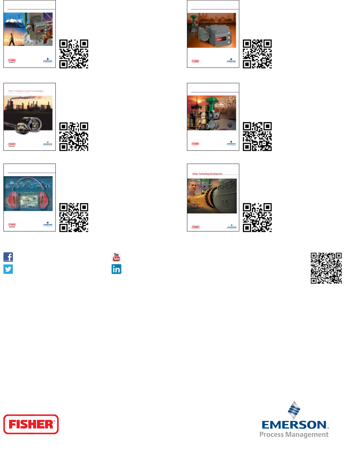
Fisher Optimized Antisurge Control Valves
High reliability to meet world-class production demands
®
“Fisher® Optimized Antisurge Control
Valves Brochure”
Document Number: D351146X012
www.EmersonProcess.com/Fisher/Documentation
“Fisher Cavitation-Control Technologies Brochure”
Document Number: D351912X012
www.EmersonProcess.com/Fisher/Documentation
The Silent Treatment
Fisher® Solutions to Noise Problems
“The Silent Treatment Brochure”
Document Number: D351989X012
www.EmersonProcess.com/Fisher/Documentation
FIELDVUE™ DVC6200 Series Digital Valve Controllers
Higher Process Reliability and Performance
“FIELDVUE™ DVC6200 Series Digital Valve
Controllers Brochure”
Document Number: D351908X012
www.EmersonProcess.com/Fisher/Documentation
Fisher easy-e Sliding-Stem Control Valves
™
®
For easy application and unmatched performance
“Fisher® easy-e™ Sliding-Stem Control
Valves Brochure”
Document Number: D350365X012
www.EmersonProcess.com/Fisher/Documentation
“Emerson Innovation Center Brochure”
Document Number: D351843X012
www.EmersonProcess.com/Fisher/Documentation
If you found this brochure valuable, may we also recommend
the following literature:
To nd the Fisher
sales contact in
your area, scan the
QR code.
