Emerson Fisher Easy E Et Instruction Manual
2015-03-30
: Emerson Emerson-Fisher-Easy-E-Et-Instruction-Manual-680772 emerson-fisher-easy-e-et-instruction-manual-680772 emerson pdf
Open the PDF directly: View PDF ![]() .
.
Page Count: 48
www.Fisher.com
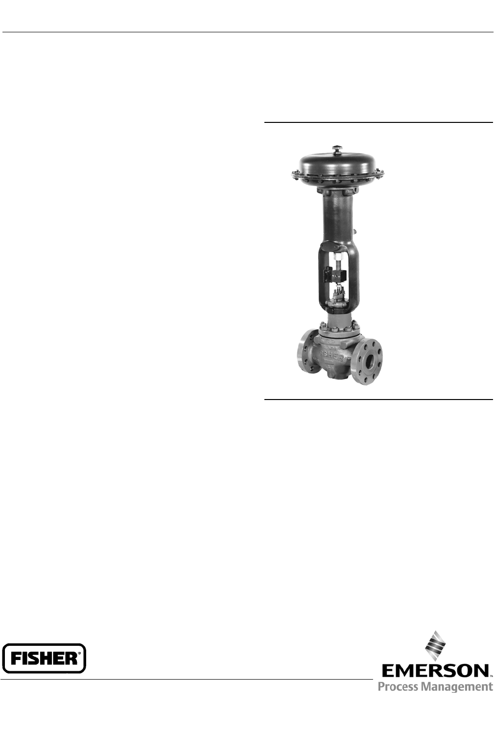
FisherrET and EAT easy-etValves
CL125 through CL600
Contents
Introduction 1...................................
Scope of Manual 1...............................
Description 2...................................
Specifications 3.................................
Educational Services 3...........................
Installation 3....................................
Maintenance 4...................................
Packing Lubrication 5............................
Packing Maintenance 5..........................
Replacing Packing 6.........................
Trim Maintenance 11............................
Disassembly 11.............................
Lapping Metal Seats 12.......................
Valve Plug Maintenance 13....................
Assembly 15................................
ENVIRO-SEALtBellows Seal Bonnet 16.............
Replacing a Plain or Extension Bonnet with an
ENVIRO-SEAL Bellows Seal Bonnet
(Stem/Bellows Assembly) 16................
Replacement of an Installed ENVIRO-SEAL
BellowsSealBonnet(Stem/Bellows
Assembly) 19.............................
Purging the ENVIRO-SEAL Bellows Seal Bonnet 20.
Parts Ordering 21.................................
Parts Kits 21.....................................
Parts List 24.....................................
Figure 1. Fisher ET Control Valve with 667 Actuator
W1916-3
Introduction
Scope of Manual
This instruction manual includes installation, maintenance, and parts information for NPS 1 through 8 Fisher ET valves,
and NPS 1 through 6 EAT valves, through CL600 ratings. Refer to separate manuals for instructions covering the
actuator and accessories.
Do not install, operate, or maintain ET valves without being fully trained and qualified in valve, actuator, and accessory
installation, operation, and maintenance. To avoid personal injury or property damage, it is important to carefully
read, understand, and follow all the contents of this manual, including all safety cautions and warnings. If you have any
questions about these instructions, contact your Emerson Process Management sales office before proceeding.
Instruction Manual
D100398X012
ET Valve
October 2014
Instruction Manual
D100398X012
ET Valve
October 2014
2
Table 1. Specifications
End Connection Styles
Cast Iron Valves
Flanged: CL125 flat-face or 250 raised-face flanges per
ASME B16.1
Steel and Stainless Steel Valves
Flanged: CL150, 300, and 600 raised-face or ring-type
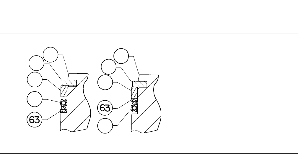
joint flanges per ASME B16.5
Screwed or Socket Welding: All available ASME B16.11
schedules that are consistent with CL600 per ASME
B16.34
Buttwelding: Consistent with ASME B16.25
Maximum Inlet Pressure(1)
Cast Iron Valves
Flanged: Consistent with CL125B or 250B
pressure-temperature ratings per ASME B16.1
Steel and Stainless Steel Valves
Flanged: Consistent with CL150, 300, and 600(2)
pressure-temperature ratings per ASME B16.34
Screwed or Welding: Consistent with CL600
pressure-temperature ratings per ASME B16.34
Shutoff Classifications
See table 2
Flow Characteristics
Linear (all cages), quick-opening (all except Whisper
Trimt,WhisperFlot,andCavitroltcages), or equal
percentage (all except Whisper Trim, WhisperFlo, and
Cavitrol cages)
Flow Directions
Linear, Quick Opening, or Equal Percentage Cage:
Normally down
Whisper Trim and WhisperFlo Cages: Always up
Cavitrol Cage: Always down
Approximate Weights
VALVE SIZE, NPS WEIGHT
kg Pounds
1 and 1-1/4
1-1/2
2
2-1/2
3
4
6
8
14
20
39
45
54
77
159
408
30
45
67
100
125
170
350
900
1. The pressure/temperature limits in this manual and any applicable standard or code limitation for valve should not be exceeded.
2. Certain bonnet bolting material selections may require a CL600 easy-e valve assembly to be derated. Contact your Emerson Process Management sales office.
Table 2. Available Shutoff Classifications per ANSI/FCI 70-2 and IEC 60534-4
Valve Seating Shutoff Class
All except those with Cavitrol III cages
PTFE (standard) V - air test
V - water test (optional)
Metal IV
V (optional)(2)
ET with Cavitrol III one-stage cage Metal IV (standard)
V (optional)
ET with Cavitrol III two-stage cages Metal V
ET w/PEEK Anti-Extrusion Rings Metal Vto316_C (600_F)
ET w/ 3.4375 to 7-inch port Soft or Metal VI
ET and EAT w/ TSO (Tight Shutoff Trim) Replaceable, protected soft seat TSO(1)
1. This is a special non-ANSI/FCI leakage class.
2. Class V shutoff requires spring-loaded seal ring, radiused-seat plug, and wide-bevel seat ring (not available with 8-inch port, quick-opening cage). Not available with trims 4, 29, and 85.
Description
These single-port valves have cage guiding, quick-change trim, and balanced push-down-to-close valve plug action.
Valve configurations are as follows:
ET--Globe-style valve (figure 1) with metal-to-PTFE seating (standard for all except Cavitrol III cages) for stringent
shutoff requirements, or metal-to-metal seating (standard for Cavitrol III cages, optional for all others) for higher
temperatures.

Instruction Manual
D100398X012
ET Valve
October 2014
3
EAT--Angle version of ET, used to facilitate piping or in applications which require a self-draining valve.
Specifications
Typical specifications for these valves are shown in table 1.
Educational Services
For information on available courses for Fisher ET and ETA valves, as well as a variety of other products, contact:
Emerson Process Management
Educational Services - Registration
Phone: 1-641-754-3771 or 1-800-338-8158
E-mail: education@emerson.com
http://www.emersonprocess.com/education
Installation
WARNING
Always wear protective gloves, clothing, and eyewear when performing any installation operations to avoid personal
injury.
Personal injury or equipment damage caused by sudden release of pressure may result if the valve assembly is installed
where service conditions could exceed the limits given in table 1 or on the appropriate nameplates. To avoid such injury or
damage, provide a relief valve for over-pressure protection as required by government or accepted industry codes and
good engineering practices.
Check with your process or safety engineer for any additional measures that must be taken to protect against process
media.
If installing into an existing application, also refer to the WARNING at the beginning of the Maintenance section in this
instruction manual.
CAUTION
When ordered, the valve configuration and construction materials were selected to meet particular pressure, temperature,
pressure drop, and controlled fluid conditions. Responsibility for the safety of process media and compatibility of valve
materials with process media rests solely with the purchaser and end-user. Since some valve body/trim material
combinations are limited in their pressure drop and temperature ranges, do not apply any other conditions to the valve
without first contacting your Emerson Process Management sales office.
Before installing the valve, inspect the valve and pipelines for any damage and any foreign material which may cause
product damage.
1. Before installing the valve, inspect the valve and associated equipment for any damage and any foreign material.
2. Make certain the valve body interior is clean, that pipelines are free of foreign material, and that the valve is
orientedsothatpipelineflowisinthesamedirectionasthearrowonthesideofthevalve.

Instruction Manual
D100398X012
ET Valve
October 2014
4
3. The control valve assembly may be installed in any orientation unless limited by seismic criteria. However, the
normal method is with the actuator vertical above the valve. Other positions may result in uneven valve plug and
cage wear, and improper operation. With some valves, the actuator may also need to be supported when it is not
vertical. For more information, consult your Emerson Process Management sales office.
4. Use accepted piping and welding practices when installing the valve in the line. For flanged valves, use a suitable
gasket between the valve and pipeline flanges.
CAUTION
Depending on valve body materials used, post weld heat treating may be required. If so, damage to internal elastomeric
and plastic parts, as well as internal metal parts is possible. Shrink-fit pieces and threaded connections may also loosen. In
general, if post weld heat treating is to be performed, all trim parts should be removed. Contact your Emerson Process
Management sales office for additional information.
5. With a leak-off bonnet construction, remove the pipe plugs (keys 14 and 16, figure 14) to hook up the leak-off
piping. If continuous operation is required during inspection or maintenance, install a three-valve bypass around
the control valve assembly.
6. If the actuator and valve are shipped separately, refer to the actuator mounting procedure in the appropriate
actuator instruction manual.
WARNING
Personal injury could result from packing leakage. Valve packing was tightened prior to shipment; however, the packing
might require some readjustment to meet specific service conditions. Check with your process or safety engineer for any
additional measures that must be taken to protect against process media.
Valves with ENVIRO-SEAL live-loaded packing or HIGH-SEAL live-loaded packing will not require this initial
readjustment. See the Fisher instruction manuals, ENVIRO-SEAL Packing System for Sliding-Stem Valves or HIGH-SEAL
Live-Loaded Packing System (as appropriate), for packing instructions. If you wish to convert your present packing
arrangement to ENVIRO-SEAL packing, refer to the retrofit kits listed in the Parts Kits section.
Maintenance
Valve parts are subject to normal wear and must be inspected and replaced as necessary. Inspection and maintenance
frequency depends on the severity of service conditions. This section includes instructions for packing lubrication,
packing maintenance, trim maintenance, and ENVIRO-SEAL bellows seal bonnet replacement. All maintenance
operations may be performed with the valve in the line.
WARNING
Avoid personal injury or property damage from sudden release of process pressure or bursting of parts. Before performing
any maintenance operations:
DDo not remove the actuator from the valve while the valve is still pressurized.
DAlways wear protective gloves, clothing, and eyewear when performing any maintenance operations to avoid personal
injury.
DDisconnect any operating lines providing air pressure, electric power, or a control signal to the actuator. Be sure the
actuator cannot suddenly open or close the valve.

Instruction Manual
D100398X012
ET Valve
October 2014
5
DUse bypass valves or completely shut off the process to isolate the valve from process pressure. Relieve process pressure
from both sides of the valve. Drain the process media from both sides of the valve.
DVent the pneumatic actuator loading pressure and relieve any actuator spring precompression.
DUse lock-out procedures to be sure that the above measures stay in effect while you work on the equipment.
DThe valve packing box may contain process fluids that are pressurized, even when the valve has been removed from the
pipeline. Process fluids may spray out under pressure when removing the packing hardware or packing rings, or when
loosening the packing box pipe plug.
DCheck with your process or safety engineer for any additional measures that must be taken to protect against process
media.
CAUTION
Follow instructions carefully to avoid damaging the product surfaces, which could result in damage to the product.
Note
Whenever a gasket seal is disturbed by removing or shifting gasketed parts, install a new gasket during reassembly. This ensures a
good gasket seal because the used gasket may not seal properly.
Packing Lubrication
Note
ENVIRO-SEAL and HIGH-SEAL packing do not require lubrication.
WARNING
To avoid personal injury or property damage resulting from fire or explosion, do not lubricate packing used in oxygen
service or in processes with temperatures over 260_C (500_F).
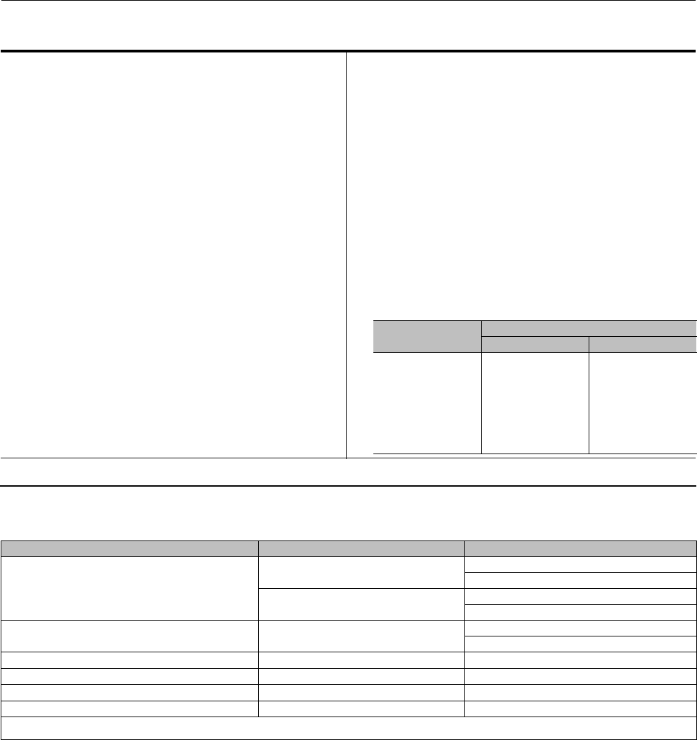
If a lubricator or lubricator/isolating valve (figure 2) is provided for PTFE/composition or other packings that require
lubrication, it will be installed in place of the pipe plug (key 14, figure 14). Use a good quality silicon-base lubricant. Do
not lubricate packing used in oxygen service or in processes with temperatures over 260_C(500_F). To operate the
lubricator, simply turn the cap screw clockwise to force the lubricant into the packing box. The lubricator/isolating
valve operates the same way except open the isolating valve before turning the cap screw and then close the isolating
valve after lubrication is completed.
Packing Maintenance
Note
For valves with ENVIRO-SEAL packing, see the Fisher instruction manual, ENVIRO-SEAL Packing System for Sliding-Stem Valves,
D101642X012, for packing instructions.
Instruction Manual
D100398X012
ET Valve
October 2014
6
For valves with HIGH-SEAL packing, see the Fisher instruction manual, HIGH-SEAL Live-Loaded Packing System,D101453X012, for
packing instructions.
Key numbers refer to figure 3 for PTFE V-ring packing and to figure 4 for PTFE/composition packing, unless otherwise
indicated.
For spring-loaded single PTFE V-ring packing, the spring (key 8) maintains a sealing force on the packing. If leakage is
noted around the packing follower (key 13), check to be sure the shoulder on the packing follower is touching the
bonnet. If the shoulder is not touching the bonnet, tighten the packing flange nuts (key 5, figure 14) until the shoulder
is against the bonnet. If leakage cannot be stopped in this manner, proceed to the Replacing Packing procedure.
Figure 2. Lubricator and Lubricator/Isolating Valve (Optional)
LUBRICATOR
LUBRICATOR/ISOLATING VALVE
10A9421-A
AJ5428-D
A0832-2
If there is undesirable packing leakage with other than spring-loaded packing, first try to limit the leakage and
establish a stem seal by tightening the packing flange nuts.
If the packing is relatively new and tight on the stem, and if tightening the packing flange nuts does not stop the
leakage, the valve stem may be worn or nicked so that a seal cannot be made. The surface finish of a new valve stem is
critical for making a good packing seal. If the leakage comes from the outside diameter of the packing, the leakage
may be caused by nicks or scratches around the packing box wall. If performing any of the following procedures,
inspect the valve stem and packing box wall for nicks and scratches.
Replacing Packing
WARNING
Refer to the WARNING at the beginning of the Maintenance section in this instruction manual.
1. Isolatethecontrolvalvefromthelinepressure,releasepressure from both sides of the valve, and drain the process
media from both sides of the valve. If using a power actuator, also shut off all pressure lines to the power actuator,
andreleaseallpressurefromtheactuator.Uselock-outprocedurestobesurethattheabovemeasuresstayin
effect while you work on the equipment.
2. Disconnect the operating lines from the actuator and any leak-off piping from the bonnet. Disconnect the stem
connector, then remove the actuator from the valve by unscrewing the yoke locknut (key 15, figure 14) or the hex
nuts (key 26, figure 14).
Instruction Manual
D100398X012
ET Valve
October 2014
7
3. Loosen the packing flange nuts (key 5, figure 14) so that the packing is not tight on the valve stem. Remove any
travel indicator parts and stem locknuts from the valve stem threads.
WARNING
To avoid personal injury or property damage caused by uncontrolled movement of the bonnet, loosen the bonnet by
following the instructions in the next step. Do not remove a stuck bonnet by pulling on it with equipment that can stretch
or store energy in any other manner. The sudden release of stored energy can cause uncontrolled movement of the bonnet.
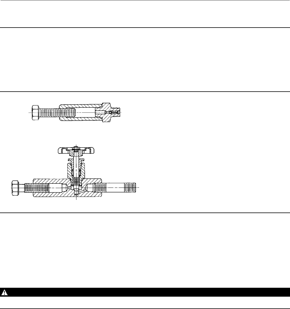
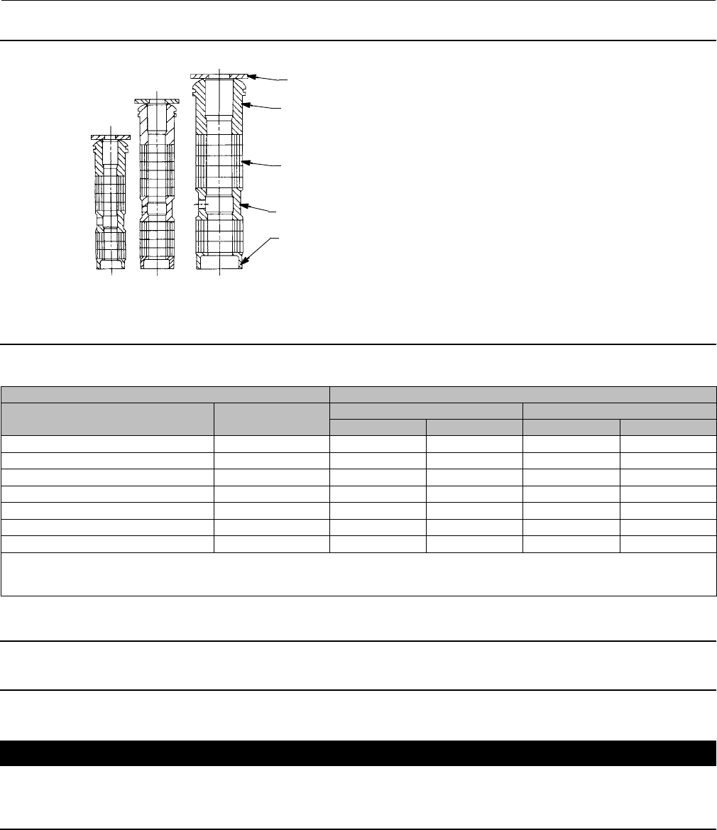
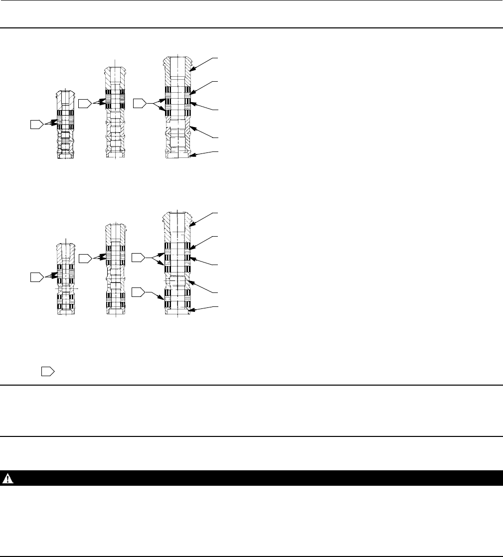
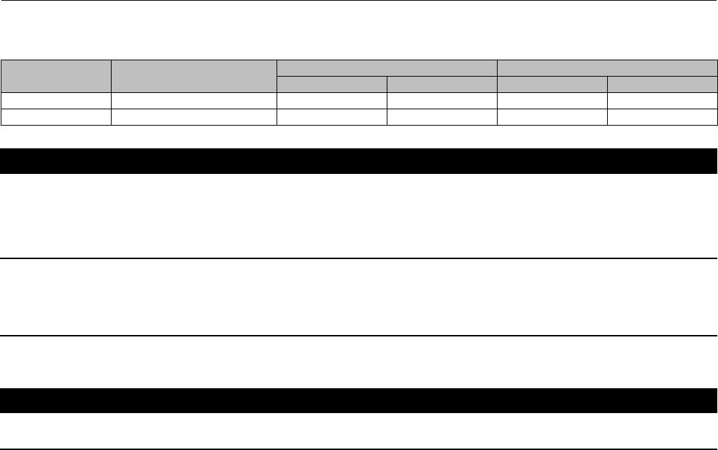
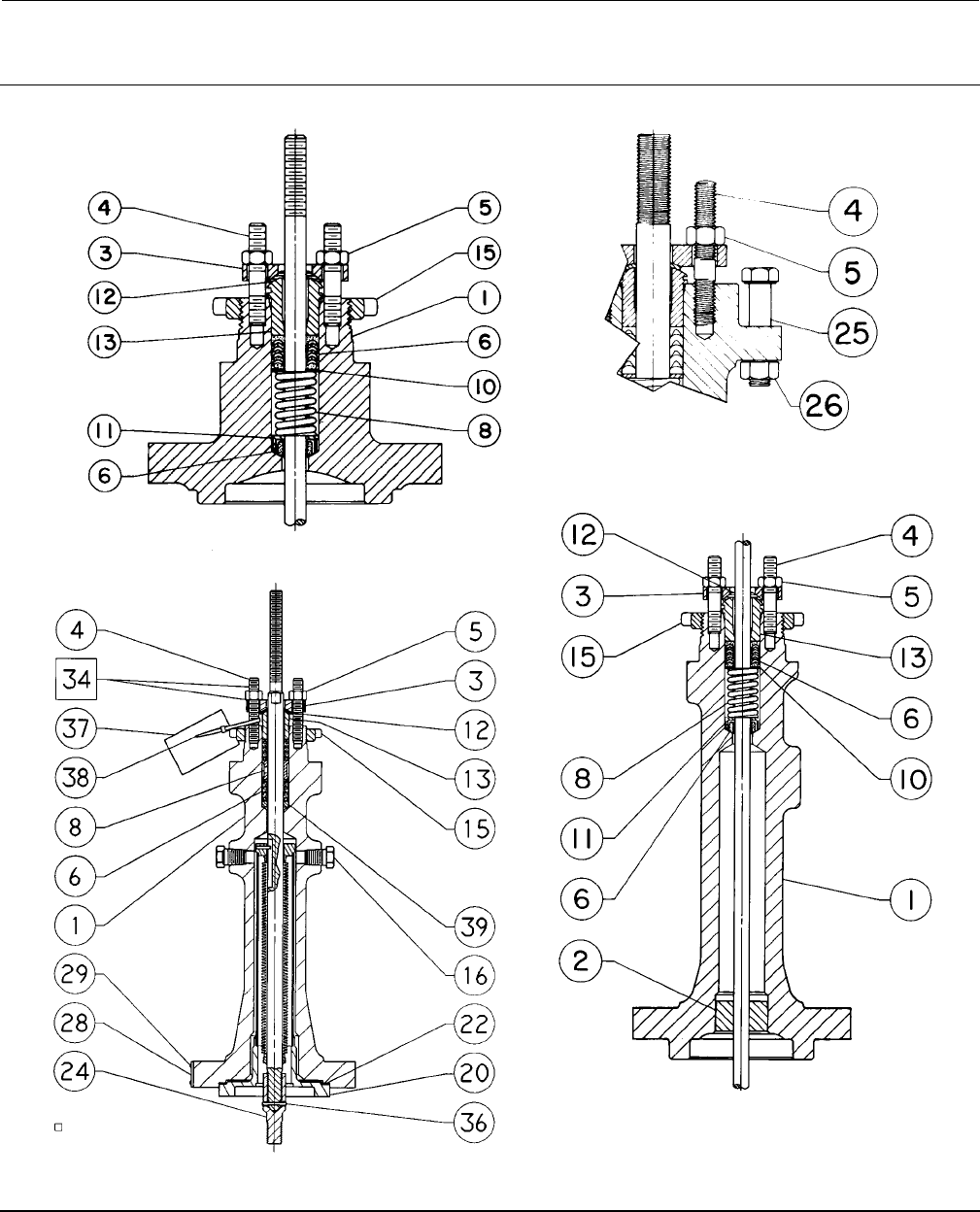
Figure 3. PTFE V-Ring Packing Arrangements for Plain and Extension Bonnets
UPPER WIPER
(KEY 12)
PACKING
FOLLOWER (KEY 13
)
LANTERN RING
(KEY 8)
PACKING BOX
RING (KEY 11)
MALE ADAPTOR
PACKING RING
FEMALE ADAPTOR
LOWER WIPER
ASSEMBLY 1
(POSITIVE
PRESSURES)
ASSEMBLY 2
(VACUUM)
ASSEMBLY 3
(POSITIVE
PRESSURES
& VACUUM)
ASSEMBLY 1
(POSITIVE
PRESSURES)
ASSEMBLY 2
(VACUUM)
ASSEMBLY 3
(POSITIVE
PRESSURES
& VACUUM)
ASSEMBLY 1
(POSITIVE
PRESSURES)
ASSEMBLY 2
(VACUUM)
ASSEMBLY 3
(POSITIVE
PRESSURES
& VACUUM)
9.5 mm (3/8 INCH) STEM 12.7 mm (1/2 INCH) STEM 19.1, 25.4, OR 31.8 mm
(3/4,1,OR1-1/4INCH)STEM
DOUBLE ARRANGEMENTS
A
8187-D 12A7814-D 12A7839-A
B1428-5
UPPER WIPER
(KEY 12)
PACKING
FOLLOWER (KEY 13)
PACKING BOX
RING (KEY 11)
FOR 316 SST
METAL PACKING BOX PARTS
SINGLE ARRANGEMENTS
12A7837-A
B1429-5
FORALLOTHERMETALPACKING
BOX PART MATERIALS
SPACER (KEY 8)
UPPER WIPER
(KEY 12)
PACKING
FOLLOWER
(KEY 13)
PACKING BOX
RING (KEY 11)
FEMALE
ADAPTOR
FEMALE
ADAPTOR
MALE
ADAPTOR
PACKING
RING
MALE
ADAPTOR
PACKING
RING
WASHER
(KEY 10)
SPRING
(KEY 8)
LOWER
WIPER
LOWER
WIPER
1
1
1
1
1
1
1
1
NOTE:
MALE ADAPTOR, PACKING RING, FEMALE ADAPTOR,
AND LOWER WIPER ARE PART OF PACKING SET (KEY 6).
2 REQ'D FOR DOUBLE ARRANGEMENTS, EXCEPT LOWER WIPER.
1
Instruction Manual
D100398X012
ET Valve
October 2014
8
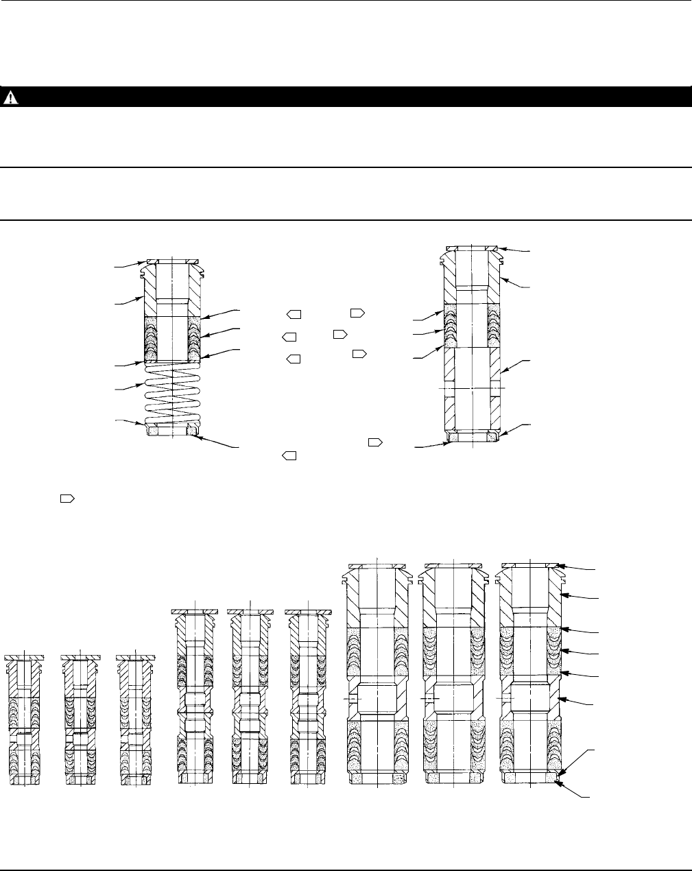
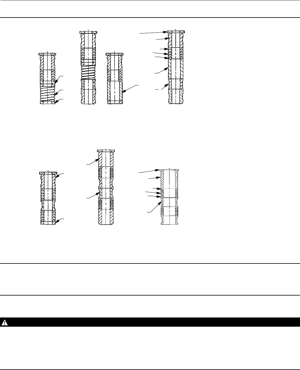
Figure 4. Detail of PTFE/Composition Packing Arrangements for Plain and Extension Bonnets
UPPER WIPER
(KEY 12)
PACKING
FOLLOWER (KEY 13)
LANTERN RING
(KEY 8)
PACKING BOX
RING (KEY 11)
PACKING RING
(KEY 7)
9.5 mm
(3/8 INCH)
STEM
12.7 mm
(1/2 INCH)
STEM
19.1, 25.4, OR
31.8 mm
(3/4,1,OR
1-1/4 INCH)
STEM
12A8188-A
12A7815-A
12A8173-A
A2619-1
Table 3. Body-to-Bonnet Bolt Torque Guidelines
VALVE SIZE, NPS BOLT TORQUES(1)
ET EAT SA193-B7, SA193-B8M(3, 4) SA193-B8M(2, 4)
NSmLbfSft NSmLbfSft
1-1/4 or less 1129 95 64 47
1-1/2, 1-1/2 x 1, 2, or 2 x 1 2or2x1 96 71 45 33
2-1/2 or 2-1/2 x 1-1/2 3or3x1-1/2 129 95 64 47
3, 3 x 2, or 3 x 2-1/2 4or4x2 169 125 88 65
4, 4 x 2-1/2, or 4 x 3 6or6x2-1/2 271 200 156 115
6——— 549 405 366 270
8——— 746 550 529 390
1. Determined from laboratory tests.
2. SA193-B8M annealed.
3. SA193-B8M strain hardened.
4. For other materials, contact your Emerson Process Management sales office.
Note
The following step also helps to provide additional assurance that the valve body fluid pressure has been relieved.
CAUTION
Avoid damaging the seating surface caused by the valve plug and stem assembly dropping from the bonnet (key 1, figure
14) after being lifted part way out. When lifting the bonnet, temporarily install a valve stem locknut on the valve stem. The
locknut will prevent the valve plug and stem assembly from dropping out of the bonnet.
4. Hex nuts (key 16, figure 16, 17, or 20) or cap screws (not shown) attach the bonnet (key 1, figure 14) to the valve
body (key 1, figure 16, 17, or 20). Loosen these nuts or cap screws approximately 3 mm (1/8 inch). Then loosen the
body-to-bonnet gasketed joint by either rocking the bonnet or prying between the bonnet and valve. Work the

Instruction Manual
D100398X012
ET Valve
October 2014
9
prying tool around the bonnet until the bonnet loosens. If no fluid leaks from the joint, remove the nuts or cap
screws completely and carefully lift the bonnet off the valve.
Table 4. Recommended Torque for Packing Flange Nuts
VALVE STEM DIAMETER PRESSURE
RATING
GRAPHITE TYPE PACKING PTFE TYPE PACKING
Minimum Torque Maximum Torque Minimum Torque Maximum Torque
mm Inches NSmLbfSin NSmLbfSin NSmLbfSin NSmLbfSin
9.5 3/8
CL125, 150 327 540 113 219
CL250, 300 436 653 217 326
CL600 649 873 323 435
12.7 1/2
CL125, 150 544 866 221 431
CL250, 300 759 10 88 328 542
CL600 981 14 122 439 758
19.1 3/4
CL125, 150 11 99 17 149 547 870
CL250, 300 15 133 23 199 764 11 95
CL600 21 182 31 274 10 87 15 131
25.4 1CL300 26 226 38 339 12 108 18 162
CL600 35 310 53 466 17 149 25 223
31.8 1-1/4 CL300 36 318 54 477 17 152 26 228
CL600 49 437 74 655 24 209 36 314
5. Remove the locknut and separate the valve plug and stem from the bonnet. Set the parts on a protective surface to
prevent damage to gasket or seating surfaces.
CAUTION
To prevent possible product damage, cover the opening in the valve in the following procedure to prevent foreign material
from getting into the valve body cavity.
6. Remove the bonnet gasket (key 10, figure 16, 17, or 20) and cover the opening in the valve to protect the gasket
surface and prevent foreign material from getting into the valve body cavity.
7. Remove the packing flange nuts, packing flange, upper wiper, and packing follower (keys 5, 3, 12, and 13, figure
14). Carefully push out all the remaining packing parts from the valve side of the bonnet using a rounded rod or
other tool that will not scratch the packing box wall. Clean the packing box and the metal packing parts.
8. Inspect the valve stem threads and packing box surfaces for any sharp edges which might cut the packing.
Scratches or burrs could cause packing box leakage or damage to the new packing. If the surface condition cannot
be improved by light sanding, replace the damaged parts by following the appropriate steps in the Trim
Maintenance procedure.
9. Remove the covering protecting the valve body cavity and install a new bonnet gasket (key 10, figure 16, 17, or 20),
making sure the gasket seating surfaces are clean and smooth. Then slide the bonnet over the stem and onto the
stud bolts (key 15, figure 16, 17, or 20) or onto the valve body cavity if cap screws (not shown) will be used instead.
Note
Proper performance of the bolting procedures in step 10 compresses the spiral wound gasket (key 12, figure 16 or 17) or load ring
(key 26, figure 20) enough to both load and seal the seat ring gasket (key 13, figure 16, 17 or 20). It also compresses the outer
edge of the bonnet gasket (key 10, figure 16 through 20) enough to seal the body-to-bonnet joint.
The proper bolting procedures in step 10 include--but are not limited to--ensuring that bolting threads are clean, and evenly
tightening the cap screws, or the nuts onto the studs, in a crisscross pattern. Tightening one cap screw or nut may loosen an
adjacent cap screw or nut. Repeat the crisscross tightening pattern several times until each cap screw or nut is tight and the
body-to-bonnet seal is made. When the operating temperature has been reached, perform this torquing procedure once again.
Instruction Manual
D100398X012
ET Valve
October 2014
10
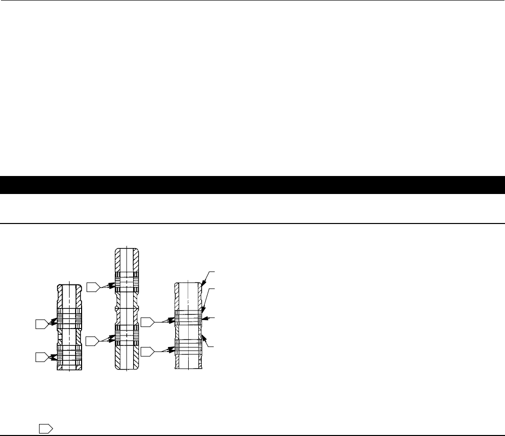
Figure 5. Detail of Graphite Ribbon/Filament Packing for Plain and Extension Bonnets
PACKING FOLLOWER (KEY 13)
LANTERN RING (KEY 8)
PACKING BOX RING (KEY 11)
1
12.7 mm
(1/2 INCH)
STEM
SINGLE ARRANGEMENTS
NOTE:
0.102 mm (0.004 INCH) THICK SACRIFICIAL ZINC WASHERS; USE ONLY ONE BELOW EACH GRAPHITE RIBBON RING.
A5864 1
GRAPHITE RIBBON PACKING RING (KEY 7)
GRAPHITEFILAMENTPACKINGRING(KEY7)
1
1
9.5 mm
(3/8 INCH)
STEM
19.1, 25.4, & 31.8 mm
(3/4, 1 & 1-1/4 INCH)
STEM
14A3411-A 13A9775-B 13A9776-B
PACKINGFOLLOWER(KEY13)
LANTERN RING (KEY 8)
PACKING BOX RING (KEY 11)
1
12.7 mm
(1/2 INCH)
STEM
DOUBLE ARRANGEMENTS
GRAPHITE RIBBON PACKING RING (KEY 7)
GRAPHITE FILAMENT PACKING RING (KEY 7)
1
1
9.5 mm
(3/8 INCH)
STEM
19.1, 25.4, & 31.8 mm
(3/4, 1 & 1-1/4 INCH)
STEM
14A2153-B 14A1849-B 14A1780-B
1
Note
Stud(s) and nut(s) should be installed such that the manufacturer's trademark and material grade marking is visible, allowing easy
comparison to the materials selected and documented in the Emerson/Fisher serial card provided with this product.
WARNING
Personal injury or damage to equipment could occur if improper stud and nut materials or parts are used. Do not operate or
assemble this product with stud(s) and nut(s) that are not approved by Emerson/Fisher engineering and/or listed on the
serial card provided with this product. Use of unapproved materials and parts could lead to stresses exceeding the design
or code limits intended for this particular service. Install studs with the material grade and manufacturer's identification
mark visible. Contact your Emerson Process Management representative immediately if a discrepancy between actual
parts and approved parts is suspected.
10. Lubricate the bolting (not necessary if factory pre-lubricated stud bolt nuts are used) and install it, using accepted
bolting procedures during tightening, so that the body-to-bonnet joint will withstand test pressures and application
service conditions. Use the bolt torques in table 3 as guidelines.
11. Install new packing and the metal packing box parts according to the appropriate arrangement in figure 3, 4, or 5.
Place a smooth-edged pipe over the valve stem and gently tap each soft packing part into the packing box.
Instruction Manual
D100398X012
ET Valve
October 2014
11
12. Slide the packing follower, upper wiper, and packing flange (keys 13, 12, and 3, figure 14) into position. Lubricate
the packing flange studs (key 4, figure 14) and the faces of the packing flange nuts (key 5, figure 14). Install the
packing flange nuts.
13. For spring-loaded PTFE V-ring packing, tighten the packing flange nuts until the shoulder on the packing follower
(key 13, figure 14) contacts the bonnet.
For graphite packing, tighten the packing flange nuts to the maximum recommended torque shown in table 4. Then,
loosen the packing flange nuts, and retighten them to the recommended minimumtorqueshownintable4.
For other packing types, tighten the packing flange nuts alternately in small equal increments until one of the nuts
reaches the minimum recommended torque shown in table 4. Then, tighten the remaining flange nut until the
packing flange is level and at a 90-degree angle to the valve stem.
For ENVIRO-SEAL or HIGH-SEAL live-loaded packing, refer to the note at the beginning of Packing Maintenance.
14. Mount the actuator on the valve assembly and reconnect the actuator and valve stem according to the procedure
in the appropriate actuator instruction manual.
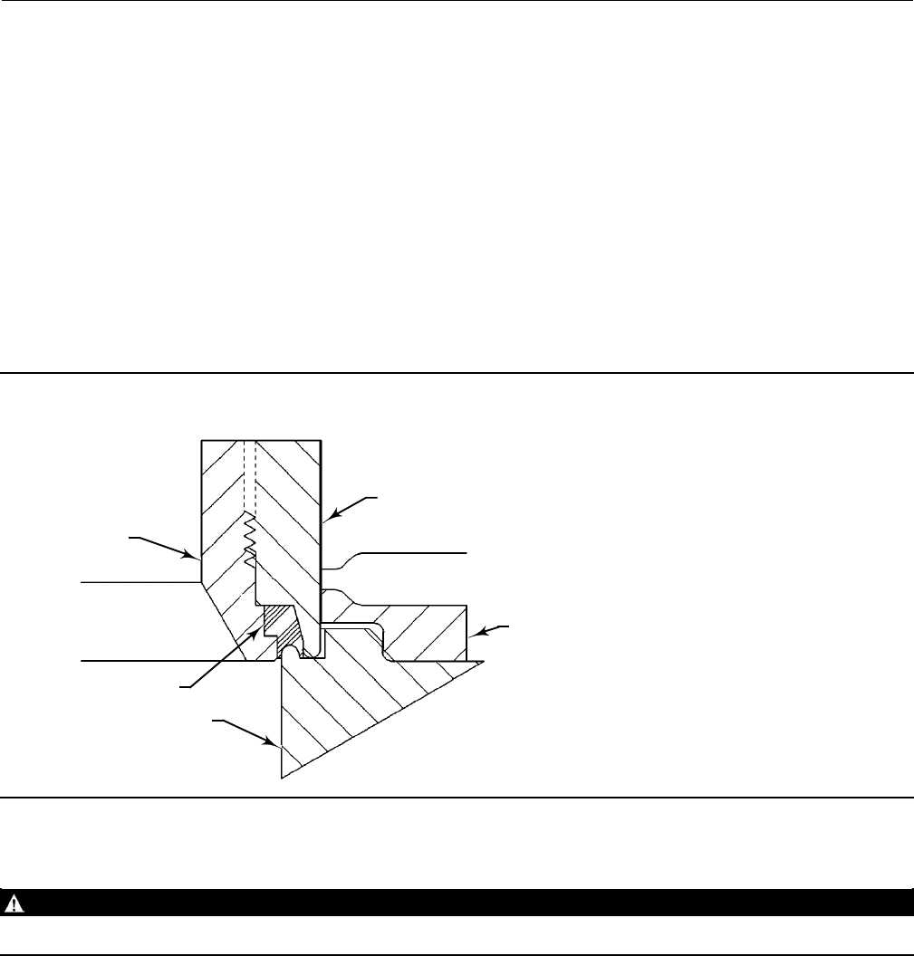
Figure 6. TSO (Tight Shutoff Trim), Detail of Protected Soft Seat
INNER PLUG
OUTER PLUG
CAGE
SEAT RING
PROTECTED SOFT SEAT
A7088
Trim Maintenance
WARNING
Refer to the WARNING at the beginning of the Maintenance section in this instruction manual.
Except where indicated, key numbers in this section are referenced in figure 16 for standard NPS 1 through 6
constructions, figure 17 for Whisper Trim III detail, figures 18 and 19 for WhisperFlo trim, and figure 20 for Cavitrol III
detail and the NPS 8 ET valve.
Disassembly
1. Remove the actuator and the bonnet according to steps 1 through 6 of the Replacing Packing procedure in the
Maintenance section.

Instruction Manual
D100398X012
ET Valve
October 2014
12
WARNING
To avoid personal injury due to leaking fluid, avoid damaging gasket sealing surfaces. The surface finish of the valve stem
(key 7) is critical for making a good packing seal. The inside surface of the cage or cage/baffle assembly (key 3), or cage
retainer (key 31), is critical for smooth operation of the valve plug. The seating surfaces of the valve plug (key 2) and seat
ring (key 9) are critical for proper shutoff. Unless inspection reveals otherwise, assume all these parts are in good condition
and protect them accordingly.
2. Remove the packing flange nuts, packing flange, upper wiper, and packing follower (keys 5, 3, 12, and 13 in figure
14). Carefully push out all the remaining packing parts from the valve side of the bonnet using a rounded rod or
other tool that will not scratch the packing box wall. Clean the packing box and the metal packing parts.
3. Inspect the valve stem threads and packing box surfaces for any sharp edges which might cut the packing.
Scratches or burrs could cause packing box leakage or damage to the new packing. If the surface condition cannot
be improved by light sanding, replace the damaged parts.
4. Remove the load ring (key 26) from an NPS 8 ET valve, or the cage adaptor (key 4) from any restricted-trim valve
throughNPS4,andwrapitforprotection.
5. On an NPS 6 ET valve with Whisper Trim III or WhisperFlo cage, also remove the bonnet spacer (key 32) and bonnet
gasket (key 10) on top of the spacer. Then on any construction with a cage retainer (key 31), remove the cage
retainer and its associated gaskets. A Whisper Trim III and WhisperFlo cage retainer has two 3/8-inch-16 UNC
tappings in which screws or bolts can be installed for lifting.
6. Remove the cage or cage/baffle assembly (key 3), the associated gaskets (keys 10, 11, and 12), and shim (key 51). If
thecageisstuckinthevalve,usearubbermallettostriketheexposedportionofthecageatseveralpointsaround
its circumference.
7. For constructions other than TSO (tight shutoff) trim, remove the seat ring or liner (key 9) or disk seat (key 22), seat
ring gasket (key 13), and the seat ring adaptor (key 5) and adaptor gasket (key 14) where used in a restricted-trim
seat ring construction. PTFE-seat constructions use a disk (key 23) sandwiched between the disk seat and disk
retainer (key 21).
8. For TSO (tight shutoff) trim constructions, perform the following steps (refer to figures 6 and 7):
DRemove the retainer, backup ring, anti-extrusion rings, and piston ring.
DRemove the set screws that lock the outer plug to the inner plug.
DUsing a strap wrench or similar tool, unscrew the outer plug from the inner plug. Do not damage the outer plug
guide surfaces.
DRemove the protected soft seat seal.
DInspect the parts for damage and replace if needed.
9. For all constructions, inspect parts for wear or damage which would prevent proper operation of the valve. Replace
or repair trim parts according to the following procedure for Lapping Metal Seats or other valve plug maintenance
procedures as appropriate.
Lapping Metal Seats
CAUTION
To avoid damaging the ENVIRO-SEAL Bellows Seal Bonnet assembly, do not attempt to lap the metal seating surfaces. The
design of the assembly prevents rotation of the stem and any forced lapping rotation will damage internal components of
the ENVIRO-SEAL Bellows Seal bonnet.
Instruction Manual
D100398X012
ET Valve
October 2014
13
Except with respect to the ENVIRO-SEAL Bellows Seal Bonnet assembly, with metal-seat constructions, lapping seating
surfaces of the valve plug and seat ring or liner (keys 2 and 9, figure 16, 17, or 20) can improve shutoff. (Deep nicks
should be machined out rather than ground out.) Use a good quality lapping compound of a mixture of 280 to
600-grit. Apply the compound to the bottom of the valve plug.
Assemble the valve to the extent that the cage and the cage retainer and bonnet spacer (if used) are in place and the
bonnetisboltedtothevalvebody.Asimplehandlecanbemadefromapieceofstrapironlockedtothevalveplug
stem with nuts. Rotate the handle alternately in each direction to lap the seats. After lapping, remove the bonnet and
clean the seat surfaces. Completely assemble as described in the Assembly portion of the Trim Maintenance procedure
and test the valve for shutoff. Repeat the lapping procedure if leakage is still excessive.
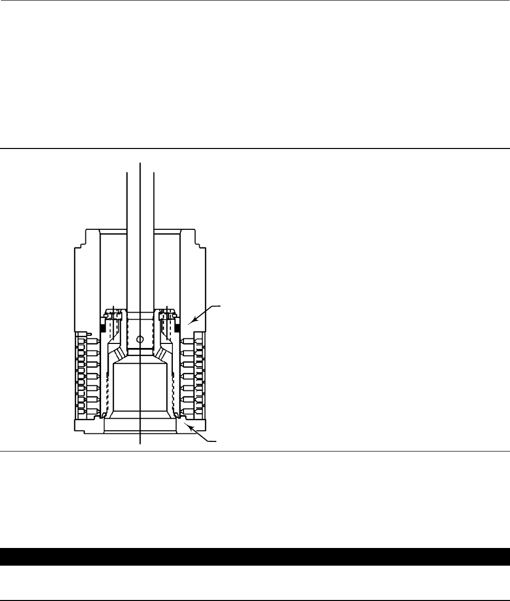
Figure 7. Typical Balanced TSO Trim
VALVE PLUG SEAL
PROTECTED SOFT SEAT
A7096
Valve Plug Maintenance
Except where indicated, key numbers in this section are referenced in figure 16 for standard NPS 1 through 6
constructions, figure 17 for Whisper Trim III, figures 18 and 19 for WhisperFlo trim, and figure 20 for Cavitrol III detail
and the NPS 8 ET valve.
CAUTION
To avoid the valve plug seal ring (key 28) not sealing properly, be careful not to scratch the surfaces of the ring groove in
the valve plug or any of the surfaces of the replacement ring.
1. With the valve plug (key 2) removed according to the Disassembly portion of the Trim Maintenance procedure,
proceed as appropriate:

Instruction Manual
D100398X012
ET Valve
October 2014
14
For the two-piece seal ring, The ring cannot be reused because it is a closed ring which must be pried and/or cut from
the groove. Once the seal ring is removed, the elastomeric backup ring (key 29), which is also a closed ring, can be
pried from the groove.
CAUTION
To avoid damaging the seal ring, slowly and gently stretch it for the following procedure. Avoid jerking sharply on the ring.
To install a new two-piece seal ring, apply a general purpose silicone-base lubricant to both the backup ring and seal
ring(keys29and28).Placethebackupringoverthestem(key7)andintothegroove.Placethesealringoverthetop
edge of the valve plug (key 2) so that it enters the groove on one side of the valve plug. Slowly and gently stretch the
sealringandworkitoverthetopedgeofthevalveplug.ThePTFEmaterialinthesealringmustbepermittedtimeto
cold-flow during the stretching procedure, so avoid jerking sharply on this ring. Stretching the seal ring over the valve
plug may make it seem unduly loose when in the groove, but it will contract to its original size after insertion into the
cage.
For the spring-loaded seal ring, the ring used on a valve plug having a 136.5 mm (5.375 inch) or less port diameter may
be removed undamaged by first working the retaining ring (key 27) off with a screwdriver. Then carefully slide the
metal backup ring (key 29) and seal ring (key 28) off the valve plug (key 2). The spring-loaded seal ring used on a valve
plug having a 178 mm (7-inch) or greater port diameter must be carefully pried and/or cut from its groove. Therefore,
it cannot be reused.
A spring-loaded seal ring must be installed so that its open side faces toward the valve stem, or toward the seat of the
plug depending on flow direction, as shown in view A of figure 16 or 20. To install a spring-loaded seal ring on a valve
plug with a 136.5 mm (5.375 inch) or less port diameter, slide the seal ring (key 28) onto the valve plug followed by
the metal backup ring (key 29). Then install the retaining ring (key 27) by inserting one end in the groove and, while
turning the plug, press the ring into the groove. Again, be careful not to scratch any surfaces of the ring or plug.
CAUTION
To avoid damaging the seal ring, slowly and gently stretch it for the following procedure. Avoid jerking sharply on the ring.
To install the seal ring on a valve plug with 178 mm (7-inch) or greater port diameter, lubricate it with a general
purpose silicone-base lubricant. Then gently stretch the seal ring and work it over the top edge of the valve plug. The
PTFE material in the seal ring must be permitted time to cold-flow during the stretching procedure, so avoid jerking
sharply on the ring. Stretching the seal ring over the valve plug may make it seem unduly loose when in the groove,
but it will contract to its original size after insertion into the cage.
CAUTION
Never reuse an old stem or adaptor with a new valve plug. Using an old stem or adaptor with a new plug requires drilling a
new pin hole in the stem (or adaptor, in case an ENVIRO-SEAL bellows seal bonnet is being used). This drilling weakens the
stem or adaptor and may cause failure in service. However, a used valve plug may be reused with a new stem or adaptor,
except with Cavitrol III trim.
Note
The valve plug and valve plug stem for 2-stage Cavitrol III trim are a matched set and must be ordered together. If the 2-stage
Cavitrol III valve plug or valve plug stem is damaged, replace the entire assembly (key 2, figure 20).

Instruction Manual
D100398X012
ET Valve
October 2014
15
Note
For plain bonnets and style 1 extension bonnets, the valve plug (key 2), valve stem (key 7), and pin (key 8) are available completely
assembled. Refer to the Key 2, 7, and 8 Valve Plug and Stem Assembly tables in the Parts List.
2. Toreplacethevalvestem(key7),driveoutthepin(key8).Unscrewthevalveplugfromthestemoradaptor.
3. To replace the adaptor (key 24, figure 14) on ENVIRO-SEAL bellows seal bonnets, place the plug stem assembly and
valve plug in a soft-jaw chuck or other type of vise so that the jaws grip a portion of the valve plug that is not a
seating surface. Drive out the pin (key 36, figure 14). Reverse the plug stem assembly in the soft-jaw chuck or vise.
Grip the flat areas on the valve stem just below the threads for the actuator/stem connection. Unscrew the valve
plug/adaptor assembly (key 24, figure 14) from the valve stem assembly (key 20, figure 14).
4. Screw the new stem or adaptor into the valve plug. Tighten to the torque value given in table 5. Refer to table 5 to
select the proper hole size. Drill through the stem or adaptor, using the hole in the valve plug as a guide. Remove
any chips or burrs and drive in a new pin to lock the assembly.
Table 5. Valve Stem Connection Assembly Torque and Pin Replacement
VALVE STEM DIAMETER TORQUE, MINIMUM TO MAXIMUM HOLE SIZE
mm Inches NSmLbfSft mm Inch
9.5
12.7
19.1
25.4
31.8
3/8
1/2
3/4
1
1-1/4
40-47
81-115
237-339
420-481
827-908
25-35
60-85
175-250
310-355
610-670
2.41 - 2.46
3.20 - 3.25
4.80 - 4.88
6.38 - 6.45
6.38 - 6.45
0.095 - 0.097
0.126 - 0.128
0.189 - 0.192
0.251 - 0.254
0.251 - 0.254
5. For ENVIRO-SEAL bellows seal bonnets, grip the flats of the stem extending out of the top of the bellows shroud
with a soft-jaw chuck or other type of vise. Screw the valve plug/adaptor assembly onto the valve stem. Tighten as
necessarytoalignthepinholeinthestemwithoneoftheholesintheadaptor.Securetheadaptortothestemwith
anewpin.
Assembly
Except where indicated, key numbers are referenced in figure 16 for standard NPS 1 through 6 constructions, figure 17
for Whisper Trim III detail, figures 18 and 19 for WhisperFlo detail, and figure 20 for Cavitrol III detail and the NPS 8 ET
valve.
1. With a restricted-trim seat ring construction, install the adaptor gasket (key 14) and seat ring adaptor (key 5).
2. Install the seat ring gasket (key 13), seat ring or liner (key 9), or disk seat (key 22). With a PTFE-seat construction,
install the disk and disk retainer (keys 21 and 23).
3. Install the cage or cage/baffle assembly (key 3). Any rotational orientation of the cage or assembly with respect to
the valve body is acceptable. A Whisper Trim III cage designated by level A3, B3, or C3 may be installed with either
end up. The level D3 cage/baffle assembly or Cavitrol III cage assembly, however, must be installed with the hole
pattern end next to the seat ring. If a cage retainer (key 31) is to be used, place it on top of the cage.
4. For constructions other than TSO (tight shutoff) trim, slide the valve plug (key 2) and stem assembly, or valve plug
and ENVIRO-SEAL bellows seal assembly, into the cage. Make sure the seal ring (key 28) is evenly engaged in the
entrance chamfer at the top of the cage (key 3) or cage retainer (key 31) to avoid damaging the ring.
5. For TSO (tight shutoff) trim constructions, perform the following steps (refer to figures 6 and 7).
DThread the outer plug onto the inner plug until the parts seat metal to metal, using a strap wrench or similar tool
that will not damage the outer plug guide surfaces.
DMark the top of the inner plug and outer plug with alignment marks in the assembled position.

Instruction Manual
D100398X012
ET Valve
October 2014
16
DDisassemble the outer plug from the inner plug and install the seal over the inner plug, so that the seal rests below
the threaded area.
DThread the outer plug onto the inner plug and tighten with a strap wrench or similar tool until the alignment marks
line up. This will ensure that the plug parts are metal to metal and the seal is compressed properly. Do not damage
the outer plug guide surfaces.
DInstall set screws centering the inner plug in the outer plug and torque to 11 NSm(8lbfSft).
DAssemble the piston ring, anti-extrusion rings, backup ring, and retainer.
6. For all constructions, place the gaskets (keys 12, 11 or 14 if used, and 10) and the shim (key 51) on top of the cage
or cage retainer. If there is a cage adaptor (key 4) or a bonnet spacer (key 32), set it on the cage or cage retainer
gaskets and place another flat sheet gasket (key 10) on top of the adaptor or spacer. If there is only a cage retainer,
place another flat sheet gasket on the retainer.
7. With an NPS 8 ET valve, install the load ring (key 26).
8. Mount the bonnet on the valve body and complete assembly according to steps 10 through 14 of the Replacing
Packingprocedure.Besuretoobservethenotepriortostep10.
ENVIRO-SEAL Bellows Seal Bonnet
Replacing a Plain or Extension Bonnet with an ENVIRO-SEAL Bellows Seal Bonnet
(Stem/Bellows Assembly)
1. Remove the actuator and bonnet according to steps 1 through 5 of the Replacing Packing procedure in the
Maintenance section.
2. With care, remove the valve plug and stem assembly from the valve body. If necessary, also lift out the cage.
CAUTION
To prevent possible product damage, cover the opening in the valve in the following procedure to protect the sealing
surfaces and to prevent foreign material from getting into the valve body cavity.
3. Remove and discard the existing bonnet gasket. Cover the valve body opening to protect sealing surfaces and to
prevent foreign material from entering the valve body cavity.
Note
The ENVIRO-SEAL stem/bellows assembly for easy-e valves is available only with a threaded and drilled plug/adaptor/stem
connection. The existing valve plug can be reused with the new stem/bellows assembly or a new plug can be installed.
4. Inspect the existing valve plug. If the plug is in good condition, it can be reused with the new ENVIRO-SEAL
stem/bellows assembly. To remove the existing valve plug from the stem, first, place the existing plug stem
assembly and valve plug in a soft-jaw chuck or other type of vise so that the jaws grip a portion of the valve plug that
is not a seating surface. Drive out or drill out the pin (key 8).
5. Reversetheplugstemassemblyinthesoft-jawchuckorvise.Gripthevalvesteminanappropriateplaceand
unscrew the existing plug from the valve stem.
Instruction Manual
D100398X012
ET Valve
October 2014
17
Table 6. Recommended Torque for ENVIRO-SEAL Bellows Seal Packing Flange Nuts
VALVE SIZE, NPS VALVE STEM DIAMETER
THROUGH PACKING
MINIMUM TORQUE MAXIMUM TORQUE
NSmLbfSin NSmLbfSin
1-2 1/2 222 433
3-8 1 5 44 867
CAUTION
When installing a valve plug on the ENVIRO-SEAL stem/bellows assembly, the valve stem must not be rotated. Damage to
the bellows may result.
To avoid product damage, do not grip the bellows shroud or other parts of the stem/bellows assembly. Grip only the flat
areas on the stem where it extends out of the top of the bellows shroud.
Note
The ENVIRO-SEAL stem/bellows assembly has a one-piece stem.
CAUTION
To avoid damaging parts, do not grip the valve plug on any seating surface in the following procedure.
6. To attach the valve plug to the stem of the new ENVIRO-SEAL stem/bellows assembly, first attach the plug to the
adaptor (key 24). Locate the adaptor. Notice that a hole has not been drilled in the threads where the plug screws
onto the adaptor. Secure the valve plug in a soft-jaw chuck or other type of vise. Do not grip the plug on any seating
surface. Position the plug in the chuck or vise for easy threading of the adaptor. Thread the adaptor into the valve
plug and tighten to the appropriate torque value.
7. Select the proper size of drill bit and drill through the adaptor using the hole in the valve plug as a guide. Remove
any metal chips or burrs and drive in a new pin to lock the plug/adaptor assembly together.
8. Attach the plug/adaptor assembly to the ENVIRO-SEAL stem/bellows assembly by first securing the stem/bellows
assemblyinasoft-jawchuckorothertypeofvisesothatthejawsofthechuckorvisegriptheflatsofthestem
extendingoutofthetopofthebellowsshroud.Screwthevalveplug/adaptorassemblyontothevalvestem.
Tightenasnecessarytoalignthepinholeinthestemwithoneoftheholesintheadaptor.Securetheadaptortothe
stem with a new pin.
9. Inspect the seat ring (key 9) and soft seat parts (keys 21, 22, and 23); replace, if necessary.
10. Place a new gasket (key 10) into the valve body in place of the bonnet gasket. Install the new stem/bellows
assembly with valve plug/adaptor by placing it into the valve body on top of the new bellows gasket.
11. Place a new gasket (key 22) over the stem/bellows assembly. Place the new ENVIRO-SEAL bonnet over the
stem/bellows assembly.
Instruction Manual
D100398X012
ET Valve
October 2014
18
Figure 8. PTFE Packing Arrangements for Use in ENVIRO-SEAL Bellows Seal Bonnets
UPPER WIPER
(KEY 12)
PACKING SET: (KEY 6)
FEMALE ADAPTOR
PACKING RING
MALE ADAPTOR
BUSHING (KEY 13)
9.5 mm
(3/8 INCH)
STEM
12.7 mm
(1/2 INCH)
STEM
DOUBLE ARRANGEMENTS
9.5 mm
(3/8 INCH)
STEM
9.5 mm
(3/8 INCH)
STEM
12.7 mm
(1/2 INCH)
STEM FOR
NPS 2 VALVES
12.7 mm
(1/2 INCH)
STEM FOR
NPS 3 AND 4
VALVES
THRUST
RING
(KEY 39)
SPRING
(KEY 8)
THRUST
RING
(KEY 39)
THRUST
RING
(KEY 39)
BUSHING
(KEY 13)
BUSHING
(KEY 13)
SPACER
(KEY 8)
SPACER
(KEY 8)
SPACER
(KEY 8)
12.7 mm
(1/2 INCH)
STEM
SINGLE ARRANGEMENTS
FOR S31600 (316 SST)
PACKING BOX PARTS
FOR ALL PACKING BOX
MATERIALS EXCEPT S31600
UPPER WIPER
(KEY 12)
PACKING SET: (KEY 6)
FEMALE ADAPTOR
PACKING RING
MALE ADAPTOR
BUSHING (KEY 13)
SPACER
(KEY 8)
A5863
12B4183-A 18A0906-D 18A5338-A
12B4182-A SHT 1 12B4185-A SHT 1 12B4182-A SHT 2 12B4185-A SHT 2
Note
Stud(s) and nut(s) should be installed such that the manufacturer's trademark and material grade marking is visible, allowing easy
comparison to the materials selected and documented in the Emerson/Fisher serial card provided with this product.
WARNING
Personal injury or damage to equipment could occur if improper stud and nut materials or parts are used. Do not operate or
assemble this product with stud(s) and nut(s) that are not approved by Emerson/Fisher engineering and/or listed on the
serial card provided with this product. Use of unapproved materials and parts could lead to stresses exceeding the design
or code limits intended for this particular service. Install studs with the material grade and manufacturer's identification
mark visible. Contact your Emerson Process Management representative immediately if a discrepancy between actual
parts and approved parts is suspected.

Instruction Manual
D100398X012
ET Valve
October 2014
19
12. Properly lubricate the bonnet stud bolts. Install and tighten the bonnet hex nuts to the proper torque.
13. Install new packing and the metal packing box parts according to the appropriate arrangement in figure 8 or 9.
14. Install the packing flange. Properly lubricate the packing flange stud bolts and the faces of the packing flange nuts.
For graphite packing, tighten the packing flange nuts to the maximum recommended torque shown in table 6. Then,
loosen the packing flange nuts, and retighten them to the recommended minimumtorqueshownintable6.
For other packing types, tighten the packing flange nuts alternately in small equal increments until one of the nuts
reaches the minimum recommended torque shown in table 6. Then, tighten the remaining flange nut until the
packing flange is level and at a 90-degree angle to the valve stem.
15. Install travel indicator parts and stem locknuts; mount the actuator on the valve body according to the procedure
in the appropriate actuator instruction manual.
Replacement of an Installed ENVIRO-SEAL Bellows Seal Bonnet (Stem/Bellows Assembly)
1. Remove the actuator and bonnet according to steps 1 through 5 of the Replacing Packing procedure in the
Maintenance section.
CAUTION
To prevent possible product damage, cover the opening in the valve in the following procedure to protect the sealing
surfaces and to prevent foreign material from getting into the valve body cavity.
2. Carefully remove the ENVIRO-SEAL stem/bellows assembly. If necessary, also lift out the cage. Remove and discard
the existing bonnet gasket and bellows gasket. Cover the valve body opening to protect sealing surfaces and to
prevent foreign material from entering the valve body cavity.
CAUTION
The ENVIRO-SEAL stem/bellows assembly for easy-e valves is available only with a threaded and drilled plug/adaptor/stem
connection. The existing valve plug can be reused with the new stem/bellows assembly or a new plug can be installed. If
the existing valve plug is reused, and the adaptor is in good condition, it may be also reused. However, never reuse an old
adaptor with a new valve plug. Using an old adaptor with a new valve plug requires drilling a new pin hole in the adaptor.
This drilling weakens the adaptor and may cause failure in service. However, a used valve plug may be reused with a new
adaptor, except with Cavitrol III trim.
3. Inspect the existing valve plug and adaptor. If they are in good condition, they can be reused with the new
stem/bellows assembly and they do not need to be separated.
CAUTION
When removing/installing a valve plug on the ENVIRO-SEAL stem/bellows assembly, the valve stem must not be rotated.
Damage to the bellows may result.
To avoid product damage, do not grip the bellows shroud or other parts of the stem/bellows assembly. Grip only the flat
areas on the stem where it extends out of the top of the bellows shroud.
Note
The ENVIRO-SEAL stem/bellows assembly has a one-piece stem.
Instruction Manual
D100398X012
ET Valve
October 2014
20
4. If the valve plug and adaptor are not in good condition and must be replaced, first remove the valve plug/adaptor
assemblyfromthestem/bellowsassembly;thenremovethevalveplugfromtheadaptor.First,placethe
stem/bellows assembly and valve plug in a soft-jaw chuck or other type of vise so that the jaws grip a portion of the
valve plug that is not a seating surface. Drive out or drill out the pin (key 8, figure 16, 17, or 20). Drive out the pin
(key 36, figure 14).
5. Reverse the stem/bellows and plug/adaptor assembly in the soft-jaw chuck or vise. Grip the flat areas on the valve
stem just below the threads for the actuator/stem connection. Unscrew the plug/adaptor assembly from the
stem/bellows assembly. Unscrew the valve plug from the adaptor.
6. To attach either the existing valve plug or a new one to the stem of the new ENVIRO-SEAL stem/bellows assembly,
first attach the plug to the adaptor (if the valve plug was removed from the adaptor) as follows:
DLocate the adaptor. Notice that a hole has not been drilled in the threads where the plug screws onto the adaptor.
CAUTION
To avoid damaging parts, do not grip the valve plug on any seating surface in the following procedure.
Figure 9. Double Graphite Ribbon/Filament Arrangements for Use in ENVIRO-SEAL Bellows Seal Bonnets
BUSHING (KEY 13)
SPACER (KEY 8)
1
GRAPHITE FILAMENT PACKING RING (KEY 7)
GRAPHITE RIBBON PACKING RING (KEY 7)
12B6102-A
18A0909-D
12B4181-A
12.7 mm
(1/2 INCH)
STEM FOR
NPS 2 VALVES
9.5 mm
(3/8 INCH)
STEM
12.7 mm
(1/2 INCH)
STEM FOR
NPS 3 AND 4 VALVES
1
1
1
1
1
NOTE:
0.102 mm (0.004 INCH) THICK SACRIFICIAL ZINC WASHERS; USE ONLY ONE BELOW EACH GRAPHITE RIBBON RING.
A5870 1
DSecure the valve plug in a soft-jaw chuck or other type of vise. Do not grip the plug on any seating surface. Position
the plug in the chuck or vise for easy threading of the adaptor.
DThread the adaptor into the valve plug and tighten to the appropriate torque value.
7. Complete the installation by following steps 7 through 9 and steps 12 through 15 of the ENVIRO-SEAL Bellows Seal
Bonnet installation instructions found on pages 14 and 15.
Purging the ENVIRO-SEAL Bellows Seal Bonnet
The ENVIRO-SEAL bellows seal bonnet can be purged or leak tested. Refer to figure 14 for an illustration of an
ENVIRO-SEAL bellows seal bonnet, and perform the following steps for purging or leak testing.
1. Remove the two diametrically opposed pipe plugs (key 16).
2. Connect a purging fluid to one of the pipe plug connections.
3. Install appropriate piping or tubing in the other pipe plug connection to pipe away the purging fluid or to make a
connection to an analyzer for leak testing.

Instruction Manual
D100398X012
ET Valve
October 2014
21
4. When purging or leak testing has been completed, remove the piping or tubing and reinstall the pipe plugs (key
16).
Table 7. Standard Material Designations
Standard Designation Common Name or Tradename
CoCr-A Hardfacing Alloy
R30006
S17400 SST
S31600 SST
CoCr-A
Alloy 6 Casting
17-4PH Stainless Steel
316 Stainless Steel
S41000 SST
S41600 SST
WCC Carbon Steel Casting
410 Stainless Steel
416 Stainless Steel
WCC
Parts Ordering
Each body-bonnet assembly is assigned a serial number which can be found on the valve. This same number also
appears on the actuator nameplate when the valve is shipped from the factory as part of a control valve assembly.
Refer to the serial number when contacting your Emerson Process Management sales office for technical assistance.
When ordering replacement parts, refer to the serial number and to the eleven-character part number for each part
required from the following parts kit or parts list information.
Refer to table 7 for standard and common material designations.
WARNING
Use only genuine Fisher replacement parts. Components that are not supplied by Emerson Process Management should
not, under any circumstances, be used in any Fisher valve, because they may void your warranty, might adversely affect the
performance of the valve, and could cause personal injury and property damage.
Parts Kits
Gasket Kits
Gasket Kits (includes keys 10, 11, 12, 13, and 51; plus 14 and 20 on some restricted capacity valves)
DESCRIPTION
Standard Trim Cage
Whisper Trim I Cage
Cavitrol III - 1 Stage Cage
Cavitrol III - 2 Stage Cage
Whisper Trim III Cage
WhisperFlo Cage
-198 to 593_C (-325 to 1100_F) -198 to 593_C (-325 to 1100_F)
Full Capacity Valves Part Number Part Number
NPS 1 & 1-1/4
NPS 1-1/2 (NPS 2 EAT)
NPS 2
NPS 2-1/2 (NPS 3 EAT)
NPS 3 (NPS 4 EAT)
NPS 4 (NPS 6 EAT)
NPS 6
NPS 8
RGASKETX162
RGASKETX172
RGASKETX182
RGASKETX192
RGASKETX202
RGASKETX212
RGASKETX222
RGASKETX232
RGASKETX422
RGASKETX432
RGASKETX442
RGASKETX452
RGASKETX462
RGASKETX472
RGASKETX482
10A3265X152
Restricted Capacity Valves w/ Metal Seating
NPS1-1/2x1(NPS2x1EAT)
NPS 2 x 1
NPS 2-1/2 x 1-1/2 (NPS 3 x 1-1/2 EAT)
NPS3x2(NPS4x2EAT)
NPS 4 x 2-1/2 (NPS 6 x 2-1/2 EAT)
RGASKETX242
RGASKETX252
RGASKETX262
RGASKETX272
RGASKETX282
---
---
---
---
---

Instruction Manual
D100398X012
ET Valve
October 2014
22
Packing Kits
Standard Packing Repair Kits (Non Live-Loaded)
Standard Packing Repair Kits (Non Live-Loaded)
Stem Diameter, mm (Inches)
Yoke Boss Diameter, mm (Inches)
9.5 (3/8)
54 (2-1/8)
12.7 (1/2)
71 (2-13/16)
19.1 (3/4)
90 (3-9/16)
25.4 (1)
127 (5)
31.8 (1-1/4)
127 (5, 5H)
PTFE (Contains keys 6, 8, 10, 11, and 12) RPACKX00012 RPACKX00022 RPACKX00032 RPACKX00342 RPACKX00352
Double PTFE (Contains keys 6, 8, 11, and 12) RPACKX00042 RPACKX00052 RPACKX00062 RPACKX00362 RPACKX00372
PTFE/Composition (Contains keys 7, 8, 11, and 12) RPACKX00072 RPACKX00082 RPACKX00092 --- ---
Single Graphite Ribbon/Filament (Contains keys 7 [ribbon ring],
7 [filament ring], 8, and 11) RPACKX00102 RPACKX00112 RPACKX00122 --- ---
Single Graphite Ribbon/Filament (Contains keys 7 [ribbon ring],
7 [filament ring], and 11) --- --- --- RPACKX00532 RPACKX00542
Single Graphite Ribbon/Filament (Contains keys 7 [ribbon ring],
7 [filament ring]) RPACKX00132 RPACKX00142 RPACKX00152 --- ---
Double Graphite Ribbon/Filament (Contains keys 7 [ribbon ring],
7 [filament ring], 8, and 11) RPACKX00162 RPACKX00172 RPACKX00182 --- ---
ENVIRO-SEAL Packing Retrofit Kits
Retrofit kits include parts to convert valves with existing standard bonnets to the ENVIRO-SEAL packing box
construction. Refer to figure 11 for key numbers for PTFE packing, to figure 12 for key numbers for Graphite ULF
packing, and to figure 13 for key numbers for duplex packing. PTFE kits include keys 200, 201, 211, 212, 214, 215,
216, 217, 218, tag, and cable tie. Graphite ULF kits include keys 200, 201, 207, 208, 209, 210, 211, 212, 214, 217, tag,
and cable tie. Duplex kits include keys 200, 201, 207, 209, 211, 212, 214, 215, 216, 217, tag, and cable tie.
Stems and packing box constructions that do not meet Emerson Process Management stem finish specifications,
dimensional tolerances, and design specifications, may adversely alter the performance of this packing kit.
For part numbers of individual components in the ENVIRO-SEAL packing kits, refer to instruction manual ENVIRO-SEAL
Packing System for Sliding-Stem Valves, D101642X012.
ENVIRO-SEAL Packing Retrofit Kits
PACKING
MATERIAL
STEM DIAMETER AND YOKE BOSS DIAMETER, mm (INCH)
9.5 (3/8)
54 (2-1/8)
12.7 (1/2)
71 (2-13/16)
19.1 (3/4)
90 (3-9/16)
25.4 (1)
127 (5)
31.8 (1-1/4)
127 (5, 5H)
Double PTFE RPACKXRT012 RPACKXRT022 RPACKXRT032 RPACKXRT042 RPACKXRT052
Graphite ULF RPACKXRT262 RPACKXRT272 RPACKXRT282 RPACKXRT292 RPACKXRT302
Duplex RPACKXRT212 RPACKXRT222 RPACKXRT232 RPACKXRT242 RPACKXRT252
ENVIRO-SEAL Packing Repair Kits
Repair kits include parts to replace the “soft” packing materials in valves that already have ENVIRO-SEAL packing
arrangements installed or in valves that have been upgraded with ENVIRO-SEAL retrofit kits. Refer to figure 11 for key
numbers for PTFE packing, to figure 12 for key numbers for Graphite ULF packing, and to figure 13 for key numbers for
duplex packing. PTFE repair kits include keys 214, 215, and 218. Graphite ULF repair kits include keys 207, 208, 209,
210, and 214. Duplex repair kits include keys 207, 209, 214, and 215.
Stems and packing box constructions that do not meet Emerson Process Management stem finish specifications,
dimensional tolerances, and design specifications, may adversely alter the performance of this packing kit.
For part numbers of individual components in the ENVIRO-SEAL packing kits, refer to instruction manual ENVIRO-SEAL
Packing System for Sliding-Stem Valves, D101642X012.
Instruction Manual
D100398X012
ET Valve
October 2014
23
ENVIRO-SEAL Packing Repair Kits
Stem Diameter, mm (Inches)
Yoke Boss Diameter, mm (Inches)
9.5 (3/8)
54 (2-1/8)
12.7 (1/2)
71 (2-13/16)
19.1 (3/4)
90 (3-9/16)
25.4 (1)
127 (5)
31.8 (1-1/4)
127 (5, 5H)
Double PTFE (contains keys 214, 215, & 218) RPACKX00192 RPACKX00202 RPACKX00212 RPACKX00222 RPACKX00232
Graphite ULF (contains keys 207, 208, 209, 210, and 214) RPACKX00592 RPACKX00602 RPACKX00612 RPACKX00622 RPACKX00632
Duplex (contains keys 207, 209, 214, and 215) RPACKX00292 RPACKX00302 RPACKX00312 RPACKX00322 RPACKX00332
Figure 10. Typical HIGH-SEAL Graphite ULF
Packing System
39B4153-A
1. KEY 219 NOT REQUIRED
WITH 3/8 INCH STEM
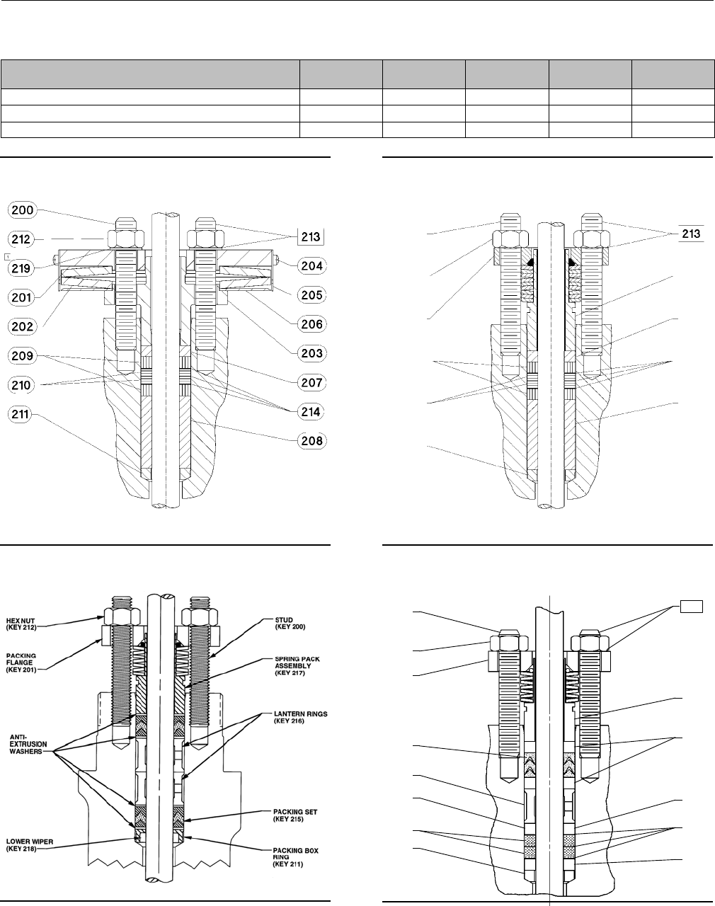
Figure 11. Typical ENVIRO-SEAL Packing System
with PTFE Packing
A6297-1
Figure 12. Typical ENVIRO-SEAL Packing System
with Graphite ULF Packing
PACKING
RING
(KEY 209)
PACKING
RING
(KEY 210)
PACKING
BOX RING
(KEY 211)
STUD
(KEY 200)
SPRING
PACK
ASSEMBLY
(KEY 217)
HEX NUT
(KEY 212)
PACKING
FLANGE
(KEY 201)
GUIDE
BUSHING
(KEY 207)
PACKING
WASHERS
(KEY 214)
GUIDE
BUSHING
(KEY 208)
39B4612/A
Figure 13. Typical ENVIRO-SEAL Packing System
with Duplex Packing
200
212
201
215
216
207
209
211
217
207
207
207
214
213
A6722

Instruction Manual
D100398X012
ET Valve
October 2014
24
Parts List
Note
Part numbers are shown for recommended spares only. For part
numbers not shown, contact your Emerson Process Management sales
office.
Bonnet (figures 3 through 9 and
figure 14)
Key Description Part Number
1 Bonnet/ENVIRO-SEAL bellows seal bonnet
If you need a bonnet or an ENVIRO-SEAL bellows seal bonnet as a
replacement part, order by valve size and stem diameter, serial
number, and desired material.
2 Extension Bonnet Baffle
3 Packing Flange
3 ENVIRO-SEAL bellows seal packing flange
4 Packing Flange Stud
4 ENVIRO-SEAL bellows seal stud bolt
5 Packing Flange Nut
5 ENVIRO-SEAL bellows seal hex nut
6* Packing set, PTFE see following table
6* ENVIRO-SEAL bellows seal packing set
PTFE for 9.5 mm (3/8 inch) stem (1 req'd
for single packing, 2 req'd for double
packing) 12A9016X012
PTFE for NPS 2 with 12.7 mm (1/2 inch)
stem (2 req'd for double packing) 12A9016X012
PTFEforNPS3and4with12.7mm
(1/2 inch) stem (2 req'd for double
packing) 12A8832X012
7* Packing ring, PTFE composition see following table
7* ENVIRO-SEAL bellows seal packing ring
for low chloride graphite ribbon/filament
packing arrangement
Ribbon packing ring for 9.5 mm (3/8 inch)
and NPS 2 with 12.7 mm (1/2 inch) stem
(4 req'd) 18A0908X012
Filament packing ring for 9.5 mm
(3/8 inch) and NPS 2 with 12.7 mm
(1/2 inch) stem (4 req'd) 1P3905X0172
Ribbon packing ring for NPS 3 and 4
with 12.7 mm (1/2 inch) stem (4 req'd) 18A0918X012
FilamentpackingringforNPS3and4
with 12.7 mm (1/2 inch) stem (4 req'd) 14A0915X042
8Spring
8 Lantern ring
8 ENVIRO-SEAL bellows seal spring
8 ENVIRO-SEAL bellows seal spacer
10 Special washer
11* Packing Box Ring, S31600
9.5 mm (3/8 inch) stem, 1J873135072
12.7 mm (1/2 inch) stem, 1J873235072
19.1 mm (3/4 inch) stem, 1J873335072
25.4 mm (1-inch) stem, 1J873435072
31.8 mm (1-1/4 inch) stem, 1J873535072
Key Description Part Number
12* Upper Wiper, felt
9.5 mm (3/8 inch) stem 1J872606332
12.7 mm (1/2 inch) stem 1J872706332
19.1 mm (3/4 inch) stem 1J872806332
25.4 mm (1-inch) stem 1J872906332
31.8 mm (1-1/4 inch) stem 1J873006332
12* ENVIRO-SEAL bellows seal upper wiper
For 9.5 mm (3/8 inch) and NPS 2 with 12.7 mm
(1/2 inch) stem 18A0868X012
For NPS 3 and 4 with 12.7 mm (1/2 inch) stem 18A0870X012
13 Packing Follower
13* ENVIRO-SEAL bellows seal bushing
For 9.5 mm (3/8 inch) stem (1 req'd),
for NPS 2 with 12.7 mm (1/2 inch) stem
(2 req'd)
S31600/PTFE 18A0820X012
R30006 18A0819X012
S31600/Cr Coated 11B1155X012
ForNPS3and4with12.7mm(1/2inch)
stem (1 req'd)
S31600/PTFE 18A0824X012
R30006 18A0823X012
S31600/Cr Coated 11B1157X012
13* ENVIRO-SEAL bellows seal bushing/liner
For 9.5 mm (3/8 inch) stem (1 req'd),
for NPS 2 with 12.7 mm (1/2 inch) stem
(2 req'd)
N10276 bushing, PTFE/glass liner 12B2713X012
N10276 bushing, PTFE/carbon liner 12B2713X042
ForNPS3and4with12.7mm(1/2inch)
stem (1 req'd)
N10276 bushing, PTFE/glass liner 12B2715X012
N10276 bushing, PTFE/carbon liner 12B2715X042
14 Pipe Plug
14 Lubricator
14 Lubricator/Isolating Valve
15 Yoke Locknut
15 ENVIRO-SEAL bellows seal Locknut
16 Pipe Plug
16 ENVIRO-SEAL bellows seal pipe plug
20* ENVIRO-SEAL bellows seal stem/bellows assembly
1 Ply Bellows
S31600 trim mat'l, N06625 bellows mat'l
NPS 1 w/ 9.5 mm (3/8 inch) stem 32B4224X012
NPS 1-1/2 w/ 9.5 mm (3/8 inch) stem 32B4225X012
NPS 2 w/ 12.7 mm (1/2 inch) stem 32B4226X012
NPS 3 w/ 12.7 mm (1/2 inch) stem 32B4227X012
NPS 4 w/ 12.7 mm (1/2 inch) stem 32B4228X012
N06022 trim mat'l, N06022 bellows mat'l
NPS 1 w/ 9.5 mm (3/8 inch) stem 32B4224X022
NPS 1-1/2 w/ 9.5 mm (3/8 inch) stem 32B4225X022
NPS 2 w/ 12.7 mm (1/2 inch) stem 32B4226X022
NPS 3 w/ 12.7 mm (1/2 inch) stem 32B4227X022
NPS 4 w/ 12.7 mm (1/2 inch) stem 32B4228X022
2 Ply Bellows
S31600 trim mat'l, N06625 bellows mat'l
NPS 1 w/ 9.5 mm (3/8 inch) stem 32B4224X032
NPS 1-1/2 w/ 9.5 mm (3/8 inch) stem 32B4225X032
NPS 2 w/ 12.7 mm (1/2 inch) stem 32B4226X032
NPS 3 w/ 12.7 mm (1/2 inch) stem 32B4227X032
*Recommended spare parts

Instruction Manual
D100398X012
ET Valve
October 2014
25
Keys 6*, 7*, 8, and 10 Packing Box Parts(1)
DESCRIPTION KEY
NO.
STEM DIAMETER, mm (INCHES)
9.5 (3/8) 12.7 (1/2) 19.1 (3/4) 25.4 (1) 31.8 (1-1/4)
PTFE
V-Ring Packing
Packing Set, PTFE (1 req'd for single,
2 req'd for double)(2) 61R290001012 1R290201012 1R290401012 1R290601012 1R290801012
Spring, Stainless Steel (for single only) 81F125437012 1F125537012 1F125637012 1D582937012 1D387437012
Lantern Ring, Stainless Steel
(for double only) 81F364135072 1J962335072 0N028435072 0U099735072 0W087135072
Quantity required Double ——— 12111
Special Washer, Stainless Steel
(for single only) 10 1F125236042 1F125136042 1F125036042 1H982236042 1H995936042
PTFE/
Composition
Packing
Packing Ring, PTFE composition 71F3370X0012 1E319001042 1E319101012 1D7518X0012 1D7520X0012
Quantity required Double ——— 710 888
Lantern Ring, Stainless Steel
(1 required) 81F364135072 1J962335072 0N028435072 0U099735072 0W087135072
Graphite
Ribbon/
Filament
Graphite Ribbon Ring 71V3160X0022 1V3802X0022 1V2396X0022 1U6768X0022 1V5666X0022
Quantity required Single ——— 22222
Double ——— 33333
Graphite Filament Ring 71F3370X0322 1E3190X0222 1E3191X0282 1D7518X0132 1D7520X0162
Quantity required Single ——— 22333
Double ——— 44555
Lantern Ring 81F364135072 1J962335072 0N028435072 0U099735072 0W087135072
Quantity required Single ——— 23222
Double ——— 12111
Warning Tag 11B9513X012 11B9513X012 11B9513X012 11B9513X012 11B9513X012
1. For ENVIRO-SEAL or HIGH-SEAL packing box parts, see instruction manual ENVIRO-SEAL Packing System for Sliding-Stem Valves, D101642X012 or HIGH-SEAL Live-Loaded Packing System,
D101453X012.
2. Key 6 for double construction contains one extra packing ring for the 9.5 mm (3/8 inch) stem and one extra lower wiper for all sizes. Discard upon assembly.
Key Description Part Number
NPS 4 w/ 12.7 mm (1/2 inch) stem 32B4228X032
N06022 trim mat'l, N06022 bellows mat'l
NPS 1 w/ 9.5 mm (3/8 inch) stem 32B4224X042
NPS 1-1/2 w/ 9.5 mm (3/8 inch) stem 32B4225X042
NPS 2 w/ 12.7 mm (1/2 inch) stem 32B4226X042
NPS 3 w/ 12.7 mm (1/2 inch) stem 32B4227X042
NPS 4 w/ 12.7 mm (1/2 inch) stem 32B4228X042
22* ENVIRO-SEAL bellows seal bonnet gasket
(graphite/S31600)
NPS 1/2 through 1-1/4 12B6316X022
NPS 1-1/2 12B6317X022
NPS 2 12B6318X022
Key Description Part Number
NPS 3 12B6319X022
NPS 4 12B6320X022
24 ENVIRO-SEAL bellows seal adaptor
25 Cap Screw
26 Hex Nut
27 Pipe Nipple for lubricator/isolating valve
28 ENVIRO-SEAL bellows seal nameplate, warning
29 ENVIRO-SEAL bellows seal drive screw
34 Lubricant, Anti-Seize (not included with valve)
36* ENVIRO-SEAL bellows seal pin 12B3951X012
37 ENVIRO-SEAL bellows seal warning tag
38 ENVIRO-SEAL bellows seal tie
39 ENVIRO-SEAL bellows seal thrust ring
*Recommended spare parts
Instruction Manual
D100398X012
ET Valve
October 2014
26
Figure 14. Typical Bonnets
APPLY LUB
E0201
30A9425-A
CU3911-C
42B3947-A
ENVIRO-SEAL
BELLOWS SEAL BONNET
STYLE 1 OR 2
EXTENSION BONNET
DETAIL OF 127 mm (5-INCH) YOKE
BOSS ACTUATOR BOLTING
PLAIN BONNET
Instruction Manual
D100398X012
ET Valve
October 2014
27
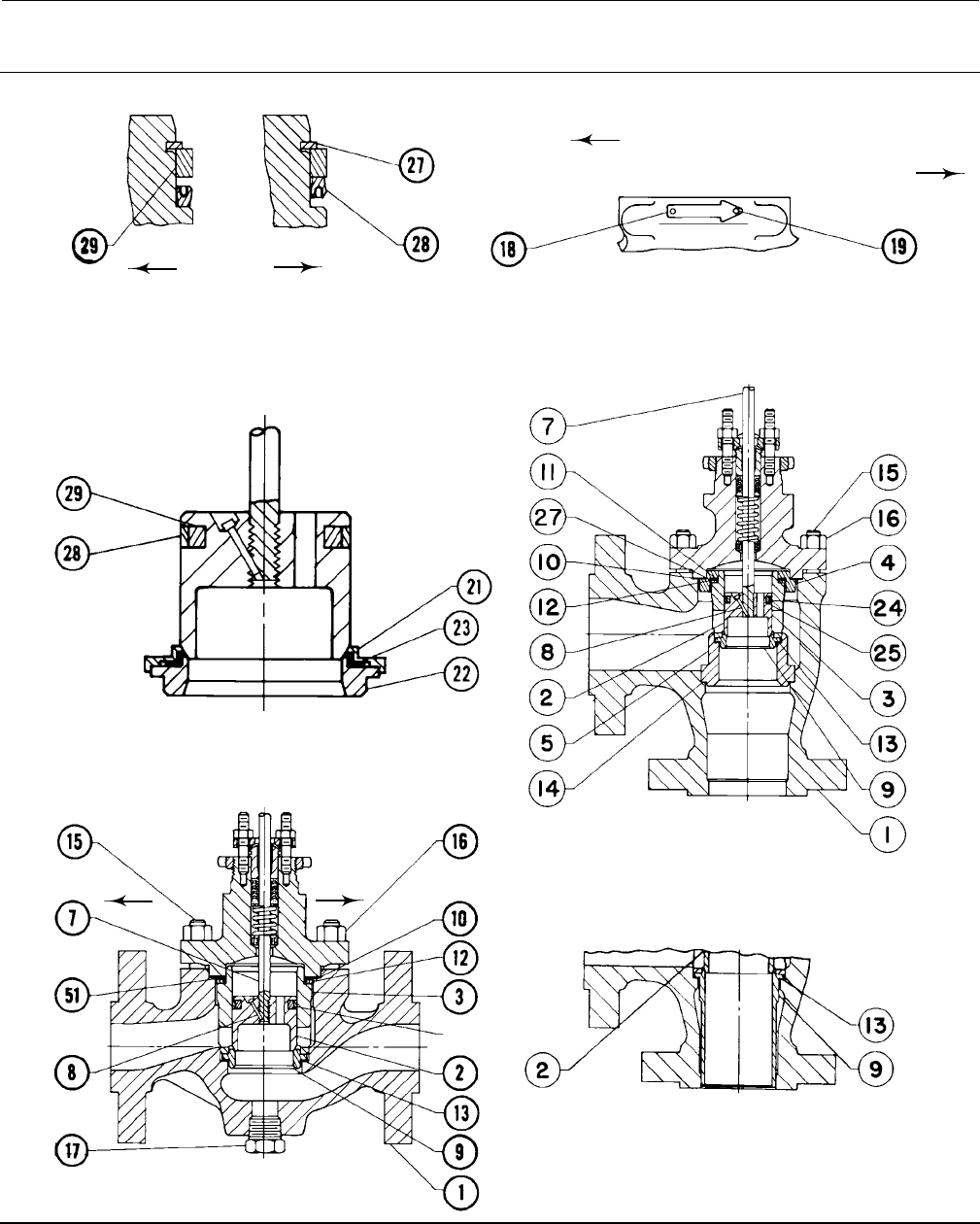
Figure 15. Alternate Configurations
FLOW UP
NPS 1 TO 8 ET USING PEEK ANTI-EXTRUSION RINGS
FLOW DOWN
21B2120-A
A6137
2
27
29
28
2
27
29
28
Key Description Part Number
Valve Body
(figures 16 through 21)
1ValveBody
If you need a valve body as a replacement part, order by valve
size, serial number, and desired material.
2* Valve plug see following table
3* Cage see following table
4 Trim adaptor
5 Trim adaptor
7* Valve plug stem see following table
8* Pin, 316 Stainless Steel
9.5 mm (3/8 inch) stem 1V322635072
12.7 mm (1/2 inch) stem 1V322735072
19.1 mm (3/4 inch) stem 1V326035072
25.4 mm (1 inch) or 31.8 mm (1-1/4 inch)
stem 1V334035072
9* Liner see following table
9* Seat Ring see following table
10* Bonnet Gasket see following table
11* Cage Gasket see following table
12* Spiral-Wound Gasket see following table
13* Seat Ring or Liner Gasket see following table
14* Adaptor Gasket see following table
15 Cap Screw
15 Stud
16 Nut
17 Pipe Plug, for use in valves with drain tapping only
18 Flow Direction Arrow
19 Drive Screw, Stainless Steel
20* Adaptor Gasket see following table
21* Seat Disk Retainer see following table
22* Disk Seat see following table
Key Description Part Number
23* Disk see following table
24* Seal Ring (EAT) see following table
25* Backup Ring (EAT) see following table
26 Load Ring (for NPS 8 ET only)
27* Retaining Ring see following table
27* Shim (EAT) see following table
28* Seal Ring (ET) see following table
29* Backup Ring (ET) see following table
31* Whisper Trim III Cage Retainer for
LevelsA3,B3&C3(NPS6ETonly)
410 Stainless steel 22A3255X012
WCC steel (ENC) 22A3256X012
316 Stainless Steel (ENC) 22A3256X022
316 Stainless Steel w/CoCr-A bore 22A3257X012
316 Stainless Steel (Cr Cr) 31A9792X012
31* Whisper Trim III Cage Retainer & Baffle
Ass'y for Level D3 (NPS 6 ET only)
410 Stainless Steel retainer & steel
baffle 22A3258X012
WCC steel (ENC) retainer & steel baffle 22A3258X022
316 Stainless Steel (ENC) retainer
& steel baffle 22A3258X052
316 Stainless Steel w/CoCr-A
retainer & steel baffle 22A3258X032
316 Stainless steel (ENC) retainer & 316
stainless steel baffle 22A3258X042
316 Stainless Steel (Cr Cr)
retainer & 316 Stainless Steel baffle 22A3258X062
32 Cavitrol III Bonnet Spacer
32 Whisper Trim III Bonnet Spacer (NPS 6 ET only)
51* Shim see following table
54 Wire
63* Anti-Extrusion Ring see following table
*Recommended spare parts
Instruction Manual
D100398X012
ET Valve
October 2014
28
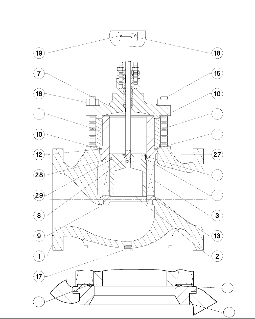
Figure16.NPS1Through6FisherETandEATValves
CORRECT ORIENTATION OF PLUG
WITH SPRING-LOADED SEAL RING
VIEW A
FLOW UP
VIEW A
FLOW DOWN
FLOW DIRECTION
WhisperTrimCAGE
LINEAR, QUICK OPENING, EQUAL PERCENTAGE OR Cavitrol CAGES
DETAIL OF PTFE SEAT AND
TWO-PIECE SEAL RING
FULL-CAPACITY METAL-SEAT ET
WITH OPTIONAL DRAIN PLUG
DETAIL OF LINER-STYLE EAT (METAL SEAT ONLY)
SEAT-RING-STYLE METAL EAT
44A7928-C
E0198
FLOW
UP
FLOW
DOWN
Instruction Manual
D100398X012
ET Valve
October 2014
29
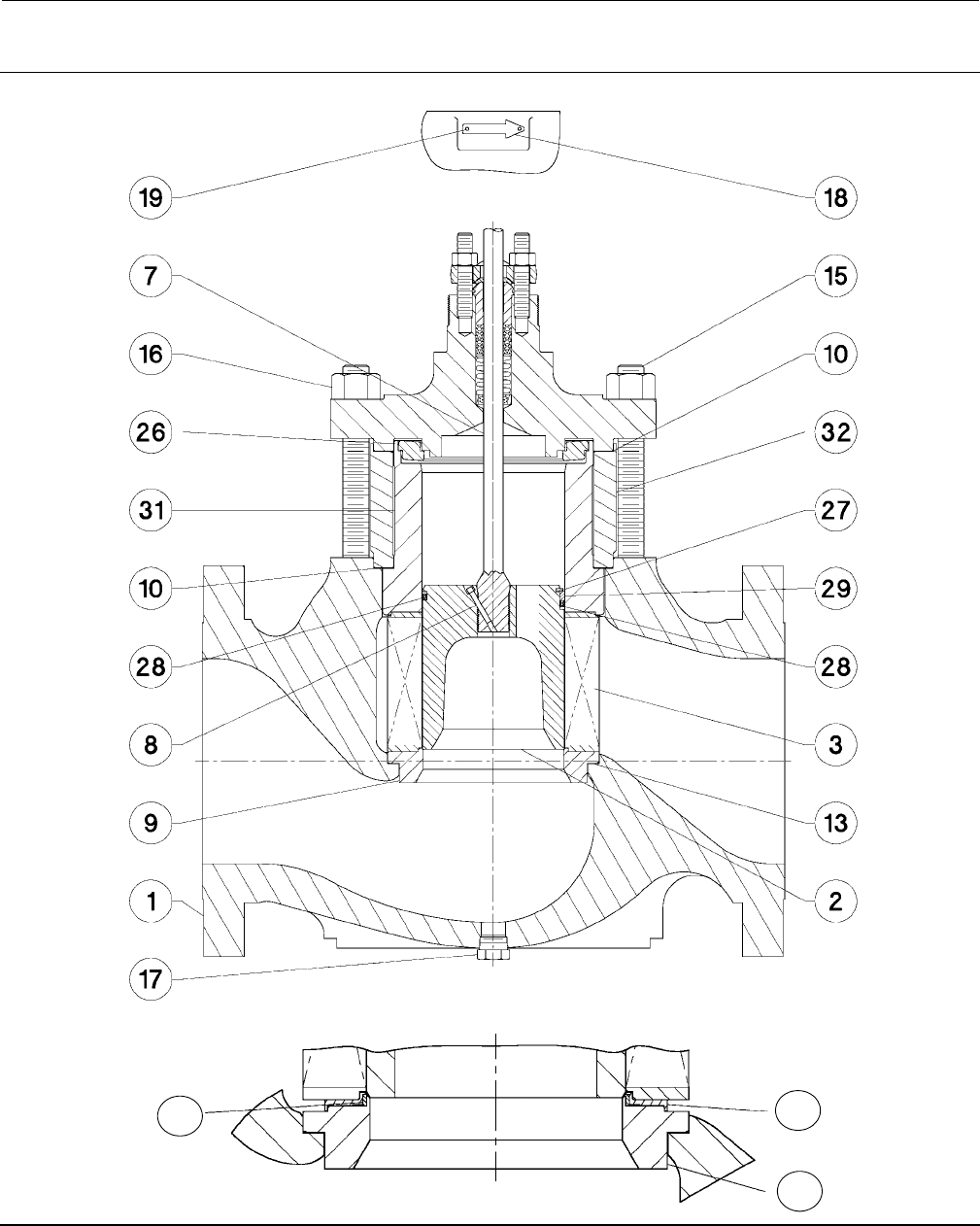
Figure 17. Fisher ET Valve Assembly with Whisper Trim III Cage and Optional Drain Plug
FULL-CAPACITY METAL-SEAT CONSTRUCTION
DETAIL OF PTFE SEAT
E0197
Instruction Manual
D100398X012
ET Valve
October 2014
30
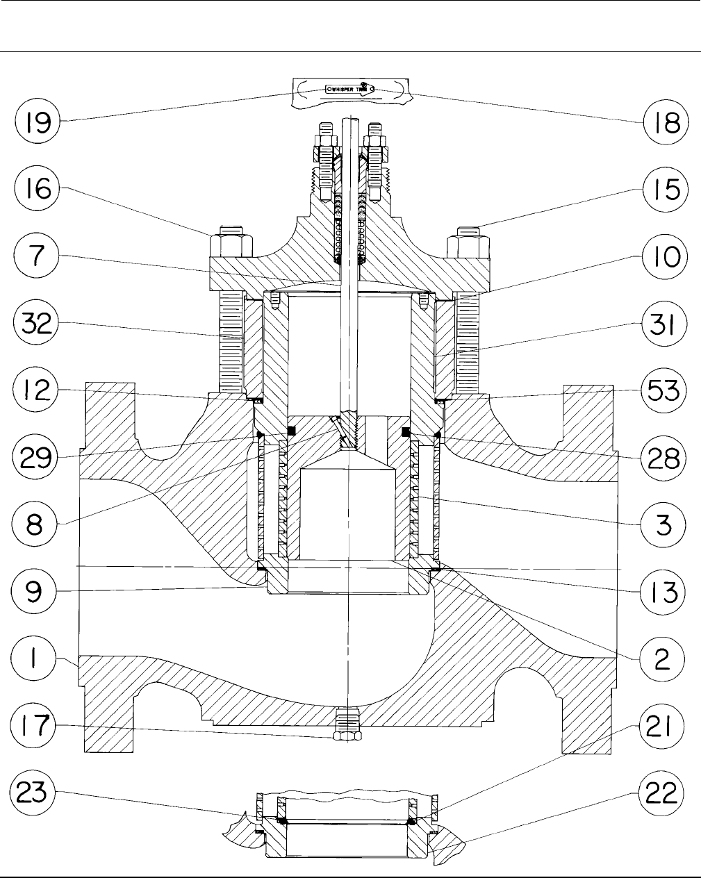
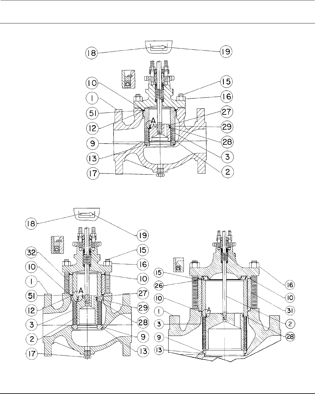
Figure 18. Fisher ET Valve Assembly with WhisperFlo Cage and Optional Drain Plug
31 32
51
29
28
23
21
E0199
DETAIL OF PTFE SEAT 22
Instruction Manual
D100398X012
ET Valve
October 2014
31
Figure 19. NPS 8 Fisher ET Valve Assembly with WhisperFlo Cage and Optional Drain Plug
E0200
DETAIL OF PTFE SEAT
21
22
23
Instruction Manual
D100398X012
ET Valve
October 2014
32
Figure 20. Details of Cavitrol III and NPS 8 Fisher ET Valves with Optional Drain Plug
FLOW DIRECTION
VIEW A
54A8144-B
1-STAGE Cavitrol III CONSTRUCTIONS THRU NPS 6 SHOWING CORRECT
ORIENTATION OF PLUG WITH SPRING-LOADED SEAL RING
PLUG AND SEAL RING WITH SPRING LOADING SHOWN IN CORRECT
ORIENTATION FOR 2-STAGE Cavitrol III CAGE
54A7268-B
54A8132-A
VIEW A
VIEW A
NPS 1 THROUGH 6 VALVE SIZE NPS 8 VALVE SIZE
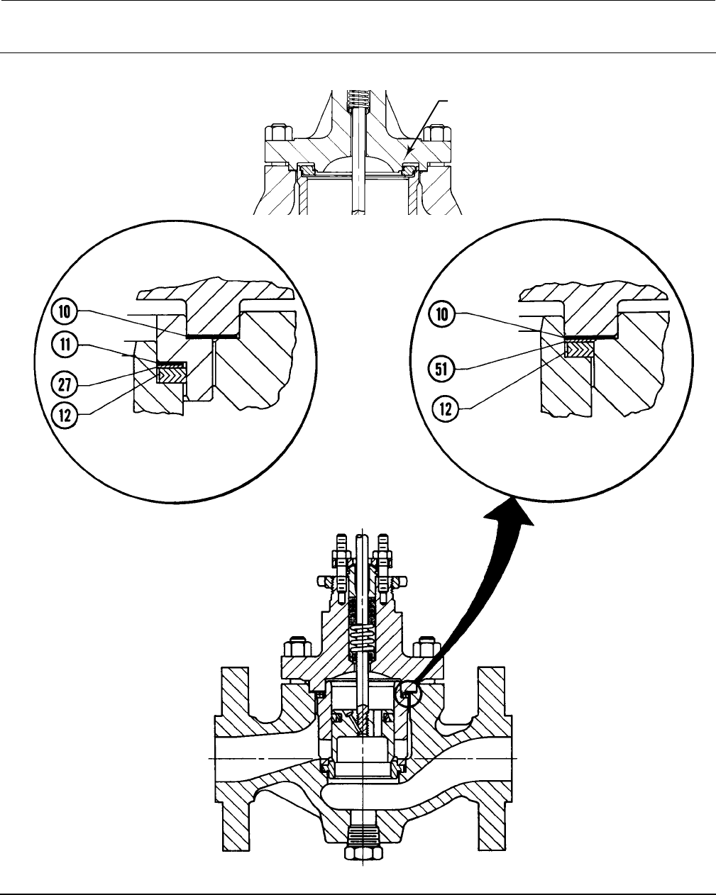
Instruction Manual
D100398X012
ET Valve
October 2014
33
Figure 21. Gasket Set Detail shown with Optional Drain Plug
RESTRICTED-TRIM DETAIL
16A1943-A
30A9542-F
FULL-CAPACITY-TRIM DETAIL
LOAD RING
STANDARD NPS 8
CONSTRUCTION
40A3290

Instruction Manual
D100398X012
ET Valve
October 2014
34
Actuator Groups
Group 1
54 mm (2-1/8 inches),
71 mm (2-13/16 inches),
or 90 mm (3-9/16 inches) Yoke
Boss
Group 100
127 mm (5 inches) Yoke Boss
3 inches maximum travel
Group 401
90.5 mm (3-9/16 inches) Yoke Boss
3.25 to 4 inches maximum travel
Group 404
127 mm (5 inches) Yoke Boss
4 inches maximum travel
585C
657
1008
657
657 MO
657-4
657-4 MO
667
667 MO
667-4
667-4 MO
667
667-4
585C
1B
618
644 & 645
657 & 667–76.2 mm (3 inches)
maximum travel
1008–71.4 mm (2-13/16 inches)
Yoke Boss
Group 405
127 mm (5 inches) Yoke Boss
4 inches maximum travel
657 MO
657-4 MO
Group 402
90.5 mm (3-9/16 inches) Yoke Boss
4inchesmaximumtravel
Group 406
127 mm (5 inches) Yoke Boss
4 inches maximum travel
Group 101
127 mm (5 inches) Yoke Boss
3 inches maximum travel
457-7
585C
667 MO
667-4 MO
667
Group 403
90.5 mm (3-9/16 inches) Yoke Boss
4inchesmaximumtravel
Group 407
127 mm (5 inches) Yoke Boss
4 inches maximum travel
Group 400
71.4 mm (2-13/16 inches)
Yoke Boss
4 inches maximum travel
585C
1008
585C
657
585C
Group 801
90.5 mm (3-9/16 inches) Yoke Boss
8inchesmaximumtravel
Group 802
127 mm (5 inches) Yoke Boss
8 inches maximum travel
585C 585C
Key 2* Valve Plug for Constructions with Two-Piece Seal Ring
VALVE SIZE, NPS STEM DIAMETER 416 STAINLESS
STEEL HARDENED
(STD)
316
STAINLESS
STEEL(1)
316 STAINLESS
STEEL w/CoCr-A
ON SEAT(1)
316 STAINLESS STEEL
w/CoCr-A ON SEAT &
GUIDE(1)
ET EAT mm Inches
1, 1-1/4, or
1-1/2 x 1 1or2x1 9.5
12.7
3/8
1/2
1V657146172
1V657246172
1V657135072
1V657235072
11A5315X012
11A5316X012
11A5317X012
11A5318X012
1-1/2 29.5
12.7
3/8
1/2
1V657346172
1V657446172
1V657335072
1V657435072
11A5321X012
10A4439X012
10A4438X012
10A4611X012
2or3x2 4x2 12.7
19.1
1/2
3/4
1V657546172
1V657646172
1V657535072
1V657635072
11A5324X012
11A5325X012
11A5326X012
11A5327X012
2x1 --- 12.7 1/2 1V657246172 1V657235072 11A5316X012 11A5318X012
2-1/2 or
4 x 2-1/2 3or6x2-1/2 12.7
19.1
1/2
3/4
1V657746172
1V657846172
1V657735072
1V657835072
11A5330X012
11A5331X012
11A5332X012
11A5333X012
2-1/2 x 1-1/2 3x1-1/2 12.7 1/2 1V657446172 1V657435072 10A4439X012 10A4611X012
3 4 12.7
19.1
1/2
3/4
1V657946172
1V658046172
1V657935072
1V658035072
11A5336X012
11A5014X012
11A5337X012
11A5338X012
4 6
12.7
19.1
25.4
1/2
3/4
1
1V658146172
1V6582X0022
1V658346172
1V658135072
1V6582X0072
1V658335072
11A5341X012
11A5342X012
11A5343X012
11A5344X012
11A5345X042
11A5346X012
6---
19.1
25.4
31.8
3/4
1
1-1/4
1V658446172
1V658546172
1V658646172
1V658435072
1V658535072
1V658635072
11A5350X012
10A5107X012
10A5108X012
11A5351X012
20A0103X012
20A4608X012
1. Not for use with 17-4PH stainless steel cages above 210_C(410_F).
*Recommended spare parts

Instruction Manual
D100398X012
ET Valve
October 2014
35
Keys 2*, 7*, and 8* Valve Plug and Stem Assembly for Plain Bonnet with Two-Piece Seal Ring
VALVE SIZE, NPS STEM DIAMETER 416 STAINLESS
STEEL HARDENED
(STD)
316
STAINLESS
STEEL(1)
316 STAINLESS
STEEL w/CoCr-A
ON SEAT(1)
316 STAINLESS
STEEL w/CoCr-A
ON SEAT &
GUIDE(1)
ET EAT mm Inches
1or1-1/4 19.5
12.7
3/8
1/2
1V6571X0032
1V6572X0022
1V6571X0052
1V6572X0062
11A5315X032
11A5316X022
11A5317X042
11A5318X042
1-1/2 29.5
12.7
3/8
1/2
1V6573X0042
1V6574X0012
1V6573X0052
1V6574X0032
11A5321X022
---
10A4438X022
10A4611X042
1-1/2 x 1 2x1 9.5
12.7
3/8
1/2
1V6571X0042
1V6572X0042
1V6571X0092
---
---
---
11A5317X072
11A5318X032
2or3x2 4x2 12.7
19.1
1/2
3/4
1V6575X0052
1V6576X0012
1V6575X0062
---
11A5324X022
---
11A5326X022
11A5327X032
2x1 --- 12.7 1/2 1V6572X0022 1V6572X0062 11A5316X022 11A5318X042
2-1/2 or
4 x 2-1/2 3or6x2-1/2 12.7
19.1
1/2
3/4
1V6577X0042
1V6578X0012
1V6577X0062
1V6578X0022
11A5330X022
11A5331X022
11A5332X022
---
2-1/2 x 1-1/2 3x1-1/2 12.7 1/2 1V6574X0012 1V6574X0032 --- 10A4611X112
3 4 12.7 1/2 1V6579X0092 1V6579X0112 11A5336X032 11A5337X082
4 6 12.7
19.1
1/2
3/4
1V6581X0042
1V6582X0022
1V6581X0052
1V6582X0072
11A5341X032
---
11A5344X022
11A5345X042
6--- 19.1 3/4 1V6584X0042 1V6584X0062 11A5350X032 21A5351X062
1. Not for use with 17-4PH stainless steel cages above 210_C(410_F).
Keys 2*, 7*, and 8* Valve Plug and Stem Assembly for Style 1 Extension Bonnet with Two-Piece Seal Ring
VALVE SIZE, NPS STEM DIAMETER 416 STAINLESS
STEEL HARDENED
(STD)
316
STAINLESS
STEEL(1)
316 STAINLESS
STEEL w/CoCr-A
ON SEAT(1)
316 STAINLESS STEEL
w/CoCr-A ON SEAT &
GUIDE(1)
ET EAT mm Inches
1or1-1/4 19.5
12.7
3/8
1/2
1V6571X0072
1V6572X0032
1V6571X0062
---
---
11A5316X032
11A5317X082
---
1-1/2 29.5
12.7
3/8
1/2
1V6573X0072
1V6574X0052
---
---
11A5321X042
---
10A4438X032
10A4611X112
1-1/2 x 1 2x1 9.5
12.7
3/8
1/2
1V6571X0102
1V6572X0152
---
---
---
---
11A5317X052
---
2or3x2 4x2 12.7 1/2 1V6575X0182 1V6575X0122 11A5324X042 11A5326X062
2x1 --- 12.7 1/2 1V6572X0032 --- 11A5316X032 ---
2-1/2 or
4 x 2-1/2 3or6x2-1/2 12.7 1/2 1V6577X0052 --- --- 11A5332X202
2-1/2 x 1-1/2 3x1-1/2 12.7 1/2 1V6574X0052 --- --- 10A4611X112
3 4 12.7 1/2 1V6579X0082 1V6579X0072 --- 11A5337X062
4 6 12.7 1/2 1V6581X0072 1V6581X0062 --- 11A5344X052
6--- 19.1 3/4 1V6584X0052 1V6584X0112 --- 21A5351X052
1. Not for use with 17-4PH stainless steel cages above 210_C(410_F).
*Recommended spare parts

Instruction Manual
D100398X012
ET Valve
October 2014
36
Key 2* Valve Plug for Spring-Loaded Seal Ring Constructions
VALVE SIZE, NPS STEM DIAMETER 416 STAINLESS STEEL
HARDENED
316 STAINLESS
STEEL(1)
316 STAINLESS STEEL
w/CoCr-A SEAT & GUIDE(1)
ET EAT mm Inches
1, 1-1/4, or 1-1/2 x 1 19.5 3/8 20A4103X012 20A4103X022 20A4104X012
1-1/2 or
2-1/2 x 1-1/2 2or3x1-1/2 9.5
12.7
3/8
1/2
20A6711X012
20A4150X012
20A6711X022
20A4150X022
22A5941X012
20A4151X012
2or3x2 4x2 12.7
19.1
1/2
3/4
20A4097X012
20A4098X012
20A4097X022
20A4098X022
20A4099X012
20A4100X012
2-1/2 or
4 x 2-1/2 3or6x2-1/2 12.7
19.1
1/2
3/4
20A9533X012
20A4144X012
20A9533X022
20A4144X022
20A9534X012
20A4146X012
3 4 12.7
19.1
1/2
3/4
20A5414X012
20A5342X012
20A5414X022
20A5342X022
22A3458X012
20A5344X012
4 6
12.7
19.1
25.4
1/2
3/4
1
20A2641X012
20A4194X012
20A4195X012
20A2641X022
20A4194X0A2
20A4195X032
21A0187X012
20A4197X012
20A4198X012
6--- 19.1
25.4
3/4
1
20A2642X012
20A5621X012
20A2642X022
20A5621X022
21A8443X012
20A6706X012
8---
19.1
25.4
31.8
3/4
1
1-1/4
21A5356X012
21A5357X012
21A5358X012
21A5356X022
21A5357X022
21A5358X022
21A5362X012
21A5363X012
21A5364X012
1. Not for use with 17-4PH stainless steel cages above 210_C(410_F).
Keys 2*, 7*, and 8* Valve Plug and Stem Assembly for Plain Bonnet for Spring-Loaded Seal Ring Constructions
VALVE SIZE, NPS STEM DIAMETER 416 STAINLESS STEEL
HARDENED
316 STAINLESS
STEEL(1)
316 STAINLESS STEEL
w/CoCr-A SEAT &
GUIDE(1)
ET EAT mm Inches
1, 1-1/4 19.5 3/8 20A4103X052 --- ---
1-1/2 29.5
12.7
3/8
1/2
20A6711X032
20A4150X062
20A6711X042
---
22A5941X022
---
1-1/2 x 1 2x1 9.5 3/8 20A4103X042 --- ---
2or3x2 4x2 12.7 1/2 20A4097X062 20A4097X182 20A4099X102
2-1/2 or 4 x 2-1/2 3or6x2-1/2 12.7 1/2 20A9533X052 20A9533X062 20A9534X092
2-1/2 x 1-1/2 3 x 1-1/2 12.7 1/2 20A4150X062 --- ---
3 4 12.7
19.1
1/2
3/4
20A5414X062
20A5342X082
20A5414X052
---
22A3458X022
20A5344X042
4 6 12.7
19.1
1/2
3/4
20A2641X042
20A4194X052
20A2641X162
---
---
---
6--- 19.1 3/4 20A2642X052 20A2642X062 21A8443X032
8--- 19.1 3/4 21A5356X052 21A5356X132 21A5362X062
1. Not for use with 17-4PH stainless steel cages above 210_C(410_F).
Key 2* 1-Stage Cavitrol III Valve Plug (Fisher ET only)
VALVE SIZE, NPS STEM DIAMETER 420 STAINLESS STEEL 316 STAINLESS STEEL w/CoCr-A ON
SEAT & GUIDE(1)
mm Inches
112.7 1/2 28A1001X012 28A2226X012
1-1/2 12.7 1/2 28A1002X012 28A2227X012
212.7
19.1
1/2
3/4
28A1003X012
28A1004X012
28A2228X012
28A2229X012
2-1/2 12.7
19.1
1/2
3/4
28A1005X012
28A1006X012
28A2230X012
28A2231X012
312.7
19.1
1/2
3/4
28A1007X012
28A1008X012
28A2232X012
28A2233X012
419.1
25.4
3/4
1
28A1010X012
28A1011X012
28A2234X012
28A2235X012
625.4
31.8
1
1-1/4
28A1013X012
28A1014X012
28A2236X012
28A2237X012
825.4
31.8
1
1-1/4
28A1016X012
28A1017X012
28A2238X012
28A2239X012
1. Not for use with 17-4PH stainless steel cages above 210_C(410_F).
*Recommended spare parts

Instruction Manual
D100398X012
ET Valve
October 2014
37
Key 2* 2-Stage Cavitrol III Valve Plug & Stem Ass'y (Fisher ET only)
VALVE
SIZE, NPS
TRAVEL
ACTUATOR
GROUP (FROM
PRECEDING
TABLE)
STEM DIAMETER 316 STAINLESS STEEL
STEM 17-4PH STAINLESS STEEL STEM
mm Inches mm Inches 420 HT Valve
Plug
316 Stainless
Steel Valve
Plug
w/CoCr-A
Seat & Guide
420 HT Valve
Plug
316 Stainless
Steel Valve
Plug
w/CoCr-A
Seat & Guide
125 1 1 12.7 1/2 24A5265X022 24A5519X022 ——— ———
1-1/2 38 1.5 112.7 1/2 24A5266X022 24A5286X022 ——— ———
251 2 1 12.7
19.1
1/2
3/4
24A3038X022
24A5550X022
24A5287X022
24A5551X022
24A3038X032
———
24A5287X032
———
2-1/2 64 2.5
1
400
1, 402, 403
12.7
12.7
19.1
1/2
1/2
3/4
24A5267X022
24A5267X032
24A5268X022
24A5288X022
24A5288X032
24A5289X022
24A5267X042
24A5267X052
———
24A5288X042
24A5288X052
———
376 31, 400
1, 402, 403
12.7
19.1
1/2
3/4
24A5269X022
23A9452X012
24A5290X022
24A5291X022
24A5269X032
———
24A5290X032
———
4
76
102
76
3
4
3
1, 402, 403
401, 402, 403
100, 101
19.1
19.1
25.4
3/4
3/4
1
23A5818X022
23A5818X032
24A5270X022
24A5292X022
24A5292X032
24A5293X022
———
———
———
———
———
———
102
102
102
4
4
4
404
405, 406
407
25.4
25.4
25.4
1
1
1
24A5270X022
24A5270X042
24A5270X032
24A5293X022
24A5293X042
24A5293X032
———
———
———
———
———
———
6
76
102
102
3
4
4
1
401, 403
402
19.1
19.1
19.1
3/4
3/4
3/4
23A5803X022
23A5803X022
23A5803X042
24A5294X022
24A5294X022
24A5294X042
23A5803X032
23A5803X032
23A5803X052
24A5294X032
24A5294X032
24A5294X052
76
102
102
3
4
4
100, 101
405, 406
407
25.4
25.4
25.4
1
1
1
24A3028X042
24A3028X052
24A3028X062
24A5295X022
24A5295X032
24A5295X042
———
———
———
———
———
———
8
76
102
102
153
76
3
4
4
6
3
1
401, 403
402
801
100, 101
19.1
19.1
19.1
19.1
25.4
3/4
3/4
3/4
3/4
1
24A1141X092
24A1141X092
24A1141X042
24A1141X032
24A5273X022
34A4269X042
34A4269X042
34A4269X062
34A4269X022
34A4270X022
24A1141X072
24A1141X072
24A1141X082
24A1141X062
24A5273X032
34A4269X052
34A4269X052
34A4269X072
34A4269X032
34A5270X032
102
153
4
6
404
802
25.4
25.4
1
1
24A5273X022
24A5273X022
34A4270X022
34A4270X022
24A5273X032
24A5273X032
34A4270X032
34A4270X032
102
102
76
4
4
3
407
405, 406
100, 101
25.4
25.4
31.8
1
1
1-1/4
24A5273X042
24A5273X062
24A7259X022
34A4270X042
34A4270X062
34A7260X022
24A5273X052
24A5273X072
———
34A4270X052
34A4270X072
———
102
153
102
102
4
6
4
4
404
802
407
405, 406
31.8
31.8
31.8
31.8
1-1/4
1-1/4
1-1/4
1-1/4
24A7259X022
24A7259X022
24A7259X032
24A7259X042
34A7260X022
34A7260X022
34A7260X032
34A7260X042
———
———
———
———
———
———
———
———
Key 2* Whisper Trim III Valve Plug with Two-Piece Seal Ring (NPS 6 Fisher ET only)
STEM DIAMETER 17-4PH STAINLESS
STEEL (H900) 316 STAINLESS STEEL 316 STAINLESS STEEL
W/CoCr-A ON SEAT
316 STAINLESS STEEL
W/CoCr-A ON SEAT
AND GUIDE
316 STAINLESS STEEL
W/CoCr-A ON SEAT
AND GUIDE(1)
mm Inches
19.1
25.4
3/4
1
22A3259X012
22A3262X012
22A3259X022
22A3262X022
22A3260X012
22A3263X012
22A3261X012
22A3264X012
22A3267X012
22A3268X012
1. High temperature.
Key 2* Whisper Trim III Valve Plug for Spring Loaded Seal Ring (NPS 6 Fisher ET only)
STEM DIAMETER
17-4PH (H900) 316 STAINLESS STEEL 316 STAINLESS STEEL
W/CoCr-A ON SEAT
316 STAINLESS STEEL
W/CoCr-A ON SEAT
AND GUIDE
mm Inches
19.1
25.4
3/4
1
22A3269X012
22A3272X012
22A3269X022
22A3272X022
22A3270X012
22A3273X012
22A3271X012
22A3274X012
*Recommended spare parts

Instruction Manual
D100398X012
ET Valve
October 2014
38
Key 3* Quick Opening Cage
VALVE SIZE, NPS 17-4PH
STAINLESS STEEL
(H900)
316 STAINLESS STEEL
ALLOY 6
ET EAT Chrome
Plated ENC
1, 1-1/4, 1-1/2 x 1, or 2 x 1
1-1/2 or 2-1/2 x 1-1/2
2or3x2
2-1/2 or 4 x 2-1/2
3
4
6
8
1or2x1
2or3x1-1/2
4x2
3or6x2-1/2
4
6
---
---
2U215033272
2U219233272
2U223433272
2U227633272
2U231833272
2U236033272
2U506333272
20A3249X012
2U691146102
2U691846102
2U692146102
2U692446102
2U692746102
2U693046102
2U693546102
20A4350X012
2U740348932
2U725448932
2U740448932
2U740548932
2U740648932
2U740748932
2U806948932
20A5469X012
2U215039102
2U219239102
2U223439102
2U227639102
2U231839102
2U236039102
2U506339102
20A3249X092
Key 3* Linear Cage
VALVE SIZE, NPS 17-4PH
STAINLESS STEEL
(H900)
316 STAINLESS STEEL
ALLOY 6
ET EAT Chrome
Plated ENC
1, 1-1/4, 1-1/2 x 1, or 2 x 1
1-1/2 or 2-1/2 x 1-1/2
2or3x2
2-1/2 or 4 x 2-1/2
3
4
6
8
1or2x1
2or3x1-1/2
4x2
3or6x2-1/2
4
6
---
---
2U215633272
2U219833272
2U224033272
2U228233272
2U232433272
2U236633272
2U506133272
20A3247X012
2U691746102
2U692046102
2U692346102
2U692646102
2U692946102
2U693346102
2U693846102
20A4349X012
2U741448932
2U741548932
2U741648932
2U741748932
2U741848932
2U741948932
2U806848932
20A5468X012
2U215639102
2U219839102
2U224039102
2U228239102
2U232439102
2U236639102
2U506139102
20A3247X092
Key 3* Equal Percentage Cage
VALVE SIZE, NPS 17-4PH
STAINLESS STEEL
(H900)
316 STAINLESS STEEL
ALLOY 6
ET EAT Chrome
Plated ENC
1, 1-1/4, 1-1/2 x 1, or 2 x 1
1-1/2 or 2-1/2 x 1-1/2
2or3x2
2-1/2 or 4 x 2-1/2
3
4
6
8
1or2x1
2or3x1-1/2
4x2
3or6x2-1/2
4
6
---
---
2U215333272
2U219533272
2U223733272
2U227933272
2U232133272
2U236333272
2U505933272
20A3245X012
2U691346102
2U691946102
2U692246102
2U692546102
2U692846102
2U693146102
2U693746102
20A4348X012
2U740848932
2U740948932
2U741048932
2U741148932
2U741248932
2U741348932
2U806748932
20A5467X012
2U215339102
2U219539102
2U223739102
2U227939102
2U232139102
2U236339102
2U505939102
20A3245X092
Key 3* Whisper Trim I Cage
VALVE SIZE, NPS 17-4PH STAINLESS STEEL (H900)
ET EAT
1, 1-1/4, 1-1/2 x 1, or 2 x 1
1-1/2 or 2-1/2 x 1-1/2
2or3x2
2-1/2 or 4 x 2-1/2
3
4
6
1or2x1
2or3x1-1/2
4x2
3or6x2-1/2
4
6
---
2V502333272
2V502433272
2V502533272
2V502633272
2V502733272
23A8915X032
23A8913X032
Key 3* Whisper Trim III Cage (NPS 6 Fisher ET only)
LEVEL 416 STAINLESS STEEL 316 STAINLESS STEEL
(ENC)
316 STAINLESS STEEL
(Cr Cr)
A3
B3
C3
D3
32A3248X012
32A3249X012
32A3250X012
32A6217X012
32A3251X012
32A3252X012
32A3253X012
32A6220X012
32A3336X012
32A3337X012
32A3338X012
32A6741X012
*Recommended spare parts
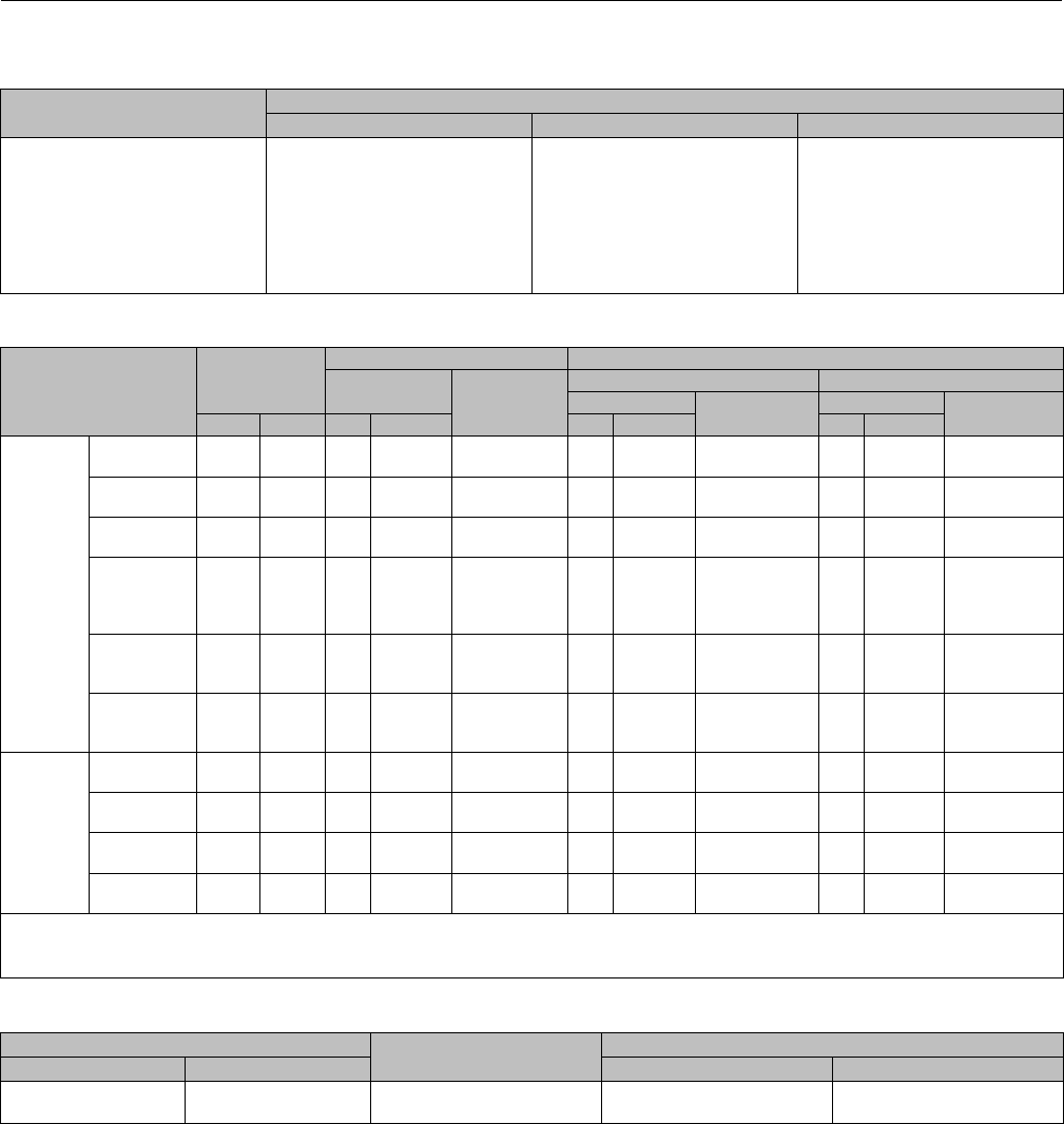
Instruction Manual
D100398X012
ET Valve
October 2014
39
Key 3* Cavitrol III Cage Assembly, 17-4PH stainless steel (H900)
ET
VALVE SIZE, NPS
STAGE
1 2 Characterized 2
1
1-1/2
2
2-1/2
3
4
6
8
38A1018X012
38A1019X012
38A1020X012
38A1021X012
38A1023X012
38A1025X012
38A1027X012
38A1029X012
24A5558X012
24A5559X012
24A3031X032
24A5560X012
23A9453X022
23A5817X032
23A5804X012
24A3020X032
24A5558X022
24A5559X022
24A3031X022
24A5560X022
23A9453X012
23A5817X022
23A5804X022
24A3020X042
Key 7* Fisher ET Valve Plug Stem, 316 stainless steel (not for Cavitrol III or Whisper Trim III cage)
VALVE
SIZE, NPS
STEM
DIAMETER &
VSC(1) SIZE
PLAIN BONNET(3) EXTENSION BONNET
Stem Length Part
Number
Style 1(4) Style 2
Stem Length Part
Number
Stem Length Part
Number
mm Inches mm Inches mm Inches mm Inches
Full
Capacity
1, 1-1/4,
or 1-1/2
9.5
12.7
3/8
1/2
225
300
8.875
11.8125
1U388835162
1U389035162
311
402
12.25
15.8125
1U217735162
1U217935162
405
473
15.9375
18.625
10A8823X022
1U218035162
212.7
19.1
1/2
3/4
311
372
12.25
14.625
1K586935162
1U226535162
413
483
16.25
19
1U226335162
1L400135162
614
---
24.1875
---
1U226435162
---
2-1/2 or 3 12.7
19.1
1/2
3/4
321
381
12.625
15
1U230535162
1U230835162
421
502
16.5625
19.75
1U230635162
1U444635162
624
---
24.5625
---
1U230735162
---
4
12.7
19.1
25.4(1)
25.4(2)
1/2
3/4
1(1)
1(2)
321
394
464
489
12.625
15.5
18.25
19.25
1U230535162
1K587735162
1K759035162
1U217535162
421
502
---
---
16.5625
19.75
---
---
1U230635162
1U444635162
---
---
624
694
---
---
24.5625
27.3125
---
---
1U230735162
1U240035162
---
---
6
19.1
25.4
31.8
3/4
1
1-1/4
403
499
508
15.875
19.625
20
1L996435162
1N704735162
1K415435162
511
630
656
20.125
24.8125
25.8125
1U507135162
1K785135162
1R562435162
699
---
---
27.5
---
---
1U524435162
---
---
8
19.1
25.4
31.8
3/4
1
1-1/4
492
614
705
19.375
24.1875
27.4375
1K588035162
1K7891X0012
1L268835162
533
614
705
21
24.1875
29.4375
1U928235162
1K7891X0012
1L268835162
---
---
---
---
---
---
---
---
---
Restricted
Capacity
1-1/2 x 1 9.5
12.7
3/8
1/2
241
311
9.375
12.25
1U223635162
1K586935162
324
413
12.75
16.25
1U227035162
1U226335162
418
486
16.4375
19.125
1U227235162
1U227335162
2x1or
2-1/2 x 1-1/2 12.7 1/2 300 11.8125 1U389035162 402 15.8125 1U217935162 605 23.8125 1U3893X0012
3x2 12.7
19.1
1/2
3/4
311
372
12.25
14.625
1K586935162
1U226535162
413
483
16.25
19
1U226335162
1L400135162
614
---
24.1875
---
1U226435162
---
4 x 2-1/2 12.7
19.1
1/2
3/4
321
381
12.625
15
1U230535162
1U230835162
421
502
16.5625
19.75
1U230635162
1U444635162
624
681
24.5625
26.8125
1U230735162
1U232335162
1. 667 actuator.
2. 657 or 585C Series actuator.
3. Plain bonnet is standard for NPS 8 cast iron and WCC valve bodies.
4. Style 1 extension bonnet is standard for NPS 8 316 SST valve bodies.
Key 7* Whisper Trim III Valve Plug Stem, 316 stainless steel (NPS 6 Fisher ET only)
STEM DIAMETER PLAIN BONNET EXTENSION BONNET
mm Inches Style 1 Style 2
19.1
25.4
3/4
1
1U294135162
1P847635162
1U928235162
1U627735162
1U6276X0012
———
*Recommended spare parts

Instruction Manual
D100398X012
ET Valve
October 2014
40
Key 7* 1-Stage Cavitrol III Valve Plug Stem (Fisher ET only)
VALVE SIZE,
NPS
TRAVEL ACTUATOR GROUP
(FROM PRECEDING
TABLE)
STEM DIAMETER 316 STAINLESS
STEEL
17-4PH STAINLESS
STEEL STEM
mm Inches mm Inches
119, 25 0.75, 1 112.7 1/2 1U389035162 1U3890X0062
1-1/2 19, 22 0.75, 0.875 112.7 1/2 1U389035162 1U3890X0062
226 1.125 1
1
12.7
19.1
1/2
3/4
1K586935162
1U226535162
10A8840XC82
1U226535382
2-1/2 38 1.5 1
1
12.7
19.1
1/2
3/4
1U230535162
1U230835162
1U2305X0012
1U2308X0082
338, 41 1.5, 1.625 1
1
12.7
19.1
1/2
3/4
1U230535162
1U230835162
1U2305X0012
1U2308X0082
4
51, 54
54
54
2, 2.125
2.125
2.125
1
402
403
19.1
19.1
19.1
3/4
3/4
3/4
1K587735162
1V142235162
1U293835162
1K5877X0022
1V1422X0042
1U2938X0062
51, 54 2, 2.125 100
101
25.4
25.4
1
1
1U217535162
1K759035162
1U217550372
1K7590X0012
6
51
57
51
57
2
2.25
2
2.25
100
100
100
100
25.4
25.4
31.8
31.8
1
1
1-1/4
1-1/4
1P847635162
1N704735162
1K415435162
1N920935162
11A3429X252
1N7047X0012
1K415435382
1N9209X0052
51, 57 2, 2.25 101
101
25.4
31.8
1
1-1/4
1P405135072
1K775335162
1P4051X0032
1K7753X0012
8
76, 86 3, 3.375 100, 101, 404
100, 101, 404
25.4
31.8
1
1-1/4
10A3282X012
1R489535162
10A3282X012
1R4895X0022
86 3.375 407
407
25.4
31.8
1
1-1/4
11A3429X012
1U9886X0012
1K7783X0052
1U9886X0152
Key 7* Valve Plug Stem for Bellows Seal Bonnet, 316 Stainless Steel
VALVE SIZE, NPS STEM DIAMETER STEM LENGTH PART NUMBER
ET EAT mm Inches mm Inches
1,
1-1/4, 1-1/2, or 1-1/2 X 1 1, 2, or 2 x 1 9.5
12.7
3/8
1/2
222
286
8.75
11.25
1R288535162
1R288835162
2, 2-1/2,
2-1/2 X 1-1/2, or 3 3or4 12.7 1/2 314 12.375 1U389235162
——— 3 x 1-1/2 12.7 1/2 295 11.625 1U388935162
2x1or3x2 4x2 12.7 1/2 305 12 1U389135162
4 6 12.7
19.1
1/2
3/4
327
387
12.875
15.25
2R369335072
1K587635162
4 x 2-1/2 6 x 2-1/2 12.7
19.1
1/2
3/4
327
375
12.875
14.75
2R369335072
1U389435162
6——— 19.1 3/4 387 15.25 1K587635162
*Recommended spare parts

Instruction Manual
D100398X012
ET Valve
October 2014
41
Key 9* Fisher EAT Liner
Liner
Material Valve Size, NPS CL150 Raised Face CL300 Raised Face CL600 Raised Face Socket Weld
Schedule
40 or 80
Butt Weld
416 stainless steel
(hardened)
1
2
2x1
3
3 x 1-1/2
4
4x2
6
6 x 2-1/2
1V560146172
1V560346172
1V560646172
2V561346172
2V560946172
2V562246172
2V561846172
2V563146172
2V562646172
1U384246172
1U384346172
1U385146172
2U384546172
2U385346172
2U384746172
2U385546172
2U384946172
2U385746172
1V560246172
1V560546172
1V387646172
2V561646172
2V545946172
2V561946172
2V561246172
2V562846172
2V562346172
1V560146172
1V560346172
1V560646172
---
---
---
---
---
---
1V560146172
1V560346172
1V560646172
2V561346172
2V560946172
2V562246172
2V561846172
2U384946172
2U385746172
316 stainless steel
1
2
2x1
3
3 x 1-1/2
4
4x2
6
6 x 2-1/2
1V560135072
1V560335072
1V560635072
2V561335072
2V560935072
2V562235072
2V561835072
2V563135072
2V562635072
1U384235072
1U384335072
1U385135072
2U384535072
2U385335072
2U384735072
2U385535072
2U384935072
2U385735072
1V560235072
1V560535072
1V387635072
2V561635072
2V545935072
2V561935072
2V561235072
2V562835072
2V562335072
1V560135072
1V560335072
1V560635072
---
---
---
---
---
---
1V560135072
1V560335072
1V560635072
2V561335072
2V560935072
2V562235072
2V561835072
2U384935072
2U385735072
Key 9* Metal-Seat Seat Ring (not for Whisper Trim III or Cavitrol III Cage)
VALVE SIZE, NPS 416
STAINLESS STEEL
(HARDENED)(1)
316 STAINLESS STEEL R30006
ET EAT
1, 1-1/4, or 2 x 1
1-1/2 x 1
1-1/2 or 2-1/2 x 1-1/2
2or3x2
2-1/2 or 4 x 2-1/2
3
4
6
8
1
2x1
2or3x1-1/2
4x2
3or6x2-1/2
4
6
---
---
1U222546172
1U222046172
1U221946172
1U222646172
1U222746172
1U222846172
1U222946172
1U508046172
20A3260X012
1U222535072
1U222035072
1U221935072
1U222635072
1U222735072
1U222835072
1U222933092
1U508033092
20A3260X022
1U222539102
1U222039102
1U221939102
1U222639102
1U222739102
1U222839102
1U222939102
1U508039102
20A3260X152
1. 410 stainless steel (CA15) is used for NPS 6 and 8 full-sized and restricted-trim valves.
Key 9* Cavitrol III Seat Ring (Fisher ET only)
VALVE SIZE, NPS
1-STAGE CAGE 2-STAGE CAGE
17-4PH
Stainless Steel Alloy 6 (Cast) 17-4PH
Stainless Steel
316 Stainless Steel
w/CoCr-A Seat & Bore
1
1-1/2
2
2-1/2
3
4
6
8
23A7567X012
23A7568X012
23A7569X012
24A1586X012
24A3016X012
24A1135X012
23A5820X032
23A9445X022
23A7567X022
23A7568X022
23A7569X022
24A1586X022
24A3016X022
24A1135X022
23A5820X012
23A9445X032
24A5231X012
24A5232X012
24A3039X012
24A5233X012
23A9450X012
23A5813X012
23A5802X022
24A3021X022
24A5239X012
24A5240X012
24A5241X012
24A5242X012
24A5243X012
24A5244X012
24A5245X012
24A5246X012
Key 9* Whisper Trim III Seat Ring (NPS 6 Fisher ET only)
410 Stainless Steel 316 Stainless Steel 316 Stainless Steel w/
CoCr-A Seat
21A9794X012 21A9794X022 21A9795X012
*Recommended spare parts

Instruction Manual
D100398X012
ET Valve
October 2014
42
Gasket Descriptions
KEY NUMBER DESCRIPTION
MATERIAL
FGM
-198_to 593_C(-325_to 1100_F)
10(1) Bonnet Gasket
Graphite/S31600
11 Cage Gasket
13 Seat Ring or Liner Gasket
14 or 20 Adapter Gasket
12 Spiral-Wound Gasket N06600/Graphite
27 or 51 Shim S31600 (316 SST)
1. 2 req'd for 2-stage Cavitrol III cage.
Keys 10*, 11*, 12*, 13*, 14*, 20*, 27*, and 51* Gaskets and Shims
Valve Size, NPS
Standard Trim Cage
Whisper Trim I Cage
Cavitrol III - 1 Stage Cage
Cavitrol III - 2 Stage Cage
Whisper Trim III Cage
WhisperFlo Cage
VALVE SIZE, NPS
Standard Trim Cage
Whisper Trim I Cage
Cavitrol III - 1 Stage Cage
Cavitrol III - 2 Stage Cage
Whisper Trim III Cage
WhisperFlo Cage
ET EAT Key
Number
-198 to 593_C
(-325 to 1100_F)
Key
Number
-198 to 593_C
(-325 to 1100_F) ET EAT Key
Number
-198 to 593_C
(-325 to 1100_F)
Key
Number
-198 to 593_C
(-325 to 1100_F)
1or
1-1/4 1
Set
10
12
13
27 or 51
RGASKETX162
1R2859X0042
1R286099442
1R2862X0062
16A1936X012
Set
10
12
13
51
RGASKETX422
1R2859X0042(qty 2)
1R286099442
1R2862X0062
16A1936X012
3 4
Set
10
12
13
27 or 51
RGASKETX202
1R3484X0042
1R348299442
1R3481X0052
16A1940X012
Set
10
12
13
51
RGASKETX462
1R3484X0042(qty 2)
1R348299442
1R3481X0052
16A1940X012
1-1/2 2
Set
10
12
13
27 or 51
RGASKETX172
1R3101X0032
1R309999442
1R3098X0052
16A1937X012
Set
10
12
13
51
RGASKETX432
1R3101X0032(qty 2)
1R309999442
1R3098X0052
16A1937X012
3x2 4x2
Set
10
11
12
13
14
27 or 51
RGASKETX272
1R3484X0042
1R3298X0032
1R329799442
1R3296X0042
1R3481X0052
16A1938X012
--- ---
1-1/2 x 1 2x1
Set
10
11
12
13
20
27 or 51
RGASKETX242
1R3101X0032
1R2861X0042
1R286099442
1R3098X0052
1U2152X0042
16A1936X012
--- --- 4 6
Set
10
12
13
27 or 51
RGASKETX212
1R3724X0042
1R372299442
1J5047X0062
16A1941X012
Set
10
12
13
51
RGASKETX472
1R3724X0042(qty 2)
1R372299442
1J5047X0062
16A1941X012
2---
Set
10
12
13
51
RGASKETX182
1R3299X0042
1R329799442
1R3296X0042
16A1938X012
Set
10
12
13
51
RGASKETX442
1R3299X0042(qty 2)
1R329799442
1R3296X0042
16A1938X012
4x
2-1/2 6 x 2-1/2
Set
10
11
12
13
14
27 or 51
RGASKETX282
1R3724X0042
1R3846X0042
1R384599442
1R3844X0052
1J5047X0062
16A1939X012
--- ---
2x1 ---
Set
10
11
12
13
14
51
RGASKETX252
1R3299X0042
1R2861X0042
1R286099442
1R2862X0062
1R3296X0042
16A1936X012
--- --- 6---
Set
10
12
13
51
RGASKETX222
1U5081X0052
1U508599442
1U5086X0032
16A1942X012
Set
10
12
13
51
RGASKETX482
1U5081X0052(qty 2)
1U508599442
1U5086X0032
16A1942X012
2-1/2 3
Set
10
12
13
27 or 51
RGASKETX192
1R3847X0032
1R384599442
1R3844X0052
16A1939X012
Set
10
12
13
51
RGASKETX452
1R3847X0032(qty 2)
1R384599442
1R3844X0052
16A1939X012
8---
Set
10
13
RGASKETX232
10A3265X112
10A3266X082
Set
10
13
10A3265X152
10A3265X112(qty 2)
10A3266X082
2-1/2 x
1-1/2 3 x 1-1/2
Set
10
11
12
13
14
27 or 51
RGASKETX262
1R3847X0032
1R3100X0032
1R309999442
1R3098X0052
1R3844X0052
16A1937X012
--- ---
*Recommended spare parts
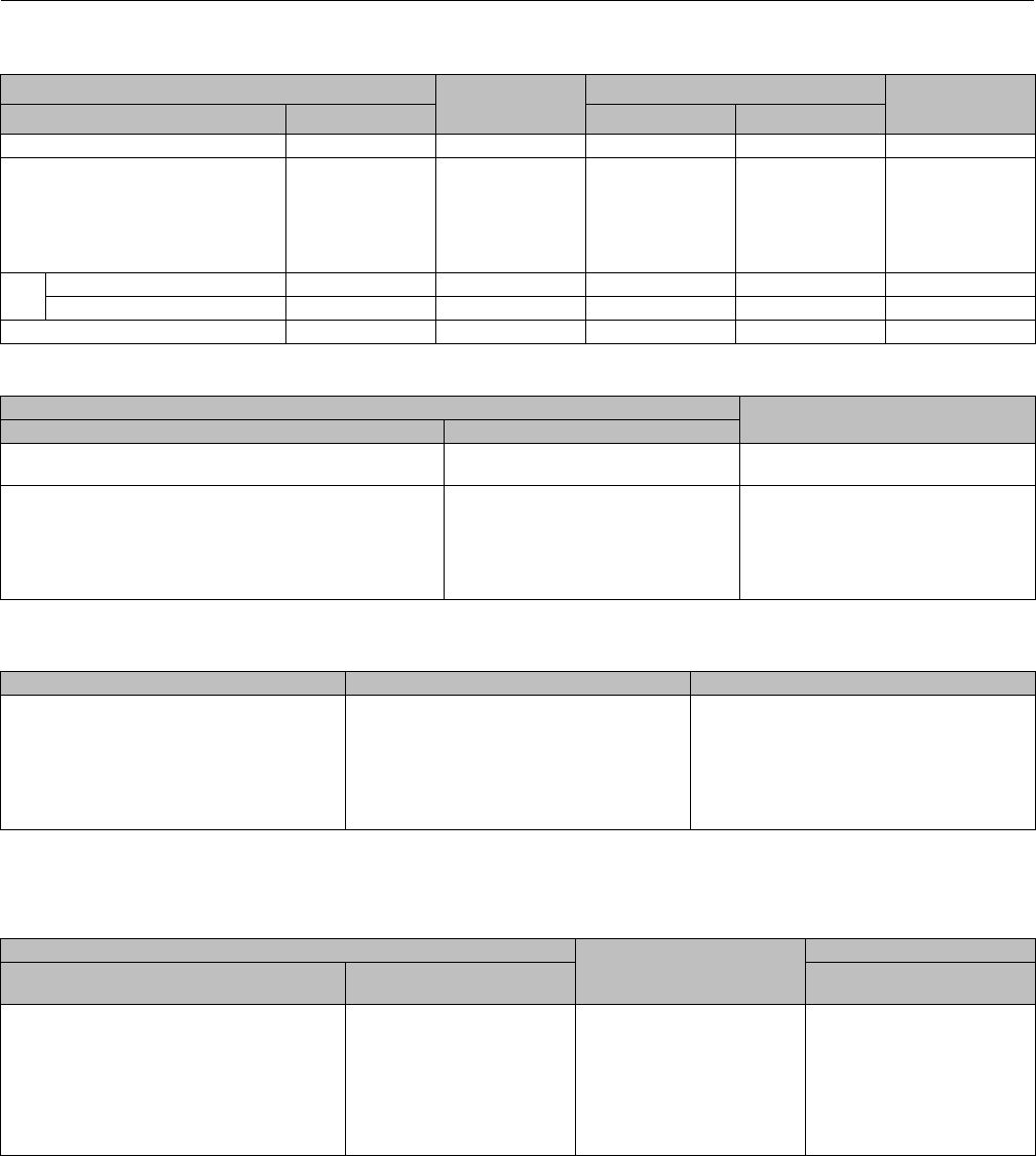
Instruction Manual
D100398X012
ET Valve
October 2014
43
Key 21*, 22*, and 23* PTFE Seat Disk Retainer, Disk Seat, and Disk
VALVE SIZE, NPS KEY 21 DISK
RETAINER, 316
STAINLESS STEEL
KEY 22 DISK SEAT KEY 23 DISK, PTFE
-73 TO 204_C (-100
TO 400_F)
ET EAT 316 Stainless Steel Alloy 6 (Cast)
1, 1-1/4, or 2 x 1 11V710035072 1V710235072 1V710239102 1V710106242
1-1/2 or 2-1/2 x 1-1/2
1-1/2 x 1
2or3x2
2-1/2 or 4 x 2-1/2
3
4
2or3x1-1/2
2x1
4x2
3or6x2-1/2
4
6
1V710335072
1V712135072
1V710835072
1V710935072
1V711235072
1V711533092
1V710535072
1V712235072
1V710635072
1V711135072
1V711435072
1V711733092
1V710539102
1V712239102
1V710639102
1V711139102
1V711439102
1V711739102
1V710406242
1V710106242
1V710706242
1V711006242
1V711306242
1V711606242
6All except Whisper Trim III cage ——— 1V711833092 1V712033092 1V7120X0012 1V711906242
Whisper Trim III cage ——— 23A4937X012 23A4938X012 ——— 13A4936X012
8——— 10A4466X012 20A4467X012 20A4467X022 20A4468X012
Key 27* Retaining Ring for Spring-Loaded Seal Ring, 302 SST
VALVE SIZE, NPS PART NUMBER
ET EAT
1, 1-1/4
1-1/2 x 1, or 2 x 1 1or2x1 10A4211X012
1-1/2 or 2-1/2 x 1-1/2
2or3x2
2-1/2 or 4 x 2-1/2
3
4
6 (Whisper Trim III only)
2or3x1-1/2
4x2
3or6x2-1/2
4
6
———
10A4220X012
10A4210X012
10A4219X012
10A5350X012
10A4225X012
10A5410X012
Key 27* Cavitrol III Retaining Ring for NPS 1 through 6 Fisher ET only, 302 SST
VALVE SIZE, NPS 1-STAGE CAGE 2-STAGE CAGE
1
1-1/2
2
2-1/2
3
4
6
10A4211X012
10A4220X012
10A4210X012
10A4219X012
10A5350X012
10A4225X012
None required
11A3405X012
10A4211X012
10A4220X012
10A4210X012
10A4219X012
10A4219X012
10A5410X012
Key 24* Seal Ring (Fisher EAT)
Key 28* Seal Ring (Fisher ET) (not for Cavitrol III or Whisper Trim III Construction)
VALVE SIZE, NPS STANDARD, CARBON FILLED
PTFE
SPRING-LOADED
ET EAT PTFE -73 to 232_C
(-100 to 450_F)
1, 1-1/4, 1-1/2 x 1, or 2 x 1
1-1/2 or 2-1/2 x 1-1/2
2or3x2
2-1/2 or 4 x 2-1/2
3
4
6
8
1or2x1
2or3x1-1/2
4x2
3x2or6x2-1/2
4
6
———
———
1V659105092
1V659305092
1V550805092
1V659505092
1V659705092
1V659905092
1V660105092
———
10A4207X012
10A4216X012
10A4206X012
10A4215X012
10A5351X022
10A4223X012
10A2643X022
10A3261X012
*Recommended spare parts
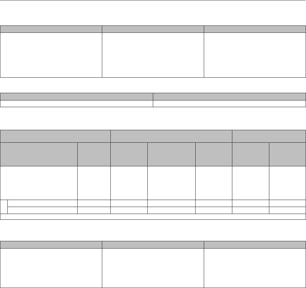
Instruction Manual
D100398X012
ET Valve
October 2014
44
Key 28* Cavitrol III Seal Ring for Fisher ET only, spring loaded PTFE
VALVE SIZE, NPS 1-STAGE CAGE 2-STAGE CAGE
1
1-1/2
2
2-1/2
3
4
6
8
10A4207X012
10A4216X012
10A4206X012
10A4215X012
10A5351X022
10A4223X012
10A2643X022
10A3261X012
11A3407X042
10A4207X012
10A4216X012
10A4206X012
10A4215X012
10A4215X012
10A5411X022
10A2643X022
Key 28* Whisper Trim III Seal (NPS 6 Fisher ET only)
CARBON FILLED PTFE SPRING LOADED PTFE
11A9729X012 10A5411X022
Key 25* Backup Ring (Fisher EAT)
Key 29* Backup Ring (Fisher ET) (not for Cavitrol III or NPS 8 ET)
VALVE SIZE, NPS STANDARD CONSTRUCTION SPRING LOADED SEAL
CONSTRUCTION
ET EAT
Nitrile
-34 to 93_C
(-30 to 200_F)
Fluorocarbon(1)
-18 to 204_C
(-0 to 400_F)
Ethylene
Propylene
-40 to 232_C
(-40 to 450_F)
416 Stainless
Steel
316 Stainless
Steel
1, 1-1/4, 1-1/2 x 1, or 2 x 1
1-1/2 or 2-1/2 x 1-1/2
2or3x2
2-1/2 or 4 x 2-1/2
3
4
1or2x1
2or3x1-1/2
4x2
3or6x2-1/2
4
6
1V659003052
1V659203052
1V550703052
1V659403052
1V659603052
1V659803052
1V659005292
1V659205292
1V550705292
1V659405292
1V659605292
1V659805292
1V6590X0042
1V6592X0032
1V5507X0042
1V6594X0032
1V6596X0032
1V6598X0022
10A4209X012
10A4218X022
10A4208X012
10A4217X012
10A5349X012
10A4224X012
10A4209X022
10A4218X012
10A4208X022
10A4217X022
10A5349X022
10A4224X022
6All except Whisper Trim III cage ——— 1V660003052 1V660005292 1V6600X0022 ——— ———
Whisper Trim III cage ——— 11A9728X022 11A9728X012 11A9728X042 12A3332X012 12A3332X022
1. Not for use with steam or ammonia. Not recommended for water above 82_C (180_F).
Key 29* Cavitrol III Backup Ring, 416 Stainless Steel (not for NPS 8 Fisher ET)
VALVE SIZE, NPS 1-STAGE CAGE 2-STAGE CAGE
1
1-1/2
2
2-1/2
3
4
6
10A4209X012
10A4218X022
10A4208X012
10A4217X012
10A5349X012
10A4224X012
None required
11A3404X012
10A4209X022
10A4218X022
10A4208X012
10A4217X012
10A4217X012
10A5409X012
*Recommended spare parts

Instruction Manual
D100398X012
ET Valve
October 2014
45
Keys 3*, 9*, 2*, 28*, 63*, 29*, and 27* TSO Trim Parts for Fisher ET Valves
VALVE
SIZE,
NPS
PORT,
INCH
TRAVEL,
INCH TRIM
STEM
DIAMETER ACTUATOR
GROUP
CHARAC-
TERISTIC
KEY 3 KEY 3 KEY 9 KEY 2
mm Inch Cage
Full 2-Stage
Cage
Characterized
2-Stage
Seat Ring Plug / Stem
Assembly
32.6875 3
810
816 12.7 1/2 1&400
Cavitrol III
23A9453X022 23A9453X012 28B1302X012
28B1303X012
28B1306X012
28B1306X022
810
816 19.1 3/4 100 & 101 23A9453X022 23A9453X012 28B1302X012
28B1303X012
27B6604X112
27B6604X122
42.6875
3
810 19.1 3/4
1, 402, 403
Cavitrol III 23A5817X032 23A5817X022 28B1307X012 28B1310X012
4401, 403
4402 28B1310X022
VALVE
SIZE,
NPS
PORT,
INCH
TRAVEL,
INCH TRIM
STEM
DIAMETER ACTUATOR
GROUP
CHARAC-
TERISTIC
KEY 28 KEY 63 KEY 29 KEY 27
mm Inch Seal Ring Anti-Extrusion
Ring Back-Up Ring Retaining Ring
32.6875 3
810
816 12.7 1/2 1&400
Cavitrol III 10A4215X102 22B2617X012
10A4217X012
10A4217X022
10A4219X012
10A4219X082
810
816 19.1 3/4 100 & 101 10A4217X012
10A4217X022
10A4219X012
10A4219X052
42.6875
3
810 19.1 3/4
1, 402, 403
Cavitrol III 10A4215X102 22B2617X012 10A4217X012 10A4219X012
4401, 403
4402
Keys 3*, 7*, 24*, 63*, 25*, and 27* TSO Trim Parts for Fisher ET and EAT Valves(1)
VALVE SIZE, NPS PORT TRAVEL STEM
DIAMETER CHARAC-
TERISTIC
KEY 3 KEY 7 KEY 24 KEY 63 KEY 25 KEY 27
ET EAT Inch Inch mm Inch Cage Plug/Stem
Assembly Seal Ring
Anti-
Extrusion
Ring
Back-Up Ring Retaining
Ring
3 4 3.25 1.5 12.7 1/2
Linear
Equal %
Quick Open
2U232433272
2U232133272
2U231833272
27B9567X012 10A5351X112 23B6126X012 10A5349X012 10A5350X012
4 6 4.1875 219.1 3/4
Linear
Equal %
Quick Open
2U236633272
2U236333272
2U236033272
38B0282X012 10A4223X142 21B9341X012 10A4224X012 10A4225X012
1. Trim is 812.
Key 9* TSO Trim Parts for Fisher ET and EAT Valves(1)
VALVE SIZE, NPS PORT,
INCH
KEY 9
Seat Ring
Seat and Liner
ET EAT CL150
Raised Face
CL300
Raised Face
CL600
Raised Face
Schedule 40 or 80
ButtWeld
3 4 3.25 37B9563X012 38B0273X012 38B0273X022 38B0273X032 38B0273X012
4 6 4.1875 38B0276X012 38B0277X012 38B0276X022 38B0276X032 38B0276X022
1. Trim is 812.
*Recommended spare parts

Instruction Manual
D100398X012
ET Valve
October 2014
46
Keys 63*, 28*, 29*, 27*, 2*, and 9* Fisher ET Full Capacity Trim above 232_C(450_F)
using PEEK Anti-Extrusion Rings
VALVE
SIZE,
NPS
PORT
Use w/
Cage/See
Footnote
KEY 63 KEY 28 KEY 29 KEY 27 KEY 2 STEM CONN
DIAMETER,
INCHES
KEY 9
Anti-Extrusion
Ring Seal Ring Back-Up Ring Retaining Ring Plug(1) Seat Ring(1)
11.3125 A23B6125X012 10A4207X032 10A4209X012 10A4211X012 33B6091X012 0.375 21B3686X012
1-1/2 1.875 A22B4694X012 10A4216X032 10A4218X022 10A4220X012 33B6093X012
33B6094X012
0.375
0.5 21B6970X012
22.3125 A21B9340X012 10A4206X032 10A4208X012 10A4210X012 33B6097X012
33B6098X012
0.5
0.75 10B8254X012
2-1/2 2.875 A22B2617X012 10A4215X032 10A4217X012 10A4219X012 33B6109X012
33B6110X012
0.5
0.75 21B3687X012
33.4375 A23B6126X012 10A5351X062 10A5349X012 10A5350X012 33B6105X012
33B6106X012
0.5
0.75 23B6127X012
44.375 A21B9341X012 10A4223X032 10A4224X012 10A4225X012
33B6101X012
33B6102X012
33B6111X012
0.5
0.75
1
23B6128X012
6 7 A 22B5998X012 10A2643X032 12B5997X012 14A4652X012 33B6115X012
33B6116X012
0.75
129A9703X012
65.375 C21B9342X012 10A5411X032 12A3332X012 10A5410X012 33B6134X012
33B6136X012
0.75
133B6146X012
8 8 B 22B9203X012 10A3261X032 11B8325X022 11B8322X012
33B6119X012
33B6120X012
33B6121X012
0.75
1
1.25
29A9704X012
A–Cages - Quick opening, equal percentage, linear, Whisper I.
B–Cages - Equal percentage, linear - plug & seat ring material CA15 (cast 410).
C–Cages - Whisper III - plug material 17-4PH H900 - seat ring material forged F6A (SST).
1. Seat rings with wide bevel seat and plugs with radius seat.
Keys 63*, 28*, 29*, 27*, 2*, and 9* Fisher ET Restricted Trim above 232_C (450_F) using PEEK Anti-Extrusion Rings
VALVE SIZE, NPS PORT
KEY 63 KEY 28 KEY 29 KEY 27 KEY 2 STEM CONN
DIAMETER,
INCHES
KEY 9
Anti-Extrusion
Ring Seal Ring Back-Up Ring Retaining Ring Plug(1) Seat Ring(1)
1-1/2 x 1 1.3125 23B6125X012 10A4207X032 10A4209X012 10A4211X012 33B6091X012 0.375 22B3550X012
2-1/2 x 1-1/2 1.875 22B4694X012 10A4216X032 10A4218X022 10A4220X012 33B6094X012 0.5 21B6970X012
3x2 2.3125 21B9340X012 10A4206X032 10A4208X012 10A4210X012 33B6097X012
33B6098X012
0.5
0.75 10B8254X012
4 x 2-1/2 2.875 22B2617X012 10A4215X032 10A4217X012 10A4219X012 33B6109X012
33B6110X012
0.5
0.75 21B3687X012
Cages - Quick opening, equal percentage, linear, Whisper I.
1. Seat rings with wide bevel seat and plugs with radius seat.
*Recommended spare parts

Instruction Manual
D100398X012
ET Valve
October 2014
47

Instruction Manual
D100398X012
ET Valve
October 2014
48
Emerson Process Management
Marshalltown, Iowa 50158 USA
Sorocaba, 18087 Brazil
Chatham, Kent ME4 4QZ UK
Dubai, United Arab Emirates
Singapore 128461 Singapore
www.Fisher.com
The contents of this publication are presented for informational purposes only, and while every effort has been made to ensure their accuracy, they arenot
to be construed as warranties or guarantees, express or implied, regarding the products or services described herein or their use or applicability. All sales are
governed by our terms and conditions, which are available upon request. We reserve the right to modify or improve the designs or specifications of such
products at any time without notice.
E1973, 2014 Fisher Controls International LLC. All rights reserved.
Fisher,easy-e,Cavitrol,ENVIRO-SEAL,WhisperFlo,andWhisperTrimare marks owned by one of the companies in the Emerson Process Management
business unit of Emerson Electric Co. Emerson Process Management, Emerson, and the Emerson logo are trademarks and service marks of Emerson Electric
Co. All other marks are the property of their respective owners.
Neither Emerson, Emerson Process Management, nor any of their affiliated entities assumes responsibility for the selection, use or maintenance
of any product. Responsibility for proper selection, use, and maintenance of any product remains solely with the purchaser and end user.
