Emerson Fisher Fieldvuedvc6200F Digital Valve Controller Instruction Manual D103412X012_Jan15_AQ
2015-03-30
: Emerson Emerson-Fisher-Fieldvuedvc6200F-Digital-Valve-Controller-Instruction-Manual-681776 emerson-fisher-fieldvuedvc6200f-digital-valve-controller-instruction-manual-681776 emerson pdf
Open the PDF directly: View PDF ![]() .
.
Page Count: 314 [warning: Documents this large are best viewed by clicking the View PDF Link!]
www.Fisher.com
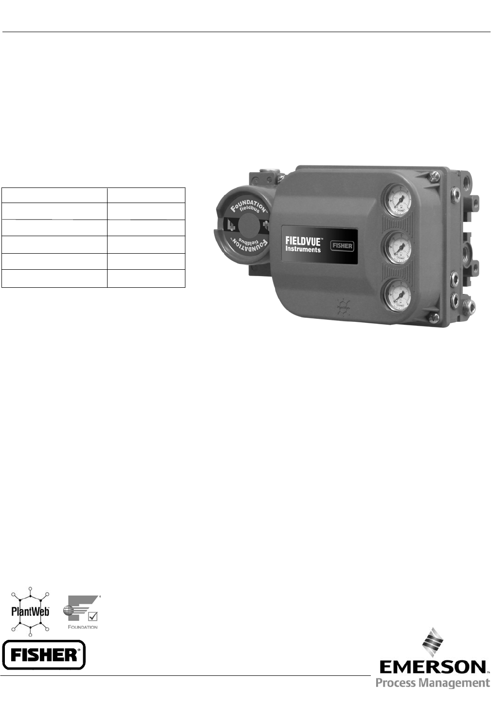
Fisherr FIELDVUE™ DVC6200f Digital Valve
Controller for FOUNDATION™ fieldbus
Instruction Manual
D103412X012
DVC6200f Digital Valve Controller
January 2015
This manual applies to:
Device Type 4602
Device Revision 2
Hardware Revision 8
Firmware Revision 2.0
DD Revision 2 and 3
Instrument Level FD, PD, AD

The FIELDVUE DVC6200f Digital Valve Controller is a core component of the PlantWeb™ digital
plant architecture. The digital valve controller powers PlantWeb by capturing and delivering valve
diagnostic data. Coupled with ValveLink™ software, the DVC6200 provides users with an accurate
picture of valve performance, including actual stem position, instrument input signal, and
pneumatic pressure to the actuator. Using this information, the digital valve controller diagnoses
not only itself, but also the valve and actuator to which it is mounted.

Instruction Manual
D103412X012
DVC6200f Digital Valve Controller
January 2015
1
Contents
Section 1 Introduction and
Specifications 3......................
Installation, Pneumatic and Electrical Connections,
and Initial Configuration 3.....................
Scope of Manual 3..............................
Instrument Description 3........................
Using this Manual 4.............................
Specifications 6................................
Related Information 10..........................
Educational Services 10..........................
Section 2 Wiring Practices 11.............
Quick Connect Cable Entry 11....................
Communication Connections 12..................
Simulate Enable Jumper 13.......................
Section 3 Basic Setup 15.................
Basic Setup 15.................................
Transducer Block Mode 15......................
Protection 15.................................
Device Setup 16...............................
Performance Tuner 20.........................
Section 4 Detailed Setup 21..............
Resource Block 21..............................
Transducer Block 38............................
Analog Output Function Block 89.................
Proportional/Integral/Derivative
Function Block 102...........................
Input Selector Function Block 121.................
Output Splitter Function Block 136................
Analog Input Function Block 147..................
Mulitple Analog Input Function Block 159..........
Discrete Output Function Block 165...............
Discrete Input Function Block 177.................
Section 5 Calibration 189................
Calibration Overview 189........................
Calibration 189.................................
Auto 190.....................................
Manual 190..................................
Relay 191....................................
Supply Pressure Sensor 192.....................
Pressure A or B Sensor 193......................
Section 6 Viewing Device
Variables and Diagnostics 195..........
View Lists 195..................................
Resource Block 195.............................
Device Diagnostics 196.........................
Device Variables 198...........................
Transducer Block 199...........................
Device Diagnostics 200.........................
Device Variables 205...........................
Figure 1‐1. FIELDVUE DVC6200f Digital Valve
Controller
W9713_fieldbus
Section 7 Maintenance and
Troubleshooting 209..................
Replacing the Magnetic Feedback Assembly 210.....
Module Base Maintenance 210....................
Tools Required 210............................
Component Replacement 211...................
Removing the Module Base 211.................
Replacing the Module Base 212..................
Submodule Maintenance 213.....................
I/P Converter 213..............................
Printed Wiring Board (PWB) Assembly 215.........
Pneumatic Relay 216...........................
Gauges, Pipe Plugs or Tire Valves 217.............
Terminal Box 217...............................
Removing the Terminal Box 217.................
Replacing the Terminal Box 218..................
Stroking the Digital Valve Controller Output 218.....
Instrument Troubleshooting 219..................
Section 8 Parts 225.....................
Parts Ordering 225..............................
Parts Kits 225..................................
Parts List 226..................................
Housing 226..................................
Common Parts 226............................
Module Base 227..............................
I/P Converter Assembly 227.....................
Relay 227....................................
Terminal Box 227..............................
PWB Assembly 228............................

Instruction Manual
D103412X012
DVC6200f Digital Valve Controller
January 2015
2
Pressure Gauges, Pipe Plugs, or
Tire Valve Assemblies 228....................
DVC6215 Feedback Unit 228....................
Appendix A Principle of Operation 235.....
Digital Valve Controller Operation 235.............
Appendix B Field Communicator
Menu Tree 237.......................
Appendix C PlantWeb Alerts 251..........
Alert Conditions 251............................
PlantWeb Alerts 251............................
Alert Handling 251............................
Alert Reporting 253............................
PlantWeb Alerts Set Block Status 253.............
Setting PlantWeb Alerts 253......................
Using PlantWeb Alerts 253.......................
Appendix D FOUNDATION Fieldbus
Communication 263..................
Function Block Overview 263.....................
Function Blocks 263...........................
Instrument Specific Blocks 264..................
Resource Blocks 264...........................
Transducer Blocks 264.........................
Block Modes 265...............................
Explanation of Modes 266......................
Examples of Modes for Various
Operation Statuses 267......................
Device Descriptions 267.........................
Transducer Block Status and Limit Propagation 267..
Status Propagation 268........................
Limit Propagation 268..........................
Network Communication 269....................
Device Addressing 269.........................
Link Active Scheduler 269.......................
Device Communications 270....................
Scheduled Transfers 270....................
Unscheduled Transfers 271..................
Function Block Scheduling 272..................
Network Management 272.......................
Appendix E Device Description
Installation 273......................
Overview 273..................................
Device Descriptions and Methods 274.............
Installing DD on a DeltaV
ProfessionalPLUS Workstation 274................
Installing DDs on Other Fieldbus Host Systems 276...
Displaying the Device Description Revision 277......
Appendix F Operating with a
DeltaV System 279...................
Getting Started 279.............................
Transducer Block Parameter -
Configuration Index 280.......................
Resource Block Parameter - Configuration Index 285.
Introduction 286...............................
Software Functionality/System Requirements 286...
Using AMS Device Manager 286...................
Methods 288..................................
Accessing Parameters 288.......................
Bringing the Device On‐Line 291..................
PlantWeb Alerts 291............................
Setting up PlantWeb Alerts 291..................
Glossary 297...........................
Index 301.............................

Instruction Manual
D103412X012
Introduction and Specifications
January 2015
3
Section 1 Introduction and Specifications
Installation, Pneumatic and Electrical Connections,
and Initial Configuration
Refer to the DVC6200 Series Quick Start Guide (D103556X012) for DVC6200
installation, connection, and initial configuration information. If a copy of this quick
start guide is needed scan or click the QR code at the right, contact your Emerson
Process Management sales office, or visit our website at www.Fisher.com.
Scope of Manual
This instruction manual is a supplement to the quick start guide that ships with every instrument. This instruction
manual includes product specifications, supplementary installation information, reference materials, custom setup
information, maintenance procedures, and replacement part details for the FIELDVUE DVC6200f digital valve
controller.
Note
All references to the DVC6200f digital valve controller include the DVC6205f base unit unless otherwise indicated.
This manual describes device setup using the 475 or 375 Field Communicator. For information on using Fisher
ValveLink software with the instrument, refer to the appropriate user guide or help.
Do not install, operate, or maintain a DVC6200f digital valve controller without being fully trained and qualified in
valve, actuator, and accessory installation, operation, and maintenance. To avoid personal injury or property damage,
it is important to carefully read, understand, and follow all of the contents of this manual, including all safety cautions
and warnings. If you have any questions about these instructions, contact your Emerson Process Management sales
office before proceeding.
Instrument Description
DVC6200f digital valve controllers for FOUNDATION fieldbus are communicating, microprocessor‐based instruments. In
addition to the traditional function of converting a digital signal to a pneumatic output pressure, the DVC6200f digital
valve controller, using FOUNDATION fieldbus communications protocol, gives easy access to information critical to
process operation as well as process control. This can be done using a DeltaV console, another FOUNDATION fieldbus
system console, or with ValveLink software version 10.2 or later.
Using a compatible fieldbus configuration device, you can obtain information about the health of the instrument, the
actuator, and the valve. You can also obtain asset information about the actuator or valve manufacturer, model, and
serial number. You can set input and output configuration parameters and calibrate the instrument.
Using the FOUNDATION fieldbus protocol, information from the instrument can be integrated into control systems.
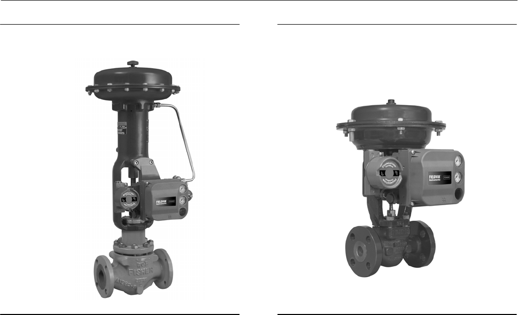
DVC6200f digital valve controllers can be mounted on single or double‐acting sliding‐stem actuators, as shown in
figure 1‐2, or on rotary actuators. It can also be integrally mounted to the Fisher GX control valve and actuator system,
as shown in figure 1‐3. The DVC6200f mounts on most Fisher and other manufacturers' rotary and sliding‐stem
actuators.
Scan or click
to access
field support
Instruction Manual
D103412X012
Introduction and Specifications
January 2015
4
Figure 1‐2 FIELDVUE DVC6200f Digital Valve
Controller Mounted on a Fisher Sliding‐Stem Valve
Actuator
W9643_fieldbus
Figure 1‐3. FIELDVUE DVC6200f Digital Valve
Controller Integrally Mounted to a Fisher GX Control
Valve and Actuator System
W9616_fieldbus
DVC6200f digital valve controllers are available with several selections of control and diagnostic capability. Control
selections include:
Standard Control (SC)— Digital valve controllers with Standard Control have the AO, PID, ISEL, OS, AI, MAI, DO, and
four DI function blocks in addition to the resource and transducer blocks.
Fieldbus Control (FC)—Digital valve controllers with Fieldbus Control have the AO function block in addition to the
resource and transducer blocks.
Fieldbus Logic (FL)—Digital valve controllers with Fieldbus Logic have the DO, and four DI function blocks, in
addition to the resource and transducer block.
The diagnostic capabilities include:
Performance Diagnostics (PD)
Advanced Diagnostics (AD)
Fieldbus Diagnostics (FD)
Performance and Advanced Diagnostics are available with ValveLink software. They provide visibility to instrument
alerts. Fieldbus Diagnostics can be viewed with any host system.

Instruction Manual
D103412X012
Introduction and Specifications
January 2015
5
Instrument Blocks
The digital valve controller is a block‐based device. For detailed information on the blocks within the digital valve
controller, see the Detailed Setup section of this manual.
The DVC6200f digital valve controller includes the resource and transducer block:
Resource Block—The resource block contains the hardware specific characteristics associated with a device; it has
no input or output parameters. The resource block monitors and controls the general operation of other blocks
within the device. For example, when the mode of the resource block is Out of Service, it impacts all function
blocks.
Transducer Block—The transducer block connects the analog output function block to the I/P converter, relay, and
travel sensor hardware within the digital valve controller.
Function Blocks
In addition to the resource and transducer block, the digital valve controller may contain the following function blocks.
For additional information on function blocks, refer to Appendix D, FOUNDATION fieldbus Communication.
Analog Output (AO) Function Block—The analog output function block accepts the output from another function
block (such as a PID block) and transfers it as an actuator control signal to the transducer block. If the DO block is
selected, the AO block is not functional.
Proportional‐Integral‐Derivative (PID) Function Block—The PID function block performs
proportional‐plus‐integral‐plus‐derivative control.
Input Selector (ISEL) Function Block—The input selector function block selects from up to four inputs and may
provide the selected signal as input to the PID block. The input selection can be configured to select the first good
input signal; a maximum, minimum or average value; or a hot spare.
Output Splitter (OS) Function Block—The output splitter function block accepts the output from another function
block (such as a PID block) and creates two outputs that are scaled or split, according to the user configuration. This
block is typically used for split ranging of two control valves.
Analog Input (AI) Function Block—The analog input function block monitors the signal from a DVC6200f sensor or
internal measurement and provides it to another block.
Multiple Analog Input (MAI) Function Block—The Multiple Analog Input (MAI) function block has the ability to
process up to eight DVC6200f measurements and make them available to other function blocks.
Discrete Output (DO) Function Block—The discrete output function block processes a discrete set point and sends it
to a specified output channel, which can be transferred to the transducer block for actuator control. In the digital
valve controller, the discrete output block provides both normal open/closed control and the ability to position the
valve in 5% increments for course throttling applications. If the AO block is selected, the DO block is not functional.
Discrete Input (DI) Function Block—The discrete input function block processes a single discrete input from a
DVC6200f and makes it available to other function blocks. In the digital valve controller, the discrete input function
block can provide limit switch functionality and valve position proximity detection.

Instruction Manual
D103412X012
Introduction and Specifications
January 2015
6
Using This Manual
Navigation paths and fast‐key sequences are included for procedures and parameters that can be accessed using the
Field Communicator.
For example, to access Resource Block Mode:
Field Communicator RB > Configure/Setup > Setup > Resource Block Mode
An overview of the resource and transducer block menu structures are shown in Appendix B. Menu structures for the
function blocks are included with each function block section in Detailed Setup.
Throughout this document, parameters are typically referred to by their common name or label, followed by the
parameter name and index number; for example, Write Priority (WRITE_PRI [39]). However, not all interface systems
support the use of the parameter label and instead use only the Parameter Name, followed by the index number, when
referring to the block parameters.
Specifications
Specifications for the DVC6200f digital valve controller are shown in table 1‐1.

Instruction Manual
D103412X012
Introduction and Specifications
January 2015
7
Table 1‐1. Specifications
Available Mounting
DVC6200f digital valve controller and DVC6215
feedback unit: Integral mounting to the Fisher GX
Control Valve and Actuator System Integral
mounting to Fisher rotary actuators, Sliding‐stem
linear applications Quarter‐turn rotary applications
DVC6205f base unit for 2 inch pipestand or wall
mounting (for remote-mount)
The DVC6200f digital valve controller or DVC6215
feedback unit can also be mounted on other
actuators that comply with IEC 60534-6-1, IEC
60534-6-2, VDI/VDE 3845 and NAMUR mounting
standards.
Function Block Suites
Standard Control (throttling control)
Includes AO, PID, ISEL, OS, AI, MAI, DO,
and four DI function block
Fieldbus Control (throttling control)
Contains the AO function block
Fieldbus Logic [discrete (on/off) connectivity]
Includes DO, and four DI function blocks
Block Execution Times
AO Block: 15 ms AI Block: 15 ms
PID Block: 20 ms MAI BLock: 35 ms
ISEL Block: 20 ms DO Block: 15 ms
OS Block: 20 ms DI Block: 15 ms
Electrical Input
Voltage Level: 9 to 32 volts
Maximum Current: 19 mA
Reverse Polarity Protection: Unit is not polarity
sensitive
Termination: Bus must be properly terminated per
ISA SP50 guidelines
Digital Communication Protocol
FOUNDATION fieldbus registered device
Physical Layer Type(s):
121—Low-power signaling, bus‐powered,
Entity Model I.S.
511—Low-power signaling, bus‐powered, FISCO I.S.
Fieldbus Device Capabilities
Backup Link Master capable
Supply Pressure(1)
Minimum Recommended: 0.3 bar (5 psig) higher
than maximum actuator requirements
Maximum: 10.0 bar (145 psig) or maximum pressure
rating of the actuator, whichever is lower
Supply Medium
Air or natural gas
Air: Supply pressure must be clean, dry air that meets
the requirements of ISA Standard 7.0.01.
Natural Gas: Natural gas must be clean, dry, oil‐free,
and noncorrosive. H2S content should not exceed 20
ppm.
A maximum 40 micrometer particle size in the air
system is acceptable. Further filtration down to 5
micrometer particle size is recommended. Lubricant
content is not to exceed 1 ppm weight (w/w) or
volume (v/v) basis. Condensation in the air supply
should be minimized.
Per ISO 8573-1
Maximum particle density size: Class 7
Oil content: Class 3
Pressure Dew Point: Class 3 or at least 10 K less than
the lowest ambient temperature expected
Output Signal
Pneumatic signal, up to full supply pressure
Minimum Span: 0.4 bar (6 psig)
Maximum Span: 9.5 bar (140 psig)
Action: Double, Single Direct or Reverse
Steady-State Air Consumption(2)(3)
Standard Relay: At 1.4 bar (20 psig) supply pressure:
Less than 0.38 normal m3/hr (14 scfh)
At 5.5 bar (80 psig) supply pressure: Less than 1.3
normal m3/hr (49 scfh)
Low Bleed Relay: At 1.4 bar (20 psig) supply pressure:
Average value 0.056 normal m3/hr
(2.1 scfh)
At 5.5 bar (80 psig) supply pressure: Average value
0.184 normal m3/hr (6.9 scfh)
Maximum Output Capacity(2)(3)
At 1.4 bar (20 psig) supply pressure: 10.0 normal m3/hr
(375 scfh)
At 5.5 bar (80 psig) supply pressure: 29.5 normal m3/hr
(1100 scfh)
-continued-

Instruction Manual
D103412X012
Introduction and Specifications
January 2015
8
Table 1‐1. Specifications (continued)
Operating Ambient Temperature Limits(1)(4)
-40 to 85C (-40 to 185F)
-52 to 85C (-62 to 185F) for instruments utilizing
the Extreme Temperature option (fluorosilicone
elastomers)
-52 to 125C (-62 to 257F) for remote‐mount
feedback unit
Independent Linearity(5)
Typical Value: ±0.50% of output span
Electromagnetic Compatibility
Meets EN 61326-1 (First Edition)
Immunity—Industrial locations per Table 2 of
the EN 61326-1 standard. Performance is
shown in table 1‐2 below.
Emissions—Class A
ISM equipment rating: Group 1, Class A
Lightning and Surge Protection—The degree of
immunity to lightning is specified as Surge immunity
in table 1‐2. For additional surge protection
commercially available transient protection devices
can be used.
Vibration Testing Method
Tested per ANSI/ISA‐75.13.01 Section 5.3.5. A
resonant frequency search is performed on all three
axes. The instrument is subjected to the ISA specified
1/2 hour endurance test at each major resonance.
Humidity Testing Method
Tested per IEC 61514-2
Electrical Classification
Hazardous Area Approvals
CSA— Intrinsically Safe, FISCO, Explosion‐proof,
Division 2, Dust Ignition‐proof
FM— Intrinsically Safe, FISCO, Explosion‐proof,
Non‐Incendive, Dust Ignition‐proof
ATEX— Intrinsically Safe, FISCO, Flameproof, Type n
IECEx— Intrinsically Safe, FISCO, Flameproof, Type n
Electrical Housing
CSA— Type 4X, IP66
FM— Type 4X, IP66
ATEX— IP66
IECEx— IP66
Other Classifications/Certifications
Natural Gas Certified, Single Seal Device— CSA, FM,
ATEX, and IECEx
CUTR— Customs Union Technical Regulations
(Russia, Kazakhstan and Belarus)
INMETRO— National Institute of Metrology, Quality
and Technology (Brazil)
KGS— Korea Gas Safety Corporation (South Korea)
NEPSI— National Supervision and Inspection Centre
for Explosion Protection and Safety of
Instrumentation (China)
PESO CCOE— Petroleum and Explosives Safety
Organisation - Chief Controller of Explosives (India)
TIIS— Technology Institution of Industrial Safety
(Japan)
Contact your Emerson Process Management sales
office for classification/certification specific
information
Connections
Supply Pressure: 1/4 NPT internal and integral pad for
mounting 67CFR regulator
Output Pressure: 1/4 NPT internal
Tubing: 3/8‐inch recommended
Vent: 3/8 NPT internal
Electrical: 1/2 NPT internal, M20 adapter optional
Actuator Compatibility
Stem Travel (Sliding‐Stem Linear)
Minimum: 6.35 mm (0.25 inch)
Maximum: 606 mm (23‐7/8 inches)
Shaft Rotation (Quarter‐Turn Rotary)
Minimum: 45
Maximum: 90
Weight
DVC6200f
Aluminum: 3.5 kg (7.7 lbs)
Stainless Steel: 8.6 kg (19 lbs)
DVC6205f: 4.1 kg (9 lbs)
DVC6215: 1.4 kg (3.1 lbs)
-continued-

Instruction Manual
D103412X012
Introduction and Specifications
January 2015
9
Table 1‐1. Specifications (continued)
Construction Materials
Housing, module base and terminal box: A03600 low
copper aluminum alloy (standard)
Stainless steel (optional)
Cover: Thermoplastic polyester
Elastomers: Nitrile (standard)
Fluorosilicone (extreme temperature)
Options
Supply and output pressure gauges or Tire
valves Integral mounted filter regulator
Low‐Bleed Relay Extreme Temperature
Natural Gas Certified, Single Seal Device Remote
Mount(6) Stainless Steel
Contact your Emerson Process Management sales
office or go to www.FIELDVUE.com for additional
information.
Declaration of SEP
Fisher Controls International LLC declares this
product to be in compliance with Article 3 paragraph
3 of the Pressure Equipment Directive (PED) 97 / 23 /
EC. It was designed and manufactured in accordance
with Sound Engineering Practice (SEP) and cannot
bear the CE marking related to PED compliance.
However, the product may bear the CE marking to
indicate compliance with other applicable European
Community Directives.
NOTE: Specialized instrument terms are defined in ANSI/ISA Standard 51.1 - Process Instrument Terminology.
1. The pressure/temperature limits in this document and any other applicable code or standard should not be exceeded.
2. Normal m3/hour - Normal cubic meters per hour at 0C and 1.01325 bar, absolute. Scfh - Standard cubic feet per hour at 60F and 14.7 psia.
3. Values at 1.4 bar (20 psig) based on a single-acting direct relay; values at 5.5 bar (80 psig) based on double-acting relay.
4. Temperature limits vary based on hazardous area approval.
5. Not applicable for travels less than 19 mm (0.75 inch) or for shaft rotation less than 60 degrees. Also not applicable for digital valve controllers in long-stroke applications.
6. 4‐conductor shielded cable, 18 to 22 AWG minimum wire size, in rigid or flexible metal conduit, is required for connection between base unit and feedback unit. Pneumatic tubing between base
unit output connection and actuator has been tested to 91 meters (300 feet). At 15 meters (50 feet) there was no performance degradation. At 91 meters there was minimal pneumatic lag.
Table 1‐2. EMC Summary Results—Immunity
Port Phenomenon Basic Standard Test Level Performance
Criteria(1)
Enclosure
Electrostatic discharge (ESD) IEC 61000‐4‐2 4 kV contact
8 kV air A(2)
Radiated EM field IEC 61000‐4‐3
80 to 1000 MHz @ 10V/m with 1 kHz AM at 80%
1400 to 2000 MHz @ 3V/m with 1 kHz AM at 80%
2000 to 2700 MHz @ 1V/m with 1 kHz AM at 80%
A
Rated power frequency
magnetic field IEC 61000‐4‐8 30 A/m at 50/60 Hz A
I/O signal/control
Burst IEC 61000‐4‐4 1 kV A(2)
Surge IEC 61000‐4‐5 1 kV B
Conducted RF IEC 61000‐4‐6 150 kHz to 80 MHz at 3 Vrms A
Performance criteria: +/- 1% effect.
1. A = No degradation during testing. B = Temporary degradation during testing, but is self‐recovering.
2. Excluding Simulate function, which meets Performance Criteria B.

Instruction Manual
D103412X012
Introduction and Specifications
January 2015
10
Related Information
Fieldbus Installation and Wiring Guidelines
This manual describes how to connect the fieldbus to the digital valve controller. For a technical description, planning,
and installation information for a FOUNDATION fieldbus, refer to the FOUNDATION fieldbus Technical Overview, available
from the Fieldbus Foundation and Fieldbus Installations in a DeltaV System, available from your Emerson Process
Management sales office.
Related Documents
Other documents containing information related to the DVC6200f digital valve controller include:
Bulletin 62.1:DVC6200f—Fisher FIELDVUE DVC6200f Digital Valve Controller (D103399X012)
Bulletin 62.1:DVC6200f FD—Fisher FIELDVUE DVC6200f Digital Valve Controller (D103422X012)
Bulletin 62.1:DVC6200(S1)—Fisher FIELDVUE DVC6200 Digital Valve Controller Dimensions (D103543X012)
Fisher FIELDVUE DVC6200 Series Quick Start Guide (D103556X012)
475 Field Communicator User's Manual
ValveLink Software Help or Documentation
All documents are available from your Emerson Process Management sales office. Also visit our website at
www.FIELDVUE.com.
Educational Services
For information on available courses for the DVC6200f digital valve controller, as well as a variety of other products,
contact:
Emerson Process Management
Educational Services - Registration
Phone: +1-641-754-3771 or +1-800-338-8158
e‐mail: education@emerson.com
http://www.emersonprocess.com/education
Instruction Manual
D103412X012
Installation Information
January 2015
11
Section 2 Wiring Practices 2-2-
Quick Connect Cable Entry
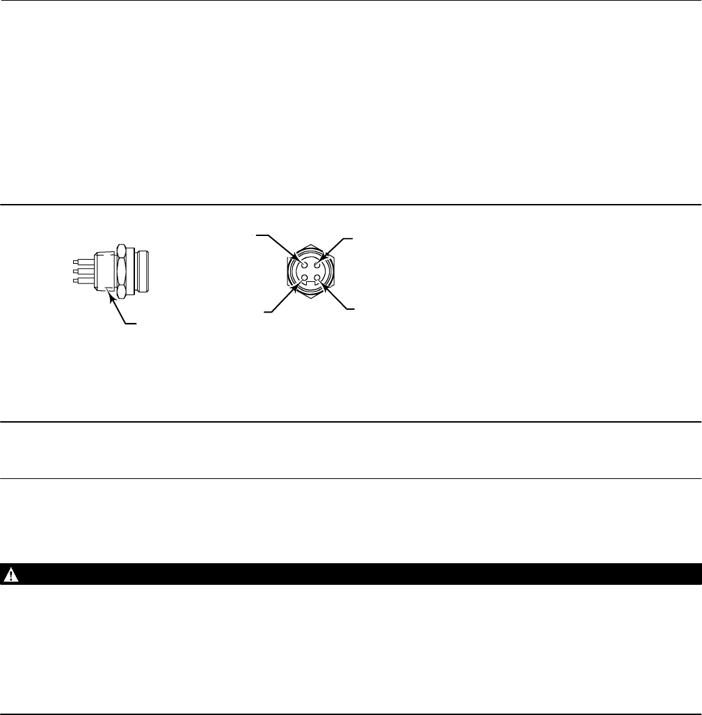
The DVC6200f is offered with a quick connect cable entry option, shown in figure 2‐1, for the FOUNDATION fieldbus
signal. The quick connect cable entry provides an easier and more reliable interface to fieldbus devices and support
modules by providing a standard connection.
Figure 2‐1. Quick Connect Connector
1/2‐14 NPT
1 (BLUE)
2 (BROWN)
3 (NC)
4 (GREEN/YELLOW)
NOTES:
1. COLORS ARE WIRE COLORS.
2. NC=NO CONNECTION.
18B9424‐A
Note
The quick connect cable entry option is only available for intrinsically safe and non‐incendive installations.
Refer to figure 8‐2 for identification of parts.
WARNING
Personal injury or property damage, caused by fire or explosion, can result from the discharge of static electricity. Connect
a 14 AWG (2.08 mm2) ground strap between the digital valve controller and earth ground when flammable or hazardous
gases are present. Refer to national and local codes and standards for grounding requirements.
To avoid static discharge from the plastic cover, do not rub or clean the cover with solvents. Clean with a mild detergent
and water only.
To avoid personal injury or property damage, do not use the Quick Connect option on instruments in explosion‐proof or
flameproof installations.
1. The quick connect cable entry should be installed on the digital valve controller at the factory. If it is, proceed to
step 3. If not continue with step 2.
2. To install the Quick Connect:
a. Remove the terminal box cap (key 4) from the terminal box (key 3).
b. Apply sealant to the threads of the quick connector.
c. Insert the wire pigtail into the desired conduit opening on the terminal box. Tighten the quick connector in the
conduit opening.
Instruction Manual
D103412X012
Installation Information
January 2015
12
d. Cut and trim the wire ends.
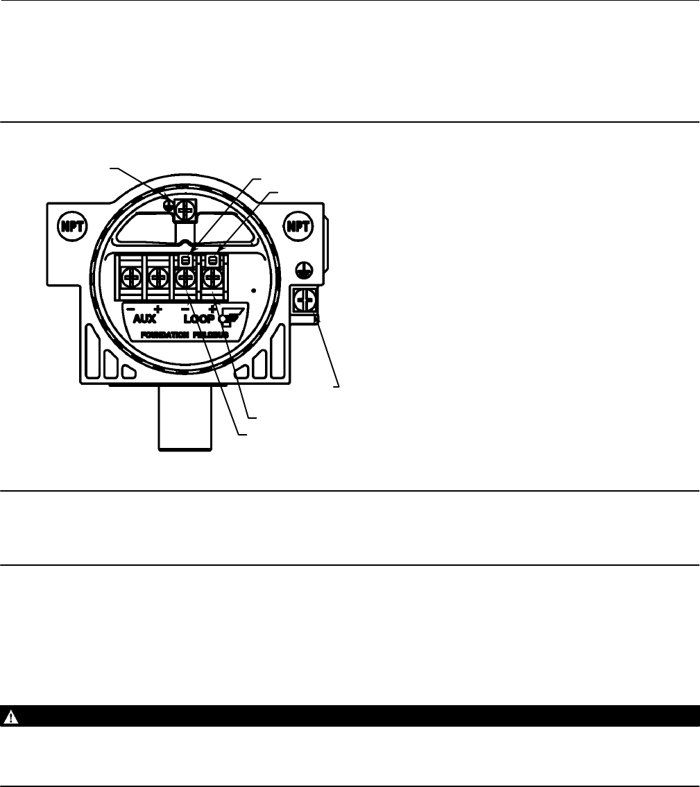
e. The instrument is not polarity sensitive. Refer to figure 2‐2. Connect the blue wire to one of the LOOP terminals
in the terminal box. Connect the brown wire to the other LOOP terminal. Cut the green/yellow wire off inside of
the DVC6200f, and ensure that the shield is totally isolated at the instrument end.
Figure 2‐2. Loop Connections Terminal Box
GE41456-A
SAFETY
GROUND
LOOP
LOOP
TALK
TALK
EARTH
GROUND
Note
The green/yellow wire is cut off inside the DVC6200f to help prevent ground loop issues. The only wires that should be installed
and left on the connector are the two signal wires.
f. Replace the terminal box cap on the terminal box. To secure the terminal box cap engage the lock screw.
3. Connect the field wiring connector to the installed quick connector.
Communication Connections
WARNING
Personal injury or property damage caused by fire or explosion may occur if this connection is attempted in a potentially
explosive atmosphere or in an area that has been classified as hazardous. Confirm that area classification and atmosphere
conditions permit the safe removal of the terminal box cap before proceeding.
A FOUNDATION fieldbus communicating device, such as a Field Communicator or a personal computer running
ValveLink software, interfaces with the DVC6200f digital valve controller from any wiring termination point in the
segment. If you choose to connect the fieldbus communicating device directly to the instrument, attach the device to
the LOCAL connections inside the terminal box to provide local communications with the instrument.

Instruction Manual
D103412X012
Installation Information
January 2015
13
Simulate Enable Jumper
WARNING
Personal injury or property damage caused by fire or explosion may occur if this connection is attempted in a potentially
explosive atmosphere or in an area that has been classified as hazardous. Confirm that area classification and atmosphere
conditions permit the safe removal of the terminal box cap before proceeding.
Install a jumper across the SIMULATE ENABLE terminals to enable the instrument to accept a simulate command.
(These terminals are marked AUX on the terminal board, see figure 2‐2). With the jumper in place and the simulate
parameter in the AO or DO block set to enabled, the transducer block ignores the output of the AO or DO block. The
simulate value and status become the readback value and status to the AO or DO block and the transducer block is
ignored. For more information on running simulations, see the Detailed Setup section of this manual, the FOUNDATION
fieldbus specifications, and the host documentation.
WARNING
Removing the jumper will disable the simulate, which may cause the valve to move. To avoid personal injury and property
damage caused by the release of pressure or process fluid, provide some temporary means of control for the process.

Instruction Manual
D103412X012
Installation Information
January 2015
14
Instruction Manual
D103412X012
Basic Setup
January 2015
15
Section 3 Basic Setup3-3-
Basic Setup
Field Communicator TB > Configure/Setup > Basic Setup
WARNING
Changes to the instrument setup may cause changes in the output pressure or valve travel. Depending on the application,
these changes may upset process control, which may result in personal injury or property damage.
When the DVC6200f digital valve controller is ordered as part of a control valve assembly, the factory mounts the
digital valve controller and sets up the instrument as specified on the order. When mounting to a valve in the field, the
instrument needs to be setup to match the instrument to the valve and actuator.
Before beginning basic setup, be sure the instrument is correctly mounted as described in the Installation section.
Basic Setup includes the following procedures:
Device Setup
Auto Travel Calibrate
Performance Tuner (Optional)
Note
The DVC6200f may keep the Transducer Block Mode Out‐of‐Service if the instrument is not properly mounted.
To setup and calibrate the instrument, the Transducer Block Mode must be Manual, and the Protection must be None.
When using DD methods the method will request that you change the mode, but make changes in Protection automatically. If you
have a host system that overrides transducer block parameters ensure that the Protection setting is not left as None. Doing so will
result in transducer block parameters being overwritten.
Transducer Block Mode
Field Communicator TB > Configure/Setup > Detailed Setup > Transducer Block Mode
To setup and calibrate the instrument, the transducer block mode must be in Manual. For more information about
transducer block mode, refer to page 38.
Protection
Field Communicator TB > Configure/Setup > Detailed Setup > Protection
To setup and calibrate the instrument, the protection must be set to None with the Field Communicator. For more
information about configuration protection refer to page 38.

Instruction Manual
D103412X012
Basic Setup
January 2015
16
Device Setup
Field Communicator TB > Configure/Setup > Basic Setup > Device Setup
Follow the prompts on the Field Communicator display to automatically setup the instrument using specified actuator
information. Table 3‐2 provides the actuator information required to setup and calibrate the instrument.
Note
If reverse‐acting relay B is used, you must manually set the Relay Type (BASIC_SETUP.RELAY_TYPE [42.5]) to B. This will not be set
during Device Setup.
1. Select whether Travel, Travel with Pressure fallback (auto recovery or manual recovery) or Pressure Control is
desired. Refer to page 42 for additional information.
2. Enter the pressure units: kPa, bar, psi, inHg, inH2O, or kg/cm2.
3. Enter the maximum instrument supply pressure and output pressure range (if required).
4. Enter the manufacturer of the actuator on which the instrument is mounted. If the actuator manufacturer is not
listed, select Other.
5. Enter the actuator model or type. If the actuator model is not listed, select Other.
6. Enter the actuator size.
7. Indicate whether a Volume Booster is being used.
8. Specify if factory defaults should be used for basic setup. If you select YES for factory default, the Field
Communicator sets the setup parameters to the values listed in table 3‐1. If you select NO for the factory defaults,
the setup parameters listed in the table remain at their previous settings.
Table 3‐1. Factory Default Settings
Setup Parameter Default Setting
Travel Cutoff Hi
Travel Cutoff Lo
Travel Integral Gain
Travel Calibration Trigger
99.5%
0.5%
9.4 repeats/min
No
Travel Integral Enable
Travel Integral Limit Hi
Travel Integral Limit Lo
Travel Integral Deadzone
On
30%
-30%
0.25%
Pressure Cutoff Hi
Pressure Cutoff Lo
Pressure Integral Deadzone
Pressure Integral Hi Limit
Pressure Integral Lo Limit
99.5%
-0.5%
0.25%
50.0%
-50.0%
Input Characterization
Shutdown Trigger
Shutdown Recovery
Output Block Timeout
Linear
All Off
All Auto Recovery
600 sec

Instruction Manual
D103412X012
Basic Setup
January 2015
17
Table 3‐2. Actuator Information for Initial Setup
Actuator
Manufacturer Actuator Model Actuator Size Actuator Style Starting
Tuning Set
Travel Sensor Motion(2)
Relay A or C(3)
Fisher
585C & 585CR
25
50
60
68, 80
100, 130
Piston Dbl w/ or w/o
Spring. See actuator
instruction manual and
nameplate.
E
I
J
L
M
User Specified
657
30
34, 40
45, 50
46, 60, 70, 76, &
80‐100
Spring & Diaphragm
H
K
L
M
Away from the top of the instrument
667
30
34, 40
45, 50
46, 60, 70, 76, &
80‐100
Spring & Diaphragm
H
K
L
M
Towards the top of the instrument
1051 & 1052
20, 30
33
40
60, 70
Spring & Diaphragm
(Window-mount)
H
I
K
M
Away from the top of the instrument
1061
30
40
60
68, 80, 100, 130
Piston Dbl w/o Spring
J
K
L
M
Depends upon pneumatic connections. See
description for Travel Sensor Motion
1066SR 20
27, 75 Piston Sgl w/Spring G
L
Mounting Style Travel Sensor Motion
AAway from the top of the
instrument
BTowards the top of the
instrument
CTowards the top of the
instrument
DAway from the top of the
instrument
2052
1
2
3
Spring & Diaphragm
(Window-mount)
H
K
M
Away from the top of the instrument
3024
30, 30E
34, 34E, 40, 40E
45, 45E
Spring & Diaphragm
E
H
K
For Po operating mode (air opens):
Towards the top of the instrument
For Ps operating mode (air closes):
Away from the top of the instrument
GX
225
Spring & Diaphragm
X(1) Air to Open
Towards the top
of the instrument
Air to Close
Away from the top of the
instrument
750 K
1200 M
Baumann
Air to Extend 16
32
54 Spring & Diaphragm
C
E
H
Towards the top of the instrument
Air to Retract Away from the top of the instrument
Rotary
10
25
54
E
H
J
Specify
NOTE: Refer to table 4‐10 for feedback connection (magnet assembly) information.
1. X = Expert Tuning. Proportional Gain = 4.2; Velocity Gain = 3.0; Minor Loop Feedback Gain = 18.0
2. Travel Sensor Motion in this instance refers to the motion of the magnet assembly.
3. Values shown are for Relay A and C. Reverse for Relay B.

Instruction Manual
D103412X012
Basic Setup
January 2015
18
Typically Device Setup determines the required setup information based upon the actuator manufacturer and model
specified. However, if you enter OTHER for the actuator manufacturer or the actuator model, then you will be
prompted for setup parameters such as:
Actuator Style—Select spring & diaphragm, piston double‐acting without spring, piston single‐acting with spring,
piston double‐acting with spring.
Valve Style—Select the valve style, rotary or sliding‐stem.
Zero Power Condition—this identifies whether the valve is fully open or fully closed when the input is 0%. If you are
unsure how to set this parameter, disconnect the instrument from the segment. (With double‐acting and
single‐acting direct digital valve controllers, disconnecting the instrument from the segment is the same as setting
the output A pressure to zero. For single‐acting reverse digital valve controllers, disconnecting the instrument from
the segment is the same as setting the output B pressure to supply.)
WARNING
If you answer YES to the prompt for permission to move the valve when setting the Travel Sensor Motion, the instrument
will move the valve through its full travel range. To avoid personal injury and property damage caused by the release of
pressure or process fluid, isolate the valve from the process and equalize pressure on both sides of the valve or bleed off the
process fluid.
Travel Sensor Motion—Device Setup asks if it can move the valve to determine travel sensor motion. If you answer
Yes, the instrument will stroke the valve the full travel span to determine travel sensor motion. If you answer No,
then you must specify the direction of travel movement. For quarter‐turn actuators determine rotation by viewing
the rotation of the magnet assembly from the back of the instrument.
Note
Travel Sensor Motion in this instance refers to the motion of the magnet assembly. Note that the magnet assembly may be
referred to as a magnetic array in user interface tools.
For instruments with relay A or C If increasing air pressure at output A causes the magnet assembly to move up, or
the actuator shaft to rotate counterclockwise, enter “Towards Top of Instrument/CCW.” If it causes the magnet
assembly to move down, or the actuator shaft to rotate clockwise, enter “Away From Top of Instrument/CW.” For
instruments with relay B.
For instruments with relay B If decreasing air pressure at output B causes the magnet assembly to move up, or the
actuator shaft to rotate counterclockwise, enter “Towards Top of Instrument/CCW.” If it causes the magnet
assembly to move down, or the actuator shaft to rotate clockwise, enter “Away From Top of Instrument/CW.”
Note
Relay A adjustment may be required before Device Setup can determine travel sensor motion. Follow the prompts on the Field
Communicator display if relay adjustment is necessary.
Table 3‐2 lists the required Travel Sensor Motion selections for Fisher and Baumann actuators.

Instruction Manual
D103412X012
Basic Setup
January 2015
19
Tuning Set—There are twelve tuning sets to choose from. Each tuning set provides a preselected value for the digital
valve controller gain settings. Tuning set C provides the slowest response and M provides the fastest response. For
smaller actuators use tuning set C or D. For larger actuators using tuning set F or G. Table 3‐3 lists the values for
preselected tuning sets.
Note
Tuning set B is only available in Pressure Control Mode.
Table 3‐3. Gain Values for Preselected Tuning Sets
Tuning Set
Travel Pressure
Proportional Gain Velocity Gain Minor Loop
Feedback Gain Proportional Gain Integrator Gain Minor Loop
Feedback Gain
B
C
D
E
F
G
‐ ‐ ‐
4.4
4.8
5.5
6.2
7.2
‐ ‐ ‐
3.0
3.0
3.0
3.1
3.6
‐ ‐ ‐
35
35
35
35
34
0.5
2.2
2.4
2.8
3.1
3.6
0.3
0.1
0.1
0.1
0.1
0.1
35
35
35
35
35
34
H
I
J
K
L
M
8.4
9.7
11.3
13.1
15.5
18.0
4.2
4.8
5.6
6.0
6.0
6.0
31
27
23
18
12
12
4.2
4.8
5.6
6.6
7.8
9.0
0.1
0.1
0.1
0.1
0.1
0.1
31
27
23
18
12
12
X (Expert) User Adjusted User Adjusted User Adjusted User Adjusted User Adjusted User Adjusted
WARNING
Changes to the tuning set may cause the valve/actuator assembly to stroke. To avoid personal injury or property damage
caused by moving parts, keep hands, tools, and other objects away from the valve/actuator assembly.
In addition, you can select Expert, which allows you to individually set the proportional gain, velocity gain, and minor
loop feedback gain for travel tuning and pressure proportional gain, pressure integrator gain, and pressure minor loop
feedback gain for pressure tuning. Refer to page 39 for additional information on travel tuning and page 41 for
pressure tuning.
Note
Use Expert tuning only if standard tuning has not achieved the desired results.
Stabilize/Optimize or Performance Tuner may be used to achieve the desired results more rapidly than expert tuning.
Table 3‐2 provides tuning set selection guidelines for Fisher and Baumann actuators. These tuning sets are only
recommended starting points. After you finish setting up and calibrating the instrument, use Stabilize/Optimize to
adjust the tuning set to get the desired response.

Instruction Manual
D103412X012
Basic Setup
January 2015
20
When Device Setup is complete you are asked if you wish to run Auto Calibration now. Select yes to automatically
calibrate instrument travel at this time. Follow the prompts on the Field Communicator display. The calibration
procedure uses the valve and actuator stops as the 0% and 100% calibration points. For additional information, refer to
Auto Calibration in the Calibration section.
Note
Single‐acting relay B and C are not user‐adjustable. However, it is recommended that you check the relay adjustment for
double‐acting relay A in new installations before proceeding with travel calibration.
Refer to page 191 for relay adjustment instructions.
If after completing setup and calibration the valve cycles or overshoots (unstable), or is unresponsive (sluggish), you
can improve operation by running Performance Tuner or Stabilize/Optimize.
Performance Tuner
Field Communicator TB > Configure/Setup > Basic Setup > Performance Tuner
WARNING
During performance tuning the valve may move, causing process fluid or pressure to be released. To avoid personal injury
and property damage caused by the release of process fluid or pressure, isolate the valve from the process and equalize
pressure on both sides of the valve or bleed off the process fluid.
The Performance Tuner is used to determine digital valve controller tuning. It will move the valve slightly and monitor
the effects of small tuning changes until an optimum control response is achieved. Because the Performance Tuner
can detect internal instabilities before they become apparent in the travel response, it can generally optimize tuning
more effectively than manual tuning. Typically, the Performance Tuner takes 3 to 5 minutes to tune an instrument,
although tuning instruments mounted on larger actuators may take longer.

Instruction Manual
D103412X012
Detailed Setup—Resource Block
January 2015
21
Section 4 Detailed Setup 4-4-
Resource Block
Overview
The resource block contains the hardware specific characteristics associated with a device; it has no input or output
parameters. The resource block monitors and controls the general operation of other blocks within the device. Most of
the resource block parameters are operational parameters that provide information about the instrument such as
identification, hardware information, available options, etc. and are read only. Configuration of the resource block
involves selecting features from those that are available, setting the mode, setting write lock, and setting up alert
reporting details.
The following procedures address only the key resource block parameters; however, all resource block parameters are
listed in table 4‐3.
Configure/Setup
Setup
Resource Block Mode
Field Communicator RB > Configure/Setup > Setup > Resource Block Mode
Modes
The resource block can be in one of two modes (MODE_BLK [5]):
Automatic (Auto)—This is the operational mode for this block. When the resource block is in the Auto mode, all
other function blocks are allowed to function normally.
Out of Service (OOS)—Placing the resource block in Out of Service mode stops all function block execution, by
setting their modes to Out of Service as well. The actual mode of the function blocks is changed to Out of Service, but
the function block target modes are retained. Placing the resource block in the Out of Service mode does not affect
the mode of the transducer block.
Write Lock
Field Communicator RB > Configure/Setup > Write Lock
Write Lock
Write Lock (WRITE_LOCK [34]) determines if writes are permissible to other device parameters. The Firmware Write
Lock feature must be selected to be able to use Write Lock (see Features). When Write Lock is set to Locked, no writes
are permitted to any parameters within the device except to set Write Lock to Not Locked. When locked, the device
functions normally, updating inputs and outputs and executing algorithms. When Write Lock is set to Not Locked, the
Write Alarm (WRITE_ALM [40]) alert is active.

Instruction Manual
D103412X012
Detailed Setup—Resource Block
January 2015
22
Write Priority
Write Priority (WRITE_PRI [39]) sets the priority for Write Alarm. The lowest priority is 0. The highest is 15.
Communication Time Out
Field Communicator RB > Configure/Setup > Communication Time Out
Shed Remote Cascade
Note
Typically this parameter does not need to be changed. The unit will be operational using the default values assigned by the factory.
Perform this procedure only if a remote computer is sending setpoints from your “advanced” control.
Default value for RCas Timeout is 20 seconds.
Shed Remote Cascade (SHED_RCAS [26]) determines how long function blocks in the DVC6200f should wait before
giving up on remote computer writes to RCas parameters. When the timeout is exceeded, the block sheds to the next
mode as defined by the block shed options. If Shed Remote Cascade is set to 0, the block will not shed from RCas.
Enter a positive value in the Shed Remote Cascade field. Time duration is in 1/32 milliseconds (640000 = 20 secs).
Shed Remote Out
Note
Typically this parameter does not need to be changed. The unit will be operational using the default values assigned by the factory.
Perform this procedure only if a remote computer is sending setpoints from your “advanced” control.
Default value for Shed Remote Out is 20 seconds.
Shed Remote Out (SHED_ROUT [27]) determine how long function blocks in the DVC6200f should wait before giving
up on computer writes to ROut parameters. When the timeout is exceeded, the block sheds to the next mode as
defined by the block shed options. If Shed Remote Out is set to 0, the block will not shed from ROut. Enter a positive
value in the Shed Remote Out field. Time duration is in 1/32 milliseconds (640000 = 20 secs).
Options
Field Communicator RB > Configure/Setup > Options
Diagnostic Options
Diagnostic Options (DIAG_OPTIONS [45]) shows the diagnostic options available in the instrument.
Function Block Options
Function Block Options (FB_OPTIONS [44]) shows which function blocks are available in the instrument.

Instruction Manual
D103412X012
Detailed Setup—Resource Block
January 2015
23
Miscellaneous Options
Miscellaneous Options (MISC_OPTIONS [46]) indicates which miscellaneous licensing options are enabled.
Features Available
Features Available (FEATURES [17]) indicates which Resource Block Options features are available.
Reports—Reports enables alert and event reporting. Reporting of specific alerts may be suppressed. See Alerts on
page 45.
Fault State—Fault state enables the ability of the output block to react to various abnormal conditions by
shedding mode. See parameter descriptions for Set Fault State (SET_FSTATE [29]) and Clear Fault State
(CLR_FSTATE [30]) in table 4‐3 and “Action on Fault Detection”.
Soft Write Lock—Soft Write lock permits using Write Lock (WRITE_LOCK [34]) to prevent any external change to
parameter values. Block connections and calculation results will proceed normally, but the configuration is locked.
Also see Write Lock, on page 21.
Multi‐bit Alarm (Bit‐Alarm) Support— Multi‐bit Alarm (Bit‐Alarm) Support permits the instrument to treat each
PlantWeb alert separately when broadcast to the Host. Without Multi‐Bit Alarm Support, an individual PlantWeb
alert must be acknowledged before another PlantWeb alert can be broadcast to the Host
Features Selected
Note
Typically this parameter does not need to be changed. The unit will be operational using the default values assigned by the factory.
Fault State, Software Write Lock, and Output Readback are set by default.
Features Selected (FEATURE_SEL [18]) indicates which Resource Block Options features have been selected and is used
to select the desired features.
Reports—Selecting reports enables alert and event reporting. Reporting of specific alerts may be suppressed. See
Alerts on page 45.
Fault State—Selecting fault state enables the ability of the output block to react to various abnormal conditions by
shedding mode. See parameter descriptions for Set Fault State (SET_FSTATE [29]) and Clear Fault State
(CLR_FSTATE [30]) in table 4‐3 and “Action on Fault Detection”.
Soft Write Lock—When selected, permits using Write Lock (WRITE_LOCK [34]) to prevent any external change to
parameter values. Block connections and calculation results will proceed normally, but the configuration is locked.
Also see Write Lock, on page 21.
Multi‐bit Alarm (Bit‐Alarm) Support— When selected, the instrument will allow the instrument to treat each
PlantWeb alert separately when broadcast to the Host.
Alarm Handling
Field Communicator RB > Configure/Setup > Alarm Handling
Alert Key—Alert Key (ALERT_KEY [4]) is a number that permits grouping alerts. This number may be used to indicate
to the operator the source of the alert, such as the instrument, plant unit, etc. Enter a value between 1 and 255.

Instruction Manual
D103412X012
Detailed Setup—Resource Block
January 2015
24
Confirm Time—Confirm Time (CONFIRM_TIME [33]) determines the time, in 1/32 of a millisecond, the instrument
waits for confirmation of receipt of a report before trying again. If Confirm Time is 0, the instrument does not retry
to send the report. Enter 0 or a value between 320000 (10 secs) and 640000 (20 secs).
Limit Notify—Limit Notify (LIM_NOTIFY [32]) is the number of alert reports that the device can send without getting
a confirmation up to the maximum permitted in Maximum Notify (MAX_NOTIFY [31]). If Limit Notify is set to zero,
no alerts are reported. Enter a value between 0 and 3.
To have the instrument report alerts without having the host poll the alerts parameters, select the Reports feature
(see Feature Select).
Maximum Notify—Maximum Notify (MAX_NOTIFY [31]) indicates the maximum number of alert reports that the
device can send without getting a confirmation. This limit is determined by the amount of memory available for
alert messages. The number can be set lower, to control alert flooding, by adjusting Maximum Alerts Allowed
(LIM_NOTIFY [32]).
Block Alarm Disabled—The Block Alarm (BLOCK_ALM [36]) is used for all configuration, hardware, connection failure
or system problems in the block. Alarm Summary (ALARM_SUM [37]) determines if the Write Alarm (WRITE_ALM
[40]) and Block Alarm [BLOCK_ALM [36]) are disabled.
Block Alarm Auto Acknowledge—Acknowledge Option (ACK_OPTION [38]) determines if the block alarm will be
automatically acknowledged.
Discrete Alarm Disabled—The Write Alarm (WRITE_ALM [40]) is used to alert when parameters are writeable to the
device. Alarm Summary (ALARM_SUM [37]) determines if the Discrete Alarm is disabled.
Discrete Alarm Auto Acknowledge—Acknowledge Option (ACK_OPTION [38]) determines if the Write Alarm
associated with the block will be automatically acknowledged.
Identification
Field Communicator RB > Configure/Setup > Identification
Device ID—The 32 character Device ID (DEVICE_ID [54]).
Electronics Serial Number—The Electronics Serial Number (ELECTRONICS_SN [49]) set at the factory.
Factory Serial Number—The Factory Serial Number (FACTORY_SN [50]) is the instrument serial number set at the
factory.
Field Serial Number——The Field Serial Number (FIELD_SN [51]) is the serial number of instrument assigned in field.
Tag Description—The Tag Description (TAG_DESC [2]) is used to assign a unique 32 character description to each
block within the digital valve controller to describe the intended application for the block.
Strategy—Strategy (STRATEGY [3]) permits strategic grouping of blocks so the operator can identify where the
block is located. The blocks may be grouped by plant area, plant equipment, etc. Enter a value between 0 and
65535 in the Strategy field.
Manufacturer—Manufacturer Identification (MANUFAC_ID [10]) identifies the manufacturer of the instrument. It is
used by the host system to locate the DD file for the device. For Fisher the Manufacturer ID is 0x5100.
Device Type—Device Type (DEV_TYPE [11]) identifies the type of device. It is used by the host system to locate the
DD file for the device. For a DVC6200f digital valve controller the device type is 0x4602.

Instruction Manual
D103412X012
Detailed Setup—Resource Block
January 2015
25
Diagnostic Options—Diagnostic Options (DIAG_OPTIONS [45]) shows the diagnostic options available in the
instrument.
Version
Field Communicator RB > Configure/Setup > Version
Device Revision—The Device Revision (DEV_REV [12]) is the manufacturer's revision number associated with the
resource, used by an interface device to locate the DD file for the resource.
Firmware Revision—Firmware Revision (FIRMWARE_REVISION [47]) identifies the revision of the firmware that is
currently in use.
Standby Firmware Revision—Standby Firmware Revision (STBY_FIRMWARE_REVISION [55]) identifies the revision of
the alternative firmware.
Hardware Revision—Hardware Revision (HARDWARE_REV [48]) identifies the revision of the electronic hardware.
ITK Version—ITK Version (ITK_VER [41]) identifies the major version of the Interoperability Tester used by the
Fieldbus Foundation in certifying the device as interoperable. This device revision meets the requirements of
version 5.
Block Errors
Table 4‐1 lists conditions reported in the BLOCK_ERR [6] parameter. Conditions in italics are not applicable for the
Resource block and are provided only for your reference.
Table 4‐1. Resource Block BLOCK_ERR Conditions
Condition Number Condition Name and Description
0Other ‐ Set if a device initialization error occurred.
1Block Configuration Error ‐ Set if FEATURE_SEL, CYCLE_SEL, or CYCLE_TYPE is set incorrectly.
2Link Configuration Error ‐ N/A
3Simulate Active ‐ Indicates that the simulation jumper is in place on the aux terminals. This is not an indication that the I/O
blocks are using simulation data. See AO block parameter SIMULATE [10] and DO block parameter SIMULATE_D [10].
4Local Override ‐ N/A
5Device Fault State ‐ Indicates the device is in Fault State.
6Device Needs Maintenance Soon ‐ Indicates a Maintenance or Advisory PlantWeb Alert condition is active.
7Input failure/process variable had Bad status ‐ N/A
8Output failure ‐ N/A
9Memory failure ‐ Indicates a pending Flash or NVM failure.
10 Lost Static Data ‐ Indicates failure of the memory containing static parameters.
11 Lost NV Data ‐ Indicates failure of the memory containing non‐volatile parameters.
12 Readback Check Failed ‐ NA
13 Device Needs Maintenance Now ‐ Indicates a Failed PlantWeb Alert condition is active.
14 Power Up ‐ Indicates the device has been powered up and the Resource Block is not running normally.
15 Out of Service (MSB) ‐ The resource block actual mode is Out of Service.

Instruction Manual
D103412X012
Detailed Setup—Resource Block
January 2015
26
Table 4‐2. Parameters Affected by Restart with
Defaults
Index
Number Parameter Name Initial Value
Resource Block
1
2
3
4
ST_REV
TAG_DESC
STRATEGY
ALERT_KEY
0
spaces
0
0
5 MODE_BLK
TARGET
PERMITTED
NORMAL
Auto
Auto or Out of Service
Auto
14
18
20
GRANT_DENY
FEATURE_SEL
CYCLE_SEL
All bits: 0
Set by mfgr.
0:0
26
27
28
SHED_RCAS
SHED_ROUT
FAULT_STATE
640000
640000
1=Clear
32
33
34
37
LIM_NOTIFY
CONFIRM_TIME
WRITE_LOCK
ALARM_SUM
DISABLED
MAX_NOTIFY
640000
1=Unlocked
All bits: 0
38
39
ACK_OPTION
WRITE_PRI
Disabled
0
AO Block
1
2
3
4
ST_REV
TAG_DESC
STRATEGY
ALERT_KEY
0
spaces
0
0
5
8
9
MODE_BLK
TARGET
PERMITTED
NORMAL
SP
OUT
Out of Service
OOS+MAN+AUTO+CAS+RCAS
Auto
Dynamic
Dynamic
11 PV_SCALE
EU 100%
EU 0%
Engineering Units
Decimal Places
100
0
%
2
12
14
15
XD_SCALE
EU 100%
EU 0%
Engineering Units
Decimal Places
IO_OPTS
STATUS_OPTS
100
0
%
2
All off
All off
17
18
19
20
21
22
CAS_IN
SP_RATE_DN
SP_RATE_UP
SP_HI_LIM
SP_LO_LIM
CHANNEL
BAD:
NC:
const
0
+INF
+INF
100
0
1=analog valve input
-Continued-
Table 4‐2. Parameters Affected by Restart with
Defaults (Continued)
Index
Number Parameter Name Initial Value
AO Block (continued)
23
24
26
27
FSTATE_TIME
FSTATE_VAL
RCAS_IN
Status
Value
SHED_OPT
0
0
BAD:
NoComm:
NoVal:
const
0 Trk
All off
PID Block Parameters
1
2
3
4
ST_REV
TAG_DESC
STRATEGY
ALERT_KEY
0
spaces
0
0
5
8
9
MODE_BLK
TARGET
PERMITTED
NORMAL
SP
OUT
Out of Service
OOS+MAN+AUTO+CAS+
RCAS+ROUT
Auto
Dynamic
Dynamic
10 PV_SCALE
EU 100%
EU 0%
Engineering Units
Decimal Places
100
0
%
2
11
13
14
OUT_SCALE
EU 100%
EU 0%
Engineering Units
Decimal Places
CONTROL_OPTS
STATUS_OPTS
100
0
%
2
0: Bypass enable
All off
15
16
IN
Status
Value
PV_FTIME
BAD:
NC:
const
0
0
17
18
19
20
21
BYPASS
CAS_IN
Status
Value
SP_RATE_DN
SP_RATE_UP
SP_HI_LIM
0
BAD:
NC:
const
0
+INF
+INF
100
22
23
24
25
26
27
SP_LO_LIM
GAIN
RESET
BAL_TIME
RATE
BKCAL_IN
Status
Value
0
1
+INF
0
0
BAD:
NC:
const
0
-Continued-

Instruction Manual
D103412X012
Detailed Setup—Resource Block
January 2015
27
Table 4‐2. Parameters Affected by Restart with
Defaults (Continued)
Index
Number Parameter Name Initial Value
PID Block (continued)
28
29
30
32
33
OUT_HI_LIM
OUT_LO_LIM
BKCAL_HYS
RCAS_IN
Status
Value
ROUT_IN
Status
Value
100
0
0.5%
BAD:
NoCom:
NoVal:
const
0 Trk
BAD:
NoCom:
NoVal:
const
0 Trk
34
37
SHED_OPT
TRK_SCALE
EU 100%
EU 0%
Engineering Units
Decimal places
0
100
0
%
2
38
39
40
TRK_IN_D
Status
Value
TRK_VAL
Status
Value
FF_VAL
Status
Value
BAD:
NC:
const
0
BAD:
NC:
const
0
BAD:
NC:
const
0
41
42
45
46
FF_SCALE
EU 100%
EU 0%
Engineering Units
Decimal Places
FF_GAIN
ALARM_SUM
DISABLED
ACK_OPTION
100
0
%
2
0
0
Disabled
47
48
49
50
51
ALARM_HYS
HI_HI_PRI
HI_HI_LIM
HI_PRI
HI_LIM
0.5%
0
+INF
0
+INF
52
53
54
55
LO_PRI
LO_LIM
LO_LO_PRI
LO_LO_LIM
0
-INF
0
-INF
56
57
58
59
DV_HI_PRI
DV_HI_LIM
DV_LO_PRI
DV_LO_LIM
0
+INF
0
-INF
-Continued-
Table 4‐2. Parameters Affected by Restart with
Defaults (Continued)
Index
Number Parameter Name Initial Value
PID Block (continued)
66
69
70
71
72
73
74
BIAS
SP_FTIME
MATHFORM
STRUCTURECONFIG
GAMMA
BETA
IDEABAND
0
0
0
0
ISEL Block
1
2
3
4
ST_REV
TAG_DESC
STRATEGY
ALERT_KEY
0
spaces
0
0
5
7
MODE_BLK
TARGET
PERMITTED
NORMAL
OUT
Out of Service
OOS+MAN+AUTO
Auto
8 OUT_RANGE
EU 100%
EU 0%
Engineering Units
Decimal Places
100
0
%
2
10
11
12
STATUS_OPTS
IN_1
Status
Value
IN_2
Status
Value
All off
BAD
NC
cons
0
BAD
NC
cons
0
13
14
IN_3
Status
Value
IN_4
Status
Value
BAD
NC
cons
0
BAD
NC
cons
0
15
16
DISABLE_1
Status
Value
DISABLE_2
Status
Value
BAD
NC
cons
0
BAD
NC
cons
0
-Continued-

Instruction Manual
D103412X012
Detailed Setup—Resource Block
January 2015
28
Table 4‐2. Parameters Affected by Restart with
Defaults (Continued)
Index
Number Parameter Name Initial Value
ISEL Block (continued)
17
18
DISABLE_3
Status
Value
DISABLE_4
Status
Value
BAD
NC
cons
0
BAD
NC
cons
0
19
20
22
SELECT_TYPE
MIN_GOOD
OP_SELECT
Status
Value
All off
0
BAD
NC
constant
0
25
26
IN_5
Status
Value
IN_6
Status
Value
BAD
NC
cons
0
BAD
NC
cons
0
27
28
IN_7
Status
Value
IN_8
Status
Value
BAD
NC
cons
0
BAD
NC
cons
0
29
30
DISABLE_5
Status
Value
DISABLE_6
Status
Value
BAD
NC
cons
0
BAD
NC
cons
0
31
32
DISABLE_7
Status
Value
DISABLE_8
Status
Value
BAD
NC
cons
0
BAD
NC
cons
0
33
34
35
36
37
AVG_USE
ALARM_SUM
DISABLED
ACK_OPTION
ALARM_HYS
HI_HI_PRI
0
0
0
0.5%
0
-Continued-
Table 4‐2. Parameters Affected by Restart with
Defaults (Continued)
Index
Number Parameter Name Initial Value
ISEL Block (continued)
38
39
40
41
42
43
HI_HI_LIM
HI_PRI
HI_LIM
LO_PRI
LO_LIM
LO_LO_PRI
0
0
0
0
0
0
44
49
50
LO_LO_LIM
OUT_D
ALM_SEL
0
All bits: 0
DI Block
1
2
3
4
ST_REV
TAG_DESC
STRATEGY
ALERT_KEY
0
spaces
0
0
5
8
10
11
13
14
MODE_BLK
TARGET
PERMITTED
NORMAL
OUT_D
XD_STATE
OUT_STATE
IO_OPTS
STATUS_OPTS
Out of Service
OOS+MAN+AUTO
Auto
0
0
All off
All off
15
16
20
21
22
23
CHANNEL
PV_FTIME
ALARM_SUM
DISABLED
ACK_OPTION
DISC_PRI
DISC_LIM
0
0
0
All off
0
0
OS Block
1
2
3
4
ST_REV
TAG_DESC
STRATEGY
ALERT_KEY
0
spaces
0
0
5
7
8
9
10
MODE_BLK
TARGET
PERMITTED
NORMAL
SP
OUT_1
OUT_2
OUT_1_RANGE
EU 100%
EU 0%
Engineering Units
Decimal Places
Out of Service
OOS+MAN+AUTO
AUTO+CAS
100
0
%
2
11 OUT_2_RANGE
EU 100%
EU 0%
Engineering Units
Decimal Places
100
0
%
2
13
14
STATUS_OPTS
CAS_IN
Status
Value
disabled
BAD
NC
const
0
-Continued-

Instruction Manual
D103412X012
Detailed Setup—Resource Block
January 2015
29
Table 4‐2. Table Parameters Affected by Restart with
Defaults (Continued)
Index
Number Parameter Name Initial Value
OS Block (continued)
19 BKCAL_1_IN
Status
Value
BAD
NC
const
0
20
21
BKCAL_2_IN
Status
Value
BAL_TIME
BAD
NC
const
0
0
AI Block
1
2
3
4
ST_REV
TAG_DESC
STRATEGY
ALERT_KEY
0
spaces
0
0
5
8
10
MODE_BLK
TARGET
PERMITTED
NORMAL
OUT
XD_SCALE
EU at 100%
EU 0%
Units Index
Decimal point
Out of Service
OOS, MAN, AUTO
Auto
100
0
%
2
11
13
14
15
16
OUT_SCALE
EU 100%
EU 0%
Units Index
Decimal point
I/O OPTS
STATUS OPTS
CHANNEL
L_TYPE
100
0
Trk s/b%
2
disabled
disabled
0
0
17
18
22
23
24
LOW_CUT
PV_FTIME
ALARM_SUM
DISABLED
ACK_OPTION
ALARM_HYS
0
0
0
Disabled
0.5%
25
26
27
28
HI_HI_PRI
HI_HI_LIM
HI_PRI
HI_LIM
0
0
0
0
29
30
31
32
37
38
LO_PRI
LO_LIM
LO_LO_PRI
LO_LO_LIM
OUT_D
ALM_SEL
0
0
0
0
unselected
MAI Block
1
2
3
4
ST_REV
TAG_DESC
STRATEGY
ALERT_KEY
0
spaces
0
0
-Continued-
Table 4‐2. Parameters Affected by Restart with
Defaults (Continued)
Index
Number Parameter Name Initial Value
MAI Block (continued)
5
7
8
9
10
11
12
13
14
15
MODE_BLK
TARGET
PERMITTED
NORMAL
CHANNEL
OUT_1
OUT_2
OUT_3
OUT_4
OUT_5
OUT_6
OUT_7
OUT_8
Out of Service
OOS, MAN, AUTO
Auto
TB.FINAL_VALUE
TB.TRAVEL_TARGET
TB.FINAL_POSITION_VALUE
TB.TRAVEL
TB.SUPPLY_PRESS
TB.ACT_PRESS_A
TB.ACT_PRESS_B
TB.ACT_PRESS_DIFF
DO Block
1
2
3
4
ST_REV
TAG_DESC
STRATEGY
ALERT_KEY
0
spaces
0
0
5
8
9
MODE_BLK
TARGET
PERMITTED
NORMAL
SP_D
OUT_D
Out of Service
OOS+MAN+AUTO+CAS+
RCAS
AUTO+CAS
11
12
14
15
PV_STATE
XD_STATE
IO_OPTS
STATUS_OPTS
0
0
All off
All off
17
18
19
CAS_IN_D
Status
Value
CHANNEL
FSTATE_TIME
BAD
NC
const
0
22
0
20
22
23
27
28
FSTATE_VAL_D
RCAS_IN_D
Status
Value
SHED_OPT
SP_RATE_UP
SP_RATE_DN
0
BAD
NoComm
NoVal
const
0
All off
0
0
Transducer Block
1
2
3
4
5
87
ST_REV
TAG_DESC
STRATEGY
ALERT_KEY
MODE_BLK
TARGET
PERMITTED
NORMAL
PROTECTION
N/A
NULL
0
1
Out of Service
AUTO, MAN, OOS
Auto
None

Instruction Manual
D103412X012
Detailed Setup—Resource Block
January 2015
30
Resource Block Parameter List
Read/Write Capability: RO - Read Only, RW - Read Write
Mode: The block mode(s) required to write to the parameter
Double indentation and shaded Index Number indicates sub‐parameter.
Table 4‐3. Resource Block Parameter Definitions
Label
PARAMETER_NAME
Index
Number
RO /
RW Mode Range Initial
Value Description
Static Revision
ST_REV 1 RO NA 0 to 65535 0
Data Type: Unsigned16
The revision level of the static data. Increments
by one each time a static parameter changes.
The value is reset to 0 whenever a Restart with
Defaults is performed. See Restarting the
Instrument.
Tag Description
TAG_DESC 2 RW NA 7 bit ASCII Spaces
Data Type: Octet String
The user description of the intended application
of the block. Null characters are not allowed in
this data type.
Strategy
STRATEGY 3 RW ALL 0 to 65535 0
Data Type: Unsigned16
Used to identify groupings of blocks. The data is
not checked or processed by the block.
Alert Key
ALERT_KEY 4 RW ALL 1 to 255 0
Data Type: Unsigned8
The identification number of the plant unit.
Devices in a loop or plant section can be
assigned with a common alert key to aid the
operator in determining location of alerts.
Block Mode
MODE_BLK 5
TARGET_MODE 5.1 RW ALL 3: Auto
7: OOS 3: Auto
Data Type: DS‐69
The actual, target, permitted, and normal
modes.
Target: The requested block mode
Actual: The current mode of the block
Permitted: Allowed modes for Target
Normal: Most common mode for Target
ACTUAL_MODE 5.2 RO NA
3: Auto
6: IMAN (only during
initialization
7: OOS
N/A
PERMITTED_MODE 5.3 RW ALL 3: Auto
7: OOS
3: Auto
7: OOS
NORMAL_MODE 5.4 RW ALL 3: Auto 3: Auto
Block Error
BLOCK_ERR 6 RO N/A
0: Other
1: Block Configuration
Error
3: Simulate Active
6: Device needs
Maintenance Soon
9: Memory Failure
10: Lost Static Data
11: Lost Non‐Volatile
Memory
13: Device needs
Maintenance Now
14: Power‐up
15: Out‐of‐
Service (MSB)
Dynamic
Data Type: Bit String
0 = Inactive
1 = Active
Error status associated with hardware or
software for the resource block. When an error is
shown it may be broadcast to the host through
BLOCK_ALM.
Device State
RS_STATE 7 RO N/A
2: Initialization,
Actual mode=IMAN
4: On‐line, Actual
Mode=Auto
5: Standby, Actual
Mode=OOS
6: Failure, Actual
Mode=OOS
5: Standby
Data Type: Unsigned8
State of the function block application state
machine.
Test Read Write
TEST_RW 8 ALL 0
This parameter may be used in interoperability
testing to read and write all standard data types
supported by the Fieldbus Foundation.
-Continued-

Instruction Manual
D103412X012
Detailed Setup—Resource Block
January 2015
31
Table 4‐3. Resource Block Parameter Definitions (Continued)
Description
Initial
Value
RangeMode
RO /
RW
Index
Number
Label
PARAMETER_NAME
DD Resource
DD_RESOURCE 9 RO N/A Spaces
Data Type: Visible String
String identifying the VFD tag of the resource
that contains the Device Description for this
resource.
Manufacturer Id
MANUFAC_ID 10 RO N/A 0x5100
Data Type: Unsigned32
Manufacturer identification number, used by an
interface device or host to locate the DD file for
the resource. All manufacturer identification
numbers are maintained by the Fieldbus
Foundation. A host usually will have a base
directory for DD files. In this directory is a
subdirectory for each manufacturer id. In each
manufacturer id subdirectory is a directory for
each device type made by that manufacturer.
The device type directories contain files named
by combining the device revision for the
particular device type with the revision of the
device description. The manufacturer id for
Fisher is 0x005100.
Device Type
DEV_TYPE 11 RO N/A 4602
Data Type: Unsigned16
Manufacturer's model number associated with
the resource, used by an interface device to
locate the DD file for the resource.
Device Revision
DEV_REV 12 RO N/A Varies with
release
Data Type: Unsigned8
Manufacturer's revision number associated with
the resource, used by an interface device to
locate the DD file for the resource.
DD Revision
DD_REV 13 RO N/A Varies with
release
Data Type: Unsigned8
The minimum revision of the device description
(DD) than can be used with the device revision
of the instrument. Used by the interface device
to prevent the use of DDs that are incompatible
with the firmware in the instrument.
Grant Deny
GRANT_DENY 14
GRANT 14.1 RW ALL Valid Bits:
0: Program
1: Tune
2: Alarm
3: Local
All bits: 0
Data Type: DS‐70
Options for controlling access of a host
computer and to block parameters. Parameter
contains two attributes Grant and Deny each
with program, tune, alarm and local
permissions. Clearing a grant permission sets
the corresponding deny permission, 0 = N/A, 1 =
granted.
Deny permissions may be cleared through the
Deny attribute but not set, 0 = N/A, 1 = denied.
DENY 14.2 RW ALL All bits: 0
Hard Types
HARD_TYPES 15 RO N/A
0: Scalar Input
1: Scalar Output
2: Discrete Input
3: Discrete Output
0: 1
1: 1
2: 1
3: 1
Data Type: Bit String
0 = Inactive
1 = Active
The types of hardware available as channel
numbers in this resource.
Restart
RESTART 16 RW ALL
1=Run
2=Restart resource
3=Restart with
defaults
4=Restart processor
1=Run
Data Type: Unsigned8
Allows a manual restart to be initiated. For
details see Restarting the Instrument in this
section.
Features
FEATURES 17 RO ALL
1: Reports supported
2: Fault State
supported
3: Software Write
lock supported
10: Reannunciation
supported
1: 1
2: 1
3: 1
10: 1
Data Type: Bit String
0 = Inactive
1 = Active
Shows the supported resource block options.
Options are turned on and off via
FEATURE_SELECT.
-Continued-

Instruction Manual
D103412X012
Detailed Setup—Resource Block
January 2015
32
Table 4‐3. Resource Block Parameter Definitions (Continued)
Description
Initial
Value
RangeMode
RO /
RW
Index
Number
Label
PARAMETER_NAME
Features Selected
FEATURE_SEL 18 RW ALL
1: Reports Supported
2: Fault State
supported
3: Software Write lock
supported
10:Reannunciation
supported
1:0
2:1
3:1
10:0
Data Type: Bit String
0 = Inactive
1 = Active
Shows the selected resource block options. For
details see Device Features in this section.
Cycle Type
CYCLE_TYPE 19 RO NA 0: Scheduled 0: 1
Data Type: Bit String
0 = Inactive
1 = Active
Identifies the block execution methods available
for this resource, may be scheduled, completion
of block execution
Cycle Selection
CYCLE_SEL 20 ALL 0: Scheduled 0: 0
Data Type: Bit String
0 = Inactive
1 = Active
Identifies the block execution method selected
for this resource.
Minimum Cycle Time
MIN_CYCLE_T 21 RO NA 3200 3200
Data Type: Unsigned32
Time duration of the shortest cycle interval (in
1/32 millisecond) of which the resource is
capable. In the digital valve controller this value
is fixed at 3200 (100 milliseconds).
Memory Size
MEMORY_SIZE 22 RO NA 45 45
Date Type: Unsigned16
Memory, in kilobytes, available for additional
function blocks. Because no additional function
blocks may be added to DVC6200f instruments,
this parameter value is fixed at 45.
Nonvolatile Cycle Time
NV_CYCLE_T 23 RO NA Positive 576,000
Date Type: Unsigned32
This parameter identifies the minimum time
interval (in 1/32 milliseconds) between copies of
NV class data to NV memory. NV memory is
updated only if there has been a change in the
dynamic value. The last value saved in NV
memory will be available for the restart
procedure or a power cycle. A non‐zero value
regulates the frequency of writes, thus
protecting the life span of the device. If the value
is zero, data will never be automatically copied.
Changes made by other than publishing to NV
parameters will be copied to non‐volatile
memory immediately. For DVC6200f
instruments, this parameter value is fixed at
576,000 (18 seconds).
Free Space
FREE_SPACE 24 RO NA 0 to 100% 0
Data Type: Float
Percent of memory available for additional
function blocks (see also MEMORY_SIZE).
Because no additional function blocks may be
added to DVC6200f instruments, this parameter
value is fixed at 0.
Free Time
FREE_TIME 25 RO NA 0 to 100% 0
Data Type: Float
Percent of block processing time that is free to
process additional blocks. Because no additional
function blocks may be added to DVC6200f
instruments, this parameter value is fixed at 0.
RCAS Timeout
SHED_RCAS 26 RW ALL Positive 640000
Date Type: Unsigned32
Time duration (in 1/32 millisecond) at which to
give up on computer writes to function block
RCAS parameters. If this time is exceeded then
the function block will change to a mode other
than RCAS based on the SHED_OPT parameter
setting. Shed from RCAS mode never happens
when SHED_RCAS is set to zero.
-Continued-

Instruction Manual
D103412X012
Detailed Setup—Resource Block
January 2015
33
Table 4‐3. Resource Block Parameter Definitions (Continued)
Description
Initial
Value
RangeMode
RO /
RW
Index
Number
Label
PARAMETER_NAME
ROUT Timeout
SHED_ROUT 27 RW ALL Positive 640000
Data Type: Unsigned32
Time duration (in 1/32 millisecond) at which to
give up on computer writes to function block
ROUT parameters. If this time is exceeded then
the function block will change to a mode other
than ROUT based on the SHED_OPT parameter
setting. Shed from ROUT mode never happens
when SHED_ROUT is set to zero.
Fault State
FAULT_STATE 28 RO N/A 1=Clear
2=Active 1=Clear
Data Type: Unsigned8
Forces output function blocks that are not Out
of Service to the fault state condition. While this
parameter is active the output function blocks
will go to an actual mode of Local Override (LO)
and will perform their fault state actions (see
Action On Fault Detection for the output blocks
on pages 94 and 170 of this section). This
parameter is used to test the fault state behavior
that normally occurs when there is a
communication problem between devices. This
parameter is changed by the SET_FSTATE and
CLR_FSTATE parameters so long as the feature
Fault State is selected (see Feature Selection
[index number 18] in this table).
Set Fault State
SET_FSTATE 29 RW ALL 1=Off
2=Set 1=Off
Data Type: Unsigned8
Selecting Set changes the parameter
FAULT_STATE to Active. This is essentially a
“write only” parameter as it will always read OFF
because it is defined as momentary. Writing a
value of OFF has no affect. To use this parameter
the feature Fault State must be selected (see
Features Selected on page 23).
Clear Fault State
CLR_FSTATE 30 RW ALL 1=Off
2= Clear 1=Off
Data Type: Unsigned8
Selecting Clear changes the parameter
FAULT_STATE to Clear and clears the output
function blocks of the FAULT_STATE if the field
condition, if any, has cleared. This is essentially a
“write only” parameter as it will always read OFF
because it is defined as momentary. Writing a
value of OFF has no affect. To use this parameter
the feature Fault State must be selected (see
Features Selected on page 23.
Maximum Notify
MAX_NOTIFY 31 RO N/A 3 3
Data Type: Unsigned8
The maximum number of alert reports that this
device can send without getting a confirmation.
To control alert flooding, the number can be set
lower by adjusting the LIM_NOTIFY parameter
value. For DVC6200f instruments, this value is
fixed at 3.
Maximum Alerts Allow
LIM_NOTIFY 32 RW ALL 0 to MAX_NOTIFY MAX_NOTIFY
Data Type: Unsigned8
The number of alert reports that this device can
send without getting a confirmation up to the
maximum permitted in the parameter
MAX_NOTIFY. If set to zero, then no alerts are
reported.
Confirm Time
CONFIRM_TIME 33 RW ALL > 0
Set by FCS 640000
Data Type: Unsigned32
The time (in 1/32 millisecond) the device waits
for confirmation of receipt of an alert report
before trying again.
-Continued-

Instruction Manual
D103412X012
Detailed Setup—Resource Block
January 2015
34
Table 4‐3. Resource Block Parameter Definitions (Continued)
Description
Initial
Value
RangeMode
RO /
RW
Index
Number
Label
PARAMETER_NAME
Write Lock
WRITE_LOCK 34 RW ALL
0=Undefined
1=Unlocked
2=Locked
1=Unlocked
Data Type: Unsigned8
If set to Locked, no writes from anywhere are
allowed except to clear WRITE_LOCK by entering
Unlocked. Block inputs will continue to be
updated if they are subscribers. The feature Soft
Write Lock must be selected to enable writing to
this parameter (see Device Features in this
section).
Update Event
UPDATE_EVT 35
UNACKNOWLEDGED 35.1 RW ALL
0=Undefined
1=Acknowledged
2=Unacknowledged
0=Undefined
Data Type: DS‐73
This alert is generated by any change to the
static data. To support tracking changes in static
parameter values, the blocks static revision
parameter will be incremented each time a
static parameter value is changed. Also, the
blocks static revision parameter may be
incremented if a static parameter is written but
the value is not changed. If the Actual Mode is
not Out of Service and Reports is selected in the
Feature Select parameter, then this parameter
will be sent to the host system providing the
host has set up alert communications. Changes
to static data while the block is Out of Service
will be reported when the block transitions to
another mode.
UPDATE_STATE 35.2 RO NA
0=Undefined
1=Update reported
2=Update not
reported
0=Undefined
TIME_STAMP 35.3 RO NA 0
STATIC_REVISION 35.4 RO NA 0
RELATIVE_INDEX 35.5 RO NA 0
Block Alarm
BLOCK_ALM 36
UNACKNOWLEDGED 36.1 RW ALL
0=Undefined
1=Acknowledged
2=Unacknowledged
0=Undefined Data Type: DS‐72
This alarm is generated by a nonzero value in the
Block Error. parameter. This alarm has a fixed
priority of 2. For a BLOCK_ALM to be broadcast
to the host the following conditions must be
met:
The feature Reports must be selected
Alert communication with the host must be
setup
In the ALARM_SUM parameter, the disable bit
for Block Alarm must be clear.
ALARM_STATE 36.2 RO NA
0=Undefined
1=Clear reported
2=Clear not reported
3=Active reported
4=Active not reported
0=Undefined
TIME_STAMP 36.3 RO NA 0
SUBCODE 36.4 RO NA 0
VALUE 36.5 RO NA 0
Alarm Summary
ALARM_SUM 37
CURRENT 37.1 RO NA 0: Discrete alarm
7: Block Alarm All bits: 0 Data Type: DS‐74
0=clear, acknowledged, reported, enabled
Current alert status, unacknowledged states,
unreported states, and disabled states of the
alarms associated with the function block. The
Resource block only has two alarms: Write Alarm
and Block Alarm.
UNACKNOWLEDGED 37.2 RO NA 0: Discrete alarm
7: Block Alarm All bits: 0
UNREPORTED 37.3 RO NA 0: Discrete alarm
7: Block Alarm All bits: 0
DISABLED 37.4 RW ALL 0: Discrete alarm
7: Block Alarm All bits: 0
Acknowledge Option
ACK_OPTION 38 RW ALL
0: Discrete Alarm
(Write Lock off)
7: Block Alarm
0: 0
7: 0
Data Type: Bit String
0=Disable
1=Enable
Selection of whether alarms associated with the
block will be automatically acknowledged.
Write Priority
WRITE_PRI 39 RW ALL 0 to 15 0
Data Type: Unsigned8
Priority of the alarm generated by setting
WRITE_LOCK to Unlocked.
-Continued-

Instruction Manual
D103412X012
Detailed Setup—Resource Block
January 2015
35
Table 4‐3. Resource Block Parameter Definitions (Continued)
Description
Initial
Value
RangeMode
RO /
RW
Index
Number
Label
PARAMETER_NAME
Write Alarm
WRITE_ALM 40 Data Type: DS‐72
This alarm is generated when Unlocked in the
WRITE_LOCK parameter is set. This alarm has a
priority of WRITE_PRI. For a WRITE_ALM to be
broadcast to the host the following conditions
must be met:
The feature Reports must be selected
Alert communication with the host must be
setup
In the ALARM_SUM parameter, the disable bit
for Write Alarm must be clear.
WRITE_PRI must be greater than 1.
UNACKNOWLEDGED 40.1 RW ALL
0=Undefined
1=Acknowledged
2=Unacknowledged
0=Undefined
ALARM_STATE 40.2 RO NA
0=Undefined
1=Clear reported
2=Clear not reported
3=Active reported
4=Active not reported
0=Undefined
TIME_STAMP 40.3 RO NA 0
SUBCODE 40.4 RO NA 0
VALUE 40.5 RO NA 0
ITK Version
ITK_VER 41 RO N/A *
Data Type: Unsigned16
Major version of ITK test this device has been
tested to. *Initial value depends on the revision
of the DVC6200f.
Extended Parameters
Private Label Distributor
DISTRIBUTOR 42 RO NA 0x5100 Data Type: Unsigned32
Private label distributor
Device String Array
DEV_STRING 43 Unused extended parameter.
Function Block Options
FB_OPTIONS 44 RO
Bits
0: AO
1: DO
2: AI
3: DI
4: PID
5: ISEL
6: OS
7: MAI
All options
enabled
Data Type: Bit String
0=disabled
1=enabled
Indicates which function block licensing options
are enabled. One bit for each block type that is
supported. Unlicensed blocks cannot be
scheduled and the Actual block mode will
remain OOS.
Diagnostic Options
DIAG_OPTIONS 45 RO NA
1=FD Fieldbus
Diagnostics
2=AD Advanced
Diagnostics
3=PD Performance
Diagnostics
*
Data Type: Enum
Indicates which diagnostics licensing options are
enabled. *Initial value depends on the licensed
DVC6200f options.
Miscellaneous Options
MISC_OPTIONS 46 RO NA
0: Software Download
10: Travel Control
Capable
11: Pressure Control
Capable
12: Fallback Capable
FD
0: 1
10: 1
11: 1
AD/PD
0: 1
10: 1
11: 1
12: 1
Data Type: Bit String
0=Disable
1=Enable
Indicates which miscellaneous licensing options
are enabled.
Firmware Revision
FIRMWARE_REVISION 47
Data Type: Uint8
Describes software revision information. This is
the revision of the firmware that is currently in
use.
*Initial value depends on revision of DVC6200f.
FIRMWARE_REV_MAJOR 47.1 RO NA 0-255 *
FIRMWARE_REV_MINOR 47.2 RO NA 0-255 *
FIRMWARE_REV_BUILD 47.3 RO NA 0-255 *
IO_FIRMWARE_REV 47.4 RO NA 0-255 *
DIAG_CAL_REV 47.5 RO NA 0-255 *
FIRMWARE_REV_ALL 47.6 RO NA XX.XX.XX *
Data Type: Visible String
Describes software revision information.
The range of this parameter consists of 47.1
through 47.5 values, converted to text, and
linked together.
*Initial value depends on revision of DVC6200f
Hardware Revision
HARDWARE_REV 48 RO NA Hardware revision
number Factory Set
Data Type: Uint8
Describe electronic hardware revision
information.
-Continued-

Instruction Manual
D103412X012
Detailed Setup—Resource Block
January 2015
36
Table 4‐3. Resource Block Parameter Definitions (Continued)
Label
PARAMETER_NAME
Index
Number
RO /
RW Mode Range Initial
Value Description
Electronics Serial Number
ELECTRONICS_SN 49 RO NA NA Factory Set Data Type: Visible String Electronics serial
number set by manufacturing.
Factory Serial Number
FACTORY_SN 50 RO NA NA spaces Data Type: Visible String
Instrument serial number set by manufacturing.
Field Serial Number
FIELD_SN 51 RW NA Any String spaces Data Type: Visible String
Instrument serial number set in the field.
Detailed Status
DETAILED_STATUS52 RO NA NA 0
Data Type: Uint32
Not used
Time Since Reset
TIME_SINCE_RESET 53 RO NA NA 0
Number of seconds since the last time
DVC6200f was restarted. Restart due to power
up or restart command.
Device ID
DEVICE ID 54 RO NA NA Device ID
Data Type: Visible String
Unique 32 character ID used to identify the
device.
STBY_FIRMWARE_REV 55
STBY_FIRMWARE_REV_MAJOR 55.1 RO NA 0-255 * Data Type: Uint8
Describes firmware revision information. This is
the revision of the alternative firmware.
*Initial value depends on revision of firmware in
standby.
STBY_FIRMWARE_REV_MINOR 55.2 RO NA 0-255 *
STBY_FIRMWARE_REV_BUILD 55.3 RO NA 0-255 *
STBY_IO_FIRMWARE_REV 55.4 RO NA 0-255 *
STBY_DIAG_CAL_REV 55.5 RO NA 0-255 *
STBY_FIRMWARE_REV_ALL 55.6 RO NA XX.XX.XX NA
Data Type: Visible String
Describes firmware revision information.
*Initial value depends on revision of firmware in
standby. The range of this parameter consists of
55.1 through 55.5 values, converted to text, and
linked together.
FB_AVAILABLE 56 RO NA
Bits
0: AO
1: DO
2: AI
3: DI
4: PID
5: ISEL
6: OS
7: MAI
All options
enabled
Data Type: Bit String
0=disabled
1=enabled
Indicates which function blocks are included in
the device.

Instruction Manual
D103412X012
Detailed Setup—Resource Block
January 2015
37
View Lists
View lists allow the values of a set of parameters to be accessed at the same time. Views 1 and 2 contain operating
parameters and are defined by the Fieldbus Foundation. View 3 contains dynamic parameters and View 4 contains
static parameters with configuration and maintenance information. Views 3 and 4 are defined by the manufacturer.
Table 4‐4. Resource Block, View 1
Index Number Parameter
1 ST_REV
5.1 MODE_BLK.TARGET_MODE
5.2 MODE_BLK.ACTUAL_MODE
5.3 MODE_BLK.PERMITTED_MODE
5.4 MODE_BLK.NORMAL_MODE
6 BLOCK_ERR
7 RS_STATE
25 FREE_TIME
28 FAULT_STATE
37.1 ALARM_SUM.CURRENT
37.2 ALARM_SUM.UNACKNOWLEDGED
37.3 ALARM_SUM.UNREPORTED
37.4 ALARM_SUM.DISABLED
Table 4‐5. Resource Block, View 2
Index Number Parameter
1 ST_REV
14.1 GRANT_DENY.GRANT
14.2 GRANT_DENY.DENY
18 FEATURE_SEL
20 CYCLE_SEL
23 NV_CYCLE_T
24 FREE_SPACE
26 SHED_RCAS
27 SHED_ROUT
32 LIM_NOTIFY
33 CONFIRM_TIME
34 WRITE_LOCK
Table 4‐6. Resource Block, View 3
Index Number Parameter
1 ST_REV
5.1 MODE_BLK.TARGET_MODE
5.2 MODE_BLK.ACTUAL_MODE
5.3 MODE_BLK.PERMITTED_MODE
5.4 MODE_BLK.NORMAL_MODE
6 BLOCK_ERR
7 RS_STATE
25 FREE_TIME
28 FAULT_STATE
37.1 ALARM_SUM.CURRENT
37.2 ALARM_SUM.UNACKNOWLEDGED
37.3 ALARM_SUM.UNREPORTED
-continued-
Table 4‐6. Resource Block, View 3 (continued)
Index Number Parameter
37.4 ALARM_SUM.DISABLED
44 FB_OPTIONS
52 DETAILED_STATUS
53 TIME_SINCE_RESET
54 DEVICE_ID
Table 4‐7. Resource Block, View 4
Index
Number Parameter
1 ST_REV
3 STRATEGY
4 ALERT_KEY
10 MANUFAC_ID
11 DEV_TYPE
12 DEV_REV
13 DD_REV
15 HARD_TYPES
17 FEATURES
19 CYCLE_TYPE
21 MIN_CYCLE_T
22 MEMORY_SIZE
31 MAX_NOTIFY
38 ACK_OPTION
39 WRITE_PRI
41 ITK_VER
42 DISTRIBUTOR
43 DEV_STRING
45 DIAG_OPTIONS
46 MISC_OPTIONS
47.1 FIRMWARE_REVISION.FIRMWARE_REV_MAJOR
47.2 FIRMWARE_REVISION.FIRMWARE_REV_MINOR
47.3 FIRMWARE_REVISION.FIRMWARE_REV_BUILD
47.4 FIRMWARE_REVISION.IO_FIRMWARE_REV
47.5 FIRMWARE_REVISION.DIAG_CAL_REV
47.6 FIRMWARE_REVISION.FIRMWARE_REV_ALL
48 HARDWARE_REV
49 ELECTRONICS_SN
50 FACTORY_SN
51 FIELD_SN
55.1 STBY_FIRMWARE_REV.STBY_FIRMWARE_REV_MAJOR
55.2 STBY_FIRMWARE_REV.STBY_FIRMWARE_REV_MINOR
55.3 STBY_FIRMWARE_REV.STBY_FIRMWARE_REV_BUILD
55.4 STBY_FIRMWARE_REV.STBY_IO_FIRMWARE_REV
55.5 STBY_FIRMWARE_REV.STBY_DIAG_CAL_REV
55.6 STBY_FIRMWARE_REV.STBY_FIRMWARE_REV_ALL

Instruction Manual
D103412X012
Detailed Setup—Transducer Block
January 2015
38
Transducer Block
Overview
The transducer block accepts a signal from an output block as a set point to position a valve using a pneumatic
actuator. Input to the transducer block is in percent. Closed is 0%, and open is 100%. The transducer block contains
setup and calibration information and can be tuned to closely match the actuator. Input characterization permits
modifying the overall characteristic of the instrument‐actuator‐valve combination in order to modify the installed gain
characteristic of the loop. The transducer block can also be used to perform instrument and valve diagnostics and
trigger performance alerts.
The following procedures address only the key transducer block parameters; however, all transducer block parameters
are listed in table 4‐14.
Detailed Setup
Note
To setup and calibrate the instrument, the transducer block Mode must be Manual and the Protection must be None.
Transducer Block Mode
Field Communicator TB > Configure/Setup > Detailed Setup > Transducer Block Mode
Modes
The transducer block can be in one of three modes (MODE_BLK [5]):
Automatic (Auto)— This is the normal mode for this block. When the transducer block is in the auto mode, it accepts
the output from the AO or DO block as a set point and outputs a drive signal to the I/P converter based upon this set
point.
Out of Service (OOS)— Placing the transducer block in Out of Service mode changes the output to the zero power
(no I/P drive) condition.
Field Communicator
Manual (MAN)— Placing the transducer block in Manual will hold the value at the current setpoint (FINAL_VALUE
[13]). The transducer block will not accept changes from the AO or DO blocks. This mode is required to change some
parameters and to run some diagnostics.
Protection
Field Communicator TB > Configure/Setup > Detailed Setup > Protection
To configure any parameters in the digital valve controller Write Lock (WRITE_LOCK [34]), in the resource block, must
be set to Unlocked (refer to page 21). In addition, protection is provided for various transducer block parameters, as
Instruction Manual
D103412X012
Detailed Setup—Transducer Block
January 2015
39
indicated in the Protect Category column of table 4‐14, to prevent inadvertently overwriting key data by the host
system or user.
All— will protect all transducer block Parameters.
Setup and Calibration— will protect only Setup and Calibration transducer block parameters.
Calibration— will protect only Calibration transducer block parameters.
None— will not protect any transducer block parameters.
Note
The Device Setup Auto Travel and Manual Travel methods automatically change transducer block protection for the user.
See table 4‐14 for individual parameter details.
Response Control
Travel Tuning
Field Communicator TB > Configure/Setup > Detailed Setup > Response Control > Travel Tuning
WARNING
Changes to the tuning set may cause the valve/actuator assembly to stroke. To avoid personal injury or property damage
caused by moving parts, keep hands, tools, and other objects away from the valve/actuator assembly.
Travel Tuning Set—There are eleven Travel Tuning Sets (TVL_TUNING_SET [42.10]) to choose from. Each tuning set
provides a preselected value for the digital valve controller gain settings.
Tuning set C provides the slowest response and M provides the fastest response. Table 4‐8 lists the proportional gain,
velocity gain and minor loop feedback gain values for preselected tuning sets.
In addition, you can specify Expert tuning and individually set the proportional gain, velocity gain, and minor loop
feedback gain. Individually setting or changing any tuning parameter or running the Performance Tuner or
Stabilize/Optimize will automatically change the tuning set to X (expert).
Table 4‐8. Gain Values for Preselected Travel Tuning Sets
Tuning Set Travel Proportional Gain Travel Velocity Gain Travel Minor Loop Feedback Gain
C
D
E
F
G
4.4
4.8
5.5
6.2
7.2
3.0
3.0
3.0
3.1
3.6
35
35
35
35
34
H
I
J
K
L
M
8.4
9.7
11.3
13.1
15.5
18.0
4.2
4.8
5.6
6.0
6.0
6.0
31
27
23
18
12
12
X (Expert) User Adjusted User Adjusted User Adjusted
Note
Use Expert tuning if standard tuning has not achieved the desired results.

Instruction Manual
D103412X012
Detailed Setup—Transducer Block
January 2015
40
Stabilize/Optimize may be used to achieve the desired results more rapidly than Expert tuning.
Table 3‐2 provides tuning set selection guidelines for Fisher and Baumann actuators. These tuning sets are
recommended starting points. After you finish setting up and calibrating the instrument, you may have to select either
a higher or lower tuning set to get the desired response.
For an actuator not listed in table 3‐2, you can estimate a starting tuning set by calculating the casing or cylinder
volume. Then, find an actuator in table 3‐2 with the closest equivalent volume and use the tuning set suggested for
that actuator.
Travel Proportional Gain—Travel Proportional Gain (SERVO_GAIN [18]) is the proportional gain for the travel control
tuning set. Changing this parameter will also change the tuning set to Expert.
Travel Velocity Gain—Travel Velocity Gain (SERVO_RATE [20]) is the velocity gain for the travel control tuning set.
Changing this parameter will also change the tuning set to Expert.
Travel MLFB Gain—Travel MLFB Gain (TVL_MLFB_GAIN [44.5]) is the minor loop feedback gain for the travel control
tuning set. Changing this parameter will also change the tuning set to Expert.
Travel Integral Enable—Travel Integral Enable (TVL_INTEG_ENABLE [44.1]) is used to enable the integral setting to
improve static performance by correcting for error that exists between the travel target and actual travel.
Travel Integral Gain—Travel Integral Gain (SERVO_RESET [19]) (also called reset) is the ratio of the change in output
to the change in input, based on the control action in which the output is proportional to the time integral of the
input.
Travel Integral Dead Zone—Travel Integral Dead Zone (TVL_INTEG_DEADZ [44.4]) is a window around the Primary
Setpoint in which the integral action is disabled. The dead band is configurable from 0 to 2%.
Travel Integral Limit Hi—Travel Integral Limit Hi (TVL_INTEG_LIM_HI [44.2]) provides an upper limit to the integrator
output. The high limit is configurable from 0 to 100% of the I/P drive signal.
Travel Integral Limit Lo—The Travel Integral Limit Lo (TVL_INTEG_LIM_LO [44.3]) provides a lower limit to the
integrator output. The low limit is configurable from -100 to 0% of the I/P drive signal.
Performance Tuner
WARNING
During performance tuning the valve may move, causing process fluid or pressure to be released. To avoid personal injury
and property damage caused by the release of process fluid or pressure, isolate the valve from the process and equalize
pressure on both sides of the valve or bleed off the process fluid.
Performance Tuner is used to determine digital valve controller tuning. It will move the valve slightly and monitor the
effects of small tuning changes until an optimum control response is achieved. Because the Performance Tuner can
detect internal instabilities before they become apparent in the travel response, it can generally optimize tuning more
effectively than manual tuning.
Stabilize/Optimize
WARNING
During Stabilize/Optimize the valve may move, causing process fluid or pressure to be released. To avoid personal injury
and property damage caused by the release of process fluid or pressure, isolate the valve from the process and equalize
pressure on both sides of the valve or bleed off the process fluid.

Instruction Manual
D103412X012
Detailed Setup—Transducer Block
January 2015
41
If after completing initial setup and calibration the valve cycles or overshoots, or is sluggish, you can improve
operation by running Stabilize/Optimize.
Stabilize/Optimize is included with the device description (DD) firmware. Stabilize/Optimize is accessible from the
transducer block and permits changing the transducer block set point a small amount to see if the valve is unstable or
unresponsive. If valve response is unsatisfactory, the method permits adjusting the digital valve controller tuning to
improve response.
If the valve is unstable, select Decrease Response to stabilize valve operation. This selects the next lower tuning set
(e.g., F to E). If the valve response is sluggish, select Increase Response to make the valve more responsive. This selects
the next higher tuning set (e.g., F to G).
If after selecting Decrease Response or Increase Response the valve travel overshoot is excessive, Increase Damping or
Decrease Damping can be used to select a damping value not represented in a predefined tuning set. Select Decrease
Damping to select a damping value that allows more overshoot. Select Increase Damping to select a damping value that
will decrease the overshoot.
When valve operation is satisfactory, select Exit. Before exiting, you are asked if you want to return the transducer
block mode to Auto. Select Yes to change the transducer block mode to Auto. Select No to leave the transducer block
in its current mode.
Pressure Tuning
Field Communicator TB > Configure/Setup > Detailed Setup > Response Control > Pressure Tuning
WARNING
Changes to the tuning set may cause the valve/actuator assembly to stroke. To avoid personal injury or property damage
caused by moving parts, keep hands, tools, and other objects away from the valve/actuator assembly.
Pressure Tuning Set
There are twelve Pressure Tuning Sets (PRESS_TUNING_SET [42.11]) to choose from. Each tuning set provides a
preselected value for the digital valve controller gain settings.
Tuning set C provides the slowest response and M provides the fastest response. Tuning set B is appropriate for
controlling a pneumatic positioner. Table 4‐9 lists the proportional gain, pressure integrator gain and minor loop
feedback gain values for preselected tuning sets.
In addition, you can specify Expert tuning and individually set the pressure proportional gain, pressure integrator gain,
and pressure minor loop feedback gain. Individually setting or changing any tuning parameter will automatically
change the tuning set to X (expert).

Instruction Manual
D103412X012
Detailed Setup—Transducer Block
January 2015
42
Table 4‐9. Gain Values for Preselected Pressure Tuning Sets
Tuning Set Pressure Proportional Gain Pressure Integrator Gain Pressure Minor Loop Feedback Gain
B
C
D
E
F
G
0.5
2.2
2.4
2.8
3.1
3.6
0.3
0.1
0.1
0.1
0.1
0.1
35
35
35
35
35
34
H
I
J
K
L
M
4.2
4.8
5.6
6.6
7.8
9.0
0.1
0.1
0.1
0.1
0.1
0.1
31
27
23
18
12
12
X (Expert) User Adjusted User Adjusted User Adjusted
Note
Use Expert tuning only if standard tuning has not achieved the desired results.
Stabilize/Optimize may be used to achieve the desired results more rapidly than Expert tuning.
Pressure Proportional Gain—Pressure Proportional Gain (PRESS_PROP_GAIN [47.3]) is the proportional gain for the
pressure control tuning set. Changing this parameter will also change the tuning set to Expert.
Pressure MLFB Gain—Pressure MLFB Gain (PRESS_MLFB_GAIN [47.11]) is the minor loop feedback gain for the
pressure control tuning set. Changing this parameter will also change the tuning set to Expert.
Pressure Integral Gain—Pressure Integral Gain (PRESS_INTEG_GAIN [47.4]) (also called reset) is the ratio of the
change in output to the change in input, based on the control action in which the output is proportional to the time
integral of the input. Changing this parameter will also change the tuning set to Expert.
Pressure Integral Dead Zone—Pressure Integral Dead Zone (PRESS_INTEG_DEADZ [47.6]) is a window around the
Primary Setpoint in which the integral action is disabled. The dead band is configurable from 0 to 2%.
Pressure Integral Limit Hi—Pressure Integral Limit Hi (PRESS_INTEG_HI_LIM [47.7]) provides an upper limit to the
integrator output. The high limit is configurable from 0 to 100% of the I/P drive signal.
Pressure Integral Limit Lo—Pressure Integral Limit Lo (PRESS_INTEG_LO_LIM [47.8]) provides a lower limit to the
integrator output. The low limit is configurable from -100 to 0% of the I/P drive signal.
Travel Pressure Control
Field Communicator TB > Configure/Setup > Detailed Setup > Response Control > Travel Pressure Control
Travel/Pressure State—Travel/Pressure State (TVL_PRESS.STATE [41.2]) indicates if the instrument is being used for
travel control (position control) or as an I/P (pressure control)
Travel/Pressure Select
CAUTION
When using Pressure Fallback Manual Recovery or Pressure Fallback Auto Recovery, the valve travel has the potential of
moving rapidly causing potential process instability when returning to Travel Control.

Instruction Manual
D103412X012
Detailed Setup—Transducer Block
January 2015
43
Note
Travel / Pressure Select must be set to Travel for double acting actuators.
Travel / Pressure Select (TVL_PRESS_SELECT [41.1]) determines if the instrument is setup for position or pressure
control. Select Travel, Pressure, Travel with Pressure Fallback/Auto recovery or Travel with Pressure Fallback/Manual
Recovery. If the travel sensor fails, and Travel with Pressure Fallback/Auto Recovery is selected, it will return to travel
control when the travel sensor starts working again. Travel with Pressure Fallback/Manual recovery will stay in pressure
control until Travel Pressure Select is changed to Travel or Travel with Pressure Fallback/Auto recovery. It is not
necessary to enable the Travel Sensor Alert for Pressure Fallback to occur.
Travel Deviation Pressure Fallback—Travel Deviation Pressure Fallback occurs when the instrument detects that the
travel sensor is outside of its normal range of operation or that a gross deviation exists between set point and actual
travel. It switches to Pressure Control and no longer uses the travel sensor to position the valve.
Travel Cutoff Hi—Travel Cutoff Hi (FINAL_VALUE_CUTOFF_HI [15]) defines the high cutoff point for the travel in
percent (%) of pre‐characterized setpoint. Above this cutoff, the travel target is set to 123.0% of the ranged travel.
Travel Cutoff Hi is deactivated by setting it to 125.0%.
Travel Cutoff Lo—Travel Cutoff Lo (FINAL_VALUE_CUTOFF_LO [16]) defines the low cutoff point for the travel in
percent (%) of pre‐characterized setpoint. Below this cutoff, the travel target is set to -23%. A Travel Cutoff Lo of
0.5% is recommended to help ensure maximum shutoff seat loading. Travel Cutoff Lo is deactivated by setting it to
-25.0%
Pressure Cutoff Open—Pressure Cutoff Open (PRESS_CUTOFF_HI [47.1]) defines the high cutoff point for the
pressure in percent (%) of pre‐characterized setpoint. Above this cutoff, the pressure target is set to 123.0%. A
Pressure Cutoff Open of 99.5% is recommended to ensure valve goes fully open. Pressure Cutoff Hi is deactivated by
setting it 125%.
Pressure Cutoff Closed—Pressure Cutoff Closed (PRESS_CUTOFF_LO [47.2]) defines the low cutoff point for the
pressure in percent (%) of pre‐characterized setpoint. Below this cutoff, the pressure target is set to -23%. A Pressure
Cutoff Closed of 0.5% is recommended to help ensure maximum shutoff seat loading. Pressure Cutoff Closed is
deactivated by setting it to -25.0%
Pressure Range Hi—Pressure Range Hi (PRESS_RANGE_HI [42.7]) is the high end of output pressure range. Enter the
pressure that corresponds with 100% valve travel when Zero Power Condition is closed, or 0% valve travel when
Zero Power Condition is open. This pressure must be greater than the Pressure Range Lo.
Pressure Range Lo—Pressure Range Lo (PRESS_RANGE_LO [42.8]) is the low end of the output pressure range. Enter
the pressure that corresponds to 0% valve travel when Zero Power Condition is closed, or 100% valve travel when
Zero Power Condition is open. The pressure must be less than the Pressure Range Hi.
Input Characterization
Field Communicator TB > Configure/Setup > Detailed Setup > Response Control > Input Characterization
Input Characterization (INPUT_CHAR [50]) defines the relationship between the travel target and the setpoint
received from the output block. Travel target is the output from the characterization function.
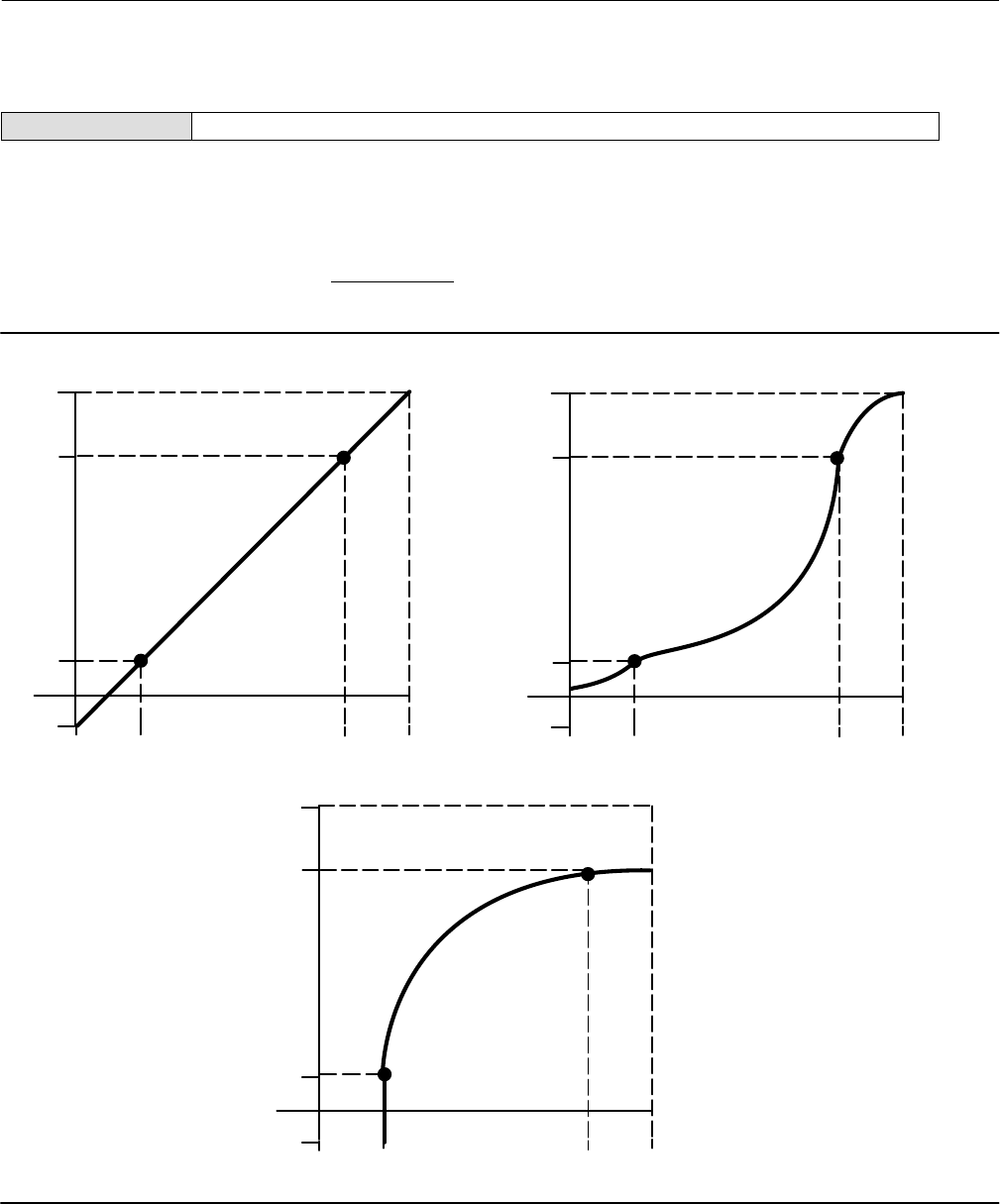
Instruction Manual
D103412X012
Detailed Setup—Transducer Block
January 2015
44
Custom Characterization Table
Field Communicator TB > Configure/Setup > Detailed Setup > Response Control > Custom Characterization Table
You can select from the three fixed input characteristics shown in figure 4‐1 or you can select a custom characteristic.
Figure 4‐1 shows the relationship between the travel target and travel set point for the fixed input characteristics.
You can specify 21 points on a custom characteristic curve. Each point defines a travel target, in % of ranged travel, for
a corresponding set point, in % of ranged set point. Set point values range from -25.0% to 125%. Before modification,
the custom characteristic is linear. You cannot modify the custom points if the Input Characterization (INPUT_CHAR
[50]) is set to custom.
Figure 4‐1. Travel Target Versus Ranged Set Point, for Various Input Characteristics (Zero Power Condition = Closed)
Travel Target, %
Set Point, %
-25 0 125100
Input Characteristic Linear
100
0
-25
125
-25 0 125100
Input Characteristic Equal Percentage
Travel Target, %
100
0
-25
125
Set Point, %
-25 0 125100
Input Characteristic Quick Opening
Travel Target, %
100
0
-25
125
A6535‐1
Set Point, %

Instruction Manual
D103412X012
Detailed Setup—Transducer Block
January 2015
45
Outblock Selection
Field Communicator TB > Configure/Setup > Detailed Setup > Response Control > Outblock Selection
Outblock Selection (OUTBLOCK_SEL [96]) defines which output function block will control the setpoint of the valve.
The output block that is not selected will shed its mode to reflect that it does not have control of the valve.
Alerts
The DVC6200f provides two levels of alerts; Instrument alerts and PlantWeb alerts.
Instrument Alert Conditions
Instrument Alert Conditions, when enabled, detect many operational and performance issues that may be of interest.
To view these alerts, the user must open the appropriate status screen on a host such as DeltaV, ValveLink software or
a Field Communicator.
PlantWeb Alerts
Some instrument alert conditions can also be used to trigger PlantWeb alerts that will be reported in Failed,
Maintenance or Advisory categories, as configured by the user. PlantWeb alerts, when enabled, can participate in the
DeltaV alarm interface tools such as the alarm banner, alarm list and alarm summary.
When a PlantWeb alert occurs, the DVC6200f sends an event notification and waits a specified period of time for an
acknowledgment to be received. This occurs even if the condition that caused the alert no longer exists. If the
acknowledgment is not received within the pre‐specified time‐out period, the event notification is retransmitted. This
reduces the possibility of alert messages getting lost.
PlantWeb alerts are mode‐based. Refer to table C‐1 for details.
Note
Additional details on setting up and using PlantWeb Alerts can be found in Appendix C of this manual.
Electronics Alerts
Field Communicator TB > Configure/Setup > Detailed Setup > Alerts > Elect Alerts
Drive Current
Drive Current—Drive Current (DRIVE_CURRENT [54]) displays the measured Drive Current actually flowing through
the I/P converter in percent of maximum drive.
Drive Current Alert—This alert is active when the difference between the expected Drive Current and the actual
Drive Current has exceeded the Drive Current Alert Time.
Drive Current Alert Enable—When enabled Drive Current Alert Enable activates the Drive Current Alert.
Drive Current Shutdown—The Shutdown Trigger (SHUTDOWN_TRIGGER [76.1]) permits enabling or disabling Self
Test Shutdown for the Drive Current alert. When enabled, and the alert condition is present, the transducer Actual

Instruction Manual
D103412X012
Detailed Setup—Transducer Block
January 2015
46
mode is placed Out of Service. The instrument will attempt to drive the valve to the Zero Power Condition and will
no longer execute transducer control function.
Drive Current Manual Recovery—Shutdown Recovery (SHUTDOWN_RECOVERY [76.2]) permits enabling or
disabling Automatic recovery from Self Test Shutdown. When enabled, the transducer block will return to Target
mode when Drive Current Shutdown clears. If not enabled, the transducer block will remain Out of Service until
power is removed and restored or the user changes the transducer block target mode to Manual or Auto. In any
case, the target mode will remain Out of Service, if the condition that caused the shutdown remains or until the
shutdown trigger is disabled.
Drive Current Alert Point—The Drive Current Alert Point (DRIVE_CURRENT_ALRT_PT [76.4]) is when the absolute
difference between the Drive Current and Drive Signal exceeds the set threshold for greater than the Drive Current
Alert Time.
Drive Current Alert Time—The Drive Current Alert Time (DRIVE_CURRENT_TIME [76.5]) is the maximum time that
the Drive Current Alert Point can be exceeded before the Drive Current Alert is active.
Drive Signal
Drive Signal—The Drive Signal (DRIVE_SIGNAL [53]) displays the commanded Drive Signal being sent to the I/P
converter as a percentage of the maximum drive.
Drive Signal Alert
The Drive Signal Alert is active if one of the following conditions exist:
Where Zero Power Condition is defined as closed:
Drive Signal < 10% and Calibrated Travel > 3%
Drive Signal > 90% and Calibrated Travel < 97%
Where Zero Power Condition is defined as open:
Drive Signal < 10% and Calibrated Travel < 97%
Drive Signal > 90% and Calibrated Travel > 3%
Drive Signal Alert Enable—When enabled Drive Signal Alert Enable activates the Drive Signal Alert.
Processor Impaired
Program Memory Alert—This alert is active if a pending Flash or NVM failure is present.
Program Memory Alert Enable—When enabled Program Memory Alert Enable activates the Program Memory Alert.
Program Memory Shutdown—The Shutdown Trigger (SHUTDOWN_TRIGGER [76.1]) permits enabling or disabling
Self Test Shutdown. When enabled, and the Program Memory Alert is active, the transducer Actual mode is placed
out of service. The instrument will attempt to drive the valve to the zero power condition and will no longer execute
transducer control function.
Program Memory Manual Recovery—Shutdown Recovery (SHUTDOWN_RECOVERY [76.2]) permits enabling or
disabling Automatic recovery from Self Test Shutdown. When enabled, the transducer block will return to Target
mode when the condition that caused Program Memory Shutdown clears. If not enabled, the transducer block will

Instruction Manual
D103412X012
Detailed Setup—Transducer Block
January 2015
47
remain Out of Service until power is removed and restored or the user changes the transducer block target mode to
Manual or Auto. In any case, the target mode will remain Out of Service, if the condition that caused the shutdown
remains or until the shutdown trigger is disabled.
Static Memory Alert—This alert is active if a failure occurs in the FRAM memory where the static parameters are
stored.
Static Memory Alert Enable—When enabled Static Memory Alert Enable activates the Static Memory Alert.
Static Memory Shutdown—The Shutdown Trigger (SHUTDOWN_TRIGGER [76.1]) permits enabling or disabling Self
Test Shutdown. When enabled, and the Static Memory Alert is active, the transducer Actual mode is placed out of
service. The instrument will attempt to drive the valve to the zero power condition and will no longer execute
transducer control function.
Static Memory Manual Recovery—Shutdown Recovery (SHUTDOWN_RECOVERY [76.2]) permits enabling or
disabling Automatic recovery from Self Test Shutdown. When enabled, the transducer block will return to Target
mode when the condition that caused Static Memory Shutdown clears. If not enabled, the transducer block will
remain Out of Service until power is removed and restored or the user changes the transducer block target mode to
Manual or Auto. In any case, the target mode will remain Out of Service, if the condition that caused the shutdown
remains or until the shutdown trigger is disabled.
Processor Alert—This alert is active if a failure occurs in the main processor.
Processor Alert Enable—When enabled Processor Alert Enable activates the Processor Alert.
I/O Processor Alert—This alert is active if a failure occurs in the I/O processor.
I/O Processor Shutdown—The Shutdown Trigger (SHUTDOWN_TRIGGER [76.1]) permits enabling or disabling Self
Test Shutdown. When enabled, and the I/O Processor Alert is active, the transducer Actual mode is placed out of
service. The instrument will attempt to drive the valve to the zero power condition and will no longer execute
transducer control function.
I/O Processor Man Recovery—Shutdown Recovery (SHUTDOWN_RECOVERY [76.2]) permits enabling or disabling
Automatic recovery from Self Test Shutdown. When enabled, the transducer block will return to Target mode when
the condition that caused I/O Processor Shutdown clears. If not enabled, the transducer block will remain Out of
Service until power is removed and restored or the user changes the transducer block target mode to Manual or
Auto. In any case, the target mode will remain Out of Service, if the condition that caused the shutdown remains or
until the shutdown trigger is disabled.
Configuration Alerts
Field Communicator TB > Configure/Setup > Detailed Setup > Alerts > Configuration Alerts
Output Block Timeout
Output Block Timeout Alert—This alert is active if the analog or discrete output block has not executed for longer
than the configured timeout.
Output Block Timeout Alert Enable—When enabled Output Block Timeout Alert Enable activates the Output Block
Timeout Alert.
Output Block Timeout Shutdown—The Shutdown Trigger (SHUTDOWN_TRIGGER [76.1]) permits enabling or
disabling Self Test Shutdown. When enabled, and the Output Block Timeout Alert is active, the transducer Actual

Instruction Manual
D103412X012
Detailed Setup—Transducer Block
January 2015
48
mode is placed out of service. The instrument will attempt to drive the valve to the zero power condition and will no
longer execute transducer control function.
Output Block Timeout Manual Recovery—Shutdown Recovery (SHUTDOWN_RECOVERY [76.2]) permits enabling or
disabling Manual recovery from Self Test Shutdown. When enabled, the transducer block will return to Target mode
when the condition that caused Output Block Timeout Shutdown clears. If not enabled, the transducer block will
remain Out of Service until power is removed and restored or the user changes the transducer block target mode to
Manual or Auto. In any case, the target mode will remain Out of Service if the condition that caused the shutdown
remains or until the shutdown trigger is disabled.
Output Block Timeout—The Output Block Timeout (OUTPUT_BLK_TIMEOUT [76.3]) is the maximum time between
updates from the AO or DO block to the transducer block setpoint.
Blocks Set to Default
Blocks Set to Defaults Alert—This alert is active if the resource block has undergone Restart with Defaults. This will
stay active until the transducer block is changed from Out of Service.
Blocks Set to Defaults Alert Enable—When enabled Blocks Set to Defaults Alert Enable activates the Blocks Set to
Default Alert.
Alert Key
The Alert Key (ALERT_KEY [4]) is the identification number of the plant unit. Devices in a loop or plant section can be
assigned with a common alert key to aid the operator in determining location of alerts.
Sensor Alerts
Field Communicator TB > Configure/Setup > Detailed Setup > Alerts > Sensor Alerts
Travel Sensor
Travel Sensor Alert—This alert is active if the Travel Sensor reading is outside the functional range, or the sensor
becomes disconnected.
Travel Sensor Alert Enable—When enabled Travel Sensor Alert Enable activates the Travel Sensor Alert.
Travel Sensor Shutdown—The Shutdown Trigger (SHUTDOWN_TRIGGER [76.1]) permits enabling or disabling Self
Test Shutdown. When enabled, and the Travel Sensor alert is active, the transducer Actual mode is placed out of
service. The instrument will attempt to drive the valve to the zero power condition and will no longer execute
transducer control function.
Travel Sensor Manual Recovery—Shutdown Recovery (SHUTDOWN_RECOVERY [76.2]) permits enabling or
disabling Manual recovery from Self Test Shutdown. When not enabled, the transducer block will return to Target
mode when Travel Sensor Shutdown clears. If enabled, the transducer block will remain Out of Service until power is
removed and restored or the user changes the transducer block target mode to Manual or Auto. In any case, the
target mode will remain Out of Service, if the condition that caused the shutdown remains or until the shutdown
trigger is disabled.
Pressure Sensors
Pressure A Sensor Alert—This alert is active if the Port A Pressure Sensor reading is outside the functional range.
Pressure A Sensor Alert Enable—When enabled Pressure A Sensor Alert Enable activates the Pressure A Sensor Alert.

Instruction Manual
D103412X012
Detailed Setup—Transducer Block
January 2015
49
Pressure A Sensor Shutdown—The Shutdown Trigger (SHUTDOWN_TRIGGER [76.1]) permits enabling or disabling
Self Test Shutdown. When enabled, and the Port A Pressure Sensor Alert is active, the transducer Actual mode is
placed out of service. The instrument will attempt to drive the valve to the zero power condition and will no longer
execute transducer control function.
Pressure A Sensor Manual Recovery—Shutdown Recovery (SHUTDOWN_RECOVERY [76.2]) permits enabling or
disabling Manual recovery from Self Test Shutdown. When not enabled, the transducer block will return to Target
mode when Pressure A Sensor Shutdown clears. If enabled, the transducer block will remain Out of Service until
power is removed and restored or the user changes the transducer block target mode to Manual or Auto. In any
case, the target mode will remain Out of Service, if the condition that caused the shutdown remains or until the
shutdown trigger is disabled.
Pressure B Sensor Alert—This alert is active if the Port B Pressure Sensor reading is outside the functional range.
Pressure B Sensor Alert Enable—When enabled Pressure B Sensor Alert Enable activates Pressure B Sensor Alert.
Supply Pressure Sensor Alert—This alert is active if the Supply Pressure Sensor reading is outside the functional
range.
Supply Pressure Sensor Alert Enable—When enabled Supply Pressure Sensor Alert Enable activates the Supply
Pressure Sensor Alert.
Pressure Fallback
Pressure Fallback Alert—This alert is active if a travel sensor failure or a gross travel deviation has resulted in fallback
to pressure control.
Pressure Fallback Alert Enable—When enabled Pressure Fallback Alert Enable activates the Pressure Fallback Alert.
Temperature Sensor
Temperature Sensor Alert—This alert is active if the Temperature Sensor reading is outside the functional range.
Temperature Sensor Alert Enable—When enabled Temperature Sensor Alert Enable activates the Temperature
Sensor Alert.
Environment Alerts
Field Communicator TB > Configure/Setup > Detailed Setup > Alerts > Environment Alerts
Supply Pressure
Supply—Supply (SUPPLY_PRESSURE.VALUE [35.2]) displays the instrument supply pressure in kPa, bar, or psi.
Supply Pressure Hi Alert—This alert is active when the supply pressure exceeds the Supply Pressure Hi Alert Point.
Supply Pressure Hi Alert Enable—When enabled Supply Pressure Hi Alert Enable activates Supply Pressure Hi Alert.
Supply Pressure Hi Alert Point—The Supply Pressure Hi Alert is active when supply pressure exceeds the Supply
Pressure Hi Alert Point (SUP_PRES_HI_ALRT_PT [76.8]).
Supply Pressure Lo Alert—This alert is active when the supply pressure is lower than the Supply Pressure Lo Alert
Point.

Instruction Manual
D103412X012
Detailed Setup—Transducer Block
January 2015
50
Supply Pressure Lo Alert Enable—When enabled Supply Pressure Lo Alert Enable activates Supply Pressure Lo Alert.
Supply Pressure Lo Alert Point—Supply Pressure Lo Alert Point (SUP_PRES_LO_ALRT_PT [76.9]). When the supply
pressure falls below the supply pressure alert point, the supply pressure alert is active. To disable the supply
pressure alert, set Supply Pressure Alert Point to zero.
Temperature Limit
Temperature—Degrees Fahrenheit or Celsius. The temperature (TEMPERATURE [48]) is measured from a sensor
mounted on the digital valve controller's printed wiring board.
Temperature Hi Alert—This alert is active if the temperature is greater than the Temperature Hi Alert Point.
Temperature Hi Alert Enable—When enabled Temperature Hi Alert Enable activates the Temperature Hi Alert.
Temperature Hi Alert Point—The Temperature Hi Alert is active when the instrument temperature exceeds the
Temperature Hi Alert Point (TEMP_HI_ALRT_PT [76.6]).
Temperature Lo Alert—This alert is active if the temperature is lower than the Temperature Lo Alert Point.
Temperature Lo Alert Enable—When enabled Temperature Lo Alert Enable activates the Temperature Lo Alert.
Temperature Lo Alert Point—The Temperature Lo Alert is active when the instrument temperature is lower than the
Temperature Lo Alert Point (TEMP_LO_ALRT_PT [76.7]).
Travel Alerts
Field Communicator TB > Configure/Setup > Detailed Setup > Alerts > Travel Alerts
Note
The alerts contained in this section are valid for both travel and pressure control.
Travel Target
Travel target is the output from the characterization function.
Travel
Travel (TRAVEL.VALUE [34.2]) displays the actual position of the valve in percent (%) of calibrated travel.
Travel Deviation
Travel Deviation—Travel Deviation (TRAVEL_DEVIATION [52]) displays the absolute difference in percent between
Travel Target and Actual Travel.
Travel Deviation Alert—This alert is active if the Travel deviation exceeds the Travel Deviation Alert Point by more
than the Travel Deviation Time.
Travel Deviation Alert Enable—When enabled Travel Deviation Alert Enable actives the Travel Deviation Alert.

Instruction Manual
D103412X012
Detailed Setup—Transducer Block
January 2015
51
Travel Deviation Alert Point—The Travel Deviation Alert Point (TVL_DEV_ALRT_PT [77.1]) is the alert point for the
difference, expressed in percent (%), between the travel target and the actual travel. When the difference exceeds
the alert point for more than the Travel Deviation Time, the Travel Deviation Alert is set.
Travel Deviation Time—Travel Deviation Time (TVL_DEV_TIME [77.2]) is the time, in seconds, that the travel
deviation must exceed the Travel Deviation Alert Point before the alert is set.
Travel Deviation Deadband—Travel Deviation Deadband (TVL_DEV_DB [77.3]) is the travel in percent threshold (%)
of ranged travel required to clear a Travel Deviation alert, once it has been set. See figure 4‐2.
Figure 4‐2. Travel Hi Alert Deadband
ALERT IS CLEARED
ALERT IS SET
TRAVEL ALERT
HIGH POINT
TRAVEL ALERT
DEADBAND
A6532
Travel Limit
Travel Hi Hi Alert—This alert is active if the Travel exceeds the Travel Hi Hi Alert point.
Travel Hi Hi Alert Enable—When enabled Travel Hi Hi Alert Enable activates the Travel Hi Hi Alert.
Travel Hi Hi Alert Point—Travel Hi Hi Alert Point (TVL_HI_HI_ALRT_PT [77.18]) is the value of the travel, in percent
(%) of ranged travel, which, when exceeded, sets the Travel Alert Hi Hi alert.
Travel Hi Hi Deadband—Travel Hi Hi Deadband (TVL_HI_HI_DB [77.19]) is the travel, in percent (%) of ranged travel,
required to clear a Travel Hi Hi alert, once it has been set. See figure 4‐2.
Travel Lo Lo Alert—This alert is active if the Travel is lower than the Travel Lo Lo Alert point.
Travel Lo Lo Alert Enable—When enabled Travel Lo Lo Alert Enable activates the Travel Lo Lo Alert.
Travel Lo Lo Alert Point—The Travel Lo Lo alert is set when the value of the travel, in percent (%) of ranged travel,
goes below the Travel Lo Lo Alert Point (TVL_LO_LO_ALRT_PT [77.12]).
Travel Lo Lo Deadband—Travel Lo Lo Deadband (TVL_LO_LO_DB [77.13]) is the travel, in percent (%) of ranged
travel, required to clear a Travel Lo Lo alert once it has been set. See figure 4‐3.
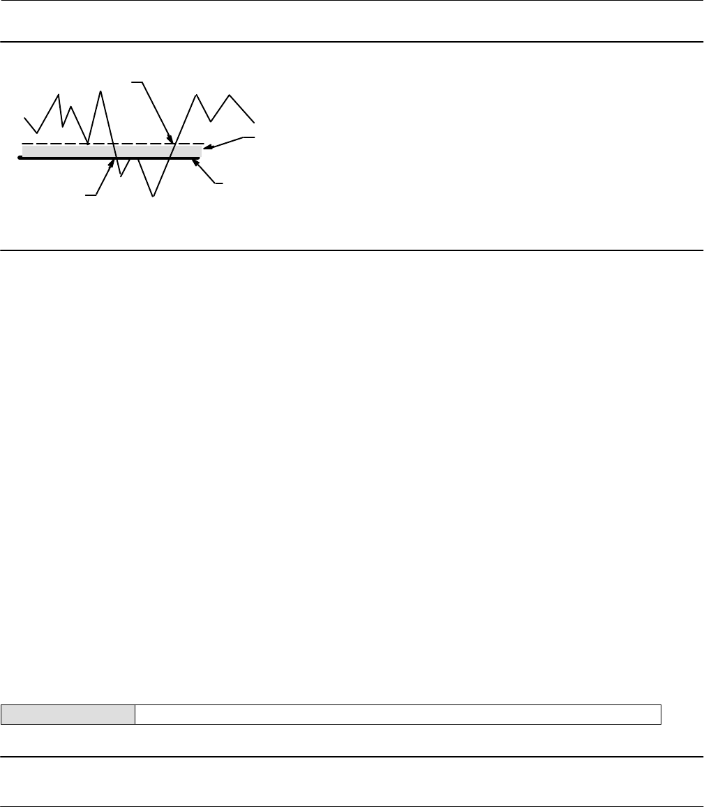
Instruction Manual
D103412X012
Detailed Setup—Transducer Block
January 2015
52
Figure 4‐3. Travel Lo Alert Deadband
ALERT IS CLEARED
ALERT IS SET
TRAVEL ALERT
LO POINT
TRAVEL ALERT
DEADBAND
A6532‐1
Travel Hi/Lo
Travel Hi Alert—This alert is active if the Travel exceeds the Travel Hi Alert point.
Travel Hi Alert Enable—When enabled Travel Hi Alert Enable activates the Travel Hi Alert.
Travel Hi Alert Point—Travel Hi Alert is set if the ranged travel rises above the Travel Hi Alert Point (TVL_HI_ALRT_PT
[77.16]). Once the alert is set, the ranged travel must fall below the alert high point set by the Travel Hi Deadband
before the alert is cleared. See figure 4‐2.
Travel Hi Deadband—Travel Hi Deadband (TVL_HI_DB [77.17]) is the travel, in percent (%) of ranged travel, required
to clear a Travel Hi Alert, once it has been set. See figure 4‐2.
Travel Lo Alert—This alert is active if the Travel is lower than the Travel Lo Alert point.
Travel Lo Alert Enable—When enabled Travel Lo Alert Enable activates the Travel Lo alert.
Travel Lo Alert Point—The Travel Alert Lo alert is set when the value of the travel, in percent (%) of ranged travel,
goes below the Travel Lo Alert Point (TVL_LO_ALRT_PT [77.14]).
Travel Lo Deadband—Travel Lo Deadband (TVL_LO_DB [77.15]) is the travel, in percent (%) of ranged travel,
required to clear a travel lo alert, once it has been set. See figure 4‐3.
Proximity Alerts
Field Communicator TB > Configure/Setup > Detailed Setup > Alerts > Prox Alerts
Note
See page 179 for additional details on using Proximity detection.
Travel
Travel displays the actual position of the valve in percent (%) of calibrated travel.

Instruction Manual
D103412X012
Detailed Setup—Transducer Block
January 2015
53
Travel Open
Travel Open Alert—This alert is active if the Travel is greater than the Travel Open Alert Point.
Travel Open Alert Enable—When enabled Travel Open Alert Enable activates the Travel Open Alert.
Travel Open Alert Point—Travel Open Alert Point (TVL_OPEN_ALRT_PT [77.8]) is the value of the travel in percent
(%) or ranged travel, which, when exceeded, sets the Travel Open Alert.
Travel Open Deadband—Travel Open Deadband (TVL_OPEN_DB [77.9]) is the travel in percent (%) of ranged travel
required to clear a Travel Open alert, once it has been set.
Travel Closed
This alert is active if the Travel is lower than the Travel Closed Alert Point.
Travel Closed Alert—This alert is active is the Travel goes below the Travel Closed Alert Point.
Travel Closed Alert Enable—When enabled Travel Closed Alert Enable activates the Travel Closed Alert.
Travel Closed Alert Point—The Travel Closed Alert is set when the value of the travel, in percent (%) of ranged travel,
goes below the Travel Closed Alert Point (TVL_CLOSED_ALRT_PT [77.10]).
Travel Closed Deadband—Travel Closed Deadband (TVL_CLOSED_DB [77.11]) is the travel in percent (%) of ranged
travel required to clear a Travel Closed alert, once it has been set.
Proximity
Proximity Hi Hi Alert—This alert is active if the Travel is within the detection band set by the Travel Hi Hi Alert Point
and the Travel Hi Hi Deadband.
Proximity Hi Hi Alert Enable—When enabled Proximity Hi Hi Alert Enable activates the Proximity Hi Hi Alert.
Proximity Hi Alert—This alert is active if the Travel is within the detection band set by the Travel Hi Alert Point and
the Travel Hi Deadband.
Proximity Hi Alert Enable—When enabled Proximity Hi Alert Enable activates the Proximity Hi Alert.
Proximity Lo Alert—This alert is active if the Travel is within the detection band set by the Travel Lo Alert Point and
the Travel Lo Deadband.
Proximity Lo Alert Enable—When enabled Proximity Lo Alert Enable activates the Proximity Lo Alert.
Proximity Lo Lo Alert—This alert is active if the Travel is within the detection band set by the Travel Lo Lo Alert Point
and the Travel Lo Lo Deadband.
Proximity Lo Lo Alert Enable—When enabled Proximity Lo Lo Alert Enable activates the Proximity Lo Lo Alert.
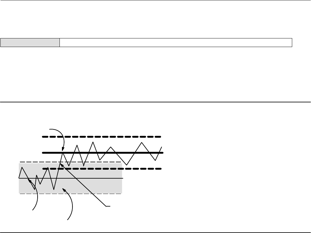
Instruction Manual
D103412X012
Detailed Setup—Transducer Block
January 2015
54
Travel History Alerts
Field Communicator TB > Configure/Setup > Detailed Setup > Alerts > Travel History Alerts
Cycle Counter
Cycle Counter—The Cycle Counter (CYCLE_COUNT [73]) records the number of times the travel changes direction.
The change in direction must occur after the deadband has been exceeded before it can be counted as a cycle. See
figure 4‐4. You can reset the Cycle Counter by configuring it as zero.
Figure 4‐4. Cycle Counter Deadband (set at 10%)
Deadband Reference
Deadband (+/- 5%)
Deadband exceeded, and direction
changed, new Reference Point
established
Point
Point at which
cycle is counted
A6533‐1
Cycle Counter Alert—This alert is active if the Cycle Counter exceeds the Cycle Counter Alert Point. It is cleared after
you reset the Cycle Counter to a value less than the alert point.
Cycle Counter Alert Enable—When enabled Cycle Counter Alert Enable activates checking of the difference between
the Cycle Counter and the Cycle Counter Alert point.
Cycle Counter Alert Point—Cycle Counter Alert Point (CYCLE_COUNT_ALRT_PT [77.6]) is the value of the Cycle
Counter, in cycles, which, when exceeded, sets the Cycle Counter Alert.
Cycle Counter Deadband—Cycle Counter Deadband (CYCLE_COUNT_DB [77.7]) is the area around the travel
reference point, in percent (%) of ranged travel, that was established at the last increment of the Cycle Counter. This
area must be exceeded before a change in travel direction can be counted as a cycle. See figure 4‐4.
Travel Accumulator
Travel Accumulator—Travel Accumulator (TRAVEL_ACCUM [72]) records the total change in travel, in percent (%) of
ranged travel, since the accumulator was last cleared. The value of the Travel Accumulator increments when the
magnitude of the change exceeds the Travel Accumulator Dead‐band. See figure 4‐5. You can reset the Travel
Accumulator by configuring it to zero.
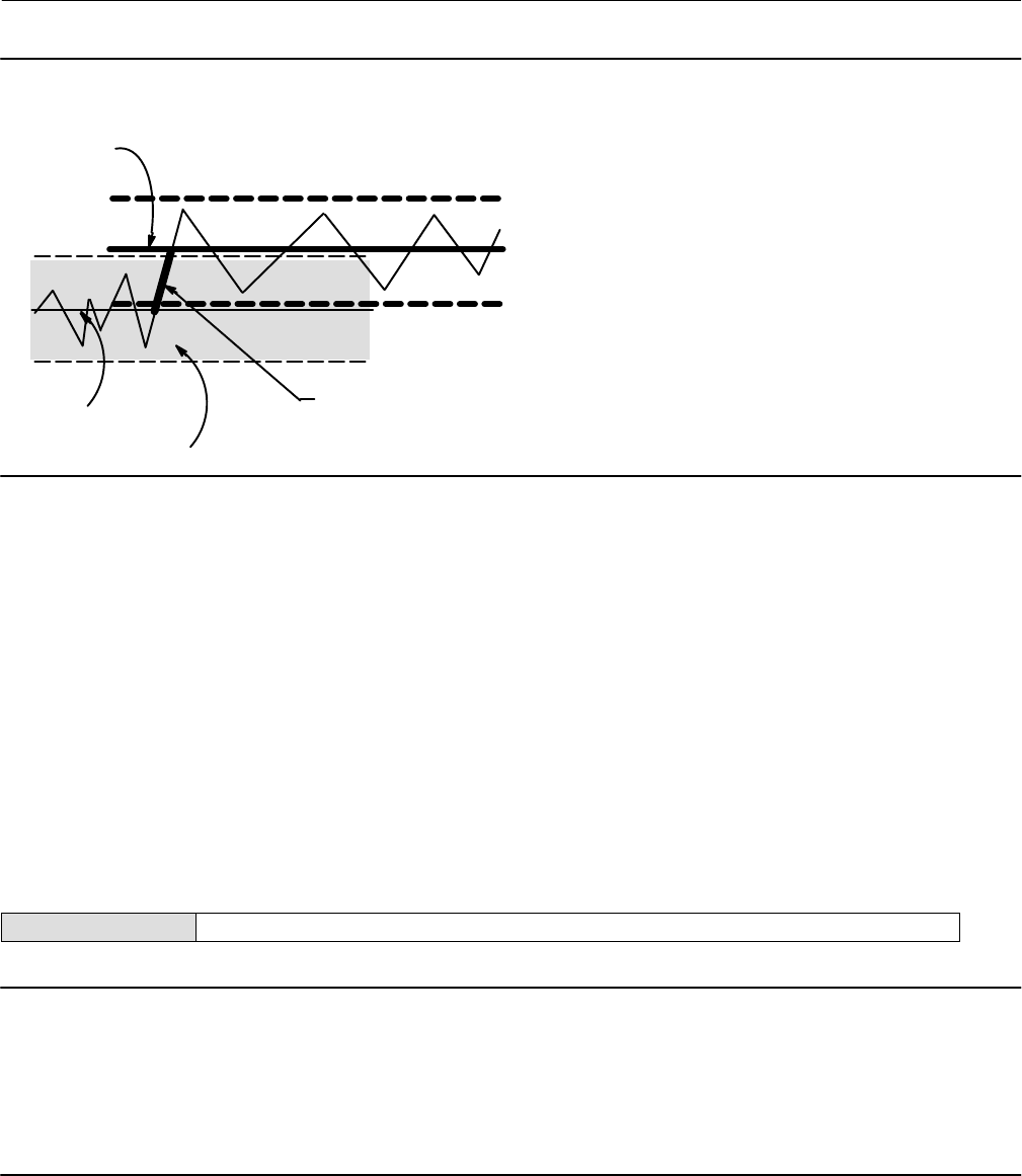
Instruction Manual
D103412X012
Detailed Setup—Transducer Block
January 2015
55
Figure 4‐5. Travel Accumulator Deadband (set at 10%)
Deadband Reference
Deadband (+/- 5%)
Deadband exceeded,
new Reference Point
established
Point
This amount of change is
added to the Travel
Accumulator
A6534
Travel Accumulator Alert—This alert is active if the Travel Accumulator exceeds the Travel Accumulator Alert Point.
The Travel Accumulator Alert is set when the Travel Accumulator value exceeds the Travel Accumulator Alert Point.
It is cleared after you reset the Travel Accumulation to a value less than the alert point.
Travel Accumulator Alert Enable—When enabled Travel Accumulator Alert Enable activates checking of the
difference between the Travel Accumulator value and the Travel Accumulator Alert Point.
Travel Accumulator Alert Point—Travel Accumulator Alert Point (TVL_ACCUM_ALRT_PT [77.4]) is the value of the
Travel Accumulator, in percent (%) of ranged travel, which, when exceeded, sets the Travel Accumulator Alert.
Travel Accumulator Deadband—Travel Accumulator Deadband (TVL_ACCUM_DB [77.5]) is the area around the
travel reference point, in percent (%) of ranged travel, that was established at the last increment of the
accumulator. This area must be exceeded before a change in travel can be accumulated. See figure 4‐5.
Performance Alerts
Field Communicator TB > Configure/Setup > Detailed Setup > Alerts > Performance Alerts
Note
Performance Alerts are only available with a PD tier instrument. Additionally, for the PD alerts to function properly:
The transducer block mode must not be out of service.
The travel/pressure control state must be in travel control mode, and
Bench Set Hi, Bench Set Lo, and Nominal Supply Pressure must be set in the Spec Sheets, then enable the Performance
Information instrument alert (PERF_ENABLE [75.7]).
PD Inside Status
PD Inside Status shows the status of Performance Diagnostics.

Instruction Manual
D103412X012
Detailed Setup—Transducer Block
January 2015
56
PD Run
PD Run enables or disables Performance Diagnostics in the instrument (PD Inside). Selecting PD Off disables PD Inside.
Selecting PD On enables PD Inside.
Performance Critical
Performance Critical Alert—This alert is active if the instrument is no longer able to control the valve or performance
has been dramatically reduced.
Performance Critical Alert Enable—When enabled Performance Critical Alert Enable activates the Performance
Critical Alert.
Performance Reduced
Performance Reduced Alert—This alert is active if the instrument has detected a reduction in performance.
Performance Reduced Alert Enable—When enabled Performance Reduced Alert Enable activates the Performance
Reduced Alert.
Performance Information
Performance Information Alert—This alert is active if the instrument has detected a condition that may pertain to
control performance.
Performance Information Alert Enable—When enabled Performance Information Alert Enable activates the
Performance Information Alert.
PlantWeb Alert Enable
Field Communicator TB > Configure/Setup > Detailed Setup > Alerts > PlantWeb Alert Enable
Failed Enable—Failed Enable (FAILED_ENABLE [62]) enables or disables conditions that can cause a failed alert. A
failed alert indicates a failure within the device that will make the device or some part of the device non‐operational.
Table C‐2 lists the available PlantWeb alerts.
Maintenance Enable—Maintenance Enable (MAINT_ENABLE [63]) enables or disables conditions that can cause a
maintenance alert. A maintenance alert indicates the device or some part of the device needs maintenance soon.
Table C‐2 lists the available PlantWeb alerts.
Advise Enable—Advise Enable (ADVISE_ENABLE [64]) enables or disables conditions that can cause an advisory alert.
An advisory alert indicates informative conditions that do not have a direct impact on the device's primary
functions. Table C‐2 lists the available PlantWeb alerts.
PlantWeb Alert Reporting
Field Communicator TB > Configure/Setup > Detailed Setup > Alerts > PlantWeb Alert Reporting
Failed Suppress—Failed Suppress (FAILED_MASK [65]) determines which of the failed alert conditions are
suppressed so that they are not reported. Even if reporting is suppressed, the bit in Failed Active (FAILED_ACTIVE
[59]) is still set.
Maintenance Suppress—Maintenance Suppress (MAINT_MASK [66]) determines which of the maintenance alert
conditions are suppressed so that they are not reported. Even if reporting is suppressed, the bit in Maintenance
Active (MAINT_ACTIVE [60]) is still set.

Instruction Manual
D103412X012
Detailed Setup—Transducer Block
January 2015
57
Advise Suppress—Advise Suppress (ADVISE_MASK [67]) determines which of the advise alert conditions are
suppressed so that they are not reported. Even if reporting is suppressed, the bit in Advise Active (ADVISE_ACTIVE
[61]) is still set.
Instrument
Field Communicator TB > Configure/Setup > Detailed Setup > Instrument
Tag Description—The Tag Description (TAG_DESC [2]) is a 32 character description used to assign a unique
description to each block within the digital valve controller to describe the intended application for the block.
Pressure Units—Define the output and supply pressure units (PRESSURE_UNITS [90]) in either psi, bar, or kPa.
Temperature Units—Enter the temperature units (TEMPERATURE_UNITS [89]) in degrees Fahrenheit or Celsius. The
temperature is measured from a sensor mounted on the digital valve controller's printed wiring board.
Travel Units—Define the units for valve travel (TVL_UNITS [91]) in inches, centimeters, millimeters or degrees.
Length Units—Define the units for valve dimensions (LENGTH_UNITS [92]) in inches, centimeters, or millimeters.
Area Units—Define the units for actuator area (AREA_UNITS [93]) in inches2, centimeter2 or millimeter2.
Spring Rate Units—Define the units for actuator spring rate (SPRING_RATE_UNITS [94]) in lbs/in2 or N/M.
Relay Type—Enter the Relay Type (RELAY_TYPE [42.5]).There are three categories of relays that result in
combinations from which to select.
Relay Type: The relay type is printed on the label affixed to the relay body:
A = double‐acting or single acting
B = single‐acting, reverse
C= single‐acting, direct
Lo Bleed: The label affixed to the relay body indicates it is a low bleed version.
Zero Power Condition—Zero Power Condition (ZERO_PWR_COND [42.2]) identifies whether the valve is open or
closed when instrument power is lost. If you are unsure how to set this parameter, disconnect the segment loop
power to the instrument. The resulting valve travel is the Zero Power Condition.
Maximum Supply Pressure—Enter the maximum supply pressure (MAX_SUPP_PRESS [42.6]) in psi, bar, or kPa,
depending on what was selected for pressure units.
Calibration Person—Name of the person performing last calibration (XD_CAL_WHO [31]).
Calibration Location—Indicates the location of the last instrument calibration (XD_CAL_LOC [29]).
Calibration Date—Enter a date with the format MM/DD/YY. Date is a user‐defined variable that provides a place to
save the date of the last calibration (XD_CAL_DATE [30]).
Last Calibration Type—Indicates the type of the last calibration performed on the instrument. Possible values are:
Not Calibrated, Single Point Calibration, Auto Calibration, Manual Calibration.

Instruction Manual
D103412X012
Detailed Setup—Transducer Block
January 2015
58
Valve and Actuator
Field Communicator TB > Configure/Setup > Detailed Setup > Valve and Actuator
Valve
Valve Manufacturer—Enter the identification number of the manufacturer of the valve (VALVE_MAN_ID [25]) on
which the instrument is mounted. Select from the drop‐down list or enter the manufacturer's identification number
as defined by the Fieldbus Foundation. For Fisher, the manufacturer ID hex value is 005100.
Valve Model Number—Enter the valve model number (VALVE_MODEL_NUM [26]), (design letter or type number)
for the valve on which the instrument is mounted.
Valve Serial Number—Enter the serial number of the valve (VALVE_SN [27]) on which the instrument is mounted.
Valve Style—Enter the type of valve (VALVE_TYPE [28]), sliding‐stem or rotary, on which the instrument is mounted.
Valve Size—Enter the size of the valve (VALVE_SIZE [83.1]) on which the instrument is mounted.
Valve Class—Enter the valve pressure class rating (VALVE_CLASS [83.2]).
Rated Travel—Enter the valve rated travel (RATEDTRAVEL [83.3]) in inches or mm for sliding-stem valves, or in
degrees of rotation for rotary valves.
Actual Travel—Enter the actual travel (ACTUAL_TRAVEL [83.4]) in inches or mm for sliding-stem valves, or in degrees
of rotation for rotary valves.
Shaft Stem Diameter—Enter the valve stem diameter (SHAFT_STEM_DIA [83.5]) in inches or millimeters.
Packing Type—Enter the valve packing construction (PACKING_TYPE [83.6]).
Inlet Pressure—Enter the valve inlet pressure (INLET_PRESSURE [83.7]).
Outlet Pressure—Enter the valve outlet pressure (OUTLET_PRESSURE [83.8]) in psig, kPa, Bar, inHg, inH2O, or
kg/cm2.
Trim
Seat Type—Enter the valve seat type (SEAT_TYPE [84.1]).
Leak Class—Enter the valve leak class (LEAK_CLASS [84.2]).
Port Diameter—Enter the valve port diameter (PORT_DIAMETER [84.3]) in inches or mm.
Port Type—Enter the valve port type (PORT_TYPE [84.4]).
Flow Direction—Enter the flow direction (FLOWDIRECTION [84.5]) through the valve.
Push Down To—Enter the effect on valve movement when the stem is moved down (PUSH_DOWN_TO [84.6]).
Flow Tends To—Enter the effect on valve travel with increasing flow (FLOW_TENDS_TO [84.7]).
Unbalanced Area—Enter the valve unbalanced area (UNBALANCED_AREA [84.8]) in in2 or mm2.

Instruction Manual
D103412X012
Detailed Setup—Transducer Block
January 2015
59
Actuator
Actuator Manufacturer—Enter the manufacturer's identification number (ACT_MAN_ID [22]) of the actuator on
which the instrument is mounted. Select from the drop‐down list or enter the manufacturer's identification number
as defined by the Fieldbus Foundation. For Fisher, the manufacturer ID hex value is 005100.
Actuator Model Number—Enter the type number for the actuator (ACT_MODEL_NUM [23]) on which the
instrument is mounted.
Actuator Style—Select the Actuator Style (ACTUATOR_STYLE [42.1]), spring & diaphragm, piston double‐acting
without spring, piston single‐acting with spring, or piston double‐acting with spring.
Actuator Serial Number—Enter the serial number (ACT_SN [24]) for the actuator on which the instrument is
mounted.
Actuator Size—Enter the size of the actuator (ACTUATOR_SIZE [85.1]) on which the instrument is mounted.
Actuator Fail Action—Sets actuator action to be performed upon loss of actuator air pressure (ACT_FAIL_ACTION
[21]).
View / Edit Feedback Connection—Refer to table 4‐10 for Feedback Connection options. Choose the assembly that
matches the actuator travel range.
Note
As a general rule, do not use less than 60% of the magnet assembly travel range for full travel measurement. Performance will
decrease as the assembly is increasingly subranged.
The linear magnet assemblies have a valid travel range indicated by arrows molded into the piece. This means that the hall sensor
(on the back of the DVC6200f housing) has to remain within this range throughout the entire valve travel. The linear magnet
assemblies are symmetrical. Either end may be up.
Table 4‐10. Feedback Connection Options
Magnet Assembly Travel Range
mm Inch Degrees
SStem #7 4.2-7 0.17-0.28 -
SStem #19 8-19 0.32-0.75 -
SStem #25 20-25 0.76-1.00 -
SStem #38 26-38 1.01-1.50 -
SStem #50 39-50 1.51-2.00 -
SStem #110 51-110 2.01-4.125 -
SStem #210 110-210 4.125-8.25 -
SStem #1 Roller > 210 > 8.25 60-90
RShaft Window #1 - - 60-90
RShaft Window #2 - - 60-90
RShaft End Mount - - 60-90
Travel Sensor Motion
WARNING
If you answer YES to the prompt for permission to move the valve when setting the Travel Sensor Motion, the instrument
will move the valve through its full travel range. To avoid personal injury and property damage caused by the release of

Instruction Manual
D103412X012
Detailed Setup—Transducer Block
January 2015
60
pressure or process fluid, isolate the valve from the process and equalize pressure on both sides of the valve or bleed off the
process fluid.
Travel Sensor Motion (TRAVEL_SEN_MOTION [42.3]) establishes the proper valve travel sensor (feedback)
rotation/movement. For quarter‐turn actuators determine rotation by viewing the rotation of the magnet assembly
from the back of the instrument.
Note
Travel Sensor Motion in this instance refers to the motion of the magnet assembly. Note that the magnet assembly may be
referred to as a magnetic array in user interface tools.
For instruments with relay A or C If increasing air pressure at output A causes the magnet assembly to move up, or the
actuator shaft to rotate counterclockwise, enter “Towards Top of Instrument/CCW.” If it causes the magnet assembly
to move down, or the actuator shaft to rotate clockwise, enter “Away From Top of Instrument/CW.” For instruments
with relay B.
For instruments with relay B If decreasing air pressure at output B causes the magnet assembly to move up, or the
actuator shaft to rotate counterclockwise, enter “Towards Top of Instrument/CCW.” If it causes the magnet assembly
to move down, or the actuator shaft to rotate clockwise, enter “Away From Top of Instrument/CW.”
Lever Style—Enter the lever style (LEVER_STYLE [85.10]) for rotary actuators as either Pivot Point or Rack and Pinion.
Lever Arm Length—Defines the lever arm length (MOMENT_ARM [85.11]) for rotary actuators.
Effective Area—Enter the actuator effective area (EFFECTIVE_AREA [85.2]) in in2, cm2, or mm2.
Air—Select Opens or Closes, indicating the effect of increasing air pressure (AIR [85.3]) on the valve travel.
Upper Bench Set—Enter the upper actuator operating pressure (UPPER_BENCH_SET [85.5]).
Lower Bench Set—Enter the lower actuator operating pressure (LOWER_BENCH SET [85.4]).
Nominal Supply Pressure—Enter the nominal instrument supply pressure (NOMINAL_SUPPLY PRESSURE [85.6]).
Spring Rate—Enter the actuator spring rate (SPRING_RATE [85.7]) in lbsin or Nm.
Reference
Trim Style 1—Enter the valve trim style (TRIM_STYLE_1 [84.9]).
Trim Style 2—Enter the valve trim style (TRIM_STYLE_2 [84.10]).
Stroking Time Open—Enter the time required to stroke the valve from closed to open (STROKING_TIME_OPEN
[85.8]).
Stroking Time Close—Enter the time required to stroke the valve from open to close (STROKING_TIME_CLOSE
[85.9]).
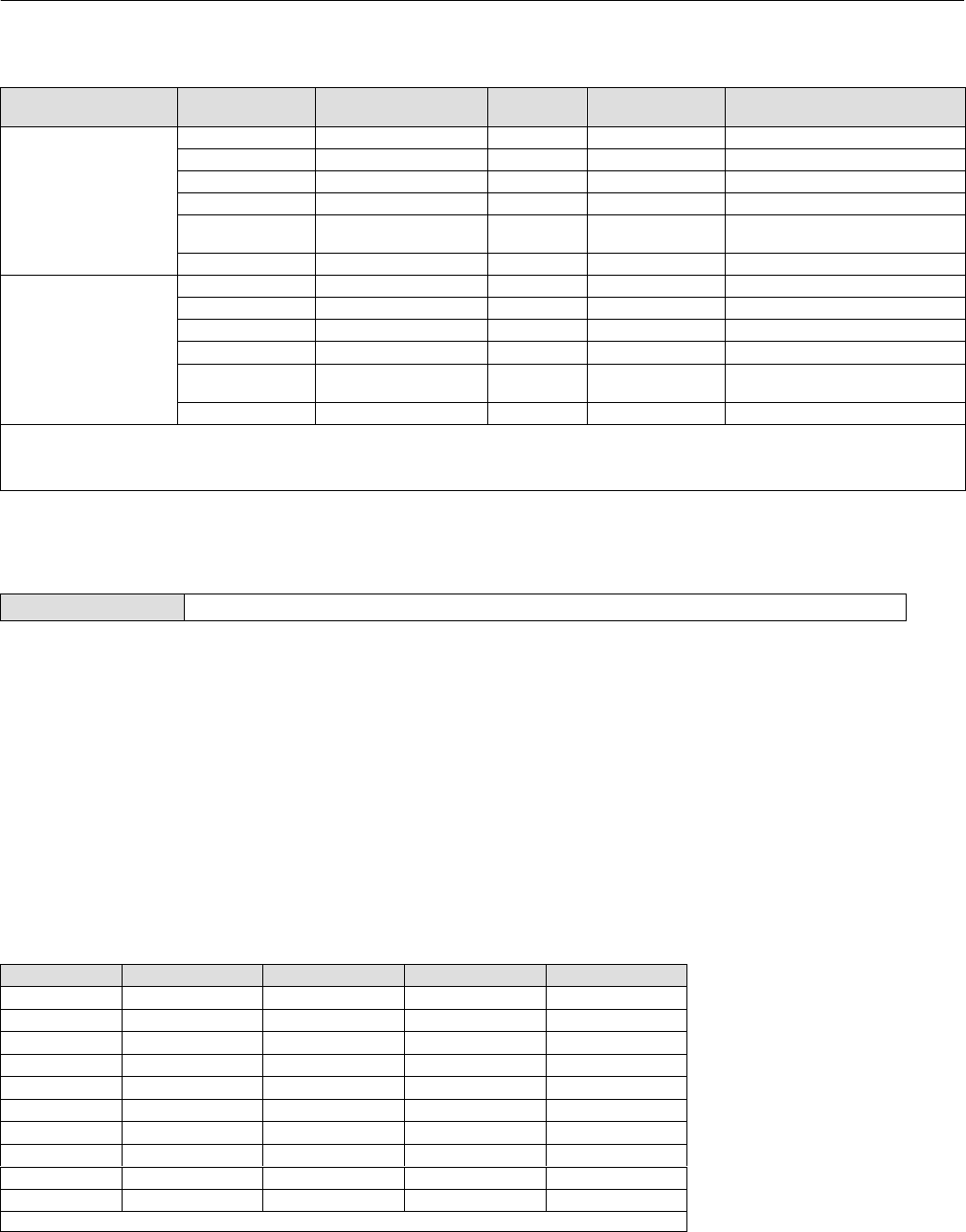
Instruction Manual
D103412X012
Detailed Setup—Transducer Block
January 2015
61
Table 4‐11. Output Block PV Status
FEATURE_SEL
PW Alarms Set PV Status
Transducer Mode,
Actual
Active PlantWeb
Alarms
AO / DO
PV Status(2)
AO / DO
PV Substatus
AO/DO PV
Limit Substatus(1)
Enabled
OOS X Bad Device Failure Constant
Man X Bad Non‐specific Constant
Auto Fail Uncertain Subnormal See table 4‐12
Auto Maintenance, no Fail Uncertain Non‐specific See table 4‐12
Auto Advisory, no Fail, no
Maintenance Good Advisory See table 4‐12
Auto None Good Non‐Specific See table 4‐12
Not Enabled
OOS X Bad Device Failure Constant
Man X Bad Non‐Specific Constant
Auto Fail Good Non‐Specific See table 4‐12
Auto Maintenance, no Fail Good Non‐Specific See table 4‐12
Auto Advisory, no Fail, no
Maintenance Good Non‐Specific See table 4‐12
Auto None Good Non‐Specific See table 4‐12
NOTES:
X = No Effect
1. PV limit substatus reflects only READBACK limit substatus. SP limit substatus reflects only out block rate limits.
2. Firmware Revision 1.1 and earlier will set AO/DO PV Status to Bad if Feedback Sensor has failed, i.e.; Travel Sensor Fail. However, if the Travel Sensor fails, and the instrument falls back to
pressure, PV Status will remain good.
MAI Channel Map
Field Communicator TB > Configure/Setup > Detailed Setup > MAI Channel Map
Allows the user to specify which transducer block parameter is available through each of the MAI Block channels
(MAI_CHANNEL_1 through MAI_CHANNEL_8 [95.1 through 95.8]). Transducer block parameters available to each
channel:
11 = FINAL_VALUE
12 = TRAVEL_TARGET
13 = FINAL_POSITION_VALUE
14 = TRAVEL
15 = SUPPLY_PRESS
16 = ACT_PRESS_A
17 = ACT_PRESS_B
18 = ACT_PRESS_DIFF
19 = DRIVE_SIGNAL
10 = TRAVEL_DEVIATION
11 = TEMPERATURE
12 = CYCLE_COUNT
13 = TRAVEL_ACCUM
Table 4‐12. Limit Sub Status
Out Block Transducer Mode In Cutoff Region Rate Limited Limit Sub‐Status
AO, DO OOS X X Constant
AO, DO MAN X X Constant
AO AUTO High X High Limited
AO AUTO Low X Low Limited
AO AUTO X High High Limited
AO AUTO X Low Low Limited
AO AUTO None None Not Limited
DO AUTO X High High Limited
DO AUTO X Low Low Limited
DO AUTO X None Not Limited
NOTE: X = No Effect

Instruction Manual
D103412X012
Detailed Setup—Transducer Block
January 2015
62
Alert Handling
Field Communicator TB > Configure/Setup > Detailed Setup > Alert Handling
PlantWeb Alert Simulate
When enabled, PlantWeb Alert Simulate (PWA_SIMULATE [39]) allows the user to write to the following PlantWeb and
Instrument alert parameters; Failed Active, Maintenance Active, Advise Active, Environment Active, Travel Active,
Proximity Active, Travel History Active, Performance Active, PD Event Active, PD Detail 1 Active, PD Detail 2 Active, PD
Detail 3 Active, PD Detail 4 Active, PD Detail 5 Active, PD Detail 6 Active. This provides a way to simulate these alerts
for testing. In order to enable PWA Simulate, the Aux Terminal must be jumpered.
PlantWeb Alert Simulate is cleared on a power cycle. It can also be cleared manually, or by removing the Aux terminal
jumper.
Simulate Active Alerts
Failed Active—Permits simulating an active Failed alarm (FAILED_ACTIVE [59]).
Maintenance Active—Permits simulating an active Maintenance alarm (MAINT_ACTIVE [60]).
Advise Active—Permits simulating an active Advisory alarm (ADVISE_ACTIVE [61]).
PlantWeb Alert Handling
PlantWeb Alerts Set PV Status—When selected, PlantWeb alerts will set the PV status according to table 4‐11.
Block Error Reporting—When enabled, the AO or DO BLOCK_ERR [6] parameter will report PlantWeb Alerts. the
same as Block Error in the resource block.
Block Error bit 6 (Device Needs Maintenance Soon) will report any active PlantWeb Maintenance Alert.
Block Error bit 13 (Device Needs Maintenance Now) will report any active PlantWeb Failed Alert.
Block Errors
Table 4‐13 lists conditions reported in the BLOCK_ERR [6] and XD_ERR [11] parameters. Conditions in italics are not
applicable for the transducer block and are provided only for your reference.
Table 4‐13. Transducer Block BLOCK_ERR and XD_ERROR Conditions
Condition Number Condition Name and Description
0Other ‐ (N/A)
1Block Configuration Error ‐ Indicates that one of the following parameters have been configured out of the proper range: 15,
16, 47.1, 47.2, 46.3, 46.5, 42.7, 42.8.
2Link Configuration Error ‐ (N/A)
3Simulate Active ‐ Indicates that the simulation jumper is in place on the aux terminals. This is not an indication that the I/O
blocks are using simulation data. See AO block parameter SIMULATE [10] and DO block parameter SIMULATE_D [10].
4Local Override ‐ (N/A)
5Device Fault State - (NA)
6Maintenance Needed Soon ‐ (N/A)
7Input failure/process variable has Bad status ‐ (N/A)
8Output failure ‐ (N/A)
9Memory failure ‐ (N/A)
10 Lost Static Data ‐ Indicates that manufacturing functional or thermal tests were incomplete
11 Lost NV Data ‐ (N/A)
12 Readback Check Failed ‐ (N/A)
13 Device Needs Maintenance Now ‐ Indicates that manufacturing functional or thermal tests were incomplete
14 Power Up ‐ (N/A)
15 Out of Service ‐ Indicates Out of Service Mode.

Instruction Manual
D103412X012
Detailed Setup—Transducer Block
January 2015
63
Transducer Block Parameter List
Read/Write Capability: RO - Read Only, RW - Read Write
Mode: The block mode(s) required to write to the parameter
Protection Category: Indicates whether or not the parameter is writable while the PROTECTION parameter
is set to a particular level.
-N/A indicates a read‐only parameter that is never writable, regardless of the value of the PROTECTION parameter
-NONE indicates a read‐only parameter that is always writable, regardless of the value of the PROTECTION parameter
-CAL indicates a parameter that is only writable while the value of the PROTECTION parameter is “NONE”.
-SETUP indicates a parameter that is only writable while the value of the PROTECTION parameter is “NONE” or “CAL”.
-ALL indicates a parameter that is writable while the value of the PROTECTION parameter is “NONE”, “CAL”, or “SETUP & CAL”.
Double indentation and shaded Index Number indicates sub‐parameter
Table 4‐14. Transducer Block Parameter Definitions
Label
PARAMETER_NAME
Index
Number
RO /
RW Mode Range Initial Value Protect
Category Description
Static Revision
ST_REV 1 RO N/A 0 to 65535 N/A N/A
Data Type: Uint16
The revision level of the static data.
Increments by one each time a static
parameter is written. The value is
reset to 0 whenever a Restart with
Defaults is performed. See
Restarting the Instrument.
Tag Description
TAG_DESC 2 RW ALL NULL SETUP Data Type: String
The description of the block.
Strategy
STRATEGY 3 RW ALL 0 to 65535 0 SETUP Data Type: Uint16
Used to help group blocks.
Alert Key
ALERT_KEY 4 RW ALL 1 to 255 1 SETUP
Data Type: Uint8
The identification number of the
plant unit. Devices in a loop or plant
section can be assigned with a
common alert key to aid the
operator in determining location of
alerts.
Block Mode
MODE_BLK 5Data Type: DS‐69
The actual, target, permitted, and
normal modes.
Target: The requested block mode
Actual: The current mode of
the block
Permitted: Allowed modes for
Target
Normal: Most common mode
for Target
TARGET 5.1 RW ALL
3: AUTO
4: MANUAL
7: OOS
7: OOS NONE
ACTUAL 5.2 RO N/A N/A N/A
PERMITTED 5.3 RW ALL
3:AUTO
4:MANUAL
7: OOS
NONE
NORMAL 5.4 RW ALL 3:AUTO NONE
Block Error
BLOCK_ERR 6 RO N/A
3: Simulate Active
10: Static Memory Failed
(Functional or thermal
data missing)
13: Maintenance
Needed Now
(Functional or thermal
data missing)
15: Out‐of‐Service
N/A N/A
Data Type: Bit String (2 byte)
Error status associated with
hardware or firmware for the
transducer block.
-Continued-

Instruction Manual
D103412X012
Detailed Setup—Transducer Block
January 2015
64
Table 4‐14. Transducer Block Parameter Definitions (Continued)
Description
Protect
Category
Initial ValueRangeMode
RO /
RW
Index
Number
Label
PARAMETER_NAME
Update Event
UPDATE_EVT 7
UNACKNOWLEDGED 7.1 RW ALL
0=Undefined
1=Acknowledged
2=Unacknowledged
0 NONE
Data Type: DS‐73
Alert generated by change to static
data.
UPDATE_STATE 7.2 RO N/A
0=Undefined
1=Updated reported
2=Update Not reported
0 N/A
TIME_STAMP 7.3 RO N/A 0 N/A
STATIC_REVISION 7.4 RO N/A 0 N/A
RELATIVE_INDEX 7.5 RO N/A 0 N/A
Block Alarm
BLOCK_ALM 8
UNACKNOWLEDGED 8.1 RW ALL
0=Undefined
1=Acknowledged
2=Unacknowledged
0 NONE
Data Type: DS‐72
Used to report the BLOCK_ERR
alarm to the host system
ALARM_STATE 8.2 RO N/A
0=Undefined
1=Clear-reported
2=Clear-not reported
3=Active-reported
4=Active-not reported
0 N/A
TIME_STAMP 8.3 RO N/A 0 N/A
SUBCODE 8.4 RO N/A Subcode: Bit Number in
BLOCK_ERR 0 N/A
VALUE 8.5 RO N/A
Value of parameter at
alarm time for a single
alarm, 0 for multiple
alarms
0 N/A
Transducer Directory
TRANSDUCER_DIRECTORY 9 RO N/A 1,1 1,1 N/A Data Type: Array [2] of Unit16
Not used
Transducer Type
TRANSDUCER_TYPE 10 RO 106 106 N/A Data Type: Uint16
Identifies the type of the transducer.
Transducer Error
XD_ERROR or TDC_ERROR 11 RO Valid Numbers: 0 = No
Error 0 N/A Data Type: Uint8
Error code for the transducer block.
Collection Directory
COLLECTION_DIRECTORY 12 RO 1,1,1,1,1 1,1,1,1,1 N/A Data Type: Array [5] of Unit32
Not used
FINAL_VALUE 13
Setpoint Status
STATUS 13.1 RW MAN
OOS N/A NONE
Data Type: DS‐65
In Travel Control: Setpoint for valve
travel in %, prior to characterization.
In Pressure Control: Setpoint for
implied valve travel as % or pressure
range, prior to characterization.
FINAL_VALUE is not updated unless
the AO block is selected in
FEATURE_SELECT. For example,
FINAL_VALUE still has last value
written by AO channel 1 when DO is
in control.
Setpoint
VALUE 13.2 RW MAN
OOS -25 to 125 N/A NONE
Setpoint Range
FINAL_VALUE_RANGE 14 Data Type: DS‐68
High and Low range limit values,
engineering units code, and number
of digits to the right of the decimal
place to be used to display the Final
Value.
EU_100 14.1 RO N/A 100 100 N/A
EU_0 14.2 RO N/A 0 0 N/A
UNITS_INDEX 14.3 RO N/A PERCENT 1342 N/A
DECIMAL 14.4 RO N/A 2 2 N/A
-Continued-

Instruction Manual
D103412X012
Detailed Setup—Transducer Block
January 2015
65
Table 4‐14. Transducer Block Parameter Definitions (Continued)
Description
Protect
Category
Initial ValueRangeMode
RO /
RW
Index
Number
Label
PARAMETER_NAME
Travel Cutoff Hi
FINAL_VALUE_CUTOFF_HI 15 RW MAN
OOS -25 to 125 99.5 SETUP
Data Type: Float
When the servo goes above this % of
span, the stem position goes to the
upper limit. Cutoffs are OFF when
Low is at -25% and high is at +125%.
Must be > low cutoff + .625%.
Travel Cutoff Lo
FINAL_VALUE_CUTOFF_LO 16 RW MAN
OOS -25 to 125 0.5 SETUP
Data Type: Float
When the servo goes below this % of
span, the stem position goes to the
lower limit. Cutoffs are OFF when
Low is at -25% and high is at +125%.
Must be < hi cutoff - .625%.
FINAL_POSITION_VALUE 17
Data Type: DS‐65
In Travel Control: Valve travel in %,
decharacterized to correlate with
Setpoint (FINAL_VALUE [13]).
In Pressure Control: Implied valve
travel as a % of pressure range,
decharacterized to correlate with
Setpoint (FINAL_VALUE [13]).
Controls AI channel 3.
Travel Status (Decharacterized)
STATUS 17.1 RO N/A N/A N/A
Travel (Decharacterized)
VALUE 17.2 RO N/A -25 to 125% N/A
Travel Proportional Gain
SERVO_GAIN 18 RW MAN
OOS > = 0 4.4 SETUP Data Type: Float
Travel Control Only. Gain of servo.
Travel Integral Gain
SERVO_RESET 19 RW MAN
OOS
> = 0 , = 0 causes wind
down 9.4 SETUP
Data Type: Float
Travel Control Only. If set to 0, will
cause integrator to wind down.
Travel Velocity Gain
SERVO_RATE 20 RW MAN
OOS > = 0 3.0 SETUP Data Type: Float
Travel Control Only. Rate of servo.
Actuator Fail Action
ACT_FAIL_ACTION 21 RW MAN
OOS
0=Uninitialized
1=Self Closing
2=Self Opening
1=
Self Closing SETUP
Data Type: Enum (Uint8)
Action performed by actuator in the
event of air pressure.
Actuator Manufacturer
ACT_MAN_ID 22 RW ALL 0x5100 SETUP
Data Type: Uint32
The actuator manufacturer
identification number.
Actuator Model Number
ACT_MODEL_NUM 23 RW ALL Null SETUP Data Type: Visible String
Model number of actuator.
Actuator Serial Number
ACT_SN 24 RW ALL Null SETUP Data Type: Visible String
Serial number of actuator.
Valve Manufacturer
VALVE_MAN_ID 25 RW ALL 0x5100 SETUP
Data Type: Uint32
The valve manufacturer
identification number.
Valve Model Number
VALVE_MODEL_NUM 26 RW ALL Null SETUP Data Type: Visible String
The valve model number.
Valve Serial Number
VALVE_SN 27 RW ALL Null SETUP Data Type: Visible String
The valve serial number.
Valve Style
VALVE_TYPE 28 RW ALL 1=sliding-stem
2=Rotary 1=sliding-stem SETUP Data Type: Enum (Uint8)
Selects Rotary or sliding-stem.
Calibration Location
XD_CAL_LOC 29 RW ALL Null CAL Data Type: Visible String
Where device was last calibrated.
Calibration Date
XD_CAL_DATE 30 RW ALL Uninitialized CAL Data Type: Date
Date of last calibration.
Calibration Person
XD_CAL_WHO 31 RW ALL Null CAL
Data Type: Visible String
Name of person performing last
calibration.
-Continued-

Instruction Manual
D103412X012
Detailed Setup—Transducer Block
January 2015
66
Table 4‐14. Transducer Block Parameter Definitions (Continued)
Description
Protect
Category
Initial ValueRangeMode
RO /
RW
Index
Number
Label
PARAMETER_NAME
SETPOINT_D 32
Data Type: DS_66
SETPOINT_D is not updated unless
the DO block is selected in
FEATURE_SEL.
STATUS indicates the validity of
value, set by the DO block
OUT.STATUS
VALUE is the discrete value of
setpoint. Only values of 0, 1, or
increments of 5 up to 95 are
allowed. Written by DO channel 22.
Setpoint(D) Status
STATUS 32.1 RW MAN
OOS NONE
Setpoint(D)
VALUE 32.2 RW MAN
OOS
0 = closed 1 = open
5,10,15.. = % NONE
TRAVEL_D 33 Data Type: DS_66
STATUS indicates the validity of
VALUE.
VALUE: 0=closed , 1=open
5,10,15.. = %. Controls DI Channel
23
Travel(D) Status
STATUS 33.1 RO N/A N/A
Travel (D)
VALUE 33.2 RO N/A 0 = closed 1 = open
5,10,15.. = % N/A
TRAVEL 34 Data Type: DS‐65
In Travel Control: Actual valve travel
in % of calibrated travel range.
In Pressure Control: Implied valve
travel in % of pressure range.
Controls AI channel 4.
Travel Status
STATUS 34.1 RO N/A N/A
Travel
VALUE 34.2 RO N/A N/A
SUPPLY_PRESSURE 35
Data Type: DS‐65
STATUS indicates the validity of
VALUE. VALUE is pressure of air
supply, controls AI channel 5.
Supply Pressure Status
STATUS 35.1 RO N/A N/A
Supply Pressure
VALUE 35.2 RO N/A N/A
PRESSURE_A 36 Data Type: DS‐65
STATUS Indicates the validity of
VALUE.
Pressure of primary air output,
controls AI channel 6.
Pressure A Status
STATUS 36.1 RO N/A N/A
Pressure A
VALUE 36.2 RO N/A N/A
PRESSURE_B 37 Data Type: DS‐65
STATUS indicates the validity of
VALUE. VALUE is the
Pressure on secondary output,
controls AI channel 7.
Pressure B Status
STATUS 37.1 RO N/A N/A
Pressure B
VALUE 37.2 RO N/A N/A
-Continued-

Instruction Manual
D103412X012
Detailed Setup—Transducer Block
January 2015
67
Table 4‐14. Transducer Block Parameter Definitions (Continued)
Description
Protect
Category
Initial ValueRangeMode
RO /
RW
Index
Number
Label
PARAMETER_NAME
PRESSURE_DIFF 38 Data Type: DS‐65
STATUS indicates the validity of
VALUE. VALUE is the difference
between PRESSURE_A and
PRESSURE_B, controls AI channel 8.
Pressure Differential Status
STATUS 38.1 RO N/A N/A
Pressure Differential
VALUE 38.2 RO N/A N/A
PWA Simulate
PWA_SIMULATE 39 RO or
RW* ALL 1=Simulate Off
2=Simulate Enabled 1=Simulate Off ALL
Data Type: Enum (Uint8)
When this is set to 2 all the alert
ACTIVE parameters can be written,
except for INST_ALERTS_ACTIVE.
SHUTDOWN_ALERT_ACTIVE. This
allows alerts to be simulated for
testing with hosts. NOTE: only
ACTIVE parameters are affected by
this. * PWA Simulate is RW only if a
jumper is installed across the Aux
Terminal. If no jumpered is installed
across the Aux Terminal, PWA
Simulate is RO.
Grant Deny
GRANT_DENY 40
GRANT 40.1 RW ALL 0: Program
1: Tune
2: Alarm
3: Local
all bits cleared NONE
Data Type: DS‐50
Options for controlling access of
host computer and local control
panels to operating, tuning, and
alarm parameters of the block. Has
no effect on the DVC6200f.
GRANT: 0=N/A, 1= granted
DENY: 0=N/A, 1= denied
DENY 40.2 RW ALL all bits cleared NONE
Travel Pressure Control
TVL_PRESS_CONTROL 41
Travel/Pressure Select
TVL_PRESS_SELECT 41.1 RW ALL
1=Travel
2=Pressure
3=TVL/PRESS Auto Recv
4=TVL/PRESS Man Recv
1=Travel SETUP
Data Type: Enum (Uint8)
Selects whether travel sensor or port
A pressure is used for feedback.
Travel/Pressure State
TVL_PRESS_STATE 41.2 RO N/A 1=Travel
2=Pressure N/A
Data Type: Enum (Uint8)
Indicates which sensor is used for
feedback
-Continued-

Instruction Manual
D103412X012
Detailed Setup—Transducer Block
January 2015
68
Table 4‐14. Transducer Block Parameter Definitions (Continued)
Description
Protect
Category
Initial ValueRangeMode
RO /
RW
Index
Number
Label
PARAMETER_NAME
Basic Setup
BASIC_SETUP 42
Actuator Style
ACTUATOR_STYLE 42.1 RW MAN
OOS
1=Spring & Diaphragm
2=Piston‐Dbl w/o Spring
3=Piston‐Dbl w/Spring
4=Piston Sgl w/Spring
1=Spring &
Diaphragm SETUP Data Type: Enum (Uint8)
Zero Power Condition
ZERO_PWR_COND 42.2 RW MAN
OOS
1=Valve Closed
2=Valve Open 1=Valve Closed SETUP
Data Type: (Uint8)
Enum Identifies whether the valve is
open or closed when instrument
power is lost.
Travel Sensor Motion
TRAVEL_SEN_MOTION 42.3 RW MAN
OOS
1=Counter Clockwise
2=Clockwise
1=Counter
Clockwise SETUP Data Type: Enum (Uint8)
Feedback Connection
FEEDBACK_CONN 42.4 RW MAN
OOS
100: Default Array
64: SStem #19 Array
65: SStem #25 Array
66: SStem #38 Array
67: SStem #50 Array
70: SStem #100 Array
74: SStem #200 Array
85: SStem #1 Roller
Array
90: RShaft End Array
95: RShaft #1 Window
Array
97: RShaft #2 Window
Array
SETUP Data Type: Enum (Uint8)
Relay Type
RELAY_TYPE 42.5 RW MAN
OOS
1=Relay A or C‐‐Double or
Single Direct
2=Relay B‐‐Single Reverse
5=Relay C‐Special App.
‐‐Single Direct
6=Relay B‐Special App.
‐‐Single Reverse
9=Lo‐Bleed Relay A or
C‐‐Double or Single
Direct
10=Lo‐Bleed Relay B‐‐
Single Reverse
13=Lo‐Bleed Relay
C‐Special App.‐‐Single
Direct
10=Lo‐Bleed Relay
B‐Special App.‐-Single
Reverse
=Relay A or
C‐‐Double or
Single Direct
SETUP Data Type: Enum (Uint8)
Maximum Supply Pressure
MAX_SUPP_PRESS 42.6 RW MAN
OOS > 0, < = 150 35 psig SETUP Data Type: Float
Pressure Range Hi
PRESS_RANGE_HI 42.7 RW MAN
OOS > 0, < = 150 15.0 psig SETUP
Data Type: Float
Defines pressure corresponding to
max pressure in pressure control
mode.
Pressure Range Lo
PRESS_RANGE_LO 42.8 RW MAN
OOS > = 0, < = 150 3.0 psig SETUP
Data Type: Float
Defines pressure corresponding to
minimum pressure in pressure
control mode.
Travel Calibration Trigger
TVL_CAL_TRIGGER 42.9 RW MAN
OOS 1 = Aux Term ignored 1 SETUP Not available in the DVC6200f
Travel Tuning Set
TVL_TUNING_SET 42.10 RW MAN
OOS
1=B, 2= C, ...12=M
23=X 2=C SETUP Data Type: Enum (Uint8)
Letter (B through M or X)
Pressure Tuning Set
PRESS_TUNING_SET 42.11 RW MAN
OOS
1=B, 2=C, ...12= M
23=X 2=C SETUP Data Type: Enum (Uint8)
Letter (B through M or X)
-Continued-

Instruction Manual
D103412X012
Detailed Setup—Transducer Block
January 2015
69
Table 4‐14. Transducer Block Parameter Definitions (Continued)
Description
Protect
Category
Initial ValueRangeMode
RO /
RW
Index
Number
Label
PARAMETER_NAME
TRAVEL_CAL 43
Travel Count
TVL_COUNT 43.1 RO N/A Data Type: Uint16
Raw feedback from Travel Sensor
Travel Hi Calibration
TVL_HI_CAL 43.2 RW MAN
OOS
<TVL_FAC_HI
>TVL_LO_CAL CAL Data Type: Uint16
Maximum drive calibration point
Travel Lo Calibration
TVL_LO_CAL 43.3 RW MAN
OOS
>TVL_FAC_LO
<TVL_HI_CAL CAL Data Type: Uint16
Minimum drive calibration point
Travel Crossover
TVL_CROSSOVER 43.4 RW MAN
OOS >0% < = 100% 50% CAL Data Type: Float
Not used for the DVC6200f
Travel Fac Hi
TVL_FAC_HI 43.5 RO N/A Set by Factory N/A
Data Type: Uint16
Maximum value of travel sensor
counts. Set at factory.
Travel Fac Lo
TVL_FAC_LO 43.6 RO N/A Set by Factory N/A
Data Type: Uint16
Minimum value of travel sensor
counts. Set at factory.
Travel IP Bias
TVL_IP_BIAS 43.7 RW MAN
OOS 0% - 100% 70% CAL Data Type: Float
Travel MLFB Bias
TVL_MLFB_BIAS 43.8 RW MAN
OOS 0 - 100% 50% CAL Data Type: Float
Last Calibration Type
TVL_CAL_TYPE 43.9 RW MAN
OOS
0: Not Calibrated
1: Single Point Calibration
2: Auto Calibration
3: Manual Calibration
2: Auto Calibration CAL Data Type: Enum (Uint8)
TRAVEL_TUNE 44
Travel Integral Enable
TVL_INTEG_ENABLE 44.1 RW MAN
OOS
1=Off
2=On 2=On SETUP Data Type: Enum (Uint8)
Travel Integral Limit Hi
TVL_INTEG_LIM_HI 44.2 RW MAN
OOS 0% - 100% 30% SETUP Data Type: Float
Travel Integral Limit Lo
TVL_INTEG_LIM_LO 44.3 RW MAN
OOS -100% - 0% -30% SETUP Data Type: Float
Travel Integral Dead Zone
TVL_INTEG_DEADZ 44.4 RW MAN
OOS 0% - 2% 0.25% SETUP Data Type: Float
Travel MLFB Gain
TVL_MLFB_GAIN 44.5 RW MAN
OOS > = 0 35 SETUP Data Type: Float
-Continued-

Instruction Manual
D103412X012
Detailed Setup—Transducer Block
January 2015
70
Table 4‐14. Transducer Block Parameter Definitions (Continued)
Description
Protect
Category
Initial ValueRangeMode
RO /
RW
Index
Number
Label
PARAMETER_NAME
TRAVEL_CAL_RUN 45
Travel Calibration Command
TVL_CAL_CMD 45.1 RW MAN
1: Operating
2: Autocalibrate
3: Not Used by DVC6200f
4: Mark Full Open
5: Mark Full Closed
6: Manual Calibrate Final
7: Abort
8: Clear Cal Status
9: Manual Calibrate Init
10: Manual Calibrate
Restore
11: Reset Travel Sensor
Error
12: Reserved
13: Execute Performance
Tuner
14: Execute Performance
Tuner (Graphite Packing)
16: Execute Performance
Tuner (Booster)
17: Execute Performance
Tuner (Graphite Packing
and Booster)
19: Autocalibration, Set
Filter
20: Autocalibrate
Extended, Set Filter
1=Operating CAL Data Type: Enum (Uint8)
Resets to 1 after a write
Travel Calibration Prog
TVL_CAL_PROG 45.2 RO N/A 0% N/A Data Type: Uint8
Travel Calibration Status
TVL_CAL_STATUS 45.3 RO N/A
0: auto cal complete
1: calibration complete
2: auto cal in progress
3: manual cal in progress
3: Not Used by DVC6200f
5: upper position marked
6: lower position marked
7: calibration error
8: Performance Tuner
active
9: Performance Tuner
Success
10: Performance Tuner
Error (No movement)
11: Performance Tuner
Error (Accessories
unstable)
12: Performance Tuner
Error (Other)
no bits set N/A
Data Type: Bit String (2 bytes)
All bits set to 0 when mode changes
from OOS. 0 = FALSE,
1 = TRUE
Reserved
TVL_CAL_RESERVED 45.4 Reserved
-Continued-

Instruction Manual
D103412X012
Detailed Setup—Transducer Block
January 2015
71
Table 4‐14. Transducer Block Parameter Definitions (Continued)
Description
Protect
Category
Initial ValueRangeMode
RO /
RW
Index
Number
Label
PARAMETER_NAME
PRESS_CAL 46
Supply Pressure Scale
SUPP_PRESS_SCALE 46.1 RW MAN
OOS > 0 CAL Data Type: Float
Supply Pressure Offset
SUPP_PRESS_OFFSET 46.2 RW MAN
OOS 0 to 16383 CAL Data Type: Uint16
Pressure A Scale
PRESS_A_SCALE 46.3 RW MAN
OOS > 0 CAL Data Type: Float
Pressure A Offset
PRESS_A_OFFSET 46.4 RW MAN
OOS 0 to 16383 CAL Data Type: Uint16
Pressure B Scale
PRESS_B_SCALE 46.5 RW MAN
OOS > 0 CAL Data Type: Float
Pressure B Offset
PRESS_B_OFFSET 46.6 RW MAN
OOS 0 to 16383 CAL Data Type: Uint16
Pressure IP Bias
PRESS_IP_BIAS 46.7 RW MAN
OOS 0-100% 70% CAL Data Type: Float
Pressure MLFB Bias
PRESS_MLFB_BIAS 46.8 RW MAN
OOS 0-100% 50% CAL Data Type: Float
PRESS_TUNE 47
Pressure Cutoff Hi
PRESS_CUTOFF_HI 47.1 RW MAN
OOS
-25 -125%,
> CUTOFF_LO 99.50% SETUP Data Type: Float
Pressure Cutoff Lo
PRESS_CUTOFF_LO 47.2 RW MAN
OOS -25 -125% < CUTOFF_HI 0.50% SETUP Data Type: Float
Pressure Proportional Gain
PRESS_PROP_GAIN 47.3 RW MAN
OOS > = 0, < 32 2.2 SETUP Data Type: Float
Proportional gain
Pressure Integral Gain
PRESS_INTEG_GAIN 47.4 RW MAN
OOS > = 0, < 32 0.1 SETUP Data Type: Float
Integral resets per second
Pressure Rate Gain
PRESS_RATE_GAIN 47.5 RW MAN
OOS > = 0, < = 512 0 SETUP Data Type: Float
Derivative gain
Pressure Integral Dead Zone
PRESS_INTEG_DEADZ 47.6 RW MAN
OOS = 0%, < = 2.0% 0.25% SETUP Data Type: Float
Integrator Deadzone, 1/2 width
Pressure Integral Limit Hi
PRESS_INTEG_HI_LIM 47.7 RW MAN
OOS
> = 0%, < = 100%,
>INTEG_LO 20% SETUP Data Type: Float
Integrator limits
Pressure Integral Limit LO
PRESS_INTEG_LO_LIM 47.8 RW MAN
OOS
< = 0%, > = -100%,
<INTEG_HI -20% SETUP Data Type: Float
Integrator limits
Pressure Integral IC Hi
PRESS_INTEG_IC_HI 47.9 RW MAN
OOS >= -100%, < = 100% 12% Not used by the DVC6200f
Pressure Integral IC Lo
PRESS_INTEG_IC_LO 47.10 RW MAN
OOS >= -100%, < = 100% -12% Not used by the DVC6200f
Pressure MLFB Gain
PRESS_MLFB_GAIN 47.11 RW MAN
OOS > 0, < = 100 35 SETUP Data Type: Float
Temperature
TEMPERATURE 48 RO N/A N/A N/A
Data Type: Float
Electronics temperature - Controls
AI channel 11
Target Travel
TRAVEL_TARGET 49 RO
Status
STATUS 49.1 RO MAN
OOS N/A
Data Type: DS‐65
In Travel Control: Setpoint for valve
travel in %, post characterization.
In Pressure Control: Setpoint for
implied valve travel as a % or
pressure range, post
characterization.
Value
VALUE 49.2 RO MAN
OOS N/A
Input Characterization
INPUT_CHAR 50 RW MAN
OOS
1=Linear
2=Equal %
3=Quick Opening
4=Reserved
5=Custom
1=Linear SETUP Data Type: Enum (Uint8)
-Continued-

Instruction Manual
D103412X012
Detailed Setup—Transducer Block
January 2015
72
Table 4‐14. Transducer Block Parameter Definitions (Continued)
Description
Protect
Category
Initial ValueRangeMode
RO /
RW
Index
Number
Label
PARAMETER_NAME
Custom Points
CUSTOM_POINTS 51 RW MAN
OOS Linear, Y=X SETUP
Data Type: Unit16 Array[43]
Each item - 2500 to 12500
First integrator is number of valid
points. Followed by up to 21 X
values and then 21 Y values.
X values must be increasing.
Y values must be increasing or same.
A value of 2050 represent 20.50%
Custom Points can be written only if
Input Characterization
(INPUT_CHAR [50]) is not custom.
Travel Deviation
TRAVEL_DEVIATION 52 RO N/A 0 to 100% N/A
Data Type: Float
Absolute value of (TRAVEL_TARGET
[49] - TRAVEL [34]), Controls AI
channel 10
Drive Signal
DRIVE_SIGNAL 53 RO N/A 0 to 100% N/A Data Type: Float
Controls AI channel 9
Drive Current
DRIVE_CURRENT 54 RO N/A 0 to 100% N/A Data Type: Float
MLFB
MLFB 55 RO N/A -100% to 100% N/A Data Type: Float
Failed Alarm
FAILED_ALM 56 Data Type: DS‐71
Used to report alerts to host system.
UNACKNOWLEDGED 56.1 RW ALL
0=Undefined
1=Acknowledged
2=Unacknowledged
0=Undefined NONE
ALARM_STATE 56.2 RO N/A
0=Undefined
1=Clear-reported
2=Clear-not reported
3=Active-reported
4=Active-not reported
0=Undefined N/A
TIME_STAMP 56.3 RO N/A 0 N/A
SUBCODE 56.4 RO N/A 0 N/A
VALUE 56.5 RO N/A 0 N/A
Data Type: Float
Value of parameter at alarm time for
single alarm, 0 for multiple alarms
Maintenance Alarm
MAINT_ALM 57 Data Type: DS‐71
Used to report alerts to host system
UNACKNOWLEDGED 57.1 RW N/A
0=Undefined
1=Acknowledged
2=Unacknowledged
0=Undefined NONE
ALARM_STATE 57.2 RO N/A
0=Undefined
1=Clear-reported
2=Clear-not reported
3=Active-reported
4=Active-not reported
0=Undefined N/A
TIME_STAMP 57.3 RO N/A 0 N/A
SUBCODE 57.4 RO N/A 0 N/A
VALUE 57.5 RO N/A 0 N/A
Data Type: Float
Value of parameter at alarm time for
single alarm, 0 for multiple alarms
-Continued-

Instruction Manual
D103412X012
Detailed Setup—Transducer Block
January 2015
73
Table 4‐14. Transducer Block Parameter Definitions (Continued)
Description
Protect
Category
Initial ValueRangeMode
RO /
RW
Index
Number
Label
PARAMETER_NAME
Advise Alarm
ADVISE_ALM 58 Data Type: DS‐71
Used to report alerts to host system
UNACKNOWLEDGED 58.1 RW N/A
0=Undefined
1=Acknowledged
2=Unacknowledged
0=Undefined NONE
ALARM_STATE 58.2 RO N/A
0: Undefined
1: Clear-reported
2: Clear-not reported
3: Active-reported
4: Active-not reported
0=Undefined N/A
TIME_STAMP 58.3 RO N/A 0 N/A
SUBCODE 58.4 RO N/A 0 N/A
VALUE 58.5 RO N/A 0 N/A
Data Type: Float
Value of parameter at alarm time for
single alarm, 0 for multiple alarms
Failed Active
FAILED_ACTIVE 59 RO(1) N/A
0: Drive Current
1: Drive Signal
2: Processor Impaired
3: Output Block Timeout
4: Blocks Set to Defaults
5: Travel Sensor
6: Outlet Pressure Sensor
7: Supply Pressure
Sensor
8: Temperature Sensor
9: Supply Pressure
10: Temperature Limit
11: Travel Deviation
12: Travel Limit
13: Travel Accumulator
14: Cycle Counter
15: Performance Critical
16: Performance
Reduced
17: Performance
Information
18: Shutdown Alert
All bits: 0 N/A
Data Type: Bit String (4 byte)
0=inactive
1=active
Failed Alert Status
Maintenance Active
MAINT_ACTIVE 60 RO(1) N/A
0: Drive Current
1: Drive Signal
2: Processor Impaired
3: Output Block Timeout
4: Blocks Set to Defaults
5: Travel Sensor
6: Outlet Pressure Sensor
7: Supply Pressure
Sensor
8: Temperature Sensor
9: Supply Pressure
10: Temperature Limit
11: Travel Deviation
12: Travel Limit
13: Travel Accumulator
14: Cycle Counter
15: Performance Critical
16: Performance
Reduced
17: Performance
Information
18: Shutdown Alert
All bits: 0 N/A
Data Type: Bit String (4 byte)
0=inactive
1=active
Maintenance Alert Status
1. These parameters can be written when PWA_SIMULATE is active and Protect Category is not ALL.
-Continued-

Instruction Manual
D103412X012
Detailed Setup—Transducer Block
January 2015
74
Table 4‐14. Transducer Block Parameter Definitions (Continued)
Description
Protect
Category
Initial ValueRangeMode
RO /
RW
Index
Number
Label
PARAMETER_NAME
Advise Active
ADVISE_ACTIVE 61 RO(1) N/A
0: Drive Current
1: Drive Signal
2: Processor Impaired
3: Output Block Timeout
4: Blocks Set to Defaults
5: Travel Sensor
6: Outlet Pressure Sensor
7: Supply Pressure
Sensor
8: Temperature Sensor
9: Supply Pressure
10: Temperature Limit
11: Travel Deviation
12: Travel Limit
13: Travel Accumulator
14: Cycle Counter
15: Performance Critical
16: Performance
Reduced
17: Performance
Information
18: Shutdown Alert
All bits: 0 N/A
Data Type: Bit String (4 byte)
0=inactive
1=active
Advise Alert Status
Failed Enable
FAILED_ENABLE 62 RW ALL Same as for
FAILED_ACTIVE above
Enabled Bits:
0: Drive Current
2: Processor
Impaired
4: Blocks Set to
Default
5: Travel Sensor
15: Performance
Critical
18: Shutdown
Alert
ALL
Data Type: Bit String (4 byte)
0=disable
1=enable
Failed alert enable. Enable allows
detection of alert. All alerts can be
disabled.
Maintenance Enable
MAINT_ENABLE 63 RW ALL Same as for
MAINT_ACTIVE above
Enabled Bits:
1: Drive Signal
3: Output Block
Timeout
6: Outlet Pressure
Sensor
9: Supply Pressure
11: Travel
Deviation
13: Travel
Accumulator
14: Cycle Counter
16: Performance
Reduced
ALL
Data Type: Bit String (4 byte)
0=disable
1=enable
Maintenance alert enable. Enable
allows detection of alert. All alerts
can be disabled.
Advise Enable
ADVISE_ENABLE 64 RW ALL Same as for
ADVISE_ENABLE above
Enabled Bits:
7: Supply Pressure
Sensor
8: Temperature
Sensor
10: Temperature
Limit
12: Travel Limit
ALL
Data Type: Bit String (4 byte)
0=disable
1=enable
Advise alert enable. Enable allows
detection of alert. All alerts can be
disabled.
Failed Suppress
FAILED_MASK 65 RW ALL Same as for
FAILED_ACTIVE above All bits: 0 ALL
Data Type: Bit String (4 byte)
0=disable
1=enable Failed alert mask.
MASK controls whether an alert is
reported. If alert is enabled the alert
condition is evaluated and the
ACTIVE parameter is updated to
reflect if alert is active or not. If the
bit is set reporting is suppressed.
Default is all bits cleared.
1. These parameters can be written when PWA_SIMULATE is active and Protect Category is not ALL.
-Continued-

Instruction Manual
D103412X012
Detailed Setup—Transducer Block
January 2015
75
Table 4‐14. Transducer Block Parameter Definitions (Continued)
Description
Protect
Category
Initial ValueRangeMode
RO /
RW
Index
Number
Label
PARAMETER_NAME
Maintenance Suppress
MAINT_MASK 66 RW ALL Same as for
MAINT_ACTIVE above All bits: 0 ALL
Data Type: Bit String (4 byte)
0=disable
1=enable
Maintenance alert mask. MASK
controls whether an alert is
reported. If alert is enabled the alert
condition is evaluated and the
ACTIVE parameter is updated to
reflect if alert is active or not. If the
bit is set reporting is suppressed.
Default is all bits cleared.
Advise Suppress
ADVISE_MASK 67 RW ALL Same as for
ADVISE_ENABLE above All bits: 0 ALL
Data Type: Bit String (4 byte)
0=disable
1=enable
Advise alert mask. MASK controls
whether an alert is reported. If alert
is enabled the alert condition is
evaluated and the ACTIVE
parameter is updated to reflect if
alert is active or not. If the bit is set
reporting is suppressed. Default is all
bits cleared.
Failed Priority
FAILED_PRI 68 RW ALL 0 to 15 2 SETUP Data Type: Uint8
Failed alert priority
Maintenance Priority
MAINT_PRI 69 RW ALL 0 to 15 2 SETUP Data Type: Uint8
Maintenance alert priority
Advise Priority
ADVISE_PRI 70 RW ALL 0 to 15 2 SETUP Data Type: Uint8
Advise alert priority
Recommended Action
RECOMMENDED_ACTION 71 RO N/A 0 to 65535 0 N/A Data Type: Uint16
Fix for most serious condition
Travel Accumulator
TRAVEL_ACCUM 72 RW ALL Write: Anything
Read: Actual CAL
Data Type: Uint32
Total travel expressed in integer %
terms. Controls AI channel 13.
Cycle Count
CYCLE_COUNT 73 RW ALL Write: Anything
Read: Actual CAL
Data Type: Uint32
Number of cycle transitions above a
certain threshold of movement.
Controls AI channel 12.
-Continued-

Instruction Manual
D103412X012
Detailed Setup—Transducer Block
January 2015
76
Table 4‐14. Transducer Block Parameter Definitions (Continued)
Description
Protect
Category
Initial ValueRangeMode
RO /
RW
Index
Number
Label
PARAMETER_NAME
INST_ALERTS_ACTIVE 74
Electronics Active
ELECT_ACTIVE 74.1 RO(1) ALL
0: Drive Current
1: Drive Signal
2: Memory Failure -
Pending
3: Static Memory
4: Processor
5: I/O Processor
6: Output Block Timeout
7: Block Set to Defaults
All bits: 0 N/A
Data Type: Bit String (4 byte)
0=inactive
1=active
Electronics Alert status
Sensor Active
SENSOR_ACTIVE 74.2 RO(1) ALL
0: Travel Sensor
1: Port A Pressure Sensor
2: Port B Pressure Sensor
3: Supply Pressure
Sensor
4: Temperature Sensor
5: Pressure Fallback
All bits: 0 N/A
Data Type: Bit String (4 byte)
0=inactive
1=active
Sensor Alert status
Environment Active
ENVIRO_ACTIVE 74.3 RO(1) ALL
0: Supply Pressure High
1: Supply Pressure Low
2: Temperature High
3: Temperature Low
All bits: 0 N/A
Data Type: Bit String (4 byte)
0=inactive
1=active
Environment Alert status
Travel Active
TRAVEL_ACTIVE 74.4 RO(1) ALL
0: Travel Deviation
1: Travel High High
2: Travel Low Low
3: Travel High
4: Travel Low
All bits: 0 N/A
Data Type: Bit String (4 byte)
0=inactive
1=active
Travel Alert status
Proximity Active
PROX_ACTIVE 74.5 RO(1) N/A
0: Travel Open
1: Travel Closed
2: Proximity High High
3: Proximity High
4: Proximity Low
5: Proximity Low Low
All bits: 0 N/A
Data Type: Bit String (4 byte)
0=inactive
1=active
Proximity Alert status.
Travel History Active
TVL_HISTORY_ACTIVE 74.6 RO(1) ALL 0: Cycle Counter
1: Travel Accumulator All bits: 0 N/A
Data Type: Bit String (4 byte)
0=inactive
1=active
Travel History Alert status
Performance Active
PERF_ACTIVE 74.7 RO(1) ALL
0: Performance Critical
1: Performance Reduced
2: Performance
Information
All bits: 0 N/A
Data Type: Bit String (4 byte)
0=inactive
1=active
Performance Diagnostic Alert status
PD Event Active
PD_EVENT_ACTIVE 74.8 RO(1) ALL
0: High I/P Drive Signal
1: Low I/P Drive Signal
2: High Air Mass Flow
3: Large Travel Deviation
4: Low Supply Pressure
5: High Supply Pressure
6: High Crossover
Pressure
7: Low Crossover
Pressure
8: No Air Mass Flow
Estimate
All bits: 0 N/A
Data Type: Bit String (4 byte)
0=inactive
1=active
Performance Diagnostic event
status.
1. These parameters can be written when PWA_SIMULATE is active and Protect Category is not ALL.
-Continued-

Instruction Manual
D103412X012
Detailed Setup—Transducer Block
January 2015
77
Table 4‐14. Transducer Block Parameter Definitions (Continued)
Description
Protect
Category
Initial ValueRangeMode
RO /
RW
Index
Number
Label
PARAMETER_NAME
PD Detail 1 Active
PD_DETAIL1_ACTIVE 74.9 RO(1) ALL
0: I/P Primary Plugged
1: I/P Nozzle Plugged
2: I/P Latched
3: Reserved
4: Relay Jammed
5: Relay Cross Misadj
6: Relay Bias Diaph Leak
7: Relay Port A Diaph
Leak
8: Relay Port B Diaph
Leak
9: Reserved
10: Valve Stuck Low or
Sensor Arm Damage
11: Valve Stuck High or
Sensor Arm Damage
12: Piston Ring Leak
13: Reserved
14: Low Supply Pressure
15: External Leak
16: SOV Trip
17: Air Line Blocked
18: Reserved
19: Reserved
20: Unknown
All bits:0 N/A
Data Type: Bit String (4 byte)
0=inactive
1=active
Performance Diagnostic Critical
possible cause.
PD Detail 2 Active
PD_DETAIL2_ACTIVE 74.10 RO(1) ALL Reserved All bits: 0 N/A
Data Type: Bit String (4 byte)
0=inactive
1=active
Performance Diagnostic Detail
status.
PD Detail 3 Active
PD_DETAIL3_ACTIVE 74.11 RO(1) ALL
0: I/P Primary Plugging
1: I/P Nozzle Plugging
2: I/P Calibration Shift
3: Reserved
4: Relay Cross Misadj
5: Relay Port A Diaph
Leak
6: Relay Port B Diaph
Leak
7: Reserved
8: Piston Ring Leak
9: Reserved
10: Reserved
11: Low Supply Pressure
12: Reserved
13: External Leak
14: Reserved
15: Travel Calibration
Shift
16: Unknown
17: Reserved
18: Reserved
All bits: 0 N/A
Data Type: Bit String (4 byte)
0=inactive
1=active
Performance Diagnostic Reduce
possible cause.
PD Detail 4 Active
PD_DETAIL4_ACTIVE 74.12 RO(1) ALL Reserved All bits: 0 N/A
Data Type: Bit String (4 byte)
0=inactive
1=active
Performance Diagnostic Detail
status
1. These parameters can be written when PWA_SIMULATE is active and Protect Category is not ALL.
-Continued-

Instruction Manual
D103412X012
Detailed Setup—Transducer Block
January 2015
78
Table 4‐14. Transducer Block Parameter Definitions (Continued)
Description
Protect
Category
Initial ValueRangeMode
RO /
RW
Index
Number
Label
PARAMETER_NAME
PD Detail 5 Active
PD_DETAIL5_ACTIVE 74.13 RO(1) ALL
0: Relay Disengaged
1: Insufficient Pressure
Differential
2: Travel Calibration Error
3: Reserved
4: High Supply Pressure*
5: Reserved
6: Near a Travel Cutoff Or
Stop
7:Reserved
8: Spec Sheet Fields
Incomplete*
9: Sensor Failure*
10: Pressure Control
Active
11: Transducer Block
Mode OOS
12: Not Authorized for PD
13: PD Run Disabled*
14: Trigger Data
Available*
All bits: 0 N/A
Data Type: Bit String (4 byte)
0=inactive
1=active
Performance Diagnostic Detail
status
*Bits which, when set, will trigger
PERF_ACTIVE bit 2.
PD Detail 6 Active
PD_DETAIL6_ACTIVE 74.14 RO(1) ALL Reserved All bits: 0 N/A
Data Type: Bit String (4 byte)
0=inactive
1=active
Performance Diagnostic Detail
status
Shutdown Alerts
SHUTDOWN_ALERTS_ACTIVE 74.15 RO N/A
0: Drive Current
1: Program Memory
2: Static Memory
3: Processor or I/O
Processor
4: Travel Sensor
5: Port A Pressure Sensor
6: Output Block Timeout
7-31: (Reserved)
All bits: 0 N/A
Data Type: Bit String (4 byte)
0=inactive
1=active
Indicates what caused an Instrument
Shutdown. Bit remains set even if
condition has passed if Shutdown
Recovery is Manual. All bits are
cleared when MODE_BLK.TARGET is
written. Always enabled whenever
the corresponding
SHUTDOWN_TRIGGER is enabled.
1. These parameters can be written when PWA_SIMULATE is active and Protect Category is not ALL.
-Continued-

Instruction Manual
D103412X012
Detailed Setup—Transducer Block
January 2015
79
Table 4‐14. Transducer Block Parameter Definitions (Continued)
Description
Protect
Category
Initial ValueRangeMode
RO /
RW
Index
Number
Label
PARAMETER_NAME
INST_ALERTS_ENABLE 75
Electronics Enable
ELECT_ENABLE 75.1 RW ALL
0: Drive Current
1: Drive Signal
2: Program Memory
3: Static Memory
4: Processor
5: I/O Processor
6: Output Block Timeout
7: Blocks Set to Defaults
Enabled Bits:
0: Drive Current
1: Drive Signal
2: Program
Memory
3: Static Memory
4: Processor
5: I/O Processor
7: Block Set to
Default
SETUP
Data Type: Bit String (4 byte)
0=disable
1=enable
Electronic Alerts Enable
Sensor Enable
SENSOR_ENABLE 75.2 RW ALL
0: Travel Sensor
1: Port A Pressure Sensor
2: Port B Pressure Sensor
3: Supply Pressure
Sensor
4: Temperature Sensor
Enabled Bits:
0: Travel Sensor
1: Port A Pressure
Sensor
2: Port B Pressure
Sensor
3: Supply Pressure
Sensor
4: Temperature
Sensor
SETUP
Data Type: Bit String (4 byte)
0=disable
1=enable
Sensor Alerts Enable
Environment Enable
ENVIRO_ENABLE 75.3 RW ALL
0: Supply Pressure High
1: Supply Pressure Low
2: Temperature High
3: Temperature Low
Enabled Bits:
0: Supply Pressure
High
2: Temperature
High
3: Temperature
Low
SETUP
Data Type: Bit String (4 byte)
0=disable
1=enable
Environment Alerts Enable
Travel Enable
TRAVEL_ENABLE 75.4 RW ALL
0: Travel Deviation
1: Travel High High
2: Travel Low Low
3: Travel High
4: Travel Low
Enabled Bits:
0: Travel
Deviation
SETUP
Data Type: Bit String (4 byte)
0=disable
1=enable
Travel Alerts Enable
Proximity Enable
PROX_ENABLE 75.5 RW ALL
0: Travel Open
1: Travel Closed
2: Proximity High High
3: Proximity High
4: Proximity Low
5: Proximity Low Low
All bits: 0 SETUP
Data Type: Bit String (4 byte)
0=disable
1=enable
Proximity Alerts Enable
Travel History Enable
TVL_HISTORY_ENABLE 75.6 RW ALL 0: Cycle Counter
1: Travel Accumulator All bits: 0 SETUP
Data Type: Bit String (4 byte)
0=disable
1=enable
Travel History Alerts Enable
Performance Enable
PERF_ENABLE 75.7 RW ALL
0: Performance Critical
1: Performance Reduced
2: Performance
Information
Enabled Bits:
0: Performance
Critical
1: Performance
Reduced
SETUP
Data Type: Bit String (4 byte)
0=disable
1=enable
Performance Alerts Enable
-Continued-

Instruction Manual
D103412X012
Detailed Setup—Transducer Block
January 2015
80
Table 4‐14. Transducer Block Parameter Definitions (Continued)
Description
Protect
Category
Initial ValueRangeMode
RO /
RW
Index
Number
Label
PARAMETER_NAME
INST_ALERTS_CONFIG 76
Shutdown Trigger
SHUTDOWN_TRIGGER 76.1 RW ALL
0: Drive Current
1: Program Memory
2: Static Memory
3: Processor or I/O
Processor
4: Travel Sensor
5: Port A Pressure Sensor
6: Output Block Timeout
7-31: (Reserved)
All bits: 0 SETUP
Data Type: Bit String (4 byte)
0=attempt control,
1=fail to zero drive e.g. OOS mode
Action on specific instrument alerts:
Shutdown Recovery
SHUTDOWN_RECOVERY 76.2 RW ALL
0: (reserved)
1: Program Memory
2: Static Memory
3: Processor or I/O
Processor
4: Travel Sensor
5: Port A Pressure Sensor
6: Output Block Timeout
7-31: (Reserved)
All bits: 0 SETUP
Data Type: Bit String (4 byte)
0=Auto
1=Manual
Recovery action after a shutdown
trigger “fail to zero drive” above,
Output Blk Timeout
OUTPUT_BLK_TIMEOUT 76.3 RW ALL Time > = 0, < = 800
seconds 600 sec SETUP
Data Type: Float
The maximum time between
updates from the AO or DO block to
the transducer block setpoint.
Drive Current Alert Point
DRIVE_CURRENT_ALRT_PT 76.4 RW ALL > = 5, < = 100 25% SETUP
Data Type: Float
(percent different) drive signal not
reaching I/P accurately.
Drive Current Alert Time
DRIVE_CURRENT_TIME 76.5 RW ALL = 0.25, < = 120 seconds 5 sec SETUP
Data Type: Float
(percent different) drive signal not
reaching I/P accurately.
Temperature Hi Alert Point
TEMP_HI_ALRT_PT 76.6 RW ALL > -76 F, < 257 F 186 deg F SETUP Data Type: Float
Temperature HI Limits
Temperature Lo Alert Point
TEMP_LO_ALRT_PT 76.7 RW ALL > -76 F, < 257 F -63 deg F SETUP Data Type: Float
Temperature LO Limits
Supply Pressure Hi Alert Point
SUP_PRES_HI_ALRT_PT 76.8 RW ALL > = 0, < = 150 145 psig SETUP Data Type: Float
Maximum supply pressure
Supply Pressure Lo Alert Point
SUP_PRES_LO_ALRT_PT 76.9 RW ALL > = 0, < = 150 15 psig SETUP Data Type: Float
Minimum supply pressure
INST_ALERTS_CONFIG2 77
Travel Deviation Alert Point
TVL_DEV_ALRT_PT 77.1 RW ALL > 0%, <= 125% 5% SETUP
Data Type: Float
Alerts when difference between sp
and pv is too large for too long.
Travel Deviation Time
TVL_DEV_TIME 77.2 RW ALL > = 0, < = 120 seconds 10 sec SETUP Data Type: Float
Travel Deviation Deadband
TVL_DEV_DB 77.3 RW ALL > = 0%, < = 100% 2% SETUP Data Type: Float
Travel Accumulator Alert Point
TVL_ACCUM_ALRT_PT 77.4 RW ALL > = 0 1,000,000 SETUP
Data Type: Uint32
Alerts when accumulated travel is
too much
Travel Accumulator Deadband
TVL_ACCUM_DB 77.5 RW ALL 0 - 100% 1% SETUP Data Type: Float
Deadband
Cycle Count Alert Point
CYCLE_COUNT_ALRT_PT 77.6 RW ALL > = 0 1,000,000 SETUP Alerts when number of cycles is too
large.
Cycle Count Deadband
CYCLE_COUNT_DB 77.7 RW ALL 0 - 100% 1% SETUP Data Type: Float
Deadband
-Continued-

Instruction Manual
D103412X012
Detailed Setup—Transducer Block
January 2015
81
Table 4‐14. Transducer Block Parameter Definitions (Continued)
Description
Protect
Category
Initial ValueRangeMode
RO /
RW
Index
Number
Label
PARAMETER_NAME
Travel Open Alert Point
TVL_OPEN_ALRT_PT 77.8 RW ALL -25% to 125% 99.5% SETUP
Data Type: Float
Alert when valve is open. Control DI
channel 24 regardless of alert enable
state.
Travel Open Deadband
TVL_OPEN_DB 77.9 RW ALL > = 0%, < =100% 1% SETUP Data Type: Float
Deadband
Travel Closed Alert Point
TVL_CLOSED_ALRT_PT 77.10 RW ALL -25% to 125% 0.5% SETUP
Data Type: Float
Alerts when valve closed. Controls DI
channel 25 regardless of alert enable
state.
Travel Closed Deadband
TVL_CLOSED_DB 77.11 RW ALL > = 0%, < = 100% 1% SETUP Data Type: Float
Deadband
Travel Lo Lo Alert Point
TVL_LO_LO_ALRT_PT 77.12 RW ALL -25% to 125% -25% SETUP
Data Type: Float
Alert when valve position is less than
alert point. Controls DI channels 26
& 30 regardless of alert enable state.
Travel Lo Lo Deadband
TVL_LO_LO_DB 77.13 RW ALL > = 0%, < = 100% 5% SETUP Data Type: Float
Deadband
Travel Lo Alert Point
TVL_LO_ALRT_PT 77.14 RW ALL -25% to 125% -25% SETUP
Data Type: Float
Alert when valve position is less than
alert point. Controls DI channels 27
& 31 regardless of alert enable state.
Travel Lo Deadband
TVL_LO_DB 77.15 RW ALL > = 0%, < = 100% 5% SETUP Data Type: Float
Deadband
Travel Hi Alert Point
TVL_HI_ALRT_PT 77.16 RW ALL -25% to 125% 125% SETUP
Data Type: Float
Alert when valve position is less than
alert point. Controls DI channels 28
& 32 regardless of alert enable state.
Travel Hi Deadband
TVL_HI_DB 77.17 RW ALL > = 0%, < = 100% 5% SETUP Data Type: Float
Deadband
Travel Hi Hi Alert Point
TVL_HI_HI_ALRT_PT 77.18 RW ALL -25% to 125% 125% SETUP
Data Type: Float
Alert when valve position is less than
alert point. Controls DI channels 29
& 33 regardless of alert enable state.
Travel Hi Hi Deadband
TVL_HI_HI_DB 77.19 RW ALL > = 0%, < = 100% 5% SETUP Data Type: Float
Deadband
-Continued-

Instruction Manual
D103412X012
Detailed Setup—Transducer Block
January 2015
82
Table 4‐14. Transducer Block Parameter Definitions (Continued)
Description
Protect
Category
Initial ValueRangeMode
RO /
RW
Index
Number
Label
PARAMETER_NAME
Self Test Status
SELFTEST_STATUS
78 RO N/A 0:
2: Integrator Limited Low
3: Integrator Limited
High
4: Travel Sensor Span
Error
5: MLFB Error
7: Travel Sensor High
Error
8: Travel Sensor Low Error
9: Pressure Sensor B
10: Pressure Sensor A
11: Supply Pressure
Sensor
13: IOP Failure
14: Drive Current
15: Simulate Jumper ON
All bits: 0 Data Type: Bit String (2 byte)
0=inactive
1=active
Indicates the status of the
instrument self test.
Integrator Limited Low: Indicates
the integrator reached its limit and
cannot move the valve any further.
High valve friction may cause this
situation.
Integrator Limited High:
Indicates the integrator reached its
limit and cannot move the valve any
further. High valve friction may
cause this situation.
Travel Sensor Span Error:
Indicates that span between the
endpoints of travel are not far
enough apart. This error is reported
during automatic calibration.
MLFB Error: Indicates that the Minor
Loop Feedback sensor gave a
non‐valid value during automatic
calibration.
Travel Sensor High Error:
Indicates the travel sensor has
reported a travel position that is
significantly above the normal
operating range, and has failed.
Travel Sensor Low Error: Indicates
the travel sensor has reported a
travel position that is significantly
below the normal operating range,
and has failed.
Pressure B Sensor Failure:
Indicates the pressure sensor is
reporting a pressure that is
significantly outside of the normal
operating pressure, and has failed.
Pressure A Sensor Failure:
Indicates the pressure sensor is
reporting a pressure that is
significantly outside of the normal
operating pressure, and has failed.
Supply Sensor Failure:
Indicates the pressure sensor is
reporting a pressure that is
significantly outside of the normal
operating pressure, and has failed.
IOP Failure: Indicates the I/O
processor has failed.
Drive Current: Indicates that the
Drive Current has exceeded the
Drive Current Alert Point for more
than the Drive Current Alert Time.
Simulate Jumper ON: Indicates the
simulate jumper is connected to the
DVC6200f between the two AUX
terminals.
Health Index
HEALTH_INDEX 79 RO N/A 0 - 100 100 N/A
Data Type: Uint8
Represents overall health of device.
100 is perfect, 0 is completely bad.
Settings for DVC6200f will range
from 10 to 100.
Reserved A
RESERVED_A 80 RW ALL N/A SETUP Data Type: Array, 118 x Unit8
Reserved
-Continued-

Instruction Manual
D103412X012
Detailed Setup—Transducer Block
January 2015
83
Table 4‐14. Transducer Block Parameter Definitions (Continued)
Description
Protect
Category
Initial ValueRangeMode
RO /
RW
Index
Number
Label
PARAMETER_NAME
Reserved AI
RESERVED_AI 81 RW ALL 0 SETUP Data Type: Uint16
Reserved
Upgrade Progress
UPGRADE_PROGRESS 82 RO N/A 1 N/A Data Type: Enum (Uint8)
Not used by the DVC6200f
SPEC_SHEET_VALVE 83
Valve Size
VALVE_SIZE 83.1 RW ALL NULL ALL Data Type: Visible String
Valve Class
VALVE_CLASS 83.2 RW ALL NULL ALL Data Type: Visible String
Rated Travel
RATEDTRAVEL 83.3 RW ALL 0.00 ALL Data Type: Float
Actual Travel
ACTUAL_TRAVEL 83.4 RW ALL 0.00 ALL Data Type: Float
Shaft Stem Diameter
SHAFT_STEM_DIA 83.5 RW ALL 0.00 ALL Data Type: Float
Packing Type
PACKING_TYPE 83.6 RW ALL NULL ALL Data Type: Visible String
Inlet Pressure
INLET_PRESSURE 83.7 RW ALL 0.00 ALL Data Type: Float
Outlet Pressure
OUTLET_PRESSURE 83.8 RW ALL 0.00 ALL Data Type: Float
SPEC_SHEET_TRIM 84
Seat Type
SEAT_TYPE 84.1 RW ALL NULL ALL Data Type: Visible String
Leak Class
LEAK_CLASS 84.2 RW ALL
ANSI Seat Leakage
Classification
1: I
2: II
3: III
4: IV
5: V
6: VI
7: BFW
8: STD AIR
9: BFW II
10: BFW III
11: BFW IV
12: BFW V
13: BFW VI
14: 1/10th of IV
15: Bubble Tight
1= I ALL Data Type: Enum (Uint8)
Port Diameter
PORT_DIAMETER 84.3 RW ALL 0.00 ALL Data Type: Float
Port Type
PORT_TYPE 84.4 RW ALL 1=balanced
2=unbalanced 0 ALL Data Type: Enum (Uint8)
Flow Direction
FLOWDIRECTION 84.5 RW ALL 1=up
2=down 0 ALL Data Type: Enum (Uint8)
Push Down To
PUSH_DOWN_TO 84.6 RW ALL 1=open
2=close 0 ALL Data Type: Enum (Uint8)
Flow Tends To
FLOW_TENDS_TO 84.7 RW ALL 1=open
2=close 0 ALL Data Type: Enum (Uint8)
Unbalanced Area
UNBALANCED_AREA 84.8 RW ALL 0.00 ALL Data Type: Float
Trim Style 1
TRIM_STYLE_1 84.9 RW ALL NULL ALL Data Type: Visible String
Trim Style 2
TRIM_STYLE_2 84.10 RW ALL NULL ALL Data Type: Visible String
-Continued-

Instruction Manual
D103412X012
Detailed Setup—Transducer Block
January 2015
84
Table 4‐14. Transducer Block Parameter Definitions (Continued)
Description
Protect
Category
Initial ValueRangeMode
RO /
RW
Index
Number
Label
PARAMETER_NAME
SPEC_SHEET_ACT 85
Actuator Size
ACTUATOR SIZE 85.1 RW ALL NULL ALL Data Type: Visible String
Effective Area
EFFECTIVE AREA 85.2 RW ALL 0.00 ALL Data Type: Float
Air
AIR 85.3 RW ALL 1=open
2=close 0 ALL Data Type: Enum (Uint8)
Lower Bench Set
LOWER_BENCH_SET 85.4 RW ALL 0.00 ALL Data Type: Float
Upper Bench Set
UPPER_BENCH_SET 85.5 RW ALL 0.00 ALL Data Type: Float
Nominal Supply Pressure
NOMINAL_SUPPLY_PRESSURE 85.6 RW ALL 0.00 ALL Data Type: Float
Spring Rate
SPRING_RATE 85.7 RW ALL 0.00 ALL Data Type: Float
Stroking Time Open
STROKING_TIME_OPEN 85.8 RW ALL 0.00 ALL Data Type: Float
Seconds
Stroking Time Close
STROKING_TIME_CLOSE 85.9 RW ALL 0.00 ALL Data Type: Float
Seconds
Lever Style
LEVER_STYLE 85.10 RW ALL 1=Pivot Point
2=Rack & Pinion 0 ALL Data Type: Enum (Uint8)
Lever Arm Length
MOMENT_ARM 85.11 RW ALL 0.00 ALL Data Type: Float
DEVICE_RECORD 86 These parameters can only reset
through VL/DD.
Temperature Maximum
TEMP_MAX 86.1 RO N/A -9999.99 N/A Data Type: Float
Highest temperature recorded
Temperature Maximum Time
TEMP_MAX_TIME 86.2 RO N/A Zero time N/A Data Type: Time Value
Temperature Minimum
TEMP_MIN 86.3 RO N/A 9999.99 N/A Data Type: Float
Lowest temperature recorded
Temperature Minimum Time
TEMP_MIN_TIME 86.4 RO N/A Zero time N/A Data Type: Time Value
Supply Pressure Maximum
SUPP_PRESS_MAX 86.5 RO N/A 0.0 N/A Data Type: Float
Highest supply pressure recorded
Supply Pressure Maximum Time
SUPP_PRESS_MAX_TIME 86.6 RO N/A Zero time N/A Data Type: Time Value
Supply Pressure Minimum
SUPP_PRESS_MIN 86.7 RO N/A 9999.99 N/A Data Type: Float
Lowest supply pressure recorded
Supply Pressure Minimum Time
SUPP_PRESS_MIN_TIME 86.8 RO N/A Zero time N/A Data Type: Time Value
Comm Error Count
COMM_ERROR_COUNT 86.9 RW N/A 0 SETUP Not used by the DVC6200f
Protection
PROTECTION 87 RW ALL
1=None
2=Calibration
3=Setup & Calibration
4=All
2=Calibration NONE
Data Type: Enum
Write lock enable/disable. If setting
is at or above a parameters
protection level then that parameter
is read‐only.
-Continued-

Instruction Manual
D103412X012
Detailed Setup—Transducer Block
January 2015
85
Table 4‐14. Transducer Block Parameter Definitions (Continued)
Description
Protect
Category
Initial ValueRangeMode
RO /
RW
Index
Number
Label
PARAMETER_NAME
PERF_DIAG 88
PD Run
PD_COMMAND 88.1 RW AUTO
MAN
1=PD On
2=PD Off 1=PD On NONE Data Type: Enum
Controls whether PD will run or not.
PD Status
PD_STATUS 88.2 RO ALL 1=Not Running
2=Running NONE Data Type: Enum
Status of performance diagnostics.
PD Configuration
PD_CONFIG 88.3 RW ALL 0 NONE
Data Type: Bit String
Bit string for configuring PD setup
and options.
PD Extra
PD_EXTRA 88.4 RW ALL 0 NONE
Data Type: Uint32
Extra 32 bit integer for sending
values to PD.
Temperature Units
TEMPERATURE_UNITS 89 RW ALL C=1001
F=1002 C SETUP Data Type: Enum (Uint8)
Pressure Units
PRESSURE_UNITS 90 RW ALL
kPa=1133
bar=1137
psig=1143
inHg=1155
inH2O=1146
Kg/cm2=1145
kPa SETUP Data Type: Enum (Uint8)
Travel Units
TVL_UNITS 91 RW ALL
cm=1012
mm=1013
in=1019
deg=1005
mm SETUP
Data Type: Enum (Uint8)
Travel units for spec sheet
ACTUAL_TRAVEL and RATEDTRAVEL
only.
Length Units
LENGTH_UNITS 92 RW ALL
cm=1012
mm=1013
in=1019
mm SETUP
Data Type: Enum (Uint8)
Not used for spec sheet
ACTUAL_TRAVEL OR RATEDTRAVEL
Area Units
AREA_UNITS 93 RW ALL
cm2=1025
mm2=1027
in2=1030
cm2SETUP Data Type: Enum (Uint8)
Spring Rate Units
SPRING_RATE_UNITS 94 RW ALL N/m=1165
lb/in=1596 N/m SETUP Data Type: Enum (Uint8)
MAI_CHANNEL_MAP 95 Data Type:Uint16 This defines
which transducer block channels will
be sent to each of the 8 MAI
channels. No scaling or other
conversion will be done. Values will
be sent in the currently defined
units. If set to 0, then no output to
MAI (status will be set to BAD).
1=FINAL_VALUE
2=TRAVEL_TARGET
3=FINAL_POSITION_VALUE
4=TRAVEL
5=SUPPLY_PRESS
6=ACT_PRESS_A
7=ACT_PRESS_B
8=ACT_PRESS_DIFF
9=DRIVE_SIGNAL
10=TRAVEL_DEVIATION
11=TEMPERATURE
12=CYCLE_COUNT
13=TRAVEL_ACCUM
MAI Channel 1
MAI_CHANNEL_1 95.1 RW MAN,
OOS 1 through 13 1 SETUP
MAI Channel 2
MAI_CHANNEL_2 95.2 RW MAN,
OOS 1 through 13 2 SETUP
MAI Channel 3
MAI_CHANNEL_3 95.3 RW MAN,
OOS 1 through 13 3 SETUP
MAI Channel 4
MAI_CHANNEL_4 95.4 RW MAN,
OOS 1 through 13 4 SETUP
MAI Channel 5
MAI_CHANNEL_5 95.5 RW MAN,
OOS 1 through 13 5 SETUP
MAI Channel 6
MAI_CHANNEL_6 95.6 RW MAN,
OOS 1 through 13 6 SETUP
MAI Channel 7
MAI_CHANNEL_7 95.7 RW MAN,
OOS 1 through 13 7 SETUP
MAI Channel 8
MAI_CHANNEL_8 95.8 RW MAN,
OOS 1 through 13 8 SETUP
Output Block Selection
OUTBLOCK_SEL 96 RW MAN,
OOS
1: AO Block
2: DO Block 1: AO Block SETUP
Data Type: Enum (Uint8)
Controls which output block (AO or
DO) the transducer block will
respond to.
PlantWeb Alerts Set PV Status
PWA_SET_STATUS 97 RW MAN,
OOS
1: No
2: Yes 1: No SETUP
Data Type: Enum (Uint8)
Controls whether the status of the
PV fed back to the output block from
the transducer block will be affected
by an active PlantWeb alert.
-Continued-
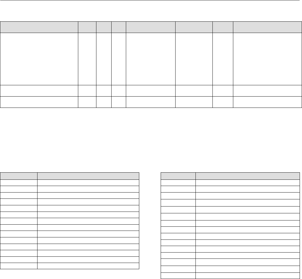
Instruction Manual
D103412X012
Detailed Setup—Transducer Block
January 2015
86
Table 4‐14. Transducer Block Parameter Definitions (Continued)
Description
Protect
Category
Initial ValueRangeMode
RO /
RW
Index
Number
Label
PARAMETER_NAME
Block Information
BLOCK_INFO 98 RO
Bit 0: Travel feedback
sensor detected
Bit 1: Output Block
Scheduled
Bit 2: Trigger Capturing
Bit 3: Output Block in
Normal Mode
Bit 4: Write Lock is on
Bit 5: Resource Block in
Auto Mode
Data Type: Bit String (2 bytes)
Reserved B
RESERVED_B 99 RW Data Type: Bit String (4 bytes)
Travel Always
TRAVEL_ALWAYS 100 RO Data Type: DS-65
View Lists
View lists allow the values of a set of parameters to be accessed at the same time. Views 1 and 2 contain operating
parameters and are defined by the Fieldbus Foundation. View 3 contains dynamic parameters and View 4 contains
static parameters with configuration and maintenance information. Views 3 and 4 are defined by the manufacturer.
Table 4‐15. Transducer Block, View 1
Index Number Parameter
1 ST_REV
5.1 MODE_BLK.TARGET
5.2 MODE_BLK.ACTUAL
5.3 MODE_BLK.PERMITTED
5.4 MODE_BLK.NORMAL
6 BLOCK_ERR
10 TRANSDUCER_TYPE
11 XD_ERROR
13.1 FINAL_VALUE.STATUS
13.2 FINAL_VALUE.VALUE
17.1 FINAL_POSITION_VALUE.STATUS
17.2 FINAL_POSITION_VALUE.VALUE
32.1 SETPOINT_D.STATUS
32.2 SETPOINT_D.VALUE
Table 4‐16. Transducer Block, View 2
Index Number Parameter
1 ST_REV
10 TRANSDUCER_TYPE
14.1 FINAL_VALUE_RANGE.EU_100
14.2 FINAL_VALUE_RANGE.EU_0
14.3 FINAL_VALUE_RANGE.UNITS_INDEX
14.4 FINAL_VALUE_RANGE.DECIMAL
15 FINAL_VALUE_CUTOFF_HI
16 FINAL_VALUE_CUTOFF_LO
18 SERVO_GAIN
19 SERVO_RESET
20 SERVO_RATE
21 ACT_FAIL_ACTION
40.1 GRANT_DENY.GRANT
40.2 GRANT_DENY.DENY
50 INPUT_CHAR

Instruction Manual
D103412X012
Detailed Setup—Transducer Block
January 2015
87
Note
Because individual views are limited in size, View Lists 3 and 4 have multiple parts.
Table 4‐17. Transducer Block, View 3.1
Index Number Parameter
1 ST_REV
5.1 MODE_BLOCK.TARGET
5.2 MODE_BLOCK.ACTUAL
5.3 MODE_BLOCK.PERMITTED
5.4 MODE_BLOCK.NORMAL
6 BLOCK_ERR
10 TRANSDUCER_TYPE
11 XD_ERROR
13.1 FINAL_VALUE.STATUS
13.2 FINAL_VALUE.VALUE
17.1 FINAL_POSITION_VALUE.STATUS
17.2 FINAL_POSITION_VALUE.VALUE
32.1 SETPOINT_D.STATUS
32.2 SETPOINT_D.VALUE
35.1 SUPPLY_PRESSURE.STATUS
35.2 SUPPLY_PRESSURE.VALUE
36.1 PRESSURE_A.STATUS
36.2 PRESSURE_A.VALUE
37.1 PRESSURE_B.STATUS
37.2 PRESSURE_B.VALUE
38.1 PRESSURE_DIFF.STATUS
38.2 PRESSURE_DIFF.VALUE
48 TEMPERATURE
49 TRAVEL_TARGET
52 TRAVEL_DEVIATION
53 DRIVE_SIGNAL
54 DRIVE_CURRENT
55 MLFB
59 FAILED_ACTIVE
60 MAINT_ACTIVE
61 ADVISE_ACTIVE
71 RECOMMEND_ACTION
72 TRAVEL_ACCUM
73 CYCLE_COUNT
75.1 INST_ALERTS_ENABLE.ELECT_ENABLE
75.2 INST_ALERTS_ENABLE.SENSOR_ENABLE
75.3 INST_ALERTS_ENABLE.ENVIRO_ENABLE
75.4 INST_ALERTS_ENABLE.TRAVEL_ENABLE
75.5 INST_ALERTS_ENABLE.PROX_ENABLE
75.6 INST_ALERTS_ENABLE.TVL_HISTORY_ENABLE
75.7 INST_ALERTS_ENABLE.PERF_ENABLE
Table 4‐18. Transducer Block, View 3.2
Index Number Parameter
1 ST_REV
74.1 INST_ALERTS_ACTIVE.ELECT_ACTIVE
74.2 INST_ALERTS_ACTIVE.SENSOR_ACTIVE
74.3 INST_ALERTS_ACTIVE.ENVIRO_ACTIVE
74.4 INST_ALERTS_ACTIVE.TRAVEL_ACTIVE
74.5 INST_ALERTS_ACTIVE.PROX_ACTIVE
74.6 INST_ALERTS_ACTIVE.TVL_HISTORY_ACTIVE
74.7 INST_ALERTS_ACTIVE.PERF_ACTIVE
74.8 INST_ALERTS_ACTIVE.PD_EVENT_ACTIVE
74.9 INST_ALERTS_ACTIVE.PD_DETAIL1_ACTIVE
74.10 INST_ALERTS_ACTIVE.PD_DETAIL2_ACTIVE
74.11 INST_ALERTS_ACTIVE.PD_DETAIL3_ACTIVE
74.12 INST_ALERTS_ACTIVE.PD_DETAIL4_ACTIVE
74.13 INST_ALERTS_ACTIVE.PD_DETAIL5_ACTIVE
78 SELFTEST_STATUS
79 HEALTH_INDEX
86.1 DEVICE_RECORD.TEMP_MAX
86.2 DEVICE_RECORD.TEMP_MAX_TIME
86.3 DEVICE_RECORD.TEMP_MIN
86.4 DEVICE_RECORD.TEMP_MIN_TIME
86.5 DEVICE_RECORD.SUPP_PRESS_MAX
86.6 DEVICE_RECORD.SUPP_PRESS_MAX_TIME
86.7 DEVICE_RECORD.SUPP_PRESS_MIN
86.8 DEVICE_RECORD.SUPP_PRESS_MIN_TIME
Table 4‐19. Transducer Block, View 4.1
Index Number Parameter
1 ST_REV
3 STRATEGY
4 ALERT_KEY
10 TRANSDUCER_TYPE
22 ACT_MAN_ID
23 ACT_MODEL_NUM
24 ACT_SN
25 VALVE_MAN_ID
26 VALVE_MODEL_NUM

Instruction Manual
D103412X012
Detailed Setup—Transducer Block
January 2015
88
Table 4‐20. Transducer Block, View 4.2
Index Number Parameter
1 ST_REV
27 VALVE_SN
28 VALVE_TYPE
29 XD_CAL_LOC
30 XD_CAL_DATE
31 XD_CAL_WHO
89 TEMPERATURE_UNITS
90 PRESSURE_UNITS
91 TVL_UNITS
92 LENGTH_UNITS
93 AREA_UNITS
94 SPRING_RATE_UNITS
Table 4‐21. Transducer Block, View 4.3
Index Number Parameter
1 ST_REV
39 PWA_SIMULATE
41.1 TVL_PRESS_CONTROL.TVL_PRESS_SELECT
41.2 TVL_PRESS_CONTROL.TVL_PRESS_STATE
42.1 BASIC_SETUP.ACTUATOR_STYLE
42.2 BASIC_SETUP.ZERO_PWR_COND
42.3 BASIC_SETUP.TRAVEL_SEN_MOTION
42.4 BASIC_SETUP.FEEDBACK_CONN
42.5 BASIC_SETUP.RELAY_TYPE
42.6 BASIC_SETUP.MAX_SUPP_PRESS
42.7 BASIC_SETUP.PRESS_RANGE_HI
42.8 BASIC_SETUP.PRESS_RANGE_LO
42.9 BASIC_SETUP.TVL_CAL_TRIGGER
42.10 BASIC_SETUP.TVL_TUNING_SET
42.11 BASIC_SETUP.PRESS_TUNING_SET
44.1 TRAVEL_TUNE.TVL_INTEG_ENABLE
44.2 TRAVEL_TUNE.TVL_INTEG_LIM_HI
44.3 TRAVEL_TUNE.TVL_INTEG_LIM_LO
44.4 TRAVEL_TUNE.TVL_INTEG_DEADZ
44.5 TRAVEL_TUNE.TVL_MLFB_GAIN
47.1 PRESS_TUNE.PRESS_CUTOFF_HI
47.2 PRESS_TUNE.PRESS_CUTOFF_LO
47.3 PRESS_TUNE.PRESS_PROP_GAIN
47.4 PRESS_TUNE.PRESS_INTEG_GAIN
47.5 PRESS_TUNE.PRESS_RATE_GAIN
47.6 PRESS_TUNE.PRESS_INTEG_DEADZ
47.7 PRESS_TUNE.PRESS_INTEG_HI_LIM
47.8 PRESS_TUNE.PRESS_INTEG_LO_LIM
47.9 PRESS_TUNE.PRESS_INTEG_IC_HI
47.10 PRESS_TUNE.PRESS_INTEG_IC_LO
47.11 PRESS_TUNE.PRESS_MLFB_GAIN
62 FAILED_ENABLE
63 MAINT_ENABLE
64 ADVISE_ENABLE
65 FAILED_MASK
66 MAINT_MASK
-continued-
Table 4‐21. Transducer Block, View 4.3 (continued)
Index Number Parameter
67 ADVISE_MASK
68 FAILED_PRI
69 MAINT_PRI
70 ADVISE_PRI
Table 4‐22. Transducer Block, View 4.4
Index Number Parameter
1 ST_REV
76.1 INST_ALERTS_CONFIG.SHUTDOWN_TRIGGER
76.2 INST_ALERTS_CONFIG.SHUTDOWN_RECOVERY
76.3 INST_ALERTS_CONFIG.OUTPUT_BLK_TIMEOUT
76.4 INST_ALERTS_CONFIG.DRIVE_CURRENT_ALRT_PT
76.5 INST_ALERTS_CONFIG.DRIVE_CURRENT_TIME
76.6 INST_ALERTS_CONFIG.TEMP_HI_ALRT_PT
76.7 INST_ALERTS_CONFIG.TEMP_LO_ALRT_PT
76.8 INST_ALERTS_CONFIG.SUP_PRES_HI_ALRT_PT
76.9 INST_ALERTS_CONFIG.SUP_PRES_LO_ALRT_PT
77.1 INST_ALERTS_CONFIG2.TVL_DEV_ALRT_PT
77.2 INST_ALERTS_CONFIG2.TVL_DEV_TIME
77.3 INST_ALERTS_CONFIG2.TVL_DEV_DB
77.4 INST_ALERTS_CONFIG2.TVL_ACCUM_ALRT_PT
77.5 INST_ALERTS_CONFIG2.TVL_ACCUM_DB
77.6 INST_ALERTS_CONFIG2.CYCLE_COUNT_ALRT_PT
77.7 INST_ALERTS_CONFIG2.CYCLE_COUNT_DB
77.8 INST_ALERTS_CONFIG2.TVL_OPEN_ALRT_PT
77.9 INST_ALERTS_CONFIG2.TVL_OPEN_DB
77.10 INST_ALERTS_CONFIG2.TVL_CLOSED_ALRT_PT
77.11 INST_ALERTS_CONFIG2.TVL_CLOSED_DB
77.12 INST_ALERTS_CONFIG2.TVL_LO_LO_ALRT_PT
77.13 INST_ALERTS_CONFIG2.TVL_LO_LO_DB
77.14 INST_ALERTS_CONFIG2.TVL_LO_ALRT_PT
77.15 INST_ALERTS_CONFIG2.TVL_LO_DB
77.16 INST_ALERTS_CONFIG2.TVL_HI_ALRT_PT
77.17 INST_ALERTS_CONFIG2.TVL_HI_DB
77.18 INST_ALERTS_CONFIG2.TVL_HI_HI_ALRT_PT
77.19 INST_ALERTS_CONFIG2.TVL_HI_HI_DB
82 UPGRADE_PROGRESS
87 PROTECTION
Table 4‐23. Transducer Block View, 4.5
Index Number Parameter
1 ST_REV
95.1 MAI_CHANNEL_1
95.2 MAI_CHANNEL_2
95.3 MAI_CHANNEL_3
95.4 MAI_CHANNEL_4
95.5 MAI_CHANNEL_5
95.6 MAI_CHANNEL_6
95.7 MAI_CHANNEL_7
95.8 MAI_CHANNEL_8
96 OUTBLOCK_SEL
97 PWA_SET_STATUS
Instruction Manual
D103412X012
Detailed Setup—AO Function Block
January 2015
89
Analog Output Function Block
Overview
The Analog Output (AO) function block (figure 4‐6) assigns an output value to a field device through a specified I/O
channel. The block supports mode control, signal status calculation, and simulation. Figure 4‐7 illustrates the internal
components of the AO function block, and table 4‐25 lists the definitions of the block parameters. The digital valve
controller measures and uses actual valve position for READBACK [16].
Figure 4‐6. Analog Output (AO) Function Block
B2716‐1
BKCALOUT
OUT
CAS IN
CAS IN = The remote setpoint value from another
function block.
BKCAL OUT = The value and status required by the
BKCAL IN input of another block to prevent reset
windup and to provide bumpless transfer to closed
loop control.
OUT = The block output and status.
READBACK = Actual valve position.
AO
READBACK
Note
The AO block actual mode will not move to Auto unless:
Resource Block actual mode is Auto, and
AO SHED_OPT [27] is set to a non‐zero value.
Note
Actual Block Mode (MODE_BLK.ACTUAL [5.2]) will remain out of service and the block cannot be scheduled if the block has not
been licensed. Contact your Emerson Process Management sales office to upgrade product licensing.
Note
Actual Block Mode (MODE_BLK.ACTUAL [5.2]) will remain in IMAN and the block Readback status will be Bad - Not Connected if
the Output Block Selection is set incorrectly. From the transducer block method Outblock Selection, select the desired output
block, see page 45.
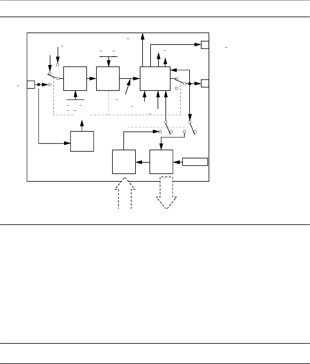
Instruction Manual
D103412X012
Detailed Setup—AO Function Block
January 2015
90
Figure 4‐7. Analog Output Function Block Schematic
B2717
CAS IN
Position
Feedback
Analog
Output
Access
Analog
Output
Access
Analog
Input
Shed
Mode
SP
HI/LO
Limit
SP
Rate
Limit
Convert
and Status
Calculation
BKCAL OUT
OUT
RCAS OUT
RCAS IN
SP RATE DN
SP RATE UP
SP WRK
PV SCALE
IO OPTS
Operator
Setpoint
READ BACK
PV
SP LOW LIM
SP HI LIM
CHANNEL
MODE
Modes
The Analog Output function block supports the following modes:
Manual (Man)—You can manually set the output to the I/O channel through the OUT [9] attribute. This mode is used
primarily for maintenance, calibration and diagnostics.
Automatic (Auto)—The block output (OUT [9]) reflects the target operating point specified by the setpoint (SP [8])
attribute. Typically the setpoint is set by the user.
Cascade (Cas)—The SP [8] attribute is set by another function block through a connection to CAS_IN [17]. The SP [8]
value is used to set the OUT [9] attribute automatically. This is the most frequently used mode in the digital valve
controller.
Note
The transducer block must be in Auto for the mode to go to AUTO, CAS, MAN, or RCAS.
RemoteCascade (RCas)—The SP [8] is set by a host computer by writing to the RCAS_IN [28] parameter. The SP [8]
value is used to set the OUT [9] attribute automatically.

Instruction Manual
D103412X012
Detailed Setup—AO Function Block
January 2015
91
Out of Service (OOS)—The block is not processed. The output channel is maintained at the last value and the status
of OUT [9] is set to Bad: Out of Service. The BLOCK_ERR [6] attribute shows Out of Service.
Initialization Manual (Iman)—The path to the output hardware is broken and the AO block output will remain at the
last position. This means the transducer block mode is Out of Service or Manual or configured to respond to the DO
block.
Local Override (LO)—The output of the block is not responding to inputs because the fault state action is active. OUT
[9] freezes or goes to value per IO_OPTS [14].
The target mode of the block may be restricted to one or more of the following modes: Man, Auto, Cas, RCas, or OOS.
Mode Handling
Shed Options—RCAS Mode Only
Automatically changing through the permitted modes when starting from a remote mode, fall from (or shed) or climb
to a remote mode is determined by the parameter SHED_OPT [27]. A block climbs and sheds through the same path.
For example, if SHED_OPT [27] specifies that a block should shed to Auto, then, if the block target mode is set to RCas,
the block goes through Auto on the way to RCas.
When the block is in Cas mode and the CAS_IN [17] input goes bad, the block sheds mode to the next lower permitted
mode.
You can configure the shed option as follows:
Shed With Return Options
Remote cascade connection failure shifts actual mode but keeps trying to restore remote cascade (in other words, the
remote cascade target mode stays in effect).
Note
During Shed with Return Options, the actual mode is changed, while the target mode stays the same.
Normal—On failure of a remote cascade connection the block attempts to attain the highest permitted non‐remote
mode until remote cascade is restored. Cas is the highest permitted non‐remote mode and Auto is is the next
permitted non‐remote mode. If Cas or Auto are not available, the block will shed by default to Man.
Retained Target—The retained target mode is the previous target mode before it was changed to RCAS or ROUT. On
failure of a remote cascade connection the block attempts to attain the retained target mode.
Auto—On failure of a remote cascade connection the block attempts to attain Auto, if permitted, until remote cascade
is restored.
Man—On failure of a remote cascade connection the block sheds to Man until a remote cascade connection is
restored.
Shed With No Return Options
Note
During Shed with No Return Options, the target mode is changed, while the actual mode stays the same.

Instruction Manual
D103412X012
Detailed Setup—AO Function Block
January 2015
92
For any shed with no return option, the target mode changes as determined by the option. Therefore, there is no
attempt to restore the connection following failure. The behavior on change to the remote cascade target mode is
identical to that for Shed With Return Options.
Normal—On failure of a remote cascade connection the block sets the target mode to the highest permitted
non‐remote mode. Cas is the highest permitted non‐remote mode and Auto is is the next highest permitted
non‐remote mode. If Cas or Auto are not available, the block will shed by default to Man.
Retained Target—The retained target mode is the previous target mode before it was changed to RCAS or ROUT. On
failure of a remote cascade connection the block sets the target mode to the retained target mode.
Auto—On failure of a remote cascade connection, the block sets the target mode to Auto, if permitted.
Man—On failure of remote cascade connection, the block sets the target mode to Man, if permitted.
The user may configure SHED_OPT [27] so that it calls for a target mode that is not permitted. When doing this, the
mode logic uses the following rules as applied by the remote logic:
Shed logic never results in a non‐permitted target mode.
Shed logic never attempts to attain an actual mode of Auto or Cas if that mode is not permitted.
Status Handling
Output or readback fault detection is reflected in the status of PV [7], OUT [9], and BKCAL_OUT [25]. A limited SP [8]
condition is reflected in the BKCAL_OUT [25] status. When simulation is enabled through the SIMULATE [10] attribute,
you can set the value and status for PV [7] and READBACK [16].
When the block is in Cas mode and the CAS_IN [17] input goes bad, the block sheds mode to the next permitted
mode.
Setting the Output
To set the output for the AO block, you must first set the mode to define the manner in which the block determines its
setpoint. In Manual mode the value of the output attribute (OUT [9]) must be set manually by the user, and is
independent of the setpoint. In Automatic mode, OUT [9] is set automatically based on the value specified by the set
point (SP [8]) in engineering units and the I/O Options attribute. In addition, you can limit the SP [8] value and the rate
at which a change in the SP [8] is passed to OUT [9].
In Cascade mode, the cascade input connection (CAS_IN [17]) is used to update the SP [8]. The back calculation
output (BKCAL_OUT [25]) is wired to the back calculation input (BKCAL_IN [27]) of the upstream block that provides
CAS_IN [17]. This provides bumpless transfer on mode changes and windup protection in the upstream block.
Note
You must wire BKCAL_OUT [25] to BKCAL_IN [27] of the upstream block that provides CAS_IN [17]. Otherwise, the AO will not
initialize properly, and the setpoint at CAS_IN [17] will not be passed to OUT [9].
An analog readback value, such as valve position, is shown by the process value (PV [7]) attribute in engineering units.
To support testing, you can enable simulation, which allows you to manually set the channel feedback. There is no
alarm detection in the AO function block.

Instruction Manual
D103412X012
Detailed Setup—AO Function Block
January 2015
93
To select the manner of processing the SP and the channel output value configure the setpoint limiting options, the
tracking options, and the conversion and status calculations.
Output Block PV Status
The Output Block PV Status is determined by the value of the PlantWeb Alerts Set PV Status parameter in the
transducer block (PWA_SET_STATUS [97]), the Transducer Block mode, and enabled Active PlantWeb alarms. Refer to
table 4‐11.
Set Point Selection and Limiting
To select the source of the SP [8] value use the MODE [5] attribute. In Automatic (Auto) mode, the local,
manually‐entered SP [8] is used. In Cascade (Cas) mode, the SP [8] comes from another block through the CAS_IN [17]
input connector. In RemoteCascade (RCas) mode, the SP [8] comes from a host computer that writes to RCAS_IN [28].
The range and units of the SP [8] are defined by the PV_SCALE [11] attribute.
In Manual (Man) mode the SP [8] automatically tracks the PV [7] value when you select the SP‐PV Track in Man I/O
option in IO_OPTS [14]. This option can be used to minimize valve movement when the AO block is transitioned from
Manual mode to Auto. You can disable this option in OOS mode only.
The SP [8] value is limited to the range defined by the setpoint high limit attribute (SP_HI_LIM [20]) and the setpoint
low limit attribute (SP_LO_LIM [21]).
In Auto mode, the rate at which a change in the SP [8] is passed to OUT [9] is limited by the values of the setpoint
upward rate limit attribute (SP_RATE_UP [19]) and the setpoint downward rate limit attribute (SP_RATE_DN [18]). A
limit of zero disables rate limiting.
As shown in figure 4‐8, the block executes a percentage of the set point change each macrocycle. For example, if the
set point rate is set at 10% per second and the macrocycle is 500 milliseconds (0.5 seconds or 50% of 1 second), then
during the first macrocycle the set point will change 5% (50% of the 10% per second rate). If the macrocycle is 750
milliseconds (0.75 seconds or 75% of 1 second), then during the first macrocycle the setpoint will change 7.5% (75% of
10).
When the transducer block receives the setpoint change from an AO block with rate limits, it will smoothly move the
valve to the requested setpoint at the rate limit configured in the AO block.
In Auto mode, the converted SP [8] value is stored in the OUT [9] attribute. In Man mode, the OUT [9] attribute is set
manually, and is used to set the analog output defined by the CHANNEL [22] parameter.
You can access the actuator position associated with the output channel through the READBACK [16] parameter (in
OUT units) and in the PV [7] attribute (in engineering units). The digital valve controller supports position feedback
and therefore provides the actual valve position in PV [7] and READBACK [16] directly.
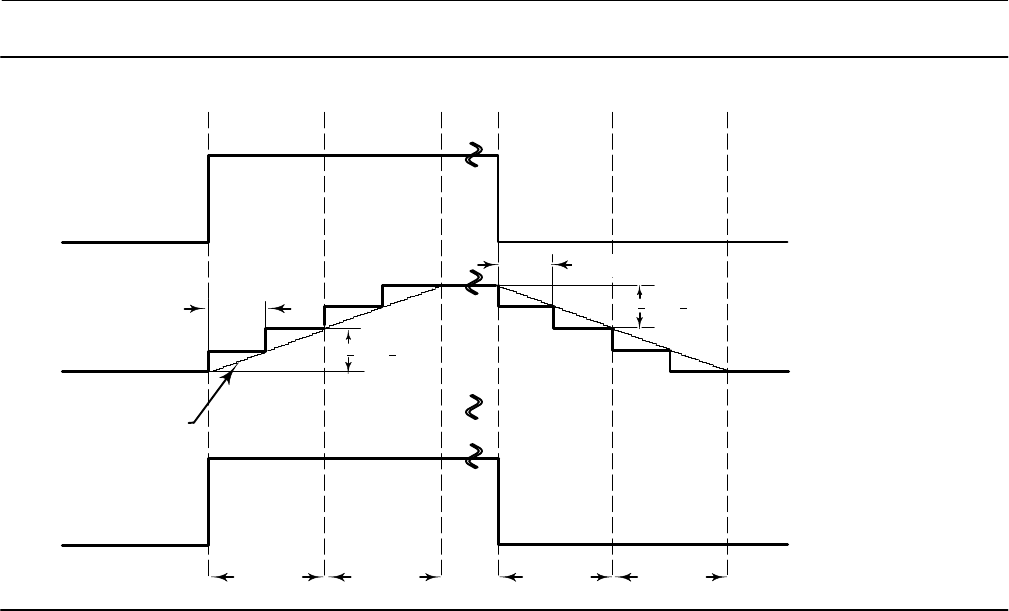
Instruction Manual
D103412X012
Detailed Setup—AO Function Block
January 2015
94
Figure 4‐8. Analog Output Function Block Timing Diagram
B2718‐1
CAS_IN, 2
OUT
SP
Time
SP RATE UP
SP RATE DN
1 second 1 second 1 second 1 second
1 macrocycle
1 macrocycle
TRANSDUCER BLOCK
TRAVEL TARGET
Action On Fault Detection
To define the action you wish the valve to take when the block is in CAS mode, and the CAS_IN [17] input detects a
communication failure, or is commanded to go to fault state by the upstream block or the resource block, configure
the following parameters:
IO_OPTS [14]: Determines the action OUT [9] will take upon a fault state. If the IO_OPTS [14] “Fault State to Value” is
not selected, then OUT [9] holds its last position when Fault State is set. If “Fault State to Value” is selected, OUT [9]
goes to the FSTATE_VAL [24] value when Fault State is set.
FSTATE_TIME [23]: The length of time, in seconds, that the AO block will wait to set Fault State. When Fault State is
set, the OUT [9] value goes to either the FSTATE_VAL [24] value or holds its last position, depending on I/O_OPTS [14].
When the block has a target mode of CAS, a fault condition will be detected if the CAS_IN [17] has a BAD status or an
Initiate Fault State substatus is received from the upstream block.
FSTATE_VAL [24]: Determines the OUT [9] value if IO_OPTS “Fault State to Value” is selected. The OUT [9] value
transitions to FSTATE_VAL [24] after FSTATE_TIME [23] elapses and the fault condition has not cleared.
I/O Options
The I/O options parameter (IO_OPTS [14]) allows you to select how the I/O signals are processed. You can set I/O
options in Out of Service mode only. The following I/O options are available in the AO block:
Use PV for BKCAL_OUT—Changes the BKCAL_OUT [25] value to the PV [7] value. When the Use PV for BKCAL_OUT
option is not enabled (False), the BKCAL_OUT [25] value is the working setpoint value.
Target to Man if Fault State Activated—Set the target mode to Man, thus losing the original target, if Fault State is
activated. This latches an output block into the manual mode.

Instruction Manual
D103412X012
Detailed Setup—AO Function Block
January 2015
95
Use Fault State value on Restart—Use the value of FSTATE_VAL [24] for SP [8] when power is restored or if the device is
restarted, otherwise use the last value saved in non‐volatile memory. This does not act like Fault State, it only uses the
value of FSTATE_VAL [24].
Fault State to Value—The output action to take when a fault occurs (if not selected, use hold last value; if selected, use
FSTATE_VAL [24]).
Increase to Close—If the Increase to Close bit is set the value to the transducer is inverted, e.g. 20% becomes 80%.
SP-PV Track in Man—Permits the setpoint to track the process variable when the target mode of the block is MAN.
SP-PV Track in LO or IMan—Permits the setpoint to track the process variable when the actual mode of the block is LO
or IMan.
SP Track retained Target—Permits the setpoint to track the RCas or Cas parameter based on the retained target mode
when the actual mode of the block is LO or Man. When SP‐PV track options are enabled, the SP Track retained target
will have precedence in the selection of the value to track when the actual mode is Man and LO.
Simulation
When simulate is active, the transducer sub‐parameters show the actual transducer block status and value as normally
passed back to the AO block. The Simulate sub‐parameters are writable and replace actual transducer values.
Note
When simulate is active, the output block no longer writes values to the transducer block. If the Output Blk Timeout period is
exceeded, the transducer block may move the valve to the Zero Power Condition depending on the configuration of the Output
Block Timeout Alert.
Application Information
The configuration of an AO function block and its associated output channels depends on the specific application. A
typical configuration for the Analog Output involves the following attributes:
PV_SCALE Set the range and engineering units to values that correspond to the operation range.
For the digital valve controller, PV_SCALE [11] is typically set between 0 and 100%.
BKCAL_OUT If you are using the CAS_IN [17] connector wired from another block, wire the
BKCAL_OUT [25] attribute to the other block's BKCAL_IN [27] attribute.
IO_OPTS Set the type of tracking and action upon fault state.
SHED_OPT Set the action to be taken when the set point or output are not updated in a remote
mode.
Block Errors
Table 4‐24 lists conditions reported in the BLOCK_ERR [6] parameter. Conditions in italics are not applicable for the AO
block and are provided only for your reference.

Instruction Manual
D103412X012
Detailed Setup—AO Function Block
January 2015
96
Table 4‐24. BLOCK_ERR Conditions
Condition Number Condition Name and Description
0Other (N/A)
1Block Configuration Error ‐ CHANNEL and SHED_OPT set to 0
2Link Configuration Error (N/A)
3Simulate active ‐ Simulation is enabled and the block is using a simulated value in its execution.
4Local Override ‐ Device in fault state. Actual mode LO.
5Device Fault State Set ‐ AO block in fault state after FSTATE_TIME because of Bad status or IFS substatus on CAS_IN or
Resource block commanded fault state.
6Device Needs Maintenance Soon ‐ Indicates a Maintenance PlantWeb Alert condition is active if Block Error Reporting is
enabled. See page 62.
7Input failure/process variable has Bad status (N/A)
8Output failure ‐ PV has bad status.
9Memory Failure (N/A)
10 Lost Static Data (N/A)
11 Lost NV Data (N/A)
12 Readback Check Failed (N/A)
13 Device Needs Maintenance Now ‐ Indicates Failed PlantWeb Alert condition is active if Block Error Reporting is enabled. See
page 62.
14 Power Up ‐ This condition exists after power up until actual mode is not Out of Service.
15 Out of Service ‐ The block is in Out of Service (OOS) mode.
AO Function Block Parameter List (table 4‐25)
Read/Write Capability: RO - Read Only, RW - Read Write
Mode: The block mode(s) required to write to the parameter
Double indentation and shaded Index Number indicates sub‐parameter
Table 4‐25. Analog Output Function Block Parameter Definitions
Label
PARAMETER_NAME
Index
Number
RO /
RW
Block
Mode Range Initial
Value Description
Static Revision
ST_REV 1 RO N/A 0 to 65535 0
Data Type: Unsigned16
The revision level of the static data associated with
the function block. The revision value will be
incremented each time a static parameter value in
the block is changed.
Tag Description
TAG_DESC 2 RW ALL 7 bit ASCII Spaces
Data Type: Octet String
The user description of the intended application of
the block.
Strategy
STRATEGY 3 RW ALL 0 to 65535 0
Data Type: Unsigned16
The strategy field can be used to identify grouping
of blocks. This data is not checked or processed by
the block.
Alert Key
ALERT_KEY 4 RW ALL 1 to 255 0
Data Type: Unsigned8
The identification number of the plant unit. This
information may be used in the host for sorting
alarms, etc.
-Continued-

Instruction Manual
D103412X012
Detailed Setup—AO Function Block
January 2015
97
Table 4‐25. Analog Output Function Block Parameter Definitions (Continued)
Description
Initial
Value
Range
Block
Mode
RO /
RW
Index
Number
Label
PARAMETER_NAME
Block Mode
MODE_BLK 5
Data Type: DS‐69
Valid Bits: 7: OOS, 6: IMAN, 5: LO, 4: MAN, 3: AUTO,
2: CAS, 1: RCAS
The actual, target, permitted, and normal modes of
the block.
Target: The requested block mode
Actual: The current mode of the block
(Note: Bit 6 (IMAN) is valid for ACTUAL only)
Permitted: Allowed modes for Target
Normal: Most common mode for Target
TARGET 5.1 RW ALL
OOS
MAN
AUTO
AUTO‐CAS
AUTO‐RCAS
OOS until
block is
configured,
then last valid
target
ACTUAL
5.2 RO ALL OOS
PERMITTED
5.3 RW ALL OOS+MAN+AUTO+
CAS+RCAS
OOS+MAN+A
UTO+
CAS+RCAS
NORMAL
5.4 RW ALL AUTO
Block Error
BLOCK_ERR 6 RO N/A
1: Block Configuration
Error
3: Simulate Active
4: Local Override
5: Device Fault State Set
8: Output Failure
14: Power‐up
15: Out‐of‐Service
Dynamic
Data Type: Bit String (2 byte)
0=inactive
1=active
This parameter reflects the error status associated
with the hardware or software components
associated with a block. It is a bit string, so that
multiple errors may be shown. See table 4‐24.
Process Variable
PV 7 RO N/A PV Status set equal to
READBACK status Dynamic
Data Type: DS‐65
The process variable used in block execution. This
value is converted from READBACK to show the
actuator position in the same units as the setpoint
value.
Set Point
SP 8
OOS
MAN
AUTO
PV_SCALE +/- 10% Dynamic
Data Type: DS‐65
The SP of the analog block. Can be derived from
CAS_IN, RCAS_IN in normal modes, or can track PV
in MAN, IMan or LO modes. IO_OPTS is used to
determine value of SP in MAN, IMan or LO. If no
IO_OPTS for SP tracking are set, SP will freeze when
mode changes from CAS or RCAS.
Output
OUT 9MAN
OOS OUT_SCALE +/- 10% Dynamic
Data Type: DS‐65
The primary value and status calculated by the
block in Auto mode. OUT may be set manually in
Man mode.
Simulate
SIMULATE 10
Data Type: DS‐82
Allows the analog input to be manually supplied
when simulate is enabled. When simulation is
disabled, the simulate value and status track actual
value & status.
SIMULATE_STATUS 10.1 RW ALL 0
SIMULATE_VALUE 10.2 RW ALL 0
TRANSDUCER_STATUS 10.3 RO ALL 0
TRANSDUCER_VALUE 10.4 RO ALL 0
ENABLE/DISABLE 10.5 RW ALL
0: Not Initialized
1: Simulation Disable
2: Simulation Active
1: Simulation
Disabled
Process Value Scale
PV_SCALE 11 RW OOS
EU at 100%
EU at 0%
Units index
Decimal Point
100
0
%
2
Data Type: DS‐68
The high and low scale values, engineering units
code, and number of decimal places to be used in
displaying the PV parameter and parameters which
have the same scaling as PV.
Transducer Scale
XD_SCALE 12 RO OOS
EU at 100%
EU at 0%
Units index
Decimal Point
100 only
0 only
% only
2
Data Type: DS‐68
The high and low scale values and engineering
units code are read only. This parameter
determines the number of digits to the right of the
decimal point used with the value obtained from
the transducer for a specified channel.
-Continued-

Instruction Manual
D103412X012
Detailed Setup—AO Function Block
January 2015
98
Table 4‐25. Analog Output Function Block Parameter Definitions (Continued)
Description
Initial
Value
Range
Block
Mode
RO /
RW
Index
Number
Label
PARAMETER_NAME
Grant Deny
GRANT_DENY 13 Data Type: DS‐70
Options for controlling access of host computers
and local control panels to operating, tuning, and
alarm parameters of the block.
GRANT: 1 = granted, 0= N/A
DENY: 1 = denied, 0 = N/A
GRANT 13.1 RW ALL 0: Program
1: Tune
2: Alarm
3: Local
All bits: 0
DENY 13.2 RW ALL All bits: 0
I/O Options
IO_OPTS 14 OOS
1: SP tracks PV in Man
3: SP tracks PV in LO or
Iman
4: SP Track retained
target in Man or LO
5: Increase to Close
6: Fault State to value
0=freeze
1=go to Fault State
value
7: Use Fault State
value on restart
8: Target to Man if
Fault State activated
9: Use PV for
BKCAL_OUT
0=SP
1=PV
All bits: 0
Data Type: Bit String (2 byte)
0=disable
1=enable
Allows you to select the type of tracking and the
output value when a fault condition occurs.
Status Options
STATUS_OPTS 15 OOS 4: Propagate Failure
Backward All bits: 0
Data Type: Bit String
0=disable
1=enable
Options the user may select for the block
processing of status.
Readback
READBACK 16 RO N/A
Status
Data Type: DS‐65
Readback is the de‐characterized valve position as
reported by the transducer block parameter
FINAL_POSITION_VALUE [17]. This correlates with
the AO block parameter OUT [9], which is the
setpoint to the transducer. READBACK is the
simulated input if SIMULATE is enabled or the
transducer block feedback if SIMULATE is disabled.
Value Dynamic
Cascade Input
CAS_IN 17 ALL Status
BAD:
NC:
const Data Type: DS‐65
The setpoint value from another function block.
Value 0
Setpoint Rate Down
SP_RATE_DN 18 ALL Positive, 0 disables
rate limiting PV units +INF
Data Type: Float
Ramp rate for downward set point changes. When
the ramp rate is set to zero, the set point is used
immediately.
Setpoint Rate Up
SP_RATE_UP 19 ALL Positive, 0 disables
rate limiting PV units +INF
Data Type: Float
Ramp rate for upward set point changes. When the
ramp rate is set to zero, the setpoint is used
immediately.
Setpoint High Limit
SP_HI_LIM 20 ALL PV Scale +/- 10% 100
Data Type: Float
The highest set point value allowed. SP_HI_LIM
must be greater than SP_LO_LIM.
Setpoint Low Limit
SP_LO_LIM 21 ALL PV Scale +/- 10% 0
Data Type: Float
The lowest set point value allowed. SP_LO_LIM
must be less than SP_HI_LIM.
AO Channel
CHANNEL 22 OOS 1=Setpoint 1=Setpoint
Data Type: Unsigned16
Defines which transducer parameter receives the
AO output. Select Setpoint to control valve
position.
Fault State Time
FSTATE_TIME 23 ALL Positive, seconds 0
Data Type: Float
Time from failure detection to reaction if failure still
exists.
-Continued-

Instruction Manual
D103412X012
Detailed Setup—AO Function Block
January 2015
99
Table 4‐25. Analog Output Function Block Parameter Definitions (Continued)
Description
Initial
Value
Range
Block
Mode
RO /
RW
Index
Number
Label
PARAMETER_NAME
Fault State Value
FSTATE_VAL 24 ALL PV Scale +/- 10% 0
Data Type: Float
Preset value to use if I/O_OPTS Fault State to Value
or Use Fault State Value on Restart is set.
Back Calculation Output
BKCAL_OUT 25 RO N/A
Status Limits
Dynamic
Data Type: DS‐65 The value and
status required by the BKCAL_IN input of another
block to prevent reset windup and to provide
bumpless transfer to closed loop control.
Value
Remote Cascade Input
RCAS_IN 26 ALL Status
BAD: NoCom:
NoVal:
const Data Type: DS‐65
Target SP and status by supervisory host
Value 0 Trk
Shed Options
SHED_OPT 27 ALL
Defined by FF spec
0=Invalid
1=Normal Shed,
Normal Return
2=Normal Shed, No
Return
3=Shed to Auto,
normal return
4=Shed to Auto, no
return. Target mode
changes to Auto on
detection of a shed
condition
5=Shed to Manual,
normal return
6=Shed to Manual, No
return. Target mode
changes to MAN on
detection of a shed
condition.
7=Shed to retained
target, normal return
8=Shed to retained
target, no return.
(Change target to
retained target)
0
Data Type: Unsigned8
Defines the action to be taken when the set point is
not updated in a remote mode.
Remote Cascade Output
RCAS_OUT 28 RO N/A Status Dynamic Data Type: DS‐65
Block set point and status after ramping
Value
Update Event
UPDATE_EVT 29
Data Type: DS‐73
This alert is generated by any changes to static data.
UNACKNOWLEDGED 29.1 RW N/A
0:Undefined
1:Acknowledged
2:Unacknowledged
0: Undefined
UPDATE_STATUS 29.2 RO N/A
0:Undefined
1:Update reported
2:Update not reported
0: Undefined
TIME_STAMP 29.3 RO N/A 0
STATIC_REVISION 29.4 RO N/A 0
RELATIVE_INDEX 29.5 RO N/A 0
Block Alarm
BLOCK_ALM 30
Data Type: DS‐72
The block alarm is used for all configuration,
hardware, connection failure, or system problems
in the block.
UNACKNOWLEDGED 30.1 RW N/A
0:Undefined
1:Acknowledged
2:Unacknowledged
0: Undefined
ALARM_STATE 30.2 RO N/A
0:Undefined
1:Clear reported
2:Clear not reported
3:Active reported
4:Active not reported
0: Undefined
TIME_STAMP 30.3 RO N/A 0
SUBCODE 30.4 RO N/A 0
VALUE 30.5 RO N/A 0
-Continued-
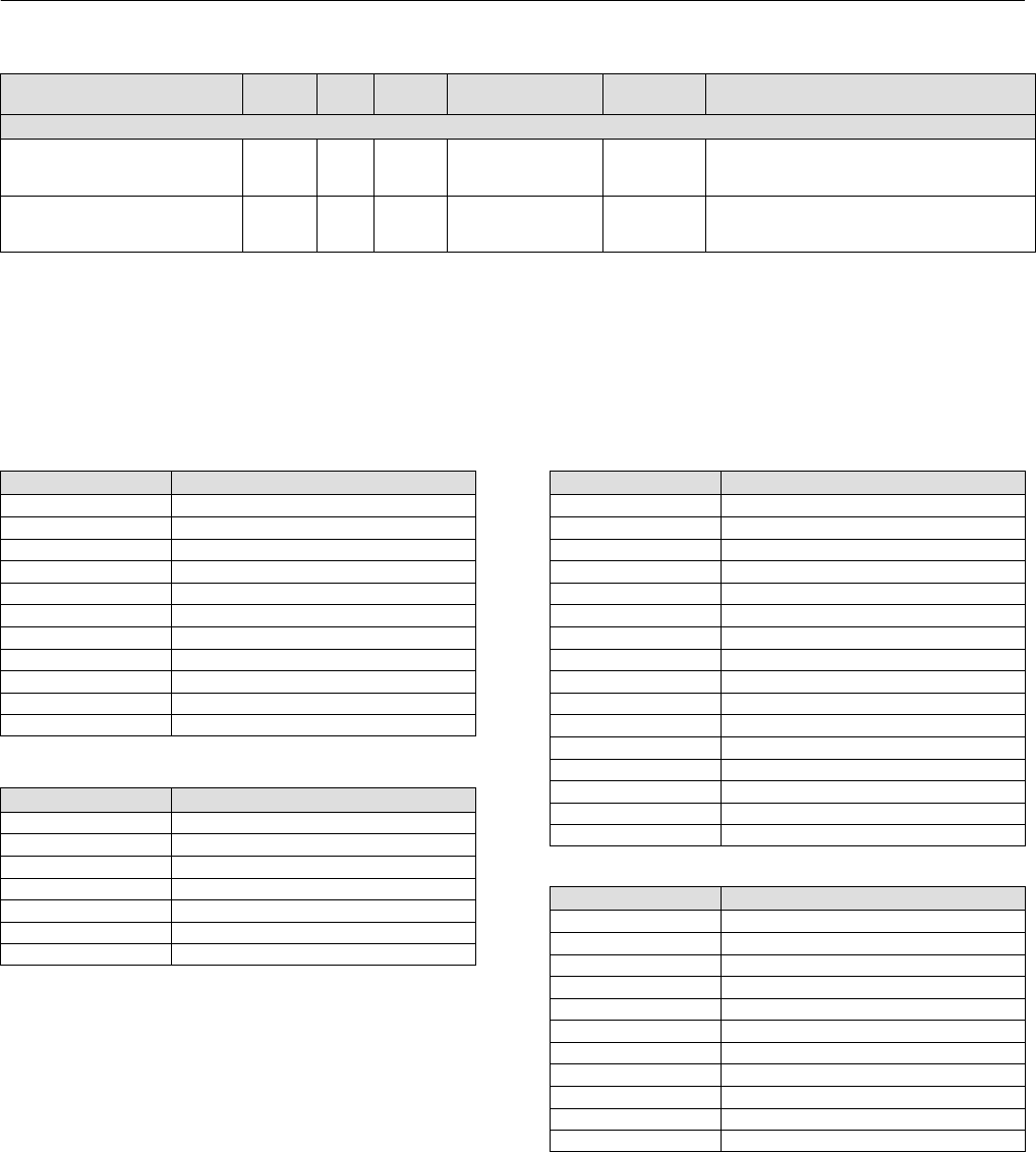
Instruction Manual
D103412X012
Detailed Setup—AO Function Block
January 2015
100
Table 4‐25. Analog Output Function Block Parameter Definitions (Continued)
Description
Initial
Value
Range
Block
Mode
RO /
RW
Index
Number
Label
PARAMETER_NAME
Extended Parameters
StdDev
STDDEV 31 RO N/A positive float Dynamic
Data Type: Float
Standard Deviation. To support DeltaV Variability
measurement.
Cap StdDev
CAP_STDDEV 32 RO N/A positive float Dynamic
Data Type: Float
Capability Standard Deviation. To support DeltaV
Variability measurement.
View Lists
View lists allow the values of a set of parameters to be accessed at the same time. Views 1 and 2 contain operating
parameters and are defined by the Fieldbus Foundation. View 3 contains dynamic parameters and View 4 contains
static parameters with configuration and maintenance information. Views 3 and 4 are defined by the manufacturer.
Table 4‐26. AO Function Block, View 1
Index Number Parameter
1 ST_REV
5.1 MODE_BLK.TARGET_MODE
5.2 MODE_BLK.ACTUAL_MODE
5.3 MODE_BLK.PERMITTED_MODE
5.4 MODE_BLK.NORMAL_MODE
6 BLOCK_ERR
7 PV
8 SP
9 OUT
16 READBACK
17 CAS_IN
Table 4‐27. AO Function Block, View 2
Index Number Parameter
1 ST_REV
11 PV_SCALE
12 XD_SCALE
13.1 GRANT_DENY.GRANT
13.2 GRANT_DENY.DENY
20 SP_HI_LIM
21 SP_LO_LIM
Table 4‐28. AO Function Block, View 3
Index Number Parameter
1 ST_REV
5.1 MODE_BLK.TARGET_MODE
5.2 MODE_BLK.ACTUAL_MODE
5.3 MODE_BLK.PERMITTED_MODE
5.4 MODE_BLK.NORMAL_MODE
6 BLOCK_ERR
7 PV
8 SP
9 OUT
16 READBACK
17 CAS_IN
25 BKCAL_OUT
26 RCAS_IN
28 RCAS_OUT
31 STDDEV
32 CAP_STDDEV
Table 4‐29. AO Function Block, View 4
Index Number Parameter
1 ST_REV
3 STRATEGY
4 ALERT_KEY
14 IO_OPTS
15 STATUS_OPTS
18 SP_RATE_DN
19 SP_RATE_UP
22 CHANNEL
23 FSTATE_TIME
24 FSTATE_VAL
27 SHED_OPT

Instruction Manual
D103412X012
Detailed Setup—AO Function Block
January 2015
101
Field Communicator Menu Structure
ANALOG OUTPUT FUNCTION BLOCK
Quick Config
Alert Key
Process Value Scale: EU at 100%
Process Value Scale: EU at 0%
Process Value Scale: Units Index
Process Value Scale: Decimal
Simulate: Simulate Status
Simulate: Simulate Value
Simulate: Transducer Status
Simulate: Transducer Value
Simulate: Simulate En/Disable
Setpoint: Status
Setpoint: Value
Setpoint High Limit
Setpoint Low Limit
Common Config
Alert Key
I/O Options
Block Mode: Target
Block Mode: Actual
Block Mode: Permitted
Block Mode: Normal
Process Value Scale: EU at 100%
Process Value Scale: EU at 0%
Process Value Scale: Units Index
Process Value Scale: Decimal
Setpoint: Status
Setpoint: Value
Setpoint High Limit
Setpoint Low Limit
Advanced Config
Fault State Time
Fault State Value
Shed Options
Simulate: Simulate Status
Simulate: Simulate Value
Simulate: Transducer Status
Simulate: Transducer Value
Simulate: Simulate En/Disable
Setpoint Rate Down
Setpoint Rate Up
Static Revision
Status Options
Strategy
Transducer Scale: EU at 100%
Transducer Scale: EU at 0%
Transducer Scale: Units Index
Transducer Scale: Decimal
I/O Reference
AO Channel
Online
Back Calculation Output: Status
Back Calculation Output: Value
Block Error
Cascade Input: Status
Cascade Input: Value
Block Mode: Target
Block Mode: Actual
Block Mode: Permitted
Block Mode: Normal
Output: Status
Output: Value
Process Value: Status
Process Value: Value
Remote Cascade Input: Status
Remote Cascade Input: Value
Remote Cascade Output: Status
Remote Cascade Output: Value
Readback: Status
Readback: Value
Setpoint: Status
Setpoint: Value
Status
Block Error
All
Characteristics
Static Revision
Tag Description
Strategy
Alert Key
Block Mode: Target
Block Mode: Actual
Block Mode: Permitted
Block Mode: Normal
Block Error
Process Value: Status
Process Value: Value
Setpoint: Status
Setpoint: Value
Output: Status
Output: Value
Simulate: Simulate Status
Simulate: Simulate Value
Simulate: Transducer Status
Simulate: Transducer Value
Simulate: Simulate En/Disable
Process Value Scale: EU at 100%
Process Value Scale: EU at 0%
Process Value Scale: Units Index
Process Value Scale: Decimal
Transducer Scale: EU at 100%
Transducer Scale: EU at 0%
Transducer Scale: Units Index
Transducer Scale: Decimal
Grant Deny: Grant
Grant Deny: Deny
I/O Options
Status Options
Readback: Status
Readback: Value
Cascade Input: Status
Cascade Input: Value
Setpoint Rate Down
Setpoint Rate Up
Setpoint High Limit
Setpoint Low Limit
AO Channel
Fault State Time
Fault State Value
Back Calculation Output: Status
Back Calculation Output: Value
Remote Cascade Input: Status
Remote Cascade Input: Value
Shed Options
Remote Cascade Output: Status
Remote Cascade Output: Value
Update Event: Unacknowledged
Update Event: Update State
Update Event: Time Stamp
Update Event: Static Rev
Update Event: Relative Index
Block Alarm: Unacknowledged
Block Alarm: Alarm State
Block Alarm: Time Stamp
Block Alarm: Subcode
Block Alarm: Value
StdDev
Cap StdDev
Connectors
Back Calculation Output: Status
Back Calculation Output: Value
Cascade Input: Status
Cascade Input: Value
Output: Status
Output: Value
Other
Tag Description
Grant Deny: Grant
Grant Deny: Deny
Update Event: Unacknowledged
Update Event: Update State
Update Event: Time Stamp
Update Event: Static Rev
Update Event: Relative Index
Block Alarm: Unacknowledged
Block Alarm: Alarm State
Block Alarm: Time Stamp
Block Alarm: Subcode
Block Alarm: Value
StdDev
Cap StdDev

Instruction Manual
D103412X012
Detailed Setup—PID Function Block
January 2015
102
PID Function Block
Overview
The PID function block (figure 4‐9) combines all of the necessary logic to perform proportional/integral/derivative
(PID) control. The block supports mode control, signal scaling and limiting, feedforward control, override tracking,
alarm limit detection, and signal status propagation.
Figure 4‐9. Proportional+Integral+Derivative (PID) Function Block
B2720
BKCALOUT
OUT
CAS IN
PID
BKCAL IN
FF VAL
IN
TRK IN D
TRK VAL
BKCAL_IN = THE ANALOG INPUT VALUE AND STATUS FROM ANOTHER BLOCK'S BKCAL
_OUT OUTPUT THAT IS USED FOR BACKWARD OUTPUT TRACKING FOR BUMPLESS
TRANSFER AND TO PASS LIMIT STATUS.
CAS_IN = THE REMOTE SETPOINT VALUE FROM ANOTHER FUNCTION BLOCK.
FF_VAL = THE FEEDFORWARD CONTROL INPUT VALUE AND STATUS.
IN = THE CONNECTION FOR THE PROCESS VARIABLEFROM ANOTHER FUNCTION BLOCK.
TRK_IN_D = INITIATES THE EXTERNAL TRACKING FUNCTION.
TRK_VAL = THE VALUE AFTER SCALING APPLIED TO OUT IN LOCAL OVERRIDE MODE.
BKCAL_OUT = THE VALUE AND STATUS REQUIRED BY THE BKCAL_IN INPUT OF ANOTHER
FUNCTION BLOCK TO PREVENT RESET WINDUP AND TO PROVIDE BUMPLESS TRANSFER
TO CLOSED LOOP CONTROL.
OUT = THE BLOCK OUTPUT AND STATUS.
The block supports two forms of the PID equation: Standard and Series. You can choose the appropriate equation
using the MATHFORM [70] parameter. The Standard ISA PID equation is the default selection.
S
tandard Out +GAIN ex ǒ1)1
trs)1)
tds
T tds)1Ǔ
)
Series Out +GAIN ex ǒ1)1
trsǓ)ǒtds)1
T tds)1Ǔ)
F
where
GAIN: proportional gain value
τr: integral action time constant (RESET parameter) in seconds
s: laplace operator
τd: derivative action time constant (RATE parameter)
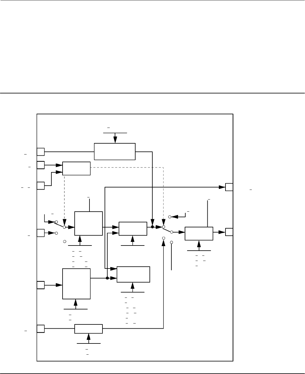
Instruction Manual
D103412X012
Detailed Setup—PID Function Block
January 2015
103
α: fixed smoothing factor of 0.1 applied to RATE
F: feedforward control contribution from the feedforward input (FF_VAL)
E: error between setpoint and process variable
To further customize the block for use in your application, you can configure filtering, feedforward inputs, tracking
inputs, setpoint and output limiting, PID equation structures, and block output action. Table 4‐32 lists the PID block
parameters and their descriptions, units of measure, and index numbers, and figure 4‐10 illustrates the internal
components of the PID function block.
Figure 4‐10. PID Function Block Schematic
B2721
FF VAL
Alarm
Detection Operator
Output
PID
Equation
Setpoint
Limiting
Feedforward
Calculation
BKCAL OUT
OUT
RCAS OUT
FF GAIN
FF SCALE
PV SCALE
PV FILTER
SP HI LIM
SP LO LIM
SP RATE DN
SP RATE UP
Output
Limiting
MODE
BKCAL IN
TRK IN D
CAS IN
IN
TRK VAL
RCAS IN
Scaling
and
Filtering
TRK SCALE
OUT SCALE
Convert
ROUT OUT
ROUT IN
OUT HI LIM
OUT LO LIM
OUT SCALE
HI HI LIM
HI LIM
DV HI LIM
DV LO LIM
LO LIM
LO LO LIM
Operator
Setpoint GAIN
RATE
RESET

Instruction Manual
D103412X012
Detailed Setup—PID Function Block
January 2015
104
Modes
The PID function block supports the following modes:
Manual (Man)—The block output (OUT [9]) may be set manually.
Automatic (Auto)—The SP [8] may be set manually and the block algorithm calculates OUT [9].
Cascade (Cas)—The SP [8] is calculated in another block and is provided to the PID block through the CAS_IN [18]
connection.
RemoteCascade (RCas)—The SP [8] is provided by a host computer that writes to the RCAS_IN [32] parameter.
RemoteOutput (ROut)—The OUT [9] is provided by a host computer that writes to the ROUT_IN [33] parameter.
Local Override (LO)—The track function is active. OUT [9] is set by TRK_VAL [39]. The BLOCK_ERR [6] parameter
shows Local override.
Initialization Manual (IMan)—The output path is not complete (for example, the cascade-to-slave path might not be
open). In IMan mode, OUT [9] tracks BKCAL_IN [27].
Out of Service (OOS)—The block is not processed. The OUT [9] status is set to Bad: Out of Service. The BLOCK_ERR
[6] parameter shows Out of service.
You can configure the Man, Auto, Cas, and OOS modes as permitted modes for operator entry.
Mode Handling
Shed Options—RCAS Mode Only
Shed from or climb to a remote mode is determined by the parameter SHED_OPT [34]. A block climbs and sheds
through the same path. For example, if SHED_OPT [34] specifies that a block should shed to Auto, then, if the block
target mode is set to RCas, the block goes through Auto on the way to RCas. You can configure the shed option as
follows:
Shed With Return Options
Remote cascade or remote output connection failure shifts actual mode but keeps trying to restore remote cascade or
remote output (in other words, the remote cascade or remote output target mode stays in effect).
Normal—On failure of a remote connection, the block attempts to attain the highest permitted non‐remote mode
until the remote connection is restored. Cas is the highest permitted non‐remote mode and Auto is is the next highest
permitted non‐remote mode. If Cas or Auto are not available, the block will shed by default to Man.
Retained Target—The retained target mode is the mode the block was in before changing to one of the remote target
modes. On failure of a remote connection, the block attempts to attain the retained target mode.
Auto—On failure of a remote connection, the block attempts to attain Auto, if permitted, until the remote connection
is restored.
Man—On failure of a remote connection, the block sheds to Man until a remote connection is restored.

Instruction Manual
D103412X012
Detailed Setup—PID Function Block
January 2015
105
Shed With No Return Options
For any shed with no return option, the target mode changes as determined by the option. Therefore, there is no
attempt to restore the connection following failure. The behavior on change to a remote target mode is identical to
that for Shed With Return Options.
Normal—On failure of a remote connection, the block sets the target mode to the highest permitted non‐remote
mode. Cas is the highest permitted non‐remote mode and Auto is is the next permitted non‐remote mode. If Cas or
Auto are not available, the block will shed by default to Man.
Retained Target—The retained target mode is the mode the block was in before changing to one of the remote target
modes. On failure of a remote connection, the block sets the target mode to the retained target mode.
Auto—On failure of a remote connection, the block sets the target mode to Auto, if permitted.
Man—On failure of a remote connection, the block sets the target mode to Man, if permitted.
The user may configure SHED_OPTS [34] so that it calls for a target mode that is not permitted. When doing this, the
mode logic uses the following rules as applied by the remote logic:
Shed logic never results in a non‐permitted target mode.
Shed logic never attempts to attain an actual mode of Auto or Cas if that mode is not permitted.
Status Handling
If the input status on the PID block is Bad, the mode of the block reverts to Manual. In addition, you can select the
Target to Manual if Bad IN status option to direct the target mode to revert to manual. You can set the status option in
Manual or Out of Service mode only.
Set Point Selection and Limiting
The set point of the PID block is only valid when the block is in Auto, Cas, or RCas. Figure 4‐11 illustrates the method
for set point selection. You can configure the SP_HI_LIM [21] and SP_LO_LIM [22] parameters to limit the set point. In
Cascade or Remote Cascade mode, the set point is adjusted by another function block or by a host computer, and the
output is computed based on the set point.
Figure 4‐11. PID Function Block Set Point Selection
B2722
Setpoint
Limiting
SP HI LIM
SP LO LIM
Auto
Man
CAS
SP RATE UP
SP RATE DN
Operator
Set point
Rate
Limiting
Auto
Man
CAS
In Automatic mode, the set point is entered manually by the operator, and the output is computed based on the set
point. In Auto mode, you can also adjust the set point limit and the set point rate of change using the SP_RATE_UP
[20] and SP_RATE_DN [19] parameters.

Instruction Manual
D103412X012
Detailed Setup—PID Function Block
January 2015
106
In Manual mode the output is entered manually by the operator. In Remote Output mode, the output is entered by a
host computer.
Output Selection and Limiting
Output selection is determined by the mode and the set point. In Automatic, Cascade, or Remote Cascade mode, the
output is computed by the PID control equation. In Manual and Remote Output mode, the output may be entered
manually (see also Set Point Selection and Limiting). You can limit the output by configuring the OUT_HI_LIM [28] and
OUT_LO_LIM [29] parameters.
Filtering
The filtering feature changes the response time of the device to smooth variations in output readings caused by rapid
changes in input. You can adjust the filter time constant (in seconds) using the PV_FTIME [16] or SP_FTIME [69]
parameters. Set the filter time constant to zero to disable the filter feature.
Feedforward Calculation
The feedforward value (FF_VAL [40]) is scaled (FF_SCALE [41]) to a common range for compatibility with the output
scale (OUT_SCALE [11]). A gain value (FF_GAIN [42]) is applied to achieve the total feedforward contribution.
Output Tracking
Output tracking is enabled through the control options. You can set control options in Manual or Out of Service mode
only.
The Track Enable control option must be set to True for the track function to operate. When the Track in Manual
control option is set to True, the operator cannot override the tracking function in Manual mode. When Track in
Manual is False, the operator can override the tracking function when the block is in Manual mode. Activating the track
function causes the block's actual mode to revert to Local Override.
The TRK_VAL [38] parameter specifies the value to be converted and tracked into the output when the track function
is operating. The TRK_SCALE [37] parameter specifies the range of TRK_VAL [38].
When the TRK_IN_D [38] parameter is True and the Track Enable control option is True, the TRK_VAL [38] input is
converted to the appropriate value and output in units of OUT_SCALE [11].
Set Point Tracking
You can configure the method for tracking the set point by configuring the following control options (CONTROL_OPTS
[12]):
SP-PV Track in Man—Permits the SP [8] to track the PV [7] when the actual mode of the block is Man.
SP-PV Track in LO or IMan—Permits the SP [8] to track the PV [7] when the actual mode of the block is Local Override
(LO) or Initialization Manual (IMan).
SP-PV Track in ROUT—Permits the SP [8] to track the PV [7] when the actual mode of the block is RemoteOut
(ROUT).
SP Track retained Target—Causes the set point to track the RCAS or CAS parameter based on the retained target
mode when the actual mode is MAN or LO.

Instruction Manual
D103412X012
Detailed Setup—PID Function Block
January 2015
107
Act On IR—If this option is true, then when IR (Initialization Requested) is received on BKCAL_IN [27], the SP [8] will
be adjusted within setpoint limits to provide bumpless transfer when the cascade is closed. If the setpoint required
to provide bumpless transfer is outside the setpoint limits, then any difference added to provide bumpless transfer
will be removed in the BAL_TIME [25].
When one of these options is set, the SP[8] value is set to the PV [7] value while in the specified mode.
You can select the value that a master controller uses for tracking by configuring the Use PV for BKCAL_OUT control
option. The BKCAL_OUT [31] value tracks the PV value. BKCAL_IN [27] on a master controller connected to
BKCAL_OUT [31] on the PID block in an open cascade strategy forces its OUT [9] to match BKCAL_IN [27], thus
tracking the PV from the slave PID block into its cascade input connection (CAS_IN [18]). If the Use PV for BKCAL_OUT
option is not selected, the working set point (SP_WRK [68]) is used for BKCAL_OUT [31].
You can set control options in Manual or Out of Service mode only. When the mode is set to Auto, the SP [8] will
remain at the last value (it will no longer follow the PV [7].
PID Equation Structures for Enhanced PID Block
Note
Extended parameters are not available at this time for all host systems. Refer to your host system documentation, or contact your
Emerson Process Management sales office for additional information.
Configure the STRUCTURECONFIG [71] parameter to select the PID equation structure. You can select one of the
following choices:
Proportional, integral, and derivative on error (PID)
Proportional and integral on error, derivative on PV (PI_D)
Integral on error, proportional and derivative on PV (I_PD)
Proportional on error, derivative on error (PD)
Integral on error, derivative on error (ID)
Integral on error, derivative on PV (I_D)
Two degrees of Freedom (2DOF)
Reverse and Direct Action
To configure the block output action, set the Direct Acting control option. This option defines the relationship
between a change in PV [7] and the corresponding change in output. With Direct Acting enabled (True), an increase in
PV results in an increase in the output.
You can set control options in Manual or Out of Service mode only.
Alarm Detection
A block alarm will be generated whenever the BLOCK_ERR [6] has an error bit set. The types of block error for the PID
block are defined above.

Instruction Manual
D103412X012
Detailed Setup—PID Function Block
January 2015
108
Process alarm detection is based on the PV [7] value. You can configure the alarm limits of the following standard
alarms:
High (HI_LIM [51])
High high (HI_HI_LIM [49])
Low (LO_LIM [53])
Low low (LO_LO_LIM [55])
Additional process alarm detection is based on the difference between SP [8] and PV [7] values and can be configured
via the following parameters:
Deviation high (DV_HI_LIM [57])
Deviation low (DV_LO_LIM [59])
In order to avoid alarm chattering when the variable is oscillating around the alarm limit, an alarm hysteresis in percent
of the PV span can be set using the ALARM_HYS [47] parameter. The priority of each alarm is set in the following
parameters:
HI_PRI [50]
HI_HI_PRI [48]
LO_PRI [52]
LO_LO_PRI [54]
DV_HI_PRI [56]
DV_LO_PRI [58]
Alarms are grouped into five levels of priority, as shown in table 4‐30.
Table 4‐30. PID Function Block Alarm Priorities
Priority Number Priority Description(1)
0The alarm is disabled
1An alarm condition with a priority of 1 can be recognized by the system. The device monitors the alarm but does not report it
until requested by the host system.
2An alarm condition with a priority of 2 is reported to the operator, but generally does not require operator attention (such as
diagnostics and system alerts).
3-7 Alarm conditions of priority 3 to 7 are advisory alarms of increasing priority.
8-15 Alarm conditions of priority 8 to 15 are critical alarms of increasing priority.
1. The priority classes “advise” and critical” have no relationship to Plant Web Alerts.
Application Information
The PID function block is a powerful, flexible control algorithm that is designed to work in a variety of control
strategies. The PID block is configured differently for different applications.
DeltaV Tune
DeltaV Tune quickly and automatically determines optimal tuning parameters for PID control loops. For more
information on DeltaV Tune, refer to DeltaV Books Online or DeltaV documentation.
Block Errors
Table 4‐31 lists conditions reported in the BLOCK_ERR [6] parameter. Conditions in italics are not applicable for the PID
block and are provided only for your reference.

Instruction Manual
D103412X012
Detailed Setup—PID Function Block
January 2015
109
Table 4‐31. BLOCK_ERR Conditions
Condition Number Condition Name and Description
0Other (N/A)
1Block Configuration Error—SHED_OPT or BYPASS set to 0
2Link Configuration Error (N/A)
3Simulate Active (N/A)
4Local Override—The actual mode is LO and Track Enable is set.
5Device Fault State Set (N/A)
6Device Needs Maintenance Soon (N/A)
7Input failure/process variable has Bad status—The parameter linked to IN is indicating a Bad status.
8Output Failure (N/A)
9Memory Failure (N/A)
10 Lost Static Data (N/A)
11 Lost NV Data (N/A)
12 Readback Check Failed (N/A)
13 Device Needs Maintenance Now (N/A)
14 Power Up—Set if devices was powered up with this block in Out of Service (OOS) mode. Cleared on first change of mode to other
than OOS.
15 Out of Service—The actual mode is Out of Service (OOS).
PID Function Block Parameter List (table 4‐32)
Read/Write Capability: RO - Read Only, RW - Read Write
Mode: The block mode(s) required to write to the parameter
Double indentation and shaded Index Number indicates sub‐parameter
Table 4‐32. PID Function Block System Parameters Definitions
Label
PARAMETER_NAME
Index
Number
RO /
RW
Block
Mode Range Initial Value Description
Static Revision
ST_REV 1 RO N/A 0 to 65535 0
Data Type: Unsigned16
The revision level of the static data associated with
the function block. The revision value will be
incremented each time a static pa rameter value in
the block is changed.
Tag Description
TAG_DESC 2 RW ALL 7 bit ASCII Spaces
Data Type: Octet String
The user description of the intended application of
the block.
Strategy
STRATEGY 3 RW ALL 0 to 65535 0
Data Type: Unsigned16
The strategy field can be used to identify grouping
of blocks. This data is not checked or processed by
the block.
Alert Key
ALERT_KEY 4 RW ALL 0 to 255 0
Data Type: Unsigned8
The identification number of the plant unit. This
information may be used in the host for sorting
alarms, etc.
Block Mode
MODE_BLK 5
Data Type: DS‐69
Valid Bits: 7: OOS, 6: IMAN, 5: LO, 4: MAN, 3:
AUTO, 2: CAS, 1: RCAS, 0: ROUT
The actual, target, permitted, and normal modes
of the block.
Target: The requested block mode
Actual: The current mode of the block
Permitted: Allowed modes for Target
Normal: Most common mode for Target
TARGET 5.1 RW ALL OOS, MAN, AUTO
CAS, RCAS, ROUT
OOS until
block is
configured,
then last valid
target
ACTUAL 5.2 RO ALL OOS
PERMITTED 5.3 RW ALL OOS+MAN+AUTO+
CAS+RCAS+ROUT
OOS MAN,
AUTO CAS,
RCAS ROUT
NORMAL 5.4 RW ALL AUTO
-Continued-

Instruction Manual
D103412X012
Detailed Setup—PID Function Block
January 2015
110
Table 4‐32. PID Function Block System Parameters Definitions (Continued)
DescriptionInitial ValueRange
Block
Mode
RO /
RW
Index
Number
Label
PARAMETER_NAME
Block Error
BLOCK_ERR 6 RO N/A
Defined Bits
1: Block Configuration Error
4: Local Override
7: Input Failure/ Bad PV status
14: Power‐up
15: Out‐of‐Service
Dynamic
Data Type: Bit String
0 = inactive
1 = active
This parameter reflects the error status associated
with the hardware or software components
associated with a block. It is a bit string so that
multiple errors may be shown.
Process Value
PV 7 RO N/A Dynamic Data Type: DS‐65
The process variable used in block execution.
Setpoint
SP 8
OOS
MAN
AUTO
PV_SCALE +/- 10% Dynamic
Data Type: DS‐65
The target block setpoint value. It is the result of
setpoint limiting and setpoint rate of change
limiting.
Output
OUT 9MAN
OOS
Status
OUT_SCALE +/- 10% Dynamic DS‐65
The block output value and status.
Value
Process Value Scale
PV_SCALE 10 OOS
EU at 100%
EU at 0%
Units index
Decimal Point
100
0
%
2
Data Type: DS‐68
The high and low scale values, engineering units
code, and number of digits to the right of the
decimal point associated with PV.
Output Scale
OUT_SCALE 11 OOS
EU at 100%
EU at 0%t
Units index
Decimal Point
100
0
%
2
Data Type: DS‐68
The high and low scale values, engineering units
code, and number of digits to the right of the
decimal point associated with OUT.
Grant Deny
GRANT_DENY 12
Data Type: DS‐70
Options for controlling access of host computers
and local control panels to operating, tuning, and
alarm parameters of the block. Not used by the
device.
GRANT: 0=N/A, 1=granted
DENY: 0 = N/A, 1= denied
GRANT 12.1 ALL
0: Program
1: Tune
2: Alarm
3: Local
All bits: 0
DENY 12.2 ALL
0: Program
1: Tune
2: Alarm
3: Local
All bits: 0
Control Options
CONTROL_OPTS 13 OOS
0: Bypass Enable
1: SP tracks PV in MAN
2: SP tracks PV in ROUT
3: SP tracks PV in LO or MAN
4: SP tracks RCAS or CAS in
IMAN, LO, MAN or ROUT
5: Direct Acting
7: Track Enable
8: Track in Manual
9: Use PV for BKCAL_OUT
10: Act on IR
12: Restrict SP to limits in
Cas and RCas
13: No output limits in MAN
All bits: 0
Data Type: Bit String
0=disable
1=enable
Allows you to specify control strategy options.
Status Options
STATUS_OPTS 14 OOS
0: IFS (Initiate Fault State)
if BAD IN
1: IFS if BAD CAS_IN
2: Use Uncertain as Good
5: Target to MAN if BAD IN
All bits: 0
Data Type: Bit String
0=disable
1=enable
Allows you to select options for status handling
and processing.
Input
IN 15 ALL Status
BAD:
NC:
const Data Type: DS‐65
The primary input value of the block.
Value 0
Process Value Filter Time
PV_FTIME 16 ALL Positive 0
Data Type: Float
The time constant of the first-order PV filter. It is
the time, in seconds, required for a 63 percent
change in the IN value.
-Continued-

Instruction Manual
D103412X012
Detailed Setup—PID Function Block
January 2015
111
Table 4‐32. PID Function Block System Parameters Definitions (Continued)
DescriptionInitial ValueRange
Block
Mode
RO /
RW
Index
Number
Label
PARAMETER_NAME
Bypass
BYPASS 17 MAN
OOS
1=Off
2=On 0=undefined
Data Type: Enum
Used to override the calculation of the block.
When enabled, the SP is sent directly to the
output.
Cascade Input
CAS_IN 18 ALL Status
BAD
NC:
const Data Type: DS‐65
The setpoint value from another block.
Value 0
Setpoint Rate Down
SP_RATE_DN 19 ALL Positive + INF
Data Type: Float
Ramp rate for downward SP changes. When the
ramp rate is set to zero, the SP is used
immediately. PV per second
Setpoint Rate UP
SP_RATE_UP 20 ALL Positive + INF
Data Type: Float
Ramp rate for upward SP changes. When the ramp
rate is set to zero, the SP is used immediately. PV
per second
Setpoint High Limit
SP_HI_LIM 21 ALL PV Scale +/- 10%, must be
greater than SP_LO_LIM 100 Data Type: Float
The highest SP value allowed.
Setpoint Low Limit
SP_LO_LIM 22 ALL
PV Scale
+/- 10%, must be less than
SP_HI_LIM
0Data Type: Float
The lowest SP value allowed.
Gain
GAIN 23 ALL greater than 0 1Data Type: Float
The proportional gain value.
Reset
RESET 24 ALL Positive + INF
Data Type: Float
The integral action time constant. Seconds per
repeat
Balance Time
BAL_TIME 25 ALL Positive 0
Data Type: Float
The specified time, in seconds, for the internal
working value of bias to return to the operator set
bias. Also used to specify the time constant at
which the integral term will move to obtain
balance when the output is limited and the mode is
AUTO, CAS, or RCAS.
Rate
RATE 26 ALL Positive 0 Data Type: Float
The derivative action time constant, in seconds.
Back Calculation Input
BKCAL_IN 27 ALL Status
BAD:
NC:
const
Data Type: DS‐65
The analog input value and status from another
block's BKCAL_OUT output that is used for
backward output tracking for bumpless transfer
and to pass limit status.
Value 0
Output High Limit
OUT_HI_LIM 28 ALL OUT_SCALE +/- 10% 100
Data Type: Float
Limits the maximum output value for modes other
than manual.
Output Low Limit
OUT_LO_LIM 29 ALL OUT_SCALE +/- 10% 0
Data Type: Float
Limits the minimum output value for modes other
than manual.
Back Calculation Hysteresis
BKCAL_HYS 30 ALL 0 to 50% 0.50%
Data Type: Float
The amount the output value must change away
from the its output limit before limit status is
turned off.
Back Calculation Output
BKCAL_OUT 31 RO N/A Dynamic
Data Type: DS‐65
The value and status required by the BKCAL_IN
input of another block to prevent reset windup and
to provide bumpless transfer of closed loop
control.
Remote Cascade Input
RCAS_IN 32 ALL Status
BAD:
NoCom:
NoVal:
const
Data Type: DS‐65
Target setpoint and status that is provided by a
supervisory host. Used when mode is RCAS.
Value 0 Trk
-Continued-

Instruction Manual
D103412X012
Detailed Setup—PID Function Block
January 2015
112
Table 4‐32. PID Function Block System Parameters Definitions (Continued)
DescriptionInitial ValueRange
Block
Mode
RO /
RW
Index
Number
Label
PARAMETER_NAME
Remote Out Input
ROUT_IN 33 ALL Status
BAD:
NoCom:
NoVal:
const
Data Type: DS‐65
Target output and status that is provided by a
supervisory host. Used when mode is ROUT.
Value 0 Trk
Shed Options
SHED_OPT 34 ALL
0=Invalid
1=Normal Shed, Normal
Return
2=Normal Shed, No Return
3=Shed to Auto, normal
return
4=Shed to Auto, no return.
Target mode changes to
Auto on detection of a shed
condition
5=Shed to Manual, normal
return
6=Shed to Manual, No
return. Target mode
changes to MAN on
detection of a shed
condition.
7=Shed to retained target,
normal return
8=Shed to retained target,
no return. (Change target to
retained target)
0=Invalid
Data Type: Uint8
Defines action to be taken on remote control
device timeout.
Normal Return - actual mode changes to the next
lowest priority non-remote mode permitted but
returns to the target remote mode when the
remote computer completes the initialization
handshake.
No Return - Target mode changes to the next
lowest priority non-remote mode permitted. The
target remote mode is lost, so no return occurs.
Remote Cascade Output
RCAS_OUT 35 RO N/A Dynamic
Data Type: DS‐65
Block setpoint and status after ramping, filtering,
and limiting that is provided to a supervisory host
for back calculation to allow action to be taken
under limiting conditions or mode change. Used
when mode is RCAS.
Remote Out Output
ROUT_OUT 36 RO N/A Dynamic
Data Type: DS‐65
Block output that is provided to a supervisory host
for a back calculation to allow action to be taken
under limiting conditions or mode change. Used
when mode is RCAS.
Tracking Scale
TRK_SCALE 37 MAN
OOS
100
0
%
2
Data Type: DS‐68
The high and low scale values, engineering units
code, and number of digits to the right of the
decimal point associated with the external tracking
value (TRK_VAL).
Tracking Input Discrete
TRK_IN_D 38 ALL Status
BAD:
NC:
const
Data Type: DS‐66
Discrete input that initiates external tracking of the
block output to the value specified by TRK_VAL.
Value 0
Tracking Value
TRK_VAL 39 ALL Status
BAD:
NC:
const
Data Type: DS‐65
The value (after scaling from TRK_SCALE to
OUT_SCALE) applied to OUT in LO mode when
external tracking is enabled by TRK_IN_D.
Value 0
Feed Forward Value
FF_VAL 40 ALL Status
BAD:
NC:
const Data Type: DS‐65
The feedforward control input value and status.
Value 0
Feed Forward Scale
FF_SCALE 41 MAN
OOS
100
0
%
2
Data Type: DS‐68
The high and low scale values, engineering units
code, and number of digits to the right of the
decimal point associated with the feedforward
value (FF_VAL).
Feed Forward Gain
FF_GAIN 42 MAN
OOS 0
Data Type: Float
The feedforward gain value. FF_VAL is multiplied
by FF_GAIN before it is added to the calculated
control output. A value of 0 disables feedforward.
-Continued-

Instruction Manual
D103412X012
Detailed Setup—PID Function Block
January 2015
113
Table 4‐32. PID Function Block System Parameters Definitions (Continued)
DescriptionInitial ValueRange
Block
Mode
RO /
RW
Index
Number
Label
PARAMETER_NAME
Update Event
UPDATE_EVT 43
Data Type: DS‐73
This alert is generated by any changes to the static
data.
UNACKNOWLEDGED 43.1 RW N/A
0=Undefined
1=Acknowledged
2=Unacknowledged
0
UPDATE_STATE 43.2 RO N/A
0=Undefined
1=Update reported
2=Update not reported
0
TIME_STAMP 43.3 RO N/A 0
STATIC_REVISION 43.4 RO N/A 0
RELATIVE_INDEX 43.5 RO N/A 0
Block Alarm
BLOCK_ALM 44
Data Type: DS‐72
The block alarm is used for all configuration,
hardware, connection failure, or system problems
in the block. The cause of the alarm will be set in
the subcode.
VALUE Data Type: Unsigned8
UNACKNOWLEDGED 44.1 RW N/A
0=Undefined
1=Acknowledged
2=Unacknowledged
0
ALARM_STATE 44.2 RO N/A
0=Undefined
1=Clear‐reported
2=Clear‐not reported
3=Active reported
4=Active not reported
0
TIME_STAMP 44.3 RO N/A 0
SUBCODE 44.4 RO N/A 0
VALUE 44.5 RO N/A 0
Alarm Summary
ALARM_SUM 45
Data Type: DS‐74
Current alert status, unacknowledged states,
unreported states, and disabled states of the
alarms associated with the function block.
CURRENT 45.1 RO ALL 1: High High Alarm
2: High Alarm
3: Low Low Alarm
4: Low Alarm
5: Deviation High Alarm
6: Deviation Low Alarm
7: Block Alarm
Dynamic
UNACKNOWLEDGED 45.2 RO ALL
UNREPORTED 45.3 RO ALL
DISABLED 45.4 RW ALL
Acknowledge Option
ACK_OPTION 46 N/A
1: High High Alarm
2: High Alarm
3: Low Low Alarm
4: Low Alarm
5: Deviation High Alarm
6: Deviation Low Alarm
7: Block Alarm
All bits: 0
Data Type: Bit String
0=Disable
1=Enable
Used to set auto acknowledgment of alarms.
Alarm Hysteresis
ALARM_HYS 47 ALL 0 to 50% 0.50%
Data Type: Float
The amount the alarm value must return to within
the alarm limit before the associated active alarm
condition clears.
High High Priority
HI_HI_PRI 48 ALL 0 to 15 0Data Type: Unsigned8
The priority of the HI HI Alarm.
High High Limit
HI_HI_LIM 49 ALL PV_SCALE, or +INF +INF
Data Type: Float
The setting for the alarm limit used to detect the
HI HI alarm condition.
High Priority
HI_PRI 50 ALL 0 to 15 0Data Type: Unsigned8
The priority of the HI alarm.
High Limit
HI_LIM 51 ALL PV_SCALE, or +INF +INF
Data Type: Float
The setting for the alarm limit used to detect the
HI alarm condition.
Low Priority
LO_PRI 52 ALL 0 to 15 0Data Type: Unsigned8
The priority of the LO alarm.
Low Limit
LO_LIM 53 ALL PV_SCALE, or -INF -INF
Data Type: Float
The setting for the alarm limit used to detect the
LO alarm condition.
Low Low Priority
LO_LO_PRI 54 ALL 0 to 15 0Data Type: Unsigned8
The priority of the LO LO alarm.
-Continued-

Instruction Manual
D103412X012
Detailed Setup—PID Function Block
January 2015
114
Table 4‐32. PID Function Block System Parameters Definitions (Continued)
DescriptionInitial ValueRange
Block
Mode
RO /
RW
Index
Number
Label
PARAMETER_NAME
Low Low Limit
LO_LO_LIM 55 ALL PV_SCALE, or -INF -INF
Data Type: Float
The setting for the alarm limit used to detect the
LO LO alarm condition.
Deviation High Priority
DV_HI_PRI 56 ALL 0 to 15 0Data Type: Unsigned8
The priority of the deviation high alarm.
Deviation High Limit
DV_HI_LIM 57 ALL PV_SCALE, or +INF +INF
Data Type: Float
The setting for the alarm limit used to detect the
deviation high alarm condition.
Deviation Low Priority
DV_LO_PRI 58 ALL 0 to 15 0Data Type: Unsigned8
The priority of the deviation low alarm.
Deviation Low Limit
DV_LO_LIM 59 ALL -INF, or -PV span to 0 -INF
Data Type: Float
The setting for the alarm limit use to detect the
deviation low alarm condition.
High High Alarm
HI_HI_ALM 60
Data Type: DS‐71
The HI HI alarm data, which includes a value of the
alarm, a timestamp of occurrence, and the state of
the alarm.
VALUE Data Type: Float
UNACKNOWLEDGED 60.1 RW N/A
0=Undefined
1=Acknowledged
2=Unacknowledged
0=undefined
ALARM_STATE 60.2 RO N/A
0=Undefined
1=Clear reported
2=Clear not reported
3=Active reported
4=Active not reported
0=undefined
TIME_STAMP 60.3 RO N/A 0
SUBCODE 60.4 RO N/A 0
VALUE 60.5 RO N/A 0
High Alarm
HI_ALM 61
Data Type: DS‐71
The HI alarm data, which includes a value of the
alarm, a timestamp of occurrence, and the state of
the alarm.
VALUE Data Type: Float
UNACKNOWLEDGED 61.1 RW N/A
0=Undefined
1=Acknowledged
2=Unacknowledged
0=undefined
ALARM_STATE 61.2 RO N/A
0=Undefined
1=Clear reported
2=Clear not reported
3=Active reported
4=Active not reported
0=undefined
TIME_STAMP 61.3 RO N/A 0
SUBCODE 61.4 RO N/A 0
VALUE 61.5 RO N/A 0
Low Alarm
LO_ALM 62
Data Type: DS‐71
The LO alarm data, which includes a value of the
alarm, a timestamp of occurrence, and the state of
the alarm.
VALUE Data Type: Float
UNACKNOWLEDGED 62.1 RW N/A
0=Undefined
1=Acknowledged
2=Unacknowledged
0=undefined
ALARM_STATE 62.2 RO N/A
0=Undefined
1=Clear reported
2=Clear not reported
3=Active reported
4=Active not reported
0=undefined
TIME_STAMP 62.3 RO N/A 0
SUBCODE 62.4 RO N/A 0
VALUE 62.5 RO N/A 0
-Continued-

Instruction Manual
D103412X012
Detailed Setup—PID Function Block
January 2015
115
Table 4‐32. PID Function Block System Parameters Definitions (Continued)
DescriptionInitial ValueRange
Block
Mode
RO /
RW
Index
Number
Label
PARAMETER_NAME
Low Low Alarm
LO_LO_ALM 63
Data Type: DS‐71
The LO LO alarm data, which includes a value of the
alarm, a timestamp of occurrence, and the state of
the alarm.
VALUE Data Type: Float
UNACKNOWLEDGED 63.1 RW N/A
0=Undefined
1=Acknowledged
2=Unacknowledged
0=undefined
ALARM_STATE 63.2 RO N/A
0=Undefined
1=Clear reported
2=Clear not reported
3=Active reported
4=Active not reported
0=undefined
TIME_STAMP 63.3 RO N/A 0
SUBCODE 63.4 RO N/A 0
VALUE 63.5 RO N/A 0
Deviation High Alarm
DV_HI_ALM 64
Data Type: DS‐71
The DV HI alarm data, which includes a value of the
alarm, a timestamp of occurrence, and the state of
the alarm.
VALUE Data Type: Float
UNACKNOWLEDGED 64.1 RW N/A
0=Undefined
1=Acknowledged
2=Unacknowledged
0=undefined
ALARM_STATE 64.2 RO N/A
0=Undefined
1=Clear reported
2=Clear not reported
3=Active reported
4=Active not reported
0=undefined
TIME_STAMP 64.3 RO N/A 0
SUBCODE 64.4 RO N/A 0
VALUE 64.5 RO N/A 0
Deviation Low Alarm
DV_LO_ALM 65
Data Type: DS‐71
The DV LO alarm data, which includes a value of
the alarm, a timestamp of occurrence, and the
state of the alarm.
VALUE Data Type: Float
UNACKNOWLEDGED 65.1 RW N/A
0=Undefined
1=Acknowledged
2=Unacknowledged
0=undefined
ALARM_STATE 65.2 RO N/A
0=Undefined
1=Clear reported
2=Clear not reported
3=Active reported
4=Active not reported
0=undefined
TIME_STAMP 65.3 RO N/A 0
SUBCODE 65.4 RO N/A 0
VALUE 65.5 RO N/A 0
Extended Parameters
Bias
BIAS 66 ALL OUT_SCALE +/- 10% 0
Data Type: Float
The bias value used to calculate output for a PD
structure.
Error
ERROR 67 RO N/A Dynamic
Data Type: Float
The error (SP-PV) used to determine the control
action.
SP Work
SP_WRK 68 RO N/A Dynamic
Data Type: Float
The working set point of the block after limiting
and filtering is applied. EU of PV_SCALE
SP FTime
SP_FTIME 69 ALL Positive 0
Data Type: Float
The time constant of the first‐order SP filter. It is
the time, in seconds, required for a 63 percent
change in the IN value. Applied after SP rate
limiting.
Math Form
MATHFORM 70 OOS 0=Standard
1=Series 0=Standard Data Type: Unsigned8
Selects equation form (series or standard)
-Continued-

Instruction Manual
D103412X012
Detailed Setup—PID Function Block
January 2015
116
Table 4‐32. PID Function Block System Parameters Definitions (Continued)
DescriptionInitial ValueRange
Block
Mode
RO /
RW
Index
Number
Label
PARAMETER_NAME
Structureconfig
STRUCTURECONFIG 71 OOS
0=PID terms on error
1=PI terms on error, D term
on PV
2=I terms on error, PD term
on PV
3=PD terms on error
4= P term on error, D term
on PV
5=ID terms on error
6=I term on error, D term on
PV
7=2 Deg. of Freedom PID
0=PID terms
on error
Data Type: Unsigned8
Defines PID equation structure to apply controller
action.
UGamma
GAMMA (ugamma) 72 OOS > = 0, < = 1 1.0
Data Type: Float
Fraction of derivative action taken on error versus
PV. For a value of 0.6, then 60% of the derivative
action will be based on error and 40% on PV. The
value of GAMMA may be changed over a range of
0-1 if STRUCTURE is set to Two Degrees of
Freedom Control. Otherwise, it is automatically set
to a value of 1 or 0 based on the Structure
selection.
UBeta
BETA (ubeta) 73 OOS > = 0, < = 1 1.0
Data Type: Float
Fraction of proportional action taken on error
versus PV. For a value of 0.6, then 60% of the
proportional action will be based on error and 40%
on PV. The value of BETA may be changed over a
range of 0-1 if STRUCTURE is set to Two Degrees of
Freedom Control. Otherwise, it is automatically set
to a value of 1 or 0 based on the Structure
selection.
IDeadBand
IDEADBAND 74 OOS Positive 0
Data Type: Float
Integral action stops when ERROR is within
IDEADBAND, proportional and derivative action
continue. EU of PV_SCALE
StdDev
STDDEV 75 RO N/A Dynamic Data Type: Float
Standard deviation of PV.
Cap StdDev
CAP_STDDEV 76 RO N/A Dynamic Data Type: Float
Standard deviation of PV changes.
T Request
T_REQUEST 77 RO ALL
0=Request Tuning
1=Force Tuning
2=Reset Tuner
0Data Type: Bit String
Operator request to initiate/control autotuning.
T State
T_STATE 78 RO NONE 0 Data Type: Unsigned8
Current autotuner state.
T Status
T_STATUS 79 RO N/A
0=Scan Rate Too Low
Warning
1=Insufficient Process
Response (obsolete)
2=Scan Rate Too High
Warning
3=Inverse Direct Acting
Error
4=PV Deviation Too Large
5=Initial PV Deviation Too
Large
6=PV Limited or Constant
7=PV Bad
8=Invalid Mode for Tuning
9=BKCAL_IN Non Good or
Limited
10=Out Limited
11=Bypass Active
12=Mode Changed
13=Tracking Active
14=Disconnected
15=SP Changed
0Data Type: Bit String
Autotuner status.
-Continued-
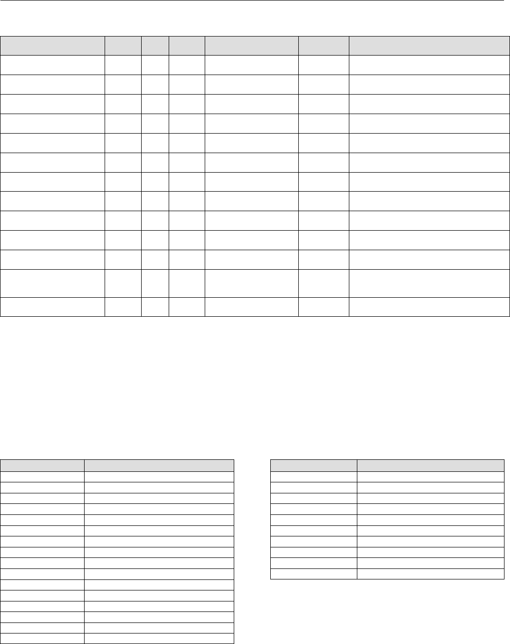
Instruction Manual
D103412X012
Detailed Setup—PID Function Block
January 2015
117
Table 4‐32. PID Function Block System Parameters Definitions (Continued)
DescriptionInitial ValueRange
Block
Mode
RO /
RW
Index
Number
Label
PARAMETER_NAME
T Ipgain
T_IPGAIN 80 RO N/A 0.0 Data Type: Float
Integrated process gain.
T Ugain
T_UGAIN 81 RO N/A 0.0 Data Type: Float
Ultimate gain.
T Uperiod
T_UPERIOD 82 RO N/A 0.0 Data Type: Float
Ultimate period.
T Psgain
T_PSGAIN 83 RO N/A 0.0 Data Type: Float
Process static gain.
T Ptimec
T_PTIMEC 84 RO N/A 0.0 Data Type: Float
Process time constant.
T Pdtime
T_PDTIME 85 RO N/A 0.0 Data Type: Float
Process dead time.
T Targetop
T_TARGETOP 86 ALL 2 Data Type: Unsigned8
Target oscillation periods.
T Hyster
T_HYSTER 87 ALL > = 0.0 0.0 Data Type: Float
Hysteresis
T Relayss
T_RELAYSS 88 ALL > = 0.0 3.0 Data Type: Float
Relay step size.
T Gain Magnifier
T_GAIN_MAGNIFIER 89 ALL > 0.1, < 100 1.0 Data Type: Float
Scales amount of gain.
T Auto Extra DT
T_AUTO_EXTRA_DT 90 ALL 0 Data Type: Unsigned8
Allow additional cycle with extra deadtime.
T Auto Hysteresis
T_AUTO_HYSTERESIS 91 ALL 0
Data Type: Unsigned8
Allows calculation of hysteresis based on
CAP_STDDEV
T Aoperiods
T_AOPERIODS 92 RO N/A 0 Data Type: Unsigned8
Actual oscillation periods.
View Lists
View lists allow the values of a set of parameters to be accessed at the same time. Views 1 and 2 contain operating
parameters and are defined by the Fieldbus Foundation. View 3 contains dynamic parameters and View 4 contains
static parameters with configuration and maintenance information. Views 3 and 4 are defined by the manufacturer.
Table 4‐33. PID Function Block, View 1
Index Number Parameter
1 ST_REV
5.1 MODE_BLK.TARGET_MODE
5.2 MODE_BLK.ACTUAL_MODE
5.3 MODE_BLK.PERMITTED_MODE
5.4 MODE_BLK.NORMAL_MODE
6 BLOCK_ERR
7 PV
8 SP
9 OUT
18 CAS_IN
38 TRK_IN_D
39 TRK_VAL
45.1 ALARM_SUM.CURRENT
45.2 ALARM_SUM.UNACKNOWLEDGED
45.3 ALARM_SUM.UNREPORTED
45.4 ALARM_SUM.DISABLED
Table 4‐34. PID Function Block, View 2
Index Number Parameter
1 ST_REV
10 PV_SCALE
11 OUT_SCALE
12.1 GRANT_DENY.GRANT
12.2 GRANT_DENY.DENY
17 BYPASS
21 SP_HI_LIM
22 SP_LO_LIM
28 OUT_HI_LIM
29 OUT_LO_LIM

Instruction Manual
D103412X012
Detailed Setup—PID Function Block
January 2015
118
Table 4‐35. PID Function Block, View 3
Index Number Parameter
1 ST_REV
5.1 MODE_BLK.TARGET_MODE
5.2 MODE_BLK.ACTUAL_MODE
5.3 MODE_BLK.PERMITTED_MODE
5.4 MODE_BLK.NORMAL_MODE
6 BLOCK_ERR
7 PV
8 SP
9 OUT
15 IN
18 CAS_IN
27 BKCAL_IN
31 BKCAL_OUT
32 RCAS_IN
33 ROUT_IN
35 RCAS_OUT
36 ROUT_OUT
38 TRK_IN_D
39 TRK_VAL
40 FF_VAL
45.1 ALARM_SUM.CURRENT
45.2 ALARM_SUM.UNACKNOWLEDGED
45.3 ALARM_SUM.UNREPORTED
45.4 ALARM_SUM.DISABLED
67 ERROR
68 SP_WORK
71 STRUCTURECONFIG
75 STDDEV
76 CAP_STDDEV
Note
Because individual views are limited in size, View List 4 has
two parts.
Table 4‐36. PID Function Block, View 4.1
Index Number Parameter
1 ST_REV
3 STRATEGY
4 ALERT_KEY
13 CONTROL_OPTS
14 STATUS_OPTS
16 PV_FTIME
19 SP_RATE_DN
20 SP_RATE_UP
23 GAIN
24 RESET
25 BAL_TIME
26 RATE
30 BKCAL_HYS
34 SHED_OPT
37 TRK_SCALE
41 FF_SCALE
42 FF_GAIN
46 ACK_OPTION
47 ALARM_HYS
48 HI_HI_PRI
49 HI_HI_LIM
50 HI_PRI
51 HI_LIM
52 LO_PRI
53 LO_LIM
54 LO_LO_PRI
55 LO_LO_LIM
56 DV_HI_PRI
57 DV_HI_LIM
58 DV_LO_PRI
59 DV_LO_LIM
Table 4‐37. PID Function Block, View 4.2
Index Number Parameter
1 ST_REV
66 BIAS
69 SP_FTIME
70 MATHFORM
71 STRUCTURECONFIG
72 GAMMA (ugamma)
73 BETA
74 IDEADBAND

Instruction Manual
D103412X012
Detailed Setup—PID Function Block
January 2015
119
Field Communicator Menu Structure
Quick Config
Alert Key
Control Options
Deviation High Limit
Deviation Low Limit
Gain
High High Limit
High Limit
Low Limit
Low Low Limit
Output Scale: EU at 100%
Output Scale: EU at 0%
Output Scale: Units Index
Output Scale: Decimal
Process Value Scale: EU at 100%
Process Value Scale: EU at 0%
Process Value Scale: Units Index
Process Value Scale: Decimal
Reset
Setpoint: Status
Setpoint: Value
Setpoint High Limit
Setpoint Low Limit
Common Config
Alarm Hysteresis
Alert Key
Control Options
Deviation High Limit
Deviation Low Limit
Gain
High High Limit
High Limit
Low Limit
Low Low Limit
Block Mode: Target
Block Mode: Actual
Block Mode: Permitted
Block Mode: Normal
Output High Limit
Output Low Limit
Output Scale: EU at 100%
Output Scale: EU at 0%
Output Scale: Units Index
Output Scale: Decimal
Process Value Filter Time
Process Value Scale: EU at 100%
Process Value Scale: EU at 0%
Process Value Scale: Units Index
Process Value Scale: Decimal
Rate
Reset
Setpoint: Status
Setpoint: Value
Setpoint High Limit
Setpoint Low Limit
Advanced Config
Back Calculation Hysteresis
Feed Forward Gain
Feed Forward Scale: EU at 100%
Feed Forward Scale: EU at 0%
Feed Forward Scale: Units Index
Feed Forward Scale: Decimal
Shed Options
Setpoint Rate Down
Setpoint Rate Up
Static Revision
Status Options
Strategy
Tracking Scale: EU at 100%
Tracking Scale: EU at 0%
Tracking Scale: Units Index
Tracking Scale: Decimal
Tracking Value: Status
Tracking Value: Value
Online
Back Calculation Input: Status
Back Calculation Intput: Value
Back Calculation Output: Status
Back Calculation Output: Value
Block Error
Bypass
Cascade Input: Status
Cascade Input: Value
Feed Forward Value: Status
Feed Forward Value: Value
Gain
Input: Status
Input: Value
Block Mode: Target
Block Mode: Actual
Block Mode: Permitted
Block Mode: Normal
Output: Status
Output: Value
Process Value: Status
Process Value: Value
Remote Cascade Input: Status
Remote Cascade Input: Value
Remote Cascade Output: Status
Remote Cascade Output: Value
Remote Out Input: Status
Remote Out Input: Value
Remote Out Output: Status
Remote Out Output: Value
Setpoint: Status
Setpoint: Value
Tracking Input Discrete: Status
Tracking Input Descrete: Value
Tracking Value: Status
Tracking Value: Value
Status
Block Error
Connectors
Back Calculation Input: Status
Back Calculation Intput: Value
Back Calculation Output: Status
Back Calculation Output: Value
Cascade Input: Status
Cascade Input: Value
Feed Forward Value: Status
Feed Forward Value: Value
Input: Status
Input: Value
Output: Status
Ouput: Value
Tracking Input Discrete: Status
Tracking Input Descrete: Value
Tracking Value: Status
Tracking Value: Value
PID FUNCTION BLOCK
(menu continued on next page)

Instruction Manual
D103412X012
Detailed Setup—PID Function Block
January 2015
120
All
Characteristics: Block Tag
Static Revision
Tag Description
Strategy
Alert Key
Block Mode: Target
Block Mode: Actual
Block Mode: Permitted
Block Mode: Normal
Block Error
Process Value: Status
Process Value: Value
Setpoint: Status
Setpoint: Value
Output: Status
Output: Value
Process Value Scale: EU at 100%
Process Value Scale: EU at 0%
Process Value Scale: Units Index
Process Value Scale: Decimal
Output Scale: EU at 100%
Output Scale: EU at 0%
Output Scale: Units Index
Output Scale: Decimal
Grant Deny: Grant
Grant Deny: Deny
Control Options
Status Options
Input: Status
Input: Value
Process Value Filter Time
Bypass
Cascade Input: Status
Cascade Input: Value
Setpoint Rate Down
Setpoint Rate Up
Setpoint High Limit
Setpoint Low Limit
Gain
Reset
Balance Time
Rate
Back Calculation Input: Status
Back Calculation Input: Value
Output High Limit
Output Low Limit
Back Calculation Hysteresis
Back Calculation Output: Status
Back Calculation Output: Value
Remote Cascade Input: Status
Remote Cascade Input: Value
Remote Out Input: Status
Remote Out Input: Value
Shed Options
Remote Cascade Output: Status
Remote Cascade Output: Value
Remote Out Output: Status
Remote Out Output: Value
Tracking Scale: EU at 100%
Tracking Scale EU at 0%
Tracking Scale: Units Index
Tracking Scale: Decimal
Tracking Input Discrete: Status
Tracking Input Descrete: Value
Tracking Value: Status
Tracking Value: Value
Feed Forward Value: Status
Feed Forward Value: Value
Feed Forward Scale: EU at 100%
Feed Forward Scale: EU at 0%
Feed Forward Scale: Units Index
Feed Forward Scale: Decimal
Feed Forward Gain
Other
Tag Description
Grant Deny: Grant
Grant Deny: Deny
Balance Time
Update Event: Unacknowledged
Update Event: Update State
Update Event: Time Stamp
Update Event: Static Rev
Update Event: Relative Index
Block Alarm: Unacknowledged
Block Alarm: Alarm State
Block Alarm: Time Stamp
Block Alarm: Subcode
Block Alarm: Value
Alarm Summary: Current
Alarm Summary: Unacknowledged
Alarm Summary: Unreported
Alarm Summary: Disabled
Acknowledge Option
High High Alarm: Unacknowledged
High High Alarm: Alarm State
High High Alarm: Time Stamp
High High Alarm: Subcode
High High Alarm: Float Value
High Alarm: Unacknowledged
High Alarm: Alarm State
High Alarm: Time Stamp
High Alarm: Subcode
High Alarm: Float Value
Low Alarm: Unacknowledged
Low Alarm: Alarm State
Low Alarm: Time Stamp
Low Alarm: Subcode
Low Alarm: Float Value
Low Low Alarm: Unacknowledged
Low Low Alarm: Alarm State
Low Low Alarm: Time Stamp
Low Low Alarm: Subcode
Low Low Alarm: Float Value
Deviation High Alarm: Unacknowledged
Deviation High Alarm: Alarm State
Deviation High Alarm: Time Stamp
Deviation High Alarm: Subcode
Deviation High Alarm: Float Value
Deviation Low Alarm: Unacknowledged
Deviation Low Alarm: Alarm State
Deviation Low Alarm: Time Stamp
Deviation Low Alarm: Subcode
Deviation Low Alarm: Float Value
Bias
Other
(continued)
Error
SP Work
SP FTime
mathform
structureconfig
Ugamma
UBeta
IDeadBand
StdDv
Cap StdDev
T Request
T State
T Status
T Ipgain
T Ugain
T Uperiod
T Psgain
T Ptimec
T Pdtime
T Targetop
T Hyster
T Relayss
T Gain Magnifier
T Auto Extra DT
T Auto Hysteresis
T Aoperiods
All (continued)
Updated Event: Unacknowledged
Update Event: Update State
Update Event: Time Stamp
Update Event: Static Rev
Update Event: Relative Index
Block Alarm: Unacknowledged
Block Alarm: Alarm State
Block Alarm: Time Stamp
Block Alarm: Subcode
Block Alarm: Value
Alarm Summary: Current
Alarm Summary: Unacknowledged
Alarm Summary: Unreported
Alarm Summary: Disabled
Acknowledge Option
Alarm Hysteresis
High High Priority
High High Limit
High Priority
High Limit
Low Priority
Low Limit
Low Low Priority
Low Low Limit
Deviation High Priority
Deviation High Limit
Deviation Low Priority
Deviation Low Limit
High High Alarm: Unacknowledged
High High Alarm: Alarm State
High High Alarm: Time Stamp
High High Alarm: Subcode
High High Alarm: Float Value
High Alarm: Unacknowledged
High Alarm: Alarm State
High Alarm: Time Stamp
High Alarm: Subcode
High Alarm: Float Value
Low Alarm: Unacknowledged
Low Alarm: Alarm State
Low Alarm: Time Stamp
Low Alarm: Subcode
Low Alarm: Float Value
Low Low Alarm: Unacknowledged
Low Low Alarm: Alarm State
Low Low Alarm: Time Stamp
Low Low Alarm: Subcode
Low Low Alarm: Float Value
Deviation High Alarm: Unacknowledged
Deviation High Alarm: Alarm State
Deviation High Alarm: Time Stamp
Deviation High Alarm: Subcode
Deviation High Alarm: Float Value
Deviation Low Alarm: Unacknowledged
Deviation Low Alarm: Alarm State
Deviation Low Alarm: Time Stamp
Deviation Low Alarm: Subcode
Deviation Low Alarm: Float Value
Bias
Error
SP Work
SP FTime
mathform
structureconfig
UGamma
UBeta
IDeadBand
StdDev
PID FUNCTION BLOCK cont.
All (continued)
Cap StdDev
T Request
T State
T Status
T Ipgain
T Ugain
T Uperiod
T Psgain
T Ptimec
T Pdtime
T Targetop
T Hyster
T Relayss
T Gain Magnifier
T Auto Extra DT
T Auto Hysteresis
T Aoperiods

Instruction Manual
D103412X012
Detailed Setup—ISEL Function Block
January 2015
121
Input Selector Function Block
Overview
The Input Selector (ISEL) function block (figure 4‐12) can be used to select the first good, maximum, minimum,
average, or hot backup from as many as eight input values and place it at the output. The block supports signal status
propagation. There is no process alarm detection in the Input Selector function block. Figure 4‐13 illustrates the
internal components of the ISEL function block. Table 4‐40 lists the ISEL block parameters, their index numbers, and
descriptions.
Figure 4‐12. Input Selector Function Block
FIELDBUS_56A
SELECTED
OUT
IN_1
IN_2
IN_3
IN_4
DISABLE_5
DISABLE_6
DISABLE_7
DISABLE_8
OP_SELECT
IN (1−8) =Input used in the selection algorithm.
DISABLE (1−8) = Discrete input used to enable or disable
the associated input channel.
OP_SELECT =Input used to override algorithm.
.
SELECTED
=
The selected channel number.
OUT
=
The block output and status.
OUT_D =Discrete output that signals
IN_5
IN_6
IN_7
IN_8 ISEL OUT_D
DISABLE_1
DISABLE_2
DISABLE_3
DISABLE_4 a selected alarm condition.
Modes
The ISEL function block supports three modes of operation as defined by the MODE_BLK [5] parameter:
Manual (Man)—The block output (OUT [7]) may be entered manually.
Automatic (Auto)—OUT [7] reflects the selected input value.
Out of Service (OOS)—The block is not processed. The BLOCK_ERR [6] parameter shows Out of Service. In this
mode, you can make changes to all configurable parameters. The target mode of a block may be restricted to one
or more of the supported modes.
The Input Selector block Actual mode will be Out of Service if any of the following are true:
The Actual mode of the resource block is not Auto
The Input Selector block Target mode is Out of Service
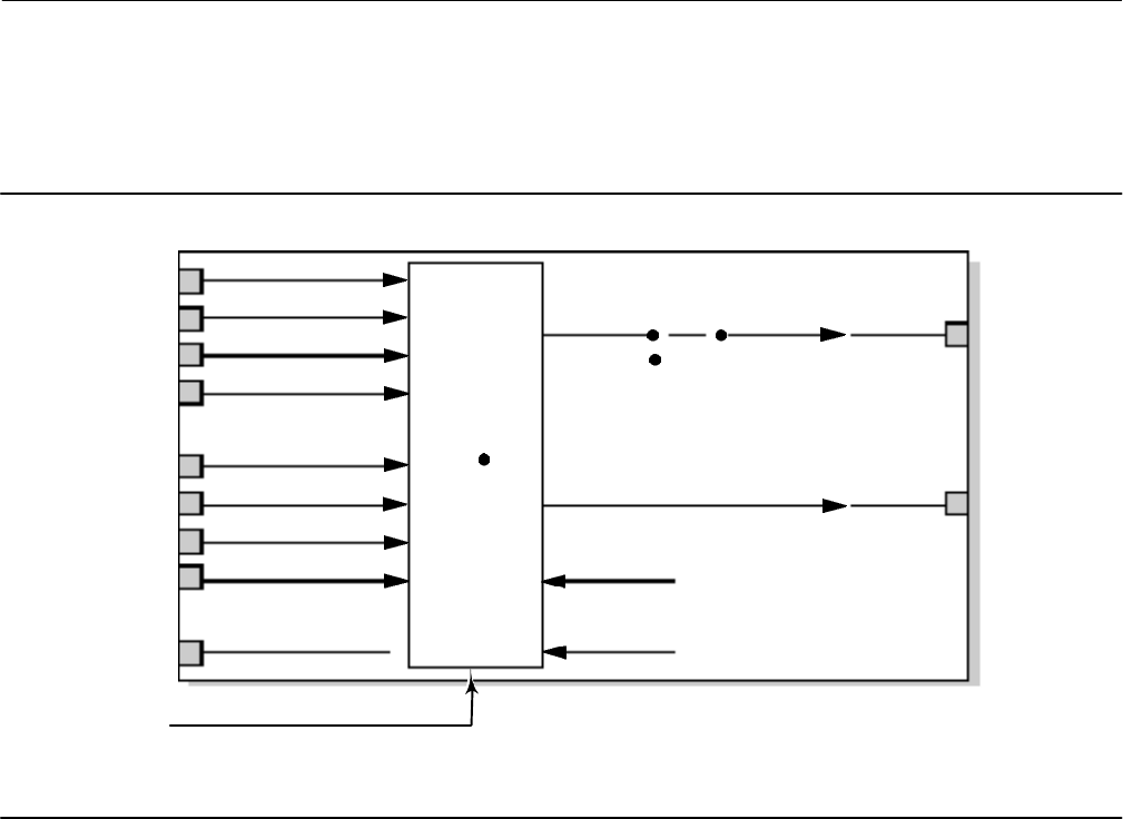
Instruction Manual
D103412X012
Detailed Setup—ISEL Function Block
January 2015
122
The Input Selector block Target mode is Auto, OP_SELECT [22] is not being used, and SELECT_TYPE [19] is 0. In this
case, the BLOCK_ERR [6] parameter shows a Block Configuration Error.
The Input Selector block Actual mode will be Manual if all of the above is not true and the Target mode is Manual.
Figure 4‐13. Input Selector Function Block Schematic
fieldbus−fbus_229a
IN_1
IN_2
IN_3
IN_4
DISABLE_1
DISABLE_2
DISABLE_3
DISABLE_4
OP_SELECT
Selection
Algorithm
AUTO
MAN
OUT
SELECTED
MIN_GOOD
SEL_TYPE
SELECT_TYPE
NOTE: THIS FIGURE DOES NOT INCLUDE THE ADDITIONAL
4 INPUTS IN THE EXTENDED PARAMETERS.
Status Handling
Quality Use and Propagation
In Auto mode, OUT [7] reflects the value and status of the selected input based on the following criteria:
A bad or disabled input is never used by any of the selection algorithms
For a selection algorithm to use an input with status of Uncertain, the STATUS_OPTS [10] parameter must have
“Use Uncertain as Good.”
STATUS_OPTS [10] is applied before selection.
If the number of good inputs is less than MIN_GOOD [20], or if the number of inputs evaluated is 0, the status of
OUT [7] and SELECTED [21] will be Bad.
If an input is disabled or its status is Bad and is selected via OP_SELECT [22], then the status of OUT [7] and
SELECTED [21] will be Bad. If the quality of the input is Uncertain, and the selection for the STATUS_OPTS [10]
parameter is “Use Uncertain as Good,” then the status of OUT [7] and SELECTED [21] will be Uncertain. Otherwise
the status of OUT [7] and SELECTED [21] will be Good Noncascade.

Instruction Manual
D103412X012
Detailed Setup—ISEL Function Block
January 2015
123
When the block is in the Manual mode the status and substatus of OUT [7] and SELECTED [21] will be as follows:
Substatus will be non‐specific and the limit will be constant.
Quality of OUT [7] and SELECTED [21] will be Uncertain if STATUS_OPTS [10] is “Uncertain if in Manual mode.”
Otherwise, the quality of OUT [7] and SELECTED [21] will be Good Noncascade.
Limit Propagation
Refer to figure 4‐14. When SELECT_TYPE [19] is Average, Not Limited is propagated unless all inputs have the same
limit status. If ll inputs have the same limit status, the limit status of the inputs is propagated.
If SELECT_TYPE [19] is Middle and the number of inputs used by the algorithm is greater than one: Not Limited is
propagated unless all selected inputs have the same limit status, in which case the limit status of the inputs is
propagated.
If SELECT_TYPE [19] is Middle and a single input, or if Maximum or Minimum then: If the selected input is a constant
and Middle, Constant is propagated. Otherwise, if the selected input is a constant and Maximum or Minimum,
propagate low if Maximum, propagate high if Minimum. If the selected input is not a constant, propagate selected
input limit as is.
When SELECT_TYPE [19] is First Good or Hot Spare or if OP_SELECT [22] is non‐zero, propagate selected input limit as
is.
Substatus Propagation
Refer to figure 4‐15. For SELECT_TYPE [19] of Maximum, Minimum, First Good, Hot Spare, and Middle with only one
input, simply propagate substatus as is.
For SELECT_TYPE [19] of Maximum and Minimum with more than one input with the same value, propagate substatus
if all inputs are the same.
For SELECT_TYPE [19] of Average or Middle with more than one input, propagate NonSpecific.
If the status of OUT [7] is Bad, then the substatus will be as follows:
Out of Service if the Target mode is Out of Service.
Configuration Error with a BLOCK_ERR [6] of Configuration Error if the Actual mode is Out of Service.
Otherwise a substatus of Non‐Specific.
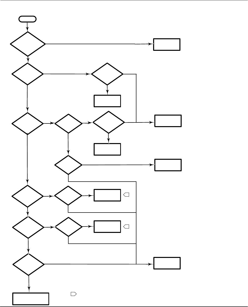
Instruction Manual
D103412X012
Detailed Setup—ISEL Function Block
January 2015
124
Figure 4‐14. Input Selector Block Limit Propagation
START
SELECT_TYPE
Middle?
Yes
No
SELECT_TYPE
Maximum?
SELECT_TYPE
Minimum?
More than 1
input?
Yes All inputs with
same limit
status?
Yes Propagate that
limit status
Input a
constant?
Propagate
Not Limited
No
Propagate
Constant
No
Yes
No
Yes
No
Input a
constant?
Propagate
Low Limit
Propagate
High Limit
Input a
constant?
Yes
SELECT_TYPE
First Good or Hot
Spare?
No
No
No
SELECT_TYPE
Average?
All inputs with
same limit
status?
Propagate
Not Limited
Yes Yes
No
No
1
1
NOTES:
LIMIT MANIPULATION FOR A CONSTANT INPUT FOR MAXIMUM AND MINIMUM IS BASED
UPON THE FOUNDATION FIELDBUS SPECIFICATION. THE REASONING IS BASED ON HIGH SELECT
PROVIDING A LOW LIMIT STATUS AND LOW SELECT PROVIDING A HIGH LIMIT STATUS.
1
Yes
Yes
Propagate
selected input
limit status
OP_SELECT
equal to zero?
Yes
No
Propagate
selected input
limit status
No
Yes
Illegal Select Type
should never be reached
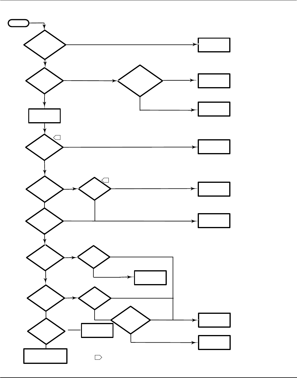
Instruction Manual
D103412X012
Detailed Setup—ISEL Function Block
January 2015
125
Figure 4‐15. Input Selector Block Substatus Propagation
START
Bad
At least 1 good
input?
SELECT_TYPE
Middle or
Average?
Selected in
put status? Propagate Good
Noncascade
Bad
Good
Good
Yes
No
One input?
Yes
No
No
Multiple
Inputs
MODE_BLK
MAN?
STATUS_OPTS Un
certain if Man
Mode?
Propagate Good
Noncascade
Yes Yes
No
No
1
1
NOTES:
1
Yes
Yes
Propagate Bad,
Out of Service
MODE_BLK
OOS?
Yes
No
Propagate
Uncertain
MODE_BLK must
be Auto
OP_SELECT
status?
Propagate Bad,
Nonspecific
OP_SELECT
value >0?
Propagate Bad,
Nonspecific
Yes
No
Propagate
Nonspecific
Propagate input
substatus as is
SELECT_TYPE
Maximum or
Minimum?
One input? Yes
All inputs with
same value?
Propagate input
substatus as is
Yes
No
Propagate
Nonspecific
AN INPUT STATUS MAY BE BAD, GOOD, OR UNCERTAIN. IF BAD, THE INPUT IS NOT USED AND THE STATUS IS PROPAGATED
AS BAD WITH SUBSTATUS NON‐SPECIFIC. IF GOOD IT IS USED AND THE STATUS IS PROPAGATED AS GOOD
(NON‐CASCADE). IF UNCERTAIN, AND STATUS_OPTS IS “USE UNCERTAIN AS GOOD” THEN THE INPUT IS USED AND THE
STATUS IS PROPAGATED AS GOOD (NON‐CASCADE), OTHERWISE IT IS NOT USED AND THE STATUS IS PROPAGATED AS
BAD WITH SUBSTATUS NON‐SPECIFIC.
Multiple
Inputs
Yes
No
SELECT_TYPE Must
be First Good or
Hot Spare?
Illegal Select Type
should never be reached

Instruction Manual
D103412X012
Detailed Setup—ISEL Function Block
January 2015
126
STATUS_OPTS Supported
In the STATUS_OPTS [10] parameter, you can select from the following options to control the status handling:
Use Uncertain as Good—sets the OUT [7] status to Good when the selected input status is Uncertain.
Uncertain if in Manual mode: sets the OUT [7] status to Uncertain when the mode is Manual.
Note
The block mode must be Out of Service to set STATUS_OPTS [10].
Input Selection
The ISEL function block reads the values and statuses of as many as eight inputs (IN_1 [11], IN_2 [12], IN_3 [13], IN_4
[14], IN_5 [25], IN_6 [26], IN_7 [27], IN_8 [28]). To use any of the six selection algorithms to select the output,
OP_SELECT [22] must be 0. To specify which algorithm to use, configure the selector type parameter (SELECT_TYPE
[19]) as follows:
Maximum—selects the input with the highest value from the inputs that are not bad and not disabled.
Minimum—selects the input with the lowest value from the inputs that are not bad and not disabled.
Average—calculates the average value of the inputs that are not bad and not disabled and provides it as the output.
For example, if the number used to average (AVG_USE [33]) is 4 and the number of connected inputs is 6, then the
highest and lowest values would be dropped prior to calculating the average. If AVG_USE [33] is 2 and the number
of connected inputs is 7, then the two highest and lowest values would be dropped prior to calculating the average
and the average would be based on the middle three inputs.
Middle—If the number of good usable inputs is odd, then it selects the middle value. If the number of good usable
inputs is even, then it averages the middle two values and selects status as worst of two. If both inputs' limit status
are not the same then it sets limit status of Not Limited.
First Good—selects the first input that is not bad and not disabled, starting with IN_1 [11].
Hot Spare—initially uses the input selected as first good. If the selected input goes bad, the first good selection is
repeated. If the selected input remains good, it stays selected. If the originally selected input returns to good status
the selection does not change. Selection changes only if the currently selected input goes bad.
Disabling Inputs
Use the parameters DISABLE_1 [15], DISABLE_2 [16], DISABLE_3 [17], DISABLE_4 [18], DISABLE_5 [29], DISABLE_6
[30], DISABLE_7 [31] and DISABLE_8 [32] to disable the corresponding inputs. An input that is disabled will not be used
by any of the selection algorithms.
The status of the disable parameter must be “Good,” “Good_Cascade,” or “Uncertain” with a STATUS_OPTS [10] of
“Use Uncertain as Good” in order to be evaluated. If the status of the disable parameter is Bad, its last usable value is
maintained and acted upon. If the device restarts, losing the last usable value, the last usable value is set to disabled.

Instruction Manual
D103412X012
Detailed Setup—ISEL Function Block
January 2015
127
IN_1 through IN_8 and DISABLE_1 through DISABLE_8 are non‐volatile type parameters so if they are Linked they will
automatically have Bad status until connections are re‐established. If they are not Linked, they will be restored with the
previous value from NVM across device restarts.
Direct Selection of Inputs
The parameter OP_SELECT [22] can be used to select a particular input. If OP_SELECT [22] is non‐zero, the selection
algorithm is bypassed and the value of OP_SELECT [22] is interpreted as the input number to select. If the OP_SELECT
[22] value is greater than the number of inputs, then the highest input is selected. The status of OP_SELECT [22] must
be “Good,” “Good_Cascade,” or “Uncertain” with a STATUS_OPTS [10] of “Use Uncertain as Good” in order to be
evaluated. If the status of OP_SELECT [22] is Bad, then the OUT [7] status is Bad.
Identification of Selected Inputs
For a SELECT_TYPE [19] of Maximum, Minimum, Middle, First Good, and Hot Spare, SELECTED [21] indicates the
number of the selected input. When Middle is computed from more than one input, SELECTED [21] is set to 0.
For a SELECT_TYPE [19] of Average, SELECTED [21] indicates the number of inputs used in the average calculation.
When the block mode is Manual, SELECTED [21] is set to 0.
Alarm Detection
A block alarm will be generated whenever the BLOCK_ERR [6] has an error bit set. The types of block error for the PID
block are defined above.
Process alarm detection is based on OUT [7] value. You can configure the alarm limits of the following standard
alarms:
High (HI_LIM [40])
High high (HI_HI_LIM [38])
Low (LO_LIM [42])
Low low (LO_LO_LIM [44])
In order to avoid alarm chattering when the variable is oscillating around the alarm limit, an alarm hysteresis in percent
of the PV span can be set using the ALARM_HYS [36] parameter. The priority of each alarm is set in the following
parameters:
HI_PRI [39]
HI_HI_PRI [37]
LO_PRI [41]
LO_LO_PRI [43]
ACK_OPTION [35] is used to set automatic acknowledgement of alarms.
ALARM_SUM [34] indicates the current alert status, unacknowledged states, and disabled states of the alarms
associated with the function block.

Instruction Manual
D103412X012
Detailed Setup—ISEL Function Block
January 2015
128
Alarms are grouped into five levels of priority, as shown in table 4‐38.
Table 4‐38. ISEL Function Block Alarm Priorities
Priority Number Priority Description(1)
0The priority of an alarm condition changes to 0 after the condition that caused the alarm is corrected.
1An alarm condition with a priority of 1 can be recognized by the system. The device monitors the alarm but does not report it
until requested by the host system.
2An alarm condition with a priority of 2 is reported to the operator, but generally does not require operator attention (such as
diagnostics and system alerts).
3-7 Alarm conditions of priority 3 to 7 are advisory alarms of increasing priority.
8-15 Alarm conditions of priority 8 to 15 are critical alarms of increasing priority.
1. The priority classes “advise” and “critical” have no relationship to Plant Web Alerts.
Block Errors
Table 4‐39 lists conditions reported in the BLOCK_ERR [6] parameter. Conditions in italics are not applicable for the
ISEL block and are provided only for your reference.
Table 4‐39. BLOCK_ERR Conditions
Condition Number Condition Name and Description
0Other (N/A)
1Block Configuration Error ‐ If OP_SELECT is not being used, and SELECT_TYPE = 0. This implies OP_SELECT status is good and actual
mode is AUTO.
2Link Configuration Error (N/A)
3Simulate Active (N/A)
4Local Override (N/A)
5Device Fault State Set (N/A)
6Device Needs Maintenance Soon (N/A)
7Input failure/process variable has Bad status ‐ Set if any IN or any DISABLE or OP_SELECT is bad and connected. This means that a
status of BAD NC would not cause an input failure but a status of BAD LUV or BAD no LUV would cause and input failure.
8Output failure ‐ Set if OUT quality is bad and the Actual mode is not Out of Service.
9Memory Failure (N/A)
10 Lost Static Data (N/A)
11 Lost NV Data (N/A)
12 Readback Check Failed (N/A)
13 Device Needs Maintenance Now (N/A)
14 Power Up ‐ Set if the Target mode is Out of Service when powered up until the mode is changed.
15 Out of Service ‐ The block is in Out of Service (OOS) mode
ISEL Function Block Parameter List (table 4‐40)
Read/Write Capability: RO - Read Only, RW - Read Write
Mode: The block mode(s) required to write to the parameter
Double indentations and shaded Index Numbers indicate sub‐parameters

Instruction Manual
D103412X012
Detailed Setup—ISEL Function Block
January 2015
129
Table 4‐40. Input Selector Function Block Parameter Definitions
Label
PARAMETER_NAME
Index
Number RO / RW Block
Mode Range Initial
Value Description
Static Revision
ST_REV 1 RO N/A 0 to 65535 0
Data Type: Unsigned16
The revision level of the static data associated with the
function block. The revision value will be incremented
each time a static parameter value in the block is
changed.
Tag Description
TAG_DESC 2 RW ALL 7 bit ASCII spaces
Data Type: Octet String
The user description of the intended application of the
block.
Strategy
STRATEGY 3 RW ALL 0 to 65535 0
Data Type: Unsigned16
The strategy field can be used to identify grouping of
blocks. This data is not checked or processed by the
block.
Alert Key
ALERT_KEY 4 RW ALL 1 to 255 0
Data Type: Unsigned8
The identification number of the plant unit. This
information may be used in the host for sorting alarms,
etc.
Block Mode
MODE_BLK 5
Data Type: DS‐69
Valid Bits: 7: OOS, 4: MAN,
3: AUTO
The actual, target, permitted, and normal modes of the
block.
Target: The requested block mode
Actual: The current mode of the block
Permitted: Allowed modes for Target
Normal: Most common mode for Target
TARGET 5.1 RW ALL OOS, MAN, AUTO
OOS until
block is
configured,
then last
valid target
ACTUAL 5.2 RO ALL
PERMITTED 5.3 RW ALL OOS+MAN+AUTO OOS+MAN
+AUTO
NORMAL 5.4 RW ALL AUTO
Block Error
BLOCK_ERR 6 RO N/A
1: Block
Configuration Error
7: Input Failure / Bad
PV status
8: Output Failure
14: Power Up
15: Out‐of‐Service
Dynamic
Data Type: Bit String
0=Inactive
1=Active
This parameter reflects the error status associated with
the hardware or software components associated with
a block. It is a bit string, so that multiple errors may be
shown.
Output
OUT 7MAN
OOS
Status
OUT_RANGE Dynamic Data Type: DS‐65
The block output value and status.
Value
Output Range
OUT_RANGE 8 ALL
EU at 100%
EU at 0%
Units Index
Decimal Point
100
0
%
2
Data Type: DS‐67
High and low scale values, engineering units code, and
number of digits to the right of the decimal point
associated with OUT.
Grant Deny
GRANT_DENY 9Data Type: DS‐70
Options for controlling access of host computers and
local control panels to operating, tuning, and alarm
parameters of the block. Not used by device.
GRANT: 0=N/A, 1=granted
DENY: 0=N/A, 1=denied
GRANT 9.1 ALL 0: Program
1: Tune
2: Alarm
3: Local
All bits: 0
DENY 9.2 ALL All bits:0
Status Options
STATUS_OPTS 10 OOS
2: Use Uncertain as
GOOD
8: Uncertain if MAN
All bits: 0
Data Type: Bit String
Allows you to select options for status handling and
processing. The supported status option for the input
selector block is: “Use Uncertain as Good”, “Uncertain
if Man mode.”
Input 1
IN_1 11 ALL Status
BAD
NC
constant Data Type: DS‐65
The block input value and status.
Value 0
Input 2
IN_2 12 ALL Status
BAD
NC
constant Data Type: DS‐65
The block input value and status.
Value 0
-Continued-

Instruction Manual
D103412X012
Detailed Setup—ISEL Function Block
January 2015
130
Table 4‐40. Input Selector Function Block Parameter Definitions (Continued)
Description
Initial
Value
Range
Block
Mode
RO / RW
Index
Number
Label
PARAMETER_NAME
Input 3
IN_3 13 ALL Status
BAD
NC
constant Data Type: DS‐65
The block input value and status.
Value 0
Input 4
IN_4 14 ALL Status
BAD
NC
constant Data Type: DS‐65
The block input value and status.
Value 0
Disable Analog Input 1
DISABLE_1 15 ALL
Status
BAD
NC
constant Data Type: DS‐66
Enable/Disable for Input_1, If parameter is TRUE then
input is disabled. If parameter status is BAD it is not
evaluated.
Value
0=Use
1=Disable
0
Disable Analog Input 2
DISABLE_2 16 ALL
Status
BAD
NC
constant Data Type: DS‐66
Enable/Disable for Input_2, If parameter is TRUE then
input is disabled. If parameter status is BAD it is not
evaluated.
Value
0=Use
1=Disable
0
Disable Analog Input 3
DISABLE_3 17 ALL
Status
BAD
NC
constant Data Type: DS‐66
Enable/Disable for Input_3, If parameter is TRUE then
input is disabled. If parameter status is BAD it is not
evaluated.
Value
0=Use
1=Disable
0
Disable Analog Input 4
DISABLE_4 18 ALL
Status
BAD
NC
constant Data Type: DS‐66
Enable/Disable for Input_4, If parameter is TRUE then
input is disabled. If parameter status is BAD it is not
evaluated.
Value
0=Use
1=Disable
0
Select Type
SELECT_TYPE 19 ALL
1=First Good
2=Minimum
3=Maximum
4=Middle
5=Average
6=Hot Spare
0Data Type: Unsigned8
Determines the selector action
Min Good
MIN_GOOD 20 ALL 1 - 4
0 initial value only 0
Data Type: Unsigned8
The minimum number of inputs which are “good” is
less than the value of MIN_GOOD then set the OUT
status to “bad”.
Selected
SELECTED 21 RO N/A
Status Data Type: DS‐66
The integer indicating the selected input number.
Value
0 - 8 Dynamic
Operator Select
OP_SELECT 22 ALL
Status
BAD
NC
constant
Data Type: DS‐66
An operator settable parameter to force a given input
to be used.
Value
0 - 8 0
-Continued-

Instruction Manual
D103412X012
Detailed Setup—ISEL Function Block
January 2015
131
Table 4‐40. Input Selector Function Block Parameter Definitions (Continued)
Description
Initial
Value
Range
Block
Mode
RO / RW
Index
Number
Label
PARAMETER_NAME
Update Event
UPDATE_EVT 23
Data Type: DS‐73
This alert is generated by any change to the static data.
UNACKNOWLEDGED 23.1 RW N/A
0=Undefined
1=Acknowledged
2=Unacknowledged
0
UPDATE_STATE 23.2 RO N/A
0=Undefined
1=Update Reported
2=Updated not
reported
0
TIME_STAMP 23.3 RO N/A 0
STATIC_REVISION 23.4 RO N/A 0
RELATIVE_INDEX 23.5 RO N/A 0
Block Alarm
BLOCK_ALM 24
Data Type: DS‐72
The block alarm is used for all configuration, hardware,
connection failure, or system problems in the block.
The cause of the alert is entered in the subcode field.
The first alert to become active will set the active
status in BLOCK_ERR. As soon as the Unreported status
is cleared by the alert reporting task, another block
alert may be reported without clearing the Active
status, if the subcode has changed.
UNACKNOWLEDGED 24.1 RW N/A
0=Undefined
1=Acknowledged
2=Unacknowledged
0
ALARM_STATE 24.2 RO N/A
0=Undefined
1=Clear reported
2=Clear not reported
3=Active reported
4=Active not
reported
0
TIME_STAMP 24.3 RO N/A 0
SUBCODE 24.4 RO N/A 0
VALUE 24.5 RO N/A 0
Extended Parameters
In 5
IN_5 25 ALL Status
BAD
NC
constant Data Type: DS‐65
Input value and status.
Value 0
In 6
IN_6 26 ALL Status
BAD
NC
constant Data Type: DS‐65
Input value and status.
Value 0
In 7
IN_7 27 ALL Status
BAD
NC
constant Data Type: DS‐65
Input value and status.
Value
In 8
IN_8 28 ALL Status
BAD
NC
constant Data Type: DS‐65
Input value and status.
Value 0
Disable Analog Input 5
DISABLE_5 29 ALL
Status
BAD
NC
constant Data Type: DS‐66
Enable/Disable for Input_5, If parameter is TRUE then
input is disabled. If parameter status is BAD it is not
evaluated.
Value
0=Use
1=Disable
0
Disable Analog Input 6
DISABLE_6 30 ALL
Status
BAD
NC
constant
0
Data Type: DS‐66
Enable/Disable for Input_6, If parameter is TRUE then
input is disabled. If parameter status is BAD it is not
evaluated.
Value
0=Use
1=Disable
0
-Continued-

Instruction Manual
D103412X012
Detailed Setup—ISEL Function Block
January 2015
132
Table 4‐40. Input Selector Function Block Parameter Definitions (Continued)
Description
Initial
Value
Range
Block
Mode
RO / RW
Index
Number
Label
PARAMETER_NAME
Disable Analog Input 7
DISABLE_7 31 ALL
Value
BAD
NC
constant Data Type: DS‐66
Enable/Disable for Input_7, If parameter is TRUE then
input is disabled. If parameter status is BAD it is not
evaluated.
Status
0=Use
1=Disable
0
Disable Analog Input 8
DISABLE_8 32 ALL
Value
BAD
NC
constant Data Type: DS‐66
Enable/Disable for Input_8, If parameter is TRUE then
input is disabled. If parameter status is BAD it is not
evaluated.
Status
0=Use
1=Disable
0
Number used to average
AVG_USE 33 1 to 8 0
Data Type: Unsigned8
Number used to average the output. The number of
min and max dropped is the number of inputs minus
AVG_USE.
Alarm Summary
ALARM_SUM 34
Data Type: DS‐74
Current alert status, unacknowledged states,
unreported states, and disabled states of the alarms
associated with the function block.
CURRENT 34.1 RO NA 1: Hi Hi
2: Hi
3: Lo Lo
4: Lo
UNACKNOWLEDGED 34.2 RO NA
UNREPORTED 34.3 RO NA
DISABLED 34.4 RW ALL
Acknowledge Option
ACK_OPTION 35 ALL
1: Hi Hi
2: Hi
3: Lo Lo
4: Lo
0
Data Type: Bit String
Selection of whether alarms associated with the block
will be automatically acknowledged.
0=Disable
1=Enable
Alarm Hysteresis
ALARM_HYS 36 ALL 0 to 50% 0.50% Data Type: Float
Hysteresis on alarms
High High Priority
HI_HI_PRI 37 ALL 0 TO 15 0Data Type: Unsigned8
Priority of the alarm
High High Limit
HI_HI_LIM 38 ALL 0 Data Type: Float
Value of analog input which will generate an alarm
High Priority
HI_PRI 39 ALL 0 TO 15 0Data Type: Unsigned8
Priority of the alarm
High Limit
HI_LIM 40 ALL 0 Data Type: Float
Value of analog input which will generate an alarm
Low Priority
LO_PRI 41 ALL 0 TO 15 0Data Type: Unsigned8
Priority of the alarm
Low Limit
LO_LIM 42 ALL 0 Data Type: Float
Value of analog input which will generate an alarm
Low Low Priority
LO_LO_PRI 43 ALL 0 TO 15 0Data Type: Unsigned8
Priority of the alarm
Low Low Limit
LO_LO_LIM 44 ALL 0 Data Type: Float
Value of analog input which will generate an alarm
High High Alarm
HI_HI_ALM 45
Data Type: DS‐71
The high high alarm data, which includes a value of the
alarm, a timestamp of occurrence, and the state of the
alarm.
UNACKNOWLEDGED 45.1 RW N/A
0=Undefined
1=Acknowledged
2=Unacknowledged
0
ALARM_STATE 45.2 RO N/A
0=Undefined
1=Clear reported
2=Clear not reported
3=Active reported
4=Active not
reported
0
TIME_STAMP 45.3 RO N/A 0
SUBCODE 45.4 RO N/A 0
VALUE 45.5 RO N/A 0
-Continued-

Instruction Manual
D103412X012
Detailed Setup—ISEL Function Block
January 2015
133
Table 4‐40. Input Selector Function Block Parameter Definitions (Continued)
Description
Initial
Value
Range
Block
Mode
RO / RW
Index
Number
Label
PARAMETER_NAME
High Alarm
HI_ALM 46
Data Type: DS‐71
The high alarm data, which includes a value of the
alarm, a timestamp of occurrence, and the state of the
alarm.
UNACKNOWLEDGED 46.1 RW N/A
0=Undefined
1=Acknowledged
2=Unacknowledged
0
ALARM_STATE 46.2 RO N/A
0=Undefined
1=Clear reported
2=Clear not reported
3=Active reported
4=Active not
reported
0
TIME_STAMP 46.3 RO N/A 0
SUBCODE 46.4 RO N/A 0
VALUE 46.5 RO N/A 0
Low Alarm
LO_ALM 47
Data Type: DS‐71
The low alarm data, which includes a value of the
alarm, a timestamp of occurrence, and the state of the
alarm.
UNACKNOWLEDGED 47.1 RW N/A
0=Undefined
1=Acknowledged
2=Unacknowledged
0
ALARM_STATE 47.2 RO N/A
0=Undefined
1=Clear reported
2=Clear not reported
3=Active reported
4=Active not
reported
0
TIME_STAMP 47.3 RO N/A 0
SUBCODE 47.4 RO N/A 0
VALUE 47.5 RO N/A 0
Low Low Alarm
LO_LO_ALM 48
Data Type: DS‐71
The low low alarm data, which includes a value of the
alarm, a timestamp of occurrence, and the state of the
alarm.
UNACKNOWLEDGED 48.1 RW N/A
0=Undefined
1=Acknowledged
2=Unacknowledged
0
ALARM_STATE 48.2 RO N/A
0=Undefined
1=Clear reported
2=Clear not reported
3=Active reported
4=Active not
reported
0
TIME_STAMP 48.3 RO N/A 0
SUBCODE 48.4 RO N/A 0
VALUE 48.5 RO N/A 0
Output Discrete
OUT_D 49 MAN
OOS
Status Data Type: DS‐66
Discrete output to indicate a selected alarm value
Value
0, 1
Alarm Select
ALM_SEL 50 ALL
Status
Data Type: Bit String
Used to select the process alarm conditions that will
cause the OUT_D parameter to be set.
1: Hi Hi
2: Hi
3: Lo Lo
4: Lo
All bits:0
View Lists
View lists allow the values of a set of parameters to be accessed at the same time. Views 1 and 2 contain operating
parameters and are defined by the Fieldbus Foundation. View 3 contains dynamic parameters and View 4 contains
static parameters with configuration and maintenance information. Views 3 and 4 are defined by the manufacturer.

Instruction Manual
D103412X012
Detailed Setup—ISEL Function Block
January 2015
134
Table 4‐41. ISEL Function Block, View 1
Index Number Parameter
1 ST_REV
5.1 MODE_BLK.TARGET_MODE
5.2 MODE_BLK.ACTUAL_MODE
5.3 MODE_BLK.PERMITTED_MODE
5.4 MODE_BLK.NORMAL_MODE
6 BLOCK_ERR
7 OUT
11 IN_1
12 IN_2
13 IN_3
14 IN_4
15 DISABLE_1
16 DISABLE_2
17 DISABLE_3
18 DISABLE_4
21 SELECTED
22 OP_SELECT
25 IN_5
26 IN_6
27 IN_7
28 IN_8
29 DISABLE_5
30 DISABLE_6
31 DISABLE_7
32 DISABLE_8
34.1 ALARM_SUM.CURRENT
34.2 ALARM_SUM.UNACKNOWLEDGED
34.3 ALARM_SUM.UNREPORTED
34.4 ALARM_SUM.DISABLED
Table 4‐42. ISEL Function Block, View 2
Index Number Parameter
1 ST_REV
8 OUT_RANGE
9.1 GRANT_DENY.GRANT
9.2 GRANT_DENY.DENY
Table 4‐43. ISEL Function Block, View 3
Index Number Parameter
1 ST_REV
5.1 MODE_BLK.TARGET_MODE
5.2 MODE_BLK.ACTUAL_MODE
5.3 MODE_BLK.PERMITTED_MODE
5.4 MODE_BLK.NORMAL_MODE
6 BLOCK_ERR
7 OUT
11 IN_1
12 IN_2
13 IN_3
14 IN_4
15 DISABLE_1
16 DISABLE_2
17 DISABLE_3
18 DISABLE_4
21 SELECTED
22 OP_SELECT
25 IN_5
26 IN_6
27 IN_7
28 IN_8
29 DISABLE_5
30 DISABLE_6
31 DISABLE_7
32 DISABLE_8
34.1 ALARM_SUM.CURRENT
34.2 ALARM_SUM.UNACKNOWLEDGED
34.3 ALARM_SUM.UNREPORTED
34.4 ALARM_SUM.DISABLED
49 OUT_D
Table 4‐44. ISEL Function Block, View 4
Index Number Parameter
1 ST_REV
3 STRATEGY
4 ALERT_KEY
10 STATUS_OPTS
19 SELECT_TYPE
20 MIN_GOOD
33 AVG_USE
35 ACK_OPTION
36 ALARM_HYS
37 HI_HI_PRI
38 HI_HI_LIM
39 HI_PRI
40 HI_LIM
41 LO_PRI
42 LO_LIM
43 LO_LO_PRI
44 LO_LO_LIM
50 ALM_SEL

Instruction Manual
D103412X012
Detailed Setup—ISEL Function Block
January 2015
135
INPUT SELECTOR FUNCTION BLOCK
Quick Config
Alert Key
Min Good
Output Range: EU at 100%
Output Range: EU at 0%
Output Range: Units Index
Output Range: Decimal
Select Type
Common Config
Min Good
Block Mode: Target
Block Mode: Actual
Block Mode: Permitted
Block Mode: Normal
Output Range: EU at 100%
Output Range: EU at 0%
Output Range: Units Index
Output Range: Decimal
Select Type
Advanced Config
Alert Key
Static Revision
Status Options
Strategy
Online
Block Error
Disable Analog Input 1: Status
Disable Analog Input 1: Value
Disable Analog Input 2: Status
Disable Analog Input 2: Value
Disable Analog Input 3: Status
Disable Analog Input 3: Value
Disable Analog Input 4: Status
Disable Analog Input 4: Value
Input 1: Status
Input 1: Value
Input 2: Status
Input 2: Value
Input 3: Status
Input 3: Value
Input 4: Status
Input 4: Value
Block Mode: Target
Block Mode: Actual
Block Mode: Permitted
Block Mode: Normal
Operator Selected: Status
Operator Selected: Value
Output: Status
Output: Value
Selected: Status
Selected: Value
Status
Block Error
All
Characteristics
Static Revision
Tag Description
Strategy
Alert Key
Block Mode: Target
Block Mode: Actual
Block Mode: Permitted
Block Mode: Normal
Block Error
Output: Status
Output: Value
Output Range: EU at 100%
Output Range: EU at 0%
Output Range: Units Index
Output Range: Decimal
Grant Deny: Grant
Grant Deny: Deny
Status Options
Input 1: Status
Input 1: Value
Input 2: Status
Input 2: Value
Input 3: Status
Input 3: Value
Input 4: Status
Input 4: Value
Disable Analog Input 1: Status
Disable Analog Input 1: Value
Disable Analog Input 2: Status
Disable Analog Input 2: Value
Disable Analog Input 3: Status
Disable Analog Input 3: Value
Disable Analog Input 4: Status
Disable Analog Input 4: Value
Select Type
Min Good
Selected: Status
Selected: Value
Operator Select: Status
Operator Select: Value
Update Event: Unacknowledged
Update Event: Update State
Update Event: Time Stamp
Update Event: Static Rev
Update Event: Relative Index
Block Alarm: Unacknowledged
Block Alarm: Alarm State
Block Alarm: Time Stamp
Block Alarm: Subcode
Block Alarm: Value
Analog Input 5: Status
Analog Input 5: Value
Analog Input 6: Status
Analog Input 6: Value
Analog Input 7: Status
Analog Input 7: Value
Analog Input 8: Status
Analog Input 8: Value
Disable Analog Input 5: Status
Disable Analog Input 5: Value
Disable Analog Input 6: Status
Disable Analog Input 6: Value
Disable Analog Input 7: Status
Disable Analog Input 7: Value
Disable Analog Input 8: Status
Disable Analog Input 8: Value
Number Used to average
Connectors
Disable Analog Input 1: Status
Disable Analog Input 1: Value
Disable Analog Input 2: Status
Disable Analog Input 2: Value
Disable Analog Input 3: Status
Disable Analog Input 3: Value
Disable Analog Input 4: Status
Disable Analog Input 4 : Value
Input 1: Status
Input 1: Value
Input 2: Status
Input 2: Value
Input 3: Status
Input 3: Value
Input 4: Status
Input 4: Value
Operator Select: Status
Operator Select: Value
Output: Status
Output: Value
Selected: Status
Selected: Value
Field Communicator Menu Structure
All continued
Alarm Summary: Current
Alarm Summary: Unacknowledged
Alarm Summary: Unreported
Alarm Summary: Disabled
Acknowledge Option
Alarm Hysteresis
High High Priority
High High Limit
High Priority
High Limit
Low Priority
Low Limit
Low Low Priority
Low Low Limit
High High Alarm: Unacknowledged
High High Alarm: Alarm State
High High Alarm: Time Stamp
High High Alarm: Subcode
High High Alarm: Float Value
High Alarm: Unacknowledged
High Alarm: Alarm State
High High Alarm: Time Stamp
High Alarm: Subcode
High Alarm: Float Value
Low Alarm: Unacknowledged
Low Alarm: Alarm State
Low Alarm: Time Stamp
Low Alarm: Subcode
Low Alarm: Float Value
Low Low Alarm: Unacknowledged
Low Low Alarm: Alarm State
Low Low Alarm: Time Stamp
Low Low Alarm: Subcode
Low Low Alarm: Float Value
Alarm Output: Status
Alarm Output: Value
Alarm Select
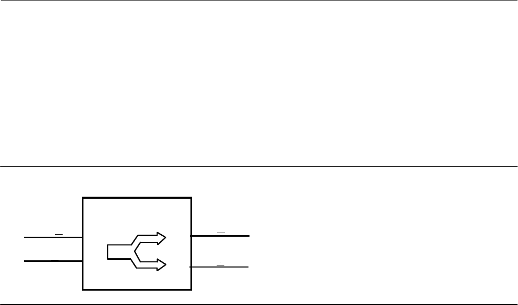
Instruction Manual
D103412X012
Detailed Setup—OS Function Block
January 2015
136
Output Splitter Function Block
Overview
The Output Splitter (OS) block (figure 4‐16) provides the capability to drive two control outputs from a single input.
Each output is a linear function of some portion of the input. Back calculation support is provided using the same linear
function in reverse. Cascade initialization is supported by a decision table for combinations of input and output
conditions.
Figure 4‐16. Output Splitter (OS) Function Block
RCAS IN
CAS IN
OS
OUT 1
OUT 2
This block is normally used in split ranging or sequencing of multiple valve applications. A typical split range
application has both valves closed when the splitter input is 50%. One valve opens fully as the input drops to 0%. The
other valve opens as the input rises above 50%.
A typical sequencing application has both valves closed at 0% input. One valve fully opens as the input rises to 50% and
the other stays shut. The second valve opens as the input rises above 50%, and the first valve may remain open or shut
off quickly.
Because this block is in the control path, it is able to pass limit and cascade initialization information back to the
upstream block. Table 4‐48 lists the OS block parameters and their descriptions, units of measure, and index numbers.
Figures 4‐17 and 4‐18 illustrate the internal components of the OS function block.
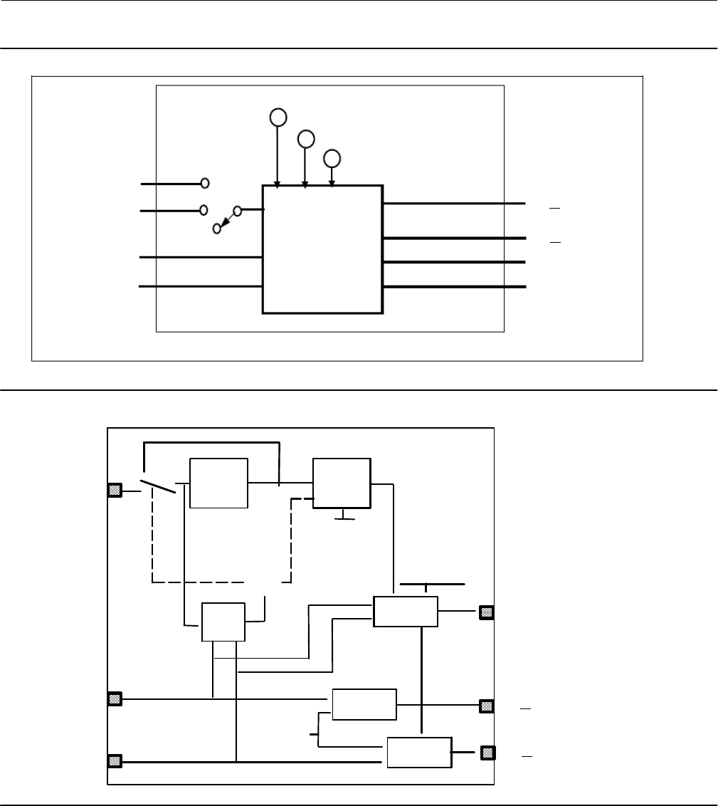
Instruction Manual
D103412X012
Detailed Setup—OS Function Block
January 2015
137
RCAS_IN
OUT 1
CAS_IN
OUT 2
RCAS_OUT
CAS_OUT
BKCAL_IN_2
BKCAL_IN_1
IN_ARRAY
OUT_ARRAY
LOCKVAL
SP
Auto
Figure 4‐17. Output Splitter Function Block Schematic
Figure 4‐18. Output Splitter Function Block Schematic Diagram
Setpoint
Limiting
OUT 1
CAS_IN
OUT 2
BKCAL_OUT
BKCAL_IN_1
IN_ARRAY
BAL_TIME
LOCKVAL
SP
Setpoint
Rate
Limiting
Calculate
Ouput
Balance
Ouput
Balance
Ouput
Shed
Mode
BKCAL_IN_2
MODE
SP_WRK
OUT_ARRAY
SP_RATE_DN
SP_RATE_UP
F
F
F
F
F
"
"
"
F
A
"
A
"
"
"
"
"
"
"
"
"
A
"
A
"
Modes
The Output Splitter function block supports the following actual modes:

Instruction Manual
D103412X012
Detailed Setup—OS Function Block
January 2015
138
Out of Service (OOS)—The block is not processed. FIELD_VAL and PV are not updated and the OUT status is set to
Bad: Out of Service. The BLOCK_ERR parameter shows Out of Service. In this mode, you can make changes to all
configured parameters.
By using permitted mode the target mode of a block may be restricted to one or more of the following modes: Cas,
Auto or OOS.
Note
The output splitter function block must be in Auto for the mode to go to CAS.
Initialization Manual (IMan)—The output path is not complete (for example, the cascade-to-slave path might not be
open). In IMan mode, OUT tracks BKCAL_IN, which allows for bumpless transfer of control.
Automatic (Auto)—The block outputs (OUT_1 and OUT_2) reflect the target operating point specified by the
setpoint (SP) parameter.
Cascade (Cas)—The SP parameter is set by another function block through a connection to CAS_IN. The SP value is
used to set the OUT parameters automatically. This is the most frequently used mode in this block.
The block's normal mode is Cascade (Cas). You can isolate the block for testing by using Automatic (Auto) mode and
adjusting the setpoint.
When a block attached to an output requests initialization, one of the following actions might occur:
When the other output is not in Cas mode, the block attached to the input is initialized.
When the other output is in Cas mode, this output returns to the value calculated from its slope in a specified time
period.
Status Handling
Sub‐status value received at CAS_IN [14] is passed to both outputs, except for those used in the cascade handshake.
An IFS goes to both outputs. The status option IFS if Bad CAS_IN is available.
If the Status Option to Propagate failure is set, the block propagates device failure only if both BKCAL_IN show failed
status. Otherwise the upstream cascade would be broken by a failure at either output.
The statuses of OUT_1 [8] and OUT_2 [9] are determined by the statuses of BKCAL_IN_1 and BKCAL_IN_2 and the
actual mode of the block.
When a BKCAL_IN input sees that its downstream block is not in Cas mode, the Splitter function block sets the
corresponding OUT value to the BKCAL_IN value. However, this may not be the same value that is calculated by the
splitter algorithm. When the mode of the downstream block is changed to Cas, the difference between the calculated
output and the back‐calculation input is computed and the difference is added to the calculated output. Next, the
difference is reduced to zero over the time defined by the BAL_TIME parameter.
When both BKCAL_IN_1 and BKCAL_IN_2 indicate that the downstream blocks are not in Cas mode or have Bad status,
the first downstream block that goes to Cas mode causes the upstream block to initialize so that there is no difference
between the calculated output and the back‐calculation input. This provides bumpless transfer for the first
downstream block.

Instruction Manual
D103412X012
Detailed Setup—OS Function Block
January 2015
139
Limit Handling
The splitter function block is designed to combine the limit information from the two downstream blocks into limits
for the upstream block. The general principle is to allow the upstream block to continue control for as long as possible.
The upstream block is high‐limited (BKCAL_OUT of the Splitter block has high‐limited status) when:
Both downstream blocks are high‐limited (both BKCAL_INS of the Splitter block have high‐limited status)
or
One downstream block is high‐limited, the associated output slope is positive, and the other block has Bad status or
is not in Cas mode
or
One downstream block is low‐limited, the associated output slope is negative, and the other block has Bad status or
is not in Cas mode
or
SP is greater than or equal to X22
The upstream block is low‐limited when:
Both downstream blocks are low‐limited
or
One downstream block is low‐limited, the associated output slope is positive, and the other block has Bad status or
is not in Cas mode
or
One downstream block is high‐limited, the associated output slope is negative, and the other block has Bad status
or is not in Cas mode
or
SP is less than or equal to X11
Input to Output Mapping
The relationship of each output to the input may be defined by a line. Each line may be defined by its endpoints.
Examples of graphical representations of OUT_1 and OUT_2 vs. SP are shown in figure 4‐19 for a split range and a
sequencing application.
The block has the same SP structure as the PID block, except that there is no limiting applied to the SP. The SP may be
used in Auto mode for testing. The operator would use the output of the PID to accomplish the same purpose. Each
downstream block can be taken out of cascade if it becomes necessary to gain control of them.
The examples shown in figure 4‐19 do not show the full range of possibilities. The lines could overlap like an X, or both
start from the origin but have different slopes. The endpoints do not have to lie within 0-100%. Limits in the external
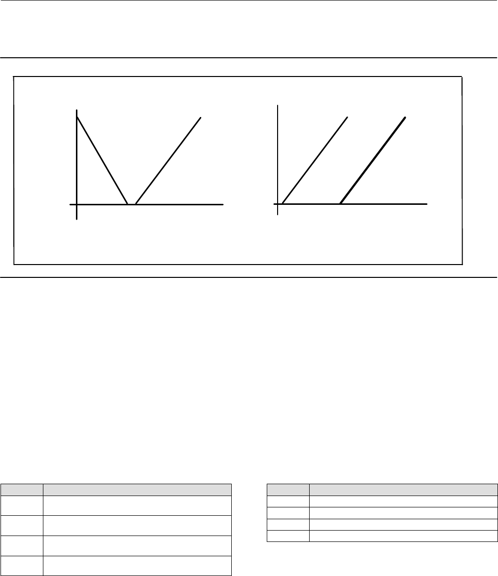
Instruction Manual
D103412X012
Detailed Setup—OS Function Block
January 2015
140
blocks may effect the useful range of a line. Units of percent are used in the examples because the common
application of this block is to valves, but any units may be used to suit the application.
Figure 4‐19. Split Range and Sequence Operation
(X11 , Y11)
SP
Split Range Sequencing
(X22 , Y22)
(X12 , Y12)
OUT_1
OUT_2
0% 50% 100%
100%
100%
OUT_2
OUT_1
100%
0% 0%
0% 50%
(X12 , Y12)(X
22 , Y22)
(X11 , Y11)
(X21 , Y21)(X
21 , Y21)
SP
XX
YY
The following parameters as paired coordinates are used to specify the output splitter operation:
X11, Y11, X12, Y12
X21, Y21, X22, Y22
Where XnJ is the value of SP associated with OUT_n and Xn1 and Xn2 refer to the 1st and 2nd coordinates of the nth
curve respectively. YnJ is the value of OUT_n and Yn1 and Yn2 refer to the 1st and 2nd coordinates of the nth curve
respectively.
By specifying the coordinates as shown in tables 4‐45 and 4‐46, the endpoints of the lines are defined. The contents of
the respective X's are held in the IN_ARRAY parameter and the contents of the respective Y's are held in the
OUT_ARRAY parameter. If a set of points are specified such that a region of the input range is not specified, then the
corresponding OUT_n will be set to the closest endpoint of the input value, either high or low, when the specified
region is exceeded.
Table 4‐45. IN_ARRAY Coordinates
Index Coordinate
0X11 - Start value of SP for the OUT_1 line.
(X11 < X12)
1X12 - End value of SP for the OUT_1 line.
(X11 < X12)
2X21 - Start value of SP for the OUT_2 line.
(X21 < X22)
3X22 - End value of SP for the OUT_2 line.
(X21 < X22)
Table 4‐46. OUT_ARRAY Coordinates
Index Coordinate
0 Y11 - Value of OUT_1 at X11
1 Y12 - Value of OUT_1 at X12
2 Y21 - Value of OUT_2 at X21
3 Y22 - Value of OUT_2 at X22
A configuration error is set in BLOCK_ERR and the actual mode of the block goes to Out of Service if the X values have
any of the following conditions: X21 < X11, X12 < = X11, X22 < = X21.
Refer to figure 4‐20 for an example of LOCKVAL = true, and figure 4‐21 for an example of LOCKVAL = false. The
parameter LOCKVAL provides an option to specify whether OUT_1 remains at its ending level when control is switched
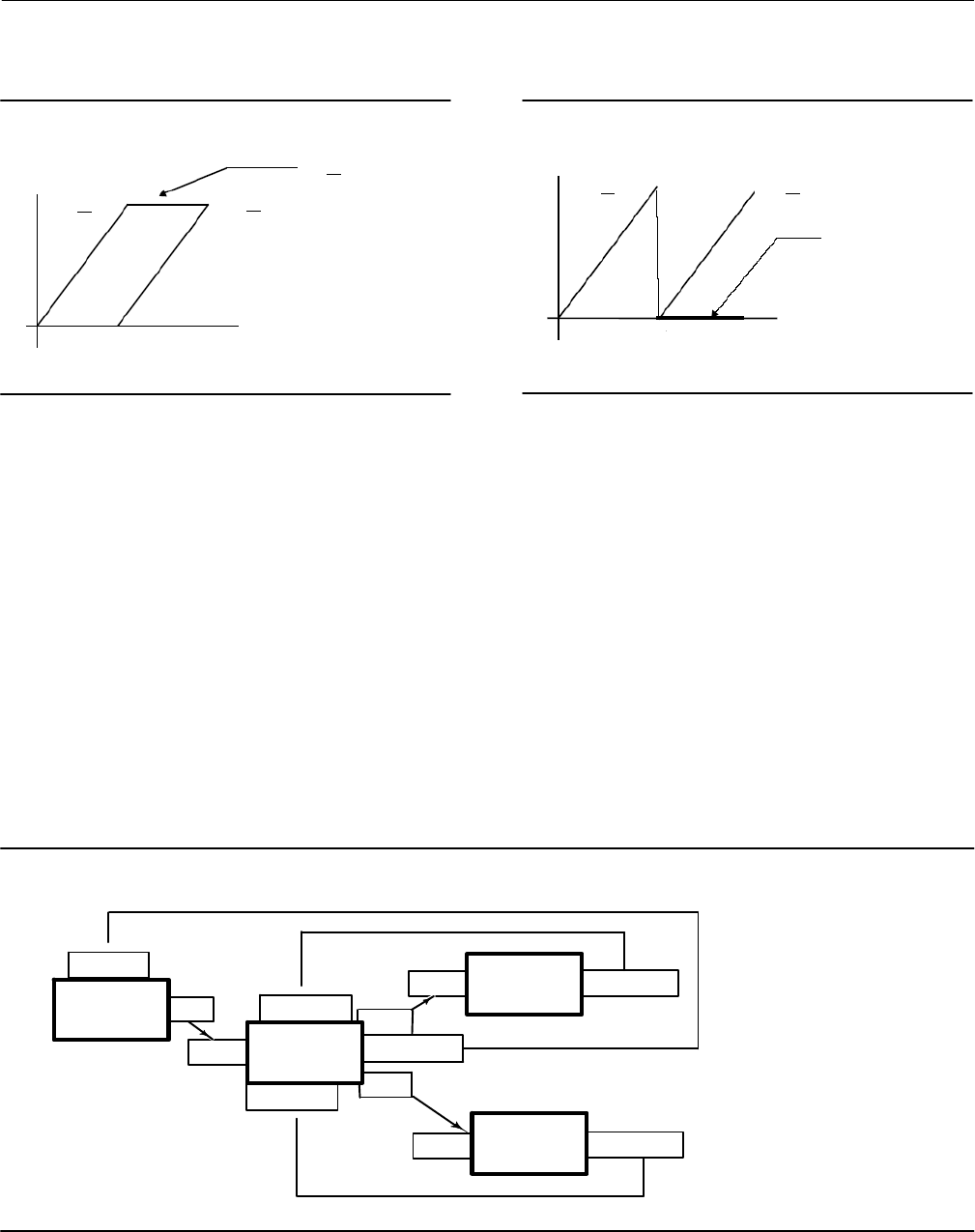
Instruction Manual
D103412X012
Detailed Setup—OS Function Block
January 2015
141
to OUT_2, or goes to Y11. If LOCKVAL is true, OUT_1 remains at its ending value when X is greater than X12. If LOCKVAL
is false, then OUT_1 goes to Y11 when X is greater than X12 .
Figure 4‐20. OUT with LOCKVAL True
0%
SP
OUT 1 OUT 2
OUT 1 remains at
end point when
OUT_2 is non‐zero
50% 100%
Figure 4‐21. OUT with LOCKVAL False
OUT 1 OUT 2
0%
SP
50% 100%
OUT_1 goes to zero
OUT_2 becomes
Some hysteresis in the switching point may be required because the output may change by a full stroke of the valve.
HYSTVAL [12] contains the amount of hysteresis. If X < = X12-HYSTVAL, OUT_1 may be determined by the calculated
y value. If X12-HYSTVAL < X < X12 and X has not reached X12 since it was less than X12-HYSTVAL, OUT_1 may be
determined by the calculated y value. If X12-HYSTVAL < X < X12 and X has reached X12 since it was less than
X12-HYSTVAL, OUT_1 may be determined by the LOCKVAL setting. If X12 < X, OUT_1 may be determined by the
LOCKVAL setting.
Initialization and Back Calculation Requirements
Refer to figure 4‐22, Output Splitter Configuration, where:
PID1 = Upstream driving controller or function block.
Splitter = Split range function block being described.
AO = Receiver of OUT_1 for 0-50% range of SP
PID2 = Receiver of OUT_2 for 50-100% range of SP
Figure 4‐22. Output Splitter Configuration
AO
PID2
PID1
Splitter
BK_CAL_IN
CAS‐IN
OUT
BK_CAL_OUT
BK_CAL_IN2
BK_CAL_IN1
BK_CAL_OUT
BK_CAL_OUT
CAS‐IN
CAS‐IN
OUT2
OUT1

Instruction Manual
D103412X012
Detailed Setup—OS Function Block
January 2015
142
CAS_IN of the Splitter receives the OUT of PID1. BKCAL_IN of PID1 receives BKCAL_OUT of the Splitter. CAS_IN of the
AO receives OUT_1 of the Splitter and PID2 receives OUT_2 of the Splitter. BKCAL_IN_1 of the Splitter receives
BKCAL_OUT of the AO and BKCAL_IN_2 of the Splitter receives BKCAL_OUT of PID2.
The discussion in this section defines the behavior which is used to handle the initial value calculation and status which
can in turn be sent to PID1. This behavior is defined in such a way that no “bumps” are generated by changing modes,
and that PID1 does not wind up.
The splitter utilizes special handling for cascade initialization because it has two independent outputs. When a
downstream block indicates to the splitter that it wants to initialize, by asserting IR (initialization request) on its
BKCAL_OUT, one of two things happens. Under some circumstances, it is possible to pass an initialization request from
a downstream block back up to the block upstream of the splitter, so that all three blocks balance for bumpless
transfer to cascade mode. Otherwise, the requested splitter output goes to the requested value by placing an internal
offset between that output and the output of the curve, and then ramping that offset to zero in BAL_TIME seconds
after the cascade is made up.
The splitter normally runs with both outputs connected to blocks in cascade mode. If one or both of the blocks is not in
cascade mode, special limiting action is taken. Specifically, if one block indicates that it is not in cascade by NI (not
invited) status on its BKCAL_OUT, then the BKCAL_OUT of the splitter asserts limits at the range extremes of the block
that is still in cascade mode. Even if the upstream controller does not want to operate in that range, there will be no
reset windup when it can move into the range. If both downstream blocks show NI, then the splitter can only wait until
one of them requests cascade initialization. BKCAL_OUT of the splitter can hold the upstream block at the value of the
SP. The actual mode is IMan.
When cascade initialization is requested, by IR substatus on a BKCAL_IN, it is first necessary to determine if the other
BKCAL_IN has NI substatus. If so, the value at the BKCAL_IN asserting IR is taken as the Y value for its curve, and the
resulting X value is sent on BKCAL_OUT to PID1. If the other substatus is OK, then the internal offset and BAL_TIME is
used. If both blocks have IR substatus, then one output is processed until its cascade is closed. The choice is based on
the presence of limit status in BKCAL_IN. If BKCAL_IN_1 is limited, then if BKCAL_IN_2 is not limited then OUT_2 is
processed first, else OUT_1 is processed first.
Cascade initialization is also required when the block transitions from Auto to Cas mode. This action is identical to that
described for the PID block.
The required actions are summarized in table 4‐47.
Table 4‐47. OUT_ARRAY Coordinates
BKCAL_IN_1 BKCAL_IN_2 BKCAL_OUT Action
NI NI NI Not Specified
NI OK OK BKCAL_OUT limited to X21 low and X22 high
OK NI OK BKCAL_OUT limited to X11 and X12 high
IR NI IR Initialize cascade to value given by curve X1 vs Y1
IR OK OK Initialize OUT_1 using internal offset from Y1
NI IR IR Initialize cascade to value given by curve X2 vs Y2
OK IR OK Initialize OUT_2 using internal offset from Y2
Note 1: OK means the cascade is closed.
Note 2: Recommend using the average of BKCAL_IN_1 and BKCAL_IN_2, or just SP.
The BKCAL_OUT status shows limited high if an increase in SP cannot be effectively passed on to either output because
the BKCAL_IN_n of both outputs indicates that a move in the needed direction is limited. Similarly, limited low is set if
a decrease in SP cannot be effectively passed on to either output. The slope of the limited line(s) affects the limit
direction. BKCAL_OUT also shows limit status at the X extremes X11 and X22.
Initialization is not automatic under all circumstance because some situations have conflicting needs. In general, when
a control region is in trouble, the upstream controller is limited so it will not drive further into that region. When you
want to move to the other active region, you can put the upstream controller into Man mode and move it, or you can

Instruction Manual
D103412X012
Detailed Setup—OS Function Block
January 2015
143
drop the good downstream block out of Cas mode for one evaluation cycle and then restore Cas mode. This initializes
the upstream controller to the remaining good region of control.
OS Function Block Parameter List (table 4‐48)
Read/Write Capability: RO - Read Only, RW - Read Write
Mode: The block mode(s) required to write to the parameter
Double indentation and shaded Index Number indicates sub‐parameter
Table 4‐48. Output Splitter Function Block Parameter Definitions
Label
PARAMETER_NAME
Index
Number
RO /
RW
Block
Mode Range Initial
Value Description
Static Revision
ST_REV 1 RO N/A 0 to 65535 0
Data Type: Unsigned16
The revision level of the static data associated with the
function block. The revision value will be incremented each
time a static parameter value in the block is changed.
Tag Description
TAG_DESC 2 RW ALL 7 bit ASCII Spaces
Data Type: Octet String
The user description of the intended application of the
block.
Strategy
STRATEGY 3 RW ALL 0 to 65535 0
Data Type: Unsigned 16:
The strategy field can be used to identify grouping of
blocks. This data is not checked or processed by the block.
Alert Key
ALERT_KEY 4 RW ALL 1 to 255 0
Data Type: Unsigned8
The identification number of the plant unit. This information
may be used in the host for sorting alarms, etc.
Block Mode
MODE_BLK 5
Data Type: DS‐69
The actual, target, permitted, and normal modes of the
block.
Target: The requested block mode
Actual: The current mode of the block
Permitted: Allowed modes for Target
Normal: Most common mode for Target
TARGET 5.1 RW
7:OOS
3:AUTO
2:CAS
OOS until
block
configured,
then last
valid target
ACTUAL 5.2 RO OOS
PERMITTED 5.3 RW OOS+AUTO+CAS OOS AUTO
CAS
NORMAL 5.4 RW AUTO+CAS
Block Error
BLOCK_ERR 6 RO N/A
1: Block
Configuration Error
7: Input Failure/Bad
PV Status
8: Output Failure
14: Power‐up
15: Out‐of‐Service
Dynamic
Data Type: Bit String
0=Inactive
1=Active
This parameter reflects the error status associated with the
hardware or software components associated with a block.
It is a bit string, so that multiple errors may be shown.
Setpoint
SP 7PV_SCALE +/- 10% Data Type: DS‐65
Analog setpoint of the block
Output 1
OUT_1 8MAN
OOS
OUT_SCALE
+/- 10%
Data Type: DS‐65
The primary analog output value calculated as a result of
executing the function (the first output value and status).
Output 2
OUT_2 9MAN
OOS
OUT_SCALE
+/- 10%
Data Type: DS‐65
The primary analog output value calculated as a result of
executing the function (the second output value and
status).
Output 1 Range
OUT_1_RANGE 10 RO
EU at 100%
EU at 0 %
Unit Index
Decimal Point
100
0
%
2
Data Type: DS‐68
The high and low scale values, engineering units code, and
number of decimal places to be used in displaying the OUT
value, this parameter has no effect on this block.
-Continued-

Instruction Manual
D103412X012
Detailed Setup—OS Function Block
January 2015
144
Table 4‐48. Output Splitter Function Block Parameter Definitions (Continued)
Description
Initial
Value
Range
Block
Mode
RO /
RW
Index
Number
Label
PARAMETER_NAME
Output 2 Range
OUT_2_RANGE 11 RO
EU at 100%
EU at 0 %
Unit Index
Decimal Point
100
0
%
2
Data Type: DS‐68
The high and low scale values, engineering units code, and
number of decimal places to be used in displaying the OUT
value, this parameter has not effect on this block.
Grant Deny
GRANT_DENY 12 Data Type: DS‐70
Options for controlling access of host computers and local
control panels to operating, tuning, and alarm parameters
of the block. GRANT:0=N/A, 1=granted
DENY: 0=N/A, 1= denied
GRANT 12.1 N/A 0: Program
1: Tune
2: Alarm
3: Local
All bits: 0
DENY 12.2 N/A All bits: 0
Status Options
STATUS_OPTS 13 OOS 1: IFS if BAD CAS_IN All bits: 0
Data Type: Bit String
0=Disabled 1=Enabled
User option for status
Cascade Input
CAS_IN 14 Status
BAD:
NC:
const Data Type: DS‐65
The remote setpoint from another block.
Value 0
Back Calculation Output
BKCAL_OUT 15 RO Status Limits
Data Type: DS‐65
Output value to another block for backwards output
tracking.
Input Array
IN_ARRAY 16 All: 0
Data Type: Float
Used with OUT_ARRAY to map input to output. See Input to
Output Mapping, page 139.
Output Array
OUT_ARRAY 17 All: 0
Data Type: Float
Used with IN_ARRAY to map input to output. See Input to
Output Mapping, page 139.
Lockval
LOCKVAL 18
0=Undfined
1=no lock
2=lock
0=
Undefined
Data Type: Enum
Used with OUT_ARRAY to map input to output. See Input to
Output Mapping, page 139.
Back Calculation Input 1
BKCAL_1_IN 19 Status
BAD:
NC:
const
Data Type: DS‐65
The value and status reflecting the BKCAL_OUT of the lower
block associated with OUT_1. It is used for initialization and
to prevent windup in upstream blocks.
Value 0
Back Calculation Input 2
BKCAL_2_IN 20 Status
BAD:
NC:
const
Data Type: DS‐65
The value and status reflecting the BKCAL_OUT of the lower
block associated with OUT_2. It is used for initialization and
to prevent windup in upstream blocks.
Value 0
Balance Time
BAL_TIME 21 Positive 0
Data Type: Float
Specifies the time for the internal working value of bias or
ratio to return to the operator set bias or ratio, in seconds.
Hystval
HYSTVAL 22
Update Event
UPDATE_EVT 23 RO N/A
Data Type: DS‐73
This alert is generated by any change to the static data.
UNACKNOWLEDGED 23.1 RW N/A
0=Undefined
1=Acknowledged
2=Unacknowledged
0=
Undefined
UPDATE STATE 23.2 RO N/A
0=Undefined
1=Update Reported
2=Updated not
reported
0=
Undefined
TIME_STAMP 23.3 RO N/A 0
STATIC_REVISION 23.4 RO N/A 0
RELATIVE_INDEX 23.5 RO N/A 0
-Continued-
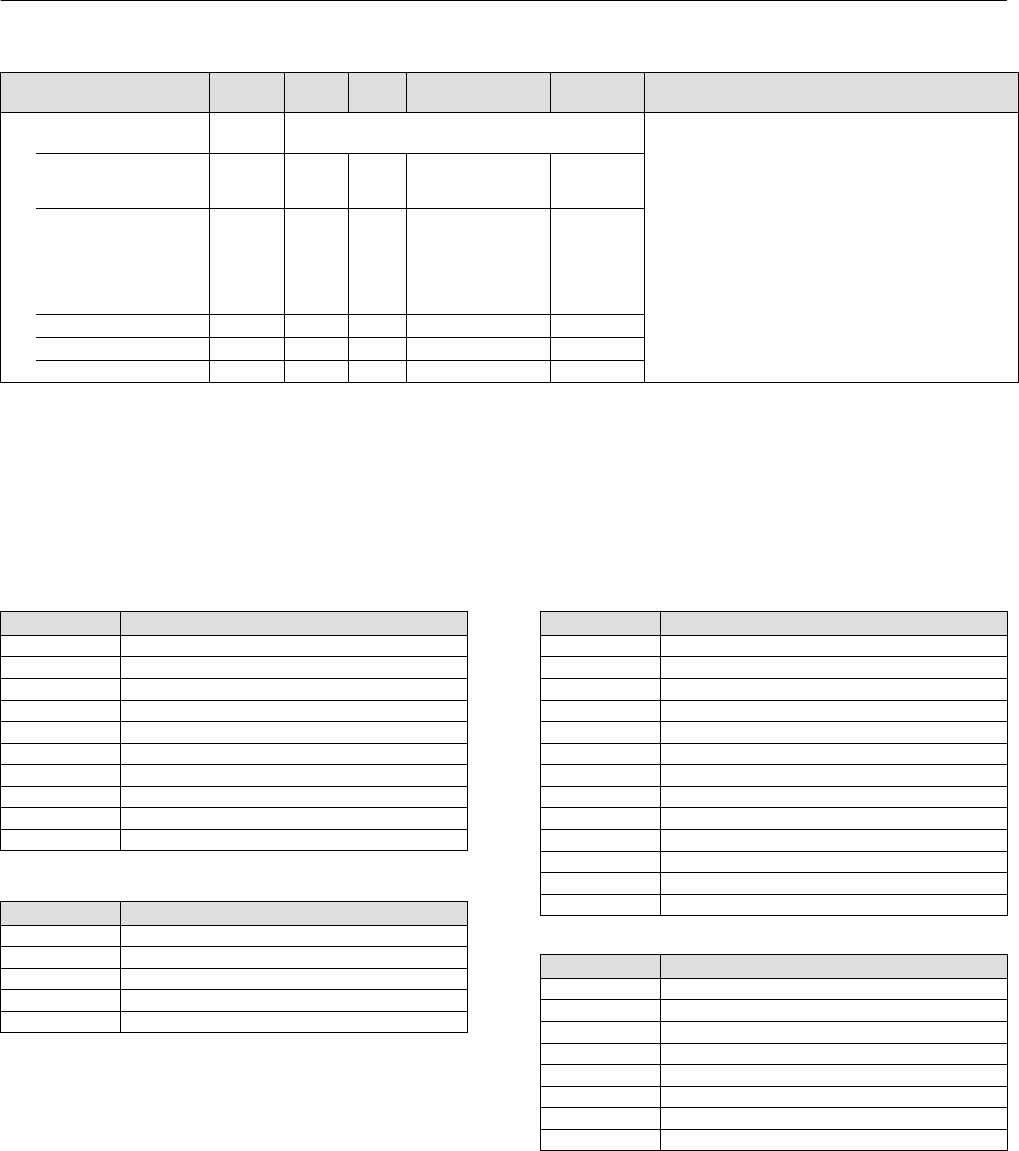
Instruction Manual
D103412X012
Detailed Setup—OS Function Block
January 2015
145
Table 4‐48. Output Splitter Function Block Parameter Definitions (Continued)
Description
Initial
Value
Range
Block
Mode
RO /
RW
Index
Number
Label
PARAMETER_NAME
Block Alarm
BLOCK_ALM 24
Data Type: DS‐72
The block alarm is used for all configuration, hardware,
connection failure, or system problems in the block. The
cause of the alert is entered in the subcode field.
UNACKNOWLEDGED 24.1 RW N/A
0: Undefined
1: Acknowledged
2: Unacknowledged
ALARM_STATE 24.2 RO N/A
0: Undefined
1: Clear reported
2: Clear not reported
3: Active reported
4: Active not
reported
TIME_STAMP 24.3 RO N/A
SUBCODE 24.4 RO N/A
VALUE 24.5 RO N/A
View Lists
View lists allow the values of a set of parameters to be accessed at the same time. Views 1 and 2 contain operating
parameters and are defined by the Fieldbus Foundation. View 3 contains dynamic parameters and View 4 contains
static parameters with configuration and maintenance information. Views 3 and 4 are defined by the manufacturer.
Table 4‐49. OS Function Block, View 1
Index Number Parameter
1 ST_REV
5.1 MODE_BLK.TARGET_MODE
5.2 MODE_BLK.ACTUAL_MODE
5.3 MODE_BLK.PERMITTED_MODE
5.4 MODE_BLK.NORMAL_MODE
6 BLOCK_ERR
7 SP
8 OUT_1
9 OUT_2
14 CAS_IN
Table 4‐50. OS Function Block, View 2
Index Number Parameter
1 ST_REV
10 OUT_1_RANGE
11 OUT_2_RANGE
12.1 GRANT_DENY.GRANT
12.2 GRANT_DENY.DENY
Table 4‐51. OS Function Block, View 3
Index Number Parameter
1 ST_REV
5.1 MODE_BLK.TARGET_MODE
5.2 MODE_BLK.ACTUAL_MODE
5.3 MODE_BLK.PERMITTED_MODE
5.4 MODE_BLK.NORMAL_MODE
6 BLOCK_ERR
7 SP
8 OUT_1
9 OUT_2
14 CAS_IN
15 BKCAL_OUT
19 BKCAL_1_IN
20 BKCAL_2_IN
Table 4‐52. OS Function Block, View 4
Index Number Parameter
1 ST_REV
3 STRATEGY
4 ALERT_KEY
13 STATUS_OPTS
16 IN_ARRAY
17 OUT_ARRAY
18 LOCKVAL
21 BAL_TIME

Instruction Manual
D103412X012
Detailed Setup—OS Function Block
January 2015
146
OUTPUT SPLITTER FUNCTION BLOCK
Field Communicator Menu Structure
All
Characteristics
Static Revision
Tag Description
Strategy
Alert Key
Block Mode: Target
Block Mode: Actual
Block Mode: Permitted
Block Mode: Normal
Block Error
Setpoint: Status
Setpoint: Value
Output 1: Status
Output 1: Value
Output 2: Status
Output 2: Value
Output 1 Range: EU at 100%
Output 1 Range: EU at 0%
Output 1 Range: Units Index
Output 1 Range: Decimal
Output 2 Range: EU at 100%
Output 2 Range: EU at 0%
Output 2 Range: Units Index
Output 2 Range: Decimal
Grant Deny: Grant
Grant Deny: Deny
Status Options
Cascade Input: Status
Cascade Input: Value
Back Calculation Output: Status
Back Calculation Output: Value
Input Array[1]
Input Array[2]
Input Array[3]
Input Array[4]
Output Array[1]
Output Array[2]
Output Array[3]
Output Array[4]
Lockval
Back Calculation Input 1: Status
Back Calculation Input 1: Value
Back Calculation Input 2: Status
Back Calculation Input 2: Value
Balance Time
Hystval
Update Event: Unacknowledged
Update Event: Update State
Update Event: Time Stamp
Update Event: Static Rev
Update Event: Relative Index
Block Alarm: Unacknowledged
Block Alarm: Alarm State
Block Alarm: Time Stamp
Block Alarm: Subcode
Block Alarm: Value

Instruction Manual
D103412X012
Detailed Setup—AI Function Block
January 2015
147
Analog Input Function Block
Overview
The Analog Input (AI) function block (figure 4‐23) processes field device measurements and makes them available to
other function blocks. The output value from the AI block is in engineering units and contains a status indicating the
quality of the measurement. The measuring device may have several measurements or derived values available in
different channels. Use the channel number to define the variable that the AI block processes.
Figure 4‐23. Analog Input (AI) Function Block
OUT_D
OUT
OUT
OUT_D
= THE BLOCK OUTPUT VALUE AND STATUS
= DISCRETE OUTPUT THAT SIGNALS A SELECTED
ALARM CONDITION
FIELDBUS‐FBUS_31A
The AI block supports alarming, signal scaling, signal filtering, signal status calculation, mode control, and simulation.
In Automatic mode, the block's output parameter (OUT [8]) reflects the process variable (PV [7]) value and status. In
Manual mode, OUT [8] may be set manually. The Manual mode is reflected on the output status. A discrete output
(OUT_D [37]) is provided to indicate whether a selected alarm condition is active. Alarm detection is based on the OUT
[8] value and user specified alarm limits. Figure 4‐24 illustrates the internal components of the AI function block, and
table 4‐57 lists the AI block parameters and their units of measure, descriptions, and index numbers.
Modes
The AI function block supports three modes of operation as defined by the MODE_BLK [5] parameter:
Manual (Man) The block output (OUT [8]) may be set manually.
Automatic (Auto) OUT reflects the analog input measurement or the simulated value when simulation is enabled.
Out of Service (OOS) The block is not processed. FIELD_VAL [19] and PV [7] are not updated and the OUT [8] status
is set to Bad: Out of Service. The BLOCK_ERR [6] parameter shows Out of Service. In this mode, you can make
changes to all configured parameters. The target mode of a block may be restricted to one or more of the
supported modes.
Alarm Detection
A block alarm will be generated whenever the BLOCK_ERR [6] has an error bit set. The types of block errors for the AI
block are defined in table 4‐55.
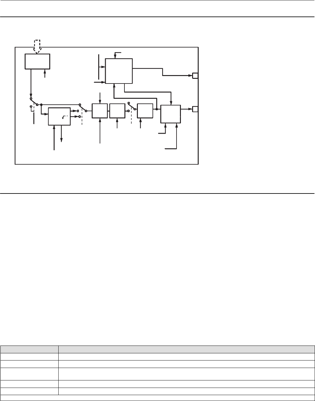
Instruction Manual
D103412X012
Detailed Setup—AI Function Block
January 2015
148
Figure 4‐24. Analog Input Function Block Schematic
ANALOG
MEASUREMENT
ACCESS
ANALOG
MEAS.
CHANNEL
SIMULATE
CONVERT STATUS
CALC.
OUT_D
OUT
PV
ALARM
DETECTION
ALARM_TYPE
ALARM_HYS
LOW_CUT
HI_HI_LIM
HI_LIM
LO_LO_LIM
LO_LIM
OUT_SCALE
XD_SCALE
FIELD_VAL IO_OPTS STATUS_OPTS
CUTOFF FILTER
PV_FTIME
L_TYPE
MODE
NOTES:
OUT_D = BLOCK OUTPUT VALUE AND STATUS
OUT_D = DISCRETE OUTPUT THAT SIGNALS A SELECTED ALARM CONDITION.
FIELDBUS‐FBUS_02A
Process Alarm detection is based on the OUT [8] value. You can configure the alarm limits of the following standard
alarms:
High (HI_LIM [28])
High high (HI_HI_LIM [26])
Low (LO_LIM [30])
Low low (LO_LO_LIM [32])
In order to avoid alarm chattering when the variable is oscillating around the alarm limit, an alarm hysteresis in percent
of the PV [7] span can be set using the ALARM_HYS [24] parameter. The priority of each alarm is set in the following
parameters:
HI_PRI [27]
HI_HI_PRI [25]
LO_PRI [29]
LO_LO_PRI [31]
Alarms are grouped into five levels of priority, as shown in table 4‐53.
Table 4‐53. AI Function Block Alarm Priorities
Priority Number Priority Description(1)
0The priority of an alarm condition changes to 0 after the condition that caused the alarm is corrected.
1An alarm condition with a priority of 1 is recognized by the system, but is not reported to the operator.
2An alarm condition with a priority of 2 is reported to the operator, but generally does not require operator attention (such as
diagnostics and system alerts).
3-7 Alarm conditions of priority 3 to 7 are advisory alarms of increasing priority.
8-15 Alarm conditions of priority 8 to 15 are critical alarms of increasing priority.
1. The priority classes “advise” and “critical” have no relationship to PlantWeb Alerts.
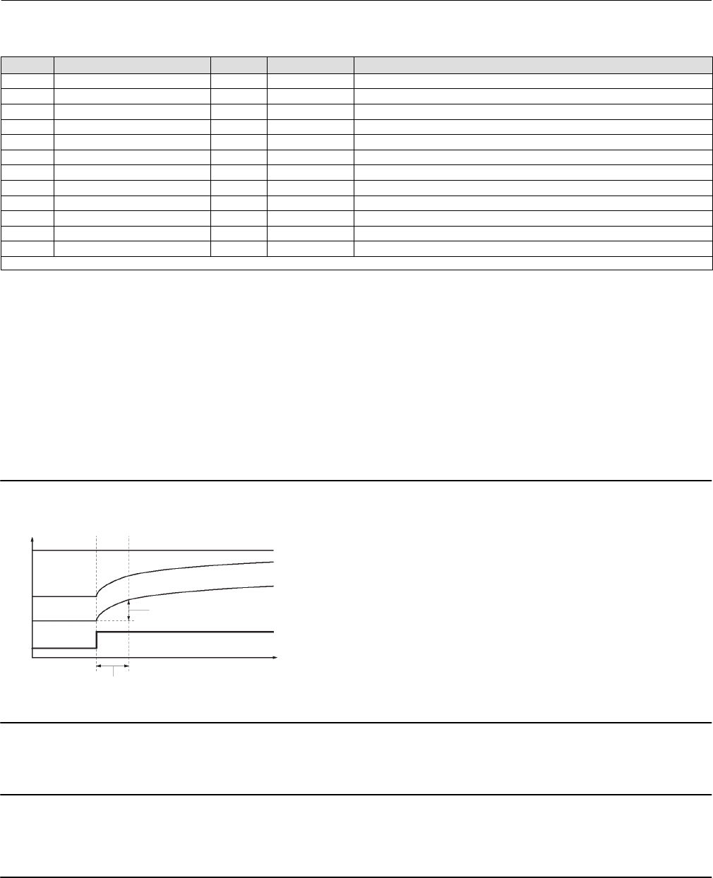
Instruction Manual
D103412X012
Detailed Setup—AI Function Block
January 2015
149
Table 4‐54. Channel Selections for the Analog Input Function Block
Channel Parameter(1) Block Index Number XD_SCALE Units
2 TRAVEL_TARGET TB 49 % (1342)
3 FINAL_POSITION_VALUE TB 17 % (1342)
4 TRAVEL TB 34 % (1342)
5 SUPPLY_PRESS TB 35 psig (1143), bar (1137), kPa (1133), inHg (1155), inH20 (1146), kg/cm2 (1145)
6 PRESSURE_A TB 36 psig (1143), bar (1137), kPa (1133), inHg (1155), inH20 (1146), kg/cm2 (1145)
7 PRESSURE_B TB 37 psig (1143), bar (1137), kPa (1133), inHg (1155), inH20 (1146), kg/cm2 (1145)
8 PRESSURE_DIFF TB 38 psig (1143), bar (1137), kPa (1133), inHg (1155), inH20 (1146), kg/cm2 (1145)
9 DRIVE_SIGNAL TB 53 % (1342)
10 TRAVEL_DEVIATION TB 52 % (1342)
11 TEMPERATURE TB 48 C (1001), F (1002)
12 CYCLE_COUNT TB 73 no units (1588)
13 TRAVEL_ACCUMULATION TB 72 % (1342)
1. Refer to table 4‐14 for transducer block parameter descriptions and table 4‐25 for AO parameter descriptions.
Status Handling
The AI block only gets Good Non‐Specified Unlimited or Bad Device Failure for status from the transducer. This is
reflected in FIELD_VAL.STATUS [19.1]. PV.STATUS [7.1] is the same as FIELD_VAL.STATUS [19.1]. OUT.STATUS [8.1]
can also reflect Bad, Out of Service in addition to PV.STATUS [7.1] values.
In the STATUS_OPTS [14] parameter, you can select from the following options to control the status handling:
Propagate Fail Forward—If the status from the sensor is Bad, Device failure or Bad, Sensor failure, propogate it to OUT
without generating an alarm. The use of these sub‐status in OUT is determined by this option. Through this option,
you may determine whether alarming (sending out an alert) will be done by the block or propagated downstream for
alarming.
Figure 4‐25. Analog Input Function Block Timing Diagram
OUT (mode in man)
OUT (mode in auto)
PV
63% of Change
TIME (seconds)
FIELD_VAL
PV_FTIME
FIELDBUS‐FBUS_03A
Uncertain if in Manual mode—The status of the Output is set to Uncertain when the mode is set to Manual.
Note
1. The instrument must be in Out of Service mode to set the status option.
2. The AI block only supports the Uncertain if in Manual and Propagate failure. Unsupported options are not grayed out; they
appear on the screen in the same manner as supported options.

Instruction Manual
D103412X012
Detailed Setup—AI Function Block
January 2015
150
Filtering
The filtering feature changes the response time of the device to smooth variations in output readings caused by rapid
changes in input. You can adjust the filter time constant (in seconds) using the PV_FTIME [18] parameter. Set the filter
time constant to zero to disable the filter feature.
Signal Conversion
You can set the signal conversion type with the Linearization Type (L_TYPE [16]) parameter. You can view the
converted signal (in percent of XD_SCALE [10]) through the FIELD_VAL [19] parameter.
100 X (Channel Value) - EU *@0%
FIELD_VAL =
(EU *@100% - EU *@0%)
*XD_SCALE values
You can choose from direct, indirect, or indirect square root signal conversion with the L_TYPE [16] parameter.
Direct
Direct signal conversion allows the signal to pass through the accessed channel input value (or the simulated value
when simulation is enabled).
PV = Channel Value
Indirect
Indirect signal conversion converts the signal linearly to the accessed channel input value (or the simulated value when
simulation is enabled) from its specified range (XD_SCALE [10]) to the range and units of the PV [7] and OUT [8]
parameters (OUT_SCALE [11]).
X (EU **@100% - EU **@0%) + EU **@0%
**OUT_SCALE values
PV = 100
()
FIELD_VAL
Indirect Square Root
Indirect Square Root signal conversion takes the square root of the value computed with the indirect signal conversion
and scales it to the range and units of the PV [7] and OUT [8] parameters.
PV = FIELD_VAL X (EU **@100% - EU **@0%) + EU **@0%
100 )
(
**OUT_SCALE values

Instruction Manual
D103412X012
Detailed Setup—AI Function Block
January 2015
151
When the converted input value is below the limit specified by the LOW_CUT [17] parameter, a value of zero is used
for the converted value (PV [7]). This option is useful to eliminate false readings when the differential pressure
measurement is close to zero.
Note
Invert is the only I/O option supported by the AI block. You can set the I/O option in Out of Service mode only.
Advanced Features
The AI function block provided with the DVC6200f provides added capability through the addition of the following
parameters:
ALARM_SEL—Allows one or more of the process alarm conditions detected by the AI function block to be used in
setting its OUT_D [37] parameter.
OUT_D—Discrete output of the AI function block based on the detection of process alarm condition(s). This parameter
may be linked to other function blocks that require a discrete input based on the detected alarm condition.
STDDEV and CAP_STDDEV— are diagnostic parameters that can be used to determine the variability of the process.
Simulation
To support testing, you can either change the mode of the block to manual and adjust the output value, or you can
enable simulation through the configuration tool and manually enter a value for the measurement value and its status.
To enable simulation, you must first install the Simulate Enable jumper across the instrument AUX terminals (see page
13). Next you must use the configuration tool to enable the parameter SIMULATE [9].
With simulation enabled, the actual measurement value has no impact on the OUT [8] value or the status.
Block Errors
Table 4‐55 lists conditions reported in the BLOCK_ERR [6] parameter. Conditions in italics are inactive for the AI block
and are given here only for your reference.
Table 4‐55. BLOCK_ERR Conditions
Condition Number Condition Name and Description
0Other
1Block Configuration Error ‐ the selected channel carries a measurement that is incompatible with the engineering units
selected in XD_SCALE, the L_TYPE parameter is not configured, or CHANNEL = zero.
2Link Configuration Error
3Simulate Active ‐ Simulation is enabled and the block is using a simulated value in its execution.
4Local Override
5Device Fault State
6Device Needs Maintenance Soon
7Input failure/process variable had Bad status ‐ The hardware is bad, or a bad status is being simulated
8Output failure
9Memory failure
10 Lost Static Data
11 Lost NV Data
12 Readback Check Failed
13 Device Needs Maintenance Now
14 Power Up - This condition exists until the AI function block executes for the first time.
15 Out of Service ‐ The actual mode is Out of Service.

Instruction Manual
D103412X012
Detailed Setup—AI Function Block
January 2015
152
Troubleshooting
Refer to table 4‐56 to troubleshoot any problem that you encounter.
Table 4‐56. Troubleshooting
Symptom Possible Causes Corrective Action
Mode will not leave OOS Target mode is not set Set target mode to something other than OOS
Configuration error
BLOCK_ERR [6] will show the configuration error bit set. The
following are parameters that must be set before the block is
allowed out of OOS:
CHANNEL [15] must be set to a valid value and cannot be
left at initial value of 0.
XD_SCALE [10]. UNITS_INDEX must match the units in the
transducer block channel value.
L_TYPE [16] must be set to Direct, Indirect, or Indirect
Square Root and cannot be left at an initial value of 0.
Resource block The actual mode of the Resource block is OOS. See Resource
Block Diagnostics for corrective action.
Schedule Block is not scheduled and therefore cannot execute to go to
Target Mode. Schedule the block to execute.
Process and/or block alarms will not work Features FEATURES_SEL [18] in the resource block does not have Alerts
enabled. Enable the Reports Supported bit.
Notification LIM_NOTIFY [32] in the resource block is not high enough. Set
equal to MAX_NOTIFY [31], also in the resource block.
Status Options STATUS_OPTS [14] has Propagate Fault Forward bit set. This
should be cleared to cause an alarm to occur.
Value of output does not make sense Linearization Type L_TYPE [16] must be set to Direct, Indirect, or Indirect Square
Root and cannot be left at an initial value of 0.
Scaling
Scaling parameters are set incorrectly:
XD_SCALE.EU0 and EU100 should match that of the trans
ducer block channel value.
OUT_SCALE.EU0 and EU100 are not set properly.
Cannot set HI_LIMIT [28], HI_HI_LIMIT [26],
LO_LIMIT [30], or LO_LO_LIMIT [32] VALUES Scaling
Limit values are outside the OUT_SCALE.EU0 and
OUT_SCALE.EU100 values. Change OUT_SCALE [11] or set
values within range.
AI Function Block Parameter List (table 4‐57)
Read/Write Capability: RO - Read Only, RW - Read Write
Mode: The block mode(s) required to write to the parameter
Double indentation and shaded Index Number indicates sub‐parameter

Instruction Manual
D103412X012
Detailed Setup—AI Function Block
January 2015
153
Table 4‐57. Analog Input Block Parameter Definitions
Label
PARAMETER_NAME
Index
Number
RO /
RW
Write Block
Mode Range Initial
Value Description
Static Revision
ST_REV 1 RO N/A 0 to 65535 0
Data Type: Unsigned16
The revision level of the static data associated with
the function block. The revision value will be
incremented each time a static parameter value in
the block is changed
Tag Description
TAG_DESC 2 ALL 7 bit ASCII spaces
Data Type: Octet String
The user description of the intended application of
the block.
Strategy
STRATEGY 3 ALL 0 to 65535 0
Data Type: Unsigned16
The strategy field can be used to identify grouping
of blocks. This data is not checked or processed by
the block.
Alert Key
ALERT_KEY 4 ALL 1 to 255 0
Data Type: Unsigned8
The identification number of the plant unit. This
information may be used in the host for sorting
alarms, etc.
Block Mode
MODE_BLK 5
Data Type: DS‐69
Valid Bits: 7: OOS, 4: MAN, 3: AUTO
The actual, target, permitted, and normal modes of
the block.
Target: The requested block mode
Actual: The current mode of the block
Permitted: Allowed modes for Target
Normal: Most common mode for Target
TARGET 5.1 RW ALL
OOS
MAN
AUTO
OOS until block
is configured,
then last valid
target
ACTUAL 5.2 RO ALL OOS
PERMITTED 5.3 RW ALL OOS+MAN+AUTO OOS, MAN,
AUTO
NORMAL 5.4 RW ALL AUTO
Block Error
BLOCK_ERR 6 RO
1: Block Configuration
Error
3: Simulate Active
7: Input Failure/ Bad PV
Status
14: Power‐up
15: Out‐of‐Service
Data Type: Bit String
0=Inactive
1=Active
Error status associated with the hardware or
software for the AI block.
Process Value
PV 7 RO PV Status set equal to
FIELDV_VAL Status
Data Type: DS‐65
Reflects the scaled value from the configured
channel. Units set by OUT_SCALE and L_TYPE.
Primary Output
OUT 8OOS, MAN OUT_STATE Data Type: DS‐68
The block output value and status.
Simulate
SIMULATE 9
Data Type: DS‐82
A group of data that contains the current transducer
value and status, the simulated transducer value
and status, and the enable/disable bit.
SIMULATE_STATUS 9.1 ALL 0
SIMULATE_VALUE 9.2 ALL 0
TRANSDUCER_STATUS 9.3 RO 0
TRANSDUCER_VALUE 9.4 RO 0
ENABLE/DISABLE 9.5 ALL
0=Not Initialized
1=Simulation Disabled
2=Simulation Active
1=simulate
disabled
Transducer Scale
XD_SCALE 10 OOS
EU at 100%
EU at 10%
Units Index
Decimal Point
100
0
%
2
Data Type: DS‐68
Transducer scaling (XD_SCALE) is applied to the
value from the channel to produce the FIELD_VAL in
percent. The XD_SCALE units code must match the
channel units code (if one exists), or the block will
remain in OOS mode after being configured.
Output Scale
OUT_SCALE 11 OOS
EU at 100%
EU at 10%
Units Index
Decimal Point
100
0
%
2
Data Type: DS‐68
The high and low scale values, engineering units
code, and number of decimal places to be used in
displaying the OUT parameter and parameters
which have the same scaling as OUT.
-Continued-

Instruction Manual
D103412X012
Detailed Setup—AI Function Block
January 2015
154
Table 4‐57. Analog Input Block Parameter Definitions (Continued)
Description
Initial
Value
Range
Write Block
Mode
RO /
RW
Index
Number
Label
PARAMETER_NAME
Grant Deny
GRANT_DENY 12 Data Type: DS‐70
Options for controlling access of host computer and
local control panels to operating, tuning, and alarm
parameters of the block.
GRANT: 0=N/A, 1=granted
DENY: 0=N/A, 1=denied
GRANT 12.1 ALL Valid Bits
0: Program
1: Tune
2: Alarm
3: Local
All bits: 0
DENY 12.2 ALL All bits: 0
I/O Options
IO_OPTS 13 OOS 10: Low cutoff All bits: 0
Data Type: Bit String
0=Disable
1=Enable
User options for Output Control.
Status Options
STATUS_OPTS 14 OOS
3: Propagate Failure
forward
6: Uncertain if Limited
7: Bad if Limited
8: Uncertain in Man
Mode
All bits: 0
Data Type: Bit String
0=Disable
1=Enable
User options for Status
AI Channel
CHANNEL 15 OOS See table 4‐54 0: Undefined
Data Type: Unsigned16
Used to select the type of threshold that is used to
set the output.
Linearization Type
L_TYPE 16 OOS, MAN
0: Undefined
1: Direct
2: Indirect
3: Ind. Sqr. Root
0: Undefined
Data Type: Enum
Linearization type. Determines whether the field
value is used directly (Direct), is converted linearly
(Indirect), or is converted with the square root
(Indirect Square Root). The OUT_SCALE is normally
the same as the transducer, but if L_TYPE is set to
Indirect or Ind Sqr Root, OUT_SCALE determines the
conversion from FIELD_VAL to the output.
Low Cutoff
LOW_CUT 17 ALL Positive 0
Data Type: Float
If calculated output is below this value the output is
0.
Process Value Filter Time
PV_FTIME 18 ALL Positive 0 Data Type: Float
Time constant of first order filter on PV, in seconds.
Field Value
FIELD_VAL 19 RO 0
Data Type: DS‐65
Value of the field device analog input, with a status
reflecting the Transducer condition.
Updated Event
UPDATE_EVT 20
Data Type: DS‐73
This alarm is generated whenever a static parameter
is changed.
UNACKNOWLEDGED 20.1 RW N/A
0=Undefined
1=Acknowledged
2=Unacknowledged
0=Undefined
UPDATE_STATE 20.2 RO N/A
0=Undefined
1=Update reported
2=Update not reported
0=Undefined
TIME_STAMP 20.3 RO N/A 0
STATIC_REVISION 20.4 RO N/A 0
RELATIVE_INDEX 20.5 RO N/A 0
Block Alarm
BLOCK_ALM 21
Data Type: DS‐72
The block alarm is used for all configuration,
hardware, connection failure or system problems in
the block. The cause of the alert is entered in the
subcode field.
UNACKNOWLEDGED 21.1 RW
0=Undefined
1=Acknowledged
2=Unacknowledged
ALARM_STATE 21.2 RO
0=Undefined
1=Clear‐reported
2=Clear‐not reported
3=Active‐reported
4=Active‐not reported
TIME_STAMP 21.3 RO
SUBCODE 21.4 RO
VALUE 21.5 RO
-Continued-

Instruction Manual
D103412X012
Detailed Setup—AI Function Block
January 2015
155
Table 4‐57. Analog Input Block Parameter Definitions (Continued)
Description
Initial
Value
Range
Write Block
Mode
RO /
RW
Index
Number
Label
PARAMETER_NAME
Alarm Summary
ALARM_SUM 22 Data Type: DS‐74 Current alert status,
unacknowledged states, unreported states, and
disabled states of the alarms associated with the
function block.
0=clear
0=acknowledged
0=reported
0=enabled
CURRENT 22.1 RO ALL 0: Discrete alarm
1: Hi Hi alarm
2: Hi Alarm
3: Lo Lo Alarm
4: Lo Alarm
7: Block alarm
UNACKNOWLEDGED 22.2 RO ALL
UNREPORTED 22.3 RO ALL
DISABLED 22.4 RW ALL All bits: 0
Acknowledge Option
ACK_OPTION 23 ALL
0: Discrete alarm
1: Hi Hi alarm
2: Hi Alarm
3: Lo Lo Alarm
4: Lo Alarm
7: Block alarm
All bits: 0
Data Type: Bit String
0=Disable
1=Enable
Selection of whether alarms associated with the
block will be automatically acknowledged.
Alarm Hysteresis
ALARM_HYS 24 ALL 0 - 50% 0.50% Data Type: Float
Hysteresis on alarms.
High High Priority
HI_HI_PRI 25 ALL 0 to 15 0Data Type: Unsigned8
The priority of the hi hi alarm.
High High Limit
HI_HI_LIM 26 ALL OUT_SCALE 0 Data Type: Float
Value of analog input which will generate an alarm.
High Priority
HI_PRI 27 ALL 0 to 15 0Data Type: Unsigned8
The priority of the high alarm.
Hi Limit
HI_LIM 28 ALL OUT_SCALE 0 Data Type: Float
Value of analog input which will generate an alarm.
Low Priority
LO_PRI 29 ALL 0 to 15 0Data Type: Unsigned8
The priority of the low alarm.
Low Limit
LO_LIM 30 ALL OUT_SCALE 0 Data Type: Float
Value of analog input which will generate an alarm.
Low Low Priority
LO_LO_PRI 31 ALL 0 to 15 0Data Type: Unsigned8
The priority of the low low alarm.
Low Low Limit
LO_LO_LIM 32 ALL OUT_SCALE 0 Data Type: Float
Value of analog input which will generate an alarm.
High High Alarm
HI_HI_ALM 33
Data Type: DS‐71
The status of the hi hi alarm and its associated time
stamp.
UNACKNOWLEDGED 33.1 RW
N/A
0
ALARM_STATE 33.2 RO 0
TIME_STAMP 33.3 RO 0
SUBCODE 33.4 RO 0
VALUE 33.5 RO 0
High Alarm
HI_ALM 34
Data Type: DS‐71
The status of the hi alarm and its associated time
stamp.
UNACKNOWLEDGED 34.1 RW
N/A
0
ALARM_STATE 34.2 RO 0
TIME_STAMP 34.3 RO 0
SUBCODE 34.4 RO 0
VALUE 34.5 RO 0
Low Alarm
LO_ALM 35
Data Type: DS‐71
The status of the lo alarm and its associated time
stamp.
UNACKNOWLEDGED 35.1 RW
N/A
0
ALARM_STATE 35.2 RO 0
TIME_STAMP 35.3 RO 0
SUBCODE 35.4 RO 0
VALUE 35.5 RO 0
-Continued-
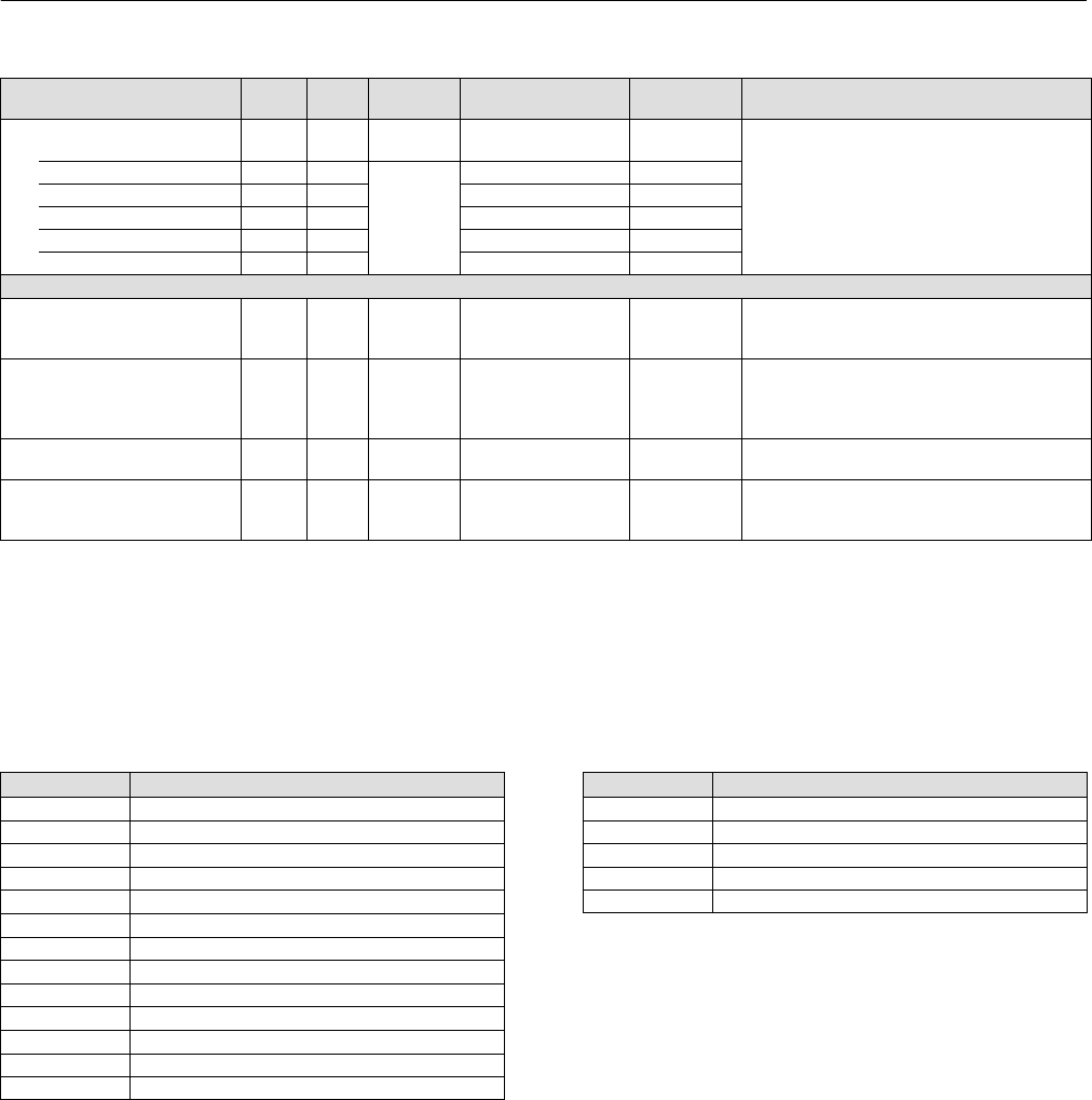
Instruction Manual
D103412X012
Detailed Setup—AI Function Block
January 2015
156
Table 4‐57. Analog Input Block Parameter Definitions (Continued)
Description
Initial
Value
Range
Write Block
Mode
RO /
RW
Index
Number
Label
PARAMETER_NAME
Low Low Alarm
LO_LO_ALM 36
Data Type: DS‐71
The status of the lo lo alarm and its associated time
stamp.
UNACKNOWLEDGED 36.1 RW
N/A
0
ALARM_STATE 36.2 RO 0
TIME_STAMP 36.3 RO 0
SUBCODE 36.4 RO 0
VALUE 36.5 RO 0
Extended Parameter
Output Discrete
OUT_D 37 OOS, MAN OUT_STATE
Data Type: DS‐66
Discrete Output this is true (1) if any of the alarms
selected in ALM_SEL are active.
Alarm Select
ALM_SEL 38 ALL
1: Hi Hi alarm
2: Hi Alarm
3: Lo Lo Alarm
4: Lo Alarm
All bits: 0
Data Type: Bitstring
0=unselected
1=selected
Selected alarms that activate the alarm output.
StdDev
STDDEV 39 RO N/A Positive float Data Type: Float
Standard deviation of the measurement.
Cap StdDev
CAP_STDDEV 40 RO N/A Positive float
Data Type: Float
Capability standard deviation, the best deviation
that can be achieved.
View Lists
View lists allow the values of a set of parameters to be accessed at the same time. Views 1 and 2 contain operating
parameters and are defined by the Fieldbus Foundation. View 3 contains dynamic parameters and View 4 contains
static parameters with configuration and maintenance information. Views 3 and 4 are defined by the manufacturer.
Table 4‐58. AI Function Block, View 1
Index Number Parameter
1 ST_REV
5.1 MODE_BLK.TARGET_MODE
5.2 MODE_BLK.ACTUAL_MODE
5.3 MODE_BLK.PERMITTED_MODE
5.4 MODE_BLK.NORMAL_MODE
6 BLOCK_ERR
7 PV
8 OUT
19 FIELD_VAL
22.1 ALARM_SUM.CURRENT
22.2 ALARM_SUM.UNACKNOWLEDGED
22.3 ALARM_SUM.UNREPORTED
22.4 ALARM_SUM.DISABLED
Table 4‐59. AI Function Block, View 2
Index Number Parameter
1 ST_REV
10 XD_SCALE
11 OUT_SCALE
12.1 GRANT_DENY.GRANT
12.2 GRANT_DENY.DENY

Instruction Manual
D103412X012
Detailed Setup—AI Function Block
January 2015
157
Table 4‐60. AI Function Block, View 3
Index Number Parameter
1 ST_REV
5.1 MODE_BLK.TARGET_MODE
5.2 MODE_BLK.ACTUAL_MODE
5.3 MODE_BLK.PERMITTED_MODE
5.4 MODE_BLK.NORMAL_MODE
6 BLOCK_ERR
7 PV
8 OUT
19 FIELD_VAL
22.1 ALARM_SUM.CURRENT
22.2 ALARM_SUM.UNACKNOWLEDGED
22.3 ALARM_SUM.UNREPORTED
22.4 ALARM_SUM.DISABLED
37 OUT_D
38 ALM_SEL
39 STDDEV
40 CAP_STDDEV
Table 4‐61. AI Function Block, View 4
Index Number Parameter
1 ST_REV
3 STRATEGY
4 ALERT_KEY
13 IO_OPTS
14 STATUS_OPTS
15 CHANNEL
16 L_TYPE
17 LOW_CUT
18 PV_FTIME
23 ACK_OPTION
24 ALARM_HYS
25 HI_HI_PRI
26 HI_HI_LIM
27 HI_PRI
28 HI_LIM
29 LO_PRI
30 LO_LIM
31 LO_LO_PRI
32 LO_LO_LIM

Instruction Manual
D103412X012
Detailed Setup—AI Function Block
January 2015
158
Field Communicator Menu Structure
ANALOG INPUT FUNCTION BLOCK
Quick Config
AI Channel
Linearization Type
Transducer Scale: EU at 100%
Transducer Scale: EU at 0%
Transducer Scale: Units Index
Transducer Scale: Decimal
Output Scale: EU at 100%
Output Scale: EU at 0%
Output Scale: Units Index
Output Scale: Decimal
Common Config
Acknowledge Option
Alarm Hysteresis
Alert Key
High High Limit
High High Priority
High Limit
High Priority
I/O Options
Linearization Type
Low Low Limit
Low Low Priority
Low Limit
Low Priority
Block Mode: Target
Block Mode: Actual
Block Mode: Permitted
Block Mode: Normal
Output Scale: EU at 100%
Output Scale: EU at 0%
Output Scale: Units Index
Output Scale: Decimal
Process Value Filter Time
Advanced Config
Low Cutoff
Simulate: Simulate Status
Simulate: Simulate Value
Simulate: Transducer Status
Simulate: Transducer Value
Simulate: Simulate En/Disable
Static Revision
Status Options
Strategy
Transducer Scale: EU at 100%
Transducer Scale: EU at 0%
Transducer Scale: Units Index
Transducer Scale: Decimal
I/O Reference
AI Channel
Online
Block Error
Field Value: Status
Field Value: Value
Cascade Input: Status
Cascade Input: Value
Block Mode: Target
Block Mode: Actual
Block Mode: Permitted
Block Mode: Normal
Output: Status
Output: Value
Process Value: Status
Process Value: Value
Status
Block Error
All
Characteristics
Static Revision
Tag Description
Strategy
Alert Key
Block Mode: Target
Block Mode: Actual
Block Mode: Permitted
Block Mode: Normal
Block Error
Process Value: Status
Process Value: Value
Output: Status
Output: Value
Simulate: Simulate Status
Simulate: Simulate Value
Simulate: Transducer Status
Simulate: Transducer Value
Simulate: Simulate En/Disable
Transducer Scale: EU at 100%
Transducer Scale: EU at 0%
Transducer Scale: Units Index
Transducer Scale: Decimal
Output Scale: EU at 100%
Output Scale: EU at 0%
Output Scale: Units Index
Output Scale: Decimal
Grant Deny: Grant
Grant Deny: Deny
I/O Options
Status Options
AI Channel
Linearization Type
Low Cutoff
Process Value Filter TIme
Field Value: Status
Field Value: Value
Update Event: Unacknowledged
Update Event: Update State
Update Event: Time Stamp
Update Event: Static Rev
Update Event: Relative Index
Block Alarm: Unacknowledged
Block Alarm: Alarm State
Block Alarm: Time Stamp
Block Alarm: Subcode
Block Alarm: Value
Alarm Summary: Current
Alarm Summary: Unacknowledged
Alarm Summary: Unreported
Alarm Summary: Disabled
Acknowledge Option
Connectors
Output: Status
Output: Value
Other
Tag Description
Grant Deny: Grant
Grant Deny: Deny
Update Event: Unacknowledged
Update Event: Update State
Update Event: Time Stamp
Update Event: Static Rev
Update Event: Relative Index
Block Alarm: Unacknowledged
Block Alarm: Alarm State
Block Alarm: Time Stamp
Block Alarm: Subcode
Block Alarm: Value
Alarm Summary: Current
Alarm Summary: Unacknowledged
Alarm Summary: Unreported
Alarm Summary: Disabled
High Alarm: Unacknowledged
High Alarm: Alarm State
High Alarm: Time Stamp
High Alarm: Subcode
High Alarm: Float Value
High High Alarm: Unacknowledged
High High Alarm: Alarm State
High High Alarm: Time Stamp
High High Alarm: Subcode
High High Alarm: Float Value
Low Alarm: Unacknowledged
Low Alarm: Alarm State
Low Alarm: Time Stamp
Low Alarm: Subcode
Low Alarm: Float Value
Low Low Alarm: Unacknowledged
Low Low Alarm: Alarm State
Low Low Alarm: Time Stamp
Low Low Alarm: Subcode
Low Low Alarm: Float Value
Alarm output: Status
Alarm output: Value
Alarm Select
StdDev
Cap StdDev
All (continued)
Alarm Hysteresis
High High Priority
High High Limit
High Priority
High Limit
Low Priority
Low Limit
Low Low Priority
Low Low Limit
High High Alarm: Unacknowledged
High High Alarm: Alarm State
High High Alarm: Time Stamp
High High Alarm: Subcode
High High Alarm: Float Value
High Alarm: Unacknowledged
High Alarm: Alarm State
High Alarm: Time Stamp
High Alarm: Subcode
High Alarm: Float Value
Low Alarm: Unacknowledged
Low Alarm: Alarm State
Low Alarm: Time Stamp
Low Alarm: Subcode
Low Alarm: Float Value
Low Low Alarm: Unacknowledged
Low Low Alarm: Alarm State
Low Low Alarm: Time Stamp
Low Low Alarm: Subcode
Low Low Alarm: Float Value
Alarm output: Status
Alarm output: Value
Alarm select
StdDev
Cap StdDev

Instruction Manual
D103412X012
Detailed Setup—MAI Function Block
January 2015
159
Multiple Analog Input Function Block
Overview
The Multiple Analog Input (MAI) function block (figure 4‐26) has the ability to process up to eight field device
measurements and make them available to other function blocks. The output values from the MAI block are in
engineering units and contain a status indicating the quality of the measurement. The measuring device may have
several measurements or derived values available in different channels. Use the channel numbers to define the
variables that the MAI block processes.
Figure 4‐26. Multiple Analog Input (MAI) Function Block
FIELDBUS‐FBUS_31A
OUT_1
Out1 = The block output value and
status for the first channel
MAI OUT_2
OUT_3
OUT_4
OUT_5
OUT_6
OUT_7
OUT_8
The MAI block supports mode control. In Automatic mode, the block's output parameters (OUT_1 to OUT_8 [8
through 15]) reflects the process variable (PV) values and status. In Manual mode, OUT may be set manually. The
Manual mode is reflected in the output status. Table 4‐64 lists the MAI block parameters, and their units of measure,
description and index numbers.
Modes
The MAI Function Block supports three modes of operation as defined by the MODE_BLK [5] parameter:
Manual (Man)—The block output (OUT_1 to OUT_8 [8 through 15]) may be set manually.
Automatic (Auto)—OUT_1 to OUT_8 [8 through 15] reflects the analog input measurement or the simulated value
when the simulation is enabled.
Out of Service (OOS)—The block is not processed. PV is not updated and the OUT status is set to Bad: Out of Service.
The BLOCK_ERR [6] parameter shows Out of Service. In this mode, you can make changes to all configurable
parameters. The target mode of a block may be restricted to one or more of the supported modes.
Status Handling
In Man mode, the OUT status constant limit is set to indicate that the value is a constant and the OUT status is Good.

Instruction Manual
D103412X012
Detailed Setup—MAI Function Block
January 2015
160
OUT_X status will be Bad if the transducer detects a problem with sensor associated with the channel.
Application Information
The intended use is for applications where it is necessary to convey DVC6200f measurements from a function.
The configuration of the MAI function block and its associated output channels depends on the specific application.
CHANNEL [7]: Channel must always be set to 21.
The output parameters (OUT_1 to OUT_8 [8 through 15]) are set through the transducer block Instrument menu.
Each output has a channel assigned to it in MAI Channel Map (TB.MAI_CHANNEL_MAP [95]) in the transducer block.
For additional information, refer to table 4‐64.
Block Errors
Table 4‐62 lists conditions reported in the BLOCK_ERR [6] parameter. Conditions in italics are inactive for the MAI block
and are given here only for your reference.
Table 4‐62. BLOCK_ERR Conditions
Condition Number Condition Name and Description
0Other
1Block Configuration Error: the selected channel carries a measurement that is incompatible with the engineering units selected
in XD_SCALE, the L_TYPE parameter is not configured, or WRITE_CHECK = 0.
2Link Configuration Error
3Simulate Active
4Local Override
5Device Fault State
6Device Needs Maintenance Soon
7Input failure/process variable had Bad status ‐ The hardware is bad, or a bad status is being simulated
8Output failure
9Memory failure
10 Lost Static Data
11 Lost NV Data
12 Readback Check Failed
13 Device Needs Maintenance Now
14 Power Up - This condition exists after power up until the MAI function executes for the first time.
15 Out of Service ‐ The actual mode is Out of Service.
Troubleshooting
Refer to table 4‐63 to troubleshoot any problem that you encounter.
Table 4‐63. Troubleshooting
Symptom Possible Causes Corrective Action
Mode will not leave OOS Target mode is not set Set target mode to something other than OOS
Resource block The actual mode of the Resource block is OOS. See
Resource Block Diagnostics for corrective action.
Schedule
Block is not scheduled and therefore cannot execute to go
to Target Mode. Typically, BLOCK_ERR [6] will show
“Power‐Up” for all blocks that are not scheduled.
Schedule the block to execute.
Block alarms will not work Features FEATURES_SEL [18] in the resource block does not have
Alerts enabled. Enable the Alerts bit.
Notification
LIM_NOTIFY [32] in the resource block is not high
enough. Set equal to MAX_NOTIFY [31], also in the
resource block.

Instruction Manual
D103412X012
Detailed Setup—MAI Function Block
January 2015
161
MAI Function Block Parameter List (table 4‐64)
Read/Write Capability: RO - Read Only, RW - Read Write
Mode: The block mode(s) required to write to the parameter
Double indentation and shaded Index Number indicates sub‐parameter
Table 4‐64. MAI Function Block Parameter Definitions
Label
Parameter Name
Index
Number
RO /
RW Mode Range Initial Value Description
Static Revision
ST_REV 1 RO N/A 0 to 65535 0
Data Type: Unsigned16
The revision level of the static data
associated with the input selector block.
The revision value will be incremented
each time a static parameter value in the
block is changed.
Tag Description
TAG_DESC 27 bit ASCII spaces
Data Type: Octet String
The user description of the intended
application of the block.
Strategy
STRATEGY 30 to 65535 0
Data Type: Unsigned16
The strategy field can be used to identify
grouping of blocks. This data is not
checked or processed by the block.
Alert Key
ALERT_KEY 41 to 255 0
Data Type: Unsigned8
The identification number of the plant
unit. This information may be used in the
host for sorting alarms, etc.
Block Mode
MODE_BLK 5Data Type: DS‐69
The actual, target, permitted, and normal
modes of the block.
Target: The requested block mode
Actual: The current mode of the block
Permitted: Allowed modes for Target
Normal: Most common mode for Target
TARGET 5.1 RW ALL OOS, MAN, AUTO OOS
ACTUAL 5.2 RO ALL OOS
PERMITTED 5.3 RW ALL OOS+MAN+AUTO OOS, MAN, AUTO
NORMAL 5.4 RW ALL AUTO AUTO
Block Error
BLOCK_ERR 6 RO
1: Block Configuration
Error
7: Input Failure/ Bad PV
Status
14: Power‐up
15: Out‐of‐Service
Data Type: Bit String
0 = Inactive
1 = Active
This parameter reflects the error status
associated with the hardware or software
components associated with a block. It is a
bit string, so that multiple errors may be
shown.
MAI Channel
CHANNEL 721 only 0 = undefined
This variable must be set to 21. Channel
assignments to the 8 outputs is done
through MAI_CHANNEL_MAP parameter
in transducer block.
1=FINAL_VALUE
2=TRAVEL_TARGET
3=FINAL_POSITION_VALUE
4=TRAVEL
5=SUPPLY_PRESS
6=ACT_PRESS_A
7=ACT_PRESS_B
8=ACT_PRESS_DIFF
9=DRIVE_SIGNAL
10=TRAVEL_DEVIATION
11=TEMPERATURE
12=CYCLE_COUNT
13=TRAVEL_ACCUM
-Continued-

Instruction Manual
D103412X012
Detailed Setup—MAI Function Block
January 2015
162
Table 4‐64. MAI Function Block Parameter Definitions (Continued)
DescriptionInitial ValueRangeMode
RO /
RW
Index
Number
Label
Parameter Name
Output 1
OUT_1 8OOS
MAN
Channel assigned by
TB.MAI_CHANNEL_MAP TB.FINAL_VALUE Data Type: DS‐65
The block output value and status.
Output 2
OUT_2 9OOS
MAN
Channel assigned by
TB.MAI_CHANNEL_MAP TB.TRAVEL_TARGET Data Type: DS‐65
The block output value and status.
Output 3
OUT_3 10 OOS
MAN
Channel assigned by
TB.MAI_CHANNEL_MAP
TB.FINAL_POSITION_VA
LUE
Data Type: DS‐65
The block output value and status.
Output 4
OUT_4 11 OOS
MAN
Channel assigned by
TB.MAI_CHANNEL_MAP TB.TRAVEL Data Type: DS‐65
The block output value and status.
Output 5
OUT_5 12 OOS
MAN
Channel assigned by
TB.MAI_CHANNEL_MAP TB.SUPPLY_PRESS Data Type: DS‐65
The block output value and status.
Output 6
OUT_6 13 OOS
MAN
Channel assigned by
TB.MAI_CHANNEL_MAP TB.ACT_PRESS_A Data Type: DS‐65
The block output value and status.
Output 7
OUT_7 14 OOS
MAN
Channel assigned by
TB.MAI_CHANNEL_MAP TB.ACT_PRESS_B Data Type: DS‐65
The block output value and status.
Output 8
OUT_8 15 OOS
MAN
Channel assigned by
TB.MAI_CHANNEL_MAP TB.ACT_PRESS_DIFF Data Type: DS‐65
The block output value and status.
Update Event
UPDATE_EVT 16
Data Type: DS‐73
This alarm is generated whenever a static
parameter is changed.
UNACKNOWLEDGED 16.1 RW N/A
0=Undefined
1=Acknowledged
2=Unacknowledged
0=Undefined
UPDATE_STATE 16.2 RO N/A
0=Undefined
1=Update reported
2=Updated not reported
0=Undefined
TIME_STAMP 16.3 RO N/A 0
STATIC_REVISION 16.4 RO N/A 0
RELATIVE_INDEX 16.5 RO N/A 0
Block Alarm
BLOCK_ALM 17
Data Type: DS‐72
The block alarm is used for all
configuration , hardware, connection
failure or system problems in the block.
The cause of the alert is entered in the
subcode field.
UNACKNOWLEDGED 17.1 RW
0=Undefined
1=Acknowledged
2=Unacknowledged
ALARM_STATE 17.2 RO
0=Undefined
1=Clear reported
2=Clear not reported
3=Active reported
4=Active not reported
TIME_STAMP 17.3 RO
SUBCODE 17.4 RO
VALUE 17.5 RO
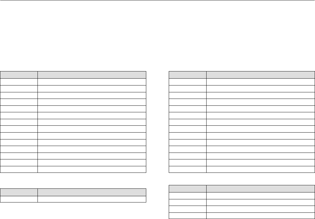
Instruction Manual
D103412X012
Detailed Setup—MAI Function Block
January 2015
163
View Lists
View lists allow the values of a set of parameters to be accessed at the same time. Views 1 and 2 contain operating
parameters and are defined by the Fieldbus Foundation. View 3 contains dynamic parameters and View 4 contains
static parameters with configuration and maintenance information. Views 3 and 4 are defined by the manufacturer.
Table 4‐65. MAI Function Block, View 1
Index Number Parameter
1 ST_REV
5.1 MODE_BLK.TARGET_MODE
5.2 MODE_BLK.ACTUAL_MODE
5.3 MODE_BLK.PERMITTED_MODE
5.4 MODE_BLK.NORMAL_MODE
6 BLOCK_ERR
8 OUT_1
9 OUT_2
10 OUT_3
11 OUT_4
12 OUT_5
13 OUT_6
14 OUT_7
15 OUT_8
Table 4‐66. MAI Function Block, View 2
Index Number Parameter
1 ST_REV
Table 4‐67. MAI Function Block, View 3
Index Number Parameter
1 ST_REV
5.1 MODE_BLK.TARGET_MODE
5.2 MODE_BLK.ACTUAL_MODE
5.3 MODE_BLK.PERMITTED_MODE
5.4 MODE_BLK.NORMAL_MODE
6 BLOCK_ERR
8 OUT_1
9 OUT_2
10 OUT_3
11 OUT_4
12 OUT_5
13 OUT_6
14 OUT_7
15 OUT_8
Table 4‐68. MAI Function Block, View 4
Index Number Parameter
1 ST_REV
3 STRATEGY
4 ALERT_KEY
7 CHANNEL

Instruction Manual
D103412X012
Detailed Setup—MAI Function Block
January 2015
164
Field Communicator Menu Structure
MULTIPLE ANALOG INPUT FUNCTION BLOCK
Quick Config
MAI Channel
Common Config
Alert Key
Block Mode: Target
Block Mode: Actual
Block Mode: Permitted
Block Mode: Normal
Advanced Config
Static Revision
Strategy
I/O Reference
MAI Channel
Online
Block Error
Block Mode: Target
Block Mode: Actual
Block Mode: Permitted
Block Mode: Normal
Output 1: Status
Output 1: Value
Output 2: Status
Output 2: Value
Output 3: Status
Output 3: Value
Output 4: Status
Output 4: Value
Output 5: Status
Output 5: Value
Output 6: Status
Output 6: Value
Output 7: Status
Output 7: Value
Output 8: Status
Output 8: Value
Status
Block Error
All
Characteristics
Static Revision
Tag Description
Strategy
Alert Key
Block Mode: Target
Block Mode: Actual
Block Mode: Permitted
Block Mode: Normal
Block Error
MAI Channel
Output 1: Status
Output 1: Value
Output 2: Status
Output 2: Value
Output 3: Status
Output 3: Value
Output 4: Status
Output 4: Value
Output 5: Status
Output 5: Value
Output 6: Status
Output 6: Value
Output 7: Status
Output 7: Value
Output 8: Status
Output 8: Value
Update Event: Unacknowledged
Update Event: Update State
Update Event: Time Stamp
Update Event: Static Rev
Update Event: Relative Index
Block Alarm: Unacknowledged
Block Alarm: Alarm State
Block Alarm: Time Stamp
Block Alarm: Subcode
Block Alarm: Value
Connectors
Output 1: Status
Output 1: Value
Output 2: Status
Output 2: Value
Output 3: Status
Output 3: Value
Output 4: Status
Output 4: Value
Output 5: Status
Output 5: Value
Output 6: Status
Output 6: Value
Output 7: Status
Output 7: Value
Output 8: Status
Output 8: Value
Other
Tag Description
Update Event: Unacknowledged
Update Event: Update State
Update Event: Time Stamp
Update Event: Static Rev
Update Event: Relative Index
Block Alarm: Unacknowledged
Block Alarm: Alarm State
Block Alarm: Time Stamp
Block Alarm: Subcode
Block Alarm: Value

Instruction Manual
D103412X012
Detailed Setup—DO Function Block
January 2015
165
Discrete Output Function Block
Overview
The Discrete Output (DO) function block (figure 4‐27) processes a discrete set point and outputs it to the specified I/O
channel to produce an output signal. The DVC6200f digital valve controller discrete output block provides both
normal open/closed control and the ability to position the valve in 5% increments for coarse throttling applications.
The digital valve controller measures and uses actual valve position for READBACK_D [16].
Figure 4‐27. Discrete Output (DO) Function Block
DO
CAS_IN_D
BKCAL_OUT_D
OUT_D
BKCAL OUT D = The value and status required by the
BKCAL IN D input of another block for output tracking.
CAS IN D= The remote set point value from another function block.
OUT_D = The block output and status.
READBACK_D
READBACK_D = Actual valve position
The DO block supports mode control and simulation. In operation, the DO function block determines its set point and
sets the output. The transducer block provides a readback signal of actual position from the instrument. Figure 4‐27
illustrates the primary inputs and outputs of the DO function block, figure 4‐28 illustrates the internal components of
the DO function block. Table 4‐72 lists definitions for the function block parameters.
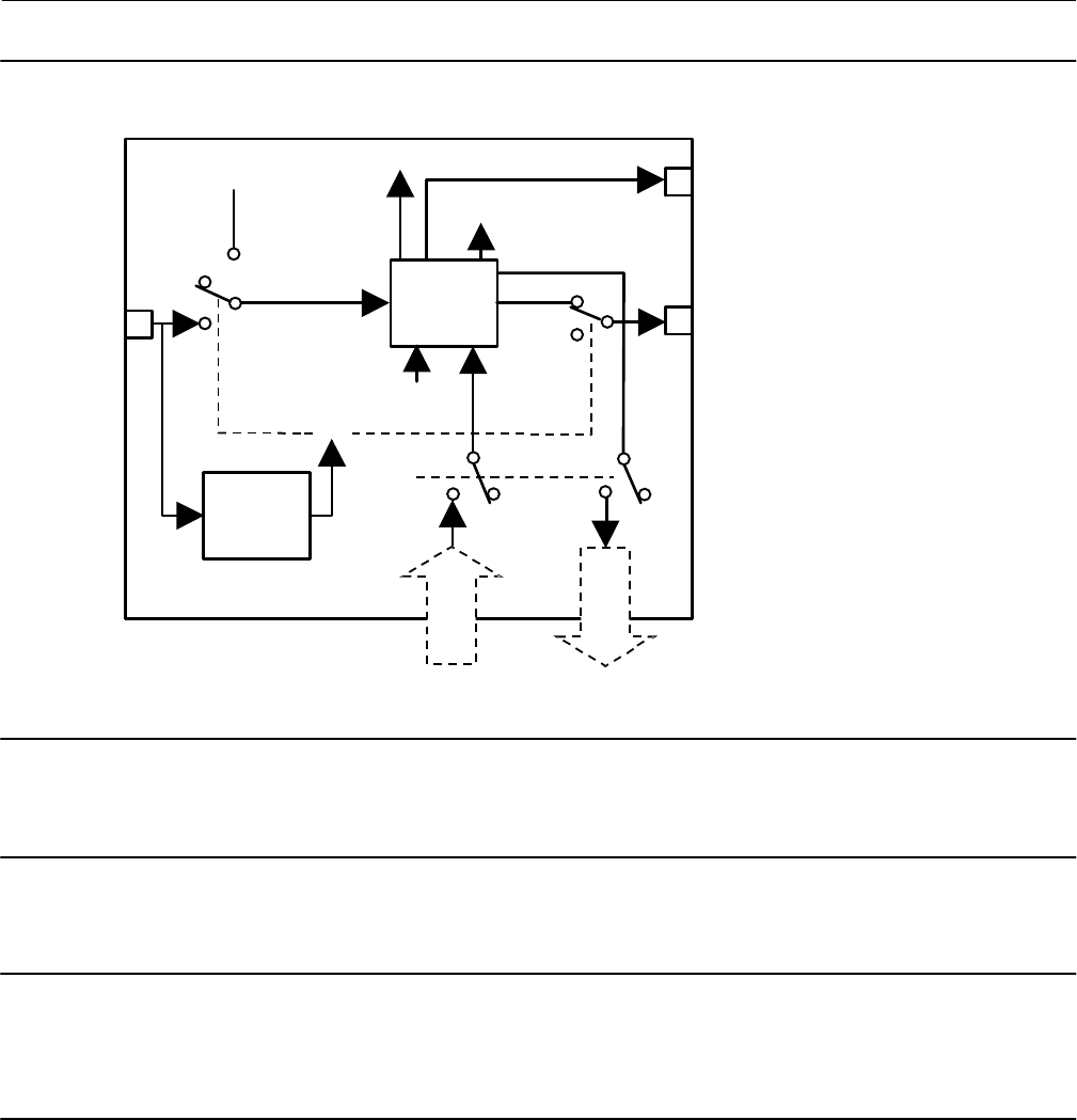
Instruction Manual
D103412X012
Detailed Setup—DO Function Block
January 2015
166
Figure 4‐28. Discrete Output Function Block Schematic
CAS_IN_D
IO_OPTS
RCAS_IN_D
SIMULATE_D
MODE
CHANNEL
TRANSDUCER
BLOCK
SP_D
PV_D
RCAS_OUT_D
OUT_D
BKCAL_OUT_D
READBACK_D
CONVERT AND
STATUS
CALCULATION
SHED MODE
TRANSDUCER
BLOCK FEEDBACK
When setting up the DO block, CHANNEL [18] must be set to 22, and SHED_OPT [23] must be non‐zero.
Note
Actual Block Mode (MODE_BLK.ACTUAL [5.2]) will remain out of service and the block cannot be scheduled if the block has not
been licensed. Contact your Emerson Process Management sales office to upgrade product licensing.
Note
Actual Block Mode (MODE_BLK.ACTUAL [5.2]) will remain in IMAN and the block Readback status will be Bad - Not Connected if
the Output Block Selection is set incorrectly. From the transducer block method Outblock Selection, select the desired output
block, see page 45.
Modes
The DO block supports the following modes:
Manual (Man)—The block output OUT_D [9] value may be entered manually.
Automatic (Auto)—The block algorithm uses the local set point SP_D [8]value to determine OUT_D [9].

Instruction Manual
D103412X012
Detailed Setup—DO Function Block
January 2015
167
Cascade (Cas)—The block uses a set point supplied by another function block.
Note
The transducer block must be in Auto for the mode to go to AUTO, CAS or MAN.
RemoteCascade (RCas)—The block uses a set point supplied by a host computer.
Out of Service (OOS)—The block is not processed and the output is not transferred to I/O. The BLOCK_ERR [6]
attribute shows Out of service.
Mode Handling
Shed Options — RCAS Mode Only
Shed from or climb to a remote mode is determined by the parameter SHED_OPT [23]. A block climbs and sheds
through the same path. For example, if SHED_OPT [23] specifies that a block should shed to Auto, then, if the block
target mode is set to RCas, the block goes through Auto on the way to RCas. You can configure the shed option as
follows:
Shed With Return Options
Remote cascade connection failure shifts actual mode but keeps trying to restore remote cascade (in other words, the
remote cascade target mode stays in effect).
Normal—On failure of a remote cascade connection, the block attempts to attain the highest permitted non‐remote
mode until remote cascade is restored. Cas is the highest permitted non‐remote mode and Auto is is the next
permitted non‐remote mode. If Cas or Auto are not available, the block will shed by default to Man.
Retained Target—The retained target mode is the target mode for the block before changing the target mode to a
remote mode. On failure of a remote cascade connection, the block attempts to attain the retained target mode.
Auto—On failure of a remote cascade connection, the block attempts to attain Auto, if permitted, until remote
cascade is restored.
Man—On failure of a remote cascade connection, the block sheds to Man until a remote cascade connection is
restored.
Shed With No Return Options
For any shed with no return option, the target mode changes as determined by the option. Therefore, there is no
attempt to restore the connection following failure. The behavior on change to the remote cascade target mode is
identical to that for Shed With Return Options.
Normal—On failure of a remote cascade connection, the block sets the target mode to the highest permitted
non‐remote mode. Cas is the highest permitted non‐remote mode and Auto is is the next highest permitted
non‐remote mode. If Cas or Auto are not available, the block will shed by default to Man.
Retained Target—The retained target mode is the target mode for the block before changing the target mode to a
remote mode. On failure of a remote cascade connection, the block sets the target mode to the retained target mode.

Instruction Manual
D103412X012
Detailed Setup—DO Function Block
January 2015
168
Auto—On failure of a remote cascade connection, the block sets the target mode to Auto, if permitted.
Man—On failure of remote cascade connection, the block sets the target mode to Man, if permitted.
The user may configure SHED_OPT [23] so that it calls for a target mode that is not permitted. When doing this, the
mode logic uses the following rules as applied by the remote logic:
Shed logic never results in a non‐permitted target mode.
Shed logic never attempts to attain an actual mode of Auto or Cas if that mode is not permitted.
Block Initialization
The Fieldbus Foundation specification requires that certain parameters have initial values of uninitialized in function
blocks. In addition to setting the Resource block mode to AUTO, the control system or the user must change those
parameters from their uninitialized value to a valid value in order for the function block to move from the Out of
Service mode. For the DO function block, the parameters that must be initialized are:
SHED_OPT [23] (see page 167 for valid values)
CHANNEL [18]
Status Handling
Under normal operating conditions, the status of OUT_D [9] is Good Non‐Cascade, and the status of BKCAL_OUT_D
[21] is Good:Cascade. If the output hardware fails, the status of BKCAL_OUT_D [21] is set to Bad:Device Fail, and the
BLOCK_ERR [6] shows Output Failure. If the hardware used for output feedback fails, the status of READBACK_D [16]
and PV_D [7] is set to Bad:DeviceFail, and the BLOCK_ERR [6] shows Process Variable has Bad Status. If the transducer
block mode is Out of Service, the status of READBACK_D [16] and PV_D [7] is set to Bad:Out of Service.
I/O Selection
To select the I/O associated with the discrete output, configure the value of the CHANNEL [18] parameter. Table 4‐69
lists the valid Channel selections for the DO block.
Table 4‐69. Channel Selections for the Discrete Output Function Block
Selection Transducer Block Parameter Transducer block Index Description
22 SETPOINT_D 32 Discrete Valve Control
0 - - Uninitialized
Setting the Output
To set the output for the DO block, you must first set the mode to define the manner in which the block determines its
set point and output. In Cascade mode, the set point equals the input value at the CAS_IN_D [17] parameter. In
Automatic or Manual mode, the set point must be entered manually by the user. For Automatic, the value must be
written to the SP_D [8] parameter and for Manual, the value must be written to OUT_D [9]. In Remote Cascade mode,
the set point is determined by a host computer that is writing to the RCAS_IN_D [22] parameter. Table 4‐70 lists
discrete states used by the digital valve controller for the set point.

Instruction Manual
D103412X012
Detailed Setup—DO Function Block
January 2015
169
Table 4‐70. Valve Set Point for Discrete State
Discrete State Valve Set Point with IO_OPTS Invert = 0 Valve Set Point with IO_OPTS Invert = 1
0 Closed Open
1 Open Closed
5 5% Closed
10 10% Closed
15 15% Closed
20 20% Closed
25 25% Closed
30 30% Closed
35 35% Closed
40 40% Closed
45 45% Closed
50 50% Closed
55 55% Closed
60 60% Closed
65 65% Closed
70 70% Closed
75 75% Closed
80 80% Closed
85 85% Closed
90 90% Closed
95 95% Closed
100 Open Closed
To further customize the output, configure the following supported I/O options: SP tracks PV in Man,
SP tracks PV in LO, SP Track retained target in Man or LO, Fault State to Value, Use Fault State value on restart, Target
to Man if Fault State activated, and US PV for BKCAL_OUT.
Note
You can configure the supported I/O options in Out of Service mode only.
The SP_PV Track in Man option permits the set point to track the process variable when the block is in Manual mode.
With this option enabled, the set point (SP_D [8]) becomes a copy of the process variable
(PV_D [7]), and a manually‐entered SP_D [8] value is overwritten on the block's next execution cycle. This option can
prevent a state change when transitioning from Manual to Automatic mode. You can disable this option in Manual or
Out of Service mode only.
The Invert option inverts the set point at SP_D [8] before it is stored in OUT_D [9]. With this option enabled, OUT_D
[9] becomes an inverted copy of SP_D [8] where non‐zero values of SP_D [8] are considered a logic 1. With this option
disabled, OUT_D [9] is a direct copy of SP_D [8]. The readback value is processed through the Invert option to become
PV_D [7]. The Use PV for BKCAL_OUT option specifies that BKCAL _OUT equal the value of the process variable (PV_D
[7]) instead of the set point (SP_D [8]). If you do not enable this option, BKCAL_OUT will equal SP_D [8].
Output Block PV Status
The Output Block PV Status is determined by the value of the PlantWeb Alerts Set PV Status parameter in the
transducer block (PWA_SET_STATUS [97]), the Transducer Block mode, and enabled Active PlantWeb alarms. Refer to
table 4‐11.

Instruction Manual
D103412X012
Detailed Setup—DO Function Block
January 2015
170
Block Errors
Table 4‐71 lists conditions reported in the BLOCK_ERR [6] parameter. Conditions in italics are not applicable for the DO
block and are provided only for your reference.
Table 4‐71. BLOCK_ERR Conditions
Condition Number Condition Name and Description
0Other (N/A)
1Block Configuration Error ‐ SHED_OPT or CHANNEL set to 0 (uninitialized)
2Link Configuration Error (N/A)
3Simulate active ‐ Simulation is enabled and the block is using a simulated value in its execution.
4Local Override ‐ Device in fault state. Actual mode LO.
5Device Fault State Set ‐ DO block in fault state after FSTATE_TIME because of Bad status or IFS substatus on CAS_IN_D or Resource
block commanded fault state.
6Device Needs Maintenance Soon ‐ Indicates a Maintenance PlantWeb Alert condition is active if Block Error Reporting is enabled. See
page 62.
7Input failure/process variable has Bad status ‐ PV has bad status and Feature Select in the Resource block has the Out Readback bit set
or the transducer block mode is Out of Service.
8Output failure ‐ PV has bad status or the transducer block mode is Out of Service.
9Memory Failure (N/A)
10 Lost Static Data (N/A)
11 Lost NV Data (N/A)
12 Readback Check Failed (N/A)
13 Device Needs Maintenance Now ‐ Indicates Failed PlantWeb Alert condition is active if Block Error Reporting is enabled. See page 62.
14 Power Up ‐ This condition exists after power up until actual mode is not Out of Service.
15 Out of Service ‐ The block is in Out of Service (OOS) mode.
Action on Fault Detection
Fault State is caused by one of three sources: A status pertaining to CAS, A status pertaining to RCAS, or SET_FSTATE
[29] in the resource block. To implement Fault State, configure the following parameters:
IO_OPTS [14]: Determines the action OUT_D [9] will take upon a fault state. If the IO_OPTS [14] “Fault State to Value”
is not selected, then OUT_D [9] holds its last position when Fault State is set. If “Fault State to Value” is selected,
OUT_D [9] goes to the FSTATE_VAL_D [20] value when Fault State is set.
FSTATE_TIME [19]: The length of time, in seconds, that the DO block will wait to set Fault State. When
Fault State is set, the OUT_D [9] value goes to either the FSTATE_VAL_D [20] value or holds its last position, depending
on I/O_OPTS [14]. When the block has a target mode of CAS, a fault condition will be detected if the CAS_IN_D [17]
has a BAD status or an Initiate Fault State substatus is received from the upstream block.
FSTATE_VAL_D [20]: Determines the OUT_D [9] value if IO_OPTS [14] “Fault State to Value” is selected. The OUT_D
[9] value transitions to FSTATE_VAL_D [20] after FSTATE_TIME [19] elapses and the fault condition has not cleared.
Simulation
To support testing of the control strategy, you can enable the SIMULATE_D [17] parameter. Normally, the valve
position value and status used for READBACK_D [16] in the DO block reflect actual process values to the nearest 5%, as
provided by the transducer block. When the SIMULATE_D [17] parameter is enabled, value and status used for
READBACK_D [16] is supplied by the user manually. To enable simulation in the DO function block, the simulate
jumper must be installed. Refer to page 13 of the Installation section for information on the installation of this jumper.

Instruction Manual
D103412X012
Detailed Setup—DO Function Block
January 2015
171
Note
When simulate is active, the output block no longer writes values to the transducer block. If the Output Blk Timeout period is
exceeded, the transducer block may move the valve to the Zero Power Condition depending on the configuration of the Output
Block Timeout Alert.
The SIMULATE_D [10] parameter has three components:
Simulate Enable_Disable determines whether the function block will use the actual valve position value and status,
or Simulate Value and Simulate Status.
Transducer Value and Status reflect the process values provided by the transducer block.
Simulate Value and Status may be entered by the user when Simulate Enable_Disable is set to Enabled.
To use simulate, first install the simulate jumper in the terminal box, then set Simulate Enable_Disable to Enabled,
then enter the desired values for Simulate Value and Status.
When SIMULATE_D [10] is Enabled, the Simulate Active bit of the BLOCK_ERR [6] parameter is set (refer to the Block
Errors description). When the simulate jumper is installed, the Simulate Jumper bit of the transducer block parameter
SELFTEST_STATUS [78] is set.
DO Function Block Parameter List (table 4‐72)
Read/Write Capability: RO - Read Only, RW - Read Write
Mode: The block mode(s) required to write to the parameter
Double indentation and shaded Index Number indicates sub‐parameter
Table 4‐72. Discrete Output Function Block Parameter Definitions
Label
PARAMETER_NAME
Index
Number
RO /
RW Mode Range Initial Value Description
Static Revision
ST_REV 1 RO N/A 0 to 65535 0
Data Type: Unsigned16
The revision level of the static data associated with
the function block. The revision value will be
incremented each time a static parameter value in
the block is changed.
Tag Description
TAG_DESC 2 RW ALL 7 bit ASCII Spaces
Data Type: Octet String
The user description of the intended application of
the block.
Strategy
STRATEGY 3 RW ALL 0 to 65535 0
Data Type: Unsigned16
The strategy field can be used to identify grouping
of blocks. This data is not checked or processed by
the block.
Alert Key
ALERT_KEY 4 RW ALL 1 to 255 0
Data Type: Unsigned8
The identification number of the plant unit. This
information may be used in the host for sorting
alarms, etc.
-Continued-

Instruction Manual
D103412X012
Detailed Setup—DO Function Block
January 2015
172
Table 4‐72. Discrete Output Function Block Parameter Definitions (Continued)
DescriptionInitial ValueRangeMode
RO /
RW
Index
Number
Label
PARAMETER_NAME
Block Mode
MODE_BLK 5
Data Type: DS‐69
Valid Bits: 7: OOS, 5: LO, 4: MAN, 3: AUTO
2: CAS, 1: RCAS
The actual, target, permitted, and normal modes of
the block.
Target: The requested block mode
Actual: The current mode of the block
Permitted: Allowed modes for Target
Normal: Most common mode for Target
TARGET 5.1 RW ALL
OOS
MAN
AUTO
AUTO‐CAS, AUTO‐RCAS
OOS until
block is
configured,
then last valid
target
ACTUAL 5.2 RO ALL OOS
PERMITTED 5.3 RW ALL OOS+MAN+AUTO+
CAS+RCAS
OOS+MAN+A
UTO+CAS
+RCAS
NORMAL 5.4 RW ALL AUTO+CAS
Block Error
BLOCK_ERR 6 RO N/A
1: Block Configuration
Error
3: Simulate Active
4: Local Override
5: Device Fault State Set
7: Input Failure / Bad PV
Status
8: Output Failure
14: Power‐up
15: Out‐of‐Service
Dynamic
Data Type: Bit String
0=Inactive
1=Active
This parameter reflects the error status associated
with the hardware or software components
associated with a block. It is a bit string, so that
multiple errors may be shown.
Process Value Discrete
PV_D 7 RO N/A PV_D Status set equal
to Readback_D Status Dynamic
Data Type: DS‐66
The discrete process variable calculated from
READBACK_D.
Setpoint Discrete
SP_D 8
OOS
MAN
AUTO
PV_STATE Data Type: DS‐66
The discrete target block output value (set point).
Output Discrete
OUT_D 9 MAN OUT_STATE
Data Type: DS‐66
Position target of valve. 0=closed, 1=open, 2-100
position the value in 5% steps.
Simulate Discrete
SIMULATE_D 10
Data Type: DS‐83
Allows the transducer discrete input or output to
the block to be manually supplied when simulate is
enabled. When simulation is disabled, the simulate
value and status track the actual value and status.
SIMULATE_STATUS 10.1 ALL 0
SIMULATE_VALUE 10.2 ALL 0
TRANSDUCER_STATUS 10.3 RO 0
TRANSDUCER_VALUE 10.4 RO 0
ENABLE/DISABLE 10.5 ALL
0=Not initialized
1=Simulation Disabled
2=Simulation Active
1
Process Value State
PV_STATE 11 ALL 0
Data Type: Uint16
Index to the text describing the states of a discrete
output.
Transducer State
XD_STATE 12 ALL 0
Data Type: Uint16
Index to the text describing the states of a discrete
for the value obtained from the transducer.
Grant Deny
GRANT_DENY 13 Data Type: DS‐70
Options for controlling access of host computers
and local control panels to operating, tuning, and
alarm parameters of the block.
GRANT:0=N/A, 1=granted
DENY: 0=N/A, 1=denied
GRANT 13.1 N/A 0: Program
1: Tune
2: Alarm
3: Local
All bits: 0
DENY 13.2 N/A All bits: 0
-Continued-

Instruction Manual
D103412X012
Detailed Setup—DO Function Block
January 2015
173
Table 4‐72. Discrete Output Function Block Parameter Definitions (Continued)
DescriptionInitial ValueRangeMode
RO /
RW
Index
Number
Label
PARAMETER_NAME
I/O Options
IO_OPTS 14 OOS
Valid Bits
0: Invert
1: SP tracks PV in Man
3: SP tracks PV in LO
4: SP Track retained
target in Man or LO
6: Fault State to value
0: freeze
1: go to Fault State
value
7: Use Fault State value
on restart
8: Target to Man if Fault
State activated
9: Use PV for
BKCAL_OUT
0: SP
1: PV
All bits: 0
Data Type: Bit String
0=Disable
1=Enable
Allows you to select the type of tracking and the
output value when a fault condition occurs.
Supported I/O options for the DO function block are
SP Tracks PV in Man, SP Tracks PV in LO, SP Tracks
Retained Target in Man or LO, Fault State to Value,
Use Fault state on Restart, Target to Man if Fault
State Activated, and Use PV for BKCAL_OUT.
Status Options
STATUS_OPTS 15 OOS 4: Propagate Failure
Backward All bits: 0
Data Type: Bit String
0=Disable
1=Enable
Options the user may select for the block processing
of status.
Readback Discrete
READBACK_D 16 RO N/A Dynamic
Data Type: DS‐66
0=closed, 1=open, 5, 10, 15, 30...etc. are position in
5% increments.
Cascade Input Discrete
CAS_IN_D 17 ALL Status
BAD:
NC:
const Data Type: DS‐66
The remote set point value from another block.
Value 0
DO Channel
CHANNEL 18 OOS 0=undefined
22=Setpoint (D)
22=
Setpoint (D)
Data Type: Unsigned16
Defines which transducer parameter receives the
DO output. Select Setpoint (D) to control valve
position.
Fault State Time
FSTATE_TIME 19 ALL Positive 0
Data Type: Float
Time from detection of a fault in the remote set
point to the Fault State output action.
Fault State Value Discrete
FSTATE_VAL_D 20 ALL 0
Date Type: Unsigned8
Preset discrete SP_D value to use if I/O_OPTS Fault
State to Value is set.
Back Calculation Output Discrete
BKCAL_OUT_D 21 RO N/A Dynamic
Data Type: DS‐66
The value and status required by the BKCAL_IN_D
input of another block for output tracking
Remote Cascade Input Discrete
RCAS_IN_D 22 ALL Status
BAD:
NoCom:
NoVal:
const
Date Type: DS‐66
Target set point and status provided by a
supervisory host to a discrete control or output
block.
Value 0
-Continued-

Instruction Manual
D103412X012
Detailed Setup—DO Function Block
January 2015
174
Table 4‐72. Discrete Output Function Block Parameter Definitions (Continued)
DescriptionInitial ValueRangeMode
RO /
RW
Index
Number
Label
PARAMETER_NAME
Shed Options
SHED_OPT 23 ALL
0=Uninitialized
1=Normal Shed, Normal
Return
2=Normal Shed, No
Return
3=Shed to Auto, normal
return
4=Shed to Auto, no
return. Target mode
changes to Auto on
detection of a shed
condition
5=Shed to Manual,
normal return
6=Shed to Manual, No
return. Target mode
changes to MAN on
detection of a shed
condition.
7=Shed to retained
target, normal return
8=Shed to retained
target, no return.
(Change target to
retained target)
0
Data Type: Unsigned8
Defines action to be taken on remote control device
timeout.
Normal Return - actual mode changes to the next
lowest priority non‐remote mode permitted but
returns to the target remote mode when the
remote computer completes the initialization
handshake.
No Return - Target mode changes to the next lowest
priority non‐remote mode permitted. The target
remote mode is lost, so no return occurs.
Remote Cascade Output Discrete
RCAS_OUT_D 24 RO N/A Dynamic
Data Type: DS‐66
Block set point and status after ramping, provided
to a supervisory host for back calculation and to
allow action to be taken under limiting conditions or
mode change.
Update Event
UPDATE_EVT 25
Data Type: DS‐73
This alert is generated by any change to the static
data.
UNACKNOWLEDGED 25.1 RW N/A
0=Undefined
1=Acknowledged
2=Unacknowledged
0=Undefined
UPDATE_STATE 25.2 RO N/A
0=Undefined
1=Update reported
2=Update not reported
0=Undefined
TIME_STAMP 25.3 RO N/A 0
STATIC_REVISION 25.4 RO N/A 0
RELATIVE_INDEX 25.5 RO N/A 0
Block Alarm
BLOCK_ALM 26
Data Type: DS‐72
The block alarm is used for all configuration,
hardware, connection failure, or system problems in
the block. The cause of the alert is entered in the
subcode field. The first alert to become active will
set the active status in the status parameter. As
soon as the Unreported status is cleared by the alert
reporting procedure, and other block alert may be
reported without clearing the Active status, if the
subcode has changed.
UNACKNOWLEDGED 26.1 RW N/A
0=Undefined
1=Acknowledged
2=Unacknowledged
0
ALARM_STATE 26.2 RO N/A
0=Undefined
1=Clear reported
2=Clear not reported
3=Active reported
4=Active not reported
0
TIME_STAMP 26.3 RO N/A 0
SUBCODE 26.4 RO N/A 0
VALUE 26.5 RO N/A 0
Extended Blocks
Setpoint Rate Up
SP_RATE_UP 27 > = 0 0
Data Type: Float
The ramp rate for SP up in AUTO, CAS, and RCAS
modes. Measured in PV units/sec.
Setpoint Rate Down
SP_RATE_DN 28 > = 0 0
Data Type: Float
The ramp rate for SP down in AUTO, CAS, and RCAS
modes. Measured in PV units/sec.

Instruction Manual
D103412X012
Detailed Setup—DO Function Block
January 2015
175
View Lists
View lists allow the values of a set of parameters to be accessed at the same time. Views 1 and 2 contain operating
parameters and are defined by the Fieldbus Foundation. View 3 contains dynamic parameters and View 4 contains
static parameters with configuration and maintenance information. Views 3 and 4 are defined by the manufacturer.
Table 4‐73. DO Function Block, View 1
Index Number Parameter
1 ST_REV
5.1 MODE_BLK.TARGET_MODE
5.2 MODE_BLK.ACTUAL_MODE
5.3 MODE_BLK.PERMITTED_MODE
5.4 MODE_BLK.NORMAL_MODE
6 BLOCK_ERR
7 PV_D
8 SP_D
9 OUT_D
16 READBACK_D
17 CAS_IN_D
Table 4‐74. DO Function Block, View 2
Index Number Parameter
1 ST_REV
11 PV_STATE
12 XD_STATE
13.1 GRANT_DENY.GRANT
13.2 GRANT_DENY.DENY
Table 4‐75. DO Function Block, View 3
Index Number Parameter
1 ST_REV
5.1 MODE_BLK.TARGET_MODE
5.2 MODE_BLK.ACTUAL_MODE
5.3 MODE_BLK.PERMITTED_MODE
5.4 MODE_BLK.NORMAL_MODE
6 BLOCK_ERR
7 PV_D
8 SP_D
9 OUT_D
16 READBACK_D
17 CAS_IN
21 BKCAL_OUT_D
22 RCAS_IN_D
24 RCAS_OUT_D
Table 4‐76. DO Function Block, View 4
Index Number Parameter
1 ST_REV
3 STRATEGY
4 ALERT_KEY
14 IO_OPTS
15 STATUS_OPTS
18 CHANNEL
19 FSTATE_TIME
20 FSTATE_VAL_D
24 SHED_OPT
27 SP_RATE_UP
28 SP_RATE_DN

Instruction Manual
D103412X012
Detailed Setup—DO Function Block
January 2015
176
DISCRETE OUTPUT FUNCTION BLOCK
Quick Config
Alert Key
Process Value Discrete: Status
Process Value Discrete: Value
Setpoint Discrete: Status
Setpoint Discrete: Value
Common Config
Alert Key
I/O Options
Block Mode: Target
Block Mode: Actual
Block Mode: Permitted
Block Mode: Normal
Setpoint Discrete: Status
Setpoint Discrete: Value
Advanced Config
Fault State Time
Fault State Value Discrete
Process Value State
Shed Options
Simulate Discrete: Simulate Status
Simulate Discrete: Simulate Value
Simulate Discrete: Transducer Status
Simulate Discrete: Transducer Value
Simulate Discrete: Simulate En/Disable
Static Revision
Status Options
Strategy
Transducer State
I/O Reference
DO Channel
Online
Back Calculation Output Discrete: Status
Back Calculation Output Discrete: Value
Block Error
Cascade Input Discrete: Status
Cascade Input Discrete: Value
Block Mode: Target
Block Mode: Actual
Block Mode: Permitted
Block Mode: Normal
Output Discrete: Status
Output Discrete: Value
Process Value Discrete: Status
Process Value Discrete: Value
Remote Cascade Input Discrete: Status
Remote Cascade Input Discrete: Value
Remote Cascade Output Discrete: Status
Remote Cascade Output Discrete: Value
Readback Discrete: Status
Readback Discrete: Value
Setpoint Discrete: Status
Setpoint Discrete: Value
Status
Block Error
All
Characteristics
Static Revision
Tag Description
Strategy
Alert Key
Block Mode: Target
Block Mode: Actual
Block Mode: Permitted
Block Mode: Normal
Block Error
Process Value Discrete: Status
Process Value Discrete: Value
Setpoint Discrete: Status
Setpoint Discrete: Value
Output Discrete: Status
Output Discrete: Value
Simulate Discrete: Simulate Status
Simulate Discrete: Simulate Value
Simulate Discrete: Transducer Status
Simulate Discrete: Transducer Value
Simulate Discrete: Simulate En/Disable
Process Value State
Transducer State
Grant Deny: Grant
Grant Deny: Deny
I/O Options
Status Options
Readback Discrete: Status
Readback Discrete: Value
Cascade Input Discrete: Status
Cascade Input Discrete: Value
DO Channel
Fault State Time
Fault State Value
Back Calculation Output Discrete: Status
Back Calculation Output Discrete: Value
Remote Cascade Input Discrete: Status
Remote Cascade Input Discrete: Value
Shed Options
Remote Cascade Output Discrete: Status
Remote Cascade Output Discrete: Value
Update Event: Unacknowledged
Update Event: Update State
Update Event: Time Stamp
Update Event: Static Rev
Update Event: Relative Index
Block Alarm: Unacknowledged
Block Alarm: Alarm State
Block Alarm: Time Stamp
Block Alarm: Subcode
Block Alarm: Value
Setpoint Rate Up
Setpoint Rate Down
Connectors
Back Calculation Output Discrete: Status
Back Calculation Output Discrete: Value
Cascade Input Discrete: Status
Cascade Input Discrete: Value
Output Discrete: Status
Output Discrete: Value
Other
Tag Description
Grant Deny: Grant
Grant Deny: Deny
Update Event: Unacknowledged
Update Event: Update State
Update Event: Time Stamp
Update Event: Static Rev
Update Event: Relative Index
Block Alarm: Unacknowledged
Block Alarm: Alarm State
Block Alarm: Time Stamp
Block Alarm: Subcode
Block Alarm: Value
Setpoint Rate Up
Setpoint Rate Down
Field Communicator Menu Structure
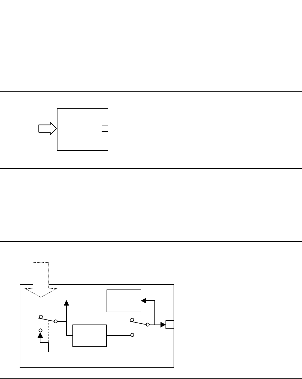
Instruction Manual
D103412X012
Detailed Setup—DI Function Block
January 2015
177
Discrete Input Function Block
Overview
The Discrete Input (DI) function block (figure 4‐29) processes a single discrete input from a field device and makes it
available to other function blocks. You can configure inversion and alarm detection on the input value. In the
DVC6200f digital valve controller, the discrete input function block can provide limit switch functionality and valve
position proximity detection. The DI function block supports mode control, signal status propagation, and simulation.
Figure 4‐29. Discrete Input (DI) Function Block
DI
OUT_D = The block output and status
OUT_D
TRANSDUCER
BLOCK
Normally, the block is used in Automatic mode so that the process variable (PV_D [7]) is copied to the output (OUT_D
[8]). You can change the mode to Manual to disconnect the field signal and substitute a manually‐entered value for
the output. In this case, PV_D [7] continues to show the value that will become the OUT_D [8] when the mode is
changed to Automatic.
To support testing, you can enable simulation, which allows the measurement value to be supplied manually through
the SIMULATE_D [9] parameter. Figure 4‐30 illustrates the internal components of the DI function block, and table
4‐81 lists the definitions of the block parameters.
Figure 4‐30. Discrete Input Function Block Schematic
Invert Option
Alarm Detection
FIELD_VAL_D
MODESIMULATE
PV_D
OUT_D
Discrete Signal

Instruction Manual
D103412X012
Detailed Setup—DI Function Block
January 2015
178
Modes
The Discrete Input function block supports the following modes:
Manual (Man)—The block output (OUT_D [8]) is disconnected from the field and set manually.
Automatic (Auto)—The block algorithm determines output.
Out of Service (OOS)—The block is not processed. The OUT_D [8] status is set to Bad: Out of Service. The
BLOCK_ERR [6] parameter shows Out of Service.
Block Initialization
The Fieldbus Foundation specification requires that certain parameters in the function blocks have initial values of
uninitialized. In addition to setting the Resource block mode to AUTO, the control system or the user must change
those parameters from their uninitialized value to a valid value in order for the function block to move from the Out of
Service mode. For the DI function block, the CHANNEL [15] parameter must be initialized.
Status Handling
Under normal conditions, a Good: Non‐Cascade status is passed through to OUT_D [8]. The block also supports the
Status Action On Failure and BLOCK_ERR [6] indications.
When SIMULATE_D [9] is enabled, FIELD_VAL_D [7], PV_D [7], and OUT_D [8] change to the simulated status. When
the block is set to Manual mode, OUT_D [7] is set to Good: Non-cascade, Constant status.
I/O Selection
To select the I/O associated with the discrete measurement, configure the value of the CHANNEL [15] parameter.
In the digital valve controller, the four classes of channels are
Valve travel
Open/Closed limit switch
Variable limit switch based on transducer block travel alarm settings.
Proximity position detection based on transducer block travel alarm settings.
The CHANNEL [15] parameter for each of the four DI blocks available in the digital valve controller may be set
independently to achieve the desired position detection. The DI block CHANNEL [15] definitions are listed in table
4‐77. Refer to the following descriptions for details of the operation of these channels.
Valve Travel
Channel 23 provides valve travel.
0 = Closed, 1 = 100% open, 5 = 5% open, 10 = 10% open, 15 = 15% open, etc.

Instruction Manual
D103412X012
Detailed Setup—DI Function Block
January 2015
179
Table 4‐77. Channel Selection for the Discrete Input Function Block
Selection Transducer Block Parameter(1) Transducer Block Index Number Bit Number(2)
23 TRAVEL_D 33 N/A
24 INST_ALERTS_ACTIVE:PROX_ACTIVE 74.5 0: Travel Open
25 INST_ALERTS_ACTIVE:PROX_ACTIVE 74.5 1: Travel Closed
26 INST_ALERTS_ACTIVE:TRAVEL_ACTIVE 74.4 2: Travel Limit Lo Lo
27 INST_ALERTS_ACTIVE:TRAVEL_ACTIVE 74.4 4: Travel Limit Lo
28 INST_ALERTS_ACTIVE:TRAVEL_ACTIVE 74.4 3: Travel Limit Hi
29 INST_ALERTS_ACTIVE:TRAVEL_ACTIVE 74.4 1: Travel Limit Hi Hi
30 INST_ALERTS_ACTIVE:PROX_ACTIVE 74.5 5: Proximity Lo Lo
31 INST_ALERTS_ACTIVE:PROX_ACTIVE 74.5 4: Proximity Lo
32 INST_ALERTS_ACTIVE:PROX_ACTIVE 74.5 3: Proximity Hi
33 INST_ALERTS_ACTIVE:PROX_ACTIVE 74.5 2: Proximity Hi Hi
1. Refer to table 4‐14 for parameter descriptions.
2. See pages 50 and 52, Travel ALerts and Prox Alerts, for information on accessing these alerts. Refer to Appendix F for information on accessing these alerts through DeltaV.
Open/Closed Limit Switch
Channels 24 and 25 provide valve open and closed limit switch functionality for the DI block. These channels will
detect if the valve position is more than the Travel Open Alert Point for open detection or less than the Travel Closed
Alert Point for closed detection. These channels provide an adjustable deadband to clear the detected position.
0= Not Active, 1= Active
Variable Limit Switch
Channels 26 through 29 provide variable limit switch functionality for the DI block. Trip points for this limit switch
functionality are based on the Travel Alert settings in the transducer Block. The DI function block provides the same
type of position detection as the travel alerts in the transducer block. Table 4‐78 lists the transducer block parameters
used with DI block channels 26 through 29. Refer to Travel and Prox, on page 50 for more information on the
transducer block travel alerts.
0= Not Active, 1= Active
Table 4‐78. Transducer Block Parameters Used with Discrete Input Function Block Channels 26 through 29
(Variable Limit Switch)
Transducer Block Parameter Parameter Function
Travel Lo Lo Alert Point Lo Lo Limit Switch Trip Point
Travel Lo Lo Alert Deadband Lo Lo Limit Switch Deadband
Travel Lo Alert Point Lo Limit Switch Trip Point
Travel Lo Alert Deadband Lo Limit Switch Deadband
Travel Hi Alert Point Hi Limit Switch Trip Point
Travel Hi Alert Deadband Hi Limit Switch Deadband
Travel Hi Hi Alert Point Hi Hi Limit Switch Trip Point
Travel Hi Hi Alert Deadband Hi Hi Limit Switch Deadband
Valve Position Proximity Detection
Channels 30 through 33 provide valve position proximity detection for the DI block. The transducer block Travel Alert
Point and Travel Alert Deadband parameters are also used with the valve position proximity, but they provide a
different function. The Travel Alert Point for the selected channel determines the center point for the position to be
detected. The Travel Alert Deadband for the selected channel sets the upper and lower trigger points, or the width of
the proximity detection band. A 1% deadzone exists above and below this band that the travel must exceed to clear
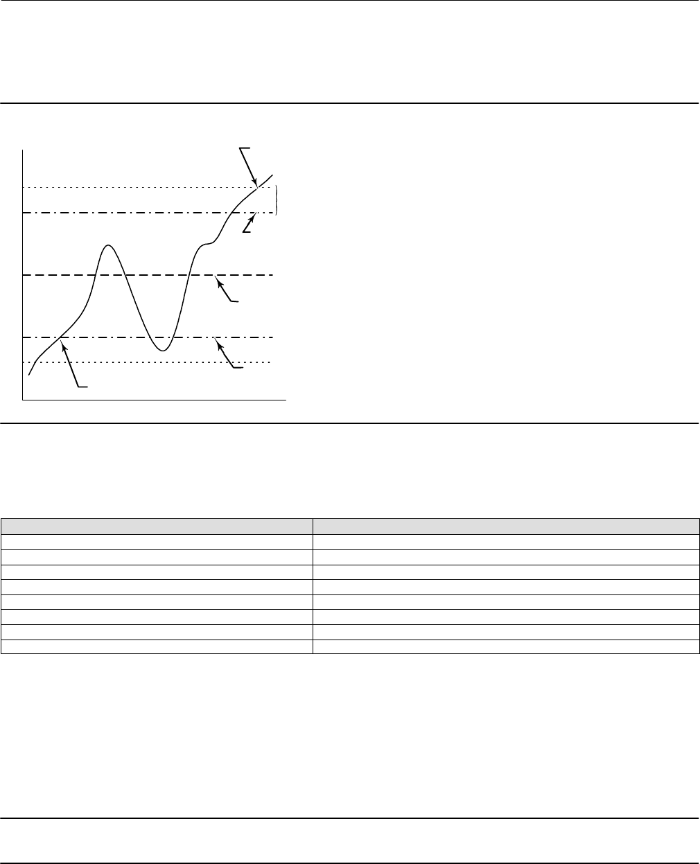
Instruction Manual
D103412X012
Detailed Setup—DI Function Block
January 2015
180
the detected position. Figure 4‐31 illustrates the operation of the proximity detection function. Travel Alert Point
refers to Travel Lo Alert Point, Travel Hi Alert Point, Travel Lo Lo Alert Point, and Travel Hi Hi Alert Point in table 4‐79.
Travel Alert Deadband refers to Travel Lo Alert Deadband, Travel Hi Alert Deadband, Travel Lo Lo Alert Deadband, and
Travel Hi Hi Alert Deadband in table 4‐79.
Figure 4‐31. Discrete Input Proximity Detection Function
DISCRETE INPUT SET
DISCRETE INPUT
CLEARED
TRIGGER POINT FOR DOWNWARD VALVE
TRAVEL DETERMINED BY TRAVEL ALERT
DEADBAND
TRIGGER POINT FOR UPWARD VALVE TRAVEL
DETERMINED BY TRAVEL ALERT DEADBAND
DEADZONE, 1% OF TRAVEL
Valve Position
CENTER POINT OF PROXIMITY DETECTION
DETERMINED BY TRAVEL ALERT POINT
0= Not Active, 1= Active
Table 4‐79 lists the transducer block parameters used for proximity detection with DI block channels 30 through 33.
Table 4‐79. Transducer Block Parameters Used with Discrete Input Function Block Channels 30 through 33
Transducer Block Parameter Parameter Function
Travel Lo Lo Alert Point Lo Lo Proximity Detection Center Point
Travel Lo Lo Alert Deadband Lo Lo Proximity Detection Width
Travel Lo Alert Point Lo Proximity Detection Center Point
Travel Lo Alert Deadband Lo Proximity Detection Width
Travel Hi Alert Point Hi Proximity Detection Center Point
Travel Hi Alert Deadband Hi Proximity Detection Width
Travel Hi Hi Alert Point Hi Hi Proximity Detection Center Point
Travel Hi Hi Alert Deadband Hi Hi Proximity Detection Width
Field Value Processing
The Invert bit of the IO_OPTS [13] parameter may be used to logically invert the value of FIELD_VAL_D [17] before it is
stored as PV_D [7]. PV_FTIME [16] may
be used to set the length of time that FIELD_VAL_D [17] must be in a new state before that new state is reflected in
PV_D. The PV_D [7] value goes to the mode switch where it becomes OUT_D [8] when the actual mode is AUTO.
OUT_D [8] is also tested for an alarm state.
Note
Invert is the only I/O option that the DI block supports. You can set the I/O option only when the block mode is Out of Service.

Instruction Manual
D103412X012
Detailed Setup—DI Function Block
January 2015
181
Alarm Detection
To select the state that initiates an input alarm, and to set discrete alarm substatus in the output, configure the
DISC_LIM [23] parameter. You can enter any value between 0 and 255. A value of 255 disables the alarm. When
OUT_D [8] matches the DISC_LIM [23] state, the discrete value of an alarm is set.
Block Errors
Table 4‐80 lists conditions reported in the BLOCK_ERR [6] parameter. Conditions in italics are not applicable for the DI
block and are provided only for your reference.
Table 4‐80. BLOCK_ERR Conditions
Condition Number Condition Name and Description
0Other (N/A)
1Block Configuration Error—CHANNEL set to 0 through 10 (uninitialized)
2Link Configuration Error (N/A)
3Simulate Active—Simulate is enabled. Output does not reflect process conditions
4Local Override (N/A)
5Device Fault State Set (N/A)
6Device Needs Maintenance Soon (N/A)
7Input failure/process variable has Bad status—The hardware is bad or the transducer block mode is Out of Service
8Output Failure (N/A)
9Memory Failure (N/A)
10 Lost Static Data (N/A)
11 Lost NV Data (N/A)
12 Readback Check Failed (N/A)
13 Device Needs Maintenance Now (N/A)
14 Power Up—Set after power‐up until actual mode is not Out of Service
15 Out of Service—The actual mode is Out of Service (OOS). The block is not being processed.
Action on Failure
In case of hardware failure, FIELD_VAL_D [17], PV_D [7], and OUT_D [8] change to a Bad status and the BLOCK_ ERR
[6] parameter shows Process Variable has Bad Status. If the transducer block mode is Out of Service, the status of
FIELD_VAL_D [17], PV_D [7], and OUT_D [8] is set to Bad:Out of Service.
Simulation
To support testing of the control strategy, you can enable the SIMULATE_D [9] parameter. Normally the measurement
value and status used for FIELD_VAL_D [17] in the DI block reflect actual process values as provided by the transducer
block. When the SIMULATE_D [9] parameter is enabled, value and status used for FIELD_VAL_D [17] is supplied by the
user manually. To enable simulation in the DI function block, the simulate jumper must be installed. For information
on the installation of this jumper, see the Installation section.
The SIMULATE_D [9] parameter has three components:
Simulate_D enable/disable determines whether the function block will use the actual process value and status, or
Simulate Value and Simulate Status.
Transducer Value and Status reflect the process values provided by the transducer block.
Simulate Value and Status may be entered by the user when enable/disable is set to enabled.
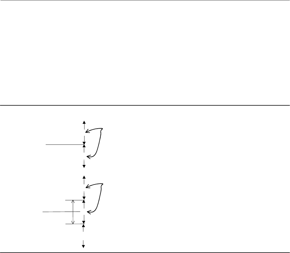
Instruction Manual
D103412X012
Detailed Setup—DI Function Block
January 2015
182
To use simulate, first install the simulate jumper in the terminal box, then set Simulate_D enable/disable to enabled,
then enter the desired values for Simulate Value and Status.
When SIMULATE_D [9] is enabled, the Simulate Active bit of the BLOCK_ERR [6] parameter is set (refer to the Block
Errors description). When the simulate jumper is installed, the Simulate Jumper bit of the transducer block parameter
SELFTEST_STATUS [78] is set.
Application Information
Figure 4‐32 compares the operation of a standard discrete input to a proximity discrete input. With the standard
discrete input, the discrete input changes state when the valve position passes a configurable trip point. This can be
used to indicate if the valve position is above or below the trip point.
Figure 4‐32. Proximity Discrete Input Compared to a Standard Discrete Input
Configurable
Band
DISCRETE
INPUT VALUE
0
0
1
0
1
STANDARD DISCRETE INPUT
PROXIMITY DISCRETE INPUT
DISCRETE
INPUT VALUE
With the proximity discrete input a configurable band can be established about a central point. Whenever the valve
position enters this configurable band, the discrete input changes state. A proximity discrete input is useful for
applications which require knowing the location of the valve when the valve is not near 0% or 100%.
DI Function Block Parameter List (table 4‐81)
Read/Write Capability: RO - Read Only, RW - Read Write
Mode: The block mode(s) required to write to the parameter
Double indentation and shaded Index Number indicates sub‐parameter

Instruction Manual
D103412X012
Detailed Setup—DI Function Block
January 2015
183
Table 4‐81. Discrete Input Function Block Parameter Definitions
Label
PARAMETER_NAME
Index
Number
RO /
RW
Block
Mode Range Initial Value Description
Static Revision
ST_REV 1 RO N/A 0 to 65535 0
Data Type: Unsigned16
The revision level of the static data associated
with the function block. The revision value will
be incremented each time a static parameter
value in the block is changed.
Tag Description
TAG_DESC 2 RW ALL 7 bit ASCII Spaces
Data Type: Octet String
The user description of the intended
application of the block.
Strategy
STRATEGY 3 RW ALL 0 to 65535 0
Data Type: Unsigned16
The strategy field can be used to identify
grouping of blocks. This data is not checked or
processed by the block.
Alert Key
ALERT_KEY 4 RW ALL 1 to 255 0
Data Type: Unsigned8
The identification number of the plant unit.
This information may be used in the host for
sorting alarms, etc.
Block Mode
MODE_BLK 5
Data Type: DS‐69
Valid Bits: 7:OOS, 4:MAN, 3:AUTO
The actual, target, permitted, and normal
modes of the block.
Target: The requested block mode
Actual: The current mode of the block
Permitted: Allowed modes for Target
Normal: Most common mode for Target
TARGET 5.1 RW ALL
OOS
MAN
AUTO
OOS until
block is
configured,
then last valid
target
ACTUAL 5.2 RO ALL OOS
PERMITTED 5.3 RW ALL OOS+MAN+AUTO OOS+MAN+A
UTO
NORMAL 5.4 RO ALL AUTO
Block Error
BLOCK_ERR 6 RO N/A
Defined Bits
1: Block Configuration
Error
3: Simulate Active
7: Input Failure / Bad PV
Status
14: Power‐up
15: Out‐of‐Service
Dynamic
Data Type: Bit String
0=Inactive
1=Active
This parameter reflects the error status
associated with the hardware or software
components associated with a block. Multiple
errors may be shown, see table 4‐80.
Process Value Discrete
PV_D 7 RO N/A PV_D Status set equal to
Field_Val_D Status Dynamic
Data Type: DS‐66
The process variable used in block execution.
Value is converted from Readback to show the
actuator position in the same units as the set
point value.
Output Discrete
OUT_D 8OOS
MAN OUT_STATE
Data Type: DS‐66
The primary discrete value calculated as a
result of executing the function.
Simulate Discrete
SIMULATE_D 9
Data Type: DS‐83
Allows the transducer discrete input or output
to the block to be manually supplied when
simulate is enabled. When simulation is
disabled, the simulate value and status track
the actual value and status.
SIMULATE_STATUS 9.1 ALL 0
SIMULATE_VALUE 9.2 ALL 0
TRANSDUCER_STATUS 9.3 RO ALL 0
TRANSDUCER_VALUE 9.4 RO ALL 0
ENABLE/DISABLE 9.5
0=Not initialized
1=Simulation Disabled
2=Simulation Active
1=Simulation
Disabled
Transducer State
XD_STATE 10 ALL 0
Data Type: Uint16
Index to the text describing the states of a
discrete for the value obtained from the
transducer.
Output State
OUT_STATE 11 ALL 0
Data Type: Unsigned16
Index to the text describing the states of a
discrete output.
-Continued-

Instruction Manual
D103412X012
Detailed Setup—DI Function Block
January 2015
184
Table 4‐81. Discrete Input Function Block Parameter Definitions (Continued)
DescriptionInitial ValueRange
Block
Mode
RO /
RW
Index
Number
Label
PARAMETER_NAME
Grant Deny
GRANT_DENY 12 Data Type: DS‐70
Options for controlling access of host
computers and local control panels to
operating, tuning, and alarm parameters of
the block.
GRANT: 0=NA, 1=granted
DENY: 0=NA, 1=denied
GRANT 12.1 ALL 0: Program
1: Tune
2: Alarm
3: Local
All bits:0
DENY 12.2 ALL All bits: 0
I/O Options
IO_OPTS 13 OOS 0: Invert All bits:0
Data Type: Bit String
0=Disable
1=Enable
Allows you to select how the I/O signals are
processed.
Status Options
STATUS_OPTS 14 OOS
3=Propagate Failure
Forward
8=Uncertain in MAN mode
All bits:0
Data Type: Bit String
0=Disable
1=Enable
Options the user may select for the block
processing of status.
DI Channel
CHANNEL 15 OOS
0=undefined
23=Valve Position or
Pressure (Discrete)
24= PV > 97%
25= PV < 3%
26=PV Below LO LO limit
27=PV Below LO limit
28=PV Above HI limit
29=PV Above HI HI limit
30=PV Within Proximity of
LO LO
31=PV Within Proximity of
LO
32=PV within Proximity of
HI
33=PV within Proximity of
HI HI
0=Undefined
Data Type: Unsigned16
Defines the functionality of the discrete input.
See I/O Selection for details. Refer to table
4‐77.
Process Value Filter Time
PV_FTIME 16 ALL Positive 0
Data Type: Float
Time that FIELD_VAL_D must be in a new
state, before the change is reflected to PV_D
and OUT_D.
Field Value Discrete
FIELD_VAL_D 17 RO 0
Data Type: DS‐66
Raw value of the field device discrete input,
with a status reflecting the transducer
condition.
Update Event
UPDATE_EVT 18
Data Type: DS‐73
This alert is generated by any change to the
static data.
UNACKNOWLEDGED 18.1 RW N/A
0=Undefined
1=Acknowledged
2=Unacknowledged
0=Undefined
UPDATE_STATE 18.2 RO N/A
0=Undefined
1=Update Reported
2=Updated not reported
0=Undefined
TIME_STAMP 18.3 RO N/A 0
STATIC_REVISION 18.4 RO N/A 0
RELATIVE_INDEX 18.5 RO N/A 0
-Continued-

Instruction Manual
D103412X012
Detailed Setup—DI Function Block
January 2015
185
Table 4‐81. Discrete Input Function Block Parameter Definitions (Continued)
DescriptionInitial ValueRange
Block
Mode
RO /
RW
Index
Number
Label
PARAMETER_NAME
Block Alarm
BLOCK_ALM 19 Dynamic
Data Type: DS‐72
The block alarm is used for all configuration,
hardware, connection failure, or system
problems in the block. The cause of the alert is
entered in the subcode field. The first alert to
become active will set the active status in the
status parameter. As soon as the unreported
status is cleared by the alert reporting
procedure, and other block alert may be
reported without clearing the active status, if
the subcode has changed.
UNACKNOWLEDGED 19.1 RW N/A
0=Undefined
1=Acknowledged
2=Unacknowledged
ALARM_STATE 19.2 RO N/A
0=Undefined
1=Clear reported
2=Clear not reported
3=Active reported
4=Active not reported
TIME_STAMP 19.3 RO N/A
SUBCODE 19.4 RO N/A
VALUE 19.5 RO
Alarm Summary
ALARM_SUM 20 0: Discrete alarm
7: Block Alarm
Data Type: DS‐74
The current alert status, unacknowledged
states, unreported states, and disabled states
of the alarms associated with the function
block.
0=clear reported
0=acknowledged
0=reported
0=enabled
CURRENT 20.1 RO All bits: 0
UNACKNOWLEDGED 20.2 RO All bits: 0
UNREPORTED 20.3 RO All bits: 0
DISABLED 20.4 RW All bits: 0
Acknowledge Option
ACK_OPTION 21 ALL 0: Discrete
1: Block Alarm All bits: 0
Data Type: Bit String
0=Disable
1=Enable
Used to set auto acknowledgement of alarms
Discrete Priority
DISC_PRI 22 ALL 0 to 15 0Data Type: Unsigned8
Priority of the discrete alarm.
Discrete Limit
DISC_LIM 23 ALL PV_STATE 0
Data Type: Unsigned8
State of discrete input which will generate an
alarm.
Discrete Alarm
DISC_ALM 24
Data Type: DS‐72
The discrete alarm is used for indication of a
state change in selected discrete channel.
UNACKNOWLEDGED 24.1 RW N/A
0=Undefined
1=Acknowledged
2=Unacknowledged
ALARM_STATE 24.2 RO N/A
0=Undefined
1=Clear reported
2=Clear not reported
3=Active reported
4=Active not reported
TIME_STAMP 24.3 RO N/A
SUBCODE 24.4 RO N/A
VALUE 24.5 RO N/A

Instruction Manual
D103412X012
Detailed Setup—DI Function Block
January 2015
186
View Lists
View lists allow the values of a set of parameters to be accessed at the same time. Views 1 and 2 contain operating
parameters and are defined by the Fieldbus Foundation. View 3 contains dynamic parameters and View 4 contains
static parameters with configuration and maintenance information. Views 3 and 4 are defined by the manufacturer.
Table 4‐82. DI Function Block, View 1
Index Number Parameter
1 ST_REV
5.1 MODE_BLK.TARGET_MODE
5.2 MODE_BLK.ACTUAL_MODE
5.3 MODE_BLK.PERMITTED_MODE
5.4 MODE_BLK.NORMAL_MODE
6 BLOCK_ERR
7 PV_D
8 OUT_D
17 FIELD_VAL_D
20.1 ALARM_SUM.CURRENT
20.2 ALARM_SUM.UNACKNOWLEDGED
20.3 ALARM_SUM.UNREPORTED
20.4 ALARM_SUM.DISABLED
Table 4‐83. DI Function Block, View 2
Index Number Parameter
1 ST_REV
10 XD_STATE
11 OUT_STATE
12.1 GRANT_DENY.GRANT
12.2 GRANT_DENY.DENY
Table 4‐84. DI Function Block, View 3
Index Number Parameter
1 ST_REV
5.1 MODE_BLK.TARGET_MODE
5.2 MODE_BLK.ACTUAL_MODE
5.3 MODE_BLK.PERMITTED_MODE
5.4 MODE_BLK.NORMAL_MODE
6 BLOCK_ERR
7 PV_D
8 OUT_D
17 FIELD_VAL_D
20.1 ALARM_SUM.CURRENT
20.2 ALARM_SUM.UNACKNOWLEDGED
20.3 ALARM_SUM.UNREPORTED
20.4 ALARM_SUM.DISABLED
Table 4‐85. DI Function Block, View 4
Index Number Parameter
1 ST_REV
3 STRATEGY
4 ALERT_KEY
13 IO_OPTS
14 STATUS_OPTS
15 CHANNEL
16 PV_FTIME
21 ACK_OPTION
22 DISC_PRI
23 DISC_LIM

Instruction Manual
D103412X012
Detailed Setup—DI Function Block
January 2015
187
DISCRETE INPUT FUNCTION BLOCK
Quick Config
Alert Key
Process Value Discrete: Status
Process Value Discrete: Value
Common Config
Alert Key
Discrete Limit
I/O Options
Block Mode: Target
Block Mode: Actual
Block Mode: Permitted
Block Mode: Normal
Process Value Filter Time
Advanced Config
DI Channel
Output State
Simulate Discrete: Simulate Status
Simulate Discrete: Simulate Value
Simulate Discrete: Transducer Status
Simulate Discrete: Transducer Value
Simulate Discrete: Simulate En/Disable
Static Revision
Status Options
Transducer State
Online
Block Error
Field Value Discrete: Status
Field Value Discrete: Value
Block Mode: Target
Block Mode: Actual
Block Mode: Permitted
Block Mode: Normal
Output Discrete: Status
Output Discrete: Value
Process Value Discrete: Status
Process Value Discrete: Value
Status
Block Error
All
Characteristics
Static Revision
Tag Description
Strategy
Alert Key
Block Mode: Target
Block Mode: Actual
Block Mode: Permitted
Block Mode: Normal
Block Error
Process Value Discrete: Status
Process Value Discrete: Value
Output Discrete: Status
Output Discrete: Value
Simulate Discrete: Simulate Status
Simulate Discrete: Simulate Value
Simulate Discrete: Transducer Status
Simulate Discrete: Transducer Value
Simulate Discrete: Simulate En/Disable
Transducer State
Output State
Grant Deny: Grant
Grant Deny: Deny
I/O Options
Status Options
DI Channel
Process Value Filter Time
Field Value Discrete: Status
Field Value Discrete: Value
Update Event: Unacknowledged
Update Event: Update State
Update Event: Time Stamp
Update Event: Static Rev
Update Event: Relative Index
Block Alarm: Unacknowledged
Block Alarm: Alarm State
Block Alarm: Time Stamp
Block Alarm: Subcode
Block Alarm: Value
Alarm Summary: Current
Alarm Summary: Unacknowledged
Alarm Summary: Unreported
Alarm Summary: Disabled
Acknowledge Option
Discrete Priority
Discrete Limit
Discrete Alarm: Unacknowledged
Discrete Alarm: Alarm State
Discrete Alarm: Time Stamp
Discrete Alarm: Subcode
Discrete Alarm: Discrete Value
Connectors
Output Discrete: Status
Output Discrete: Value
Strategy
Other
Tag Description
Grant Deny: Grant
Grant Deny: Deny
Update Event: Unacknowledged
Update Event: Update State
Update Event: Time Stamp
Update Event: Static Rev
Update Event: Relative Index
Block Alarm: Unacknowledged
Block Alarm: Alarm State
Block Alarm: Time Stamp
Block Alarm: Subcode
Block Alarm: Value
Alarm Summary: Current
Alarm Summary: Unacknowledged
Alarm Summary: Unreported
Alarm Summary: Disabled
Acknowledge Option
Discrete Alarm: Unacknowledged
Discrete Alarm: Alarm State
Discrete Alarm: Time Stamp
Discrete Alarm: Subcode
Discrete Alarm: Discrete Value
Field Communicator Menu Structure

Instruction Manual
D103412X012
Detailed Setup—DI Function Block
January 2015
188

Instruction Manual
D103412X012
Calibration
January 2015
189
Section 5 Calibration 5-5-
Calibration Overview
When a DVC6200f digital valve controller is ordered as part of a control valve assembly, the factory mounts the digital
valve controller on the actuator and connects the necessary tubing, then sets up and calibrates the controller.
For digital valve controllers that are ordered separately, recalibration of the pressure sensors generally is unnecessary.
However, after mounting on an actuator, perform the initial setup then calibrate travel by selecting Configure / Setup >
Calibration > Auto Calibration. For more detailed calibration information, refer to the following calibration procedures.
Calibration
Field Communicator TB > Configure/Setup > Calibration
Auto Calibration —This procedure automatically calibrates the travel. The calibration procedure uses the valve and
actuator stops as the 0% and 100% calibration points. See page 190.
Manual Calibration —This procedure permits manual calibration of the travel. This calibration procedure allows you
to determine the 0% and 100% calibration points. See page 190.
Relay —This procedure permits adjustment of the pneumatic relay. See page 191.
Supply Pressure —This procedure permits calibrating the supply pressure sensor. Normally the sensor is calibrated at
the factory and should not need calibration. See page 192.
Pressure A— This procedure permits calibrating the pressure A sensor. Normally the sensor is calibrated at the
factory and should not need calibration. See page 193.
Pressure B —This procedure permits calibrating the pressure B sensor. Normally the sensor is calibrated at the
factory and should not need calibration. See page 193.
Note
The Instrument Mode must be Out Of Service and the Protection set to None before the instrument can be calibrated.
If you are operating in burst mode, we recommend that you disable burst before continuing with calibration. Once calibration is
complete, burst mode may then be turned back on.
WARNING
During calibration the valve will move full stroke. To avoid personal injury and property damage caused by the release of
pressure or process fluid, isolate the valve from the process and equalize pressure on both sides of the valve or bleed off the
process fluid.

Instruction Manual
D103412X012
Calibration
January 2015
190
If a double‐acting relay is used, you will be prompted to run the relay adjustment when auto or manual calibration is
selected. Select Yes to adjust the relay, select No to proceed with calibration. For additional information, refer to Relay
Adjustment in this section.
Note
Relay Adjustment is only available for the double‐acting relay (Relay A).
Auto Calibration
Field Communicator TB > Configure/Setup > Calibration > Auto Calibration
Follow the prompts on the Field Communicator display to automatically calibrate travel.
1. The auto calibration procedure is automatic. It is completed when the Calibration menu appears.
During calibration, the instrument seeks the high and low end points and the minor loop feedback (MLFB) and output
bias. By searching for the end points, the instrument establishes the limits of physical travel, i.e. the actual travel 0 and
100% positions. This also determines how far the relay beam swings to calibrate the sensitivity of the MLFB sensor.
2. Place the instrument In Service and verify that the travel properly tracks the current source.
Manual Calibration
Field Communicator TB > Configure/Setup > Calibration > Manual Calibration
Note
0% Travel = Valve Closed ; 100% Travel = Valve Open
1. From the adjustment menu, select the direction and size of change required to set the travel at 0% (move the valve
to close). Selecting large, medium, and small adjustments causes changes of approximately 10.0%, 1.0%, and 0.1%,
respectively, to the travel feedback movement. Selecting Next will implement the adjustment.
If another adjustment is required, repeat step 1. Otherwise, select Done and go to step 2.
2. From the adjustment menu, select the direction and size of change required to set the travel to 100% (move the
valve to open).
If another adjustment is required, repeat step 2. Otherwise, select Done and go to step 3.
3. Enter the name of the person performing the calibration procedure.
4. Enter the location of the calibration procedure.
5. Enter the date of the calibration procedure.
6. Place the Transducer Block Mode in Manual and verify that the travel properly tracks the setpoint changes.
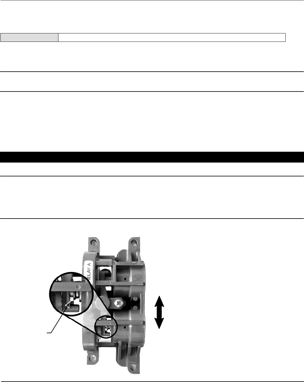
Instruction Manual
D103412X012
Calibration
January 2015
191
Relay
Field Communicator TB > Configure/Setup > Calibration > Relay
Follow the prompts on the Field Communicator display to check relay adjustment. Replace the digital valve controller
cover when finished.
Note
Relay B and C are not user‐adjustable.
Double‐Acting Relay
The double‐acting relay is designated by “Relay A” on a label affixed to the relay itself. For double‐acting actuators, the
valve must be near mid‐travel to properly adjust the relay. The Field Communicator will automatically position the
valve when Relay is selected.
CAUTION
Care should be taken during relay adjustment as the adjustment disc may disengage if rotated too far.
Rotate the adjustment disc, shown in figure 5‐1, until the output pressure displayed on the Field Communicator is
between 50 and 70% of supply pressure. This adjustment is very sensitive. Be sure to allow the pressure reading to
stabilize before making another adjustment (stabilization may take up to 30 seconds or more for large actuators).
Figure 5‐1. Relay A Adjustment (Shroud Removed for Clarity)
ADJUSTMENT DISC
FOR SINGLE‐ACTING DIRECT
RELAYS: ROTATE ADJUSTMENT
DISC IN THIS DIRECTION UNTIL IT
CONTACTS THE BEAM
FOR DOUBLE‐ACTING RELAYS:
ROTATE ADJUSTMENT DISC IN
THIS DIRECTION TO DECREASE
OUTPUT PRESSURE
FOR DOUBLE‐ACTING RELAYS:
ROTATE ADJUSTMENT DISC IN
THIS DIRECTION TO INCREASE
OUTPUT PRESSURE
W9034

Instruction Manual
D103412X012
Calibration
January 2015
192
If the low bleed relay option has been ordered stabilization may take approximately two minutes longer than the
standard relay.
Relay A may also be adjusted for use in single‐acting‐ direct applications. Rotate the adjustment disc as shown in figure
5‐1 for single‐acting direct operation.
Single‐Acting Relays
WARNING
For instrument level PD only:
If the unused port is monitoring pressure, ensure that the pressure source conforms to ISA Standard 7.0.01 and does not
exceed the pressure supplied to the instrument.
Failure to do so could result in personal injury or property damage caused by loss of process control.
Single‐Acting Direct Relay
The single‐acting direct relay is designated by “Relay C” on a label affixed to the relay itself. Relay C requires no
adjustment.
Single‐Acting Reverse Relay
The single‐acting reverse relay is designated by “Relay B” on a label affixed to the relay itself. Relay B is calibrated at the
factory and requires no further adjustment.
Supply Pressure Sensor
Field Communicator TB > Configure/Setup > Calibration > Supply Pressure
Note
The pressure sensor is calibrated at the factory and should not require calibration.
To calibrate the supply pressure sensor, connect an external reference gauge to the output side of the supply
regulator. The gauge should be capable of measuring maximum instrument supply pressure. Select Follow the
prompts on the Field Communicator display to calibrate the instrument's supply pressure sensor.
1. Select a) Zero Only, or b) Zero and Span (gauge required).
a. If Zero Only calibration is selected, adjust the supply pressure regulator to remove supply pressure from the
instrument. Press OK. Once calibration is complete, go to step 5.
b. If Zero and Span calibration is selected, adjust the supply pressure regulator to remove supply pressure from the
instrument. Press OK. Adjust the supply regulator to the maximum instrument supply pressure. Press OK.
Proceed with step 2.

Instruction Manual
D103412X012
Calibration
January 2015
193
2. The following message appears:
Use the Increase and
Decrease selections until
the displayed pressure
matches the instrument
supply pressure.
Press OK when you have read this message.
3. The value of the pressure appears on the display.
4. From the adjustment menu, select the direction and size of adjustment to the displayed value. Selecting large,
medium, and small adjustments causes changes of approximately 3.0 psi/0.207 bar/20.7 kPa, 0.30 psi/0.0207
bar/2.07 kPa, and 0.03 psi/0.00207 bar/0.207 kPa, respectively. Adjust the displayed value until it matches the
supply pressure, select Done and go to step 5.
5. Place the instrument In Service and verify that the displayed pressure matches the measured supply pressure.
Pressure A or B Sensor
Field Communicator TB > Configure/Setup > Calibration > Pressure A
Field Communicator TB > Configure/Setup > Calibration > Pressure B
To calibrate the output pressure sensor, connect an external reference gauge to the output being calibrated. The
gauge should be capable of measuring maximum instrument supply pressure. Select . Follow the prompts on the Field
Communicator display to calibrate the instrument's output pressure sensor.
1. Adjust the supply pressure regulator to the maximum instrument supply pressure. Press OK.
2. The instrument reduces the output pressure to 0. The following message appears.
Use the Increase and
Decrease selections
until the displayed
pressure matches the
output x pressure.
Press OK when you have read the message.
3. The value of the output pressure appears on the display. Press OK to display the adjustment menu.
4. From the adjustment menu, select the direction and size of adjustment to the displayed value. Selecting large,
medium, and small adjustments causes changes of approximately 3.0 psi/0.207 bar/20.7 kPa, 0.30 psi/0.0207
bar/2.07 kPa, and 0.03 psi/0.00207 bar/0.207 kPa, respectively. If the displayed value does not match the output
pressure, press OK, then repeat this step (step 4) to further adjust the displayed value. When the displayed value
matches the output pressure, select Done and go to step 5.

Instruction Manual
D103412X012
Calibration
January 2015
194
5. The instrument sets the output pressure to full supply. The following message appears.
Use the Increase and
Decrease selections
until the displayed
pressure matches the
output x pressure.
Press OK when you have read the message.
6. The value of the output pressure appears on the display. Press OK to display the adjustment menu.
7. From the adjustment menu, select the direction and size of adjustment to the displayed value. If the displayed value
does not match the output pressure, press OK, then repeat this step (step 7) to further adjust the displayed value.
When the displayed value matches the output pressure, select Done and go to step 8.
8. Place the instrument In Service and verify that the displayed pressure matches the measured output pressure.

Instruction Manual
D103412X012
Viewing Device Variables and Diagnostics
January 2015
195
Section 6 Viewing Device Variables and Diagnostics6-6-
View Lists
View Lists allow the values of a set of parameters to be accessed at the same time. View lists are available for the
resource and transducer blocks, and the function blocks.
Resource Block—tables 4‐4 through 4‐7
Transducer Block—tables 4‐15 through 4‐23
AO Function Block—tables 4‐26 through 4‐29
PID Function Block—tables 4‐33 through 4‐37
IS Function Block—tables 4‐41 through 4‐44
OS Function Block—tables 4‐49 through 4‐52
AI Function Block—tables 4‐58 through 4‐61
MAI Function Block—tables 4‐65 through 4‐68
DO Function Block—tables 4‐73 through 4‐76
DI Function Block—tables 4‐82 through 4‐85
Note
Views Lists are used by hosts for efficient monitoring of multiple parameters. Normally you will not be aware of view list usage, as
they are hidden by the host software.
Resource Block
This section contains information on the DVC6200f digital valve controller resource block. The resource block defines
the physical resources of the device. The resource block also handles functionality that is common across multiple
blocks. The block has no linkable inputs or outputs.
Table 6‐1. Resource Block BLOCK_ERR Conditions
Condition Number Condition Name and Description
0Other ‐ Set if a device initialization error occurred.
1Block Configuration Error ‐ Set if FEATURE_SEL, CYCLE_SEL, or CYCLE_TYPE is set incorrectly.
2Link Configuration Error ‐ N/A
3Simulate Active ‐ Indicates that the simulation jumper is in place on the aux terminals. This is not an indication that the I/O
blocks are using simulation data. See AO block parameter SIMULATE [10] and DO block parameter SIMULATE_D [10].
4Local Override ‐ N/A
5Device Fault State ‐ N/A
6Device Needs Maintenance Soon ‐ Indicates a Maintenance PlantWeb Alert condition is active.
7Input failure/process variable had Bad status ‐ N/A
8Output failure ‐ N/A
9Memory failure ‐ Indicates a pending Flash or NVM failure.
10 Lost Static Data ‐ Indicates failure of the memory containing static parameters
11 Lost NV Data ‐ Indicates failure of the memory containing non‐volatile parameters.
12 Readback Check Failed ‐ NA
13 Device Needs Maintenance Now ‐ Indicates a Failed PlantWeb Alert condition is active.
14 Power Up ‐ Indicates the device has been powered up and the Resource Block is not running normally.
15 Out of Service (MSB) ‐ The resource block actual mode is Out of Service.

Instruction Manual
D103412X012
Viewing Device Variables and Diagnostics
January 2015
196
Device Diagnostics
Resource Block Error
(RB > Device Diagnostics > Resource Block Error)
Field Communicator RB > Device Diagnostics > Resource Block Error
Block Error (BLOCK_ERR [6]) indicates an error status associated with hardware or software for the resource block.
Table 6‐1 lists conditions reported in the BLOCK_ERR [6] parameter. Conditions in italics are not applicable for the
resource block and are provided only for your reference.
Device State
Field Communicator RB > Device Diagnostics > Device State
Device State (RS_STATE [7]) indicates the state of the function blocks. Four states are possible:
Initialization—The instrument enters this state upon restart or failure. The function blocks are in the IMan mode.
During the initialization state, all unreported function block alarms are automatically confirmed and acknowledged.
Once the instrument is considered operational, block execution is scheduled and the instrument state moves to
Online.
Online—The instrument will be in this state if it is operational. The function blocks are initially in the Auto mode, but
can be changed to a higher level mode.
Standby—The instrument enters this state if the resource block mode is Out of Service (OOS). In this state all
function block modes are forced to Out of Service. The transducer block mode is not affected. When the resource
block mode is changed to Auto, the instrument state moves to Online.
Failure— The instrument moves to this state whenever a hardware or memory failure is detected which would
prevent reliable operation. All function blocks and the transducer block modes are Out of Service.
Write Lock
Field Communicator RB > Device Diagnostics > Write Lock
Write Alarm: Alarm State
Write Lock
Write Lock (WRITE_LOCK [34]) determines if writes are permissible to other device parameters. The Soft Write Lock
feature must be selected to be able to use Write Lock (see Selecting Features). When Write Lock is set to Locked, no
writes are permitted to any parameters within the device except to set Write Lock to Not Locked. When locked, the
block functions normally, updating inputs and outputs and executing algorithms. When Write Lock is set to Not
Locked, the Write Alarm alert is active.

Instruction Manual
D103412X012
Viewing Device Variables and Diagnostics
January 2015
197
Block Alarm
Field Communicator RB > Device Diagnostics > Block Alarm
The Block Alarm (BLOCK_ALM [36]) is used for all configuration, hardware, connection failure or system problems in
the block.
Block Alarm: Alarm State
Block Alarm: Alarm State (BLOCK_ALM. ALARM_STATE [36.2]) indicates the state of the Block Alarm. Five states are
possible:
Undefined
Clear reported
Clear not reported
Active reported
Active not reported
Block Alarm: Unacknowledged
Block Alarm: Unacknowledged (BLOCK_ALARM. UNACKNOWLEDGED [36.1])
1 = Undefined
2 = Acknowledged
3 = Unacknowledged
Maintenance
Field Communicator RB > Device Diagnostics > Maintenance
Restart Actions
WARNING
Restarting the instrument may cause loss of process control. To avoid personal injury and property damage caused by the
release of pressure of process fluid, isolate the valve from the process and equalize pressure on both sides of the valve or
bleed off the process fluid.
You can restart the instrument to reset parameters, links, etc. within the instrument. However, due to the effect that a
restart can have on the instrument, and therefore the control loop, restarting the instrument should be used
cautiously and only as a last measure. The following procedure describes how to use Restart Options to restart the
instrument with a Field Communicator. You can also restart the instrument using ValveLink software or from a host
system using the Restart method included with the device description (DD) software.
You can restart the instrument any time it is connected to an active segment.
Field Communicator RB > Device Diagnostics > Maintenance > Restart Actions
1. Restart informs you about what can happen when an instrument restart is performed. Select Yes to continue, or No
to abort without restarting.
2. Select the desired restart action or select EXIT to exit Restart. Select Help (not the Help button) to get information
on restart actions.

Instruction Manual
D103412X012
Viewing Device Variables and Diagnostics
January 2015
198
There are two different restarts: Restart Processor, and Restart with Defaults:
When selecting either of these options, Restart informs you of the consequences of this action and asks if you want to
continue. Select Yes to perform the restart action, select No to select another action or exit. Restart informs you when
the restart is completed. You must acknowledge the message to continue.
Restart Processor—Performing a Restart Processor has the same effect as removing power from the instrument and
re‐applying power. Configuration and calibration do not change.
Restart with Defaults—Performing a Restart with Defaults should be done with care. This restart resets most of the
static and non‐volatile parameters for all of the blocks in the instrument to their initial value, as listed in table 4‐2. After
a Restart with Defaults, you should place the instrument in service (the transducer block mode to auto) and run Device
Setup and download the instrument configuration from the control system to properly setup the instrument. You also
may need to re‐establish communication links and trends.
Fault State—Fault State (FAULT_STATE [28]), when active, indicates that the resource block is currently forcing the
output block to perform its FSTATE action. Selecting Fault State enables the ability to manually set and clear the
fault state.
Set Fault State—Selecting Set Fault State (SET_FSTATE [29]) changes the Fault State (FAULT_STATE [28]) to Active.
Setting Set FState (SET_FSTATE [29]) to SET manually places the instrument in the fault state.
Clear Fault State—Setting Clear FState (CLR_FSTATE [30]) to CLEAR clears the device fault state, if no faults are
currently active. You can test the actions the output blocks will perform by manually setting fault state active.
Device Variables
Instrument
Field Communicator RB > Device Variables > Instrument
The following parameters are contained in the the Instrument menu of the resource block.
Identification
Device ID—The 32 character Device ID (DEVICE_ID [54]).
Electronics Serial Number—The Electronics Serial Number (ELECTRONICS_SN [49]) set at the factory.
Factory Serial Number—The Factory Serial Number (FACTORY_SN [50]) is the instrument serial number set at the
factory.
Field Serial Number—The Field Serial Number (FIELD_SN [51]) is the serial number of the valve and actuator on
which the instrument is mounted.
Tag Description—The Tag Description (TAG_DESC [2]) is unique description of each block within the digital valve
controller, used to describe the intended application for the block. Follow the prompts on the Field Communicator
to enter an up to 32 character description for the block in the Tag Description field. (This parameter is read/write.)
Strategy—Strategy (STRATEGY [3]) permits strategic grouping of blocks so the operator can identify where the
block is located. The blocks may be grouped by plant area, plant equipment, etc. Enter a value between 0 and
65535 in the Strategy field.

Instruction Manual
D103412X012
Viewing Device Variables and Diagnostics
January 2015
199
Manufacturer—Manufacturer Identification (MANUFAC_ID [10]) identifies the manufacturer of the instrument. It is
used by the host system to locate the DD file for the device. For Fisher the Manufacturer ID is 0x5100.
Device Type—Device Type (DEV_TYPE [11]) identifies the type of device. It is used by the host system to locate the
DD file for the device. For a DVC6200f digital valve controller with Standard Control the device type is 0x4602.
Version
Device Revision—Device Revision (DEV_REV [12]) identifies the device revision number. It is used by the host system
to locate the DD file for the device.
Firmware Revision—Firmware Revision (FIRMWARE_REV_ALL [47.6]) shows all device firmware revisions currently in
operation.
Standby Firmware Revision—Standby Firmware Revision (STBY_FIRMWARE_REV_ALL [55.6]) shows all device
firmware revisions currently in standby.
Hardware Revision—Hardware Revision(HARDWARE_REV[48]) identifies the electronic hardware revision.
ITK Version—ITK Version (ITK_VER [41]) identifies the major version of the Interoperability Tester used by the
Fieldbus Foundation in certifying the device as interoperable. This device revision meets the requirements of
version 5.
Options
Field Communicator RB > Device Variables > Options
The following parameters are contained in the the Options menu of the resource block.
Diagnostic Options—Diagnostic Options (DIAG_OPTIONS [45]) shows the diagnostic options available in the
instrument.
Function Block Options—Function Block Options (FB_OPTIONS [44]) shows which function blocks are licenced and
enabled in the instrument.
Miscellaneous Options—Miscellaneous Options (MISC_OPTIONS [46]) indicates which miscellaneous licensing
options are enabled.
Features Available—Features (FEATURES [17]) shows the supported resource block options.
DD Information
Field Communicator RB > Device Variables > DD Information
DD Information contains information about the Device Description (DD).
Transducer Block
This section contains information on the DVC6200f digital valve controller transducer block. Descriptions of all
transducer block parameters are included. The transducer block decouples function blocks from the local output
functions required to command output hardware. The transducer block typically contains setup and calibration
information.

Instruction Manual
D103412X012
Viewing Device Variables and Diagnostics
January 2015
200
Device Diagnostics
Active PlantWeb Alerts
Field Communicator TB > Device Diagnostic > Active PlantWeb Alerts
To view the active PlantWeb alerts select Active PlantWeb Alerts.
Alert Conditions
Field Communicator TB > Device Diagnostic > Active Conditions
Instrument Alert Conditions, when enabled, detect many operational and performance issues that may be of interest.
The alert conditions for each group of alerts are listed below. If there are no alerts active for a particular group the
group will not be displayed on the Field Communicator.
Electronics—if an electronics alert is active it will appear under ELECT ALERTS
Drive Current
Drive Current Alert—This alert is active when the difference between the expected Drive Current and the actual Drive
Current has exceeded the Drive Current Alert Time.
Drive Signal
Drive Signal Alert—The Drive Signal Alert is active if one of the following conditions exist:
Where Zero Power Condition is defined as closed:
Drive Signal < 10% and Calibrated Travel > 3%
Drive Signal > 90% and Calibrated Travel < 97%
Where Zero Power Condition is defined as open:
Drive Signal < 10% and Calibrated Travel < 97%
Drive Signal > 90% and Calibrated Travel > 3%
Processor Impaired
Program Memory Alert—This alert is active if a pending flash or NVM failure is present.
Static Memory Alert—This alert is active when there is a failure of the FRAM memory where static parameters are
stored.
Processor Alert—This alert is active when there is a failure of the main processor.
I/O Processor Alert—This alert is active when there is a failure of the I/O processor.
Configuration—If a configuration alert is active it will appear under CONFIG ALERTS
Output Block Timeout
Output Block Timeout Alert—This alert is active if the output block has not executed for a period of time longer than
the configured timeout.

Instruction Manual
D103412X012
Viewing Device Variables and Diagnostics
January 2015
201
Blocks Set to Default
Blocks Set to Default Alert—This alert is active if the resource block has undergone Restart with Defaults. This will stay
active until the transducer block is changed from Out of Service.
Sensor—If a configuration alert is active it will appear under SENSOR ALERTS
Travel Sensor
Travel Sensor—This alert is active if the Travel Sensor reading is outside the functional range, or the sensor becomes
disconnected.
Pressure Sensors
Pressure A Sensor Alert—This alert is active if the Port A Pressure Sensor reading is outside the functional range.
Pressure B Sensor Alert—This alert is active if the Port B Pressure Sensor reading is outside the functional range.
Supply Pressure Sensor Alert—This alert is active if the Pressure Sensor reading is outside the functional range.
Pressure Fallback
Pressure Fallback Alert—This alert is active if a travel sensor failure or a gross travel deviation has resulted in fallback to
pressure control.
Temperature Sensor
Temperature Sensor Alert—This alert is active if the temperature sensor reading is outside the functional range of the
sensor.
Environment—If an environment alert is active it will appear under ENVIRO ALERTS
Supply Pressure
Supply Pressure Hi Alert—This alert is active if the supply pressure exceeds the Supply Pressure Hi Alert.
Supply Pressure Lo Alert—This alert is active if the supply pressure exceeds the Supply Pressure Lo Alert.
Temperature Limit
Temperature Hi Alert—This alert is active if the temperature is greater than the Temperature Hi Alert Point.
Temperature Lo Alert—This alert is active if the temperature is greater than the Temperature Lo Alert Point.
Travel—If a travel alert is active it will appear under TRAVEL ALERTS
Travel Deviation
Travel Deviation Alert—This alert is active if the Travel deviation exceeds the Travel Deviation Alert Point by more than
the Travel Deviation Time.
Travel Limit
Travel Limit Hi Hi Alert—This alert is active if Travel exceeds the Travel Limit Hi Hi Alert point.
Travel Limit Lo Lo Alert—This alert is active if Travel is lower than the Travel Limit Lo Lo Alert point.
Travel Hi/Lo
Travel Limit Hi Alert—This alert is active if Travel exceeds the Travel Limit Hi Alert point.
Travel Limit Lo Alert—This alert is active if Travel is lower than the Travel Limit Lo Alert point.
Proximity—If a proximity alert is active it will appear under PROX ALERTS
Travel Open
Travel Open Alert—This alert is active if the travel is greater than the travel open alert point.

Instruction Manual
D103412X012
Viewing Device Variables and Diagnostics
January 2015
202
Travel Closed
Travel Closed Alert—This alert is active if the travel is greater than the travel closed alert point.
Proximity
Proximity Hi Hi Alert—This alert is active if the Travel is within the detection band set by the Travel Hi Hi Alert Point
and the Travel Hi Hi Deadband.
Proximity Hi Alert—This alert is active if the Travel is within the detection band set by the Travel Hi Alert Point and the
Travel Hi Deadband.
Proximity Lo Alert—This alert is active if the Travel is within the detection band set by the Travel Lo Alert Point and the
Travel Lo Deadband.
Proximity Lo Lo Alert—This alert is active if the Travel is within the detection band set by the Travel Lo Lo Alert Point
and the Travel Lo Lo Deadband.
Travel History—If a travel history alert is active it will appear under TVL HIST ALERTS
Cycle Counter
Cycle Counter Alert—This alert is active if the Cycle Counter exceeds the Cycle Count Alert Point.
Travel Accumulator
Travel Accumulator Alert—This alert is active if the Travel Accumulator exceeds the Travel Accumulator Alert Point.
Performance—if a performance alert is active it will appear under PERF ALERTS
Performance Critical
Performance Critical Alert—This alert is active if the instrument is no longer able to control the valve or performance
has been dramatically reduced.
Performance Reduced Alert—This alert is active if the instrument has detected a reduction in performance.
Performance Information Alert—This alert is active if the instrument has detected a condition that may pertain to
control performance.
Status
Field Communicator TB > Device Diagnostic > Status
Self Test Status
Integrator Suspended—The integrator function is temporarily suspended. The integrator is suspended if any of the
following conditions are met:
The setpoint and actual travel are greater than 98% or less than 2%.
The set point is in cutoff
The Transducer block is Out of Service (OOS)
Integrator Limited Lo—Indicates the integrator reached its limit and cannot move the valve any further. High valve
friction may cause this situation.
Integrator Limited Hi—Indicates the integrator reached its limit and cannot move the valve any further. High valve
friction may cause this situation.

Instruction Manual
D103412X012
Viewing Device Variables and Diagnostics
January 2015
203
Travel Sensor Span Error—Indicates that span between the endpoints of travel are not far enough apart. This error is
reported during automatic calibration.
MLFB Error—Indicates that the Minor Loop Feedback sensor gave a non‐valid value during automatic calibration.
Travel Sensor Hi Error—Indicates the travel sensor has reported a travel position that is significantly above the normal
operating range, and has failed.
Travel Sensor Lo Error—Indicates the travel sensor has reported a travel position that is significantly below the normal
operating range, and has failed.
Pressure B Sensor Failure—Indicates the pressure sensor is reporting a pressure that is significantly outside of the normal
operating pressure, and has failed.
Pressure A Sensor Failure—Indicates the pressure sensor is reporting a pressure that is significantly outside of the normal
operating pressure, and has failed.
Supply Sensor Failure—Indicates the pressure sensor is reporting a pressure that is significantly outside of the normal
operating pressure, and has failed.
IOP Failure—Indicates the I/O processor has failed.
Drive Current Alert—Indicates that the Drive Current has exceeded the Drive Current Alert Point for more than the Drive
Current Alert Time.
Simulate Jumper ON—Indicates the simulate jumper is connected to the DVC6200f between the two AUX terminals.
Block Error
Table 6‐2 lists conditions reported in the BLOCK_ERR [6] and XD_ERROR [11] parameters. Conditions in italics are not
applicable for the transducer block and are provided only for your reference.
Table 6‐2. Transducer Block BLOCK_ERR and XD_ERROR Conditions
Condition Number Condition Name and Description
0Other ‐ (N/A)
1Block Configuration Error ‐ Indicates that one of the following parameters have been configured out of the proper range: 15,
16, 47.1, 47.2, 46.3, 46.5, 42.7, 42.8.
2Link Configuration Error ‐ (N/A)
3Simulate Active ‐ Indicates that alerts are being simulated. This is not an indication that the I/O blocks are using simulation
data. See AO block parameter SIMULATE [10] and DO block parameter SIMULATE_D [10].
4Local Override ‐ (N/A)
5Device Fault State - (NA)
6Maintenance Needed Soon ‐ (N/A)
7Input failure/process variable has Bad status ‐ (N/A)
8Output failure ‐ (N/A)
9Memory failure ‐ (N/A)
10 Lost Static Data ‐ Indicates that manufacturing functional or thermal tests were incomplete
11 Lost NV Data ‐ (N/A)
12 Readback Check Failed ‐ (N/A)
13 Device Needs Maintenance Now ‐ Indicates that manufacturing functional or thermal tests were incomplete
14 Power Up ‐ (N/A)
15 Out of Service ‐ Indicates Out of Service Mode.

Instruction Manual
D103412X012
Viewing Device Variables and Diagnostics
January 2015
204
Device Record
Field Communicator TB > Device Diagnostic > Device Record
The following parameters are contained in the Device Record menu of the transducer block.
Maximum Recorded Temperature—Maximum Recorded Temperature (TEMP_MAX [86.1]) shows the maximum
temperature the instrument has experienced since installation.
Maximum Recorded Temperature Time—Maximum Recorded Temperature Time (TEMP_MAX_TIME [86.2]) shows
the date and time when the Temperature Maximum occurred.
Minimum Recorded Temperature—Minimum Recorded Temperature (TEMP_MIN [86.3]) shows the minimum
temperature the instrument has experienced since installation.
Minimum Recorded Temperature Time—Minimum Recorded Temperature Time (TEMP_MIN_TIME [86.4]) shows
the date and time when the Temperature Minimum occurred.
Maximum Recorded Supply Pressure—Maximum Recorded Supply Pressure (SUPPLY_PRESS_MAX [86.5]) shows the
maximum supply pressure the instrument has experienced since installation.
Maximum Recorded Supply Pressure Time—Maximum Recorded Supply Pressure Time (SUPP_PRESS_MAX_TIME
[86.6]) shows the date and time when the Supply Pressure Maximum occurred.
Minimum Recorded Supply Pressure—Minimum Recorded Supply Pressure (SUPP_PRESS_MIN [86.7]) shows the
minimum supply pressure the instrument has experienced since installation.
Minimum Recorded Supply Pressure Time—Minimum Recorded Supply Pressure Time (SUPP_PRESS_MIN_TIME
[86.8]) shows the date and time when the Supply Pressure Minimum occurred.
Stroking the Digital Valve Controller Output
Field Communicator TB > Device Diagnostic > Stroke Valve
Stroke Valve is used to confirm proper valve operation. Follow the prompts on the Field Communicator display to
select from the following: Done, Ramp Open, Ramp Closed, Ramp to Target, Step to Target, and Stop.
Done—Select this if you are done. All ramping is stopped when DONE is selected.
Ramp Open—ramps the travel toward open at the rate of 1.0% per second of the ranged travel.
Ramp Closed—ramps the travel toward closed at the rate of 1.0% per second of the ranged travel.
Ramp to Target—ramps the travel to the specified target at the rate of 1.0% per second of the ranged travel.
Step to Target—steps the travel to the specified target.
Stop—stops the command.

Instruction Manual
D103412X012
Viewing Device Variables and Diagnostics
January 2015
205
Trend
Field Communicator TB > Device Diagnostic > Trend
Trend chart of Setpoint (FINAL_VALUE.VALUE [13.2]), Travel (TRAVEL.VALUE [34.2]), and Pressure A
(PRESSURE_A.VALUE [36.2]).
Device Variables
Field Communicator TB > Device Variables
All Block Modes
Block Mode: Target
The Target (TARGET [5.1]) mode is the mode requested by the user or host system. Generally, only one mode is
allowed to be set, and it must be a permitted mode as defined by the permitted attribute of the mode parameter.
Additionally, all cascade targets (Cas, Rcas) must have AUTO set.
Block Mode: Actual
This is the current mode of the block. The actual (ACTUAL [5.2]) mode may differ from the target mode due to
operating conditions of the block.
Note
Block Mode:Actual drops the AUTO bit for the cascade targets. For example, target mode might have Cas and Auto set, but actual
mode will only have Cas set.
Block Mode: Permitted
The permitted (PERMITTED [5.3]) mode defines the modes allowed for the block. This is set by the user or host system
but is restricted by the instrument to modes supported by the instrument for the particular block. Any change request
to the Target or Normal attribute is checked against the permitted attribute to ensure the requested mode is
permitted. When setting the Permitted mode, there is no check against any of the other attributes (Normal or Target
modes). Therefore, the normal or target mode attributes may have a value that is not permitted because the
permitted attribute was modified after the Normal or Target mode was set. This will have no effect on the instrument
until the user attempts to modify the Target or Normal mode. At this time these attributes are tested against the
Permitted modes, thus the user cannot change the Normal or Target modes to what was formerly permitted.
Block Mode: Normal
The normal (NORMAL [5.4]) mode is the mode the block should be in during normal operating conditions. The normal
mode is set by the user or host system and can only be set to a permitted mode (see permitted mode). The user or
host system can compare the actual mode to the normal mode and, based on the results, determine if the block is
operating normally.

Instruction Manual
D103412X012
Viewing Device Variables and Diagnostics
January 2015
206
AO Control - Pre‐Characterization
Setpoint
Setpoint (FINAL_VALUE.VALUE [13.2]) shows the value of the setpoint in % (percent) of ranged travel or pressure.
Setpoint is used for both travel and pressure control. This parameter will be written directly if the transducer block is in
MAN mode, or will be written automatically by the AO block if the transducer block is in AUTO mode.
Setpoint Status
Shows the Foundation Fieldbus status of Setpoint Value (FINAL_VALUE.STATUS [13.2]); Good, Uncertain, or Bad.
Travel (DeChar)
Travel (FINAL_POSITION_VALUE.VALUE [17.2]) shows the value of the travel in % (percent) of ranged travel. Travel
always represents how far the valve is open.
AO Control‐Post Characterization
Travel Target
Travel target is the output from the characterization function.
Travel
Travel (TRAVEL.VALUE [34.2]) displays the actual position of the valve in percent (%) of calibrated travel.
Travel Status
Shows the Foundation Fieldbus status of Travel Value (TRAVEL.STATUS [34.1]); Good, Uncertain, or Bad.
DO Control
Setpoint(D)
Discrete Setpoint (SETPOINT_D.VALUE [32.2]) shows the value of the setpoint in discrete values.
0 = closed, 1 = open, 5, 10, 15... = setpoint in 5% units. This parameter will be written directly if the transducer block is
in MAN mode, or will be written automatically by the DO block if the transducer block is in AUTO mode.
Travel(D)
Travel (TRAVEL_D.VALUE [33.2]) shows the value of the setpoint in discrete values.
0 = closed, 1 = open, 5, 10, 15... = setpoint in 5% units.
Input Characterization
Input Characterization (INPUT_CHAR [50]) defines the relationship between the setpoint specified by the output
function block and the desired valve position.

Instruction Manual
D103412X012
Viewing Device Variables and Diagnostics
January 2015
207
Travel/Pressure State
Travel/Pressure State (TVL_PRESS.STATE [41.2]) indicates if the instrument is being used for travel control (position
control) or as an I/P (pressure control).
PD Inside Status
PD Inside Status shows the status of Performance Diagnostics.
Protection
Indicates the status of Protection.
Drive Signal
Drive Signal (DRIVE_SIGNAL [53]) indicates the drive signal, as a percentage of the maximum drive available, going to
the I/P converter from the printed wiring board. In most applications, the drive signal ranges between 50% and 75% of
the maximum drive signal.
Temperature
Temperature (TEMPERATURE [48]) displays the internal temperature of the instrument in either degrees Fahrenheit or
Celsius.
Cycle Counter
Cycle Counter (CYCLE_COUNT [73]) records the number of times the travel changes direction. The change in direction
must occur after the deadband has been exceeded before it can be counted as a cycle.
Travel Accumulator
Travel Accumulator (TRAVEL_ACCUM [72]) indicates the total change in travel, in percent of ranged travel. The
accumulator only increments when travel exceeds the deadband. Then the greatest amount of change in one
direction from the original reference point (after the deadband has been exceeded) will be added to the Travel
Accumulator.
Travel Count
Travel Count (TVL_COUNT [43.1]) is the Travel Sensor readback displayed in A/D counts.

Instruction Manual
D103412X012
Viewing Device Variables and Diagnostics
January 2015
208
Pressures
Supply
Supply (SUPPLY_PRESSURE_VALUE [35.2]) shows the value of the supply pressure in psi, bar, kPa, inHg, inH2O, or
kg/cm2.
Pressure A
Pressure A (PRESSURE_A.VALUE [36.2]) shows the value of Output Pressure A in psi, bar, kPa, inHg, inH2O, or kg/cm2.
Pressure B
Pressure B (PRESSURE_B.VALUE [37.2]) shows the value of Output Pressure B in psi, bar, kPa, inHg, inH2O, or kg/cm2.
A Minus B
A Minus B (PRESSURE_DIFF.VALUE [38.2]) shows the value of the output pressure differential in psi, bar, kPa, inHg,
inH2O, or kg/cm2.

Instruction Manual
D103412X012
Maintenance and Troubleshooting
January 2015
209
Section 7 Maintenance and Troubleshooting7-7-
The DVC6200f digital valve controller enclosure is rated Type 4X and IP66, therefore periodic cleaning of internal
components is not required. If the DVC6200f is installed in an area where the exterior surfaces tend to get heavily
coated or layered with industrial or atmospheric contaminants, however, it is recommended that the vent (key 52) be
periodically inspected to ensure it is fully open. If the vent appears to be clogged, it can be removed, cleaned and
replaced. Lightly brush the exterior of the vent to remove contaminants and run a mild water/detergent solution
through the vent to ensure it is fully open. Allow the vent to dry before reinstalling.
WARNING
Personal injury or property damage can occur from cover failure due to overpressure. Ensure that the housing vent
opening is open and free of debris to prevent pressure buildup under the cover.
WARNING
To avoid static discharge from the plastic cover when flammable gases or dust are present, do not rub or clean the cover
with solvents. To do so could result in a spark that may cause the flammable gases or dust to explode, resulting in personal
injury or property damage. Clean with a mild detergent and water only.
WARNING
Avoid personal injury or property damage from sudden release of process pressure or bursting of parts. Before performing
any maintenance procedures on the DVC6200f digital valve controller:
Always wear protective clothing, gloves, and eyewear.
Do not remove the actuator from the valve while the valve is still pressurized.
Disconnect any operating lines providing air pressure, electric power, or a control signal to the actuator. Be sure the
actuator cannot suddenly open or close the valve.
Use bypass valves or completely shut off the process to isolate the valve from process pressure. Relieve process pressure
from both sides of the valve.
Vent the pneumatic actuator loading pressure and relieve any actuator spring precompression.
Use lock‐out procedures to be sure that the above measures stay in effect while you work on the equipment.
Check with your process or safety engineer for any additional measures that must be taken to protect against process
media.
WARNING
When using natural gas as the supply medium, or for explosion proof applications, the following warnings also apply:
Remove electrical power before removing the housing cap. Personal injury or property damage from fire or explosion
may result if power is not disconnected before removing the cap.
Remove electrical power before disconnecting any of the pneumatic connections.
When disconnecting any of the pneumatic connections or any pressure retaining part, natural gas will seep from the
unit and any connected equipment into the surrounding atmosphere. Personal injury or property damage may result

Instruction Manual
D103412X012
Maintenance and Troubleshooting
January 2015
210
from fire or explosion if natural gas is used as the supply medium and appropriate preventive measures are not taken.
Preventive measures may include, but are not limited to, one or more of the following: ensuring adequate ventilation
and the removal of any ignition sources.
Ensure that the cover is correctly installed before putting this unit back into service. Failure to do so could result in
personal injury or property damage from fire or explosion.
CAUTION
When replacing components, use only components specified by the factory. Always use proper component replacement
techniques, as presented in this manual. Improper techniques or component selection may invalidate the approvals and
the product specifications, as indicated in table 1‐1, and may also impair operations and the intended function of the
device.
Because of the diagnostic capability of the DVC6200f, predictive maintenance is available through the use of ValveLink
software. Using the digital valve controller, valve and instrument maintenance can be enhanced, thus avoiding
unnecessary maintenance. For information on using ValveLink software, refer to the ValveLink software online help.
Removing the Magnetic Feedback Assembly
To remove the magnet assembly from the actuator stem, perform the following basic steps.
1. Make sure that the valve is isolated from the process.
2. Remove the instrument terminal box cover.
3. Disconnect the field wiring from the terminal board.
4. Shut off the instrument air supply.
5. Disconnect the pneumatic tubing and remove the DVC6200f or the DVC6215 from the actuator.
6. Remove the screws holding the magnet assembly to the connector arm.
When replacing the instrument, be sure to follow the mounting guidelines in the Installation section. Setup and
calibrate the instrument prior to returning to service.
Module Base Maintenance
The digital valve controller contains a module base consisting of the I/P converter, printed wiring board assembly, and
pneumatic relay. The module base may be easily replaced in the field without disconnecting field wiring or tubing.
Tools Required
Table 7‐1 lists the tools required for maintaining the DVC6200f digital valve controller.
Table 7‐1. Tools Required
Tool Size Component
Phillips Screwdriver
Hex key
Hex key
Hex key
Hex key
5 mm
1.5 mm
2.5 mm
6 mm
Relay, printed wiring board assembly, and cover screws
Terminal box screw
Terminal box cover screw
I/P converter screws
Module base screws

Instruction Manual
D103412X012
Maintenance and Troubleshooting
January 2015
211
Component Replacement
When replacing any of the components of the DVC6200f, the maintenance should be performed in an instrument
shop whenever possible. Make sure that the electrical wiring and pneumatic tubing is disconnected prior to
disassembling the instrument.
Removing the Module Base
Refer to figure 8‐2 or 8‐4 for key number locations.
WARNING
To avoid personal injury or equipment damage from bursting of parts, turn off the supply pressure to the digital valve
controller and bleed off any excess supply pressure before attempting to remove the module base assembly from the
housing.
1. Unscrew the four captive screws in the cover (key 43) and remove the cover from the module base (key 2).
2. Using a 6 mm hex socket wrench, loosen the three‐socket head screws (key 38). These screws are captive in the
module base by retaining rings (key 154).
Note
The module base is linked to the housing by two cable assemblies. Disconnect these cable assemblies after you pull the module
base out of the housing.
CAUTION
To avoid affecting performance of the instrument, take care not to damage the module base seal or guide surface. Do not
bump or damage the bare connector pins on the PWB assembly. Damaging either the module base or guide surface may
result in material damage, which could compromise the instruments ability to maintain a pressure seal.
3. Pull the module base straight out of the housing (key 1). Once clear of the housing, swing the module base to the
side of the housing to gain access to the cable assemblies.
4. The digital valve controller has two cable assemblies, shown in figure 7‐1, which connect the module base, via the
printed wiring board assembly, to the travel sensor and the terminal box. Disconnect these cable assemblies from
the printed wiring board assembly on the back of the module base.
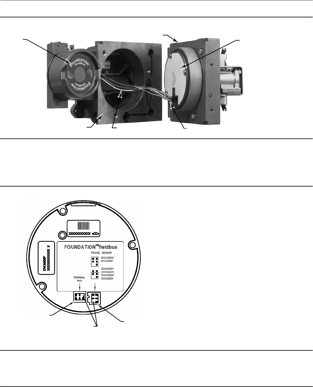
Instruction Manual
D103412X012
Maintenance and Troubleshooting
January 2015
212
Figure 7‐1. Printed Wiring Board Cable Connections
HOUSING
W9924‐1
CABLE TO TRAVEL SENSOR
PRINTED WIRING
BOARD
ASSEMBLY
CABLE
TO TERMINAL BOX
TERMINAL
BOX MODULE BASE ASSEMBLY
Replacing the Module Base
Refer to figure 8‐2 or 8‐4 for key number locations. Refer to figure 7‐2 for a view of the back of the PWB assembly
sub‐module.
Figure 7‐2. Back View of PWB Assembly Sub‐Module
GE39341
PINS REMOVED FOR
CONNECTOR KEYING
TERMINAL BOX
CONNECTOR TRAVEL SENSOR CONNECTOR
S
S
Note
To avoid affecting performance of the instrument, inspect the guide surface on the module and the corresponding seating area in
the housing before installing the module base assembly. These surfaces must be free of dust, dirt, scratches, and contamination.
Ensure the module base seal is in good condition. Do not reuse a damaged or worn seal.

Instruction Manual
D103412X012
Maintenance and Troubleshooting
January 2015
213
1. Ensure the module base seal (key 237) is properly installed in the housing (key 1). Ensure the O‐ring (key 12) is in
place on the module base assembly.
2. Connect the terminal box connector to the PWB assembly (key 50). Orientation of the connector is required.
3. Connect the travel sensor connector to the PWB assembly (key 50). Orientation of the connector is required.
4. Insert the module base (key 2) into the housing (key 1).
5. Install three socket head screws (key 38) in the module base into the housing. If not already installed, press three
retaining rings (key 154) into the module base. Evenly tighten the screws in a crisscross pattern to a final torque of
16 Nm (138 lbfin).
CAUTION
Personal injury, property damage, or disruption of process control can result if the cable assemblies/wiring are damaged
when attaching the cover to the module base assembly
Ensure that the cable assemblies/wiring are positioned in the cavity of the module base so they do not get compressed or
damaged when attaching the cover to the module base assembly in step 6.
6. Attach the cover (key 43) to the module base assembly.
Submodule Maintenance
The digital valve controller's module base contains the following submodules: I/P converter, PWB assembly, and
pneumatic relay. If problems occur, these submodules may be removed from the module base and replaced with new
submodules. After replacing a submodule, the module base may be put back into service.
CAUTION
Exercise care when performing maintenance on the module base. Reinstall the cover to protect the I/P converter and
gauges when servicing other submodules.
In order to maintain accuracy specifications, do not strike or drop the I/P converter during submodule maintenance.
I/P Converter
Refer to figure 8‐2 or 8‐4 for key number locations. The I/P converter (key 41) is located on the front of the module
base.
Note
After I/P converter submodule replacement, calibrate the digital valve controller to maintain accuracy specifications.
Replacing the I/P Filter
A screen in the supply port beneath the I/P converter serves as a secondary filter for the supply medium. To replace this
filter, perform the following procedure:
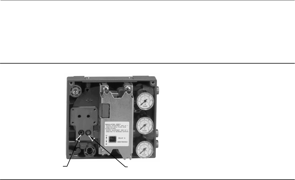
Instruction Manual
D103412X012
Maintenance and Troubleshooting
January 2015
214
1. Remove the I/P converter (key 41) and shroud (key 169) as described in the Removing the I/P Converter procedure.
2. Remove the screen (key 231) from the supply port.
3. Install a new screen in the supply port as shown in figure 7‐3.
4. Inspect the O‐ring (key 39) in the I/P output port. if necessary, replace it.
5. Reinstall the I/P converter (key 41) and shroud (key 169) as described in the Replacing the I/P Converter procedure.
Figure 7‐3. I/P Filter Location
SCREEN (FILTER) LOCATED IN I/P
CONVERTER SUPPLY PORT
O‐RING LOCATED IN I/P
CONVERTER OUTPUT PORT
W8072
Removing the I/P Converter
1. Remove the front cover (key 43), if not already removed.
2. Refer to figure 7‐4. Using a 2.5 mm hex socket wrench, remove the four socket‐head screws (key 23) that attach the
shroud (key 169) and I/P converter (key 41) to the module base (key 2).
3. Remove the shroud (key 169); then pull the I/P converter (key 41) straight out of the module base (key 2). Be
careful not to damage the two electrical leads that come out of the base of the I/P converter.
4. Ensure that the O‐ring (key 39) and screen (key 231) stay in the module base and do not come out with the I/P
converter (key 41).
Replacing the I/P Converter
1. Refer to figure 7‐3. Inspect the condition of the O‐ring (key 39) and screen (key 231) in the module base (key 2).
Replace them, if necessary. Apply silicone lubricant to the O‐rings.
2. Ensure the two boots (key 210) shown in figure 7‐4 are properly installed on the electrical leads.
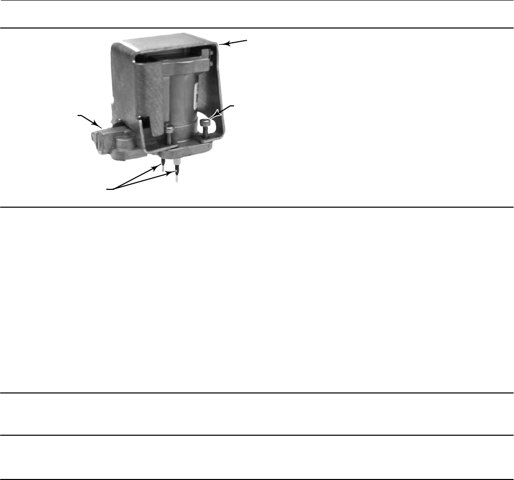
Instruction Manual
D103412X012
Maintenance and Troubleshooting
January 2015
215
W9328
SOCKET‐HEAD
SCREWS (4)
(KEY 23)
SHROUD
(KEY 169)
I/P CONVERTER
(KEY 41)
BOOTS
(KEY 210)
Figure 7‐4. I/P Converter
3. Install the I/P converter (key 41) straight into the module base (key 2), taking care that the two electrical leads feed
into the guides in the module base. These guides route the leads to the printed wiring board assembly submodule.
4. Install the shroud (key 169) over the I/P converter (key 41).
5. Install the four socket‐head screws (key 23) and evenly tighten them in a crisscross pattern to a final torque of 1.6
Nm (14 lbfin).
6. After replacing the I/P converter, calibrate travel or perform touch‐up calibration to maintain accuracy
specifications.
Printed Wiring Board (PWB) Assembly
Refer to figure 8‐2 or 8‐4 for key number locations. The PWB assembly (key 50) is located on the back of the module
base assembly (key 2).
Note
The DVC6200f PWB assembly must be firmware revision 2.0 or later.
Note
If the PWB assembly submodule is replaced, calibrate and configure the digital valve controller to maintain accuracy specifications.
Removing the Printed Wiring Board Assembly
1. Separate the module base from the housing by performing the Removing the Module Base procedure.
2. Remove three screws (key 33).
3. Lift the PWB assembly (key 50) straight out of the module base (key 2).
4. Ensure that the O‐rings (key 40) remain in the pressure sensor bosses on the module base assembly (key 2) after the
PWB assembly (key 50) has been removed.
Replacing the Printed Wiring Board Assembly
1. Apply silicone lubricant to the pressure sensor O‐rings (key 40) and install them on the pressure sensor bosses in the
module base assembly.

Instruction Manual
D103412X012
Maintenance and Troubleshooting
January 2015
216
2. Properly orient the PWB assembly (key 50) as you install it into the module base. The two electrical leads from the
I/P converter (key 41) must guide into their receptacles in the PWB assembly and the pressure sensor bosses on the
module base must fit into their receptacles in the PWB assembly.
3. Push the PWB assembly (key 50) into its cavity in the module base.
4. Install and tighten three screws (key 33) to a torque of 1 Nm (10.1 lbfin).
5. Reassemble the module base to the housing by performing the Replacing the Module Base procedure.
6. Setup and calibrate the digital valve controller.
Note
Calibration is required for either Travel or Pressure Control after PWB Assembly replacement.
Note that only one calibration is needed, depending on control selection.
Pneumatic Relay
Refer to figure 8‐2 or 8‐4 for key number locations. The pneumatic relay (key 24) is located on the front of the module
base.
Note
After relay submodule replacement, calibrate the digital valve controller to maintain accuracy specifications.
Removing the Pneumatic Relay
1. Loosen the four screws that attach the relay (key 24) to the module base. These screws are captive in the relay.
2. Remove the relay.
Replacing the Pneumatic Relay
1. Visually inspect the holes in the module base to ensure they are clean and free of obstructions. If cleaning is
necessary, do not enlarge the holes.
2. Apply silicone lubricant to the relay seal and position it in the grooves on the bottom of the relay as shown in
figure 7‐5. Press small seal retaining tabs into retaining slots to hold relay seal in place.
Figure 7‐5. Pneumatic Relay Assembly
W8074 RELAY SEAL

Instruction Manual
D103412X012
Maintenance and Troubleshooting
January 2015
217
3. Position the relay (with shroud) on the module base. Tighten the four screws, in a crisscross pattern, to a final
torque of 2 Nm (20.7 lbfin).
4. Using the Field Communicator, verify that the value for Relay Type parameter matches the relay type installed.
5. After replacing the relay and verifying the relay type, calibrate travel or perform touch‐up calibration to maintain
accuracy specifications
Gauges, Pipe Plugs, or Tire Valves
Depending on the options ordered, the DVC6200f will be equipped with either gauges (key 47), pipe plugs (key 66), or
tire valves (key 67). Single‐acting direct instruments will also have a screen (key 236, figure 8‐3). These are located on
the top of the module base next to the relay.
Perform the following procedure to replace the gauges, tire valves, or pipe plugs. Refer to figure 8‐2and 8‐3 for key
number locations.
1. Remove the front cover (key 43).
2. Remove the gauge, pipe plug, or tire valve as follows:
For gauges (key 47), the flats are on the gauge case. Use a wrench on the flats of the gauge to remove the gauge from
the module base. For double‐acting instruments, to remove the supply gauge remove one of the output gauges.
For pipe plugs (key 66) and tire valves (key 67), use a wrench to remove these from the module base.
3. Apply zinc based anti-seize sealant (key 64) to the threads of the replacement gauges, pipe plugs, or tire valves.
4. Using a wrench, screw the gauges, pipe plugs, or tire valves into the module base.
Terminal Box
WARNING
Refer to the Maintenance WARNING at the beginning of this section.
Refer to figure 8‐2 or 8‐4 for key number locations.
The terminal box is located on the housing and contains the terminal strip assembly for field wiring connections.
Removing the Terminal Box
WARNING
To avoid personal injury or property damage caused by fire or explosion, remove power to the instrument before removing
the terminal box cover in an area which contains a potentially explosive atmosphere or has been classified as hazardous.
1. Loosen the set screw (key 58) in the cap (key 4) so that the cap can be unscrewed from the terminal box.
2. After removing the cap (key 4), note the location of field wiring connections and disconnect the field wiring from
the terminal box.
3. Separate the module base from the housing by performing the Removing the Module Base procedure.

Instruction Manual
D103412X012
Maintenance and Troubleshooting
January 2015
218
4. Disconnect the terminal box wiring connector from the PWB assembly (key 50).
5. Remove the screw (key 72). Pull the terminal box assembly straight out of the housing.
Replacing the Terminal Box
Note
Inspect all O‐rings for wear and replace as necessary.
1. Apply lubricant, silicone sealant to the O‐ring (key 34) and install the O‐ring over the stem of the terminal box.
2. Insert the terminal box assembly stem into the housing until it bottoms out. Position the terminal box assembly so
that the hole for the screw (key 72) in the terminal box aligns with the threaded hole in the housing. Install the
screw (key 72).
3. Connect the terminal box wiring connector to the PWB assembly (key 50).
4. Reassemble the module base to the housing by performing the Replacing the Module Base procedure.
5. Reconnect the field wiring as noted in step 2 in the Removing the Terminal Box procedure.
6. Apply lubricant, silicone sealant to the O‐ring (key 36) and install the O‐ring over the 2‐5/8 inch threads of the
terminal box. Use of a tool is recommended to prevent cutting the O‐ring while installing it over the threads.
7. Apply lithium grease (key 63) to the 2‐5/8 inch threads on the terminal box to prevent seizing or galling when the
cap is installed.
8. Screw the cap (key 4) onto the terminal box.
9. Install a set screw (key 58) into the cap (key 4). Loosen the cap (not more than 1 turn) to align the set screw over
one of the recesses in the terminal box. Tighten the set screw (key 58).
Stroking the Digital Valve Controller Output
After completing maintenance procedures, confirm proper valve operation by stroking the digital valve controller
output. Refer to page 204.

Instruction Manual
D103412X012
Maintenance and Troubleshooting
January 2015
219
Instrument Troubleshooting
What to Do First
When a problem occurs, check the following first:
Mounting
Is the feedback linkage connected correctly? See the beginning of this section.
Utility Connections
Are pneumatic connections correct? Are there any air leaks? See the Installation section.
Is the air supply pressure sufficient to drive the valve?
Is the digital valve controller correctly connected to the fieldbus? See the Installation section.
Is there power to the device? Is the terminal voltage between 9 and 32 volts? See the Installation section.
Is the segment terminated correctly? See host system documentation.
Is the host system connected to the segment? See host system documentation.
If communication or output difficulties are experienced with the instrument, refer to the troubleshooting information
provided in table 7‐2.
Also see the Technical Support Checklist found on page 224.

Instruction Manual
D103412X012
Maintenance and Troubleshooting
January 2015
220
Table 7‐2. Instrument Troubleshooting
Symptom Possible Cause Action
1 Instrument will not communicate. 1a No power to device 1a1 Ensure device is connected to the segment (see
host system documentation).
1a2 Measure the terminal voltage. Terminal voltage
should be between 9 and 32 VDC.
1a3 Check to be sure device is drawing current. There
should be approximately 19 mA.
1b Internal device wiring problems. 1b1 Verify connectors are plugged into the printed
wiring board correctly (see Printed Wiring Board
Assembly on page 215).
1b2 Check continuity of cable between terminal box
and printed wiring board. If necessary, replace the
terminal box assembly (see Replacing the Terminal Box
on page 218).
1b3 Check for damaged printed wiring board lands and
terminals. If necessary, replace the terminal box
assembly (see Replacing the Terminal Box on page
218).
1c Incompatible network settings 1c Change host parameters. Refer to host
documentation for procedure.
1d Defective printed wiring board (PWB) assembly. 1d Replace printed wiring board (see Replacing the
PWB Assembly on page 215.
1e Defective terminal box. 1e Check continuity from each screw terminal to the
corresponding PWB connector pin. If necessary, replace
the terminal box assembly (see Replacing the Terminal
Box on page 218).
1f Defective Field Communicator or ValveLink
modem cable.
1f If necessary, repair or replace cable.
1g Fieldbus card defective or not compatible with PC. 1g Replace Fieldbus card.
2 Device does not stay on segment. 2a Incorrect signal level. 2a1 Check that segment is properly terminated (see
host system documentation).
2a2 Wrong cable type or segment length too long. See
Site Planning Guide.
2a3 Bad power supply or conditioner.
2b Excess noise on segment. 2b1 Check integrity of wiring connections. Make sure
cable shield is grounded only at the control system.
2b2 Check for corrosion or moisture on terminals in
terminal box (refer to page 218 for terminal box
information).
2b3 Check for bad power supply.
2c Electronics failing. 2c. Replace printed wiring board assembly (see
Replacing the PWB Assembly on page 215).
3 A value cannot be written to a
parameter.
3a Resource block parameter Write Lock may be set to
Locked.
3a Change Write Lock to Not Locked (refer to page 21).
3b If a transducer block parameter, the mode may be
incorrect or the parameter may be protected.
3b1 Check table 4‐14. If necessary change the
transducer block target mode to Manual.
3b2 Check table 4‐14. If necessary change data
protection.
3c You have attempted to write a value that is outside
the valid range.
3c Check the range values listed for the parameter
(refer to the parameter tables in Section 4).
3.d Function block or in/out block mode may be
incorrect.
3.d. Confirm that block is in correct mode for writing to
any given parameter.
-Continued--Continued-

Instruction Manual
D103412X012
Maintenance and Troubleshooting
January 2015
221
Table 7‐2. Instrument Troubleshooting (Continued)
ActionPossible CauseSymptom
4 Function block actual mode does not
change with target mode.
4a Resource block actual mode is Out of Service. 4a Change Resource block target mode to Auto (see
page 21, Resource Block Mode, or host system
documentation).
4b Transducer block actual mode is not Auto. 4b Change transducer block target mode to Auto (see
page 38, Transducer Block Mode or host system
documentation).
4c Schedules that define when function blocks execute
are not set correctly.
4c Set the schedules using host system or
configuration tool. All function blocks must be in a
schedule that is downloaded to the device.
4d Configuration error 4d Look for configuration error bit in BLOCK_ERR. By
default, all enumerature type parameters are initialized
to 0 (undefined). They must be configured before the
block can be put into service.
5 Input or Output Block does not go to
mode target
5a Resource block actual mode is Out of Service 5a Change Resource block target mode to Auto (see
page 21, Resource Block Mode, or host system
documentation).
5b Transducer block actual mode is not Auto. 5b Change transducer block target mode to Auto (see
page 38, Transducer Block Mode or host system
documentation).
5c Transducer has detected a hardware failure. 5c A bad status is passed to the block's READBACK or
FIELD_VAL parameter. See transducer section of
Detailed Setup for repair information.
5d Wrong output block is active. 5d Use Outblock Selection to select the desired output
block. The deselected block will have a bad status for
READBACK. This will keep it in IMAN mode when target
is other than OOS.
5e Output block is not licensed. 5e The Actual Block Mode (MODE_BLK.ACTUAL [5.2])
will remain out of service and the block cannot be
scheduled if the block has not bee licensed. Contact
your Emerson Process Management sales office to
upgrade product licensing.
5f Schedules that define when function blocks execute
are not set correctly.
5f Set the schedules using host system or configuration
tool. All function blocks must be in a schedule that is
downloaded to the device.
5g Configuration error. 5g Look for configuration error bit in BLOCK_ERR. By
default, all enumerature type parameters are initialized
to 0 (undefined). They must be configured before the
block can be put into service.
6 Block dynamic parameters do not
update
6a Block actual mode is Out of Service 6a Change the block target mode to an operational
mode (see Appendix D, FOUNDATION fieldbus
Communication and host system documentation).
7 Transducer block Setpoint
(FINAL_VALUE [13]) is not being
automatically updated from the AO
block.
7a Transducer block mode in not Auto. 7a Change transducer block mode to Auto.
7b AO block is not active. 7b Change Outblock Selection to AO Control.
8 Transducer block setpoint
Setpoint(D) (SETPOINT_D [32]) is not
being automatically updated from the
DO block.
8a Transducer block mode is not Auto. 8a Change transducer block mode to Auto.
8b DO block is not active. 8.b Change Outblock Selection to DO Control.
9 Valve does not move when the set
point is changed
9a A function block actual mode is Out of Service or
Transducer Block Actual mode is Out of Service or
Manual.
9a1 Change the target mode to an operational mode
(see Appendix D, FOUNDATION fieldbus Communication
and host system documentation).
9a2 Verify that the correct block (AO or DO) is
configured in Feature Select in the resource block. Only
the selected out block is able to set the transducer
setpoint and move the valve.
9b Pneumatic connections are incorrect or supply
pressure is incorrect
9b Check pneumatic connections and supply pressure.
Be sure supply pressure regulator is set correctly.
-Continued-

Instruction Manual
D103412X012
Maintenance and Troubleshooting
January 2015
222
Table 7‐2. Instrument Troubleshooting
Symptom Possible Cause Action
9 Valve does not move when the set
point is changed
9c Instrument is in fault state. 9c Set Clear FState to Clear (Refer to Fault State on
page 23 of the Detailed Setup / Blocks Section, or host
system documentation).
9d The valve has failed. 9d Apply a pneumatic pressure to the valve actuator
and check valve action.
9e The I/P converter or relay has failed. 9e Replace the I/P converter or relay (see Replacing the
I/P Converter on page 214).
10 Valve does not stroke from 0 to
100% with set point change
10a Insufficient supply pressure or leak in pneumatic
connections.
10a Check supply pressure and supply pressure
regulator setting. Check for leaks around pneumatic
connections.
10b Setpoint may be limited. 10b Check the AO Block values of SP_HI_LIMIT and
SP_LO_LIMIT (see page 98 or host system
documentation).
11 Deviation between set point and
actual valve position remains.
11a Digital valve controller output is in cutoff. 11a Check values for Travel Cutoff High and Travel
Cutoff Low (see page 43 or host system
documentation).
11b Digital valve controller is not calibrated correctly 11b Perform Auto or Manual Travel Calibration (Travel
Calibration on page 190.)
11c Incorrect turning. Tuning that is too conservative will
result in excess error.
11c Perform Stabilizing/Optimize Valve Response
procedure to adjust tuning and stabilize/optimize
valve response (see Stabilize/Optimize on page 40).
12 The valve cycles, does not stay on
set point.
12a Large amount of packing friction. 12a1 Perform Stabilizing/Optimize Valve Response
procedure to adjust tuning and stabilize/optimize
valve response (see Stabilize/Optimize on page 40).
12a2 Use a larger size actuator.
13 Valve responds too slowly. 13a Insufficient instrument gain. 13a Perform Stabilize/Optimize Valve Response
procedure to adjust tuning and stabilize valve
response (see Stabilize/Optimize on page 40).
13b I/P converter input filter clogged or air blockage in
I/P ass'y nozzle block.
13b1 Replace I/P converter filter (see Replacing the I/P
Filter on page 213).
13b2 Replace I/P converter (see Replacing the I/P
Converter on page 214).
13c O‐ring(s) between I/P converter missing or hard and
flattened losing seal.
13c Replace O‐ring(s) (refer to the I/P Converter section
on page 213).
13d I/P ass'y out of spec. 13d I/P ass'y nozzle may have been adjusted.
Verify drive signal (55% to 80%) (refer to Elect and
Config on page 45 or host system documentation).
Replace I/P ass'y if drive signal is continuously high or
low (see Replacing the I/P Converter on page 214).
13e Defective gasket. 13e Check gasket for closed holes, excessive
deformation due to overtightening or “oozing”. If
necessary, replace gasket (see the beginning of this
section).
13f Defective relay. 13f Remove relay, inspect for missing Belleville washer,
missing valve spring, missing valve plug. Inspect “lip”
under top O‐ring for breakage due to relay removal.
Inspect O‐rings and replace if hard or damaged.
Replace parts or relay if I/P ass'y good and air passages
not blocked (see Replacing the Pneumatic Relay on
page 216).
13g If responds slowly only upon air demand, there may
be a restriction in the air line, the supply run may be
excessively long, or the supply regulator may be
defective or capacity not large enough.
13g1 Check supply line to ensure it is not clogged or
damaged. Replace if necessary.
13g2 If supply run is excessively long, a volume tank
may need to be installed on the the supply side of the
pressure regulator
13g3 Replace supply regulator
-Continued-

Instruction Manual
D103412X012
Maintenance and Troubleshooting
January 2015
223
Table 7‐2. Instrument Troubleshooting (Continued)
ActionPossible CauseSymptom
14 Instrument will not calibrate, has
sluggish performance or oscillates.
14a Travel sensor failed. 14a Replace the housing (key 1)
14b Travel feedback is out of accepted range 14b Check the mounting. Ensure the correcting
mounting kit has been selected and the magnetic array
is properly installed.
14c Cables not plugged into PWB correctly. 14c Inspect connections and correct.
14d Configuration errors. 14d Verify configuration. Use Device Setup on page 16.
14e Restricted pneumatic passages in I/P converter 14e Check screen in I/P converter supply port of the
module base. Replace if necessary. If passages in I/P
converter restricted, replace I/P converter (see
Replacing the I/P Converter on page 214).
14f O‐ring(s) between I/P converter ass'y missing or hard
and flattened losing seal.
14f Replace O‐ring(s) (refer to the I/P Converter section
on page 213).
14g I/P converter ass'y damaged/corroded/clogged. 14g Check for bent flapper, open coil (continuity),
contamination, staining, or dirty air supply. Coil
resistance should be between 1680 ‐ 1860 ohms.
Replace I/P ass'y if damaged, corroded, clogged, or
open coil (see Replacing the I/P Converter on page 214).
14h I/P converter ass'y out of spec. 14h I/P converter ass'y nozzle may have been adjusted.
Verify drive signal (55 to 80% for double‐acting; 60 to
85% for single‐acting) with the valve off the stops.
Replace I/P converter ass'y if drive signal is continuously
high or low (see Replacing the I/P Converter on page
214).
14i Defective module base seal. 14i Check module base seal for condition and position.
If necessary, replace seal. Refer to Module Base
Maintenance on page 210.
14j Defective relay. 14j Depress relay beam at adjustment location in
shroud, look for increase in output pressure. Remove
relay, inspect relay seal. Replace relay seal or relay if I/P
converter ass'y good and air passages not blocked
(refer to Replacing the Pneumatic Relay on page 216).
Check relay adjustment (refer to page 191).
14k Defective 67CFR regulator, supply pressure gauge
jumps around.
14k Replace 67CFR regulator.
15 Instrument will not calibrate. 15a Configuration errors. 15a Verify configuration.
15b Magnet assembly is not correctly installed. 15b Check the mounting. Ensure the correcting
mounting kit has been selected and the magnetic array
is properly installed.
15c Cables not plugged into PWB correctly. 15c Inspect connections and correct.
16 ValveLink diagnostic tests provide
erroneous results.
16a Defective pressure sensor(s). 16a Replace PWB (see Replacing the PWB Assembly on
page 215).
16b Pressure sensor O‐ring(s) missing. 16b Replace O‐ring(s).
17 Cannot perform advanced
diagnostics.
17a Instrument does not have proper tiering. 17a Upgrade tiering.
18 A PlantWeb alert is active, but not
reported (broadcast) automatically.
18a PlantWeb alerts in firmware 1.5 and higher are
mode‐based. Transducer block mode may be in MAN or
OOS.
18a Check transducer block mode. Change to AUTO if
appropriate.
19 Field Communicator does not turn
on.
19a Battery pack not charged. 19a Charge battery pack.
Note: Battery pack can be charged while attached to the
Field communicator or separately. The Field
Communicator is fully operable while the battery pack is
charging. Do not attempt to charge the battery pack in
a hazardous area.

Instruction Manual
D103412X012
Maintenance and Troubleshooting
January 2015
224
Technical Support Checklist
Have the following information available prior to contacting your Emerson Process Management sales office for
support.
Reference
1. Instrument serial number as read from nameplate _________________________________________
2. What is the firmware version of the DVC6200f? _________________
3. What is the hardware version of the DVC6200f? ________________
4. What is the Diagnostic Tier of the DVC6200f? FD___ AD___ PD___
5. What is the Control Tier of the DVC6200f? SC___ FL___ FC___
6. What is the address of the DVC6200f? ________________________
Mode and Status
7. What are the DVC6200f Block Modes?
Actual Modes: Resource Block _____ Transducer Block_____ Analog Output Block _____
Target Modes: Resource Block _____ Transducer Block_____ Analog Output Block _____
Permitted Modes: Resource Block _____ Transducer Block_____ Analog Output Block _____
8. What is the status of the individual function blocks?
Operational
9. Does the digital valve controller respond to the control signal? Yes _________ No _________
If No, describe
10. Is it on Travel or Pressure control?
11. What are the following parameter readings?
Setpoint _________ Drive Signal _________%
Supply Pressure _________ Pressure A _________ Pressure B _________
Travel Target _________% Travel _________% Pressure B _________
12. What is the safe position of the valve? Fail Closed ____ Fail Open ____
Interface and Diagnostic Tools
13. What interface and diagnostic tools are available?___________________________________
14. Provide any available supporting documentation, such as Status Monitor, Detailed Setup, any alert readings.
Mounting
Reference
1. Actuator application: sliding-stem? _________ Rotary? _________
2. Which digital valve controller do you have? DVC6200f _________ DVC6205f/DVC6215 _________
3. What Make, Brand, Style, Size, etc. actuator is the DVC6200f mounted on? _________________________
Operational
4. What is the full travel of the valve?__________________________________
5. What is the Mounting Kit part number? ______________________________
Other
6. If mounting kits are made by LBP/Customer, please provide pictures of installation.

Instruction Manual
D103412X012
Parts
January 2015
225
Section 8 Parts8-8-
Parts Ordering
Whenever corresponding with your Emerson Process Management sales office about this equipment, always mention
the controller serial number. When ordering replacement parts, refer to the 11‐character part number of each
required part as found in the following parts list. Part numbers are shown for kits and recommended spares only. For
part numbers not shown, contact your Emerson Process Management sales office.
WARNING
Use only genuine Fisher replacement parts. Components that are not supplied by Emerson Process Management should
not, under any circumstances, be used in any Fisher instrument. Use of components not supplied by Emerson Process
Management may void your warranty, might adversely affect the performance of the instrument, and could cause personal
injury and property damage.
Parts Kits
Kit Description Part Number
1* Elastomer Spare Parts Kit (kit contains parts to
service one digital valve controller)
Standard 19B5402X012
Extreme Temperature option
(fluorosilicone elastomers) 19B5402X022
2* Small Hardware Spare Parts Kit (kit contains parts
to service one digital valve controller) 19B5403X012
3* Seal Screen Kit
[kit contains 25 seal screens (key 231)
and 25 O‐rings (key 39)]
Standard and Extreme Temperature option 14B5072X182
(fluorosilicone elastomers)
4* Terminal Box Kit
Aluminum
Standard GE44077X012
Standard, Natural Gas approved GE44081X012
Extreme Temperature option
(fluorosilicone elastomers) GE44078X012
Extreme Temperature option
(fluorosilicone elastomers)
Natural Gas Approved GE44082X012
Stainless Steel, fluorosilicone elastomers GE44080X012
5* I/P Converter Kit
Standard 38B6041X152
For Extreme Temperature option
(fluorosilicone elastomers) 38B6041X132
Kit Description Part Number
6* Spare Module Base Assembly Kit
[kit contains module base (key 2); drive screws, qty. 2,
(key 11); shield/label (key 19); hex socket cap screw, qty. 3,
(key 38); self tapping screw, qty. 2 (key 49); pipe plug, qty. 3
(key 61); retaining ring, qty. 3 (key 154); screen (key 236);
and flame arrestors, qty. 3 (key 243)]
Aluminum GE18654X012
Stainless Steel GE18654X022
7* Spare Housing Assembly Kit,
[kit contains housing (key 1); vent assembly (key 52);
seal (only included in Housing A kits) (key 288);
seal (key 237); O‐ring (key 34); O‐ring (only used
with integrally mounted regulator) (key 5)]
Aluminum
Housing A (used for GX actuator)
Standard (nitrile elastomers) GE48798X032
Extreme Temperature option
(fluorosilicone elastomers) GE48798X042
Housing B (used for all actuators except GX)
Standard (nitrile elastomers) GE48798X072
Extreme Temperature option
(fluorosilicone elastomers) GE48798X082
Stainless Steel
Housing B (used for all actuators except GX)
Standard (nitrile elastomers) GE48798X092
Extreme Temperature option
(fluorosilicone elastomers) GE48798X102
*Recommended spare parts

Instruction Manual
D103412X012
Parts
January 2015
226
Kit Description Part Number
8* Spare I/P Shroud Kit
[kit contains shroud (key 169) and
hex socket cap screw, qty. 4 (key 23)] GE29183X012
9 Remote Mount Feedback Unit Kit (see figure 8‐5)
[remote housing assembly (key25); hex socket set
screw (key 58); 1/2 NPT pipe plug (key 62); wire retainer, qty 2
(key 131); terminal cover (key 255); o-ring (key 256); gasket
(Housing A only, used for GX actuator) (key 287); seal
(Housing A only, used for GX actuator) (key 288)]
Housing A (used for GX actuator) GE46670X012
Housing B (used for all actuators except GX) GE40178X012
10 Feedback Array Kit
Sliding Stem (Linear)
[kit contains feedback array and hex socket cap screws, qty.2,
washer, plain, qty.2, external tooth lock washer, qty.2 (only with
aluminum feedback array kit) and alignment template.
210 mm (8-1/4 inch) kit contains feedback array and hex
socket cap screws, qty. 4,washer, plain, qty. 4, external tooth
lock washer, qty. 4 (only with aluminum feedback array kit),
alignment template and insert]. Stainless steel kits only for use
with stainless steel mounting kits.
7 mm (1/4-inch)
Aluminum GG20240X012
19 mm (3/4-inch)
Aluminum GG20240X022
Stainless steel GE65853X012
25 mm (1-inch)
Aluminum GG20240X032
Stainless steel GE65853X022
38 mm (1-1/2 inch)
Aluminum GG20240X042
Stainless steel GE65853X032
50 mm (2-inch)
Aluminum GG20240X052
Stainless steel GE65853X042
110 mm (4-1/8 inch)
Aluminum GG20240X082
Stainless steel GE65853X062
210 mm (8-1/4 inch)
Aluminum GG20243X012
Stainless steel GE65853X072
Rotary
[Kit contains feedback assembly, pointer assembly, travel
indicator scale and M3 machine pan head screws qty.2].
Stainless steel kits only for use with stainless steel mounting kits.
Aluminum GE71982X012
Stainles steel GE71982X022
11 Mounting Shield Kit
[kit contains shield, qty. 3 and machine
screws, qty. 6] GG05242X022
12* Gasket/Seal Kit, for use with GX actuator
[kit contains insulating gasket (key 287)
and seal (key 288)] GE45468X012
Parts List
Note
Part numbers are shown for recommended spares only. For part
numbers not shown, contact your Emerson Process Management sales
office.
Parts with footnote numbers are available in parts kits; see footnote
information at the bottom of the page.
Key Description Part Number
Housing (see figure 8‐2 and 8‐4)
DVC6200f and DVC6205f
1 Housing(7)
11 Drive Screw (2 req'd) (DVC6205f only)
20 Shield (DVC6205f only)
52 Vent, plastic(2)
74 Mounting Bracket (DVC6205f only)
248 Screw, hex head (4 req’d) (DVC6205f only)
249 Screw, hex head (4 req’d) (DVC6205f only)
250 Spacer (4 req’d) (DVC6205f only)
267 Standoff (2 req’d) (DVC6205f only)
271 Screen(7)
287 Gasket, Housing A only (used for GX actuator) (DVC6200f only)
288 Seal, Housing A only (used for GX actuator) (DVC6200f only)
Common Parts
(see figure 8‐2, 8‐3, and 8‐4)
DVC6200f and DVC6205f
16* O‐ring(1) (3 req'd)
29 Warning label, for use only with LCIE hazardous area
classifications
33 Mach Screw, pan hd, SST(2) (3 req'd)
38 Cap Screw, hex socket, SST(2)(6) (3 req'd)
43* Cover Assembly (includes cover screws)
Standard 38B9580X022
Extreme temperature option
(fluorosilicone elastomers) 38B9580X032
48 Nameplate
49 Screw, self tapping (2 req'd)(6)
61 Pipe Plug, hex socket(6)
Housing A with relay C (2 req'd ) (used for GX actuator)
Housing A with relay B (1 req'd) (used for GX actuator)
Housing B with relay B and C (1 req'd)
(used for all actuators except GX)
Not required for relay A
63 Lithium grease (not furnished with the instrument)
64 Zinc based anti‐seize compound (not furnished with the
instrument)
65 Lubricant, silicone sealant (not furnished with the instrument)
154 Retaining Ring(2) (3 req'd)
236 Screen (required for relay B and C only)(7)
237 Module Base Seal(1)
*Recommended spare
1. Available in the Elastomer Spare Parts Kit
2. Available in the Small Hardware Spare Parts Kit
6. Available in the Spare Module Base Assembly Kit
7. Available in the Spare Housing Assembly Kit
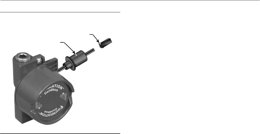
Instruction Manual
D103412X012
Parts
January 2015
227
Figure 8‐1. Terminal Box of Natural Gas Certified
FIELDVUE DVC6200f Digital Valve Controller
GAS‐BLOCKING
PRESS‐FIT ADAPTOR
WIRING CONNECTOR
W9923‐1
Key Description
Module Base
(see figure 8‐2 and 8‐4)
DVC6200f and DVC6205f
2 Module Base(6)
11 Drive Screw(6) (2 req'd)
12 O‐ring(1)
19 Label, Shield Assembly(6)
61 Pipe Plug, hex socket(6) (3 req'd)
243 Slotted Pin (flame arrestor)(6) (3 req'd)
I/P Converter Assembly
(see figure 8‐2 and 8‐4)
DVC6200f and DVC6205f
23 Cap Screw, hex socket, SST(2)(8) (4 req'd)
39* O‐ring(1)(3)(5)
41 I/P Converter(5)
169 Shroud(5)(8) (not shown, see figure 7‐4)
210* Boot, nitrile(1)(5) (2 req'd) (see figure 7‐4)
231* Seal Screen(1)(3)(5)
Key Description Part Number
Relay (see figure 8‐2 and 8‐4)
DVC6200f and DVC6205f
24* Relay Assembly, (includes shroud, relay seal, mounting screws)
Standard (nitrile elastomers)
Standard Bleed
Housing A (used for GX actuator)
Single‐/acting direct (relay C) 38B5786X182
Single‐acting reverse (relay B) 38B5786X172
Housing B (used for all actuators except GX)
Single‐acting direct (relay C) 38B5786X132
Double‐acting (relay A) 38B5786X052
Single‐acting reverse (relay B) 38B5786X092
Low Bleed
Housing A (used for GX actuator)
Single‐acting direct (relay C) 38B5786X202
Single‐acting reverse (relay B) 38B5786X192
Housing B (used for all actuators except G)
Single‐acting direct (relay C) 38B5786X152
Double‐acting (relay A) 38B5786X072
Single‐acting reverse (relay B) 38B5786X112
Extreme Temperature option (fluorosilicone elastomers)
Standard Bleed
Single‐acting direct (relay C) 38B5786X142
Double‐acting (relay A) 38B5786X032
Single‐acting reverse (relay B) 38B5786X102
Low Bleed
Single‐acting direct (relay C) 38B5786X162
Double‐acting (relay A) 38B5786X082
Single‐acting reverse (relay B) 38B5786X122
Loop Connections Terminal Box
(see figure 8‐2 and 8‐4)
DVC6200f and DVC6205f
4 Terminal Box Cap
34* O‐ring(1)(4)
36* O‐ring(1)(4)
58 Set Screw, hex socket, SST(2)
72 Cap Screw, hex socket, SST(2)
164 Terminal Box Assembly
*Recommended spare
1. Available in the Elastomer Spare Parts Kit
2. Available in the Small Hardware Spare Parts Kit
3. Available in the Seal Screen Kit
4. Available in the Terminal Box Kit
5. Available in the I/P Converter Kit
6. Available in the Spare Module Base Assembly Kit
8. Available in the Spare Shroud Kit

Instruction Manual
D103412X012
Parts
January 2015
228
Key Description Part Number
Feedback Connections Terminal
Box (see figure 8‐4)
DVC6205f
4 Terminal Box Cap
34* O‐ring(1)(4)
36* O‐ring(1)(4)
58 Set Screw, hex socket, SST(2)
62 Pipe Plug, hex hd, SST
64 Anti‐seize compound (not furnished with the instrument)
262 Adapter
263* O-ring
Standard 1F463606992
Extreme temperature option, (fluorosilicone) 1F4636X0092
264 Terminal Box Assembly, remote
PWB Assembly
(see figure 8‐2 and 8‐4)
DVC6200f and DVC6205f
Note
Contact your Emerson Process Management sales office if a replacement
PWB is needed.
50* PWB Assembly
Standard Control
Fieldbus Diagnostics
Advanced Diagnostics
Performance DIagnostic
Fieldbus Control
Fieldbus Diagnostics
Advanced Diagnostics
Performance Diagnostics
Fieldbus Logic
Fieldbus Diagnostics
Advanced Diagnostics
Performance Diagnostics
Key Description Part Number
Pressure Gauges, Pipe Plugs, or
Tire Valve Assemblies
(see figure 8‐3)
DVC6200f and DVC6205f
47* Pressure Gauge, nickel‐plated brass case, brass connection
Double‐acting (3 req'd); Single‐acting (2 req'd)
PSI/MPA Gauge Scale
To 60 PSI, 0.4 MPa 18B7713X042
To 160 PSI, 1.1 MPa 18B7713X022
PSI/bar Gauge Scale
To 60 PSI, 4 bar 18B7713X032
To 160 PSI, 11 bar 18B7713X012
PSI/KG/CM2 Gauge Scale
To 60 PSI, 4 KG/CM218B7713X072
To 160 PSI, 11 KG/CM218B7713X082
66 Pipe Plug, hex hd
For double‐acting and single‐acting direct w/gauges
(none req'd)
For single‐acting reverse w/gauges (1 req'd)
For all units w/o gauges (3 req'd)
67 Tire Valve, used with Tire Valve Option only
Double‐acting (3 req'd); Single‐acting (2 req'd)
DVC6215 Feedback Unit
(see figure 8‐5)
65 Lubricant, silicone sealant (not furnished
with the instrument)
256* O-Ring, fluorosilicone 1K1810X0122
*Recommended spare parts
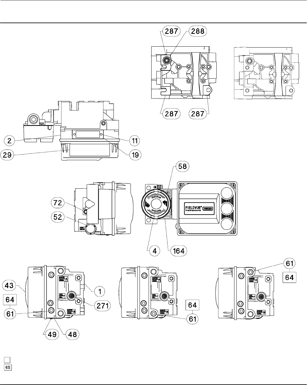
Instruction Manual
D103412X012
Parts
January 2015
229
Figure 8‐2. FIELDVUE DVC6200f Digital Valve Controller
Housing Assembly
DOUBLE‐ACTING DIRECT‐ACTING REVERSE‐ACTING
HOUSING A—BACK VIEW
(USED FOR GX ACTUATOR)
HOUSING B—BACK VIEW
(USED FOR ALL
ACTUATORS EXCEPT GX)
GE40185 sheet 1 of 3
APPLY LUBRICANT, SEALANT, OR THREAD LOCK
APPLY LUBRICANT ON ALL O-RINGS UNLESS OTHERWISE SPECIFIED
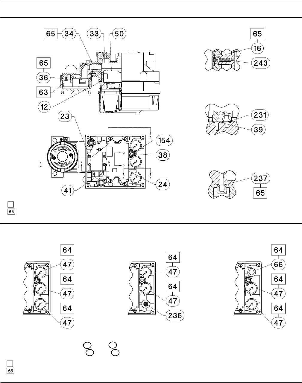
Instruction Manual
D103412X012
Parts
January 2015
230
APPLY LUBRICANT, SEALANT, OR THREAD LOCK
APPLY LUBRICANT ON ALL O-RINGS UNLESS OTHERWISE SPECIFIED
Figure 8‐2. FIELDVUE DVC6200f Digital Valve Controller Housing Assembly (continued)
SECTION A-A
SECTION C-C
SCALE 2 : 1
SECTION E-E
SCALE 2 : 1
SECTION F-F
SCALE 2 : 1
GE40185 sheet 2 of 3
Figure 8‐3. Gauge Configuration
DOUBLE‐ACTING DIRECT‐ACTING REVERSE‐ACTING
GE40185 sheet 3 of 3
FOR PIPE PLUG OPTION REPLACE 47 WITH 66
FOR TIRE VALVE OPTION REPLACE 47 WITH 67
APPLY LUBRICANT, SEALANT, OR THREAD LOCK
APPLY LUBRICANT ON ALL O-RINGS UNLESS OTHERWISE SPECIFIED
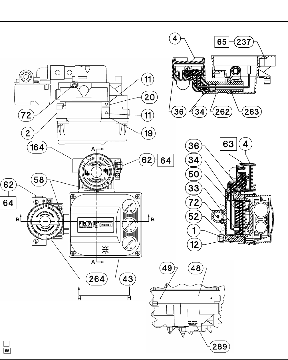
Instruction Manual
D103412X012
Parts
January 2015
231
Figure 8‐4. FIELDVUE DVC6205f Base Unit Housing Assembly
SECTION B-B
SECTION H-H
SECTION A-A
GE40181
APPLY LUBRICANT, SEALANT, OR THREAD LOCK
APPLY LUBRICANT ON ALL O-RINGS UNLESS OTHERWISE SPECIFIED
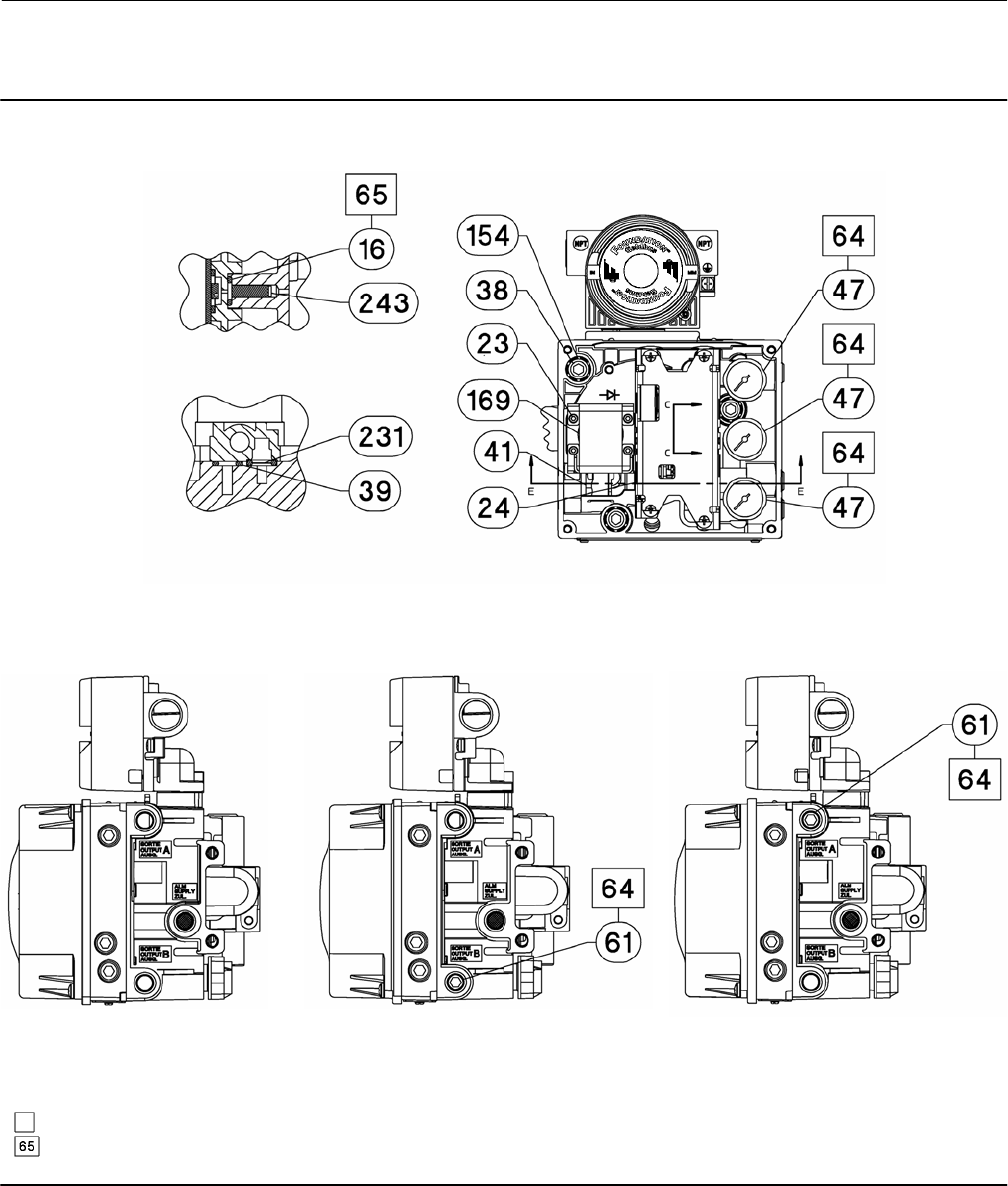
Instruction Manual
D103412X012
Parts
January 2015
232
Figure 8‐4. FIELDVUE DVC6205f Base Unit Housing Assembly (continued)
SECTION C-C
SCALE 2 : 1
SECTION E-E
SCALE 2 : 1
DOUBLE‐ACTING DIRECT‐ACTING REVERSE‐ACTING
DOUBLE‐ACTING SHOWN
GE40181
APPLY LUBRICANT, SEALANT, OR THREAD LOCK
APPLY LUBRICANT ON ALL O-RINGS UNLESS OTHERWISE SPECIFIED
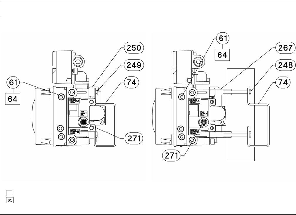
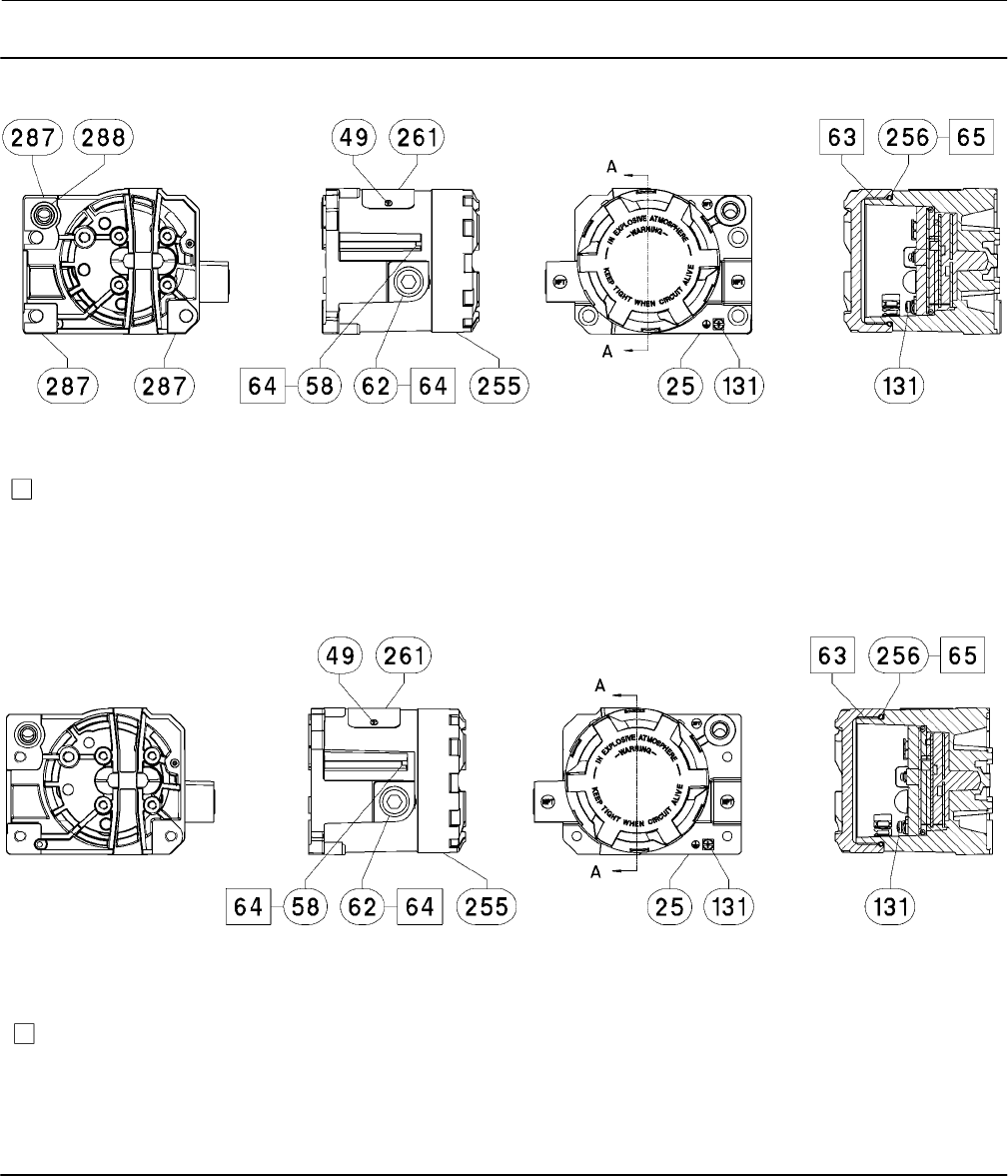
Instruction Manual
D103412X012
Parts
January 2015
234
Figure 8‐5. FIELDVUE DVC6215 Remote Feedback Assembly
SECTION A-A
HOUSING A
(USED FOR GX ACTUATOR)
HOUSING B
(USED FOR ALL ACTUATORS EXCEPT GX)
SECTION A-A
PARTS NOT SHOWN: 158
PARTS NOT SHOWN: 158
GE46670-B
GE40178-B
APPLY LUBRICANT/SEALANT
APPLY LUBRICANT/SEALANT
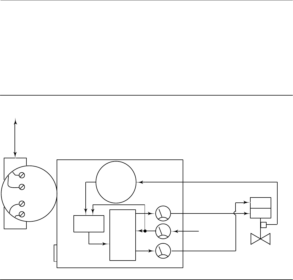
Instruction Manual
D103412X012
Principle of Operation
January 2015
235
Appendix A Principle of OperationA‐A‐
Digital Valve Controller Operation
The DVC6200f digital valve controller has a single module base that may be easily replaced in the field without
disconnecting field wiring or tubing. The master module contains the following submodules: current‐to‐pneumatic
(I/P) converter, printed wiring board assembly, and pneumatic relay. The relay position is detected by sensing the
magnet on the relay beam via a detector on the printed wiring board. This sensor is used for the minor loop feedback
(MLFB) reading. The master module can be rebuilt by replacing the submodules. See figures A‐1 and A‐2.
Figure A‐1. FIELDVUE DVC6200f Digital Valve Controller Block Diagram
E1376
DIGITAL
SETPOINT
9–32 VOLT
FIELDBUS
SUPPLY
PRESSURE
PRINTED
WIRING BOARD
PNEUMATIC
RELAY
I/P
CONVERTER
OUTPUT A
OUTPUT B
VALVE TRAVEL FEEDBACK
AUXILIARY
TERMINALS
TERMINAL BOX
DRIVE
SIGNAL
VALVE AND
ACTUATOR
VENT
The DVC6200f digital valve controller is a bus‐powered instrument that provides a control valve position in response
to a digital setpoint from the control room. The following describes a direct acting DVC6200f digital valve controller
mounted on a sliding-stem piston actuator, where the valve is closed with zero power to the instrument.
The setpoint is routed into the terminal box through a single pair of wires and then to the printed wiring board
assembly submodule where it is read by the microprocessor, processed by a digital algorithm, and converted into an
analog I/P drive signal.
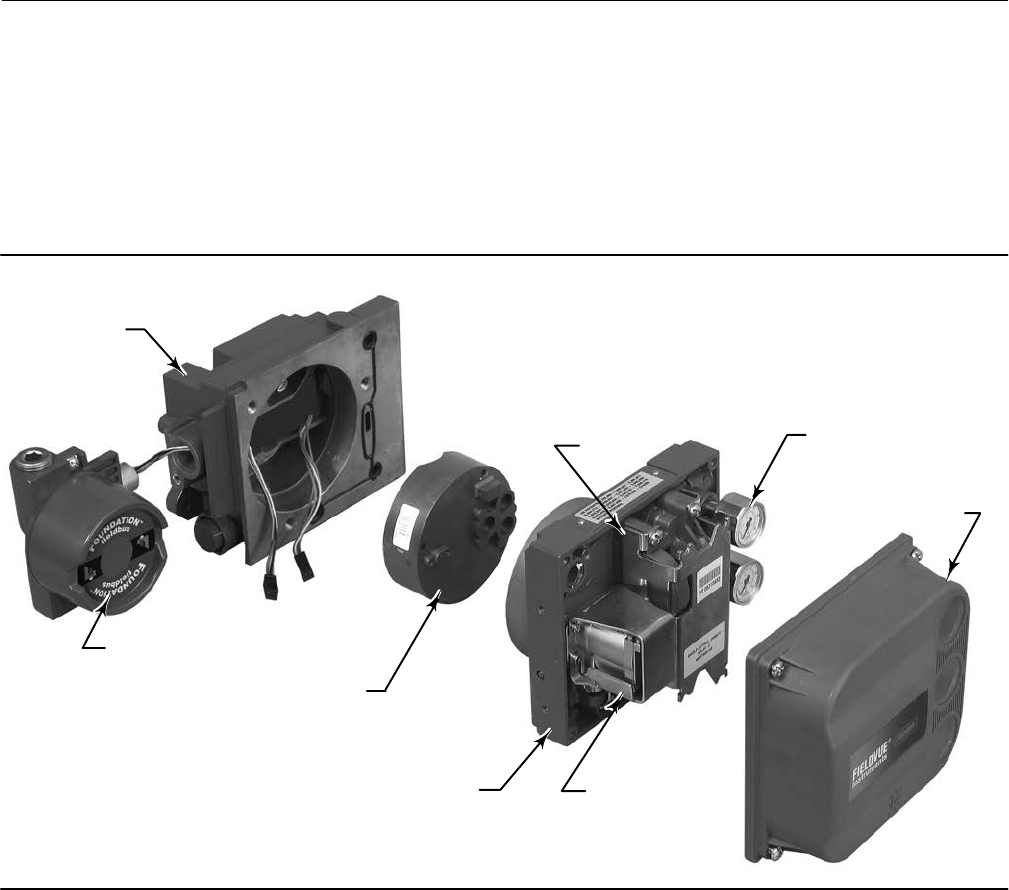
Instruction Manual
D103412X012
Principle of Operation
January 2015
236
As the setpoint increases, the drive signal to the I/P converter increases, increasing the I/P output pressure. The I/P
output pressure is routed to the pneumatic relay submodule. The relay is also connected to supply pressure and
amplifies the small pneumatic signal from the I/P converter. The relay accepts the amplified pneumatic signal and
provides two output pressures. With relay A, an increasing setpoint will produce increasing pressure at output A and
decreasing pressure at output B. With relay B an increasing setpoint will produce decreasing pressure at output B
(output A is not available). With relay C an increasing setpoint will produce an increasing pressure on output A (output
B is not available). The output A pressure is used for double‐acting and single‐acting direct applications. The output B
pressure is used for double‐acting and single‐acting reverse applications.
TERMINAL BOX
WITH COVER
MODULE BASE ASSEMBLY
PRINTED WIRING
BOARD ASSEMBLY
I/P CONVERTER
PNEUMATIC
RELAY
HOUSING
GAUGES
COVER
W9925‐1
Figure A‐2. FIELDVUE DVC6200f Digital Valve Controller Assembly
As shown in figure A‐1, the increased output A pressure causes the actuator stem to move upward. The stem position
is sensed by the travel sensor. The stem continues to move upward until the correct stem position is attained. At this
point the printed wiring board assembly stabilizes the I/P drive signal. This prevents any further increase in the
pneumatic signal from the I/P converter.
As the digital setpoint decreases, the drive signal to the I/P converter submodule decreases, decreasing the I/P output
pressure. The pneumatic relay decreases the output A pressure and increases the output B pressure. The stem moves
downward until the correct position is attained. At this point the printed wiring board assembly stabilizes the I/P drive
signal. This prevents any decrease in the pneumatic signal from the I/P converter.

Instruction Manual
D103412X012
Field Communicator Menu Structure
January 2015
237
Appendix B Field Communicator Menu StructureB‐B‐
This section contains the Field Communicator menu trees for the transducer block and the resource block. It also
contains Fast Key Sequence tables with coordinates to help locate the function/variable on the appropriate menu tree.

Instruction Manual
D103412X012
Field Communicator Menu Structure
January 2015
238
Transducer Block (TB) Menu Structure
Parameter Label Menu Structure
A Minus B TB > Device Variables > Pressures > A Minus B
Actual Travel TB > Configure/Setup > Detailed Setup > Valve and Actuator > Valve > Actual Travel
Actuator Fail Action TB > Configure/Setup > Detailed Setup > Valve and Actuator > Actuator > Actuator Fail Action
Actuator Manufacturer TB > Configure/Setup > Detailed Setup > Valve and Actuator > Actuator > Actuator Manufacturer
Actuator Model Number TB > Configure/Setup > Detailed Setup > Valve and Actuator > Actuator > Actuator Model Number
Actuator Serial Number TB > Configure/Setup > Detailed Setup > Valve and Actuator > Actuator > Actuator Serial Number
Actuator Size TB > Configure/Setup > Detailed Setup > Valve and Actuator > Actuator > Actuator Size
Actuator Style TB > Configure/Setup > Detailed Setup > Valve and Actuator > Actuator > Actuator Style
Advise Active TB > Configure/Setup > Detailed Setup > Alert Handling > Simulate Active Alerts > Advise Active
Advise Enable TB > Configure/Setup > Detailed Setup > Alerts > PlantWeb Alert Enable > Advise Enable
Advise Suppress TB > Configure/Setup > Detailed Setup > Alerts > PlantWeb Alert Reporting > Advise Suppress
Air TB > Configure/Setup > Detailed Setup > Valve and Actuator > Actuator > Air
Alert Conditions TB > Device Diagnostics > Alert Conditions
Alert Key TB > Configure/Setup > Detailed Setup > Alerts > Configuration Alerts > Alert Key
Area Units TB > Configure/Setup > Detailed Setup > Instrument > Area Units
Block Configuration Error TB > Device Diagnostics > Status > Block Error > Block Configuration Error
Blocks Set to Defaults Alert TB > Configure/Setup > Detailed Setup > Alerts > Configuration Alerts > Blocks Set to Defaults > Block Set to Defaults Alert
Blocks Set to Defaults Alert
Enable TB > Configure/Setup > Detailed Setup > Alerts > Configuration Alerts > Blocks Set to Defaults > Block Set to Defaults Alert Enable
Calibration Date TB > Configure/Setup > Detailed Setup > Instrument > Calibration Date
Calibration Location TB > Configure/Setup > Detailed Setup > Instrument > Calibration Location
Calibration Person TB > Configure/Setup > Detailed Setup > Instrument > Calibration Person
Custom Characterization Table TB > Configure/Setup > Detailed Setup > Response Control > Custom Characterization Table
Cycle Counter TB > Configure/Setup > Detailed Setup > Alerts > Travel History Alerts > Cycle Counter > Cycle Counter
TB > Device Variables > Cycle Counter
Cycle Counter Alert TB > Configure/Setup > Detailed Setup > Alerts > Travel History Alerts > Cycle Counter > Cycle Counter Alert
Cycle Counter Alert Enable TB > Configure/Setup > Detailed Setup > Alerts > Travel History Alerts > Cycle Counter > Cycle Counter Alert Enable
Cycle Counter Alert Point TB > Configure/Setup > Detailed Setup > Alerts > Travel History Alerts > Cycle Counter > Cycle Counter Alert Point
Cycle Counter Deadband TB > Configure/Setup > Detailed Setup > Alerts > Travel History Alerts > Cycle Counter > Cycle Counter Deadband
Device Needs Maintenance Now TB > Device Diagnostics > Status > Block Error > Device Needs Maintenance Now
Drive Current TB > Configure/Setup > Detailed Setup > Alerts > Elect Alerts > Drive Current > Drive Current
Drive Current Alert TB > Device Diagnostics > Status > Self Test Status > Drive Current Alert
TB > Configure/Setup > Detailed Setup > Alerts > Elect Alerts > Drive Current > Drive Current Alert
Drive Current Alert Enable TB > Configure/Setup > Detailed Setup > Alerts > Elect Alerts > Drive Current > Drive Current Alert Enable
Drive Current Alert Point TB > Configure/Setup > Detailed Setup > Alerts > Elect Alerts > Drive Current > Drive Current Alert Point
Drive Current Alert Time TB > Configure/Setup > Detailed Setup > Alerts > Elect Alerts > Drive Current > Drive Current Alert Time
Drive Current Manual Recovery TB > Configure/Setup > Detailed Setup > Alerts > Elect Alerts > Drive Current > Drive Current Manual Recovery
Drive Current Shutdown TB > Configure/Setup > Detailed Setup > Alerts > Elect Alerts > Drive Current > Drive Current Shutdown
Drive Signal TB > Configure/Setup > Detailed Setup > Alerts > Elect Alerts > Drive Signal > Drive Signal
TB > Device Variables > Drive Signal
Drive Signal Alert TB > Configure/Setup > Detailed Setup > Alerts > Elect Alerts > Drive Signal > Drive Signal Alert
Drive Signal Alert Enable TB > Configure/Setup > Detailed Setup > Alerts > Elect Alerts > Drive Signal > Drive Signal Alert Enable
Effective Area TB > Configure/Setup > Detailed Setup > Valve and Actuator > Actuator > Effective Area
Failed Active TB > Configure/Setup > Detailed Setup > Alert Handling > Simulate Active Alerts > Failed Active
Failed Enable TB > Configure/Setup > Detailed Setup > Alerts > PlantWeb Alert Enable > Failed Enable
Failed Suppress TB > Configure/Setup > Detailed Setup > Alerts > PlantWeb Alert Reporting > Failed Suppress
Feedback Connection TB > Configure/Setup > Detailed Setup > Valve and Actuator > Actuator > Feedback Connection
Flow Direction TB > Configure/Setup > Detailed Setup > Valve and Actuator > Trim > Flow Direction
Flow Tends To TB > Configure/Setup > Detailed Setup > Valve and Actuator > Trim > Flow Tends To
I/O Processor Alert TB > Configure/Setup > Detailed Setup > Alerts > Elect Alerts > Processor Impaired > I/O Processor Alert
I/O Processor Alert Enable TB > Configure/Setup > Detailed Setup > Alerts > Elect Alerts > Processor Impaired > I/O Processor Alert Enable
I/O Processor Man Recovery TB > Configure/Setup > Detailed Setup > Alerts > Elect Alerts > Processor Impaired > I/O Processor Man Recovery
I/O Processor Shutdown TB > Configure/Setup > Detailed Setup > Alerts > Elect Alerts > Processor Impaired > I/O Processor Shutdown
Inlet Pressure TB > Configure/Setup > Detailed Setup > Valve and Actuator > Valve > Inlet Pressure
−Continued−

Instruction Manual
D103412X012
Field Communicator Menu Structure
January 2015
239
Transducer Block (TB) Menu Structure (Continued)
Menu StructureParameter Label
Input Characterization TB > Configure/Setup > Detailed Setup > Response Control > Input Characterization
TB > Device Variables > Input Characterization
Integrator Limited Hi TB > Device Diagnostics > Status > Self Test Status > Integrator Limited Hi
Integrator Limited Lo TB > Device Diagnostics > Status > Self Test Status > Integrator Limited Lo
Integrator Suspended TB > Device Diagnostics > Status > Self Test Status > Integrator Suspended
IOP Failure TB > Device Diagnostics > Status > Self Test Status > IOP Failure
Last Calibration Type TB > Configure/Setup > Detailed Setup > Instrument > Last Calibration Type
Leak Class TB > Configure/Setup > Detailed Setup > Valve and Actuator > Trim > Leak Class
Length Units TB > Configure/Setup > Detailed Setup > Instrument > Length Units
Lever Arm Length TB > Configure/Setup > Detailed Setup > Valve and Actuator > Actuator > Lever Arm Length
Lever Style TB > Configure/Setup > Detailed Setup > Valve and Actuator > Actuator > Lever Style
Lost Static Data TB > Device Diagnostics > Status > Block Error > Lost Static Data
Lower Bench Set TB > Configure/Setup > Detailed Setup > Valve and Actuator > Actuator > Lower Bench Set
MAI Channel 1 TB > Configure/Setup > Detailed Setup > MAI Channel Map > MAI Channel 1
MAI Channel 2 TB > Configure/Setup > Detailed Setup > MAI Channel Map > MAI Channel 2
MAI Channel 3 TB > Configure/Setup > Detailed Setup > MAI Channel Map > MAI Channel 3
MAI Channel 4 TB > Configure/Setup > Detailed Setup > MAI Channel Map > MAI Channel 4
MAI Channel 5 TB > Configure/Setup > Detailed Setup > MAI Channel Map > MAI Channel 5
MAI Channel 6 TB > Configure/Setup > Detailed Setup > MAI Channel Map > MAI Channel 6
MAI Channel 7 TB > Configure/Setup > Detailed Setup > MAI Channel Map > MAI Channel 7
MAI Channel 8 TB > Configure/Setup > Detailed Setup > MAI Channel Map > MAI Channel 8
Maint Active TB > Configure/Setup > Detailed Setup > Alert Handling > Simulate Active Alerts > Maint Active
Maintenance Enable TB > Configure/Setup > Detailed Setup > Alerts > PlantWeb Alert Enable > Maintenance Enable
Maintenance Suppress TB > Configure/Setup > Detailed Setup > Alerts > PlantWeb Alert Reporting > Maintenance Suppress
Maximum Recorded Supply
Pressure TB > Device Diagnostics > Device Record > Maximum Recorded Supply Pressure
Maximum Recorded Supply
Pressure Time TB > Device Diagnostics > Device Record > Maximum Recorded Supply Pressure Time
Maximum Recorded
Temperature TB > Device Diagnostics > Device Record > Maximum Recorded Temperature
Maximum Recorded
Temperature Time TB > Device Diagnostics > Device Record > Maximum Recorded Temperature Time
Maximum Supply Pressure TB > Configure/Setup > Detailed Setup > Instrument > Maximum Supply Pressure
Minimum Recorded Supply
Pressure TB > Device Diagnostics > Device Record > Minimum Recorded Supply Pressure
Minimum Recorded Supply
Pressure Time TB > Device Diagnostics > Device Record > Minimum Recorded Supply Pressure Time
Minimum Recorded
Temperature TB > Device Diagnostics > Device Record > Minimum Recorded Temperature
Minimum Recorded
Temperature Time TB > Device Diagnostics > Device Record > Minimum Recorded Temperature Time
MLFB Error TB > Device Diagnostics > Status > Self Test Status > MLFB Error
Nominal Supply Pressure TB > Configure/Setup > Detailed Setup > Valve and Actuator > Actuator > Nominal Supply Pressure
Out of Service TB > Device Diagnostics > Status > Block Error > Out of Service
Outlet Pressure TB > Configure/Setup > Detailed Setup > Valve and Actuator > Valve > Outlet Pressure
Outblock Selection TB > Configure/Setup > Detailed Setup > Response Control > Outblock Selection
Output Block Timeout TB > Configure/Setup > Detailed Setup > Alerts > Configuration Alerts > Output Block Timeout
Output Block Timeout Alert TB > Configure/Setup > Detailed Setup > Alerts > Configuration Alerts > Output Block Timeout > Output Block Timeout Alert
Output Block Timeout Alert
Enable TB > Configure/Setup > Detailed Setup > Alerts > Configuration Alerts > Output Block Timeout > Output Block Timeout Alert Enable
Output Block Timeout Manual
Recovery
TB > Configure/Setup > Detailed Setup > Alerts > Configuration Alerts > Output Block Timeout > Output Block Timeout Manual
Recovery
Output Block Timeout Shutdown TB > Configure/Setup > Detailed Setup > Alerts > Configuration Alerts > Output Block Timeout > Output Block Timeout Shutdown
Packing Type TB > Configure/Setup > Detailed Setup > Valve and Actuator > Valve > Packing Type
PD Inside Status TB > Configure/Setup > Device Variables > PD Inside Status
PD Run TB > Configure/Setup > Detailed Setup > Alerts > Performance Alerts > PD Run
−Continued−

Instruction Manual
D103412X012
Field Communicator Menu Structure
January 2015
240
Transducer Block (TB) Menu Structure (Continued)
Menu StructureParameter Label
Performance Critical Alert TB > Configure/Setup > Detailed Setup > Alerts > Performance Alerts > Performance Critical Alert
Performance Critical Alert Enable TB > Configure/Setup > Detailed Setup > Alerts > Performance Alerts > Performance Critical Alert Enable
Performance Information Alert TB > Configure/Setup > Detailed Setup > Alerts > Performance Alerts > Peformance Information Alert
Performance Information Alert
Enable TB > Configure/Setup > Detailed Setup > Alerts > Performance Alerts > Peformance Information Alert Enable
Performance Reduced Alert TB > Configure/Setup > Detailed Setup > Alerts > Performance Alerts > Peformance Reduced Alert
Performance Reduced Alert
Enable TB > Configure/Setup > Detailed Setup > Alerts > Performance Alerts > Peformance Reduced Alert Enable
Performance Tuner TB > Configure/Setup > Basic Setup > Performance Tuner
TB > Configure/Setup > Detailed Setup > Response Control > Travel Tuning > Performance Tuner
PlantWeb Alert Simulate TB > Configure/Setup > Detailed Setup > Alert Handling > PlantWeb Alert Simulate
Port Diameter TB > Configure/Setup > Detailed Setup > Valve and Actuator > Trim > Port Diameter
Port Type TB > Configure/Setup > Detailed Setup > Valve and Actuator > Trim > Port Type
Pressure A TB > Device Variables > Pressures > Pressure A
Pressure A Sensor Alert TB > Configure/Setup > Detailed Setup > Alerts > Sensor Alerts > Pressure Sensors > Pressure A Sensor Alert
Pressure A Sensor Alert Enable TB > Configure/Setup > Detailed Setup > Alerts > Sensor Alerts > Pressure Sensors > Pressure A Sensor Alert Enable
Pressure A Sensor Failure TB > Device Diagnostics > Status > Self Test Status > Pressure A Sensor Error
Pressure A Sensor Manual
Recovery TB > Configure/Setup > Detailed Setup > Alerts > Sensor Alerts > Pressure Sensors > Pressure A Sensor Manual Recovery
Pressure A Sensor Shutdown TB > Configure/Setup > Detailed Setup > Alerts > Sensor Alerts > Pressure Sensors > Pressure A Sensor Shutdown
Pressure B TB > Device Variables > Pressures > Pressure B
Pressure B Sensor Alert TB > Configure/Setup > Detailed Setup > Alerts > Sensor Alerts > Pressure Sensors > Pressure B Sensor Alert
Pressure B Sensor Alert Enable TB > Configure/Setup > Detailed Setup > Alerts > Sensor Alerts > Pressure Sensors > Pressure B Sensor Alert Enable
Pressure B Sensor Failure TB > Device Diagnostics > Status > Self Test Status > Pressure B Sensor Error
Pressure Cutoff Closed TB > Configure/Setup > Detailed Setup > Response Control > Travel Pressure Control > Pressure Cutoff Closed
Pressure Cutoff Open TB > Configure/Setup > Detailed Setup > Response Control > Travel Pressure Control > Pressure Cutoff Open
Pressure Fallback Alert TB > Configure/Setup > Detailed Setup > Alerts > Sensor Alerts > Pressure Fallback > Pressure Fallback Alert
Pressure Fallback Alert Enable TB > Configure/Setup > Detailed Setup > Alerts > Sensor Alerts > Pressure Fallback > Pressure Fallback Alert Enable
Pressure Integral Dead Zone TB > Configure/Setup > Detailed Setup > Response Control > Pressure Tuning > Pressure Integral Dead Zone
Pressure Integral Gain TB > Configure/Setup > Detailed Setup > Response Control > Pressure Tuning > Pressure Integral Gain
Pressure Integral Limit Hi TB > Configure/Setup > Detailed Setup > Response Control > Pressure Tuning > Pressure Integral Limit Hi
Pressure Integral Limit Lo TB > Configure/Setup > Detailed Setup > Response Control > Pressure Tuning > Pressure Integral Limit Lo
Pressure MLFB Gain TB > Configure/Setup > Detailed Setup > Response Control > Pressure Tuning > Pressure MLFB Gain
Pressure Proportional Gain TB > Configure/Setup > Detailed Setup > Response Control > Pressure Tuning > Pressure Proportional Gain
Pressure Range Hi TB > Configure/Setup > Detailed Setup > Response Control > Travel Pressure Control > Pressure Range Hi
Pressure Range Lo TB > Configure/Setup > Detailed Setup > Response Control > Travel Pressure Control > Pressure Range Lo
Pressure Tuning Set TB > Configure/Setup > Detailed Setup > Response Control > Pressure Tuning > Pressure Tuning Set
Pressure Units TB > Configure/Setup > Detailed Setup > Instrument > Pressure Units
Processor Alert TB > Configure/Setup > Detailed Setup > Alerts > Elect Alerts > Processor Impaired > Processor Alert
Processor Alert Enable TB > Configure/Setup > Detailed Setup > Alerts > Elect Alerts > Processor Impaired > Processor Alert Enable
Program Memory Alert TB > Configure/Setup > Detailed Setup > Alerts > Elect Alerts > Processor Impaired > Program Memory Alert
Program Memory Alert Enable TB > Configure/Setup > Detailed Setup > Alerts > Elect Alerts > Processor Impaired > Program Memory Alert Enable
Program Memory Manual
Recovery TB > Configure/Setup > Detailed Setup > Alerts > Elect Alerts > Processor Impaired > Program Memory Manual Recovery
Program Memory Shutdown TB > Configure/Setup > Detailed Setup > Alerts > Elect Alerts > Processor Impaired > Program Memory Shutdown
Protection TB > Device Variables > Protection
Proximity Hi Alert TB > Configure/Setup > Detailed Setup > Alerts > Prox Alerts > Proximity > Proximity Hi Alert
Proximity Hi Alert Enable TB > Configure/Setup > Detailed Setup > Alerts > Prox Alerts > Proximity > Proximity Hi Alert Enable
Proximity Hi Hi Alert TB > Configure/Setup > Detailed Setup > Alerts > Prox Alerts > Proximity > Proximity Hi Hi Alert
Proximity Hi Hi Alert Enable TB > Configure/Setup > Detailed Setup > Alerts > Prox Alerts > Proximity > Proximity Hi Hi Alert Enable
Proximity Lo Alert TB > Configure/Setup > Detailed Setup > Alerts > Prox Alerts > Proximity > Proximity Lo Alert
Proximity Lo Alert Enable TB > Configure/Setup > Detailed Setup > Alerts > Prox Alerts > Proximity > Proximity Lo Alert Enable
Proximity Lo Lo Alert TB > Configure/Setup > Detailed Setup > Alerts > Prox Alerts > Proximity > Proximity Lo Lo Alert
Proximity Lo Lo Alert Enable TB > Configure/Setup > Detailed Setup > Alerts > Prox Alerts > Proximity > Proximity Lo Lo Alert Enable
Push Down To TB > Configure/Setup > Detailed Setup > Valve and Actuator > Trim > Push Down To
−Continued−

Instruction Manual
D103412X012
Field Communicator Menu Structure
January 2015
241
Transducer Block (TB) Menu Structure (Continued)
Menu StructureParameter Label
Rated Travel TB > Configure/Setup > Detailed Setup > Valve and Actuator > Valve > Rated Travel
Relay Type TB > Configure/Setup > Detailed Setup > Instrument > Relay Type
Seat Type TB > Configure/Setup > Detailed Setup > Valve and Actuator > Trim > Seat Type
Setpoint TB > Device Variables > AO Control‐Pre‐Char > Setpoint
Setpoint Status TB > Device Variables > AO Control‐Pre‐Char > Setpoint Status
Setpoint(D) TB > Device Variables > DO Control > Setpoint(D)
Shaft Stem Diameter TB > Configure/Setup > Detailed Setup > Valve and Actuator > Valve > Shaft Stem Diameter
Simulate Active TB > Device Diagnostics > Status > Block Error > Simulate Active
Simulate Jumper ON TB > Device Diagnostics > Status > Self Test Status > Simulate Jumper ON
Spring Rate TB > Configure/Setup > Detailed Setup > Valve and Actuator > Actuator > Spring Rate
Spring Rate Units TB > Configure/Setup > Detailed Setup > Instrument > Spring Rate Units
Static Memory Alert TB > Configure/Setup > Detailed Setup > Alerts > Elect Alerts > Processor Impaired > Static Memory Alert
Static Memory Alert Enable TB > Configure/Setup > Detailed Setup > Alerts > Elect Alerts > Processor Impaired > Static Memory Alert Enable
Static Memory Manual Recovery TB > Configure/Setup > Detailed Setup > Alerts > Elect Alerts > Processor Impaired > Static Memory Manual Recovery
Static Memory Shutdown TB > Configure/Setup > Detailed Setup > Alerts > Elect Alerts > Processor Impaired > Static Memory Shutdown
Stroke Time Close TB > Configure/Setup > Detailed Setup > Valve and Actuator > Reference > Stroke Time Close
Stroke Time Open TB > Configure/Setup > Detailed Setup > Valve and Actuator > Reference > Stroke Time Open
Supply TB > Configure/Setup > Detailed Setup > Alerts > Environment Alerts > Supply Pressure > Supply
TB > Device Variables > Pressures > Supply
Supply Pressure Hi Alert TB > Configure/Setup > Detailed Setup > Alerts > Environment Alerts > Supply Pressure > Supply Pressure Hi Alert
Supply Pressure Hi Alert Enable TB > Configure/Setup > Detailed Setup > Alerts > Environment Alerts > Supply Pressure > Supply Pressure Hi Alert Enable
Supply Pressure Hi Alert Point TB > Configure/Setup > Detailed Setup > Alerts > Environment Alerts > Supply Pressure > Supply Pressure Hi Alert Point
Supply Pressure Lo Alert TB > Configure/Setup > Detailed Setup > Alerts > Environment Alerts > Supply Pressure > Supply Pressure Lo Alert
Supply Pressure Lo Alert Enable TB > Configure/Setup > Detailed Setup > Alerts > Environment Alerts > Supply Pressure > Supply Pressure Lo Alert Enable
Supply Pressure Lo Alert Point TB > Configure/Setup > Detailed Setup > Alerts > Environment Alerts > Supply Pressure > Supply Pressure Lo Alert Point
Supply Pressure Sensor Alert TB > Configure/Setup > Detailed Setup > Alerts > Sensor Alerts > Pressure Sensors > Supply Pressure Sensor Alert
Supply Pressure Sensor Alert
Enable TB > Configure/Setup > Detailed Setup > Alerts > Sensor Alerts > Pressure Sensors > Supply Pressure Sensor Alert Enable
Supply Sensor Failure TB > Device Diagnostics > Status > Self Test Status > Supply Sensor Failure
Tag Description TB > Configure/Setup > Detailed Setup > Instrument > Tag Description
Temperature TB > Configure/Setup > Detailed Setup > Alerts > Environment Alerts > Temperature Limit > Temperature
Temperature Hi Alert TB > Configure/Setup > Detailed Setup > Alerts > Environment Alerts > Temperature Limit > Temperature Hi Alert
Temperature Hi Alert Enable TB > Configure/Setup > Detailed Setup > Alerts > Environment Alerts > Temperature Limit > Temperature Hi Alert Enable
Temperature Hi Alert Point TB > Configure/Setup > Detailed Setup > Alerts > Environment Alerts > Temperature Limit > Temperature Hi Alert Point
Temperature Lo Alert TB > Configure/Setup > Detailed Setup > Alerts > Environment Alerts > Temperature Limit > Temperature Lo Alert
Temperature Lo Alert Enable TB > Configure/Setup > Detailed Setup > Alerts > Environment Alerts > Temperature Limit > Temperature Lo Alert Enable
Temperature Lo Alert Point TB > Configure/Setup > Detailed Setup > Alerts > Environment Alerts > Temperature Limit > Temperature Lo Alert Point
Temperature Sensor Alert TB > Configure/Setup > Detailed Setup > Alerts > Sensor Alerts > Temperature Sensor > Temperature Sensor Alert
Temperature Sensor Alert Enable TB > Configure/Setup > Detailed Setup > Alerts > Sensor Alerts > Temperature Sensors > Temperature Sensor Alert Enable
Temperature Units TB > Configure/Setup > Detailed Setup > Instrument > Temperature Units
Travel TB > Configure/Setup > Detailed Setup > Alerts > Prox Alerts > Travel
Travel (DeChar) TB > Device Variables > AO Control‐Pre‐Char > Travel(DeChar)
Travel Accumulator TB > Configure/Setup > Detailed Setup > Alerts > Travel History Alerts > Travel Accumulator > Travel Accumulator
TB > Device Variables > Travel Accumulator
Travel Accumulator Alert TB > Configure/Setup > Detailed Setup > Alerts > Travel History Alerts > Travel Accumulator > Travel Accumulator Alert
Travel Accumulator Alert Enable TB > Configure/Setup > Detailed Setup > Alerts > Travel History Alerts > Travel Accumulator > Travel Accumulator Alert Enable
Travel Accumulator Alert Point TB > Configure/Setup > Detailed Setup > Alerts > Travel History Alerts > Travel Accumulator > Travel Accumulator Alert Point
Travel Accumulator Deadband TB > Configure/Setup > Detailed Setup > Alerts > Travel History Alerts > Travel Accumulator > Travel Accumulator Deadband
Travel Closed Alert TB > Configure/Setup > Detailed Setup > Alerts > Prox Alerts > Travel Closed > Travel Closed Alert
Travel Closed Alert Enable TB > Configure/Setup > Detailed Setup > Alerts > Prox Alerts > Travel Closed > Travel Closed Alert Enable
Travel Closed Alert Point TB > Configure/Setup > Detailed Setup > Alerts > Prox Alerts > Travel Closed > Travel Closed Alert Point
Travel Closed Deadband TB > Configure/Setup > Detailed Setup > Alerts > Prox Alerts > Travel Closed > Travel Closed Deadband
Travel Count TB > Device Variables > Travel Count
Travel Cutoff Hi TB > Configure/Setup > Detailed Setup > Response Control > Travel Pressure Control > Travel Cutoff Hi
−Continued−

Instruction Manual
D103412X012
Field Communicator Menu Structure
January 2015
242
Transducer Block (TB) Menu Structure (Continued)
Menu StructureParameter Label
Travel Cutoff Lo TB > Configure/Setup > Detailed Setup > Response Control > Travel Pressure Control > Travel Cutoff Lo
Travel Deviation TB > Configure/Setup > Detailed Setup > Alerts > Travel Alerts > Travel Deviation > Travel Deviation
Travel Deviation Alert TB > Configure/Setup > Detailed Setup > Alerts > Travel Alerts > Travel Deviation > Travel Deviation Alert
Travel Deviation Alert Enable TB > Configure/Setup > Detailed Setup > Alerts > Travel Alerts > Travel Deviation > Travel Deviation Alert Enable
Travel Deviation Alert Point TB > Configure/Setup > Detailed Setup > Alerts > Travel Alerts > Travel Deviation > Travel Deviation Alert Point
Travel Deviation Deadband TB > Configure/Setup > Detailed Setup > Alerts > Travel Alerts > Travel Deviation > Travel Deviation Deadband
Travel Deviation Pressure
Fallback TB > Configure/Setup > Detailed Setup > Response Control > Travel Pressure Control > Travel Deviation Pressure Fallback
Travel Deviation Time TB > Configure/Setup > Detailed Setup > Alerts > Travel Alerts > Travel Deviation > Travel Deviation Time
Travel Hi Alert TB > Configure/Setup > Detailed Setup > Alerts > Travel Alerts > Travel Hi/Lo > Travel Hi Alert
Travel Hi Alert Enable TB > Configure/Setup > Detailed Setup > Alerts > Travel Alerts > Travel Hi/Lo > Travel Hi Alert Enable
Travel Hi Alert Point TB > Configure/Setup > Detailed Setup > Alerts > Travel Alerts > Travel Hi/Lo > Travel Hi Alert Point
Travel Hi Deadband TB > Configure/Setup > Detailed Setup > Alerts > Travel Alerts > Travel Hi/Lo > Travel Hi Deadband
Travel Hi Hi Alert TB > Configure/Setup > Detailed Setup > Alerts > Travel Alerts > Travel Limit > Travel Hi Hi Alert
Travel Hi Hi Alert Enable TB > Configure/Setup > Detailed Setup > Alerts > Travel Alerts > Travel Limit > Travel Hi Hi Alert Enable
Travel Hi Hi Alert Point TB > Configure/Setup > Detailed Setup > Alerts > Travel Alerts > Travel Limit > Travel Hi Hi Alert Point
Travel Hi Hi Deadband TB > Configure/Setup > Detailed Setup > Alerts > Travel Alerts > Travel Limit > Travel Hi Hi Deadband
Travel Integral Dead Zone TB > Configure/Setup > Detailed Setup > Response Control > Travel Tuning > Travel Integral Dead Zone
Travel Integral Enable TB > Configure/Setup > Detailed Setup > Response Control > Travel Tuning > Travel Integral Enable
Travel Integral Gain TB > Configure/Setup > Detailed Setup > Response Control > Travel Tuning > Travel Integral Gain
Travel Integral Limit Hi TB > Configure/Setup > Detailed Setup > Response Control > Travel Tuning > Travel Integral Limit Hi
Travel Integral Limit Lo TB > Configure/Setup > Detailed Setup > Response Control > Travel Tuning > Travel Integral Limit Lo
Travel Lo Alert TB > Configure/Setup > Detailed Setup > Alerts > Travel Alerts > Travel Hi/Lo > Travel Lo Alert
Travel Lo Alert Enable TB > Configure/Setup > Detailed Setup > Alerts > Travel Alerts > Travel Hi/Lo > Travel Lo Alert Enable
Travel Lo Alert Point TB > Configure/Setup > Detailed Setup > Alerts > Travel Alerts > Travel Hi/Lo > Travel Lo Alert Point
Travel Lo Deadband TB > Configure/Setup > Detailed Setup > Alerts > Travel Alerts > Travel Hi/Lo > Travel Lo Deadband
Travel Lo Lo Alert TB > Configure/Setup > Detailed Setup > Alerts > Travel Alerts > Travel Limit > Travel Lo Lo Alert
Travel Lo Lo Alert Enable TB > Configure/Setup > Detailed Setup > Alerts > Travel Alerts > Travel Limit > Travel Lo Lo Alert Enable
Travel Lo Lo Alert Point TB > Configure/Setup > Detailed Setup > Alerts > Travel Alerts > Travel Limit > Travel Lo Lo Alert Point
Travel Lo Lo Deadband TB > Configure/Setup > Detailed Setup > Alerts > Travel Alerts > Travel Limit > Travel Lo Lo Deadband
Travel MLFB Gain TB > Configure/Setup > Detailed Setup > Response Control > Travel Tuning > Travel MLFB Gain
Travel Open Alert TB > Configure/Setup > Detailed Setup > Alerts > Prox Alerts > Travel Open > Travel Open Alert
Travel Open Alert Enable TB > Configure/Setup > Detailed Setup > Alerts > Prox Alerts > Travel Open > Travel Open Alert Enable
Travel Open Alert Point TB > Configure/Setup > Detailed Setup > Alerts > Prox Alerts > Travel Open > Travel Open Alert Point
Travel Open Deadband TB > Configure/Setup > Detailed Setup > Alerts > Prox Alerts > Travel Open > Travel Open Deadband
Travel Proportional Gain TB > Configure/Setup > Detailed Setup > Response Control > Travel Tuning > Travel Proportional Gain
Travel Sensor Alert TB > Configure/Setup > Detailed Setup > Alerts > Sensor Alerts > Travel Sensor > Travel Sensor Alert
Travel Sensor Alert Enable TB > Configure/Setup > Detailed Setup > Alerts > Sensor Alerts > Travel Sensor > Travel Sensor Alert Enable
Travel Sensor Hi Error TB > Device Diagnostics > Status > Self Test Status > Travel Sensor Hi Error
Travel Sensor Lo Error TB > Device Diagnostics > Status > Self Test Status > Travel Sensor Lo Error
Travel Sensor Manual Recovery TB > Configure/Setup > Detailed Setup > Alerts > Sensor Alerts > Travel Sensor > Travel Sensor Manual Recovery
Travel Sensor Motion TB > Configure/Setup > Detailed Setup > Valve and Actuator > Actuator > Travel Sensor Motion
Travel Sensor Shutdown TB > Configure/Setup > Detailed Setup > Alerts > Sensor Alerts > Travel Sensor > Travel Sensor Shutdown
Travel Sensor Span Error TB > Device Diagnostics > Status > Self Test Status > Travel Sensor Span Error
Travel Status TB > Device Variables > AO Control‐Post‐Char > Travel Status
Travel Tuning Set TB > Configure/Setup > Detailed Setup > Response Control > Travel Tuning > Travel Tuning Set
Travel Units TB > Configure/Setup > Detailed Setup > Instrument > Travel Units
Travel Velocity Gain TB > Configure/Setup > Detailed Setup > Response Control > Travel Tuning > Travel Velocity Gain
Travel(D) TB > Device Variables > DO Control > Travel(D)
Travel/Pressure Select TB > Configure/Setup > Detailed Setup > Response Control > Travel Pressure Control > Travel/Pressure Select
Travel/Pressure State TB > Configure/Setup > Detailed Setup > Response Control > Travel Pressure Control > Travel/Pressure State
TB > Device Variables > Travel/Pressure State
Trend TB > Device Diagnostics > Trend
Trim Style 1 TB > Configure/Setup > Detailed Setup > Valve and Actuator > Reference > Trim Style 1
−Continued−
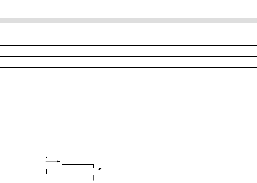
Instruction Manual
D103412X012
Field Communicator Menu Structure
January 2015
243
Transducer Block (TB) Menu Structure (Continued)
Menu StructureParameter Label
Trim Style 2 TB > Configure/Setup > Detailed Setup > Valve and Actuator > Reference > Trim Style 2
Unbalanced Area TB > Configure/Setup > Detailed Setup > Valve and Actuator > Trim > Unbalanced Area
Upper Bench Set TB > Configure/Setup > Detailed Setup > Valve and Actuator > Actuator > Upper Bench Set
Valve Class TB > Configure/Setup > Detailed Setup > Valve and Actuator > Valve > Valve Class
Valve Manufacturer TB > Configure/Setup > Detailed Setup > Valve and Actuator > Valve > Valve Manufacturer
Valve Model Number TB > Configure/Setup > Detailed Setup > Valve and Actuator > Valve > Valve Model Number
Valve Serial Number TB > Configure/Setup > Detailed Setup > Valve and Actuator > Valve > Valve Serial Number
Valve Size TB > Configure/Setup > Detailed Setup > Valve and Actuator > Valve > Valve Size
Valve Style TB > Configure/Setup > Detailed Setup > Valve and Actuator > Valve > Valve Style
Zero Power Condition TB > Configure/Setup > Detailed Setup > Instrument > Zero Power Condition
Basic Setup
Device Setup
Performance Tuner
Configure/Setup
Basic Setup
Detailed Setup
Calibration
TRANSDUCER BLOCK
BASIC SETUP
Top Level
Configure/Setup
Device Diagnostics
Device Variables
Instruction Manual
D103412X012
Field Communicator Menu Structure
January 2015
244
TRANSDUCER BLOCK
DETAILED SETUP
Top Level
Configure/Setup
Device Diagnostics
Device Variables
Detailed Setup
Transducer Block Mode
Protection
Response Control
Alerts
Instrument
Valve and Actuator
MAI Channel Map
Alert Handling
Response Control
Travel Tuning
Pressure Tuning
Travel Press Control
Input Characterization
Custom Characterization Table
Outblock Selection
Instrument
Tag Description
Pressure Units
Temperature Units
Travel Units
Length Units
Area Units
Spring Rate Units
:Relay Type
:Zero Power Condition
:Maximum Supply Pressure
Calibration Person
Calibration Location
Calibration Date
:Last Calibration Type
Travel Tuning
:Travel Tuning Set
Travel Proportional Gain
Travel Velocity Gain
:Travel MLFB Gain
:Travel Integral Enable
:Travel Integral Gain
:Travel Integral Dead Zone
:Travel Integral Limit Hi
:Travel Integral Limit Lo
Performance Tuner
Stabilize / Optimize
Pressure Tuning
:Pressure Tuning Set
:Pressure Proportional Gain
:Pressure MLFB Gain
:Pressure Integral Gain
:Pressure Integral Dead Zone
:Pressure Integral Limit Hi
:Pressure Integral Limit Lo
Travel Press Control
:Travel/Pressure State
:Travel/Pressure Select
Travel Deviation Pressure Fallback
Travel Cutoff Hi
Travel Cutoff Lo
:Pressure Cutoff Open
:Pressure Cutoff Closed
:Pressure Range Hi
:Pressure Range Lo
Alert Handling
PlantWeb Alert Simulate
Simulate Active Alerts
PlantWeb Alert Handling
Simulate Active Alarms
Failed Active
Maint Active
Advise Active
MAI Channel Map
:MAI Channel 1
:MAI Channel 2
:MAI Channel 3
:MAI Channel 4
:MAI Channel 5
:MAI Channel 6
:MAI Channel 7
:MAI Channel 8
PlantWeb Alert Handling
PlantWeb Alerts Set PV Status
Block Error Reporting
Configure/Setup
Basic Setup
Detailed Setup
Calibration
Alerts (See facing page)
Elect Alerts
Configuration Alerts
Sensor Alerts
Environment Alerts
Travel Alerts
Prox Alerts
Travel History Alerts
Performance Alerts
PlantWeb Alert Enable
PlantWeb Alert Reporting
Valve and Actuator
Valve
Trim
Actuator
Reference
Valve
Valve Manufacturer
Valve Model Number
Valve Serial Number
Valve Style
:Valve Size
:Valve Class
:Rated Travel
:Actual Travel
:Shaft Stem Diameter
:Packing Type
:Inlet Pressure
:Outlet Pressure
Trim
:Seat Type
:Leak Class
:Port Diameter
:Port Type
:Flow Direction
:Push Down To
:Flow Tends To
:Unbalanced Area
Actuator
Actuator Manufacturer
Actuator Model Number
:Actuator Style
Actuator Serial Number
:Actuator Size
Actuator Fail Action
:Feedback Connection
:Travel Sensor Motion
:Lever Style
:Lever Arm Length
:Effective Area
:Air
:Upper Bench Set
:Lower Bench Set
:Nominal Supply Pressure
:Spring Rate
Reference
:Trim Style 1
:Trim Style 2
:Stroke Time Open
:Stroke Time Close
Instruction Manual
D103412X012
Field Communicator Menu Structure
January 2015
245
TRANSDUCER BLOCK
DETAILED SETUP > ALERTS
(continued on next page)
Alerts
Elect Alerts
Configuration Alerts
Sensor Alerts
Environment Alerts
Travel Alerts
Prox Alerts
Travel History Alerts
Performance Alerts
PlantWeb Alert Enable
PlantWeb Alert Reporting
Drive Current
Drive Current
:Drive Current Alert
:Drive Current Alert Enable
:Drive Current Shutdown
:Drive Current Manual Recovery
:Drive Current Alert Point
:Drive Current Alert Time
Processor Impaired
:Program Memory Alert
:Program Memory Alert Enable
:Program Memory Shutdown
:Program Memory Manual Recovery
:Static Memory Alert
:Static Memory Alert Enable
:Static Memory Shutdown
:Static Memory Manual Recovery
:Processor Alert
:Processor Alert Enable
:I/O Processor Alert
:I/O Processor Alert Enable
:I/O Processor Shutdown
:I/O Processor Man Recovery
Elect Alerts
Drive Current
Drive Signal
Processor Impaired
Drive Signal
Drive Signal
:Drive Signal Alert
:Drive Signal Alert Enable
Output Block Timeout
:Output Block Timeout Alert
:Output Block Timeout Alert Enable
:Output Block Timeout Shutdown
:Output Block Timeout Manual Recovery
:Output Block Timeout
Configuration Alerts
Output Block Timeout
Blocks Set to Default
Alert Key
Blocks Set to Default
:Blocks Set to Defaults Alert
:Blocks Set to Defaults Alert Enable
Sensor Alerts
Travel Sensor
Pressure Sensors
Pressure Fallback
Temperature Sensor
Travel Sensor
:Travel Sensor Alert
:Travel Sensor Alert Enable
:Travel Sensor Shutdown
:Travel Sensor Manual Recovery
Pressure Sensors
:Pressure A Sensor Alert
:Pressure A Sensor Alert Enable
:Pressure A Sensor Shutdown
:Pressure A Sensor Manual Recovery
:Pressure B Sensor Alert
:Pressure B Sensor Alert Enable
:Supply Pressure Sensor Alert
:Supply Pressure Sensor Alert Enable
Pressure Fallback
:Pressure Fallback Alert
:Pressure Fallback Alert Enable
Temperature Sensor
:Temperature Sensor Alert
:Temperature Sensor Alert Enable
Supply Pressure
:Supply
:Supply Pressure Hi Alert
:Supply Pressure Hi Alert Enable
Supply Pressure Hi Alert Point
:Supply Pressure Lo Alert
:Supply Pressure Lo Alert Enable
:Supply Pressure Lo Alert Point
Environment Alerts
Supply Pressure
Temperature Limit
Temperature Limit
Temperature
:Temperature Hi Alert
:Temperature Hi Alert Enable
Temperature Hi Alert Point
:Temperature Lo Alert
:Temperature Lo Alert Enable
:Temperature Lo Alert Point
Instruction Manual
D103412X012
Field Communicator Menu Structure
January 2015
246
TRANSDUCER BLOCK
DETAILED SETUP > ALERTS
Prox Alerts
:Travel
Travel Open
Travel Closed
Proximity
Travel Open
Travel Open Alert
Travel Open Alert Enable
:Travel Open Alert Point
:Travel Open Deadband
Travel Closed
:Travel Closed Alert
:Travel Closed Alert Enable
:Travel Closed Alert Point
:Travel Closed Deadband
Proximity
:Proximity Hi Hi Alert
:Proximity Hi Hi Alert Enable
:Proximity Hi Alert
:Proximity Hi Alert Enable
:Proximity Lo Alert
:Proximity Lo Alert Enable
:Proximity Lo Lo Alert
:Proximity Lo Lo Alert Enable
Travel Alerts
:Travel Target
:Travel
Travel Deviation
Travel Limit
Travel Hi/Lo
Travel Deviation
Travel Deviation
:Travel Deviation Alert
:Travel Deviation Alert Enable
:Travel Deviation Alert Point
:Travel Deviation Time
:Travel Deviation Deadband
Travel Limit
:Travel Hi Hi Alert
:Travel Hi Hi Alert Enable
:Travel Hi Hi Alert Point
:Travel Hi Hi Deadband
:Travel Lo Lo Alert
:Travel Lo Lo Alert Enable
:Travel Lo Lo Alert Point
:Travel Lo Lo Deadband
Travel Hi/Lo
:Travel Hi Alert
:Travel Hi Alert Enable
:Travel Hi Alert Point
:Travel Hi Deadband
:Travel Lo Alert
:Travel Lo Alert Enable
:Travel Lo Alert Point
:Travel Lo Deadband
PlantWeb Alert Enable
Failed Enable
Maintenance Enable
Advise Enable
PlantWeb Alert Reporting
Failed Suppress
Maintenance Suppress
Advise Suppress
Performance Alerts
:PD Inside Status
:PD Run
Performance Critical
Performance Reduced
Performance Information
Performance Critical
Performance Critical Alert
Performance Critical Alert Enable
Performance Reduced
Performance Reduced Alert
Performance Reduced Alert Enable
Performance Information
Performance Information Alert
Performance Information Alert Enable
Travel History Alerts
Cycle Counter
Travel Accumulator
Cycle Counter
Cycle Counter
:Cycle Counter Alert
:Cycle Counter Alert Enable
:Cycle Counter Alert Point
:Cycle Counter Deadband
Travel Accumulator
Travel Accumulator
:Travel Accumulator Alert
:Travel Accumulator Alert Enable
:Travel Accumulator Alert Point
:Travel Accumulator Deadband
Alerts
Elect Alerts
Configuration Alerts
Sensor Alerts
Environment Alerts
Travel Alerts
Prox Alerts
Travel History Alerts
Performance Alerts
PlantWeb Alert Enable
PlantWeb Alert Reporting
Instruction Manual
D103412X012
Field Communicator Menu Structure
January 2015
247
TRANSDUCER BLOCK
CALIBRATION
Top Level
Configure/Setup
Device Diagnostics
Device Variables
Configure/Setup
Basic Setup
Detailed Setup
Calibration Calibration
Auto Calibration
Manual Calibration
Relay
Supply Pressure
Pressure A
Pressure B
Device Record
:Maximum Recorded Temperature
:Maximum Recorded Temperature Time
:Minimum Recorded Temperature
:Minimum Recorded Temperature Time
:Maximum Recorded Supply Pressure
:Maximum Recorded Supply Pressure Time
:Minimum Recorded Supply Pressure
:Minimum Recorded Supply Pressure Time
Device Diagnostics
Active PlantWeb Alerts
Alert Conditions
Status
Device Record
Stroke Valve
Trend
Status
Self Test Status
Block Error Self Test Status
Integrator Suspended
Integrator Limited Lo
Integrator Limited Hi
Travel Sensor Span Error
MLFB Error
Travel Sensor Hi Error
Travel Sensor Lo Error
Pressure B Sensor Failure
Pressure A Sensor Failure
Supply Sensor Failure
IOP Failure
Drive Current Alert
Simulate Jumper ON
Block Error
Block Configuration Error
Simulate Active
Lost Static Data
Device Needs Maintenance Now
Out of Service
TRANSDUCER BLOCK
DEVICE DIAGNOSTICS
Top Level
Configure/Setup
Device Diagnostics
Device Variables
TRANSDUCER BLOCK
DEVICE VARIABLES
Device Variables
All Block Modes
AO Control - Pre‐Char
AO Control - Post‐Char
DO Control
Input Characterization
:Travel/Pressure State
:PD Inside Status
Protection
Drive Signal
Temperature
Cycle Counter
Travel Accumulator
:Travel Count
Pressures
AO Control - Pre‐Char
:Setpoint
:Setpoint Status
:Travel (DeChar)
Pressures
:Supply
:Pressure A
:Pressure B
:A Minus B
AO Control - Post‐Char
:Travel Target
:Travel
:Travel Status
DO Control
:Setpoint(D)
:Travel(D)
Top Level
Configure/Setup
Device Diagnostics
Device Variables

Instruction Manual
D103412X012
Field Communicator Menu Structure
January 2015
248
Resource Block (RB) Menu Structure
Parameter Label Menu Structure
Alert Key RB > Configure/Setup > Alarm Handling > Alert Key
Block Alarm: Alarm State RB > Device Diagnostics > Block Alarm > Alarm State
Block Alarm: Unacknowledged RB > Device Diagnostics > Block Alarm > Unacknowledge
Block Alarm Disabled RB > Configure/Setup > Alarm Handling > Block Alarm Disabled
Block Alarm Automatically
Acknowledge RB > Configure/Setup > Alarm Handling > Block Alarm Automatically Acknowledge
Confirm Time RB > Configure/Setup > Alarm Handling > Confirm Time
DD Information RB > Device Variables > DD information
Device ID RB > Configure/Setup > Identification > Device ID or RB > Device Variables > Instrument > Identification > Device ID
Device Revision RB > Configure/Setup > Version > Device Revision or RB > Device Variables > Instrument > Version > Device Revision
Device State RB > Display > Resource Status > Device State
RB > Device Diagnostics > Device State
Device Type RB > Configure/Setup > Identification > Device Type or RB > Device Variables > Instrument > Identification > Device Type
Diagnostics Options RB > Configure/Setup > Options > Diagnostics Options
Discrete Alarm Disabled RB > Configure/Setup > Alarm Handling > Discrete Alarm Disabled
Discrete Alarm Automatically
Acknowledge RB > Configure/Setup > Alarm Handling > Discrete Alarm Automatically Acknowledge
Electronics Serial Number RB > Configure/Setup > Identification > Elect S/N or RB > Device Variables > Instrument > Identification > Electronics Serial Number
Factory Serial Number RB > Configure/Setup > Identification > Factory S/N or RB > Device Variables > Instrument > Identification > Factory Serial Number
Fault State RB > Device Diagnostics > Maintenance > Fault State
Features Available RB > Configure/Setup > Options > Features Available or RB > Device Variables > Options > Features Available
Features Selected RB > Configure/Setup >Options > Features Selected
Field Serial Number RB > Configure/Setup > Identification > Field S/N or RB > Device Variables > Instrument > Identification > Field Serial Number
Firmware Revision RB > Configure/Setup > Version > Firmware Revision or RB > Device Variables > Instrument > Version > Firmware Revision
Function Block Options RB > Configure/Setup > Options > Function Block Options or RB > Device Variables > Options > Function Block Options
Hardware Revision RB > Configure/Setup > Version > Hardware Revision or RB > Device Variables > Instrument > Version > Hardware Revision
ITK Version RB > Configure/Setup > Version > ITK Version or RB > Device Variables > Instrument > Version > ITK Version
Limit Notify RB > Configure/Setup > Alarm Handling > Limit Notify
Manufacturer RB > Configure/Setup > Identification > Manufacturer or RB > Device Variables > Instrument > Identification > Manufacturer
Maximum Notify RB > Configure/Setup > Alarm Handling > Maximum Notify
Miscellaneous Options RB > Configure/Setup > Options >Miscellaneous Options or RB > Device Variables > Options >Miscellaneous Options
Resource Block Error RB > Device Diagnostics > Resource Block Error
Shed Remote Cascade RB > Configure/Setup > Communication Time Out > Shed Remote Cascade
Shed Remote Out RB > Configure/Setup > Communication Time Out > Shed Remote Out
Standby Firmware Revision RB > Configure/Setup > Version > Standby Software Revision or RB > Device Variables > Instrument > Version > Standby Software
Revision
Strategy RB > Configure/Setup > Identification > Strategy or RB > Device Variables > Instrument > Identification > Strategy
Tag Description RB > Configure/Setup > Identification > Tag Description or RB > Device Variables > Instrument > Identification > Tag Description
Write Alarm: Alarm State RB > Device Diagnostics > Write Lock > Write Alarm: Alarm State
Write Lock RB > Configure/Setup > Write Lock > Write Lock or RB > Device Diagnostics > Write Lock > Write Lock
Write Priority RB > Configure/Setup > Write Lock > Write Priority

Instruction Manual
D103412X012
Field Communicator Menu Structure
January 2015
249
RESOURCE BLOCK
CONFIGURE/SETUP
Alarm Handling
Alert Key
Confirm Time
Limit Notify
Maximum Notify
Block Alm Disabled
Block Alarm Auto Acknowledge
Disc Alm Disabled
Discrete Alarm Auto Acknowledge
Write Lock
Write Lock
Write Priority
Comm Timeout
Shed Remote Cascade
Shed Remote Out
Options
Diagnostics Options
Function Block Options
Miscellaneous Options
Features Available
Features Selected
Function
Block Options
AO
DO
AI
DI
PID
IS
OS
MAI
Miscellaneous Options
Firmware Download
Travel Control Capable
Pressure Control Capable
Pressure Fallback Capable
Features Available
Reports
Fault State
Soft W Lock
Multi‐bit Alarm (Bit‐Alarm) Support
Features Selected
Reports
Fault State
Soft W Lock
Multi‐bit Alarm (Bit‐Alarm) Support
Identification
Device ID
Electronics Serial Number
Factory Serial Number
Field Serial Number
Tag Description
Strategy
Manufacturer
Device Type
Diagnostics Options
Version
Device Revision
Firmware Revision
Standby Firmware Revision
Hardware Rev
ITK Version
Configure/Setup
Resource Block Mode
Write Lock
Comm Timeout
Options
Alarm Handling
Identification
Version
Top Level
Configure/Setup
Device Diagnostics
Device Variables
Device Diagnostics
Resource Block Error
Device State
Write Lock
Block Alarm
Maintenance
Resource Block Error
Other
Block Configuration Error
Simulate Active
Device Needs Maintenance Soon
Memory Failure
Lost Static Data
Lost NV Data
Device Needs Maintenance Now
Power Up
Out of Service
Block Alarm
Block Alarm Alarm State
Block Alarm Unacknowledged
Maintenance
Restart Actions
Fault State
Set Fault State
Clear Fault State
Write Lock
Write Alarm Alarm State
Write Lock
Top Level
Configure/Setup
Device Diagnostics
Device Variables
RESOURCE BLOCK
DEVICE DIAGNOSTICS
Top Level
Configure/Setup
Device Diagnostics
Device Variables
Function
Block Options
AO
DO
AI
DI
PID
IS
OS
MAI
Instrument
Identification
Version
Version
Device Revision
Firmware Revision
Standby Firmware Revision
Hardware Rev
ITK Version
Options
Diagnostics Options
Function Block Options
Miscellaneous Options
Features Available
Features Available
Reports
Fault State
Soft W Lock
Multi‐bit Alarm (Bit‐Alarm) Support
Device Variables
Instrument
Options
DD Information
Miscellaneous Options
Firmware Download
Travel Control Capable
Pressure Control Capable
Pressure Fallback Capable
Identification
Device ID
Electronics Serial Number
Factory Serial Number
Field Serial Number
Tag Description
Strategy
Manufacturer
Device Type
RESOURCE BLOCK
DEVICE VARIABLES

Instruction Manual
D103412X012
Field Communicator Menu Structure
January 2015
250

Instruction Manual
D103412X012
PlantWeb Alerts
January 2015
251
Appendix C PlantWeb AlertsC‐C‐
Instrument Alert Conditions
Instrument Alert Conditions, when enabled, detect many operational and performance issues that may be of interest.
To view these alerts, the user must open the appropriate status screen on a host such as a DeltaV system, ValveLink
software or a Field Communicator.
PlantWeb Alerts
Some instrument alert conditions can also be used to trigger PlantWeb alerts that will be reported in Failed,
Maintenance or Advisory categories, as configured by the user. PlantWeb alerts, when enabled, can participate in the
DeltaV alarm interface tools such as the alarm banner, alarm list and alarm summary. For specific information on
setting up PlantWeb Alerts in a DeltaV system, refer to the PlantWeb Alerts section in Appendix F.
When a PlantWeb alert occurs, the DVC6200f sends an event notification and waits a specified period of time for an
acknowledgment to be received. This occurs even if the condition that caused the alert no longer exists. If the
acknowledgment is not received within the pre‐specified time‐out period, the event notification is retransmitted. This
reduces the possibility of alert messages getting lost.
Mode‐Based PlantWeb Alerts
Some PlantWeb alerts are not active unless the transducer block (actual) mode is Auto.
1. Alerts which can be triggered by the activities of the service technician are reported only when the transducer block
mode is AUTO.
2. Alerts which are unrelated to service technician activities are reported in all transducer block modes.
Exceptions are as follows:
Alerts can be simulated regardless of transducer block mode but must be enabled to be reported.
When a shutdown condition exists (either currently active or latched on through the shutdown recovery parameter)
in the transducer block, alerts are reported even though the mode of the transducer block is OOS.
Refer to table C‐1 for reporting of PlantWeb Alerts.
Alert Handling
Alert handling is diagrammed in figure C‐1. There are two ways of seeing PlantWeb alerts. One way is to see if the
instrument alert condition causing a PlantWeb alert is detected. The second is to view alerts reported to the system
operator console. For a PlantWeb alert to be active, it has to pass four tests. The first is to check if the Instrument alert
condition is enabled. If a condition is not enabled, the instrument does not check for the alert condition.
Second, the condition that will cause an alert must exist. For example, the current travel is above the Travel Limit Hi
Alert Point.
Third, the corresponding PlantWeb alert must be enabled in one or more of the three categories: Failed, Maintenance
or Advise.
Fourth, the transducer block mode must be correct. See table C‐1.
Note
Additional details on setting up and using Instrument Alerts can be found on page 45 of this manual.
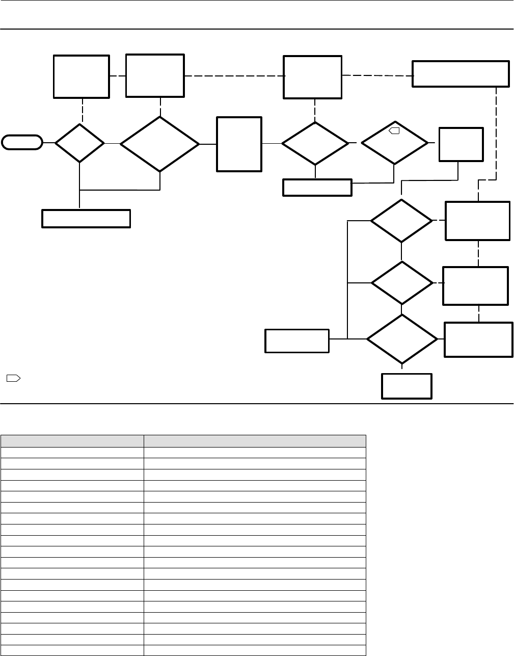
Instruction Manual
D103412X012
PlantWeb Alerts
January 2015
252
Figure C‐1. Alert Handling
START
ALERT
CONDITION
ENABLED?
Enable Instrument
Alert Condition in
the Transducer
Block
LIMITS EXCEEDED TO
CAUSE ALERT?
Set Alert Points
and Deadband in
the Transducer
Block
PLANTWEB
ALERT ACTIVE
PRIORITY
>1?
Set Priority with
PlantWeb Alarm
Priority parameters in
Transducer Block using
DeltaV
REPORT
ALERTS?
Select “Reports
Supported” from
FEATURE_SEL in the
Resource Block
Yes Yes
NO ACTIVE INSTRUMENT
ALERT CONDITION
No No
SUPPRESS
REPORTINGAL
ERT
CONDITION?
PLANTWEB
ALERTS
REPORTED
Suppress Alert
Condition Reporting
with Alarm Suppress
Parameters in
Transducer Block
Instrument Alert
Conditions active,
but not reported
Yes
Yes
Yes
No
No
No
Use Resource and Transducer
Block Parameters to Configure
Enable PlantWeb
Alert in the
Transducer Block
PLANTWEB
ALERT
ENABLED?
Yes
No
NO ACTIVE
PLANTWEB ALERT
INSTRUMENT
ALERT
CONDITION
ACTIVE
TRANSDUCER
BLOCK MODE
AUTO
Yes
A
B
B
B
B
B
B
A
"""""
1
1
NOTE:
CERTAIN PLANTWEB ALERTS ARE MODE‐BASED.
SEE TABLE C‐1 FOR DETAILS.
Yes
"
B
No
Table C‐1. PlantWeb Alerts Reporting Requirements
PlantWeb Alert Transducer Block Mode (Actual)
Drive Current AUTO
Drive Signal AUTO
Processor Impaired Any Mode
Output Block Timeout Any Mode
Block Set to Defaults Any Mode
Travel Sensor AUTO
Output Pressure Sensor Any Mode
Supply Pressure Sensor Any Mode
Temperature Sensor Any Mode
Supply Pressure AUTO
Temperature Limit AUTO
Travel Deviation AUTO
Travel Limit AUTO
Cycle Counter AUTO
Travel Accumulator AUTO
Performance Critical AUTO
Performance Reduced AUTO
Performance Information AUTO
Pressure Fallback AUTO

Instruction Manual
D103412X012
PlantWeb Alerts
January 2015
253
Alert Reporting
For PlantWeb alerts to be reported to the operator console, they must pass four tests:
Alerts must be active
Reports must be selected in Feature Select
Alert priority must be greater than 1
Reporting must not be suppressed for those conditions that caused active alerts.
Features Selected in the Resource block determines if reporting by the instrument is supported. Refer to page 23 for
additional information on Features Selected.
Failed Priority (FAILED_PRI [68]), Maintenance Priority (MAINT_PRI [69]), and Advise Priority (ADVISE_PRI [70])
determine the PlantWeb alert priorities. Although 16 priorities are available only three are actually meaningful for
PlantWeb alerts. If the priority is 0, no reporting occurs. If the priority is 1, reporting is simulated within the
instrument, but the alert is not actually reported over the bus. The alert condition is reported for priorities 2 through
15, with the higher priorities taking precedence over the lower priorities.
Failed Suppress (FAILED_MASK [65]), Maintenance Suppress (MAINT_MASK [66]), and Advise Suppress (ADVISE_MASK
[67]) determine which of the alert conditions are suppressed so that they are not reported.
PlantWeb Alerts Set Block Status
If a PlantWeb Alert is active, the AO or DO Block Readback parameter status may change. This behavior is controlled
with the PlantWeb Alerts Set PV Status (PWA_SET_STATUS [97]) parameter in the transducer block
Setting PlantWeb Alerts
Refer to table C‐2 for information on setting PlantWeb alerts. When selected, PlantWeb alarms will set the PV status
according to table C‐4.
Using PlantWeb Alerts
Refer to table C‐3 for information on using PlantWeb alerts.

Instruction Manual
D103412X012
PlantWeb Alerts
January 2015
254
Table C‐2. Setting PlantWeb Alerts
PlantWeb Alert
(Group)
(Default Alert Category)
Alert Condition
(Default) What the Alert is Detecting Related Parameters
(Default) Guidelines for Setting
Drive Current
(Electronics)
(Failed)
Drive Current
(Enabled)
The difference between the
expected Drive Current and the
actual Drive Current has
exceeded the Drive Current
Alert Time.
Self Test Shutdown (No)
Shutdown Recovery (Auto)
Alert Point (50%)
Alert Time (5 sec)
Use default settings
Drive Signal
(Electronics)
(Maintenance)
Drive Signal
(Enabled)
If one of the following
conditions exist:
Where Zero Power Condition is
defined as closed:
Drive Signal < 10% and
Calibrated Travel > 3%
Drive Signal > 90% and
Calibrated Travel < 97%
Where Zero Power Condition is
defined as open:
Drive Signal < 10% and
Calibrated Travel < 97%
Drive Signal > 90% and
Calibrated Travel > 3%
Use default setting
Processor Impaired
(Electronics)
(Maintenance)
Program Memory
(Enabled)
A pending Flash or NVM failure
is present.
Self Test Shutdown (No)
Shutdown Recovery (Auto) Use default settings
Static Memory
(Enabled)
A failure of the FRAM memory
where static parameters are
stored.
Self Test Shutdown (No)
Shutdown Recovery (Auto) Use default settings
Processor
(Enabled) A failure of the main Processor. Self Test Shutdown (No)
Shutdown Recovery (Auto) Use default settings
I/O Processor
(Enabled) A failure of the I/O Processor. Self Test Shutdown (No)
Shutdown Recovery (Auto) Use default settings
Output Block Timeout
(Configuration)
(Maintenance)
Output Block
Timeout
(Disabled)
If the analog or discrete output
block has not executed for
longer than the configured
timeout.
Timeout Alert Point (600 s)
Self Test Shutdown (No)
Shutdown Recovery (Auto)
Enable this alert for loops where the
execution is critical. If the AO or DO block
is not scheduled, or scheduled incorrectly,
it will trigger an alert after the Timeout
Alert Point has been exceeded. Set the
Timeout Alert Point to a value between
a. 30 seconds and
b. the maximum time before a user
should be notified. The minimum number
depends on the time it takes for a host to
download a configuration to the device.
Shutdown can be enabled if it is desired to
move the valve to the Zero Power
Condition at the same time that the alert
is generated.
Blocks Set to Default
(Configuration)
(Maintenance)
Blocks Set to Default
(Enabled)
If the resource block has
undergone Restart with
Defaults
None Use default settings
Shutdown Alert
(Configuration)
(Maintenance)
N/A
A user configured Self Test
Shutdown condition has taken
the instrument to OOS.
None Use default settings
-Continued-

Instruction Manual
D103412X012
PlantWeb Alerts
January 2015
255
Table C‐2. Setting PlantWeb Alerts (Continued)
PlantWeb Alert
(Group)
(Default Alert Category)
Alert Condition
(Default) What the Alert is Detecting Related Parameters
(Default) Guidelines for Setting
Travel Sensor
(Sensors)
(Failed)
Travel Sensor
(Enabled)
The travel feedback is within
acceptable limits.
Self Test Shutdown (No)
Shutdown Recovery (Auto)
Double Acting Actuators— Enable the
alert and configure it to report in the
Failed Alert Category. Self Test Shutdown
is generally not enabled.
Single Acting Actuators—
If Travel / Pressure Control is configured
as Travel with Pressure Fallback: enable
the alert and configure it to report in the
Maintenance Alert Category. Do not
enable Self Test Shutdown.
IIf Travel / Pressure Control is configured
as Travel: Enable the alert and configure it
to report in the Failed Alert Category. Self
Test Shutdown is generally not enabled.
Output Press Sensor
(Sensors)
(Maintenance)
Port A Pressure
Sensor (Enabled) The pressure sensor reading is
outside the functional range of
the sensor.
Self Test Shutdown (No)
Shutdown Recovery (Auto)
If Travel / Pressure Control is configured
as Pressure: enable the alert and
configure it to report in the Failed Alert
Category. Enable the Self Test Shutdown.
For all other Travel / Pressure Control
selections, enable the alert to report in
the Maintenance Alert Category and do
not enable the Self Test Shutdown.
Port B Pressure
Sensor (Enabled) None Use default settings
Supply Press Sensor
(Sensors)
(Advisory)
Supply Press Sensor
(Enabled)
The pressure sensor reading is
outside the functional range of
the sensor.
None Use default settings
Temperature Sensor
(Sensors)
(Advisory)
Temperature Sensor
(Enabled)
The temperature sensor
reading is outside the
functional range of the sensor.
None Use default settings
Pressure Fallback (Sensors)
(Maintenance)
Pressure Fallback
(Enabled)
A travel sensor failure or large
travel deviation has resulted in
fallback to pressure control.
None Use default settings
Supply Pressure
(Environment)
(Maintenance)
Supply Press High
(Enabled)
The supply pressure has
exceeded the Supply Pressure
Hi Alert Point.
Alert Point (145 psig)
Enable the alert in the Maintenance Alert
Category. Set the Alert Point to which
ever is lower of
a. the maximum instrument pressure of
145 psig or
b. the maximum actuator casing
pressure.
Supply Press Low
(Enabled)
The supply pressure is lower
than the Supply Pressure Lo
Alert Point.
Alert Point (19 psig)
Enable the alert in the Maintenance Alert
Category.
Double Acting Actuators— Set the Alert
Point above the minimum required for
valve shutoff and no greater than
1 psig below the supply regulator setting
Single Acting Actuators— Set the Alert
Point above the minimum required for
valve shutoff and no greater than
1 psig below the supply regulator setting.
This is generally about 3 psig above the
actuator upper bench set (stroking)
pressure.
-Continued-

Instruction Manual
D103412X012
PlantWeb Alerts
January 2015
256
Table C‐2. Setting PlantWeb Alerts (Continued)
PlantWeb Alert
(Group)
(Default Alert Category)
Alert Condition
(Default) What the Alert is Detecting Related Parameters
(Default) Guidelines for Setting
Temperature Limit
(Environment)
(Advisory)
Temperature High
(Enabled)
The temperature is greater
than the Temperature Hi Alert
Point.
Alert Point ( 186F)
Use default settings
Other alert points may be chosen to
indicate changes in the instrument
environment.
Temperature Low
(Enabled)
The temperature is lower than
the Temperature Lo Alert
Point.
Alert Point ( -63F)
Enable the alert in the Maintenance Alert
Category. Set the Alert Point at -40F if
the instrument uses Nitrile elastomers
and -63F if it uses Fluorosilicone
elastomers.
Other alert points may be chosen to
indicate changes in the instrument
environment.
Travel Deviation
(Travel)
(Maintenance)
Travel Deviation
(Enabled)
The Travel Deviation has
exceeded the Travel Deviation
Alert Point by more than the
Travel Deviation Time.
Alert Point (5%)
Alert Time (10 sec)
Deadband (2%)
Enable the alert in the Maintenance Alert
Category. Use the default settings with
valves that are 4 inch and smaller with
PTFE packing systems.
With other valves, the user can refine the
settings with ValveLink software Dynamic
Error Band and Step Response Tests. Set
the related parameters as follows:
Tvl Dev Alert Point—set equal times 2 the
Maximum Dynamic Error, minimum 3%
Tvl Dev DB—set equal to the Dynamic
Error Band, minimum 2%
Tvl Dev Time—set equal to the T98 time
for a Step Test from 0 to 100% Travel,
minimum 10 seconds.
Travel Limit
(Travel)
(Advisory)
Travel Limit Hi Hi
(Disabled)
The Travel has exceeded the
Travel Limit Hi Hi Alert Point
Alert Point (125%)
Deadband (5%)
Enable this alert for critical loops, where it
is important to alert an operator if the
valve is approaching the wide open
position. A typical setting might be 95%.
Travel Limit Lo Lo
(Disabled)
The Travel is lower than the
Travel Limit Lo Lo Alert Point.
Alert Point (-25%)
Deadband (5%)
Enable this alert for critical loops, where it
is important to alert an operator if the
valve is approaching the closed position.
A typical setting might be 5%.
N/A
(Travel)
(N/A)
Travel Limit Hi
(Disabled)
The Travel has exceeded the
Travel Limit Hi Alert Point.
Alert Point (125%)
Deadband (5%)
Use the Alert Points and Deadband to
configure the Proximity Alerts below.
Travel Limit Lo
(Disabled)
The Travel is lower than the
Travel Limit Lo Alert Point.
Alert Point (-25%)
Deadband (5%)
Use the Alert Points and Deadband to
configure the Proximity Alerts below.
N/A
(Proximity)
(N/A)
Travel Open
(Disabled)
The Travel is greater than the
Open Alert Point
Alert Point (99.5%)
Deadband (5%)
Enable and set to report Travel with DI
Block
Travel Closed
(Disabled)
The Travel is greater than the
Closed Alert Point
Alert Point (0.5%)
Deadband (5%)
Enable and set to report Travel with DI
Block
Proximity Hi Hi
(Disabled)
The Travel is within the
configured band of the
configured center point.
Alert Point (125%)
Deadband (5%)
Enable and set to report Travel with DI
Block
Proximity Hi
(Disabled)
Alert Point (125%)
Deadband (5%)
Enable and set to report Travel with DI
Block
Proximity Lo
(Disabled)
Alert Point (-25%)
Deadband (5%)
Enable and set to report Travel with DI
Block
Proximity Lo Lo
(Disabled)
Alert Point (-25%)
Deadband (5%)
Enable and set to report Travel with DI
Block
Cycle Counter
(Travel History)
(Maintenance)
Cycle Counter
(Disabled)
The number of travel reversals
has exceeded the configured
limit.
Alert Point (1,000,000)
Deadband (1%)
Bellows Seal Bonnets— enable the alert in
the Maintenance Alert Category. Use the
bellows manufacturer's cycle life data to
set cycle limits.
-Continued-

Instruction Manual
D103412X012
PlantWeb Alerts
January 2015
257
Table C‐2. Setting PlantWeb Alerts (Continued)
PlantWeb Alert
(Group)
(Default Alert Category)
Alert Condition
(Default) What the Alert is Detecting Related Parameters
(Default) Guidelines for Setting
Travel Accumulator
(Travel History)
(Maintenance)
Travel Accumulator
(Disabled)
The accumulated travel has
exceeded the configured limit.
Alert Point (1,000,000)
Deadband (1%)
Packing Bonnets— enable the alert in the
Maintenance Alert Category. When
packing leaks are discovered, set the
Travel Accumulator alert to 90% of the
current Travel Accumulator Value,
triggering an alert prior to anticipated
leak.
Performance Critical
(Performance)
(Failed)
Performance Critical
(Enabled)
Critical performance issues
based on continuous PD tests
internal to the instrument.
None Use default setting
Performance Reduced
(Performance)
(Maintenance)
Performance
Reduced
(Enabled)
Reduced performance issues
based on continuous PD tests
internal to the instrument.
None Use default setting
Performance Information
(Performance)
(Advisory)
Performance
Information
(Enabled)
Performance Information
based on continuous PD tests
internal to the instrument.
None Use default setting
Table C‐3. Using PlantWeb Alerts
PlantWeb Alert
(Group)
(Default Alert Category
Alert Condition
(Default) What the Alert is Detecting Effect on Valve/Instrument Recommended
Action Help
Drive Current
(Electronics)
(Failed)
Drive Current
(Enabled)
The difference between the
expected Drive Current and the
actual Drive Current has
exceeded the Drive Current
Alert Time.
If configured for Self Test
Shutdown, then the transducer
Actual mode is placed Out of
Service until the problem is
fixed. Out of Service results in
the instrument output
pressure(s) and actuator
position being at the Zero
Power Condition.
Check I/P module The instrument has
detected that the
difference between the
expected Drive Current
and the actual Drive
Current is greater than
the configured limit
1) Replace the I/P
module
2) Calibrate the device.
If the problem persists,
replace the printed
wiring board (PWB)
assembly.
Drive Signal
(Electronics)
(Maintenance)
Drive Signal
(Enabled)
If one of the following
conditions exist:
Where Zero Power Condition is
defined as closed:
Drive Signal < 10% and
Calibrated Travel > 3%
Drive Signal > 90% and
Calibrated Travel < 97%
Where Zero Power Condition is
defined as open:
Drive Signal < 10% and
Calibrated Travel < 97%
Drive Signal > 90% and
Calibrated Travel > 3%
None - Indicates reduced
performance.
Check instrument
pneumatics
The instrument I/P
drive signal necessary
to generate the
pressure output from
the instrument is not
within the expected
range. Potential causes
include I/P filter
plugged, instrument
pneumatic relay failure,
low supply pressure, air
leaks, or valve sticking.
Test the control valve
assembly for proper
operation. ValveLink
diagnostics can be used
for this purpose.
-Continued-

Instruction Manual
D103412X012
PlantWeb Alerts
January 2015
258
Table C‐3. Using PlantWeb Alerts (Continued)
PlantWeb Alert
(Group)
(Default Alert Category
Alert Condition
(Default) What the Alert is Detecting Effect on Valve/Instrument Recommended
Action Help
Processor Impaired
(Electronics)
(Maintenance)
Program Memory
(Enabled)
A pending Flash or NVM failure
is present.
If configured for Self Test
Shutdown, then the transducer
Actual mode is placed Out of
Service until the problem is
fixed. Out of Service results in
the instrument output
pressure(s) and actuator
position being at the Zero
Power Condition.
Replace PWB
assembly
An error has been
detected in the printed
wiring board (PWB)
assembly. Replace the
PWB assembly.
Static Memory
(Enabled)
A failure of the FRAM memory
where static parameters are
stored.
Processor
(Enabled)
A failure of the main Processor.
I/O Processor
(Enabled)
A failure of the I/O Processor.
Output Block Timeout
(Configuration)
(Maintenance
Output Block
Timeout
(Disabled)
If the AO or DO block has not
executed for longer than the
configured timeout, this alert is
detected.
If configured for Self Test
Shutdown, then the transducer
Actual mode is placed Out of
Service until the problem is
fixed. Out of Service results in
the instrument output
pressure(s) and actuator
position being at the Zero
Power Condition.
Check Output
Block
The function block
providing the setpoint
for the valve position
(AO or DO function
block) has not executed
within the user
configured time limit. If
configured for Self Test
Shutdown, the
transducer Actual
mode is set to Out of
Service.
1) Download the
control schedule from
the host configuration
device.
2) Make sure the Time
Out Alert Point is
greater than the block
execution schedule.
This alert should only
be utilized in very
critical loops where
execution time is
critical.
Blocks Set to Default
(Configuration)
(Failed)
Blocks Set to
Default
(Enabled)
If the resource block has
undergone Restart with
Defaults.
The transducer “Actual” mode
is placed Out of Service when
the defaults are applied. Out of
service results in the actuator
being at the Zero Power
Condition.
Download device
configuration
When restoring power
to the device, the
configuration
parameters could not
be recalled from
non‐volatile memory.
When the instrument
detects this condition,
the transducer Actual
mode is set to Out of
Service.
To correct this
situation, download the
configuration to the
device and set the
Target Mode of the
Resource block.
Shutdown Alert
(Configuration)
(Failed)
N/A A user configured Self Test
Shutdown condition has taken
the instrument to OOS.
None - Indicates why the
instrument remains OOS.
Same as the
configured Self
Test Shutdown.
The instrument Actual
mode remains OOS due
to a configured Self
Test Shutdown, where
Manual Recovery was
specified, even though
the condition may have
cleared. Check
Recommended Action
for the indicated
condition.
-Continued-

Instruction Manual
D103412X012
PlantWeb Alerts
January 2015
259
Table C‐3. Using PlantWeb Alerts (Continued)
PlantWeb Alert
(Group)
(Default Alert Category
Alert Condition
(Default) What the Alert is Detecting Effect on Valve/Instrument Recommended
Action Help
Travel Sensor
(Sensors)
(Failed)
Travel Sensor
(Enabled)
The travel feedback is within
acceptable limits.
If configured for Self Test
Shutdown, then the transducer
“Actual” mode is placed Out of
Service until the problem is
fixed. Out of service results in
the actuator being at the Zero
Power Condition.
Check mounting
and linkage
Travel feedback value is
outside expected
limits. If this problem
occurs during
instrument set‐up, the
most likely cause is
faulty mounting or
improper adjustment
of the travel sensor. If
this problem occurs
during normal
operation, the most
likely cause is a failure
of the travel sensor.
To correct,
1) Insure proper
mounting and linkage
adjustment.
2) Inspect and test
travel sensor
3) Toggle the
transducer target
mode.
If the problem persists,
replace the printed
wiring board (PWB)
assembly.
Output Press Sensor
(Sensors)
(Maintenance)
Port A Pressure
Sensor (Enabled)
The pressure sensor reading is
outside the functional range of
the sensor.
If configured for Self Test
Shutdown, then the transducer
“Actual” mode is placed Out of
Service until the problem is
fixed. Out of service results in
the actuator being at the “No
Power” condition.
Confirm proper
air supply
The pressure sensor
on‐board the device
has failed. This may be
due to excessive supply
pressure or
contaminated air.
If it is verified that the
air supply is ok, replace
the printed wiring
board (PWB) assembly.
Port B Pressure
Sensor (Enabled)
None - Indicates a possible
hardware problem that would
degrade diagnostic capability.
Supply Press Sensor
(Sensors)
(Advisory)
Supply Press
Sensor (Enabled)
The pressure sensor reading is
outside the functional range of
the sensor.
None - Indicates a possible
hardware problem that would
degrade diagnostic capability.
Confirm proper
air supply
The pressure sensor
on‐board the device
has failed. This may be
due to excessive supply
pressure or
contaminated air.
If it is verified that the
air supply is ok, replace
the printed wiring
board (PWB) assembly.
Temperature Sensor
(Sensors)
(Advisory)
Temperature
Sensor (Enabled)
The temperature sensor
reading is outside the
functional range of the sensor.
None - Indicates a possible
hardware problem that would
degrade instrument calibration
and diagnostic capability.
Replace PWB
assembly.
The temperature
sensor on‐board the
device has failed or the
unit has been exposed
to an temperature
extreme beyond the
recommended limits.
-Continued-

Instruction Manual
D103412X012
PlantWeb Alerts
January 2015
260
Table C‐3. Using PlantWeb Alerts (Continued)
PlantWeb Alert
(Group)
(Default Alert Category
Alert Condition
(Default) What the Alert is Detecting Effect on Valve/Instrument Recommended
Action Help
Pressure Fallback
(Sensors)
(Maintenance)
Pressure Fallback
(Enabled)
A travel sensor failure or large
travel deviation has resulted in
fallback to pressure control.
None - Indicates a reduced
performance condition.
Check instrument
feedback linkage
and travel sensor.
The instrument has
detected that the travel
sensor is outside its
normal range of
operation or that a
gross deviation exists
between set point and
actual travel. It has
switched to Pressure
Control and is no
longer using the travel
sensor to position the
valve.
Supply Pressure
(Environment)
(Maintenance)
Supply Press High
(Enabled)
The supply pressure has
exceeded the Supply Pressure
Hi Alert Point.
None - Indicates a condition
that could cause damage to
the instrument or actuator.
Confirm proper
air supply.
The Supply Pressure
sensor on‐board has
detected an abnormally
high supply pressure.
Verify the proper
supply pressure and
that the alert is
properly set.
Supply Press Low
(Enabled)
The supply pressure is lower
than the Supply Pressure Lo
Alert Point.
None - Indicates a condition
that could reduce performance
or prevent the valve from
shutting tightly.
The Supply Pressure
sensor on‐board has
detected an abnormally
low supply pressure.
Verify the proper
supply pressure and
that the alert is
properly set.
Temperature Limit
(Environment)
(Advisory)
Temperature High
(Enabled)
The temperature is greater
than the Temperature Hi Alert
Point.
None - Indicates a condition
that could shorten service life
or lead to reduced
performance.
Check instrument
environment.
The instrument
temperature has
exceeded the user
configured high
temperature limit.
Operation of the
instrument above the
rated temperature may
degrade instrument
components. This may
affect instrument
performance and/or
reduce the life of the
instrument.
Temperature Low
(Enabled)
The temperature is lower than
the Temperature Lo Alert
Point.
The instrument
temperature has
dropped below the user
configured low
temperature limit.
Operation of the
instrument below the
rated temperature may
degrade instrument
components. This may
affect instrument
performance and/or
reduce the life of the
instrument.
-Continued-

Instruction Manual
D103412X012
PlantWeb Alerts
January 2015
261
Table C‐3. Using PlantWeb Alerts (Continued)
PlantWeb Alert
(Group)
(Default Alert Category
Alert Condition
(Default) What the Alert is Detecting Effect on Valve/Instrument Recommended
Action Help
Travel Deviation
(Travel)
(Maintenance)
Travel Deviation
(Enabled)
The Travel Deviation has
exceeded the Travel Deviation
Alert Point by more than the
Travel Deviation Time.
None - Indicates a reduced
performance condition.
Check valve
friction, supply
air, instrument
tuning
The valve travel is not
following setpoint.
Check operation of the
valve and instrument.
Possible items include;
sticking valve, low
supply pressure,
broken feedback
linkage, instrument
pneumatic
components, actuator,
instrument tubing,
poor instrument
tuning, etc.
Test the control valve
assembly for proper
operation. ValveLink
software diagnostics
can be used for this
purpose.
Travel Limit
(Travel)
(Advisory)
Travel Limit Hi Hi
(Disabled)
The Travel has exceeded the
Travel Limit Hi Hi Alert Point.
None Check process
loop
The actual valve
position has exceeded
the configurable travel
limit (in %).
Travel Limit Lo Lo
(Disabled)
The Travel is lower than the
Travel Limit Lo Lo Alert Point.
None Check process
loop
N/A
(Travel)
(N/A)
Travel Limit Hi
(Disabled)
The Travel has exceeded the
Travel Limit Hi Alert Point.
None Check process
loop
The actual valve
position has exceeded
the configurable travel
limit (in %).
Travel Limit Lo
(Disabled)
The Travel is lower than the
Travel Limit Lo Alert Point.
None Check process
loop
The actual valve
position has exceeded
the configurable travel
limit (in %).
N/A
(Proximity)
(N/A)
Travel Open
(Disabled)
The Travel is greater than the
Open Alert Point
None Check process
loop
The actual valve
position is near the full
open position.
Travel Closed
(Disabled)
The Travel is greater than the
Closed Alert Point
None Check process
loop
The actual valve
position is near the full
closed position.
Proximity Hi Hi
(Disabled)
The Travel is within the
configured band of the
configured center point.
None Check process
loop
The actual valve
position is near the
configured center
point.
Proximity Hi
(Disabled)
None
Proximity Lo
(Disabled)
None
Proximity Lo Lo
(Disabled)
None
Cycle Counter
(Travel History)
(Maintenance)
Cycle Counter
(Disabled)
The number of travel reversals
has exceeded the configured
limit.
None Perform periodic
maintenance
The cycle count limit
has been exceeded.
Perform periodic
maintenance. Check
packing, linkages,
diaphragms, seals, etc.
Travel Accumulator
(Travel History)
(Maintenance)
Travel
Accumulator
(Disabled)
The accumulated travel has
exceeded the configured limit.
None Perform periodic
maintenance
The travel accumulator
limit has been
exceeded. Perform
periodic maintenance.
Check packing,
linkages, diaphragms,
seals, etc.
-Continued-

Instruction Manual
D103412X012
PlantWeb Alerts
January 2015
262
Table C‐3. Using PlantWeb Alerts (Continued)
PlantWeb Alert
(Group)
(Default Alert Category
Alert Condition
(Default) What the Alert is Detecting Effect on Valve/Instrument Recommended
Action Help
Performance Critical
(Performance)
(Failed)
Performance
Critical
(Enabled)
Critical performance issues
based on continuous PD tests
internal to the instrument.
None - Indicates control has
been lost or severely reduced.
Check I/P, Relay,
Valve, Actuator
or Ext. Tubing as
indicated.
On‐board diagnostics
have detected a critical
performance issue that
may result in loss of
control or severe
reduction in control
performance. Check or
replace the component
indicated in the
possible cause detail.
Performance Reduced
(Performance)
(Maintenance
Performance
Reduced (Enabled)
Reduced performance issues
based on continuous PD tests
internal to the instrument.
None - Indicates reduced
performance.
Check I/P, Relay,
Valve, Actuator
or Ext. Tubing as
indicated.
On‐board diagnostics
have detected a
performance issue that
has reduced control
performance. Check or
replace the component
indicated in the
possible cause detail.
Performance Information
(Performance)
(Advisory)
Performance
Information
(Enabled)
Performance Information
based on continuous PD tests
internal to the instrument.
None - Indicates information
that may pertain to control
performance.
No action
required.
On‐board diagnostics
have detected an
abnormal performance
condition. No
immediate action
required.
Table C‐4. Output Block PV Status
FEATURE_SEL
PW Alarms Set PV Status
Transducer Mode,
Actual
Active PlantWeb
Alarms
AO / DO
PV Status
AO / DO PV
Substatus AO/DO PV Limit Substatus(1)
Enabled
OOS X Bad Device Failure Constant
Man X Bad Non‐specific Constant
Auto Fail Uncertain Subnormal See table C‐5
Auto Maint, no Fail Uncertain Non‐specific See table C‐5
Auto Advisory, no Fail, no Maint Good Advisory See table C‐5
Auto None Good Non‐Specific See table C‐5
Not Enabled
OOS X Bad Device Failure Constant
Man X Bad Non‐Specific Constant
Auto Fail Good Non‐Specific See table C‐5
Auto Maint, no Fail Good Non‐Specific See table C‐5
Auto Advisory, no Fail, no Maint Good Non‐Specific See table C‐5
Auto None Good Non‐Specific See table C‐5
NOTES:
X = No Effect
1. PV limit substatus reflects only READBACK limit substatus. SP limit substatus reflects only out block rate limits.
Table C‐5. Limit Sub Status
Out Block Transducer Mode In Cutoff Region Rate Limited Limit Sub‐Status
AO, DO OOS X X Constant
AO, DO MAN X X Constant
AO AUTO High X High Limited
AO AUTO Low X Low Limited
AO AUTO X High High Limited
AO AUTO X Low Low Limited
AO AUTO None None Not Limited
DO AUTO X High High Limited
DO AUTO X Low Low Limited
DO AUTO X None Not Limited
NOTE: X = No Effect

Instruction Manual
D103412X012
FOUNDATION fieldbus Communication
January 2015
263
Appendix D FOUNDATION fieldbus Communication9‐D‐D‐
DVC6200f digital valve controllers use the FOUNDATION fieldbus to communicate with other fieldbus instruments and
the control system. Fieldbus is an all digital, serial, two‐way communication system which interconnects “field”
equipment such as transmitters, digital valve controllers, and process controllers. Fieldbus is a local‐area network
(LAN) for instruments used in both process and manufacturing automation with built‐in capability to distribute the
control application across the network.
Function Block Overview
A fieldbus system is a distributed system composed of field devices and control and monitoring equipment integrated
into the physical environment of a plant or factory. Fieldbus devices work together to provide I/O and control for
automated processes and operations. The Fieldbus Foundation provides a framework for describing these systems as a
collection of physical devices interconnected by a fieldbus network. One of the ways that the physical devices are used
is to perform their portion of the total system operation by implementing one or more function blocks.
Function Blocks
Function blocks within the fieldbus device perform the various functions required for process control. Because each
system is different, the mix and configuration of functions are different. Therefore, the Fieldbus Foundation has
designed a range of function blocks, each addressing a different need: Analog Input Block (AI), Multiple Analog Input
(MAI), Discrete Input Block (DI), Manual Loader Block (ML), Bias/Gain Station Block (BG), Control Selector Block (CS), P,
PD Controller Block (PD), PID, PI, I Controller Block (PID), Ratio Station Block (RA), Analog Output Block (AO) and
Discrete Output Block (DO).
Function blocks perform process control functions, such as analog input (AI) and analog output (AO) functions as well
as proportional‐integral‐derivative (PID) functions. The standard function blocks provide a common structure for
defining function block inputs, outputs, control parameters, events, alarms, and modes, and combining them into a
process that can be implemented within a single device or over the fieldbus network. This simplifies the identification
of characteristics that are common to function blocks.
The Fieldbus Foundation has established the function blocks by defining a set of parameters used in all function blocks
called universal parameters. The Fieldbus Foundation has also defined a standard set of function block classes, such as
input, output, control, and calculation blocks. Each of these classes have a set of parameters established for it.
Additionally, they have published definitions for transducer blocks commonly used with standard function blocks.
Examples include temperature, pressure, level, and flow transducer blocks.
Fieldbus Foundation specifications and definitions allow vendors to add their own, extended parameters, as well as
their own algorithms. This approach permits extending function block definitions as new requirements are discovered
and as technology advances.
Each block has a tag name. Service personnel need only know the tag name of the block to access or change the
appropriate block parameters.
Input events may affect the operation of the algorithm. An execution control function regulates the receipt of input
events and the generation of output events during execution of the algorithm. Upon completion of the algorithm, the
data internal to the block is saved for use in the next execution, and the output data is snapped, releasing it for use by
other function blocks.
Once the inputs are snapped, the algorithm operates on them, generating outputs as it progresses. Algorithm
executions are controlled through the setting of internal parameters. Internal parameters do not appear as normal
input and output parameters. However, they may be accessed and modified remotely, as specified by the function
block.
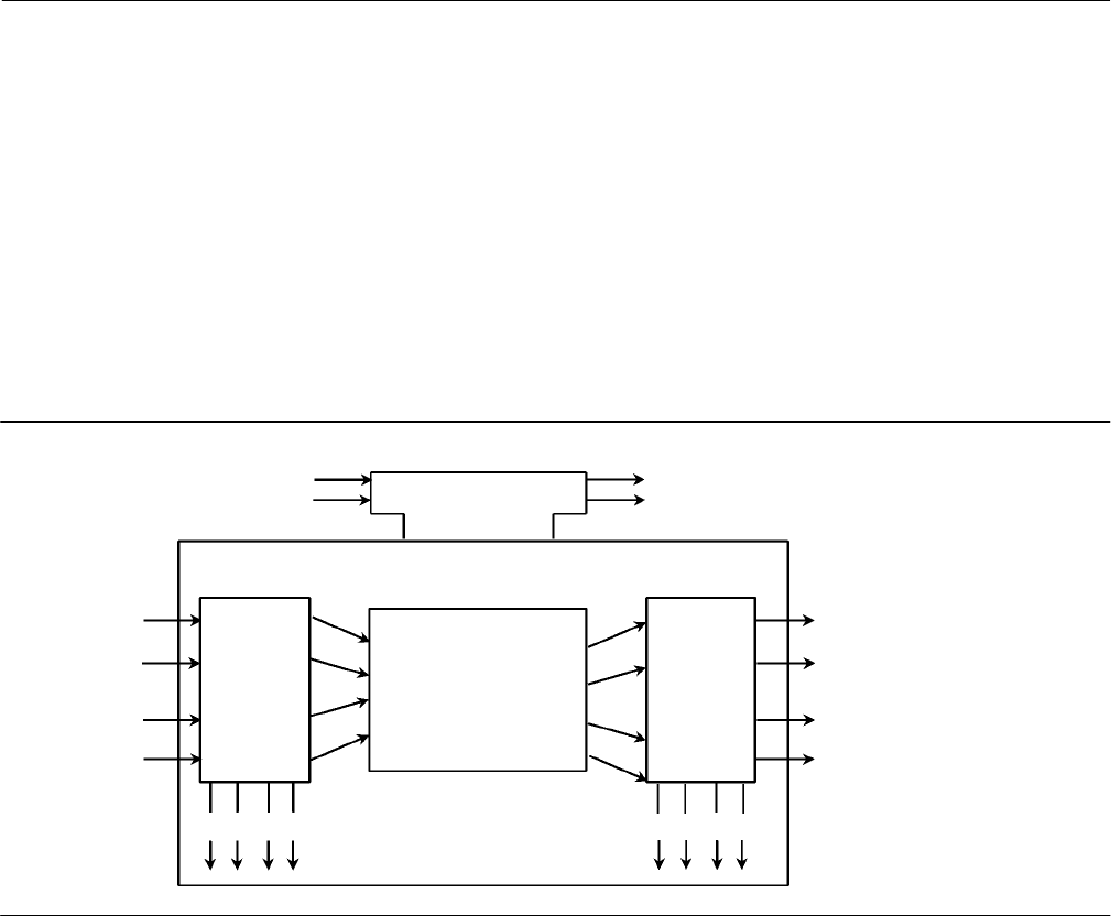
Instruction Manual
D103412X012
FOUNDATION fieldbus Communication
January 2015
264
Figure D‐1 illustrates the internal structure of a function block. When execution begins, input parameter values from
other blocks are snapped‐in by the block. The input snap process ensures that these values do not change during the
block execution. New values received for these parameters do not affect the snapped values and will not be used by
the function block during the current execution.
Function blocks are also capable of performing short‐term data collection and storage for reviewing their behavior.
Instrument‐Specific Blocks
In addition to function blocks, fieldbus devices contain two other block types to support the function blocks. These are
the resource block and the transducer block. The resource block contains the hardware specific characteristics
associated with a device. Transducer blocks couple the function blocks to local input/output functions.
Figure D‐1. Function Block Internal Structure
Input
Events
Output
Events
Processing
Algorithm
Output
Snap
Input
Snap
Input Parameter
Linkages
status status
Execution Control
Output
Parameter
Linkages
B2711
Resource Blocks
The resource block contains hardware specific characteristics associated with the device; it has no input or output
parameters. The algorithm within a resource block monitors and controls the general operation of the physical device
hardware. The execution of this algorithm is dependent on the characteristics of the physical device, as defined by the
manufacturer. As a result of this activity, the algorithm may cause the generation of events. There is only one resource
block defined for a device. For example, placing the resource block in Out of Service mode stops all function block
execution, by setting their modes to Out of Service as well. The actual mode of the function blocks is changed to Out
of Service, but the function block target modes will not change. Placing the resource block in the Out of Service mode
does not affect the mode of the transducer block.
Transducer Blocks
Transducer blocks connect function blocks to local input/output functions. They read sensor hardware and write to
effector (actuator) hardware. This permits the transducer block to execute as frequently as necessary to obtain good
data from sensors and ensure proper writes to the actuator without burdening the function blocks that use the data.
The transducer block also isolates the function block from the specific characteristics of the physical I/O.

Instruction Manual
D103412X012
FOUNDATION fieldbus Communication
January 2015
265
Block Modes
All blocks have modes. The mode determines the source of the set point, the destination of the output, how the block
executes, and the relationship between setpoint and output. The block mode is determined by the Block Mode
parameter. It is a structured parameter composed of the attributes actual, target, permitted, and normal. The
following defines each of the attributes.
Target mode—The Target mode is the mode requested by the user or host system. Only one mode is allowed to be
set and it must be a permitted mode as defined by the permitted attribute of the mode parameter.
Actual mode—This is the current mode of the block. The actual mode may differ from the target mode due to
operating conditions of the block.
Permitted mode—The permitted mode defines the modes allowed for the block. This is set by the user or host
system but is restricted by the instrument to modes supported by the instrument for the particular block. Any
change request to the Target or Normal attribute is checked against the permitted attribute to ensure the
requested mode is permitted.
When setting the Permitted mode, there is no check against any of the other attributes (Normal or Target modes).
Therefore, the normal or target mode attributes may have a value that is not permitted because the permitted
attribute was modified after the Normal or Target mode was set. This will have no effect on the instrument until the
user attempts to modify the Target or Normal mode. At this time these attributes are tested against the Permitted
modes, thus the user cannot change the Normal or Target modes to what was formerly permitted.
Normal mode—The normal mode is the mode the block should be in during normal operating conditions. The
normal mode is set by the user or host system and can only be set to a permitted mode (see permitted mode). The
user or host system can compare the actual mode to the normal mode and, based on the results, determine if the
block is operating normally.
Table D‐1 lists the modes supported by each block contained in the digital valve controller.
Table D‐1. DVC6200f Block Modes
Block Supported Mode Values
Resource Auto and OOS
Transducer Auto, Manual, and OOS
AO RCas, Cas, Auto, Man, LO(1), IMan(1), and OOS
PID ROut, RCas, Cas, Auto, Man, LO(1), IMan(1), and OOS
ISEL Auto, Man and OOS
OS IMan(1), Auto, Cas and OOS
AI Man, Auto, and OOS
MAI Man, Auto, and OOS
DO RCas, Cas, Auto, Man, LO(1), IMan(1), and OOS
DI Auto, Man, and OOS
1. This mode cannot be specified as a target mode.
Changing the block mode requires accessing the Block Mode parameter. For information on using the host system to
change the block mode via this parameter, see the appropriate host documentation.
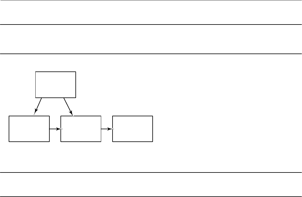
Instruction Manual
D103412X012
FOUNDATION fieldbus Communication
January 2015
266
Note
A downstream block changing to Out of Service impacts the mode of the upstream block. Refer to the block hierarchy in
figure D‐2.
Figure D‐2. Digital Valve Controller Block Hierarchy Example
TRANSDUCER
BLOCK
ANALOG OUTPUT
(AO) BLOCK
PID BLOCK
RESOURCE BLOCK
NOTES:
1. CHANGING THE RESOURCE BLOCK TO OUT OF SERVICE CHANGES ALL FUNCTION BLOCKS
TO OUT OF SERVICE, BUT DOES NOT AFFECT THE TRANSDUCER BLOCK.
2. CHANGING A DOWNSTREAM BLOCK TO OUT OF SERVICE AFFECTS THE UP STREAM BLOCK.
FOR EXAMPLE: WHEN THE TRANSDUCER BLOCK IS OUT OF SERVICE, THE AO BLOCK MODE
WILL CHANGE TO IMAN (INITIALIZE MANUAL).
Note
There is no mode associated with the FOUNDATION fieldbus Loop. Mode is dependent on the blocks within the Loop.
Explanation of Modes
Out of Service (OOS)—The functions performed by the block are not executed. If the block has any outputs, these
typically do not update and the status of any values passed to downstream blocks will be “BAD”. To make changes to
some of the parameters in a block requires that the block be Out of Service.
Initialization Manual (IMan)—Only the AO, DO, OS and PID blocks support this mode. When one of these blocks
detects a loss of a correct path to the downstream block (such as when the downstream block is in the OOS, Man, or
LO mode), it enters the IMan mode. For example, when the transducer block enters the OOS mode, the AO block
enters the IMan mode.
Local Override (LO)—Only the AO, DO, and PID blocks support this mode. If the PID block enters the LO mode, the
block output follows the tracking value (TRK_VAL), if external tracking is enabled by TRK_IN_D. In the AO and DO
block, the block enters LO mode when the block detects that fault state is active. In this case, the output is determined
by the selection for I/O_OPTS.
Manual (Man)—If the data status of a function block's input is bad or its target mode is Man, the block enters the
manual mode. In this mode, the function block does not update its OUT value. If the target is Man, the user may write
a desired value to the output.
Automatic (Auto)—The block performs the specified calculations based on the local set point and outputs the result,
independently without interfacing with another block. The user can write to the set point of a block in this mode. Any
block outputs continue to update.
Cascade (Cas)—The block performs the specified calculations based on the set point from another block via the
cascade input parameter and outputs the result. Any block outputs continue to update.

Instruction Manual
D103412X012
FOUNDATION fieldbus Communication
January 2015
267
Remote Output (ROut)—The block outputs are set to the value of the remote output parameter that is written by a
host computer or others. To prevent a sudden change in output, the block's calculations are initialized when a change
in mode occurs.
Remote Cascade (RCas)—The block performs the specified calculations based on a set point from a host computer or
others via the remote cascade input and outputs the result. If the block has any outputs, these continue to update.
Examples of Modes for Various Operational Statuses
Table D‐2 shows examples of block mode combinations in a digital valve controller (however it does not show all
combinations). When a block changes mode or the data status signal changes for some reason, the other blocks
connected to that block identify the change by detecting the change in status of an input signal, and change their
modes too. For example, when the data status of BKCAL_IN in a PID block changes to bad, the PID block automatically
changes its mode to Iman to initialize the control of its downstream block.
Table D‐2. Examples of Block Mode Combinations and Operational statuses for an Instrument with Standard Control
Operational Status Blocks
PID AO TB(1)
Initial Setup and calibration - - - OOS OOS
Modification of some transducer block parameters - - - IMan Manual
Constant valve position control - - - Auto Auto
PID Single‐loop control Auto Cas Auto
PID Cascade‐loop control Primary PID, Auto
Secondary PID, Cas Cas Auto
1. TB=Transducer Block
The respective modes to which each block should enter upon occurrence of a communication error and at a restart,
and the handling of signals in each mode may be defined in the block's option parameters such as IO_OPTS and
STATUS_OPTS. For details, see the detailed descriptions of each function block.
Device Descriptions
Device Descriptions are specified definitions that are associated with blocks. Device descriptions provide for the
definition and description of blocks and their parameters.
Device descriptions may also include a set of processing routines called Methods. Methods provide a procedure for
accessing and manipulating a series of parameters within a device, such as for setup and calibration. Methods are used
for a variety of functions including automatic calibration, setting protection and setting up the instrument. These
Methods are a predetermined sequence of steps for information required to setup, calibrate, and perform other
functions on the instrument.
Transducer Block Status and Limit Propagation
Every FOUNDATION fieldbus parameter has a value and a status. The status attribute is divided into three components:
Quality, Quality substatus, and a Limit. The Quality can be Good (Cascade), Good (Non‐Cascade), Uncertain, and Bad.
Each quality can have a substatus as shown in table D‐3. Each status attribute also has four possible limit states: Not
limited, Low limited, High limited, and Constant. Refer to the Fieldbus Foundation specifications for a more detailed
description. The following describes how the transducer block passes status information to the AO block. For
information on status handling by the function blocks within the digital valve controller, refer to the Detailed Setup
section.

Instruction Manual
D103412X012
FOUNDATION fieldbus Communication
January 2015
268
Table D‐3. Status Attribute Quality and Substatus Components
Quality Substatus
Good (NC) Non‐specific
Good (NC) Active Block Alarm
Good (NC) Active Advisory Alarm
Good (NC) Active Critical Alarm
Good (NC) Unack Block Alarm
Good (NC) Unack Advisory Alarm
Good (NC) Unack Critical Alarm
Uncertain Non‐specific
Uncertain Last Usable Value
Uncertain Substitute/Manual Entry
Uncertain Initial Value
Uncertain Sensor Conversion not Accurate
Uncertain Engineering Unit Range Violation
Uncertain Sub‐normal
Good (C) Non‐specific
Good (C) Initialization Acknowledge
Good (C) Initialization Request
Good (C) Not Invited
Good (C) Not Selected
Good (C) Local Override
Good (C) Fault State Active
Good (C) Initiate Fault State
Bad Non‐specific
Bad Configuration Error
Bad Not Connected
Bad Device Failure
Bad Sensor Failure
Bad No Comm, with LUV
Bad No Comm, no LUV
Bad Out of Service
(NC)=(Non‐cascade) (C)= (Cascade)
Status Propagation
The transducer block accepts the output from the AO block or DO block if the output parameter status is Good
(Non‐cascade) or Good (Cascade). When the AO or DO block is Out of Service the output parameter status is Bad. In
this case, the transducer block holds the last value.
If the transducer block actual mode is Out of Service, the AO block READBACK parameter status is Bad-Out of Service.
This could be caused by a Failed Alert. If a Failed Alert is active, the block error parameter (parameter name
BLOCK_ERR) for the Resource block will indicate Device Needs Maintenance Now. For more information on the
Resource and Transducer block error indications, refer to the Viewing Device Information section of this manual.
If the transducer block is functioning correctly the AO block READBACK parameter status is Good
(Non‐cascade)-Non‐specific. If a Maintenance or Advisory alert is active the substatus will reflect a Unacknowledged or
Active advisory alert. When a Maintenance or Advisory alert is active, the block error for the resource block indicates
Device Needs Maintenance Soon.
Limit Propagation
The following describes limit propagation:
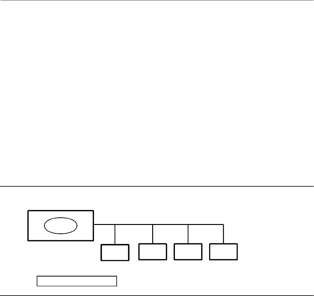
Instruction Manual
D103412X012
FOUNDATION fieldbus Communication
January 2015
269
AO Block
If the valve position is below the low cutoff value, the AO block READBACK status limit is LOW_LIMITED.
If the valve position is above the high cutoff value, the AO block READBACK status limit is HIGH_LIMITED.
If the transducer block actual mode is Auto and the above conditions are not true, the AO block READBACK status
limit is NOT_LIMITED.
If the transducer block actual mode is Out of Service, the AO block READBACK status limit is CONSTANT.
DO Block
If the transducer block actual mode is Auto, the DO block READBACK_D status is NOT_LIMITED.
If the transducer block actual mode is Out of Service, the DO block READBACK_D status is CONSTANT.
The control strategy should be configured to monitor the Analog Output block status and take action where
appropriate when the status is no longer Good.
Network Communication
Figure D‐3 illustrates a simple fieldbus network consisting of a single segment.
Figure D‐3. Simple Single‐Link Fieldbus Network
Fieldbus Segment
LINK MASTER
BASIC DEVICES
LAS = Link Active Scheduler
LAS
B2712‐1
Device Addressing
Fieldbus uses addresses between 0 and 255. Addresses 0 through 15 are typically reserved for group addressing and
for use by the data link layer. If there are two or more devices with the same address, the first device to start will use its
programmed address. Each of the other devices will be given one of four temporary addresses between 248 and 251. If
a temporary address is not available, the device will be unavailable until a temporary address becomes available.
Commission devices use addresses 20-35, and standby devices use addresses 232‐247.
Link Active Scheduler (LAS)
There is only one active Link Active Scheduler (LAS) for the entire fieldbus control system. The digital valve controller
includes an LAS. The Link Active Scheduler operates as the bus arbiter for the link, and

Instruction Manual
D103412X012
FOUNDATION fieldbus Communication
January 2015
270
recognizes and adds new devices to the link.
removes non‐responsive devices from the link.
distributes Data Link (DL) and Link Scheduling (LS) time on the link. Data Link Time is a network‐wide
time periodically distributed by the LAS to synchronize all device clocks on the bus. Link Scheduling time is a
link‐specific time represented as an offset from Data Link Time. It is used to indicate when the LAS on each link begins
and repeats its schedule. It is used by system management to synchronize function block execution with the data
transfers scheduled by the LAS.
polls devices for process loop data at scheduled transmission times.
distributes a priority‐driven token to devices between scheduled transmissions.
The DVC6200f can be designated to act as the backup Link Active Scheduler (LAS) in the event that the LAS is
disconnected from the segment. As the backup LAS, the DVC6200f will take over the management of
communications until the host is restored. The host system may provide a configuration tool specifically designed to
designate a particular device as a backup LAS. Otherwise, this can be configured manually as follows:
1. Access the Management Information Base (MIB) for the DVC6200f.
2. To activate the LAS capability, write 0x02 to the BOOT_OPERAT_FUNCTIONAL_CLASS object (Index 605). To
deactivate, write 0x01.
Restart the processor.
Only one device can communicate at a time. Permission to communicate on the bus is controlled by a centralized
token passed between devices by the LAS. Only the device with the token can communicate. The LAS maintains a list
of all devices are a member of the bus. This list is called the “Live List”.
Two types of tokens are used by the LAS. A time‐critical token, compel data (CD), is sent by the LAS according to a
schedule. A non‐time critical token, pass token (PT), is sent by the LAS to each device in numerical order according to
address.
Device Communication
Scheduled Transfers
Information is transferred between devices over the fieldbus using three different types of communication:
Publisher/Subscriber: This type of communication is used to transfer critical process loop data, such as the process
variable. The data producers (publishers) post the data in a buffer that is transmitted to the subscriber (S), when the
publisher is issued the Compel Data (CD) message from the LAS. The buffer contains only one copy of the data. New
data completely overwrites previous data. Updates to published data are transferred simultaneously to all
subscribers in a single broadcast. Transfers of this type are scheduled on a precisely periodic basis.
Figure D‐4 diagrams the method of scheduled data transfer. Scheduled data transfers are typically used for the regular
cyclic transfer of process loop data between devices on the fieldbus. Scheduled transfers use publisher/subscriber type
of reporting for data transfer. The Link Active Scheduler maintains a list of transmit times for all publishers in all devices
that need to be cyclically transmitted. When it is time for a device to publish data, the LAS issues a Compel Data (CD)
message to the device. Upon receipt of the CD, the device broadcasts or “publishes” the data to all devices on the
fieldbus. Any device that is configured to receive the data is called a “subscriber”.
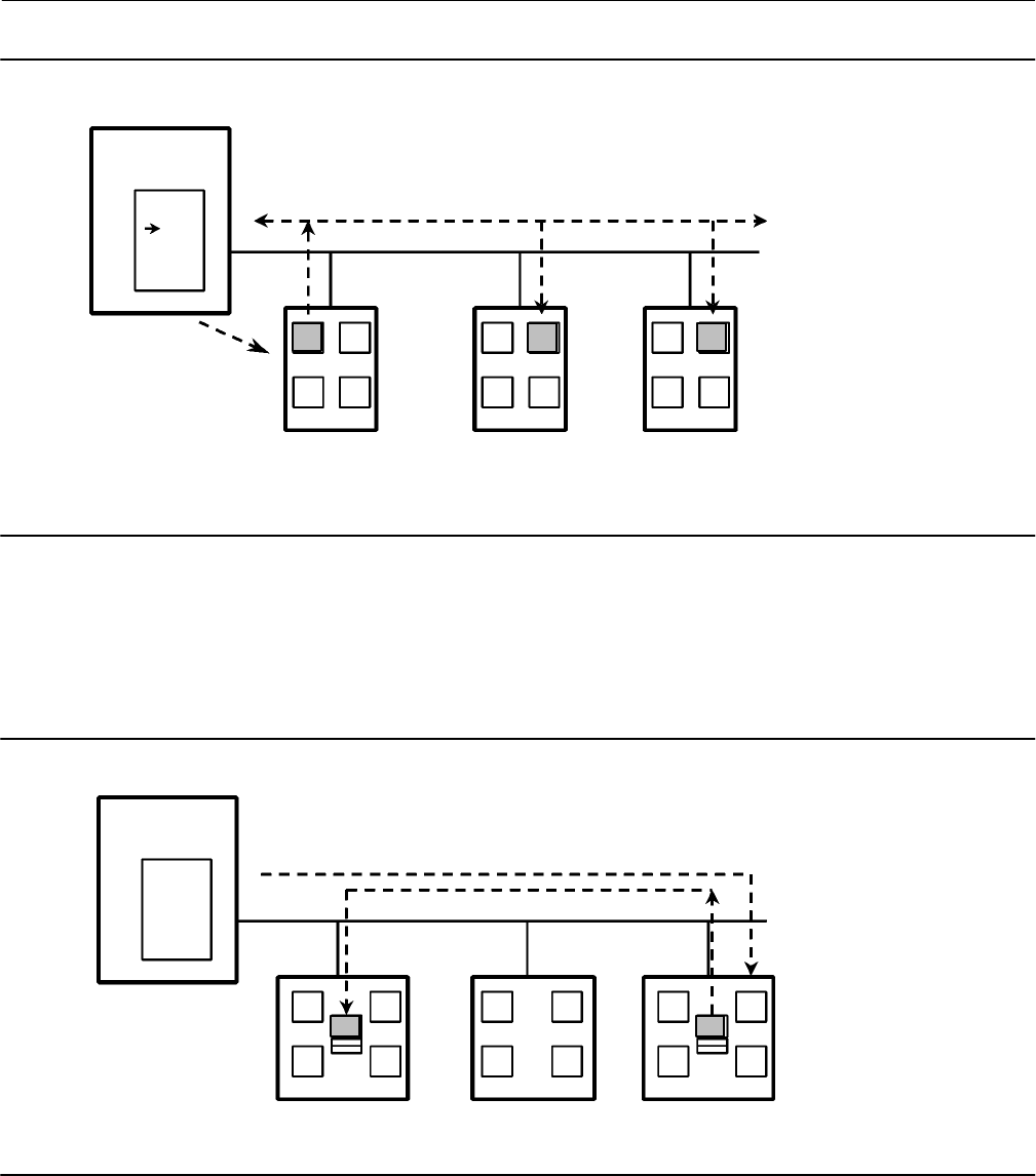
Instruction Manual
D103412X012
FOUNDATION fieldbus Communication
January 2015
271
Figure D‐4. Scheduled Data Transfer
B2713‐1
LAS
DT(A)
Device X Device Y Device Z
CD (X, A)
LAS=Link Active Scheduler
P=Publisher
S=Subscriber
CD=Compel Data
DT=Data Transfer Packet
Schedule
X
Y
Z
B
PPPSSS
CD
AAA
Host System
Unscheduled Transfers
Figure D‐5 diagrams an unscheduled transfer. Unscheduled transfers are used for things like user‐initiated changes,
including set point changes, mode changes, tuning changes, and upload/download. Unscheduled transfers use either
report distribution or client/server type of reporting for transferring data.
Figure D‐5. Unscheduled Data Transfer
B2714‐1
LAS
Device X Device Y Device Z
PT (Z)
LAS=Link Active Scheduler
P=Publisher
S=Subscriber
PT=Pass Token
M=Message
Schedule
X
Y
Z
B
PPPSS
S
CD
AAA
MM
Host System
All of the devices on the fieldbus are given a chance to send unscheduled messages between transmissions of
scheduled data. The LAS grants permission to a device to use the fieldbus by issuing a pass token (PT) message to the
device. When the device receives the PT, it is allowed to send messages until it has finished or until the “maximum
token hold time” has expired, whichever is the shorter time. The message may be sent to a single destination or to
multiple destinations.
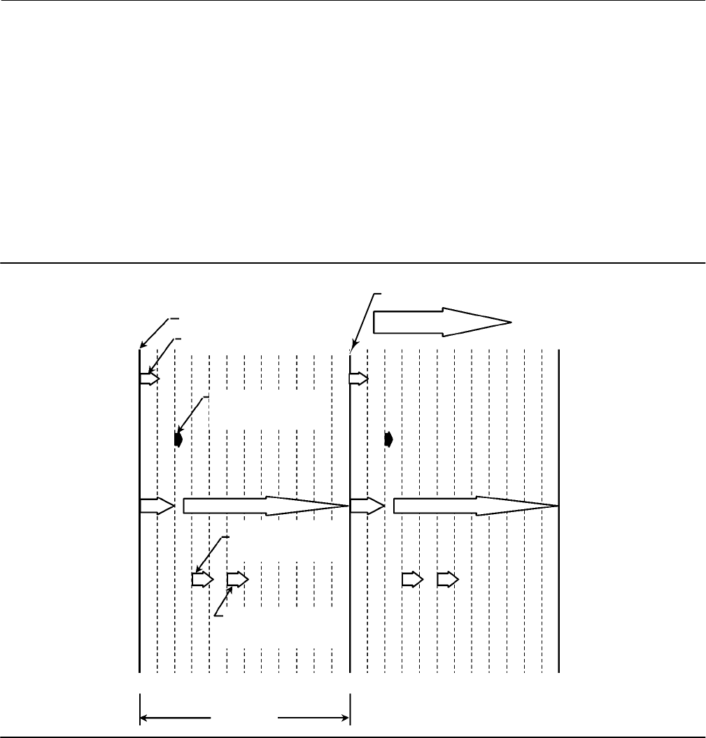
Instruction Manual
D103412X012
FOUNDATION fieldbus Communication
January 2015
272
Report Distribution: This type of communication is used to broadcast and multicast event and trend reports.
Client/Server: This type of communication is used for request/ response exchanges between pairs of devices, such
as a set point change. Like Report Distribution reporting, the transfers are queued, unscheduled, and prioritized.
Queued means the messages are sent and received in the order submitted for transmission, according to their
priority, without overwriting previous messages.
Function Block Scheduling
Figure D‐6 shows an example of a link schedule. A single iteration of the link‐wide schedule is called the macrocycle.
When the system is configured and the function blocks are linked, a master link‐wide schedule is created for the LAS.
Each device maintains its portion of the link‐wide schedule, known as the Function Block Schedule. The Function Block
Schedule indicates when the function blocks for the device are to be executed. The scheduled execution time for each
function block is represented as an offset from the beginning of the macrocycle start time.
Figure D‐6. Example Link Schedule Showing Scheduled and Unscheduled Communication
B2715‐1
Sequence Repeats
AI AI
AO AOPIDPID
Macrocycle Start Time
Offset from macrocycle
start time = 0 for AI Execution
Offset from macrocycle
start time = 20 for AI
Communication
Offset from macrocycle
start time = 30 for AI
Execution
Device 1
Scheduled
Communication
Unscheduled
Communication
Device 2
Macrocycle
0 20 40 60 80 100 120 20 40 60 80 100 120
Offset from macrocycle
start time = 50 for AO
Communication
Start of Next Macrocycle
To support synchronization of schedules, periodically Link Scheduling (LS) time is distributed. The beginning of the
macrocycle represents a common starting time for all Function Block schedules on a link and for the LAS link‐wide
schedule. This permits function block executions and their corresponding data transfers to be synchronized in time.
Network Management
Information for setting up network communications, including Virtual Communication Relationships (VCRs), host
timer recommendations, and other network parameters, can be found in the capabilities file (.cff) available from the
website www.FIELDVUE.com or from the Fieldbus Foundation website.

Instruction Manual
D103412X012
Device Description Installation
January 2015
273
Appendix E Device Description Installation10‐E‐E‐
Overview
Several support files are required for the DVC6200f digital valve controller. They are:
Device Description (DD) files—These files define the data interface to the digital valve controller (file extensions
.sym and .ffo).
Capabilities File—These files allow a host to configure the control system off‐line (e.g., without having a device
physically attached to the host) (file extension .cff).
DeltaV Registry File—This file is used by DeltaV to define the device interface (file extension .reg)
DeltaV fhx File—This file is used by DeltaV to define the device and the data interface to the device (file extension
.fhx).
DeltaV Windows Resource File—These files define the user interface for the device for DeltaV and include the
definitions for the transducer block interface and the resource block interface (file extension .dll).
The directory structure defined by the Fieldbus Foundation for device descriptions is as follows:
....\xxxxxx\yyyy\rrddcc.eee
where:
....\ is the path to the DD structure as implemented by the host system. This is typically defined as the base path
to the DD since access to the specific device DD is predefined from the base folder. For a DeltaV system, the
DDs are included with the support files and are located in a folder named “amsdevices.” For other hosts, the
Fieldbus Foundation defines a folder named “release” that is included with the CD‐ROM, however, you do not
need to retain this folder name.
xxxxxx is the 6‐digit hexadecimal equivalent of the manufacturer's identification number as defined by the Fieldbus
Foundation. Fisher Controls' ID number is 5100 (or in the folder format 005100). This number is also stored in
the instrument Resource Block in the parameter Mfg ID (parameter name MANUFAC_ID).
yyyy is the 4‐digit hexadecimal equivalent of the device type, as defined by the manufacturer. For example, the
device type for the DVC6200f digital valve controller is 4602. This number is stored in the instrument
Resource Block in the parameter Device Type (parameter name DEV_TYPE).
rr is the 2‐digit hexadecimal equivalent of the device revision, as defined by the manufacturer. It is stored in the
instrument Resource Block in the parameter Device Revision (parameter name DEV_REV).
dd is the 2‐digit hexadecimal equivalent of the device description (DD) revision that applies to the device, as
defined by the manufacturer. The host will always use the latest version of the DD that it finds for a particular
device revision. When part of the name of a capabilities file, this value is always the same as the value of the
DD_REV parameter stored in the Resource Block of the instrument. The value of the DD_REV parameter
represents the earliest version of the DD that is compatible with the device revision of the instrument.
cc is a 2‐digit hexadecimal equivalent for the capabilities files (.cff) revision, as defined by the manufacturer. The
latest revision of the capabilities files, for a particular device revision, is the file with the largest value for this
number.
eee is the file extension. At this time, five extensions exist for files, they are:
.sym—This extension denotes a device description (DD) symbol file as defined by the Fieldbus
Foundation.
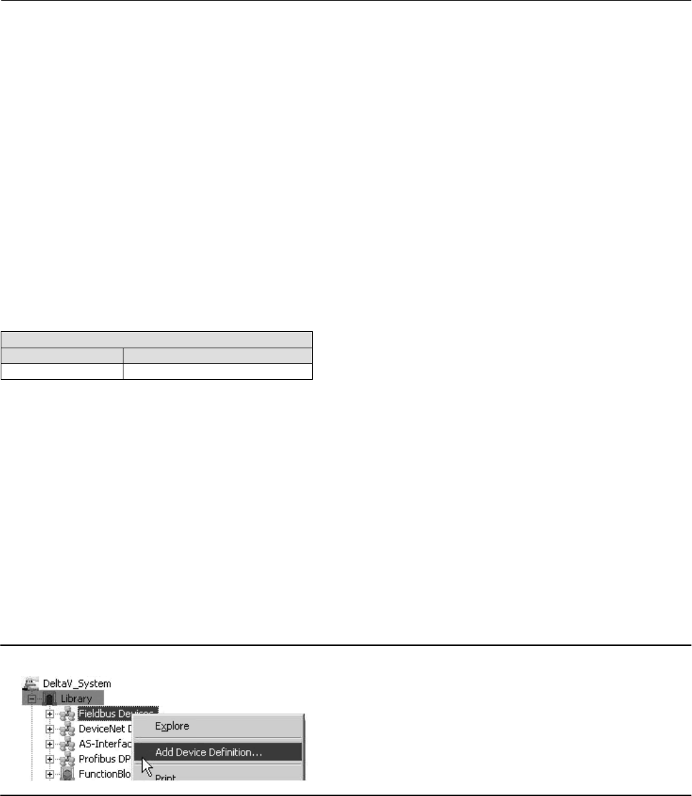
Instruction Manual
D103412X012
Device Description Installation
January 2015
274
.ffo—This extension denotes a complete, tokenized, device description for the instrument as defined by
the Fieldbus Foundation.
.cff—This extension denotes a capabilities file for the instrument as defined by the FOUNDATION Fieldbus
Common File Format specification.
.fhx—This extension denotes a DeltaV device definition file.
.dll—This extension denotes a windows resource file used by DeltaV.
.reg—This extension denotes a DeltaV registry file.
.alm—This extension denotes a DeltaV alarm file (DeltaV version 6 only).
Device Description and Methods
FOUNDATION fieldbus technology uses Device Descriptions (DD) and function blocks to achieve interoperability
between instruments and control systems or hosts from various manufacturers. The DD provides information to
describe the data interface to the device.
The following table describes the compatibility between the DVC6200f firmware revisions and DD revisions.
Device Description Compatibility
Firmware Revision DD Compatibility
2.0 2 and 3
For fieldbus devices, in addition to providing parameter definitions and other information required by the control
system to communicate with the fieldbus device, the DD may also include methods. Methods can be used for a variety
of functions including automatic calibration, setting protection, setting up the instrument, etc. These methods are a
predetermined sequence of steps for information required to setup, calibrate, and perform other functions on the
instrument. How the method prompts the user, and how messages appear is determined by the host system. For
information on using methods on the host system see the appropriate host system documentation.
Table E‐1 contains the methods available in the DVC6200f, the block it is found in, and the page number where it is
described.
Installing DD on a DeltaV ProfessionalPLUS Workstation
The following is general information that may apply when installing the DD on a DeltaV system during the Add Device
Definition procedure. This procedure is accessed from the DeltaV/Library, as shown in figure E‐1. For complete
information, refer to the DeltaV documentation.
Figure E‐1. Add Device Definition
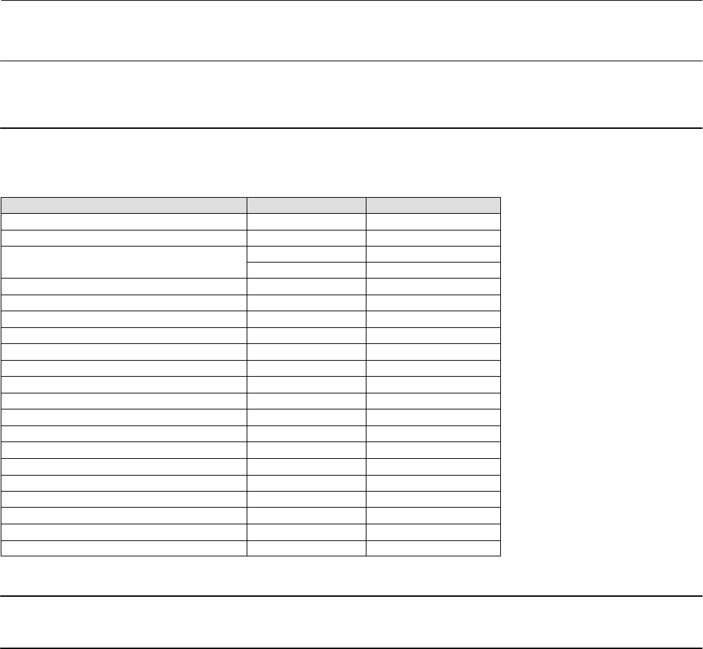
Instruction Manual
D103412X012
Device Description Installation
January 2015
275
Note
Before beginning the Add Device Definition procedure, it is recommended that the Add Device Utility be installed on DeltaV. This
may help prevent installation errors from occurring.
Table E‐1. Methods
Method Block Description Location
Auto Calibration Transducer page 190
Block Error Reporting Transducer page 62
Block Mode Transducer page 38
Resource page 21
Display DD Version Resource page 277
Instrument Alerts Transducer page 45
Manual Travel Calibration Transducer page 190
Output A Sensor Calibration Transducer page 193
Output B Sensor Calibration Transducer page 193
PlantWeb Alerts Transducer page 45
Relay Adjust Transducer page 191
Reset Options Resource page 197
Device Setup Transducer page 16
Stabilize/Optimize Transducer page 40
Stroke Valve Transducer page 204
Supply Sensor Calibration Transducer page 192
Define Custom Characteristic Transducer page 44
Travel Deviation Fallback Transducer page 43
Outblock Selection Transducer page 45
PlantWeb Alerts Set PV Status Transducer page 62
Performance Tuner Transducer page 20, 40
Note
Be sure to select the correct DD for the DeltaV revision being used. The resource files are different for each revision of DeltaV.
Device descriptions furnished by Fisher contain only those files applicable to Fisher. All the files are located in the
manufacturer ID Folder (005100 for xxxxxx in directory structure above). A readme file is included at the top level.
Read this file for any additional information regarding DD installation.
Device descriptions furnished by the Fieldbus Foundation (on CD‐ROM or diskette) contain the files for each
registered manufacturer and their associated device(s). It is placed on the media starting with the release folder,
which then contains a folder (xxxxxx) for each manufacturer as defined above. For Fisher this folder is 005100. A
readme file may be included at the top level. Read this file for any additional information regarding the DD.
For the DVC6200f—The device type parameter for this unit is 4602. This device includes the AO, PID, ISEL, OS, AI,
MAI, DO and DI function blocks. From DeltaV Explorer, select the amsdevices\005100\4602 folder (refer to
figure E‐2).
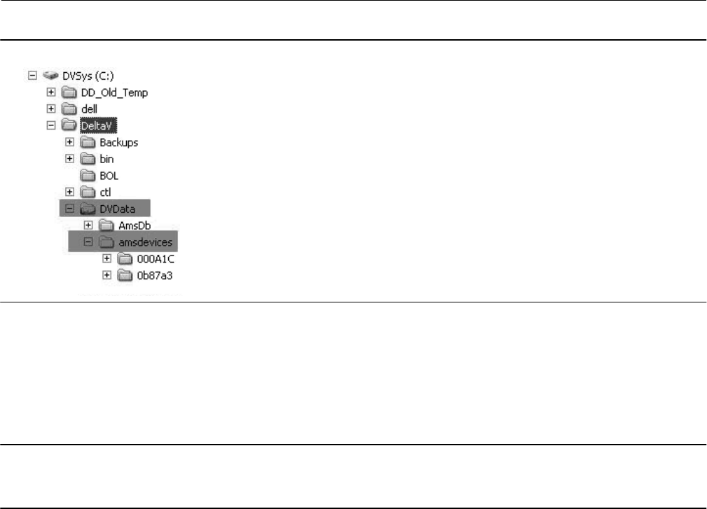
Instruction Manual
D103412X012
Device Description Installation
January 2015
276
Figure E‐2. amsdevices folder
The most recent device description for Fisher devices can be downloaded from the internet at www.FIELDVUE.com.
If you are downloading from the internet, the file on the website will be compressed (zipped) and must be
decompressed (unzipped) before proceeding. Refer to the website download and installation procedures for setting
up the DD on your system. Note the folder where the decompressed files are placed. This information will be
required later in the installation procedure.
Note
Record any warning/error messages from the message window in DeltaV Explorer so that it can be communicated to the DeltaV
Technical Support Group.
Installing DDs on Other Fieldbus Host Systems
The following is a generic procedure for installing the device descriptions on a host system. Refer to your host system
documentation for specific information. In general the following may apply:
Device descriptions furnished by Fisher contain only those files applicable to Fisher. All the files are located in the
manufacturer ID Folder (005100 for xxxxxx in directory structure above). A readme file is included at the top level.
Read this file for any additional information regarding DD installation.
Device descriptions furnished by the Fieldbus Foundation (on CD‐ROM or diskette) contain the files for each
registered manufacturer and their associated device(s). It is placed on the media starting with the release folder,
which then contains a folder (xxxxxx) for each manufacturer as defined above. For Fisher this folder is 005100. A
readme file may be included at the top level. Read this file for any additional information regarding the DD.
For the DVC6200f Digital Valve Controller—The device type parameter for this unit is 4602. This device includes the
AO, PID, ISEL, OS, AI, MAI, DO and DI function blocks. From Windows Explorer, select the release\005100\4602
folder.
The most recent device description for Fisher devices can be downloaded from the internet at www.fisher.com. If
you are downloading from the internet, the file on the website will be compressed (zipped) and must be
decompressed (unzipped) before proceeding. Refer to the website download and installation procedures for setting

Instruction Manual
D103412X012
Device Description Installation
January 2015
277
up the DD on your system. Note the folder where the decompressed files are placed. This information will be
required later in the installation procedure.
Note
This procedure will install the necessary Device Description files (*.ffo and *.sym), and Capabilities file (*.cff) for the device.
1. Locate or create the folder on the host system to contain all the DD and capabilities files.
If you are creating a folder, you can name this new folder whatever you would like and it can have any path you define.
For this installation procedure, this folder will be referred to as the base folder.
2. On the CD‐ROM or in the website download files, locate the folder with the new support files. This folder is called
\RELEASE.
3. Open this folder and select the folder named 005100.
4. Copy the 005100 folder (and all its subfolders) from the CD‐ROM or website download location to the base folder.
If this is an update (the folders already exist), the system informs you that the folders already exist and asks if they
should be replaced. Answer Yes or OK so the folders are properly updated.
5. The new support files are now installed. You may have to restart applications and drivers in order for the new files to
become active.
DD installation is complete. Consult the system documentation for commissioning new devices or updating existing
devices.
Displaying the Device Description Version
You can use the DD In Use method to display version information for the device descriptions installed on the system.
The DD in Use method is included with the device description (DD) software. For information on using methods, see
the host system documentation.
DD in Use displays the version number displayed in the format: device type.device revision.DD revision. The Min
Compatible DD revision displayed is the latest device description revision that is compatible with the displayed device
revision.
This method is available via the resource block.

Instruction Manual
D103412X012
Device Description Installation
January 2015
278

Instruction Manual
D103412X012
Operating with a DeltaV System
January 2015
279
Appendix F Operating with a DeltaV SystemF‐F‐
Process Systems DeltaV System
Getting Started with DeltaV Host Systems
Appropriate Device Descriptions (DDs) installed. See the Device Description Compatibility table on
page 274. For DD installation information see Appendix E.
Digital valve controller correctly mounted on actuator. For mounting information see the
Installation section of this manual and the instructions included with the mounting kit.
Utilities connected. For information on making pneumatic and electrical connections, see the
Installation section of this manual. For information on applying power to the segment, see DeltaV
books online.
Instrument in standby. For information on placing the instrument in standby, see DeltaV books
online.
Perform the initial setup. See the Basic Setup section of this manual. If the valve is shipped from the
factory mounted on an actuator, perform basic setup only to verify setup is correct and valve
operation is satisfactory.
Device Commissioned. For information on commissioning a device, see DeltaV books online.
Additional configuration required, such as setting alarms, cutoffs, and other resource block and
transducer block parameters. See the Detailed Setup section of this manual.
Control strategy defined. For information on defining a control strategy, see DeltaV books online.
Associate I/O with device. See DeltaV books online.
Download device. See DeltaV books online.

Instruction Manual
D103412X012
Operating with a DeltaV System
January 2015
280
Table F‐1. Transducer Block (TB) Parameters - Configuration Index
Parameter Label Path to Parameter
Actual Travel TB > Configure/Setup > Detailed Setup > Valve and Actuator > Valve > Actual Travel
Actuator Fail Action TB > Configure/Setup > Detailed Setup > Valve and Actuator > Actuator > Actuator Fail Action
Actuator Manufacturer ID TB > Configure/Setup > Detailed Setup > Valve and Actuator > Actuator > Actuator Manufacturer ID
Actuator Model Number TB > Configure/Setup > Detailed Setup > Valve and Actuator > Actuator > Actuator Model Number
Actuator Serial Number TB > Configure/Setup > Detailed Setup > Valve and Actuator > Actuator > Actuator Serial Number
Actuator Size TB > Configure/Setup > Detailed Setup > Valve and Actuator > Actuator > Actuator Size
Actuator Style TB > Configure/Setup > Detailed Setup > Valve and Actuator > Actuator > Actuator Style
Air TB > Configure/Setup > Detailed Setup > Valve and Actuator > Actuator > Air
Alert Conditions TB > Device Diagnostics > Alert Conditions
Alert Key TB > Configure/Setup > Detailed Setup > Alerts > Configuration > Alert Key
Area Units TB > Configure/Setup > Detailed Setup > Instrument > Units: Area Units
Block Configuration Error TB > Device Diagnostics > Status > Transducer Block Error: Block Configuration Error
Blocks Set to Default Alert TB > Configure/Setup > Detailed Setup > Alerts > Configuration > Blocks Set to Default: Block Set to Default Alert
Blocks Set to Default Alert Enable TB > Configure/Setup > Detailed Setup > Alerts > Configuration > Blocks Set to Default: Block Set to Default Alert Enable
Calibration Date TB > Configure/Setup > Detailed Setup > Instrument > Calibration: Calibration Date
Calibration Location TB > Configure/Setup > Detailed Setup > Instrument > Calibration: Calibration Location
Calibration Person TB > Configure/Setup > Detailed Setup > Instrument > Calibration: Calibration Person
Cycle Count TB > Configure/Setup > Detailed Setup > Alerts > Travel History > Cycle Counter:Cycle Count
TB > Device Variables > Overview > Cycle Count
Cycle Count Alert TB > Configure/Setup > Detailed Setup > Alerts > Travel History > Cycle Counter: Cycle Count Alert
Cycle Count Alert Enable TB > Configure/Setup > Detailed Setup > Alerts > Travel History > Cycle Counter: Cycle Count Alert Enable
Cycle Count Alert Point TB > Configure/Setup > Detailed Setup > Alerts > Travel History > Cycle Counter Cycle Count Alert Point
Cycle Count Deadband TB > Configure/Setup > Detailed Setup > Alerts > Travel History > Cycle Counter: Cycle Count Deadband
Device Needs Maintenance Now TB > Device Diagnostics > Status > Transducer Block Error: Device Needs Maintenance Now
Drive Current TB > Configure/Setup > Detailed Setup > Alerts > Electronic > Drive Current: Drive Current
Drive Current Alert TB > Device Diagnostics > Status > Self Test Status: Drive Current Alert
TB > Configure/Setup > Detailed Setup > Alerts > Electronic > Drive Current: Drive Current Alert
Drive Current Alert Enable TB > Configure/Setup > Detailed Setup > Alerts > Electronic > Drive Current: Drive Current Alert Enable
Drive Current Alert Point TB > Configure/Setup > Detailed Setup > Alerts > Electronic > Drive Current: Drive Current Alert Point
Drive Current Alert Time TB > Configure/Setup > Detailed Setup > Alerts > Electronic > Drive Current: Drive Current Alert Time
Drive Current Manual Recovery TB > Configure/Setup > Detailed Setup > Alerts > Electronic > Drive Current: Drive Current Manual Recovery
Drive Current Shutdown TB > Configure/Setup > Detailed Setup > Alerts > Electronic > Drive Current: Drive Current Shutdown
Drive Signal TB > Configure/Setup > Detailed Setup > Alerts > Electronic > Drive Signal: Drive Signal
TB > Device Variables > Overview > Drive Signal
Drive Signal Alert TB > Configure/Setup > Detailed Setup > Alerts > Electronic > Drive Signal: Drive Signal Alert
Drive Signal Alert Enable TB > Configure/Setup > Detailed Setup > Alerts > Electronic > Drive Signal: Drive Signal Alert Enable
Effective Area TB > Configure/Setup > Detailed Setup > Valve and Actuator > Actuator > Effective Area
Feedback Connection TB > Configure/Setup > Detailed Setup > Valve and Actuator > Actuator > Feedback Connection
Flow Direction TB > Configure/Setup > Detailed Setup > Valve and Actuator > Trim > Flow Direction
Flow Tends To TB > Configure/Setup > Detailed Setup > Valve and Actuator > Trim > Flow Tends To
I/O Processor Alert TB > Configure/Setup > Detailed Setup > Alerts > Electronic > Processor Impaired: I/O Processor Alert
I/O Processor Alert Enable TB > Configure/Setup > Detailed Setup > Alerts > Electronic > Processor Impaired: I/O Processor Alert Enable
I/O Processor Manual Recovery TB > Configure/Setup > Detailed Setup > Alerts > Electronic > Processor Impaired: I/O Processor Man Recovery
I/O Processor Shutdown TB > Configure/Setup > Detailed Setup > Alerts > Electronic > Processor Impaired: I/O Processor Shutdown
Inlet Pressure TB > Configure/Setup > Detailed Setup > Valve and Actuator > Valve > Inlet Pressure
Input Characterization TB > Configure/Setup > Detailed Setup > Response Control > Input Characterization > Input Characterization
TB > Device Variables > Overview > Input Characterization
Integrator Limited Hi TB > Device Diagnostics > Status > Self Test Status: Integrator Limited Hi
Integrator Limited Lo TB > Device Diagnostics > Status > Self Test Status: Integrator Limited Lo
Integrator Suspended TB > Device Diagnostics > Status > Self Test Status: Integrator Suspended
IOP Failure TB > Device Diagnostics > Status > Self Test Status: IOP Failure
Last Valid Point TB > Configure/Setup > Detailed Setup > Response Control > Input Characterization > Last Valid Point
Leak Class TB > Configure/Setup > Detailed Setup > Valve and Actuator > Trim > Leak Class
Length Units TB > Configure/Setup > Detailed Setup > Instrument > Units: Length Units
-Continued-

Instruction Manual
D103412X012
Operating with a DeltaV System
January 2015
281
Table F‐1. Transducer Block (TB) Parameters - Configuration Index (Continued)
Path to ParameterParameter Label
Lever Style TB > Configure/Setup > Detailed Setup > Valve and Actuator > Actuator > Lever Style
Lost Static Data TB > Device Diagnostics > Status > Transducer Block Error: Lost Static Data
Lower Bench Set TB > Configure/Setup > Detailed Setup > Valve and Actuator > Actuator > Lower Bench Set
MAI Channel 1 TB > Configure/Setup > Detailed Setup > MAI Channel Map > MAI Channel 1
MAI Channel 2 TB > Configure/Setup > Detailed Setup > MAI Channel Map > MAI Channel 2
MAI Channel 3 TB > Configure/Setup > Detailed Setup > MAI Channel Map > MAI Channel 3
MAI Channel 4 TB > Configure/Setup > Detailed Setup > MAI Channel Map > MAI Channel 4
MAI Channel 5 TB > Configure/Setup > Detailed Setup > MAI Channel Map > MAI Channel 5
MAI Channel 6 TB > Configure/Setup > Detailed Setup > MAI Channel Map > MAI Channel 6
MAI Channel 7 TB > Configure/Setup > Detailed Setup > MAI Channel Map > MAI Channel 7
MAI Channel 8 TB > Configure/Setup > Detailed Setup > MAI Channel Map > MAI Channel 8
Maximum Supp Pressure TB > Configure/Setup > Detailed Setup > Instrument > Application: Max Supp Pressure
MLFB Error TB > Device Diagnostics > Status > Self Test Status: MLFB Error
Moment Arm Length TB > Configure/Setup > Detailed Setup > Valve and Actuator > Actuator > Moment Arm
Nominal Supply Pressure TB > Configure/Setup > Detailed Setup > Valve and Actuator > Actuator > Nominal Supply Pressure
Out of Service TB > Device Diagnostics > Status > Transducer Block Error: Out of Service
Outlet Pressure TB > Configure/Setup > Detailed Setup > Valve and Actuator > Valve > Outlet Pressure
Output Block Timeout TB > Configure/Setup > Detailed Setup > Alerts > Configuration > Output Block Timeout: Output Blk Timeout
Output Block Timeout Alert TB > Configure/Setup > Detailed Setup > Alerts > Configuration > Output Block Timeout: Output Block Timeout Alert
Output Block Timeout Alert Enable TB > Configure/Setup > Detailed Setup > Alerts > Configuration > Output Block Timeout: Output Block Timeout Alert Enable
Output Block Timeout Manual
Recovery TB > Configure/Setup > Detailed Setup > Alerts > Configuration > Output Block Timeout: Output Block Timeout Manual Recovery
Output Block Timeout Shutdown TB > Configure/Setup > Detailed Setup > Alerts > Configuration > Output Block Timeout: Output Block Timeout Shutdown
Packing Type TB > Configure/Setup > Detailed Setup > Valve and Actuator > Valve > Packing Type
PD Inside Status TB > Configure/Setup > Detailed Setup > Alerts > Performance > PD Inside Status
PD Inside Status TB > Device Variables > Overview > PD Inside Status
PD Run TB > Configure/Setup > Detailed Setup > Alerts > Performance > PD Run
Performance Critical Alert TB > Configure/Setup > Detailed Setup > Alerts > Performance > Performance Critical: Performance Critical Alert
Performance Critical Alert Enable TB > Configure/Setup > Detailed Setup > Alerts > Performance > Performance Critical: Performance Critical Alert Enable
Performance Information Alert TB > Configure/Setup > Detailed Setup > Alerts > Performance > Performance Information: Performance Information Alert
Performance Information Alert
Enable TB > Configure/Setup > Detailed Setup > Alerts > Performance > Performance Information: Performance Information Alert Enable
Performance Reduced Alert TB > Configure/Setup > Detailed Setup > Alerts > Performance > Performance Reduced: Performance Reduced Alert
Performance Reduced Alert Enable TB > Configure/Setup > Detailed Setup > Alerts > Performance > Performance Reduced: Performance Reduced Alert Enable
Performance Tuner(1) TB > Configure/Setup > Basic Setup > Performance Tuner
Port Diameter TB > Configure/Setup > Detailed Setup > Valve and Actuator > Trim > Port Diameter
Port Type TB > Configure/Setup > Detailed Setup > Valve and Actuator > Trim > Port Type
Pressure A Sensor Alert TB > Configure/Setup > Detailed Setup > Alerts > Sensor > Pressure Sensors: Pressure A Sensor Alert
Pressure A Sensor Alert Enable TB > Configure/Setup > Detailed Setup > Alerts > Sensor > Pressure Sensors: Pressure A Sensor Alert Enable
Pressure A Sensor Manual Recovery TB > Configure/Setup > Detailed Setup > Alerts > Sensor > Pressure Sensors: Pressure A Sensor Manual Recovery
Pressure A Sensor Shutdown TB > Configure/Setup > Detailed Setup > Alerts > Sensor > Pressure Sensors: Pressure A Sensor Shutdown
Pressure B Sensor Alert TB > Configure/Setup > Detailed Setup > Alerts > Sensor > Pressure Sensors: Pressure B Sensor Alert
Pressure B Sensor Alert Enable TB > Configure/Setup > Detailed Setup > Alerts > Sensor > Pressure Sensors: Pressure B Sensor Alert Enable
Pressure Cutoff Close TB > Configure/Setup > Detailed Setup > Response Control > Travel / Pressure Control > Pressure Control: Pressure Cutoff Close
Pressure Cutoff Open TB > Configure/Setup > Detailed Setup > Response Control > Travel / Pressure Control > Pressure Control: Pressure Cutoff Open
Pressure Integral Deadzone TB > Configure/Setup > Detailed Setup > Response Control > Pressure Tuning: Pressure Integral Deadzone
Pressure Integral Gain TB > Configure/Setup > Detailed Setup > Response Control > Pressure Tuning: Pressure Integral Gain
Pressure Integral Limit Hi TB > Configure/Setup > Detailed Setup > Response Control > Pressure Tuning: Pressure Integral Limit Hi
Pressure Integral Limit Lo TB > Configure/Setup > Detailed Setup > Response Control > Pressure Tuning: Pressure Integral Limit Lo
Pressure MLFB Gain TB > Configure/Setup > Detailed Setup > Response Control > Pressure Tuning: Pressure MLFB Gain
Pressure Proportional Gain TB > Configure/Setup > Detailed Setup > Response Control > Pressure Tuning: Pressure Prop Gain
Pressure Range Hi TB > Configure/Setup > Detailed Setup > Response Control > Travel / Pressure Control > Pressure Control: Pressure Range Hi
Pressure Range Lo TB > Configure/Setup > Detailed Setup > Response Control > Travel / Pressure Control > Pressure Control: Pressure Range Lo
Pressure Tuning Set TB > Configure/Setup > Detailed Setup > Response Control > Pressure Tuning: Pressure Tuning Set
-Continued-

Instruction Manual
D103412X012
Operating with a DeltaV System
January 2015
282
Table F‐1. Transducer Block (TB) Parameters - Configuration Index (Continued)
Path to ParameterParameter Label
Pressure A TB > Device Variables > Overview > Pressures: Pressure A
Pressure A Sensor Failure TB > Device Diagnostics > Status > Self Test Status: Pressure A Sensor Failure
Pressure B TB > Device Variables > Overview > Pressures: Pressure B
Pressure B Sensor Failure TB > Device Diagnostics > Status > Self Test Status: Pressure B Sensor Failure
Pressure Differential TB > Device Variables > Overview > Pressures: Pressure Diff
Pressure Fallback Alert TB > Configure/Setup > Detailed Setup > Alerts > Sensor > Pressure Fallback: Pressure Fallback Alert
Pressure Fallback Alert Enable TB > Configure/Setup > Detailed Setup > Alerts > Sensor > Pressure Fallback: Pressure Fallback Alert Enable
Pressure Units TB > Configure/Setup > Detailed Setup > Instrument > Units: Pressure Units
Processor Alert TB > Configure/Setup > Detailed Setup > Alerts > Electronic > Processor Impaired: Processor Alert
Processor Alert Enable TB > Configure/Setup > Detailed Setup > Alerts > Electronic > Processor Impaired: Processor Alert Enable
Program Memory Alert Enable TB > Configure/Setup > Detailed Setup > Alerts > Electronic > Processor Impaired: Program Memory Alert Enable
Program Memory Manual Recovery TB > Configure/Setup > Detailed Setup > Alerts > Electronic > Processor Impaired: Program Memory Manual Recovery
Program Memory Shutdown TB > Configure/Setup > Detailed Setup > Alerts > Electronic > Processor Impaired: Program Memory Shutdown
Program Memory Alert TB > Configure/Setup > Detailed Setup > Alerts > Electronic > Processor Impaired: Program Memory Alert
Protection TB > Device Variables > Overview > Protection
Proximity Hi Alert TB > Configure/Setup > Detailed Setup > Alerts > Proximity > Proximity: Proximity Hi Alert
Proximity Hi Alert Enable TB > Configure/Setup > Detailed Setup > Alerts > Proximity > Proximity: Proximity Hi Alert Enable
Proximity Hi Hi Alert TB > Configure/Setup > Detailed Setup > Alerts > Proximity > Proximity: Proximity Hi Hi Alert
Proximity Hi Hi Alert Enable TB > Configure/Setup > Detailed Setup > Alerts > Proximity > Proximity: Proximity Hi Hi Alert Enable
Proximity Lo Alert TB > Configure/Setup > Detailed Setup > Alerts > Proximity > Proximity: Proximity Lo Alert
Proximity Lo Alert Enable TB > Configure/Setup > Detailed Setup > Alerts > Proximity > Proximity: Proximity Lo Alert Enable
Proximity Lo Lo Alert TB > Configure/Setup > Detailed Setup > Alerts > Proximity > Proximity: Proximity Lo Lo Alert
Proximity Lo Lo Alert Enable TB > Configure/Setup > Detailed Setup > Alerts > Proximity > Proximity: Proximity Lo Lo Alert Enable
Push Down To TB > Configure/Setup > Detailed Setup > Valve and Actuator > Trim > Push Down To
Simulate PlantWeb Alerts TB > Configure/Setup > Detailed Setup > Alert Handling > Simulate PlantWeb Alerts
Rated Travel TB > Configure/Setup > Detailed Setup > Valve and Actuator > Valve > Rated Travel
Relay Type TB > Configure/Setup > Detailed Setup > Instrument > Application: Relay Type
Seat Type TB > Configure/Setup > Detailed Setup > Valve and Actuator > Trim > Seat Type
Setpoint TB > Device Variables > Overview > AO Control‐Pre‐Characterization: Setpoint
Setpoint Status TB > Device Variables > Overview > AO Control‐Pre‐Characterization: Setpoint Status
Setpoint(D) TB > Device Variables > Overview > DO Control: Setpoint(D)
Shaft Stem Diameter TB > Configure/Setup > Detailed Setup > Valve and Actuator > Valve > Shaft Stem Dia
Simulate Active TB > Device Diagnostics > Status > Transducer Block Error: Simulate Active
Simulate Jumper ON TB > Device Diagnostics > Status > Self Test Status: Simulate Jumper ON
Spring Rate TB > Configure/Setup > Detailed Setup > Valve and Actuator > Actuator > Spring Rate
Spring Rate Units TB > Configure/Setup > Detailed Setup > Instrument > Units: Spring Rate Units
Static Memory Alert TB > Configure/Setup > Detailed Setup > Alerts > Electronic > Processor Impaired: Static Memory Alert
Static Memory Alert Enable TB > Configure/Setup > Detailed Setup > Alerts > Electronic > Processor Impaired: Static Memory Alert Enable
Static Memory Manual Recovery TB > Configure/Setup > Detailed Setup > Alerts > Electronic > Processor Impaired: Static Memory Manual Recovery
Static Memory Shutdown TB > Configure/Setup > Detailed Setup > Alerts > Electronic > Processor Impaired: Static Memory Shutdown
Stroke Time Close TB > Configure/Setup > Detailed Setup > Valve and Actuator > Reference > Stroke Time Close
Stroke Time Open TB > Configure/Setup > Detailed Setup > Valve and Actuator > Reference > Stroke Time Open
Supply Pressure Maximum TB > Device Diagnostics > Device Record > Supp Pressure Max
Supply Pressure Maximum Time TB > Device Diagnostics > Device Record > Supp Pressure Maximum Time
Supp Pressure Minimum TB > Device Diagnostics > Device Record > Supp Pressure Minimum
Supp Pressure Minimum Time TB > Device Diagnostics > Device Record > Supp Pressure Minimum Time
Supply Pressure TB > Configure/Setup > Detailed Setup > Alerts > Environment > Supply Pressure: Supply Pressure
Supply Pressure TB > Device Variables > Overview > Pressures: Supply Pressure
Supply Pressure Hi Alert TB > Configure/Setup > Detailed Setup > Alerts > Environment > Supply Pressure: Supply Pressure Hi Alert
Supply Pressure Hi Alert Enable TB > Configure/Setup > Detailed Setup > Alerts > Environment > Supply Pressure: Pressure Hi Alert Enable
Supply Pressure Hi Alert Point TB > Configure/Setup > Detailed Setup > Alerts > Environment > Supply Pressure: Supply Pressure Hi Alert Point
Supply Pressure Lo Alert TB > Configure/Setup > Detailed Setup > Alerts > Environment > Supply Pressure: Supply Pressure Lo Alert
Supply Pressure Lo Alert Enable TB > Configure/Setup > Detailed Setup > Alerts > Environment > Supply Pressure: Supply Pressure Lo Alert Enable
Supply Pressure Lo Alert Point TB > Configure/Setup > Detailed Setup > Alerts > Environment > Supply Pressure: Supply Pressure Lo Alert Point
-Continued-

Instruction Manual
D103412X012
Operating with a DeltaV System
January 2015
283
Table F‐1. Transducer Block (TB) Parameters - Configuration Index (Continued)
Path to ParameterParameter Label
Supply Pressure Sensor Alert TB > Configure/Setup > Detailed Setup > Alerts > Sensor > Pressure Sensors: Supply Pressure Sensor Alert
Supply Pressure Sensor Alert Enable TB > Configure/Setup > Detailed Setup > Alerts > Sensor > Pressure Sensors: Supply Pressure Sensor Alert Enable
Supply Sensor Failure TB > Device Diagnostics > Status > Self Test Status: Supply Sensor Failure
Tag Description TB > Configure/Setup > Detailed Setup > Instrument > Tag Description
Temperature Hi Alert Point TB > Configure/Setup > Detailed Setup > Alerts > Environment > Temperature Limit: Temperature Hi Alert Point
Temperature Lo Alert Point TB > Configure/Setup > Detailed Setup > Alerts > Environment > Temperature Limit: Temperature Lo Alert Point
Temperature Maximum TB > Device Diagnostics > Device Record > Temperature Maximum
Temperature Maximum Time TB > Device Diagnostics > Device Record > Temperature Maximum Time
Temperature Minimum TB > Device Diagnostics > Device Record > Temperature Minimum
Temperature Minimum Time TB > Device Diagnostics > Device Record > Temperature Minimum Time
Temperature TB > Configure/Setup > Detailed Setup > Alerts > Environment > Temperature Limit: Temperature
TB > Device Variables > Overview > Temperature
Temperature Hi Alert TB > Configure/Setup > Detailed Setup > Alerts > Environment > Temperature Limit: Temperature Hi Alert
Temperature Hi Alert Enable TB > Configure/Setup > Detailed Setup > Alerts > Environment > Temperature Limit: Temperature Hi Alert Enable
Temperature Lo Alert TB > Configure/Setup > Detailed Setup > Alerts > Environment > Temperature Limit: Temperature Lo Alert
Temperature Lo Alert Enable TB > Configure/Setup > Detailed Setup > Alerts > Environment > Temperature Limit: Temperature Lo Alert Enable
Temperature Lo Alert Point TB > Configure/Setup > Detailed Setup > Alerts > Environment > Temperature Limit: Temperature Lo Alert Point
Temperature Sensor Alert TB > Configure/Setup > Detailed Setup > Alerts > Sensor > Temperature Sensor: Temperature Sensor Alert
Temperature Sensor Alert Enable TB > Configure/Setup > Detailed Setup > Alerts > Sensor > Temperature Sensor: Temperature Sensor Alert Enable
Temperature Units TB > Configure/Setup > Detailed Setup > Instrument > Units: Temperature Units
Travel
TB > Configure/Setup > Detailed Setup > Alerts > Proximity > Travel
TB > Configure/Setup > Detailed Setup > Alerts > Travel > Travel
TB > Device Variables > Overview > AO Control ‐ Post‐Characterization: Travel
Travel(D) TB > Device Variables > Overview > DO Control: Travel(D)
Travel(DeChar) TB > Device Variables > Overview > AO Control ‐ Pre‐Characterization: Travel(DeChar)
Travel Status TB > Device Variables > Overview > AO Control ‐ Post‐Characterization: Travel Status
Trend TB > Device Diagnostics > Trend
Trim Style 1 TB > Configure/Setup > Detailed Setup > Valve and Actuator > Reference > Trim Style 1
Trim Style 2 TB > Configure/Setup > Detailed Setup > Valve and Actuator > Reference > Trim Style 2
Travel Accumulator TB > Configure/Setup > Detailed Setup > Alerts > Travel History > Travel Accumulator: Travel Accumulator
TB > Device Variables > Overview > Travel Accumulator
Travel Accumulator Alert TB > Configure/Setup > Detailed Setup > Alerts > Travel History > Travel Accumulator: Travel Accumulator Alert
Travel Accumulator Alert Enable TB > Configure/Setup > Detailed Setup > Alerts > Travel History > Travel Accumulator: Travel Accumulator Alert Enable
Travel Accumulator Alert Point TB > Configure/Setup > Detailed Setup > Alerts > Travel History > Travel Accumulator: Travel Accumulator Alert Point
Travel Accumulator Deadband TB > Configure/Setup > Detailed Setup > Alerts > Travel History > Travel Accumulator: Travel Accumulator Deadband
Travel Closed Alert TB > Configure/Setup > Detailed Setup > Alerts > Proximity > Travel Closed: Travel Closed Alert
Travel Closed Alert Enable TB > Configure/Setup > Detailed Setup > Alerts > Proximity > Travel Closed: Travel Closed Alert Enable
Travel Closed Alert Point TB > Configure/Setup > Detailed Setup > Alerts > Proximity > Travel Closed: Travel Closed Alert Point
Travel Closed Deadband TB > Configure/Setup > Detailed Setup > Alerts > Proximity > Travel Closed: Travel Closed Deadband
Travel Count TB > Device Variables > Overview > Travel Count
Travel Cutoff Hi TB > Configure/Setup > Detailed Setup > Response Control > Travel / Pressure Control > Travel Control: Travel Cutoff Hi
Travel Cutoff Lo TB > Configure/Setup > Detailed Setup > Response Control > Travel / Pressure Control > Travel Control: Travel Cutoff Lo
Travel Deviation Alert Point TB > Configure/Setup > Detailed Setup > Alerts > Travel > Travel Deviation: Travel Deviation Alert Point
Travel Deviation Deadband TB > Configure/Setup > Detailed Setup > Alerts > Travel: Travel Deviation Deadband
Travel Deviation Time TB > Configure/Setup > Detailed Setup > Alerts > Travel: Travel Deviation Time
Travel Deviation Alert TB > Configure/Setup > Detailed Setup > Alerts > Travel > Travel Deviation: Travel Deviation Alert
Travel Deviation Alert Enable TB > Configure/Setup > Detailed Setup > Alerts > Travel > Travel Deviation: Travel Deviation Alert Enable
Travel Integral Deadzone TB > Configure/Setup > Detailed Setup > Response Control > Travel Tuning: Travel Integral Deadzone
Travel Integral Enable TB > Configure/Setup > Detailed Setup > Response Control > Travel Tuning: Travel Integral Enable
Travel Integral Limit Hi TB > Configure/Setup > Detailed Setup > Response Control > Travel Tuning: Travel Integral Limit Hi
Travel Integral Limit Lo TB > Configure/Setup > Detailed Setup > Response Control > Travel Tuning: Travel Integral Limit Lo
Travel Integral Gain TB > Configure/Setup > Detailed Setup > Response Control > Travel Tuning: Travel Integral Gain
Travel Limit Hi Alert TB > Configure/Setup > Detailed Setup > Alerts > Travel > Travel Limit Hi/Lo: Travel Limit Hi Alert
Travel Limit Hi Alert Enable TB > Configure/Setup > Detailed Setup > Alerts > Travel > Travel Limit Hi/Lo: Travel Limit Hi Alert Enable
-Continued-

Instruction Manual
D103412X012
Operating with a DeltaV System
January 2015
284
Table F‐1. Transducer Block (TB) Parameters - Configuration Index (Continued)
Path to ParameterParameter Label
Travel Hi Alert Point TB > Configure/Setup > Detailed Setup > Alerts > Travel > Travel Limit Hi/Lo: Travel Hi Alert Point
Travel Hi Deadband TB > Configure/Setup > Detailed Setup > Alerts > Travel > Travel Limit Hi/Lo: Travel Hi Deadband
Travel Limit Hi Hi Alert TB > Configure/Setup > Detailed Setup > Alerts > Travel > Travel Limit: Travel Limit Hi Hi Alert
Travel Limit Hi Hi Alert Enable TB > Configure/Setup > Detailed Setup > Alerts > Travel > Travel Limit: Travel Limit Hi Hi Alert Enable
Travel Limit Hi Hi Alert Point TB > Configure/Setup > Detailed Setup > Alerts > Travel > Travel Limit: Travel Hi Hi Alert Point
Travel Limit Hi Hi Deadband TB > Configure/Setup > Detailed Setup > Alerts > Travel > Travel Limit: Travel Hi Hi Deadband
Travel Limit Lo Alert TB > Configure/Setup > Detailed Setup > Alerts > Travel > Travel Limit Hi/Lo: Travel Limit Lo Alert
Travel Limit Lo Alert Enable TB > Configure/Setup > Detailed Setup > Alerts > Travel > Travel Limit Hi/Lo: Travel Limit Lo Alert Enable
Travel Limit Lo Alert Point TB > Configure/Setup > Detailed Setup > Alerts > Travel > Travel Limit Hi/Lo: Travel Lo Alert Point
Travel Limit Lo Deadband TB > Configure/Setup > Detailed Setup > Alerts > Travel > Travel Limit Hi/Lo: Travel Lo Deadband
Travel Limit Lo Lo Alert TB > Configure/Setup > Detailed Setup > Alerts > Travel > Travel Limit: Travel Limit Lo Lo Alert
Travel Limit Lo Lo Alert Enable TB > Configure/Setup > Detailed Setup > Alerts > Travel > Travel Limit: Travel Limit Lo Lo Alert Enable
Travel Limit Lo Lo Alert Point TB > Configure/Setup > Detailed Setup > Alerts > Travel > Travel Limit: Travel Lo Lo Alert Point
Travel Limit Lo Lo Deadband TB > Configure/Setup > Detailed Setup > Alerts > Travel > Travel Limit: Travel Lo Lo Deadband
Travel MLFB Gain TB > Configure/Setup > Detailed Setup > Response Control > Travel Tuning: Travel MLFB Gain
Travel Open Alert TB > Configure/Setup > Detailed Setup > Alerts > Proximity > Travel Open: Travel Open Alert
Travel Open Alert Enable TB > Configure/Setup > Detailed Setup > Alerts > Proximity > Travel Open: Travel Open Alert Enable
Travel Open Alert Point TB > Configure/Setup > Detailed Setup > Alerts > Proximity > Travel Open: Travel Open Alert Point
Travel Open Deadband TB > Configure/Setup > Detailed Setup > Alerts > Proximity > Travel Open: Travel Open Deadband
Travel Proportional Gain TB > Configure/Setup > Detailed Setup > Response Control > Travel Tuning: Travel Proportional Gain
Travel Sensor Motion TB > Configure/Setup > Detailed Setup > Valve and Actuator > Actuator > Travel Sensor Motion
Travel Sensor Alert TB > Configure/Setup > Detailed Setup > Alerts > Sensor > Travel Sensor: Travel Sensor Alert
Travel Sensor Alert Enable TB > Configure/Setup > Detailed Setup > Alerts > Sensor > Travel Sensor: Travel Sensor Alert Enable
Travel Sensor Hi Error TB > Device Diagnostics > Status > Self Test Status: Travel Sensor Hi Error
Travel Sensor Lo Error TB > Device Diagnostics > Status > Self Test Status: Travel Sensor Lo Error
Travel Sensor Manual Recovery TB > Configure/Setup > Detailed Setup > Alerts > Sensor > Travel Sensor: Travel Sensor Manual Recovery
Travel Sensor Shutdown TB > Configure/Setup > Detailed Setup > Alerts > Sensor > Travel Sensor: Travel Sensor Shutdown
Travel Sensor Span Error TB > Device Diagnostics > Status > Self Test Status: Travel Sensor Span Error
Travel Target TB > Configure/Setup > Detailed Setup > Alerts > Travel > Travel Target
Travel Target TB > Device Variables > Overview > AO Control ‐ Post‐Characterization: Travel Target
Travel Tuning Set TB > Configure/Setup > Detailed Setup > Response Control > Travel Tuning: Travel Tuning Set
Travel Units TB > Configure/Setup > Detailed Setup > Instrument > Units > Travel Units
Travel Velocity Gain TB > Configure/Setup > Detailed Setup > Response Control > Travel Tuning: Travel Velocity Gain
Travel/Pressure Select TB > Configure/Setup > Detailed Setup > Response Control > Travel / Pressure Control > Travel/Pressure Select
Travel/Pressure State TB > Configure/Setup > Detailed Setup > Response Control > Travel / Pressure Control > Travel/Pressure State
TB > Device Variables > Overview > Travel/Pressure State
Unbalanced Area TB > Configure/Setup > Detailed Setup > Valve and Actuator > Trim > Unbalanced Area
Upper Bench Set TB > Configure/Setup > Detailed Setup > Valve and Actuator > Actuator > Upper Bench Set
Valve Class TB > Configure/Setup > Detailed Setup > Valve and Actuator > Valve > Valve Class
Valve Manufacturer ID TB > Configure/Setup > Detailed Setup > Valve and Actuator > Valve > Valve Manufacturer ID
Valve Model Number TB > Configure/Setup > Detailed Setup > Valve and Actuator > Valve > Valve Model Number
Valve Serial Number TB > Configure/Setup > Detailed Setup > Valve and Actuator > Valve > Valve Serial Number
Valve Size TB > Configure/Setup > Detailed Setup > Valve and Actuator > Valve > Valve Size
TB > Configure/Setup > Detailed Setup > Valve and Actuator > Valve > Valve Style
Zero Power Condition TB > Configure/Setup > Detailed Setup > Instrument > Application: Zero Power Condition

Instruction Manual
D103412X012
Operating with a DeltaV System
January 2015
285
Table F‐2. Resource Block (RB) Parameters - Configuration Index
Parameter Name Path to Parameter
Alert Key RB > Configure/Setup > Setup > Alarm Handling > Alert Key
Block Alarm: Alarm State RB > Device Diagnostics > Status > Block Alarm: Alarm State
Block Alarm Disabled RB > Configure/Setup > Setup > Alarm Handling > Block Alarm: Block Alarm Disabled
Block Alarm Auto Acknowledge RB > Configure/Setup > Setup > Alarm Handling > Block Alarm: Block Alarm Auto Acknowledge
Discrete Alarm Auto Acknowledge RB > Configure/Setup > Setup > Alarm Handling > Write Alarm: Discrete Alarm Auto Acknowledge
Confirm Time RB > Configure/Setup > Setup > Alarm Handling > All Alarms: Confirm Time
Device ID RB > Configure/Setup > Setup > Identification > Identification: Device ID
RB > Device Variables > Instrument > Identification: Device ID
Device Revision RB > Configure/Setup > Setup > Version > Version Information: Device Revision
RB > Device Variables > Instrument > Version Information: Device Revision
Device State RB > Device Diagnostics > Status > Device State
Device Type RB > Configure/Setup > Setup > Identification > Identification: Device Type
RB > Device Variables > Identification: Device Type
DD Revision RB > Configure/Setup > Setup > Version > Version Information: DD Revision
RB > Device Variables > Identification: DD Revision
Diagnostic Options RB > Configure/Setup > Setup > Options > Diagnostic Options
RB > Device Variables > Options > Diagnostics Options
Electronics S/N RB > Configure/Setup > Setup > Identification > Identification:Electronics S/N
RB > Device Variables > Identification: Electronics S/N
Factory S/N RB > Configure/Setup > Setup > Identification > Identification:Factory S/N
RB > Device Variables > Identification: Factory S/N
Fault State RB > Device Diagnostics > Status > Fault State
Function Block Options RB > Configure/Setup > Setup > Options > Function Block Options
RB > Device Variables > Options > Function Block Options
Features Available RB > Configure/Setup > Setup > Options > Features Available
RB > Device Variables > Options > Features Available
Features Selected RB > Configure/Setup > Setup > Options > Features Selected
Field S/N RB > Configure/Setup > Setup > Identification > Identification: Field S/N
Field S/N RB > Device Variables > Identification: Field S/N
Hardware Revision RB > Configure/Setup > Setup > Version > Version Information: Hardware Revision
ITK Version RB > Configure/Setup > Setup > Version > Version Information: ITK Version
Manufacturer RB > Configure/Setup > Setup > Identification > Identification: Manufacturer
Manufacturer RB > Device Variables > Identification: Manufacturer
Maximum Alerts Allow RB > Configure/Setup > Setup > Alarm Handling > All Alarms: Maximum Alerts Allow
Maximum Alert Possible RB > Configure/Setup > Setup > Alarm Handling > All Alarms: Maximum Alerts Possible
Miscellaneous Options RB > Configure/Setup > Setup > Options > Miscellaneous Options
RB > Device Variables > Options > Miscellaneous Options
Resource Block Error RB > Device Diagnostics > Status > Resource Block Error
RCas Timeout RB > Configure/Setup > Setup > Comm Timeout > RCas Timeout
ROut Timeout RB > Configure/Setup > Setup > Comm Timeout > ROut Timeout
Firmware Revision RB > Configure/Setup > Setup > Version > Version Information: Firmware Revision
Status RB > Device Diagnostics > Status
Standby Firmware Revision RB > Configure/Setup > Setup > Version > Version Information: Standby Firmware Revision
Strategy RB > Configure/Setup > Setup > Identification > Identification: Strategy
RB > Device Variables > Identification: Strategy
Tag Description RB > Configure/Setup > Setup > Identification > Identification: Tag Description
RB > Device Variables > Identification: Tag Description
Write Alarm: Alarm State RB > Device Diagnostics > Status > Write Alarm: Alarm State
Write Alarm Disabled RB > Configure/Setup > Setup > Alarm Handling > Write Alarm: Write Alarm Disabled
Write Lock RB > Configure/Setup > Setup > Write Lock > Write Lock
RB > Device Diagnostics > Status > Write Lock
Write Priority RB > Configure/Setup > Setup > Write Lock > Write Priority

Instruction Manual
D103412X012
Operating with a DeltaV System
January 2015
286
Introduction
Note
This appendix does not necessarily provide the latest information on the DeltaV system. For the latest information on using the
DeltaV system, refer to the on‐line help or documentation supplied with the system.
This appendix provides specific instructions for performing basic setup operations on the DeltaV host system. It is not
a comprehensive resource, rather a starting point. For more information, refer to the following sources:
Section 3: Basic Setup and Tuning for detailed information regarding initial setup, and stabilizing and optimizing valve
response.
Section 4: Detailed Setup for detailed information on configuring all of the blocks in the instrument, and an overview
of the function blocks.
Section 5: Calibration for complete calibration information.
Appendix A: Principle of Operation for information on how digital valve controller operation.
Appendix D: FOUNDATION fieldbus Communication for an overview of function block and block modes, as well as
additional information pertaining to fieldbus communication.
Appendix E: DD Installation for information on installing the device description (DD) software on your host system.
DeltaV On‐Line Help or Documentation for complete and current information about navigating in the DeltaV system.
Software Functionality/System Requirements
DVC6200f digital valve controllers are designed to permit remote setup, calibration, and testing using Process
Systems DeltaV system as the host system.
To use the methods, accessed as described in this appendix, requires that the device description (DD) for the
DVC6200f digital valve controller be installed on the host system. For information on installing the device description,
refer to DD Installation (Appendix E) and the host system documentation.
Using AMS Device Manager
Refer to figures F‐1 and F‐2 to access the digital valve controller using AMS Suite: Intelligent Device Manager.
1. Start DeltaV Explorer by selecting DeltaV Explorer from the Start menu.
2. Locate the the digital valve controller icon in the All Containers pane (the left panel) and right‐click once on the
digital valve controller icon or name.
3. Locate Open with AMS Device Manager in the context menu and left‐click to bring up the Device Connection View.
4. Navigate to the digital valve controller icon or name as shown in figure F‐2 and left‐click.
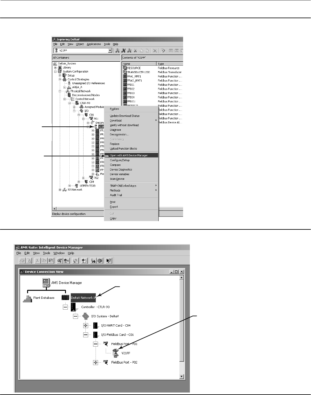
Instruction Manual
D103412X012
Operating with a DeltaV System
January 2015
287
Figure F‐1. Navigating to AMS Device Manager
DIGITAL VALVE
CONTROLLER ICON
AND NAME
OPEN WITH AMS
DEVICE MANAGER
Figure F‐2. Accessing the Digital Valve Controller Through AMS Device Manager
DIGITAL VALVE
CONTROLLER
ICON AND
NAME
LEFT‐CLICK TO
ACCESS THE DELTAV
NETWORK

Instruction Manual
D103412X012
Operating with a DeltaV System
January 2015
288
Methods
Transducer Block
The following methods are accessed via the transducer block: Device Setup, Auto Travel Calibration, Manual Travel
Calibration, Supply Sensor Calibration, Output A Sensor Calibration, Output B Sensor Calibration, Travel Sensor Adjust,
Stroke Valve, Performance Tuner, Stabilize/Optimize, and Relay Adjust.
Refer to figures F‐1, F‐2, and F‐3 and the following steps to access these methods.
1. Start DeltaV Explorer by selecting DeltaV Explorer from the Start menu.
2. Locate the the digital valve controller icon in the All Containers pane (the left panel) and right‐click once on the
digital valve controller icon or name.
3. Locate Open with AMS Device Manager in the context menu and left‐click to bring up the Device Connection View.
4. Navigate to the digital valve controller icon or name as shown in figure F‐2 and left‐click.
5. Locate Methods in the Actions menu, as shown in figure F‐3 and right‐click once.
6. Select the desired method from the the Actions menu and left‐click to start the method.
Resource Block
The Restart Options method and the DD Information method are available via the resource block. Refer to figure F‐3
and the following steps to access these methods.
1. Start DeltaV Explorer by selecting DeltaV Explorer from the Start menu.
2. Locate the digital valve controller icon in the All Containers pane (the left panel) and right‐click once on the digital
valve controller icon or name.
3. Locate Open with AMS Device Manager in the context menu and left‐click to bring up the Device Connection View.
4. Navigate to the digital valve controller icon or name as shown in figure F‐2 and left‐click.
5. Locate Methods in the Actions menu, as shown in figure F‐3 and right‐click once.
6. Select the desired method from the the Actions menu and left‐click to start the method.
Accessing Parameters
Transducer Block
For detailed information on the parameters that are changed via the transducer block, refer to the Detailed Setup
section of this manual. Refer to figures F‐2, F‐3, and F‐4 for information on accessing transducer block parameters.
1. Start DeltaV Explorer by selecting DeltaV Explorer from the Start menu.
2. Locate the digital valve controller icon in the All Containers pane and right‐click once on the digital valve controller
icon or name.
3. Locate Open with AMS Device Manager in the context menu and left‐click to bring up the Device Connection View.
4. Navigate to the digital valve controller icon or name as shown in figure F‐2 and left‐click.
5. Locate Configure/Setup in the Actions menu (see figure F‐3) and left‐click to access Configuration and Setup
parameters.
6. Left‐click on Digital Valve Controller (TRANSDUCER) to access the transducer block parameters. Refer to table F‐1
for the transducer block configuration menu.
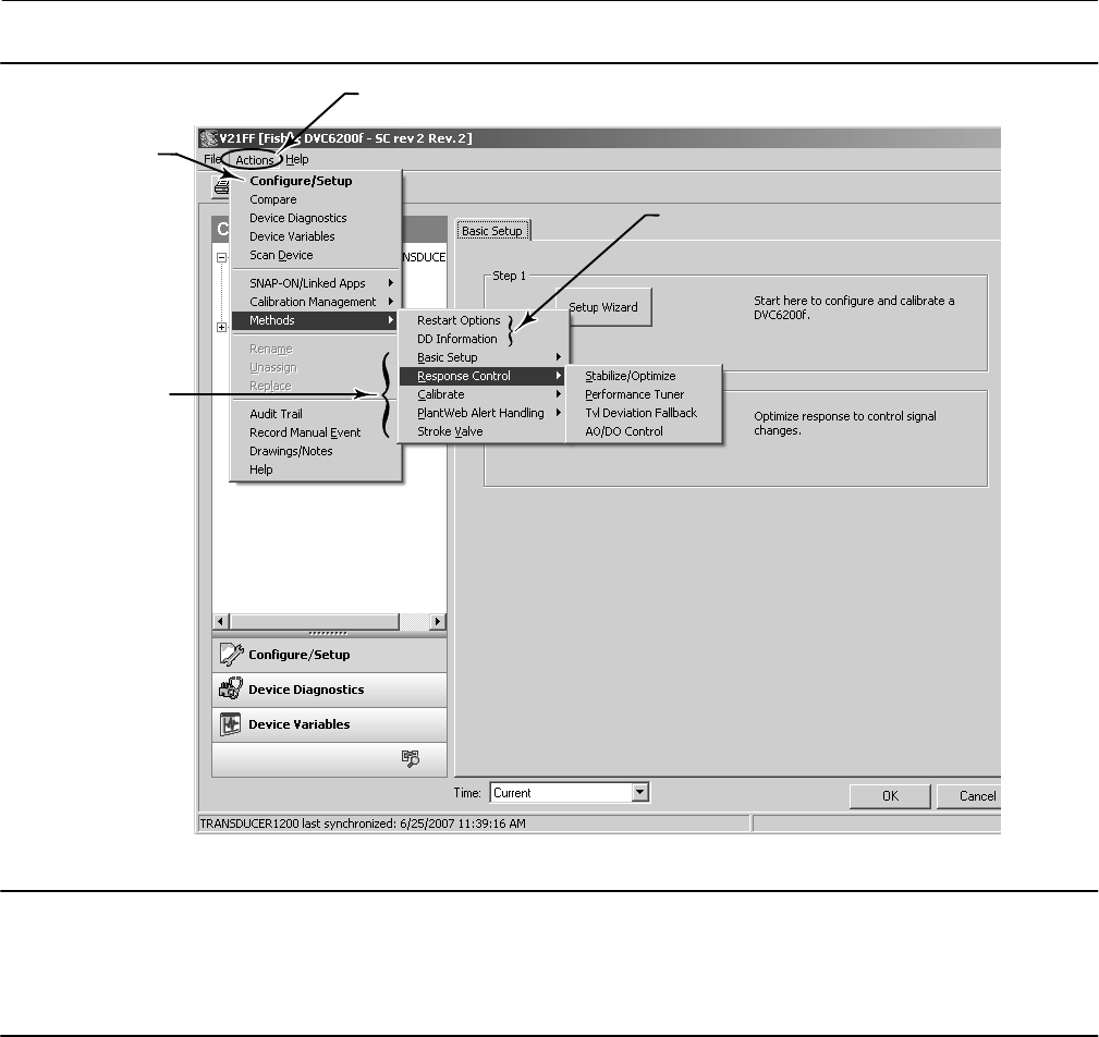
Instruction Manual
D103412X012
Operating with a DeltaV System
January 2015
289
Figure F‐3. Actions Menu
TRANSDUCER
BLOCK METHODS
RESOURCE BLOCK
METHODS
CONFIGURE/SETUP
ACTIONS
Note
To access diagnostic parameters left‐click on Device Diagnostics, and then on Digital Valve Controller (TRANSDUCER). See
figure F‐4.
To access device variables left‐click on Device Variables, and then on Digital Valve Controller (TRANSDUCER). See figure F‐4.
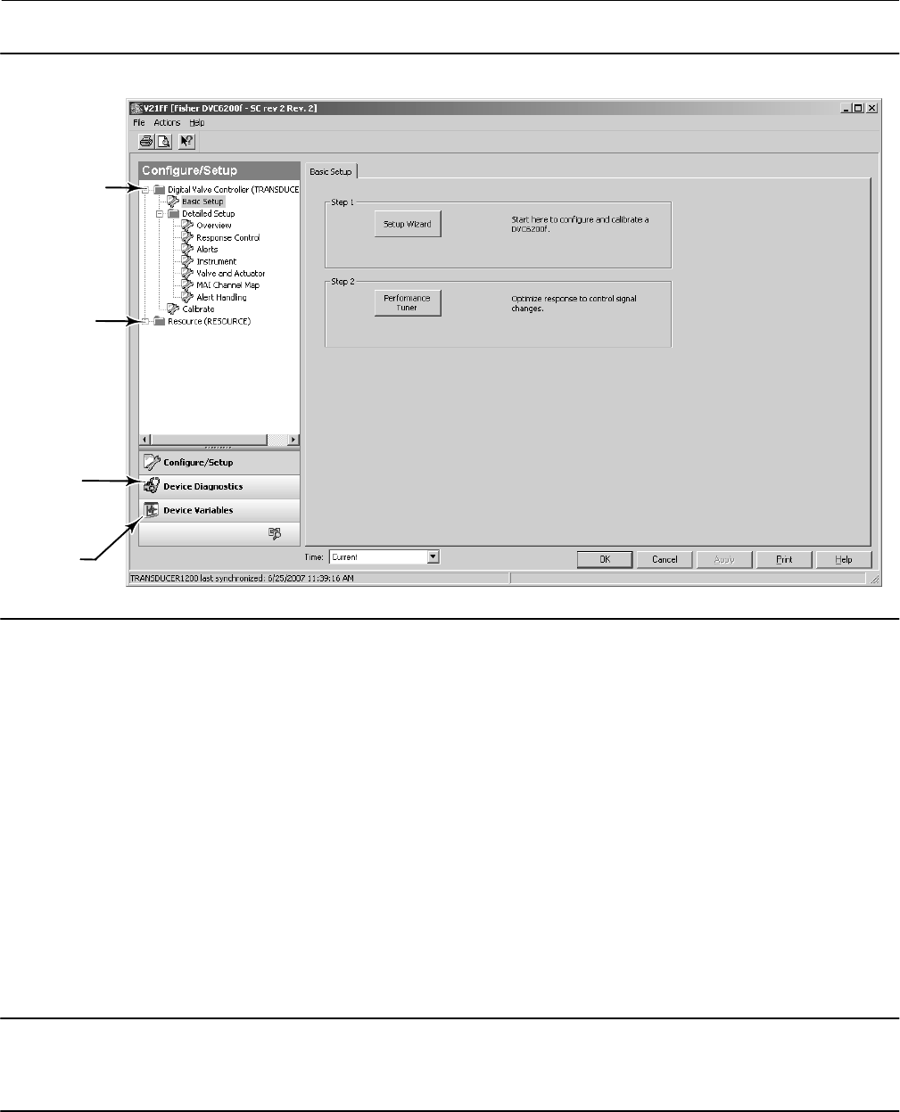
Instruction Manual
D103412X012
Operating with a DeltaV System
January 2015
290
Figure F‐4. Accessing Configure/Setup, Device Diagnostics, and Device Variables
DEVICE
DIAGNOSTICS
DEVICE
VARIABLES
DIGITAL VALVE
CONTROLLER
(TRANSDUCER)
RESOURCE
(RESOURCE)
Resource Block
For detailed information on the parameters that are changed via the resource block, refer to the Detailed Setup
section of this manual. Refer to figures F‐2, F‐3, and F‐4 for information on accessing resource block parameters.
1. Start DeltaV Explorer by selecting DeltaV Explorer from the Start menu.
2. Locate the digital valve controller icon in the All Containers pane and right‐click once on the block icon or name.
3. Locate Open with AMS Device Manager in the context menu and left‐click to bring up the Device Connection View.
4. Navigate to the digital valve controller icon or name as shown in figure F‐2 and left‐click.
5. Locate Configure/Setup in the Actions menu (see figure F‐3) and left‐click to access Configuration and Setup
parameters.
6. Left‐click on Resource (RESOURCE) to access the resource block parameters. Refer to table F‐2 for the resource
block configuration menu.
Note
To access diagnostic parameters left‐click on Device Diagnostics, and then on Resource (RESOURCE). See figure F‐4.
To access device variables left‐click on Device Variables, and then on Resource (RESOURCE). See figure F‐4.

Instruction Manual
D103412X012
Operating with a DeltaV System
January 2015
291
Bringing the Device On‐Line
To completely configure the digital valve controller for use in a fieldbus loop, the following conditions must be met.
Refer to DeltaV On‐Line‐Help or documentation for detailed information on accomplishing these steps.
1. A place holder must be created - a place holder is an electronic representation of the digital valve controller that
exists in the DeltaV database with no associated physical device.
2. Device must be commissioned - Commissioning the device involves downloading applicable parameters from the
device place holder to the physical device.
3. Any additional configuration that is required, such as setting alarms, cutoffs, and other resource block and
transducer block parameters. See the Detailed Setup section of this manual.
4. Define the control strategy
5. Associate I/O to the digital valve controller.
6. The device is now ready to be downloaded.
PlantWeb Alerts
Fieldbus devices detect and report their device alarms to a DeltaV system (or other host system). This includes
detecting whether an alert condition is active, reporting the alarm to DeltaV and later clearing the alarm when the
condition is no longer active. Whether a particular alert condition can be suppressed, disabled or configured off‐line
are all determined by the device.
For Fieldbus, the DeltaV system is responsible for knowing which devices have alarms, ensuring that alarms are
properly represented (such as after controller switchovers) and reporting to operators, Event Chronicle, AMS, OPC
Alarms and Events server, etc. So the only alarms DeltaV shows for a Fieldbus device are those the device has defined
as alarms and has reported to DeltaV.
All device alarms are configured and processed in the DeltaV system identically to process alarms. This means that
how the alarms are communicated within the system, what workstations are notified, alarm annunciation, graphical
representations, event recording, acknowledgement, etc. are identical for process and device alarms. This ensures
that device alarms and process alarms are available to all users and applications in a consistent fashion.
Setting up PlantWeb Alerts
This section walks you through the steps and considerations to implement PlantWeb alerts.
DeltaV Hardware and Software Requirements
The first step to implement PlantWeb alerts is to have the correct hardware and software:
DeltaV v6.3 or later
DeltaV Operate
MD Controllers
Fieldbus devices - While device alerts are supported on all fieldbus devices, devices that offer PlantWeb alerts
provide significantly more useful information.
Series 2 H1 cards
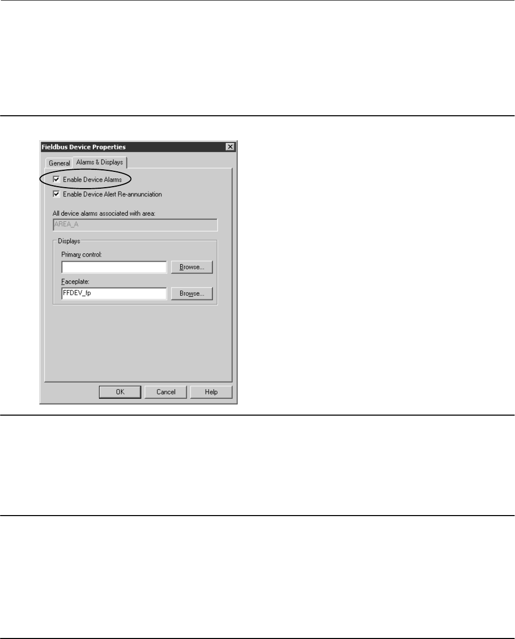
Instruction Manual
D103412X012
Operating with a DeltaV System
January 2015
292
Initial Device Setup
When new FF devices are commissioned on the DeltaV system, device alarms are automatically enabled and default
priorities are assigned to the alarms. Select properties on the device, then the Alarms and Displays tab, as shown in
figure F‐5 to view whether device alarms are enabled on a particular device.
Figure F‐5. Alarms & Display Tab
The Enable Device Alarms configuration option modifies the device configuration. Thus changing this setting requires
a download to the device. Devices that are migrated from older DeltaV systems will have their device alarms disabled.
Note
1. Use the default setting of device alarms enabled. If the user does not want notification of device alarms, this can be configured
on each individual alarm. Later on, you can modify the alarm configurations without downloading the device. Disabling device
alarms disables all of the alarms, including the device communication failure alarm.
2. Use the same control display for the device as for the control module.
3. If you suspect a rogue device is generating extra H1 bus traffic from device alarms, disabling device alarms stops the device from
sending the alarms.
4. If the Alarms and Displays tab is not shown, then you either do not have an MD controller or the device is on a Series 1 H1 card.
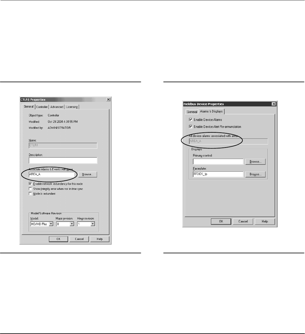
Instruction Manual
D103412X012
Operating with a DeltaV System
January 2015
293
Area Assignment
Controllers use this area assignment to report node status (e.g. not communicating). Devices and control modules use
this area assignment to determine where to send their alarms.
Area A is the default area assignment for all controllers and workstations (see figures F‐6 and F‐7). Also, by default Area
A is assigned to all workstations Alarms and Events subsystem. This means that all controller status problems are sent
to all workstations by default.
Figure F‐6. Controller Properties Figure F‐7. Device Properties
The controller is assigned to Area A. A device that is NOT yet
associated with a control module will default to the same area
as the controller.
A fieldbus device will change its area association once the device is configured to a control module. In addition, the
device is assigned to the same place in the logical hierarchy as this control module. So if the control module is under a
unit, the device is also considered under this same unit.
The device is automatically associated with the same area as the control module that uses the lowest index number
function block in the device. This block is usually the primary input or output function block of the device. This ensures
that wherever the control module is reporting information, all device information that may also be relevant is also
reported.
Note
1. For devices with multiple inputs or outputs (such as the 848), you need to decide which area is best for device alarm reporting
and be sure to assign the correct control module to the lowest index number function block. If there is no module assigned to this
function block, then the device will always be assigned to the same area as the controller.
2. With controller area default of AREA A, and the default of AREA A being assigned to all workstations, you need to evaluate the
alarm settings when commissioning a new fieldbus device with device alarms enabled. If the device detects a FAILED or COM FAIL
alarm prior to being assigned to a control module, this device alarm will be reported and annunciated to all workstations. This is

Instruction Manual
D103412X012
Operating with a DeltaV System
January 2015
294
because all workstations have Area A assigned. Consider lowering the priority of these alarms to ADVISORY until the end of the
commissioning process.
Reporting Alarms and Events to a Workstation
Device alarm and event reporting is no different than control module reporting. Alarm and event reporting to
workstations is determined by assigning areas to workstations. The workstation area assignment is all you need to do
to ensure that you have all of the information (device and process) for that area.
This is important so that ALL of the information about an area -- both the process and device information -- is available
at any workstation that is responsible for that area. That way the Event Chronicle has a complete record for that area,
and any user can drill into a graphic or tag and access all of the information.
This DOES NOT determine WHO views the device alarms. Who views the alarms is determined by filtering at each
workstation.
Now that all of the device (and process) information is assigned to a workstation, the next step is to decide what
priority of device and process alarms cause alarm annunciation to the users on that workstation.
Setting up WHO Sees Device Alarms
The priority of the alarms, and the settings at that workstation determine what alarms are annunciated on a particular
workstation. Annunciated means sound the horn and shown in the alarm banner, Alarm List display, etc.
There are two different approaches that can be used to adjust the device alarm filtering for a particular workstation:
Adjust the default DeltaV Operate alarm settings in the UserRef/UserSettings file
Adjust the individual device alarm priorities
By default, DeltaV Operator Stations have all process alarms are annunciated, and show up on the Alarm Banner, Alarm
List, graphical displays, etc. on all operator workstations. Also by default, the device alarms with priority settings below
WARNING (8) are NOT annunciated or shown in the alarm banner. The low priority device alarms can be shown in
graphics and on summaries defined to not be limited by the alarm settings.
The DeltaV Maintenance Station uses the same DeltaV Operate alarm setting for device alarm annunciation. This
license only shows device alarms on Maintenance Station graphics. NO process alarms are shown in the alarm banner
or ANY alarm summary.
Thus, device alarms and process alarms can be either combined and/or separated for specific user installations, based on
their operating philosophy.
Setting DeltaV Operate Device Alarm Annunciation Defaults
DeltaV Operate has default settings in the UserRef.grf file for what priority of device alarms will annunciate and show
in the alarm banner. The default DeltaV Operate alarm settings annunciate device alarms that are of the priority
WARNING (8) or higher. Device alarms below this priority will not sound the horn or show up in the alarm banner.
Operator Station displays can be configured to show any alarms reporting to that workstation. Along with typical
display configuration, alarm summaries can be configured to display alarms that match the alarm banner settings, or
user specified ranges. The standard AlarmSum display is configured to show all alarms reporting to that workstation
(see figure F‐8).
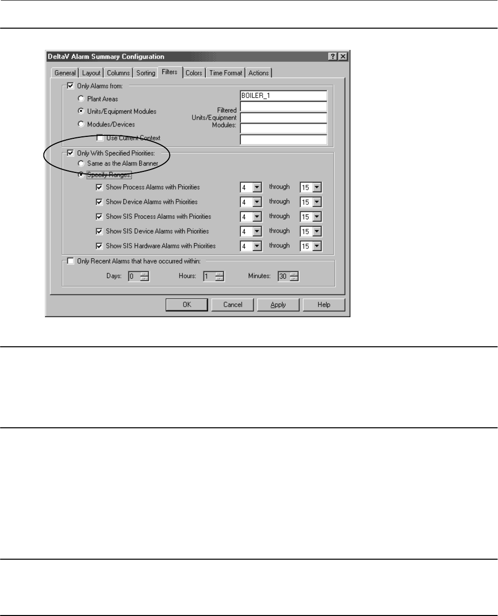
Instruction Manual
D103412X012
Operating with a DeltaV System
January 2015
295
Figure F‐8. DeltaV Alarm Summary Configuration
Each display alarm summary can be configured to
match the alarm banner or be uniquely defined.
Note
If you think you should be seeing a device alarm in the alarm banner and it is not there, verify that the device is shown on the
AlarmSum display. This display shows ALL of the alarms reporting to that workstation, regardless of the device alarm annunciation
settings. If the device is not shown in this display, then it is not reporting to this workstation (or the logged on user does not have
responsibility for that area).
The default for device alarm annunciation (sounds the horn and shown in the alarm banner) can be modified for all
operator/maintenance stations. Or unique settings can be defined for specific workstations. Use the workstation name
to adjust settings for specific workstations in UserSettings.grf.
For example, if an installation has a Maintenance Station named 'MAINT', then the UserRef.grf (then renamed to
UserSettings.grf) would contain alarm settings for the MAINT workstation as appropriate for maintenance (e.g. all
device alarms in the alarm banner).
Note
To easily find the device alarm configuration in UserRef or UserSettings, open the display in the Standard directory, right click and
select EDIT SCRIPT, then select Edit, Find and type in DEVICE. This will take you to the location in the file with the device alarm
settings.
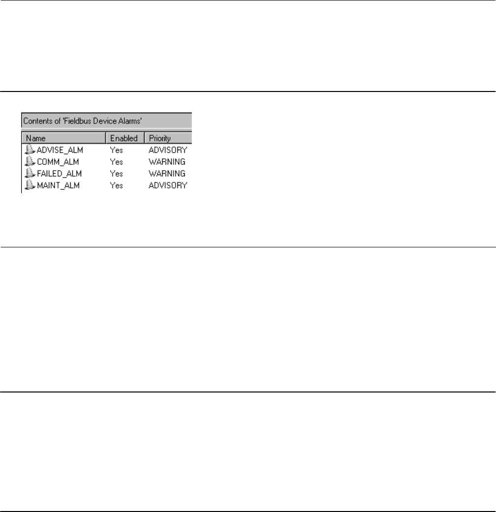
Instruction Manual
D103412X012
Operating with a DeltaV System
January 2015
296
Deciding Device Alarm Priorities
Each device alarm, just like every process alarm, has a priority assigned to it. When a device is created, the device
alarms are assigned default alarm priorities as shown in figure F‐9.
Figure F‐9. Default PlantWeb Alert Priorities
The priority of a device alarm defines whether the
alarm is annunciated on a particular workstation, in
addition to the color of the alarm and the horn sound.
The DeltaV workstation default is to annunciate device alarms above the ADVISORY (7) priority.
Therefore, by default both the FAILED and COMM PlantWeb alerts annunciate to the operator.
The priority of each alarm needs to be considered. The priority of a device alarm is determined by how important that
device problem is and the consequences to the process.
The priority is not based solely on the type of device. This means that while some DVC6200f's may be critical to
operation, other DVC6200f's may not. In this example, the DVC6200f's would have different default alarm priorities.
Note
1. If your installation has the Fieldbus devices, but is not ready to use PlantWeb alerts, then you can disable the individual alarms at
the device - or through the System Alarm Management application. Later on, individual alarms can be enabled without having to
download the device.
2. When you first begin to use device alarms, be sure that your alarm priority settings for the workstations or the individual device
alarm priorities are such that they don't cause undue operator burden. This could mean only having a few device alarms set at
WARNING or above, or changing the DeltaV Operate default such that only CRITICAL device alarms (or even perhaps NO device
alarms annunciate to the operator).
3. DO NOT enable ALL of the PlantWeb alerts in a device. Only enable the alerts that are needed.

Instruction Manual
D103412X012
Glossary
January 2015
297
Glossary
Algorithm
A set of logical steps to solve a problem or
accomplish a task. A computer program contains
one or more algorithms.
Alphanumeric
Consisting of letters and numbers.
ANSI (acronym)
The acronym ANSI stands for the American
National Standards Institute
ANSI Class
Valve pressure/temperature rating.
Bench Set
Pressure, supplied to an actuator, required to
drive the actuator through rated valve travel.
Expressed in pounds per square inch.
Byte
A unit of binary digits (bits). A byte consists of
eight bits.
Configuration
Stored instructions and operating parameters for
a FIELDVUE Instrument.
Control Loop
An arrangement of physical and electronic
components for process control. The electronic
components of the loop continuously measure
one or more aspects of the process, then alter
those aspects as necessary to achieve a desired
process condition. A simple control loop
measures only one variable. More sophisticated
control loops measure many variables and
maintain specified relationships among those
variables.
Controller
A device that operates automatically to regulate a
controlled variable.
Deadband
Region around a reference point that must be
exceeded before a new event occurs.
Deviation
Usually, the difference between set point and
process variable. More generally, any departure
from a desired or expected value or pattern.
Device ID
Unique identifier embedded in the instrument at
the factory.
Drive Signal
The signal to the I/P converter from the printed
wiring board. It is the percentage of the total
microprocessor effort needed to drive the valve
fully open. In most applications, drive signal
ranges from 55% to 75%.
Feedback Arm
The mechanical connection between the valve
stem linkage and the FIELDVUE Instrument travel
sensor.
Feedback Signal
Indicates to the instrument the actual position of
the valve. The travel sensor provides the feedback
signal to the instrument printed wiring board
assembly. A mechanical linkage connects the
travel sensor to the valve stem or shaft.
Firmware
The combination of a hardware device and
computer instructions and data that reside as
read‐only software on that device.
Note
1. This term (firmware) is sometimes used to refer only to
the hardware device or only to the computer instructions or
data, but these meanings are deprecated.
2. The confusion surrounding this term has led some to
suggest that it be avoided altogether. The term is included
here because of its use in older documentation and culture.

Instruction Manual
D103412X012
Glossary
January 2015
298
Gain
The ratio of output change to input change.
Hardware Revision
Revision number of the Fisher instrument
hardware. The physical components of the
instrument are defined as the hardware.
Instrument Level
Determines the functions available for the
instrument.
Leak Class
Defines the allowable leakage by a valve when it is
closed. Leak class numbers are listed in two
standards: ANSI/FCI 70‐2 and IEC 534‐4.
Linearity, dynamic
Linearity (independent) is the maximum
deviation from a straight line best fit to the
opening and closing curves and a line
representing the average value of those curves.
Memory
A type of semiconductor used for storing
programs or data. FIELDVUE instruments use
three types of memory: Random Access Memory
(RAM), Read Only Memory (ROM), and
Non‐Volatile Memory (NVM).
Non‐Volatile Memory (NVM)
A type of semiconductor memory that retains its
contents even though power is disconnected.
NVM contents can be changed during
configuration unlike ROM which can be changed
only at time of instrument manufacture. NVM
stores configuration restart data.
Octet
See byte
Parallel
Simultaneous: said of data transmission on two or
more channels at the same time.
Pressure Sensor
A FIELDVUE instrument internal device that
senses the output pressure from the pneumatic
relay.
Random Access Memory (RAM)
A type of semiconductor memory that is normally
used by the microprocessor during normal
operation that permits rapid retrieval and storage
of programs and data. See also Read Only
Memory (ROM) and Non‐Volatile Memory (NVM).
Rate
Amount of change in output proportional to the
rate of change in input.
Read‐Only Memory (ROM)
A memory in which information is stored at the
time of instrument manufacture. You can
examine but not change ROM contents.
Seat Load
Force exerted on the valve seat, typically
expressed in pounds force per lineal inch of port
circumference. Seat load is determined by shutoff
requirements.
Software
Computer programs, procedures, and possibly
associated documentation and data pertaining to
the operation of a computer system.
Temperature Sensor
A device within the FIELDVUE instrument that
measures the instrument's internal temperature.
Travel
Movement of the valve stem or shaft which
changes the amount the valve is open or closed.
Travel Sensor
A device within the FIELDVUE instrument that
senses valve stem or shaft movement. The travel
sensor in the DVC6200f is the Hall Effect sensor
that measures the position of the magnet
assembly.

Instruction Manual
D103412X012
Glossary
January 2015
299
Travel Sensor Motion
Increasing or decreasing air pressure causes the
magnet assembly to move up or down or the
rotary shaft to turn clockwise or
counterclockwise. Device Setup asks if it can
move the valve to determine travel.
Tuning
The adjustment of control terms or parameter
values to produce a desired control effect.
Tuning Set
Preset values that identify gain and rate settings
for a FIELDVUE instrument. The tuning set and
supply pressure together determine an
instrument's response to input signal changes.
Watch Dog Timer
A timer that the microprocessor must pulse
periodically. If the microprocessor is unable to
pulse the timer, the instrument shuts down.
Zero Power Condition
The position of the valve (open or closed) when
the electrical segment power to the instrument is
removed. Zero Power Condition (ZPC) is
determined by relay and actuator action where:
for Relay A and C, Port A will be at atmosphere
pressure, and if double‐acting, Port B will be at
supply pressure. For Relay B, Port B will be at
supply pressure.

Instruction Manual
D103412X012
Glossary
January 2015
300

Instruction Manual
D103412X012
Index
January 2015
301
Index
A
Acknowledge Option, Resource Block, 24
Act On IR, 107
Action on Failure, DI Function Block, 181
Action on Fault Detection
AO Function Block, 94
DO Function Block, 170
Active PlantWeb Alerts, 200
Actuator
Fail Action, 59
Manufacturer, 59
Model Number, 59
Serial Number, 59
Size, 59
Style, 59
Device Setup, 18
Actuator Compatibility, 8
Actuator Information, for initial setup, 17
Advanced Diagnostics (AD), 4
Air, 60
as supply medium, 7
Alarm Detection
AI Function Block, 147
DI Function Block, 181
ISEL Function Block, 127
PID Function Block, 107
Alarm Handling, 23
Alarm Priorities
ISEL Function Block, 128
PID Function Block, 108
Alert Conditions, 200
Instrument, 45
Alert Handling, 62
PlantWeb Alert Handling, 62
PlantWeb Alert Simulate, 62
PlantWeb Alerts, 251
Simulate Active Alerts, 62
Alert Key, 48
Alert Reporting, PlantWeb Alerts, 253
Alerts
Configuration, 47
Electronics, 45
Environment, 49
Instrument, 45
Performance, 55
PlantWeb, 45
Proximity, 52
Sensor, 48
Travel, 50
AMS Device Manager, using, 286
Analog Input (AI) Function Block, 5, 147
Advanced Features, 151
Alarm Detection, 147
Block Errors, 151
Field Communicator Menu Structure, 158
Filtering, 150
Modes, 147
parameters, 152
Signal Conversion, 150
Simulation, 151
Status Handling, 149
Troubleshooting, 152
View Lists, 156
Analog Output (AO) Function Block, 5, 89
Action on Fault Detection, 94
Application Information, 95
Block Errors, 95
Field Communicator Menu Structure, 101
I/O Options, 94
Mode Handling, 91
parameters, 96
Set Point Selection and Limiting, 93
Setting the Output, 92
Simulation, 95
Status Handling, 92
View Lists, 100
ANSI/ISA‐75.13.01 Section 5.3.5, Vibration Testing
Method, 8
AO Control - Pre‐Characterization, Device Variables,
206
AO Control‐Post Characterization, Device Variables,
206
Application Information
AO Function Block, 95
DI Function Block, 182
MAI Function Block, 160
PID Function Block, 108
Area Units, 57
ATEX, hazardous area approval, 8

Instruction Manual
D103412X012
Index
January 2015
302
Auto Calibration, 190
B
Backup Link Master, 7
Basic Setup, 15
Bench Set
Lower, 60
Upper, 60
Block Alarm, Resource Block, 197
Block Alarm Auto Acknowledge, Resource Block, 24
Block Alarm Disabled, Resource Block, 24
Block Error
Resource Block, 196
Transducer Block, 203
Block Error Reporting, 62
Block Errors, 62
AI Function Block, 151
AO Function Block, 95
DI Function Block, 181
DO Function Block, 170
ISEL Function Block, 128
MAI Function Block, 160
PID Function Block, 108
Resource Block, 25
Block Execution Times, 7
Block Initialization
DI Function Block, 178
DO Function Block, 168
Block Modes, 265
All, Device Variables, 205
DVC6200f, 265
Blocks
Function, 5
Resource Block, 5
Transducer Block, 5
Blocks Set to Default, Alerts, 48
C
Calibration, 189
Auto, 190
Manual, 190
Pressure A or B Sensor, 193
Relay, 191
Supply Pressure Sensor, 192
Calibration Date, 57
Calibration Location, 57
Calibration Person, 57
Classifications, Other
CUTR, 8
INMETRO, 8
KGS, 8
Natural Gas Certified, Single Seal Device, 8
NEPSI, 8
TIIS, 8
PESO CCOE, 8
Clear Fault State, Resource Block, 198
Communication Connections, 12
Communication Time Out, 22
Shed Remote Cascade, 22
Shed Remote Out, 22
Configuration Alerts, 47, 200
Alert Key, 48
Blocks Set to Default, 48, 201
Output Block Timeout, 47, 200
Configuration, Initial, 3
Configure/Setup, 21
Confirm Time, 24
Connections
Communications, 12
Electrical, 3
Pneumatic, 3
Specifications, 8
Construction Materials, 9
control options, PID Function Block, 106
Control selections, 4
CSA, hazardous area approval, 8
Custom Characterization, 44
Customs Union Technical Regulations (CUTR), Russia,
Kazakhstan and Belarus, Certification, 8
Cycle Counter
Alerts, 54
Device Variables, 207
D
DD Information, 199
Declaration of SEP, 9
DeltaV ProfessionalPLUS Workstation, Installing DD
on, 274

Instruction Manual
D103412X012
Index
January 2015
303
DeltaV System
operating with, 279
Software Functionality/System Requirements, 286
DeltaV Tune, for PID control loops, 108
Detailed Setup, 1, 38
Device Addressing, 269
Device Communication, 270
Scheduled Transfers, 270
Unscheduled Transfers, 271
Device Description, Overview, 273
Device Description Version, displaying, 277
Device Descriptions, 267
Installing on a DeltaV ProfessionalPLUS Workstation,
274
Installing on Other Fieldbus Host Systems, 276
Device Diagnostics
Resource Block, 196
Transducer Block, 200
Device ID, 24, 198
Device Revision, 25, 199
Device Setup, 16
Device State, Resource Block, 196
Device Type, 24, 199
Device Variables
Resource Block, 198
Transducer Block, 205
diagnostic capabilities, 4
Diagnostic Options, 22, 25, 199
Digital Communication Protocol, 7
Direct Action, PID Function Block, 107
Direct Selection of Inputs, ISEL Function Block, 127
Direct signal conversion, AI Function Block, 150
Disabling Inputs, ISEL Function Block, 126
Discrete Alarm Auto Acknowledge, 24
Discrete Alarm Disabled, 24
Discrete Input (DI) Function Block, 5, 177
Action on Failure, 181
Alarm Detection, 181
Application Information, 182
Block Errors, 181
Block Initialization, 178
Field Value Processing, 180
I/O Selection, 178
Modes, 178
parameters, 182
Simulation, 181
Status Handling, 178
View Lists, 186
Discrete Output (DO) Function Block, 5, 165
Action on Fault Detection, 170
Block Errors, 170
Block Initialization, 168
I/O Selection, 168
Mode Handling, 167
Modes, 166
Output Block PV Status, 169
parameters, 171
Setting the Output, 168
Shed Options — RCAS Mode Only, 167
Simulation, 170
Status Handling, 168
View Lists, 175
DO Control, Device Variables, 206
Double‐Acting Relay, calibration, 191
Drive Current, Alerts, 45
Drive Signal
Alerts, 46
Device Variables, 207
E
Educational Services, 10
Effective Area, 60
Electrical Classification
Electrical Housing, 8
Hazardous Area Approvals, 8
Electrical Connections, 3
Electrical Housing, 8
Electromagnetic Compatibility, Specification, 8
Electronics Alerts, 45, 200
Drive Current, 45, 200
Drive Signal, 46, 200
Processor Impaired, 46, 200
Electronics Serial Number, 24, 198
EMC Summary Results—Immunity, 9
EN 61326-1 (First Edition), 8
Enable Jumper, Simulate, 13
Environment Alerts, 49, 201
Supply Pressure, 49, 201
Temperature Limit, 50, 201

Instruction Manual
D103412X012
Index
January 2015
304
Expert tuning, 19
Pressure, 42
Travel, 39
F
Factory Serial Number, 24, 198
Fail Action, Actuator, 59
Fault State, Resource Block, 198
Features Available, 23
Features Selected, 23
Feedback Connection Options, 59
Feedforward Calculation, PID Function Block, 106
Field Communicator Menu Structure
AI Function Block, 158
AO Function Block, 101
DO Function Block, 176
ISEL Function Block, 135
MAI Function Block, 164
OS Function Block, 146
Field Serial Number, 24, 198
Field Value Processing, DI Function Block, 180
Fieldbus Connections, Quick Connect Cable Entry, 11
Fieldbus Control (FC), 4
Fieldbus Diagnostics (FD), 4
Fieldbus Installation and Wiring Guidelines, 10
Fieldbus Logic (FL), 4
Filtering
AI Function Block, 150
PID Function Block, 106
Firmware Revision, 25, 199
Flow Direction, 58
FM, hazardous area approval, 8
Function Block
Input Selector (ISEL), 121
Overview, 263
Function Block Options, 22, 199
Function Block Scheduling, 272
Function Blocks, 5
Analog Input (AI), 5, 147
Analog Output (AO), 5, 89
Discrete Input (DI), 177
Discrete Output (DO), 5, 165
Input Selector (ISEL), 5
Multiple Analog Input (MAI), 5, 159
Output Splitter (OS), 5, 136
Proportional-Integral-Derivative (PID), 5, 102
G
Gain Values, preselected tuning sets, 19
Gauges, Pipe Plugs, or Tire Valves, maintenance, 217
H
Hardware Revision, 25, 199
Hazardous Area Approvals, 8
ATEX, 8
CSA, 8
FM, 8
IECEx, 8
Humidity Testing, Method, 8
I
I/O Options, AO Function Block, 94
I/O Selection
DI Function Block, 178
DO Function Block, 168
I/P Converter
maintenance, 213
removing, 214
replacing, 214
I/P Filter, replacing, 213
Identification of Selected Inputs, ISEL Function Block,
127
IEC 61514-2, humidity testing method, 8
IECEx, hazardous area approval, 8
Independent Linearity, Specification, 8
Indirect signal conversion, AI Function Block, 150
Indirect Square Root, AI Function Block, 150
Initialization and Back Calculation Requirements, OS
Function Block, 141
INMETRO, Brazil, Certification, 8

Instruction Manual
D103412X012
Index
January 2015
305
Input Characterization, 43
Device Variables, 206
Input Selection, ISEL Function Block, 126
Input Selector (ISEL) Function Block, 5, 121
Alarm Detection, 127
Alarm Priorities, 128
Block Errors, 128
Field Communicator Menu Structure, 135
Input Selection, 126
Direct Selection of Inputs, 127
Disabling Inputs, 126
Identification of Selected Inputs, 127
Modes, 121
parameters, 128
Status Handling, 122
Limit Propagation, 123
Quality Use and Propagation, 122
STATUS_OPTS Supported, 126
Substatus Propagation, 123
View Lists, 133
Input to Output Mapping, OS Function Block, 139
Installation, 3
Instrument Alert, Conditions, 251
Instrument Alert Conditions, 45, 200
ISO 8573-1, Supply Medium, 7
ITK Version, 25, 199
K
KGS, Korea Gas Safety Corporation, Certification, 8
L
Last Calibration Type, 57
Leak Class, 58
Length Units, 57
Lever Arm Length, 60
Lever Style, 60
Lightning and Surge Protection, 8
Limit Handling, OS Function Block, 139
Limit Notify, 24
Limit Propagation
ISEL Function Block, 123
Transducer Block, 268
Link Active Scheduler (LAS), 269
Lower Bench Set, 60
M
Magnetic Feedback Assembly, removing, 210
MAI Channel Map, 61
MAI Function Block, parameters, 161
Maintenance
Gauges, Pipe Plugs, or Tire Valves, 217
I/P Converter, 213
Module Base, 210, 211
Pneumatic Relay, 216
PWB Assembly, 215
Resource Block, 197
Terminal Box, 217
Tools Required, 210
Manual Calibration, 190
Manufacturer Identification, 24, 199
Maximum Notify, 24
Maximum Output Capacity, Specification, 7
Maximum Recorded Supply Pressure, 204
Maximum Recorded Supply Pressure Time, 204
Maximum Recorded Temperature, 204
Maximum Recorded Temperature Time, 204
Maximum Supply Pressure, 57
Methods, 274
Minimum Recorded Supply Pressure, 204
Minimum Recorded Supply Pressure Time, 204
Minimum Recorded Temperature, 204
Minimum Recorded Temperature Time, 204
Miscellaneous Options, 23, 199
Mode Handling
AO Function Block, 91
DO Function Block, 167
PID Function Block, 104
Modes
AI Function Block, 147
AO Function Block, 90
Blocks, 265
DI Function Block, 178
DO Function Block, 166
Explanation of, 266
ISEL Function Block, 121

Instruction Manual
D103412X012
Index
January 2015
306
MAI Function Block, 159
OS Function Block, 137
PID Function Block, 104
Resource Block, 21
Transducer Block, 38
Module Base
removing, 211
replacing, 212
Mounting, Troubleshooting, 219
Multiple Analog Input (MAI) Function Block, 5, 159
Application Information, 160
Field Communicator Menu Structure, 164
Modes, 159
Status Handling, 159
View Lists, 163
N
natural gas, as supply medium, 7, 209
Natural Gas Certified, Single Seal Device, Other
Classifications/Certifications, 8
NEPSI, China, Certification, 8
Network Communication, 269
Network Management, 272
Nominal Supply Pressure, 60
O
Open/Closed Limit Switch, Channel 24 and 25, DI
Function Block, 179
Options, 9
Resource Block
Diagnostic, 22
Features Available, 23
Features Selected, 23
Function Block, 22
Miscellaneous, 23
Outblock Selection, 45
Output Block PV Status, 61
AO Function Block, 93
DO Function Block, 169
Output Block Timeout, Alerts, 47
Output Selection and Limiting, PID Function Block, 106
Output Signal, Specifications, 7
Output Splitter (OS) Function Block, 5, 136
Field Communicator Menu Structure, 146
Initialization and Back Calculation Requirements,
141
Modes, 137
parameters, 143
Status Handling, 138
View Lists, 145
Output Tracking, PID Function Block, 106
P
Parameters
AI Function Block, 152
AO Function Block, 96
DI Function Block, 182
DO Function Block, 171
ISEL Function Block, 128
MAI Function Block, 161
OS Function Block, 143
PID Function Block, 109
Resource Block, 30
Transducer Block, 63
Parts Kits, 225
Parts List, 226
Parts Ordering, 225
PD Inside Status
Alert, 55
Device Variables, 207
PD Run, Alert, 56
Performance Alerts, 55, 202
PD Inside Status, 55
PD Run, 56
Performance Critical, 56, 202
Performance Information, 56
Performance Reduced, 56
Performance Critical, Alerts, 56
Performance Diagnostics (PD), 4
Performance Information, Alerts, 56
Performance Reduced, Alerts, 56
Performance Tuner, 19, 20, 40
PESO CCOE, India, Certification, 8
PID Equation Structures for Enhanced PID Block, 107
PID Function Block, 102
Alarm Detection, 107
Alarm Priorities, 108

Instruction Manual
D103412X012
Index
January 2015
307
Application Information, 108
Block Errors, 108
Feedforward Calculation, 106
Filtering, 106
Mode Handling, 104
Modes, 104
Output Selection and Limiting, 106
Output Tracking, 106
parameters, 109
Reverse and Direct Action, 107
Set Point Tracking, 106
Status Handling, 105
PlantWeb Alert Enable, 56
Advise Enable, 56
Failed Enable, 56
Maintenance Enable, 56
PlantWeb Alert Handling, Alert Handling, 62
PlantWeb Alert Reporting, 56
Advise Suppress, 57
Failed Suppress, 56
Maintenance Suppress, 56
PlantWeb Alert Simulate, Alert Handling, 62
PlantWeb Alerts, 45
Alert Handling, 251
Alert Reporting, 253
Conditions, 251
Configuration, 47
Electronics, 45
Environment, 49
in a DeltaV System, 291
Mode-Based, 251
Performance, 55
Proximity, 52
Sensor, 48
Set Block Status, 253
Setting, 253
Travel, 50
Travel History, 54
Using, 253, 257
PlantWeb Alerts Set PV Status, 62
Pneumatic Connections, 3
Pneumatic Relay
removing, 216
replacing, 216
Port Diameter, 58
Port Type, 58
Pressure A or B Sensor, calibration, 193
Pressure Cutoff Closed, 43
Pressure Cutoff Open, 43
Pressure Fallback, Alerts, 49
Pressure Fallback Auto Recovery, 42
Pressure Fallback Manual Recovery, 42
Pressure Integral Dead Zone, 42
Pressure Integral Gain, 42
Pressure Integral Limit Hi, 42
Pressure Integral Limit Lo, 42
Pressure MLFB Gain, 42
Pressure Proportional Gain, 42
Pressure Range Hi, 43
Pressure Range Lo, 43
Pressure Sensors, Alerts, 48
Pressure Tuning, 41
Pressure Tuning Set, 41
Pressure Tuning Sets, Gain Values, 42
Pressure Units, 57
Pressures, 208
Principle of Operation, Block Diagram, 235
Printed Wiring Board (PWB) Assembly
removing, 215
replacing, 215
Processor Impaired, Alerts, 46
Proportional‐Integral‐Derivative (PID) Function Block,
5
Protection, 15, 38
Device Variables, 207
Proximity, Alerts, 53
Proximity Alerts, 52, 201
Proximity, 53, 202
Travel, 52
Travel Closed, 53, 202
Travel Open, 53, 201
Push Down To, 58
Q
Quality Use and Propagation, ISEL Function Block, 122
Quick Connect Cable Entry, 11

Instruction Manual
D103412X012
Index
January 2015
308
R
Related Documents, 10
Relay, calibration, 191
Relay A, 191
Relay B, 16, 191, 192
Relay C, 191, 192
Relay Type, 57
Resource Block, 264
Block Alarm, 197
Block Errors, 25
Clear Fault State, 198
Device State, 196
Device Variables, 198
Options
Diagnostic, 199
Features Available, 199
Function Block, 199
Miscellaneous, 199
Overview, 21
parameters, 30
Restart Actions, 197
Set Fault State, 198
Strategy, 198
Tag Description, 198
View Lists, 37
Device Diagnostics, 196
Write Lock, 196
Resource Block (RB)
Menu Structure, 248
Menu Tree, 249
Resource Block Error, 196
Resource Block Mode, 21
Response Control, 39
Restart Actions, Resource Block, 197
Restart Processor, Resource Block, 198
Restart with Defaults
parameters affected by, 26
Resource Block, 198
Reverse Action, PID Function Block, 107
S
Scheduled Transfers, Device Communication, 270
Seat Type, 58
Self Test Status, 202
Sensor Alerts, 48, 201
Pressure Fallback, 49, 201
Pressure Sensors, 48, 201
Temperature Sensor, 201
Travel Sensor, 201
Travel Sensor Alert, 48
Serial Number
Actuator, 59
Electronics, 24, 198
Factory, 24, 198
Field, 24, 198
Valve, 58
Set Block Status, PlantWeb Alerts, 253
Set Fault State, Resource Block, 198
Set Point Selection and Limiting, AO Function Block,
93
Set Point Tracking, PID Function Block, 106
Setting the Output
AO Function Block, 92
DO Function Block, 168
Output Block PV Status, AO Function Block, 93
Shed Options — RCAS Mode Only, DO Function Block,
167
Shed Options—RCAS Mode Only
AO Function Block, 91
PID Function Block, 104
Signal Conversion, AI Function Block, 150
Simulate Active Alerts, Alert Handling, 62
SIMULATE ENABLE terminals, 13
Simulation
AI Function Block, 151
AO Function Block, 95
DI Function Block, 181
DO Function Block, 170
Single‐Acting Relays, calibration, 192
SP Track retained Target, 106
SP-PV Track in LO or IMan, 106
SP-PV Track in Man, 106
SP-PV Track in ROUT, 106
Specifications, DVC6200f, 7
Spring Rate, 60
Spring Rate Units, 57
Stabilize/Optimize, 19, 40

Instruction Manual
D103412X012
Index
January 2015
309
Standard Control (SC), 4
Standby Firmware Revision, 25, 199
static discharge, avoiding, 209
Status Handling
AI Function Block, 149
AO Function Block, 92
DI Function Block, 178
DO Function Block, 168
ISEL Function Block, 122
MAI Function Block, 159
OS Function Block, 138
PID Function Block, 105
Status Propagation, Transducer Block, 268
STATUS_OPTS Supported, ISEL Function Block, 126
Steady-State Air Consumption, Specifications, 7
Strategy, Resource Block, 24, 198
Stroking the Digital Valve Controller Output, 218
Stroking Time Close, 60
Stroking Time Open, 60
Substatus Propagation, ISEL Function Block, 123
Supply Medium, per ISO 8573-1, 7
Supply Pressure
Alerts, 49
Maximum, 57
Maximum Recorded, 204
Minimum Recorded, 204
Specifications, 7
Supply Pressure Sensor, calibration, 192
T
Tag Description
Resource Block, 24, 198
Transducer Block, 57
Temperature
Device Variables, 207
Maximum Recorded, 204
Minimum Recorded, 204
Temperature Limit, Alerts, 50
Temperature Limits, Operating Ambient, 8
Temperature Units, 57
Terminal Box
removing, 217
replacing, 218
TIIS, Japan, Certification, 8
Transducer Block, 264
Block Error, 203
Device Diagnostics, 200
Device Variables, 205
parameters, 63
Status and Limit Propagation, 267
View Lists, 86
Transducer Block (TB)
Menu Structure, 238
Menu Tree, 243, 244, 245, 246, 247
Transducer Block Mode, 15, 38
Transducer Block Overview, 38
Travel, Alert, 50, 52
Travel Accumulator
Alerts, 54
Device Variables, 207
Travel Alerts, 50, 201
Travel, 50
Travel Deviation, 50, 201
Travel Hi/Lo, 52, 201
Travel Limit, 51, 201
Travel Target, 50
Travel Closed, Alerts, 53
Travel Count, Device Variables, 207
Travel Cutoff Hi, 43
Travel Cutoff Lo, 43
Travel Deviation, Alerts, 50
Travel Deviation Pressure Fallback, 43
Travel Hi/Lo, Alerts, 52
Travel History, Alerts, 54
Travel History Alerts, 54, 202
Cycle Counter, 54, 202
Travel Accumulator, 54, 202
Travel Integral Dead Zone, 40
Travel Integral Enable, 40
Travel Integral Gain, 40
Travel Integral Limit Hi, 40
Travel Integral Limit Lo, 40
Travel Limit, Alerts, 51
Travel MLFB Gain, 40
Travel Open, Alerts, 53
Travel Pressure Control, 42
Travel Proportional Gain, 40

Instruction Manual
D103412X012
Index
January 2015
310
Travel Sensor, Alerts, 48
Travel Sensor Motion, 59, 60
Device Setup, 18
Travel Target, Alert, 50
Travel Tuning, 39
Travel Tuning Set, 39
Travel Tuning Sets, Gain Values, 39
Travel Units, 57
Travel Velocity Gain, 40
Travel/Pressure Select, 42
Travel/Pressure State, 42
Device Variables, 207
Trend, 205
Trim Style 1, 60
Trim Style 2, 60
Troubleshooting
AI Function Block, 152
DVC6200f, 219
MAI Function Block, 160
mounting, 219
utility connections, 219
Tuning
Pressure, 41
Travel, 39
Tuning Set
Device Setup, 19
Pressure, 41
Travel, 39
Tuning Set B, 19
Tuning Sets, Gain Values, 19
U
Unbalanced Area, 58
Unscheduled Transfers, Device Communication, 271
Upper Bench Set, 60
Utility Connections, Troubleshooting, 219
V
Valve
Actual Travel, 58
Class, 58
Inlet Pressure, 58
Manufacturer, 58
Model Number, 58
Outlet Pressure, 58
Packing Type, 58
Serial Number, 58
Shaft Stem Diameter, 58
Size, 58
Style, 58
Device Setup, 18
Valve Position Proximity Detection, Channels 30-33, DI
Function Block, 179
Valve Travel, Channel 23, DI Function Block, 178
Variable Limit Switch, Channels 26-29, DI Function
Block, 179
Vibration Testing, Method, 8
View / Edit Feedback Connection, 59
View Lists, 195
AI Function Block, 156
Analog Output (AO) Function Block, 100
DI Function Block, 186
DO Function Block, 175
ISEL Function Block, 133
MAI Function Block, 163
OS Function Block, 145
PID Function Block, 117
Resource Block, 37
Transducer Block, 86
W
Weight
DVC6200f, 8
DVC6205f, 8
DVC6215, 8
Wiring and Electrical Connections, Communication
Connections, 12
Wiring Practices, 11
Write Alarm, 24
Write Lock, 21
Resource Block, 196
Write Lock, 21
Write Priority, 22
Z
Zero Power Condition, 57
Device Setup, 18

N97
Emerson Process Management
Marshalltown, Iowa 50158 USA
Sorocaba, 18087 Brazil
Chatham, Kent ME4 4QZ UK
Dubai, United Arab Emirates
Singapore 128461 Singapore
www.Fisher.com
The contents of this publication are presented for informational purposes only, and while every effort has been made to ensure their accuracy, they are not
to be construed as warranties or guarantees, express or implied, regarding the products or services described herein or their use or applicability. All sales are
governed by our terms and conditions, which are available upon request. We reserve the right to modify or improve the designs or specifications of such
products at any time without notice.
2010, 2015 Fisher Controls International LLC. All rights reserved.
Fisher, FIELDVUE, ValveLink, PlantWeb, DeltaV, and Baumann are marks owned by one of the companies in the Emerson Process Management business unit
of Emerson Electric Co. Emerson Process Management, Emerson, and the Emerson logo are trademarks and service marks of Emerson Electric Co.
FOUNDATION fieldbus is a mark owned by the Fieldbus Foundation. All other marks are the property of their respective owners.
Neither Emerson, Emerson Process Management, nor any of their affiliated entities assumes responsibility for the selection, use or maintenance
of any product. Responsibility for proper selection, use, and maintenance of any product remains solely with the purchaser and end user.
