Emerson Fisher Fieldvuedvc6200 Sis Digital Valve Controller Instruction Manual
2015-03-30
: Emerson Emerson-Fisher-Fieldvuedvc6200-Sis-Digital-Valve-Controller-Instruction-Manual-681755 emerson-fisher-fieldvuedvc6200-sis-digital-valve-controller-instruction-manual-681755 emerson pdf
Open the PDF directly: View PDF ![]() .
.
Page Count: 6

www.Fisher.com
Supplement to FisherR FIELDVUEt DVC6000 SIS
Digital Valve Controllers for Safety Instrumented
System (SIS) Solutions Instruction Manual
Partial Stroke Test using 475/375 Field Communicator
The Partial Stroke Test procedure contained in this Instruction Manual Supplement is to be considered as a guideline
only and should be modified to address site‐specific requirements. Use this procedure in conjunction with the
appropriate Safety Manual for FIELDVUE DVC6000 SIS Digital Valve Controllers for Safety Instrumented System (SIS)
Solutions (0‐20 mA or 0‐24 VDC [D103035X012] or 4‐20 mA [D103294X012]) and the Fisher FIELDVUE DVC6000 SIS
Series Digital Valve Controllers for Safety Instrumented System (SIS) Solutions Instruction Manual (D103230X012). In
addition, exercise good engineering practices and abide by specific plant safety guidelines for safe operation.
Note
This procedure requires the use of the 475 or the 375 Field Communicator, device description (DD) rev. 1.
This procedure should be done with the digital valve controller's Instrument Mode set to “In Service”. There is nothing in the scope
of this procedure that requires the digital valve controller's Instrument Mode be set to “Out of Service”.
Partial Stroke Test Procedure
The Partial Stroke Test allows a DVC6000 SIS digital valve controller to move a valve from its current position to a
specified travel target, and then return it to its original position, while the instrument is in service and operational. In
an SIS application, it is important to be able to exercise and test the shut down valve to verify that it will operate when
commanded. This feature allows you to partially stroke the valve while continually monitoring the shut down signal. If
a demand arises, the test is aborted and the valve moves to its commanded position. The purpose of this test is to
ensure that the valve assembly moves upon demand.
1. Physically inspect the valve and positioner assembly in the field for any loose screws, loose mounting bracket, loose
feedback linkage, loose or broken tubing/conduit or the other mechanically loose conditions. Check air filter
regulators to ensure they are operating properly. Inspect gauges and verify that they are reading correctly.
Instruction Manual Supplement
D103320X012
DVC6000 SIS
January 2011
Instruction Manual Supplement
D103320X012
DVC6000 SIS
January 2011
2
2. Connect the Field Communicator to the DVC6000 SIS digital valve controller. Select “Device Diagnostics” from the
Online menu as shown in figure 1.
1. Online Menu
1 Configure / Setup
3 Device Variables
DVC6000: SIS
Online
2 Device Diagnostics
3. Select Partial Stroke Test (figure 2) in the Device Diagnostics Menu.
Figure 2. Device Diagnostics Menu
3 Device Record
DVC6000: SIS
Device Diagnostics
4 Stroke Valve
5 Partial Stroke Test
1 Alert Conditions
2 Status
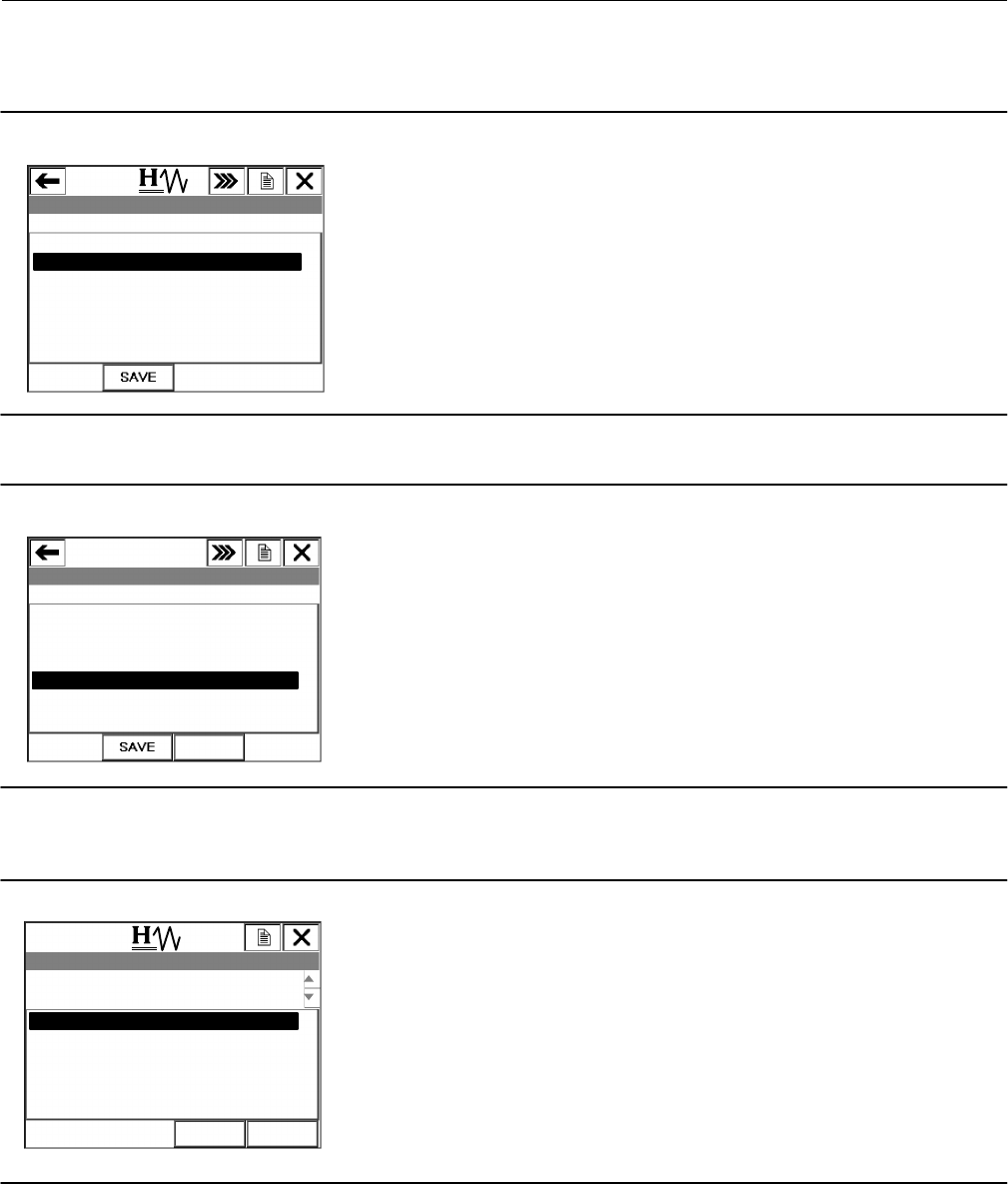
4. After selecting Partial Stroke Test you will be asked if you want to run the test using the Max Tvl Movement, as
shown in figure 3. If you select No, go to step 5. If you select Yes, go to step 8.
Figure 3. Max Tvl Movement
DVC6000: SIS
Run the test with these values?
Max Tvl Movement 10.0%
ABORT ENTER
1 Yes
2 No
Instruction Manual Supplement
D103320X012
DVC6000 SIS
January 2011
3
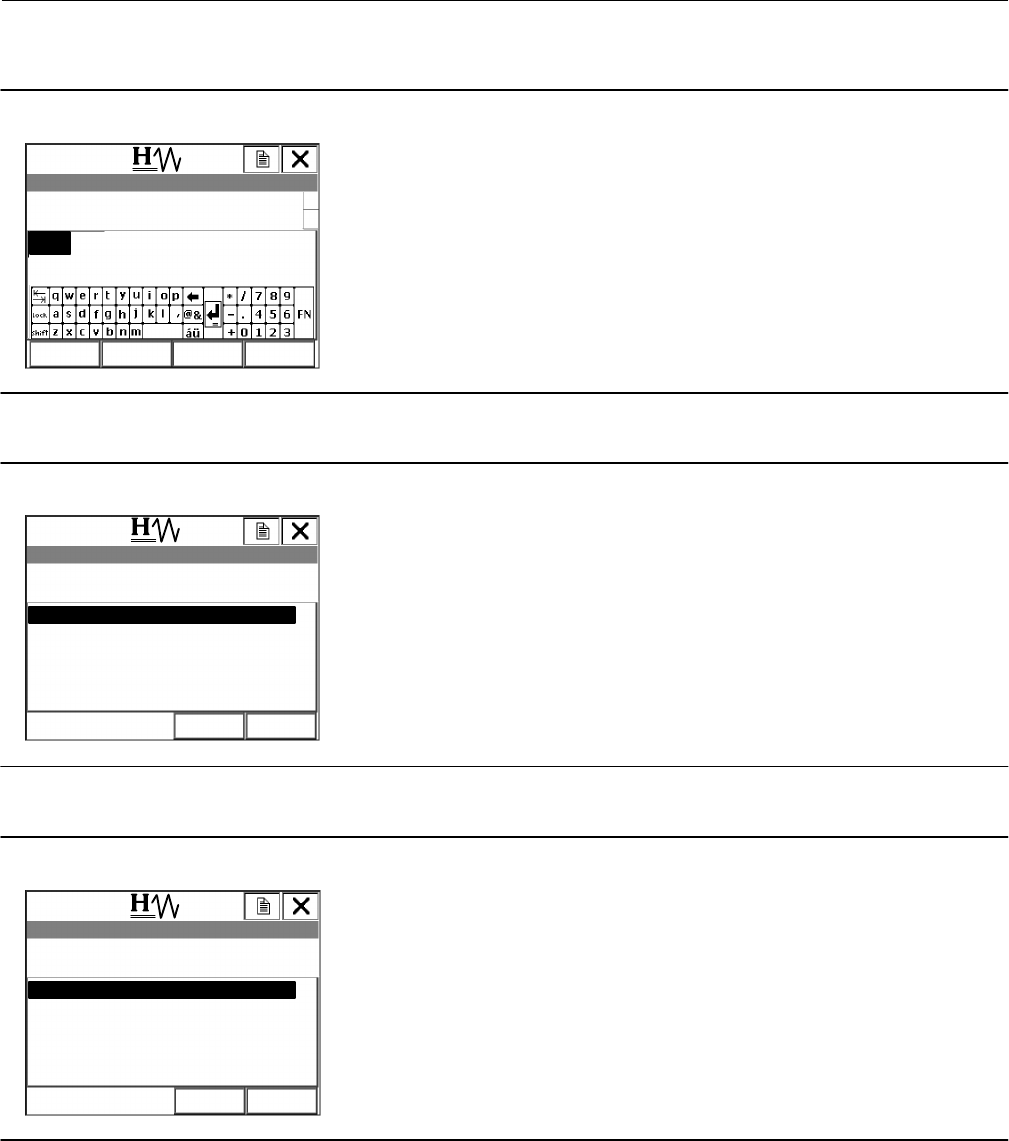
5. Enter the maximum travel movement (figure 4) desired and select ENTER.
Figure 4. Enter Max Tvl Movement
DVC6000: SIS
Max Tvl Movement 10.0%
ABORT ENTER
10.0
HELP DEL
6. Choose the desired test speed for the Partial Stroke Test, as shown in figure 5, and select ENTER
Figure 5. Select the PST Test Speed
DVC6000: SIS
Test Speed (1.0 %/sec)
ABORT ENTER
0.5 %/sec
0.25 %/sec
0.12 %/sec
0.06 %/sec
1.0 %/sec
7. Choose the desired test pause time, as shown in figure 6, and select ENTER.
Figure 6. Select the PST Pause Time
DVC6000: SIS
ABORT ENTER
Pst Pause Time (5 sec)
5 sec
10 sec
15 sec
20 sec
30 sec
Instruction Manual Supplement
D103320X012
DVC6000 SIS
January 2011
4
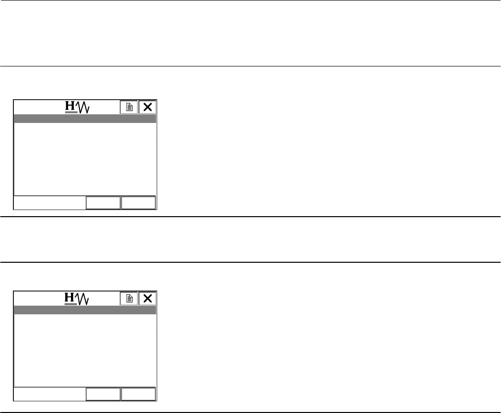
8. If there is already Partial Stroke Test data in the DVC6000 SIS, you will see the message shown in figure 7. Select OK
and go to step 9 to continue running the Partial Stroke test using the 375 Field Communicator. Select ABORT if you
want to extract the existing data using ValveLink™ Software.
Figure 7. Data not Extracted by ValveLink Software
DVC6000: SIS
There is diagnostic data in the instrument
that has not been extracted by ValveLink.
ABORT OK
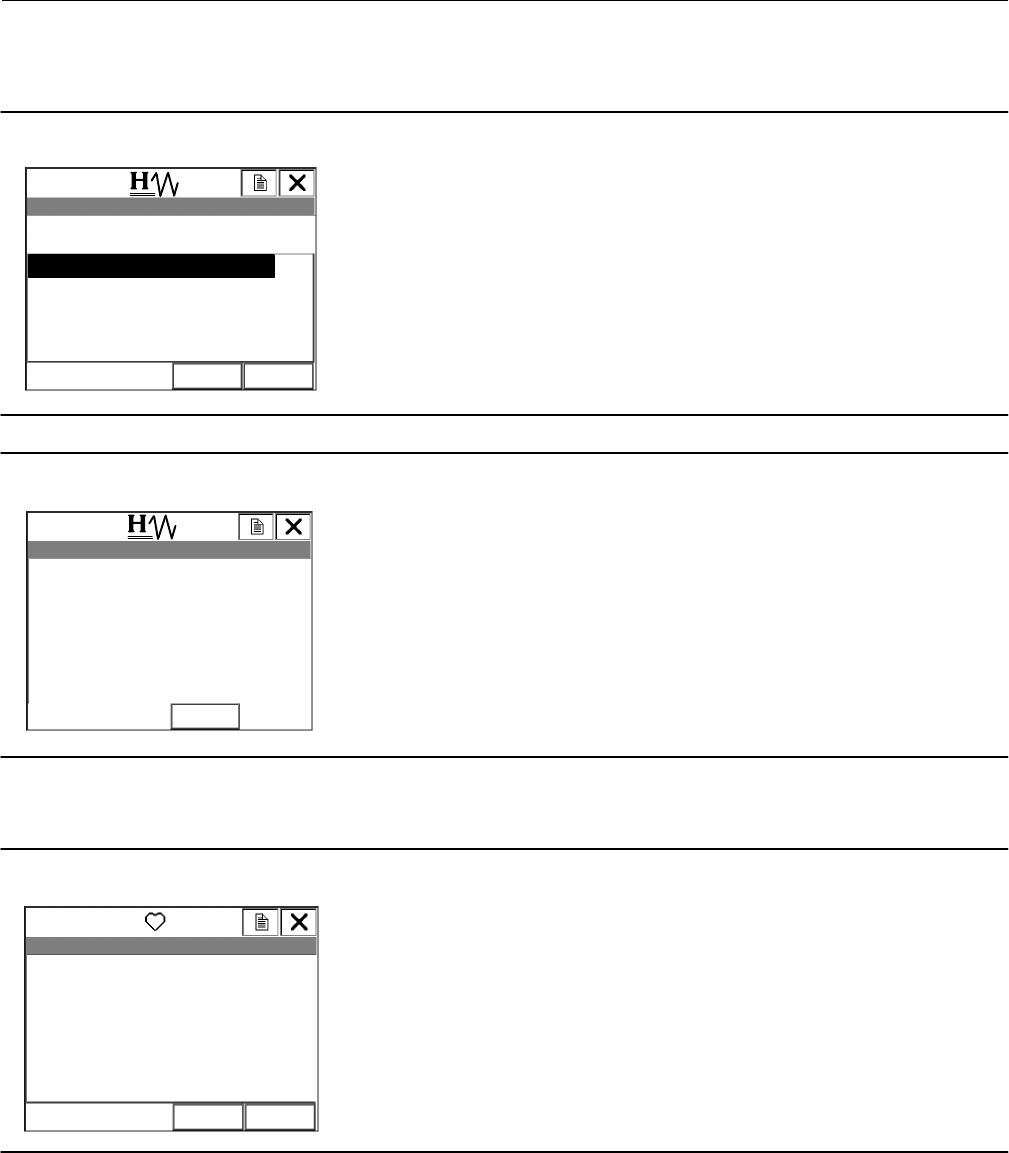
9. Select OK to confirm that you want the current Partial Stroke Test to overwrite the existing data (see figure 8) and
go to step 10. Select ABORT if you want to extract the existing data using ValveLink Software.
Figure 8. Partial Stroke Test will Overwrite Data
DVC6000: SIS
ABORT OK
Partial Stroke Test will overwrite this data.
Instruction Manual Supplement
D103320X012
DVC6000 SIS
January 2011
5
10. Choose Yes, as shown in figure 9, and select ENTER to overwrite the existing diagnostic data in the DVC6000 SIS
digital valve controller and to start the Partial Stroke Test, as shown in figure 10.
Figure 9. Overwrite Existing Data
DVC6000: SIS
1 Yes
2 No
Is it ok to overwrite the diagnostic data in
the instrument?
ABORT ENTER
Figure 10. Partial Stroke Test Initiated
DVC6000: SIS
Travel = 92.3%
ABORT
11. Once the Partial Stroke test has completed successfully, as shown in figure 11, select OK to return to the Device
Diagnostics Menu (figure 2). Select HOME to return to the Online Menu (figure 1).
Figure 11. Partial Stroke has Completed Successfully
DVC6000: SIS
Travel = 100.0%
The Partial Stroke test has completed
successfully
ABORT OK

Instruction Manual Supplement
D103320X012
DVC6000 SIS
January 2011
6
Related Documents
D Bulletin 62.1:DVC6000 SIS - Fisher FIELDVUE DVC6000 SIS Digital Valve Controllers for Safety Instrumented System
(SIS) Solutions (D102784X012)
D Fisher FIELDVUE DVC6000 SIS Digital Valve Controllers for Safety Instrumented System (SIS) Solutions Instruction
Manual (D103230X012)
D Fisher FIELDVUE DVC6000 SIS Digital Valve Controllers for Safety Instrumented System (SIS) Solutions Quick Start
Guide (D103307X012)
D Safety Manual for FIELDVUE DVC6000 Digital Valve Controllers for Safety Instrumented System (SIS) Solutions
0‐20 mA or 0‐24 VDC (D103035X012) or
D Safety Manual for FIELDVUE DVC6000 Digital Valve Controllers for Safety Instrumented System (SIS) Solutions
4‐20 mA (D103294X012)
D Pre‐Commissioning Installation / Setup Guidelines using ValveLink Software—Supplement to Fisher FIELDVUE
DVC6000 SIS Digital Valve Controllers for Safety Instrumented System (SIS) Solutions Instruction Manual
D ValveLink Software Help or Documentation
D Getting Started—475 Field Communicator (available at www.fieldcommunicator.com)
D Getting Started—375 Field Communicator (Rosemount Document 00825-0100-4276)
Note
Neither Emerson, Emerson Process Management, nor any of their affiliated entities assumes responsible for the selection, use, or
maintenance of any product. Responsibility for the selection, use, and maintenance of any product remains with the purchaser and
end‐user.
Emerson Process Management
Marshalltown, Iowa 50158 USA
Sorocaba, 18087 Brazil
Chatham, Kent ME4 4QZ UK
Dubai, United Arab Emirates
Singapore 128461 Singapore
www.Fisher.com
The contents of this publication are presented for informational purposes only, and while every effort has been made to ensure their accuracy, they are not
to be construed as warranties or guarantees, express or implied, regarding the products or services described herein or their use or applicability. All sales are
governed by our terms and conditions, which are available upon request. We reserve the right to modify or improve the designs or specifications of such
products at any time without notice. Neither Emerson, Emerson Process Management, nor any of their affiliated entities assumes responsibility for the
selection, use or maintenance of any product. Responsibility for proper selection, use, and maintenance of any product remains solely with the purchaser
and end user.
EFisher Controls International LLC 2009, 2011; All Rights Reserved
Fisher, FIELDVUE, and ValveLink are marks owned by one of the companies in the Emerson Process Management business division of Emerson Electric Co.
Emerson Process Management, Emerson, and the Emerson logo are trademarks and service marks of Emerson Electric Co. All other marks are the property
of their respective owners.
