Emerson Fisher Fieldvuedvc6200 Sis Digital Valve Controller Instruction Manual D103557X012_Jan15_AQ
2015-03-30
: Emerson Emerson-Fisher-Fieldvuedvc6200-Sis-Digital-Valve-Controller-Instruction-Manual-681757 emerson-fisher-fieldvuedvc6200-sis-digital-valve-controller-instruction-manual-681757 emerson pdf
Open the PDF directly: View PDF ![]() .
.
Page Count: 108 [warning: Documents this large are best viewed by clicking the View PDF Link!]
www.Fisher.com
Fisherr FIELDVUE™ DVC6200 SIS Digital Valve
Controller
This manual applies to
Instrument Level SIS
Device Type 130a
Device Revision 1 & 2
Hardware Revision 2
Firmware Revision 4, 5 & 6
DD Revision 3, 4 & 5
Contents
Section 1 Introduction 3.................
Installation, Pneumatic and Electrical Connections,
and Initial Configuration 3.....................
Scope of Manual 3..............................
Conventions Used in this Manual 3................
Description 3..................................
Specifications 4................................
Related Documents 7...........................
Educational Services 8...........................
Section 2 Wiring Practices 9..............
Control System Requirements 9..................
HART Filter 9.................................
Voltage Available 9............................
Compliance Voltage 10........................
Auxiliary Terminal Wiring Length Guidelines 12....
Maximum Cable Capacitance 11.................
LCP100 Control Panel 13.........................
Installaton 13.................................
Electrical Connections 13.......................
Section 3 Configuration 17...............
Guided Setup 17...............................
Manual Setup 17...............................
Mode and Protection 19........................
Instrument Mode 19.......................
Write Protection 19........................
Instrument 19................................
Identification 19...........................
Serial Numbers 20.........................
Units 20..................................
Terminal Box 20...........................
Spec Sheet 20.............................
Edit Instrument Time 20....................
X0079
Travel/Pressure Control 21......................
End Point Pressure Control 21................
Characterization 21........................
Dynamic Response 23......................
Travel Cutoffs 23..........................
Tuning 23....................................
Travel Tuning 23...........................
Integral Settings 26........................
Valve and Actuator 26..........................
SIS/Partial Stroke Test 29.......................
Partial Stroke Test (PST) 29..................
SIS Options 32............................
Outputs 32...................................
Output Terminal Configuration 32............
Switch Configuration 33....................
HART Variable Assignments 33..............
Transmitter Output 33.....................
Burst Mode 33............................
Alert Setup 34.................................
Change to HART 5 / HART 7 36....................
Instruction Manual
D103557X012
DVC6200 SIS Digital Valve Controller
January 2015

Instruction Manual
D103557X012
DVC6200 SIS Digital Valve Controller
January 2015
2
Contents (continued)
Section 4 Calibration 37.................
Calibration Overview 37.........................
Travel Calibration 38...........................
Auto Calibration 38........................
Manual Calibration 39......................
Pushbutton Calibration 40..................
Sensor Calibration 41..........................
Pressure Sensors 41........................
Analog Input Calibration 42.................
Relay Adjustment 43...........................
Double‐Acting Relay 43.....................
Single‐Acting Relays 44.....................
PST Calibration 45.............................
Section 5 Device Information,
Diagnostics, and Alerts 47...............
Overview 47...................................
Status & Primary Purpose Variables 47............
Device Information 47.........................
Service Tools 48................................
Device Status 48..............................
Alert Record 48...............................
Electronics 48.............................
Pressure 50...............................
Travel 50.................................
Travel History 51..........................
Alert Record 52............................
Status 52.................................
Diagnostics 53................................
Stroke Valve 53............................
Partial Stroke Test 53.......................
Demand Mode Tests 55.....................
Solenoid Valve Health Monitoring 57.........
Variables 57...................................
Section 6 Maintenance and
Troubleshooting 59.....................
Replacing the Magnetic Feedback Assembly 60......
Module Base Maintenance 60.....................
Tools Required 60.............................
Component Replacement 61....................
Removing the Module Base 61..................
Replacing the Module Base 62...................
Submodule Maintenance 62......................
I/P Converter 63...............................
Printed Wiring Board (PWB) Assembly 65..........
Pneumatic Relay 66............................
Gauges, Pipe Plugs or Tire Valves 67..............
Terminal Box 67................................
Removing the Terminal Box 68..................
Replacing the Terminal Box 68...................
Troubleshooting 69.............................
Checking Voltage Available 69....................
Restart Processor 69............................
DVC6200 SIS Technical Support Checklist 72........
Section 7 Parts 73......................
Parts Ordering 73...............................
Parts Kits 73...................................
PWB Assembly 73.............................
Parts List 74...................................
Housing 74...................................
Common Parts 75.............................
Module Base 75...............................
I/P Converter Assembly 75......................
Relay 75.....................................
Terminal Box 75...............................
Feedback Connection Terminal Box 75............
Pressure Gauges, Pipe Plugs, or Tire
Valve Assemblies 76.........................
DVC6215 Feedback Unit 76.....................
HART Filter 76................................
Line Conditioner 76............................
Appendix A Principle of Operation 83......
HART Communication 83........................
DVC6200 SIS Digital Valve Controller 83............
Appendix B Field Communicator
Menu Tree 87........................
Glossary 95............................
Index 101.............................
The FIELDVUE DVC6200 SIS Digital Valve Controller is a core component of the PlantWeb™ digital
plant architecture. The digital valve controller powers PlantWeb by capturing and delivering valve
diagnostic data. Coupled with ValveLink™ software, the DVC6200 SIS provides users with an accurate
picture of valve performance, including actual stem position, instrument input signal, and pneumatic
pressure to the actuator. Using this information, the digital valve controller diagnoses not only itself,
but also the valve and actuator to which it is mounted.
Instruction Manual
D103557X012
Introduction
January 2015
3
Section 1 Introduction
Installation, Pneumatic and Electrical Connections,
and Initial Configuration
Refer to the DVC6200 Series Quick Start Guide (D103556X012) for DVC6200 SIS
installation, connection, and initial configuration information. If a copy of this quick
start guide is needed scan or click the QR code at the right, contact your Emerson
Process Management sales office, or visit our website at www.Fisher.com.
Scope of Manual
This instruction manual is a supplement to the DVC6200 Series Quick Start Guide (D103556X012) and safety manual
(D103601X012) that ship with every instrument. This instruction manual includes product specifications, reference
materials, custom setup information, maintenance procedures, and replacement part details.
This instruction manual describes using the 475 Field Communicator to set up and calibrate the instrument. You can
also use Fisher ValveLink software to setup, calibrate, and diagnose the valve and instrument. For information on using
ValveLink software with the instrument refer to ValveLink software help or documentation.
Do not install, operate, or maintain a DVC6200 SIS digital valve controller without being fully trained and qualified in
valve, actuator, and accessory installation, operation, and maintenance. To avoid personal injury or property damage,
it is important to carefully read, understand, and follow all of the contents of this manual, including all safety cautions
and warnings. If you have any questions about these instructions, contact your Emerson Process Management sales
office before proceeding.
Conventions Used in this Manual
Navigation paths and fast‐key sequences are included for procedures and parameters that can be accessed using the
Field Communicator.
For example, to access Device Setup:
Field Communicator Configure > Guided Setup > Device Setup (2‐1‐1)
Refer to Appendix B for Field Communicator menu trees.
Description
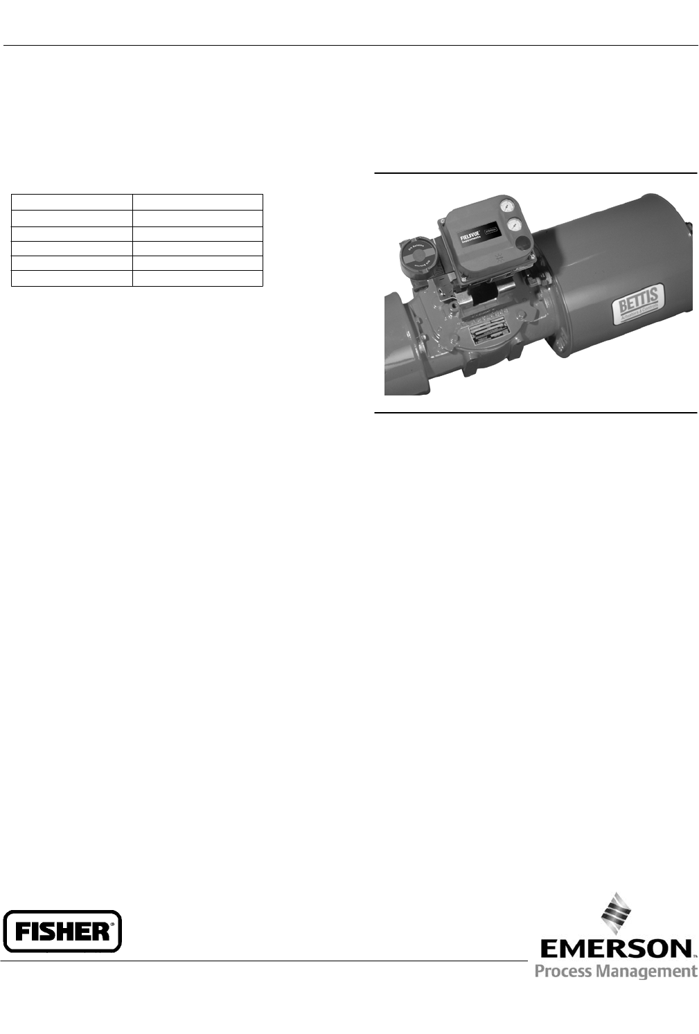
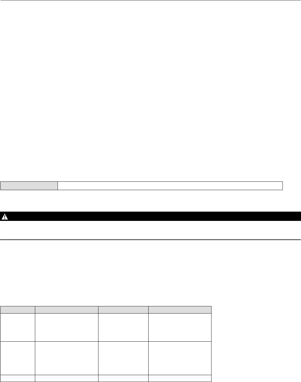
DVC6200 SIS digital valve controllers (figure 1‐1) are HART communicating, microprocessorbased
currenttopneumatic instruments. The DVC6200 SIS digital valve controller has three fundamental functions.
1. Modulate a pneumatic output to a valve actuator in response to a demand signal from a logic solver to move the
valve to a safe state.
2. Perform periodic tests on a valve assembly to exercise the mechanical components that are prone to sticking.
3. Continuously monitor the health of the valve and report alerts.
Scan or click
to access
field support

Instruction Manual
D103557X012
Introduction
January 2015
4
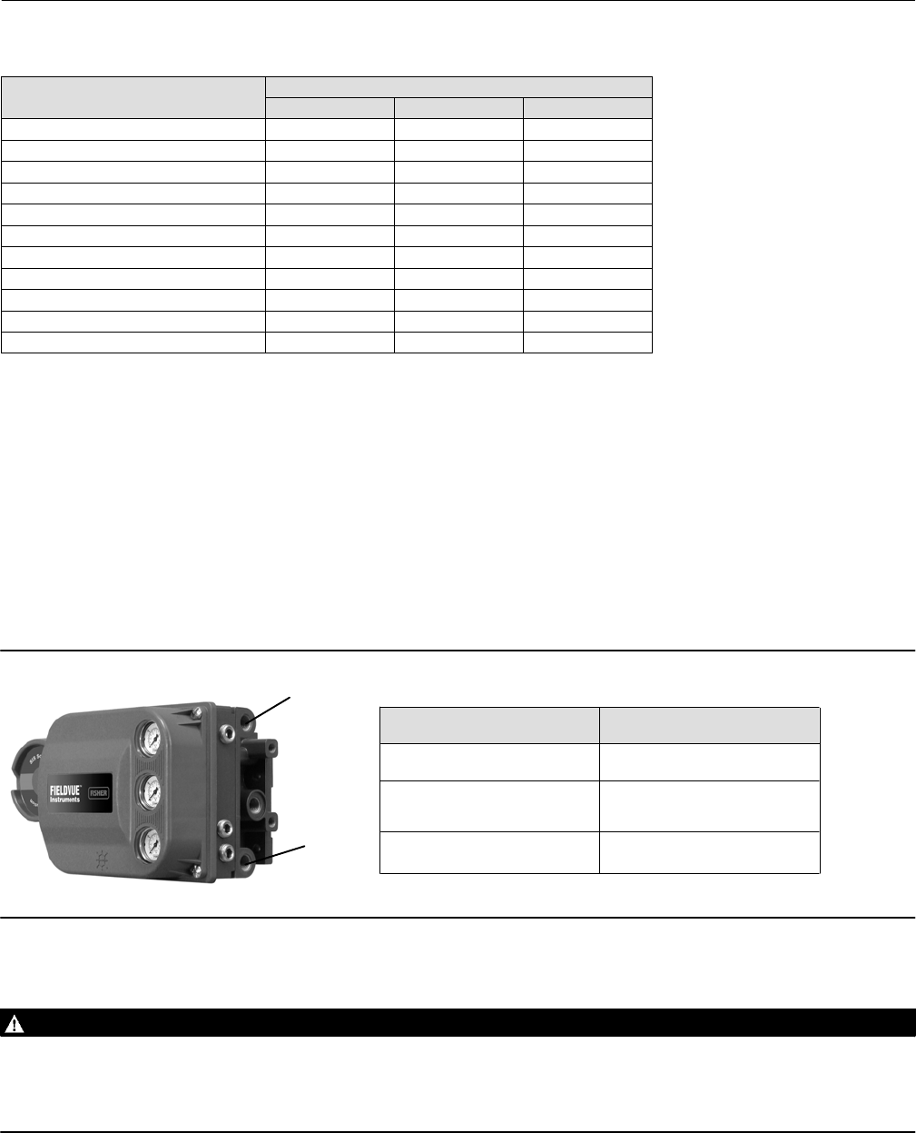
Figure 1‐1. FIELDVUE DVC6200 SIS Digital Valve Controller Mounted on a Bettis Quarter-Turn Actuator
X0079
Specifications
WARNING
Refer to table 1‐1 for specifications. Incorrect configuration of a positioning instrument could result in the malfunction of
the product, property damage or personal injury.
Specifications for DVC6200 SIS digital valve controllers are shown in table 1‐1. Specifications for the Field
Communicator can be found in the product manual for the Field Communicator.

Instruction Manual
D103557X012
Introduction
January 2015
5
Table 1‐1. Specifications
Available Mounting
J Sliding‐stem linear applications
J Quarter‐turn rotary applications
J Integral mounting to Fisher rotary actuators
J Integral mounting to the Fisher GX control valve
and actuator system
DVC6200 SIS digital valve controllers can also be
mounted on other actuators that comply with
IEC 60534‐6‐1, IEC 60534‐6‐2, VDI/VDE‐3845, and
NAMUR mounting standards
Mounting the instrument vertically, with the vent at
the bottom of the assembly, or horizontally, with the
vent pointing down, is recommended to allow
drainage of moisture that may be introduced via the
instrument air supply
Communication Protocol
JHART 5 or JHART 7
Input Signal
Point-to-Point
Analog Input Signal: 4‐20 mA DC, nominal
Minimum Voltage Available at Instrument Terminals
must be 9.5 VDC for analog control, 10 VDC for HART
communication
Minimum Control Current: 4.0 mA
Minimum Current w/o Microprocessor Restart: 3.5 mA
Maximum Voltage: 30 VDC
Overcurrent protected
Reverse Polarity protected
Multi-Drop
Instrument Power: 11 to 30 VDC at 10 mA
Reverse Polarity protected
Supply Pressure(1)
Minimum Recommended: 0.3 bar (5 psig) higher
than maximum actuator requirements
Maximum: 10.0 bar (145 psig) or maximum pressure
rating of the actuator, whichever is lower
Medium: Air or Natural Gas
Air: Supply pressure must be clean, dry air that meets
the requirements of ISA Standard 7.0.01.
Natural Gas: Natural Gas must be clean, dry, oil-free
and noncorrosive. H2S content should not exceed 20
ppm.
A maximum 40 micrometer particle size in the air
system is acceptable. Further filtration down to 5
micrometer particle size is recommended. Lubricant
content is not to exceed 1 ppm weight (w/w) or
volume (v/v) basis. Condensation in the air supply
should be minimized
Per ISO 8573-1
Maximum particle density size: Class 7
Oil content: Class 3
Pressure Dew Point: Class 3 or at least 10 K less than
the lowest ambient temperature expected
Output Signal
Pneumatic Output: up to full supply pressure
Minimum Span: 0.4 bar (6 psig)
Maximum Span: 9.5 bar (140 psig)
Action: Double, Single Direct, or Single Reverse
Electronic Output(2)
J Integral 4‐20 mA Position Transmitter:
4‐20 mA output, isolated
Supply Voltage: 8‐30 VDC
Fault Indication: offrange high or low
Reference Accuracy: 1% of travel span
Safety Accuracy: 5% of travel span
J Integral Switch:
One isolated switch, configurable throughout the
calibrated travel range or actuated from a device
alert
Off State: 0 mA (nominal)
On State: up to 1 A
Supply Voltage: 30 VDC maximum
Reference Accuracy: 2% of travel span
Safety Accuracy: 5% of travel span
Steady State Air Consumption(3)(4)
Low Bleed Relay
At 1.4 bar (20 psig) supply pressure:
0.056 normal m3/hr (2.1 scfh), average
At 5.5 bar (80 psig) supply pressure:
0.184 normal m3/hr (6.9 scfh), average
Maximum Output Capacity(3)(4)
At 1.4 bar (20 psig) supply pressure:
10.0 normal m3/hr (375 scfh)
At 5.5 bar (80 psig) supply pressure:
29.5 normal m3/hr (1100 scfh)
Operating Ambient Temperature Limits(1)(5)
-52 to 85_C (-62 to 185_F)
Independent Linearity(6)
Typical Value: +/-0.50% of output span
‐continued‐

Instruction Manual
D103557X012
Introduction
January 2015
6
Table 1‐1. Specifications (continued)
Electromagnetic Compatibility
Meets EN 61326‐1 (First Edition)
Immunity‐Industrial locations per Table 2 of the
EN 61326‐1 standard. Performance is
shown in table 1‐2 below.
Emissions-Class A
ISM equipment rating: Group 1, Class A
Vibration Testing Method
Tested per ANSI/ISA S75.13.01 Section 5.3.5
Input Load Impedance
An equivalent impedance of 500 ohms may be used.
This value corresponds to 10V @ 20 mA.
Humidity Testing Method
Tested per IEC 61514‐2
Electrical Classification
Hazardous Area Approvals
CSA— Intrinsically Safe, Explosion-proof, Division 2,
Dust Ignition-proof
FM— Intrinsically Safe, Explosion-proof, Dust
Ignition-proof, Non-Incendive
ATEX— Intrinsically Safe, Flameproof, Type n
IECEx— Intrinsically Safe, Flameproof, Type n
Auxiliary Terminal Contact: Nominal Electrical
Rating 5 V, <1 mA; It is recommended that the
switch be sealed or have gold plated contacts to
avoid corrosion
Electrical Housing
CSA— Type 4X, IP66
FM— Type 4X, IP66
ATEX— IP66
IECEx— IP66
Other Classifications/Certifications
CUTR— Customs Union Technical Regulations
(Russia, Kazakhstan and Belarus)
INMETRO— National Institute of Metrology, Quality,
and Technology (Brazil)
PESO CCOE— Petroleum and Explosives Safety
Organisation - Chief Controller of Explosives (India)
Contact your Emerson Process Management sales
office for classification/certification specific
information.
IEC 61010 Compliance Requirements
Power Source: The loop current must be derived from
a separated extra‐low voltage (SELV) power source
Environmental Conditions: Installation Category I
Connections
Supply Pressure: 1/4 NPT internal and integral pad for
mounting Fisher 67CFR regulator
Output Pressure: 1/4 NPT internal
Tubing: 3/8‐inch recommended
Vent: 3/8 NPT internal
Electrical: 1/2 NPT internal, M20 adapter optional
Actuator Compatibility
Stem Travel (Sliding-Stem Linear)
Minimum: 6.5 mm (0.25 inch)
Maximum: 606 mm (23.875 inches)
Shaft Rotation (Quarter-Turn Rotary)
Minimum: 45_
Maximum: 90_
Weight
DVC6200 SIS
Aluminum: 3.5 kg (7.7 lbs)
Stainless Steel: 8.6 kg (19 lbs)
DVC6205 SIS: 4.1 kg (9 lbs)
DVC6215: 1.4 kg (3.1 lbs)
Construction Materials
Housing, module base, and terminal box:
A03600 low copper aluminum alloy (standard)
Stainless steel (optional)
Cover: Thermoplastic polyester
Elastomers: Fluorosilicone
Options
J Supply and output pressure gauges or tire valves
J Integral mounted filter regulator J Energize to trip
J Standard Bleed Relay J Beacon indicator J Remote
mount(7)(8) J LCP100 local control panel J Fisher
LC340 line conditioner J Stainless steel
NOTE: Specialized instrument terms are defined in ANSI/ISA Standard 51.1 – Process Instrument Terminology.
1. The pressure/temperature limits in this document and any other applicable code or standard should not be exceeded.
2. The electronic output is available with either the position transmitter or the switch.
3. Normal m3/hour – Normal cubic meters per hour at 0_C and 1.01325 bar, absolute. Scfh – Standard cubic feet per hour at 60_F and 14.7 psia.
4. Values at 1.4 bar (20 psig) based on single‐acting direct relay; values at 5.5 bar (80 psig) based on double‐acting relay.
5. Temperature limits vary based on hazardous area approval.
6. Not applicable for travels less than 19 mm (0.75 inch) or for shaft rotation less than 60 degrees. Also not applicable for digital valve controllers in long-stroke applications over 4-inch.
7. 4‐conductor shielded cable, 18 to 22 AWG minimum wire size, in rigid or flexible metal conduit, is required for connection between base unit and feedback unit. Pneumatic tubing between base
unit output connection and actuator has been tested to 91 meters (300 feet). At 15 meters (50 feet) there was no performance degradation. At 91 meters there was minimal pneumatic lag.
8. The position monitor (transmitter or switch) with the remote mount construction is not safety certified.

Instruction Manual
D103557X012
Introduction
January 2015
7
Table 1‐2. EMC Summary Results—Immunity
Port Phenomenon Basic Standard Test Level Performance
Criteria(1)
Enclosure
Electrostatic discharge (ESD) IEC 61000‐4‐2 4 kV contact
8 kV air A
Radiated EM field IEC 61000‐4‐3
80 to 1000 MHz @ 10V/m with 1 kHz AM at 80%
1400 to 2000 MHz @ 3V/m with 1 kHz AM at 80%
2000 to 2700 MHz @ 1V/m with 1 kHz AM at 80%
A
Rated power frequency
magnetic field IEC 61000‐4‐8 30 A/m at 50/60Hz A
I/O signal/control
Burst IEC 61000‐4‐4 1 kV A
Surge IEC 61000‐4‐5 1 kV B
Conducted RF IEC 61000‐4‐6 150 kHz to 80 MHz at 3 Vrms A
Performance criteria: +/- 1% effect.
1. A = No degradation during testing. B = Temporary degradation during testing, but is self‐recovering.
Related Documents
This section lists other documents containing information related to the DVC6200 SIS digital valve controller. These
documents include:
D Bulletin 62.1:DVC6200 SIS - Fisher FIELDVUE DVC6200 SIS Digital Valve Controller (D103555X012)
D Bulletin 62.1:DVC6200(S1) Fisher FIELDVUE DVC6200 Digital Valve Controller Dimensions (D103543X012)
D Fisher FIELDVUE DVC6200 Series Digital Valve Controller Quick Start Guide (D103556X012)
D FIELDVUE DVC6200 SIS Safety Manual (D103601X012)
D HART Field Device Specification for FIELDVUE DVC6200 SIS (D103638X012)
D Partial Stroke Test using 475/375 Field Communicator (D103320X012)
D Partial Stroke Test using ValveLink Software (D103274X012)
D Pre-Commissioning Installation / Setup Guidelines using ValveLink Software (D103285X012)
D Bulletin 62.1:LCP100 (D103604X012)
D Fisher LCP100 Instruction Manual (D103272X012)
D Fisher LC340 Instruction Manual (D102797X012)
D Fisher HF340 Filter Instruction Manual (D102796X012)
D 475 Field Communicator User's Manual
D ValveLink Software Help or Documentation
All documents are available from your Emerson Process Management sales office. Also visit our website at
www.FIELDVUE.com.

Instruction Manual
D103557X012
Introduction
January 2015
8
Educational Services
For information on available courses for the DVC6200 SIS digital valve controller, as well as a variety of other products,
contact:
Emerson Process Management
Educational Services - Registration
Phone: +1-641‐754‐3771 or +1-800‐338‐8158
E‐mail: education@emerson.com
http://www.emersonprocess.com/education

Instruction Manual
D103557X012
Wiring Practices
January 2015
9
Section 2 Wiring Practices22
Logic Solver or Control System Requirements
There are several parameters that should be checked to ensure the logic solver or control system is compatible with
the DVC6200 SIS digital valve controller.
HART Filter / Line Conditioner
Depending on the logic solver or control system and operational mode of the DVC6200 SIS digital valve controller, a
line conditioner or HART filter may be required.
Operational Mode Control System
or Logic Solver
HART Filter
Required?
Line Conditioner
Required?
4-20 mA
Point-to-Point Loop
PROVOX™, RS3™,
DeltaV™, Ovation™ No No
All Others Consult Sales Office No
24 VDC
Multi-Drop Loop All No Yes
The HF340 HART filter and LC340 Line Conditioner are passive devices that are inserted in the field wiring of the HART
loop. A filter or line conditioner is normally installed near the field wiring terminals of the system I/O (see figure 2‐1).
Its purpose is to effectively isolate the system output from modulated HART communication signals and raise the
impedance of the system to allow HART communication. For more information, refer to the HF340 HART filter
(D102796X012) or LC340 Line Conditioner (D102797X012) instruction manual.
Voltage Available
The voltage available at the DVC6200 SIS digital valve controller must be at least 10 VDC. The voltage available at the
instrument is not the actual voltage measured at the instrument when the instrument is connected. The voltage
measured at the instrument is limited by the instrument and is typically less than the voltage available.
As shown in figure 2‐1, the voltage available at the instrument depends upon:
D The logic solver or control system compliance voltage
D if a line conditioner filter or intrinsic safety barrier is used, and
D the wire type and length.
The compliance voltage is the maximum voltage at the logic solver or control system output terminals at which the
system can produce maximum loop current.
The voltage available at the instrument may be calculated from the following equation:
Voltage Available = [Compliance Voltage (at maximum current)] - [line conditioner/filter voltage drop] - [total cable
resistance maximum current] - [barrier resistance x maximum current].
The calculated voltage available should be greater than or equal to 10 volts DC.

Instruction Manual
D103557X012
Wiring Practices
January 2015
10
Figure 2‐1. Determining Voltage Available at the Instrument
The voltage available at the instrument is not the voltage measured at the instrument terminals. Once the instrument is
connected, the instrument limits the measured voltage to approximately 8.0 to 9.5 volts.
Obtain filter voltage drop. The measured drop will be different than this value. The measured filter voltage drop
depends upon control system output voltage, the intrinsic safety barrier (if used), and the instrument. See note 2.
LINE CONDITIONER
OR HART FILTER
(if used)
CONTROL
SYSTEM
+
-
COMPLIANCE VOLTAGE
VOLTAGE
AVAILABLE AT THE
INSTRUMENT
+
-
R
INTRINSIC SAFETY
BARRIER
(if used)
Logic solver or control system compliance voltage
= Voltage available at the instrument
– Line conditioner or filter voltage drop (if used)
Example Calculation
18.5 volts (at 21.05 mA for Honeywell TDC2000)
– 2 volts
– Intrinsic safety barrier resistance (if used) x maximum loop current – 2.55 volts (121 ohms x 0.02105 amps)
TOTAL LOOP
CABLE RESISTANCE
– Total loop cable resistance x maximum loop current – 1.01 volts (48 ohms x 0.02105 amps for
1000 feet of Belden 9501 cable)
= 15.49 volts, available—if safety barrier (2.55 volts)
is not used
1
2
NOTES:
1
2
Calculate Voltage Available at the Instrument as follows:
Compliance Voltage
If the compliance voltage of the logic solver or control system is not known, perform the following compliance voltage
test.
1. Disconnect the field wiring from the system and connect equipment as shown in figure 2‐2 to the system terminals.
Figure 2‐2. Voltage Test Schematic
CIRCUIT
UNDER
TEST
VOLTMETER
MILLIAMMETER
1 kW POTENTIOMETER
A6192‐1

Instruction Manual
D103557X012
Wiring Practices
January 2015
11
2. Set the system to provide maximum output current.
3. Increase the resistance of the 1 kW potentiometer, shown in figure 2‐2, until the current observed on the
milliammeter begins to drop quickly.
4. Record the voltage shown on the voltmeter. This is the compliance voltage.
For specific parameter information relating to your control system, contact your Emerson Process Management sales
office.
Maximum Cable Capacitance
The maximum cable length for HART communication is limited by the characteristic capacitance of the cable.
Maximum length due to capacitance can be calculated using the following formulas:
Length(ft) = [160,000 - Cmaster(pF)] [Ccable(pF/ft)]
Length(m) = [160,000 - Cmaster(pF)] [Ccable(pF/m)]
where:
160,000 = a constant derived for FIELDVUE instruments to ensure that the HART network RC time constant will be no
greater than 65 μs (per the HART specification).
Cmaster = the capacitance of the control system or HART filter
Ccable = the capacitance of the cable used (see table 2‐1)
The following example shows how to calculate the cable length for a Foxborot I/A control system (1988) with a Cmaster
of 50, 000 pF and a Belden 9501 cable with characteristic capacitance of 50pF/ft.
Length(ft) = [160,000 - 50,000pF] [50pF/ft]
Length = 2200 ft.
The HART communication cable length is limited by the cable characteristic capacitance. To increase cable length,
select a wire with lower capacitance per foot. Contact your Emerson Process Management sales office for specific
information relating to your control system.
Table 2‐1. Cable Characteristics
Cable Type Capacitance(1)
pF/Ft
Capacitance(1)
pF/m
Resistance(2)
Ohms/ft
Resistance(2)
Ohms/m
BS5308/1, 0.5 sq mm 61.0 200 0.022 0.074
BS5308/1, 1.0 sq mm 61.0 200 0.012 0.037
BS5308/1, 1.5 sq mm 61.0 200 0.008 0.025
BS5308/2, 0.5 sq mm 121.9 400 0.022 0.074
BS5308/2, 0.75 sq mm 121.9 400 0.016 0.053
BS5308/2, 1.5 sq mm 121.9 400 0.008 0.025
BELDEN 8303, 22 awg 63.0 206.7 0.030 0.098
BELDEN 8441, 22 awg 83.2 273 0.030 0.098
BELDEN 8767, 22 awg 76.8 252 0.030 0.098
BELDEN 8777, 22 awg 54.9 180 0.030 0.098
BELDEN 9501, 24 awg 50.0 164 0.048 0.157
BELDEN 9680, 24 awg 27.5 90.2 0.048 0.157
BELDEN 9729, 24 awg 22.1 72.5 0.048 0.157
BELDEN 9773, 18 awg 54.9 180 0.012 0.042
BELDEN 9829, 24 awg 27.1 88.9 0.048 0.157
BELDEN 9873, 20 awg 54.9 180 0.020 0.069
1. The capacitance values represent capacitance from one conductor to all other conductors and shield. This is the appropriate value to use in the cable length calculations.
2. The resistance values include both wires of the twisted pair.

Instruction Manual
D103557X012
Wiring Practices
January 2015
12
Auxiliary Terminal Wiring Length Guidelines
The Auxiliary Input Terminals of a DVC6200 SIS can be used with an LCP100 local control panel or a locally‐mounted
switch for initiating a partial stroke test. Some applications require that the switch or local control panel be installed
remotely from the DVC6200 SIS.
The length for wiring connected to the Auxiliary Input Terminals is limited by capacitance. For proper operation of the
Auxiliary Input Terminals capacitance should not exceed 100,000 pF. As with all control signal wiring, good wiring
practices should be observed to minimize adverse effect of electrical noise on the Aux Switch function.
Example Calculation: Capacitance per foot or per meter is required to calculate the length of wire that may be
connected to the Aux switch input. The wire should not exceed the capacitance limit of 100,000 pF. Typically the wire
manufacturer supplies a data sheet which provides all of the electrical properties of the wire. The pertinent parameter
is the highest possible capacitance. If shielded wire is used, the appropriate number is the “Conductor to Other
Conductor & Shield” value.
Example — 18AWG Unshielded Audio, Control and Instrumentation Cable
Manufacturer's specifications include:
Nom. Capacitance Conductor to Conductor @ 1 KHz: 26 pF/ft
Nom. Conductor DC Resistance @ 20 Deg. C: 5.96 Ohms/1000 ft
Max. Operating Voltage - UL 200 V RMS (PLTC, CMG),150 V RMS (ITC)
Allowable Length with this cable = 100,000pF /(26pF/ft) =3846 ft
Example — 18AWG Shielded Audio, Control and Instrumentation Cable
Manufacturer's specifications include:
Nom. Characteristic Impedance: 29 Ohms
Nom. Inductance: .15 μH/ft
Nom. Capacitance Conductor to Conductor @ 1 KHz: 51 pF/ft
Nom. Cap. Cond. to other Cond. & Shield @ 1 KHz 97 pF/ft
Allowable Length with this cable = 100,000pF /(97pF/ft) = 1030 ft
The AUX switch input passes less than 1 mA through the switch contacts, and uses less than 5 V, therefore, neither the
resistance nor the voltage rating of the cable are critical. Ensure that switch contact corrosion is prevented. It is
generally advisable that the switch have gold‐plated or sealed contacts.

Instruction Manual
D103557X012
Wiring Practices
January 2015
13
LCP100 Local Control Panel
Installation
The Fisher LCP100 Local Control Panel has four (4) mounting holes for on‐site mounting of the device. The LCP100
must be installed so that the wiring connections are on the bottom to prevent accumulation of moisture inside the
box.
Electrical Connections
WARNING
Select wiring and/or cable glands that are rated for the environment of use (such as hazardous location, ingress protection,
and temperature). Failure to use properly rated wiring and/or cable glands can result in personal injury or property damage
from fire or explosion.
Wiring connections must be in accordance with local, regional, and national codes for any given hazardous area approval.
Failure to follow the local, regional, and national codes could result in personal injury or property damage from fire or
explosion.
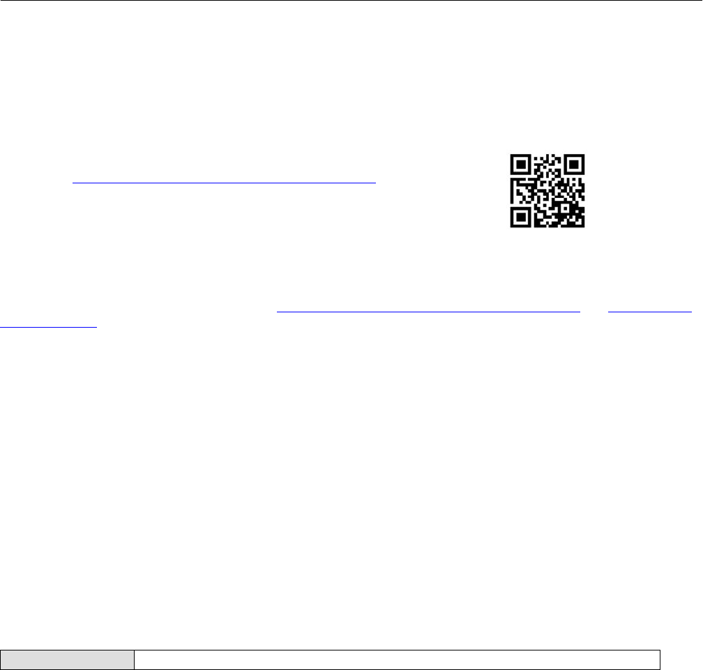
Electrical connections are shown in figures 2‐3, 2‐4, and 2‐5. There are two different methods to power the LCP100.
Method one requires an external 24 VDC source to power the LCP100. Method two uses loop power wiring in series.
In method one, shown in figure 2‐3, signal wiring is brought to the enclosure through a 3/4 NPT or M20 housing
conduit connection (connection type is identified on nameplate.
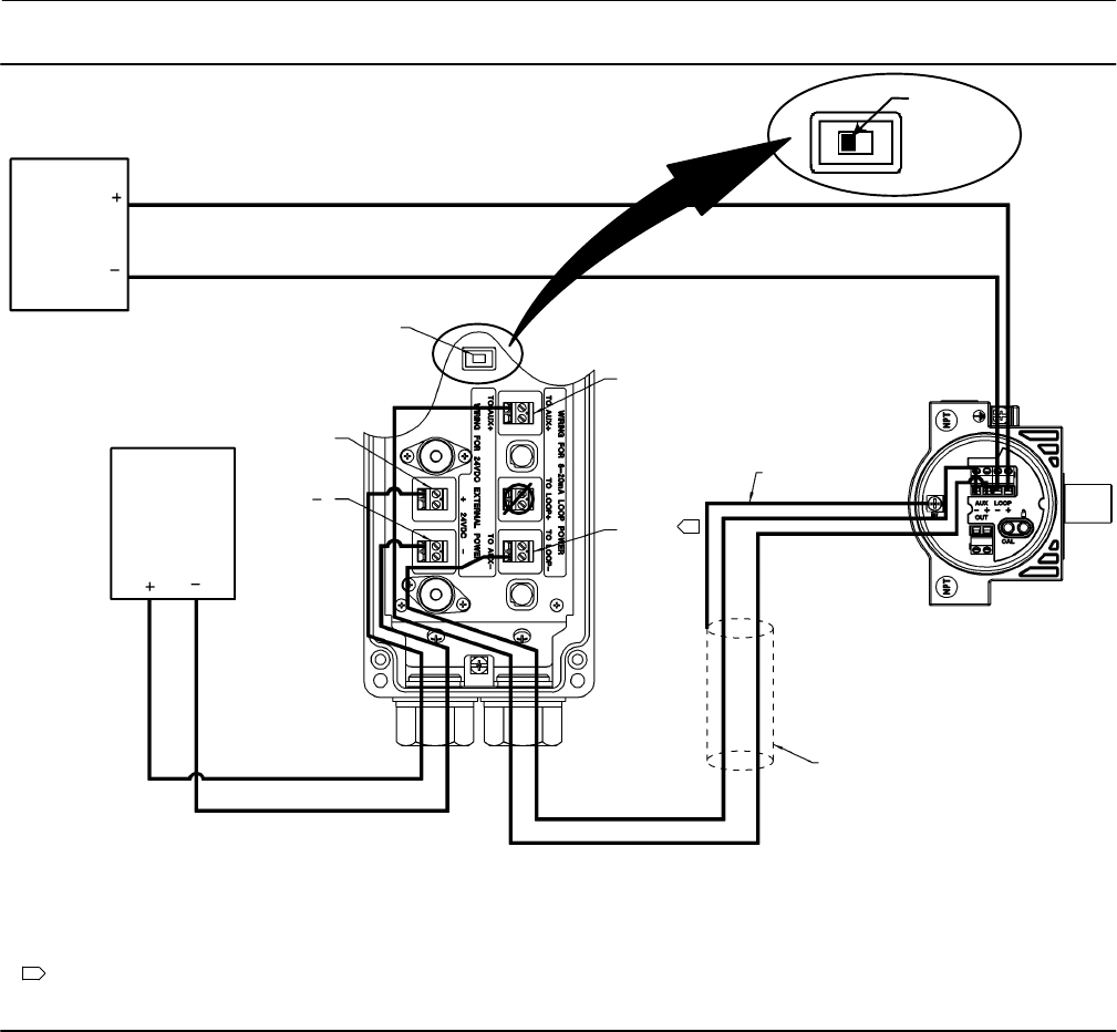
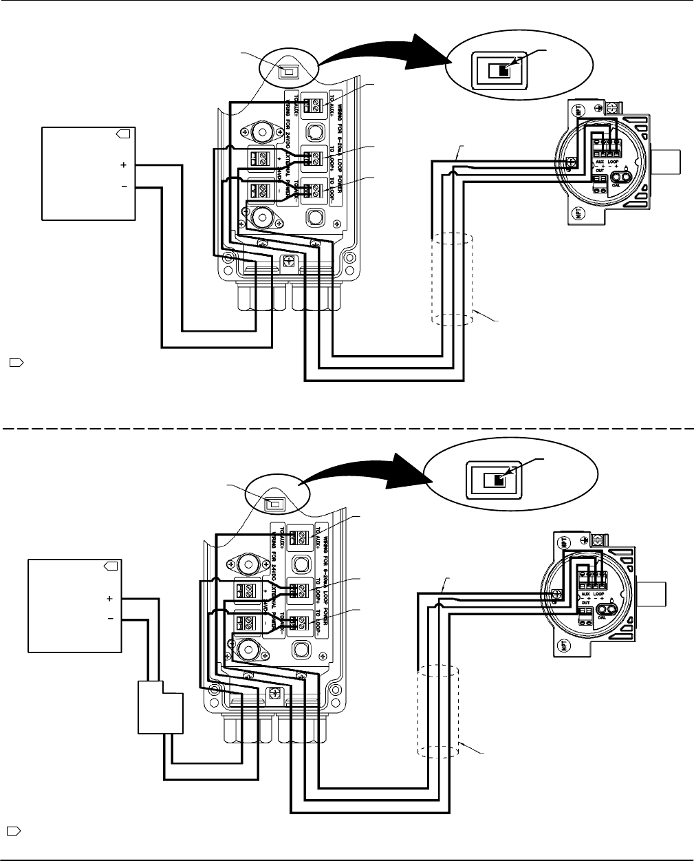
Method two can be accomplished in two ways; with the wiring going first to the LCP100, then to the DVC6200 SIS, as
shown in in figure 2‐4, or with the wiring going first to the DVC6200 SIS, then to the LCP100, as shown in figure 2‐5.
However, because the LCP100 does consume energy to drive the push buttons and lights, the minimum current signal
from the logic solver must be 8 mA. If the logic solver cannot provide an output range of 8‐20 mA, then method one
must be used.
When connections are complete move the DIP switch to the appropriate power setting. If external 24 VDC is used to
power the LCP100, make sure the switch is on the side that says “24VDC”. If loop power is used, slide the switch to the
side that says “LOOP”.
Note
Factory default for the DIP switch power selector is 24VDC.
When installing the cover tighten the screws evenly in a criss‐cross pattern to help ensure the cover is properly
installed.
Instruction Manual
D103557X012
Wiring Practices
January 2015
14
Figure 2‐3. Wiring for 24 VDC External Power Configuration
NOTE: DO NOT CONNECT THE LOOP + TERMINAL IN THE LCP100 TO THE LOOP + TERMINAL IN THE DVC6200 SIS.
THIS WILL CAUSE THE LCP100 TO UNNECESSARILY CONSUME 4 mA AT THE EXPENSE OF THE DVC6200 SIS.
SIMPLE METHOD FOR INSTALLING AN LCP100 TO AN EXISTING
DVC6200 SIS INSTRUMENT WHEN 24 VDC POWER IS AVAILABLE
SWITCH TO
24VDC POSITION
24 VDC
(USER SUPPLIED)
4‐20 mA
AUX )
AUX*
CASE GROUND
SHIELD NOT CONNECTED TO LCP100
24VDC )
DVC6200 SIS TERMINAL BOX
LCP100
SOURCE
24VDC *
1
1 THIS CONNECTION IS ALSO LABELED LOOP -.
LOGIC
SOLVER
OUTPUT
24VDC
(USER SUPPLIED)
E1465
Instruction Manual
D103557X012
Wiring Practices
January 2015
15
Figure 2‐4. Wiring for Loop‐Powered Configuration; Logic Solver Wired to the Fisher LCP100 then the
FIELDVUE DVC6200 SIS
NOTE:
1 THE LOGIC SOLVER MINIMUM
OUTPUT MUST BE AT LEAST 8 mA. THE
LCP100, WHEN POWERED BY THE LOOP,
CONSUMES APPROXIMATELY 4 mA.
AUX )
LOOP )
LOOP *
SWITCH TO
LOOP POSITION
CASE GROUND
SHIELD NOT CONNECTED
TO LCP100
DVC6200 SIS TERMINAL BOX
LCP100
LOGIC SOLVER
OUTPUT
1
(USER SUPPLIED)
THE DVC6200 SIS MUST BE
IN POINT‐TO‐POINT MODE
LOOP
8‐20 mA
NOTE:
1 THE LCP100, WHEN POWERED BY THE LOOP,
CONSUMES APPROXIMATELY 4 mA.
AUX )
LOOP )
LOOP *
SWITCH TO
LOOP POSITION
CASE GROUND
SHIELD NOT CONNECTED TO LCP100
DVC6200 SIS TERMINAL BOX
LCP100
24VDC
LOGIC SOLVER
OUTPUT
1
(USER SUPPLIED)
SYS - /)
FLD - /)
THE DVC6200 SIS MUST
BE IN MULTI‐DROP MODE
POINT‐TO‐POINT MODE
MULTI‐DROP MODE
LC340 LINE
CONDITIONER
LOOP
E1466
E1467

Instruction Manual
D103557X012
Wiring Practices
January 2015
16
Figure 2‐5. Wiring for Loop‐Powered Configuration; Logic Solver Wired to the FIELDVUE DVC60200 SIS then the
Fisher LCP100
NOTE:
1 THE LOGIC SOLVER MINIMUM OUTPUT MUST BE AT LEAST 8 mA.
THE LCP100, WHEN POWERED BY THE LOOP, CONSUMES
APPROXIMATELY 4 mA.
SWITCH
TO LOOP
POSITION
8‐20 mA
(USER SUPPLIED)
AUX )
LOOP )
LOOP *
CASE GROUND
DVC6200 SIS TERMINAL BOX
SHIELD NOT CONNECTED TO LCP100
LCP100
LOGIC SOLVER
OUTPUT 1
POINT‐TO‐POINT MODE
NOTE:
1 THE LCP100, WHEN POWERED BY THE LOOP,
CONSUMES APPROXIMATELY 4 mA.
SWITCH
TO LOOP
POSITION
24VDC
)
(USER SUPPLIED)
CASE GROUND
DVC6200 SIS
TERMINAL BOX
SHIELD NOT CONNECTED TO LCP100
LCP100
*
LOGIC SOLVER
OUTPUT 1
MULTI‐DROP MODE
AUX )
LOOP )
LOOP *
THE DVC6200 SIS MUST BE
IN POINT‐TO‐POINT MODE
THE DVC6200 SIS MUST
BE IN MULTI‐DROP MODE
LC340 LINE
CONDITIONER
SYS - /)
FLD - /)
LOOP
LOOP
E1468
E1469
Instruction Manual
D103557X012
Configuration
January 2015
17
Section 3 Configuration
Guided Setup
Field Communicator Configure > Guided Setup (2‐1)
To quickly setup the instrument, the following procedures will guide you through the process.
D Device Setup—This procedure is used to configure actuator and valve information, calibrate the valve assembly, and
assign the tuning set for the valve assembly.
D Performance Tuner—This procedure executes a simple step response test and then calculates a recommended set of
gain values based on the response of the control valve. See page 24 for additional information.
Manual Setup33
Manual Setup allows you to configure the digital valve controller to your application. Table 3‐1 lists the default settings
for a standard factory configuration. You can adjust actuator response, set the various modes, alerts, ranges, travel
cutoffs and limits. You can also restart the instrument and set the protection.
Refer to table 3‐2 for possible configurations for a digital valve controller operated by a 4‐20 mA input current
(point‐to‐point mode), and table 3‐3 for possible configurations for a digital valve controller operated by a 0‐24 VDC
power supply (multi‐drop mode).
Table 3‐1. Default Detailed Setup Parameters
Setup Parameter Default Setting(1)
Instrument
Configuration
Restart Control Mode Resume Last
Polling Address 0
Burst Mode Enable No
Burst Command 3
Dynamic Response and
Tuning
Input Characterization Linear
Travel Limit High 125%
Travel Limit Low -25%
Travel/Pressure Cutoff High 50%
Travel/Pressure Cutoff Low 50%
Integrator Enable Yes
Integral Gain 9.4 repeats/minute
Integral Deadzone 0.26%
Deviation & Other Alerts
Travel Deviation Alert Enable Yes
Travel Deviation Alert Point 5%
Travel Deviation Time 9.99 sec
Pressure Deviation Alert Enable Yes
Pressure Deviation Alert Point 5 psi(2)
Pressure Deviation Alert Time 9.99 sec
Drive Signal Alert Enable Yes
Supply Pressure Alert Enable Yes
1. The settings listed are for standard factory configuration. DVC6200 SIS instruments can also be ordered with custom configuration
settings. Refer to the order requisition for custom settings.
2. Adjust to bar, kPa, or Kg/cm2 if necessary.
Instruction Manual
D103557X012
Configuration
January 2015
18
Table 3‐2. Possible Configurations for a FIELDVUE DVC6200 SIS Digital Valve Controller operated by 4‐20 mA
Device Setup Configuration Operating Conditions Status Monitoring
Relay Type Partial Stroke
Start Point
Zero Power
Condition Input Current Actual Valve Travel Travel Set
Point Travel
A or C
Open
Close Common Application
20 mA Open 100% 100%
Open(1) Less Common Application
4 mA Open 100% 100%
Close
Close(1) Less Common Application
4 mA Close 0% 0%
Open Common Application
20 mA Close 0% 0%
B
Open
Close(1) Less Common Application
20 mA Open 100% 100%
Open Common Application
4 mA Open 100% 100%
Close
Close Common Application
4 mA Close 0% 0%
Open(1) Less Common Application
20 mA Close 0% 0%
1. These configurations are not available when the Hardware Shutdown Switch is Enabled.
Note
DVC6200 SIS instruments in PT-PT mode require the Hardware Shutdown Switch be Enabled for FMEDA failure rates to be valid
during 420 mA operation.
Table 3‐3. Possible Configurations for a FIELDVUE DVC6200 SIS Digital Valve Controller operated by 0‐24 VDC
Device Setup Configuration Operating Conditions Status Monitoring
Relay Type Partial Stroke
Start Point
Zero Power
Condition Power Supply Actual Valve Travel Travel Set
Point Travel
A or C
Open
Close Common Application
24 VDC Open 100% 100%
Open(1) Less Common Application
24 VDC Open 100% 100%
Close
Close(1) Less Common Application
24 VDC Close 0% 0%
Open Common Application
24 VDC Close 0% 0%
B
Open
Close Less Common Application
24 VDC Open 100% 100%
Open(1) Common Application
24 VDC Open 100% 100%
Close
Close(1) Common Application
24 VDC Close 0% 0%
Open Less Common Application
24 VDC Close 0% 0%
1. In these configurations, the DVC6200 SIS is used as a diagnostic device, the safety function is provided by other devices in the pneumatic loop, e.g. a solenoid valve.
Instruction Manual
D103557X012
Configuration
January 2015
19
Mode and Protection
Field Communicator Configure > Manual Setup > Mode and Protection (2‐2‐1)
Instrument Mode
There are two instrument modes for the DVC6200 SIS; In Service or Out of Service. In Service is the normal operating
mode such that the instrument follows the 420 mA or 24 VDC control signal. Out of Service is required in some cases
to modify configuration parameters or to run diagnostics.
Note
Some changes that require the instrument to be taken Out Of Service will not take effect until the instrument is placed back In
Service or the instrument is restarted.
Write Protection
There are two Write Protection modes for the DVC6200 SIS: Not Protected or Protected. Protected prevents
configuration and calibration changes to the instrument. The default setting is Not Protected. Write Protection can be
changed to Protected remotely. However, to change Write Protection to Not Protected, you must have physical access
to the instrument. The procedure will require you to press a button ( ) on the terminal box as a security measure.
Instrument
Field Communicator Configure > Manual Setup > Instrument (2‐2‐2)
Follow the prompts on the Field Communicator display to configure the following Instrument parameters:
Identification
D HART Tag—A tag name up to 8 characters is available for the instrument. The HART tag is the easiest way to
distinguish between instruments in a multi‐instrument environment. Use the HART tag to label instruments
electronically according to the requirements of your application. The tag you assign is automatically displayed
when the Field Communicator establishes contact with the digital valve controller at power‐up.
D HART Long Tag (HART Universal Revision 7 only)—A tag name up to 32 characters is available for the instrument.
D Description—Enter a description for the application with up to 16 characters. The description provides a longer
user‐defined electronic label to assist with more specific instrument identification than is available with the HART
tag.
D Message—Enter any message with up to 32 characters. Message provides the most specific user‐defined means for
identifying individual instruments in multi‐instrument environments.
D Polling Address—If the digital valve controller is used in point‐to‐point operation, the Polling Address is 0. When
several devices are connected in the same loop, such as for split ranging, each device must be assigned a unique
polling address. The Polling Address is set to a value between 0 and 63 for HART 7 and 0 and 15 for HART 5. To
change the polling address the instrument must be Out Of Service.

Instruction Manual
D103557X012
Configuration
January 2015
20
For the Field Communicator to be able to communicate with a device whose polling address is not 0, it must be
configured to automatically search for all or specific connected devices.
Serial Numbers
D Instrument Serial Number—Enter the serial number on the instrument nameplate, up to 12 characters.
D Valve Serial Number—Enter the serial number for the valve in the application with up to 12 characters.
Units
D Pressure Units—Defines the output and supply pressure units in either psi, bar, kPa, or kg/cm2.
D Temperature Units—Degrees Fahrenheit or Celsius. The temperature measured is from a sensor mounted on the
digital valve controller's printed wiring board.
D Analog Input Units—Permits defining the Analog Input Units in mA or percent of 4-20 mA range.
Terminal Box
D Calibration (CAL) Button—This button is near the wiring terminals in the terminal box and provides a quick means to
autocalibrate the instrument. The button must be pressed for 3 to 10 seconds. Autocalibration will move the valve
through the full range of travel whether the Instrument Mode is In Service or Out of Service. However, if the Write
Protection is Protected, this button will not be active. To abort, press the button again for 1 second. The calibration
button is disabled by default.
D Auxiliary Terminal Action—These wire terminals can be configured to initiate a partial stroke test upon detection of
a short across the (+) and (-) terminals. The terminals must be shorted for 3 to 10 seconds. Alternatively, the
auxiliary terminals can be configured to support the local control panel.
Spec Sheet
The Spec Sheet provides a means to store the entire control valve specifications on board the DVC6200 SIS.
Edit Instrument Time
Permits setting the instrument clock. When alerts are stored in the alert record, the record includes the time and date.
The instrument clock uses a 24‐hour format.

Instruction Manual
D103557X012
Configuration
January 2015
21
Travel/Pressure Control
Field Communicator Configure > Manual Setup > Travel/Pressure Control (2‐2-3)
End Point Pressure Control (EPPC)
D EPPC Enable—Select Yes or No. End Point Pressure Control allows the digital valve controller to pull back from
saturation of the pneumatic output after reaching the travel extreme. Rather than having the instrument provide
full supply pressure (saturation) continuously at the travel extreme, the digital valve controller switches to an End
Point Pressure Control where the output pressure (pressure controller set point) to the actuator is maintained at a
certain value. This value is configured through the Upper Operating Pressure feature. Because the digital valve
controller is constantly in control and not allowed to reach a dormant or saturated state, it is constantly testing its
own pneumatic system. If there is an output pressure deviation, for example, the instrument will issue an alert. To
ensure there is an alert when an output pressure deviation occurs, setup the alert as described under Pressure
Deviation Alert.
D EPPC Set Point—Used in conjunction with End Point Pressure Control, End Point Pressure Control Set Point allows
the user to select a pressure to be delivered by the instrument at the travel extreme. For a fail‐closed valve, this
pressure must be sufficient to maintain the fully open position. For a fail‐open valve, this pressure (which is
automatically set to supply pressure) must be sufficient to fully close the valve and maintain its rated shutoff
classification. For double‐acting spring return actuators, this is the differential pressure required to either maintain
the fully open or fully closed position, depending on the valve and actuator configuration. For a double‐acting
actuator without springs with a fail‐close valve, this is 95% of the supply pressure. If the valve is fail‐open, the upper
operating pressure for all actuator is set to the supply pressure.
D EPPC Saturation Time—End Point Pressure Control Saturation Time is the time the digital valve controller stays in
hard cutoff before switching to pressure control. Default is 45 seconds.
Characterization
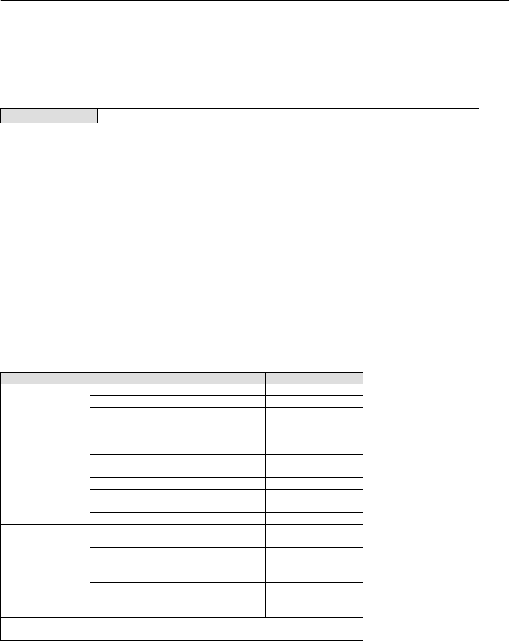
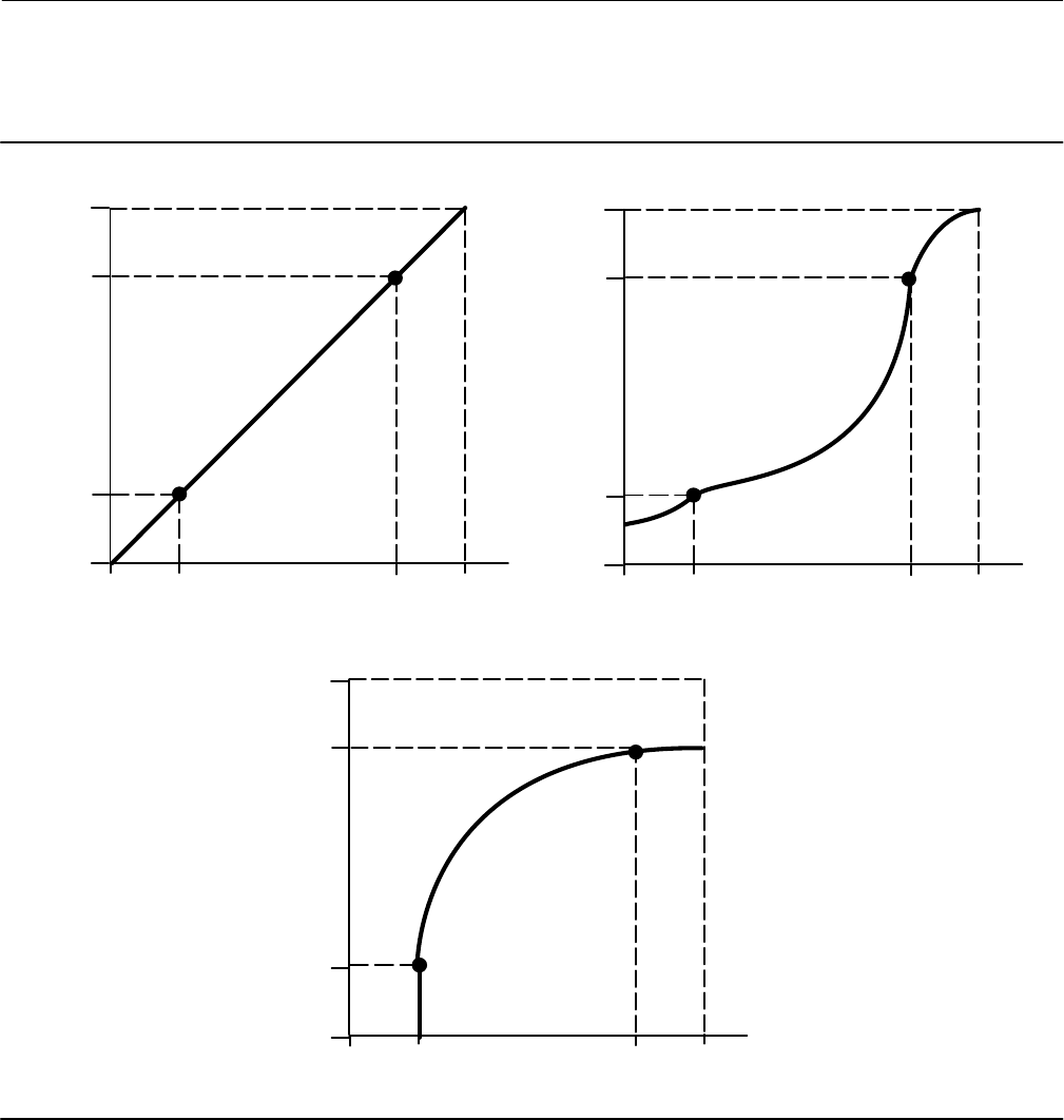
D Input Characterization
Input Characterization defines the relationship between the travel target and ranged set point. Ranged set point is the
input to the characterization function. If the zero power condition equals closed, then a set point of 0% corresponds to
a ranged input of 0%. If the zero power condition equals open, a set point of 0% corresponds to a ranged input of 100%.
Travel target is the output from the characterization function.
To select an input characterization, select Input Characterization from the Characterization menu. You can select from
the three fixed input characteristics shown in figure 3‐1 or you can select a custom characteristic. Figure 3‐1 shows the
relationship between the travel target and ranged set point for the fixed input characteristics, assuming the Zero
Power Condition is configured as closed.
You can specify 21 points on a custom characteristic curve. Each point defines a travel target, in % of ranged travel, for
a corresponding set point, in % of ranged set point. Set point values range from -6.25% to 106.25%. Before
modification, the custom characteristic is linear.
D Custom Characterization
To define a custom input character, from the Characterization menu select Custom Characterization. Select the point
you wish to define (1 to 21), then enter the desired set point value. Press Enter then enter the desired travel target for
the corresponding set point. When finished, select point 0 to return to the Characterization menu.
With input characterization you can modify the overall characteristic of the valve and instrument combination.
Selecting an equal percentage, quick opening, or custom (other than the default of linear) input characteristic
Instruction Manual
D103557X012
Configuration
January 2015
22
modifies the overall valve and instrument characteristic. However, if you select the linear input characteristic, the
overall valve and instrument characteristic is the characteristic of the valve, which is determined by the valve trim (i.e.,
the plug or cage).
Figure 3‐1. Travel Target Versus Ranged Set Point, for Various Input Characteristics (Zero Power Condition = Closed)
Travel Target, %
Ranged Set Point, %
-25 0 125100 -25 0 125100
-25 0 125100
Input Characteristic = Linear Input Characteristic = Equal Percentage
Input Characteristic = Quick Opening
100
0
-25
125
Travel Target, %
100
0
-25
125
Ranged Set Point, %
Travel Target, %
100
0
-25
125
Ranged Set Point, %
A6535‐1
Instruction Manual
D103557X012
Configuration
January 2015
23
Dynamic Response
D SP Rate Open—Maximum rate (% of valve travel per second) at which the digital valve controller will move to the
open position regardless of the rate of input current change. A value of 0 will deactivate this feature and allow the
valve to stroke open as fast as possible. In firmware 4 this parameter should be set to 0.
D SP Rate Close—Maximum rate (% of valve travel per second) at which the digital valve controller will move to the
close position regardless of the rate of input current change. A value of 0 will deactivate this feature and allow the
valve to stroke close as fast as possible. In firmware 4 this parameter should be set to 0.
D Set Point Filter Time (Lag Time)—The Set Point Filter Time (Lag Time) slows the response of the digital valve
controller. A value ranging from 0.2 to 10.0 can be used for noisy or fast processes to improve closed loop process
control. Entering a value of 0.0 will deactivate the lag filter. In firmware 4 this parameter should be set to 0.
Travel Cutoffs
D Hi Cutoff Point—This is the point within the calibrated travel range above which the cutoff is in effect. When using
cutoffs, a Cutoff Hi of 50% is recommended to ensure valve goes fully open.
D Lo Cutoff Point—This is the point within the calibrated travel range below which the cutoff is in effect. When using
cutoffs, a Cutoff Lo of 50% is recommended to help ensure maximum shutoff seat loading.
Tuning
Field Communicator Configure > Manual Setup > Tuning (2‐2-4)
Travel Tuning
WARNING
Changes to the tuning set may cause the valve/actuator assembly to stroke. To avoid personal injury and property damage
caused by moving parts, keep hands, tools, and other objects away from the valve/actuator assembly.
D Travel Tuning Set
There are eleven tuning sets to choose from. Each tuning set provides a preselected value for the digital valve
controller gain settings. Tuning set C provides the slowest response and M provides the fastest response.
Table 3‐4 lists the proportional gain, velocity gain and minor loop feedback gain values for preselected tuning sets.
Table 3‐4. Gain Values for Preselected Travel Tuning Sets
Tuning Set Proportional Gain Velocity Gain Minor Loop Feedback Gain
C
D
E
F
G
4.4
4.8
5.5
6.2
7.2
3.0
3.0
3.0
3.1
3.6
35
35
35
35
34
H
I
J
K
L
M
8.4
9.7
11.3
13.1
15.5
18.0
4.2
4.85
5.65
6.0
6.0
6.0
31
27
23
18
12
12
X (Expert) User Adjusted User Adjusted User Adjusted

Instruction Manual
D103557X012
Configuration
January 2015
24
In addition, you can specify Expert tuning and individually set the proportional gain, velocity gain, and minor loop
feedback gain. Individually setting or changing any tuning parameter or running the Performance Tuner or
Stabilize/Optimize routine will automatically change the tuning set to X (expert).
Note
Use Expert tuning only if standard tuning has not achieved the desired results.
Stabilize/Optimize or Performance Tuner may be used to achieve the desired results more rapidly than manual Expert tuning.
Table 3‐5 provides tuning set selection guidelines for Fisher and Baumann actuators. These tuning sets are only
recommended starting points. After you finish setting up and calibrating the instrument, you may have to select either
a higher or lower tuning set to get the desired response. You can use the Performance Tuner to optimize tuning.
D Proportional Gain—the proportional gain for the travel control tuning set. Changing this parameter will also change
the tuning set to Expert.
D Velocity Gain—the velocity gain for the travel control tuning set. Changing this parameter will also change the
tuning set to Expert.
D MLFB Gain—the minor loop feedback gain for the travel control tuning set. Changing this parameter will also change
the tuning set to Expert.
D Integral Enable—Yes or No. Enable the integral setting to improve static performance by correcting for error that
exists between the travel target and actual travel. Travel Integral Control is enabled by default.
D Integral Gain—Travel Integral Gain is the ratio of the change in output to the change in input, based on the control
action in which the output is proportional to the time integral of the input.
D Performance Tuner
WARNING
During performance tuning the valve may move, causing process fluid or pressure to be released. To avoid personal injury
and property damage caused by the release of process fluid or pressure, isolate the valve from the process and equalize
pressure on both sides of the valve or bleed off the process fluid.
The Performance Tuner is used to determine digital valve controller tuning. It can be used with digital valve controllers
mounted on most sliding‐stem and rotary actuators, including Fisher and other manufacturers' products. Moreover,
because the performance tuner can detect internal instabilities before they become apparent in the travel response, it
can generally optimize tuning more effectively than manual tuning. Typically, the performance tuner takes 3 to 5
minutes to tune an instrument, although tuning instruments mounted on larger actuators may take longer.

Instruction Manual
D103557X012
Configuration
January 2015
25
Table 3‐5. Actuator Information for Initial Setup
Actuator
Manufacturer Actuator Model Actuator Size Actuator Style Starting
Tuning Set
Travel Sensor Motion(2)
Relay A or C(3)
Fisher
585C & 585CR
25
50
60
68, 80
100, 130
Piston Dbl w/ or w/o
Spring. See actuator
instruction manual and
nameplate.
E
I
J
L
M
User Specified
657
30
34, 40
45, 50
46, 60, 70, 76, &
80‐100
Spring & Diaphragm
H
K
L
M
Away from the top of the instrument
667
30
34, 40
45, 50
46, 60, 70, 76, &
80‐100
Spring & Diaphragm
H
K
L
M
Towards the top of the instrument
1051 & 1052
20, 30
33
40
60, 70
Spring & Diaphragm
(Window‐mount)
H
I
K
M
Away from the top of the instrument
1061
30
40
60
68, 80, 100, 130
Piston Dbl w/o Spring
J
K
L
M
Depends upon pneumatic connections. See
description for Travel Sensor Motion
1066SR 20
27, 75 Piston Sgl w/Spring G
L
Mounting Style Travel Sensor Motion
AAway from the top of
the instrument
BTowards the top of the
instrument
CTowards the top of the
instrument
DAway from the top of
the instrument
2052
1
2
3
Spring & Diaphragm
(Window‐mount)
H
J
M
Away from the top of the instrument
3024C
30, 30E
34, 34E, 40, 40E
45, 45E
Spring & Diaphragm
E
H
K
For Po operating mode (air opens):
Towards the top of the instrument
For Ps operating mode (air closes):
Away from the top of the instrument
GX
225
Spring & Diaphragm
X(1) Air to Open
Towards the top of
the instrument
Air to Close
Away from the top of
the instrument
750 K
1200 M
Baumann
Air to Extend 16
32
54 Spring & Diaphragm
C
E
H
Towards the top of the instrument
Air to Retract Away from the top of the instrument
Rotary
10
25
54
E
H
J
Specify
NOTE: Refer to figure table 3‐6 for feedback connection (magnet assembly) information.
1. X = Expert Tuning. Proportional Gain = 4.2; Velocity Gain = 3.0; Minor Loop Feedback Gain = 18.0
2. Travel Sensor Motion in this instance refers to the motion of the magnet assembly.
3. Values shown are for Relay A and C. Reverse for Relay B.

Instruction Manual
D103557X012
Configuration
January 2015
26
D Stabilize/Optimize
WARNING
During Stabilize/Optimize the valve may move, causing process fluid or pressure to be released. To avoid personal injury
and property damage caused by the release of process fluid or pressure, isolate the valve from the process and equalize
pressure on both sides of the valve or bleed off the process fluid.
Stabilize/Optimize permits you to adjust valve response by changing the digital valve controller tuning. During this
routine, the instrument must be out of service; however, the instrument will respond to setpoint changes.
If the valve is unstable, select Decrease Response to stabilize valve operation. This selects the next lower tuning set
(e.g., F to E). If the valve response is sluggish, select Increase Response to make the valve more responsive. This selects
the next higher tuning set (e.g., F to G).
If after selecting Decrease Response or Increase Response the valve travel overshoot is excessive, select Decrease
Damping to select a damping value that allows more overshoot. Select Increase Damping to select a damping value that
will decrease the overshoot. When finished, select done.
Integral Settings
D Integral Dead Zone—A window around the Primary Setpoint in which integral action is disabled. This feature is used
to eliminate friction induced limit cycles around the Primary Setpoint when the integrator is active. The Dead Zone
is configurable from 0% to 2%, corresponding to a symmetric window from 0% to +/-2% around the Primary
Setpoint. Default value is 0.25%.
D Integrator Limit—The Integrator Limit provides an upper limit to the integrator output. The high limit is configurable
from 0 to 100% of the I/P drive signal.
Valve and Actuator
Field Communicator Configure > Manual Setup > Valve and Actuator (2‐2‐5)
Valve Style—Enter the valve style, rotary or sliding‐stem
Actuator Style—Enter the actuator style, spring and diaphragm, piston double‐acting without spring, piston
single‐acting with spring, or piston double‐acting with spring.
Feedback Connection—Refer to table 3‐6 for Feedback Connection options. Choose the assembly that matches the
actuator travel range.
Note
As a general rule, do not use less than 60% of the magnet assembly travel range for full travel measurement. Performance will
decrease as the assembly is increasingly subranged.
The linear magnet assemblies have a valid travel range indicated by arrows molded into the piece. This means that the hall sensor
(on the back of the DVC6200 SIS housing) has to remain within this range throughout the entire valve travel. The linear magnet
assemblies are symmetrical. Either end may be up.
Instruction Manual
D103557X012
Configuration
January 2015
27
Table 3‐6. Feedback Connection Options
Magnet Assembly Travel Range
mm Inch Degrees
SStem #7 4.2-7 0.17-0.28 -
SStem #19 8-19 0.32-0.75 -
SStem #25 20-25 0.76-1.00 -
SStem #38 26-38 1.01-1.50 -
SStem #50 39-50 1.51-2.00 -
SStem #110 51-110 2.01-4.125 -
SStem #210 110-210 4.125-8.25
SStem #1 Roller 210 8.25 60-90_
RShaft Window #1 - - 60-90_
RShaft Window #2 - - 60-90_
RShaft End Mount - - 60-90_
Relay Type—There are three categories of relays that result in combinations from which to select.
Relay Type: The relay type is printed on the label affixed to the relay body.
A = double‐acting or single‐acting
B = single‐acting, reverse
C= single‐acting, direct
Special App: This is used in single‐acting applications where the “unused” output port is configured to read the
pressure downstream of a solenoid valve.
Lo Bleed: The label affixed to the relay body indicates whether it is a low bleed version.
Zero Power Condition—The position of the valve (open or closed) when the electrical power to the instrument is
removed. Zero Power Condition (ZPC) is determined by relay type, as shown in figure 3‐2.
Figure 3‐2. Zero Power Condition
A
B
Single‐Acting Direct (Relay A or C)Port A pressure to zero.
Single‐Acting Reverse (Relay B)
Double‐Acting (Relay A)
Loss of Electrical Power
Port B pressure to full supply.
Port A pressure to zero.
Port B pressure to full supply.
Relay Type
X077-SIS
Travel Sensor Motion
WARNING
If you answer YES to the prompt for permission to move the valve when determining travel sensor motion, the instrument
will move the valve through a significant portion of its travel range. To avoid personal injury and property damage caused
by the release of process fluid or pressure, isolate the valve from the process and equalize pressure on both sides of the
valve or bleed off the process fluid.

Instruction Manual
D103557X012
Configuration
January 2015
28
Select Clockwise/Toward Bottom, or Counterclockwise/Toward Top. Travel Sensor Motion establishes the proper
travel sensor rotation. For quarter‐turn actuators determine rotation by viewing the rotation of the magnet assembly
from the back of the instrument.
Note
Travel Sensor Motion in this instance refers to the motion of the magnet assembly. Note that the magnet assembly may be
referred to as a magnetic array in user interface tools.
D For instruments with Relay A and C: If increasing air pressure at output A causes the magnet assembly to move
down or the rotary shaft to turn clockwise, enter CW/To Bottom Inst. If it causes the magnet assembly to move up,
or the rotary shaft to turn counterclockwise, enter CCW/To Top Inst.
D For instruments with Relay B: If decreasing air pressure at output B causes the magnet assembly to down, or the
rotary shaft to turn clockwise, enter CW/To Bottom Inst. If it causes the magnet assembly to move up, or the rotary
shaft to turn counterclockwise, enter CCW/To Top Inst.
Maximum Supply Pressure
Enter the maximum supply pressure that is required to fully stroke the valve.

Instruction Manual
D103557X012
Configuration
January 2015
29
SIS/Partial Stroke Test
Field Communicator Configure > Manual Setup > SIS/Partial Stroke (2-2-6)
Partial Stroke Test (PST)
D PST Pressure Limit— This defines the actuator pressure at which a partial stroke test will abort. This prevents the
DVC6200 SIS from exhausting (or building) excessive pressure to the actuator in an attempt to move a stuck valve.
During Device Setup or Auto Travel Calibration, the Partial Stroke Pressure Limit will be set automatically as follows:
Single Acting Actuators - For those actuators that exhaust pressure from the partial test start point, the Pressure
Limit will be a minimum value. For those actuators that build pressure from the partial test start point, the Pressure
Limit will be a maximum value.
Double Acting Actuators - The Pressure Limit will be set to a negative value for actuators where the partial stroke
start point is opposite of the Zero Power Condition (e.g., Partial Stroke Start Point = Open and Zero Power
Condition = Closed) and to a positive valve for actuators where the partial stroke start point is the same as the Zero
Power Condition.
The pressure signal used to determine this parameter depends on relay type and is summarized below.
Relay Type Pressure Signal
A or C Port A - Port B
B Port B - Port A
B Special App. Port B
C Special App. Port A
To manually set the partial stroke pressure limit, you must examine current partial stroke test results using ValveLink
software. The following steps will guide you through the process:
1. Connect the DVC6200 SIS to a system running ValveLink software.
2. Disable the following parameters:
D Travel Deviation Alert - set to 125%.
D End Point Pressure Control - disable
D Partial Stroke Pressure Limit - disable by setting the appropriate value shown in table 3‐7.
Table 3‐7. Values for Disabling Partial Stroke Pressure Limit
Actuator Type Relay Type Zero Power Condition Partial Stroke Start Point Partial Stroke Pressure Limit (Disabled)
Single Acting
A or C
Closed Open 0.0
Closed Psupply
Open Open Psupply
Closed 0.0
B
Closed Open Psupply
Closed 0.0
Open Open 0.0
Closed Psupply
Double Acting A
Closed Open -Psupply
Closed Psupply
Open Open Psupply
Closed -Psupply

Instruction Manual
D103557X012
Configuration
January 2015
30
3. Run a partial stroke test.
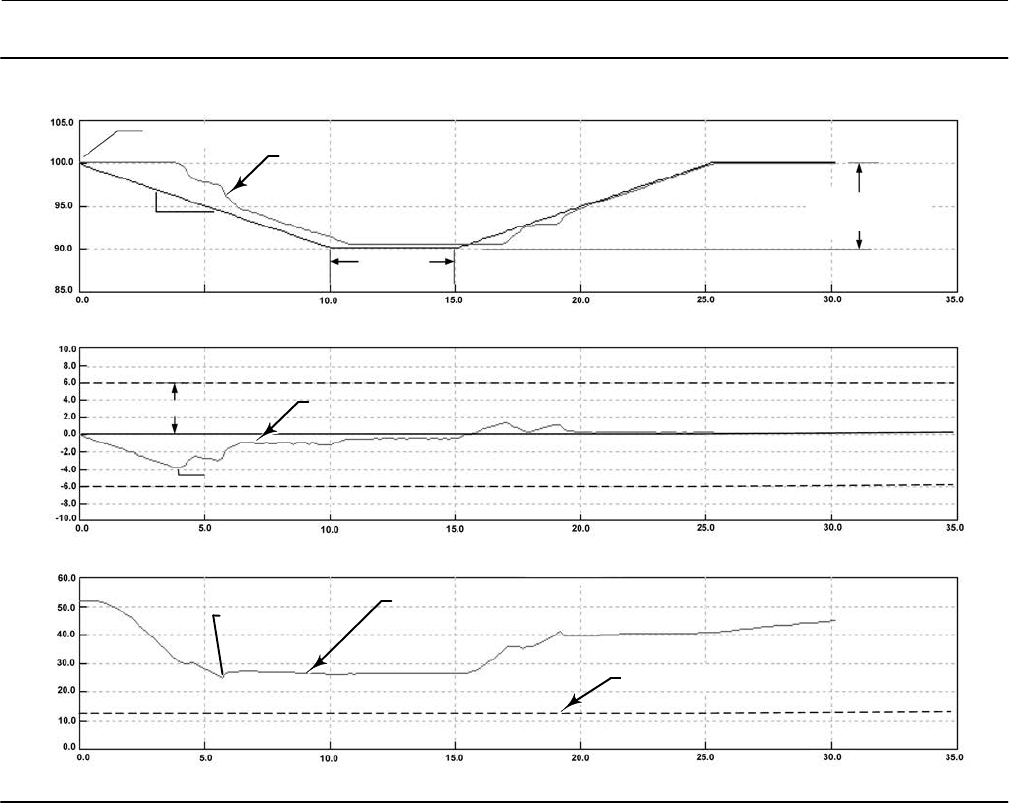
4. Select the Press/Time radio button on the partial stroke graph (refer to the example in figure 3‐3, bottom plot). If
the actuator pressure starts high and moves low, find the minimum actuator pressure (Pmin). If the actuator
pressure starts low and moves high, find the maximum actuator pressure (Pmax). Doubleacting actuators will
display differential pressure. Use table 3‐8 to estimate the partial stroke pressure limit.
Table 3‐8. Estimates for Partial Stroke Pressure Limits
Actuator Style Relay Type Zero Power Condition PST Starting Point Partial Stroke Pressure Limit(1)
Spring and
Diaphragm
A or C
Closed Open Pmin - 0.25 * (Bench Set High - Bench Set Low)
Closed Pmax + 0.25 * (Bench Set High - Bench Set Low)
Open Open Pmax + 0.25 * (Bench Set High - Bench Set Low)
Closed Pmin - 0.25 * (Bench Set High - Bench Set Low)
B
Closed Open Pmax + 0.25 * (Bench Set High - Bench Set Low)
Closed Pmin - 0.25 * (Bench Set High - Bench Set Low)
Open Open Pmin - 0.25 * (Bench Set High - Bench Set Low)
Closed Pmax + 0.25 * (Bench Set High - Bench Set Low)
Single Acting Piston
A or C
Closed Open 0.5 * Pmin
Closed Pmax + 0.5 * (Psupply - Pmax)
Open Open Pmax + 0.5 * (Psupply - Pmax)
Closed 0.5 * Pmin
B
Closed Open Pmax + 0.5 * (Psupply - Pmax)
Closed 0.5 * Pmin
Open Open 0.5 * Pmin
Closed Pmax + 0.5 * (Psupply - Pmax)
Double Acting Piston A
Closed Open Pmin - 0.5 * (Psupply + Pmin)
Closed Pmax + 0.5 * (Psupply - Pmax)
Open Open Pmax + 0.5 * (Psupply - Pmax)
Closed Pmin - 0.5 * (Psupply + Pmin)
5. Enable the parameters that were previously disabled:
D Travel Deviation Alert - set to 1.5x the maximum travel deviation between travel set point and travel.
D End Point Pressure Control - enable
D Partial Stroke Pressure Limit - calculate the value using table 3‐8.
PST Enable—Yes or No. This enables or disables the Partial Stroke Test.
PST Start Point—Valve Open or Valve Closed. This defines the travel stop that the valve needs to be at before a partial
stroke test can be initiated. This also defines the travel stop for end point pressure control. Setting this value to Not
Configured will disable partial stroke tests and end point pressure control.
PST Variables—Follow the prompts on the Field Communicator display to enter or view information for following PST
Variables:
D Max Travel Movement— This is the percentage of total span that the valve moves away from its normal operating
state towards its tripped state during the test. The default value is 10%.
D Test Speed—This is the rate at which the valve will move during the test. The default value is 0.25%/second.
D Pause Time—This is the pause time between the up and down strokes of the test. The default value is 5 seconds.
Instruction Manual
D103557X012
Configuration
January 2015
31
Figure 3‐3. Example Time Series Plots of Travel Set Point, Travel, Error, and Actuator Pressure
ACTUAL TRACE FROM TEST (TYPICAL)
ACTUAL TRACE FROM TEST (TYPICAL)
ACTUAL TRACE FROM TEST (TYPICAL)
TEST START POINT
TEST SPEED
(% / SEC)
TEST PAUSE
TIME (SEC)
MAX. TRAVEL
MOVEMENT (5%)
TVL SET POINT, TRAVEL (%)ERROR (%)
PRESSURE (%)
TIME (SEC)
TIME (SEC)
TIME (SEC)
PARTIAL STROKE PRESSURE LIMIT
TRAVEL DEVIATION ALERT PT.
MAXIMUM DEVIATION
MINIMUM PRESSURE
(Pmin)

Instruction Manual
D103557X012
Configuration
January 2015
32
SIS Options
D Auto Test Interval—This is the interval of time (in days) between partial stroke tests that are automatically run by the
digital valve controller, subject to the device being powered up. A value of 0 disables this feature.
D LoopInitiated PST—When this feature is enabled, the digital valve controller will run a partial stroke test if the loop
current is set to within +/0.5% of the PST trip point. The loop current must remain at that point for the duration of
the test. To abort the test, the loop current must be returned to the normal or tripped current. This feature is
disabled by default. This feature is not available when a looppowered local control panel is installed.
PST Trip Point (ETT) - This is the point at which the loop current must be set to run a partial stroke test for
energizetotrip applications. This value is not configurable.
PST Trip Point (DETT) - This is the point at which the loop current must be set to run a partial stroke test for
deenergizetotrip applications. This value is not configurable.
D Device Power Up Reset—This defines the power up behavior of the DVC6200 SIS. Auto Reset allows the valve to
track the command signal when power is applied to the device. Manual Reset will lock the device in its safety
position until the digital valve controller is reset.
If Manual Reset is selected, its state can be determined from the status monitor by monitoring the Locked In Safety
Position alert.
When Auxiliary Terminal Action is set to SIS Local Control Panel, Device Power Up is set to Manual Reset and cannot
be changed to Auto Reset.
The reset signal depends on how the AUX terminals are configured. If configured for SIS Local Control Panel, the
digital valve controller can be reset by pressing the button next to the green light on the LCP100. If configured as
Push Button Partial Stroke, the digital valve controller can be reset by shorting the AUX terminals for more than 3
seconds but less than 10 seconds. The device cannot be reset from the AUX terminals if they are configured
otherwise.
D Action on Failed Test—This displays the action taken by the instrument if a communication timeout occurs. Values
are Ramp Back or Step Back.
Outputs
Field Communicator Configure > Manual Setup > Outputs (2-2-6)
Output Terminal Configuration
D Output Terminal Enable—If using the output terminal for a Position Transmitter or Switch output, this must be
Enabled.
D Function—The output terminals can be configured as one of the following:
Transmitter - 420 mA output that represents 0100% of the calibrated valve travel.
Limit Switch - Discrete switch (1A max) that trips at a configurable point within 0100% of calibrated valve travel.
Alert Switch - Discrete switch (1A max) that trips based on a configurable device alert.
D Fail Signal—Should the output circuit fail to operate properly; the output will attempt to drive to a known state.
Depending on the nature of the failure, the circuit may or may not be able to achieve this fail state. When

Instruction Manual
D103557X012
Configuration
January 2015
33
configured as a transmitter, the output can be configured to drive high (22.5 mA) or low (3.6 mA). When
configured as a switch, the output can be configured to drive Closed or Open.
Note
On loss of positioner power, the switch circuit will always go to the open state. However, on loss of positioner power, the
transmitter output will continue to operate as long as the transmitter circuit is still powered and functioning.
Switch Configuration
D Limit Switch Trip Point—When the function is configured as a Limit Switch, this defines the threshold for the limit
switch in percent of calibrated travel.
D Alert Switch Source—When the function is configured as a Alert Switch, this determines which alert will activate the
switch. The alert choices are: Travel Deviation, Valve Stuck, LCP Tripped, SIS Diagnostic Credit, or Diagnostic in
Progress.
D Switch Closed—This configures the action of the switch. The choices are: Below Trip Point / Alert Not Active or
Above Trip Point / Alert Active.
HART Variable Assignments
Instrument variables can be reported via four different HART variable assignments. The Primary Variable is always
configured as Analog Input. However, the remaining three variables have additional options as listed below.
Primary Variable (PV) Analog Input
Secondary Variable (SV) Travel, Travel Setpoint, Pressure A, Pressure B, Pressure AB, Supply Pressure,
Drive Signal, or Analog Input
Tertiary Variable (TV) Travel, Travel Setpoint, Pressure A, Pressure B, Pressure AB, Supply Pressure,
Drive Signal, or Analog Input
Quaternary Variable (QV) Travel, Travel Setpoint, Pressure A, Pressure B, Pressure AB, Supply Pressure,
Drive Signal, or Analog Input
Transmitter Output
This configures the relationship between the valve travel and the position transmitter output signal. There are two
choices; 4mA = Valve Closed or 4mA = Valve Open.
Burst Mode
Burst mode provides continuous communication from the digital valve controller. Burst mode applies only to the
transmission of burst mode data (HART Variable Assignments) and does not affect the way other data is accessed.
Burst mode is only available in devices configured as HART Universal Revision 5.
D Burst Enable—This turns on or off the burst mode.

Instruction Manual
D103557X012
Configuration
January 2015
34
D Burst Command—This defines which HART command is configured for burst reporting. There are three options to
choose from. When using a TriLoop, select the third option.
- Analog Input (Command 1)
- Loop Current / Travel (Command 2)
- Loop Current / PV / SV / TV / QV (Command 3)
Note
Access to information in the instrument is normally obtained through the poll/response of HART communication. The Field
Communicator or the control system may request any of the information that is normally available, even while the instrument is in
burst mode. Between each burst mode transmission sent by the instrument, a short pause allows the Field Communicator or
control system to initiate a request. The instrument receives the request, processes the response message, and then continues
“bursting” the burst mode data.
Burst mode will be automatically disabled during diagnostics tests such as Valve Signature.
Alert Setup
Field Communicator Configure > Alert Setup (2‐3)
An alert is a notification that the instrument has detected a problem. A shutdown is an action that the instrument
takes to drive the air output to the Zero Power Condition as per figure 3‐2. Some alerts can be configured to shutdown
the instrument. Refer to table 3‐9 for default alert and shutdown settings.
Alerts may be enabled or disabled with the instrument In Service, Out of Service, Protected, or Not Protected.
However, the instrument must be Not Protected to enable or disable a shutdown. Alerts are not processed when a
diagnostic is in progress.
If shutdown is enabled, and the alert is active, the instrument will latch in the shutdown state until power to the
instrument is cycled and the alert has cleared. While in the shutdown condition, HART communication will continue if
the instrument remains powered.

Instruction Manual
D103557X012
Configuration
January 2015
35
Table 3‐9. Default Alert and Shutdown Settings
Alert Default Alert Setting Default Shutdown Setting
Travel Sensor Failure Enabled Disabled
Temperature Sensor Failure Enabled Disabled
Minor Loop Sensor Failure Enabled Disabled
Pressure Sensor Failure Enabled Disabled
Drive Current Failure Enabled Disabled
Critical NVM Failure Enabled Disabled
Non-Critical NVM Failure Enabled Disabled
Flash Integrity Failure Enabled Disabled
Reference Voltage Failure Enabled Disabled
SIS Program Flow Failure Enabled Disabled
SIS Hardware Failure Enabled Disabled
Loop Current Validation Enabled Disabled
Drive Signal Out of Range Enabled Not Available
Supply Pressure Low Enabled Not Available
Travel Deviation Enabled Not Available
High Travel Disabled Not Available
Low Travel Disabled Not Available
High-High Travel Disabled Not Available
Low-Low Travel Disabled Not Available
Travel Cutoff High Disabled Not Available
Travel Cutoff Low Disabled Not Available
Integrator Saturated High Disabled Not Available
Integrator Saturated Low Disabled Not Available
Cycle Count High Disabled Not Available
Travel Accumulator High Disabled Not Available
Valve Stuck Disabled Not Available
End Point Pressure Control Deviation Disabled Not Available
Tripped by the LCP Disabled Not Available
SIS Locked in Safety Position Disabled Not Available
LCP Communication Failure Disabled Not Available
Output Circuit Communication Failure Disabled Not Available
Alert Record Not Empty Disabled Not Available
Alert Record Full Disabled Not Available
Instrument Time is Approximate Disabled Not Available
For a detailed explanation of the alerts and the recommended actions, refer to Section 5.

Instruction Manual
D103557X012
Configuration
January 2015
36
Change to HART 5 / Change to HART 7
Field Communicator Service Tool > Maintenance > Change to HART 5 / Change to HART 7 (3-5-3)
This procedure changes the instrument from HART Universal Revision 5 to HART Universal Revision 7 (or vice versa).
Before proceeding, verify that your systems are prepared to support HART Universal Revision 7 devices. Follow the
prompts on the Field Communicator display.
Note
This procedure must never be done while the valve is in service and controlling the process. Depending on the control system or
asset management system attached, complete system reset may be required to reestablish HART communication. Consult the
system documentation for further information.

Instruction Manual
D103557X012
Calibration
January 2015
37
Section 4 Calibration 44
Calibration Overview
When a DVC6200 SIS digital valve controller is ordered as part of a control valve assembly, the factory mounts the
digital valve controller on the actuator and connects the necessary tubing, then sets up and calibrates the controller.
For digital valve controllers that are ordered separately, recalibration of the analog input or pressure sensors generally
is unnecessary. However, after mounting on an actuator, perform the initial setup then calibrate travel by selecting
Configure > Calibration > Travel Calibration > Auto Calibration. For more detailed calibration information, refer to the
following calibration procedures.
Field Communicator Configure > Calibration (2-4)
Auto Travel Calibration - see page 38
Manual Travel Calibration - see page 39
Pushbutton Calibration - see page 40
Pressure Sensor Calibration - see page 41
Analog Input Calibration - see page 42
Relay Adjustment - see page 43
PST Calibration - see page 45
Note
The Instrument Mode must be Out Of Service and the Protection set to None before the instrument can be calibrated.
If you are operating in burst mode, we recommend that you disable burst before continuing with calibration. Once calibration is
complete, burst mode may then be turned back on.
WARNING
During calibration the valve will move full stroke. To avoid personal injury and property damage caused by the release of
pressure or process fluid, isolate the valve from the process and equalize pressure on both sides of the valve or bleed off the
process fluid.

Instruction Manual
D103557X012
Calibration
January 2015
38
Travel Calibration
If a double‐acting relay is used, you will be prompted to run the relay adjustment when auto or manual calibration is
selected. Select Yes to adjust the relay, select No to proceed with calibration. For additional information, refer to Relay
Adjustment on page 43.
Auto Calibration
1. The auto calibration procedure is automatic. It is completed when the Calibration menu appears.
During calibration, the instrument seeks the high and low end points and the minor loop feedback (MLFB) and output
bias. By searching for the end points, the instrument establishes the limits of physical travel, i.e. the actual travel 0 and
100% positions. This also determines how far the relay beam swings to calibrate the sensitivity of the MLFB sensor.
2. Place the instrument In Service and verify that the travel properly tracks the current source.
If the unit does not calibrate, refer to table 4‐1 for error messages and possible remedies.
Table 4‐1. Auto Calibrate Travel Error Messages
Error Message Possible Problem and Remedy
Power failure occurred during Auto Calib The analog input signal to the instrument must be greater than 3.8 mA. Adjust the current output
from the control system or the current source to provide at least 4.0 mA.
Auto Calib did not complete within the time limit.
The problem may be one or the other of the following:
1. The tuning set selected is too low and the valve does not reach an end point in the allotted time.
Select Manual Setup > Tuning > Travel Tuning > Stabilize/Optimize then Increase Response (selects next
higher tuning set).
2. The tuning set selected is too high, valve operation is unstable and does not stay at an end point
for the allotted time. Select Manual Setup > Tuning > Travel Tuning > Stabilize/Optimize then Decrease
Response (selects next lower tuning set).
Insufficient travel
Prior to receiving this message, did the instrument output go from zero to full supply? If not, verify
instrument supply pressure by referring to the specifications in the appropriate actuator instruction
manual. If supply pressure is correct, check instrument pneumatic components (I/P converter and
relay).
If the instrument output did go from zero to full supply prior to receiving this message, then verify
proper mounting by referring to the appropriate mounting procedure in the Installation section and
checking the magnet array for proper alignment.
Drive signal exceed low limit; check supply
pressure
1. Check supply pressure (reverse‐acting relay)
2. Friction is too high.
Drive signal exceed high limit; check supply
pressure
1. Check supply pressure (direct‐acting relay)
2. Friction is too high

Instruction Manual
D103557X012
Calibration
January 2015
39
Manual Calibration
Two procedures are available to manually calibrate travel:
D Analog Adjust— This procedure is used when you can manually change the 4-20 mA current source to move the
valve.
D Digital Adjust— This procedure is used when the 4-20 mA current source cannot be manually changed.
Analog Calibration Adjust
Connect a variable current source to the instrument LOOP + and LOOP - terminals. The current source should be
capable of generating 4 to 20 mA.
Follow the prompts on the Field Communicator display to calibrate the instrument's travel in percent.
Note
0% Travel = Valve Closed
100% Travel = Valve Open
1. Adjust the input current until the valve is near mid‐travel. Press OK.
Note
In steps 2 through 7 the accuracy of the current source adjustment affects the position accuracy.
2. Adjust the current source until the valve is at 0% travel, then press OK.
3. Adjust the current source until the valve is at 100% travel, then press OK.
4. Adjust the current source until the valve is at 0% travel, then press OK.
5. Adjust the current source until the valve is at 100% travel, then press OK.
6. Adjust the current source until the valve is at 5% travel, then press OK.
7. Adjust the current source until the valve is at 95% travel, then press OK.
8. Place the instrument In Service and verify that the travel properly tracks the current source.
Digital Calibration Adjust
Connect a variable current source to the instrument LOOP + and LOOP - terminals. The current source should be set
between 4 and 20 mA.
Follow the prompts on the Field Communicator display to calibrate the instrument's travel in percent.
1. Adjust the input current until the valve is near mid‐travel. Press OK.
Note
0% Travel = Valve Closed
100% Travel = Valve Open

Instruction Manual
D103557X012
Calibration
January 2015
40
2. From the adjustment menu, select the direction and size of change required to set the travel at 0%.
Selecting large, medium, and small adjustments causes changes of approximately 10.0%, 1.0%, and 0.1%, respectively.
If another adjustment is required, repeat step 2. Otherwise, select Done and go to step 3.
3. From the adjustment menu, select the direction and size of change required to set the travel to 100%.
If another adjustment is required, repeat step 3. Otherwise, select Done and go to step 4.
4. From the adjustment menu, select the direction and size of change required to set the travel at 0%.
If another adjustment is required, repeat step 4. Otherwise, select Done and go to step 5.
5. From the adjustment menu, select the direction and size of change required to set the travel to 100%.
If another adjustment is required, repeat step 5. Otherwise, select Done and go to step 6.
6. From the adjustment menu, select the direction and size of change required to set the travel to 5%.
If another adjustment is required, repeat step 6. Otherwise, select Done and go to step 7.
7. From the adjustment menu, select the direction and size of change required to set the travel to 95%.
If another adjustment is required, repeat step 7. Otherwise, select Done and go to step 8.
8. Place the instrument In Service and verify that the travel properly tracks the current source.
Pushbutton Calibration
A pushbutton near the wiring terminals in the terminal box provides a quick means to autocalibrate the instrument.
The button must be pressed for 3 to 10 seconds. Autocalibration will move the valve through the full range of travel
whether the Instrument Mode is In Service or Out of Service. However, if the Write Protection is Protected, this button
will not be active. To abort, press the button again for 1 second. The calibration button is disabled by default. To
enable it, go to Manual Setup > Instrument > Calibration Button.
Note
The autocal pushbutton will not be active if the instrument is Locked in Safety.
This calibration procedure is recommended whenever the I/P converter or pneumatic relay is replaced. Do not use the
pushbutton calibration for initial calibration when mounting the instrument on an actuator, or if the printed wiring
board assembly was replaced.
If you suspect calibration has changed due to drift, first perform a Valve Signature diagnostic test using ValveLink
software to capture the asfound data for future root cause analysis.
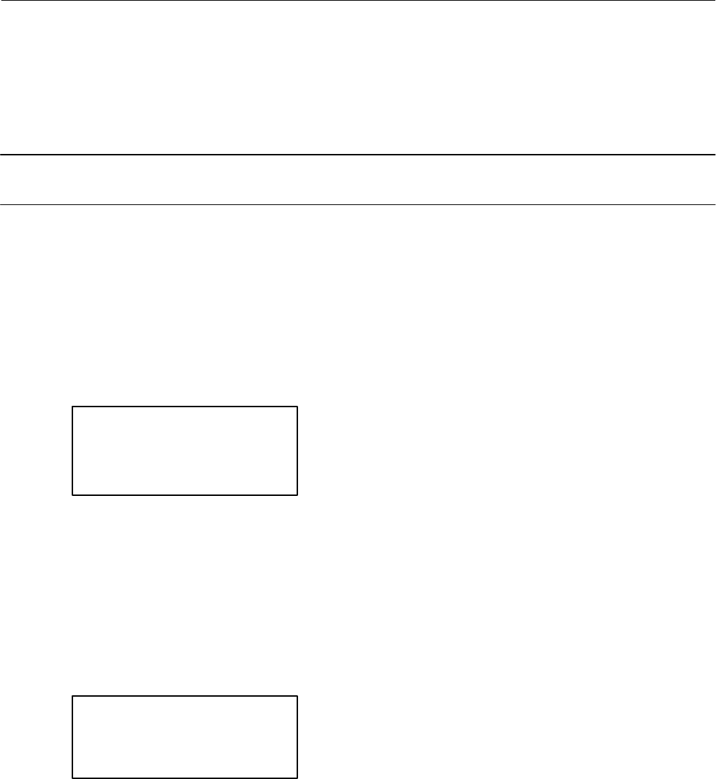
Instruction Manual
D103557X012
Calibration
January 2015
41
Sensor Calibration
Pressure Sensors
Note
The pressure sensor is calibrated at the factory and should not require calibration.
Output Pressure Sensor
To calibrate the output pressure sensor, connect an external reference gauge to the output being calibrated. The
gauge should be capable of measuring maximum instrument supply pressure. Depending upon the sensor you wish to
calibrate, select either Output A Sensor or Output B Sensor. Follow the prompts on the Field Communicator display to
calibrate the instrument's output pressure sensor.
1. Adjust the supply pressure regulator to the maximum instrument supply pressure. Press OK.
2. The instrument reduces the output pressure to 0. The following message appears.
Use the Increase and Decrease
selections until the displayed
pressure matches the output x
pressure.
Press OK when you have read the message.
3. The value of the output pressure appears on the display. Press OK to display the adjustment menu.
4. From the adjustment menu, select the direction and size of adjustment to the displayed value.
Selecting large, medium, and small adjustments causes changes of approximately 3.0 psi/0.207 bar/20.7 kPa, 0.30
psi/0.0207 bar/2.07 kPa, and 0.03 psi/0.00207 bar/0.207 kPa, respectively.
If the displayed value does not match the output pressure, press OK, then repeat this step (step 4) to further adjust the
displayed value. When the displayed value matches the output pressure, select Done and go to step 5.
5. The instrument sets the output pressure to full supply. The following message appears.
Use the Increase and Decrease
selections until the displayed
pressure matches the output x
pressure.
Press OK when you have read the message.
6. The value of the output pressure appears on the display. Press OK to display the adjustment menu.
7. From the adjustment menu, select the direction and size of adjustment to the displayed value. If the displayed value
does not match the output pressure, press OK, then repeat this step (step 7) to further adjust the displayed value.
When the displayed value matches the output pressure, select Done and go to step 8.
8. Place the instrument In Service and verify that the displayed pressure matches the measured output pressure.

Instruction Manual
D103557X012
Calibration
January 2015
42
Supply Pressure Sensor
To calibrate the supply pressure sensor, connect an external reference gauge to the output side of the supply
regulator. The gauge should be capable of measuring maximum instrument supply pressure. Follow the prompts on
the Field Communicator display to calibrate the instrument's supply pressure sensor.
1. Select a) Zero Only, or b) Zero and Span (gauge required).
a. If Zero Only calibration is selected, adjust the supply pressure regulator to remove supply pressure from the
instrument. Press OK. Once calibration is complete, go to step 5.
b. If Zero and Span calibration is selected, adjust the supply pressure regulator to remove supply pressure from the
instrument. Press OK. Adjust the supply regulator to the maximum instrument supply pressure. Press OK.
Proceed with step 2.
2. The following message appears:
Use the Increase and Decrease
selections until the displayed
pressure matches the supply
pressure.
Press OK when you have read this message.
3. The value of the pressure appears on the display.
4. From the adjustment menu, select the direction and size of adjustment to the displayed value.
Selecting large, medium, and small adjustments causes changes of approximately 3.0 psi/0.207 bar/20.7 kPa, 0.30
psi/0.0207 bar/2.07 kPa, and 0.03 psi/0.00207 bar/0.207 kPa, respectively.
Adjust the displayed value until it matches the supply pressure, select Done and go to step 5.
5. Place the instrument In Service and verify that the displayed pressure matches the measured supply pressure.
Analog Input Calibration
To calibrate the analog input sensor, connect a variable current source to the instrument LOOP+ and LOOP- terminals.
The current source should be capable of generating an output of 4 to 20 mA. Follow the prompts on the Field
Communicator display to calibrate the analog input sensor.
1. Set the current source to the target value shown on the display. The target value is the Input Range Low value. Press
OK.
2. The following message appears:
Use the Increase and Decrease
selections until the displayed
current matches the target.
Press OK when you have read this message.
3. The value of the Analog Input appears on the display. Press OK to display the adjustment menu.
4. From the adjustment menu, select the direction and size of adjustment to the displayed value.
Selecting large, medium, and small adjustments causes changes of approximately 0.4 mA, 0.04 mA, and 0.004 mA,
respectively.

Instruction Manual
D103557X012
Calibration
January 2015
43
If the displayed value does not match the current source, press OK, then repeat this step (step 4) to further adjust the
displayed value. When the displayed value matches the current source, select Done and go to step 5.
5. Set the current source to the target value shown on the display. The target value is the Input Range High value.
Press OK.
6. The following message appears:
Use the Increase and Decrease
selections until the displayed
current matches the target.
Press OK when you have read this message.
7. The value of the Analog Input appears on the display. Press OK to display the adjustment menu.
8. From the adjustment menu, select the direction and size of adjustment to the displayed value. If the displayed value
does not match the current source, press OK, then repeat this step (step 8) to further adjust the displayed value.
When the displayed value matches the current source, select Done and go to step 9.
9. Place the instrument In Service and verify that the analog input displayed matches the current source.
Relay Adjustment
Before beginning travel calibration, check the relay adjustment. Replace the digital valve controller cover when
finished.
Note
Relay B and C are not user‐adjustable.
Double‐Acting Relay
The double‐acting relay is designated by “Relay A” on a label affixed to the relay itself. For double‐acting actuators, the
valve must be near mid‐travel to properly adjust the relay. The Field Communicator will automatically position the
valve when Relay Adjust is selected.
Rotate the adjustment disc, shown in figure 4‐1, until the output pressure displayed on the Field Communicator is
between 50 and 70% of supply pressure. This adjustment is very sensitive. Be sure to allow the pressure reading to
stabilize before making another adjustment (stabilization may take up to 30 seconds or more for large actuators).
Low bleed relay stabilization may take approximately two minutes longer than the standard relay.
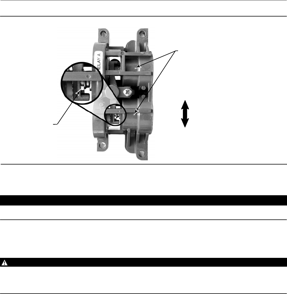
Instruction Manual
D103557X012
Calibration
January 2015
44
Figure 4‐1. Relay A Adjustment (Shroud Removed for Clarity)
ADJUSTMENT DISC
FOR DOUBLE‐ACTING RELAYS:
ROTATE ADJUSTMENT DISC IN
THIS DIRECTION TO INCREASE
OUTPUT PRESSURE
FOR DOUBLE‐ACTING RELAYS:
ROTATE ADJUSTMENT DISC IN
THIS DIRECTION TO DECREASE
OUTPUT PRESSURE
FOR SINGLE‐ACTING DIRECT RELAYS:
ROTATE ADJUSTMENT DISC IN THIS
DIRECTION UNTIL IT CONTACTS THE
BEAM
LOW BLEED RELAY DOES
NOT HAVE BLEED HOLES
W9305
Relay A may also be adjusted for use in single‐acting‐ direct applications. Rotate the adjustment disc as shown in figure
4‐1 for single‐acting direct operation.
CAUTION
Care should be taken during relay adjustment as the adjustment disc may disengage if rotated too far.
Single‐Acting Relays
WARNING
If the unused port is monitoring pressure, ensure that the pressure source conforms to ISA Standard 7.0.01 and does not
exceed the pressure supplied to the instrument.
Failure to do so could result in personal injury or property damage caused by loss of process control.
Single‐Acting Direct Relay
The single‐acting direct relay is designated by “Relay C” on a label affixed to the relay itself. Relay C requires no
adjustment.
Single‐Acting Reverse Relay
The single‐acting reverse relay is designated by “Relay B” on a label affixed to the relay itself. Relay B is calibrated at the
factory and requires no further adjustment.

Instruction Manual
D103557X012
Calibration
January 2015
45
PST Calibration
This procedure permits you to run the Partial Stroke Calibration, which enables the Partial Stroke Test. It establishes
values for Partial Stroke Pressure Limit, Pressure Set Point and Pressure Saturation Time for End Point Pressure Control,
Travel Deviation Alert Point and Travel Deviation Time. The Partial Stroke Calibration also sets default values for max
travel movement, test speed, and test pause time.
Note
You must take the instrument out of service before running Partial Stroke Calibration.
Ensure that the instrument is put back in service after the completing the calibration procedure.

Instruction Manual
D103557X012
Calibration
January 2015
46

Instruction Manual
D103557X012
Device Information, Diagnostics, and Alerts
January 2015
47
Section 5 Device Information, Diagnostics, and Alerts55
Overview
Field Communicator Overview (1)
Status & Primary Purpose Variables
The overview section provides basic information about the current state of the instrument and gives you access to the
current values of:
D Alert Status
D Communication Status
D Instrument Mode (In/Out of Service)
D Analog Input
D Setpoint
D Travel
D Supply Pressure
D Actuator Pressure(s)
Device Information
Device Information provides details about the instrument construction including:
D Tag Name
D Instrument Model Number
D Instrument Level
D Device ID (unique number used to prevent the instrument from accepting commands intended for other
instruments)
D Serial Numbers
D Firmware, DD, and Hardware Revisions
D HART Universal Revision
D Write Protection (provides a procedure to enable/disable)

Instruction Manual
D103557X012
Device Information, Diagnostics, and Alerts
January 2015
48
Service Tools
Field Communicator Service Tools (3)
Device Status
Instrument alerts, when enabled, detect many operational and performance issues that may be of interest. If there are
no alerts currently active, this display will be empty.
Alert Record
The DVC6200 SIS will store 20 alerts. Once the alert record is full, no additional alerts will be stored until the record is
cleared.
Below is a list of the alerts that can be detected by the instrument. To enable or disable the alerts, navigate to
Configure > Alert Setup.
D Offline/Failed Alert—This alert is active if a shutdown alert has put the device in a failed state and is therefore not
controlling the input. Press Enter to view the alert(s) that caused the shutdown.
Electronics
D Drive Current Failure—This alert is active when the drive current to the I/P converter is not flowing as expected. If
this alert occurs, check the connection between the I/P converter and the printed wiring board assembly. Try
removing the I/P converter and reinstalling it. If the alert does not clear, replace the I/P converter or the printed
wiring board assembly.
D Drive Signal Alert—This alert monitors the drive signal and calibrated travel. If one of the following conditions exists
for more than 20 seconds, the alert is set.
For the case where Zero Power Condition is defined as closed:
Drive Signal < 10% and Calibrated Travel > 3%
Drive Signal > 90% and Calibrated Travel < 97%
For the case where Zero Power Condition is defined as open:
Drive Signal < 10% and Calibrated Travel < 97%
Drive Signal > 90% and Calibrated Travel > 3%
D NonCritical NVM Alert—This alert is active if there is a failure associated with NVM (nonvolatile memory) that is not
critical for instrument operation. If this alert is active, restart the instrument. If the alert persists, replace the printed
wiring board assembly.
D Critical NVM Failure—This alert is active if there is a failure associated with NVM that is critical for instrument
operation. If this alert is active, restart the instrument. If the alert persists, replace the printed wiring board
assembly.
D Flash Integrity Failure—This alert is active if there is a failure associated with flash ROM (read only memory). If this
alert is active, restart the instrument. If the alert persists, replace the printed wiring board assembly.
D Reference Voltage Failure—This alert is active if there is a failure associated with the internal voltage reference. If
this alert is active, replace the printed wiring board assembly.

Instruction Manual
D103557X012
Device Information, Diagnostics, and Alerts
January 2015
49
D Variable Out of Range—This alert is active if one or more of the measured analog sensor readings (loop current,
pressure, temperature, or travel) is saturated or reading out of its configured range. The condition may be due to
improper configuration or physical setup and not be due to a sensor malfunction.
D Field Device Malfunction—This alert is active if the pressure, position, or temperature sensors are providing invalid
readings.
D Internal Sensor Out of Limits—This alert is active if there is a problem with either the pressure sensor or the printed
wiring board assembly.
D Travel Sensor Failure—This alert is active if the sensed travel is outside the range of 25.0 to 125.0% of calibrated
travel. If this alert is active, check the instrument mounting. Also, check that the electrical connection from the
travel sensor is properly plugged into the printed wiring board assembly. After restarting the instrument, if the alert
persists, troubleshoot the printed wiring board assembly or travel sensor.
D Temperature Sensor Failure—This alert is active when the instrument temperature sensor fails, or the sensor reading
is outside of the range of 60 to 100°C (76 to 212°F). The temperature reading is used internally for temperature
compensation of inputs. If this alert is active, restart the instrument. If the alert persists, replace the printed wiring
board assembly.
D Pressure Sensor Failure—This alert is active if any of the 3 pressure sensor readings are outside the range of 24.0 to
125.0% of the calibrated pressure for more than 60 seconds. If this alert is active, check the instrument supply
pressure, ensure the printed wiring board assembly is properly mounted onto the module base assembly, and
ensure the pressure sensor orings are properly installed. If the alert persists after restarting the instrument, replace
the printed wiring board assembly.
D Minor Loop Sensor Alert—This alert is active if the pneumatic relay position reading is outside the valid range. If the
alert persists, replace the printed wiring board.
D Loop Current Validation Alert—This alert is active if the loop current is significantly out of range, or if there is a
problem with the analog circuit electronics. If this alert is active, restart the instrument with the loop current
verified to be in the 420 mA range. If the alert persists, replace the printed wiring board.
Note
If the control system is known to output current 24 mA or above, Shutdown on Loop Current Validation should not be enabled.
D Output Circuit Communication Failure—This alert is active if the output circuit is not responding. If configured as a
position transmitter output, first make sure the transmitter circuit is powered. If the alert persists, make sure the
DIP switch on the main electronics matches the configuration of the OUT terminals. If the alert is still active, replace
the main electronics.
D Instrument Time is Approximate Alert—This alert is active if the instrument has been powered down since the last
time the instrument clock was set. To clear the alert, reset the instrument time.
D SIS Program Flow Failure—This alert is active if the firmware is not performing the expected series of calculations.
D SIS Hardware Failure—This alert is active if a demand has occurred, but the electronics hardware failed to take
control of the I/P drive.
D LCP Communication Failure—This alert is active if the AUX terminals are configured for use with the local control
panel, but communication between the DVC6200 SIS and LCP is not occurring.
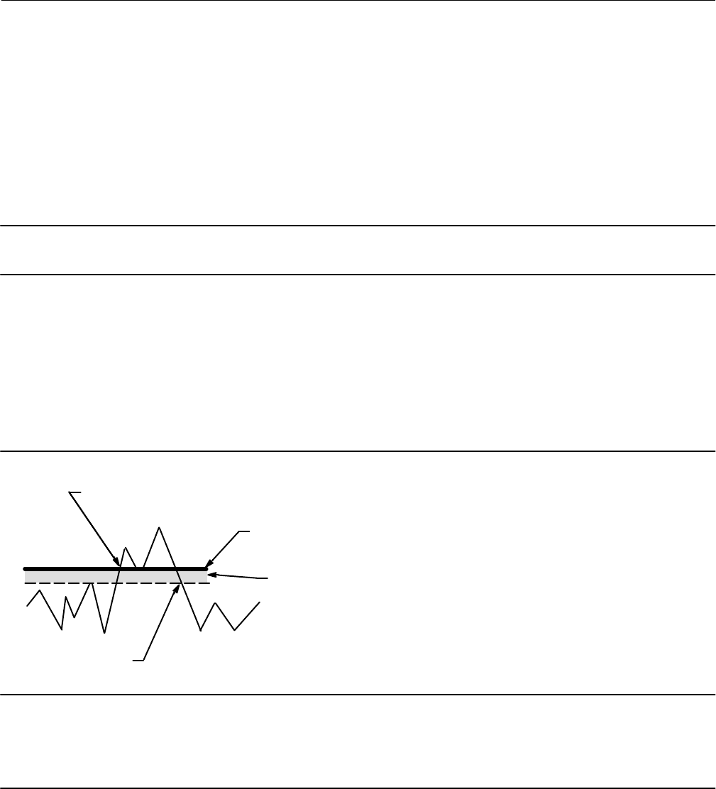
Instruction Manual
D103557X012
Device Information, Diagnostics, and Alerts
January 2015
50
Pressure
D Supply Pressure Alert—This alert is active if the supply pressure falls below the supply pressure alert point.
D End Point Pressure Deviation Alert—This alert is active if the instrument is in pressure control and the pressure is not
tracking the set point within the configured deviation allowance.
Travel
Note
The Travel Alert Deadband applies to the Travel Deviation Alert as well as the Travel Alert Hi, Lo, Hi Hi, and Lo Lo.
D Travel Deviation Alert—If the difference between the Travel Target and the Travel exceeds the Travel Deviation Alert
Point for more than the Travel Deviation Time, the Travel Deviation Alert is active. It remains active until the
difference between the travel target and the Travel is less than the Travel Deviation Alert Point minus the Travel
Alert Deadband.
D Travel Alert Hi—This alert is active when the Travel exceeds the Travel Alert Hi Point. Once the alert is active, the
alert will clear when the Travel falls below the Travel Alert Hi Point minus the Travel Alert Deadband. See figure 5‐1.
Figure 5‐1. Travel Alert Deadband
ALERT IS CLEARED
ALERT IS SET
TRAVEL ALERT
HIGH POINT
TRAVEL ALERT
DEADBAND
A6532
Note
The Travel Alert Hi Hi and Travel Alert Lo Lo points are used to calculate the stroke time in the event of a demand. The values must
be set to 99% and 1% respectively, however it is not necessary to enable the alert. Stroke time can be read from the device with
ValveLink software.
D Travel Alert Hi Hi—This alert is active when the Travel exceeds the Travel Alert Hi Hi Point. Once the alert is active,
the alert will clear when the Travel falls below the Travel Alert Hi Hi Point minus the Travel Alert Deadband.
D Travel Alert Lo—This alert is active when the Travel is below the Travel Alert Lo Point. Once the alert is active, the
alert will clear when the Travel exceeds the Travel Alert Lo Point plus the Travel Alert Deadband.

Instruction Manual
D103557X012
Device Information, Diagnostics, and Alerts
January 2015
51
D Travel Alert Lo Lo—This alert is active when the Travel is below the Travel Alert Lo Lo Point. Once the alert is active,
the alert will clear when the Travel exceeds the Travel Alert Lo Lo Point plus the Travel Alert Deadband.
D Travel Cutoff Hi Alert—This alert is active when the Travel exceeds the Hi Cutoff Point.
D Travel Cutoff Lo Alert—This alert is active when the Travel falls below the Lo Cutoff Point.
D Integrator Saturated High Alert—This alert is active if the instrument integrator is saturated at the high extreme.
D Integrator Saturated Low Alert—This alert is active if the instrument integrator is saturated at the low extreme.
D Pressure Fallback Active Alert—This alert is active when the instrument has detected a problem with the travel
feedback and is now controlling the output like an I/P transducer.
CAUTION
If a Valve Stuck alert is active, there may be potential energy stored in the valve and actuator assembly. Sudden release of
this energy may cause the valve to suddenly open or close, resulting in equipment damage.
D Valve Stuck—A partial stroke test has failed.
If the valve sticks while performing the partial stroke test, the digital valve controller will not fully exhaust or fill the
actuator pressure in its attempt to complete the partial stroke. Rather, the instrument will abort the test and this alert
will be active. It is recommended that the Travel Deviation alert also be enabled and configured. The Valve Stuck alert
will be active if either the Travel Deviation alert is active or if the actuator pressure reaches the Partial Stroke Pressure
Limit.
Travel History
D Cycle Count High Alert—This alert is active if the Cycle Counter exceeds the Cycle Count Alert Point. The Cycle Count
records the number of times the travel changes direction when it is outside of the deadband. To clear the alert, set
the Cycle Counter to a value less than the alert point.
D Travel Accumulator High Alert—This alert is active if the Travel Accumulator exceeds the Travel Accumulator Alert
Point. The Travel Accumulator totalizes the travel of the valve when the deadband is exceeded. To clear the alert,
set the Travel Accumulator to a value less than the alert point.
Note
The Cycle Count / Travel Accumulator Deadband applies to both the Cycle Count High Alert and the Travel Accumulator High
Alert.
The deadband is the percent (%) of ranged travel around a travel reference point. The travel reference point gets
reestablished to the point of travel reversal that occurs outside of the deadband. The deadband must be exceeded
before a change in travel direction will be counted as a cycle and the accumulated travel (up to the point of travel
reversal) is added to the total accumulation. See figure 5‐2.
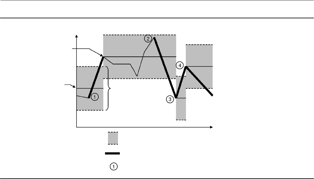
Instruction Manual
D103557X012
Device Information, Diagnostics, and Alerts
January 2015
52
Figure 5‐2. Cycle Counter and Travel Accumulator Deadband Example (set at 10%)
DEADBAND (+/- 5%)
DEADBAND EXCEEDED, NEW
REFERENCE POINT ESTABLISHED
CYCLE COUNTER INCREMENTS
DEADBAND
REFERENCE POINT
DEADBAND
DARK SEGMENTS REPRESENT THE AMOUNT OF TRAVEL
THAT WILL BE ADDED TO THE TRAVEL ACCUMULATOR
TIME
VALVE POSITION
E1473
Alert Record
D Alert Record Not Empty Alert—This alert is active when there are 1 or more alerts stored in the alert record.
D Alert Record Full Alert—This alert is active when the alert record is full. Additional alerts that are detected will not be
saved to the alert record until the alert record is cleared.
Status
D Calibration in Progress Alert—This alert is active when calibration is in progress.
D AutoCal in Progress Alert—This alert is active when auto calibration is in progress.
D Diagnostic in Progress Alert—This alert is active when a diagnostic test is in progress.
D Diagnostic Data Available Alert—This alert is active when diagnostic data has been collected and is being stored in
the instrument.
D Tripped by the LCP—The DVC6200 SIS is in the tripped position as a result of someone pressing the trip button on
the local control panel. This alert will automatically clear only after the valve returns to the normal state.
D SIS Locked in Safety Position—The DVC6200 SIS is in the tripped position.

Instruction Manual
D103557X012
Device Information, Diagnostics, and Alerts
January 2015
53
Diagnostics
Stroke Valve
Follow the prompts on the Field Communicator display to select from the following:
D Done—Select this if you are done. All ramping is stopped when DONE is selected.
D Ramp Open—ramps the travel toward open at the rate of 1.0% per second of the ranged travel.
D Ramp Closed—ramps the travel toward closed at the rate of 1.0% per second of the ranged travel.
D Ramp to Target—ramps the travel to the specified target at the rate of 1.0% per second of the ranged travel.
D Step to Target—steps the travel to the specified target.
Partial Stroke Test
WARNING
During the partial stroke test the valve will move. To avoid personal injury and property damage caused by the release of
pressure or process fluid, when used in an application where the valve is normally closed, provide some temporary means
of control for the process.
The Partial Stroke Test allows DVC6200 SIS digital valve controllers to perform a Valve Signature type of test while the
instrument is in service and operational. In some applications, it is important to be able to exercise and test the valve
to verify that it will operate when commanded. This feature allows the user to partially stroke the valve while
continually monitoring the input signal. If a demand arises, the test is aborted and the valve moves to its commanded
position. The partial stroke valve travel is configurable between 1 and 30% maximum travel, in 0.1% increments. Data
from the last partial stroke test is stored in the instrument memory for retrieval by ValveLink software.
The Partial Stroke Test allows you to perform a partial, 10%, stroke test (standard) or a custom stroke test. With the
custom stroke test, the stroke may be extended up to 30%. Be sure to check plant guidelines before performing a
custom stroke test. The purpose of this test is to ensure that the valve assembly moves upon demand.
A partial stroke test can be initiated when the valve is operating in its normal (not tripped) state. For energizetotrip
(ETT) applications, the normal state is 4 mA. For deenergizetotrip (DETT) applications, the normal state is 20 mA
(pointtopoint mode) or 24 VDC (multidrop mode).
When enabled, a partial stroke test may be initiated by the device (as a scheduled, automatic partial stroke test), a
local pushbutton, the LCP100, a Field Communicator, or ValveLink software.
D Automatic (Scheduled)
The Auto Partial Stroke Test allows the partial stroke test to be scheduled by the DVC6200 SIS. The test is scheduled in
number of hours between tests. Any power cycle will reset the test clock timer.
D Local Pushbutton
A partial stroke test command may be sent to the digital valve controller using a set of contacts wired to the auxiliary
+/- terminals. To perform a test, the contacts must be closed for 3 to 10 seconds and then opened. To abort the test,
close the contacts for 1 second. The last set of diagnostic data is stored in the instrument memory for later retrieval via
ValveLink software.

Instruction Manual
D103557X012
Device Information, Diagnostics, and Alerts
January 2015
54
D Local Control Panel
The LCP100 local control panel is wired directly to the DVC6200 SIS digital valve controller.
The black “Valve Test” push button (see figure 5‐3) allows the valve to perform the configured partial stroke test.
- Press and hold for 3 to 10 seconds
The test can be overridden by the “Valve Close” button, “Valve Open” button, or if an emergency demand occurs.
Figure 5‐3. Local Control Panel
PRESS TO PERFORM THE
CONFIGURED PARTIAL
STROKE TEST
D Field Communicator
1. Connect the Field Communicator to the LOOP terminals on the digital valve controller.
2. Turn on the Field Communicator.
3. From the Online menu, select Service Tools > Diagnostics > Partial Stroke Test.
4. Select either Standard (10%) or Custom. With the Custom Stroke Test, the stroke may be entered up to 30% with
configurable stroking speed and pause time.
5. The currently configured Stroke, Stroking Speed, and Pause Time is displayed. Choose “Yes” to run the test using
these values. Choose “No” to modify the values. The default value for Stroke Speed is 0.25%/second.
6. The valve begins to move and the actual travel reported by the digital valve controller is displayed on the Field
Communicator.
7. Once the valve has reached the endpoint, check that the valve has reached the desired set point. The valve should
return to its original position.

Instruction Manual
D103557X012
Device Information, Diagnostics, and Alerts
January 2015
55
Demand Mode Tests
The following steps assume the use of single acting spring and diaphragm actuators or double‐acting spring assist
piston actuators.
Perform the following steps to confirm valve operation:
D Point‐to‐Point Mode (DVC6200 SIS powered with 4-20 mA current source)
If the DVC6200 SIS is in series with a solenoid valve,
1. Disconnect the power from the solenoid valve, but maintain the 20 mA current to the digital valve controller.
The valve should move to its “fail safe” position.
2. Maintain power to the solenoid valve and adjust the current to the digital valve controller from
20 mA to 4 mA. The valve should move to its “fail safe” position.
3. Remove power from the solenoid valve and adjust the current to the digital valve controller from 20 mA to
4 mA. The valve should go to its “fail safe” position.
If a solenoid is not used with a DVC6200 SIS,
1. Adjust the current to the digital valve controller from 20 mA to 4 mA. The valve should move to its “fail safe”
position.
Note
The above tests are applicable for single‐acting direct relay A and C. If single‐acting reverse relay B is used adjust the current from 4
mA (normal state) to 20 mA (trip state).
D Multi‐drop Mode (DVC6200 SIS is powered by a 24 VDC power source)
If the DVC6200 SIS is pneumatically in series with a solenoid valve, and shares a single power source,
1. Disconnect power to both devices. The valve should go to its “fail safe” position.
If the DVC6200 SIS is pneumatically in series with a solenoid valve, with independent power sources,
1. Connect a 24 VDC power supply to the solenoid valve and a second 24 VDC power supply to the DVC6200 SIS.
2. Disconnect the solenoid valve power supply, but maintain the power supply to the DVC6200 SIS. The valve
should go to its “fail safe” position quickly.
3. Maintain the power supply to the solenoid valve and disconnect the DVC6200 SIS power supply. The valve
should go to its “fail safe” position, although not as quickly as it does in the previous scenario.
If DVC6200 SIS is alone, without a solenoid valve,
1. Disconnect power to the digital valve controller. The valve should go to its “fail safe” position.
Note
The above tests are applicable for single‐acting direct relay A and C.

Instruction Manual
D103557X012
Device Information, Diagnostics, and Alerts
January 2015
56
D If the LCP100 is used, conduct the following tests:
Successful Partial Stroke Test
1. Press the “Valve Test” (black) push button for more than 3 seconds (but less than 10 seconds).
2. Observe that the green light starts flashing when the valve starts moving.
3. Observe that the valve moves no more than the configured PST travel limit.
4. Observe that the valve returns to the normal operating position and the green light comes on solid.
Manually Aborted Partial Stroke Test
1. Press the “Valve Test” (black) push button for more than 3 seconds (but less than 10 seconds).
2. Observe that the green light starts flashing when the valve starts moving.
3. Before the valve reaches the travel limit of the configured partial stroke test, press the “Valve Test” push
button, or the push button next to the green light.
4. Observe that the valve immediately returns to the normal operating position and the green light comes on
solid.
Emergency Demand through the Logic Solver
1. Reduce the current to the DVC6200 SIS to 4 mA for de‐energize to trip operation.
Note
You may remove the power completely; however, the lights in step 3 will be off. Without power to the DVC6200 SIS, the LCP100
cannot function.
2. Observe that the valve moves to its fail safe state.
3. Observe that the red light comes on solid and the yellow light stays off (valve is not ready to open).
4. Press the push button next to the green light and observe that the valve does not move.
5. Increase the current to the DVC6200 SIS to 20 mA and observe that the valve remains in its fail safe state.
6. Observe that the red light stays on solid and the yellow light comes on solid (ready to reset).
7. Press the push button next to the green light.
8. Observe that the green light starts flashing, then becomes solid and the red light is off.
Emergency Demand through Local Control Panel
1. Press the push button next to the red light.
2. Observe that the valve moves to it fail safe position.
3. Observe that the red light starts flashing, then becomes solid and the yellow light comes on solid (ready to
reset).
4. Press the push button next to the green light.
5. Observe that the red light goes off, the valve moves to its normal operating position, and the green light
comes on solid.

Instruction Manual
D103557X012
Device Information, Diagnostics, and Alerts
January 2015
57
Solenoid Valve Health Monitoring
The following steps assume the use of a single‐acting actuator with a solenoid valve installed. The DVC6200 SIS digital
valve controller, with single‐acting, direct relay C, must be powered separately from the solenoid. The unused output
of the DVC6200 SIS must be connected between the solenoid and the actuator as described in the Installation section.
The relay configuration selection must be “special application” and ValveLink software must have the triggered profile
enabled.
1. When allowed by the Logic Solver, momentarily remove and then restore power to the solenoid (typically 100 to
200 milliseconds). This process should occur quickly enough that the valve assembly does not move when the
solenoid is de‐energized.
2. With ValveLink software, upload the diagnostic data from the triggered profile menu.
3. Examine the graph and observe that there was a change in the pressure reading downstream of the solenoid.
Variables
Field Communicator Service Tools > Variables (3-4)
The Variables section provides current values of the instrument variables. Below is a list of the variables available for
viewing:
D Write Protection (also provides a procedure to enable/disable)
D Instrument Mode (also provides a procedure to place in/out of service)
D Analog Input
D Setpoint
D Travel
D Drive Signal
D Input Characterization (also provides a procedure to modify)
D Cycle Counter
D Travel Accumulator
D Supply Pressure
D Actuator Pressure(s)
D Instrument Temperature
D Travel Counts (this is the raw travel sensor reading used for advanced adjustments)
D Maximum Recorded Temperature
D Minimum Recorded Temperature
D Number of Power Ups
D Days Powered Up

Instruction Manual
D103557X012
Device Information, Diagnostics, and Alerts
January 2015
58

Instruction Manual
D103557X012
Maintenance and Troubleshooting
January 2015
59
Section 6 Maintenance and Troubleshooting66
The DVC6200 SIS digital valve controller enclosure is rated Type 4X and IP66, therefore periodic cleaning of internal
components is not required. If the DVC6200 SIS is installed in an area where the exterior surfaces tend to get heavily
coated or layered with industrial or atmospheric contaminants, however, it is recommended that the vent (key 52) be
periodically inspected to ensure it is fully open. If the vent appears to be clogged, it can be removed, cleaned and
replaced. Lightly brush the exterior of the vent to remove contaminants and run a mild water/detergent solution
through the vent to ensure it is fully open. Allow the vent to dry before reinstalling.
WARNING
Personal injury or property damage can occur from cover failure due to overpressure. Ensure that the housing vent
opening is open and free of debris to prevent pressure buildup under the cover.
WARNING
To avoid static discharge from the plastic cover when flammable gases or dust are present, do not rub or clean the cover
with solvents. To do so could result in a spark that may cause the flammable gases or dust to explode, resulting in personal
injury or property damage. Clean with a mild detergent and water only.
WARNING
Avoid personal injury or property damage from sudden release of process pressure or bursting of parts. Before performing
any maintenance procedures on the DVC6200 SIS digital valve controller:
D Always wear protective clothing, gloves, and eyewear.
D Do not remove the actuator from the valve while the valve is still pressurized.
D Disconnect any operating lines providing air pressure, electric power, or a control signal to the actuator. Be sure the
actuator cannot suddenly open or close the valve.
D Use bypass valves or completely shut off the process to isolate the valve from process pressure. Relieve process pressure
from both sides of the valve.
D Use lock‐out procedures to be sure that the above measures stay in effect while you work on the equipment.
D Check with your process or safety engineer for any additional measures that must be taken to protect against process
media.
D Vent the pneumatic actuator loading pressure and relieve any actuator spring precompression so the actuator is not
applying force to the valve stem; this will allow for the safe removal of the stem connector.
WARNING
When using natural gas as the supply medium, or for explosion proof applications, the following warnings also apply:
D Remove electrical power before removing the housing cap. Personal injury or property damage from fire or explosion
may result if power is not disconnected before removing the cap.
D Remove electrical power before disconnecting any of the pneumatic connections.
D When disconnecting any of the pneumatic connections or any pressure retaining part, natural gas will seep from the
unit and any connected equipment into the surrounding atmosphere. Personal injury or property damage may result

Instruction Manual
D103557X012
Maintenance and Troubleshooting
January 2015
60
from fire or explosion if natural gas is used as the supply medium and appropriate preventive measures are not taken.
Preventive measures may include, but are not limited to, one or more of the following: ensuring adequate ventilation
and the removal of any ignition sources.
D Ensure that the cover is correctly installed before putting this unit back into service. Failure to do so could result in
personal injury or property damage from fire or explosion.
CAUTION
When replacing components, use only components specified by the factory. Always use proper component replacement
techniques, as presented in this manual. Improper techniques or component selection may invalidate the approvals and
the product specifications, as indicated in table 1‐1, and may also impair operations and the intended function of the
device.
Because of the diagnostic capability of the DVC6200 SIS, predictive maintenance is available through the use of
ValveLink software. Using the digital valve controller, valve and instrument maintenance can be enhanced, thus
avoiding unnecessary maintenance. For information on using ValveLink software, refer to the ValveLink software
online help.
Removing the Magnetic Feedback Assembly
To remove the magnet assembly from the actuator stem, perform the following basic steps.
1. Make sure that the valve is isolated from the process.
2. Remove the instrument terminal box cover.
3. Disconnect the field wiring from the terminal board.
4. Shut off the instrument air supply.
5. Disconnect the pneumatic tubing and remove the DVC6200 SIS or the DVC6215 from the actuator.
6. Remove the screws holding the magnet assembly to the connector arm.
When replacing the instrument, be sure to follow the mounting guidelines in the Installation section. Setup and
calibrate the instrument prior to returning to service.
Module Base Maintenance
The digital valve controller contains a module base consisting of the I/P converter, printed wiring board assembly, and
pneumatic relay. The module base may be easily replaced in the field without disconnecting field wiring or tubing.
Tools Required
Table 6‐1 lists the tools required for maintaining the DVC6200 SIS digital valve controller.
Table 6‐1. Tools Required
Tool Size Component
Phillips Screwdriver
Hex key
Hex key
Hex key
Hex key
5 mm
1.5 mm
2.5 mm
6 mm
Relay, printed wiring board assembly, and cover
screws
Terminal box screw
Terminal box cover screw
I/P converter screws
Module base screws

Instruction Manual
D103557X012
Maintenance and Troubleshooting
January 2015
61
Component Replacement
When replacing any of the components of the DVC6200 SIS, the maintenance should be performed in an instrument
shop whenever possible. Make sure that the electrical wiring and pneumatic tubing is disconnected prior to
disassembling the instrument.
Removing the Module Base
Refer to figure 7‐2 or 7‐4 for key number locations.
WARNING
To avoid personal injury or equipment damage from bursting of parts, turn off the supply pressure to the digital valve
controller and bleed off any excess supply pressure before attempting to remove the module base assembly from the
housing.
1. Unscrew the four captive screws in the cover (key 43) and remove the cover from the module base (key 2).
2. Using a 6 mm hex socket wrench, loosen the three‐socket head screws (key 38). These screws are captive in the
module base by retaining rings (key 154).
Note
The module base is linked to the housing by two cable assemblies. Disconnect these cable assemblies after you pull the module
base out of the housing.
3. Pull the module base straight out of the housing (key 1). Once clear of the housing, swing the module base to the
side of the housing to gain access to the cable assemblies.
4. The digital valve controller/base unit has two cable assemblies, shown in figure 6‐1, which connect the module
base, via the printed wiring board assembly, travel sensor and the terminal box. Disconnect these cable assemblies
from the printed wiring board assembly on the back of the module base.
Figure 6‐1. Printed Wiring Board Cable Connections
HOUSING
W9924-1-SIS CABLE TO TRAVEL SENSOR
PRINTED WIRING
BOARD ASSEMBLY
CABLE
TO TERMINAL BOX
TERMINAL
BOX
MODULE BASE ASSEMBLY

Instruction Manual
D103557X012
Maintenance and Troubleshooting
January 2015
62
Replacing the Module Base
Refer to figure 7‐2 or 7‐4 for key number locations.
CAUTION
To avoid affecting performance of the instrument, take care not to damage the module base seal or guide surface. Do not
bump or damage the bare connector pins on the PWB assembly. Damaging either the module base or guide surface may
result in material damage, which could compromise the instruments ability to maintain a pressure seal.
Note
To avoid affecting performance of the instrument, inspect the guide surface on the module and the corresponding seating area in
the housing before installing the module base assembly. These surfaces must be free of dust, dirt, scratches, and contamination.
Ensure the module base seal is in good condition. Do not reuse a damaged or worn seal.
1. Ensure the module base seal (key 237) is properly installed in the housing (key 1). Ensure the O‐ring (key 12) is in
place on the module base assembly.
2. Connect the travel sensor and terminal box cable assemblies to the PWB assembly (key 50). Orientation of the
connector is required.
3. Insert the module base (key 2) into the housing (key 1).
4. Install three socket head screws (key 38) in the module base into the housing. If not already installed, press three
retaining rings (key 154) into the module base. Evenly tighten the screws in a crisscross pattern to a final torque of
16 NSm (138 lbfSin).
WARNING
Personal injury, property damage, or disruption of process control can result if the cable assemblies/wiring are damaged
when attaching the cover to the module base assembly
Ensure that the cable assemblies/wiring are positioned in the cavity of the module base so they do not get compressed or
damaged when attaching the cover to the module base assembly in step 5.
5. Attach the cover (key 43) to the module base assembly.
Submodule Maintenance
The module base of the DVC6200 SIS contains the following submodules: I/P converter, PWB assembly, and
pneumatic relay. If problems occur, these submodules may be removed from the module base and replaced with new
submodules. After replacing a submodule, the module base may be put back into service.
CAUTION
Exercise care when performing maintenance on the module base. Reinstall the cover to protect the I/P converter and
gauges when servicing other submodules.
In order to maintain accuracy specifications, do not strike or drop the I/P converter during submodule maintenance.
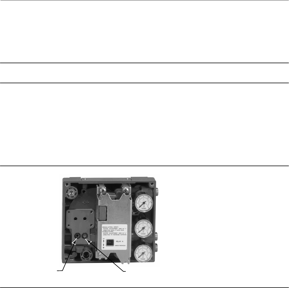
Instruction Manual
D103557X012
Maintenance and Troubleshooting
January 2015
63
I/P Converter
Refer to figure 7‐2 or 7‐4 for key number locations. The I/P converter (key 41) is located on the front of the module
base.
Note
After I/P converter submodule replacement, calibrate the digital valve controller to maintain accuracy specifications.
Replacing the I/P Filter
A screen in the supply port beneath the I/P converter serves as a secondary filter for the supply medium. To replace this
filter, perform the following procedure:
1. Remove the I/P converter (key 41) and shroud (key 169) as described in the Removing the I/P Converter procedure.
2. Remove the screen (key 231) from the supply port.
3. Install a new screen in the supply port as shown in figure 6‐2.
Figure 6‐2. I/P Filter Location
SCREEN (FILTER) LOCATED IN
I/P CONVERTER SUPPLY PORT
O‐RING LOCATED IN I/P
CONVERTER OUTPUT PORT
W8072
4. Inspect the O‐ring (key 39) in the I/P output port. if necessary, replace it.
5. Reinstall the I/P converter (key 41) and shroud (key 169) as described in the Replacing the I/P Converter procedure.
Removing the I/P Converter
1. Remove the front cover (key 43), if not already removed.
2. Refer to figure 6‐3. Using a 2.5 mm hex socket wrench, remove the four socket‐head screws (key 23) that attach the
shroud (key 169) and I/P converter (key 41) to the module base (key 2).
3. Remove the shroud (key 169); then pull the I/P converter (key 41) straight out of the module base (key 2). Be
careful not to damage the two electrical leads that come out of the base of the I/P converter.
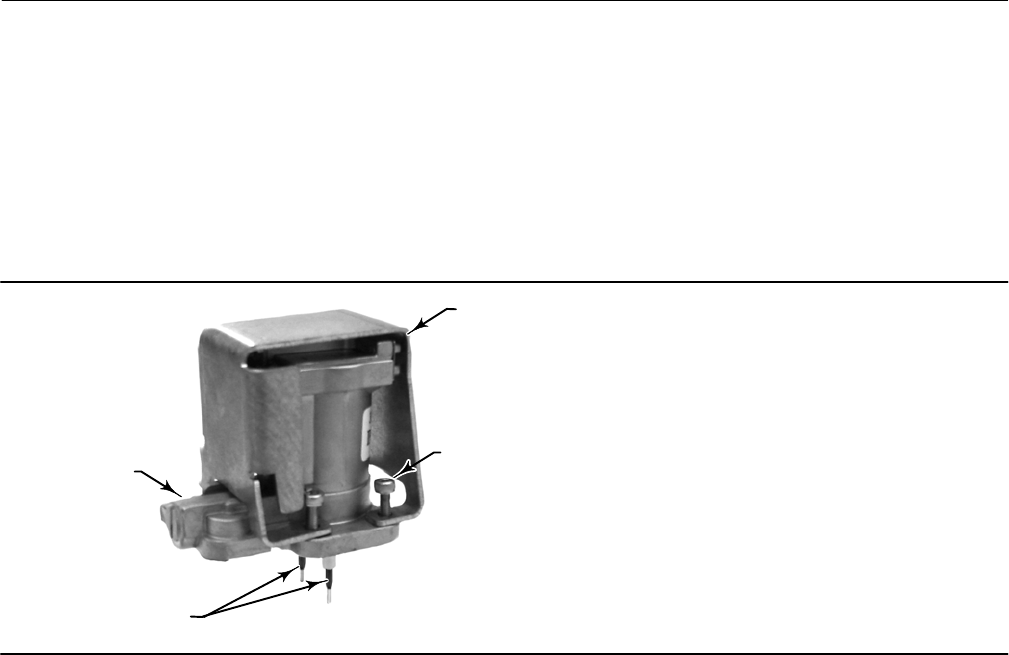
Instruction Manual
D103557X012
Maintenance and Troubleshooting
January 2015
64
4. Ensure that the O‐ring (key 39) and screen (key 231) stay in the module base and do not come out with the I/P
converter (key 41).
Replacing the I/P Converter
1. Refer to figure 6‐2. Inspect the condition of the O‐ring (key 39) and screen (key 231) in the module base (key 2).
Replace them, if necessary. Apply silicone lubricant to the O‐rings.
2. Ensure the two boots (key 210) shown in figure 6‐3 are properly installed on the electrical leads.
W9328
SOCKET‐HEAD
SCREWS (4)
(KEY 23)
SHROUD
(KEY 169)
I/P CONVERTER
(KEY 41)
BOOTS
(KEY 210)
Figure 6‐3. I/P Converter
3. Install the I/P converter (key 41) straight into the module base (key 2), taking care that the two electrical leads feed
into the guides in the module base. These guides route the leads to the printed wiring board assembly submodule.
4. Install the shroud (key 169) over the I/P converter (key 41).
5. Install the four socket‐head screws (key 23) and evenly tighten them in a crisscross pattern to a final torque of
1.6 NSm (14 lbfSin).
6. After replacing the I/P converter, calibrate travel or perform touch‐up calibration to maintain accuracy
specifications.
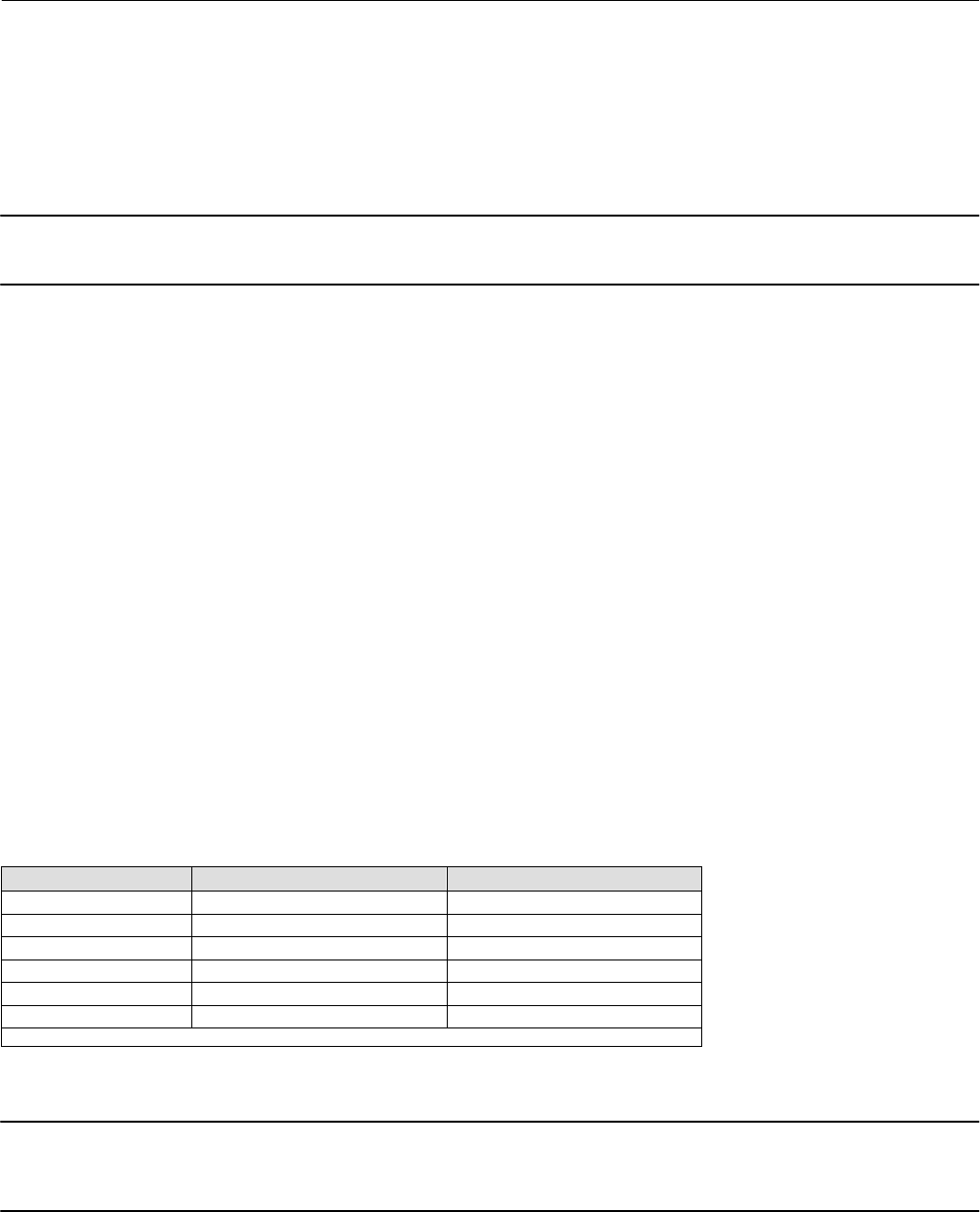
Instruction Manual
D103557X012
Maintenance and Troubleshooting
January 2015
65
Printed Wiring Board (PWB) Assembly
Refer to figure 7‐2 or 7‐4 for key number locations. The PWB assembly (key 50) is located on the back of the module
base assembly (key 2).
Note
If the PWB assembly submodule is replaced, calibrate and configure the digital valve controller to maintain accuracy specifications.
Removing the Printed Wiring Board Assembly
1. Separate the module base from the housing by performing the Removing the Module Base procedure.
2. Remove three screws (key 33).
3. Lift the PWB assembly (key 50) straight out of the module base (key 2).
4. Ensure that the O‐rings (key 40) remain in the pressure sensor bosses on the module base assembly (key 2) after the
PWB assembly (key 50) has been removed.
Replacing the Printed Wiring Board Assembly and Setting the DIP Switch
1. Apply silicone lubricant to the pressure sensor O‐rings (key 40) and install them on the pressure sensor bosses in the
module base assembly.
2. Properly orient the PWB assembly (key 50) as you install it into the module base. The two electrical leads from the
I/P converter (key 41) must guide into their receptacles in the PWB assembly and the pressure sensor bosses on the
module base must fit into their receptacles in the PWB assembly.
3. Push the PWB assembly (key 50) into its cavity in the module base.
4. Install and tighten three screws (key 33) to a torque of 1 NSm (10.1 lbfSin).
5. Set the DIP switch on the PWB assembly according to table 6‐2.
Table 6‐2. DIP Switch Configuration(1)
Switch Label Operational Mode DIP Switch Position
PT-PT 420 mA PointtoPoint Loop LEFT
Multi 24 VDC MultiDrop Loop RIGHT
Hardware Shutdown Enabled LEFT
Hardware Shutdown Disabled RIGHT
Trip Current Low (DETT) De-energize to trip LEFT
Trip Current High (ETT) Energize to trip RIGHT
1. Refer to figure 6‐4 for switch location.
Note
DVC6200 SIS instruments in PT-PT mode require the Hardware Shutdown Switch be Enabled for FMEDA failure rates to be valid for
420 mA operation.
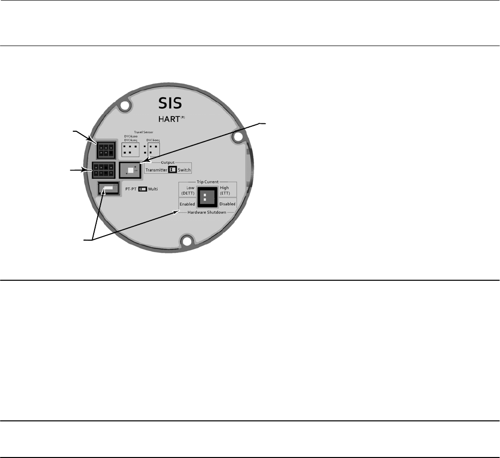
Instruction Manual
D103557X012
Maintenance and Troubleshooting
January 2015
66
X0436
Figure 6‐4. Printed Wiring Board (PWB) Connections and Settings
TRANSMITTER / SWITCH
SELECTION
TRAVEL SENSOR
CONNECTOR
TERMINAL BOX
CONNECTOR
OPERATIONAL
MODE SELECTIONS
6. Reassemble the module base to the housing by performing the Replacing the Module Base procedure.
7. Setup and calibrate the digital valve controller.
Pneumatic Relay
Refer to figure 7‐2 or 7‐4 for key number locations. The pneumatic relay (key 24) is located on the front of the module
base.
Note
After relay submodule replacement, calibrate the digital valve controller to maintain accuracy specifications.
Removing the Pneumatic Relay
1. Loosen the four screws that attach the relay (key 24) to the module base. These screws are captive in the relay.
2. Remove the relay.
Replacing the Pneumatic Relay
1. Visually inspect the holes in the module base to ensure they are clean and free of obstructions. If cleaning is
necessary, do not enlarge the holes.
2. Apply silicone lubricant to the relay seal and position it in the grooves on the bottom of the relay as shown in
figure 6‐5. Press small seal retaining tabs into retaining slots to hold relay seal in place.

Instruction Manual
D103557X012
Maintenance and Troubleshooting
January 2015
67
Figure 6‐5. Pneumatic Relay Assembly
W8074
RELAY SEAL
3. Position the relay (with shroud) on the module base. Tighten the four screws, in a crisscross pattern, to a final
torque of 2 NSm (20.7 lbfSin).
4. Using the Field Communicator, verify that the value for Relay Type parameter matches the relay type installed.
5. After replacing the relay and verifying the relay type, calibrate travel or perform touch‐up calibration to maintain
accuracy specifications
Gauges, Pipe Plugs, or Tire Valves
Depending on the options ordered, the DVC6200 SIS or DVC6205 SIS will be equipped with either gauges (key 47),
pipe plugs (key 66), or tire valves (key 67). Single‐acting direct instruments will also have a screen (key 236, figure 7‐3).
These are located on the top of the module base next to the relay.
Perform the following procedure to replace the gauges, tire valves, or pipe plugs. Refer to figure 7‐2 and 7‐3 for key
number locations.
1. Remove the front cover (key 43).
2. Remove the gauge, pipe plug, or tire valve as follows:
For gauges (key 47), the flats are on the gauge case. Use a wrench on the flats of the gauge to remove the gauge from
the module base. For double‐acting instruments, to remove the supply gauge remove one of the output gauges.
For pipe plugs (key 66) and tire valves (key 67), use a wrench to remove these from the module base.
3. Apply zinc based anti-seize sealant (key 64) to the threads of the replacement gauges, pipe plugs, or tire valves.
4. Using a wrench, screw the gauges, pipe plugs, or tire valves into the module base.
Terminal Box
Refer to figure 7‐2 or 7‐4 for key number locations.
The terminal box is located on the housing and contains the terminal strip assembly for field wiring connections.
Note
The DVC6205 SIS feedback connections terminal box (shown to the right in figure 6‐6) is not a replaceable part. Do not remove
the tamper proof paint on the screw.
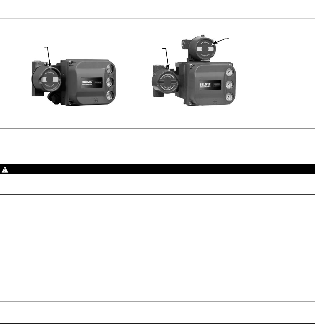
Instruction Manual
D103557X012
Maintenance and Troubleshooting
January 2015
68
Figure 6‐6. Terminal Boxes
FEEDBACK CONNECTIONS
TERMINAL BOX;
NOT REPLACEABLE
DVC6205 SIS
DVC6200 SIS
MAIN TERMINAL
BOX
MAIN TERMINAL BOX
X0338-SIS X0379-SIS
Removing the Terminal Box
WARNING
To avoid personal injury or property damage caused by fire or explosion, remove power to the instrument before removing
the terminal box cover in an area which contains a potentially explosive atmosphere or has been classified as hazardous.
1. Loosen the set screw (key 58) in the cap (key 4) so that the cap can be unscrewed from the terminal box.
2. After removing the cap (key 4), note the location of field wiring connections and disconnect the field wiring from
the terminal box.
3. Separate the module base from the housing by performing the Removing the Module Base procedure.
4. Disconnect the terminal box wiring connector from the PWB assembly (key 50).
5. Remove the screw (key 72). Pull the terminal box assembly straight out of the housing.
Replacing the Terminal Box
Note
Inspect all O‐rings for wear and replace as necessary.
1. Apply lubricant, silicone sealant to the O‐ring (key 34) and install the O‐ring over the stem of the terminal box.
2. Insert the terminal box assembly stem into the housing until it bottoms out. Position the terminal box assembly so
that the hole for the screw (key 72) in the terminal box aligns with the threaded hole in the housing. Install the
screw (key 72).
3. Connect the terminal box wiring connector to the PWB assembly (key 50). Orientation of the connector is required.
4. Reassemble the module base to the housing by performing the Replacing the Module Base procedure.
5. Reconnect the field wiring as noted in step 2 in the Removing the Terminal Box procedure.

Instruction Manual
D103557X012
Maintenance and Troubleshooting
January 2015
69
6. Apply lubricant, silicone sealant to the O‐ring (key 36) and install the O‐ring over the 2‐5/8 inch threads of the
terminal box. Use of a tool is recommended to prevent cutting the O‐ring while installing it over the threads.
7. Apply lithium grease (key 63) to the 2‐5/8 inch threads on the terminal box to prevent seizing or galling when the
cap is installed.
8. Screw the cap (key 4) onto the terminal box.
9. Install a set screw (key 58) into the cap (key 4). Loosen the cap (not more than 1 turn) to align the set screw over
one of the recesses in the terminal box. Tighten the set screw (key 58).
Troubleshooting
If communication or output difficulties are experienced with the instrument, refer to the troubleshooting chart in
table 6‐3. Also see the DVC6200 SIS Technical Support Checklist on page 72.
Checking Voltage Available
WARNING
Personal injury or property damage caused by fire or explosion may occur if this test is attempted in an area which contains
a potentially explosive atmosphere or has been classified as hazardous.
To check the Voltage Available at the instrument, perform the following:
1. Connect the equipment in figure 2‐2 to the field wiring in place of the FIELDVUE instrument.
2. Set the control system to provide maximum output current.
3. Set the resistance of the 1 kilohm potentiometer shown in figure 2‐2 to zero.
4. Record the current shown on the milliammeter.
5. Adjust the resistance of the 1 kilohm potentiometer until the voltage read on the voltmeter is 10.0 volts.
6. Record the current shown on the milliammeter.
7. If the current recorded in step 6 is the same as that recorded in step 4 (± 0.08 mA), the voltage available is
adequate.
8. If the voltage available is inadequate, refer to Wiring Practices in the Installation section.
Restart Processor
This is a “soft” reset of the device. This procedure can only be performed while the instrument is out of service. A soft
reset will immediately put into effect changes that have been sent to the instrument. Also, if the device is configured
to shutdown on an alert, the soft reset will clear the shutdown.

Instruction Manual
D103557X012
Maintenance and Troubleshooting
January 2015
70
Table 6‐3. Instrument Troubleshooting
Symptom Possible Cause Action
1. Analog input reading at
instrument does not match
actual current provided.
1a. Control mode not Analog. 1a. Check the control mode using the Field Communicator. If in
the Digital or Test mode, the instrument receives its set point as
a digital signal. Control is not based on input current. Change
Control Mode to Analog.
1b. Low control system compliance voltage. 1b. Check system compliance voltage (see Wiring Practices in
the Installation section.
1c. Instrument shutdown due to self test failure. 1c. Check instrument status using the Field Communicator (see
Viewing Instrument Status in the Viewing Device Information
section).
1d. Analog input sensor not calibrated. 1d. Calibrate the analog input sensor (see Analog Input
Calibration in the Calibration section).
1e. Current leakage. 1e. Excessive moisture in the terminal box can cause current
leakage. Typically the current will vary randomly if this is the
case. Allow the inside of the terminal box to dry, then retest.
2. Instrument will not
communicate.
2a. Insufficient Voltage Available. 2a. Calculate Voltage Available (see Wiring Practices in the
Installation section). Voltage Available should be greater than or
equal to 10 VDC.
2b. Controller output Impedance too low. 2b. Install a HART filter after reviewing Control System
Compliance Voltage requirements (see Wiring Practices in the
Installation section).
2c. Cable capacitance too high. 2c. Review maximum cable capacitance limits (see Wiring
Practices in the Installation section).
2d. HART filter improperly adjusted. 2d. Check filter adjustment (see the appropriate HART filter
instruction manual).
2e. Improper field wiring. 2e. Check polarity of wiring and integrity of connections. Make
sure cable shield is grounded only at the control system.
2f. Controller output providing less than 4 mA to loop. 2f. Check control system minimum output setting, which should
not be less than 3.8 mA.
2g. Disconnected loop wiring cable at PWB. 2g. Verify connectors are plugged in correctly.
2h. PWB DIP switch not set properly. 2h. Check for incorrect setting or broken DIP switch on the back
of the PWB. Reset switch or replace PWB, if switch is broken. See
table 6‐2 for switch setting information
2j. PWB failure. 2j. Use a 4-20 mA current source to apply power to the
instrument. Terminal voltage across the LOOP+ and LOOP-
terminals should be 8.0 to 9.5 VDC. If the terminal voltage is not
8.0 to 9.5 VDC, replace the PWB.
2k. Polling address incorrect. 2k. Use the Field Communicator to set the polling address (refer
to the Detailed Setup section). From the Utility menu, select
Configure Communicator > Polling > Always Poll. Set the
instrument polling address to 0.
2l. Defective terminal box. 2l. Check continuity from each screw terminal to the
corresponding PWB connector pin. If necessary, replace the
terminal box assembly.
2m. Defective Field Communicator or ValveLink
modem cable.
2m. If necessary, repair or replace cable.
2n. ValveLink modem defective or not compatible
with PC.
2n. Replace ValveLink modem.
2p. ValveLink hardlock defective or not programmed. 2p. Replace if defective or return to factory for programming.
-continued-

Instruction Manual
D103557X012
Maintenance and Troubleshooting
January 2015
71
Table 6‐3. Instrument Troubleshooting (continued)
Symptom Possible Cause Action
3. Instrument will not
calibrate, has sluggish
performance or oscillates.
3a. Configuration errors. 3a. Verify configuration:
If necessary, set protection to None.
If Out of Service, place In Service.
Check:
Travel Sensor Motion
Tuning set
Zero Power Condition
Feedback Connection
Control mode (should be Analog)
Restart control mode (should be Analog)
3b. Restricted pneumatic passages in I/P converter. 3b. Check screen in I/P converter supply port of the module base.
Replace if necessary. If passages in I/P converter restricted,
replace I/P converter.
3c. O‐ring(s) between I/P converter ass'y missing or hard
and flattened losing seal.
3c. Replace O‐ring(s).
3d. I/P converter ass'y damaged/corroded/clogged. 3d. Check for bent flapper, open coil (continuity),
contamination, staining, or dirty air supply. Coil resistance
should be between 1680 ‐ 1860 ohms. Replace I/P assembly if
damaged, corroded, clogged, or open coil.
3e. I/P converter ass'y out of spec. 3e. I/P converter ass'y nozzle may have been adjusted. Verify
drive signal (55 to 80% for double‐acting; 60 to 85% for
single‐acting) with the valve off the stops. Replace I/P converter
assembly if drive signal is continuously high or low.
3f. Defective module base seal. 3f. Check module base seal for condition and position. If
necessary, replace seal.
3g. Defective relay. 3g. Depress relay beam at adjustment location in shroud, look
for increase in output pressure. Remove relay, inspect relay seal.
Replace relay seal or relay if I/P converter assembly is good and
air passages not blocked. Check relay adjustment.
3h. Defective 67CFR regulator, supply pressure gauge
jumps around.
3h. Replace 67CFR regulator.
4. ValveLink diagnostic tests
provide erroneous results.
4a. Defective pressure sensor. 4a. Replace PWB.
4b. Pressure sensor O‐ring missing. 4b. Replace O‐ring.
5. Field Communicator does
not turn on.
5a. Battery pack not charged. 5a. Charge battery pack.
Note: Battery pack can be charged while attached to the Field
communicator or separately. The Field Communicator is fully
operable while the battery pack is charging. Do not attempt to
charge the battery pack in a hazardous area.

Instruction Manual
D103557X012
Maintenance and Troubleshooting
January 2015
72
DVC6200 SIS Technical Support Checklist
Have the following information available prior to contacting your Emerson Process Management sales office for
support.
1. Instrument serial number as read from nameplate ________________________________________________
2. Is the digital valve controller responding to the control signal? Yes _________ No _________
If not, describe ___________________________________________________________________________
3. Measure the voltage across the “Loop -” and Loop +” terminal box screws when the commanded current is 4.0 mA
and 20.0 mA: __________V @ 4.0 mA __________V @ 20.0 mA.
(These values should be around 8.6 V @ 4.0 mA and 8.8 V @ 20 mA).
4. Is it possible to communicate via HART to the digital valve controller? Yes _________ No _________
5. What is the firmware version of the digital valve controller? ______________
6. What is the hardware version of the digital valve controller? ______________
7. Is the digital valve controller's Instrument Mode “In Service”? Yes _________ No _________
8. Is the digital valve controller's Control Mode set to “Analog”? Yes _________ No _________
9. What are the following parameter readings?
Input Signal _________ Drive Signal _________%
Supply Pressure _________ Pressure A _________ Pressure B _________
Travel Target _________% Travel _________%
10. What are the following alert readings?
Fail alerts _______________________________________________________________________________
Valve alerts _____________________________________________________________________________
Operational status ________________________________________________________________________
Alert event record entries __________________________________________________________________
11. Export ValveLink data (if available) for the device (Status Monitor, Detailed Setup, etc.).
Mounting
1. Which digital valve controller do you have? DVC6200 SIS __________ DVC6205 SIS/DVC6215 _________________
2. What Make, Brand, Style, Size, etc. actuator is the DVC6200 SIS mounted on? ______________________________
3. What is the full travel of the valve? ______________________________________________________________
4. What is the Mounting Kit part number? __________________________________________________________
5. If mounting kits are made by LBP/Customer, please provide pictures of installation.
6. Is the Mounting kit installed per the instructions? Yes _________ No _________
7. What is the safe position of the valve? Fail closed _________ Fail open _________
Instruction Manual
D103557X012
Parts
January 2015
73
Section 7 Parts77
Parts Ordering
Whenever corresponding with your Emerson Process Management sales office about this equipment, always mention
the controller serial number. When ordering replacement parts, refer to the 11‐character part number of each
required part as found in the following parts list. Part numbers are shown for kits and recommended spares only. For
part numbers not shown, contact your Emerson Process Management sales office.
WARNING
Use only genuine Fisher replacement parts. Components that are not supplied by Emerson Process Management should
not, under any circumstances, be used in any Fisher instrument. Use of components not supplied by Emerson Process
Management may void your warranty, might adversely affect the performance of the instrument, and could cause personal
injury and property damage.
Parts Kits
Kit Description Part Number
1* Fluorosilicone Elastomer Spare Parts Kit (kit contains parts to
service one digital valve controller) 19B5402X022
2* Small Hardware Spare Parts Kit (kit contains parts
to service one digital valve controller) 19B5403X012
3* Seal Screen Kit
[kit contains 25 seal screens (key 231)
and 25 O‐rings (key 39)]
Extreme Temperature option 14B5072X182
(fluorosilicone elastomers)
4* Terminal Box Kit (see figure 7‐1)
Note
Use only with replace in-kind. The following terminal boxes are
compatible only with PWB Assembly electronics hardware revision 2
(HW2).
Aluminum, with I/O Package
Extreme Temperature (fluorosilicone elastomers) 19B5401X192
Stainless Steel, with I/O Package
Extreme Temperature (fluorosilicone elastomers) 19B5401X202
5* I/P Converter Kit
For Extreme Temperature option
(fluorosilicone elastomers) 38B6041X132
Figure 7‐1. Terminal Box
X0430
Key Description
50* PWB Assembly (HW2) (see figure 7‐2 and 7‐4)
for DVC6200 SIS and DVC6205 SIS
Note
The following PWB Assemby is compatible only with the terminal box
shown in figure 7‐1. Contact your Emerson Process Management
sales office if a replacement PWB is needed.
Hardware Revision 2 (HW2), with I/O Package
For instrument level SIS
*Recommended spare parts

Instruction Manual
D103557X012
Parts
January 2015
74
Kit Description Part Number
6* Spare Module Base Assembly Kit
[kit contains module base (key 2); drive screws, qty. 2,
(key 11); shield/label (key 19); hex socket cap screw, qty. 3,
(key 38); self tapping screw, qty. 2 (key 49); pipe plug, qty. 3
(key 61); retaining ring, qty. 3 (key 154); screen (key 236);
and flame arrestors, qty. 3 (key 243)]
Aluminum GE18654X012
Stainless Steel GE18654X022
7* Spare Housing Assembly Kit
[kit contains housing (key 1); vent assembly (key 52);
seal (only included in Housing A kits) (key 288);
seal (key 237); O‐ring (key 34); O‐ring (only used
with integrally mounted regulator) (key 5)]
Aluminum
Housing A (used for GX actuator)
Extreme Temperature option
(fluorosilicone elastomers) GE48798X042
Housing B (used for all actuators except GX)
Extreme Temperature option
(fluorosilicone elastomers) GE48798X082
Stainless Steel
Housing B (used for all actuators except GX)
Extreme Temperature option
(fluorosilicone elastomers) GE48798X102
8* Spare I/P Shroud Kit
[kit contains shroud (key 169) and
hex socket cap screw, qty. 4 (key 23)] GE29183X012
9* Remote Mount Feedback Unit Kit (see figure 7‐5)
[remote housing assembly (key25); hex socket set
screw (key 58); 1/2 NPT pipe plug (key 62); wire retainer, qty 2
(key 131); terminal cover (key 255); o-ring (key 256); gasket
(Housing A only, used for GX actuator) (key 287); seal
(Housing A only, used for GX actuator) (key 288)
Housing A (used for GX actuator) GE46670X012
Housing B (used for all actuators except GX) GE40178X012
10* Feedback Array Kit
Sliding Stem (Linear)
[kit contains feedback array and hex socket cap screws, qty.2,
washer, plain, qty.2, external tooth lock washer, qty.2 (only with
aluminum feedback array kit) and alignment template.
210 mm (8-1/4 inch) kit contains feedback array and hex
socket cap screws, qty. 4,washer, plain, qty. 4, external tooth
lock washer, qty. 4 (only with aluminum feedback array kit),
alignment template and insert]. Stainless steel kits only for use
with stainless steel mounting kits.
7 mm (1/4-inch)
Aluminum GG20240X012
19 mm (3/4-inch)
Aluminum GG20240X022
Stainless steel GE65853X012
25 mm (1-inch)
Aluminum GG20240X032
Stainless steel GE65853X022
Kit Description Part Number
10* Feedback Array Kit
38 mm (1-1/2 inch)
Aluminum GG20240X042
Stainless steel GE65853X032
50 mm (2-inch)
Aluminum GG20240X052
Stainless steel GE65853X042
110 mm (4-1/8 inch)
Aluminum GG20240X082
Stainless steel GE65853X062
210 mm (8-1/4 inch)
Aluminum GG20243X012
Stainless steel GE65853X072
Rotary
[Kit contains feedback assembly, pointer assembly, travel
indicator scale and M3 machine pan head screws qty.2].
Stainless steel kits only for use with stainless steel mounting kits.
Aluminum GE71982X012
Stainless steel GE71982X022
11 Mounting Shield Kit
[kit contains shield, qty. 3 and machine
screws, qty. 6] GG05242X022
12* Gasket/Seal Kit, for use with GX actuator
[kit contains insulating gasket (key 287)
and seal (key 288)] GE45468X012
Parts List
Note
Part numbers are shown for recommended spares only. For part
numbers not shown, contact your Emerson Process Management sales
office.
Parts with footnote numbers shown are available in parts kits; see
footnote information at the bottom of the page.
Key Description
Housing (see figure 7‐2 and 7‐4)
DVC6200 SIS and DVC6205 SIS
1 Housing(7)
11 Drive Screw (2 req'd) (DVC6205 SIS only)
20 Shield (DVC6205 SIS only)
52 Vent, plastic(2)
74 Mounting Bracket (DVC6205 SIS only)
248 Screw, hex head (4 req’d) (DVC6205 SIS only)
249 Screw, hex head (4 req’d) (DVC6205 SIS only)
250 Spacer (4 req’d) (DVC6205 SIS only)
267 Standoff (2 req’d) (DVC6205 SIS only)
271 Screen(7)
287 Gasket, Housing A only (used for GX actuator) (DVC6200 SIS only)
288 Seal, Housing A only (used for GX actuator) (DVC6200 SIS only)
*Recommended spare parts
2. Available in the Small Hardware Spare Parts Kit
7. Available in the Spare Housing Assembly Kit

Instruction Manual
D103557X012
Parts
January 2015
75
Key Description Part Number
Common Parts
(see figure 7‐2, 7‐3, and 7‐4)
DVC6200 SIS and DVC6205 SIS
16* O‐ring(1) (3 req'd)
29 Warning label, for use only with LCIE hazardous area
classifications
33 Mach Screw, pan head, SST(2) (3 req'd)
38 Cap Screw, hex socket, SST(2)(6) (3 req'd)
43* Cover Assembly (includes cover screws)
Extreme temperature option
(fluorosilicone elastomers) 38B9580X032
48 Nameplate
49 Screw, self tapping (2 req'd)(6)
61 Pipe Plug, hex socket(6)
Housing A with relay C (2 req'd ) (used for GX actuator)
Housing A with relay B (1 req'd) (used for GX actuator)
Housing B with relay B and C (1 req'd)
(used for all actuators except GX)
Not required for relay A
63 Lithium grease (not furnished with the instrument)
64 Zinc based anti‐seize compound (not furnished with the
instrument)
65 Lubricant, silicone sealant (not furnished with the instrument)
154 Retaining Ring(2) (3 req'd)
236 Screen (required for relay B and C only)(7)
237 Module Base Seal(1)
Module Base
(see figure 7‐2 and 7‐4)
DVC6200 SIS and DVC6205 SIS
2 Module Base(6)
11 Drive Screw(6) (2 req'd)
12 O‐ring(1)
19 Shield(6)
61 Pipe Plug, hex socket(6) (3 req'd)
243 Slotted Pin (flame arrestor)(6) (3 req'd)
I/P Converter Assembly
(see figure 7‐2 and 7‐4)
DVC6200 SIS and DVC6205 SIS
23 Cap Screw, hex socket, SST(2)(8) (4 req'd)
39* O‐ring(1)(3)(5)
41 I/P Converter(5)
169 Shroud(5)(8) (see figure 6‐3)
210* Boot, nitrile(1)(5) (2 req'd) (see figure 6‐3)
231* Seal Screen(1)(3)(5)
Key Description Part Number
Relay (see figure 7‐2 and 7‐4)
DVC6200 SIS and DVC6205 SIS
24* Relay Assembly, (includes shroud, relay seal, mounting screws)
Extreme Temperature option (fluorosilicone elastomers)
Low Bleed
Single‐acting direct (relay C) 38B5786X162
Double‐acting (relay A) 38B5786X082
Single‐acting reverse (relay B) 38B5786X122
Loop Connections Terminal Box
(see figure 7‐2 and 7‐4)
DVC6200 SIS and DVC6205 SIS
4 Terminal Box Cap
34* O‐ring(1)(4)
36* O‐ring(1)(4)
58 Set Screw, hex socket, SST(2)
72 Cap Screw, hex socket, SST(2)
164 Terminal Box Assembly
Feedback Connections Terminal
Box (see figure 7‐4)
DVC6205 SIS
4 Terminal Box Cap
34* O‐ring(1)(4)
36* O‐ring(1)(4)
58 Set Screw, hex socket, SST(2)
62 Pipe Plug, hex hd, SST
263* O-ring, (fluorosilicone) 1F4636X0092
*Recommended spare parts
1. Available in the Elastomer Spare Parts Kit
2. Available in the Small Hardware Spare Parts Kit
3. Available in the Seal Screen Kit
4. Available in the Terminal Box Kit
5. Available in the I/P Converter Kit
6. Available in the Spare Module Base Assembly Kit
8. Available in the Spare Shroud Kit

Instruction Manual
D103557X012
Parts
January 2015
76
Key Description Part Number
Pressure Gauges, Pipe Plugs, or
Tire Valve Assemblies
(see figure 7‐3)
DVC6200 SIS and DVC6205 SIS
47* Pressure Gauge, nickel‐plated brass case, brass connection
Double‐acting (3 req'd); Single‐acting (2 req'd)
PSI/MPA Gauge Scale
To 60 PSI, 0.4 MPa 18B7713X042
To 160 PSI, 1.1 MPa 18B7713X022
PSI/bar Gauge Scale
To 60 PSI, 4 bar 18B7713X032
To 160 PSI, 11 bar 18B7713X012
PSI/KG/CM2 Gauge Scale
To 60 PSI, 4 KG/CM218B7713X072
To 160 PSI, 11 KG/CM218B7713X082
Key Description Part Number
66 Pipe Plug, hex head
For double‐acting and single‐acting direct w/gauges
(none req'd)
For single‐acting reverse w/gauges (1 req'd)
For all units w/o gauges (3 req'd)
67 Tire Valve, used with Tire Valve Option only
Double‐acting (3 req'd); Single‐acting (2 req'd)
DVC6215 Feedback Unit
(see figure 7‐5)
65 Lubricant, silicone sealant (not furnished with the instrument)
256* O-Ring, fluorosilicone 1K1810X0122
HART Filter
HF340, DIN rail mount 39B5411X022
Line Conditioner
LC340 Line Conditioner 39B541X012r
*Recommended spare parts
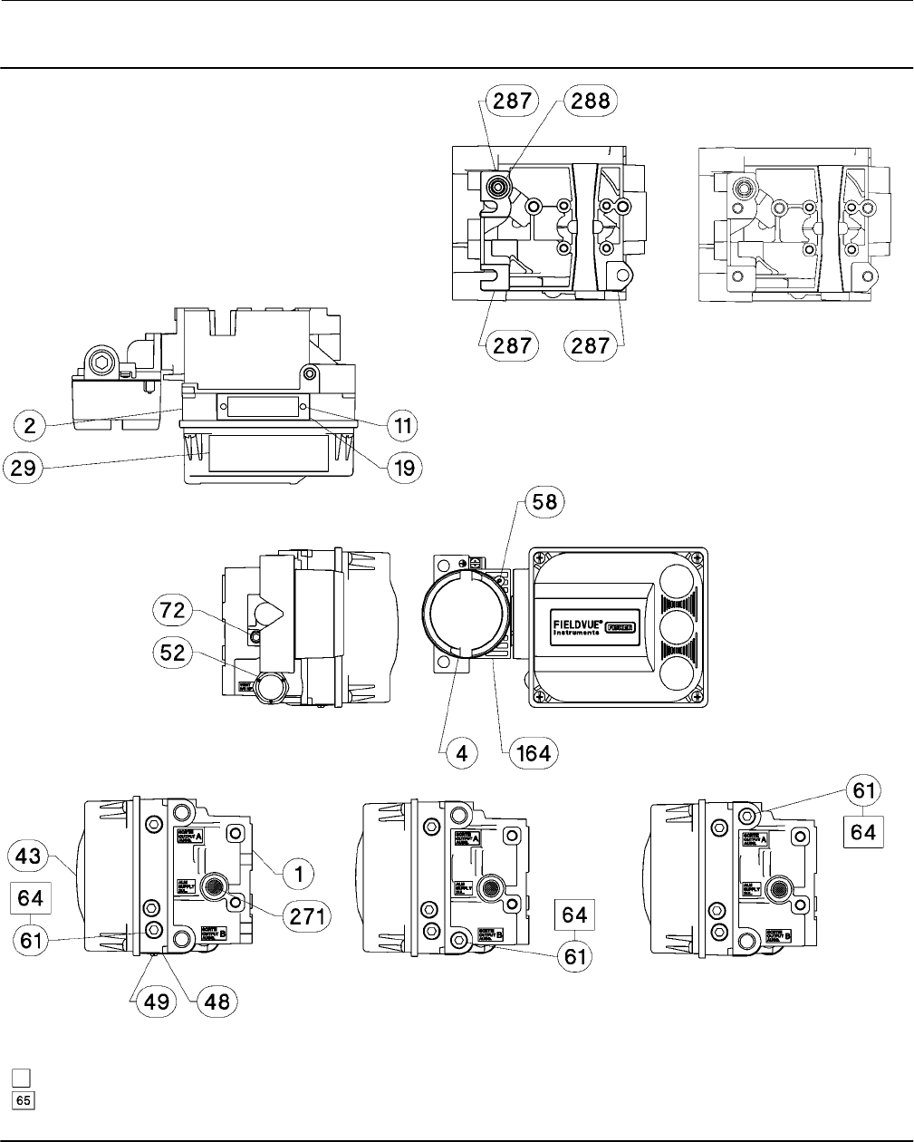
Instruction Manual
D103557X012
Parts
January 2015
77
Figure 7‐2. FIELDVUE DVC6200 SIS Digital Valve Controller
Housing Assembly
DOUBLE‐ACTING DIRECT‐ACTING REVERSE‐ACTING
HOUSING A—BACK VIEW
(USED FOR GX ACTUATOR)
HOUSING B—BACK VIEW
(USED FOR ALL
ACTUATORS EXCEPT GX)
GE40185 sheet 1 of 3
APPLY LUBRICANT, SEALANT, OR THREAD LOCK
APPLY LUBRICANT ON ALL O-RINGS UNLESS OTHERWISE SPECIFIED
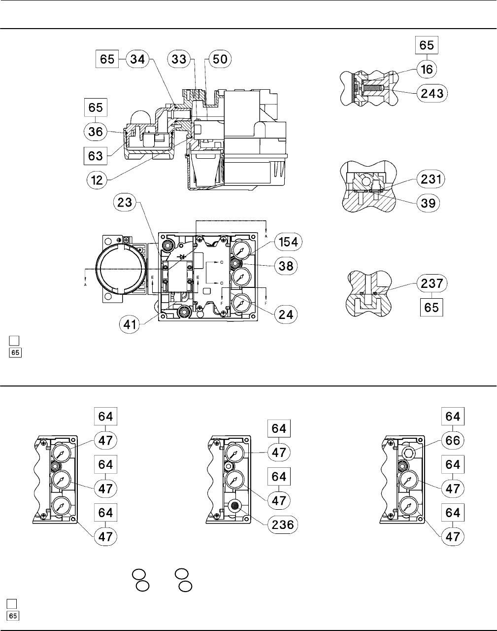
Instruction Manual
D103557X012
Parts
January 2015
78
Figure 7‐2. FIELDVUE DVC6200 SIS Digital Valve Controller Housing Assembly (continued)
SECTION A-A
SECTION C-C
SCALE 2 : 1
SECTION E-E
SCALE 2 : 1
SECTION F-F
SCALE 2 : 1
GE40185 sheet 2 of 3
APPLY LUBRICANT, SEALANT, OR THREAD LOCK
APPLY LUBRICANT ON ALL O-RINGS UNLESS OTHERWISE SPECIFIED
Figure 7‐3. Gauge Configuration
DOUBLE‐ACTING DIRECT‐ACTING REVERSE‐ACTING
GE40185 sheet 3 of 3
APPLY LUBRICANT, SEALANT, OR THREAD LOCK
APPLY LUBRICANT ON ALL O-RINGS UNLESS OTHERWISE SPECIFIED
FOR PIPE PLUG OPTION REPLACE 47 WITH 66
FOR TIRE VALVE OPTION REPLACE 47 WITH 67

Instruction Manual
D103557X012
Parts
January 2015
79
Figure 7‐4. FIELDVUE DVC6205 SIS Base Unit Housing Assembly
SECTION B-B
SECTION H-H
SECTION A-A
GE40181
APPLY LUBRICANT, SEALANT, OR THREAD LOCK
APPLY LUBRICANT ON ALL O-RINGS UNLESS OTHERWISE SPECIFIED
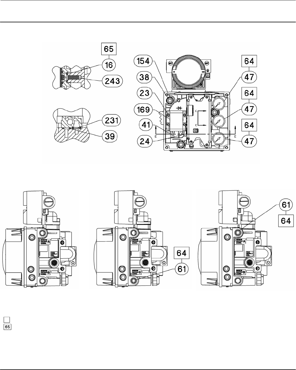
Instruction Manual
D103557X012
Parts
January 2015
80
Figure 7‐4. FIELDVUE DVC6205 SIS Base Unit Housing Assembly (continued)
SECTION C-C
SCALE 2 : 1
SECTION E-E
SCALE 2 : 1
DOUBLE‐ACTING DIRECT‐ACTING REVERSE‐ACTING
DOUBLE‐ACTING SHOWN
GE40181
APPLY LUBRICANT, SEALANT, OR THREAD LOCK
APPLY LUBRICANT ON ALL O-RINGS UNLESS OTHERWISE SPECIFIED
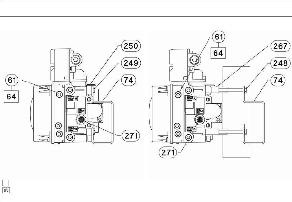
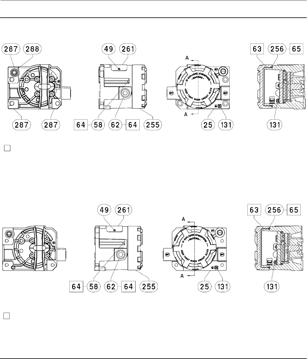
Instruction Manual
D103557X012
Parts
January 2015
82
Figure 7‐5. FIELDVUE DVC6215 Remote Feedback Assembly
SECTION A-A
HOUSING A
(USED FOR GX ACTUATOR)
HOUSING B
(USED FOR ALL ACTUATORS EXCEPT GX)
SECTION A-A
PARTS NOT SHOWN: 158
PARTS NOT SHOWN: 158
GE46670-B
GE40178-B
APPLY LUBRICANT/SEALANT
APPLY LUBRICANT/SEALANT
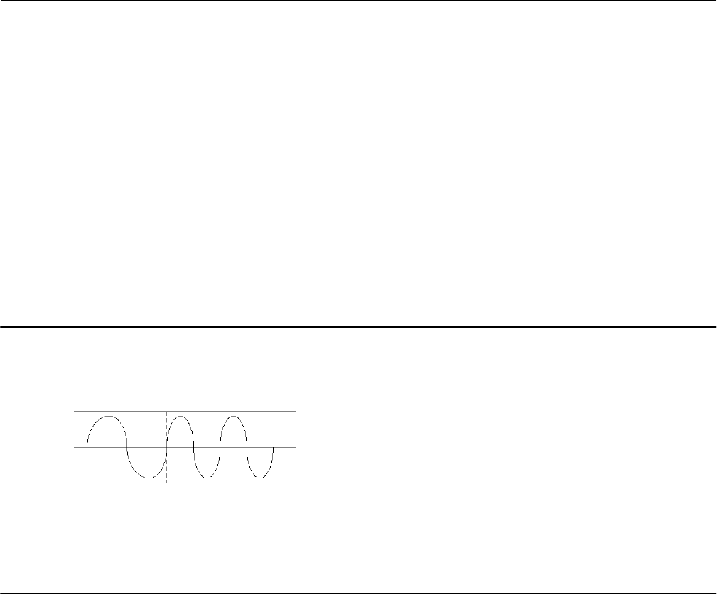
Instruction Manual
D103557X012
Principle of Operation
January 2015
83
Appendix A Principle of OperationAA−A
HART Communication
The HART (Highway Addressable Remote Transducer) protocol gives field devices the capability of communicating
instrument and process data digitally. This digital communication occurs over the same two‐wire loop that provides
the 4‐20 mA process control signal, without disrupting the process signal. In this way, the analog process signal, with
its faster update rate, can be used for control. At the same time, the HART protocol allows access to digital diagnostic,
maintenance, and additional process data. The protocol provides total system integration via a host device.
The HART protocol uses frequency shift keying (FSK). Two individual frequencies of 1200 and 2200 Hz are
superimposed over the 4‐20 mA current signal. These frequencies represent the digits 1 and 0 (see figure A‐1). By
superimposing a frequency signal over the 4-20 mA current, digital communication is attained. The average value of
the HART signal is zero, therefore no DC value is added to the 4‐20 mA signal. Thus, true simultaneous communication
is achieved without interrupting the process signal.
Figure A‐1. HART Frequency Shift Keying Technique
-0.5V
+0.5V
1200 Hz
“1” 2200 Hz
“0”
AVERAGE CURRENT CHANGE DURING COMMUNICATION = 0
ANALOG
SIGNAL
0
A6174
The HART protocol allows the capability of multidropping, i.e., networking several devices to a single communications
line. This process is well suited for monitoring remote applications such as pipelines, custody transfer sites, and tank
farms. See table 6‐2 for instructions on changing the printed wiring board DIP switch configuration to multidrop.
DVC6200 SIS Digital Valve Controller
The DVC6200 SIS digital valve controller housing contains the travel sensor, terminal box, pneumatic input and output
connections and a module base that may be easily replaced in the field without disconnecting field wiring or tubing.
The module base contains the following submodules: I/P converter, printed wiring board (pwb) assembly, and
pneumatic relay. The relay position is detected by sensing the magnet on the relay beam via a detector on the printed
wiring board. This sensor is used for the minor loop feedback (MLFB) reading. The module base can be rebuilt by
replacing the submodules. See figures A‐3 and A‐4.
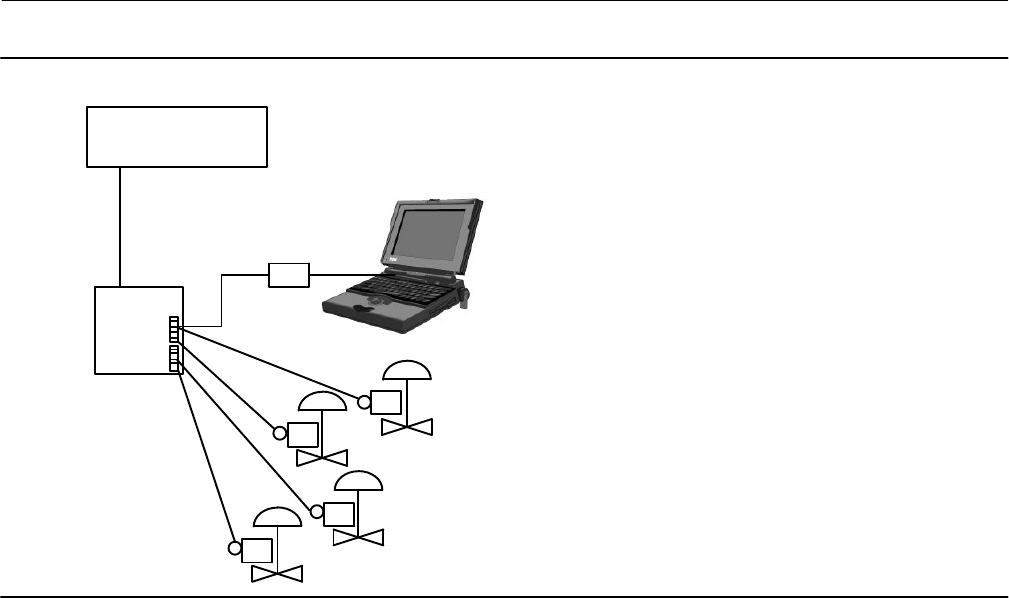
Instruction Manual
D103557X012
Principle of Operation
January 2015
84
Figure A‐2. Typical FIELDVUE Instrument to Personal Computer Connections for ValveLink Software
FIELD TERM.
CONTROL SYSTEM
HART MODEM
E1362
DVC6200 SIS digital valve controllers are loop‐powered instruments that provide a control valve position proportional
to an input signal from the control room. The following describes a double‐acting digital valve controller mounted on a
piston actuator.
The input signal is routed into the terminal box through a single twisted pair of wires and then to the printed wiring
board assembly submodule where it is read by the microprocessor, processed by a digital algorithm, and converted
into an analog I/P drive signal.
As the input signal increases, the drive signal to the I/P converter increases, increasing the I/P output pressure. The I/P
output pressure is routed to the pneumatic relay submodule. The relay is also connected to supply pressure and
amplifies the small pneumatic signal from the I/P converter. The relay accepts the amplified pneumatic signal and
provides two output pressures. With increasing input (4 to 20 mA signal), the output A pressure always increases and
the output B pressure decreases. The output A pressure is used for double‐acting and single‐acting direct applications.
The output B pressure is used for double‐acting and single‐acting reverse applications. As shown in figure A‐3 the
increased output A pressure causes the actuator stem to move downward. Stem position is sensed by the non‐contact
travel feedback sensor. The stem continues to move downward until the correct stem position is attained. At this point
the printed wiring board assembly stabilizes the I/P drive signal. This positions the flapper to prevent any further
increase in nozzle pressure.
As the input signal decreases, the drive signal to the I/P converter submodule decreases, decreasing the I/P output
pressure. The pneumatic relay decreases the output A pressure and increases the output B pressure. The stem moves
upward until the correct position is attained. At this point the printed wiring board assembly stabilizes the I/P drive
signal. This positions the flapper to prevent any further decrease in nozzle pressure.
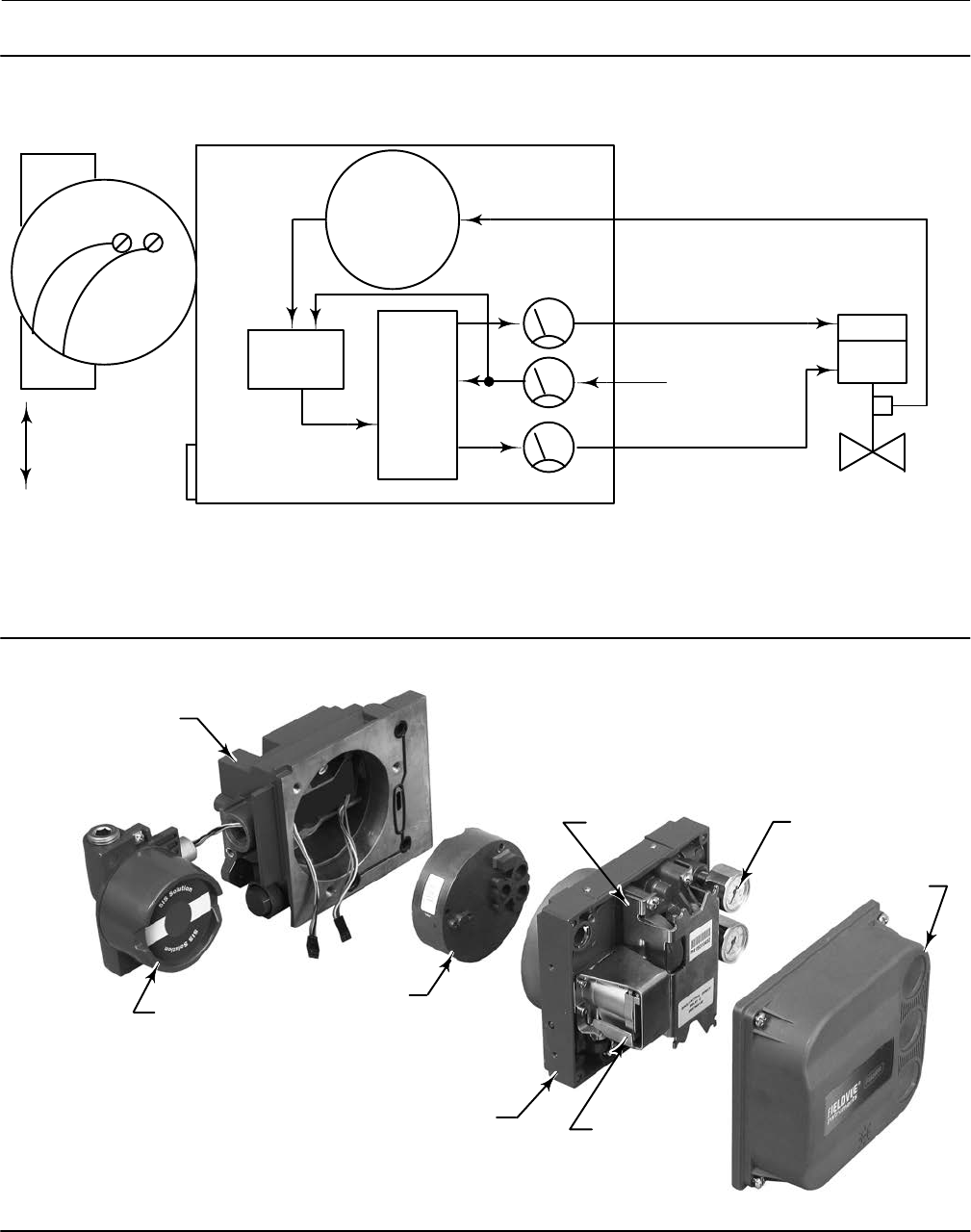
Instruction Manual
D103557X012
Principle of Operation
January 2015
85
Figure A‐3. FIELDVUE DVC6200 SIS Digital Valve Controller Block Diagram
E1470
INPUT SIGNAL
4-20 mA
+
HART
SUPPLY PRESSURE
PRINTED
WIRING BOARD
PNEUMATIC
RELAY
I/P
CONVERTER
OUTPUT A
OUTPUT B
VALVE TRAVEL FEEDBACK
TERMINAL BOX
DRIVE
SIGNAL
VALVE AND ACTUATOR
VENT
TERMINAL BOX
WITH COVER
MODULE BASE ASSEMBLY
PRINTED WIRING
BOARD ASSEMBLY
I/P CONVERTER
PNEUMATIC
RELAY
HOUSING
GAUGES
COVER
W9925-2-SIS
Figure A‐4. FIELDVUE DVC6200 SIS Digital Valve Controller Assembly

Instruction Manual
D103557X012
Principle of Operation
January 2015
86

Instruction Manual
D103557X012
Field Communicator Menu Trees
January 2015
87
Appendix B Field Communicator Menu Trees
This section contains the DVC6200 SIS Field Communicator menu trees. It also contains an alphabetized
function/variable list to help locate the function/variable on the appropriate menu tree. All Fast Key Sequences
referenced in the menu trees assume the Online menu (see figure B-2) as the starting point.
Function/Variable List
Function/Variable See Figure
Action on Failed Test B-7
Actual Travel B-5
Actuator Manufacturer B-5
Actuator Model B-5
Actuator Selection B-5
Actuator Size B-5
Actuator Style B-7
Air B-5
Alert Record Full Enable B-8
Alert Record Not Empty Enable B-8
Alert Switch Source B-7
Analog Input B-3, B-10
Analog Input (Calibration) B-9
Analog Input Units B-5
Area Units B-5
Auto Calibration B-9
Auto Test Interval B-7
Auxiliary Terminal Action B-5
Auxiliary Terminal Action, Edit B-5
Breakout Torque B-5
Burst Mode B-7
Calibration Button B-5
Calibration Record B-9
Calibration Time B-9
Calibration Type B-9
Calibrator B-9
Change Device Powerup B-7
Change Instrument Mode B-1, B-5
Change to HART 5 B-10
Change to HART 7 B-10
Change Write Protection B-1, B-3, B-5
Clear Records B-8, B-10
Critical NVM Failure Shutdown B-8
Custom Characterization B-6, B-10
Cycle Count Alert Enable B-8
Cycle Count Alert Point B-8
Cycle Counter B-10
Cycle Count/Travel Accum Deadband B-8
Days Powered Up B-10
DD Information B-3
Description B-3, B-5
Device ID B-3
Device Revision B-3
Device Setup B-4
Device Status B-3, B-10
Function/Variable See Figure
Drive Current Failure Shutdown B-8
Drive Signal B-10
Drive Signal Alert Enable B-8
Dynamic Torque B-5
Edit Cycle Counts B-8
Edit Instrument Time B-5, B-8
Edit Travel Accumulator B-8
Effective Area (Acutator) B-5
End Point Pressure Control (EPPC) B-6
EPPC Deviation (Alert Setup) B-8
Fail Signal B-7
Feedback Connection B-7
Firmware Revision B-3
Flash Integrity Failure Shutdown B-8
Flow Direction B-5
Flow Tends to B-5
Function B-7
Hardware Revision (Device) B-3
HART Long Tag B-3, B-5
HART Tag B-3, B-5
HART Universal Revision B-3
Hi Cutoff Point B-6, B-8
HART Variable Assignments B-7
Inlet Pressure B-5
Input Characterization B-6, B-10
Instrument Alert Record B-8
Instrument Level B-3
Instrument Mode B-1, B-5
Instrument Serial Number B-3, B-5
Instrument Time is Approximate Enable B-8
Integral Enable B-6
Integral Gain B-6
Integrator Saturated High Enable B-8
Integrator Saturated Lo Enable B-8
Integrator Limit B-6
Intgegral Dead Zone B-6
Last AutoCal Status B-9
LCP Communication Failure Enable B-8
Leak Class (Trim) B-5
Length Units B-5
Lever Arm Length B-5
Lever Style B-5
Limit Switch Trip Point B-7
Limit Switch Valve Close B-5
Limit Switch Valve Open B-5

Instruction Manual
D103557X012
Field Communicator Menu Trees
January 2015
88
Function/Variable See Figure
Lo Cutoff Point B-6, B-8
Loop Current Validation Shutdown B-8
Loop Initiated PST B-7
Manual Calibration B-9
Manufacturer (Device) B-3
Maximum Recorded Temperature B-10
Maximum Supply Pressure B-7
Message B-3, B-5
Mininum Recorded Temperature B-10
Minor Loop Sensor Failure Shutdown B-8
MLFB Gain B-6
Model (Device) B-3
Non-Critical NVM Failure Shutdown B-8
Number of Power Ups B-10
Outlet Pressure B-5
Output Circuit Comm Failure Enable B-8
Output Terminal Enable B-7
Packing Type B-5
Partial Stroke Test B-10
Partial Stroke Test (PST) B-7
Performance Tuner B-4, B-6, B-10
Polling Address B-5
Port Diameter (Trim) B-5
Port Type (Trim) B-5
Position Transmitter B-5
Pressure A B-3, B-10
Pressure A-B B-3, B-10
Pressure B B-3, B-10
Pressure Sensor Failure Shutdown B-8
Pressure Sensors (Calibration) B-9
Pressure Units B-5
Program Flow Faiilure Shutdown B-8
Proportional Gain B-6
PST Enable B-7
PST Calibration B-9
PST Pressure Limit B-7
PST Start Point B-7
PST Variables B-7
Push Down To (Trim) B-5
PWB Serial Number B-3
Rated Travel B-5
Relay Adjust B-9
Relay Type B-7
Reference Voltage Failure Shutdown B-8
Reset Valve Stuck Alert B-10
Restart Processor B-10
Seat Type (Trim) B-5
Setpoint B-3, B-10
Shutdown on Alert B-8
SIS Hardware Failure Shutdown B-8
SIS Locked in Safety Alert Enable B-8
Solenoid Valve B-5
Function/Variable See Figure
SP Rate Close B-6
SP Rate Open B-6
Spring Rate B-5
Spring Rate Units B-5
Stabilize/Optimize B-6, B-10
Stem Diameter B-5
Stroke Valve B-10
Supply Pressure B-3, B-10
Supply Pressure Lo Alert B-8
Switch Closed B-7
Temperature B-10
Temperature Units B-5
Temp Sensor Failure Shutdown B-8
Torque Units B-5
Transmitter Output B-7
Travel B-3
Travel Accumulator B-10
Travel Accumulator Alert Enable B-8
Travel Accumulator Alert Point B-8
Travel Alert Deadband B-8
Travel Alert Hi Enable B-8
Travel Alert Hi Hi Enable B-8
Travel Alert Hi Hi Point B-8
Travel Alert Hi Point B-8
Travel Alert Lo Enable B-8
Travel Alert Lo Lo Enable B-8
Travel Alert Lo Lo Point B-8
Travel Alert Lo Point B-8
Travel Counts B-10
Travel Deviation (Alert Setup) B-8
Travel Cutoff High Enable B-8
Travel Cutoff Lo Enable B-8
Travel Sensor Failure Shutdown B-8
Travel Sensor Motion B-7
Travel Tuning Set B-6
Travel Units B-5
Tripped by the LCP Enable B-8
Unbalanced Area (Trim) B-5
Valve Class B-5
Valve Manufacturer B-5
Valve Model B-5
Valve Serial Number B-3, B-5
Valve Size B-5
Valve Style B-7
Velocity Gain B-6
View Alert Records B-10
View Edit Lag Time B-6
Volume Booster B-5
Write Protection B-1, B-3, B-5
Zero Power Condition B-7

Instruction Manual
D103557X012
Field Communicator Menu Trees
January 2015
89
Figure B-1. Hot Key
Hot Key
1 Instrument Mode
2 Change Instrument Mode
3 Write Protection
4 Change Write Protection
Figure B-2. Online
Online
1 Overview
2 Configure
3 Service Tools
HART Application
1 Offline
2 Online
3 Utility
4 HART Diagnostics
Figure B-3. Overview (1)
Device Information
1 Identification
2 Revisions
3 Security
Identification
1 HART Tag
2 HART Long Tag
3 Manufacturer
4 Model
5 Instrument Level
6 Device ID and Serial Numbers
7 Message
8 Description
Overview
1 Device Status
2 Analog Input
3 Setpoint
4 Travel
5 Supply Pressure
6 Pressure A
7 Pressure B
8 Pressure A-B
9 Device Information
Revisions
1 HART Universal Revision
2 Device Revision
3 Hardware Revision
4 Firmware Revision
5 DD Information
Security
1 Write Protection
2 Change Write Protection
1-9
1-9-1
1-9-2
1 HART LONG TAG IS AVAILABLE WITH HART 7.
NOTE:
Device ID and Serial Numbers
1 Device ID
2 Valve Serial Number
3 Instrument Serial Number
4 PWB Serial Number
1-9-3
1-9-1-5 (HART 5)
1-9-1-6 (HART 7)
1
Figure B-4. Guided Setup (2-1)
Guided Setup
1 Device Setup
2 Performance Tuner
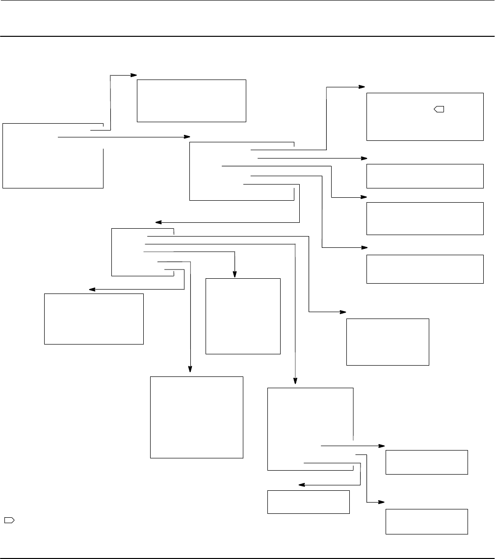
Instruction Manual
D103557X012
Field Communicator Menu Trees
January 2015
90
Figure B-5. Manual Setup > Mode Protection (2-2-1) and Manual Setup > Instrument (2-2-2)
Manual Setup
1 Mode and Protection
2 Instrument
3 Travel/Pressure Control
4 Tuning
5 Valve and Actuator
6 SIS / Partial Stroke
7 Outputs
Mode and Protection
1 Instrument Mode
2 Change Instrument Mode
3 Write Protection
4 Change Write Protection
Instrument
1 Identification
2 Serial Numbers
3 Units
4 Terminal Box
5 Spec Sheet
6 Edit Instrument Time
Identification
1 HART Tag
2 HART Long Tag
3 Description
4 Message
5 Polling Address
Serial Numbers
1 Instrument Serial Number
2 Valve Serial Number
Units
1 Pressure Units
2 Temperature Units
3 Analog Input Units
Terminal Box
1 Calibration Button
2 Auxiliary Terminal Action
3 Edit Auxiliary Terminal Action
Spec Sheet
1 Units
2 Valve
3 Trim
4 Actuator
5 Accessories
2-2-1
2-2-2-1
2-2-2-2
2-2-2-3
2-2-2-4
2-2-2-5
1
NOTE:
1 HART LONG TAG IS AVAILABLE WITH HART 7.
Units
1 Travel Units
2 Length Units
3 Area Units
4 Spring Rate Units
5 Torque Units
Trim
1 Seat Type
2 Leak Class
3 Port Diameter
4 Port Type
5 Flow Direction
6 Push Down To
7 Flow Tends To
8 Unbalanced Area
Valve Travel
1 Rated Travel
2 Actual Travel
Inlet/Outlet Pressures
1 Inlet Pressure
2 Outlet Pressure
Torque
1 Dynamic Torque
2 Breakout Torque
Valve
1 Valve Manufacturer
2 Valve Model
3 Valve Size
4 Valve Class
5 Stem Diameter
6 Packing Type
7 Valve Travel
8 Inlet/Outlet Pressures
9 Torque
Actuator
1 Actuator Manufacturer
2 Actuator Model
3 Actuator Size
4 Actuator Selection
5 Lever Style
6 Lever Arm Length
7 Effective Area
8 Spring Rate
9 Air
Accessories
1 Volume Booster
2 Solenoid Valve
3 Position Transmitter
4 Limit Switch Valve Open
5 Limit Switch Valve Close
2-2-2-5-1
2-2-2-5-3
2-2-2-5-4
2-2-2-5-5
2-2-2-5-2
2-2-2-5-2-7
2-2-2
2-2-2-5-2-9
2-2-2-5-2-8
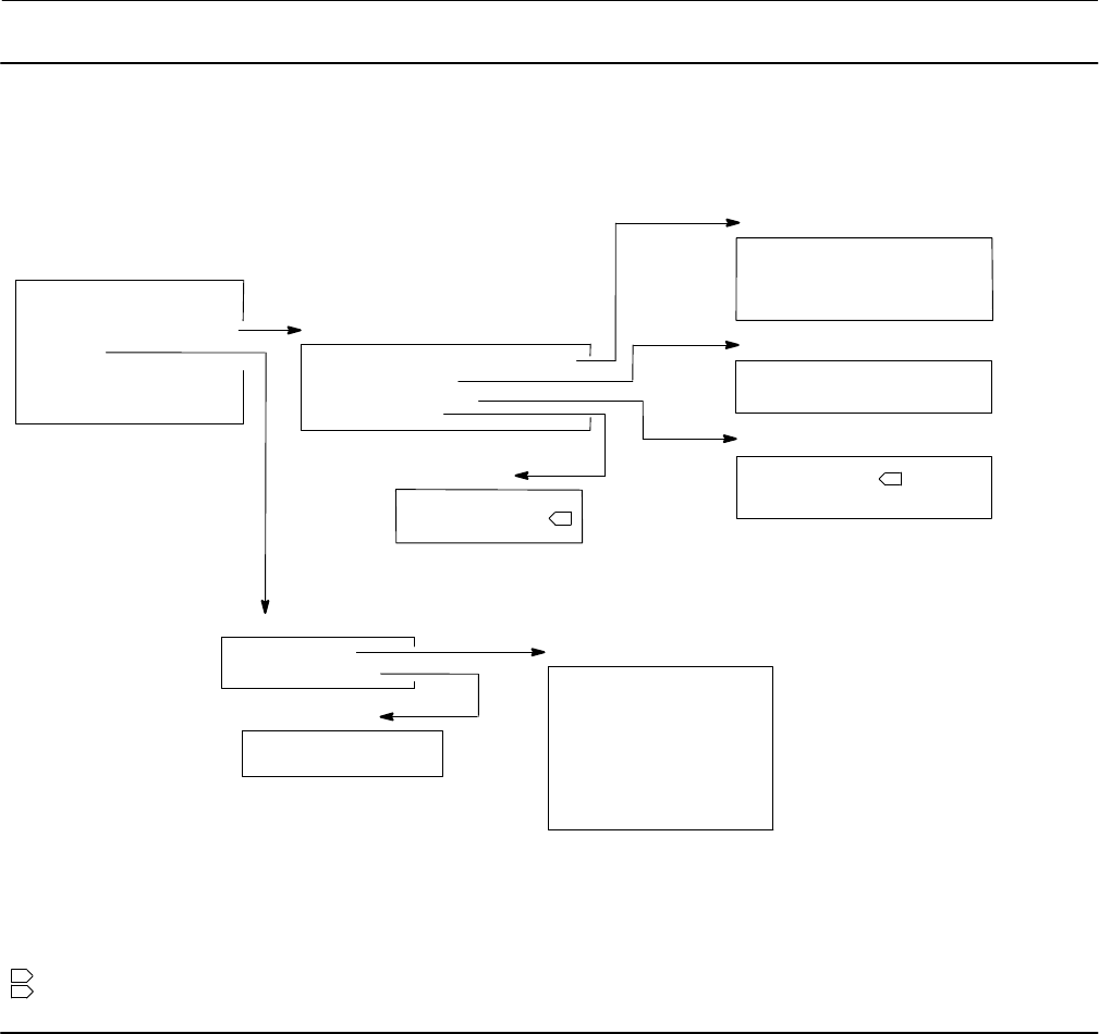
Instruction Manual
D103557X012
Field Communicator Menu Trees
January 2015
91
Figure B-6. Manual Setup > Travel/Pressure Control (2-2-3) and Manual Setup > Tuning (2-2-4)
Manual Setup
1 Mode and Protection
2 Instrument
3 Travel/Pressure Control
4 Tuning
5 Valve and Actuator
6 Partial Stroke Test (PST)
7 Outputs
Travel/Pressure Control
1 End Point Pressure Control (EPPC)
2 Characterization
3 Dynamic Response
4 Travel Cutoffs
Travel Cutoffs
1 Hi Cutoff Point
3 Lo Cutoff Point
Dynamic Response
1 SP Rate Open
2 SP Rate Close
3 View/Edit Lag Time
Characterization
1 Input Characterization
2 Custom Characterization
End Point Pressure Control (EPPC)
1 EPPC Enab
2 Change EPPC Enab
3 EPPC Set Point
4 EPPC Saturation Time
2-2-3
2-2-3-1
2-2-3-2
2-2-3-3
2-2-3-4
NOTES:
1 SP RATE OPEN AND SP RATE CLOSE ARE NOT VISIBLE WHEN SHUTDOWN SWITCHS ARE ENABLED.
2 HI CUTOFF POINT AND LOW CUTOFF POINT ARE NOT VISIBLE WHEN SHUTDOWN SWITCHS ARE ENABLED.
1
2
Integral Settings
1 Integral Dead Zone
2 Integrator Limit
Tuning
1 Travel Tuning
2 Integral Settings
Travel Tuning
1 Travel Tuning Set
2 Proportional Gain
3 Velocity Gain
4 MLFB Gain
5 Integral Enable
6 Integral Gain
7 Performance Tuner
8 Stabilize/Optimize
2-2-4
2-2-4-2
2-2-4-1
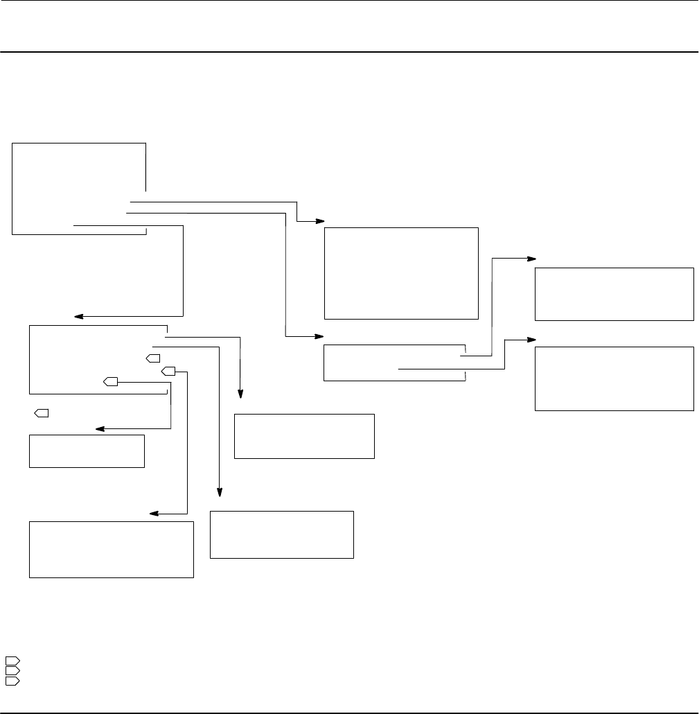
Instruction Manual
D103557X012
Field Communicator Menu Trees
January 2015
92
Figure B-7. Manual Setup > Valve and Actuator (2-2-5) through Manual Setup > Outputs (2-2-7)
Manual Setup
1 Mode and Protection
2 Instrument
3 Travel/Pressure Control
4 Tuning
5 Valve and Actuator
6 SIS / Partial Stroke
7 Outputs
Outputs
1 Output Terminal Config
2 Switch Configuration
3 Transmitter Output
4 HART Var Assignments
5 Burst Mode
HART Var Assignments
1 Primary Variable (PV)
2 Secondary Variable (SV)
3 Tertiary Variable (TV)
4 Quaternary Variable (QV)
Output Terminal Config
1 Output Terminal Enable
2 Function
3 Fail Signal
Valve and Actuator
1 Valve Style
2 Actuator Style
3 Feedback Connection
4 Relay Type
5 Zero Power Condition
6 Travel Sensor Motion
7 Maximum Supply Pressure
2-2-5
Switch Configuration
1 Limit Switch Trip Point
2 Alert Switch Source
3 Switch Closed
3
1 THIS MENU ITEM IS HART VAR ASSIGNMENTS WITH HART 5.
2 THIS MENU ITEM IS TRANSMITTER OUTPUT WITH HART 5.
NOTES:
2-2-7
SIS / Partial Stroke
1 Partial Stroke Test (PST)
2 SIS Options
2-2-6
Burst Mode
1 Burst Enable
2 Burst Command
2-2-7-2
2-2-7-1
2-2-7-5
2-2-7-4
3
3 BURST MODE IS AVAILABLE WITH HART 5.
1
2
Partial Stroke Test (PST)
1 PST Pressure Limit
2 PST Enable
3 PST Start Point
4 PST Variables
SIS Options
1 Auto Test Interval
2 Loop-Initiated PST
3 Change Device Power Up
4 Action on Failed Test
2-2-6-1
2-2-6-2
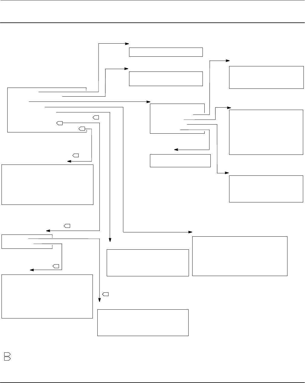
Instruction Manual
D103557X012
Field Communicator Menu Trees
January 2015
93
Figure B-8. Alert Setup (2-3)
Electronics
1 Drive Signal Alert Enable
2-3-1
Alert Setup
1 Electronics
2 Supply Pressure Alert
3 Travel
4 Travel History
5 SIS / Partial Stroke
6 Output Circuit Comm Failure Enable
7 Shutdown On Alert
8 Alert Record/Instrument Time
Sensors
1 Travel Sensor Failure Shutdown
2 Temp Sensor Failure Shutdown
3 Minor Loop Sensor Failure Shutdown
4 Pressure Sensor Failure Shutdown
Travel
1 Travel Alert DB
2 Travel Deviation
3 Travel Limit
4 Travel Cutoff
5 Integrator
Travel Deviation
1 Travel Deviation
2 Travel Deviation Alert Enable
3 Travel Deviation Alert Point
4 Travel Deviation Time
Travel Limit
1 Travel Alert Hi Hi Enable
2 Travel Alert Hi Hi Point
3 Travel Alert Lo Lo Enable
4 Travel Alert Lo Lo Point
5 Travel Alert Hi Enable
6 Travel Alert Hi Point
7 Travel Alert Lo Enable
8 Travel Alert Lo Point
Travel Cutoff
1 Travel Cutoff Hi Enable
2 Hi Cutoff Point
3 Travel Cutoff Lo Enable
4 Lo Cutoff Point
Integrator
1 Integrator Sat Hi Enable
2 Integrator Sat Lo Enable
Travel History
1 Cycle Count/Travel Accum Deadband
2 Cycle Count Alert Enable
3 Edit Cycle Counts
4 Cycle Count Alert Point
5 Travel Accumulator Alert Enable
6 Edit Travel Accumulator
7 Travel Accumulator Alert Point
Alert Record/Instrument Time
1 Alert Record Not Empty Enable
2 Alert Record Full Enable
3 View Alert Records
4 Clear Records
5 Instrument Alert Record
6 Instrument Time is Approximate Enable
7 Edit Instrument Time
1
2-3-4
Supply Pressure Lo Alert
1 Supply Pressure Lo Alert Enable
2 Supply Pressure Lo Alert Point
NOTES:
1 OUTPUT CIRCUIT COMM FAILURE ENABLE IS AVAILABLE WHEN THE TRANSMITTER FUNCTION IS CONFIGURED.
2-3-2
2-3-3
2-3-3-2
2-3-3-3
2-3-3-5
2-3-3-4
SIS / Partial Stroke
1 EPPC Deviation
2 Tripped by the LCP Enable
3 SIS Locked in Safety Alert Enable
4 LCP Communication Failure Enable
2-3-5
Electronics
1 Drive Current Failure Shutdown
2 Critical NVM Failure Shutdown
3 Non-Critical NVM Failure Shutdown
4 Flash Integrity Failure Shutdown
5 Reference Voltage Failure Shutdown
6 Program Flow Failure Shutdown
7 SIS Hardware Failure Shutdown
8 Loop Current Validation Shutdown
2-3-8
Shutdown On Alert
1 Sensors
2 Electronics
2-3-7
2-3-7-1
2-3-7-2
2
2
2
2
2
2
2 FAST KEY SEQUENCES FOR THESE MENUS DROP ONE MENU SEQUENCE WHEN THE TRANSMITTER FUNCTION IS NOT CONFIGURED.
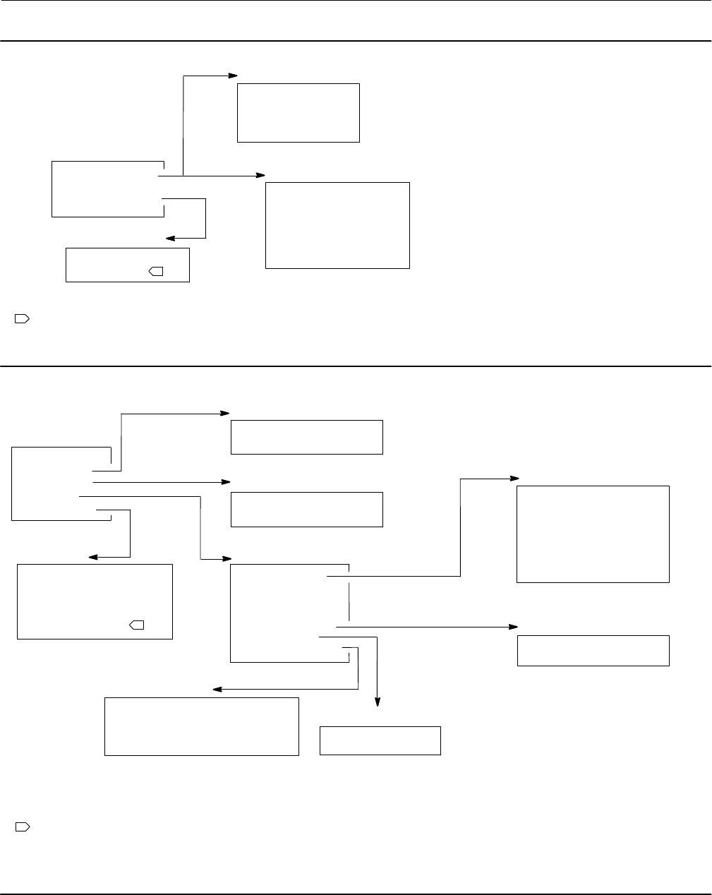
Instruction Manual
D103557X012
Field Communicator Menu Trees
January 2015
94
Figure B-9. Calibration (2-4)
Calibration
1 Travel Calibration
2 Relay Adjust
3 Sensor Calibration
4 PST Calibration
Travel Calibration
1 Auto Calibration
2 Last AutoCal Status
3 Manual Calibration
4 Calibration Record
Sensor Calibration
1 Pressures Sensors
2 Analog Input
2-4-1
2-4-3
HART 5
HART 5
HART 7 Travel Calibration
1 Auto Calibration
2 Last AutoCal Status
3 Manual Calibration
4 Calibration Type
5 Calibration Time
6 Calibrator
2-4-1
HART 7
NOTE:
1
1 ANALOG INPUT IS NOT AVAILABLE WHEN THE DIP SWITCH IS SET TO MULTI-DROP.
Figure B-10. Service Tools (3)
Service Tools
1 Device Status
2 Alert Record
3 Diagnostics
4 Variables
5 Maintenance
Diagnostics
1 Stroke Valve
2 Partial Stroke Test
3-4
Variables
1 Travel/Pressure
2 Analog Input
3 Temperature
4 Travel Counts
5 Characterization
6 Travel History
7 Run Time Extremes
3-3 Travel/Pressure
1 Setpoint
2 Travel
3 Drive Signal
4 Supply Pressure
5 Pressure A
6 Pressure B
7 Pressure A-B
Characterization
1 Input Characterization
2 Custom Characterization
Travel History
1 Cycle Counter
2 Travel Accumulator
Run Time Extremes
1 Maximum Recorded Temperature
2 Minimum Recorded Temperature
3 Days Powered Up
4 Number of Power Ups
Maintenance
1 Performance Tuner
2 Stabilize/Optimize
3 Restart Processor
4 Reset Valve Stuck Alert
5 Change to HART 5
3-4-7
3-4-6
3-5
1 THIS MENU ITEM READS CHANGE TO HART 7 WITH HART 5.
Alert Record
1 View Alert Records
2 Clear Records
3-2
1
3-4-1
3-4-5
NOTE:

Instruction Manual
D103557X012
Glossary
January 2015
95
Glossary
Alert Point
An adjustable value that, when exceeded,
activates an alert.
Algorithm
A set of logical steps to solve a problem or
accomplish a task. A computer program contains
one or more algorithms.
Alphanumeric
Consisting of letters and numbers.
Analog Input Units
Units in which the analog input is displayed and
maintained in the instrument.
ANSI (acronym)
The acronym ANSI stands for the American
National Standards Institute
ANSI Class
Valve pressure/temperature rating.
Bench Set
Pressure, supplied to an actuator, required to
drive the actuator through rated valve travel.
Expressed in pounds per square inch.
Byte
A unit of binary digits (bits). A byte consists of
eight bits.
Calibration Location
Where the instrument was last calibrated; either
in the factory or in the field.
Configuration
Stored instructions and operating parameters for
a FIELDVUE Instrument.
Control Loop
An arrangement of physical and electronic
components for process control. The electronic
components of the loop continuously measure
one or more aspects of the process, then alter
those aspects as necessary to achieve a desired
process condition. A simple control loop
measures only one variable. More sophisticated
control loops measure many variables and
maintain specified relationships among those
variables.
Control Mode
Defines where the instrument reads its set point.
The following control modes are available for a
FIELDVUE Instrument:
Analog The instrument receives its travel set
point over the 4‐20 mA loop.
Digital The instrument receives its set point
digitally, via the HART communications link.
Test This is not a user‐selectable mode. The Field
Communicator or ValveLink software places the
instrument in this mode whenever it needs to
move the valve, such as for calibration or
diagnostic tests.
Control Mode, Restart
Determines the instrument control mode after a
restart. See Control Mode for the available restart
control modes.
Controller
A device that operates automatically to regulate a
controlled variable.
Current‐to‐Pressure (I/P) Converter
An electronic component or device that converts
a milliamp signal to a proportional pneumatic
pressure output signal.
Cycle Counter
The capability of a FIELDVUE instrument to record
the number of times the travel changes direction.
The change in direction must occur after the
deadband has been exceeded before it can be
counted as a cycle.

Instruction Manual
D103557X012
Glossary
January 2015
96
Cycle Counter Alert
Checks the difference between the Cycle Counter
and the Cycle Counter Alert Point. Cycle Counter
Alert is active when the cycle counter value
exceeds the Cycle Counter Alert Point. It clears
after you reset the Cycle Counter to a value less
than the alert point.
Cycle Counter Alert Point
An adjustable value which, when exceeded,
activates the Cycle Counter Alert. Valid entries
are 0 to 4 billion cycles.
Cycle Counter Deadband
Region around the travel reference point, in
percent of ranged travel, established at the last
increment of the Cycle Counter. The deadband
must be exceeded before a change in travel can
be counted as a cycle. Valid entries are 0% to
100%. Typical value is between 2% and 5%.
Deviation
Usually, the difference between set point and
process variable. More generally, any departure
from a desired or expected value or pattern.
Device ID
Unique identifier embedded in the instrument at
the factory.
Device Revision
Revision number of the interface software that
permits communication between the Field
Communicator and the instrument.
Drive Signal
The signal to the I/P converter from the printed
wiring board. It is the percentage of the total
microprocessor effort needed to drive the valve
fully open.
Drive Signal Alert
Checks the drive signal and calibrated travel. If
one of the following conditions exists for more
than 20 seconds, the Drive Signal Alert is active. If
none of the conditions exist, the alert is cleared.
If Zero Power Condition = Closed
The alert is active when:
drive signal <10% and calibrated travel >3%
drive signal >90% and calibrated travel <97%
If Zero Power Condition = Open
The alert is active when:
drive signal <10% and calibrated travel <97%
drive signal >90% and calibrated travel >3%
Equal Percentage
A valve flow characteristic where equal
increments of valve stem travel produce equal
percentage changes in existing flow. One of the
input characteristics available for a FIELDVUE
Instrument. See also, Linear and Quick Opening.
Feedback Signal
Indicates to the instrument the actual position of
the valve. The travel sensor provides the feedback
signal to the instrument printed wiring board
assembly.
Firmware Revision
The revision number of the instrument firmware.
Firmware is a program that is entered into the
instrument at time of manufacture and cannot be
changed by the user.
Free Time
Percent of time that the microprocessor is idle. A
typical value is 25%. The actual value depends on
the number of functions in the instrument that
are enabled and on the amount of
communication currently in progress.
Full Ranged Travel
Current, in mA, that corresponds with the point
where ranged travel is maximum, i.e., limited by
the mechanical travel stops.
Gain
The ratio of output change to input change.
Hardware Revision
Revision number of the Fisher instrument
hardware. The physical components of the
instrument are defined as the hardware.

Instruction Manual
D103557X012
Glossary
January 2015
97
HART (acronym)
The acronym HART stands for Highway
Addressable Remote Transducer.
HART Universal Revision
Revision number of the HART Universal
Commands which are the communications
protocol for the instrument.
Input Characteristic
The relationship between the ranged travel and
ranged input. Possible values include: linear,
equal percentage, and quick opening.
Input Current
The current signal from the control system that
serves as the analog input to the instrument. See
also Input Signal.
Input Range
The analog input signal range that corresponds to
the travel range.
Input Signal
The current signal from the control system. The
input signal can be displayed in milliamperes or in
percent of ranged input.
Instrument Level
Determines the functions available for the
instrument.
Instrument Mode
Determines if the instrument responds to its
analog input signal. There are two instrument
modes:
In Service: For a fully functioning instrument, the
instrument output changes in response to analog
input changes. Typically changes to setup or
calibration cannot be made when the instrument
mode is In Service.
Out of Service: The instrument output does not
change in response to analog input changes
when the instrument mode is Out of Service.
Some setup parameters can be changed only
when the instrument mode is Out of Service.
Instrument Protection
Determines if commands from a HART device can
calibrate and/or configure certain parameters in
the instrument. There are two types of
instrument protection:
Configuration and Calibration: Prohibits changing
protected setup parameters; prohibits
calibration.
None: Permits both configuration and calibration.
The instrument is ”unprotected.”
Instrument Serial Number
The serial number assigned to the printed wiring
board by the factory but can be changed during
setup. The instrument serial number should
match the serial number on the instrument
nameplate.
Leak Class
Defines the allowable leakage by a valve when it is
closed. Leak class numbers are listed in two
standards: ANSI/FCI 70‐2 and IEC 534‐4.
Linear
A valve flow characteristic where changes in flow
rate are directly proportional to changes in valve
stem travel. One of the input characteristics
available for a FIELDVUE Instrument. See also,
Equal Percentage and Quick Opening.
Linearity, dynamic
Linearity (independent) is the maximum
deviation from a straight line best fit to the
opening and closing curves and a line
representing the average value of those curves.
Memory
A type of semiconductor used for storing
programs or data. FIELDVUE instruments use
three types of memory: Random Access Memory
(RAM), Read Only Memory (ROM), and
Non‐Volatile Memory (NVM). See also these
listings in this glossary.
Menu
A list of programs, commands, or other activities
that you select by using the arrow keys to
highlight the item then pressing ENTER, or by
entering the numeric value of the menu item.

Instruction Manual
D103557X012
Glossary
January 2015
98
Minimum Closing Time
Minimum time, in seconds, for the travel to
decrease through the entire ranged travel. This
rate is applied to any travel decrease. Valid entries
are 0 to 400 seconds. Deactivate by entering a
value of 0 seconds.
Minimum Opening Time
Minimum time, in seconds, for the travel to
increase through the entire ranged travel. This
rate is applied to any travel increase. Because of
friction, actual valve travel may not respond in
exactly the same time frame. Valid entries are 0
to 400 seconds. Deactivate by entering a value of
0 seconds.
Non‐Volatile Memory (NVM)
A type of semiconductor memory that retains its
contents even though power is disconnected.
NVM contents can be changed during
configuration unlike ROM which can be changed
only at time of instrument manufacture. NVM
stores configuration restart data.
Parallel
Simultaneous: said of data transmission on two or
more channels at the same time.
Polling Address
Address of the instrument. If the digital valve
controller is used in a point‐to‐point
configuration, set the polling address to 0. If it is
used in a multidrop configuration, or split range
application, set the polling address to a value
from 0 to 15.
Pressure Sensor
A FIELDVUE instrument internal device that
senses pneumatic pressure. The DVC6200 SIS has
three pressure sensors: one to sense supply
pressure and two to sense the output pressures.
Primary Master
Masters are communicating devices. A primary
master is a communicating device permanently
wired to a field instrument. Typically, a
HART‐compatible control system or a computer
running ValveLink software is the primary master.
In contrast, a secondary master is not often
permanently wired to a field instrument. The
Field Communicator or a computer running
ValveLink software communicating through a
HART modem could be considered a secondary
master.
Note: If one type of master takes an instrument
Out Of Service, the same type must put it In
Service. For example, if a device set up as a
primary master takes an instrument Out Of
Service, a device set up as a primary master must
be used to place the instrument In Service.
Quick Opening
A valve flow characteristic where most of the
change in flow rate takes place for small amounts
of stem travel from the closed position. The flow
characteristic curve is basically linear through the
first 40 percent of stem travel. One of the input
characteristics available for a FIELDVUE
Instrument. See also, Equal Percentage and
Linear.
Random Access Memory (RAM)
A type of semiconductor memory that is normally
used by the microprocessor during normal
operation that permits rapid retrieval and storage
of programs and data. See also Read Only
Memory (ROM) and Non‐Volatile Memory (NVM).
Rate
Amount of change in output proportional to the
rate of change in input.
Read‐Only Memory (ROM)
A memory in which information is stored at the
time of instrument manufacture. You can
examine but not change ROM contents.
Seat Load
Force exerted on the valve seat, typically
expressed in pounds force per lineal inch of port
circumference. Seat load is determined by shutoff
requirements.
Set Point Filter Time (Lag Time)
The time constant, in seconds, for the first‐order
input filter. The default of 0 seconds will bypass
the filter.

Instruction Manual
D103557X012
Glossary
January 2015
99
Software
Microprocessor or computer programs and
routines that reside in alterable memory (usually
RAM), as opposed to firmware, which consists of
programs and routines that are programmed into
memory (usually ROM) when the instrument is
manufactured. Software can be manipulated
during normal operation, firmware cannot.
Stroke Time
The DVC6200 SIS calculates the time it takes to
fully stroke in the event of a demand and stores
the last value. In order for the calculation to
occur, the Travel Hi Hi and Travel Lo Lo alert
points must be configured to 99% and 1%
respectively. Stroke time can be read from the
device with ValveLink software.
Stroking Time
The time, in seconds, required to move the valve
from its fully open position to fully closed, or vice
versa.
Temperature Sensor
A device within the FIELDVUE instrument that
measures the instrument's internal temperature.
Travel
Movement of the valve stem or shaft which
changes the amount the valve is open or closed.
Travel Accumulator
The capability of a FIELDVUE instrument to record
total change in travel. The value of the Travel
Accumulator increments when the magnitude of
the change exceeds the Travel Accumulator
Deadband. To reset the Travel Accumulator, set it
to zero.
Travel Accumulator Alert
Checks the difference between the Travel
Accumulator value and the Travel Accumulator
Alert Point. The Travel Accumulator Alert is active
when the Travel Accumulator value exceeds the
Travel Accumulator Alert Point. It clears after you
reset the Travel Accumulator to a value less than
the alert point.
Travel Accumulator Alert Point
An adjustable value which, when exceeded,
activates the Travel Accumulator Alert. Valid
entries are 0% to 4 billion %.
Travel Accumulator Deadband
Region around the travel reference point
established at the last increment of the
accumulator. This region must be exceeded
before a change in travel can be accumulated.
Valid entries are 0% to 100%.
Travel Alert
Checks the ranged travel against the travel high
and low alert points. The travel alert is active if
either the high or low point is exceeded. Once a
high or low point is exceeded, the ranged travel
must clear that point by the Travel Alert
Deadband before the alert clears. Four travel
alerts are available: Travel Alert Hi, Travel Alert Lo,
Travel Alert Hi Hi, and Travel Alert Lo Lo.
Travel Alert Deadband
Travel, in percent of ranged travel, required to
clear a travel alert, once it is active. Valid entries
are -25% to 125%.
Travel Alert High Point
Value of the travel, in percent of ranged travel,
which, when exceeded, sets the Travel Alert Hi
alert. Valid entries are -25% to 125%.
Travel Alert High High Point
Value of the travel, in percent of ranged travel,
which, when exceeded, sets the Travel Alert Hi Hi
alert. Valid entries are -25% to 125%.
Travel Alert Low Point
Value of the travel, in percent of ranged travel,
which, when exceeded, sets the Travel Alert Lo
alert. Valid entries are -25% to 125%.
Travel Alert Low Low Point
Value of the travel, in percent of ranged travel,
which, when exceeded, sets the Travel Alert Lo Lo
alert. Valid entries are -25% to 125%.

Instruction Manual
D103557X012
Glossary
January 2015
100
Travel Cutoff
Defines the cutoff point for the travel, in percent
of ranged travel. There are two travel cutoffs:
high and low. Once travel exceeds the cutoff, the
drive signal is set to either maximum or
minimum, depending on the Zero Control Signal
and if the cutoff is high or low. Minimum opening
time or minimum closing time are not in effect
while the travel is beyond the cutoff. Use the
travel cutoff to obtain the desired seat load or to
be sure the valve is fully open.
Travel Deviation
The difference between the analog input signal
(in percent of ranged input), the “target” travel,
and the actual “ranged” travel.
Travel Deviation Alert
Checks the difference between the target and the
ranged travel. If the difference exceeds the Travel
Deviation Alert Point for more than the Travel
Deviation Time, the Travel Deviation Alert is
active. It remains active until the difference is less
than the Travel Deviation Alert Point.
Travel Deviation Alert Point
An adjustable value for the target travel and the
ranged travel difference, expressed in percent,
When this value is exceeded by the travel
deviation for more than the Travel Deviation
Time, the Travel Deviation Alert is active. Valid
entries are 0% to 100%. Typically this is set to 5%.
Travel Deviation Time
The time, in seconds. that the travel deviation
must exceed the Travel Deviation Alert Point
before the alert is active. Valid entries are 1 to 60
seconds.
Travel Limit
A setup parameter that defines the maximum
allowable travel (in percent of ranged travel) for
the valve. During operation, the travel target will
not exceed this limit. There are two travel limits:
high and low. Typically the travel limit low will be
used to keep the valve from going completely
closed.
Travel Range
Travel, in percent of calibrated travel, that
corresponds to the input range.
Travel Sensor
A device within the FIELDVUE instrument that
senses valve stem or shaft movement. The travel
sensor in the DVC6200 SIS is the Hall Effect
sensor that measures the position of the
magnetic assembly.
Travel Sensor Motion
Increasing or decreasing air pressure causes the
magnet assembly to move up or down or the
rotary shaft to turn clockwise or
counterclockwise. The Setup Wizard asks if it can
move the valve to determine travel.
Tuning
The adjustment of control terms or parameter
values to produce a desired control effect.
Tuning Set
Preset values that identify gain settings for a
FIELDVUE instrument. The tuning set and supply
pressure together determine an instrument's
response to input signal changes.
Watch Dog Timer
A timer that the microprocessor must rearm
periodically. If the microprocessor is unable to
rearm the timer, the instrument goes through
reset.
Zero Power Condition
The position of the valve (open or closed) when
the electrical power to the instrument is
removed. Zero Power Condition (ZPC) is
determined by relay and actuator action as
follows:
Single Acting Direct (Relay C) Upon loss of
electrical power instrument goes to zero air
output at port A.
Double Acting (Relay A) Upon loss of electrical
power instrument goes to full supply air output at
port B. A goes to zero air output.
Single Acting Reverse (Relay B) Upon loss of
electrical power instrument goes to full supply air
output at Port B.

Instruction Manual
D103557X012
Index
January 2015
101
Index
A
Action on Failed Test, 32
Actuator Compatibility
Shaft Rotation (Quarter-Turn Rotary), 6
Stem Travel (Sliding-Stem Linear), 6
Actuator Style, 26
Air, as supply medium, 5
Air Consumption, Steady State, 5
Alert Record Full Alert, 52
Alert Record Not Empty Alert, 52
Alert Setup, 34
Alert Switch, Function, 32
Alert Switch Source, 33
Analog Calibration Adjust, 39
Analog Input Units, 20
ANSI/ISA S75.13.01 Section 5.3.5, 6
ATEX, Hazardous Area Approvals, 6
Auto Calibration, 38
Error Messages, 38
Auto Partial Stroke Test, 53
Auto Reset, Device Power Up Reset, 32
Auto Test Interval, 32
AutoCal in Progress Alert, 52
Auxiliary Terminal, Wiring Length Guidelines, 12
Auxiliary Terminal Action, 20, 32
Auxiliary Terminal Contact, Electrical Classification, 6
B
Burst Mode, 33
C
Calibration, 37
Analog Input, 42
Pressure Sensors, 41
PST, 45
Pushbutton, 40
Relay Adjustment, 43
Sensor, 41
Travel, 38
Auto, 38
Manual, 39
Calibration (CAL) Button, 20
Calibration in Progress Alert, 52
Certifications
CUTR, Russia, Kazakhstan and Belarus, 6
INMETRO, Brazil, 6
PESO CCOE, India, 6
Change HART Universal Revision, 36
Characterization, 21
Custom Characterization, 21
Input Characterization, 21
Compliance Voltage, 10
Configuration, Initial, 3
Connections, 6
Electrical, 3
Pneumatic, 3
Construction Materials, 6
Critical NVM Failure, 48
CSA, Hazardous Area Approvals, 6
Custom Characterization, Defining, 21
Customs Union Technical Regulations (CUTR), Russia,
Kazakhstan and Belarus, Other
Classifications/Certifications, 6
Cycle Count High Alert, 51
D
Default Parameters, Detailed Setup, 17
Demand Mode Tests, 55
Point-to-Point Mode, 55
when LCP100 is used, 56
Descriptor, 19
Device Diagnostics, 48
Device Information, 47
Device Power Up Reset
Auto Reset, 32
Manual Reset, 32
Device Status, 48
Alert Record, 48
Alert Record, 52
Electronics, 48
Pressure, 50

Instruction Manual
D103557X012
Index
January 2015
102
Status, 52
Travel, 50
Travel History, 51
Diagnostic Data Available Alert, 52
Diagnostic in Progress Alert, 52
Diagnostics, 53
Partial Stroke Test, 53
Stroke Valve, 53
Digital Calibration Adjust, 39
DIP Switch, setting, 65
Drive Current Failure, 48
Drive Signal Alert, 48
Dynamic Response, 23
Lag Time, 23
SP Rate Close, 23
SP Rate Open, 23
E
Edit Instrument Time, 20
Educational Services, 8
Electrical Connection, 6
Electrical Connections, 3
LCP100 local control panel, 13
Electrical Housing, Classification, 6
Electromagnetic Compatibility, 6
EMC Summary Results, Immunity, 7
Emergency Mode Tests, Multidrop Mode, 55
EN 61326‐1, 6
End Point Pressure Control (EPPC), 21
End Point Pressure Deviation Alert, 50
EPPC Enable, 21
EPPC Saturation Time, 21
EPPC Set Point, 21
Expert tuning, travel tuning, 24
F
Fail Signal, Output Terminal Configuration, 32
Fast Key Sequences, Field Communicator, 87
Fault Indication, Position Transmitter, 5
Feedback Connection, 26
Feedback Connections, 27
Field Communicator, Partial Stroke Test, 54
Field Communicator Menu Trees, 87
Field Device Malfunction, 49
Flash Integrity Failure, 48
FM, Hazardous Area Approvals, 6
frequency shift keying (FSK), 83
Function, Output Terminal Configuration
Alert Switch, 32
Limit Switch, 32
Transmitter, 32
G
Gain Values, Travel Tuning Sets, 23
Gauges, maintenance, 67
Guided Setup, 17
H
HART Communication, principle of operation, 83
HART Filter, 9
HART Long Tag, 19
HART Tag, 19
HART Variable Assignments, 33
Hazardous Area Approvals, 6
ATEX, 6
CSA, 6
FM, 6
IECEx, 6
Hi Cutoff Point, 23
I
I/P Converter
maintenance, 63
removing, 63
replacing, 64
I/P Filter, replacing, 63
IEC 61010, Compliance Requirements, 6
IECEx, Hazardous Area Approvals, 6
Impedance, Input Load, 6
Independent Linearity, Typical Value, 5

Instruction Manual
D103557X012
Index
January 2015
103
INMETRO, Brazil, Certification, 6
Input Characterization, 21
Input Load Impedance, 6
Input Signal, 5
Multi-Drop, 5
Point-to-Point, 5
Installation, 3
LCP100 (Local Control Panel), 13
Instrument Mode, 19
Instrument Time, Edit, 20
Instrument Time is Approximate Alert, 49
Instument Serial Number, 20
Integral Dead Zone, 26
Integral Enable, Travel Tuning, 24
Integral Gain, Travel Tuning, 24
Integral Setting, 26
Integral Switch
Electronic Output, 5
Off State, 5
On State, 5
Reference Accuracy, 5
Safety Accuracy, 5
Supply Voltage, 5
Integrator Limit, 26
Integrator Saturated High Alert, 51
Integrator Saturated Low Alert, 51
Internal Sensor Out of Limits, 49
ISA Standard 7.0.01, 5
ISO 8573-1, Supply Medium, 5
L
Lag Time, 23
LCP Communication Failure, 49
LCP100 (Local Control Panel), Installation, 13
LCP100 Local Control Panel, Electrical Connections, 13
Limit Switch, Function, 32
Limit Switch Trip Point, 33
Line Conditioner, 9
Lo Limit Point, 23
Logic Solver, Control System Requirements, 9
Loop Current Validation Alert, 49
LoopInitiated PST, 32
Low Bleed Relay, Steady State Air Consumption, 5
M
Magnet Assembly, 27
Magnetic Feedback Assembly, removing, 60
Maintenance
Gauges, Pipe Plugs, or Tire Valves, 67
I/P Converter, 63
module base, 60
Pneumatic Relay, 66
Printed Wiring Board Assembly, 65
Terminal Box, 67
tools required, 60
Maintenance and Troubleshooting, 59
Manual Calibration, 39
Manual Reset, Device Power Up Reset, 32
Manual Setup, 17
Max Travel Movement, 30
Maximum Cable Capacitance, 11
maximum supply pressure, 28
Message, 19
Minor Loop Sensor Alert, 49
MLFB Gain, Travel Tuning, 24
Mode, Burst, 33
Module Base
removing, 61
replacing, 62
Module Base Maintenance, 60
N
natural gas, as supply medium, 5, 59
NonCritical NVM Alert, 48
O
Off State, Integral Switch, 5
Offline/Failed Alert, 48
On State, Integral Switch, 5
Options, 6

Instruction Manual
D103557X012
Index
January 2015
104
Output Capacity, Maximum, 5
Output Circuit Communication Failure, 49
Output Pressure Connection, 6
Output Pressure Sensor, Calibration, 41
Output Signal, 5
Electronic Output, 5
Pneumatic Output, 5
Output Terminal Configuration, 32
Output Terminal Enable, 32
Outputs, 32
Burst Mode, 33
HART Variable Assignments, 33
Output Terminal Configuration, 32
Switch Configuration, 33
Transmitter Output, 33
Overview, 47
Device, 57
Status & Primary Purpose Variables, 47
P
Partial Stroke Test
Automatic (scheduled), 53
Field Communicator, 54
Local Control Panel, 54
Local Pushbutton, 53
Partial Stroke Test (PST), 29
PST Enable, 30
PST Pressure Limit, 29
PST Start Point, 30
PST Variables, 30
Max Travel Movement, 30
Pause Time, 30
Test Speed, 30
Parts
Kits, 73
List, 74
ordering, 73
Pause Time, 30
Performance Tuner, 24
PESO CCOE, India, Certification, 6
Pipe Plugs, maintenance, 67
Pneumatic Connections, 3
Pneumatic Relay
maintenance, 66
removing, 66
replacing, 66
Polling Address, 19
Position Transmitter
Electronic Output, 5
Fault Indication, 5
Reference Accuracy, 5
Safety Accuracy, 5
Supply Voltage, 5
Pressure Fallback Active Alert, 51
Pressure Sensor Failure, 49
Pressure Sensors, Calibration, 41
Pressure Units, 20
Primary Variable (PV), 33
Principle of Operation
DVC6200, 83
HART Communication, 83
Printed Wiring Board Assembly
maintenance, 65
removing, 65
replacing, 65
Proportional Gain, Travel Tuning, 24
PST Calibration, 45
PST Enable, 30
PST Pressure Limit, 29
PST Start Point, 30
PST Trip Point (DETT) , 32
PST Trip Point (ETT), 32
PST Variables, 30
Pushbutton Calibration, 40
Q
Quaternary Variable (QV), 33
R
Reference Accuracy
Integral Switch, 5
Position Transmitter, 5
Reference Voltage Failure, 48
Related Documents, 7
Relay Adjustment, 43
Relay Type, 27
Restart Processor, 69

Instruction Manual
D103557X012
Index
January 2015
105
RShaft End Mount, Magnet Assembly, 27
RShaft Window #1, Magnet Assembly, 27
RShaft Window #2, Magnet Assembly, 27
S
Safety Accuracy
Integral Switch, 5
Position Transmitter, 5
Secondary Variable (SV), 33
Sensor Calibration, 41
Serial Number
Instrument, 20
Valve, 20
Service Tools, 48
Device Status, 48
Set Point Filter Time, 23
SIS Hardware Failure, 49
SIS Locked in Safety Position, 52
SIS Options, 32
Action on Failed Test, 32
Auto Test Interval, 32
Loop-Initiated PST, 32
SIS Program Flow Failure, 49
Solenoid Valve, Health Monitoring, 57
SP Rate Close, 23
SP Rate Open, 23
Spec Sheet, 20
Special App, 27
Specifications, 4
SStem #1 Roller, Magnet Assembly, 27
SStem #110, Magnet Assembly, 27
SStem #19, Magnet Assembly, 27
SStem #210, Magnet Assembly, 27
SStem #25, Magnet Assembly, 27
SStem #38, Magnet Assembly, 27
SStem #50, Magnet Assembly, 27
SStem #7, Magnet Assembly, 27
Stabilize/Optimize, 26
Status & Primary Purpose Variables, Device
Information, 47
Stroke Time, 50
Stroke Valve, 53
Supply Medium, 5
per ISO 8573-1, 5
Supply Pressure, 5
Supply Pressure Alert, 50
Supply Pressure Connection, 6
Supply Pressure Sensor, Calibration, 42
Supply Voltage
Integral Switch, 5
Position Transmitter, 5
Switch Closed, 33
Switch Configuration, 33
Alert Switch Source, 33
Limit Switch Trip Point, 33
Switch Closed, 33
T
Technical Support Checklist, 72
Temperature Limits, Operating Ambient, 5
Temperature Sensor Failure, 49
Temperature Units, 20
Terminal Box, 20
Auxiliary Terminal Action, 20
Calibration (CAL) Button, 20
maintenance, 67
removing, 68
replacing, 68
Tertiary Variable (TV), 33
Test Speed, 30
Tire Valves, maintenance, 67
Transmitter, Function, 32
Travel Accumulator High Alert, 51
Travel Alert Hi, 50
Travel Alert Hi Hi, 50
Travel Alert Lo, 50
Travel Alert Lo Lo, 51
Travel Calibration, 38
Travel Cutoffs, 23
Hi Cutoff Point, 23
Lo Cutoff Point, 23
Travel Deviation Alert, 50

Instruction Manual
D103557X012
Index
January 2015
106
Travel Limit/Cutoff Hi Alert, 51
Travel Limit/Cutoff Lo Alert, 51
Travel Sensor Failure, 49
Travel Sensor Motion, 27
Travel Tuning, 23
Performance Tuner, 24
Stabilize/Optimize, 26
Travel Tuning Set, 23
Travel Tuning Sets, Gain Values, 23
Travel/Pressure Control, 21
Cutoffs and Limits, 23
End Point Pressure Control, 21
Tripped by the LCP, 52
Troubleshooting
Checking Voltage Available, 69
Communications or Output, 69
instrument, 70
Tubing Connection, 6
Tuning, 23
Travel, 23
Tuning Set, Travel, 23
U
Units
Analog Input, 20
Pressure, 20
Temperature, 20
V
Valve Serial Number, 20
Valve Stuck, Travel Alert, 51
Valve Style, 26
Variable Out of Range, 49
Variables, Status & Primary Purpose, 47
Velocity Gain, Travel Tuning, 24
Vent Connection, 6
Vibration, Testing Method, 6
Voltage Available, 9
checking, 69
W
Weight
DVC6200 SIS, 6
DVC6205 SIS, 6
DVC6215, 6
Wiring Practices, 9
Control System Requirements, 9
Compliance Voltage, 10
HART Filter, 9
Line Conditioner, 9
Voltage Available, 9
Maximum Cable Capacitance, 11
Write Protection, 19
Z
Zero Power Condition, 27

Instruction Manual
D103557X012
DVC6200 SIS Digital Valve Controller
January 2015
107

Instruction Manual
D103557X012
DVC6200 SIS Digital Valve Controller
January 2014
108
Emerson Process Management
Marshalltown, Iowa 50158 USA
Sorocaba, 18087 Brazil
Chatham, Kent ME4 4QZ UK
Dubai, United Arab Emirates
Singapore 128461 Singapore
www.Fisher.com
The contents of this publication are presented for informational purposes only, and while every effort has been made to ensure their accuracy, they are not
to be construed as warranties or guarantees, express or implied, regarding the products or services described herein or their use or applicability. All sales are
governed by our terms and conditions, which are available upon request. We reserve the right to modify or improve the designs or specifications of such
products at any time without notice.
E 2012, 2015 Fisher Controls International LLC. All rights reserved.
Neither Emerson, Emerson Process Management, nor any of their affiliated entities assumes responsibility for the selection, use or maintenance
of any product. Responsibility for proper selection, use, and maintenance of any product remains solely with the purchaser and end user.
Fisher, FIELDVUE, ValveLink, PlantWeb, PROVOX, Rosemount, DeltaV, RS3, and THUM are marks owned by one of the companies in the Emerson Process
Management business unit of Emerson Electric Co. Emerson Process Management, Emerson, and the Emerson logo are trademarks and service marks of
Emerson Electric Co. HART is a mark owned by the HART Communication Foundation. All other marks are the property of their respective owners.
