Emerson Fisher Gx Instruction Manual
2015-03-30
: Emerson Emerson-Fisher-Gx-Instruction-Manual-680651 emerson-fisher-gx-instruction-manual-680651 emerson pdf
Open the PDF directly: View PDF ![]() .
.
Page Count: 68
www.Fisher.com
FisherrGX Control Valve and Actuator System
Contents
Introduction 1.................................
Scope of Manual 1.............................
Description 1.................................
Specifications 2...............................
Valve Installation 2.............................
Maintenance 4.................................
Actuator Maintenance 4........................
FIELDVUEtDVC2000 Digital Valve
Controller Mounting 11......................
Packing Maintenance 12........................
Replacing Packing (Pneumatic Actuators) 13.......
Replacing Packing (Electric Actuators) 16..........
Valve Trim Maintenance 19.....................
Bellows Maintenance 24........................
Handwheel Operation 25........................
Travel Stop Operation 26........................
Parts Ordering 41...............................
Parts Kits 42...................................
Parts List 43...................................
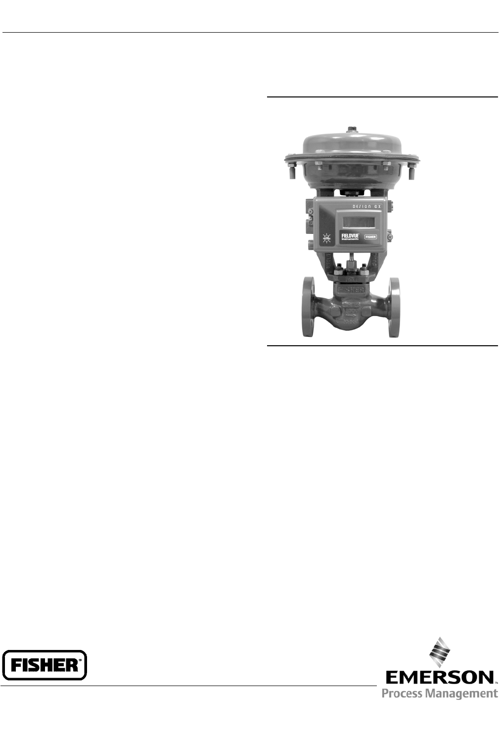
Figure 1. Fisher GX Control Valve, Actuator, and
FIELDVUE DVC2000 Digital Valve Controller
W8861
Introduction
Scope of Manual
This instruction manual includes installation, maintenance, and parts information for the Fisher GX control valve and
actuator system.
Do not install, operate, or maintain a GX valve without being fully trained and qualified in valve, actuator, and
accessory installation, operation, and maintenance. To avoid personal injury or property damage, it is important to
carefully read, understand, and follow all the contents of this manual, including all safety cautions and warnings. If you
have any questions about these instructions, contact your Emerson Process Management sales office before
proceeding.
Description
The GX is a compact, state-of-the-art control valve and actuator system, designed to control a wide range of process
gases, vapors, and fluids.
The GX is rugged, reliable, and easy to select. It requires no actuator sizing -- the actuator selection is automatic once
the valve body construction is selected.
The GX meets the requirements of both EN and ASME standards. It is available with a complete accessory package,
including the FIELDVUE DVC2000 integrated digital valve controller.
Instruction Manual
D103175X012
GX Valve and Actuator
August 2011
Instruction Manual
D103175X012
GX Valve and Actuator
August 2011
2
Table 1. Fisher GX Valve Specifications
Specifications EN ASME
Valve Body Size DN 15, 20, 25, 40, 50, 80, 100, 150 NPS1/2,3/4,1,1-1/2, 2, 3, 4, 6
Pressure Rating PN 10 / 16 / 25 / 40 per EN 1092-1CL150 / 300 per ASME B16.34
End Connections Flanged raised face per EN 1092-1Flanged raised face per ASME B16.5
Valve Body/Bonnet Materials
1.0619 steel ASME SA216 WCC steel
1.4409 stainless steel ASME SA351 CF3M stainless steel
CW2M (sizes DN 25 through DN 100 only) CW2M(NPS1through4only)
ASME SA352 LCC ASME SA352 LCC
CN7M Alloy 20
(sizes DN 25 through DN 100 only)
CN7M Alloy 20
(NPS1through4only)
CDMN Duplex SST
(sizes DN 25 through DN 100 only)
CDMN Duplex SST
(NPS1through4only)
CF3 304L SST
(sizes DN 25 through DN 100 only)
CF3 304L SST
(NPS1through4only)
M35-2(NPS1through4only)
N7M Alloy B2
(NPS1through4only)
Face-to-Face Dimensions Consistent with EN 558-1Series1 Consistent with ANSI/ISA 75.08.01
Shutoff per IEC 60534-4
and ANSI/FCI 70-2
Metal seat -Class IV (standard)
Metal seat -Class V (optional)
PTFE seat -Class VI (optional)(1)
Flow Direction Flow-up (Cavitrol™ III trim, Flow down)
Flow Control Characteristics Equal Percentage and Linear
Trim Style
Port Diameters Trim Style Description
4.8 mm Micro-Flow trim (unbalanced)
9.5, 14, 22 mm Stem-Guided with Contoured Plug (unbalanced)
or Port-Guided with Cavitrol III trim (unbalanced)
36, 46 mm Port-Guided Plug (unbalanced)
70, 90, 136 mm Balanced Trim with Contoured plug or Unbalanced Port-Guided Plug
Handwheel Available as an option
Travel Stop Available as an option
1. For 4.8 to 14 mm ports, Class VI shutoff is achieved without PTFE seat.
Valve Installation
WARNING
Always wear protective gloves, clothing, and eyewear when performing any installation operations to avoid personal
injury.
Personal injury or equipment damage caused by sudden release of pressure or bursting of pressure retaining parts might
result if service conditions exceed those for which the product was intended. To avoid injury or damage, provide a relief
valve for over pressure protection as required by government or accepted industry codes and good engineering practices.
Check with your process or safety engineer for any additional measures that must be taken to protect against process
media.
If installing into an existing application, also refer to the WARNING at the beginning of the Maintenance section in this
instruction manual.
CAUTION
This valve is intended for a specific range of pressures, temperatures and other application specifications. Applying
different pressure and temperatures to the valve could result in parts damage, malfunction of the control valve or loss of
Instruction Manual
D103175X012
GX Valve and Actuator
August 2011
3
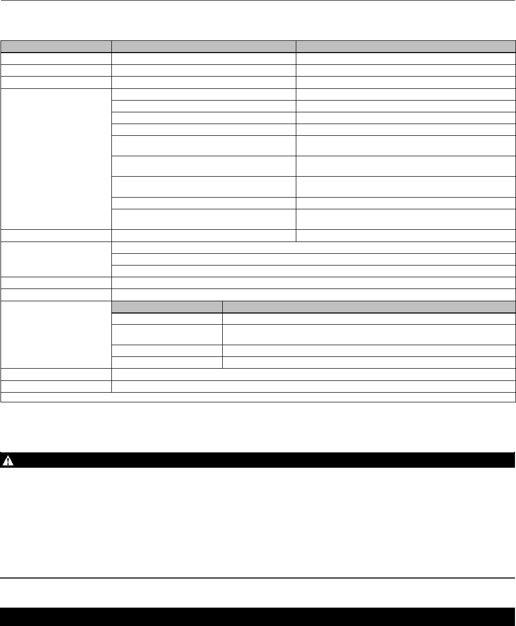
control of the process. Do not expose this product to service conditions or variables other than those for which the product was
intended. If you are not sure what these conditions are you should contact your Emerson Process Management sales office
for more complete specifications. Provide the product serial number (shown on the nameplate, figure 2) and all other
pertinent information.
Figure 2. Fisher GX Nameplate Examples (Key 35)
GE41229-D
WITH SPRING INFORMATION
WITHOUT SPRING INFORMATION
GE01296-H
ELECTRIC ACTUATOR
GG12198-A
WARNING
If you move or work on an actuator installed on a valve with loading pressure applied, keep your hands and tools away from
the stem travel path to avoid personal injury. Be especially careful when removing the stem connector to release all loading
on the actuator stem whether it be from air pressure on the diaphragm or compression in the actuator springs. Likewise
take similar care when adjusting or removing any optional travel stop. Refer to the relevant actuator Maintenance
Instructions.
If hoisting the valve take care to prevent people from being injured in case the hoist or rigging slips. Be sure to use
adequately sized hoists and chains or slings to handle the valve.
1. Before installing the valve, inspect it to be certain that the valve body cavity is free of all foreign material. Clean out
all pipelines to remove scale, welding slag and other foreign material.
2. The control valve assembly may be installed in any orientation unless limited by seismic criteria. However, the
normal method is with the actuator vertical above the valve. Flow through the valve must be in the direction
indicated by the arrow cast on the valve.
3. Use accepted piping practices when installing the valve in the pipeline. Use a suitable gasket between the valve and
the pipeline flanges.

Instruction Manual
D103175X012
GX Valve and Actuator
August 2011
4
4. If continuous operation is required during inspection or maintenance, install isolating valves on either side of the
control valve with a bypass valve to control the flow while the control valve is receiving maintenance.
WARNING
Personal injury could result from packing leakage. Valve packing is tightened before shipment; however the packing might
require some readjustment to meet specific service conditions.
Maintenance
WARNING
Avoid personal injury or property damage from sudden release of process pressure or bursting of parts. Before performing
any maintenance operations:
DDo not remove the actuator from the valve while the valve is still pressurized.
DAlways wear protective gloves, clothing, and eyewear when performing any maintenance operations to avoid personal
injury.
DDisconnect any operating lines providing air pressure, electric power or a control signal to the actuator. Be sure the
actuator cannot suddenly open or close the valve.
DUse bypass valves or completely shut off the process to isolate the valve from the process pressure. Relieve the process
pressure from both sides of the valve.
DDepending on the actuator construction, it will be necessary to manage the pneumatic actuator loading pressure and
any actuator spring pre-compression. It is essential to refer to the relevant actuator instructions in this manual to
ensure safe removal of the actuator from the valve.
DUselock-outprocedurestobesurethattheabovemeasures stay in effect while you work on the equipment.
DThe valve packing box may contain process fluids that are pressurized, even when the valve has been removed from the
pipeline. Process fluids may spray out under pressure when removing the packing hardware or packing rings, or when
loosening the packing box pipe plug.
DCheck with your process or safety engineer for any additional measures that must be taken to protect against process
media.
Note
Whenever a gasket seal is disturbed by removing or shifting gasketed parts, install a new gasket during reassembly. This ensures a
good gasket seal because the used gasket may not seal properly.
Actuator Maintenance
For electric actuators, see the supplier's instruction manual.
The following sections provide procedures for actuator maintenance. Refer to figures 18, 19, 20, and 21.
The actuator soft parts may require periodic replacement. This includes the diaphragm (key 10), diaphragm O-ring
(key 109), actuator rod bushing (key 19), and the actuator rod seal (key 20).
If the actuator stroking direction (air-to-open or air-to-close) is unknown, refer to the nameplate on top of the actuator
casing and figure 2.

Instruction Manual
D103175X012
GX Valve and Actuator
August 2011
5
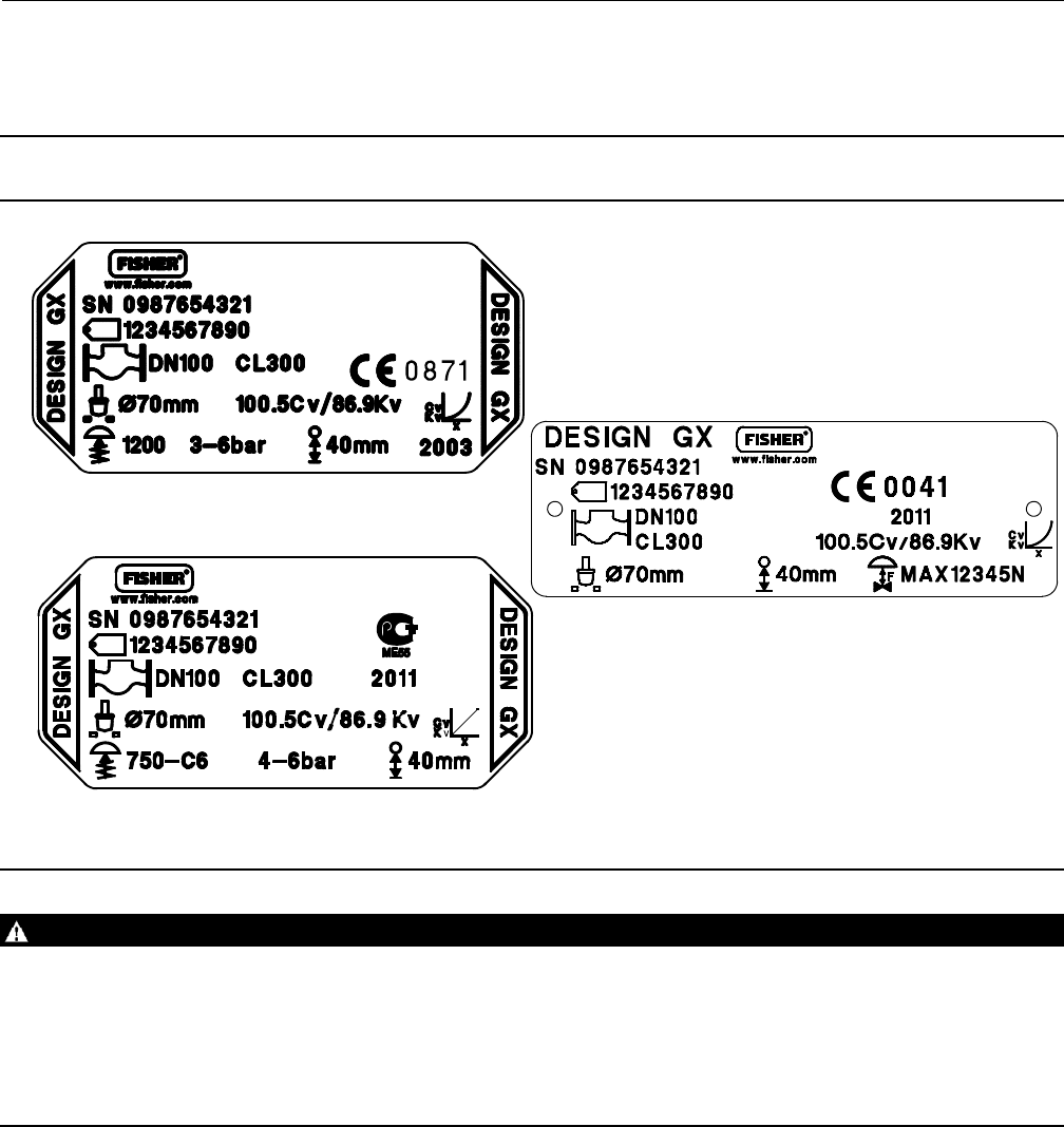
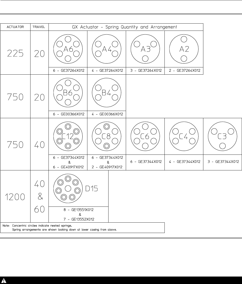
There are several optional actuator constructions, depending on supply pressure. Refer to the nameplate on the top of
the actuator to determine the construction installed. Refer to figure 3 and table 2 for proper spring configuration.
Note
OlderGXactuatornameplatesdonotcontain spring configuration information. If you require replacement springs or wish to
switch to an optional actuator construction, consult your Emerson Process Management sales office.
Note
When the GX actuator is equipped with the integrated FIELDVUE DVC2000 digital valve controller (figure 1), additional
considerations may be required. Refer to the FIELDVUE DVC2000 Digital Valve Controller Mounting section of this manual for
additional instruction.
Actuator Disassembly (For Air-to-Open Constructions - see figures 18 or 19)
1. Connect a separate air supply to the lower diaphragm casing via the air supplyconnectionontheyoke(asshownin
figure 18 or 19) and apply sufficient air pressure to raise the valve plug/stem off the seat to mid-travel.
2. Remove the stem connector nut half (key 23), stem connector bolt half (key 24), and travel indicator (key 26).
3. Push the valve plug/stem (key 3) down until it contacts the seat.
4. Loosen the locknut (key 28) and thread the stem adjustor nut (key 27) down until it clears the top of the valve
plug/stem (key 3).
5. Shut off the air pressure and disconnect the separate air supply to the lower diaphragm casing (as shown in figure
18 or 19).
WARNING
To avoid personal injury or property damage due to actuator springs (keys 12 and 82) being under compression, remove the
long cap screws (key 16) last.
The upper actuator casing may remain fixed to the diaphragm and lower casing during disassembly, even if the casing cap
screws have been loosened. If this happens, the actuator springs are still under compression. The upper casing could
suddenly come loose and jump, due to the compressed energy of the springs. If the upper casing is stuck to the diaphragm
and lower casing when you begin loosening the casing cap screws, pry the casings apart with a prying tool. Always ensure
that the springs are dispersing energy and the upper casing is moving against the long bolts during disassembly.
6. Remove the short actuator casing cap screws and hex nuts (keys 17 and 18) first. Once these have been removed
from the actuator assembly, carefully remove the long actuator cap screws and hex nuts (keys 16 and 18),
alternating between them to gradually release the spring energy (compression).
7. Remove the upper diaphragm casing (key 9) and the actuator springs (key 12 and/or 82).
8. Lift off the actuator stem/diaphragm assembly (includes keys 22, 11, 10, 14, 13, 109, and 15) and remove the cap
screw (key 14), actuator spacer (key 13), actuator rod (key 22), and washer (key 15).
9. Replace the diaphragm (key 10), diaphragm O-ring (key 109), actuator rod bushing (key 19), and actuator rod seal
(key 20), as needed.
Instruction Manual
D103175X012
GX Valve and Actuator
August 2011
6
Figure 3. Spring Configuration
GG00398-B
Actuator Disassembly (For Air-to-Close Constructions - see figure 20 or 21)
1. Remove the stem connector nut half (key 23), stem connector bolt half (key 24), and travel indicator (key 26).
WARNING
To avoid personal injury or property damage due to actuator springs (key 12) being under compression, remove the long
cap screws (key 16) last.
The upper actuator casing may remain fixed to the diaphragm and lower casing during disassembly, even if the casing cap
screws have been loosened. If this happens, the actuator springs are still under compression. The upper casing could
Instruction Manual
D103175X012
GX Valve and Actuator
August 2011
7
suddenly come loose and jump, due to the compressed energy of the springs. If the upper casing is stuck to the diaphragm
and lower casing when you begin loosening the casing cap screws, pry the casings apart with a prying tool. Always ensure
that the springs are dispersing energy and the upper casing is moving against the long bolts during disassembly.
2. Remove the short actuator casing cap screws and hex nuts (keys 17 and 18) first. Once these have been removed
from the actuator assembly, carefully remove the long actuator cap screws and hex nuts (keys 16 and 18),
alternating between them to gradually release the spring energy (compression).
3. Remove the upper diaphragm casing (key 9).
4. Lift off the actuator stem/diaphragm assembly (includes keys 22, 11, 10, 14, 13, 109, and 15) and remove the cap
screw (key 14), actuator spacer (key 13), actuator rod (key 22), and washer (key 15).
5. Remove the actuator springs (key 12 and/or 82).
6. Replace the diaphragm (key 10), diaphragm O-ring (key 109), actuator rod bushing (key 19), and actuator rod seal
(key 20), as needed.
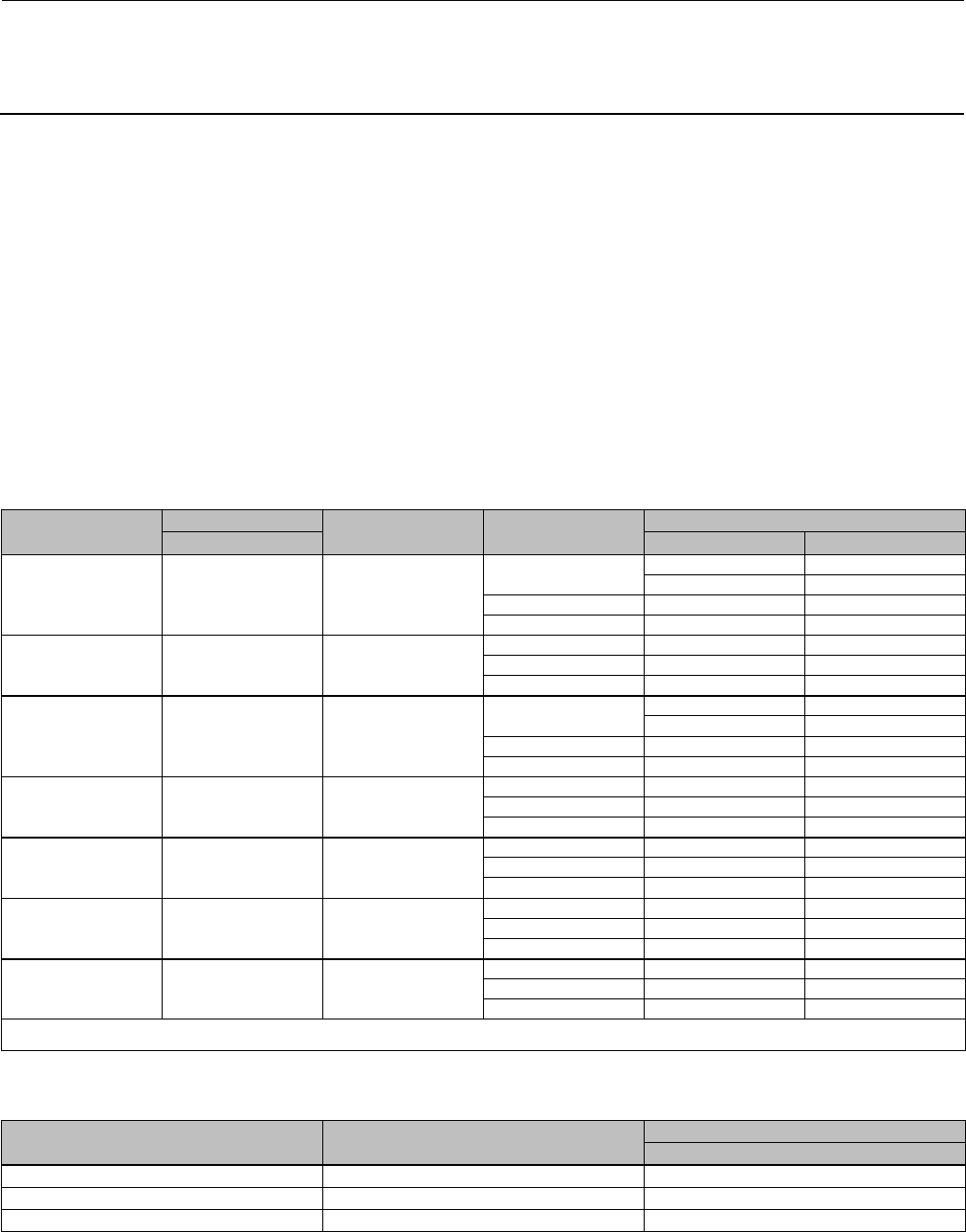
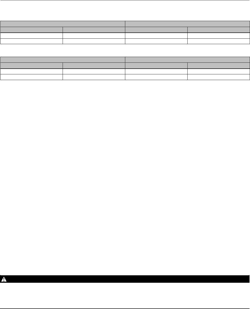
Table 2. Actuator Spring Configuration Based on Minimum Supply Pressure(1)
ACTUATOR SIZE TRAVEL STEM MATERIAL MINIMUM SUPPLY
PRESSURE
SPRING CONFIGURATION
mm Air-to-Open Air-to-Close
225 20 S20910, N05500
S31603
4bar(58psi) A6 A3
A4(2) A4(2)
3bar(44psi) A4 A3
2bar(29psi) A3 A2
225 20 S31803, N10665,
N06022
4bar(58psi) A6 A3
3bar(44psi) A4 A3
2bar(29psi) A3 A2
750 20 S20910, N05500
S31603
4bar(58psi) B6 B4
B6(2) B6(2)
3bar(44psi) B6 B4
2bar(29psi) B4 B4
750 20 S31803, N10665,
N06022
4bar(58psi) B4 B4
3bar(44psi) B4 B4
2bar(29psi) B4 B4
750 40 S20910, N05500
S31603
4bar(58psi) C12 C6
3bar(44psi) C8 C3
2bar(29psi) C4 C3
750 40 S31803, N10665,
N06022
4bar(58psi) C8 C6
3bar(44psi) C8 C3
2bar(29psi) C4 C3
1200 40 or 60 S20910, N05500
S31603
4bar(58psi) D15 D15
3bar(44psi) D15 D15
2bar(29psi) N/A N/A
1. Only applicable to actuators with spring information on the nameplate (see figure 2).
2. Only applicable to Cavitrol III constructions.
Table 3. Fisher GX Maximum Rated Travel
ACTUATOR SIZE NUMBER OF CASING BOLTS TRAVEL
mm
225 620
750 10 20 or 40
1200 16 40 or 60
Instruction Manual
D103175X012
GX Valve and Actuator
August 2011
8
Table 4. Body Nut (Key 7) Torque Requirements
VALVE SIZE TORQUE
NSmlbfSft
DN 15, 20, 25 (NPS 1/2, 3/4, 1) 45.5 33.5
DN 40 (NPS 1-1/2) 79.8 58.9
DN 50 (NPS 2) 79.8 58.9
DN 80 (NPS 3) 163 120
DN 100 and DN 150 (NPS 4 and 6) 282 208
Table 5. Yoke/Extension Bonnet Nut (Key 46) Torque Requirements (used on Extension Bonnet and Bellows Bonnet
constructions)
VALVE SIZE TORQUE
NSmlbfSft
DN 15, 20, 25, 40, and 50 (NPS 1/2, 3/4, 1,
1-1/2, and 2) 79.8 58.9
DN 80 and 100 (NPS 3 and 4) 163 120
Actuator Assembly For Air-to-Open Constructions (or to Change Action to Air-to-Open - see
figure 18 or 19)
1. Install the diaphragm (key 10) on the diaphragm plate (key 11). Insert the cap screw (key 14) through the actuator
spacer (key 13) and place this assembly through the diaphragm/diaphragm plate assembly.
2. Place the diaphragm O-ring (key 109) and the washer (key 15) over the center hole of the diaphragm, so that the
convex part of the washer is facing down toward the diaphragm and contains the O-ring. Ensure the convex part of
the washer is guided in the diaphragm center hole as shown in figure 18 or 19.
3. Screw the actuator rod (key 22) onto the cap screw (key 14) and torque to 80 NSm (59.1 lbfSft). Install the actuator
stem/diaphragm assembly back into the actuator yoke (key 8).
4. Place the actuator springs (key 12 and/or 82) onto the spring locators in the diaphragm plate (key 11). See figure 3
and table 2 for proper spring quantity and arrangement.
DIf the nameplate does not contain spring information, use the same quantity and arrangement as originally
installed.
5. Install the upper diaphragm casing (key 9) so that the ribs on the top of the upper diaphragm casing are
perpendicular with the yoke legs.
DFor size 225 and 750 actuators, install the 2longcap screws (key 16) and hex nuts (key 18) 180 degrees apart from
each other and in line with the actuator yoke legs.
DFor size 1200 actuators, install the 4longcap screws (key 16) and hex nuts (key 18) 90 degrees from each other,
with two of them in line with the actuator yoke legs.
6. Tighten the long cap screws (key 16) and hex nuts (key 18), alternating between them to gradually compress the
springs, until the two casing halves and diaphragm touch.
7. Install the remaining short cap screws (key 17) and hex nuts (key 18) to the casing.
8. Tighten the actuator casing cap screws evenly using a cross-tightening procedure. Torque to 55 NSm(40lbfSft).
9. If you had previously removed the actuator assembly from the valve, place the actuator assembly back onto the
valve body (key 1). Install the four body nuts (key 7), but tighten them only finger-tight.
Instruction Manual
D103175X012
GX Valve and Actuator
August 2011
9
10. Connect a separate air supply to the actuator air supply connection (as shown on the yoke in figure 18 or 19) and
apply sufficient air pressure to raise the actuator rod (key 22) to the travel stop.
Note
If converting from air-to-close to air-to-open action, first move the vent cap (key 21) from the air supply connection on the yoke
leg(seefigure20or21)tothetopofthecasing(seefigure18or19).
11. For standard bonnet constructions (figures 18, 19, 20, and 21), tighten the body nuts (key 7) evenly using a
cross-tightening procedure. See table 4 for torque requirements.
For extension and bellows bonnet constructions (figures 22 and 23), tighten the bonnet nuts (key 46) evenly using a
cross-tightening procedure. See table 5 for torque requirements.
12. With the valve plug/stem (key 3) on the seat, thread the stem adjustor nut (key 27) up until it is the rated travel
distance specified in table 3 from the actuator rod (key 22). Thread the locknut (key 28) up against the stem locknut
and tighten per table 6.
Table 6. Stem Connector Torque Values
PART STEM MATERIAL TORQUE
NSmLbfSft
M8 Stem Connector Cap Screws All 35 26
M10 Stem Connector Jam Nut
(Rie 4606 Coated)
S31603, S20910, N05500 48 35
N06022, S31803, N10665 35 26
M14 Stem Connector Jam Nut S31603, S20910, N05500 175 129
N06022, S31803, N10665 138 102
13. Stroke the actuator rod until it contacts the stem adjuster nut (key 27) and install the stem connector halves and
travel indicator (keys 23, 24, and 26) with the cap screws (key 25). Install the stem connector halves in the proper
orientation so that when looking at the inside of the stem connector halves, the flats are down and the beveled
surfaces are up.
14. Align the pointer of the travel indicator (key 26) with the appropriate mark on the travel scale.
15. Tighten the stem connector cap screws (key 25) to 35 NSm(26lbfSft).
16. Release the actuator pressure.
Note
For air-to-open action, the air supply tubing must be connected to the actuator yoke at the air supply connection, see figure 18 or
19. (If converting from air-to-close to air-to-open, the tubing will need to be re-routed to this location).
Actuator Assembly For Air-to-Close Constructions (or to Change Action to Air-to-Close - see
figure 20 or 21)
1. Position the upper diaphragm casing (key 9) upside down on the bench so that it lays flat and not off balance.
Note
If converting from air-to-open to air-to-close action, first move the vent cap (key 21) from the top of the casing (see figure 18 or
19) and thread into the air supply connection on the yoke leg (see figure 20 or 21).

Instruction Manual
D103175X012
GX Valve and Actuator
August 2011
10
2. Install the diaphragm (key 10) on the diaphragm plate (key 11). Place the diaphragm O-ring (key 109) and the
washer (key 15) over the center hole of the diaphragm, so that the convex part of the washer is facing down toward
the diaphragm and contains the O-ring. Ensure the convex part of the washer is guided in the diaphragm center
hole as shown in figure 20 or 21.
3. Insert the cap screw (key 14) through the washer and diaphragm, install the actuator spacer (key 13), and screw the
actuator rod (key 22) onto the cap screw (key 14) finger-tight.
4. Radially align the spring locators in the diaphragm plate assembly (key 11) with the casing cap screw holes in the
diaphragm (key 10). This will ensure that the springs do not cover the air path in the yoke.
5. Torque the cap screw (key 14) to the actuator rod (key 22) to 80 NSm (59.1 lbfSft) and lay this assembly into the
upper diaphragm casing (key 9).
6. Place the actuator springs (key 12 and/or 82) onto the spring locators in the diaphragm plate (key 11). See figure 3
and table 2 for proper spring quantity and arrangement.
DIf the nameplate does not contain spring information, use the same quantity and arrangement as originally
installed.
7. Remove and replace the actuator rod bushing (key 19) and actuator rod seal (key 20) in the actuator yoke (key 8), if
necessary.
8. Set the actuator yoke (key 8) down onto the assembly that is resting in the upper diaphragm casing (key 9) so that
the yoke legs are perpendicular with the ribs on the top of the upper diaphragm casing (key 9).
DFor size 225 and 750 actuators, install the 2longcap screws (key 16) and hex nuts (key 18) 180 degrees apart from
each other and in line with the actuator yoke legs.
DFor size 1200 actuators, install the 4longcap screws (key 16) and hex nuts (key 18) 90 degrees from each other,
with two of them in line with the actuator yoke legs.
9. Tighten the long cap screws (key 16) and hex nuts (key 18), alternating between them to gradually compress the
springs, until the two casing halves and diaphragm touch.
10. Install the remaining short cap screws (key 17) and hex nuts (key 18) to the casing.
11. Tighten the actuator casing cap screws evenly using a cross-tightening procedure. Torque to 55 NSm(40lbfSft).
12. If you had previously removed the actuator assembly from the valve, place the actuator assembly back onto the
valvebody(key1).For standard bonnet constructions (figures 18, 19, 20, and 21), install the body nuts (key 7) and
tighten evenly using a cross-tightening procedure. See table 4 for torque requirements.
For extension and bellows bonnet constructions (figures 22 and 23), install the bonnet nuts (key 46) and tighten
evenly using a cross-tightening procedure. See table 5 for torque requirements.
13. With the valve plug/stem (key 3) in the closed position (on the seat), thread the stem adjustor nut (key 27) up until
it is at the rated travel (see table 3) from the actuator rod (key 22). Thread the locknut (key 28) up against the stem
locknut and tighten per table 6.
14. Stroke the actuator rod until it contacts the stem adjuster nut (key 27) and install the stem connector halves and
travel indicator (keys 23, 24, and 26) with the cap screws (key 25). Install the stem connector halves in the proper
orientation so that when looking at the inside of the stem connector halves, the flats are down and the beveled
surfaces are up.
15. Align the pointer of the travel indicator (key 26) with the appropriate mark on the travel scale.
16. Tighten the stem connector cap screws (key 25) to 35 NSm(26lbfSft).
Note
For air-to-close action, the air supply tubing must be connected to the actuator upper casing at the air supply connection, see
figure 20 or 21. (If converting from air-to-open to air-to-close, the tubing will need to be re-routed to this location).
Instruction Manual
D103175X012
GX Valve and Actuator
August 2011
11
FIELDVUE DVC2000 Digital Valve Controller Mounting
This section provides instruction on mounting the FIELDVUE DVC2000 digital valve controller to the GX control valve.
For further detail on the operation and maintenance of the DVC2000, refer to the DVC2000 instruction manual.
The FIELDVUE DVC2000 digital valve controller mounts directly to an interface pad on the GX actuator yoke leg,
eliminating the need for mounting brackets (see figure 1). Internal passageways in the actuator route the pneumatic
output to the actuator casing, which eliminates the need for external air supply tubing in the air-to-open
(spring-to-close) constructions. (The GX will also accommodate other valve positioners, using the NAMUR mounting
pads on the side of the yoke legs.)
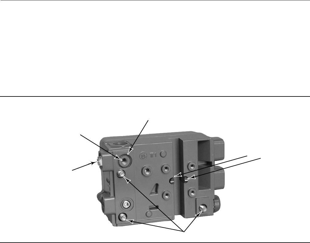
Figure 4. DVC2000 Digital Valve Controller Mounting Details
POLE PIECES
M8 MOUNTING BOLTS
A: EXTERNAL PNEUMATIC
OUTPUT PORT (1/4 NPT OR
G1/4 PLUG)
B: INTEGRAL MOUNTING
PNEUMATIC OUTPUT PORT
(R1/8 PLUG)
FOR AIR-TO-OPEN, INSTALL THE O-RING SEAL BEFORE
MOUNTING TO THE GX ACTUATOR
W9019
The DVC2000 features linkage-less position feedback when mounted to the GX control valve. There are no touching
parts between the controller and the valve stem, which simplifies controller installation. If maintenance is required,
the DVC2000 can be easily removed from the valve.
In the air-to-open (spring-to-close) configuration, the air signal to the actuator casing is supplied through the air
supply connection on the GX actuator yoke leg (see figure 18 or 19). In the air-to-close (spring-to-open) configuration,
the air signal is supplied to the actuator through the air supply connection on the top of the actuator casing (see figure
20 or 21).
For an air-to-open construction, a DVC2000 will mount to the actuator (figure 18 or 19). The air signal is transmitted
to the lower casing through the pneumatic passageway marked “air supply connection” in figure 18 or 19.
For an air-to-close construction, DN 15 through DN 100 (NPS 1/2 through 4) only: in the actuator design (figure 20 or
21), the pneumatic signal is connected directly to the air supply connection in the upper actuator casing. The yoke is
symmetrical and the air passageways serve as a vent, whereby the DVC2000 can be easily moved from one side of the
valve to the other without rotating the actuator.
DVC2000 Mounting Procedures
Steps A and B of the following instructions apply to the actuator construction shown in figures 18, 19, 20, and 21.

Instruction Manual
D103175X012
GX Valve and Actuator
August 2011
12
A. Mounting the DVC2000 to an air-to-open GX actuator (spring-to-close) (see figure 4 and figure 18 or 19):
1. Attach the magnetic feedback array (supplied with the DVC2000) to the valve stem connector using the alignment
template (supplied with the mounting kit) for accurate alignment.
2. Remove the plug (R1/8) from the back of the DVC2000 housing (Port B in figure 4). This pneumatic output port on
the DVC2000 lines up with the integral GX actuator air supply connection (see figure 18 or 19).
3. Install the plug (either G1/4 or 1/4 NPT, included in the mounting kit) to the external output pneumatic port (Port A
in figure 4).
4. Remove the digital valve controller's cover.
5. Using a 6mm hex wrench, attach the digital valve controller to the GX actuator mounting pad on the side that has
the open pneumatic port. Be sure to place the O-ring seal between the digital valve controller's pneumatic output
and the actuator mounting pad (Port B, as shown in figure 4). Pneumatic tubing is not required because the air
passages are internal to the actuator. Also, install the insulating gaskets around the mounting bolts.
6. Check for clearance between the magnet assembly and the DVC2000 feedback slot. The magnet assembly should
be positioned such that the index mark in the feedback slot of the DVC2000 housing is between the valid range on
the magnet assembly throughout the range of travel. (See figure 4).
B. For air-to-close GX actuator (spring-to-open)(seefigure4andfigure20or21):
1. Attach the magnetic feedback array (supplied with the DVC2000) to the valve stem connector using the alignment
template (supplied with the mounting kit) for accurate alignment.
2. In the air-to-close configuration it is required that an R1/8 plug be installed into the integral mount pneumatic port
on the back of the DVC2000 housing (Port B of figure 4).
3. Remove the digital valve controller's cover.
4. Using a 6mm hex wrench, attach the digital valve controller to the GX actuator mounting pad.
Note
The O-ring seal and G1/4 or 1/4 NPT plugs (supplied in the mounting kit) are not used with this actuator construction.
5. Check for clearance between the magnet assembly and the DVC2000 feedback slot. The magnet assembly should
be positioned such that the index mark on the pole pieces (back of the controller housing) is between the marks on
the magnet assembly throughout the range of travel. (See figure 4.)
6. Install tubing between the external pneumatic output connection of the DVC2000 (Port A of figure 4) to the air
supply connection (see figure 20 or 21) on top of the actuator casing.
When changing actuator action:
When field converting a GX actuator from air-to-open to air-to-close closed (or vice-versa), you will need to change the
plugs for the pneumatic passages in the DVC2000 housing.
DTo convert from air-to-close to air-to-open (spring-to-close), remove the R1/8 pneumatic plug on the back of the
DVC2000 housing and install an O-ring (Port B of figure 4). Plug the external pneumatic output with a 1/4 NPT or
G1/4 plug (depending on the housing version). (Port A of figure 4.)
DTo convert from air-to-open to air-to-close (spring-to-open), remove the external pneumatic plug (1/4 NPT or G1/4
plug, depending on the housing version from Port A of figure 4). Install an R1/8 plug on the back of the DVC2000
housing (Port B of figure 4). Install tubing between the pneumatic output connection of the DVC2000
(Port A) to the air supply connection on top of the actuator casing (see figure 20 or 21).
Packing Maintenance
Key numbers refer to figures 15, 18, 19, 20, 21, 22, and 23.

Instruction Manual
D103175X012
GX Valve and Actuator
August 2011
13
Packing Adjustment
For spring-loaded single PTFE V-ring packing (figure 15) or for Graphite ULF packing (figure 16), the Belleville spring
pack (key 34) maintains a sealing force on the packing. If leakage is detected around the packing follower (key 29)
check to be sure that the packing follower (key 29) is tight. Using a wrench, tighten the packing follower (key 29) in
1/4 turn intervals until the leakage is stopped. If leakage cannot be stopped in this manner, proceed to the Replacing
Packing section in this manual.
Replacing Packing (Pneumatic Actuators)
This section provides instruction on replacing packing in standard bonnets, extension bonnets, and bellows extension
bonnets.
Isolate the control valve from the line pressure, release pressure from both sides of the valve body and drain the
process media from both sides of the valve. Shut off all pressure lines to the actuator and release all pressure from the
actuator. Use lock-out procedures to ensure that the above measures stay in effect while you work on the equipment.
1. For air-to-open constructions:
a. Connect a separate air supply to the lower diaphragm casing via the air supply connection on the yoke (as shown
in figure 18 or 19) and apply sufficient air pressure to raise the valve plug/stem off the seat to mid travel.
b. Remove the stem connector nut half (key 23), stem connector bolt half (key 24), and travel indicator (key 26).
c. Push the valve plug stem (key 3) down until it contacts the seat.
d. Loosen the locknut (key 28) and thread the stem adjustor nut (key 27) down until it clears the top of the valve
plug stem (key 3).
e. Shut off the air pressure and disconnect the separate air supply to the lower diaphragm casing (as shown in figure
18 or 19).
2. For air-to-close constructions, as shown in figure 20 or 21, remove the stem connector nut half (key 23), stem
connector bolt half (key 24), and travel indicator (key 26).
WARNING
To avoid personal injury or property damage by uncontrolled movement of the actuator yoke (key 8), loosen the body/yoke
nuts (figures 18, 19, 20, and 21, key 7) or bonnet/yoke nuts (figures 22 and 23, key 46) by following the instructions in the
next step. Do not remove a stuck actuator yoke by pulling on it with equipment that can stretch or store energy in any other
manner. The sudden release of stored energy can cause uncontrolled movement of the actuator yoke.
Note
The following step also provides additional assurance that the valve body fluid pressure has been relieved.
3. For standard bonnet constructions (figures 18, 19, 20, and 21), body nuts (key 7) attach the actuator yoke (key 8)
to the valve body (key 1). Loosen these nuts approximately 3mm (1/8 inch).
For extension and bellows bonnet constructions, bonnet nuts (key 46) attach the actuator yoke (key 8) to the
extension bonnet (key 39). Loosen these nuts approximately 3mm (1/8 inch).
4. Then loosen the valve-to-yoke gasketed joint by either rocking the actuator yoke or prying between the valve and
actuator yoke. Work the prying tool around the actuator yoke until it loosens.

Instruction Manual
D103175X012
GX Valve and Actuator
August 2011
14
WARNING
If there is evidence of process fluid under pressure leaking from the joint, retighten the valve body/joint nuts and return to
the Warning at the beginning of the Maintenance section to ensure proper steps have been taken to isolate the valve and
relieve process pressure, thus avoiding property damage or personal injury.
5. If no fluid leaks from the joint, loosen the packing follower (key 29) two turns to relieve the packing compression
load.
6. For standard bonnet constructions (figures 18, 19, 20, and 21), remove the body nuts (key 7) completely.
For extension and bellows bonnet constructions (figures 22 and 23), remove the bonnet nuts (key 46) completely.
CAUTION
To avoid property damage, place the actuator yoke on a protective surface, as described in the following procedure.
7. Carefully lift off the actuator yoke and set it on a protective surface to prevent damage.
For standard bonnet constructions, if the bonnet (key 4) together with the valve stem plug assembly has a tendency
to lift with the actuator yoke, ensure it does not drop from the actuator.
For extension and bellows constructions, ensure the bonnet (key 4) does not lift with the actuator yoke.
For DN150 balanced constructions, if the bonnet, guide sleeve, or valve stem assembly have a tendency to lift with
the actuator yoke, ensure they do not drop from the actuator.
CAUTION
For extension and bellows bonnet constructions, lifting the bonnet with the actuator yoke may cause possible damage to
the valve plug and to the bellows.
8. Remove the stem adjustor nut (key 27) and locknut (key 28).
9. For standard bonnet constructions, remove the bonnet and the valve plug/stem assembly and set on a protective
surface.
For extension and bellows bonnet constructions, remove only the bonnet (key 4).
For DN150 balanced constructions, remove the guide sleeve, bonnet, and valve plug stem assembly.
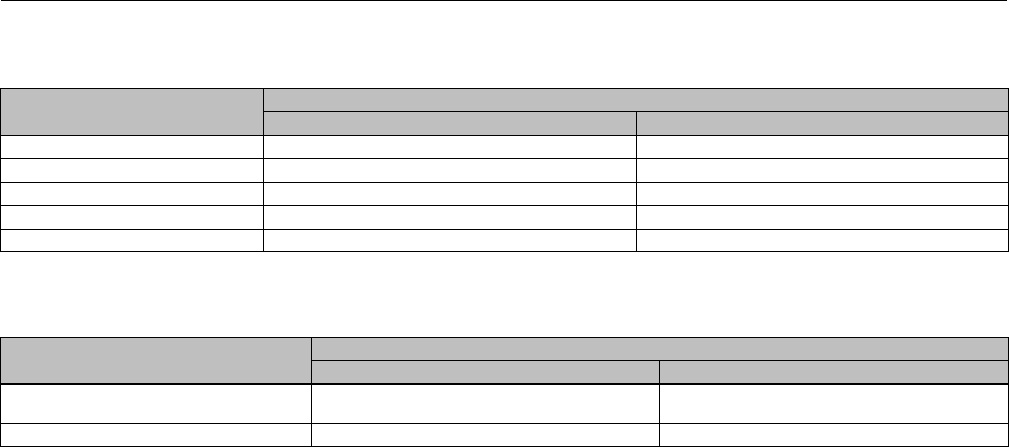
Table 7. Packing Follower Torque
Valve Size Packing Style Torque NSm(lbfSft) Packing Style Torque NSm(lbfSft)
DN15, 20, 25, 40, and 50 PTFE 10 (7.4) ULF 35 (26)
DN80 and 100 PTFE 23 (17) ULF 50 (37)
DN150 PTFE 36 (26) ULF 68 (50)
10. Remove the valve/yoke gasket (figures 18, 19, 20, and 21 key 5, figures 22 and 23 key 47) and cover the opening
of the valve to protect the gasket surface and prevent foreign matter from getting into the valve cavity.
11. Remove the packing follower (key 29) from the bonnet (key 4).
12. Remove the Belleville spring pack (key 34) and packing spacer (key 30) from the bonnet (key 4). Carefully push out
the remaining packing box parts from the bonnet (key 4) using a rounded rod or other tool which will not scratch
the packing box wall. Clean the packing box and the metal packing box parts.

Instruction Manual
D103175X012
GX Valve and Actuator
August 2011
15
CAUTION
Inspect the valve stem, threads and packing box surfaces for any sharp edges that might cut the packing. Scratches or burrs
could cause packing box leakage or damage the new packing.
13. Inspect the valve stem, threads and packing box surfaces for any sharp edges that might cut the packing.
Scratches or burrs could cause packing box leakage or damage the new packing. If the surface condition cannot be
improved by light sanding, replace the damaged parts.
14. Remove the covering protecting the valve cavity and install a new valve/yoke gasket (figures 18, 19, 20, and 21
key 5, figures 22 and 23 key 47) making sure that the gasket seating surfaces are clean and smooth.
For DN150 balanced constructions, two gaskets are required; one between the valve body and guide sleeve, and
the other between the guide sleeve and bonnet. Ensure the gasket seating surfaces are clean and smooth for both
gaskets.
15. Carefully install the bonnet (key 4) onto the valve stem.
16. Install the new packing and the metal packing box parts according to figure 15 for PTFE packing and according to
figure 16 for Graphite ULF packing. Place a smooth-edged pipe over the valve stem and gently tap each soft packing
part into the packing box. Apply anti-seize lubricant to the threads and install the packing follower (key 29).
17. Install the locknut (key 28) and stem adjustor nut (key 27).
For standard bonnet constructions, install the valve plug/bonnet sub assembly into the valve body (key 1).
18. Mount the actuator onto the valve and install the body nuts (figures 18, 19, 20, 21 key 7, figures 22 and 23 key
46), but tighten them only finger-tight.
19. For air-to-open, connect a separate air supply to the lower diaphragm casing air supply connection (as shown in
figure 18 or 19) and apply sufficient air pressure to raise the actuator rod (key 22) to the travel stop. Proceed to the
next step.
For air-to-close, proceed to the next step.
20. For standard bonnet constructions, tighten the body nuts (key 7) evenly using a cross-tightening procedure. See
table 4 for torque requirements.
For extension and bellows bonnet constructions, tighten the bonnet nuts (key 46) evenly using a cross-tightening
procedure. See table 5 for torque requirements.
21. Thread the stem lock adjustor (key 27) up until it is the rated travel distance specified in table 3 from the actuator
rod (key 22). Thread the locknut (key 28) up against the stem locknut and tighten to the torque specified in table 6.
22. Stroke the actuator rod until it contacts the stem adjuster nut (key 27) and install the stem connector halves and
travel indicator (keys 23, 24, and 26) with the cap screws (key 25). Install the stem connector halves in the proper
orientation so that when looking at the inside of the stem connector halves, the flats are down and the beveled
surfaces are up.
23. Align the pointer of the travel indicator (key 26) with the appropriate mark on the travel scale.
24. Tighten the stem connector cap screws (key 25) to 35 Nm(26lbfft).
Table 8. Seat Ring / Cage Torque Requirements
VALVE SIZE TORQUE
DN NPS NSmlbfSft
15, 20, 25 1/2, 3/4, 1 170 124
40 1-1/2 320 234
50 2460 337
80 31020 747
100 41520 1113
150 63400 2500
Instruction Manual
D103175X012
GX Valve and Actuator
August 2011
16
Table 9. Stem Extension Torque Requirements
VALVE SIZE TORQUE
DN NPS NmLbfft
15, 20, 25, 40, 50 1/2, 3/4, 1, 1-1/2, 2 40 30
80, 100 3, 4 120 89
Table 10. Bellows Nut Torque Requirements
VALVE SIZE TORQUE
DN NPS NmLbfft
15, 20, 25, 40, 50 1/2, 3/4, 1, 1-1/2, 2 350 260
80, 100 3, 4 650 480
25. Tighten the packing follower (key 29) to the torque specified in table 7.
Alternately, the packing follower can be tightened by the following method:
a. Tighten the packing follower until the Belleville springs are compressed 100% (or completely flat), as detected by
a rapid increase in nut torque.
b. For DN 15 through DN 100 (NPS 1/2 through 4), loosen the packing follower 60_of rotation.
For DN 150 (NPS 6), loosen the packing follower 90_of rotation.
26. For air-to-open, release the actuator pressure.
27. For air-to-open, ensure the vent (key 21) is installed into the upper diaphragm casing (see figure 18 or 19).
For air-to-close, ensure the vent (key 21) is installed into the actuator yoke air supply connection (see figure 20 or
21).
Replacing Packing (Electric Actuators)
This section provides instruction on replacing packing in standard bonnets, extension bonnets, and bellows extension
bonnets.
Isolate the control valve from the line pressure, release pressure from both sides of the valve body and drain the
process media from both sides of the valve. Use lock-out procedures to ensure that the above measures stay in effect
whileyouworkontheequipment.
1. Stroke the actuator so the valve plug/stem (key 3) is at mid travel.
2. Remove the stem connector nut half (key 23), stem connector bolt half (key 24), and travel indicator (key 26).
3. Use precaution to ensure the actuator is locked in position and cannot stroke.
4. Mark the position of the locknut (key 28) on the stem for reassembly.
5. Push the valve plug/stem (key 3) down until it contacts the seat.
6. Loosen the locknut (key 28) and thread the stem adjustor nut (key 27) down until it clears the top of the valve plug
stem (key 3).
WARNING
To avoid personal injury or property damage by uncontrolled movement of the actuator yoke (key 8), loosen the body/yoke
nuts (figures 18, 19, 20, and 21, key 7) or bonnet/yoke nuts (figures 22 and 23, key 46) by following the instructions in the
following step 7. below. Do not remove a stuck actuator yoke by pulling on it with equipment that can stretch or store
energy in any other manner. The sudden release of stored energy can cause uncontrolled movement of the actuator yoke.

Instruction Manual
D103175X012
GX Valve and Actuator
August 2011
17
Note
The following step also provides additional assurance that the valve body fluid pressure has been relieved.
7. For standard bonnet constructions (figures 18, 19, 20, and 21), body nuts (key 7) attach the actuator yoke (key 8)
to the valve body (key 1). Loosen these nuts approximately 3mm (1/8 inch).
For extension and bellows bonnet constructions, bonnet nuts (key 46) attach the actuator yoke (key 8) to the
extension bonnet (key 39). Loosen these nuts approximately 3mm (1/8 inch).
8. Then loosen the valve-to-yoke gasketed joint by either rocking the actuator yoke or prying between the valve and
actuator yoke. Work the prying tool around the actuator yoke until it loosens.
WARNING
If there is evidence of process fluid under pressure leaking from the joint, retighten the valve body/joint nuts and return to
the Warning at the beginning of the Maintenance section to ensure proper steps have been taken to isolate the valve and
relieve process pressure, thus avoiding property damage or personal injury.
9. If no fluid leaks from the joint, loosen the packing follower (key 29) two turns to relieve the packing compression
load.
10. For standard bonnet constructions (figures 18, 19, 20, and 21), remove the body nuts (key 7) completely.
For extension and bellows bonnet constructions (figures 22 and 23), remove the bonnet nuts (key 46) completely.
CAUTION
To avoid property damage, place the actuator yoke on a protective surface, as described in the following procedure.
11. Carefully lift off the actuator yoke and set it on a protective surface to prevent damage.
For standard bonnet constructions, if the bonnet (key 4) together with the valve stem plug assembly has a tendency
to lift with the actuator yoke, ensure it does not drop from the actuator.
For extension and bellows constructions, ensure the bonnet (key 4) does not lift with the actuator yoke.
CAUTION
For extension and bellows bonnet constructions, lifting the bonnet with the actuator yoke may cause possible damage to
the valve plug and to the bellows.
12. Remove the stem adjustor nut (key 27) and locknut (key 28).
13. For standard bonnet constructions, remove the bonnet and the valve plug/stem assembly and set on a protective
surface.
For extension and bellows bonnet constructions, remove only the bonnet (key 4).
14. Remove the valve/yoke gasket (figures 18, 19, 20, and 21 key 5, figures 22 and 23 key 47) and cover the opening
of the valve to protect the gasket surface and prevent foreign matter from getting into the valve cavity.
15. Remove the packing follower (key 29) from the bonnet (key 4).
Instruction Manual
D103175X012
GX Valve and Actuator
August 2011
18
16. Remove the Belleville spring pack (key 34) and packing spacer (key 30) from the bonnet (key 4). Carefully push out
the remaining packing box parts from the bonnet (key 4) using a rounded rod or other tool which will not scratch
the packing box wall. Clean the packing box and the metal packing box parts.
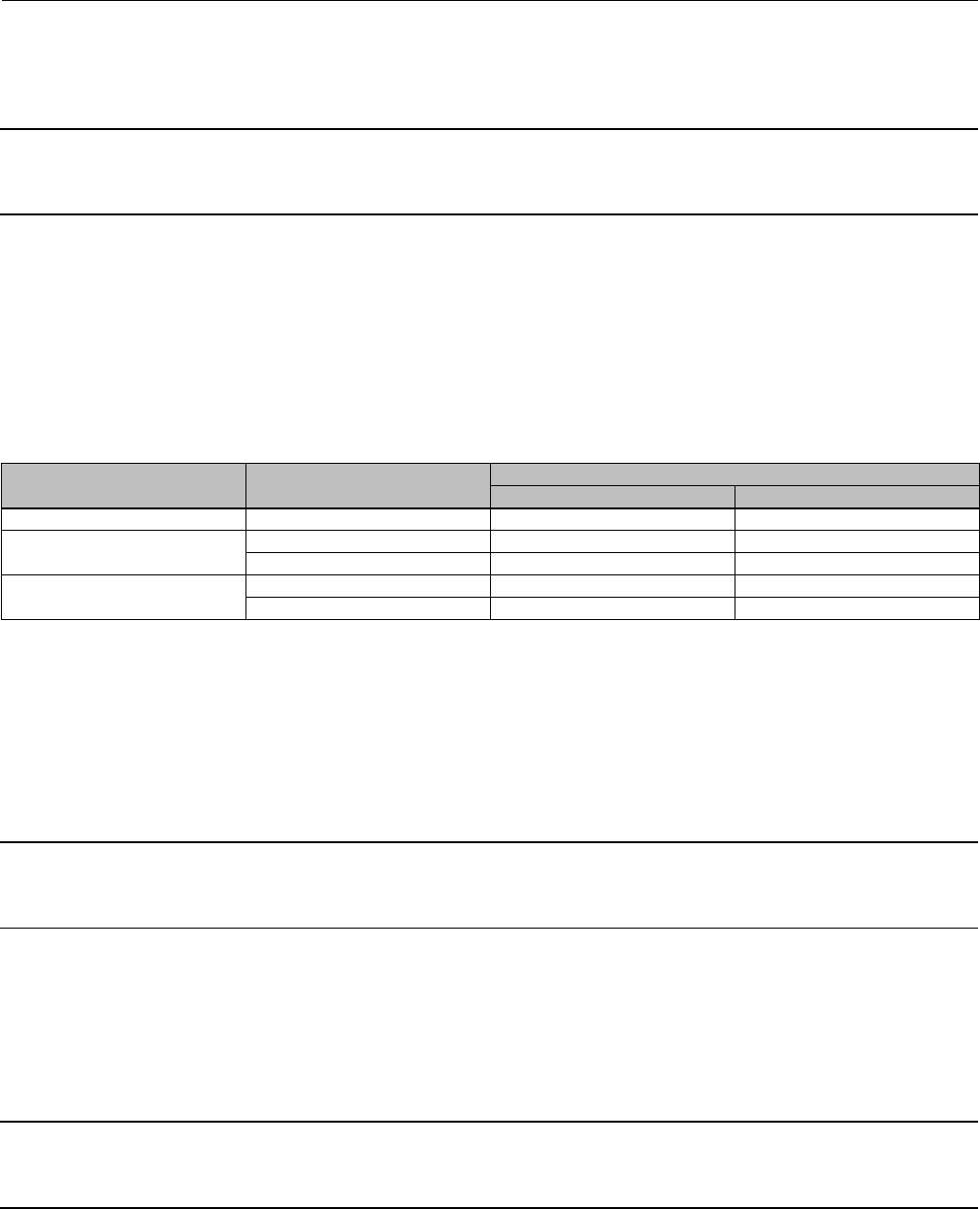
Table 11. GX Electric Actuator Maximum Allowable Thrust
VALVE SIZE STEM DIAMETER TRAVEL BONNET STYLE STEM MATERIAL
STRENGTH
MAXIMUM THRUST
mm mm Nlbf
DN25-DN50
(NPS 1 to 2) 10 20
Plain High(1) 17000 3820
Low(2) 7600 1710
Bellows/Extension High 11400 2560
Low 6700 1500
DN80-DN100
(NPS 3 to 4) 14 20, 40
Plain High 20000 4500
Low 20000 4500
Bellows/Extension High 20000 4500
Low 14500 3260
1. High strength stem materials consist of S200910, N05500, S31603.
2. Low strength materials consist of S31803, N10665, N06022.
CAUTION
Inspect the valve stem, threads and packing box surfaces for any sharp edges that might cut the packing. Scratches or burrs
could cause packing box leakage or damage the new packing.
17. Inspect the valve stem, threads and packing box surfaces for any sharp edges that might cut the packing.
Scratches or burrs could cause packing box leakage or damage the new packing. If the surface condition cannot be
improved by light sanding, replace the damaged parts.
18. Remove the covering protecting the valve cavity and install a new valve/yoke gasket (figures 18, 19, 20, and 21
key 5, figures 22 and 23 key 47) making sure that the gasket seating surfaces are clean and smooth.
19. Carefully install the bonnet (key 4) onto the valve stem.
20. Install the new packing and the metal packing box parts according to figure 15 for PTFE packing and according to
figure 16 for Graphite ULF packing. Place a smooth-edged pipe over the valve stem and gently tap each soft packing
part into the packing box. Apply anti-seize lubricant to the threads and install the packing follower (key 29).
21. Install the locknut (key 28) and stem adjustor nut (key 27). Ensure they are aligned with the mark made on the
stem disassembly and tighten
For standard bonnet constructions, install the valve plug/bonnet sub assembly into the valve body (key 1).
22. Mount the actuator onto the valve and install the body nuts (figures 18, 19, 20, 21 key 7, figures 22 and 23 key
46), but tighten them only finger-tight.
23. For standard bonnet constructions, tighten the body nuts (key 7) evenly using a cross-tightening procedure. See
table 4 for torque requirements.
For extension and bellows bonnet constructions, tighten the bonnet nuts (key 46) evenly using a cross-tightening
procedure. See table 5 for torque requirements.
24. Push the valve plug/stem to the valve seat. Thread the stem adjustor nut (key 27) and locknut (key 28) to the
previously marked position. Thread the locknut (key 28) up against the stem locknut and tighten to the torque
specified in table 6.
25. Stroke the actuator rod until it contacts the stem adjuster nut (key 27) and install the stem connector halves and
travel indicator (keys 23, 24, and 26) with the cap screws (key 25). Install the stem connector halves in the proper
orientation so that when looking at the inside of the stem connector halves, the flats are down and the beveled
surfaces are up.
26. Align the pointer of the travel indicator (key 26) with the appropriate mark on the travel scale.

Instruction Manual
D103175X012
GX Valve and Actuator
August 2011
19
27. Tighten the stem connector cap screws (key 25) to 35 Nm(26lbfft).
28. Tighten the packing follower (key 29) to the torque specified in table 7.
Alternately, the packing follower can be tightened by the following method:
a. Tighten the packing follower until the Belleville springs are compressed 100% (or completely flat), as detected by
a rapid increase in nut torque.
b. For DN 15 through DN 100 (NPS 1/2 through 4), loosen the packing follower 60_of rotation.
29. Ensure that the electric actuator maximum thrust output does not exceed the values in table 11.
Valve Trim Maintenance
Key numbers in this section refer to figures 18, 19, 20, 21, 22, and 23.
Valve Trim Disassembly
1. Remove the actuator and bonnet assembly as described in the Replacing Packing section (steps 1 through 10).
DFor standard bonnet constructions (figures 18, 19, 20, 21, and 25), proceed to the Seat Ring / Cage Removal
section.
DFor extension bonnet constructions (figure 22), proceed to step 3.
DFor bellows bonnet constructions (figure 23), proceed to step 2.
2. For bellows bonnet constructions (figure 23), use a bellows nut tool made according to the dimensions in figure 26
and table 13 to remove the bellows nut (key 51) as follows:
a. Insert the bellows nut tool into the extension bonnet (key 39). Be certain the tool lugs are engaged in the
corresponding recesses in the bellows nut.
b. Use a torque gun or driver having sufficient torque capabilities according to table 10. Connect the gun to a
socket that snugly fits the hex head on the bellows nut tool.
c. Insert the socket onto the hex head of the bellows nut tool.
WARNING
Be careful to hold the torque gun, attached socket, and tool at right angles to the bellows nut when applying torque. Tilting
the gun and socket while applying torque may cause the lugs on the bellows nut tool to suddenly disengage from the lugs
on the bellows nut thus causing possible damage to the bellows nut and possible personal injury.
d. Remove the bellows nut (key 51).
3. For both extension and bellows bonnet constructions: Body nuts (key 7) attach the extension bonnet (key 39) to the
valve body (key 1). Loosen these nuts approximately 3mm (1/8 inch). Then loosen the extension bonnet-to-body
gasketed joint by either rocking the extension bonnet or prying between the body and extension bonnet. Work the
prying tool around the extension bonnet until it loosens.
4. Removethebodynuts(key7)completelyandcarefullylift the extension bonnet (key 39), and valve plug/stem
extension assembly (key 3, 40 and 48) or plug/bellows/stem extension assembly (key 3, 49 and 48) from the top of
the valve body.

Instruction Manual
D103175X012
GX Valve and Actuator
August 2011
20
5. Use a wrench to unscrew the plug/stem assembly (key 3) from the stem extension (key 40) or from bellows/stem
assembly (key 49) as follows:
a. Insert the wrench onto the stem extension hex flats (see figures 22 and 23).
CAUTION
In the following procedure, take precautions to ensure the valve plug and stem finish are not damaged.
b. Clamp the plug/stem assembly (key 3) and holding it stable, unscrew the stem extension (key 40) or
bellows/stem assembly (key 49). Take precautions to ensure the valve plug and stem finish are not damaged.
Note
There is a stem assembly locking insert (figures 22 and 23, key 48) in the valve plug/stem extension assembly. It is possible this
insert may drop out during stem disassembly. If this is the case, ensure it is retained for reassembly of the valve stem to the stem
extension.
6. Remove the plug/stem assembly (key 3) and bellows/stem assembly (key 49) from the extension bonnet. Remove
the bellows gasket (key 50).
7. Proceed to the Seat Ring Removal section.
Seat Ring / Cage Removal
CAUTION
Use care to avoid damaging the gasket sealing surfaces.
The surface finish of the valve stem (key 3) is critical for making a good packing seal. The seating surfaces of the seat ring
(key 2), cage (key 99), and the valve plug (key 3) are critical for tight shutoff and should therefore also be treated with care
and properly protected.
1. Packing parts can be removed from the bonnet if desired. Replace these parts as described in the section on Packing
Maintenance.
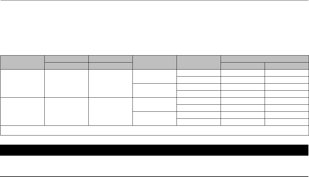
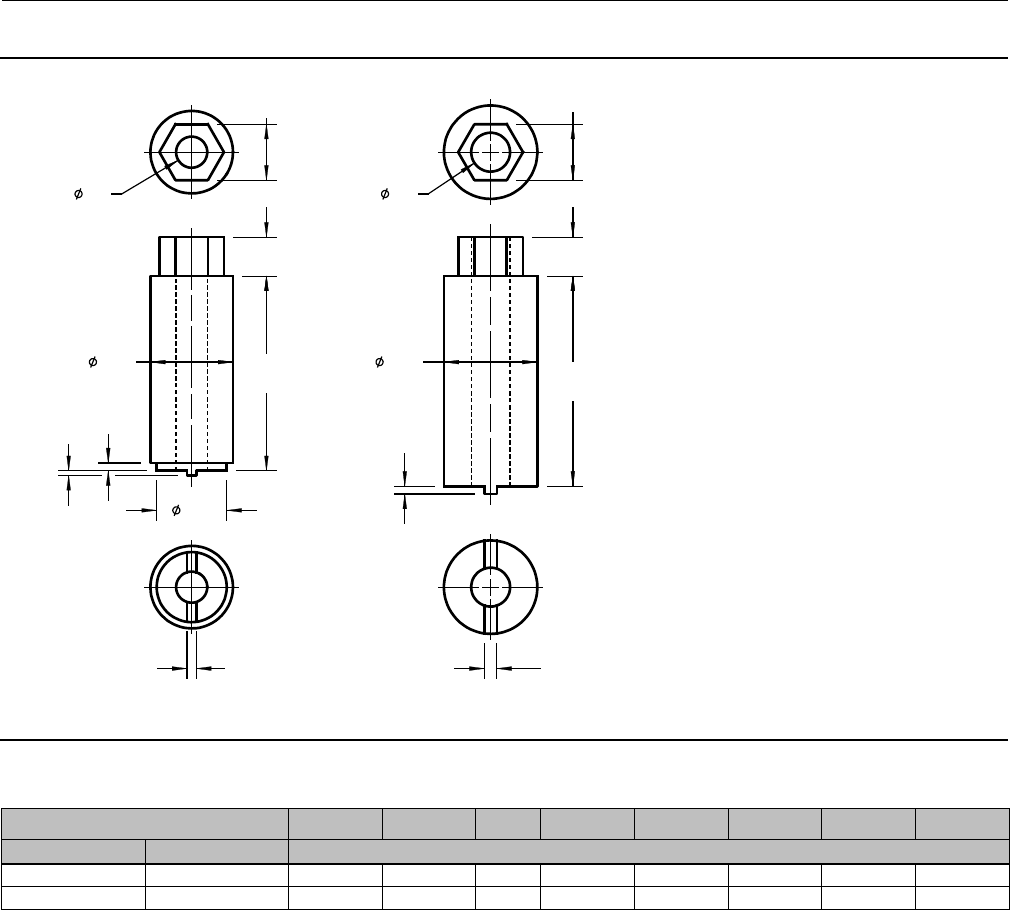
2. Use a seat ring tool made according to the dimensions in figure 5 and table 12 to remove the seat ring (key 2) as
follows:
a. Insert the tool into the valve body. Be certain the tool lugs are engaged in the corresponding recesses in the seat
ring.
b. Use a torque gun or driver having sufficient torque capabilities according to table 8. Connect the gun to a socket
that snugly fits the hex head on the seat ring tool.
c. Insert the socket onto the hex head of the seat ring tool.
WARNING
Be careful to hold the torque gun, attached socket, and tool at right angles to the seat ring when applying torque. Tilting
the gun and socket while applying torque may cause the lugs on the seat ring tool to suddenly disengage from the lugs on
the seat ring thus causing possible damage to the seat ring and possible personal injury.
Instruction Manual
D103175X012
GX Valve and Actuator
August 2011
21
Figure 5. Seat Ring Removal and Installation Tool
GE02918-6
AA
G
B
B
H
DF
E
CC
C
DF
E
DN15, 20, 25
(NPS 1/2, 3/4, 1)
DN40, 50, 80, 100
(NPS 1-1/2, 2, 3, 4)
A
B
E
F
C
C
J
KD
DN150
(NPS 6)
DN25 Cav III
(NPS 1)
GG01215
C
F
G
D
E
H
B
A
Table 12. Seat Ring Removal and Installation Tool Dimensions
Valve Size Part Number A B C D E FGHJK
DN NPS mm
15, 20, 25 1/2, 3/4, 1 GE02918X012 24 15 15.2 954 40 45 10 --- ---
25 (Cavitrol III) 1 (Cavitrol III) Not Available 24 18 13 630 39 45 10 --- ---
40(1) 1-1/2(1) GE02918X022 36 20 2X 13.2 7.5 58 53 --- --- --- ---
50(1) 2(1) GE02918X032 46 28 2X 13.2 7.5 63 63 --- --- --- ---
80 3GE02918X042 60 36 2X 15.2 8.5 100 93 --- --- --- ---
100 4GE02918X052 70 44 2X 17.2 9.5 114 113 --- --- --- ---
150 6GE02918X062 100 50 2X 43 10.5 170.5 174 --- --- 153 20
1. Also used for Cavitrol III cage removal.
3. Remove the seat ring (key 2) from the valve body.
4. Inspectpartsforwearordamagethatwouldprevent proper operation of the valve body.
5. Replace trim parts as necessary.
Valve Trim Assembly
Assembly of Unbalanced Trim
Refer to figures 12, 18, 19, 20, 21, 22, 23, and 25.

Instruction Manual
D103175X012
GX Valve and Actuator
August 2011
22
1. Before installing the new seat ring / cage, thoroughly clean the threads in the valve body port. Apply suitable
lubricant to the threads and to the 60surface of the new seat ring (key 4). Screw the seat ring into the valve body.
Using the seat ring tool, tighten the seat ring and torque according to the values in table 8. Remove all excess
lubricant after tightening.
2. For standard bonnet constructions, perform the following. (Proceed to step 3 for extension and bellows bonnets.)
a. Clean the body/yoke gasket seating surfaces and install a new body/yoke gasket (key 5).
b. Remove any protective tape or covering from the valve plug/stem assembly.
c. Insert the valve plug/stem assembly into the seat ring.
CAUTION
If the packing is to be reused and was not removed from the bonnet, perform the following step carefully to avoid
damaging the packing with the stem threads.
d. Install bonnet and actuator yoke onto the valve body by completing the assembly according to steps 15 to 27 of
the section Replacing Packing, omitting step 16 if new packing is not being installed.
3. For extension and bellows bonnet constructions, perform the following.
a. For bellows bonnet constructions, clean the extension bonnet/bellows gasket seating surfaces and install a new
bellows gasket (key 50).
b. Remove any protective tape or covering from the valve plug/stem assembly (key 3). Then insert the plug/stem
assembly (key 3) through the extension bonnet bushing (key 41).
c. Remove any protective tape or covering from the stem extension (key 40) or the bellows stem assembly (key 49).
Screw the plug/stem assembly (key 3) into the stem extension or bellows/stem assembly. Note: Do not apply
lubricant to the threads of the plug/stem assembly (key 3) or the bellows/stem assembly (key 49).
Note
Ensure the stem assembly locking insert (figures 22 and 23, key 48) has been first inserted in the bottom of the threaded hole in
the stem extension.
CAUTION
In the following procedure, take precautions to ensure the valve plug and stem finish are not damaged.
d. Clamptheplug/stemassembly(key3)andholditstable. Using a box spanner tool tighten the plug/stem
assembly (key 3) into the stem extension (key 40) or into the bellows/stem assembly (key 49) according to the
stem extension torque requirements listed in table 9. Take precautions to ensure the valve plug and stem finish
are not damaged.
e. For bellows bonnet constructions, apply suitable lubricant to the threads and to the bottom surface of the
bellows nut (key 51). Screw the bellows nut into the extension bonnet. Using the bellows nut tool, a lathe or
boring mill, tighten the bellows nut or torque according to the values in table 10. Remove all excess lubricant.

Instruction Manual
D103175X012
GX Valve and Actuator
August 2011
23
f. Clean the body/extension bonnet seating gasket surface and install the gasket (key 5).
g. Install the extension bonnet and plug/stem assembly onto the valve body. Install the body/yoke nuts (key 7) and
tighten evenly using a cross-tightening procedure. See table 4 for torque requirements.
CAUTION
If the packing is to be reused and was not removed from the bonnet, perform the following step carefully to avoid
damaging the packing with the stem threads.
h. Install the bonnet and actuator yoke onto the extension bonnet by completing the assembly according to steps
15 to 27 of the section Replacing Packing, omitting step 16 if new packing is not being installed.
Assembly of Balanced Trim
(Available in DN 80, 100, and 150 [NPS 3, 4, and 6] only)
Refer to figure 10.
CAUTION
To protect the valve plug seal ring (key 37) and to ensure it seals properly, be careful not to scratch the surfaces of the ring
groove in the valve plug or any of the surfaces of the replacement ring.
1. With the valve plug (key 3) removed according to the Disassembly portion of the Valve Trim Maintenance
procedure, proceed as appropriate:
The seal ring (key 37) cannot be reused because it is a closed ring which must be pried and/or cut from the groove.
Once the seal ring is removed, the elastomeric backup ring (key 38), which is also a closed ring, can be pried from the
groove.
To install a new backup ring and seal ring onto the valve plug, apply a general purpose silicone-base lubricant to both
rings (keys 38 and 37). Place the backup ring over the valve plug (key 3) and into the groove. Place the seal ring over
the top edge of the valve plug (key 3) so that it enters the groove on one side of the valve plug. Slowly and gently
stretch the seal ring and work it over the top edge of the valve plug. The PTFE material in the seal ring must be
permitted time to cold-flow during the stretching procedure, so avoid jerking sharply on this ring. Stretching the seal
ring over the valve plug may make it seem unduly loose when in the groove, but it will contract to its original size after
insertion into the bonnet.
2. Install the seat ring, valve plug/stem, bonnet and actuator yoke into the valve body by completing the assembly
according to steps 1 to 3 of the section Assembly of Unbalanced Trim.
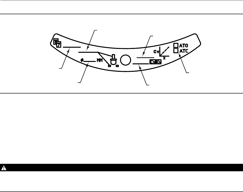
Repair Nameplate
If required by the end-user, an optional repair nameplate is available for recording changes made to the valve trim
during maintenance (see figure 29). This nameplate can be ordered as a spare part, and is easily mounted to the
actuator casing using a casing bolt. (Reference the Parts Ordering section of this manual.)
As shown in figure 29, the repair nameplate provides locations for maintenance personnel to record trim data, such as:
Instruction Manual
D103175X012
GX Valve and Actuator
August 2011
24
DDate of maintenance
DTrim material
DPort diameter
DFlow capacity (Cv/K
v)
DFlow characteristic
DActuator Action ATO/ATC
Bellows Maintenance
This section provides instruction on the replacement of the bellows / stem assembly (see key 49 in figure 23).
1. Remove the actuator, bonnet assembly as described in the Replacing Packing section (steps 1 through 10).
2. Remove the plug/stem assemblies as described in the Valve Trim Disassembly section (steps 2 through 6).
3. To install the new bellows / stem assembly (key 49), perform the Valve Trim Assembly (step 3).
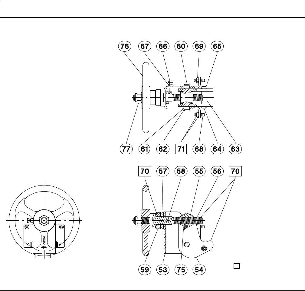
Figure 6. Fisher GX Handwheel Assembly
GE11642-1 AIR-TO-CLOSE, SPRING-TO-OPEN AIR-TO-OPEN, SPRING-TO-CLOSE
STUD AND
NUT (4) STUD AND
NUT (4)
LOCKING
SCREW
LOCKING
SCREW
Instruction Manual
D103175X012
GX Valve and Actuator
August 2011
25
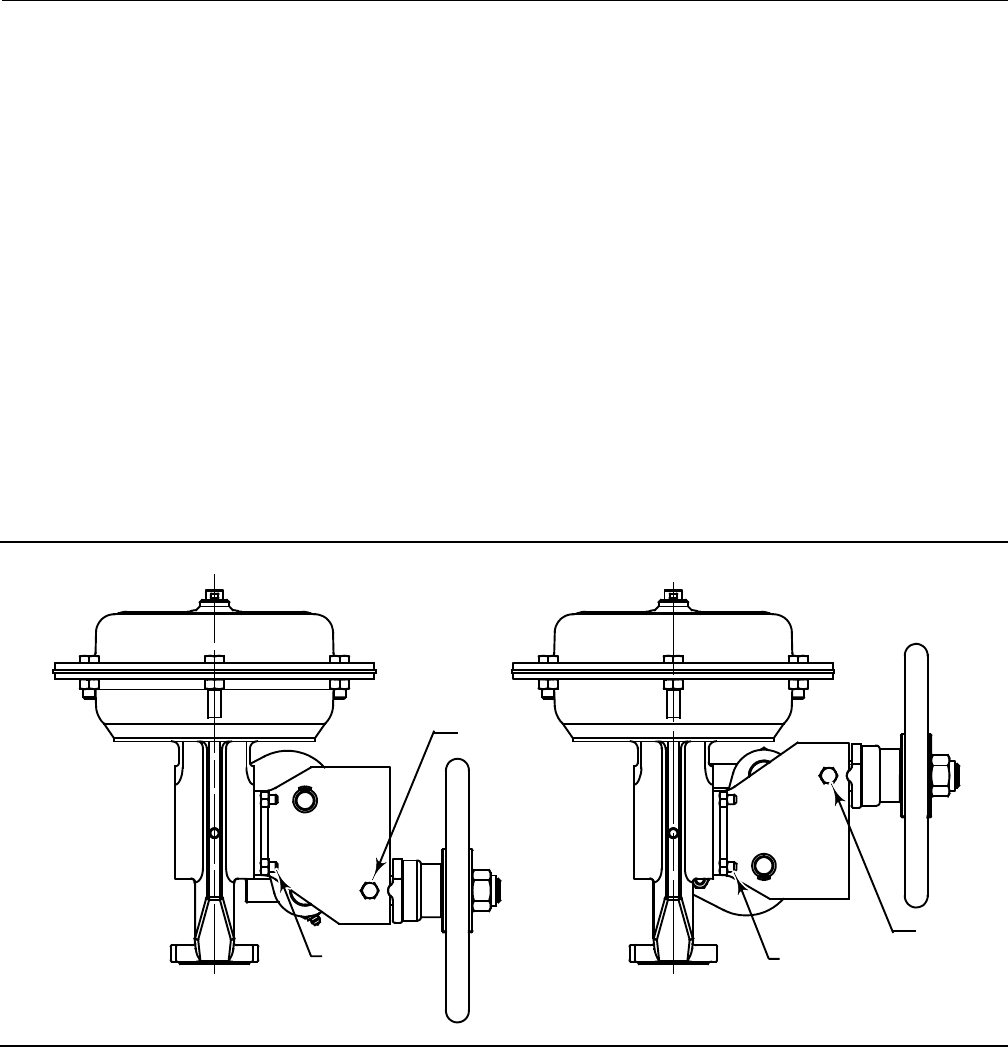
Figure 7. Fisher GX Handwheel Orientation and Grease Zerk Location
AIR-TO-CLOSE, SPRING-TO-OPENAIR-TO-OPEN, SPRING-TO-CLOSE
GE05809-D GE05810-D
APPLY LUBRICANT
Handwheel Operation
CAUTION
This handwheel is designed only for use with size 225 and 750 actuators with 20 mm travel. To avoid equipment damage,
do not assemble this handwheel on size 750 actuators with 40 mm travel or size 1200 actuators.
Principle of Operation
The GX handwheel is designed to compress the actuator springs and override the actuator fail action. Turning the
handwheel drives the screw, nut, and levers. The levers push against the stem connector to transfer this motion.
Reversing the direction of the handwheel will move the nut and levers in the opposite direction. Once the levers are no
longer in contact with the stem connector, the locking screw should be used to secure the handwheel against
undesired movement. To prevent damage due to overtravel, the handwheel should not be turned more than 2 full
turns past the point at which the levers no longer contact the stem connector.
WARNING
To avoid personal injury or loss of process control due to equipment damage, ensure the levers are completely disengaged
and the locking screw is tight while the valve is in normal pneumatic operation.

Instruction Manual
D103175X012
GX Valve and Actuator
August 2011
26
During normal pneumatic operation when the handwheel is not needed, a locking screw (see figure 6) is provided on
the side of the handwheel housing to lock the handwheel levers out of the way.
WARNING
To avoid personal injury or equipment damage due to possible sudden shifting or falling of the valve assembly, do not lift
the valve assembly by the handwheel.
GX Handwheel Installation (for use with 20mm travel only)
1. Note the orientation of the levers to the stem connector for either the air-to-close, spring-to-open configuration or
for the air-to-open, spring-to-close configuration, as shown in figure 7.
2. Adjust the handwheel to allow positioning the levers above the stem connector before installation.
3. Install the handwheel to the GX mounting pad with four studs and nuts, as shown in figure 6. Torque to 24 NSm(18
lbfSft).
4. Apply lithium grease to the grease zerk and to the tip of the levers (where they contact the stem connector), as
showninfigure7.
Travel Stop Operation
Principle of Operation
CAUTION
This travel stop is designed only for use with size 225 and 750 actuators with 20 mm travel. To avoid equipment damage,
do not assemble this travel stop on size 750 actuators with 40 mm travel or size 1200 actuators.
The GX travel stop is designed to mechanically limit and stop the valve at a preset position in an emergency or upon
loss of instrument air. This assembly is mounted on the yoke with four studs. The lever pushes against the stem
connector to stop the travel. Travel position can be adjusted by two adjustable cap screws on the lever, as shown in
figure 8. A cover plate assembly is available to prevent pinch point damage caused by the lever, as shown in figure 8.
WARNING
To avoid personal injury or equipment damage due to possible sudden shifting or falling of the valve assembly, do not lift
the valve assembly by the travel stop.
To avoid personal injury or loss of process control due to equipment damage, screw the adjustable cap screws to ensure the
lever is completely disengaged while the valve is in normal pneumatic operation.
Instruction Manual
D103175X012
GX Valve and Actuator
August 2011
27
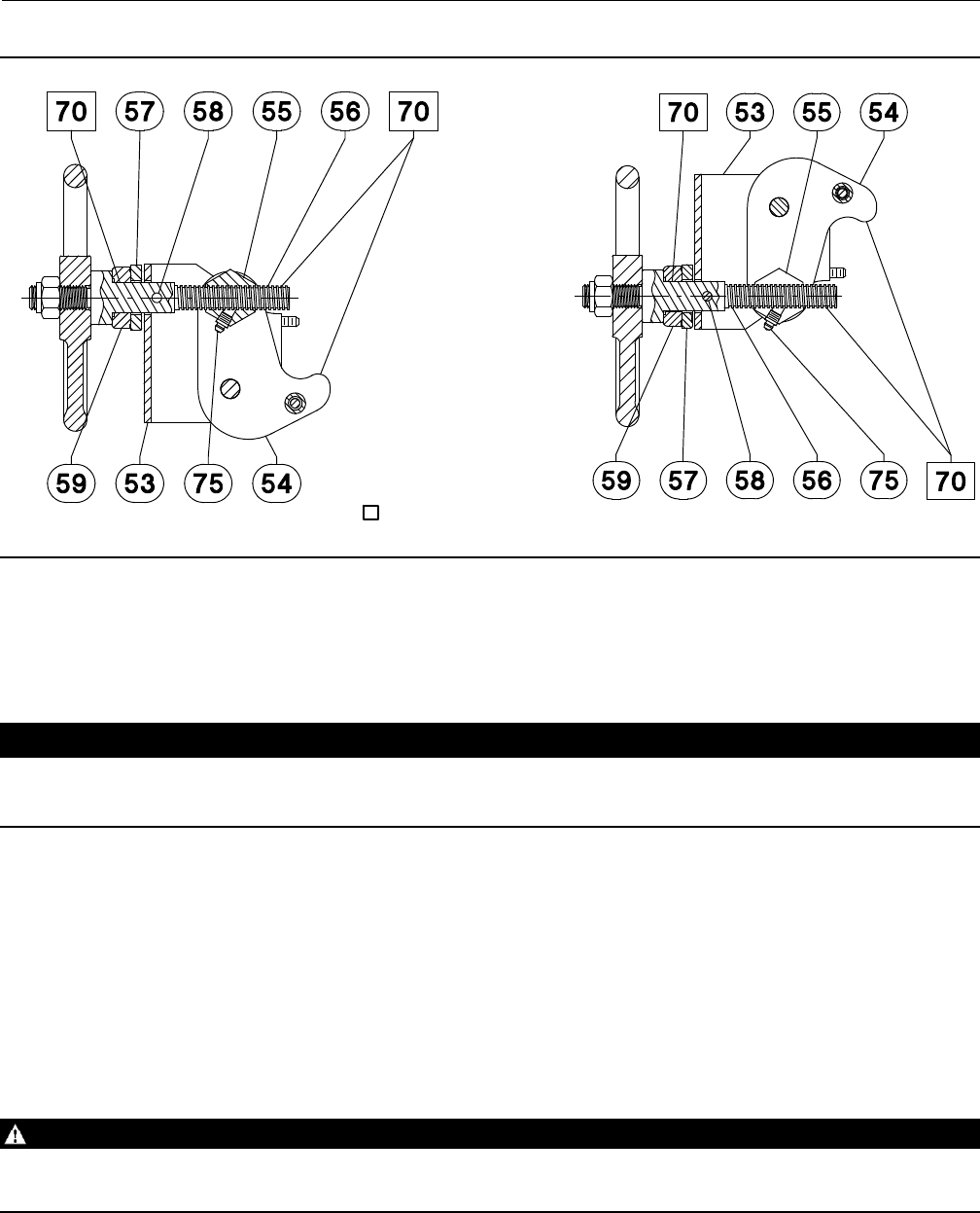
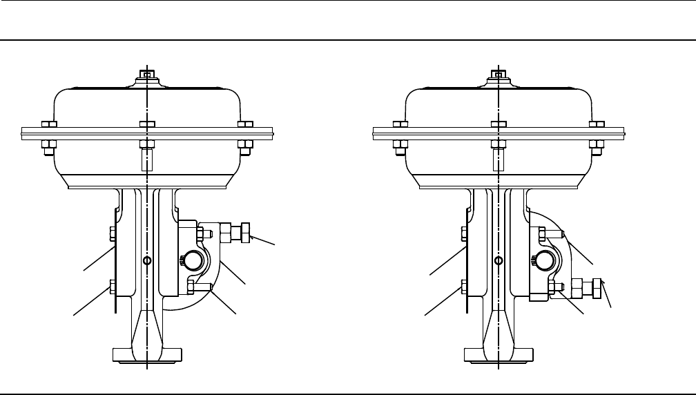
Figure 8. Fisher GX Travel Stop Assembly
COVER PLATE COVER PLATE
CAP SCREW
(4) CAP SCREW (4)
LEVER
LEVER
ADJUSTABLE
CAP SCREW (2)
ADJUSTABLE
CAP SCREW (2)
STUD AND
NUT (4) STUD AND
NUT (4)
DOWNSTOP UPSTOP
GX Travel Stop Installation
Downstop
1. Note the orientation of the lever to the stem connector for downstop positioning, as shown in figure 9. Adjust the
travel stop to allow positioning the lever below the stem connector before installation.
2. Install the travel stop to the GX mounting pad with four studs and nuts, as shown in figure 8. Torque to 24.5 NSm
(18 lbfSft).
3. Apply lithium grease to the tip of the lever (where it contacts the stem connector) and to the two adjustable cap
screws, as shown in figure 9.
Upstop
1. Note the orientation of the lever to the stem connector for upstop positioning, as shown in figure 9. Adjust the
travel stop to allow positioning the lever above the stem connector before installation.
2. Install the travel stop to the GX mounting pad with four studs and nuts, as shown in figure 8. Torque to 24.5 NSm
(18 lbfSft).
3. Apply lithium grease to the tip of the lever (where it contacts the stem connector) and to the two adjustable cap
screws, as shown in figure 9.
Instruction Manual
D103175X012
GX Valve and Actuator
August 2011
28
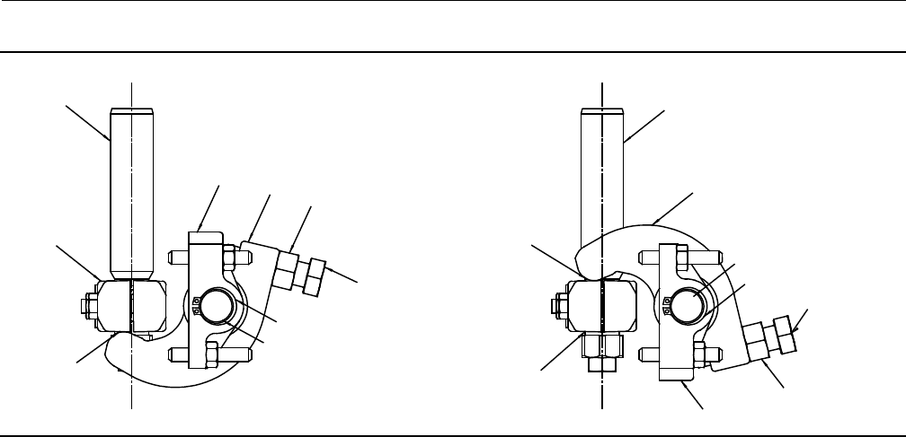
Figure 9. Fisher GX Travel Stop Orientation
ACTUATOR
ROD ACTUATOR
ROD
STEM
CONNECTOR
STEM
CONNECTOR
APPLY
LITHIUM
GREASE TO
LEVERS
APPLY
LITHIUM
GREASE TO
LEVERS
BRACKET
BRACKET
BACK NUT (2)
BACK NUT (2)
LEVER LEVER
SHAFT
SHAFT
RETAINING RING
RETAINING RING
ADJUSTABLE
CAP SCREW (2)
ADJUSTABLE
CAP SCREW (2)
DOWNSTOP UPSTOP
Setting the Travel Stop Position
After sending the required position air signal to the actuator, screw the adjustable cap screws to assure the lever
contacts with the stem connector tightly, then tighten the back nut. Check the actual stem position when giving the
100% air signal.
Standard Accuracy for the travel stop position is +/- 10% for 20 mm travel. For added precision, use the following
procedure.
1. Send the desired position air signal to the actuator.
2. Set the travel stop, screw the adjustable cap screws to assure the lever contacts with the stem connector tightly,
then tighten the back nut.
3. Send a 100% air signal.
4. Measure the difference between the actual stem position and the desired position.
5. Send the air signal for the desired position minus the differential position measured in step 4.
6. Reset the travel stop by adjusting the two cap screws and then tighten the back nut.
Instruction Manual
D103175X012
GX Valve and Actuator
August 2011
29
Figure 10. Fisher GX Balanced Trim
(Standard for DN 80 and 100 [NPS 3 and 4])
GE07161-D APPLY LUBRICANT
Figure 11. Fisher GX Balanced Trim
(DN 150 [NPS 6])
GE17575-C
APPLY LUBRICANT
Figure 12. Fisher GX Unbalanced Port-Guided Trim
(DN 40 to 150 [NPS 1-1/2 to 6])
GE03755_8
Figure 13. Fisher GX Whisper Trim™ III
(DN 150 [NPS 6])
GE23496-A
APPLY LUBRICANT
Instruction Manual
D103175X012
GX Valve and Actuator
August 2011
30
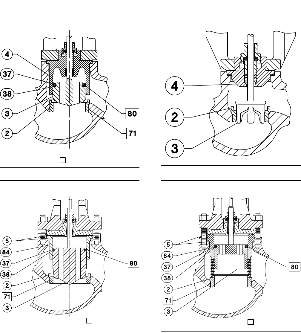
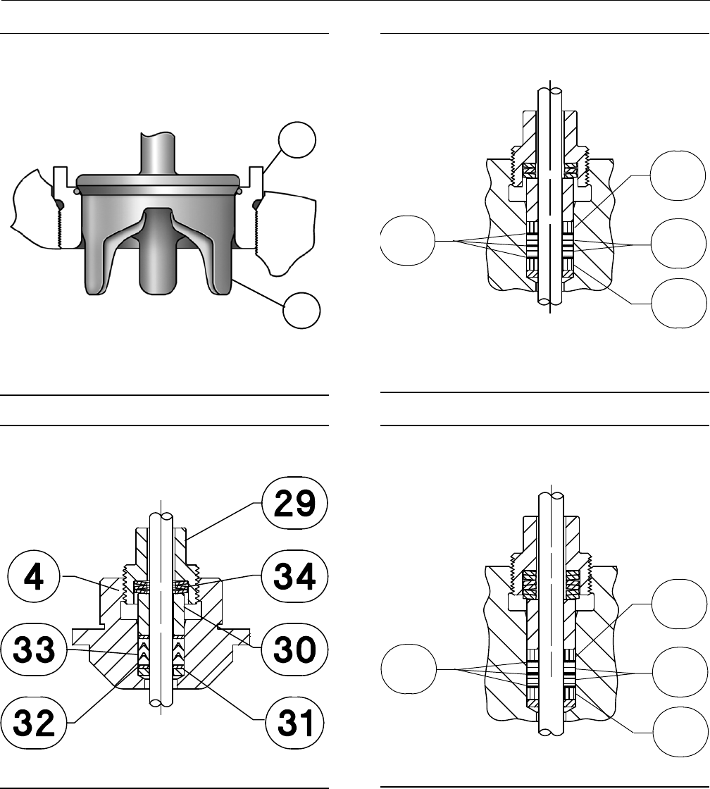
Figure 14. Fisher GX Control Valve with Typical Soft
Seat Trim Construction
(Port Sizes of 36mm - 136mm)
W9023-1
2
3
Figure 15. Fisher GX PTFE Packing
DN15 through DN150 (NPS 1/2 through 6)
GE03755_14
Figure 16. Fisher GX Graphite ULF Packing
DN15 through DN100 (NPS 1/2 through 4)
GE11961_C
43
42
43
44
Figure 17. Fisher GX Graphite ULF Packing
DN150 Only (NPS 6 Only)
GE03755_23
43
42
43
44
Instruction Manual
D103175X012
GX Valve and Actuator
August 2011
31
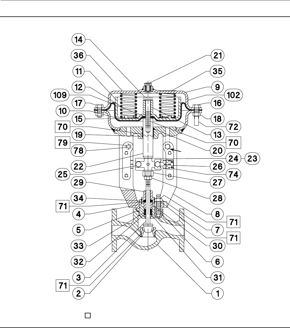
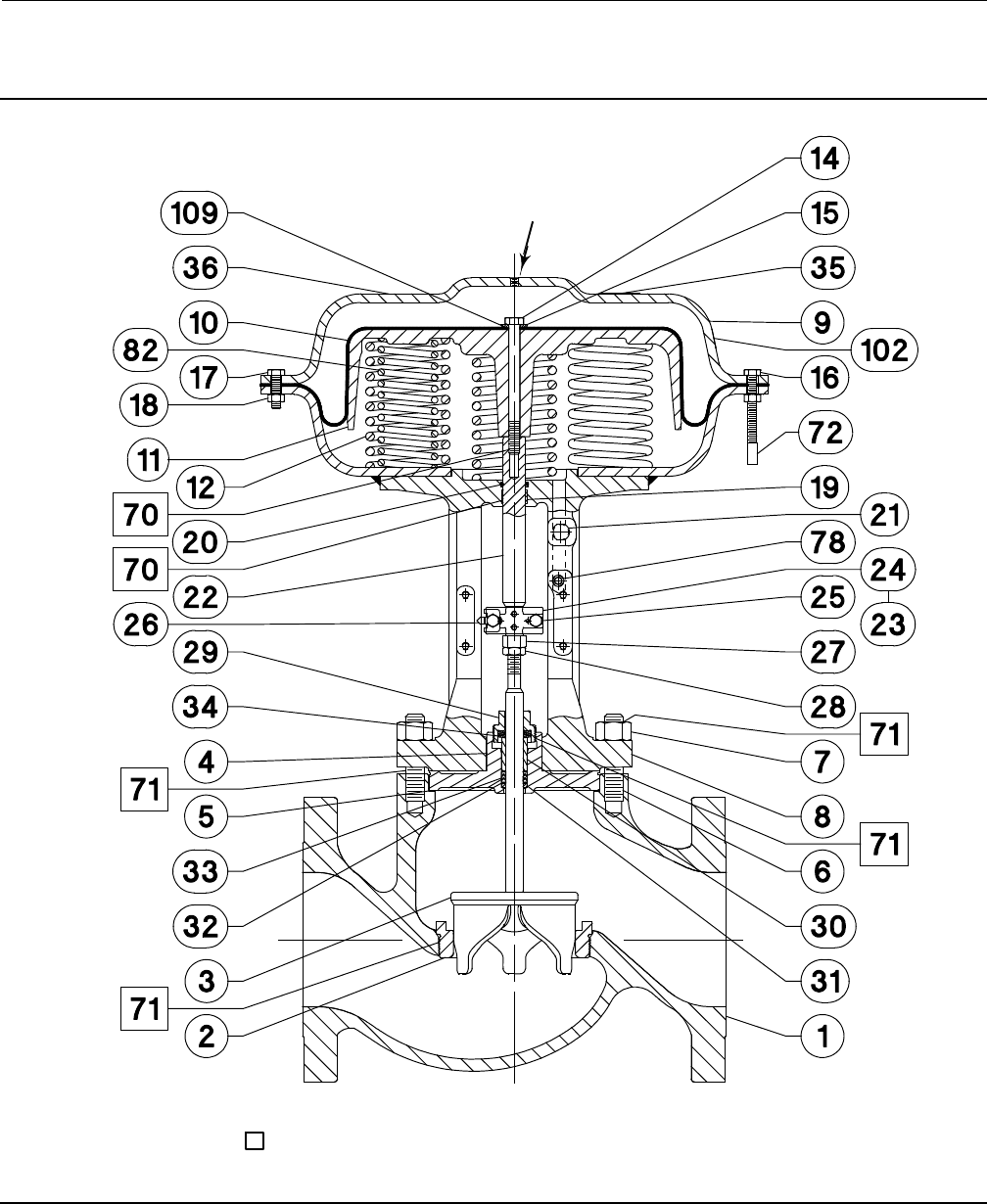
Figure 18. Fisher GX Control Valve and Actuator System Assembly, Air-to-Open (Spring-to-Close) (DN25 (NPS 1) with
Unbalanced Contoured Plug)
GE02171-H
AIR SUPPLY
CONNECTION
APPLY LUBRICANT
Instruction Manual
D103175X012
GX Valve and Actuator
August 2011
32
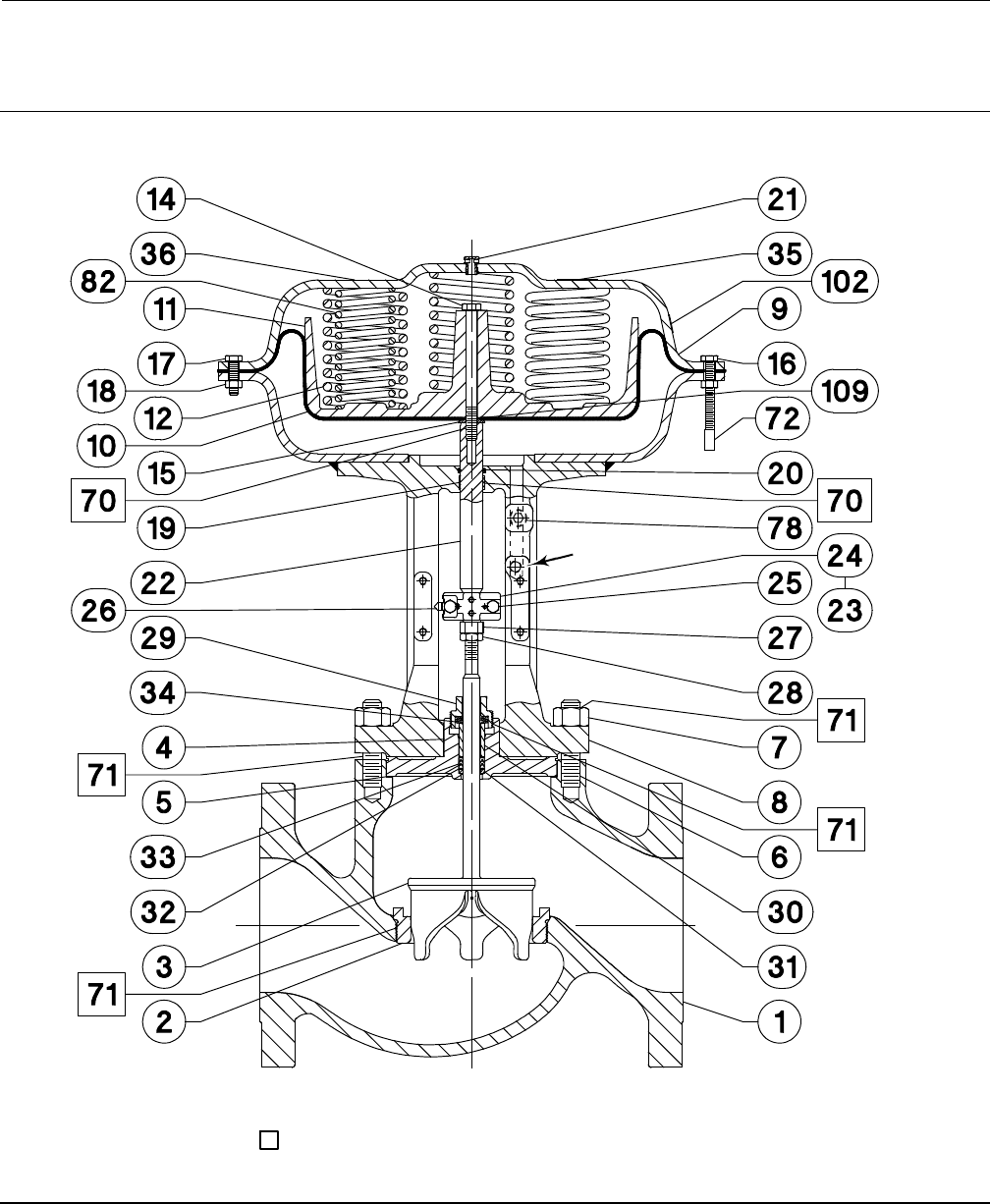
Figure 19. Fisher GX Control Valve and Actuator System Assembly, Air-to-Open (Spring-to-Close) (DN150 (NPS 6)
with Unbalanced Contoured Plug)
GE17517-F
AIR SUPPLY
CONNECTION
APPLY LUBRICANT
Instruction Manual
D103175X012
GX Valve and Actuator
August 2011
33
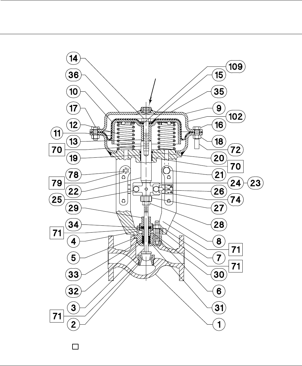
Figure 20. Fisher GX Control Valve and Actuator System Assembly, Air-to-Close (Spring-to-Open) (DN25 (NPS 1) with
Unbalanced Contoured Plug)
GE03515-H
AIR SUPPLY
CONNECTION
APPLY LUBRICANT
Instruction Manual
D103175X012
GX Valve and Actuator
August 2011
34
Figure 21. Fisher GX Control Valve and Actuator System Assembly, Air-to-Close (Spring-to-Open) (DN150 (NPS 6)
with Unbalanced Contoured Plug)
GE23239-D
AIR SUPPLY
CONNECTION
APPLY LUBRICANT
Instruction Manual
D103175X012
GX Valve and Actuator
August 2011
35
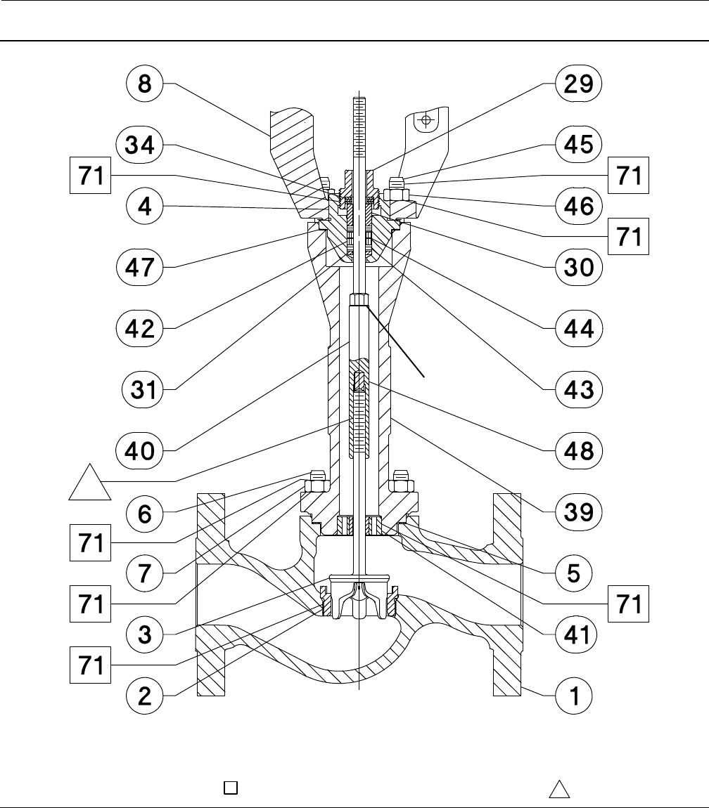
Figure 22. Extension Bonnet with Graphite ULF Packing
GF00337-D
APPLY LUBRICANT
STEM EXTENSION
HEX FLATS
DO NOT APPLY LUBRICANT
Instruction Manual
D103175X012
GX Valve and Actuator
August 2011
36
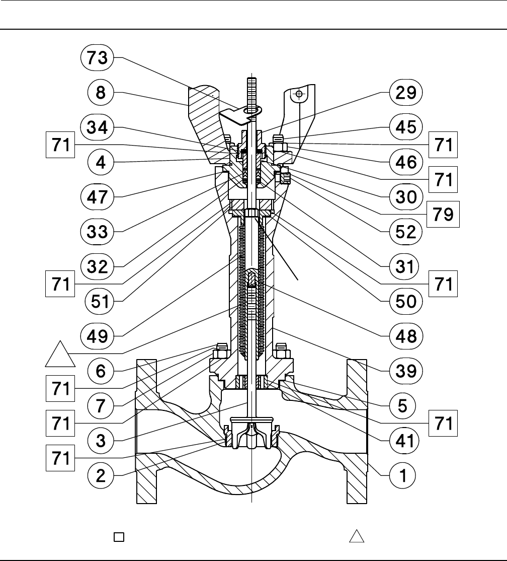
Figure 23. Bellows Extension Bonnet with PTFE Packing
GF00338-D
STEM EXTENSION
HEX FLATS
APPLY LUBRICANT DO NOT APPLY LUBRICANT
Instruction Manual
D103175X012
GX Valve and Actuator
August 2011
37
Figure 24. Cryogenic Extension Bonnet
GE23746-A
APPLY LUBRICANT
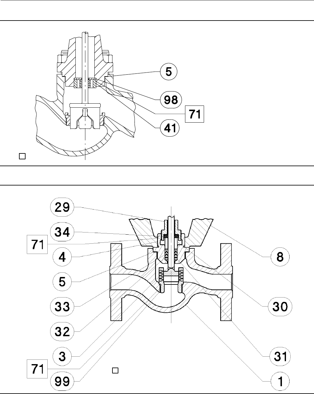
Figure 25. Fisher Cavitrol III Trim, DN25 and DN50 (NPS 1 and NPS 2)
GG03061-2
APPLY LUBRICANT
Instruction Manual
D103175X012
GX Valve and Actuator
August 2011
38
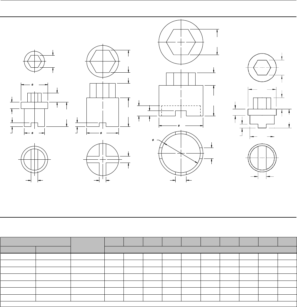
Figure 26. Bellows Nut Removal and Installation Tool
GF00536_3
DN15, 20, 25, 40, and 50
(NPS 1/2, 3/4, 1, 1-1/2, and 2)
DN80 and 100
(NPS 3 and 4)
CHEX
D
B
A
E
HG
F
D
F
E
B
A
6mm 8mm
CHEX
Table 13. Bellows Nut Removal and Installation Tool Dimensions
Valve Size A B C D E FGH
DN NPS mm
15, 20, 25, 40, 50 1/2, 3/4, 1, 1-1/2, 2 125 25 36 20 553 45 3
80, 100 3, 4 135 25 1.42 25 560 --- ---
Instruction Manual
D103175X012
GX Valve and Actuator
August 2011
39
Figure 27. Handwheel Assembly
GE05809_D
APPLY LUBRICANT
Instruction Manual
D103175X012
GX Valve and Actuator
August 2011
40
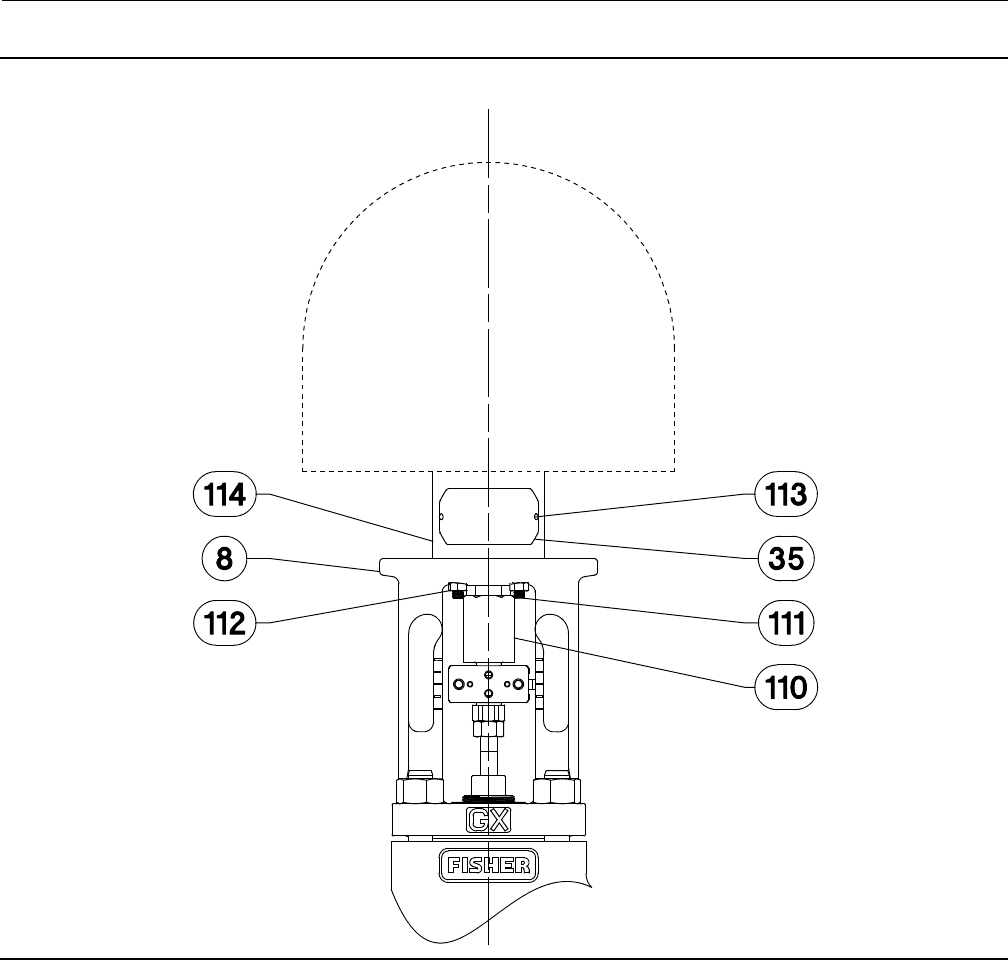
Figure 28. Fisher GX Electric Actuator Mounting
GG12175_A
Instruction Manual
D103175X012
GX Valve and Actuator
August 2011
41
Figure 29. Repair Nameplate (Spaces Provided for Recording Trim Maintenance Data)
GE11233-B
DATE OF MAINTENANCE
PORT DIAMETER
TRIM MATERIAL FLOW
CHARACTERISTIC
FLOW CAPACITY
ACTUATOR ACTION
Parts Ordering
Eachvalveisassignedaserialnumberwhichcanbefoundonthevalveoronthenameplate(figure2andkey35,not
shown). The nameplate will normally be fitted to the actuator. Refer to this serial number when contacting your
Emerson Process Management sales office for technical assistance. When ordering replacement parts refer to this
serial number and give the part description from the following parts list.
WARNING
Use only genuine Fisher replacement parts. Components that are not supplied by Emerson Process Management should
not, under any circumstances, be used in any Fisher valve, because they may void your warranty, might adversely affect the
performance of the valve, and could cause personal injury and property damage.
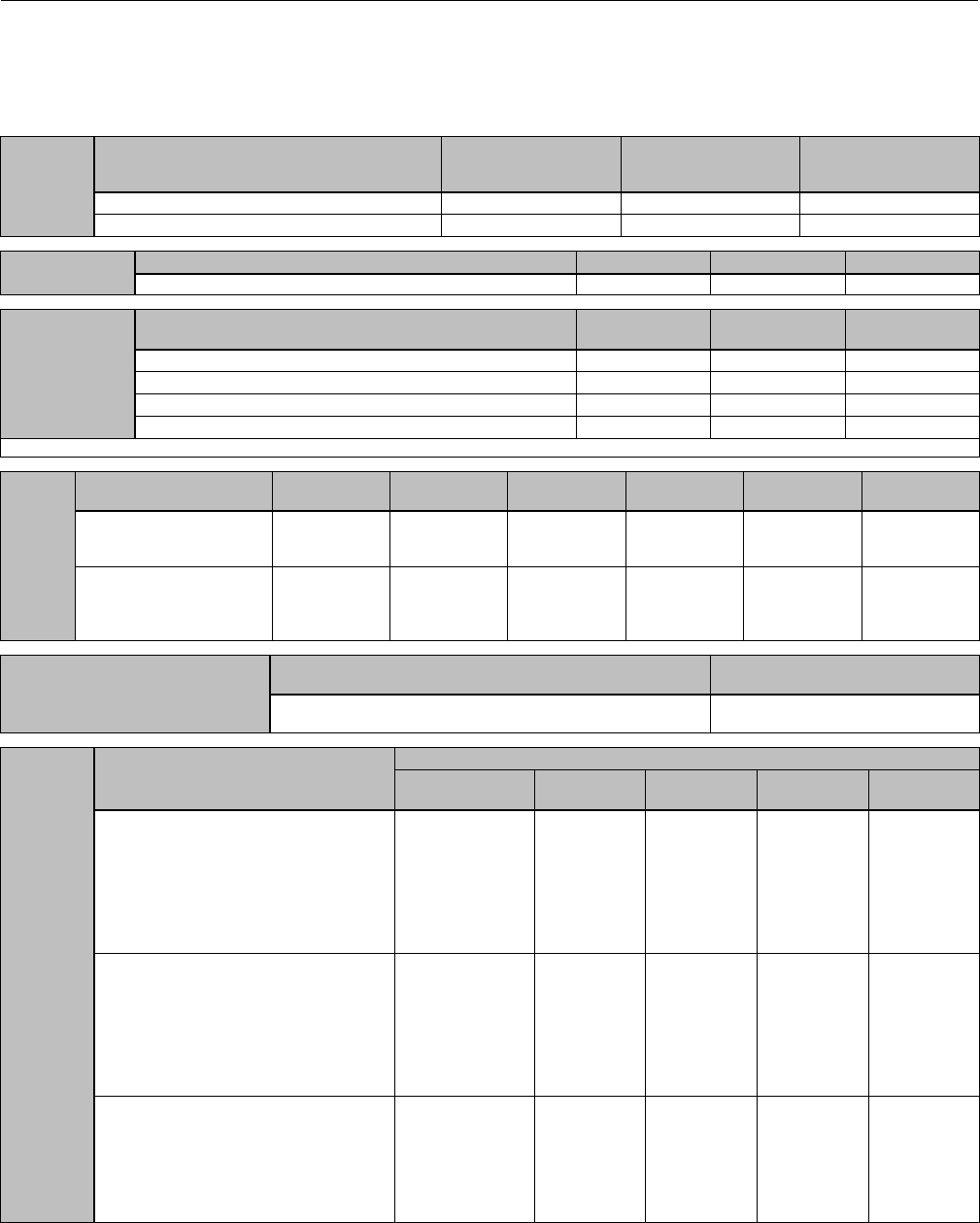
Instruction Manual
D103175X012
GX Valve and Actuator
August 2011
42
Parts Kits
PACKING
KITS
Valve Size
Stem Diameter
DN 25, 40, and 50
(NPS 1, 1-1/2, and 2)
10 mm
DN 80 and 100
(NPS 3 and 4)
14 mm
DN 150
(NPS 6)
19 mm
PTFE packing (Contains keys 32 and 33) RGXPACKX012 RGXPACKX022 RGXPACKX072
Graphite ULF packing (Contains keys 42, 43, and 44) RGXPACKX052 RGXPACKX042 RGXPACKX082
ACTUATOR
KITS
Actuator Size 225 750 1200
Actuator (Contains keys 10, 19, 109, and 20) RGX225X0022 RGX750X0032 RGX1200X042
BALANCED
SEAL KITS(1)
Valve Size DN 80
(NPS 3)
DN 100
(NPS 4)
DN 150
(NPS 6)
Nitrile (Contains keys 37 and 38) RGXSEALX012 RGXSEALX022 RGXSEALX072
Ethylene Propylene (EPDM) (Contains keys 37 and 38) RGXSEALX032 RGXSEALX042 RGXSEALX082
FKM Fluorocarbon (Contains keys 37 and 38) RGXSEALX052 RGXSEALX062 RGXSEALX092
Graphite Piston Ring (Contains key 100) GE26910X012 GE26911X012 GE26912X012
1. A Gasket Kit is required when replacing the seals.
GASKET
KITS
Valve Size DN 25
(NPS 1)
DN 40
(NPS 1-1/2)
DN 50
(NPS 2)
DN 80
(NPS 3)
DN 100
(NPS 4)
DN 150
(NPS 6)
Body / Bonnet Gasket Kit
(Graphite Laminate)
(Contains key 5)
GE00077X012 GE00078X012 GE00079X012 GE00080X012 GE00052X012 RGASKETXA62
Body / Bonnet Gasket and
Extension Bonnet Gasket Kit
(Graphite Laminate)
(Contains keys 5 and 47)
RGASKETXA12 RGASKETXA22 RGASKETXA32 RGASKETXA42 RGASKETXA52 ---
REPAIR NAMEPLATE
Description DN15 to 150
(NPS 1/2 to 6)
18-8 stainless steel nameplate. Will mount to all GX actuator sizes
using casing bolt. See figure 29. GE11233X012
BELLOWS
KITS
Description
Valve Size
DN15, 20, 25 (NPS
1/2, 3/4, 1)
DN40
(NPS 1-1/2)
DN50
(NPS 2)
DN80
(NPS 3)
DN100
(NPS 4)
1.4571 (316Ti) bellows with S31603
extension stem (key 49), graphite laminate
body/bonnet gasket (key 5), graphite
laminate extension bonnet gasket (key 47),
graphite laminate bellows gasket (key 50),
S31603 extension stem insert (key 48),
anti-extrusion washer (key 32 - quantity of 2);
PTFE packing set (key 33)
RGXBELLX012 RGXBELLX042 RGXBELLX072 RGXBELLX102 RGXBELLX132
N10276 bellows with S31603 extension stem
(key 49), graphite laminate body/bonnet
gasket (key 5), graphite laminate extension
bonnet gasket (key 47), graphite laminate
bellows gasket (key 50), S31603 extension
stem insert (key 48), anti-extrusion washer
(key 32 - quantity of 2); PTFE packing set (key
33)
RGXBELLX022 RGXBELLX052 RGXBELLX082 RGXBELLX112 RGXBELLX142
N10276 bellows with N06022 extension stem
(key 49), PTFE / N10276 body/bonnet gasket
(key 5), PTFE / N10276 extension bonnet
gasket (key 47), PTFE / N10276 bellows
gasket (key 50), N10276 extension stem
insert (key 48), anti-extrusion washer (key 32
- quantity of 2); PTFE packing set (key 33)
RGXBELLX032 RGXBELLX062 RGXBELLX092 RGXBELLX122 RGXBELLX152

Instruction Manual
D103175X012
GX Valve and Actuator
August 2011
43
Parts List
Note
For part numbers not shown, contact your Emerson Process
Management sales office.
Key Description Part Number
1ValveBody
2* Seat Ring see following table
3* Valve Plug/Stem see following table
4 Bonnet
5* Body/Bonnet Gasket, graphite laminate see gasket kits table
6 Body/Bonnet Bolting (4 req'd)
7 Body/Bonnet Nut (4 req'd)
8ActuatorYoke
9 Upper Diaphragm Casing
10* Diaphragm
11 Diaphragm Plate
12 Actuator Springs
13 Actuator Spacer
14 Cap Screw
15 Washer
16 CapScrew,long
Size 225 Actuator (2 req'd)
Size 750 Actuator (2 req'd)
Size 1200 Actuator (4 req'd)
17 Cap Screw, short
Size 225 Actuator (4 req'd)
Size 750 Actuator (8 req'd)
Size 1200 Actuator (12 req'd)
18 Hex Nut
Size 225 Actuator (6 req'd)
Size 750 Actuator (10 req'd)
Size 1200 Actuator (16 req'd)
19* Actuator Rod Bushing
20* Actuator Rod Seal
21 Vent Cap
22 Actuator Rod
23 Stem Connector Nut Half
24 Stem Connector Bolt Half
25 Cap Screw (2 req'd)
26 Travel Indicator
27 Stem Adjustor Nut
28 Locknut
29 Packing Follower
30 Packing Spacer
31 Packing Box Ring
32* Anti-Extrusion Washer (2 req'd)
33* PTFE Packing Set
34 Belleville Spring (3 req'd)
Key Description
35 Nameplate
36 Warning Tag
37* Seal Ring
38* Backup Ring
39 Extension Bonnet
40 Stem Extension
41 Extension Bonnet Lower Bushing
42* Graphite ULF Packing Ring (2 req'd)
43* Packing Ring (2 req'd)
44* Packing Washer (3 req'd)
45 Yoke/Extension Bonnet Bolting (4 req'd)
46 Yoke/Extension Bonnet Nut (4 req'd)
47* Extension Bonnet Gasket
48* Insert (req'd for assembly of valve stem to extension stem)
49* Bellows/Stem Assembly
50* Bellows Gasket
51 Bellows Nut
52 Pipe Plug
53 Handjack Body
54 Lever
55 Operating Nut
56 Drive Screw
57 Pivot Washer
58 Grooved Pin
59 Bearing
60 Pivot Pin
61 Bushing
62 Retainer Ring
63 Spacer
64 Cap Screw
65 Hex Nut
66 Lock Screw
67 Hex Nut
68 Stud
69 Hex Nut
70 Lubricant, Lithium Grease
71 Lubricant, Anti-Seize
72 Cap Plug
73 Warning Tag
74 Travel Indicator Scale
75 Zerk Fitting
76 Handwheel
77 Locknut
78 Pipe Plug
79 Anti-seize sealant
80 Lubricant, silicone sealant
81 Pipe Plug
82 Inner Actuator Spring
84 Guide Sleeve or Cage
98 Low Temp Bushing
99 Cavitrol III cage
100 Piston Ring
109* O-ring
110 Rod Adaptor
111 Stud
112 Nut
113 Drive Screw
114 Electric Actuator Spacer
115 Lead Seal and Wire (not shown)
*Recommended spare parts
See Parts Kits
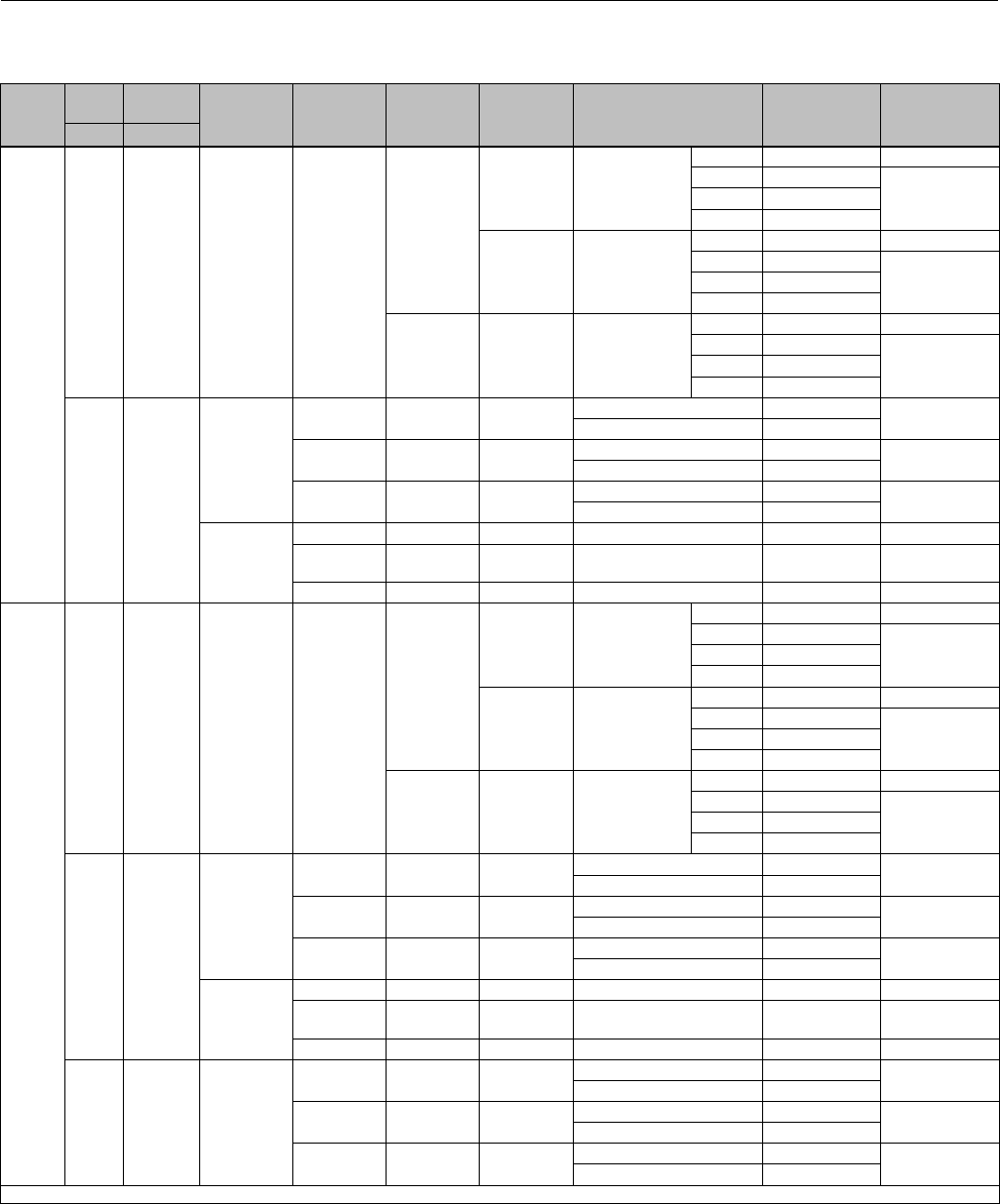
Instruction Manual
D103175X012
GX Valve and Actuator
August 2011
44
Key 3 Valve Plug/Stem and Key 2 Seat Ring (Plain Bonnet, LCC, WCC/1.0619 and CF3M/1.4409 Valve Body Material)
VALVE
SIZE
PORT
SIZE TRAVEL PLUG STYLE
VALVE
PLUG
MATERIAL
STEM
MATERIAL
SEAT RING
MATERIAL TRIM STYLE
VALVE
PLUG/STEM
PART NUMBER
SEAT RING
PART NUMBER
mm mm
DN15
(NPS
1/2)
4.8 20 Unbalanced R31233
S31603
CF3M Micro-Flow Flat
1_8' GE04253X032 (1)
2_15' GE04255X032
GE04252X012
4_39' GE04256X032
9_30' GE13780X012
S31603/
CoCr-A Seat Micro-Flow Flat
1_8' GE04253X112 (1)
2_15' GE04255X032
GE04252X052
4_39' GE04256X032
9_30' GE13780X012
N06022 CW2M Micro-Flow Flat
1_8' GE04253X072 (1)
2_15' GE04255X072
GE04252X042
4_39' GE04256X072
9_30' GE13780X032
9.5 20
Unbalanced
(Standard)
S31603 S31603 CF3M Equal Percentage GE03891X012 GE00051X012
Linear GE03893X012
S31603/
CoCr-A Seat S20910 SST CF3M/
CoCr-A Seat
Equal Percentage GE03891X022 GE00051X062
Linear GE03893X022
N06022 N06022 CW2M Equal Percentage GE03891X052 GE00051X052
Linear GE03893X052
Unbalanced
(Reduced
Capacity)
S31603 S31603 CF3M Equal Percentage GE08919X012 GE00051X012
S31603/
CoCr-A Seat S20910 SST CF3M/
CoCr-A Seat Equal Percentage GE08919X022 GE00051X062
N06022 N06022 CW2M Equal Percentage GE08919X052 GE00051X052
DN20
(NPS
3/4)
4.8 20 Unbalanced R31233
S31603
CF3M Micro-Flow Flat
1_8' GE04253X032 (1)
2_15' GE04255X032
GE04252X012
4_39' GE04256X032
9_30' GE13780X012
S31603/
CoCr-A Seat Micro-Flow Flat
1_8' GE04253X112 (1)
2_15' GE04255X032
GE04252X052
4_39' GE04256X032
9_30' GE13780X012
N06022 CW2M Micro-Flow Flat
1_8' GE04253X072 (1)
2_15' GE04255X072
GE04252X042
4_39' GE04256X072
9_30' GE13780X032
9.5 20
Unbalanced
(Standard)
S31603 S31603 CF3M Equal Percentage GE03891X012 GE00051X012
Linear GE03893X012
S31603/
CoCr-A Seat S20910 SST CF3M/
CoCr-A Seat
Equal Percentage GE03891X022 GE00051X062
Linear GE03893X022
N06022 N06022 CW2M Equal Percentage GE03891X052 GE00051X052
Linear GE03893X052
Unbalanced
(Reduced
Capacity)
S31603 S31603 CF3M Equal Percentage GE08919X012 GE00051X012
S31603/
CoCr-A Seat S20910 SST CF3M/
CoCr-A Seat Equal Percentage GE08919X022 GE00051X062
N06022 N06022 CW2M Equal Percentage GE08919X052 GE00051X052
14 20 Unbalanced
S31603 S31603 CF3M Equal Percentage GE03890X012 GE00049X012
Linear GE03892X012
S31603/
CoCr-A Seat S20910 SST CF3M/
CoCr-A Seat
Equal Percentage GE03890X022 GE00049X062
Linear GE03892X022
N06022 N06022 CW2M Equal Percentage GE03890X052 GE00049X052
Linear GE03892X052
1. The seat ring is included in the Valve Plug / Stem Part Number.
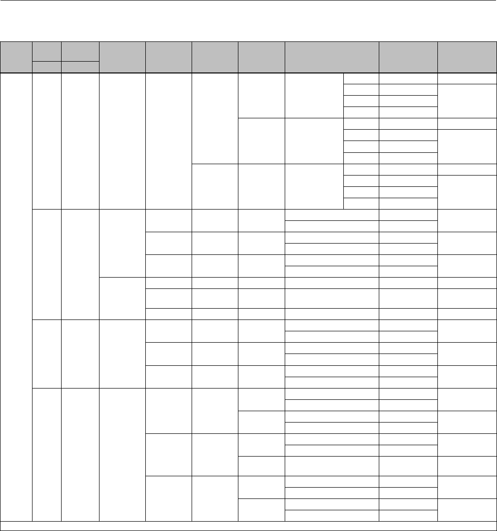
Instruction Manual
D103175X012
GX Valve and Actuator
August 2011
45
Key 3 Valve Plug/Stem and Key 2 Seat Ring (Plain Bonnet, LCC, WCC/1.0619 and CF3M/1.4409 Valve Body Material)
VALVE
SIZE
PORT
SIZE TRAVEL PLUG STYLE
VALVE
PLUG
MATERIAL
STEM
MATERIAL
SEAT RING
MATERIAL TRIM STYLE
VALVE
PLUG/STEM
PART NUMBER
SEAT RING
PART NUMBER
mm mm
DN25
(NPS 1)
4.8 20 Unbalanced R31233
S31603
CF3M Micro-Flow Flat
1_8' GE04253X032 (1)
2_15' GE04255X032
GE04252X012
4_39' GE04256X032
9_30' GE13780X012
S31603/
CoCr-A Seat Micro-Flow Flat
1_8' GE04253X112 (1)
2_15' GE04255X032
GE04252X052
4_39' GE04256X032
9_30' GE13780X012
N06022 CW2M Micro-Flow Flat
1_8' GE04253X072 (1)
2_15' GE04255X072
GE04252X042
4_39' GE04256X072
9_30' GE13780X032
9.5 20
Unbalanced
(Standard)
S31603 S31603 CF3M Equal Percentage GE03891X012 GE00051X012
Linear GE03893X012
S31603/
CoCr-A Seat S20910 SST CF3M/
CoCr-A Seat
Equal Percentage GE03891X022 GE00051X062
Linear GE03893X022
N06022 N06022 CW2M Equal Percentage GE03891X052 GE00051X052
Linear GE03893X052
Unbalanced
(Reduced
Capacity)
S31603 S31603 CF3M Equal Percentage GE08919X012 GE00051X012
S31603/
CoCr-A Seat S20910 SST CF3M/
CoCr-A Seat Equal Percentage GE08919X022 GE00051X062
N06022 N06022 CW2M Equal Percentage GE08919X052 GE00051X052
14 20 Unbalanced
S31603 S31603 CF3M Equal Percentage GE03890X012 GE00049X012
Linear GE03892X012
S31603/
CoCr-A Seat S20910 SST CF3M/
CoCr-A Seat
Equal Percentage GE03890X022 GE00049X062
Linear GE03892X022
N06022 N06022 CW2M Equal Percentage GE03890X052 GE00049X052
Linear GE03892X052
22 20 Unbalanced
S31603 S31603
CF3M Equal Percentage GE00081X012 GE00047X012
Linear GE00082X012
CF3M/
PTFE Seat
Equal Percentage GE00081X012 GE05240X012
Linear GE00082X012
S31603/
CoCr-A Seat S20910 SST
CF3M/
CoCr-A Seat
Equal Percentage GE00081X022 GE00047X062
Linear GE00082X022
S17400
Cage Cavitrol III Trim GG00409X012 GE35685X012
N06022 N06022
CW2M Equal Percentage GE00081X052 GE00047X052
Linear GE00082X052
CW2M/
PTFE Seat
Equal Percentage GE00081X052 GE05240X042
Linear GE00082X052
1. The seat ring is included in the Valve Plug / Stem Part Number.

Instruction Manual
D103175X012
GX Valve and Actuator
August 2011
46
Key 3 Valve Plug/Stem and Key 2 Seat Ring (Plain Bonnet, LCC, WCC/1.0619 and CF3M/1.4409 Valve Body Material)
VALVE
SIZE
PORT
SIZE TRAVEL PLUG STYLE
VALVE
PLUG
MATERIAL
STEM
MATERIAL
SEAT RING
MATERIAL TRIM STYLE
VALVE
PLUG/STEM
PART NUMBER
SEAT RING
PART NUMBER
mm mm
DN40
(NPS
1-1/2)
14 20 Unbalanced
S31603 S31603 CF3M Equal Percentage GE03890X012 GE00057X012
Linear GE03892X012
S31603/
CoCr-A Seat S20910 SST CF3M/
CoCr-A Seat
Equal Percentage GE03890X022 GE00057X062
Linear GE03892X022
N06022 N06022 CW2M Equal Percentage GE03890X052 GE00057X052
Linear GE03892X052
22 20 Unbalanced
S31603 S31603
CF3M Equal Percentage GE00081X012 GE00055X012
Linear GE00082X012
CF3M/
PTFE Seat
Equal Percentage GE00081X012 GE05240X052
Linear GE00082X012
S31603/
CoCr-A Seat S20910 SST CF3M/
CoCr-A Seat
Equal Percentage GE00081X022 GE00055X062
Linear GE00082X022
N06022 N06022
CW2M Equal Percentage GE00081X052 GE00055X052
Linear GE00082X052
CW2M/
PTFE Seat
Equal Percentage GE00081X052 GE05240X082
Linear GE00082X052
36 20 Unbalanced
CF3M S31603
CF3M Equal Percentage GE00083X012 GE12607X012
Linear GE00084X012
CF3M/
PTFE Seat
Equal Percentage GE00083X012 GE12745X012
Linear GE00084X012
CF3M/
CoCr-A Seat S20910 SST
CF3M/
CoCr-A Seat
and Guide
Equal Percentage GE00083X022
GE00053X062
Linear GE00084X022
S17400
Cage Cavitrol III Trim GG00410X012 GE35686X012
CF3M
Nitride S31603
CF3M Equal Percentage GE00083X092 GE12607X012
Linear GE00084X082
CF3M/PTFE
Seat
Equal Percentage GE00083X092 GE12745X012
Linear GE00084X082
CF3M/CoCr-
ASeatand
Guide
Equal Percentage GE00083X092
GE00053X062
Linear GE00084X082
CW2M N06022
CW2M Equal Percentage GE00083X072 GE12607X032
Linear GE00084X072
CW2M/
PTFE Seat
Equal Percentage GE00083X072 GE12745X102
Linear GE00084X072
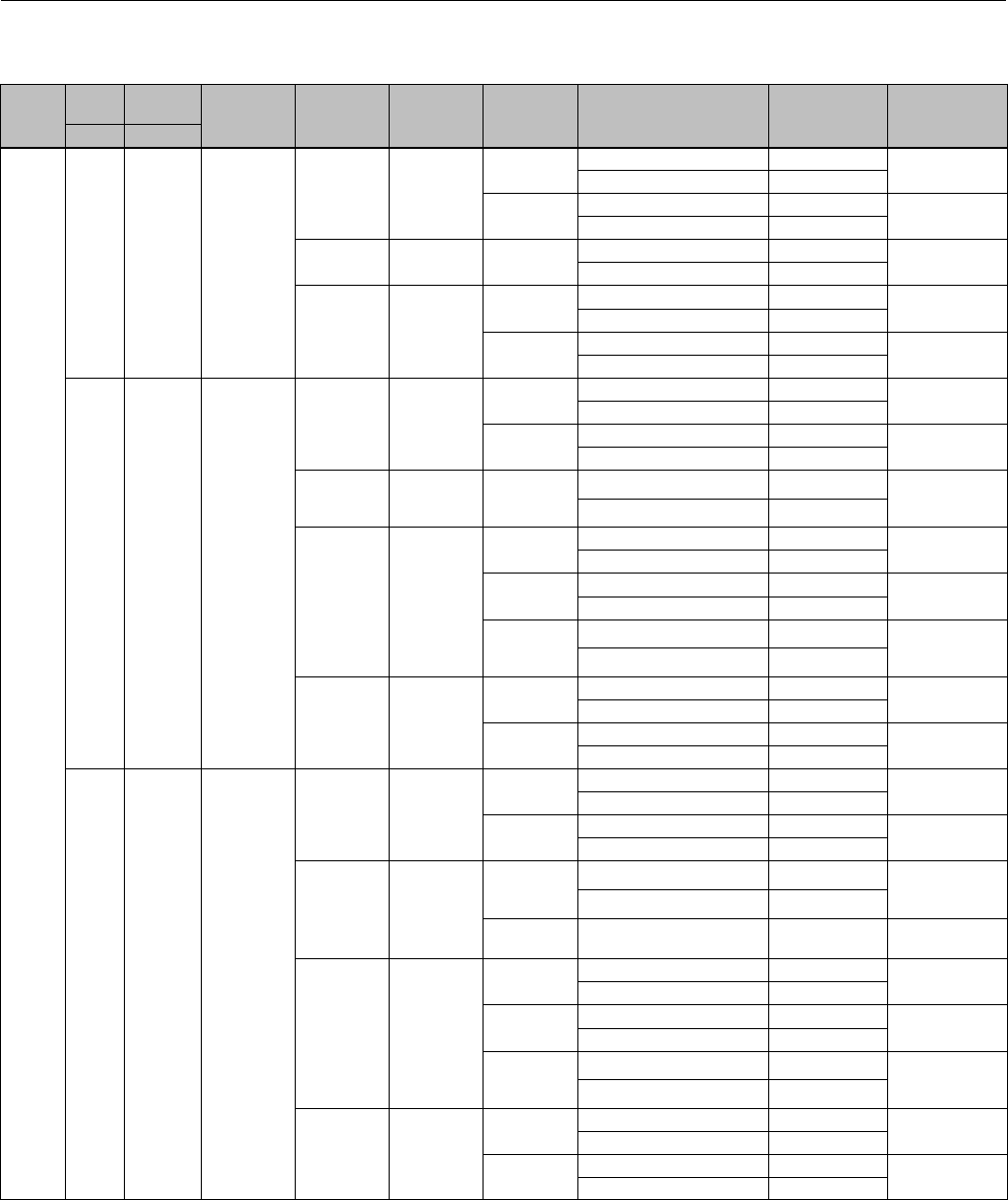
Instruction Manual
D103175X012
GX Valve and Actuator
August 2011
47
Key 3 Valve Plug/Stem and Key 2 Seat Ring (Plain Bonnet, LCC, WCC/1.0619 and CF3M/1.4409 Valve Body Material)
VALVE
SIZE
PORT
SIZE TRAVEL PLUG STYLE
VALVE
PLUG
MATERIAL
STEM
MATERIAL
SEAT RING
MATERIAL TRIM STYLE
VALVE
PLUG/STEM
PART NUMBER
SEAT RING
PART NUMBER
mm mm
DN50
(NPS 2)
22 20 Unbalanced
S31603 S31603
CF3M Equal Percentage GE00081X012 GE00063X012
Linear GE00082X012
CF3M/
PTFE Seat
Equal Percentage GE00081X012 GE05240X092
Linear GE00082X012
S31603/
CoCr-A Seat S20910 SST CF3M/
CoCr-A Seat
Equal Percentage GE00081X022 GE00063X062
Linear GE00082X022
N06022 N06022
CW2M Equal Percentage GE00081X052 GE00063X052
Linear GE00082X052
CW2M/
PTFE Seat
Equal Percentage GE00081X052 GE05240X122
Linear GE00082X052
36 20 Unbalanced
CF3M S31603
CF3M Equal Percentage GE00083X012 GE12609X012
Linear GE00084X012
CF3M/
PTFE Seat
Equal Percentage GE00083X012 GE12745X022
Linear GE00084X012
CF3M/
CoCr-A Seat S20910 SST
CF3M/
CoCr-A Seat
and Guide
Equal Percentage GE00083X022
GE00061X062
Linear GE00084X022
CF3M
Nitride S31603
CF3M Equal Percentage GE00083X092 GE12609X012
Linear GE00084X082
CF3M/PTFE
Seat
Equal Percentage GE00083X092 GE12745X022
Linear GE00084X082
CF3M/CoCr-
ASeatand
Guide
Equal Percentage GE00083X092
GE00061X062
Linear GE00084X082
CW2M N06022
CW2M Equal Percentage GE00083X072 GE12609X032
Linear GE00084X072
CW2M/
PTFE Seat
Equal Percentage GE00083X072 GE12745X112
Linear GE00084X072
46 20 Unbalanced
CF3M S31603
CF3M Equal Percentage GE00085X012 GE12608X012
Linear GE00086X012
CF3M/
PTFE Seat
Equal Percentage GE00085X012 GE12745X032
Linear GE00086X012
CF3M/
CoCr-A Seat S20910 SST
CF3M/
CoCr-A Seat
and Guide
Equal Percentage GE00085X022
GE00059X062
Linear GE00086X022
S17400
Cage Cavitrol III Trim GG00414X012 GE35687X012
CF3M
Nitride S31603
CF3M Equal Percentage GE00085X092 GE12608X012
Linear GE00086X082
CF3M/PTFE
Seat
Equal Percentage GE00085X092 GE12745X032
Linear GE00086X082
CF3M/CoCr-
ASeatand
Guide
Equal Percentage GE00085X092
GE00059X062
Linear GE00086X082
CW2M N06022
CW2M Equal Percentage GE00085X072 GE12608X032
Linear GE00086X072
CW2M/
PTFE Seat
Equal Percentage GE00085X072 GE12745X122
Linear GE00086X072

Instruction Manual
D103175X012
GX Valve and Actuator
August 2011
48
Key 3 Valve Plug/Stem and Key 2 Seat Ring (Plain Bonnet, LCC, WCC/1.0619 and CF3M/1.4409 Valve Body Material)
VALVE
SIZE
PORT
SIZE TRAVEL PLUG STYLE VALVE PLUG
MATERIAL
STEM
MATERIAL
SEAT RING
MATERIAL TRIM STYLE
VALVE
PLUG/STEM PART
NUMBER
SEAT RING PART
NUMBER
mm mm
DN80
(NPS 3)
36 20 Unbalanced
CF3M S31603
CF3M Equal Percentage GE00097X012 GE12612X012
Linear GE00098X012
CF3M/
PTFE Seat
Equal Percentage GE00097X012 GE12745X042
Linear GE00098X012
CF3M/
CoCr-A Seat S20910 SST
CF3M/
CoCr-A Seat
and Guide
Equal Percentage GE00097X022
GE00069X062
Linear GE00098X022
CF3M Nitride S31603
CF3M Equal Percentage GE00097X092 GE12612X012
Linear GE00098X082
CF3M/PTFE
Seat
Equal Percentage GE00097X092 GE12745X042
Linear GE00098X082
CF3M/CoCr-
ASeatand
Guide
Equal Percentage GE00097X092
GE00069X062
Linear GE00098X082
CW2M N06022
CW2M Equal Percentage GE00097X072 GE12612X032
Linear GE00098X072
CW2M/
PTFE Seat
Equal Percentage GE00097X072 GE12745X132
Linear GE00098X072
46 20 Unbalanced
CF3M S31603
CF3M Equal Percentage GE00095X012 GE12611X012
Linear GE00096X012
CF3M/
PTFE Seat
Equal Percentage GE00095X012 GE12745X052
Linear GE00096X012
CF3M/
CoCr-A Seat S20910 SST
CF3M/
CoCr-A Seat
and Guide
Equal Percentage GE00095X022
GE00067X062
Linear GE00096X022
CF3M Nitride S31603
CF3M Equal Percentage GE00095X092 GE12611X012
Linear GE00096X082
CF3M/PTFE
Seat
Equal Percentage GE00095X092 GE12745X052
Linear GE00096X082
CF3M/CoCr-
ASeatand
Guide
Equal Percentage GE00095X092
GE00067X062
Linear GE00096X082
CW2M N06022
CW2M Equal Percentage GE00095X072 GE12611X032
Linear GE00096X072
CW2M/
PTFE Seat
Equal Percentage GE00095X072 GE12745X142
Linear GE00096X072
70 40 Unbalanced
CF3M S31603
CF3M Equal Percentage GE00093X012 GE12610X012
Linear GE00094X012
CF3M/
PTFE Seat
Equal Percentage GE00093X012 GE12745X062
Linear GE00094X012
CF3M/
CoCr-A Seat S20910 SST
CF3M/
CoCr-A Seat
and Guide
Equal Percentage GE00093X022 GE00065X062
Linear GE00094X022
Whisper Trim III GE20152X012 GE00065X062
CF3M Nitride S31603
CF3M Equal Percentage GE00093X092 GE12610X012
Linear GE00094X092
CF3M/PTFE
Seat
Equal Percentage GE00093X092 GE12745X062
Linear GE00094X092
CF3M/CoCr-
ASeatand
Guide
Equal Percentage GE00093X092
GE00065X062
Linear GE00094X092
CW2M N06022
CW2M Equal Percentage GE00093X072 GE12610X032
Linear GE00094X072
CW2M/
PTFE Seat
Equal Percentage GE00093X072 GE12745X152
Linear GE00094X072

Instruction Manual
D103175X012
GX Valve and Actuator
August 2011
49
Key 3 Valve Plug/Stem and Key 2 Seat Ring (Plain Bonnet, LCC, WCC/1.0619 and CF3M/1.4409 Valve Body Material)
VALVE
SIZE
PORT
SIZE TRAVEL PLUG STYLE
VALVE
PLUG
MATERIAL
STEM
MATERIAL
SEAT RING
MATERIAL TRIM STYLE
VALVE
PLUG/STEM
PART NUMBER
SEAT RING
PART NUMBER
mm mm
DN80
(NPS 3) 70 20 Balanced
S31603 S31603 CF3M Equal Percentage GE00087X012 GE12610X012
Linear GE00088X012
S31603/
CoCr-A Seat S20910 SST
CF3M/
CoCr-A Seat
and Guide
Equal Percentage GE00087X022
GE00065X062
Linear GE00088X022
N06022 N06022 CW2M Equal Percentage GE00087X062 GE12610X032
Linear GE00088X062
DN100
(NPS 4)
46 20 Unbalanced
CF3M S31603
CF3M Equal Percentage GE01114X012 GE12615X012
Linear GE01115X012
CF3M/
PTFE Seat
Equal Percentage GE01114X012 GE12745X072
Linear GE01115X012
CF3M/
CoCr-A Seat S20910 SST
CF3M/
CoCr-A Seat
and Guide
Equal Percentage GE01114X022
GE00075X062
Linear GE01115X022
CF3M Nitride S31603
CF3M Equal Percentage GE01114X092 GE12615X012
Linear GE01115X082
CF3M/PTFE
Seat
Equal Percentage GE01114X092 GE12745X072
Linear GE01115X082
CF3M/CoCr-
ASeatand
Guide
Equal Percentage GE01114X092
GE00075X062
Linear GE01115X082
CW2M N06022
CW2M Equal Percentage GE01114X052 GE12615X032
Linear GE01115X052
CW2M/
PTFE Seat
Equal Percentage GE01114X052 GE12745X162
Linear GE01115X052
70 40 Unbalanced
CF3M S31603
CF3M Equal Percentage GE01112X012 GE12614X012
Linear GE01113X012
CF3M/
PTFE Seat
Equal Percentage GE01112X012 GE12745X082
Linear GE01113X012
CF3M/
CoCr-A Seat S20910 SST
CF3M/
CoCr-A Seat
and Guide
Equal Percentage GE01112X022
GE00073X062
Linear GE01113X022
CF3M Nitride S31603
CF3M Equal Percentage GE01112X092 GE12614X012
Linear GE01113X082
CF3M/PTFE
Seat
Equal Percentage GE01112X092 GE12745X082
Linear GE01113X082
CF3M/CoCr-
ASeatand
Guide
Equal Percentage GE01112X092
GE00073X062
Linear GE01113X082
CW2M N06022
CW2M Equal Percentage GE01112X072 GE12614X032
Linear GE01113X072
CW2M/
PTFE Seat
Equal Percentage GE01112X072 GE12745X172
Linear GE01113X072

Instruction Manual
D103175X012
GX Valve and Actuator
August 2011
50
Key 3 Valve Plug/Stem and Key 2 Seat Ring (Plain Bonnet, LCC, WCC/1.0619 and CF3M/1.4409 Valve Body Material)
VALVE
SIZE
PORT
SIZE TRAVEL PLUG STYLE
VALVE
PLUG
MATERIAL
STEM
MATERIAL
SEAT RING
MATERIAL TRIM STYLE
VALVE
PLUG/STEM
PART NUMBER
SEAT RING
PART NUMBER
mm mm
DN100
(NPS 4) 90
40 Unbalanced
CF3M S31603
CF3M Equal Percentage GE00091X012 GE12613X012
Linear GE00092X012
CF3M/
PTFE Seat
Equal Percentage GE00091X012 GE12745X092
Linear GE00092X012
CF3M/
CoCr-A Seat S20910 SST
CF3M/
CoCr-A Seat
and Guide
Equal Percentage GE00091X022 GE00071X062
Linear GE00092X022
Whisper Trim III GE20049X012 GE00071X062
CF3M Nitride S31603
CF3M Equal Percentage GE00091X092 GE12613X012
Linear GE00092X082
CF3M/PTFE
Seat
Equal Percentage GE00091X092 GE12745X092
Linear GE00092X082
CF3M/CoCr-A
Seat and
Guide
Equal Percentage GE00091X092
GE00071X062
Linear GE00092X082
CW2M N06022
CW2M Equal Percentage GE00091X072 GE12613X032
Linear GE00092X072
CW2M/PTFE
Seat
Equal Percentage GE00091X072 GE12745X182
Linear GE00092X072
20
Balanced
(Standard)
S31603 S31603 CF3M Equal Percentage GE00099X012 GE12613X012
Linear GE00100X012
S31603/
CoCr-A Seat S20910 SST
CF3M/
CoCr-A Seat
and Guide
Equal Percentage GE00099X022
GE00071X062
Linear GE00100X022
N06022 N06022 CW2M Equal Percentage GE00099X062 GE12613X032
Linear GE00100X062
Balanced
(Reduced
Capacity)
S31603 S31603 CF3M Equal Percentage GE00089X012 GE12613X012
Linear GE00090X012
S31603/
CoCr-A Seat S20910 SST
CF3M/
CoCr-A Seat
and Guide
Equal Percentage GE00089X022
GE00071X062
Linear GE00090X022
N06022 N06022 CW2M Equal Percentage GE00089X062 GE12613X032
Linear GE00090X062
DN150
(NPS 6)
90 40 Unbalanced
CF3M S31603
CF3M /
CoCr-A Seat
and Guide
Equal Percentage GE22427X012
GE16389X032
Linear GE22429X012
CF3M /
PTFE Seat /
CoCr-A Guide
Equal Percentage GE22427X012
GE27317X022
Linear GE22429X012
CF3M /
CoCr-A Seat S20910 SST
CF3M /
CoCr-A Seat
and Guide
Equal Percentage GE22427X022
GE16389X032
Linear GE22429X022
136 60
Unbalanced
CF3M S31603
CF3M /
CoCr-A Seat
and Guide
Equal Percentage GE16192X012
GE15221X032
Linear GE22423X012
CF3M /
PTFE Seat /
CoCr-A Guide
Equal Percentage GE16192X012
GE27317X012
Linear GE22423X012
CF3M /
CoCr-A Seat S20910 SST
CF3M /
CoCr-A Seat
and Guide
Equal Percentage GE16192X022
GE15221X032
Linear GE22423X022
Balanced
S31603 S31603 CF3M Equal Percentage GE16210X012 GE15221X012
Linear GE16211X012
S31603 /
CoCr-A Seat S20910 SST
CF3M /
CoCr-A Seat
and Guide
Equal Percentage GE16210X022
GE15221X032
Linear GE16211X022
S31603 /
CoCr-A Seat
and Guide
S20910 SST CF3M /
CoCr-A Seat Whisper Trim III Level A1 GE22226X012 GE15223X012

Instruction Manual
D103175X012
GX Valve and Actuator
August 2011
51
Key 3 Valve Plug/Stem and Key 2 Seat Ring (Plain Bonnet, CD3MN Valve Body Material)
VALVE
SIZE
PORT
SIZE TRAVEL PLUG STYLE
VALVE
PLUG
MATERIAL
STEM
MATERIAL
SEAT RING
MATERIAL TRIM STYLE
VALVE
PLUG/STEM
PART NUMBER
SEAT RING
PART NUMBER
mm mm
DN25
(NPS 1)
4.8 20 Unbalanced R31233 S31803 CD3MN Micro-Flow Flat
1_8' GE04253X052 (1)
2_15' GE04255X052
GE04252X022
4_39' GE04256X052
9_30' GE13780X022
9.5 20
Unbalanced
(Standard) S31803 S31803 CD3MN Equal Percentage GE03891X032
GE00051X022
Linear GE03893X032
Unbalanced
(Reduced
Capacity)
S31803 S31803 CD3MN Equal Percentage GE08919X032
14 20 Unbalanced S31803 S31803 CD3MN Equal Percentage GE03890X032 GE00049X022
Linear GE03892X032
22 20 Unbalanced
S31803 S31803 CD3MN Equal Percentage GE00081X032 GE00047X022
Linear GE00082X032
S31803 S31803 CD3MN/
PTFE Seat
Equal Percentage GE00081X032 GE05240X022
Linear GE00082X032
DN40
(NPS
1-1/2)
14 20 Unbalanced S31803 S31803 CD3MN Equal Percentage GE03890X032 GE00057X022
Linear GE03892X032
22 20 Unbalanced
S31803 S31803 CD3MN Equal Percentage GE00081X032 GE00055X022
Linear GE00082X032
S31803 S31803 CD3MN/
PTFE Seat
Equal Percentage GE00081X032 GE05240X062
Linear GE00082X032
36 20 Unbalanced
CD3MN S31803 CD3MN Equal Percentage GE00083X032 GE12607X052
Linear GE00084X032
CD3MN S31803 CD3MN/
PTFE Seat
Equal Percentage GE00083X032 GE12745X282
Linear GE00084X032
DN50
(NPS 2)
22 20 Unbalanced
S31803 S31803 CD3MN Equal Percentage GE00081X032 GE00063X022
Linear GE00082X032
S31803 S31803 CD3MN/
PTFE Seat
Equal Percentage GE00081X032 GE05240X102
Linear GE00082X032
36 20 Unbalanced
CD3MN S31803 CD3MN Equal Percentage GE00083X032 GE12609X052
Linear GE00084X032
CD3MN S31803 CD3MN/
PTFE Seat
Equal Percentage GE00083X032 GE12745X292
Linear GE00084X032
46 20 Unbalanced
CD3MN S31803 CD3MN Equal Percentage GE00085X032 GE12608X052
Linear GE00086X032
CD3MN S31803 CD3MN/
PTFE Seat
Equal Percentage GE00085X032 GE12745X302
Linear GE00086X032
1. The seat ring is included in the Valve Plug / Stem Part Number.
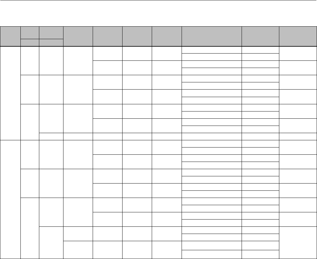
Instruction Manual
D103175X012
GX Valve and Actuator
August 2011
52
Key 3 Valve Plug/Stem and Key 2 Seat Ring (Plain Bonnet, CD3MN Valve Body Material)
VALVE
SIZE
PORT
SIZE TRAVEL PLUG STYLE
VALVE
PLUG
MATERIAL
STEM
MATERIAL
SEAT RING
MATERIAL TRIM STYLE
VALVE
PLUG/STEM
PART NUMBER
SEAT RING
PART NUMBER
mm mm
DN80
(NPS 3)
36 20 Unbalanced
CD3MN S31803 CD3MN Equal Percentage GE00097X032 GE12612X052
Linear GE00098X032
CD3MN S31803 CD3MN/
PTFE Seat
Equal Percentage GE00097X032 GE12745X312
Linear GE00098X032
46 20 Unbalanced
CD3MN S31803 CD3MN Equal Percentage GE00095X032 GE12611X052
Linear GE00096X032
CD3MN S31803 CD3MN/
PTFE Seat
Equal Percentage GE00095X032 GE12745X322
Linear GE00096X032
70 40 Unbalanced
CD3MN S31803 CD3MN Equal Percentage GE00093X032 GE12610X052
Linear GE00094X032
CD3MN S31803 CD3MN/
PTFE Seat
Equal Percentage GE00093X032 GE12745X332
Linear GE00094X032
20 Balanced S31803 S31803 CD3MN Equal Percentage GE00087X032 GE12610X052
DN100
(NPS 4)
46 20 Unbalanced
CD3MN S31803 CD3MN Equal Percentage GE01114X032 GE12615X052
Linear GE01115X032
CD3MN S31803 CD3MN/
PTFE Seat
Equal Percentage GE01114X032 GE12745X342
Linear GE01115X032
70 40 Unbalanced
CD3MN S31803 CD3MN Equal Percentage GE01112X032 GE12614X052
Linear GE01113X032
CD3MN S31803 CD3MN/
PTFE Seat
Equal Percentage GE01112X032 GE12745X352
Linear GE01113X032
90
40 Unbalanced
CD3MN S31803 CD3MN Equal Percentage GE00091X032 GE12613X052
Linear GE00092X032
CD3MN S31803 CD3MN/
PTFE Seat
Equal Percentage GE00091X032 GE12745X362
Linear GE00092X032
20
Balanced
(Standard) S31803 S31803 CD3MN Equal Percentage GE00099X032
GE12613X052
Linear GE00100X032
Balanced
(Reduced
Capacity)
S31803 S31803 CD3MN
Equal Percentage GE00089X032
Linear GE00090X032
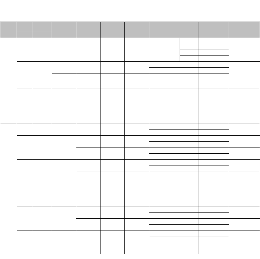
Instruction Manual
D103175X012
GX Valve and Actuator
August 2011
53
Key 3 Valve Plug/Stem and Key 2 Seat Ring (Plain Bonnet, CF3 Valve Body Material)
VALVE
SIZE
PORT
SIZE TRAVEL PLUG STYLE
VALVE
PLUG
MATERIAL
STEM
MATERIAL
SEAT RING
MATERIAL TRIM STYLE
VALVE
PLUG/STEM
PART NUMBER
SEAT RING
PART NUMBER
mm mm
DN25
(NPS 1)
4.8 20 Unbalanced R31233 S31803 CF3 Micro-Flow Flat
1_8' GE04253X092 (1)
2_15' GE04255X052
GE04252X032
4_39' GE04256X052
9_30' GE13780X022
9.5 20
Unbalanced
(Standard) S30403 S31803 CF3 Equal Percentage GE03891X042
GE00051X042
Linear GE03893X042
Unbalanced
(Reduced
Capacity)
S30403 S31803 CF3 Equal Percentage GE08919X042
14 20 Unbalanced S30403 S31803 CF3 Equal Percentage GE03890X042 GE00049X042
Linear GE03892X042
22 20 Unbalanced
S30403 S31803 CF3 Equal Percentage GE00081X042 GE00047X042
Linear GE00082X042
S30403 S31803 CF3/
PTFE Seat
Equal Percentage GE00081X042 GE05240X032
Linear GE00082X042
DN40
(NPS
1-1/2)
14 20 Unbalanced S30403 S31803 CF3 Equal Percentage GE03890X042 GE00057X042
Linear GE03892X042
22 20 Unbalanced
S30403 S31803 CF3 Equal Percentage GE00081X042 GE00055X042
Linear GE00082X042
S30403 S31803 CF3/
PTFE Seat
Equal Percentage GE00081X042 GE05240X072
Linear GE00082X042
36 20 Unbalanced
CF3 S31803 CF3 Equal Percentage GE00083X042 GE12607X062
Linear GE00084X042
CF3 S31803 CF3/
PTFE Seat
Equal Percentage GE00083X042 GE12745X192
Linear GE00084X042
DN50
(NPS 2)
22 20 Unbalanced
S30403 S31803 CF3 Equal Percentage GE00081X042 GE00063X042
Linear GE00082X042
S30403 S31803 CF3/
PTFE Seat
Equal Percentage GE00081X042 GE05240X112
Linear GE00082X042
36 20 Unbalanced
CF3 S31803 CF3 Equal Percentage GE00083X042 GE12609X062
Linear GE00084X042
CF3 S31803 CF3/
PTFE Seat
Equal Percentage GE00083X042 GE12745X202
Linear GE00084X042
46 20 Unbalanced
CF3 S31803 CF3 Equal Percentage GE00085X042 GE12608X062
Linear GE00086X042
CF3 S31803 CF3/
PTFE Seat
Equal Percentage GE00085X042 GE12745X212
Linear GE00086X042
1. The seat ring is included in the Valve Plug / Stem Part Number.

Instruction Manual
D103175X012
GX Valve and Actuator
August 2011
54
Key 3 Valve Plug/Stem and Key 2 Seat Ring (Plain Bonnet, CF3 Valve Body Material)
VALVE
SIZE
PORT
SIZE TRAVEL PLUG STYLE
VALVE
PLUG
MATERIAL
STEM
MATERIAL
SEAT RING
MATERIAL TRIM STYLE
VALVE
PLUG/STEM
PART NUMBER
SEAT RING
PART NUMBER
mm mm
DN80
(NPS 3)
36 20 Unbalanced
CF3 S31803 CF3 Equal Percentage GE00097X042 GE12612X062
Linear GE00098X042
CF3 S31803 CF3/
PTFE Seat
Equal Percentage GE00097X042 GE12745X222
Linear GE00098X042
46 20 Unbalanced
CF3 S31803 CF3 Equal Percentage GE00095X042 GE12611X062
Linear GE00096X042
CF3 S31803 CF3/
PTFE Seat
Equal Percentage GE00095X042 GE12745X232
Linear GE00096X042
70
40 Unbalanced
CF3 S31803 CF3 Equal Percentage GE00093X042 GE12610X062
Linear GE00094X042
CF3 S31803 CF3/
PTFE Seat
Equal Percentage GE00093X042 GE12745X242
Linear GE00094X042
20 Balanced S30403 S31803 CF3 Equal Percentage GE00087X042 GE12610X062
Linear GE00088X042
DN100
(NPS 4)
46 20 Unbalanced
CF3 S31803 CF3 Equal Percentage GE01114X042 GE12615X062
Linear GE01115X042
CF3 S31803 CF3/
PTFE Seat
Equal Percentage GE01114X042 GE12745X252
Linear GE01115X042
70 40 Unbalanced
CF3 S31803 CF3 Equal Percentage GE01112X042 GE12614X062
Linear GE01113X042
CF3 S31803 CF3/
PTFE Seat
Equal Percentage GE01112X042 GE12745X262
Linear GE01113X042
90
40 Unbalanced
CF3 S31803 CF3 Equal Percentage GE00091X042 GE12613X062
Linear GE00092X042
CF3 S31803 CF3/
PTFE Seat
Equal Percentage GE00091X042 GE12745X272
Linear GE00092X042
20
Balanced
(Standard) S30403 S31803 CF3 Equal Percentage GE00099X042
GE12613X062
Linear GE00100X042
Balanced
(Reduced
Capacity)
S30403 S31803 CF3
Equal Percentage GE00089X042
Linear GE00090X042
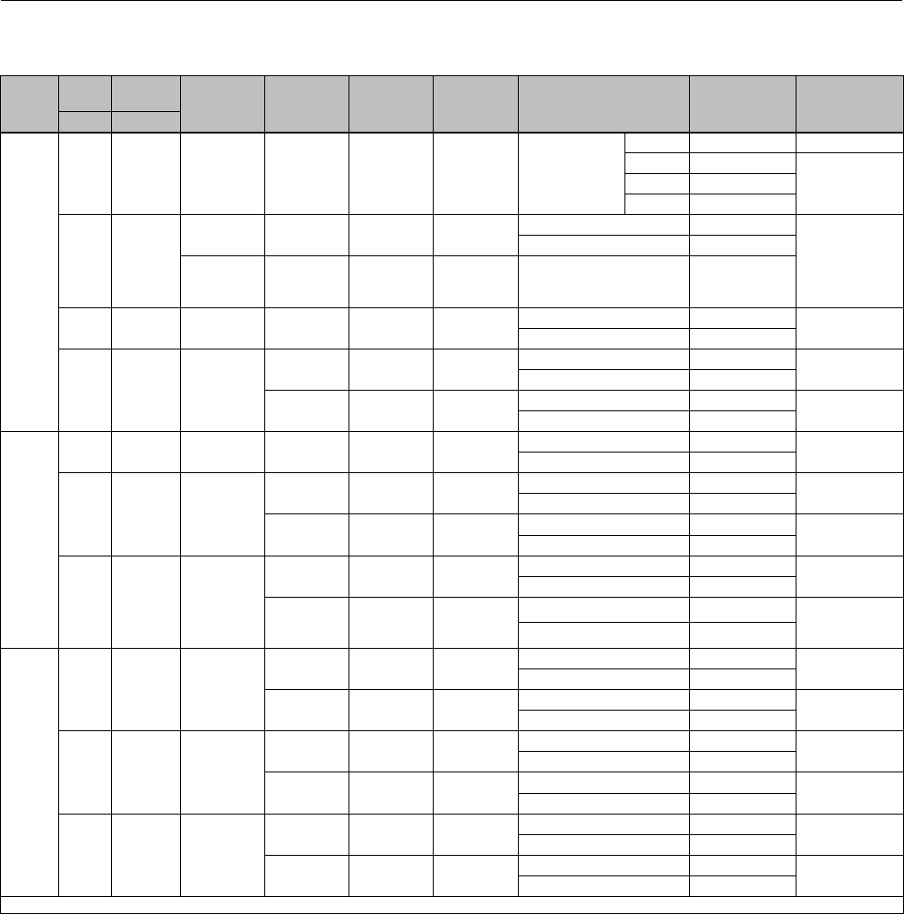
Instruction Manual
D103175X012
GX Valve and Actuator
August 2011
55
Key 3 Valve Plug/Stem and Key 2 Seat Ring (Plain Bonnet, CN7M and CW2M Valve Body Material)
VALVE
SIZE
PORT
SIZE TRAVEL PLUG STYLE
VALVE
PLUG
MATERIAL
STEM
MATERIAL
SEAT RING
MATERIAL TRIM STYLE
VALVE
PLUG/STEM
PART NUMBER
SEAT RING
PART NUMBER
mm mm
DN25
(NPS 1)
4.8 20 Unbalanced R31233 N06022 CW2M Micro-Flow Flat
1_8' GE04253X072 (1)
2_15' GE04255X072
GE04252X042
4_39' GE04256X072
9_30' GE13780X032
9.5 20
Unbalanced
(Standard) N06022 N06022 CW2M Equal Percentage GE03891X052
GE00051X052
Linear GE03893X052
Unbalanced
(Reduced
Capacity)
N06022 N06022 CW2M Equal Percentage GE08919X052
14 20 Unbalanced N06022 N06022 CW2M Equal Percentage GE03890X052 GE00049X052
Linear GE03892X052
22 20 Unbalanced
N06022 N06022 CW2M Equal Percentage GE00081X052 GE00047X052
Linear GE00082X052
N06022 N06022 CW2M/
PTFE Seat
Equal Percentage GE00081X052 GE05240X042
Linear GE00082X052
DN40
(NPS
1-1/2)
14 20 Unbalanced N06022 N06022 CW2M Equal Percentage GE03890X052 GE00057X052
Linear GE03892X052
22 20 Unbalanced
N06022 N06022 CW2M Equal Percentage GE00081X052 GE00055X052
Linear GE00082X052
N06022 N06022 CW2M/
PTFE Seat
Equal Percentage GE00081X052 GE05240X082
Linear GE00082X052
36 20 Unbalanced
CW2M N06022 CW2M Equal Percentage GE00083X072 GE12607X032
Linear GE00084X072
CW2M N06022
CW2M/
CoCr-A Bore
PTFE Seat
Equal Percentage GE00083X072
GE12745X102
Linear GE00084X072
DN50
(NPS 2)
22 20 Unbalanced
N06022 N06022 CW2M Equal Percentage GE00081X052 GE00063X052
Linear GE00082X052
N06022 N06022 CW2M/
PTFE Seat
Equal Percentage GE00081X052 GE05240X122
Linear GE00082X052
36 20 Unbalanced
CW2M N06022 CW2M Equal Percentage GE00083X072 GE12609X032
Linear GE00084X072
CW2M N06022 CW2M/
PTFE Seat
Equal Percentage GE00083X072 GE12745X112
Linear GE00084X072
46 20 Unbalanced
CW2M N06022 CW2M Equal Percentage GE00085X072 GE12608X032
Linear GE00086X072
CW2M N06022 CW2M/
PTFE Seat
Equal Percentage GE00085X072 GE12745X122
Linear GE00086X072
1. The seat ring is included in the Valve Plug / Stem Part Number.
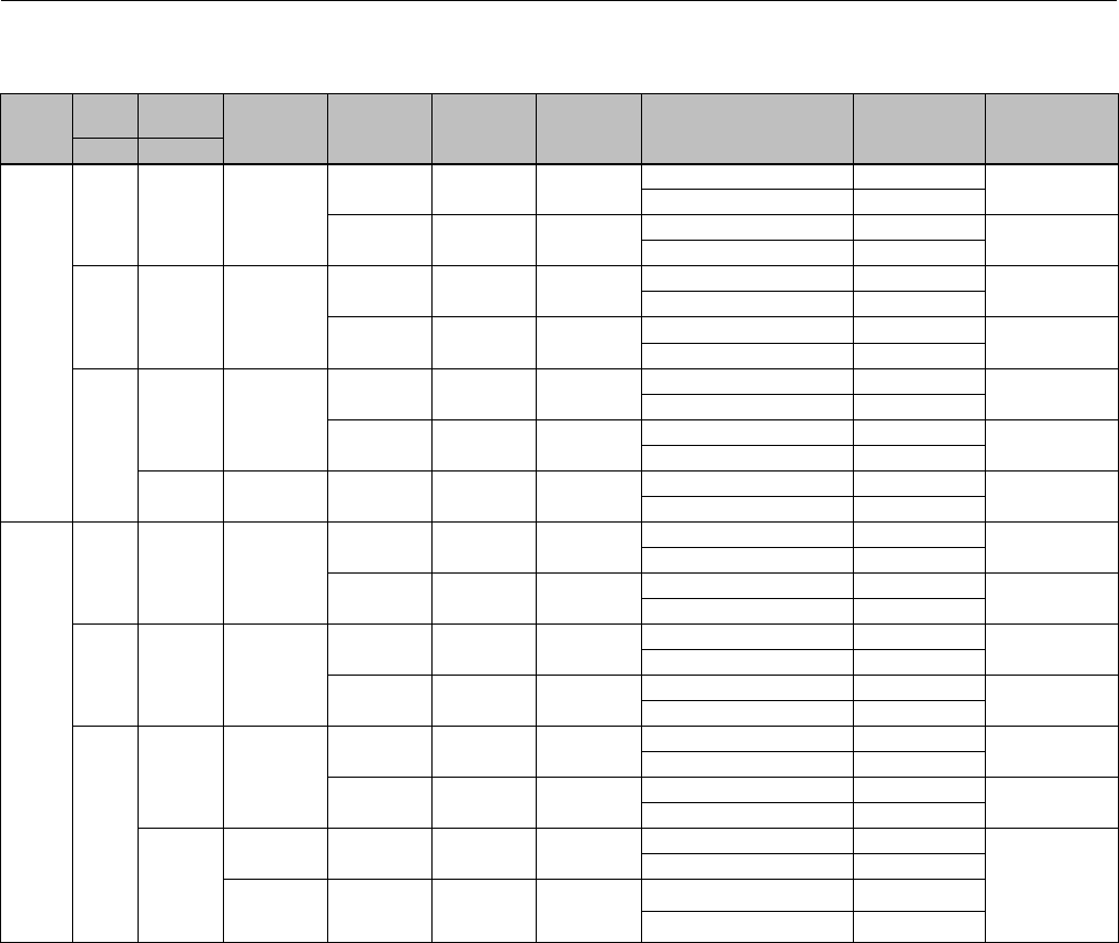
Instruction Manual
D103175X012
GX Valve and Actuator
August 2011
56
Key 3 Valve Plug/Stem and Key 2 Seat Ring (Plain Bonnet, CN7M and CW2M Valve Body Material)
VALVE
SIZE
PORT
SIZE TRAVEL PLUG STYLE
VALVE
PLUG
MATERIAL
STEM
MATERIAL
SEAT RING
MATERIAL TRIM STYLE
VALVE
PLUG/STEM
PART NUMBER
SEAT RING
PART NUMBER
mm mm
DN80
(NPS 3)
36 20 Unbalanced
CW2M N06022 CW2M Equal Percentage GE00097X072 GE12612X032
Linear GE00098X072
CW2M N06022 CW2M/
PTFE Seat
Equal Percentage GE00097X072 GE12745X132
Linear GE00098X072
46 20 Unbalanced
CW2M N06022 CW2M Equal Percentage GE00095X072 GE12611X032
Linear GE00096X072
CW2M N06022 CW2M/
PTFE Seat
Equal Percentage GE00095X072 GE12745X142
Linear GE00096X072
70
40 Unbalanced
CW2M N06022 CW2M Equal Percentage GE00093X072 GE12610X032
Linear GE00094X072
CW2M N06022 CW2M/
PTFE Seat
Equal Percentage GE00093X072 GE12745X152
Linear GE00094X072
20 Balanced N06022 N06022 CW2M Equal Percentage GE00087X062 GE12610X032
Linear GE00088X062
DN100
(NPS 4)
46 20 Unbalanced
CW2M N06022 CW2M Equal Percentage GE01114X052 GE12615X032
Linear GE01115X052
CW2M N06022 CW2M/
PTFE Seat
Equal Percentage GE01114X052 GE12745X162
Linear GE01115X052
70 40 Unbalanced
CW2M N06022 CW2M Equal Percentage GE01112X072 GE12614X032
Linear GE01113X072
CW2M N06022 CW2M/
PTFE Seat
Equal Percentage GE01112X072 GE12745X172
Linear GE01113X072
90
40 Unbalanced
CW2M N06022 CW2M Equal Percentage GE00091X072 GE12613X032
Linear GE00092X072
CW2M N06022 CW2M/
PTFE Seat
Equal Percentage GE00091X072 GE12745X182
Linear GE00092X072
20
Balanced
(Standard) N06022 N06022 CW2M Equal Percentage GE00099X062
GE12613X032
Linear GE00100X062
Balanced
(Reduced
Capacity)
N06022 N06022 CW2M
Equal Percentage GE00089X062
Linear GE00090X062
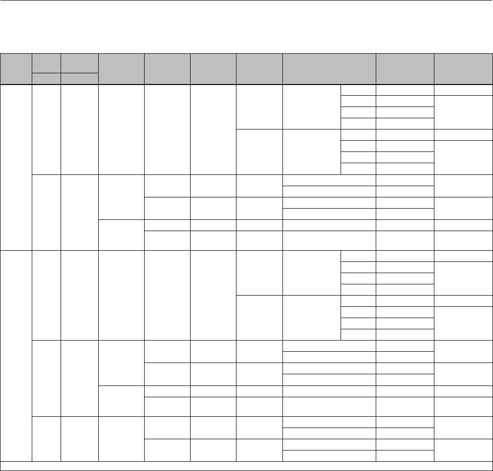
Instruction Manual
D103175X012
GX Valve and Actuator
August 2011
57
Key 3 Valve Plug/Stem and Key 2 Seat Ring (Extension Bonnet, LCC, WCC/1.0619 and CF3M/1.4409 Valve Body
Material)
VALVE
SIZE
PORT
SIZE TRAVEL PLUG STYLE
VALVE
PLUG
MATERIAL
STEM
MATERIAL
SEAT RING
MATERIAL TRIM STYLE
VALVE
PLUG/STEM
PART NUMBER
SEAT RING
PART NUMBER
mm mm
DN15
(NPS
1/2)
4.8 20 Unbalanced R31233 S31603
CF3M Micro-Flow Flat
1_8' GE04253X032 (1)
2_15' GE04255X032
GE04252X012
4_39' GE04256X032
9_30' GE04253X112
S31603/
CoCr-A Seat Micro-Flow Flat
1_8' GE04253X112 (1)
2_15' GE04255X032
GE04252X052
4_39' GE04256X032
9_30' GE04253X112
9.5 20
Unbalanced
(Standard)
S31603 S31603 CF3M Equal Percentage GE03891X012 GE00051X012
Linear GE03893X012
S31603/
CoCr-A Seat S20910 SST CF3M/
CoCr-A Seat
Equal Percentage GE03891X022 GE00051X062
Linear GE03893X022
Unbalanced
(Reduced
Capacity)
S31603 S31603 CF3M Equal Percentage GE08919X012 GE00051X012
S31603/
CoCr-A Seat S20910 SST CF3M/
CoCr-A Seat Equal Percentage GE08919X022 GE00051X062
DN20
(NPS
3/4)
4.8 20 Unbalanced R31233 S31603
CF3M Micro-Flow Flat
1_8' GE04253X032 (1)
2_15' GE04255X032
GE04252X012
4_39' GE04256X032
9_30' GE04253X112
S31603/
CoCr-A Seat Micro-Flow Flat
1_8' GE04253X112 (1)
2_15' GE04255X032
GE04252X052
4_39' GE04256X032
9_30' GE04253X112
9.5 20
Unbalanced
(Standard)
S31603 S31603 CF3M Equal Percentage GE03891X012 GE00051X012
Linear GE03893X012
S31603/
CoCr-A Seat S20910 SST CF3M/
CoCr-A Seat
Equal Percentage GE03891X022 GE00051X062
Linear GE03893X022
Unbalanced
(Reduced
Capacity)
S31603 S31603 CF3M Equal Percentage GE08919X012 GE00051X012
S31603/
CoCr-A Seat S20910 SST CF3M/
CoCr-A Seat Equal Percentage GE08919X022 GE00051X062
14 20 Unbalanced
S31603 S31603 CF3M Equal Percentage GE03890X012 GE00049X012
Linear GE03892X012
S31603/
CoCr-A Seat S20910 SST CF3M/
CoCr-A Seat
Equal Percentage GE03890X022 GE00049X062
Linear GE03892X022
1. The seat ring is included in the Valve Plug / Stem Part Number.
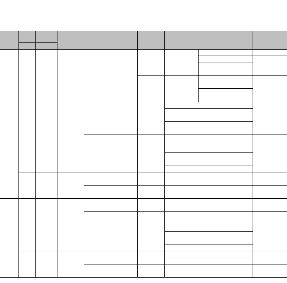
Instruction Manual
D103175X012
GX Valve and Actuator
August 2011
58
Key 3 Valve Plug/Stem and Key 2 Seat Ring (Extension Bonnet, LCC, WCC/1.0619 and CF3M/1.4409 Valve Body
Material)
VALVE
SIZE
PORT
SIZE TRAVEL PLUG STYLE
VALVE
PLUG
MATERIAL
STEM
MATERIAL
SEAT RING
MATERIAL TRIM STYLE
VALVE
PLUG/STEM
PART NUMBER
SEAT RING
PART NUMBER
mm mm
DN25
(NPS 1)
4.8 20 Unbalanced R31233 S31603
CF3M Micro-Flow Flat
1_8' GE04253X032 (1)
2_15' GE04255X032
GE04252X012
4_39' GE04256X032
9_30' GE13780X012
S31603/
CoCr-A Seat Micro-Flow Flat
1_8' GE04253X112 (1)
2_15' GE04255X032
GE04252X052
4_39' GE04256X032
9_30' GE13780X012
9.5 20
Unbalanced
(Standard)
S31603 S31603 CF3M Equal Percentage GE03891X012 GE00051X012
Linear GE03893X012
S31603/
CoCr-A Seat S20910 SST CF3M/
CoCr-A Seat
Equal Percentage GE03891X022 GE00051X062
Linear GE03893X022
Unbalanced
(Reduced
Capacity)
S31603 S31603 CF3M Equal Percentage GE08919X012 GE00051X012
S31603/
CoCr-A Seat S20910 SST CF3M/
CoCr-A Seat Equal Percentage GE08919X022 GE00051X062
14 20 Unbalanced
S31603 S31603 CF3M Equal Percentage GE03890X012 GE00049X012
Linear GE03892X012
S31603/
CoCr-A Seat S20910 SST CF3M/
CoCr-A Seat
Equal Percentage GE03890X022 GE00049X062
Linear GE03892X022
22 20 Unbalanced
S31603 S31603 CF3M Equal Percentage GE00081X012 GE00047X012
Linear GE00082X012
S31603/
CoCr-A Seat S20910 SST CF3M/
CoCr-A Seat
Equal Percentage GE00081X022 GE00047X062
Linear GE00082X022
DN40
(NPS
1-1/2)
14 20 Unbalanced
S31603 S31603 CF3M Equal Percentage GE03890X012 GE00057X012
Linear GE03892X012
S31603/
CoCr-A Seat S20910 SST CF3M/
CoCr-A Seat
Equal Percentage GE03890X022 GE00057X062
Linear GE03892X022
22 20 Unbalanced
S31603 S31603 CF3M Equal Percentage GE00081X012 GE00055X012
Linear GE00082X012
S31603/
CoCr-A Seat S20910 SST CF3M/
CoCr-A Seat
Equal Percentage GE00081X022 GE00055X062
Linear GE00082X022
36 20 Unbalanced
CF3M S31603 CF3M/
CoCr-A Seat
Equal Percentage GE00083X012 GE00053X062
Linear GE00084X012
CF3M/
CoCr-A Seat S20910 SST CF3M/
CoCr-A Seat
Equal Percentage GE00083X022 GE00053X062
Linear GE00084X022
1. The seat ring is included in the Valve Plug / Stem Part Number.
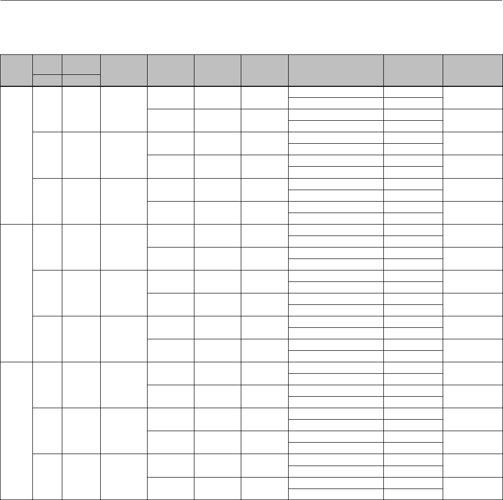
Instruction Manual
D103175X012
GX Valve and Actuator
August 2011
59
Key 3 Valve Plug/Stem and Key 2 Seat Ring (Extension Bonnet, LCC, WCC/1.0619 and CF3M/1.4409 Valve Body
Material)
VALVE
SIZE
PORT
SIZE TRAVEL PLUG STYLE
VALVE
PLUG
MATERIAL
STEM
MATERIAL
SEAT RING
MATERIAL TRIM STYLE
VALVE
PLUG/STEM
PART NUMBER
SEAT RING
PART NUMBER
mm mm
DN50
(NPS 2)
22 20 Unbalanced
S31603 S31603 CF3M Equal Percentage GE00081X012 GE00063X012
Linear GE00082X012
S31603/
CoCr-A Seat S20910 SST CF3M/
CoCr-A Seat
Equal Percentage GE00081X022 GE00063X062
Linear GE00082X022
36 20 Unbalanced
CF3M S31603 CF3M/
CoCr-A Seat
Equal Percentage GE00083X012 GE00061X062
Linear GE00084X012
CF3M/
CoCr-A Seat S20910 SST CF3M/
CoCr-A Seat
Equal Percentage GE00083X022 GE00061X062
Linear GE00084X022
46 20 Unbalanced
CF3M S31603 CF3M/
CoCr-A Seat
Equal Percentage GE00085X012 GE00059X062
Linear GE00086X012
CF3M/
CoCr-A Seat S20910 SST CF3M/
CoCr-A Seat
Equal Percentage GE00085X022 GE00059X062
Linear GE00086X022
DN80
(NPS 3)
36 20 Unbalanced
CF3M S31603 CF3M/
CoCr-A Seat
Equal Percentage GE00097X012 GE00069X062
Linear GE00098X012
CF3M/
CoCr-A Seat S20910 SST CF3M/
CoCr-A Seat
Equal Percentage GE00097X022 GE00069X062
Linear GE00098X022
46 20 Unbalanced
CF3M S31603 CF3M/
CoCr-A Seat
Equal Percentage GE00095X012 GE00067X062
Linear GE00096X012
CF3M/
CoCr-A Seat S20910 SST CF3M/
CoCr-A Seat
Equal Percentage GE00095X022 GE00067X062
Linear GE00096X022
70 40 Unbalanced
CF3M S31603 CF3M/
CoCr-A Seat
Equal Percentage GE00093X012 GE00065X062
Linear GE00094X012
CF3M/
CoCr-A Seat S20910 SST CF3M/
CoCr-A Seat
Equal Percentage GE00093X022 GE00065X062
Linear GE00094X022
DN100
(NPS 4)
46 20 Unbalanced
CF3M S31603 CF3M/
CoCr-A Seat
Equal Percentage GE01114X012 GE00075X062
Linear GE01115X012
CF3M/
CoCr-A Seat S20910 SST CF3M/
CoCr-A Seat
Equal Percentage GE01114X022 GE00075X062
Linear GE01115X022
70 40 Unbalanced
CF3M S31603 CF3M/
CoCr-A Seat
Equal Percentage GE01112X012 GE00073X062
Linear GE01113X012
CF3M/
CoCr-A Seat S20910 SST CF3M/
CoCr-A Seat
Equal Percentage GE01112X022 GE00073X062
Linear GE01113X022
90 40 Unbalanced
CF3M S31603 CF3M/
CoCr-A Seat
Equal Percentage GE00091X012 GE00071X062
Linear GE00092X012
CF3M/
CoCr-A Seat S20910 SST CF3M/
CoCr-A Seat
Equal Percentage GE00091X022 GE00071X062
Linear GE00092X022
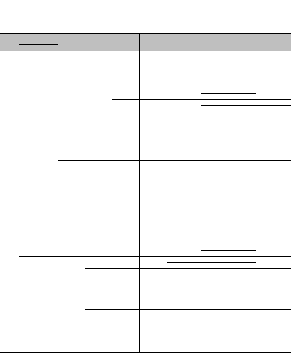
Instruction Manual
D103175X012
GX Valve and Actuator
August 2011
60
Key 3 Valve Plug/Stem and Key 2 Seat Ring (Bellows Bonnet, LCC, WCC/1.0619 and CF3M/1.4409 Valve Body
Material)
VALVE
SIZE
PORT
SIZE TRAVEL PLUG STYLE VALVE PLUG
MATERIAL
STEM
MATERIAL
SEAT RING
MATERIAL TRIM STYLE
VALVE
PLUG/STEM
PART NUMBER
SEAT RING PART
NUMBER
mm mm
DN15
(NPS
1/2)
4.8 20 Unbalanced R31233
S31603
CF3M Micro-Flow Flat
1_8' GE04253X032 (1)
2_15' GE04255X032
GE04252X012
4_39' GE04256X032
9_30' GE13780X012
S31603/
CoCr-A Seat Micro-Flow Flat
1_8' GE04253X112 (1)
2_15' GE04255X032
GE04252X052
4_39' GE04256X032
9_30' GE13780X012
N06022 CW2M Micro-Flow Flat
1_8' GE04253X072 (1)
2_15' GE04255X072
GE04252X042
4_39' GE04256X072
9_30' GE13780X032
9.5 20
Unbalanced
(Standard)
S31603 S31603 CF3M Equal Percentage GE03891X012 GE00051X012
Linear GE03893X012
S31603/
CoCr-A Seat S20910 SST CF3M/
CoCr-A Seat
Equal Percentage GE03891X022 GE00051X062
Linear GE03893X022
N06022 N06022 CW2M Equal Percentage GE03891X052 GE00051X052
Linear GE03893X052
Unbalanced
(Reduced
Capacity)
S31603 S31603 CF3M Equal Percentage GE08919X012 GE00051X012
S31603/
CoCr-A Seat S20910 SST CF3M/
CoCr-A Seat Equal Percentage GE08919X022 GE00051X062
N06022 N06022 CW2M Equal Percentage GE08919X052 GE00051X052
DN20
(NPS
3/4)
4.8 20 Unbalanced R31233
S31603
CF3M Micro-Flow Flat
1_8' GE04253X032 (1)
2_15' GE04255X032
GE04252X012
4_39' GE04256X032
9_30' GE13780X012
S31603/
CoCr-A Seat Micro-Flow Flat
1_8' GE04253X112 (1)
2_15' GE04255X032
GE04252X052
4_39' GE04256X032
9_30' GE13780X012
N06022 CW2M Micro-Flow Flat
1_8' GE04253X072 (1)
2_15' GE04255X072
GE04252X042
4_39' GE04256X072
9_30' GE13780X032
9.5 20
Unbalanced
(Standard)
S31603 S31603 CF3M Equal Percentage GE03891X012 GE00051X012
Linear GE03893X012
S31603/
CoCr-A Seat S20910 SST CF3M/
CoCr-A Seat
Equal Percentage GE03891X022 GE00051X062
Linear GE03893X022
N06022 N06022 CW2M Equal Percentage GE03891X052 GE00051X052
Linear GE03893X052
Unbalanced
(Reduced
Capacity)
S31603 S31603 CF3M Equal Percentage GE08919X012 GE00051X012
S31603/
CoCr-A Seat S20910 SST CF3M/
CoCr-A Seat Equal Percentage GE08919X022 GE00051X062
N06022 N06022 CW2M Equal Percentage GE08919X052 GE00051X052
14 20 Unbalanced
S31603 S31603 CF3M Equal Percentage GE03890X012 GE00049X012
Linear GE03892X012
S31603/
CoCr-A Seat S20910 SST CF3M/
CoCr-A Seat
Equal Percentage GE03890X022 GE00049X062
Linear GE03892X022
N06022 N06022 CW2M Equal Percentage GE03890X052 GE00049X052
Linear GE03892X052
1. The seat ring is included in the Valve Plug / Stem Part Number.
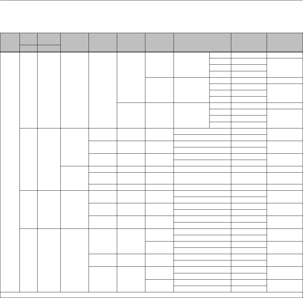
Instruction Manual
D103175X012
GX Valve and Actuator
August 2011
61
Key 3 Valve Plug/Stem and Key 2 Seat Ring (Bellows Bonnet, LCC, WCC/1.0619 and CF3M/1.4409 Valve Body
Material)
VALVE
SIZE
PORT
SIZE TRAVEL PLUG STYLE
VALVE
PLUG
MATERIAL
STEM
MATERIAL
SEAT RING
MATERIAL TRIM STYLE
VALVE
PLUG/STEM
PART NUMBER
SEAT RING
PART NUMBER
mm mm
DN25
(NPS 1)
4.8 20 Unbalanced R31233
S31603
CF3M Micro-Flow Flat
1_8' GE04253X032 (1)
2_15' GE04255X032
GE04252X012
4_39' GE04256X032
9_30' GE13780X012
S31603/
CoCr-A Seat Micro-Flow Flat
1_8' GE04253X112 (1)
2_15' GE04255X032
GE04252X052
4_39' GE04256X032
9_30' GE13780X012
N06022 CW2M Micro-Flow Flat
1_8' GE04253X072 (1)
2_15' GE04255X072
GE04252X042
4_39' GE04256X072
9_30' GE13780X032
9.5 20
Unbalanced
(Standard)
S31603 S31603 CF3M Equal Percentage GE03891X012 GE00051X012
Linear GE03893X012
S31603/
CoCr-A Seat S20910 SST CF3M/
CoCr-A Seat
Equal Percentage GE03891X022 GE00051X062
Linear GE03893X022
N06022 N06022 CW2M Equal Percentage GE03891X052 GE00051X052
Linear GE03893X052
Unbalanced
(Reduced
Capacity)
S31603 S31603 CF3M Equal Percentage GE08919X012 GE00051X012
S31603/
CoCr-A Seat S20910 SST CF3M/
CoCr-A Seat Equal Percentage GE08919X022 GE00051X062
N06022 N06022 CW2M Equal Percentage GE08919X052 GE00051X052
14 20 Unbalanced
S31603 S31603 CF3M Equal Percentage GE03890X012 GE00049X012
Linear GE03892X012
S31603/
CoCr-A Seat S20910 SST CF3M/
CoCr-A Seat
Equal Percentage GE03890X022 GE00049X062
Linear GE03892X022
N06022 N06022 CW2M Equal Percentage GE03890X052 GE00049X052
Linear GE03892X052
22 20 Unbalanced
S31603 S31603
CF3M Equal Percentage GE00081X012 GE00047X012
Linear GE00082X012
CF3M/
PTFE Seat
Equal Percentage GE00081X012 GE05240X012
Linear GE00082X012
S31603/
CoCr-A Seat S20910 SST CF3M/
CoCr-A Seat
Equal Percentage GE00081X022 GE00047X062
Linear GE00082X022
N06022 N06022
CW2M Equal Percentage GE00081X052 GE00047X052
Linear GE00082X052
CW2M/
PTFE Seat
Equal Percentage GE00081X052 GE05240X042
Linear GE00082X052
1. The seat ring is included in the Valve Plug / Stem Part Number.
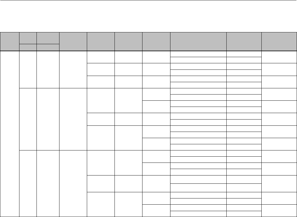
Instruction Manual
D103175X012
GX Valve and Actuator
August 2011
62
Key 3 Valve Plug/Stem and Key 2 Seat Ring (Bellows Bonnet, LCC, WCC/1.0619 and CF3M/1.4409 Valve Body
Material)
VALVE
SIZE
PORT
SIZE TRAVEL PLUG STYLE
VALVE
PLUG
MATERIAL
STEM
MATERIAL
SEAT RING
MATERIAL TRIM STYLE
VALVE
PLUG/STEM
PART NUMBER
SEAT RING
PART NUMBER
mm mm
DN40
(NPS
1-1/2)
14 20 Unbalanced
S31603 S31603 CF3M Equal Percentage GE03890X012 GE00057X012
Linear GE03892X012
S31603/
CoCr-A Seat S20910 SST CF3M/
CoCr-A Seat
Equal Percentage GE03890X022 GE00057X062
Linear GE03892X022
N06022 N06022 CW2M Equal Percentage GE03890X052 GE00057X052
Linear GE03892X052
22 20 Unbalanced
S31603 S31603
CF3M Equal Percentage GE00081X012 GE00055X012
Linear GE00082X012
CF3M/
PTFE Seat
Equal Percentage GE00081X012 GE05240X052
Linear GE00082X012
S31603/
CoCr-A Seat S20910 SST CF3M/
CoCr-A Seat
Equal Percentage GE00081X022 GE00055X062
Linear GE00082X022
N06022 N06022
CW2M Equal Percentage GE00081X052 GE00055X052
Linear GE00082X052
CW2M/
PTFE Seat
Equal Percentage GE00081X052 GE05240X082
Linear GE00082X052
36 20 Unbalanced
CF3M S31603
CF3M Equal Percentage GE00083X012 GE12607X012
Linear GE00084X012
CF3M/
PTFE Seat
Equal Percentage GE00083X012 GE12745X012
Linear GE00084X012
CF3M/
CoCr-A Seat S20910 SST
CF3M/
CoCr-A Seat
and Guide
Equal Percentage GE00083X022
GE00053X062
Linear GE00084X022
CW2M N06022
CW2M Equal Percentage GE00083X072 GE12607X032
Linear GE00084X072
CW2M/
PTFE Seat
Equal Percentage GE00083X072 GE12745X102
Linear GE00084X072
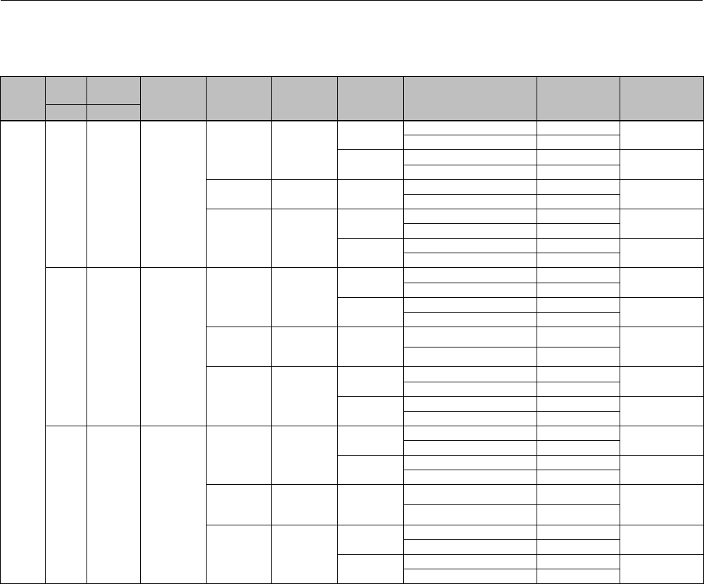
Instruction Manual
D103175X012
GX Valve and Actuator
August 2011
63
Key 3 Valve Plug/Stem and Key 2 Seat Ring (Bellows Bonnet, LCC, WCC/1.0619 and CF3M/1.4409 Valve Body
Material)
VALVE
SIZE
PORT
SIZE TRAVEL PLUG STYLE
VALVE
PLUG
MATERIAL
STEM
MATERIAL
SEAT RING
MATERIAL TRIM STYLE
VALVE
PLUG/STEM
PART NUMBER
SEAT RING
PART NUMBER
mm mm
DN50
(NPS 2)
22 20 Unbalanced
S31603 S31603
CF3M Equal Percentage GE00081X012 GE00063X012
Linear GE00082X012
CF3M/
PTFE Seat
Equal Percentage GE00081X012 GE05240X092
Linear GE00082X012
S31603/
CoCr-A Seat S20910 SST CF3M/
CoCr-A Seat
Equal Percentage GE00081X022 GE00063X062
Linear GE00082X022
N06022 N06022
CW2M Equal Percentage GE00081X052 GE00063X052
Linear GE00082X052
CW2M/
PTFE Seat
Equal Percentage GE00081X052 GE05240X122
Linear GE00082X052
36 20 Unbalanced
CF3M S31603
CF3M Equal Percentage GE00083X012 GE12609X012
Linear GE00084X012
CF3M/
PTFE Seat
Equal Percentage GE00083X012 GE12745X022
Linear GE00084X012
CF3M/
CoCr-A Seat S20910 SST
CF3M/
CoCr-A Seat
and Guide
Equal Percentage GE00083X022
GE00061X062
Linear GE00084X022
CW2M N06022
CW2M Equal Percentage GE00083X072 GE12609X032
Linear GE00084X072
CW2M/
PTFE Seat
Equal Percentage GE00083X072 GE12745X112
Linear GE00084X072
46 20 Unbalanced
CF3M S31603
CF3M Equal Percentage GE00085X012 GE12608X012
Linear GE00086X012
CF3M/
PTFE Seat
Equal Percentage GE00085X012 GE12745X032
Linear GE00086X012
CF3M/
CoCr-A Seat S20910 SST
CF3M/
CoCr-A Seat
and Guide
Equal Percentage GE00085X022
GE00059X062
Linear GE00086X022
CW2M N06022
CW2M Equal Percentage GE00085X072 GE12608X032
Linear GE00086X072
CW2M/
PTFE Seat
Equal Percentage GE00085X072 GE12745X122
Linear GE00086X072
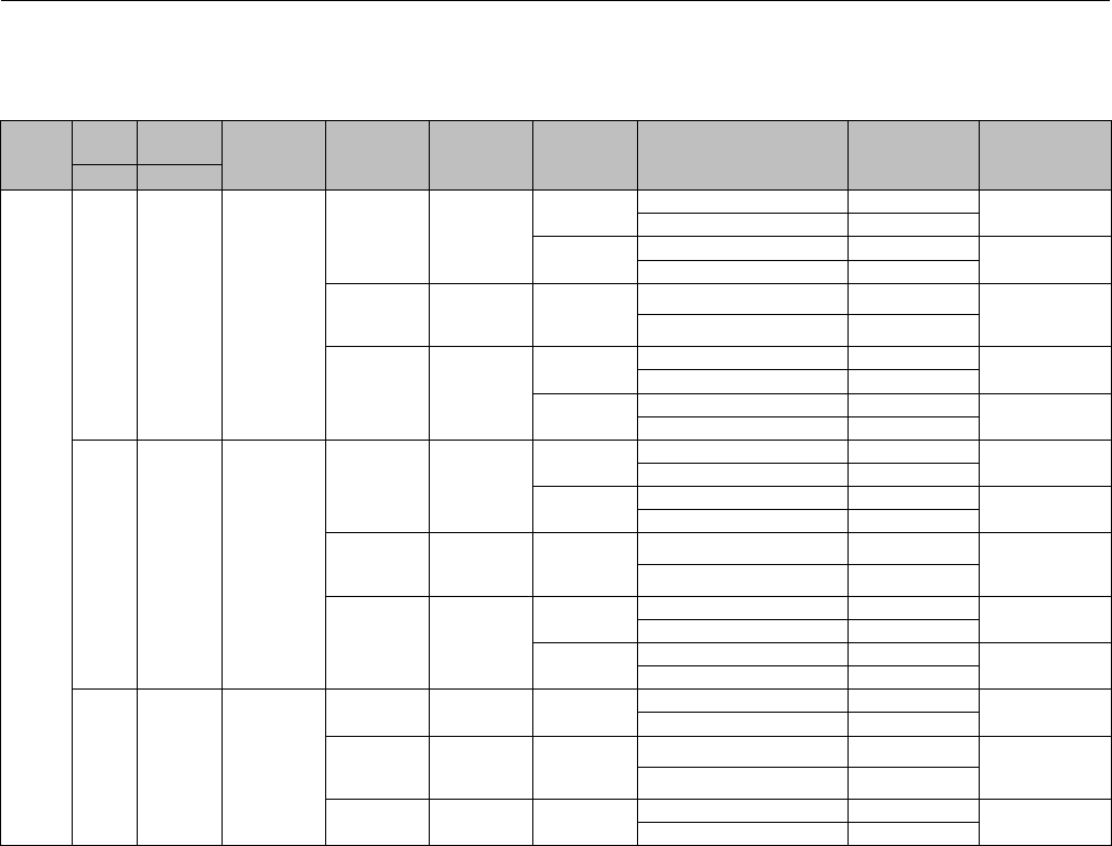
Instruction Manual
D103175X012
GX Valve and Actuator
August 2011
64
Key 3 Valve Plug/Stem and Key 2 Seat Ring (Bellows Bonnet, LCC, WCC/1.0619 and CF3M/1.4409 Valve Body
Material)
VALVE
SIZE
PORT
SIZE TRAVEL PLUG STYLE
VALVE
PLUG
MATERIAL
STEM
MATERIAL
SEAT RING
MATERIAL TRIM STYLE
VALVE
PLUG/STEM
PART NUMBER
SEAT RING
PART NUMBER
mm mm
DN80
(NPS 3)
36 20 Unbalanced
CF3M S31603
CF3M Equal Percentage GE00097X012 GE12612X012
Linear GE00098X012
CF3M/
PTFE Seat
Equal Percentage GE00097X012 GE12745X042
Linear GE00098X012
CF3M/
CoCr-A Seat S20910 SST
CF3M/
CoCr-A Seat
and Guide
Equal Percentage GE00097X022
GE00069X062
Linear GE00098X022
CW2M N06022
CW2M Equal Percentage GE00097X072 GE12612X032
Linear GE00098X072
CW2M/
PTFE Seat
Equal Percentage GE00097X072 GE12745X132
Linear GE00098X072
46 20 Unbalanced
CF3M S31603
CF3M Equal Percentage GE00095X012 GE12611X012
Linear GE00096X012
CF3M/
PTFE Seat
Equal Percentage GE00095X012 GE12745X052
Linear GE00096X012
CF3M/
CoCr-A Seat S20910 SST
CF3M/
CoCr-A Seat
and Guide
Equal Percentage GE00095X022
GE00067X062
Linear GE00096X022
CW2M N06022
CW2M Equal Percentage GE00095X072 GE12611X032
Linear GE00096X072
CW2M/
PTFE Seat
Equal Percentage GE00095X072 GE12745X142
Linear GE00096X072
70 20 Balanced
S31603 S31603 CF3M Equal Percentage GE00087X012 GE12610X012
Linear GE00088X012
S31603/
CoCr-A Seat S20910 SST
CF3M/
CoCr-A Seat
and Guide
Equal Percentage GE00087X022
GE00065X062
Linear GE00088X022
N06022 N06022 CW2M Equal Percentage GE00087X062 GE12610X032
Linear GE00088X062
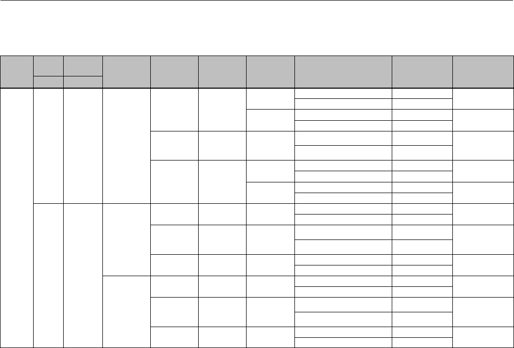
Instruction Manual
D103175X012
GX Valve and Actuator
August 2011
65
Key 3 Valve Plug/Stem and Key 2 Seat Ring (Bellows Bonnet, LCC, WCC/1.0619 and CF3M/1.4409 Valve Body
Material)
VALVE
SIZE
PORT
SIZE TRAVEL PLUG STYLE
VALVE
PLUG
MATERIAL
STEM
MATERIAL
SEAT RING
MATERIAL TRIM STYLE
VALVE
PLUG/STEM
PART NUMBER
SEAT RING
PART NUMBER
mm mm
DN100
(NPS 4)
46 20 Unbalanced
CF3M S31603
CF3M Equal Percentage GE01114X012 GE12615X012
Linear GE01115X012
CF3M/
PTFE Seat
Equal Percentage GE01114X012 GE12745X072
Linear GE01115X012
CF3M/
CoCr-A Seat S20910 SST
CF3M/
CoCr-A Seat
and Guide
Equal Percentage GE01114X022
GE00075X062
Linear GE01115X022
CW2M N06022
CW2M Equal Percentage GE01114X052 GE12615X032
Linear GE01115X052
CW2M/
PTFE Seat
Equal Percentage GE01114X052 GE12745X162
Linear GE01115X052
90 20
Balanced
(Standard)
S31603 S31603 CF3M Equal Percentage GE00099X012 GE12613X012
Linear GE00100X012
S31603/
CoCr-A Seat S20910 SST
CF3M/
CoCr-A Seat
and Guide
Equal Percentage GE00099X022
GE00071X062
Linear GE00100X022
N06022 N06022 CW2M Equal Percentage GE00099X062 GE12613X032
Linear GE00100X062
Balanced
(Reduced
Capacity)
S31603 S31603 CF3M Equal Percentage GE00089X012 GE12613X012
Linear GE00090X012
S31603/
CoCr-A Seat S20910 SST
CF3M/
CoCr-A Seat
and Guide
Equal Percentage GE00089X022
GE00071X062
Linear GE00090X022
N06022 N06022 CW2M Equal Percentage GE00089X062 GE12613X032
Linear GE00090X062

Instruction Manual
D103175X012
GX Valve and Actuator
August 2011
66
Key 3 Valve Plug/Stem and Key 2 Seat Ring (Bellows Bonnet, CW2M Valve Body Material)
VALVE
SIZE
PORT
SIZE TRAVEL PLUG STYLE
VALVE
PLUG
MATERIAL
STEM
MATERIAL
SEAT RING
MATERIAL TRIM STYLE
VALVE
PLUG/STEM
PART NUMBER
SEAT RING
PART NUMBER
mm mm
DN25
(NPS 1)
4.8 20 Unbalanced R31233 N06022 CW2M Micro-Flow Flat
1_8' GE04253X072 (1)
2_15' GE04255X072
GE04252X042
4_39' GE04256X072
9_30' GE13780X032
9.5 20
Unbalanced
(Standard) N06022 N06022 CW2M Equal Percentage GE03891X052
GE00051X052
Linear GE03893X052
Unbalanced
(Reduced
Capacity)
N06022 N06022 CW2M Equal Percentage GE08919X052
14 20 Unbalanced N06022 N06022 CW2M Equal Percentage GE03890X052 GE00049X052
Linear GE03892X052
22 20 Unbalanced
N06022 N06022 CW2M Equal Percentage GE00081X052 GE00047X052
Linear GE00082X052
N06022 N06022 CW2M/
PTFE Seat
Equal Percentage GE00081X052 GE05240X042
Linear GE00082X052
DN40
(NPS
1-1/2)
14 20 Unbalanced N06022 N06022 CW2M Equal Percentage GE03890X052 GE00057X052
Linear GE03892X052
22 20 Unbalanced
N06022 N06022 CW2M Equal Percentage GE00081X052 GE00055X052
Linear GE00082X052
N06022 N06022 CW2M/
PTFE Seat
Equal Percentage GE00081X052 GE05240X082
Linear GE00082X052
36 20 Unbalanced
CW2M N06022 CW2M Equal Percentage GE00083X072 GE12607X032
Linear GE00084X072
CW2M N06022
CW2M/
CoCr-A Bore
PTFE Seat
Equal Percentage GE00083X072
GE12745X102
Linear GE00084X072
DN50
(NPS 2)
22 20 Unbalanced
N06022 N06022 CW2M Equal Percentage GE00081X052 GE00063X052
Linear GE00082X052
N06022 N06022 CW2M/
PTFE Seat
Equal Percentage GE00081X052 GE05240X122
Linear GE00082X052
36 20 Unbalanced
CW2M N06022 CW2M Equal Percentage GE00083X072 GE12609X032
Linear GE00084X072
CW2M N06022 CW2M/
PTFE Seat
Equal Percentage GE00083X072 GE12745X112
Linear GE00084X072
46 20 Unbalanced
CW2M N06022 CW2M Equal Percentage GE00085X072 GE12608X032
Linear GE00086X072
CW2M N06022 CW2M/
PTFE Seat
Equal Percentage GE00085X072 GE12745X122
Linear GE00086X072
1. The seat ring is included in the Valve Plug / Stem Part Number.

Instruction Manual
D103175X012
GX Valve and Actuator
August 2011
67
Key 3 Valve Plug/Stem and Key 2 Seat Ring (Bellows Bonnet, CW2M Valve Body Material)
VALVE
SIZE
PORT
SIZE TRAVEL PLUG STYLE
VALVE
PLUG
MATERIAL
STEM
MATERIAL
SEAT RING
MATERIAL TRIM STYLE
VALVE
PLUG/STEM
PART NUMBER
SEAT RING
PART NUMBER
mm mm
DN80
(NPS 3)
36 20 Unbalanced
CW2M N06022 CW2M Equal Percentage GE00097X072 GE12612X032
Linear GE00098X072
CW2M N06022 CW2M/
PTFE Seat
Equal Percentage GE00097X072 GE12745X132
Linear GE00098X072
46 20 Unbalanced
CW2M N06022 CW2M Equal Percentage GE00095X072 GE12611X032
Linear GE00096X072
CW2M N06022 CW2M/
PTFE Seat
Equal Percentage GE00095X072 GE12745X142
Linear GE00096X072
70 20 Balanced N06022 N06022 CW2M Equal Percentage GE00087X062 GE12610X032
Linear GE00088X062
DN100
(NPS 4)
46 20 Unbalanced
CW2M N06022 CW2M Equal Percentage GE01114X052 GE12615X032
Linear GE01115X052
CW2M N06022 CW2M/
PTFE Seat
Equal Percentage GE01114X052 GE12745X162
Linear GE01115X052
90 20
Balanced
(Standard) N06022 N06022 CW2M Equal Percentage GE00099X062
GE12613X032
Linear GE00100X062
Balanced
(Reduced
Capacity)
N06022 N06022 CW2M
Equal Percentage GE00089X062
Linear GE00090X062

Instruction Manual
D103175X012
GX Valve and Actuator
August 2011
68
Emerson Process Management
Marshalltown, Iowa 50158 USA
Sorocaba, 18087 Brazil
Chatham, Kent ME4 4QZ UK
Dubai, United Arab Emirates
Singapore 128461 Singapore
www.Fisher.com
The contents of this publication are presented for informational purposes only, and while every effort has been made to ensure their accuracy, they arenot
to be construed as warranties or guarantees, express or implied, regarding the products or services described herein or their use or applicability. All sales are
governed by our terms and conditions, which are available upon request. We reserve the right to modify or improve the designs or specifications of such
products at any time without notice.
EFisher Controls International LLC 2003, 2011; All Rights Reserved
Fisher, FIELDVUE, Cavitrol, and Whisper Trim are marks owned by one of the companies in the Emerson Process Management business division of Emerson
Electric Co. Emerson Process Management, Emerson, and the Emerson logo are trademarks and service marks of Emerson Electric Co. All other marks are
the property of their respective owners.
Neither Emerson, Emerson Process Management, nor any of their affiliated entities assumes responsibility for the selection, use or maintenance
of any product. Responsibility for proper selection, use, and maintenance of any product remains solely with the purchaser and end user.
