Emerson Fisher Hp And Eh Instruction Manual
2015-03-30
: Emerson Emerson-Fisher-Hp-And-Eh-Instruction-Manual-680688 emerson-fisher-hp-and-eh-instruction-manual-680688 emerson pdf
Open the PDF directly: View PDF ![]() .
.
Page Count: 44
www.Fisher.com
FisherrEHD and EHT NPS 8 through 14
Sliding-Stem Control Valves
Contents
Introduction 1.................................
Scope of Manual 1.............................
Description 2.................................
Specifications 2...............................
Educational Services 3.........................
Installation 3..................................
Principle of Operation 5.........................
Maintenance 5.................................
Packing Lubrication 6..........................
Packing Maintenance 7.........................
Replacing Packing 7........................
Trim Removal 12..............................
EHD, EHT Valve Plug Maintenance 12.............
Lapping Seats 13..............................
Trim Replacement 14..........................
Retrofit: Installing Bore Seal Trim 17..............
Replacement of Installed Bore Seal Trim 19........
Trim Removal (Bore Seal Constructions) 19....
Lapping Metal Seats
(Bore Seal Constructions) 20..............
Remachining Metal Seats
(Bore Seal Constructions) 20..............
Trim Replacement
(Bore Seal Constructions) 20..............
Actuator Mounting 22.........................
Parts Ordering 22...............................
Parts Kits 23...................................
Parts List 25...................................
Bonnet Assembly 25...........................
Valve Assembly 27............................
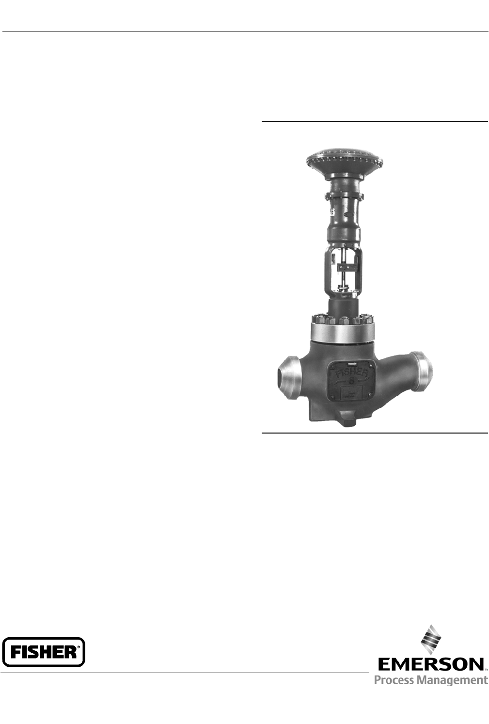
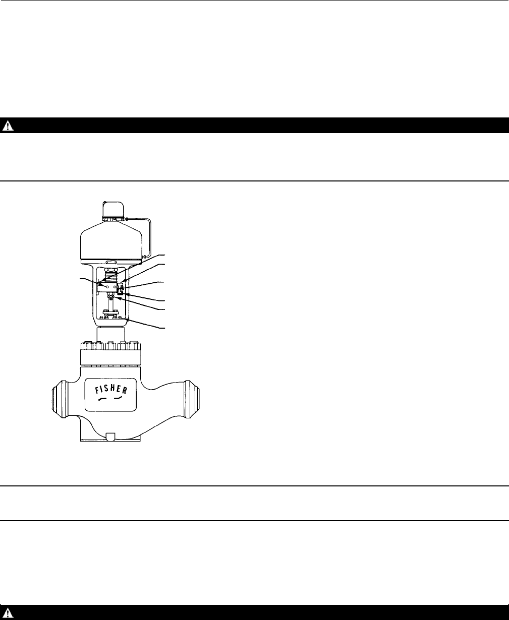
Figure 1. Fisher EH Series Control Valve
with 667 Actuator
W2992-1
Introduction
Scope of Manual
This instruction manual includes installation, maintenance, and parts ordering information for NPS 8 through 14 Fisher
EHD and EHT sliding-stem globe-style control valves. Refer to separate manuals for instructions covering the actuator,
positioner, and accessories.
Do not install, operate, or maintain an EH valve without being fully trained and qualified in valve, actuator, and
accessory installation, operation, and maintenance. To avoid personal injury or property damage, it is important to
carefully read, understand, and follow all the contents of this manual, including all safety cautions and warnings. If you
have any questions about these instructions, contact your Emerson Process Management sales office before
proceeding.
Instruction Manual
D100392X012
EH Valves NPS 8 through 14
July 2014
Instruction Manual
D100392X012
EH Valves NPS 8 through 14
July 2014
2
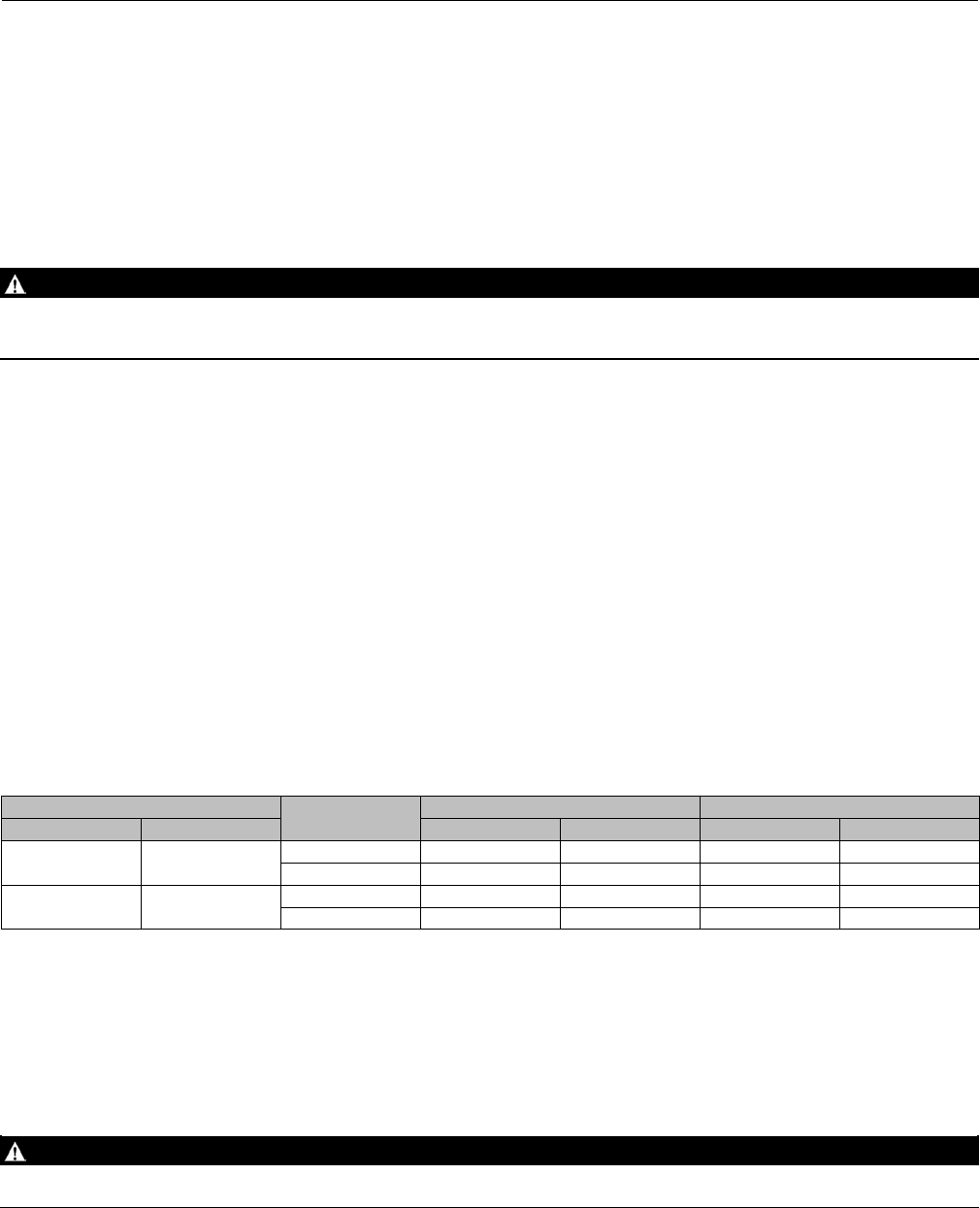
Table 1. Specifications
End Connection Styles(1)
Buttwelding: All available ASME B16.25 schedules
that are compatible with ASME B16.34
pressure/temperature ratings
Flanged Ends: CL1500 or 2500 Jraised-face (RF) or
Jring-type joint (RTJ) flanges per ASME B16.5
Shutoff Classifications
See table 2
Bore seal trim: High-temperature, Class V.
See table 3
Flow Characteristic
Standard Cages: JLinear, Jequal percentage, or
Jmodified equal percentage(2)
Whisper Trim™ III Cages: JLinear or Jmodified
characteristics available upon request
Flow Direction
Normallyflowdown(inthroughthecagewindows
and out through the seat ring) for all cage styles
except for applications using either a Whisper Trim III
cage or a diverter cone plug, both of which are flow
up only
Additional Specifications
For specifications such as materials, valve plug
travels, and port, yoke boss, and stem diameters, see
the Parts List section
Approximate Weights
See table 4
1. The pressure or temperature limits in this manual and any applicable standard limitations should not be exceeded.
2. Valves using an equal percentage cage may be travelled an additional 13 mm (0.5 inch) if desired to obtain additional capacity; flow characteristic becomes modified equal percentage.
Table 2. Shutoff Classifications(1)
Valve Design ANSI/FCI LEAKAGE CLASS
EHD III–Standard
IV–Optional
EHT IV–Standard
V–Optional
EHT w/ PEEK(2) Anti-Extrusion Rings V to 316_C (600_F)
1. Per ANSI/FCI 70-2 and IEC 60534-4
2. Poly Ether Ether Ketone
Description
The EHD and EHT valves, shown in figure 1, are large, sliding-stem, high-pressure, globe-style valves. These valves
have metal seats, cage guiding, and push-down-to-close valve plug action.
The EHD and EHT valves feature balanced valve plugs. To provide a seal between the valve plug and cage, the EHD
valve plug has piston rings; the EHT valve plug has a pressure-assisted seal ring.
Bore seal trim is available for EHD valves, CL1500, NPS 8 and 10 and CL2500, NPS 8, 10, 12, and 14.
With Bore seal trim, a balanced valve can achieve high-temperature, Class V shutoff. Because the Bore seal plug seal is
formed from metal (N07718 nickel alloy) rather than an elastomer, a valve equipped with the Bore seal trim can be
appliedinprocesseswithafluidtemperatureofupto593_C (1100_F), provided other material limits are not
exceeded.
Specifications
Specifications for the EHD and EHT valves are shown in table 1.
Instruction Manual
D100392X012
EH Valves NPS 8 through 14
July 2014
3
Educational Services
For information on available courses for the Fisher EH NPS 8 through14valve,aswellasavariety of other products,
contact:
Emerson Process Management
Educational Services - Registration
Phone: 1-641-754-3771 or 1-800-338-8158
E-mail: education@emerson.com
http://www.emersonprocess.com/education
Table 3. Additional Shutoff Classification
Valve Design
(PRESSURE RATING) Valve Size, NPS Port Diameter, Inches Cage Style ANSI/FCI Leakage
Class
EHD
(CL1500)
8
10 7
Equal Percentage
Modified Equal Percentage
Linear (std. cage)
Linear (Whisper III, A1, B3, C3)
Vwith
optional Bore seal trim
EHD
(CL2500)
8
10 5.375
Equal Percentage, Modified Equal Percentage,
Linear (std. cage),
Linear (Whisper III, A1, B3, C3, D3)
Vwith
optional Bore seal trim)
12
14 7
Equal Percentage, Modified Equal Percentage,
Linear (std. cage),
Linear (Whisper III, A1, B3, C3, D3)
Vwith
optional Bore seal trim)
Table 4. Approximate Weights (Valve Body and Bonnet Assemblies)
VALVE
SIZE,
NPS
WEIGHTS
CL1500 CL2500
Buttwelding Ends Flanged Buttwelding Ends Flanged
Kilograms Pounds Kilograms Pounds Kilograms Pounds Kilograms Pounds
81400 3100 1700 3700 1900 4100 2200 4700
10 1500 3300 1900 4100 2000 4400 --- ---
12 3400 7300 3900 8600 3400 7600 --- ---
14 3400 7300 --- --- 3400 7600 --- ---
Installation
WARNING
Always wear protective gloves, clothing, and eyewear when performing any installation operations to avoid personal
injury.
To avoid personal injury or property damage resulting from the sudden release of pressure, do not install the valve
assembly where service conditions could exceed the limits given in this manual or on the appropriate nameplates. Use
pressure-relieving devices as required by government or accepted industry codes and good engineering practices.
Check with your process or safety engineer for any additional measures that must be taken to protect against process
media.
If installing into an existing application, also refer to the WARNING at the beginning of the Maintenance section in this
instruction manual.

Instruction Manual
D100392X012
EH Valves NPS 8 through 14
July 2014
4
CAUTION
The valve configuration and construction materials were selected to meet particular pressure, temperature, pressure drop,
and controlled fluid conditions. Because some body/trim material combinations are limited in their pressure drop and
temperature range capabilities, do not apply any other conditions to the valve without first contacting your Emerson
Process Management sales office.
If hoisting the valve, use a nylon sling to protect the painted surfaces. Carefully position the sling to prevent damage to the
actuator tubing or any accessories. Also, take precautions to prevent personnel from being injured in case the hoist or
rigging slips unexpectedly. Refer to table 4 for valve assembly weights and the appropriate actuator instruction manual for
actuator assembly weights. Be sure to use adequately sized hoists and chains or slings to handle the valve and actuator
assembly.
1. Before installing the valve, inspect it to ensure that the valve body cavity is free of foreign material.
2. Clean out all pipelines to remove scale, welding slag, and other foreign materials before installing the valve.
Note
If installing a valve with small internal flow passages, such as with Whisper Trim III or Cavitrol™ III cages, consider installing an
upstream strainer to prevent the lodging of particles in these passages. This is especially important if the pipeline cannot be
thoroughly cleaned or if the flowing medium is not clean.
3. Install the control valve with the valve body in a horizontal pipeline and the actuator vertical above the valve. Other
orientations may result in shortened trim life and difficulty with field maintenance. Flow through the valve body
must be in the direction indicated by the flow arrow (key 15, figure 12 or 14) on the valve body.
CAUTION
Depending on valve body materials used, post-weld heat treating might be needed. Post-weld heat treatment can damage
internal elastomeric, plastic, and metal parts. Shrink-fit pieces and threaded connections might also loosen. In general, if
post-weld heat treating is needed, remove all trim parts. Contact your Emerson Process Management sales office for
additional information.
4. Use accepted piping and welding practices when installing the valve in the line. For flanged valve bodies, use
suitable gaskets between the valve body flanges and pipeline flanges.
5. Install a three-valve bypass around the control valve if continuous operation is required during maintenance.
6. If the actuator and valve are shipped separately, see the Actuator Mounting procedure.
WARNING
Personal injury could result from packing leakage. Valve packing was tightened prior to shipment; however some
readjustment will be required to meet specific service conditions.
7. If the valve was shipped without packing installed in the packing box, install the packing prior to putting the valve
into service. Refer to instructions given in the Packing Maintenance section of this manual.

Instruction Manual
D100392X012
EH Valves NPS 8 through 14
July 2014
5
Principle of Operation
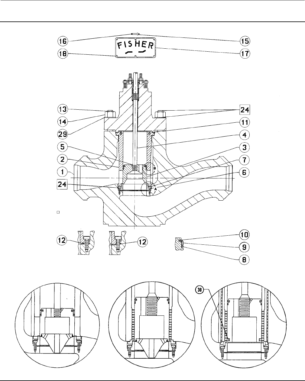
Key numbers referenced in this section are shown in figure12fortheEHDvalveandinfigure14fortheEHTvalve.
EHD and EHT valves are balanced designs. When they are opening or closing, pressure registers on top of the valve
plug (key 3) through the registration holes in the plug. The force of the pressure on top of the plug balances the force
ofthepressureonthebottomoftheplugtoreducetheactuatorforcerequired.
Maintenance
Valve parts are subject to normal wear and must be inspected and replaced as necessary. Inspection and maintenance
frequency depends on the severity of service conditions. This section includes instructions for packing lubrication and
maintenance, trim maintenance, and lapping of metal seats. All maintenance operations can be performed with the
valve in the line.
WARNING
Avoid personal injury from sudden release of process pressure. Before performing any maintenance operations:
DDo not remove the actuator from the valve while the valve is still pressurized.
DAlways wear protective gloves, clothing, and eyewear when performing any maintenance operations to avoid personal
injury.
DDisconnect any operating lines providing air pressure, electric power, or a control signal to the actuator. Be sure the
actuator cannot suddenly open or close the valve.
DUse bypass valves or completely shut off the process to isolate the valve from process pressure. Relieve process pressure
on both sides of the valve. Drain the process media from both sides of the valve.
DVent the power actuator loading pressure and relieve any actuator spring precompression.
DUse lock-out procedures to be sure that the above measures stay in effect while you work on the equipment.
DThe valve packing box may contain process fluids that are pressurized, even when the valve has been removed from the
pipeline. Process fluids may spray out under pressure when removing the packing hardware or packing rings, or when
loosening the packing box pipe plug.
DCheck with your process or safety engineer for any additional measures that must be taken to protect against process
media.
WARNING
Refer to table 4 for valve assembly weights and the appropriate actuator instruction manual for actuator assembly weights.
Due to the size and weight of the valve and actuator assembly, be sure adequately sized hoists and chains or slings are used
to handle it. Also, take proper precautions to prevent personnel from being injured if the hoist or rigging slips
unexpectedly.
Note
Whenever a gasket seal is disturbed by removing or shifting gasketed parts, install a new gasket upon reassembly. This is necessary
to ensure a good gasket seal.
Instruction Manual
D100392X012
EH Valves NPS 8 through 14
July 2014
6
8. After all maintenance is complete, refer to the Trim Replacement procedure to assemble the valve body.
Note
If the valve has ENVIRO-SEAL™ live-loaded packing installed, see the Fisher instruction manual titled ENVIRO-SEAL Packing System
for Sliding-Stem Valves (D101642X012) for packing instructions.
If the valve has HIGH-SEAL live-loaded packing installed, see the Fisher instruction manual titled HIGH-SEAL Live-Loaded Packing
System (D101453X012) for instructions.
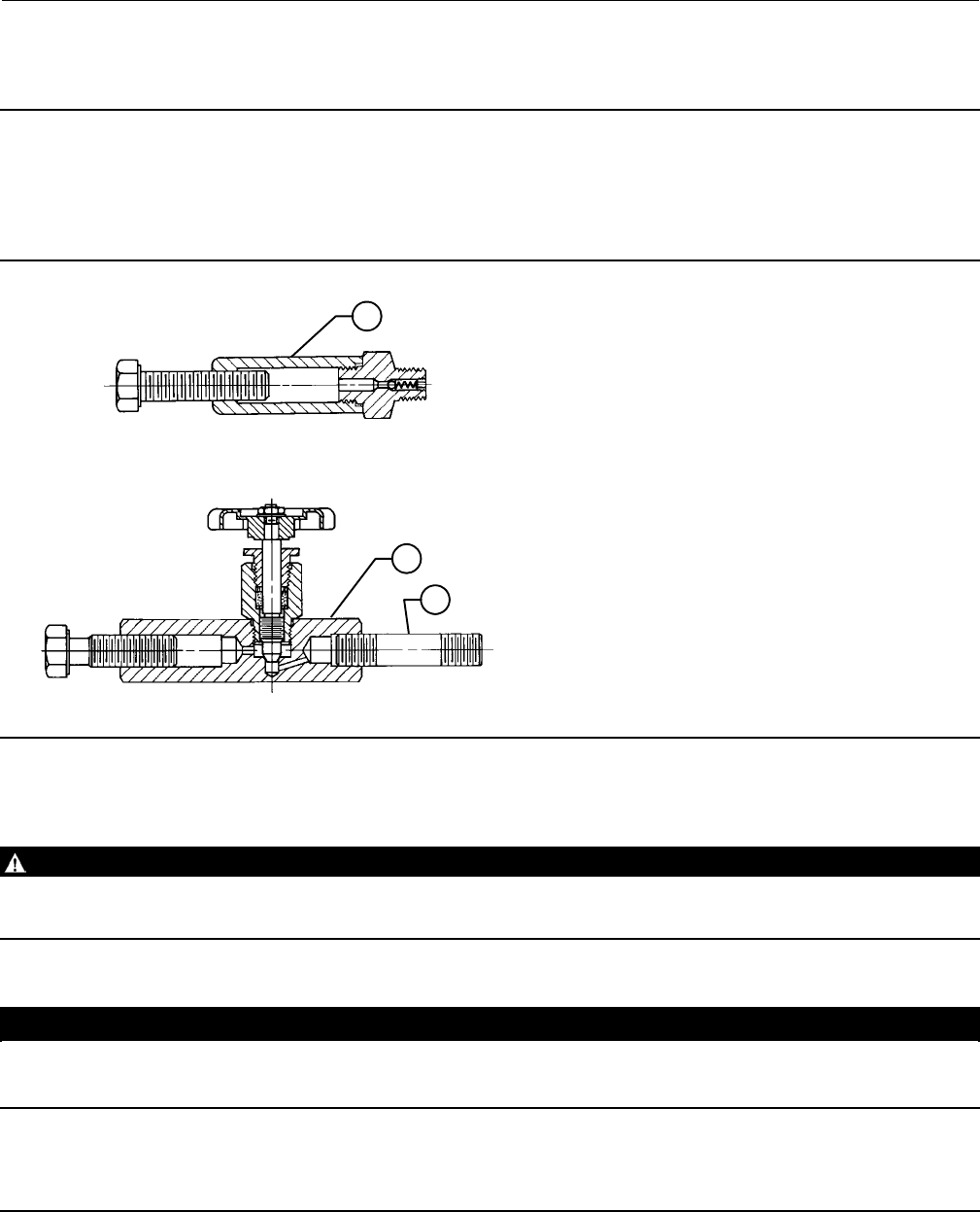
Figure 2. Lubricator and Lubricator/Isolating Valve
LUBRICATOR
LUBRICATOR/ISOLATING VALVE
10A9421-A
AJ5428-D
A0832-2
14
14
27
Packing Lubrication
WARNING
To avoid personal injury or property damage resulting from fire or explosion, do not lubricate packing used in oxygen
service or in processes with temperatures over 260_C (500_F).
CAUTION
Do not lubricate graphite packing. Graphite packing is self-lubricated. Additional lubrication may result in slip-stick
movement of the valve.
Note
ENVIRO-SEAL or HIGH-SEAL packing does not require lubrication.
Instruction Manual
D100392X012
EH Valves NPS 8 through 14
July 2014
7
A lubricator or lubricator/isolating valve (figure 2) is recommended for PTFE-impregnated composition packing. The
lubricator or lubricator/isolating valve is installed in place of the pipe plug in the bonnet. Use a good quality
silicon-base lubricant. Do not lubricate packing used in oxygen service or in processes with temperatures over 260_C
(500_F). To operate the lubricator, turn the cap screw clockwise to force lubricant into the packing box. The
lubricator/isolating valve operates the same way except open the isolating valve before turning the cap screw and then
close the isolating valve after lubrication is completed.
Packing Maintenance
WARNING
Personal injury could result from packing leakage. Valve packing was tightened before shipment; however, the packing
might require readjustment to meet specific service conditions.
Valves with ENVIRO-SEAL live-loaded packing or HIGH-SEAL live-loaded packing installed probably will not require this
initial re-adjustment. See the Fisher instruction manuals titled ENVIRO-SEAL Packing System for Sliding-Stem Valves
(D101642X012) or HIGH-SEAL Live-Loaded Packing System (D101453X012) (as appropriate) for packing instructions.
To convert an existing packing arrangement to ENVIRO-SEAL packing, refer to the retrofit kits listed in the parts kit
sub-section near the end of this manual. Figure 10 shows typical ENVIRO-SEAL packing systems.
For spring-loaded PTFE V-ring packing (figure 4), the spring maintains a sealing force on the packing. If leakage is
noted around the packing follower (key 13, figure 11), check to be sure the shoulder on the packing follower is
touching the bonnet (key 1, figure 11). If the shoulder is not touching the bonnet, tighten the packing flange nuts (key
5, figure 11) until the shoulder on the packing follower is against the bonnet. If the packing leakage is still excessive,
replace the packing by following the Replacing Packing procedure.
If packing leakage is undesirable with other than spring-loaded PTFE V-ring packing, first try to limit the leakage and
establish a stem seal by tightening the packing flange nuts (key 5, figure 11) to at least the minimum recommended
torque in table 5. However, do not exceed the maximum recommended torque in table 5 or excessive friction may
result.
Table 5. Recommended Packing Flange Nut Torques
STEM DIAMETER VALVE
RATING
NSmLbfSft
mm Inches Min Max Min Max
31.8 1-1/4 CL1500 68 102 50 75
CL2500 81 122 60 90
50.8 2CL1500 98 146 72 108
CL2500 115 170 85 125
If the packing is relatively new and tight on the stem, and if tightening the packing flange nuts does not stop the
leakage, the valve stem may be worn or nicked so that a seal cannot be made. The surface finish of a new stem is
critical for making a good packing seal. If the leakage comes from the outside diameter of the packing, the leakage
may be caused by nicks or scratches around the packing box wall. While replacing the packing according to the
Replacing Packing procedure, inspect the stem and packing box wall for nicks or scratches.
Replacing Packing
WARNING
Refer to the WARNING at the beginning of the Maintenance section in this instruction manual.
Instruction Manual
D100392X012
EH Valves NPS 8 through 14
July 2014
8
Key numbers referred to in this procedure are shown in figure 11 unless otherwise indicated.
1. Remove the stem connector cap screws shown in figure 3, and separate the two halves of the stem connector. Then
exhaust all actuator pressure, if any was applied, and disconnect the actuator supply and any leakoff piping.
2. Remove the hex nuts (key 26) and remove the actuator from the bonnet (key 1). Loosen the packing flange nuts
(key 5) so that the packing (key 6, or 7 and 9, figure 4) is not tight on the valve plug stem (key 4, figure 12 or 14).
Remove any travel indicator disk and stem locknuts from the valve plug stem threads.
WARNING
Do not remove a stuck bonnet by pulling on it with equipment that can stretch or store energy in any other manner. The
sudden release of stored energy can cause uncontrolled movement of the bonnet. To avoid personal injury or property
damage caused by uncontrolled movement of the bonnet, loosen the bonnet by following the instructions in the next step.
Figure 3. Actuator Mounting
ANTI-ROTATION GROOVE
TRAVEL INDICATOR
STEM CONNECTOR
POINTER
STEM LOCKNUTS
MOUNTING STUDS & NUTS
STEM
CONNECTOR
CAP SCREWS
15A4691-A
A2359-2
Note
The following step also provides additional assurance that the valve fluid pressure has been relieved.
3. Hex nuts (key 14, figures 12 and 14) attach the bonnet to the valve body. Loosen these nuts approximately 3 mm
(1/8 inch). Then loosen the body-to-bonnet gasketed joint by either rocking the bonnet or prying between the
bonnet and valve body. Work the prying tool around the bonnet until the bonnet loosens. If no fluid leaks from the
joint, proceed with the bonnet removal in step 5.
WARNING
If the cage sticks to the bonnet, proceed carefully with bonnet removal until the cage windows are accessible. Do not
extend hands or arms through the windows at this point as a sudden separation of bonnet and cage will cause personal

Instruction Manual
D100392X012
EH Valves NPS 8 through 14
July 2014
9
injury. Use a stick or other device to thread a rope or sling through the windows. Use this rigging to secure the cage to the
bonnet or hoist to prevent damage or injury should the cage suddenly separate from the bonnet.
CAUTION
When lifting the bonnet (key 1), be sure that the valve plug and stem assembly (keys 3 and 4, figure 12 or 14) remains on
the seat ring (key 6, figure 12 or 14). This avoids damage to the seating surfaces as a result of the assembly dropping from
the bonnet after being lifted part way out. The parts are also easier to handle separately.
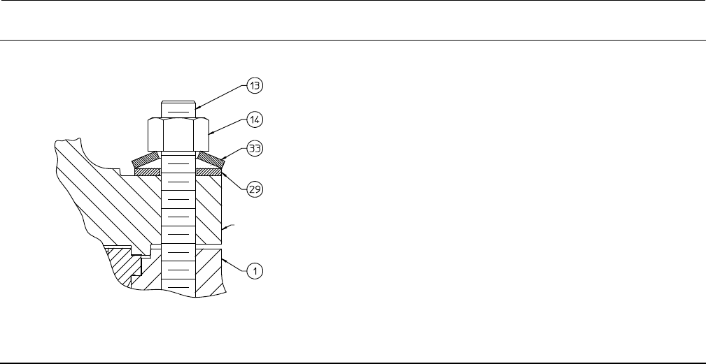
4. Remove the hex nuts (key 14, figure 12 or 14) and washers (key 29 and 33, figure 12, 13, or 14). Carefully lift the
bonnet off the valve plug stem. If the valve plug assembly starts to lift with the bonnet, use a brass or similar
hammer to tap the end of the stem and tap it back down. Set the bonnet on a protective surface to prevent damage
to the bonnet gasket surface.
CAUTION
Use care to avoid damaging gasket sealing surfaces.
EHD piston rings (key 8) are brittle and in two halves. Use care to avoid damage to the piston rings caused by dropping or
rough handling.
5. Lifttheplugassembly(keys3and4,figure12or14)outofthevalvebody.
6. To remove the cage (key 2, figure 12 or 14), if it remained in the valve body, install eyebolts or similar devices into
the 1/2 inch 13-UNC tapped holes in the top of the cage. Using the eyebolts, carefully lift the cage out of the valve
body. Remove the top and bottom cage gaskets (key 11, figure 12 or 14). Carefully remove any residual silver or tin
from the gasket surfaces.
7. Cover the opening in the valve body to protect the gasket surface and to prevent foreign material from getting into
the valve body cavity.
Table 6. Body-to-Bonnet Bolting Torques
VALVE SIZE
NPS
VALVE
RATING
B7,B16,BD,660STUDS B8, B8M STUDS
NSmlbfSft NSmlbfSft
8, 10 CL1500 2710 2000 2035 1500
CL2500 4070 3000 3050 2250
12, 14 CL1500 8130 6000 6100 4500
CL2500 5830 4300 4370 3225
8. Remove the packing flange nuts, packing flange, upper wiper and packing follower. Carefully push out all the
remaining packing parts from the valve side of the bonnet using a rounded rod or other tool that will not scratch the
packing box wall. Clean the packing box and these metal packing parts shown in the figure 4 arrangements: packing
box ring, spring, lantern ring, washer if used, and packing follower (keys 11, 8, 10, and 13).
9. Inspect the valve plug stem threads for any sharp edges that might cut the packing. Use a whetstone or emery cloth
to smooth the threads if necessary.
10. Remove the protective covering from the valve body cavity, and install the cage using new cage gaskets (key 11,
figure 12 or 14).
11. Install the plug and stem assembly. Be sure the seal ring or piston rings are installed correctly as described under
Trim Replacement.
Instruction Manual
D100392X012
EH Valves NPS 8 through 14
July 2014
10
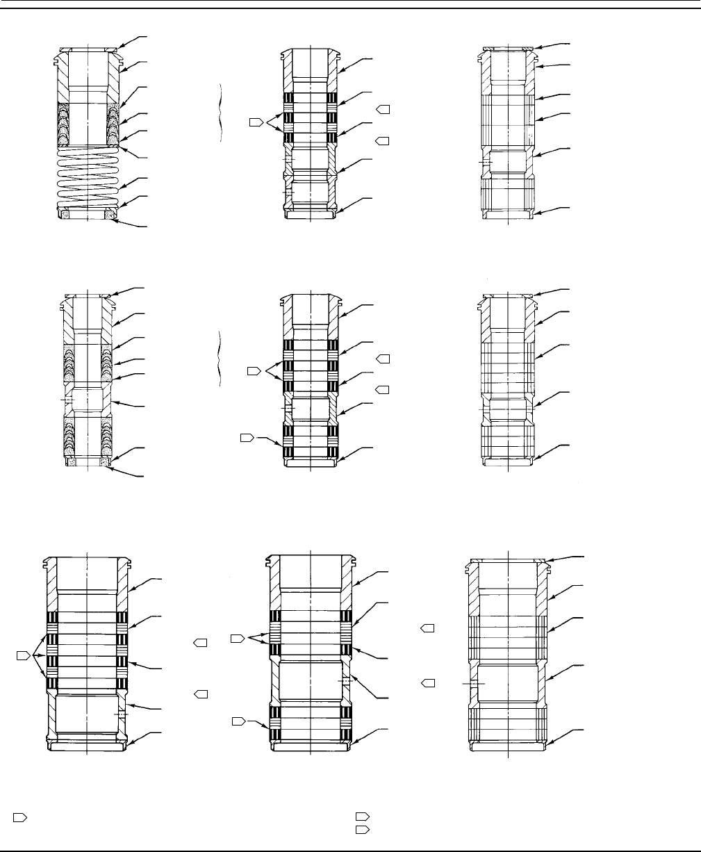
Figure 4. Packing Arrangements
GRAPHITE
LAMINATE
PACKING RING
(KEY 7)
UPPER WIPER (KEY 12) UPPER WIPER (KEY 12)
PACKING FOLLOWER
(KEY 13)
FEMALE
ADAPTOR
(KEY 32)
V-RING (KEY 7)
MALE ADAPTOR
(KEY 31)
WASHER (KEY 10)
SPRING (KEY 8)
PACKING BOX
RING (KEY 11)
LOWER WIPER
(KEY 30)
KEY 6
1
2
PACKING FOLLOWER
(KEY 13)
GRAPHITE LAMINATE
PACKING RING (KEY 7)
GRAPHITE FILAMENT
PACKING RING (KEY 9)
LANTERN RING
(KEY 8)
PACKING BOX RING
(KEY 11)
3
PACKING FOLLOWER
(KEY 13)
PACKING RING
(KEY 7)
PACKING RING
(KEY 7)
LANTERN RING
(KEY 8)
PACKING BOX RING
(KEY 11)
12A8160-A 14A3412-B 13A0112-A
PTFE V-RING
SINGLE PACKING
GRAPHITE LAMINATE AND FILAMENT
SINGLE PACKING
GRAPHITE/COMPOSITION
DOUBLE PACKING
UPPER WIPER (KEY 12) UPPER WIPER (KEY 12)
PACKING FOLLOWER
(KEY 13)
FEMALE ADAPTOR
(KEY 32)
V-RING (KEY 7)
MALE ADAPTOR
(KEY 31)
LANTERN RING
(KEY 8)
PACKING BOX
RING (KEY 11)
LOWER WIPER (KEY
30)
KEY 6
1
2
PACKING FOLLOWER
(KEY 13)
GRAPHITE LAMINATE
PACKING RING (KEY 7)
GRAPHITE FILAMENT
PACKING RING (KEY 9)
LANTERN RING
(KEY 8)
PACKING BOX RING
(KEY 11)
3
PACKING FOLLOWER
(KEY 13)
PACKING RING
(KEY 7)
LANTERN RING
(KEY 8)
PACKING BOX RING
(KEY 11)
12A7839-A
Sht 1 14A3414-B 12A8163-A
PTFE V-RING
DOUBLE PACKING
GRAPHITE LAMINATE AND FILAMENT
DOUBLE PACKING
PTFE/COMPOSITION
DOUBLE PACKING
UPPER WIPER (KEY 12)
PACKING FOLLOWER
(KEY 13)
PACKING RING
(KEY 7)
LANTERN RING
(KEY 8)
PACKING BOX RING
(KEY 11)
1
2
PACKING
FOLLOWER
(KEY 13)
GRAPHITE
FILAMENT
PACKING RING
(KEY 9)
LANTERN RING
(KEY 8)
PACKING
BOX RING
(KEY 11)
3
1
1
14A3419-B 14A3418-A 13A0029-A
1
GRAPHITE
LAMINATE
PACKING RING
(KEY 7) 2
PACKING
FOLLOWER (KEY 13)
GRAPHITE FILAMENT
PACKING RING
(KEY 9)
LANTERN RING
(KEY 8)
PACKING
BOX RING (KEY 11)
3
GRAPHITE LAMINATE AND FILAMENT
SINGLE PACKING
GRAPHITE LAMINATE AND FILAMENT
DOUBLE PACKING
GRAPHITE/COMPOSITION AND PTFE/COMPOSITION
DOUBLE PACKING
PACKING ARRANGEMENTS FOR 31.8 mm (1-1/4 INCH) VALVE STEMS
PACKING ARRANGEMENTS FOR 50.8 mm (2-INCH) VALVE STEMS
NOTES:
0.102 mm (0.004 INCH) THICK SACRIFICIAL ZINC WASHERS.
USE ONLY ONE BELOW EACH GRAPHITE LAMINATE RING.
HAS THE APPEARANCE OF FLAT WASHERS PRESSED TOGETHER.
HAS THE APPEARANCE OF A WOVEN OR BRAIDED RING.
12
3
C0634-1

Instruction Manual
D100392X012
EH Valves NPS 8 through 14
July 2014
11
12. Slide the bonnet over the stem and onto the bonnet studs (key 13, figure 12 or 14).
Note
Proper performance of the bolting procedures in step 13 compresses the cage gaskets (key 11, figure 12 or 14) enough to seal the
body-to-bonnet joint.
The prelubricated hex nuts (key 14, figure 12 or 14) referred to in step 13 can be identified by a black film coating on the nut
threads.
The proper bolting procedures in step 13 include, but are not limited to, ensuring that the bonnet stud threads are clean, Belleville
washers (if present) are installed in the correct orientation, and that the hex nuts are evenly tightened to the specified torque
values.
CAUTION
Failure to comply with good bonnet-to-body bolting practices and the torque values shown in table 6 may result in cage
crushing, cage diameter reduction, and/or bonnet deformation. Do not use cheater bars or slug wrenches for this
procedure.
Hottorquingisnotrecommended;itmayresult in damage to valve components.
Note
Stud(s) and nut(s) should be installed such that the manufacturer's trademark and material grade marking is visible, allowing easy
comparison to the materials selected and documented in the Emerson/Fisher serial card provided with this product.
WARNING
Personal injury or damage to equipment could occur if improper stud and nut materials or parts are used. Do not operate or
assemble this product with stud(s) and nut(s) that are not approved by Emerson/Fisher engineering and/or listed on the
serial card provided with this product. Use of unapproved materials and parts could lead to stresses exceeding the design
or code limits intended for this particular service. Install studs with the material grade and manufacturer's identification
mark visible. Contact your Emerson Process Management representative immediately if a discrepancy between actual
parts and approved parts is suspected.
13. Lubricate the stud threads and the faces of the hex nuts (key 14, figure 12 or 14) with anti-seize lubricant (not
necessary if new factory prelubricated hex nuts are used). Replace the flat washers (key 29, figure 12 or 14) and
Belleville washers (key 33, figure 13), if included with the valve body assembly. Belleville washers must be installed
so that the concave side is facing towards the valve body or flat washer. Replace the hex nuts and torque the nuts in
a crisscross pattern to no more than 1/4 of the nominal torque value specified in table 6. When all nuts are
tightened to that torque value, increase the torque by 1/4 of the specified nominal torque and repeat the crisscross
pattern. Repeat this procedure until all nuts are tightened to the specified nominal value. Apply the final torque
value again and, if any nut still turns, tighten every nut again.
14. Install new packing and the metal packing box parts according to the appropriate arrangement in figure 4. Slip a
smooth-edged pipe over the valve stem, and gently tamp each soft packing part into the packing box.
15. Slide the packing follower, wiper, and packing flange into position. Lubricate the packing flange studs (key 4) and
the faces of the packing flange nuts (key 5) and then install the packing flange nuts.
Instruction Manual
D100392X012
EH Valves NPS 8 through 14
July 2014
12
For spring-loaded PTFE V-ring packing: Tighten the packing flange nuts until the shoulder on the packing follower (key
13) contacts the bonnet (key 1).
For other kinds of packing, except ENVIRO-SEAL and HIGH-SEAL: Tighten the packing flange nuts to the maximum
recommended torque shown in table 5. Then, loosen the packing flange nuts and retighten them to the
recommended minimum torque in table 5.
For ENVIRO-SEAL and HIGH-SEAL packing: See the Fisher instruction manuals titled ENVIRO-SEAL Packing System for
Sliding-Stem Valves (D101642X012) or HIGH-SEAL Live-Loaded Packing System (D101453X012) (as appropriate) for
packing instructions.
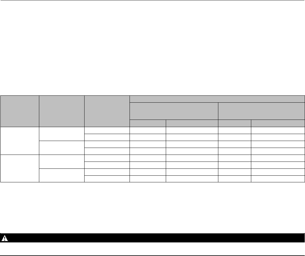
Table 7. Seat Ring and Seat Ring Cap Screw Lubricants and Recommended Torque for Seat Ring Cap Screws
LUBRICANT
VALVE
SIZE,
NPS
VALVE
RATING
RECOMMENDED TORQUE
Spiral Wound
Gasket Construction
O-Ring Construction or
Constructions for
Sour Gas Service
NSmlbfSft NSmlbfSft
Lithium Grease
or Anti-Seize
Lubricant
8, 10 CL1500 61 45 41 30
CL2500 95 70 61 45
12, 14 CL1500 95 70 61 45
CL2500 95 70 61 45
Dry Film
Lubricant
8, 10 CL1500 47 35 34 25
CL2500 75 55 47 35
12, 14 CL1500 75 55 47 35
CL2500 75 55 47 35
16. Mount the actuator on the valve body assembly, and reconnect the actuator and valve plug stem according to the
Actuator Mounting procedure. After the control valve is returned to service, retighten the hex nuts (key 14, figure
12 or 14) to the torque recommended in table 6.
Trim Removal
WARNING
Refer to the WARNING at the beginning of the Maintenance section in this instruction manual.
For Bore seal construction, see the appropriate Bore seal sections in this instruction manual.
Key numbers referenced in this procedure are shown in figure 12 for the EHD valve and figure 14 for the EHT valve
except where indicated.
1. Remove the actuator and bonnet by following steps 1 through 9 of the Replacing Packing procedure.
2. To remove the seat ring (key 6), remove the cap screws (key 7). Install eyebolts or similar devices in the 5/8 inch
11-UNC tapped holes (9/16 inch 12-UNC for an NPS 8 or 10 CL1500 valve). Use the eyebolts to carefully lift the seat
ring out of the valve body. If the seat ring is to be reused, exercise care to protect the gasket surfaces on the bottom
of the seat ring.
3. Remove the spiral wound seat ring gasket or O-ring (key 12).
4. Refer to the following appropriate valve plug maintenance procedure or to the Lapping Seats procedure.
EHD and EHT Valve Plug Maintenance
Key numbers used in this procedure are shown in figure 12 for the EHD valve and in figure 14 for the EHT valve.

Instruction Manual
D100392X012
EH Valves NPS 8 through 14
July 2014
13
1. With the valve plug (key 3) removed per the Trim Removal procedure, proceed as appropriate:
For the EHD valve, the piston rings (key 8) are each in two sections; remove the sections from the grooves in the valve
plug.
For all EHT valves, work the retaining ring (key 10) off the valve plug with a screwdriver. Carefully slide the backup ring
and seal ring (keys 9 and 8) off the valve plug. Additionally, for the EHT valve with Whisper Trim Level D cage, remove
the two sections of the piston ring (key 30, figure 14).
2. Toreplacethevalveplugstem(key4),driveoutthepin(key5)andunscrewthestemfromthevalveplug(key3).
CAUTION
Never reuse an old stem with a new valve plug. Using an old stem with a new plug requires drilling a new pin hole in the
stem. This weakens the stem and may cause the stem to fail in service. If a new valve plug is required, always order a valve
plug, stem, and pin as an assembly. Specify the correct part number of each of the three parts but state that the parts are
being ordered as an assembly.
A used valve plug may be reused with a new stem.
3. Thread the new stem into the valve plug until the stem wedges tightly at the end of the thread. Using the valve plug
pin hole as a guide, drill the pin hole through the stem. Use a 1/4 inch drill for 31.8 mm (1-1/4 inch) stems and a 3/8
inch drill for 50.8 mm (2-inch) stems.
4. Drive in the pin to lock the assembly.
5. If seat lapping is necessary, complete the Lapping Seats procedure before installing the EHD piston rings or the EHT
seal ring. Piston ring and seal ring installation instructions and valve body-to-bonnet reassembly instructions are
presented in the Trim Replacement procedure.
Lapping Seats
Key numbers referenced in this procedure are shown in figure 12 for the EHD valve and in figure 14 for the EHT valve.
A certain amount of leakage should be expected with metal-to-metal seating in any valve. If the leakage becomes
excessive, however, the condition of the seating surfaces of the valve plug (key 3) and seat ring (key 6) can be
improved by lapping. (Deep nicks should be machined out rather than ground out.) Use a good quality lapping
compound with a mixture that contains 280 to 600 grit. Apply the compound to the bottom of the valve plug.
Use the following procedure to lap the seating surfaces.
1. For all designs, install the seat ring gasket or O-ring (key 12), seat ring (key 6), seat ring cap screws (key 7), lower
cage gasket (key 12), cage (key 2), and upper cage gasket (key 12) into the valve body per the instructions in the
Trim Replacement procedure.
2. Install the assembled valve plug and stem (keys 3 and 4)--without piston rings or seal ring (key 8)-- into the cage.
3. For all seating surfaces, install the bonnet (key 1, figure 11) over the valve stem and secure the bonnet with four of
the hex nuts (key 14).
4. Attach a handle, such as a piece of strap iron secured by stem locknuts, to the valve plug stem. Rotate the handle
alternately in each direction to lap the seats.
Note
In order to preserve the effects of lapping, do not change either the position of the seat ring in the valve body cavity or the position
of the cage on the seat ring after lapping the seating surfaces. If possible, clean the parts without disturbing their positions. If the
parts must be removed for cleaning, return them to the original positions.

Instruction Manual
D100392X012
EH Valves NPS 8 through 14
July 2014
14
5. After lapping, again disassemble as necessary, clean the seating surfaces, reassemble, and test for shutoff. Repeat
the lapping procedure if necessary.
Trim Replacement
After all trim maintenance has been completed, reassemble the valve by following the numbered steps below. Be
certain that all gasketed surfaces are clean. Key numbers referenced in this procedure are shown in figure 12 for the
EHD valve and in figure 14 for the EHT valve.
CAUTION
Thoroughly clean the seat ring (key 6), the seat ring cap screws (key 7), and the cap screw threads in the valve body with a
good-quality degreaser. Unless the valve is to be used for oxygen service, thoroughly lubricate the cap screw threads and
the underside of the cap screw heads with one of the lubricants (or equivalent) shown in table 7.
Failure to lubricate as described may cause galling and improper seat ring gasket or O-ring (key 12) loading which may
result in leakage.
WARNING
If the control valve is to be used for oxygen service, use the lubrication procedure above, but substitute a lubricant that has
been approved for oxygen service. Use of unapproved lubricants creates a fire or explosion hazard.
1. Install either the seat ring gasket or the O-ring (key 12). Place the O-ring in the O-ring groove in the seat ring before
installing the seat ring in the valve body. Install the seat ring (key 6) and secure it with the seat ring cap screws (key
7). Torque the hex socket head cap screws in a criss-cross pattern with no more than 20 NSm(15lbfSft) of torque.
When all are tightened to 20 NSm(15lbfSft),increasethetorque20NSm(15lbfSft) without exceeding the torque
valuespecifiedintable7,andrepeatthecrisscrosspattern. Repeat until all cap screws are tightened to the torque
value specified in table 7. Repeat the final torque and if any cap screw still turns, tighten every cap screw again.
2. Install one of the cage gaskets (key 11) between the valve body and cage (key 2), and install the cage.
3. If the cage used has multiple sizes of windows, attempt to orient the largest window toward the valve body web (a
shelf-like projection of the casting into the flow cavity). As an alternate reference, orient the largest window toward
the process outlet for a flow-down and toward the process inlet for a flow-up valve.
4. Inspect the valve plug stem threads for any sharp edges that might cut the packing. Use a whetstone or emery cloth
to smooth the threads if necessary.
5. To install the piston rings or seal ring (key 8), proceed as appropriate:
For an EHD valve, if installing a new piston ring, the replacement piston ring will arrive in one piece. Use a vise with
smooth or taped jaws to break this replacement piston ring into halves. Place the new ring in the vise so that the jaws
compress the ring into an oval. Slowly compress the ring until the ring snaps on both sides. If one side snaps first, do
not try to tear or cut the other side. Instead, keep compressing until the other side snaps.
Remove any protective tape or covering from the valve plug and stem assembly, and set it on a protective surface.
Then place the piston ring in the piston ring groove with the fractured ends matched.
For an EHT valve, install the seal ring (key 8) onto the valve plug (key 3). Install the ring with the open side facing the
seat ring end of the valve plug for a flow-down application (view B of figure 14) or with the open side facing the valve
stem end of the valve plug for a flow-up application. Slide the backup ring (key 9) onto the valve plug. Secure with the
retaining ring (key 10). For an EHT valve with a Whisper Trim Level D cage, install the piston ring (key 30, figure 14)
using the procedure given in the EHD instructions immediately preceding this paragraph.

Instruction Manual
D100392X012
EH Valves NPS 8 through 14
July 2014
15
6. Install the valve plug into the cage.
7. Install the other cage gasket (key 11) between the cage and the bonnet.
CAUTION
Failure to comply with good bonnet-to-body bolting practices and the torque values shown in table 6 may result in cage
crushing, cage diameter reduction, and/or bonnet deformation. Cheater bars or slug wrenches should not be used for this
procedure.
Hottorquingisnotrecommended;itmayresult in damage to valve components.
Note
Stud(s) and nut(s) should be installed such that the manufacturer's trademark and material grade marking is visible, allowing easy
comparison to the materials selected and documented in the Emerson/Fisher serial card provided with this product.
WARNING
Personal injury or damage to equipment could occur if improper stud and nut materials or parts are used. Do not operate or
assemble this product with stud(s) and nut(s) that are not approved by Emerson/Fisher engineering and/or listed on the
serial card provided with this product. Use of unapproved materials and parts could lead to stresses exceeding the design
or code limits intended for this particular service. Install studs with the material grade and manufacturer's identification
mark visible. Contact your Emerson Process Management representative immediately if a discrepancy between actual
parts and approved parts is suspected.
8. Install the bonnet over the valve stem and onto the valve body. Lubricate the threads of the studs (key 13) and the
faces of the hex nuts (key 14) with anti-seize lubricant (key 24). Secure the bonnet with hex nuts (key 14) and
washers(key29).Torquethenutsinacrisscrosspatterntonomorethan1/4ofthenominaltorquevaluespecified
intable6.Whenallnutsaretightenedtothattorquevalue,increasethetorqueby1/4ofthespecifiedtorquevalue
and repeat the crisscross pattern. Repeat this procedure until all nuts are tightened to the specified nominal value.
Repeat the final torque value and if any nut still turns, tighten every nut again.
9. Install new packing and the metal packing box parts according to the appropriate arrangement in figure 4. Slip a
smooth-edged pipe over the valve stem, and gently tamp each soft packing part into the packing box.
10. Slide the packing follower, wiper, and packing flange into position. Lubricate the packing flange studs (key 4) and
the faces of the packing flange nuts (key 5) and then install the packing flange nuts.
For spring-loaded PTFE V-ring packing: Tighten the packing flange nuts until the shoulder on the packing follower (key
13) contacts the bonnet (key 1).
For other kinds of packing, except ENVIRO-SEAL and HIGH-SEAL: Tighten the packing flange nuts to the maximum
recommended torque shown in table 5. Then, loosen the packing flange nuts and retighten them to the
recommended minimum torque in table 5.
For ENVIRO-SEAL and HIGH-SEAL packing: See the Fisher instruction manuals titled ENVIRO-SEAL Packing System for
Sliding-Stem Valves (D101643X012) or HIGH-SEAL Live-Loaded Packing System (D102453X012) (as appropriate) for
packing instructions.
11. Mount the actuator by following the Actuator Mounting procedure. Check for packing leakage as the valve is
being put into service. Retorque the packing flange nuts as required (see table 5). Then, retighten the hex nuts (key
14)tothetorqueshownintable6.
Instruction Manual
D100392X012
EH Valves NPS 8 through 14
July 2014
16
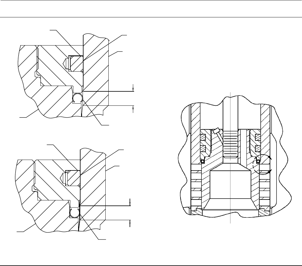
Figure 5. Fisher EHD with Bore Seal Trim
FLOW DOWN
FLOW UP
PLUG
RETAINER
BORE SEAL
PISTON RING
CAGE
RETAINER
CAGE
BORE SEAL
PLUG
SEATING AREA
PISTON RING
SEATING AREA
A
VIEW A

Instruction Manual
D100392X012
EH Valves NPS 8 through 14
July 2014
17
Retrofit: Installing Bore Seal Trim
Note
Additional actuator thrust is required for a valve with Bore Seal trim. When installing Bore Seal trim in an existing valve, contact
your Emerson Process Management sales office for assistance in determining new actuator thrust requirements.
Assemble the new valve plug/retainer assembly (with Bore Seal plug seal) using the following instructions:
CAUTION
To avoid leakage when the valve is returned to service, use appropriate methods and materials to protect all sealing
surfaces of the new trim parts while assembling the individual parts and during installation in the valve body.
1. Apply a suitable high-temperature lubricant to the inside diameter of the Bore Seal plugseal.Also,lubricatethe
outside diameter of the valve plug where the Bore Seal plug seal must be pressed into the proper sealing position
(figure 5).
2. OrienttheBoreSealplugsealforcorrect sealing action based on the process fluid flow direction through the valve.
DThe open interior of the Bore Seal plug seal must face up in a valve with flow-up construction (figure 5).
DThe open interior of the Bore Seal plug seal must face down in a valve with flow-down construction (figure 5).
3. Place the Bore Seal plug seal over the top of the valve plug. The retainer will help guide the Bore Seal down onto the
plug (figure 5). Do not force the Bore Seal over the plug. For flow down constructions, skip to step 5.
4. An installation tool (see table 8) must be inserted into the Bore Seal prior to using the retainer to guide it down the
plug.
5. Apply a suitable high-temperature lubricant to the threads on the plug. Then, place the Bore Seal retainer onto the
plug and tighten the retainer using an appropriate tool such as a strap wrench. For flow down constructions, skip to
step 7.
6. Remove the retainer and then the installation tool. Place the Bore Seal retainer back onto the plug and tighten the
retainer using an appropriate tool such as a strap wrench.
7. Using an appropriate tool such as a center punch, stake the threads on top of the plug in one place (figure 7) to
secure the Bore Seal retainer.
8. Install the new plug/retainer assembly with Bore Seal plug seal on the new stem following the appropriate
instructions in the Trim Replacement section of this manual.
9. Install piston rings by following instructions in the Trim Replacement section of this manual.
10. Remove the existing valve actuator and bonnet following the appropriate instructions in the Replacing Packing
section of this manual.
Instruction Manual
D100392X012
EH Valves NPS 8 through 14
July 2014
18
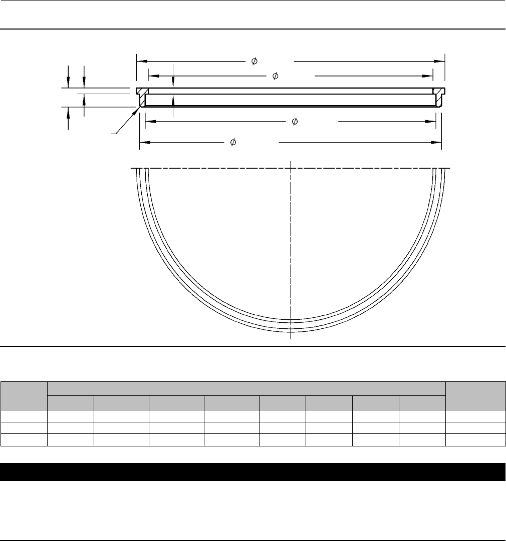
Figure 6. Bore Seal Installation Tool
GE22109-A
A
B
C
D
E
F
G
H
Table 8. Bore Seal Installation Tool Dimensions
VALVE
PORT SIZE,
INCH
Dimensions, Inches (See Figure 6) Tool Part
Number
A B C D E F G H
5.375 5.49 5.07 5.17-5.19 5.39-5.37 0.10 0.10 0.32 R.06 GE22109X012
7.00 7.11 6.69 6.79-6.81 7.01-6.99 0.09 0.10 0.32 R.06 GE18264X012
10.00 10.12 9.7 9.80-9.82 10.02-10.00 0.10 0.10 0.32 R.06 GE17914X012
CAUTION
Do not remove the existing valve stem from the valve plug unless you are planning to replace the valve stem.
Never reuse an old valve stem with a new plug or reinstall a valve stem after it has been removed. Replacing a valve stem
requires drilling a new pin hole in the stem. This drilling weakens the stem and may cause failure in service. However, a
used valve plug may be reused with a new valve stem.
11. Removetheexistingvalvestemandplug,cage,andseatringfromthevalvebodyfollowingtheappropriate
instructions in the Trim Removal section of this manual.
12. Replace all gaskets according to appropriate instructions in the Trim Replacement section of this manual.
13. Install the new seat ring, cage, valve plug/retainer assembly, and stem into the valve body and completely
reassemble the valve package following the appropriate instructions in the Trim Replacement section of this
manual.

Instruction Manual
D100392X012
EH Valves NPS 8 through 14
July 2014
19
CAUTION
To avoid excessive leakage and seat erosion, the valve plug must be initially seated with sufficient force to overcome the
resistance of the Bore Seal plug seal and contact the seat ring. You can correctly seat the valve plug by using the same force
calculated for full load when sizing your actuator. With no pressure drop across the valve, this force will adequately drive
the valve plug to the seat ring, thus giving the Bore Seal plug seal a predetermined permanent set. Once this is done, the
plug/retainer assembly, the cage, and the seat ring become a matched set.
With full actuator force applied and the valve plug fully seated, align the actuator travel indicator scale with the lower end
of valve travel. Refer to the appropriate actuator instruction manual for information on this procedure.
Replacement of Installed Bore Seal Trim
Trim Removal (Bore Seal Constructions)
1. Remove the valve actuator and bonnet following the appropriate instructions in the Replacing Packing section of
this manual.
CAUTION
To avoid leakage when the valve is returned to service, use appropriate methods and materials to protect all sealing
surfaces of the trim parts during maintenance.
Use caution when removing piston ring(s) and the Bore Seal plug seal to avoid scratching any sealing surface.
CAUTION
Do not remove the valve stem from the plug/retainer assembly unless you are planning to replace the valve stem.
Never reuse an old valve stem with a new plug or reinstall a valve stem after it has been removed. Replacing a valve stem
requires drilling a new pin hole in the stem. This drilling weakens the stem and may cause failure in service. However, a
used valve plug may be reused with a new valve stem.
2. Remove the plug/retainer assembly (with Bore Seal plug seal), cage, and seat ring from the valve body following the
appropriate instructions in the Trim Removal section of this manual.
3. Locatethestakedthreadontopofthevalveplug(figure7).Thestakedthreadsecurestheretainer.Useadrillwitha
1/8 inch bit to drill out the staked area of the thread. Drill approximately 1/8 inch into the metal to remove the
staking.
4. Locate the break between sections of the piston ring(s). Using an appropriate tool such as a flat-blade screwdriver,
carefully pry out the piston ring(s) from the groove(s) in the Bore Seal retainer.
5. After removing the piston ring(s), locate the 1/4-inch diameter hole in the groove. In a retainer with two piston ring
grooves,theholewillbefoundintheuppergroove.
6. Selectanappropriatetoolsuchasapunchandplacethetipofthetoolintotheholewiththebodyofthetoolheld
tangent to the outside diameter of the retainer. Strike the tool with a hammer to rotate the retainer and free it from
thevalveplug.Removetheretainerfromtheplug.
Instruction Manual
D100392X012
EH Valves NPS 8 through 14
July 2014
20
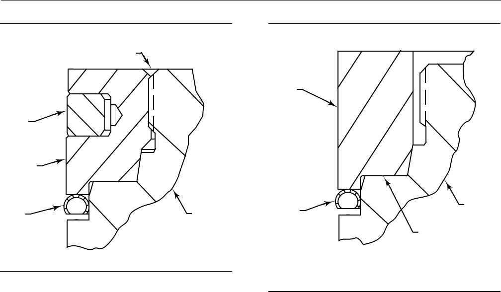
Figure7.StaketheThreadsoftheBoreSealRetainer
Bore Seal
METAL
PLUG
SEAL
VALVE
PLUG
FLOW DOWN
PISTON
RING
RETAINER
DEFORM THREAD TO
STAKE Bore Seal RETAINER
A6779
Figure8.InstallingtheBoreSealPlugSeal
Using the Installation Tool
Bore Seal
METAL
PLUG
SEAL
INSTALLATION
TOOL
A6778
VALVE
PLUG
HORIZONTAL
REFERENCE
SURFACE
FLOW DOWN
NOTE: PRESS THE INSTALLATION TOOL OVER THE VALVE PLUG UNTIL THE TOOL
CONTACTS THE HORIZONTAL REFERENCE SURFACE OF THE VALVE PLUG.
7. Use an appropriate tool such as a flat-blade screwdriver to pry the Bore Seal plug seal off the plug. Use caution to
avoid scratches or other damage to the sealing surfaces where the Bore Seal plug seal makes contact with the valve
plug (figure 9).
8. Inspect the lower seating surface where the valve plug contacts the seat ring for wear or damage which would
prevent proper operation of the valve. Also, inspect the upperseatingsurfaceinsidethecagewheretheBoreSeal
plugsealcontactsthecage,andinspectthesealingsurfacewheretheBoreSealplugsealmakescontactwiththe
plug (figure 9).
9. Replace or repair trim parts according to the following procedure for lapping metal seats, remachining metal seats,
or other valve plug maintenance procedures as appropriate.
Lapping Metal Seats (Bore Seal Constructions)
Before installing a new Bore Seal plug seal, lap the lower seating surface (valve plug to seat ring, figure 9) following
appropriate procedures in the Lapping Seats section of this manual.
Remachining Metal Seats (Bore Seal Constructions)
A valve plug with a Bore Seal metal plug seal features two seating surfaces. One seating surface is found where the
valveplugcontactstheseatring.ThesecondseatingsurfaceisfoundwheretheBoreSealplugsealcontactstheupper
seatingsurfaceinthecage.Thecagedoesnotrequireanymachining, even when the plug and / or seat ring have been
machined.
Trim Replacement (Bore Seal Constructions)
1. Apply a suitable high-temperature lubricant to the inside diameter of the Bore Seal plugseal.Also,lubricatethe
outside diameter of the valve plug where the Bore Seal plug seal must be pressed into the proper sealing position
(figure 5).
2. OrienttheBoreSealplugsealforcorrect sealing action based on the process fluid flow direction through the valve.
Instruction Manual
D100392X012
EH Valves NPS 8 through 14
July 2014
21
DThe open interior of the Bore Seal plug seal must face up in a valve with flow-up construction (figure 5).
DThe open interior of the Bore Seal plug seal must face down in a valve with flow-down construction (figure 5).
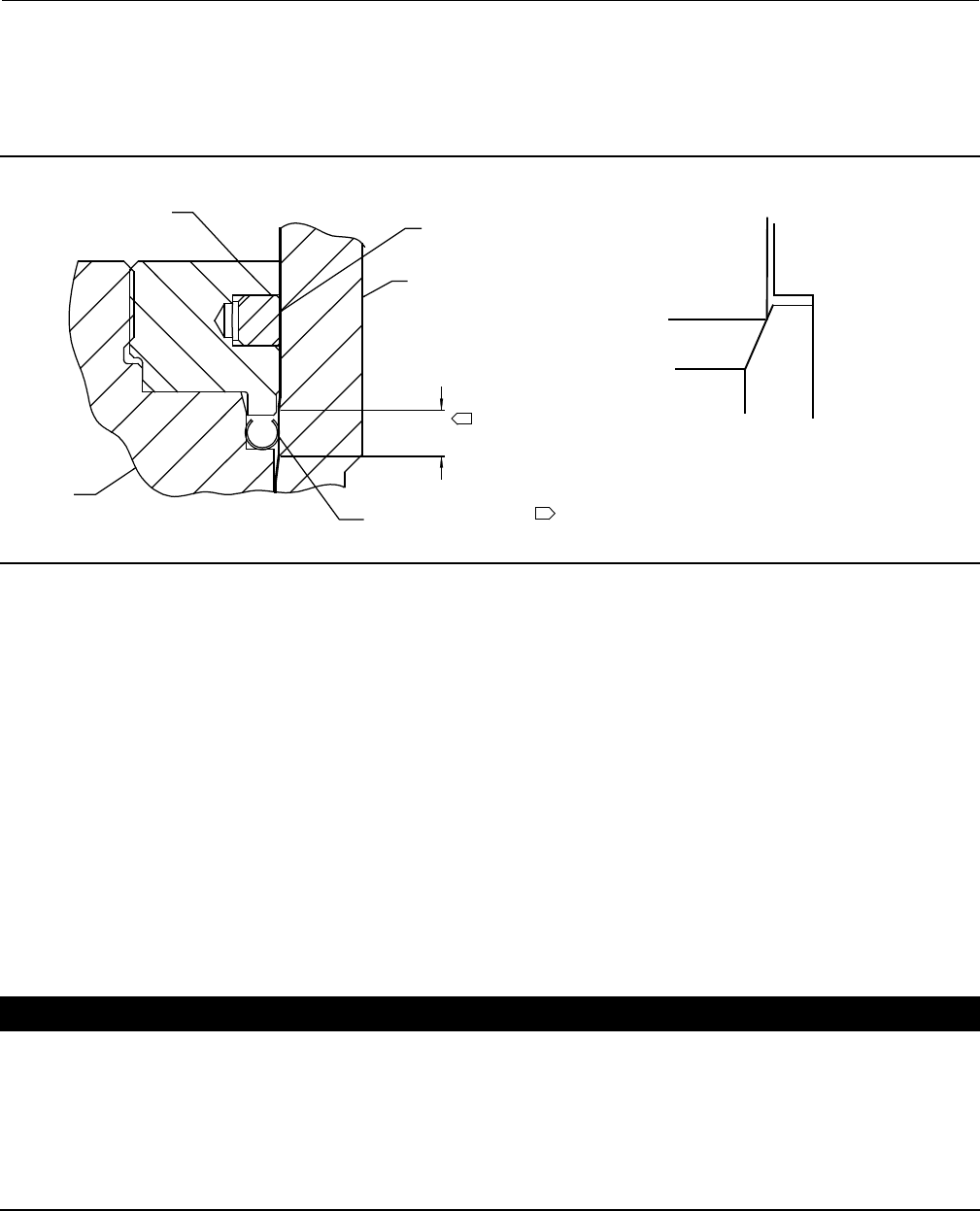
Figure 9. Lower (Valve Plug to Seat Ring) and Upper (Bore Seal Plug Seal to Cage) Seating Surfaces
NOTE:
UPPER SEATING SURFACE IS THE AREA OF CONTACT BETWEEN THE
BORE SEAL METAL PLUG SEAL AND THE CAGE.
PLUG
CAGE
SEAT
RING
UPPER SEATING SURFACE
LOWER SEATING SURFACE
A6780
1
1
PISTON
RING
RETAINER
CAGE
BORE SEAL
PLUG
SEATING AREA
3. Place the Bore Seal plug seal over the top of the valve plug. The retainer will help guide the Bore Seal down onto the
plug. Do not force the Bore Seal over the plug. For flow down constructions, skip to step 5.
4. An installation tool (see table 8) must be inserted into the Bore Seal prior to using the retainer to guide it down the
plug.
5. Apply a suitable high-temperature lubricant to the threads on the plug. Then, place the Bore Seal retainer onto the
plug and tighten the retainer using an appropriate tool such as a strap wrench. For flow down constructions, skip to
step 7.
6. Remove the retainer and then the installation tool. Place the Bore Seal retainer back onto the plug and tighten the
retainer using an appropriate tool such as a strap wrench.
7. Using an appropriate tool such as a center punch, stake the threads on top of the plug in one place (figure 7) to
secure the Bore Seal retainer.
8. Replace the piston ring(s) following instructions in the Trim Replacement section of this manual.
9. Return the seat ring, cage, plug/retainer assembly, and stem to the valve body and completely reassemble the valve
package following the appropriate instructions in the Trim Replacement section of this manual.
CAUTION
To avoid excessive leakage and seat erosion, the valve plug must be initially seated with sufficient force to overcome the
resistance of the Bore Seal plug seal and contact the seat ring. You can correctly seat the valve plug by using the same force
calculated for full load when sizing your actuator. With no pressure drop across the valve, this force will adequately drive
the valve plug to the seat ring, thus giving the Bore Seal plug seal a predetermined permanent set. Once this is done, the
plug/retainer assembly, the cage, and the seat ring become a matched set.
With full actuator force applied and the valve plug fully seated, align the actuator travel indicator scale with the lower end
of valve travel. Refer to the appropriate actuator instruction manual for information on this procedure.

Instruction Manual
D100392X012
EH Valves NPS 8 through 14
July 2014
22
Actuator Mounting
Thefollowingprocedureassumesthatthevalveandactuatorare fully assembled, but with the actuator removed from
the valve. Unless otherwise identified, the parts involved in making up the actuator-valve stem connection are shown
in figure 3.
CAUTION
Never use a wrench or pliers on the valve plug stem and never turn the valve plug stem while the valve plug assembly is
seated. A damaged stem could cut the packing and allow leakage. Turning the plug while seated could damage the seats
allowing leakage at shutoff.
1. Turnthestemlocknutsontothevalvestem.
2. Move the valve plug to the closed position.
3. Placetheactuatoronthebonnetandsecurewiththehexnuts(key26,figure11).Connectsupplypressuretothe
actuator.
4. Make sure the actuator stem is fully retracted. With a properly assembled direct-acting spring-return actuator,
spring compression forces the actuator stem to the fully retracted position. A double-acting piston actuator or a
reverse-acting spring-return actuator requires air pressure (or a side-mounted handwheel) to stroke the actuator
stem to the fully retracted position.
5. Extend the actuator stem a distance equal to the travel (as specified on the nameplate).
6. Attach both halves of the stem connector, making sure the connector fully engages both the actuator threads and
valve plug stem threads. Install the cap screws in the stem connector, but tighten them only slightly at this time.
7. Strokethevalvetothefullyopenposition.Thetravelindicatorshouldshowthevalvetobewideopen.Ifitdoesnot,
loosen the screws that hold the travel indicator scale, and shift the scale to the required position.
8. Stroke the valve to the closed position. The travel indicator should show the valve to be closed.
9. If travel is not correct, lift the valve plug assembly (key 3, figure 12 or 14) off its seat approximately 6.4 mm (1/4
inch) and screw the valve plug stem into or out of the stem connector as follows. To lengthen travel, turn the valve
plugstemintothestemconnectorslightly.Toshortentravel,turnthevalveplugstemoutofthestemconnector
slightly. (Turning it out too far will limit the stroke.)
10. After adjusting the stem connection so that the actuator will properly stroke the valve plug assembly, tighten the
cap screws in the stem connector, tightening the one opposite the anti-rotation groove first. Then lock the stem
locknuts against the stem connector.
Parts Ordering
Each valve is assigned a serial number, which can be found on the valve body. This same number also appears on the
actuator nameplate when the valve is shipped from the factory as part of a control valve assembly. Refer to the
number when contacting your Emerson Process Management sales office for technical assistance or when ordering
replacement parts.
When ordering replacement parts, also be sure to include the 11-character part number for each part required from
the following parts list.
WARNING
Use only genuine Fisher replacement parts. Components that are not supplied by Emerson Process Management should
not, under any circumstances, be used in any Fisher valve, because they may void your warranty, might adversely affect the
performance of the valve, and could cause personal injury and property damage.
Instruction Manual
D100392X012
EH Valves NPS 8 through 14
July 2014
23
Parts Kits
ENVIRO-SEAL Packing Retrofit Kits
Retrofit kits include parts to convert existing packing to the ENVIRO-SEAL packing system. PTFE kits include keys 200,
201, 211, 212, 214, 215, 217, 218, tag, and cable tie. Graphite kits include keys 200, 201, 207, 208, 209, 210, 211,
212, 214, 216, 217, tag, and cable tie. Duplex kits include keys 200, 201, 207, 209, 211, 212, 214, 215, 216, 217, tag,
and cable tie. Stems and packing box constructions that do not meet Emerson Process Management stem finish
specifications, dimensional tolerances, and design specifications, may adversely alter the performance of the packing
kit.
Stem Diameter
mm (Inches)
Yoke Boss Diameter
mm (Inches)
Kits
Packing Material
Double PTFE Graphite ULF Duplex
31.8 (1-1/4) 127 (5, 5H) RPACKXRT052 RPACKXRT302 RPACKXRT252
ENVIRO-SEAL Packing Repair Kits
Repair kits include parts to replace the “soft” packing materials in valves that already have ENVIRO-SEAL packing
arrangements installed or in valves that have been upgraded with ENVIRO-SEAL retrofit kits. PTFE repair kits include
keys 214, 215, and 218. Graphite repair kits include keys 207, 208, 209, 210, and 214. Duplex repair kits include keys
207, 209, 214, and 215.
Stem Diameter
mm (Inches)
Yoke Boss Diameter
mm (Inches)
Kits
Packing Material
Double PTFE Graphite ULF Duplex
31.8 (1-1/4) 127 (5, 5H) RPACKX00232 RPACKX00632 RPACKX00332
Instruction Manual
D100392X012
EH Valves NPS 8 through 14
July 2014
24
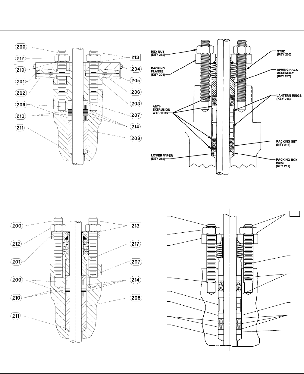
Figure 10. Live-Loaded Packing
39B4153-A
A6297-1
Typical HIGH-SEAL ULF Packing System Typical ENVIRO-SEAL Packing System
with PTFE Packing
Typical ENVIRO-SEAL Packing System
with Graphite ULF Packing
Typical ENVIRO-SEAL Packing System
with Duplex Packing
200
212
201
215
216
207
209
211
217
207
207
207
214
213
A6722
39B4612/A
Instruction Manual
D100392X012
EH Valves NPS 8 through 14
July 2014
25
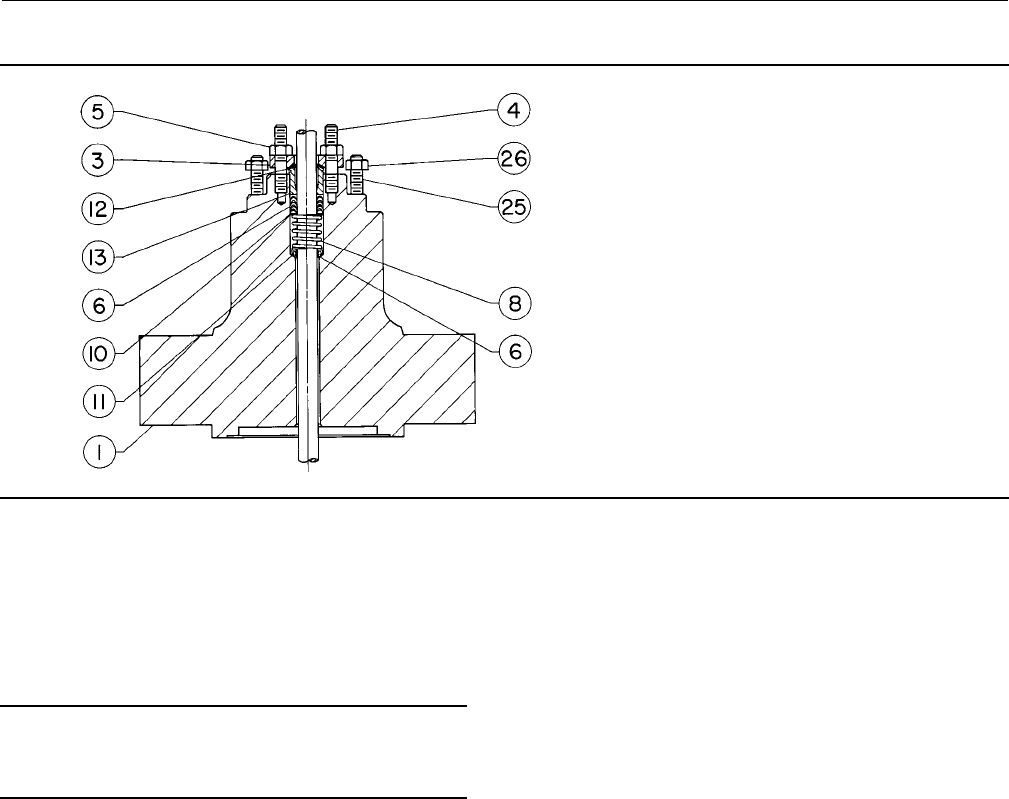
Figure 11. Bonnet Assembly
35A3976-A
Parts List
Note
Part numbers are shown for recommended spares only. For part
numbers not shown, contact your Emerson Process Management sales
office.
Bonnet Assembly (figures 4 and 11)
Key Description Part Number
1 Bonnet
If you need a bonnet as a replacement
part, order by valve size and stem
diameter, serial number, and desired
material.
3 Packing Flange
4 Packing Flange Stud
127 mm (5-inch) yoke boss diameter
(2 req'd)
178 mm (7-inch) yoke boss diameter
(3 req'd)
5 Packing Flange Nut
127 mm (5-inch) yoke boss diameter
(2 req'd)
178 mm (7-inch) yoke boss diameter
(3 req'd)
6* Packing Set See following table
7* Packing Ring See following table
Key Description Part Number
8 Spring or Lantern Ring See following table
9* Packing Ring See following table
10 Washer See following table
11* Packing Box Ring See following table
12* Upper Wiper, felt See following table
13 Packing Follower, 316 stainless
steel See following table
14 Pipe Plug (not shown)
Steel
316 stainless steel
14 Lubricator, steel (not shown)
14 Lubricator/Isolating Valve (not shown)
25 Actuator Mounting Stud, steel
(8 req'd)
26 Hex Nut, steel (8 req'd)
30* Lower Wiper, PTFE See following table
31* Male Adapter, PTFE See following table
32* Female Adapter, PTFE/glass See following table
*Recommended spare parts

Instruction Manual
D100392X012
EH Valves NPS 8 through 14
July 2014
26
Keys 6, 7, 9, 12, 30, 31 and 32 Soft Packing Parts*
VALVE STEM
CONNECTION PACKING
ARRANGEMENT
KEY
NUMBER
PACKING PART
DESCRIPTION QUANTITY PART
NUMBER
mm Inches
31.8 1-1/4
PTFE, single packing
6
31
32
7
30
Packing set (includes keys 7, 30, 31 & 32)
Male Adapter
Female Adapter
V-ring
Lower Wiper
1
1
1
3
1
1R290801012
1H995701012
1H995801012
1D387601012
1J872506992
12 Upper Wiper 11J873006332
PTFE, double packing
6
31
32
7
30
Packing set
(includes keys 7, 30, 31, & 32)
Male Adapter
Female Adapter
V-ring
Lower Wiper
2
2
2
6
2
1R290801012
1H995701012
1H995801012
1K387601012
1J872506992
12 Upper Wiper 11J873006332
Low chloride-graphite laminate
and filament, single packing
7
7
Graphite Filament Packing Rings
Graphite Laminate Packing Rings
3
2
1D7520X0162
1V5666X0022
Low chloride-graphite laminate
and filament, double packing
7
7
Graphite Filament Packing Rings
Graphite Laminate Packing Rings
5
3
1D7520X0162
1V5666X0022
Graphite-composition,
double packing
7
7
Packing Rings
Packing Rings
2
3
1D752001052
1D751901052
12 Upper Wiper 11J873006332
PTFE-composition,
double packing
7Packing Rings 81D7520X0012
12 Upper Wiper 11J873006332
50.8 2
Low chloride-graphite laminate
and filament, single packing
7
9
Graphite Laminate Packing Rings
Graphite Filament Packing Rings
3
4
10A4801X022
1N2600X0042
Low chloride-graphite laminate
and filament, double packing
7
9
Graphite Laminate Packing Rings
Graphite Filament Packing Rings
3
4
10A4801X022
1N2600X0042
Graphite-composition,
double packing
7Packing Rings 71N2600X0032
12 Upper Wiper 11V313206332
PTFE-composition,
double packing
7Packing Rings 71N260001042
12 Upper wiper 11V313206332
Keys 8, 10, 11*, and 13 Metal Packing Parts
VALVE STEM
CONNECTION PACKING
TYPE
KEY
NUMBER
PACKING PART
DESCRIPTION
QUANTITY
REQUIRED
MATERIAL
316
Stainless Steel
mm Inches
31.8 1-1/4
PTFE, single packing
8
10
11
13
Spring
Washer
Packing box ring
Packing follower
1
1
1
1
1D387437012
1H995936042
1J873535072
1H998435072
Graphite laminate
and filament, double packing
8
11
13
Lantern ring
Packing box ring
Packing follower
Warning Tag
2
1
1
1
0W087135072
1J873535072
1H998435072
11B9513X012
PTFE, PTFE-composition,
graphite-composition, graphite
laminate and filament, double
packing
8
11
13
Lantern ring
Packing box ring
Packing follower
Warning Tag
1
1
1
1
0W087135072
1J873535072
1H998435072
11B9513X012
50.8 2
Graphite laminate and filament,
single packing
PTFE-composition, graphite-
composition, graphite laminate
and filament, double
packing
8
11
13
Lantern ring
Packing box ring
Packing follower
Warning Tag
1
1
1
1
1V313335072
1V312735072
1V312835072
11B9513X012
*Recommended spare parts

Instruction Manual
D100392X012
EH Valves NPS 8 through 14
July 2014
27
Valve Assembly (figures 12, 13, and 14)
Key Description Part Number
1ValveBody
If you need a valve body as a replace-
ment part, order by valve size, serial
number, and desired material.
2* Cage See following table
3* Valve Plug See following tables
4* Valve Plug Stem See following tables
5* Pin, stainless steel
For use with 31.8 mm (1-1/4 inch)
valve plug stem 1V334035072
For use with 50.8 mm (2-inch)
valve plug stem 15A4000X012
6* Seat Ring See following tables
7 Seat Ring Cap Screw See following tables
8* Piston Ring, graphite
For all EHD valves (3 req'd)
except those with Whisper Trim III
cages
NPS 8 and 10 valves
CL1500 1U5069X0012
CL1500 high-temperature 1U5069X0022
CL2500 11A9727X022
CL2500 high-temperature 11A9727X032
NPS 12 and 14 valves
CL1500 15A3945X012
CL1500 high-temperature 15A3945X022
CL2500 1U5069X0012
CL2500 high-temperature 1U5069X0022
For EHD valve with Whisper
Trim III cage only (3 req'd for Level
A,BorCand4req'dforLevelD)
NPS 8 and 10 valves
CL1500 1U5069X0012
CL1500 high-temperature 1U5069X0022
CL2500 11A9727X022
CL2500 high-temperature 11A9727X032
NPS 12 and 14 valves
CL1500 15A3945X012
CL1500 high-temperature 15A3945X022
CL2500 1U5069X0012
CL2500 high-temperature 1U5069X0022
8* Seal Ring, N10276/PTFE (for use only
with EHT valve)
For valve with other than Whisper
Trim III cage
NPS 8 and 10 valves
CL1500 15A4010X022
CL2500 15A3974X022
NPS 12 and 14 valves
CL1500 15A3946X022
CL2500 15A4010X022
ForvalvewithWhisperTrimIIIcage
NPS 8 and 10 valves
CL1500 15A4010X032
CL2500 15A3974X022
NPS 12 and 14 valves
CL1500 15A3946X032
CL2500 15A4010X022
Key Description Part Number
9* Backup Ring (for use only with
EHT valve)
For valve with other than Whisper Trim III cage
NPS 8 and 10 valves
CL1500
316 stainless steel 15A4009X022
416 stainless steel 15A4009X012
CL2500
316 stainless steel 10A5409X022
416 stainless steel 10A5409X012
NPS 12 and 14 valves
CL1500
316 stainless steel 15A3944X022
416 stainless steel 15A3944X012
CL2500
316 stainless steel 15A4009X022
416 stainless steel 15A4009X012
ForvalvewithWhisperTrimIIIcage
NPS 8 and 10 valves
CL1500
316 stainless steel 19A9136X012
N06600 19A9136X022
17-4PH stainless steel, H1075
heat-treated 19A9136X032
17-4PH stainless steel, H1150 dbl
heat-treated
(for sour gas service) 19A9136X042
CL2500
316 stainless steel 19A9115X012
N06600 19A9115X022
17-4PH stainless steel, H1075
heat-treated 19A9115X032
17-4PH stainless steel, H1150 dbl
heat-treated
(for sour gas service) 19A9115X042
NPS 12 and 14 valves
CL1500
316 stainless steel 19A9165X012
N06600 19A9165X022
17-4PH stainless steel, H1075
heat-treated 19A9165X032
17-4PH stainless steel, H1150 dbl
heat-treated
(for sour gas service) 19A9165X042
CL2500
316 stainless steel 19A9136X012
N06600 19A9136X022
17-4PH stainless steel, H1075
heat-treated 19A9136X032
17-4PH stainless steel, H1150 dbl
heat-treated
(for sour gas service) 19A9136X042
10* Retaining Ring, 302 stainless steel (for EHT valve only)
NPS 8 and 10 valves
CL1500 14A4652X012
CL2500 10A5410X012
NPS 12 and 14 valves
CL1500 15A3933X012
CL2500 14A4652X012
*Recommended spare parts
Instruction Manual
D100392X012
EH Valves NPS 8 through 14
July 2014
28
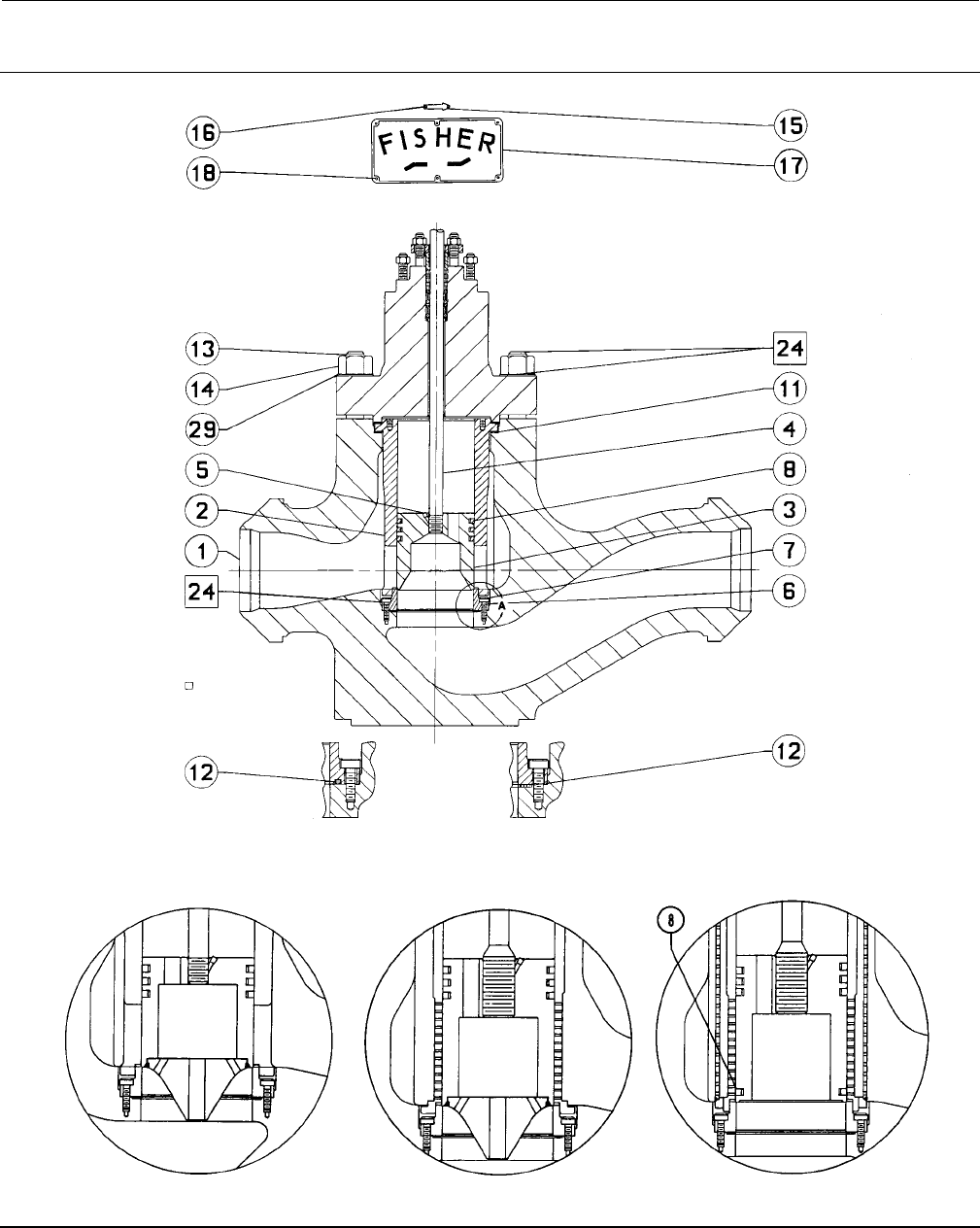
Figure 12. Fisher EHD Valve
FLOW DIRECTION FOR ALL TRIMS EXCEPT THOSE WITH WHISPER TRIM III CAGES
O-RING
CONSTRUCTION
GASKET
CONSTRUCTION
VIEW A
APPLY LUBRICANT
59A9171-A
COMPLETE VALVE SHOWING VALVE PLUG WITHOUT DIVERTER CONE
DIVERTER CONE DETAIL WHISPER TRIM
LEVELA,B,ORCDETAIL
WHISPER TRIM
LEVEL D DETAIL
59A9172-A
C0632-1 59A9180-A 59A9182-A
Instruction Manual
D100392X012
EH Valves NPS 8 through 14
July 2014
29
Figure 13. Belleville Washer Body-to-Bonnet Bolting
GE60624-C
BONNET
SHOWN IN
UNCOMPRESSED
“FREE” POSITION
Instruction Manual
D100392X012
EH Valves NPS 8 through 14
July 2014
30
Figure 14. Fisher EHT Valve
FLOW DIRECTION FOR ALL TRIMS EXCEPT THOSE WITH WHISPER TRIM III CAGES
O-RING
CONSTRUCTION
GASKET
CONSTRUCTION
VIEW A
APPLY LUBRICANT
59A9177-A
COMPLETE VALVE SHOWING VALVE PLUG WITHOUT DIVERTER CONE
DIVERTER CONE DETAIL WHISPER TRIM
LEVELA,B,ORCDETAIL WHISPER TRIM
LEVEL D DETAIL
59A9184-A 59A9186-A
59A9178-A
C0633-1
VIEW B
Instruction Manual
D100392X012
EH Valves NPS 8 through 14
July 2014
31
Key Description Part Number
11* Cage Gasket (2 req'd)
For standard service, silver pl
N04400
NPS 8 and 10 valves
CL1500 29A9220X012
CL2500 29A9221X012
NPS 12 and 14 valves
CL1500 29A9222X012
CL2500 29A9223X012
For sour gas service, tin pl N04400
NPS 8 and 10 valves
CL1500 29A9220X022
CL2500 29A9221X022
NPS 12 and 14 valves
CL1500 29A9222X022
CL2500 29A9223X022
12* Seat Ring Gasket
Spiral wound N06600
NPS 8 and 10 valves
CL1500 19A7468X012
CL2500 19A7469X012
NPS 12 and 14 valves
CL1500 19A7470X012
CL2500 19A7471X012
12* Seat Ring O-Ring
NPS 8 and 10 valves
CL1500
Nitrile 1D5470X0032
Ethylene/propylene 1D5470X0042
Fluorocarbon 1D5470X0012
CL2500
Nitrile 19A9013X012
Ethylene/propylene 19A9013X042
Fluorocarbon 19A9013X032
NPS 12 and 14 valves
CL1500
Nitrile 19A9014X012
Ethylene/propylene 19A9014X042
Fluorocarbon 19A9014X032
CL2500
Nitrile 1D5470X0032
Ethylene/propylene 1D5470X0042
Fluorocarbon 1D5470X0012
13 Bonnet Stud (12 required)
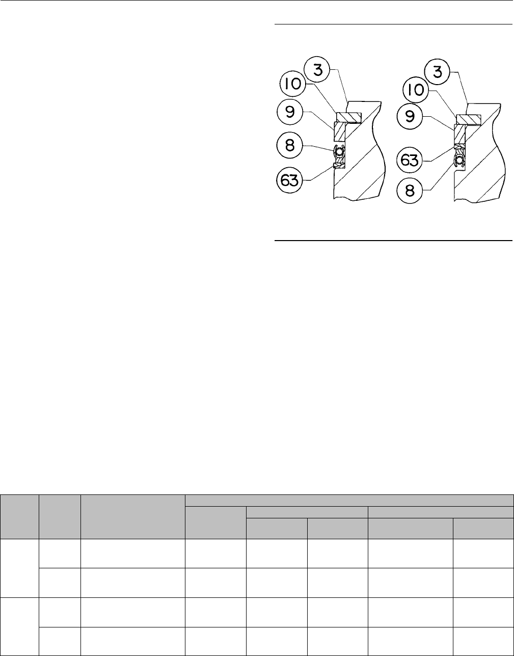
Figure 15. Fisher EHT Valve Using
PEEK Anti-Extrusion Rings
FLOW UP FLOW DOWN
A7220
Key Description Part Number
14 Hex Nut (12 req'd)
15 Flow Arrow, stainless steel
16 Drive Screw, stainless steel
(2 req'd)
17 Nameplate, stainless steel
18 Drive Screw, stainless steel
(6 req'd)
24 Anti-seize lubricant,
(not furnished with valve)
29 Flat Washer (12 req'd)
30* Piston Ring, graphite (for EHD
valve with Level D Whisper Trim III
cage only)
NPS 8 and 10 valves
CL1500 1U5069X0012
CL2500 11A9727X022
NPS 12 and 14 valves
CL1500 15A3945X012
CL2500 1U5069X0012
33 Belleville Washer, N07718 (12 req'd)
63 Anti-Extrusion Ring
Key 2* Cage for Valve without Whisper Trim III Cage
VALVE
SIZE,
NPS
VALVE
RATING
CAGE
CONSTRUCTION
MATERIAL
CA6NM
CA6NM, Cr Ct 316 Stainless Steel
To 427_C
(800_F)
Above 427_C
(800_F)
Cr Ct,
for Standard Service
ENC, for Sour
Gas Service
8, 10
CL1500
Equal percentage
Linear
Modified equal percentage
49A7423X012
39A7420X012
49A7423X012
49A7424X012
39A7421X012
49A7424X012
49A7425X012
39A7422X012
49A7425X012
49A7424X022
39A7421X022
49A7424X022
49A9000X012
39A9001X012
49A9000X012
CL2500
Equal percentage
Linear
Modified equal percentage
49A7429X012
39A7426X012
49A7429X012
49A7430X012
39A7427X012
49A7430X012
49A7431X012
39A7428X012
49A7431X012
49A7430X022
39A7427X022
49A7430X022
49A9002X012
39A9003X012
49A9002X012
12, 14
CL1500
Equal percentage
Linear
Modified equal percentage
39A7435X012
39A7432X012
39A7435X012
39A7436X012
39A7433X012
39A7436X012
39A7437X012
39A7434X012
39A7437X012
39A7436X022
39A7433X022
39A7436X022
---
---
---
CL2500
Equal percentage
Linear
Modified equal percentage
49A7441X012
39A7438X012
49A7441X012
49A7442X012
39A7439X012
49A7442X012
49A7443X012
39A7440X012
49A7443X012
49A7442X022
39A7439X022
49A7442X022
---
---
---
*Recommended spare parts

Instruction Manual
D100392X012
EH Valves NPS 8 through 14
July 2014
32
Key 2* Whisper Trim III Cage
VALVE
SIZE,
NPS
CAGE
CONSTRUCTION
Cr Ct
M152 SST
17-4PH STAINLESS STEEL WITH
H1150 DBL HEAT-TREATMENT
FOR SOUR GAS SERVICE
CL1500 Rating CL2500 Rating CL1500 Rating CL2500 Rating
8, 10
Level A1
Level A3
Level B1
Level B3
Level C1
Level C3
Level D1(1)
Level D3(1)
30B1118X012
30B1120X012
30B1122X012
30B1124X012
30B1126X012
30B1128X012
30B1185X012
30B1185X022
30B1130X012
30B1132X012
30B1134X012
30B1136X012
30B1138X012
30B1140X012
30B1189X012
30B1189X022
30B1119X012
30B1121X012
30B1123X012
30B1125X012
30B1127X012
30B1129X012
30B1186X012
30B1186X022
30B1131X012
30B1133X012
30B1135X012
30B1137X012
30B1139X012
30B1141X012
30B1190X012
30B1190X022
12, 14
Level A1
Level A3
Level B1
Level B3
Level C1
Level C3
Level D1(1)
Level D3(1)
30B1142X012
30B1144X012
30B1146X012
30B1148X012
30B1150X012
30B1152X012
30B1193X012
30B1193X022
30B1154X012
30B1156X012
30B1158X012
30B1160X012
30B1162X012
30B1164X012
30B1197X012
30B1197X022
30B1143X012
30B1145X012
30B1147X012
30B1149X012
30B1151X012
30B1153X012
30B1194X012
30B1194X022
30B1155X012
30B1157X012
30B1159X012
30B1161X012
30B1163X012
30B1165X012
30B1198X012
30B1198X022
1. This part number represents a cage and baffle assembly.
Key 3* Valve Plug for Valve without Whisper Trim III Cage
VALVE SIZE,
NPS
VALVE
RATING
VALVE/PLUG
DESIGN
VALVE STEM
CONNECTION
SIZE
HEAT TREATED 420
STAINLESS STEEL
(EHD OR EHT)
316 STAINLESS STEEL WITH
ALLOY 6 (CoCr-A) SEAT AND GUIDE
For Use Only with
Cr Ct 316 SST Cage
For Service Above
121_C (250_F)
mm Inches
8, 10
CL1500
EHD w/o
diverter cone
31.8
50.8
1-1/4
2
35A3998X012
35A3997X012
35A4001X012
35A4003X012
35A4002X012
35A4004X012
EHD with diverter cone 50.8 2--- 39A9047X012 39A9048X012
EHT w/o
diverter cone
31.8
50.8
1-1/4
2
35A3991X012
35A3992X012
35A4005X012
35A4007X012
35A4006X012
35A4008X012
EHT with diverter cone 50.8 2--- 39A9049X012 39A9050X012
CL2500
EHD w/o
diverter cone
31.8
50.8
1-1/4
2
35A3963X012
39A7494X012
35A3970X012
39A7495X012
35A3971X012
39A7496X012
EHD with diverter cone 50.8 2--- 39A9043X012 39A9044X012
EHT w/o
diverter cone
31.8
50.8
1-1/4
2
35A3962X012
39A7497X012
35A3968X012
39A7498X012
35A3969X012
39A7499X012
EHT with diverter cone 50.8 2--- 39A9045X012 39A9046X012
12, 14
CL1500
EHD w/o
diverter cone
31.8
50.8
1-1/4
2
35A3926X012
35A3927X012
35A3937X012
35A3939X012
35A3938X012
35A3940X012
EHD with diverter cone 50.8 2--- 39A9051X012 39A9052X012
EHT w/o
diverter cone
31.8
50.8
1-1/4
2
35A3924X012
35A3925X012
35A3935X012
35A3941X012
35A3936X012
35A3942X012
CL2500
EHT with diverter cone 50.8 2--- 39A9053X012 39A9054X012
EHD w/o
diverter cone
31.8
50.8
1-1/4
2
35A3998X012
35A3997X012
35A4001X012
35A4003X012
35A4002X012
35A4004X012
EHD with diverter cone 50.8 2--- 39A9047X012 39A9048X012
EHT w/o
diverter cone
31.8
50.8
1-1/4
2
35A3991X012
35A3992X012
35A4005X012
35A4007X012
35A4006X012
35A4008X012
EHT with diverter cone 50.8 2--- 39A9049X012 39A9050X012
*Recommended spare parts

Instruction Manual
D100392X012
EH Valves NPS 8 through 14
July 2014
33
Key3*ValvePlugforNPS8or10FisherEHDwithWhisperTrimIIICage
MATERIAL
OPERATING
TEMPERATURE
LIMITS
VALVE
STEM
CONNECTION
VALVE RATING
CL1500 CL2500
_C_Fmm Inches LevelA,B,orC Level D Level A, B, or C Level D
17-4PH stainless steel,
H900 heat-treated -29 to 427 -20 to 800 31.8 1-1/4 --- 39A9122X012 --- 39A9137X012
50.8 2--- 39A9124X012 --- 39A9139X012
316 stainless steel, alloy 6
(CoCr-A) seat and guide
-29 to 149 -20 to 300 31.8 1-1/4 39A9130X012 39A9126X012 39A9145X012 39A9141X012
50.8 239A9132X012 39A9128X012 39A9147X012 39A9143X012
93 to 204 200 to 400 31.8 1-1/4 39A9130X022 39A9126X022 39A9145X022 39A9141X022
50.8 239A9132X022 39A9128X022 39A9147X022 39A9143X022
149 to 260 300 to 500 31.8 1-1/4 39A9130X032 39A9126X032 39A9145X032 39A9141X032
50.8 239A9132X032 39A9128X032 39A9147X032 39A9143X032
204 to 316 400 to 600 31.8 1-1/4 39A9130X042 39A9126X042 39A9145X042 39A9141X042
50.8 239A9132X042 39A9128X042 39A9147X042 39A9143X042
260 to 371 500 to 700 31.8 1-1/4 39A9130X052 39A1926X052 39A9145X052 39A9141X052
50.8 239A9132X052 39A9128X052 39A9147X052 39A9143X052
316 to 427 600 to 800 31.8 1-1/4 39A9130X062 39A9126X062 39A9145X062 39A9141X062
50.8 239A9132X062 39A9128X062 39A9147X062 39A9143X062
371 to 482 700 to 900 31.8 1-1/4 39A9130X072 39A9126X072 39A9145X072 39A9141X072
50.8 239A9132X072 39A9128X072 39A9147X072 39A9143X072
427 to 538 800 to 1000 31.8 1-1/4 39A9130X082 39A9126X082 29A9145X082 39A9141X082
50.8 239A9132X082 39A9128X082 39A9147X082 39A9143X082
482 to 593 900 to 1100 31.8 1-1/4 39A9130X092 39A9126X092 39A9145X092 39A9141X092
50.8 239A9132X092 39A9128X092 39A9147X092 39A9143X092
N06600, alloy 6
(CoCr-A) seat and guide
-29 to 232 -20 to 450 31.8 1-1/4 39A9130X102 39A9126X102 39A9145X102 39A9141X102
50.8 239A9132X102 39A1928X102 39A9147X102 39A9143X102
233 to 427 451 to 800 31.8 1-1/4 39A9130X112 39A9126X112 39A9145X112 39A9141X112
50.8 239A9132X112 39A9128X112 39A9147X112 39A9143X112
428 to 593 801 to 1100 31.8 1-1/4 39A9130X122 39A9126X122 39A9145X122 39A9141X122
50.8 239A9132X122 39A9128X122 39A9147X122 39A9143X122
17-4 stainless steel, H1150
heat-treated, alloy 6 (CoCr-A)
seat and guide
-29 to 427 -20 to 800
31.8 1-1/4 39A9130X132 39A9126X132 39A9145X132 39A9141X132
50.8 239A9132X132 39A9128X132 39A9147X132 39A9143X132
17-4 stainless steel, H1150
DBL heat-treated, alloy 6
(CoCr-A) seat and guide, for
sour gas service
-29 to 232 -20 to 450
31.8 1-1/4 39A9130X142 39A9126X142 39A9145X142 39A9141X142
50.8 239A9132X142 39A9128X142 39A9147X142 39A9143X142
*Recommended spare parts

Instruction Manual
D100392X012
EH Valves NPS 8 through 14
July 2014
34
Key 3* Valve Plug for NPS 12 or 14 Fisher EHD with Whisper Trim III Cage
MATERIAL
OPERATING
TEMPERATURE
LIMITS
VALVE
STEM
CONNECTION
VALVE RATING
CL1500 CL2500
_C_Fmm Inches LevelA,B,orC Level D Level A, B, or C Level D
17-4PH stainless steel,
H900 heat-treated -29 to 427 -20 to 800 31.8 1-1/4 --- 39A9151X012 --- 39A9122X012
50.8 2--- 39A9153X012 --- 39A9124X012
316 stainless steel, alloy 6
(CoCr-A) seat and guide
-29 to 149 -20 to 300 31.8 1-1/4 39A9159X012 39A9155X012 39A9130X012 39A9126X012
50.8 239A9161X012 39A9157X012 39A9132X012 39A9128X012
93 to 204 200 to 400 31.8 1-1/4 39A9159X022 39A9155X022 39A9130X022 39A9126X022
50.8 239A9161X022 39A9157X022 39A9132X022 39A9128X022
149 to 260 300 to 500 31.8 1-1/4 39A9159X032 39A9155X032 39A9130X032 39A9126X032
50.8 239A9161X032 39A9157X032 39A9132X032 39A9128X032
204 to 316 400 to 600 31.8 1-1/4 39A9159X042 39A9155X042 39A9130X042 39A9126X042
50.8 239A9161X042 39A9157X042 39A9132X042 39A9128X042
260 to 371 500 to 700 31.8 1-1/4 39A9159X052 39A1955X052 39A9130X052 39A9126X052
50.8 239A9161X052 39A9157X052 39A9132X052 39A9128X052
316 to 427 600 to 800 31.8 1-1/4 39A9159X062 39A9155X062 39A9130X062 39A9126X062
50.8 239A9161X062 39A9157X062 39A9132X062 39A9128X062
371 to 482 700 to 900 31.8 1-1/4 39A9159X072 39A9155X072 39A9130X072 39A9126X072
50.8 239A9161X072 39A9157X072 39A9132X072 39A9128X072
427 to 538 800 to 1000 31.8 1-1/4 39A9159X082 39A9155X082 29A9130X082 39A9126X082
50.8 239A9161X082 39A9157X082 39A9132X082 39A9128X082
482 to 593 900 to 1100 31.8 1-1/4 39A9159X092 39A9155X092 39A9130X092 39A9126X092
50.8 239A9161X092 39A9157X092 39A9132X092 39A9128X092
N06600, alloy 6 (CoCr-A)
seat and guide
-29 to 232 -20 to 450 31.8 1-1/4 39A9159X102 39A9155X102 39A9130X102 39A9126X102
50.8 239A9161X102 39A1957X102 39A9132X102 39A9128X102
233 to 427 451 to 800 31.8 1-1/4 39A9159X112 39A9155X112 39A9130X112 39A9126X112
50.8 239A9161X112 39A9157X112 39A9132X112 39A9128X112
428 to 593 801 to 1100 31.8 1-1/4 39A9159X122 39A9155X122 39A9130X122 39A9126X122
50.8 239A9161X122 39A9157X122 39A9132X122 39A9128X122
17-4 stainless steel, H1150
heat-treated, alloy 6 (CoCr-A)
seat and guide
-29 to 427 -20 to 800
31.8 1-1/4 39A9159X132 39A9155X132 39A9130X132 39A9126X132
50.8 239A9161X132 39A9157X132 39A9132X132 39A9128X132
17-4 stainless steel, H1150
DBL heat-treated, alloy 6
(CoCr-A) seat and guide, for
sour gas service
-29 to 232 -20 to 450
31.8 1-1/4 39A9200X012 39A9196X012 39A9130X142 39A9126X142
50.8 239A9202X012 39A9198X012 39A9132X142 39A9128X142
*Recommended spare parts

Instruction Manual
D100392X012
EH Valves NPS 8 through 14
July 2014
35
Key 3* Valve Plug for Fisher EHT with Whisper Trim III Cage
VALVE
SIZE,
NPS
MATERIAL
OPERATING
TEMPERATURE
LIMITS
VALVE
STEM
CONNECTION
VALVE RATING
CL1500 CL2500
_C_Fmm Inches LevelA,B,orC Level D LevelA,B,orC Level D
8, 10
17-4 stainless steel,
H1075 heat-treated -29 to 232 -20 to 450 31.8 1-1/4 --- 39A9123X012 --- 39A9138X012
50.8 2--- 39A9125X012 --- 39A9140X012
316 stainless steel, alloy 6
(CoCr-A) seat and guide
-29 to 149 -20 to 300 31.8 1-1/4 39A9131X012 39A9127X012 39A9146X012 39A9142X012
50.8 239A9133X012 39A9129X012 39A9148X012 39A9144X012
93 to 204 200 to 400 31.8 1-1/4 39A9131X022 39A9127X022 39A9146X022 39A9142X022
50.8 239A9133X022 39A9129X022 39A9148X022 39A9144X022
149 to 232 300 to 450 31.8 1-1/4 39A9131X032 39A9127X032 39A9146X032 39A9142X032
50.8 239A9133X032 39A9129X032 39A9148X032 39A9144X032
N06600, alloy 6 (CoCr-A)
seat and guide -29 to 232 -20 to 450 31.8 1-1/4 39A9131X042 39A9127X042 39A9146X042 39A9142X042
50.8 239A9133X042 39A9129X042 39A9148X042 39A9144X042
17-4 stainless steel, H1150
heat-treated, alloy 6
(CoCr-A) seat and guide
-29 to 232 -20 to 450
31.8 1-1/4 39A9131X052 39A9127X052 39A9146X052 39A9142X052
50.8 239A9133X052 39A9129X052 39A9148X052 39A9144X052
17-4 stainless steel, H1150
DBL heat-treated, alloy 6
(CoCr-A) seat and guide,
forsourgasservice
-29 to 149 -20 to 300
31.8 1-1/4 39A9131X062 39A9127X062 39A9146X062 39A9142X062
50.8 239A9133X062 39A9129X062 39A9148X062 39A9144X062
12, 14
17-4 stainless steel,
H900 heat-treated -29 to 232 -20 to 450 31.8 1-1/4 --- 39A9152X012 --- 39A9123X012
50.8 2--- 39A9154X012 --- 39A9125X012
316 stainless steel, alloy 6
(CoCr-A) seat and guide
-29 to 149 -20 to 300 31.8 1-1/4 39A9160X012 39A9156X012 39A9131X012 39A9127X012
50.8 239A9162X012 39A9158X012 39A9133X012 39A9129X012
93 to 204 200 to 400 31.8 1-1/4 39A9160X022 39A9156X022 39A9131X022 39A9127X022
50.8 239A9162X022 39A9158X022 39A9133X022 39A9129X022
149 to 232 300 to 450 31.8 1-1/4 39A9160X032 39A9156X032 39A9131X032 39A9127X032
50.8 239A9162X032 39A9158X032 39A9133X032 39A9129X032
N06600, alloy 6 (CoCr-A)
seat and guide -29 to 232 -20 to 450 31.8 1-1/4 39A9160X042 39A9156X042 39A9131X042 39A9127X042
50.8 239A9162X042 39A9158X042 39A9133X042 39A9129X042
17-4 stainless steel, H1150
heat-treated, alloy 6
(CoCr-A) seat and guide
-29 to 232 -20 to 450
31.8 1-1/4 39A9160X052 39A9156X052 39A9131X052 39A9127X052
50.8 239A9162X052 39A9158X052 39A9133X052 39A9129X052
17-4 stainless steel, H1150
DBL heat-treated, alloy 6
(CoCr-A) seat and guide,
forsourgasservice
-29 to 149 -20 to 300
31.8 1-1/4 39A9201X012 39A9197X012 39A9131X062 39A9127X062
50.8 239A9203X012 39A9199X012 39A9133X062 39A9129X062
*Recommended spare parts

Instruction Manual
D100392X012
EH Valves NPS 8 through 14
July 2014
36
Key 4* Valve Plug Stem for NPS 8 or 10 Fisher EHD or EHT Valve without Whisper Trim III Cage
VALVE
RATING
VALVE
DESIGN
VALVE
STEM
CONNECTION ACTUATOR
GROUP
TRAVEL
MATERIAL
17-4
Stainless
Steel, H1150
Heat Treated
316 Stainless Steel S20910
mm Inches mm Inches Non-
coated Cr Ct Non-
coated Cr Ct
CL1500
EHD
31.8 1-1/4
100, 101
404
405
406
407
76
89
89
89
89
3
3.5
3.5
3.5
3.5
11A3430X632
11A3430X632
11A3430X582
11A3430X562
11A3430XH62
11A3430X622
11A3430X622
11A3430X572
11A3430X552
11A3430X592
15A4075X052
15A4075X052
15A4075X032
15A4075X022
15A4075X092
11A3430XG12
11A3430XG12
11A3430XF72
11A3430XF62
11A3430XF82
---
---
---
---
---
31.8
x
50.8
1-1/4 x 2
100, 101
404
405
406
407
76
89
89
89
89
3
3.5
3.5
3.5
3.5
29A5895X122
29A5895X122
29A5895X092
29A5895X082
29A5895X102
---
---
---
---
---
---
---
---
---
---
29A5895X272
29A5895X272
29A5895X242
29A5895X232
29A5895X252
29A6602X062
29A6602X062
29A6602X032
29A6602X022
29A6602X042
50.8 2408
409
89
89
3.5
3.5
14A1430X442
14A1430X432
14A1430X152
14A1430X182
15A4076X012
15A4076X022
14A1430X342
14A1430X332
---
---
EHT
31.8 1-1/4
100, 101
404
405
406
407
76
89
89
89
89
3
3.5
3.5
3.5
3.5
11A3430X702
11A3430X702
11A3430X652
11A3430X612
11A3430XH72
11A3430X692
11A3430X692
11A3430X642
11A3430X602
11A3430X662
---
---
---
---
---
11A3430XG62
11A3430XG62
11A3430XG22
11A3430XF92
11A3430XG32
---
---
---
---
---
31.8
x
50.8
1-1/4 x 2
100, 101
404
405
406
407
76
89
89
89
89
3
3.5
3.5
3.5
3.5
29A5895X172
29A5895X172
29A5895X132
29A5895X112
29A5895X152
---
---
---
---
---
---
---
---
---
---
29A5895X432
29A5895X432
29A5895X282
29A5895X262
29A5895X412
---
---
---
---
---
50.8 2408
409
89
89
3.5
3.5
14A1430X452
14A1430X322
14A1430X102
14A1430X192
---
---
14A1430X372
14A1430X362
---
---
CL2500
EHD
31.8 1-1/4
100
101
100, 101
64
64
76
2.5
2.5
3
11A3430X632
11A3430X612
11A3430X612
11A3430X622
11A3430X602
11A3430X602
15A4075X052
15A4075X042
15A4075X042
11A3430XG12
11A3430XF92
11A3430XF92
---
---
---
31.8
x
50.8
1-1/4 x 2
100
101
100, 101
64
64
76
2.5
2.5
3
29A5895X132
29A5895X112
29A5895X112
---
---
---
---
---
---
29A5895X282
29A5895X262
29A5895X262
29A6602X072
29A6602X052
29A6602X052
EHT
31.8 1-1/4
100
101
100, 101
64
64
76
2.5
2.5
3
11A3430X702
11A3430X682
11A3430X682
11A3430X692
11A3430X672
11A3430X672
---
---
---
11A3430XG62
11A3430XG42
11A3430XG42
---
---
---
31.8
x
50.8
1-1/4 x 2
100
101
100, 101
64
64
76
2.5
2.5
3
29A5895X182
29A5895X162
29A5895X162
---
---
---
---
---
---
29A5895X312
29A5895X302
29A5895X302
---
---
---
*Recommended spare parts

Instruction Manual
D100392X012
EH Valves NPS 8 through 14
July 2014
37
Key 4* Valve Plug Stem for NPS 12 or 14 Fisher EHD or EHT Valve without Whisper Trim III Cage
VALVE
RATING
VALVE
DESIGN
VALVE
STEM
CONNECTION ACTUATOR
GROUP
TRAVEL
MATERIAL
17-4
Stainless
Steel, H1150
Heat Treated
316 Stainless Steel S20910
mm Inches mm Inches Non-
coated Cr Ct Non-
coated Cr Ct
CL1500
EHD
and
EHT
31.8 1-1/4
404
405, 406
407
802
490
102
102
102
114
114
4
4
4
4.5
4.5
11A3430X682
11A3430XH62
11A3430X632
11A3430XJ12
11A3430XJ22
11A3430X672
11A3430X592
11A3430X622
11A3430X722
11A3430XH22
15A4075X072
15A4075X092
15A4075X052
15A4075X192
15A4075X202
---
---
---
---
---
---
---
---
---
---
31.8
x
50.8
1-1/4 x 2
404
405, 406
407
802
490
102
102
102
114
114
4
4
4
4.5
4.5
29A5895X162
29A5895X102
29A5895X122
29A5895X212
29A5895X222
---
---
---
---
---
---
---
---
---
---
29A5895X302
29A5895X252
29A5895X272
29A5895X332
29A5895X342
29A6602X092
29A6602X042
29A6602X062
29A6602X102
29A6602X112
50.8 2
408, 409
802
490
102
114
114
4
4.5
4.5
14A1430X462
14A1430X482
14A1430X512
14A1430X222
14A1430X122
14A1430X232
15A4076X072
15A4076X052
15A4076X082
---
---
---
---
---
---
CL2500
EHD
31.8 1-1/4
100, 101
404
405
406
407
76
89
89
89
89
3
3.5
3.5
3.5
3.5
11A3430XH92
11A3430XH92
11A3430XH72
11A3430X632
11A3430XH82
11A3430X712
11A3430X712
11A3430X662
11A3430X622
11A3430X362
15A4075X102
15A4075X102
15A4075X132
15A4075X052
15A4075X122
---
---
---
---
---
---
---
---
---
---
31.8
x
50.8
1-1/4 x 2
100, 101
404
405
406
407
76
89
89
89
89
3
3.5
3.5
3.5
3.5
29A5895X182
29A5895X182
29A5895X142
29A5895X122
29A5895X162
---
---
---
---
---
---
---
---
---
---
29A5895X312
29A5895X312
29A5895X292
29A5895X272
29A5895X302
29A6602X012
29A6602X012
29A6602X082
29A6602X062
29A6602X092
50.8 2
408
408
409
76
89
76,89
3
3.5
3, 3.5
14A1430X482
14A1430X472
14A1430X452
14A1430X122
14A1430X112
14A1430X102
15A4076X052
15A4076X062
15A4076X032
---
---
---
---
---
---
EHT
31.8 1-1/4
100, 101
404
405
406
407
76
89
89
89
89
3
3.5
3.5
3.5
3.5
11A3430XJ12
11A3430XJ12
11A3430XH92
11A3430X702
11A3430X242
11A3430X722
11A3430X722
11A3430X712
11A3430X692
11A3430X232
---
---
---
---
---
---
---
---
---
---
---
---
---
---
---
31.8
x
50.8
1-1/4 x 2
100, 101
404
405
406
407
76
89
89
89
89
3
3.5
3.5
3.5
3.5
29A5895X212
29A5895X212
29A5895X192
29A5895X172
29A5895X202
---
---
---
---
---
---
---
---
---
---
29A5895X332
29A5895X332
29A5895X422
29A5895X432
29A5895X322
---
---
---
---
---
50.8 2
408
408
409
76
89
76,89
3
3.5
3, 3.5
14A1430X502
14A1430X492
14A1430X482
14A1430X142
14A1430X132
14A1430X122
---
---
---
---
---
---
---
---
---
*Recommended spare parts
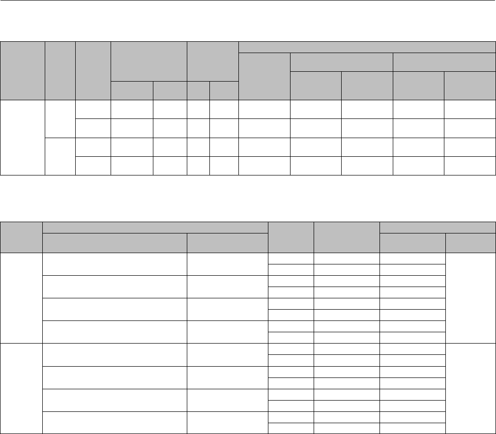
Instruction Manual
D100392X012
EH Valves NPS 8 through 14
July 2014
38
Key 4* Valve Plug Stem for Valve with Whisper Trim III Cage
ACTUATOR
GROUP
VALVE
SIZE,
NPS
VALVE
RATING
STEM
DIAMETER TRAVEL
MATERIAL
17-4PH
Stainless
Steel, H1150
Heat
Treated
316 Stainless Steel S20910
Non-
coated Cr Ct Non-
coated Cr Ct
mm Inches mm Inches
802
8, 10
CL1500 31.8
31.8 x 50.8
1-1/4
1-1/4 x 2
178
178
7
7
13A4764X262
29A9092X012
13A4764X272
---
19A9044X012
---
13A4764X282
29A9092X022
---
29A9093X012
CL2500 31.8
31.8 x 50.8
1-1/4
1-1/4 x 2
146
146
5.75
5.75
13A4764X292
29A9092X032
13A4764X302
---
19A9094X022
---
13A4764X312
29A9092X042
---
29A9093X022
12, 14
CL1500 31.8
31.8 x 50.8
1-1/4
1-1/4 x 2
184
184
7.25
7.25
13A4764X322
29A9092X052
13A4764X332
---
13A9094X032
---
13A4764X342
29A9092X062
---
29A9093X032
CL2500 31.8
31.8 x 50.8
1-1/4
1-1/4 x 2
178
178
7
7
13A4764X322
29A9092X052
13A4764X332
---
13A9094X032
---
13A4764X342
29A9092X062
---
29A9093X032
Key 6* Seat Ring and Key 7 Cap Screw for Valve with Gasket Construction and without Whisper Trim III Cage
VALVE
SIZE,
NPS
MATERIAL VALVE
RATING
KEY 6
SEAT RING
KEY 7 CAP SCREW
Seat Ring Cap Screw Part Number Quantity
Required
8, 10
17-4PH stainless steel,
H1075 heat-treated
SA-564,
H1100 heat-treated
CL1500 39A7400X032 19A7492X022
22
CL2500 39A7402X032 19A7493X022
N07718 SB-637, GR 718 CL1500 39A7400X022 19A7492X012
CL2500 39A7402X022 19A7493X012
316 stainless steel, alloy 6 (CoCr-A)
seat
SA-453-660,
CLA
CL1500 39A7401X032 19A7492X032
CL2500 39A7403X032 19A7493X032
N06600, alloy 6 (CoCr-A) seat SB-637, GR 718 CL1500 39A7401X042 19A7492X012
CL2500 39A7403X042 19A7493X012
12, 14
17-4PH stainless steel,
H1075 heat-treated
SA-564,
H1100 heat-treated
CL1500 39A7404X032 19A7493X022
28
CL2500 39A7406X032 19A7493X022
N07718 SB-637, GR 718 CL1500 39A7404X022 19A7493X012
CL2500 39A7406X022 19A7493X012
316 stainless steel, alloy 6 (CoCr-A)
seat
SA-453-660,
CLA
CL1500 39A7405X032 19A7493X032
CL2500 39A7407X032 19A7493X032
N06600, alloy 6 (CoCr-A) seat SB-637, GR 718 CL1500 39A7405X042 19A7493X012
CL2500 39A7407X042 19A7493X012
*Recommended spare parts

Instruction Manual
D100392X012
EH Valves NPS 8 through 14
July 2014
39
Key 6* Seat Ring and Key 7 Cap Screw for Valve with Gasket Construction and Whisper Trim III Cage
VALVE
SIZE,
NPS
MATERIAL VALVE
RATING
KEY 6
SEAT RING
KEY 7 CAP SCREW
Part Number Quantity
Required
Seat Ring Cap Screw
8, 10
17-4PH stainless steel,
H1075 heat-treated
SA-564,
H1100 heat-treated
CL1500 39A7400X032 19A7492X022
22
CL2500 39A7402X032 19A7493X022
17-4PH stainless steel,
H1150 heat treated,
alloy 6 (CoCr-A) seat
SA-564,
H1100 heat-treated
CL1500 39A7401X122 19A7492X022
CL2500 39A7403X122 19A7493X022
316 stainless steel, alloy 6
(CoCr-A) seat, for
temperatures up to 260_C (500_F)
SA-453-660,
CLA
CL1500 39A7401X032 19A7492X032
CL2500 39A7403X032 19A7493X032
316 stainless steel, alloy 6
(CoCr-A) seat, for
temperatures up to 427_C (800_F)
SA-453-660,
CLA
CL1500 39A7401X062 19A7492X032
CL2500 39A7403X062 19A7493X032
316 stainless steel, alloy 6
(CoCr-A) seat, for
temperatures up to 593_C (1100_F)
SA-453-660,
CLA
CL1500 39A7401X082 19A7492X032
CL2500 39A7403X082 19A7493X032
N06600, alloy 6
(CoCr-A) seat, for
temperatures up to 427_C (800_F)
SB-637, GR 718
CL1500 39A7401X042 19A7492X012
CL2500 39A7403X042 19A7493X012
N06600, alloy 6
(CoCr-A) seat, for
temperatures up to 593_C (1100_F)
SB-637, GR 718
CL1500 39A7401X102 19A7492X012
CL2500 39A7403X102 19A7493X012
N07718, heat-treated SB-637, GR 718 CL1500 39A7400X022 19A7492X012
CL2500 39A7402X022 19A7493X012
12, 14
17-4PH stainless steel,
H1075 heat-treated
SA-564,
H1100 heat-treated
CL1500 39A9009X022 19A7493X022
28
CL2500 39A7406X032 19A7493X022
17-4PH stainless steel,
H1150 heat treated,
alloy 6 (CoCr-A) seat
SA-564,
H1100 heat-treated
CL1500 39A9010X122 19A7493X022
CL2500 39A7407X122 19A7493X022
316 stainless steel, alloy 6
(CoCr-A) seat, for
temperatures up to 260_C (500_F)
SA-453-660,
CLA
CL1500 39A9010X022 19A7493X032
CL2500 39A7407X032 19A7493X032
316 stainless steel, alloy 6
(CoCr-A) seat, for
temperatures up to 427_C (800_F)
SA-453-660,
CLA
CL1500 39A9010X042 19A7493X032
CL2500 39A7407X062 19A7493X032
316 stainless steel, alloy 6
(CoCr-A) seat, for
temperatures up to 593_C (1100_F)
SA-453-660,
CLA
CL1500 39A9010X062 19A7493X032
CL2500 39A7407X082 19A7493X032
N06600, alloy 6
(CoCr-A) seat, for
temperatures up to 427_C (800_F)
SB-637, GR 718
CL1500 39A9010X082 19A7493X012
CL2500 39A7407X042 19A7493X012
N06600, alloy 6
(CoCr-A) seat, for
temperatures up to 593_C (1100_F)
SB-637, GR 718
CL1500 39A9010X102 19A7493X012
CL2500 39A7407X102 19A7493X012
N07718, heat-treated SB-637, GR 718 CL1500 39A9009X032 19A7493X012
CL2500 39A7406X022 19A7493X012
*Recommended spare parts

Instruction Manual
D100392X012
EH Valves NPS 8 through 14
July 2014
40
Key 6* Seat Ring and Key 7 Cap Screw for Valve with O-Ring Construction and without Whisper Trim III Cage
VALVE
SIZE,
NPS
MATERIAL VALVE
RATING
KEY 6
SEAT RING
KEY 7 CAP SCREW
Seat Ring Cap Screw Part Number Quantity
Required
8, 10
17-4PH stainless steel,
H1075 heat-treated
SA-564,
H1100 heat-treated
CL1500 39A9035X022 19A7492X022
10
CL2500 39A9037X022 19A7493X022
316 stainless steel, alloy 6 (CoCr-A)
seat
SA-453-660,
CLA
CL1500 39A9036X022 19A7492X032
CL2500 39A9038X022 19A7493X032
N06600,
alloy 6 (CoCr-A) seat SB-637, GR 718 CL1500 39A9036X042 19A7492X012
CL2500 39A9038X042 19A7493X012
17-4PH stainless steel, H1150 DBL heat-
treated for sour gas service
SA-564,
H1150 heat-treated
CL1500 39A9035X042 19A7492X042
CL2500 39A9037X042 19A7493X042
N06600, alloy 6 (CoCr-A) seat,
forsourgasservice SB-637, GR 718 CL1500 39A9036X042 19A7492X052
CL2500 39A9038X042 19A7493X052
12, 14
17-4PH stainless steel,
H1075 heat-treated
SA-564,
H1100 heat-treated
CL1500 39A9039X022 19A7493X022
12
CL2500 39A9041X022 19A7493X022
316 stainless steel, alloy 6 (CoCr-A)
seat
SA-453-660,
CLA
CL1500 39A9040X022 19A7493X032
CL2500 39A9042X022 19A7493X032
N06600,
alloy 6 (CoCr-A) seat SB-637, GR 718 CL1500 39A9040X042 19A7493X012
CL2500 39A9042X042 19A7493X012
*Recommended spare parts

Instruction Manual
D100392X012
EH Valves NPS 8 through 14
July 2014
41
Key 6* Seat Ring and Key 7 Cap Screw for Valve with O-Ring Construction and Whisper Trim III Cage
VALVE
SIZE,
NPS
MATERIAL VALVE
RATING
KEY 6
SEAT RING
KEY 7 CAP SCREW
Part Number Quantity
Required
Seat Ring Cap Screw
8, 10
17-4PH stainless steel,
H1075 heat-treated
SA-564,
H1150 heat-treated
CL1500 39A9035X022 19A7492X022
10
CL2500 39A9037X022 19A7493X022
17-4PH stainless steel, H1150 heat-treated
alloy 6 (CoCr-A) seat
SA-564,
H1100 heat-treated
CL1500 39A9036X062 19A7492X022
CL2500 39A9038X062 19A7493X022
N06600,
alloy 6 (CoCr-A) seat SB-637, GR 718 CL1500 39A9036X042 19A7492X012
CL2500 39A9038X042 19A7493X012
316 stainless steel,
alloy 6 (CoCr-A) seat
SA-453-660,
CLA
CL1500 39A9036X022 19A7492X032
CL2500 39A9038X022 19A7493X032
17-4PH stainless steel, H1150 DBL
heat-treated, for sour gas service
SA-564,
H1150 heat-treated
CL1500 39A9035X042 19A7492X042
CL2500 39A9037X042 19A7493X042
17-4PH stainless steel, H1150 DBL
heat-treated, alloy 6 (CoCr-A) seat,
forsourgasservice
SA-564,
H1150 heat-treated
CL1500 39A9036X072 19A7492X042
CL2500 39A9038X072 19A7493X042
N06600, alloy 6 (CoCr-A) seat,
forsourgasservice SB-637, GR 718 CL1500 39A9036X042 19A7492X052
CL2500 39A9038X042 19A7493X052
12, 14
17-4PH stainless steel,
H1075 heat-treated
SA-564,
H1150 heat-treated
CL1500 39A9011X022 19A7493X022
12
CL2500 39A9041X022 19A7493X022
17-4PH stainless steel, H1150 heat-treated
alloy 6 (CoCr-A) seat
SA-564,
H1100 heat-treated
CL1500 39A9012X062 19A7493X022
CL2500 39A9042X062 19A7493X022
N06600,
alloy 6 (CoCr-A) seat SB-637, GR 718 CL1500 39A9012X042 19A7493X012
CL2500 39A9042X042 19A7493X012
316 stainless steel,
alloy 6 (CoCr-A) seat
SA-453-660,
CLA
CL1500 39A9012X022 19A7493X032
CL2500 39A9042X022 19A7493X032
17-4PH stainless steel, H1150 DBL
heat-treated, for sour gas service
SA-564,
H1150 heat-treated
CL1500 39A9011X042 19A7493X042
CL2500 39A9041X042 19A7493X042
17-4PH stainless steel, H1150 DBL
heat-treated, alloy 6 (CoCr-A)
seat, for sour gas service
SA-564,
H1150 heat-treated
CL1500 39A9012X072 19A7493X042
CL2500 39A9042X072 19A7493X042
N06600, alloy 6 (CoCr-A) seat,
forsourgasservice SB-637, GR 718 CL1500 39A9012X042 19A7493X052
CL2500 39A9042X042 19A7493X052
*Recommended spare parts

Instruction Manual
D100392X012
EH Valves NPS 8 through 14
July 2014
42
Actuator Groups by Type Number
Group 100
127 mm (5-Inch) Yoke Boss
Group 406
127 mm (5-Inch) Yoke Boss
472
473
474
476
585C
657
1008
667 MO
667-4 MO
Group 407
127 mm (5-Inch) Yoke Boss
474
585C
657
Group 408
127 mm (5H) and 178 mm (7-Inch) Yoke Boss
657 Size 100
1008
Group 101
127 mm (5-Inch) Yoke Boss
Group 409
127 mm (5H) and 178 mm (7-Inch) Yoke Boss
667
667 Size 100
Group 404
127 mm (5-Inch) Yoke Boss Group 802
127 mm (5-Inch) Yoke Boss
667
667-4
Group 405
127 mm (5-Inch) Yoke Boss
585C
657 MO
657-4 MO

Instruction Manual
D100392X012
EH Valves NPS 8 through 14
July 2014
43

Instruction Manual
D100392X012
EH Valves NPS 8 through 14
July 2014
44
Emerson Process Management
Marshalltown, Iowa 50158 USA
Sorocaba, 18087 Brazil
Chatham, Kent ME4 4QZ UK
Dubai, United Arab Emirates
Singapore 128461 Singapore
www.Fisher.com
The contents of this publication are presented for informational purposes only, and while every effort has been made to ensure their accuracy, they arenot
to be construed as warranties or guarantees, express or implied, regarding the products or services described herein or their use or applicability. All sales are
governed by our terms and conditions, which are available upon request. We reserve the right to modify or improve the designs or specifications of such
products at any time without notice.
E1979, 2014 Fisher Controls International LLC. All rights reserved.
Fisher, Whisper Trim, Cavitrol, and ENVIRO-SEAL are marks owned by one of the companies in the Emerson Process Management business unit of Emerson
Electric Co. Emerson Process Management, Emerson, and the Emerson logo are trademarks and service marks of Emerson Electric Co. All other marks are
the property of their respective owners.
Neither Emerson, Emerson Process Management, nor any of their affiliated entities assumes responsibility for the selection, use or maintenance
of any product. Responsibility for proper selection, use, and maintenance of any product remains solely with the purchaser and end user.
