Emerson Fisher Hp And Eh Instruction Manual D100394X012_Dec14
2015-03-30
: Emerson Emerson-Fisher-Hp-And-Eh-Instruction-Manual-680689 emerson-fisher-hp-and-eh-instruction-manual-680689 emerson pdf
Open the PDF directly: View PDF ![]() .
.
Page Count: 52

www.Fisher.com
FisherrEHD, EHS, and EHT Valves
NPS 1-1/2x1 through NPS 8x6
Contents
Introduction 1.................................
Scope of Manual 1.............................
Description 2.................................
Specifications 3...............................
Educational Services 3.........................
Installation 4..................................
Maintenance 6.................................
Packing Lubrication 7..........................
Packing Maintenance 7.........................
Replacing Packing 8........................
Trim Removal 12..............................
Valve Plug Maintenance 15.....................
Lapping Seats 16..............................
Trim Replacement 16..........................
Retrofit: Installing C-seal Trim 22................
Replacement of Installed C-seal Trim 25...........
Trim Removal (C-seal Constructions) 25.......
Lapping Metal Seats (C-seal Constructions) 27..
Remachining Metal Seats
(C-seal Constructions) 27.................
Trim Replacement (C-seal Constructions) 27...
Parts Ordering 29...............................
Parts Kits 29...................................
Parts List 30...................................
Figure 1. Fisher EH Valve with 657 Actuator
W3387
Introduction
Scope of Manual
This instruction manual includes installation, maintenance, and parts information for the Fisher EHD, EHS, and EHT
control valves in NPS 1-1/2 x 1 through NPS 8x6. Refer to separate manuals for instructions covering the actuator,
positioner, ENVIRO-SEALtpacking, HIGH-SEAL packing, and accessories.
Do not install, operate, or maintain EHD, EHS, or EHT valves without being fully trained and qualified in valve, actuator,
and accessory installation, operation, and maintenance. To avoid personal injury or property damage, it is important
to carefully read, understand, and follow all the contents of this manual, including all safety cautions and warnings. If
you have any questions about these instructions, contact your Emerson Process Management sales office before
proceeding.
Unless otherwise noted, all NACE references are to NACE MR0175-2002.
Instruction Manual
D100394X012
EH (1-1/2x1 through 8x6)
December 2014

Instruction Manual
D100394X012
EH (1-1/2x1 through 8x6)
December 2014
2
Table 1. Specifications
End Connection Styles
Buttwelding: All available ASME B16.25 schedules
that are compatible with ASME B16.34
pressure/temperature ratings
Flanged: CL2500 Jring-type joint (RTJ) or
Jraised-face (RF) flanges according to ASME B16.5
Socket Welding: Consistent with ASME B16.11
Maximum Inlet Pressure(1)
Buttwelding: Consistent with CL2500
pressure-temperature ratings per ASME B16.34
Flanged: Consistent with CL2500
pressure-temperature ratings per ASME B16.34
Socket Welding: Consistent with CL2500
pressure-temperature ratings per ASME B16.34
Shutoff Classifications
See table 2
C-seal trim: High-temperature, Class V.
See table 3
TSO (Tight Shutoff) trim: See tables 4 and 5
Flow Characteristic
Standard Cage: JEqual percentage, Jmodified
equal percentage(2),Jor linear
CavitroltIII or Whisper TrimtIII Cage: Linear
Flow Direction
EHD or EHT: Flow down, except with either a Whisper
Trim III cage or a valve plug with diverter cone, both
of which are flow up
EHS: Flow up, except flow down with Cavitrol III cage
Approximate Weights (Valve Body and Bonnet
Assemblies)
See table 6
Additional Specifications
For specifications such as materials, valve plug
travels, and port, yoke boss, and stem diameters, see
the Parts List section
1. The pressure or temperature limits in this manual and any applicable standard limitations should not be exceeded.
2. Modified equal percentage characteristic is equal-percentage for the first 90% of travel, then quick-opening for additional capacity.
Table 2. Shutoff Classifications per ANSI/FCI 70-2 and IEC 60534-4
Valve Valve Size,
NPS ANSI/FCI Leakage Class
EHD
3x2 II
3, 4x3,
4, 6x4
II–Standard
III–Optional(1)
6, 8x6 III–Standard
IV–Optional(1)
EHS w/Cavitrol III, or
EHT w/Cavitrol III All V(1)
EHS, EHT,
EHS w/Micro-Form or
EHS w/Micro Flute
All
IV–Standard
V–Optional(1)
EHT w/ PEEK Anti-Extrusion
Rings 3to6 V to 600_F (316_C)
1. O-ring seat ring construction recommended for this shutoff classification; for temperatures below 232_C (450_F) only.
Description
TheEHD,EHS,andEHThigh-pressureglobevalves(figure1)havemetalseats,cageguiding,andpush-down-to-close
valve plug action. The EHD and EHT valves use balanced valve plugs.
The EHS valve uses an unbalanced valve plug. To provide a seal between the cage and a balanced valve plug, the EHD
valve plug uses piston rings; the EHT valve plug uses a pressure-assisted seal ring. A Whisper Trim cage can be used
with an EHD, EHS, or EHT valve plug. A Cavitrol III cage can be used with an EHS or EHT valve plug.
C-seal trim is available for EHD valves, CL2500, in sizes 4, 6, 6x4, and 8x6.
With C-seal trim, a balanced valve can achieve high-temperature, Class V shutoff. Because the C-seal plug seal is
formed from metal (N07718 nickel alloy) rather than an elastomer, a valve equipped with the C-seal trim can be

Instruction Manual
D100394X012
EH (1-1/2x1 through 8x6)
December 2014
3
appliedinprocesseswithafluidtemperatureofupto593_C (1100_F), provided other material limits are not
exceeded. Contact your Emerson Process Management sales office for information.
Specifications
Specifications for the EHD, EHS, and EHT valves are shown in table 1.
Educational Services
For information on available courses for the Fisher EH valve, as well as a variety of other products, contact:
Emerson Process Management
Educational Services - Registration
Phone: 1-641-754-3771 or 1-800-338-8158
E-mail: education@emerson.com
http://www.emersonprocess.com/education
Table 3. Additional Shutoff Classification per ANSI/FCI 70-2 and IEC 60534-4
Valve (Class) Valve Size, NPS Port Diameter, Inches Cage Style ANSI/FCI Leakage
Class
EHD
(CL2500)
4
6x4 2.875
Equal Percentage, Modified Equal Percentage,
Linear (std. cage),
Linear (Whisper III, A1, B3, C3)
V(forport
diameters from 2.875
through 7-inch with
optional C-seal trim)
Linear (Cavitrol III, 2-stage)
6
8x6 4.375
Equal Percentage, Modified Equal Percentage,
Linear (std. cage),
Linear (Whisper III, A1, B3, C3, D3)
6
8x6 4.375 Linear (Cavitrol III, 2- and 3-stage)
Table 4. TSO (Tight Shutoff) Leakage Class per ANSI/FCI 70-2 and IEC 60534-4
Leakage Class Maximum Leakage Test Medium Test Pressure ANSI/FCI Leakage Class
TSO (Tight Shutoff)
Valves with TSO trim are factory tested to
a more stringent Emerson Process
Management test requirement of no
leakage at time of shipment.
Water Service P(1) V
1. Specify service Pwhenordering.
Table 5. TSO Shutoff Availability
VALVE CONSTRUCTION LEAKAGE CLASS
Standard Optional
EHS, EHT Cavitrol III trim. Replaceable, protected soft seat TSO ---
Table 6. Approximate Weights (Valve Body and Bonnet Assemblies)
VALVE
SIZE,
NPS
CL2500
Kilograms Pounds
Flg
SWE
&
BWE
Flg
SWE
&
BWE
1-1/2 x 1 --- 46 --- 101
2x1 78 47 173 104
3x2 161 94 355 207
3223 163 492 359
4x3 265 162 585 357
4338 243 745 536
6x4 526 257 1160 567
6785 544 1731 1199
8x6 955 558 2106 1231

Instruction Manual
D100394X012
EH (1-1/2x1 through 8x6)
December 2014
4
Installation
WARNING
Always wear protective gloves, clothing, and eyewear when performing any installation operations to avoid personal
injury.
To avoid personal injury or property damage resulting from the sudden release of pressure, do not install the valve
assembly where service conditions could exceed the limits given in this manual or on the appropriate nameplates. Use
pressure-relieving devices as required by government or accepted industry codes and good engineering practices.
Check with your process or safety engineer for any additional measures that must be taken to protect against process
media.
If installing into an existing application, also refer to the WARNING at the beginning of the Maintenance section in this
instruction manual.
CAUTION
Responsibility for the safety of process media and compatibility of valve materials with process media rests solely with the
purchaser and end-user. The valve configuration and construction materials meet particular pressure, temperature,
pressure drop, and controlled fluid conditions specified in the customer's order. Because some body/trim material
combinations are limited in their pressure drop and temperature range capabilities (especially due to differences in
thermal expansion rates), do not apply any other conditions to the valve without first contacting your Emerson Process
Management sales office.
CAUTION
If hoisting the valve, use a nylon sling to protect the painted surfaces. Carefully position the sling to prevent damage to the
tubing or any accessories. Use adequately sized hoists and chains or slings to handle the valve and take precautions to
prevent personnel from being injured in case the hoist or rigging slips unexpectedly. Refer to table 6 for valve assembly
weights.
WARNING
Personal injury could result from packing leakage. Valve packing was tightened prior to shipment; however some
readjustment will be required to meet specific service conditions. Check with your process or safety engineer for any
additional measures that must be taken to protect against process media.
1. Before installing the valve, inspect it to ensure that the valve body cavity is free of foreign material.
2. Clean out all pipelines to remove scale, welding slag, and other foreign materials before installing the valve.
Note
If the valve being installed has small internal flow passages, such as with Whisper Trim III or Cavitrol III cages, consideration should
be given to installing an upstream strainer to prevent the lodging of particles in these passages. This is especially important if the
pipeline cannot be thoroughly cleaned or if the flowing medium is not clean.
Instruction Manual
D100394X012
EH (1-1/2x1 through 8x6)
December 2014
5
3. The control valve must be installed with the actuator vertical above the valve body for proper operation. Flow
through the valve must be in the direction indicated by the flow arrow (key 15, figure 17, 18, or 20) on the valve
body.
4. Use accepted piping and welding practices when installing the valve in the line. For welding end valve bodies,
completely disassemble the valve removing all trim parts before welding the valve body in the line. For flanged
valve bodies, use suitable gaskets between the valve body flanges and pipeline flanges.
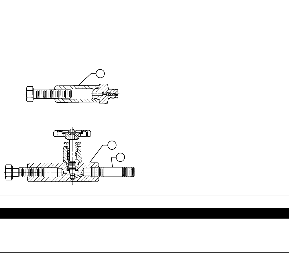
Figure 2. Lubricator and Lubricator/Isolating Valve
LUBRICATOR
LUBRICATOR/ISOLATING VALVE
10A9421-A
AJ5428-D
A0832-2
14
14
27
CAUTION
Depending on valve body materials used, post-weld heat treating might be needed. Post-weld heat treatment can damage
internal elastomeric, plastic, and metal parts. Shrunk-fit pieces and threaded connections might loosen.
If post-weld heat treating is needed, remove all trim parts to avoid any damage to internal elastomeric, plastic, and metal
parts. Contact your Emerson Process Management sales office for additional information.
5. Install a three-valve bypass around the valve if continuous operation is required during maintenance.
6. If the actuator and valve body are shipped separately, refer to the actuator mounting procedure in the appropriate
actuator instruction manual.
7. If the valve was shipped without packing installed in the packing box, install the packing before putting the valve
into service. Refer to instructions given in the Packing Maintenance procedure.
Valves with ENVIRO-SEAL live-loaded packing or HIGH-SEAL Heavy-Duty live-loaded packing will not require this initial
re-adjustment. See the Fisher instruction manuals titled ENVIRO-SEAL Packing System for Sliding-Stem Valves or
HIGH-SEAL Live-Loaded Packing System (as appropriate) for packing instructions. If you wish to convert your present
packing arrangement to ENVIRO-SEAL packing, refer to the retrofit kits listed in the parts kit sub-section near the end
of this manual.

Instruction Manual
D100394X012
EH (1-1/2x1 through 8x6)
December 2014
6
Maintenance
Valve parts are subject to normal wear and must be inspected and replaced as necessary. Inspection and maintenance
frequency depends on the severity of service conditions. This section includes instructions for packing lubrication,
packing maintenance, adding packing rings, replacing packing, trim removal, valve plug maintenance, lapping seats,
and trim replacement. All maintenance operations can be performed with the valve in the line.
WARNING
Avoid personal injury from sudden release of process pressure. Before performing any maintenance operations:
DDo not remove the actuator from the valve while the valve is still pressurized.
DAlways wear protective gloves, clothing, and eyewear when performing any maintenance operations to avoid personal
injury.
DDisconnect any operating lines providing air pressure, electric power, or a control signal to the actuator. Be sure the
actuator cannot suddenly open or close the valve.
DUse bypass valves or completely shut off the process to isolate the valve from process pressure. Relieve process pressure
on both sides of the valve. Drain the process media from both sides of the valve.
DVent the power actuator loading pressure and relieve any actuator spring precompression.
DUse lock-out procedures to be sure that the above measures stay in effect while you work on the equipment.
DThe valve packing box may contain process fluids that are pressurized, even when the valve has been removed from the
pipeline. Process fluids may spray out under pressure when removing the packing hardware or packing rings, or when
loosening the packing box pipe plug.
DCheck with your process or safety engineer for any additional measures that must be taken to protect against process
media.
Table 7. Recommended Torque for Packing Flange Nuts
STEM
DIAMETER
VALVE
BODY
RATING(1)
TORQUE
NSmLbfSFt
mm Inches Min Max Min Max
12.7 1/2 CL1500 15 22 11 16
CL2500 18 24 13 18
19.1 3/4 CL1500 34 50 25 37
CL2500 41 61 30 45
25.4 1CL1500 52 77 38 57
CL2500 61 91 45 67
31.8 1-1/4 CL1500 68 102 50 75
CL2500 81 122 60 90
1. Includes intermediate class ratings.
Note
Whenever a gasket seal is disturbed by removing or shifting gasketed parts, a new gasket should be installed upon reassembly.
This is necessary to ensure a good gasket seal.
Note
If the valve has ENVIRO-SEAL live-loaded packing installed (figure 3), see the Fisher instruction manual entitled ENVIRO-SEAL
Packing System for Sliding Stem Valves for packing instructions.
If the valve has HIGH-SEAL heavy-duty live-loaded packing installed, see Fisher instruction manual entitled HIGH-SEAL Live-Loaded
Packing Systems for packing instructions.

Instruction Manual
D100394X012
EH (1-1/2x1 through 8x6)
December 2014
7
WARNING
Personal injury could result from packing leakage. Valve packing was tightened prior to shipment; however some
readjustment will be required to meet specific service conditions. Check with your process or safety engineer for any
additional measures that must be taken to protect against process media.
Packing Lubrication
CAUTION
Do not lubricate graphite packing. Graphite packing is self-lubricated. Additional lubrication may result in slip-stick
movement of the valve.
WARNING
To avoid personal injury or property damage resulting from fire or explosion, do not lubricate packing used in oxygen
service or in processes with temperatures over 260_C (500_F).
A lubricator or lubricator/isolating valve (figure 2) is recommended for PTFE-composition packing. The lubricator or
lubricator/isolating valve is installed in place of the pipe plug (key 14, figure 16). It is recommended that a good quality
silicon-base lubricant be used. To operate the lubricator, simply turn the cap screw clockwise to force lubricant into
thepackingbox.Thelubricator/isolatingvalveoperatesthesamewayexcepttheisolatingvalvemustfirstbeopened
andthenclosedafterlubrication is completed.
Packing Maintenance
If there is undesirable packing leakage in spring-loaded PTFE V-ring packing (figure 4), tighten the packing flange nuts
(key 5, figure 16) until the shoulder on the packing follower (key 13, figure 16) contacts the bonnet (key 1, figure 16).
If leakage continues, replace the packing by following the numbered steps presented in the Replacing Packing
procedure.
CAUTION
When tightening packing flange nuts, do not exceed the maximum recommended torque in table 7 or excessive friction
may result, resulting in keeping the valve from stroking fully and not attaining proper seat load.
If there is undesirable packing leakage with other than spring-loaded PTFE V-ring packing, first try to limit the leakage
and establish a stem seal by tightening the packing flange nuts (key 5, figure 16) to at least the minimum
recommended torque in table 7. However, do not exceed themaximumrecommendedtorqueintable7orexcessive
friction may result. If leakage continues, replace the packing by following the numbered steps presented in the
Replacing Packing procedure.
If the packing is relatively new and tight on the valve plug stem, and if tightening the packing flange nuts does not stop
the leakage, it is possible that the stem is worn or nicked so that a seal cannot bemade.Thesurfacefinishofastemis
critical for making a good packing seal. If the leakage comes from the outside diameter of the packing, it is possible
that the leakage is caused by nicks or scratches around the packing box wall. While replacing the packing according to
the Replacing Packing procedure, inspect the valve plug stem and packing box wall for nicks or scratches.
Instruction Manual
D100394X012
EH (1-1/2x1 through 8x6)
December 2014
8
Replacing Packing
Key numbers referred to in this procedure are shown in figure 16 unless otherwise indicated.
1. Isolatethecontrolvalvefromthelinepressure,releasepressure from both sides of the valve body, and drain the
process media from both sides of the valve.
Remove the cap screws in the stem connector, and separate the two halves of the stem connector. Then exhaust all
actuator pressure, if any was applied, and disconnect the actuator supply and any leakoff piping.
2. Removeeithertheyokelocknut(key15)orthehexnuts(key26),andremovetheactuatorfromthebonnet(key1).
3. Loosen the packing flange nuts (key 5) so that the packing is not tight on the valve plug stem (key 4, figure 17, 18,
or 20). Remove any travel indicator disk and stemlocknutsfromthevalveplugstemthreads.
Table 8. Torque for Body-to-Bonnet Bolting Using Anti-Seize Lubricant(1)
VALVE
SIZE,
NPS
VALVE
BODY
RATING
TORQUE
NSmLbfSFt
B7, B16, BD and 660 Studs B8 and B8M Studs B7,B16,BDand660Studs B8 and B8M Studs
1, 1-1/2 x 1, 2x1 CL1500 163 122 120 90
CL2500 258 195 190 140
2, 3x2 CL1500 258 195 190 140
CL2500 380 285 280 210
3, 4x3 CL1500 556 420 410 310
CL2500 786 597 580 440
4, 6x4 CL1500 786 597 580 440
CL2500 1058 800 780 590
6, 8x6 CL1500 1383 1044 1020 770
CL2500 2807 2102 2070 1550
1. For other materials, contact your Emerson Process Management sales office for torques.
CAUTION
When lifting the bonnet (key 1), be sure that the valve plug and stem assembly (keys 3 and 4, figure 17, 18, or 20) remains
on the seat ring (key 6, figure 17, 18, or 20). This avoids damage to the seating surfaces as a result of the assembly dropping
from the bonnet after being lifted part way out. The parts are also easier to handle separately.
Use care to avoid damaging gasket sealing surfaces.
The EHD piston rings (key 8, figure 17) are brittle and in two halves. Avoid damaging the piston rings by dropping or rough
handling.
WARNING
If the cage adheres to the bonnet as the bonnet is lifted, secure the cage to the bonnet so that it will not cause personal
injury or equipment damage should it fall unexpectedly.
4. Unscrew the hex nuts (key 14, figure 17, 18, or 20) and carefully lift the bonnet off the valve stem. If present,
remove the Belleville washers (key 33, figure 19) and flat washers (key 29, figure 17, 18, 19, or 20). If the valve plug
and stem assembly starts to lift with the bonnet, use a brass or lead hammer on the end of the stem and tap it back
down. Set the bonnet on a cardboard or wooden surface to prevent damage to the bonnet gasket surface.
5. Remove the valve plug (key 3, figure 17, 18, or 20), the cage (key 2, figure 17, 18, or 20), and the top and bottom
cage gaskets (key 11, figure 17, 18, or 20).
Instruction Manual
D100394X012
EH (1-1/2x1 through 8x6)
December 2014
9
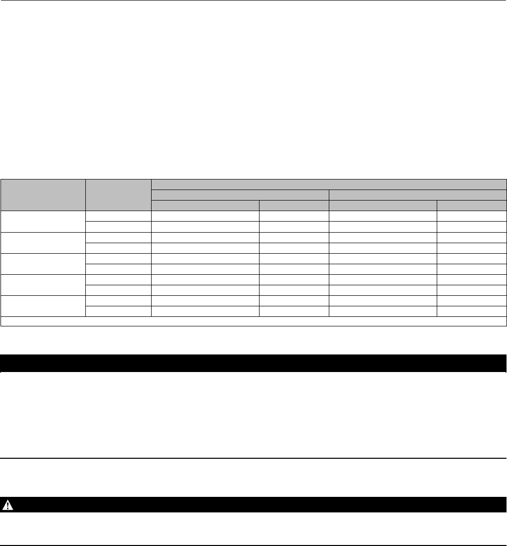
Figure 3. Live-Loaded Packing
39B4153-A
A6297-1
Typical HIGH-SEAL ULF Packing System Typical ENVIRO-SEAL Packing System
with PTFE Packing
Typical ENVIRO-SEAL Packing System
with Graphite ULF Packing
Typical ENVIRO-SEAL Packing System
with Duplex Packing
200
212
201
215
216
207
209
211
217
207
207
207
214
213
A6722
39B4612/A
Instruction Manual
D100394X012
EH (1-1/2x1 through 8x6)
December 2014
10
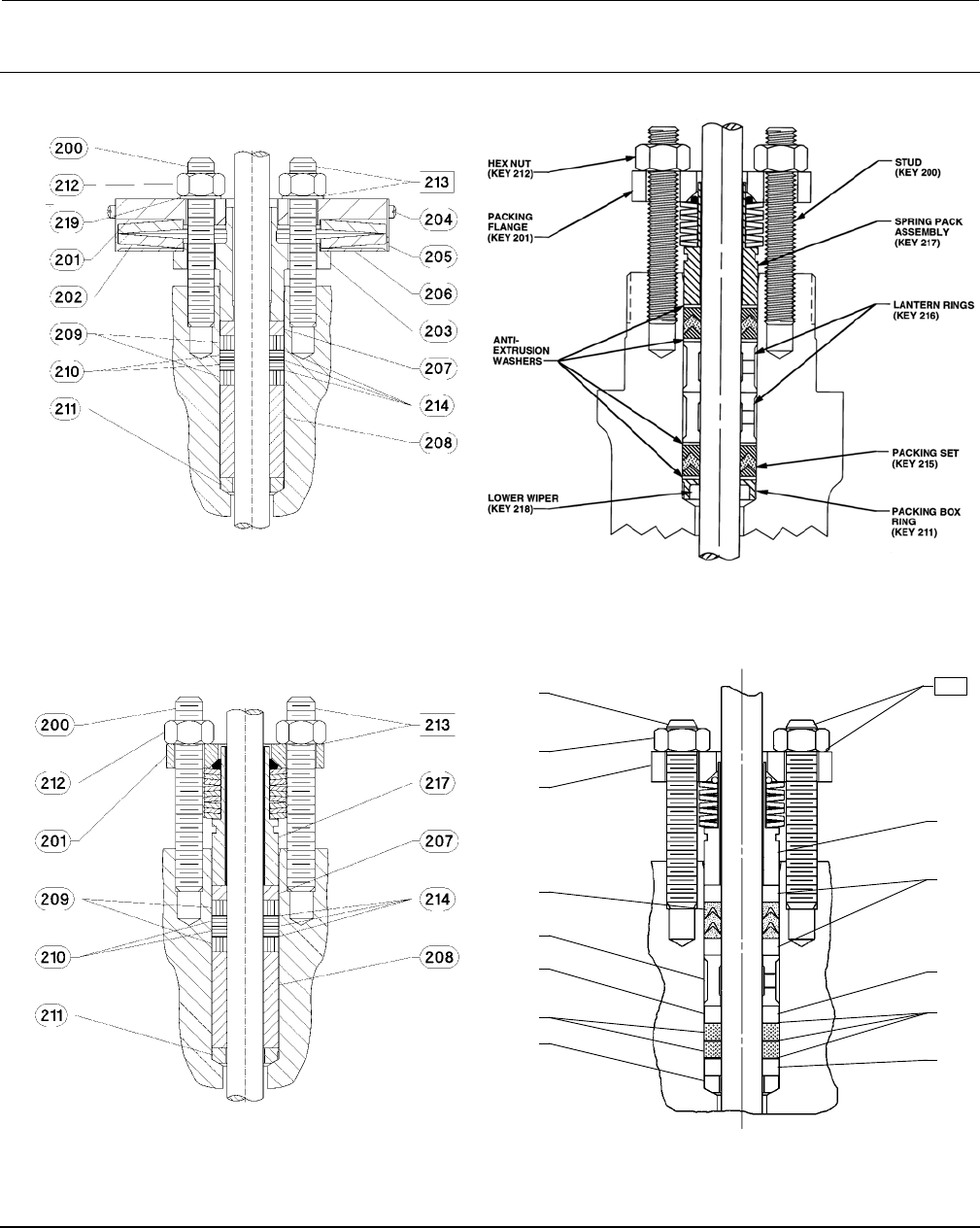
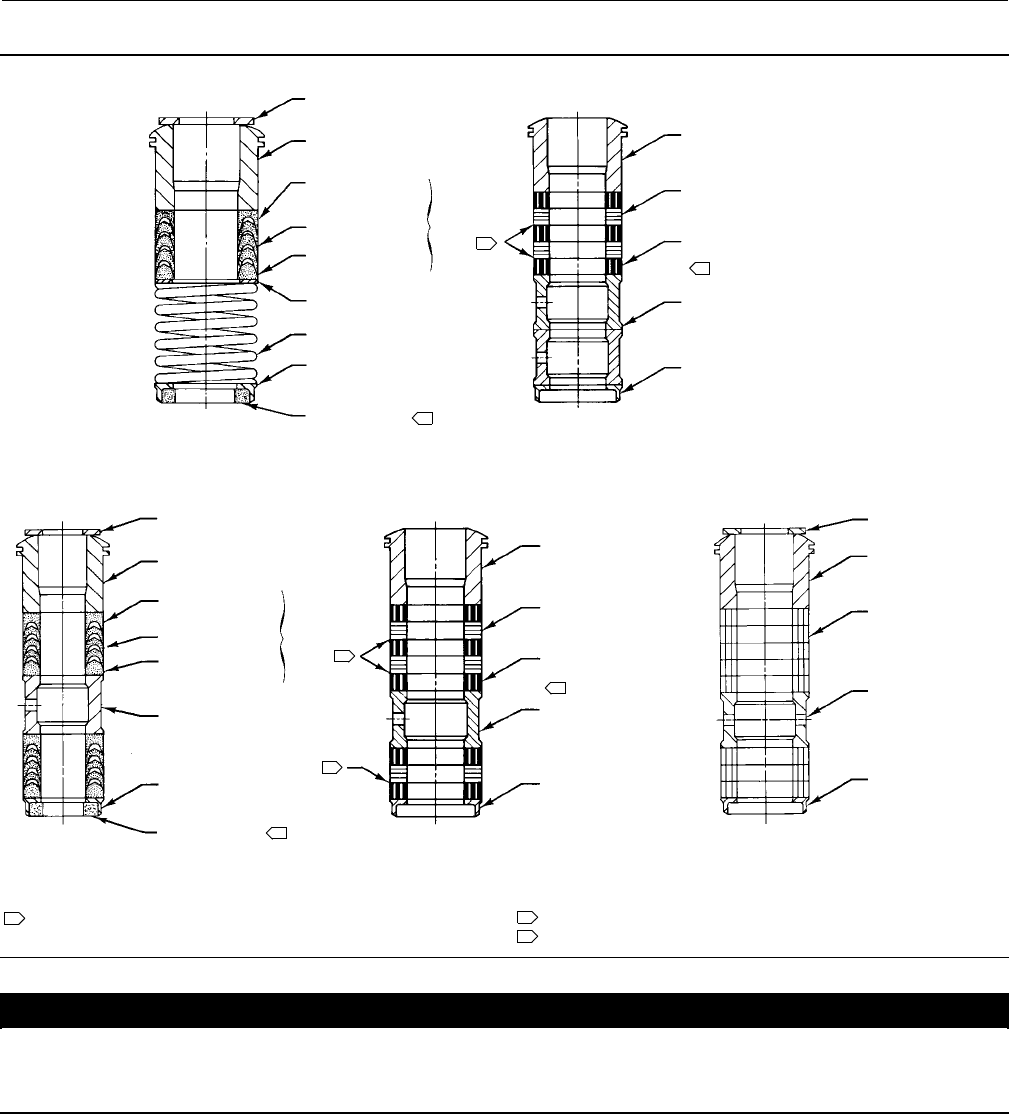
Figure 4. Packing Arrangements
UPPER WIPER (KEY 12)
PTFE V-RING
SINGLE PACKING
GRAPHITE RIBBON AND FILAMENT
SINGLE PACKING
12A8160-A
PACKING FOLLOWER
(KEY 13)
FEMALE ADAPTOR
(KEY 32)
V-RING (KEY 7)
MALE ADAPTOR
(KEY 31)
WASHER (KEY 10)
SPRING (KEY 8)
PACKING BOX RING
(KEY 11)
LOWER WIPER
(KEY 30)
PACKING FOLLOWER
(KEY 13)
PACKING BOX RING
(KEY 11)
GRAPHITE RIBBON
PACKING RING (KEY 7)
GRAPHITE FILAMENT
PACKING RING (KEY 7)
LANTERN RING
(KEY 8)
KEY 6
14A3412-C
1
2
3
1
1
PACKING FOLLOWER
(KEY 13)
PACKING BOX RING
(KEY 11)
GRAPHITE RIBBON
PACKING RING (KEY 7)
GRAPHITE FILAMENT
PACKING RING (KEY 7)
LANTERN RING
(KEY 8)
2
UPPER WIPER (KEY 12)
PACKING FOLLOWER
(KEY 13)
V-RING (KEY 7)
MALE ADAPTOR
(KEY 31)
LANTERN RING
(KEY 8)
PACKING BOX RING
(KEY 11)
LOWER WIPER
(KEY 30)
KEY 6
3
FEMALE ADAPTOR
(KEY 32)
UPPER WIPER (KEY 12)
PACKING FOLLOWER
(KEY 13)
LANTERN RING
(KEY 8)
PACKING BOX RING
(KEY 11)
PACKING RING
(KEY 7)
PTFE V-RING
DOUBLE PACKING
GRAPHITE RIBBON AND FILAMENT
DOUBLE PACKING
PTFE/COMPOSITION
DOUBLE PACKING
12A7839-A
Sht 1
14A3414-C 12A8163-A
NOTES:
0.102 mm (0.004 INCH) THICK SACRIFICIAL ZINC WASHERS.
USE ONLY ONE BELOW EACH GRAPHITE RIBBON RING.
HAS THE APPEARANCE OF A WOVEN OR BRAIDED RING.
INCLUDED IN KEY 6 PACKING SET.
12
3
C0637-1
CAUTION
All residual gasket material must be removed from the cage gasket surfaces. If the gasket surfaces are scored or damaged
during this process, smooth them by hand sanding with 360 grit paper using long, sweeping strokes. Failure to remove all
residual gasket material and/or burrs from the gasket surfaces will result in leakage.
6. Clean all gasket surfaces with a good quality degreaser. Remove all residual tin or silver from all gasket surfaces.
7. Cover the opening in the valve body to protect the gasket surface and to prevent foreign material from getting into
the valve body cavity.
8. Remove the packing flange nuts (key 5), packing flange (key 3), upper wiper (key 12), and packing follower (key 13,
figures 4 and 16). Carefully push out all the remaining packing parts from the valve side of the bonnet using a

Instruction Manual
D100394X012
EH (1-1/2x1 through 8x6)
December 2014
11
rounded rod or other tool that will not scratch the packing box wall. For extension bonnets, also remove the baffle
(key 2) and retaining ring (key 35).
9. Clean the packing box and the following metal packing parts: packing follower (key 13), packing box ring (key 11),
spring or lantern ring (key 8, figures 4 and 16), and, for single arrangements of PTFE V-ring packing only, special
washer (key 10, figures 4 and 16).
10. Inspect the valve stem threads for any sharp edges thatmightcutthepacking.Awhetstoneoremeryclothmay
be used to smooth the threads if necessary.
11. Remove the protective covering from the valve body cavity. Using new top and bottom cage gaskets (key 11,
figure 17, 18, or 20), place the cage into the valve body. Be sure the cage lugs are engaged in the corresponding
recesses of the seat ring retainer. Turn the cage clockwise until the lugs contact the seat ring retainer. Install the
plug, then slide the bonnet over the stem and onto the studs (key 13, figure 17, 18, or 20).
Note
The prelubricated hex nuts (key 14, figure 17, 18, or 20) referred to in step 12 can be identified by a black film coating on the nut
threads.
The proper bolting procedures in step 12 include--but are not limited to--ensuring that the bonnet stud threads are clean,
Belleville washers (if present) are installed in the correct orientation, and that the hex nuts are evenly tightened to the specified
torque values.
CAUTION
Failure to comply with good bonnet-to-body bolting practices and the torque values shown in table 8 may result in cage
crushing, cage diameter reduction, and/or bonnet deformation. Cheater bars or slug wrenches should not be used for this
procedure.
Hot torquing is not recommended.
Note
Stud(s) and nut(s) should be installed such that the manufacturer's trademark and material grade marking is visible, allowing easy
comparison to the materials selected and documented in the Emerson/Fisher serial card provided with this product.
WARNING
Personal injury or damage to equipment could occur if improper stud and nut materials or parts are used. Do not operate or
assemble this product with stud(s) and nut(s) that are not approved by Emerson/Fisher engineering and/or listed on the
serial card provided with this product. Use of unapproved materials and parts could lead to stresses exceeding the design
or code limits intended for this particular service. Install studs with the material grade and manufacturer's identification
mark visible. Contact your Emerson Process Management representative immediately if a discrepancy between actual
parts and approved parts is suspected.
12. Lubricate the stud threads and the faces of the hex nuts (key 14, figure 17, 18, or 20) with anti-seize lubricant (not
necessary if new factory prelubricated hex nuts are used). Replace the flat washers (key 29, figure 17, 18, 19, or 20)
if present. If the valve assembly includes Belleville washers (key 33, figure 19) install these onto the studs (key 14,
figure 19) with the concave side facing towards the valve body. Replace the hex nuts but do not tighten them.
Torquethenutsinacrisscrosspatterntonomorethanonefourthofthenominaltorquevaluespecifiedintable8.
Instruction Manual
D100394X012
EH (1-1/2x1 through 8x6)
December 2014
12
When all nuts are tightened to that torque value, increase the torque by one fourth of the specified nominal torque
and repeat the crisscross pattern. Repeat this procedure until all nuts are tightened to the specified nominal value.
Apply the final torque value again and, if any nut still turns, tighten every nut again.
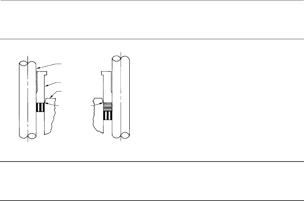
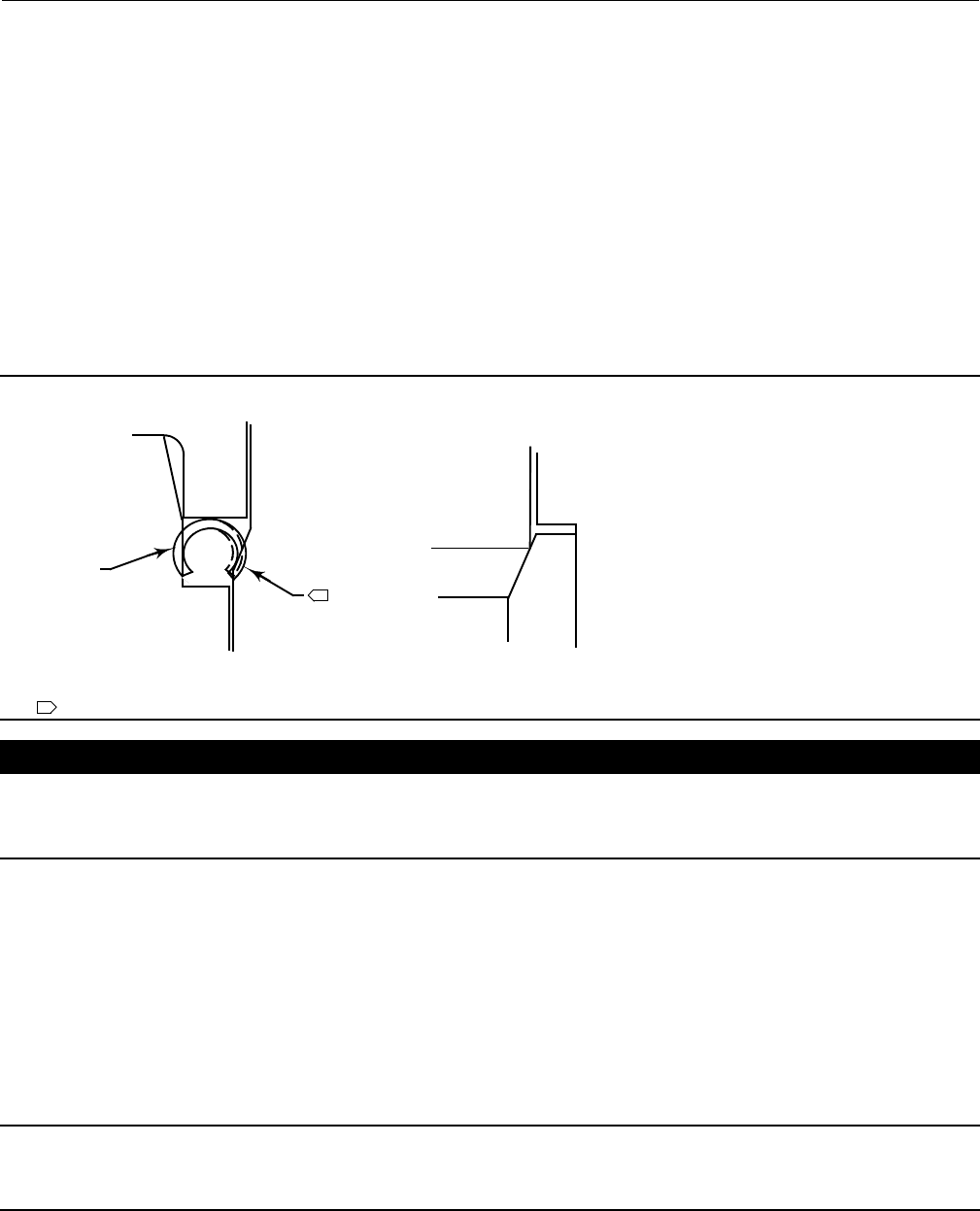
Figure 5. Installing Graphite Ribbon/Filament Packing Rings One at a Time
VALVE STEM
PACKING FOLLOWER
BONNET
TOP OF PACKING
RING EVEN WITH
BOTTOM OF
ENTRANCE
CHAMFER
INSTALLING
SECOND PACKING RING
A2207-2
INSTALLING
FIRST PACKING RING
Note
If graphite ribbon/filament packing rings are used, special procedures must be observed to prevent entrapping air between the
rings. Add the rings one at a time without forcing them below the chamfer of the packing box entrance chamber. As each
successive ring is added, the stack should not be pushed down more than the thickness of the added ring (figure 5).
13. Install new packing and the metal packing box parts according to the appropriate arrangement in figure 4. If
desired, packing parts may be pre-lubricated with a silicon base grease for easier installation. Slip a smooth-edged
pipe over the valve stem, and gently tamp each soft packingpartintothepackingbox,beingsurethatairisnot
trapped between adjacent soft parts. For a valve with extension bonnet, also install the baffle and retaining rings
(keys 2 and 35).
14. Slide the packing follower, wiper, and packing flange into position. Lubricate the packing flange studs (key 4) and
the faces of the packing flange nuts (key 5). Replace the packing flange nuts.
For spring-loaded PTFE V-ring packing, tighten the packing flange nuts until the shoulder on the packing follower (key
13) contacts the bonnet.
For other packing types, tighten the packing flange nuts to the maximum recommended torque shown in table 7.
Then, loosen the packing flange nuts, and retighten themtotherecommendedminimumtorqueshownintable7.
For ENVIRO-SEAL or HIGH-SEAL live-loaded packing, refer to the note at the beginning of the Maintenance section.
15. Mount the actuator on the valve body assembly, and reconnect the actuator and valve plug stems according to
the procedures in the appropriate actuator instruction manual.
Trim Removal
For C-seal construction, see the appropriate C-seal sections in this instruction manual.
Trim removal and replacement requires the use of a seat ring retainer tool (key 25). If specifically ordered, a tool is
supplied with a valve; but, the tool can also be ordered separately by referencing the tool part number in the Parts List.

Instruction Manual
D100394X012
EH (1-1/2x1 through 8x6)
December 2014
13
If desired, a tool can also be machined for a valve of specific size and valve class using the dimensions shown in figure
9. Machine the tool from a material listed in figure 9 or from a material with a yield strength of at least 827 MPa
(120,000 psi). Using a tool of lower strength material may result in damage to the seat ring retainer or valve body
threads.
Key numbers referenced in this procedure are shown in figure 17 for the EHD valve, figure 18 for the EHS valve, and
figure 20 for the EHT valve except where indicated.
1. Remove the actuator and bonnet by following steps 1 through 4 of the Replacing Packing procedure. Observe all
warnings and cautions.
2. Lift the valve stem and attached valve plug out of the valve body. If the valve plug is to be reused, tape or otherwise
protectthevalveplugstemandthevalveplug seating surface to prevent scratches.
3. Lift out the cage (key 2) and the top and bottom cage gaskets(key11).ForavalvewithCavitrolIIItwo-or
three-stage cage, also remove the O-ring (key 26, figure 21) that fits between the cage and the seat ring (key 6).
Constructions other than TSO trim
1. Use the seat ring retainer tool (figure 9) to remove the seat ring retainer (key 7) as follows:
a. Insert the tool into the valve body. Be certain the tool lugs are engaged in the corresponding recesses in the
retainer.
b. Use a power torque wrench or driver having torque capabilities equal to or greater than those shown in table 9.
Connect the torque wrench to an extensionifnecessary.Thetoolorextensionmustsnuglyfitthesquareholein
the seat ring retainer tool. Refer to figure 9 for square hole sizes.
c. Insert the tool or extension into the square hole in the seat ring retainer tool.
d. Use the bonnet studs (key 13) to prevent a power torque wrench from rotating.
CAUTION
Hold the torque wrench or driver at right angles to the seat ring retainer when applying torque. Tilting the tool or
extension while applying torque may cause the lugs on the seat ring retainer tool to suddenly disengage from the recesses
in the retainer, damaging the retainer and seat ring.
e. Unscrew and remove the seat ring retainer.
2. Remove the seat ring (key 6) and the seat ring gasket or O-ring (key 12).
3. Refer to the Valve Plug Maintenance procedure or to the Lapping Seats procedure.

Instruction Manual
D100394X012
EH (1-1/2x1 through 8x6)
December 2014
14
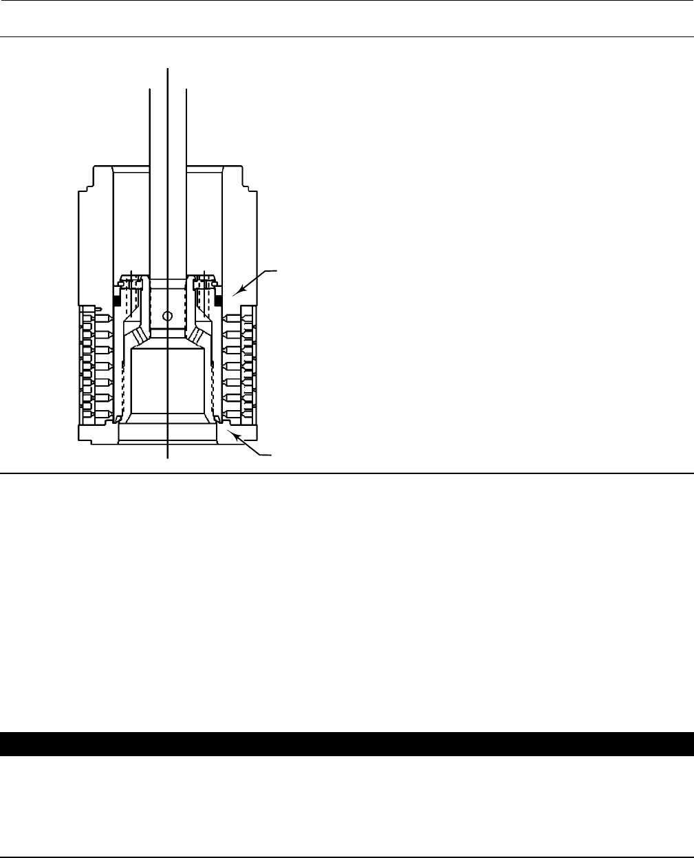
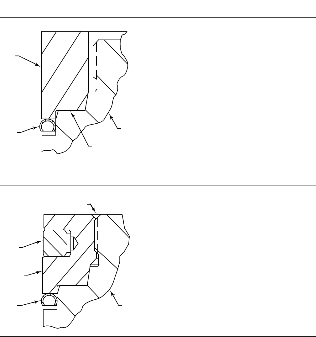
Figure 6. Detail of Protected Soft Seat
INNER PLUG
OUTER PLUG
CAGE
SEAT RING
PROTECTED SOFT SEAT
A7088
TSO Trim
Refer to figure 7.
1. Remove the retainer, backup ring, anti-extrusion rings, and piston ring.
2. Remove the set screws that lock the outer plug to the inner plug.
3. Using a strap wrench or similar tool, unscrew the outer plug from the inner plug. Do not damage the outer plug
guide surfaces.
4. Remove the protected soft seat seal (see figure 5).
5. Inspect the parts for damage and replace if needed.
6. Refer to the Valve Plug Maintenance procedure or to the Lapping Seats procedure.
Instruction Manual
D100394X012
EH (1-1/2x1 through 8x6)
December 2014
15
Figure 7. Typical Balanced TSO Trim
VALVE PLUG SEAL
PROTECTED SOFT SEAT
A7096
Valve Plug Maintenance
Key numbers used in this procedure are shown in figure 17 for the EHD valve, in figure 18 for the EHS valve, and in
figure 20 for the EHT valve.
1. With the valve plug (key 3) removed according to the Trim Removal procedure, proceed as appropriate:
For the EHD valve, the piston rings (key 8) are each in two sections; remove the sections from the grooves in the valve
plug.
For the EHS valve, proceed to step 2.
For the EHT valve, work the retaining ring (key 10) off the valve plug with a screwdriver. Carefully slide the backup ring
and seal ring (keys 9 and 8) off the valve plug. For an NPS 6 valve with a level D Whisper Trim III cage, also remove the
piston ring (key 30) from the grooves in the valve plug.
2. Toreplacethevalveplugstem(key4),driveoutthepin(key5),andunscrewthestemfromthevalveplug.
CAUTION
Never reuse an old stem with a new valve plug or reinstall a valve stem after it has been removed. Using an old stem with a
new plug requires drilling a new pin hole in the stem. This weakens the stem and may cause the stem to fail in service. If a
new valve plug is required, always order a valve plug, stem, and pin as an assembly. Specify the correct part number of each
of the three parts, but state that the parts are being ordered as an assembly.
A used valve plug may be reused with a new stem. An exceptionistheCavitrolIIIplug/stem assembly which must be
ordered and replaced as a unit.

Instruction Manual
D100394X012
EH (1-1/2x1 through 8x6)
December 2014
16
3. Thread the new stem into the valve plug and tighten it to the appropriate torque value given in table 10. Using the
valve plug pin hole as a guide, drill the pin hole through the stem. Refer to table 10 for drill sizes.
4. Drive in the pin to lock the assembly.
5. If it is necessary to lap the seating surfaces, complete the Lapping Seats procedure before installing the EHD piston
rings or the EHT seal ring. The Trim Replacement procedure provides piston ring and seal ring installation
instructions and valve reassembly instructions.
Lapping Seats
Key numbers referenced in this procedure are shown in figure 17 for the EHD valve, in figure 18 for the EHS valve, and
in figure 20 for the EHT valve unless otherwise indicated.
Seating surfaces of the valve plug (key 3) and the seat ring (key 6) can be lapped for improved shutoff. Use a good
quality lapping compound with a mixture that contains 280 to 600 grit. Apply the compound to the bottom of the
valveplug.Usethefollowingproceduretolaptheseatingsurfaces.
1. Install the following parts according to the instructions presented in the Trim Replacement procedure: seat ring
gasket or O-ring (key 12), seat ring (key 6), seat ring retainer (key 7), cage (key 2), cage gaskets (key 11), and if
used, the O-ring (key 26, figure 21).
2. Proceed as appropriate:
For an EHD or EHT valve, install the valve plug and stem assembly (keys 3 and 4)–without piston rings or seal ring (keys
8 and 30)–into the cage.
For an EHS valve, install the valve plug and stem assembly (keys 3 and 4) into the cage.
3. Install the bonnet (key 1, figure 16) over the valve stem, and secure the bonnet with four of the hex nuts (key 14).
4. Attach a handle, such as a piece of strap iron secured by stem locknuts, to the valve stem. Rotate the handle
alternately in each direction to lap the seats.
Note
To preserve the effects of lapping, do not change either the position of the seat ring in the valve body cavity or the position of the
cage on the seat ring after lapping the seating surfaces. If possible, clean the parts without disturbing their positions. If the parts
must be removed for cleaning, return them to the original positions.
5. After lapping, again disassemble as necessary, clean the seating surfaces, reassemble, and test for shutoff. Repeat
the lapping procedure if necessary.
Trim Replacement
After all trim maintenance has been completed, reassemble the valve by following the numbered steps below. Be
certain that all gasketed surfaces have been well cleaned. Key numbers referenced in this procedure are shown in
figure17fortheEHDvalve,infigure18fortheEHSvalve,andinfigure20fortheEHTvalve.
Instruction Manual
D100394X012
EH (1-1/2x1 through 8x6)
December 2014
17
Figure 8. Trim Surfaces Requiring Lubrication
SEAT RING RETAINER
A3583
SEAT RING GASKET OR O-RING
SEAT RING
VALVE BODY
LUBRICATION REQUIRED
1
1
1
CAUTION
Thoroughly clean the seat ring (key 6), seat ring retainer (key 7), and the retainer threads in the valve body with a
good-quality degreaser. Also clean all cage gasket surfaces. All residual gasket material must be removed from the cage
gasket surfaces and, in gasketed seat ring constructions, from the serrated valve body and seat ring gasket surfaces. If the
serrations are scored or damaged during this process, smooth them by hand sanding with 360 grit paper using long,
sweeping strokes. Failure to remove all residual gasket material and/or burrs from the seat ring, cage, and valve body
gasket surfaces will result in leakage.
Thoroughly lubricate the surfaces indicated in figure 8 with the appropriate lubricant shown in table 11. Be certain to
lubricate the mating surfaces of both parts involved (i.e., lubricate the threads on the seat ring retainer and the threads in
the valve body; lubricate the mating surfaces of the seat ring retainer and seat ring).
Failure to lubricate as described may cause galling and improper gasket or O-ring (key 12) loading that may result in
leakage.
1. For gasketed seat ring constructions, install the seat ring gasket (key 12) into the valve body. For O-ring seat ring
constructions, install the O-ring (key 12) into the groove on the underside of the seat ring (key 6). Install the seat
ring (key 6). Screw in the seat ring retainer (key 7). Use the seat ring retainer tool (figure 9) to tighten the seat ring
retainer as follows:
a. Insert the tool into the valve body. Be certain the tool lugs are engaged in the corresponding recesses in the
retainer.
b. Use a power torque wrench or driver having torque capabilities equal to or greater than those shown in table 9.
Connect the torque tool to an extension if necessary. The tool or extension must snugly fit the square hole in the
seat ring retainer tool. Refer to figure 9 for square hole sizes.
c. Insert the tool or extension into the square hole in the seat ring retainer tool.
d. Use the stud bolts (key 13) to prevent a power torque wrench from rotating.
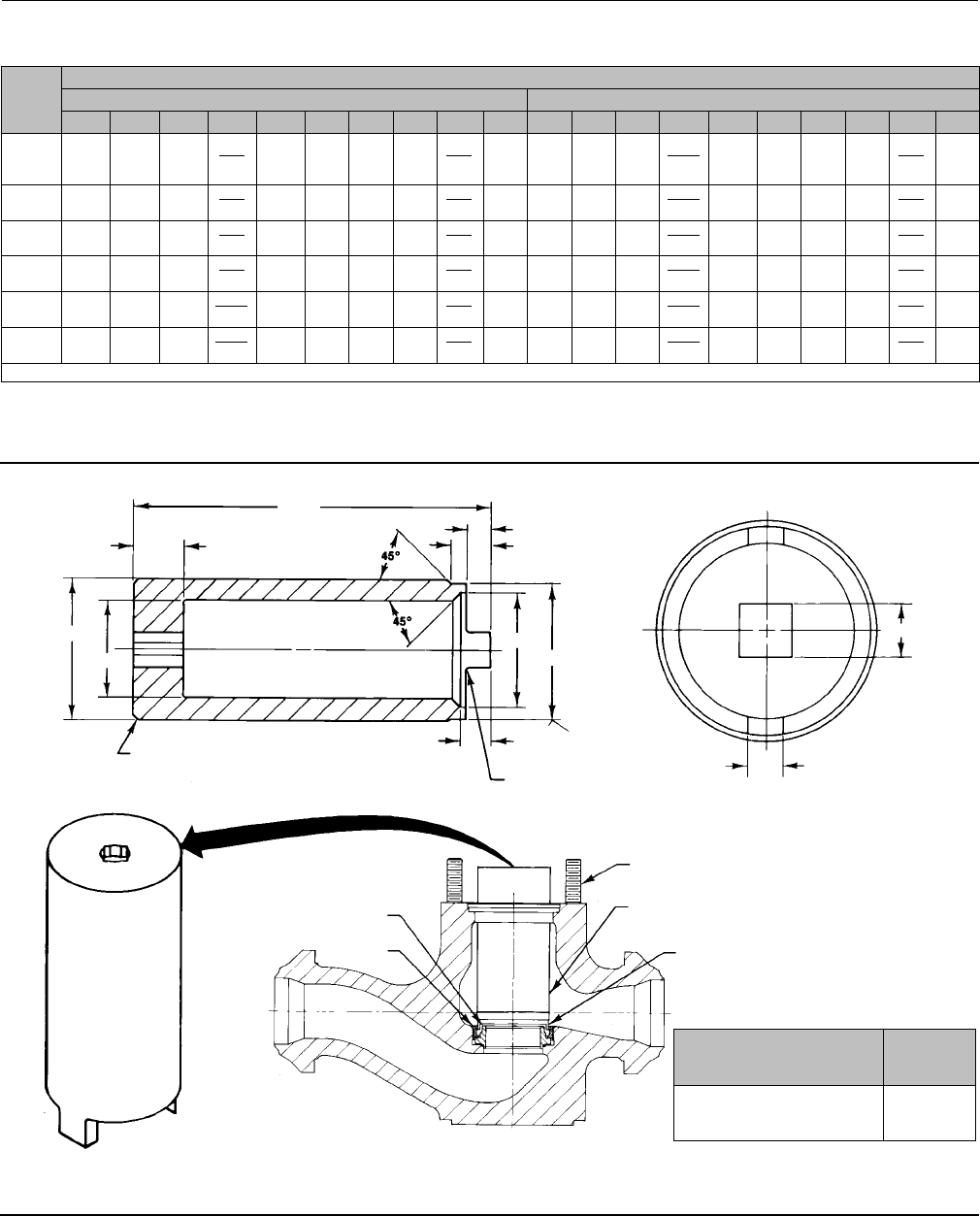
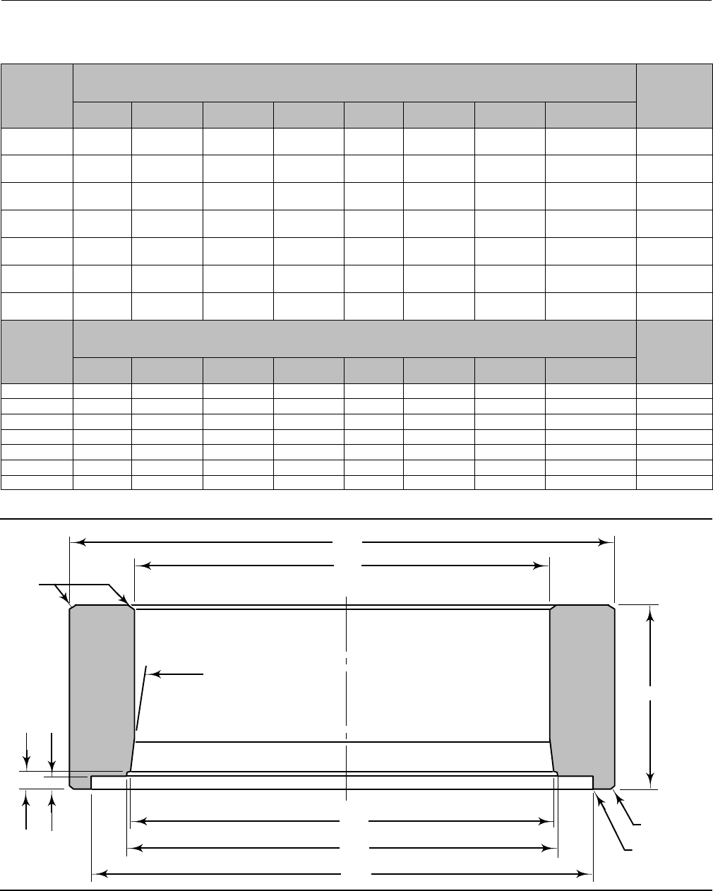
Figure 9. Information for Machining and Use of Seat Ring Retainer Tool
DIM E
DIM G
DIM F
0.0625 R
DIA D
DIA C
125
DIM H
CHAM
DIA A
DIA B
0.75 MIN
1.625 MAX
DIM J
2 LUGS EQUALLY SPACED
DIM K
STUD BOLT
SEAT RING
SEAT RING
RETAINER
SEAT RING
RETAINER TOOL
TOOL LUG
TOOL INSTALLATIONSEAT RING RETAINER TOOL
3MC2169-E
35A1086-A
26A5130-A
B1465-2
Instruction Manual
D100394X012
EH (1-1/2x1 through 8x6)
December 2014
18
VALVE
SIZE,
NPS/
RATING
TOOL DIMENSIONS
mm Inches
A B C D(1) E F G H J(1) K A B C D(1) E F G H J(1) K
1-1/2
x1/
CL2500
50.8 31.8 34.1 46.4
45.9 111.3 11.2 7.9 11.2 12.4
12.2 19.1 2.00 1.25 1.34 1.827
1.807 4.38 0.44 0.31 0.44 0.49
0.48 0.75
2x1/
CL2500 50.8 31.8 34.1 46.4
45.9 111.3 11.2 7.9 11.2 12.4
12.2 19.1 2.00 1.25 1.34 1.827
1.807 4.38 0.44 0.31 0.44 0.49
0.48 0.75
3x2/
CL2500 69.9 50.8 53.0 67.1
66.5 150.9 12.7 9.7 12.7 12.4
12.2 19.1 2.75 2.00 2.12 2.640
2.620 5.94 0.50 0.38 0.50 0.49
0.48 0.75
3,4x3/
CL2500 90.5 65.0 74.6 86.1
85.6 185.7 12.7 9.7 12.7 18.8
18.5 25.4 3.56 2.36 2.94 3.390
3.370 7.31 0.50 0.38 0.50 0.74
0.73 1.00
4,6x4/
CL2500 117.3 88.9 91.9 108.3
107.8 195.3 14.2 10.4 14.2 25.1
24.9 25.4 4.62 3.50 3.62 4.265
4.245 7.69 0.56 0.41 0.56 0.99
0.98 1.00
6,8x6/
CL2500 177.8 130.0 134.9 156.0
155.4 254.0 14.2 10.4 14.2 25.1
24.9 38.1 7.00 5.12 5.31 6.140
6.120 10.00 0.56 0.41 0.56 0.99
0.96 1.50
1. D and J dimensions list maximum and minimum values.
Materials for Machining Tool
Recommended
Materials
Minimum
Rockwell
Hardness
416 stainless steel
17-4PH stainless steel
4100 Series heat-treated steel
28
36
31

Instruction Manual
D100394X012
EH (1-1/2x1 through 8x6)
December 2014
19
Table 9. Recommended Torque for Installing Seat Ring Retainer
VALVE
SIZE,
NPS
VALVE
BODY
RATING
TORQUE
For All Valves with
Gasketed Seat Ring
Construction Except
Those with
Cavitrol III Cage
For All Valves with
O-Ring Seat Ring
Construction(1) or for
Sour Gas Service
For Valve with 2-Stage
Cavitrol III Cage and
Gasketed Seat Ring
Construction
For Valve with 3-Stage
Cavitrol III Cage and
Gasketed Seat Ring
Construction
NSmLbfSFt NSmLbfSFt NSmLbfSFt NSmLbfSFt
1, 1-1/2x1, 2x1 CL1500 509 375 68 50 339 250 --- ---
CL2500 373 275 68 50 203 150 --- ---
2, 3x2 CL1500 1187 875 136 100 881 650 678 500
CL2500 848 625 102 75 542 400 407 300
3, 4x3 CL1500 2203 1625 271 200 1491 1100 1356 1000
CL2500 1593 1175 203 150 949 700 678 500
4, 6x4 CL1500 3118 2300 373 275 2712 2000 2373 1750
CL2500 2373 1750 271 200 2373 1750 1695 1250
6, 8x6 CL1500 6780 5000 780 575 6101 4500 5423 4000
CL2500 5017 3700 576 425 4745 3500 4745 3500
1. Includes valves with Cavitrol III trim.
Table10.ValveStemConnectionTorqueandDrillSizeforPinHole
VALVE SIZE,
NPS
VALVE STEM
DIAMETER VALVE BODY
RATING VALVE
VALVE STEM
CONNECTION TORQUE
(MINIMUM - MAXIMUM)
DRILL SIZE
FOR PIN
mm Inches NSmLbfSFt Inches
1, 1-1/2x1, 2x1 12.7 1/2 CL1500, CL2500 EHS 81 - 115 60 - 85 1/8
19.1 3/4 CL1500 EHS 237 - 339 175 - 250 3/16
2, 3x2
12.7 1/2 CL1500, CL2500 EHD, EHS, EHT 81 - 115 60 - 85 1/8
19.1 3/4 CL1500, CL2500 EHS 237 - 339 175 - 250 3/16
EHD, EHT 237 - 339 175 - 250 1/8
25.4 1CL1500, CL2500 EHS 420 - 481 310 - 355 1/4
3, 4x3
12.7 1/2 CL1500, CL2500 EHD, EHS, EHT 81 - 115 60 - 85 1/8
19.1 3/4 CL1500, CL2500 EHD, EHS, EHT 237 - 339 175 - 250 3/16
25.4 1
CL1500, CL2500 EHS 420 - 481 310 - 355 1/4
CL1500 EHD, EHT 420 - 481 310 - 355 1/4
CL2500 EHD, EHT 420 - 481 310 - 355 3/16
4, 6x4 19.1 3/4 CL1500, CL2500 EHD, EHS, EHT 237 - 339 175 - 250 3/16
25.4 1CL1500, CL2500 EHD, EHS, EHT 420 - 481 310 - 355 1/4
6, 8x6
19.1 3/4 CL1500, CL2500 EHD, EHS, EHT 237 - 339 175 - 250 3/16
25.4 1CL1500, CL2500 EHD, EHS, EHT 420 - 481 310 - 355 1/4
31.8 1-1/4 CL1500, CL2500 EHD, EHS, EHT 827 - 908 610 - 670 1/4
50.8 2CL1500, CL2500 EHD, EHT
Contact factory for
torque values and
installation procedure
3/8
Table 11. Seat Ring and Seat Ring Retainer Lubricants
VALVE BODY
MATERIAL
SEAT RING
MATERIAL LUBRICANT
WCC, WC9, C5, or LCC steel S41600 (416 stainless steel) Lithium grease, dry film lubricant, or anti-seize lubricant
R30006 (Alloy 6) Anti-seize lubricant
CF8M (316 stainless steel) R30006 Dry film lubricant or anti-seize lubricant

Instruction Manual
D100394X012
EH (1-1/2x1 through 8x6)
December 2014
20
CAUTION
Hold the torque wrench at right angles to the seat ring retainer when applying torque. Tilting the tool and extension while
applying torque may cause the lugs on the seat ring retainer tool to suddenly disengage from the recesses in the retainer,
damaging the retainer and seat ring.
e. Tighten the seat ring retainer to the torque shown in table 9.
Note
Some cages have one large window and several small windows. In step 2, install a cage that has different size windows so that the
largest window faces toward the process outlet for a flow-down and toward the process inlet for a flow-up valve. Though it may
not be possible to align the large window directly opposite the inlet or outlet, orient the window in the appropriate direction as
much as possible. Incorrect orientation of cage windows causes a reduction of capacity.
2. Proceed as appropriate:
For a valve with a Cavitrol III cage, slidetheO-ring(key26,figure21)overtheseatring(key6)andagainstthe
shoulder in the outer diameter of the seat ring. Install the lower gasket (key 11) between the valve body and cage (key
2),andinstallthecage.Becertainthelugsonthebottomofthecageengagethecorrespondingslotsintheseatring
retainer.
Forallothervalves,install the lower gasket (key 11) between the valve body and cage (key 2), and install the cage. Be
certain the lugs on the bottom of the cage engage the corresponding slots in the seat ring retainer.
Note
Rotate the cage clockwise by hand as much as possible once the cage lugs engage the slots in the seat ring retainer. Failure to do
so may result in leakage at the seat ring to valve body seal.
Constructions other than TSO trim
1. To install the piston rings and seal rings (keys 8 and 30), proceed as appropriate:
For an EHD valve (figure 17), if it is necessary to install new piston rings, the replacement piston rings will arrive in one
piece. Use a vise with smooth or taped jaws to break a replacement piston ring into halves. Place the new ring in the
vise so that the jaws compress the ring into an oval. Compress the ring slowly until the ring snaps on both sides. If one
side snaps first, do not try to tear or cut the other side. Instead, keep compressing until the other side snaps. The
piston ring can also be fractured by scoring and snapping over a hard surface such as a table edge. Sawing or cutting is
not recommended.
Remove any protective tape or covering from the valve plug and stem assembly, and set it on a protective surface.
Then, place the piston ring in the piston ring groove with the fractured ends matched.
For an EHT valve (figure 20), install the seal ring (key 8) onto the valve plug (key 3). Install the ring with the open side
facing the seat ring end of the valve plug for flow-down applications (view A of figure 20) or with the open side facing
the valve plug stem end of the valve plug for flow-up applications. Slide the backup ring (key 9) onto the valve plug.

Instruction Manual
D100394X012
EH (1-1/2x1 through 8x6)
December 2014
21
Secure with the retaining ring (key 10). For an NPS 6 valve with a level D Whisper Trim III cage, reinstall the piston ring
(key 30) following the instructions given in the paragraph immediately preceding.
2. Install the valve plug into the cage.
TSO Trim
Refer to figure 7.
1. Thread the outer plug onto the inner plug until the parts seat metal to metal, using a strap wrench or similar tool
that will not damage the outer plug guide surfaces.
2. Mark the top of the inner plug and outer plug with alignment marks in the assembled position.
3. Disassemble the outer plug from the inner plug and install the seal over the inner plug, so that the seal rests below
the threaded area.
4. Thread the outer plug onto the inner plug and tighten with a strap wrench or similar tool until the alignment marks
line up. This will ensure that the plug parts are metal to metal and the seal is compressed properly. Do not damage
the outer plug guide surfaces.
5. Install set screws centering the inner plug in the outer plug and torque to 11 NSm(8lbfSft).
6. Assemble the piston ring, anti-extrusion rings, backup ring, and retainer.
All Constructions
1. Install the top cage gasket (key 11) on the cage.
2. Install the bonnet over the valve stem and onto the valve body.
Note
The prelubricated hex nuts (key 14, figure 17, 18, or 20) referred to in step 3 can be identified by a black film coating on the nut
threads.
The proper bolting procedures in step 3 include--but are not limited to--ensuring that the bonnet stud threads are clean, Belleville
washers (if present) are installed in the correct orientation, and that the hex nuts are evenly tightened to the specified torque
values.
CAUTION
Failure to comply with good bonnet-to-body bolting practices and the torque values shown in table 8 may result in cage
crushing, cage diameter reduction, and/or bonnet deformation. Cheater bars or slug wrenches should not be used for this
procedure.
Hot torquing is not recommended.
Note
Stud(s) and nut(s) should be installed such that the manufacturer's trademark and material grade marking is visible, allowing easy
comparison to the materials selected and documented in the Emerson/Fisher serial card provided with this product.
WARNING
Personal injury or damage to equipment could occur if improper stud and nut materials or parts are used. Do not operate or
assemble this product with stud(s) and nut(s) that are not approved by Emerson/Fisher engineering and/or listed on the

Instruction Manual
D100394X012
EH (1-1/2x1 through 8x6)
December 2014
22
serial card provided with this product. Use of unapproved materials and parts could lead to stresses exceeding the design
or code limits intended for this particular service. Install studs with the material grade and manufacturer's identification
mark visible. Contact your Emerson Process Management representative immediately if a discrepancy between actual
parts and approved parts is suspected.
3. Lubricate the stud threads and the faces of the hex nuts (key 14, figure 17, 18, or 20) with anti-seize lubricant (not
necessary if new factory prelubricated hex nuts are used). Replace the flat washers (key 29, figure 17, 18, 19, or 20)
if present. If the valve assembly includes Belleville washers (key 33, figure 19) install these onto the studs (key 14,
figure 19) with the concave side facing towards the valve body. Replace the hex nuts but do not tighten them.
Torquethenutsinacrisscrosspatterntonomorethanonefourthofthenominaltorquevaluespecifiedintable8.
When all nuts are tightened to that torque value, increase the torque by one fourth of the specified nominal torque
and repeat the crisscross pattern. Repeat this procedure until all nuts are tightened to the specified nominal value.
Apply the final torque value again and, if any nut still turns, tighten every nut again.
4. Install new packing and packing box parts per steps 13 and 14 of the Replacing Packing procedure. Be certain to
observe the note given prior to step 13 of that procedure.
5. Mount the actuator by following the procedures in the actuator instruction manual. Check for packing leakage as
the valve is being put into service. Retorque the packing flange nuts as required (see table 7).
Retrofit: Installing C-seal Trim
Note
Additional actuator thrust is required for a valve with C-seal trim. When installing C-seal trim in an existing valve, contact your
Emerson Process Management sales office for assistance in determining new actuator thrust requirements.
Figure 10. Fisher EHD with C-seal Trim
FLOW DOWN FLOW UP
VIEW A
37B1047-A
Assemble the new valve plug/retainer assembly (with C-seal plug seal) using the following instructions:

Instruction Manual
D100394X012
EH (1-1/2x1 through 8x6)
December 2014
23
CAUTION
To avoid leakage when the valve is returned to service, use appropriate methods and materials to protect all sealing
surfaces of the new trim parts while assembling the individual parts and during installation in the valve body.
1. Apply a suitable high-temperature lubricant to the inside diameter of the C-seal plugseal.Also,lubricatethe
outside diameter of the valve plug where the C-seal plug seal must be pressed into the proper sealing position
(figure 10).
2. Orient the C-seal plug seal for correct sealing action based on the process fluid flow direction through the valve.
DThe open interior of the C-seal plug seal must face up in a valve with flow-up construction (figure 10).
DThe open interior of the C-seal plug seal must face down in a valve with flow-down construction (figure 10).
Note
An installation tool must be used to properly position the C-seal plug seal on the valve plug. A tool is available as a spare part from
Emerson Process Management or a tool could be manufactured following the dimensions given in figure 11.
3. Place the C-seal plug seal over the top of the valve plug and press the C-seal plug seal onto the plug using the C-seal
installation tool. Carefully press the C-seal plug seal onto the plug until the installation tool contacts the horizontal
referencesurfaceofthevalveplug(figure12).
4. Apply a suitable high-temperature lubricant to the threads on the plug. Then, place the C-seal retainer onto the
plug and tighten the retainer using an appropriate tool such as a strap wrench.
5. Using an appropriate tool such as a center punch, stake thethreadsontopofthepluginoneplace(figure13)to
secure the C-seal retainer.
6. Install the new plug/retainer assembly with C-seal plug seal on the new stem following the appropriate instructions
in the Trim Replacement section of this manual.
7. Install piston rings by following instructions in the Trim Replacement section of this manual.
8. Remove the existing valve actuator and bonnet following the appropriate instructions in the Replacing Packing
section of this manual.
CAUTION
Do not remove the existing valve stem from the valve plug unless you are planning to replace the valve stem.
Never reuse an old valve stem with a new plug or reinstall a valve stem after it has been removed. Replacing a valve stem
requires drilling a new pin hole in the stem. This drilling weakens the stem and may cause failure in service.
However, a used valve plug may be reused with a new valve stem. An exception is the Cavitrol III plug/stem assembly which
must be ordered and replaced as a unit.
9. Remove the existing valve stem and plug, cage, and seat ring from the valve body following the appropriate
instructions in the Trim Removal section of this manual.
10. Replace all gaskets according to appropriate instructions in the Trim Replacement section of this manual.
11. Install the new seat ring, cage, valve plug/retainer assembly, and stem into the valve body and completely
reassemble the valve package following the appropriate instructions in the Trim Replacement section of this
manual.
Instruction Manual
D100394X012
EH (1-1/2x1 through 8x6)
December 2014
24
FOR VALVE
PLUGS
FITTING
PORT SIZE
(Inches)
DIMENSIONS, mm
(See Drawing Below) Part Number
(To Order
A Tool)
A B C D E F G H
2.875 82.55 52.324 -
52.578 4.978 - 5.029 3.708 - 3.759 41.148 52.680 -
52.781
55.118 -
55.626 70.891 - 71.044 24B9816X012
3.4375 101.6 58.674 -
58.928 4.978 - 5.029 3.708 - 3.759 50.8 61.011 -
61.112
63.449 -
63.957 85.166 - 85.319 24B5612X012
3.625 104.394 65.024 -
65.278 4.978 - 5.029 3.708 - 3.759 50.8 68.936 -
69.037
71.374 -
71.882 89.941 - 90.094 24B3630X012
4.375 125.984 83.439 -
83.693 4.978 - 5.029 3.708 - 3.759 50.8 87.351 -
87.452
89.789 -
90.297 108.991 - 109.144 24B3635X012
5.375 142.748 100.076 -
100.33 4.978 - 5.029 3.708 - 3.759 45.974 103.835 -
103.937
106.274 -
106.782 128.219 - 128.372 23B9193X012
7184.15 141.376 -
141.630 4.978 - 5.029 3.708 - 3.759 60.198 145.136 -
145.237
147.574 -
148.082 169.520 - 169.672 23B9180X012
8209.55 166.776 -
167.030 4.978 - 5.029 3.708 - 3.759 55.88 170.536 -
170.637
172.974 -
173.482 194.920 - 195.072 24B9856X012
FOR VALVE
PLUGS
FITTING
PORT SIZE
(Inches)
Dimensions, Inches
(See Drawing Below) Part Number
(To Order
A Tool)
A B C D E F G H
2.875 3.25 2.060 - 2.070 0.196 - 0.198 0.146 - 0.148 1.62 2.074 - 2.078 2.170 - 2.190 2.791 - 2.797 24B9816X012
3.4375 4.00 2.310 - 2.320 0.196 - 0.198 0.146 - 0.148 2.00 2.402 - 2.406 2.498 - 2.518 3.353 - 3.359 24B5612X012
3.625 4.11 2.560 - 2.570 0.196 - 0.198 0.146 - 0.148 2.00 2.714 - 2.718 2.810 - 2.830 3.541 - 3.547 24B3630X012
4.375 4.96 3.285 - 3.295 0.196 - 0.198 0.146 - 0.148 2.00 3.439 - 3.443 3.535 - 3.555 4.291 - 4.297 24B3635X012
5.375 5.62 3.940 - 3.950 0.196 - 0.198 0.146 - 0.148 1.81 4.088 - 4.092 4.184 - 4.204 5.048 - 5.054 23B9193X012
77.25 5.566 - 5.576 0.196 - 0.198 0.146 - 0.148 2.37 5.714 - 5.718 5.810 - 5.830 6.674 - 6.680 23B9180X012
88.25 6.566 - 6.576 0.196 - 0.198 0.146 - 0.148 2.20 6.714 - 6.718 6.810 - 6.830 7.674 - 7.680 24B9856X012
Figure 11. C-seal Plug Seal Installation Tool
45X 1.524 (0.06)
A
B
8-9
D
C
F
G
H
E
BREAK SHARP
CORNER
45X 0.254 (0.01)
MAX
45X 0.508 (0.02)
A6777
mm (inch)

Instruction Manual
D100394X012
EH (1-1/2x1 through 8x6)
December 2014
25
CAUTION
To avoid excessive leakage and seat erosion, the valve plug must be initially seated with sufficient force to overcome the
resistance of the C-seal plug seal and contact the seat ring. You can correctly seat the valve plug by using the same force
calculated for full load when sizing your actuator. With no pressure drop through the valve, this force will adequately drive
the valve plug to the seat ring, thus giving the C-seal plug seal a predetermined permanent set. Once this is done, the
plug/retainer assembly, the cage, and the seat ring become a matched set.
12. With full actuator force applied and the valve plug fully seated, align the actuator travel indicator scale with the
lower end of valve travel. Refer to the appropriate actuator instruction manual for information on this procedure.
Replacement of Installed C-seal Trim
Trim Removal (C-seal Constructions)
1. Remove the valve actuator and bonnet following the appropriate instructions in the Replacing Packing section of
this manual.
CAUTION
To avoid leakage when the valve is returned to service, use appropriate methods and materials to protect all sealing
surfaces of the trim parts during maintenance.
Use caution when removing piston ring(s) and C-seal plug seal to avoid scratching any sealing surface.
CAUTION
Do not remove the valve stem from the plug/retainer assembly unless you are planning to replace the valve stem.
Never reuse an old valve stem with a new plug or reinstall a valve stem after it has been removed. Replacing a valve stem
requires drilling a new pin hole in the stem. This drilling weakens the stem and may cause failure in service.
However, a used valve plug may be reused with a new valve stem. An exception is the Cavitrol III plug/stem assembly which
must be ordered and replaced as a unit.
2. Remove the plug/retainer assembly (with C-seal plug seal), cage, and seat ring from the valve body following the
appropriate instructions in the Trim Removal section of this manual.
3. Locate the staked thread on top of the valve plug (figure 13). The staked thread secures the retainer. Use a drill with
a 1/8-inch bit to drill out the staked area of the thread. Drill approximately 1/8-inch into the metal to remove the
staking.
4. Locate the break between sections of the piston ring(s). Using an appropriate tool such as a flat-blade screwdriver,
carefully pry out the piston ring(s) fromthegroove(s)intheC-sealretainer.
5. After removing the piston ring(s), locate the 1/4-inch diameter hole in the groove. In a retainer with two piston ring
grooves,theholewillbefoundintheuppergroove.
Instruction Manual
D100394X012
EH (1-1/2x1 through 8x6)
December 2014
26
Figure 12. Installing the C-seal Plug Seal Using the Installation Tool
NOTE:
PRESS INSTALLATION TOOL OVER VALVE PLUG UNTIL THE TOOL CONTACTS THE HORIZONTAL REFERENCE SURFACE OF THE VALVE PLUG.
C-seal
METAL
PLUG
SEAL
INSTALLATION
TOOL
A6778
VALVE
PLUG
HORIZONTAL
REFERENCE
SURFACE
FLOW DOWN
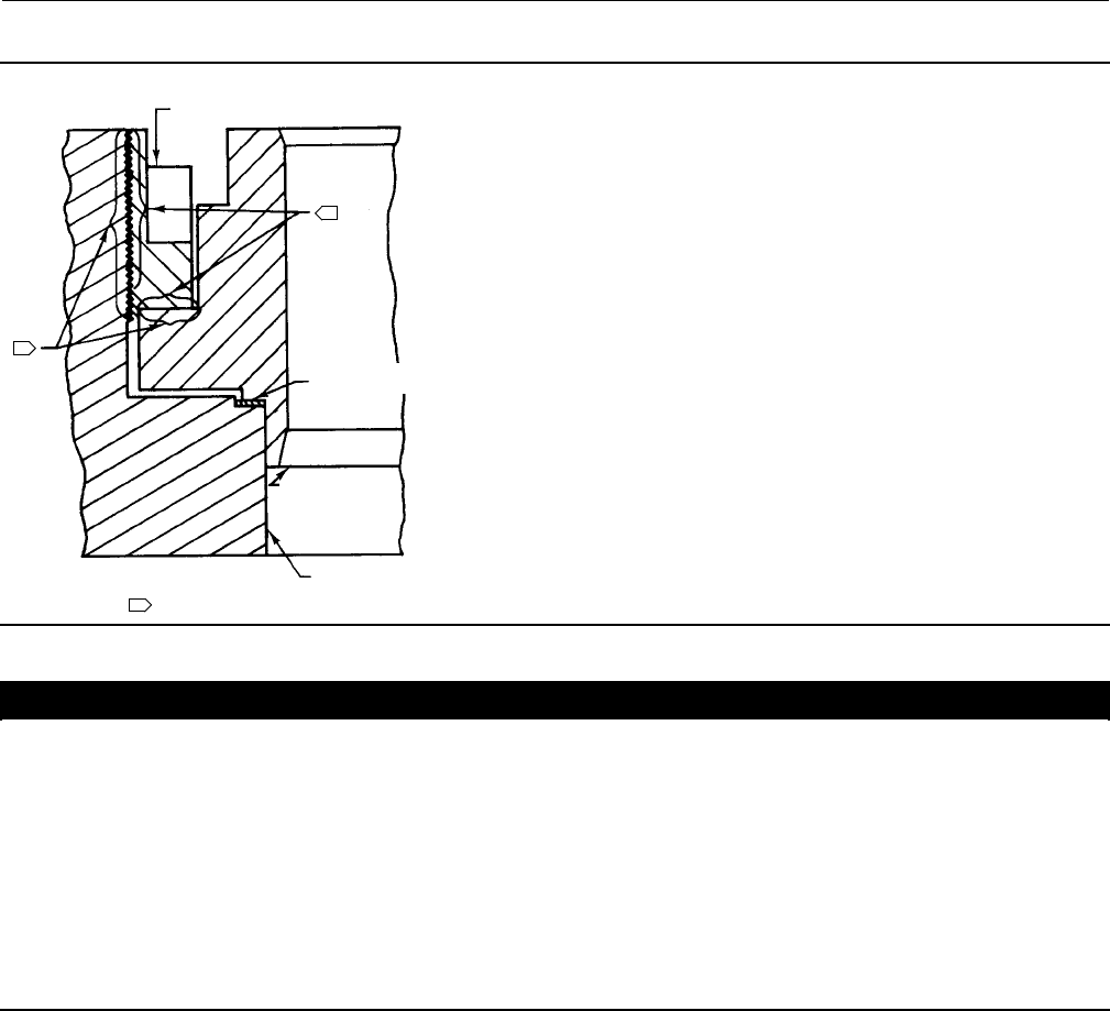
Figure 13. Stake the Threads of the C-seal Retainer
C-seal
METAL
PLUG
SEAL
VALVE
PLUG
FLOW DOWN
PISTON
RING
RETAINER
DEFORM THREAD TO
STAKE C-seal RETAINER
A6779
6. Selectanappropriatetoolsuchasapunchandplacethetipofthetoolintotheholewiththebodyofthetoolheld
tangent to the outside diameter of the retainer. Strike the tool with a hammer to rotate the retainer and free it from
thevalveplug.Removetheretainerfromtheplug.
7. Use an appropriate tool such as a flat-blade screwdriver to pry the C-seal plug seal off the plug. Use caution to avoid
scratches or other damage to the sealing surfaces where the C-seal plug seal makes contact with the valve plug
(figure 14).
8. Inspect the lower seating surface where the valve plug contacts the seat ring for wear or damage which would
prevent proper operation of the valve. Also, inspect the upperseatingsurfaceinsidethecagewheretheC-sealplug
Instruction Manual
D100394X012
EH (1-1/2x1 through 8x6)
December 2014
27
seal contacts the cage, and inspect the sealing surface where the C-seal plug seal makes contact with the plug
(figure 14).
9. Replace or repair trim parts according to the following procedure for lapping metal seats, remachining metal seats,
or other valve plug maintenance procedures as appropriate.
Lapping Metal Seats (C-seal Constructions)
Before installing a new C-seal plug seal, lap the lower seating surface (valve plug to seat ring, figure 14) following
appropriate procedures in the Lapping Seats section of this manual.
Remachining Metal Seats (C-seal Constructions)
See figure 15. A valve plug with a C-seal metal plug seal features two seating surfaces. One seating surface is found
wherethevalveplugcontactstheseatring. The second seating surface is found where the C-seal plug seal contacts
the upper seating surface in the cage. If you machine the seats on the seat ring and/or plug, you must machine an
equal dimension from the seating area in the cage.
Figure 14. Lower (Valve Plug to Seat Ring) and Upper (C-seal Plug Seal to Cage) Seating Surfaces
C-seal METAL
PLUG SEAL
RETAINER
CAGE
VALVE PLUG
NOTE:
UPPER SEATING SURFACE IS THE AREA OF CONTACT BETWEEN THE C-seal METAL PLUG SEAL AND THE CAGE.
PLUG
CAGE
SEAT
RING
UPPER SEATING SURFACE LOWER SEATING SURFACE
A6780
1
1
CAUTION
If metal is removed from the seat ring and plug and a corresponding amount is not removed from the cage seating area, the
C-seal plug seal will be crushed as the valve closes and the C-seal retainer will strike the seating area of the cage, preventing
the valve from closing.
Trim Replacement (C-seal Constructions)
1. Apply a suitable high-temperature lubricant to the inside diameter of the C-seal plugseal.Also,lubricatethe
outside diameter of the valve plug where the C-seal plug seal must be pressed into the proper sealing position
(figure 10).
2. Orient the C-seal plug seal for correct sealing action based on the process fluid flow direction through the valve.
DThe open interior of the C-seal plug seal must face up in a valve with flow-up construction (figure 10).
DThe open interior of the C-seal plug seal must face down in a valve with flow-down construction (figure 10).
Note
An installation tool must be used to properly position the C-seal plug seal on the valve plug. A tool is available as a spare part from
Emerson Process Management or a tool could be manufactured following the dimensions given in figure 11.
Instruction Manual
D100394X012
EH (1-1/2x1 through 8x6)
December 2014
28
3. PlacetheC-sealplugsealoverthetopofthevalveplugandpressitontotheplugusingtheinstallationtool.
Carefully press the C-seal plug seal onto the plug until the installation tool contacts the horizontal reference surface
of the valve plug (figure 12).
4. Apply a suitable high-temperature lubricant to the threads on the plug. Then, place the C-seal retainer onto the
plug and tighten the retainer using an appropriate tool such as a strap wrench.
5. Using an appropriate tool such as a center punch, stake thethreadsontopofthepluginoneplace(figure13)to
secure the C-seal retainer.
6. Replace the piston ring(s) following instructions in the Trim Replacement section of this manual.
7. Return the seat ring, cage, plug/retainer assembly, and stem to the valve body and completely reassemble the valve
package following the appropriate instructions in the Trim Replacement section of this manual.
CAUTION
To avoid excessive leakage and seat erosion, the valve plug must be initially seated with sufficient force to overcome the
resistance of the C-seal plug seal and contact the seat ring. You can correctly seat the valve plug by using the same force
calculated for full load when sizing your actuator. With no pressure drop through the valve, this force will adequately drive
the valve plug to the seat ring, thus giving the C-seal plug seal a predetermined permanent set. Once this is done, the
plug/retainer assembly, the cage, and the seat ring become a matched set.
8. With full actuator force applied and the valve plug fully seated, align the actuator travel indicator scale with the
lower end of valve travel. Refer to the appropriate actuator instruction manual for information on this procedure.
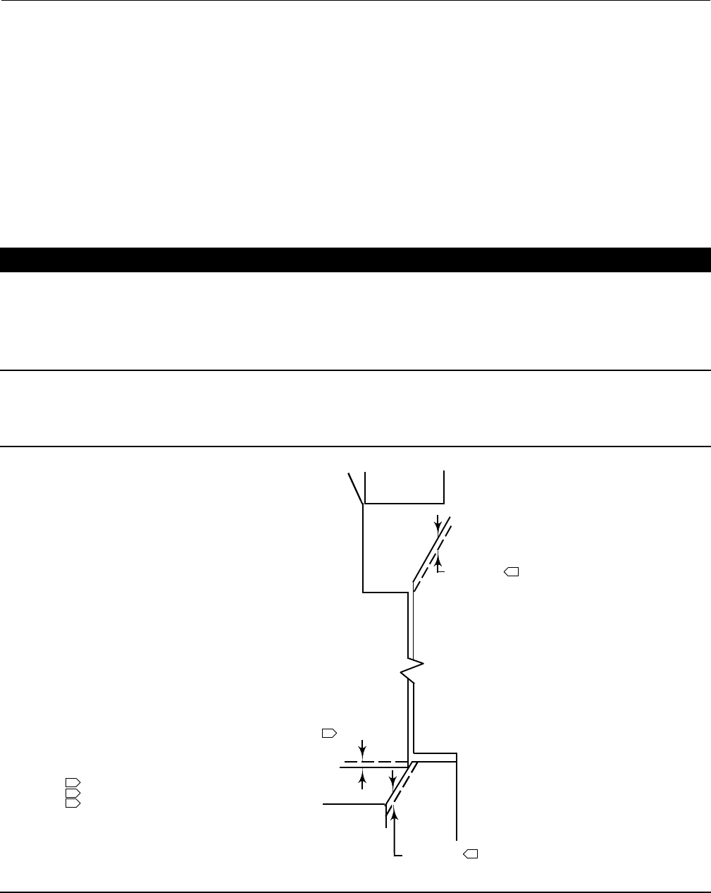
Figure 15. Example of Machining the Lower (Valve Plug to Seat Ring) and Upper (C-seal Plug Seal to Cage) Seating
Surfaces
UPPER SEATING SURFACE
0.508 (0.020)(4)
0.254 (0.010)(4)
0.254 (0.010)(4)
C-seal
RETAINER
MACHINING OF THE UPPER
SEATING SURFACE MUST
EQUAL THE TOTAL MACHINING OF
THE LOWER SEATING SURFACE
(PLUG PLUSSEAT RING). IF NOT,THE
RETAINER MAY STRIKE THE UPPER
SEATING SURFACE BEFORE THE
VALVE PLUG PROPERLY SEATS ON
THE LOWER SEATING SURFACE.
LOWER SEATING SURFACE
REMOVAL OF 0.254 mm (0.010 inch) FROM THE VALVE PLUG
PLUS REMOVAL OF 0.254 mm (0.010 inch) FROM THE SEAT RING
REMOVAL OF 0.508 mm (0.020 inch) FROM THE
UPPER SEATING SURFACE IN THE CAGE
4. THESE VALUES ARE FOR EXAMPLE ONLY. REMOVE ONLY THE
MINIMUM AMOUNT OF MATERIAL REQUIRED TO REFURBISH THE SEATS.
SEAT
RING
PLUG
CAGE
A6781 / IL
1
3
2
1
2
3
NOTE:
MUST EQUAL
mm (inch)

Instruction Manual
D100394X012
EH (1-1/2x1 through 8x6)
December 2014
29
Parts Ordering
Each body-bonnet assembly is assigned a serial number, which can be found on the valve body. This same number also
appears on the actuator nameplate when the valve body is shipped from the factory as part of a control valve
assembly. Refer to the number when contacting your Emerson Process Management sales office for technical
assistance or when ordering replacement parts.
When ordering replacement parts, also be sure to include the 11-character part number for each part required from
the following parts list.
WARNING
Use only genuine Fisher replacement parts. Components that are not supplied by Emerson Process Management should
not, under any circumstances, be used in any Fisher valve, because they may void your warranty, might adversely affect the
performance of the valve, and could cause personal injury and property damage.
Parts Kits
Standard Packing Repair Kits (Non Live-Loaded)
Stem Diameter, mm (Inches)
Yoke Boss Diameter, mm (Inches)
12.7 (1/2)
71 (2-13/16)
19.1 (3/4)
90 (3-9/16)
25.4 (1)
127 (5)
31.8 (1-1/4)
127 (5, 5H)
PTFE (Contains keys 6, 8, 10, 11, and 12) RPACKX00022 RPACKX00032 RPACKX00342 RPACKX00352
Double PTFE (Contains keys 6, 8, 11, and 12) RPACKX00052 RPACKX00062 RPACKX00362 RPACKX00372
PTFE/Composition (Contains keys 7, 8, 11, and 12) RPACKX00082 RPACKX00092 --- ---
Single Graphite Ribbon/Filament (Contains keys 7 [ribbon ring],
7 [filament ring], 8, and 11) RPACKX00112 RPACKX00122 --- ---
Single Graphite Ribbon/Filament (Contains keys 7 [ribbon ring],
7 [filament ring], and 11) --- --- RPACKX00532 RPACKX00542
Single Graphite Ribbon/Filament (Contains keys 7 [ribbon ring],
7 [filament ring]) RPACKX00142 RPACKX00152 --- ---
Double Graphite Ribbon/Filament (Contains keys 7 [ribbon ring],
7 [filament ring], 8, and 11) RPACKX00172 RPACKX00182 --- ---
Repair Kits (ENVIRO-SEAL)
Stem Diameter, mm (Inches)
Yoke Boss Diameter, mm (Inches)
12.7 (1/2)
71 (2-13/16)
19.1 (3/4)
90 (3-9/16)
25.4 (1)
127 (5)
31.8 (1-1/4)
127 (5, 5H)
Double PTFE (Contains keys 214, 215, 218) RPACKX00202 RPACKX00212 RPACKX00222 RPACKX00232
Single Graphite ULF (Contains keys 207, 208, 209, 210, 214) RPACKX00602 RPACKX00612 RPACKX00622 RPACKX00632
Duplex (Contains keys 207, 209, 214, 215) RPACKX00302 RPACKX00312 RPACKX00322 RPACKX00332
Retrofit Kits (ENVIRO-SEAL)
Stem Diameter, mm (Inches)
Yoke Boss Diameter, mm (Inches)
12.7 (1/2)
71 (2-13/16)
19.1 (3/4)
90 (3-9/16)
25.4 (1)
127 (5)
31.8 (1-1/4)
127 (5, 5H)
Double PTFE (Contains keys 200, 201, 211, 212,
214, 215, 216, 217, 218, tag, cable tie) RPACKXRT022 RPACKXRT032 RPACKXRT042 RPACKXRT052
Single Graphite ULF (Contains keys 200, 201, 207, 208, 209,
210, 211, 212, 214, 217, tag, cable tie) RPACKXRT272 RPACKXRT282 RPACKXRT292 RPACKXRT302
Duplex (Contains keys 200, 201, 207, 209, 211, 212, 214, 215,
216, 217, tag, cable tie) RPACKXRT222 RPACKXRT232 RPACKXRT242 RPACKXRT252

Instruction Manual
D100394X012
EH (1-1/2x1 through 8x6)
December 2014
30
Parts List
Note
Part numbers are shown for recommended spares only. For part
numbers not shown, contact your Emerson Process Management sales
office.
Bonnet Assembly (figure 16)
Key Description Part Number
1 Bonnet
If you need a bonnet as a replacement part,
order by valve size and stem diameter,
serial number, and desired material.
2 Baffle, for use with extension
bonnet only See following table
3 Packing Flange
4 Packing Flange Stud (2 req'd)
5 Packing Flange Nut (2 req'd)
6* Packing Set or Arrangement See following table
7* Packing Ring, low chloride graphite See following table
8 Packing Spring, 316 stainless steel See following table
8 Lantern Ring, 316 stainless steel See following table
10 Special Washer, 316 stainless steel See following table
11* Packing Box Ring, 316 stainless steel See following table
12* Upper Wiper, felt See table following
13 Packing Follower, 316 stainless steel See table following
14 Pipe Plug
14 Lubricator
14 Lubricator/Isolating Valve
15 Yoke Locknut
25 ActuatorMountingStud(8req'd)
26 Hex Nut (8 req'd)
35 Retaining Ring, for use with extension bonnet only
Valve Body (figures 17-21)
1 Valve Body, order by valve size, serial
number, and desired material
2* Cage See following table
3* Valve Plug See following table
4* Valve Plug Stem See following table
5* Pin See following table
6* Seat Ring See following table
7* Seat Ring Retainer See following table
Key Description Part Number
8* Piston Ring or Seal Ring See following table
9* Backup Ring See following table
10* Retaining Ring See following table
10* Retaining Ring (for EHT valve
body only) See following table
11* Cage Gasket (2 req'd) See following table
12* Seat Ring O-Ring or Gasket See following table
13 Bonnet Stud (8 req'd)
14 Hex Nut (8 req'd)
15 Flow Arrow
16 Drive Screw (4 req'd)
24 Anti-seize Lubricant
25 Seat Ring Retainer Tool (see figure 9)
416 stainless steel
CL2500 valve body rating
NPS 1, 1-1.2x1, & 2x1 valves 26A5469X012
NPS 2 & 3x2 valves 26A5495X012
NPS 3 & 4x3 valves 26A5496X012
NPS 4 & 6x4 valves 26A5497X012
NPS 6 & 8x6 valves 26A5498X012
26* O-Ring (for valve with Cavitrol III
trim only), ethylene/propylene See following table
27 Nameplate
28 Nameplate Wire
29 Bonnet Washer
29 Flat Washer (8 req'd)
30* Piston Ring (for EHT with Level D
Whisper Trim III cage only) See following table
33 Belleville Washer, N07718 (8 req'd)
63* Anti-Extrusion Ring See following table
C-seal Trim (figure 10)
2* Cage see following table
3* Valve Plug/Retainer see following table
4* Valve Plug Stem, S20910 see following table
6* Seat Ring see following table
8* Piston Ring, graphite (2 req'd) see following table
64* C-seal, N07718 see following table
TSO Trim (figure 7)
2* Cage See following table
4* Seat Ring See following table
5* Plug/Stem Assembly See following table
8* Seal Ring See following table
63* Anti-Extrusion Ring See following table
9* Back Up Ring See following table
10* Retaining Ring See following table
*Recommended spare parts
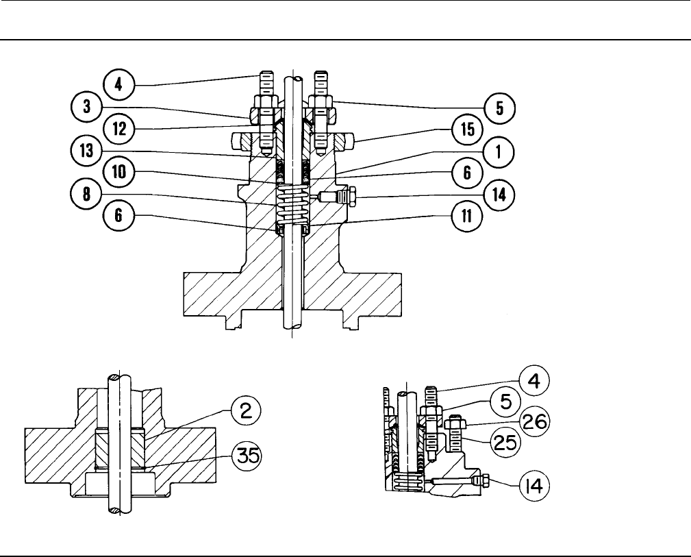
Instruction Manual
D100394X012
EH (1-1/2x1 through 8x6)
December 2014
31
Figure 16. Fisher EH Bonnet Assembly
71 mm (2-3/16 INCH) YOKE BOSS BONNET
WITH SINGLE ARRANGEMENT PTFE PACKING
56A5372-E
A2699-2
DETAIL OF BAFFLE AND RETAINING RING
USED IN EXTENSION BONNET
DETAIL OF 127 mm (5-INCH) YOKE BOSS ACTUATOR BOLTING
(OPTIONALFORNPS3,4,&6EHSERIESVALVEBODIES)
18A8557-A
35A3976-A
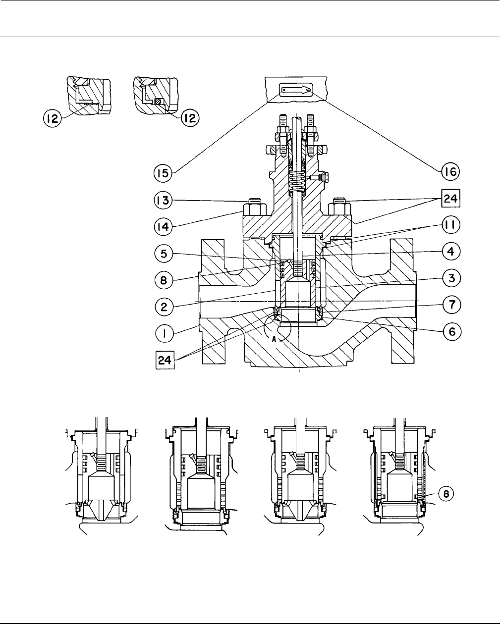
Instruction Manual
D100394X012
EH (1-1/2x1 through 8x6)
December 2014
32
Figure 17. Fisher EHD Valve
FLOW DIRECTION FOR ALL TRIMS EXCEPT WITH A WHISPER
TRIM III CAGE OR A VALVE PLUG WITH DIVERTER CONE
VIEW A
jAPPLY LUB
56A5372-F
GASKETED SEAT RING
CONSTRUCTION
O-RING SEAT RING
CONSTRUCTION
EHDBODYWITHSTANDARDTRIM
DETAIL OF PLUG WITH
DIVERTER CONE, FOR
NPS 6 BODY ONLY
DETAIL OF WHISPER
TRIM III CAGE FOR
NPS 3 THROUGH 4 BODIES
DETAILOFLEVELA,B,OR
C WHISPER TRIM III CAGE
AND VALVE PLUG WITH
DIVERTER CONE, FOR
NPS 6 BODY ONLY
DETAIL OF LEVEL D
WHISPER TRIM III CAGE
AND VALVE PLUG, FOR
NPS 6 BODY ONLY
ALTERNATE CONFIGURATIONS
REFERENCE STANDARD TRIM KEY NUMBERS EXCEPT AS SHOWN
59A9166-A 57A2887-A 59A9188-A 59A9190-A
PARTS NOT SHOWN: KEY 29 FLAT WASHER
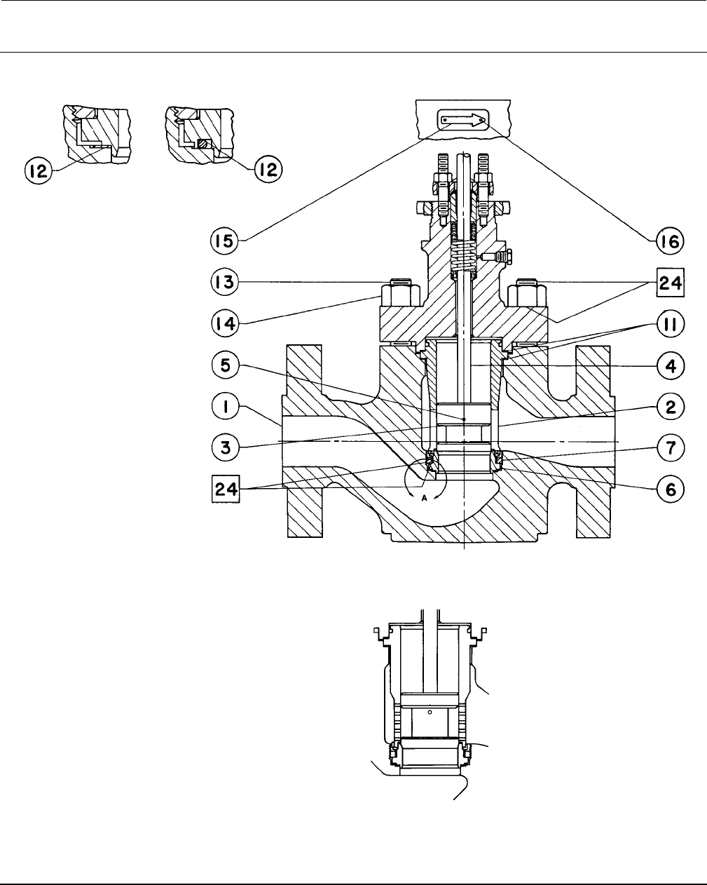
Instruction Manual
D100394X012
EH (1-1/2x1 through 8x6)
December 2014
33
Figure 18. Fisher EHS Valve
FLOW DIRECTION FOR ALL TRIMS EXCEPT THOSE WITH A CAVITROL III CAGE
VIEW A
jAPPLY LUB
56A5494-E
GASKETED SEAT RING
CONSTRUCTION
O-RING SEAT RING
CONSTRUCTION
EHS BODY WITH STANDARD TRIM
DETAIL OF WHISPER TRIM III CAGE,
FOR NPS 2 THROUGH 6 BODIES
ALTERNATE CONFIGURATIONS
REFERENCE STANDARD TRIM KEY NUMBERS EXCEPT AS SHOWN
57A2891-B
PARTS NOT SHOWN: KEY 29 FLAT WASHER

Instruction Manual
D100394X012
EH (1-1/2x1 through 8x6)
December 2014
34
Figure 19. Belleville Washer Body-to-Bonnet Bolting
GE60624-C
SHOWN IN
UNCOMPRESSED
“FREE” POSITION
BONNET
BONNET
SHOWN IN
UNCOMPRESSED
“FREE” POSITION
NPS 1-1/2 THROUGH NPS 4 ALL ASME CLASSES
NPS 6 ALL ASME CLASSES EXCEPT CL2500 NPS 6 CL2500
NPS 8 AND LARGER ALL ASME CLASSES
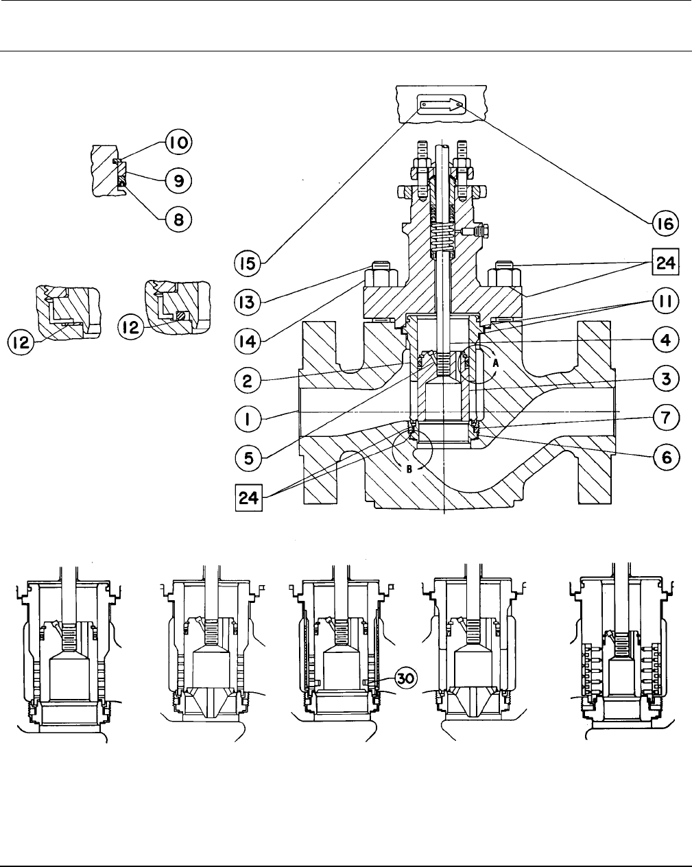
Instruction Manual
D100394X012
EH (1-1/2x1 through 8x6)
December 2014
35
Figure 20. Fisher EHT Valve FLOW DIRECTION FOR ALL TRIMS EXCEPT WITH A WHISPER
TRIM III CAGE OR A VALVE PLUG WITH DIVERTER CONE
VIEW B
jAPPLY LUB
56A5487-E
GASKETED SEAT RING
CONSTRUCTION
O-RING SEAT RING
CONSTRUCTION
EHT BODY WITH STANDARD TRIM
DETAIL OF WHISPER
TRIM III CAGE FOR
NPS 3 THROUGH 4 BODIES
DETAILOFLEVELA,B,ORC
WHISPER TRIM III CAGE AND
VALVE PLUG WITH DIVERTER
CONE, FOR NPS 6
BODY ONLY
DETAIL OF LEVEL D
WHISPER TRIM III CAGE
AND VALVE PLUG, FOR NPS
6BODYONLY
DETAIL OF VALVE PLUG
WITH DIVERTER CONE, FOR
NPS 6 BODY ONLY
ALTERNATE CONFIGURATIONS
REFERENCE STANDARD TRIM KEY NUMBERS EXCEPT AS SHOWN
57A2889-A
59A9192-A 59A9194-A 59A9168-A
VIEW A
57A2883-B
DETAIL OF 3-STAGE
CAVITROL III CAGE, FOR
ALL BODIES EXCEPT NPS 1
AND CL2500 NPS 2
BODIES (2-STAGE CAGE
IS AVAILABLE FOR NPS 3
THROUGH 6 BODIES)
PARTS NOT SHOWN: KEY 29 FLAT WASHER
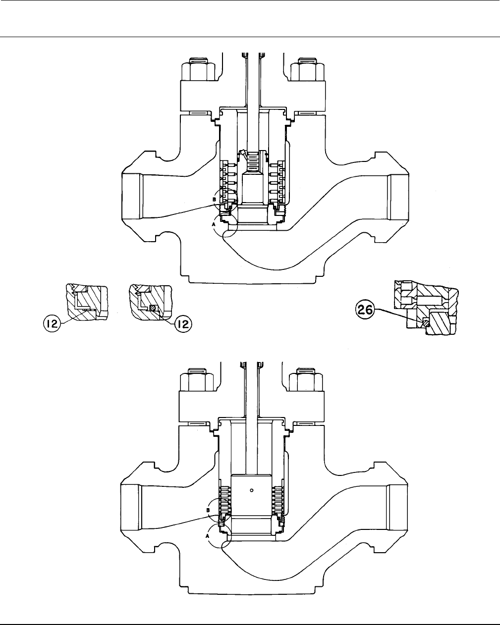
Instruction Manual
D100394X012
EH (1-1/2x1 through 8x6)
December 2014
36
Figure 21. Typical Cavitrol III Constructions
VIEW A
57A2883-B
GASKETED SEAT RING
CONSTRUCTION O-RING SEAT RING
CONSTRUCTION
DETAIL OF EHT BODY WITH 3-STAGE
CAVITROL III CAGE
DETAIL OF EHS BODY WITH 2-STAGE CAVITROL III CAGE
57A2881-B
O-RING SEAL BETWEEN
CAGE AND SEAT RING
VIEW B

Instruction Manual
D100394X012
EH (1-1/2x1 through 8x6)
December 2014
37
Keys 6*, 7*, and 12* Soft Packing Parts
PACKING
ARRANGEMENT
KEY
NUMBER
PACKING PART
DESCRIPTION
VALVE STEM CONNECTION
12.7 mm (1/2 Inch) 19.1 mm (3/4 Inch) 25.4 mm (1-Inch) 31.8 mm (1-1/4 Inch)
PTFE V-Ring
Packing
6Packing set, PTFE
(1 req'd for single,
2 req'd for double)(1)
1R290201012 1R290401012 1R290601012 1R290801012
12 Upper Wiper 1J872706332 1J872806332 1J872906332 1J873006332
Low chloride
graphite ribbon
and filament,
single
6Packing arrangement
(includes key 7)
13A9775X012 13A9776X012 14A2340X012 14A3412X012
7
7
Graphite Ribbon Ring
(2 req'd)
Graphite Filament Ring
[2 required for 1/2 inch
(12.7 mm) stem;
3 required for all others]
1V3802X0022
1E3190X0222
1V2396X0022
1E3191X0282
1U6768X0022
1D7518X0132
1V5666X0022
1D7520X0162
Low chloride
graphite ribbon
and filament,
double
6Packing arrangement
(includes key 7)
14A1849X012 14A1780X012 14A3413X012 14A3414X012
7
7
Graphite Ribbon Ring
(3 req'd)
Graphite Filament Ring
[4 required for 1/2 inch
(12.7 mm) stem;
5req'dforallothers]
1V3802X0022
1E3190X0222
1V2396X0022
1E3191X0282
1U6768X0022
1D7518X0132
1V5666X0022
1D7520X0162
PTFE/
composition,
double
6Packing arrangement
(includes key 7)
12A7815X012 12A8173X012 12A8150X012 12A8163X012
7Packing Ring
[10 required for 1/2 inch
(12.7 mm) stem;
8 required for all others]
1E319001042 1E319101042 1D7518X0012 1D7520X0012
12 Upper Wiper 1J872706332 1J872806332 1J872906332 1J873006332
1. Key 6 for double construction contains one extra lower wiper. Discard upon assembly.
*Recommended spare parts

Instruction Manual
D100394X012
EH (1-1/2x1 through 8x6)
December 2014
38
Keys 8, 10, 11* and 13 Metal Packing Parts
PACKING
TYPE
KEY
NUMBER DESCRIPTION
QUANTITY REQUIRED VALVE STEM
CONNECTION
MATERIAL
Single
Packing
Double
Packing
316
Stainless Steel
mm Inches
PTFE V-Ring
8Packing Spring
1
1
1
1
---
---
---
---
12.7
19.1
25.4
31.8
1/2
3/4
1
1-1/4
1F125537012
1F125637012
1D582937012
1D387437012
8Lantern Ring
---
---
---
---
2
1
1
1
12.7
19.1
25.4
31.8
1/2
3/4
1
1-1/4
1J962335072
0N028435072
0U099735072
0W087135072
10 Special Washer
1
1
1
1
---
---
---
---
12.7
19.1
25.4
31.8
1/2
3/4
1
1-1/4
1F125136042
1F125036042
1H982236042
1H995936042
11 Packing Box Ring
1
1
1
1
1
1
1
1
12.7
19.1
25.4
31.8
1/2
3/4
1
1-1/4
1J873235072
1J873335072
1J873435012
1J873535012
13 Packing Follower
1
1
1
1
1
1
1
1
12.7
19.1
25.4
31.8
1/2
3/4
1
1-1/4
1E944335072
1E944735072
1H982335072
1H998435072
Low Chloride Graphite
Ribbon/Filament
8Lantern Ring
3
2
2
2
2
1
1
1
12.7
19.1
25.4
31.8
1/2
3/4
1
1-1/4
1J962335072
0N028435072
0U099735072
0W087135072
11 Packing Box Ring
1
1
1
1
1
1
1
1
12.7
19.1
25.4
31.8
1/2
3/4
1
1-1/4
1J873235072
1J873335072
1J873435012
1J873535012
13 Packing Follower
1
1
1
1
1
1
1
1
12.7
19.1
25.4
31.8
1/2
3/4
1
1-1/4
1E944335072
1E944735072
1H982335072
1H998435072
PTFE/Composition
8Lantern Ring
---
---
---
---
1
1
1
1
12.7
19.1
25.4
31.8
1/2
3/4
1
1-1/4
1J962335072
0N028435072
0U099735072
0W087135072
11 Packing Box Ring
---
---
---
---
1
1
1
1
12.7
19.1
25.4
31.8
1/2
3/4
1
1-1/4
1J873235072
1J873335072
1J873435012
1J873535012
13 Packing Follower
---
---
---
---
1
1
1
1
12.7
19.1
25.4
31.8
1/2
3/4
1
1-1/4
1E944335072
1E944735072
1H982335072
1H998435072
*Recommended spare parts

Instruction Manual
D100394X012
EH (1-1/2x1 through 8x6)
December 2014
39
Key 2* Cage For Valve Bodies Without Whisper Trim III Cage or Cavitrol III Trim
VALVE
BODY
RATING
VALVE
SIZE,
NPS
CAGE
DESCRIPTION
TRAVEL
MATERIAL
S17400 (17-4PH
Stainless Steel)
with H1075
Heat Treatment
S42200
(422 Stainless
Steel) Ion
Nitride
S31600
(316 Stainless
Steel)
Electrolized
S31600 (316 Stainless
Steel) Electroless
Nickel Coated for
NACE MR0175-2002(1)
mm Inches
CL2500
1-1/2 x 1,
2x1 Quick opening 22 0.875 39A8550X042 39A8550X032 30B2539X012 31B4270X012
3x2 Equal percentage
Linear
22, 29
29
0.875, 1.125
1.125
39A9228X012
39A9229X012
39A9228X042
39A9229X042
39A9230X042
39A9231X022
30B7103X012
31B4272X012
3, 4 x 3 Equal percentage
Linear
29, 38
29, 38
1.125, 1.5
1.125, 1.5
39A9068X012
39A9069X012
39A9068X032
39A9069X032
39A9070X022
39A9071X022
30B9995X012
31B4273X012
4, 6 x 4 Equal percentage
Linear
38, 51
38, 51
1.5, 2
1.5, 2
42B3564X012
42B3561X012
42B3564X022
42B3561X022
42B3565X012
42B3562X012
42B3566X012
42B3563X012
6, 8 x 6(2) Equal percentage
Linear
51, 76
51, 76
2, 3
2, 3
42B3576X012
42B3573X012
42B3576X022
42B3573X022
42B3577X012
42B3574X012
42B3578X012
42B3575X012
1. These materials are listed in NACE Standard MR0175-2002 as being acceptable for direct exposure to sour environment when used under conditions stated in that standard.
2. Flow down only with EHD and EHT style of valve plug. For flow up with balanced valve plug, contact factory.
Key2*CageorCageandBaffleAssemblyforValveBodywithWhisperTrimIIICage
VALVE
BODY
RATING
VALVE
SIZE,
NPS
CAGE
DESCRIPTION
PORT
DIAMETER TRAVEL
MATERIAL
S17400 (17-4PH
Stainless Steel)
with H1075
Heat Treatment
S17400 (17-4PH
Stainless Steel)
with H1150
Heat Treatment
For NACE
MR0175-2002
S42200 (422
Stainless
Steel) Ion
Nitride
mm Inches mm Inches
CL2500
3x2 Level A1 38.1 1.5 38 1.5 37A2741X012 37A2741X022 37A2741X032
3, 4 x 3 Level A1
Level B1
58.7
58.7
2.3125
2.3125
38
38
1.5
1.5
37A2766X012
37A2768X012
37A2766X022
37A2768X022
37A2766X032
37A2768X032
4, 6 x 4
Level A1
Level B1
Level B3
73.0
73.0
73.0
2.875
2.875
2.875
51
51
51
2
2
2
37A2774X012
37A2776X012
37A2778X012
37A2774X022
37A2776X022
37A2778X022
31B4630X012
31B4631X012
31B4632X012
6, 8 x 6
Level A1
Level B3
Level C3
Level D3(1)
111.1
111.1
111.1
111.1
4.375
4.375
4.375
4.375
76
76
76
76
3
3
3
3
30B1113X022
30B1115X022
30B1117X022
30B1182X032
30B1113X012
30B1115X012
30B1117X012
30B1182X012
30B1113X032
30B1115X032
30B1117X032
30B1182X022
1. Cage and baffle assembly.
Key 2* Cage Assembly for Fisher EHS or EHT Valve Body with Cavitrol III Trim
VALVE
BODY
RATING
VALVE
SIZE,
NPS
CAGE ASSEMBLY
DESCRIPTION
PORT DIAMETER TRAVEL MATERIAL
S17400 (17-4PH Stainless
Steel) with H1075
Heat Treatment
mm Inches mm Inches
CL2500
1-1/2 x 1, 2 x 1 Full 2-stage 15.9 0.625 32 1.25 37A2283X022
3x2 Full 2-stage
Full 3-stage
31.8
15.9
1.25
0.625
51
51
2
2
37A2309X012
37A2319X012
3, 4 x 3 Full 2-stage
Full 3-stage
47.6
33.3
1.875
1.3125
64
64
2.5
2.5
37A4328X012
37A4335X012
4, 6 x 4 Full 2-stage
Full 3-stage
73.0
58.7
2.875
2.3125
70
70
2.75
2.75
37A4366X012
37A4376X012
6, 8 x 6 Full 2-stage
Full 3-stage
111.1
111.1
4.375
4.375
95
95
3.75
3.75
37A4420X012
37A4432X012
*Recommended spare parts

Instruction Manual
D100394X012
EH (1-1/2x1 through 8x6)
December 2014
40
C-seal Parts for Fisher EHD Valve (Keys 2*, 3*, 6*, 64*, 8*, and 4*)
VALVE
SIZE
PORT
DIA TRAVEL TRIM
STEM
DIAMETER CHARACTER-
ISTIC
CAGE PLUG/
RETAINER SEAT RING C-seal PISTON RING
(2 req'd) STEM
NPS Inch Inch mm Inch Key 2 Key 3 Key 6 Key 64 Key 8 Key 4
4
CL2500 2.875 254 19.1 3/4 Equal % 44B9814X012 24B9002X012 34B9000X012 24B3621X012 14B3620X012 17A2167X202
Key 3* Valve Plug for Fisher EHS Valve Body with Micro-Form Plug
VALVE
BODY
RATING
VALVE
SIZE,
NPS
VALVE
STEM
CONNECTION
PORT
DIAMETER
MATERIAL
S41600
(416 Stainless
Steel)
S31600 (316 Stainless Steel) With
CoCr-A (Alloy 6) Seat, Guide, and Contour
Diameter
A(1)
Diameter
B(1)
Diameter
C(1)
Diameter
D(1)
mm Inches mm Inches
CL2500
1-1/2 x 1
12.7
12.7
12.7
1/2
1/2
1/2
6.4
12.7
19.1
0.25
0.5
0.75
16A5335X012
16A5336X012
16A5337X012
---
---
---
16A5413X012
16A5414X012
16A5415X012
16A5413X052
16A5414X112
16A5415X142
---
---
---
3x2
12.7
19.1
25.4
1/2
3/4
1
25.4
25.4
25.4
1
1
1
16A5403X012
16A5338X012
16A5339X022
16A5416X012
16A5417X012
16A5418X012
---
---
---
16A5416X042
16A5417X092
16A5418X062
---
---
---
1. See table 12 for plug diameters vs operating temperatures.
Table 12. Valve Plug Diameters and Operating Temperatures
CAGE MATERIAL STEM MATERIAL OPERATING TEMPERATURE RANGE DIAMETER
CODE
VALVE BODY
DESIGN
_C_F
S31600 (316 Stainless
Steel) Electrolized
S31600 -198 to +427 -325 to +800 AEHD, EHS
S31600 Electrolized -29 to +593 -20 to +1100
S31600 ENC (NACE) S20910 -40 to +232 -40 to +450 AEHD, EHS
S17400 (17-4PH Stain-
less Steel) H1150 (NACE) S20910 -40 to +232 -40 to +450 AEHS
S17400 H1150 (NACE) S20910 -40 to +232 -40 to +450 BEHD
S31600 Electrolized S31600 -198 to +427 -325 to +800 BEHS
S31600 Electrolized -29 to +593 -20 to +1100
S31600 ENC (NACE) S20910 -40 to +232 -40 to +450 BEHS
S42200 (422 Stainless
Steel) Ion Nitride S31600 Electrolized 427 to 566 +800 to 1050 CEHD, EHS
S42200 Ion Nitride S31600 Electrolized 427 to 510 +800 to 950 DEHD, EHS
S31600 Electrolized S31600 -198 to +427 -325 to +800 DEHD, EHS
S31600 Electrolized -29 to +593 -20 to +1100
S31600 ENC (NACE) S20910 -40 to +232 -40 to +450 DEHD, EHS
S42200 Ion Nitride S31600 Electrolized 427 to 510 +800 to 950 EEHD, EHS
S42200 Ion Nitride S31600 Electrolized 510 to 566 +950 to 1050 FEHD, EHS
S31600 Electrolized S31600 -198 to +427 -325 to +800 KEHD
S31600 Electrolized -29 to +593 -20 to +1100
S31600 ENC (NACE) S20910 -40 to +232 -40 to +450 KEHD
*Recommended spare parts

Instruction Manual
D100394X012
EH (1-1/2x1 through 8x6)
December 2014
41
Key 3* Valve Plug for 1-1/2 x 1 and 2 x 1 Fisher EHS Valve Body with Micro-Flute Valve Plug
VALVE
BODY
RATING
PLUG
STYLE
PORT
DIAMETER
MATERIAL
S31600 (316 Stainless Steel)
With CoCr-A (Alloy 6) Seat, Guide, and Tip S44004
(440C Stainless Steel)
with Heat Treatment
mm Inches Diameter
B(1)
Diameter
C(1)
CL2500
1Flute
2Flutes
3Flutes
3Flutes
3Flutes
6.4
6.4
6.4
9.5
12.7
0.25
0.25
0.25
0.375
0.5
18A1654X012
18A1655X012
18A1656X012
18A1658X012
18A1660X012
18A1654X042
18A1655X042
18A1656X042
18A1658X052
18A1660X052
18A1651X012
18A1652X012
18A1653X012
18A1657X012
18A1659X012
1. See table 12 for plug diameters vs operating temperatures.
Key 3* Valve Plug or Plug/Diverter for an NPS 2 through 4 CL2500 Valve Without Micro-Form, Micro-Flute, or
Cavitrol III Trim. Also for Use With an NPS 2 or 3 Valve With a Whisper Trim III Cage
VALVE
SIZE,
NPS
VALVE
BODY
DESIGN
VALVE
STEM
CONNEC-
TION
PORT
DIAMETER
MATERIAL
S31600
(316 Stainless
Steel) With
CoCr-A (Alloy 6)
Seat and Guide
S31600 (316 Stainless
Steel) With CoCr-A
(Alloy 6) Seat and Guide S41600
(416 Stainless
Steel)
Diameter
A(1)
Diameter
C(1)
Diameter
D(1)
Diameter
E(1)
mm Inches mm Inches
3x2
EHD 12.7 1/2 38.1 1.5 --- 36A5450X012 36A5450X072 --- --- 36A5373X012
EHT 12.7 1/2 38.1 1.5 36A5451X012 --- --- --- --- 36A5374X012
EHS
12.7
19.1
25.4
1/2
3/4
1
38.1
38.1
38.1
1.5
1.5
1.5
---
---
---
16A5452X012
16A5453X012
16A5454X012
16A5452X042
16A5453X062
16A5454X052
---
---
---
---
---
---
16A5375X012
16A5376X012
16A5377X012
3, 4 x 3
EHD
12.7
19.1
25.4
1/2
3/4
1
58.7
58.7
58.7
2.3125
2.3125
2.3125
---
---
---
36A5455X012
36A5456X012
36A5457X012
---
---
---
36A5455X042
36A5456X072
36A5457X062
---
---
---
36A5378X012
36A5379X012
36A5380X012
EHT
12.7
19.1
25.4
1/2
3/4
1
58.7
58.7
58.7
2.3125
2.3125
2.3125
36A5458X012
36A5459X012
36A5460X012
---
---
---
---
---
---
---
---
---
---
---
---
36A5381X012
36A5382X012
36A5383X012
EHS
12.7
19.1
25.4
1/2
3/4
1
58.7
58.7
58.7
2.3125
2.3125
2.3125
---
---
---
16A5461X012
16A5462X012
16A5463X012
---
---
---
36A5461X042
36A5462X042
36A5463X052
---
---
---
16A5384X012
16A5385X012
16A5386X012
4, 6 x 4
EHD 19.1
25.4
3/4
1
73.0
73.0
2.875
2.875
---
---
36A5464X012
36A5465X012
---
---
---
---
36A5464X072
36A5465X052
36A5387X012
36A5388X012
EHT 19.1
25.4
3/4
1
73.0
73.0
2.875
2.875
36A5466X012
36A5467X012
---
---
---
---
---
---
---
---
36A5389X012
36A5390X012
EHS 19.1
25.4
3/4
1
73.0
73.0
2.875
2.875
---
---
16A5433X012
16A5434X012
---
---
16A5433X042
16A5434X062
---
---
16A5354X042
16A5355X042
1. See table 12 for plug diameters vs operating temperatures.
*Recommended spare parts
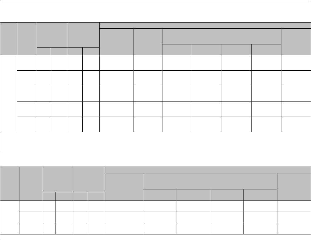
Instruction Manual
D100394X012
EH (1-1/2x1 through 8x6)
December 2014
42
Key 3* Valve Plug or Plug/Diverter for an NPS 6 CL2500 Valve Without Micro-Form, Micro-Flute, or Cavitrol III Trim
VALVE
SIZE,
NPS
VALVE
BODY
DESIGN
VALVE
STEM
CONNEC-
TION
PORT
DIAMETER
MATERIAL
S31600
(316 Stainless
Steel) With
CoCr-A (Alloy 6)
Seat and Guide
S17400
(17-4PH
Stainless
Steel)
H900
S31600 (316 Stainless
Steel) With CoCr-A
(Alloy 6) Seat and Guide S41600
(416 Stainless
Steel)
Diameter
A(1)
Diameter
D(1)(2)
Diameter
E(1)(3)
Diameter
K(1)
mm Inches mm Inches
6, 8 x 6
EHD
19.1
25.4
31.8
3/4
1
1-1/4
111.1
111.1
111.1
4.375
4.375
4.375
---
---
---
---
---
---
36A5470X012
36A5471X012
36A5472X012
36A5470X062
36A5471X062
36A5472X062
36A5470X052
36A5471X072
36A5472X052
---
---
---
36A5393X012
36A5394X012
36A5395X012
EHD with
diverter(
4)
31.8 1-1/4 111.1 4.375 --- 31B4887X012 --- 39A9118X042 39A9118X052 39A9118X162 ---
EHT
19.1
25.4
31.8
3/4
1
1-1/4
111.1
111.1
111.1
4.375
4.375
4.375
36A5473X012
36A5474X012
36A5475X012
---
---
---
---
---
---
---
---
---
---
---
---
---
---
---
36A5396X012
36A5397X012
36A5398X012
EHT with
diverter(
4)
31.8 1-1/4 111.1 4.375 39A9119X072 31B4889X012 --- --- --- --- ---
EHS
19.1
25.4
31.8
3/4
1
1-1/4
111.1
111.1
111.1
4.375
4.375
4.375
---
---
---
---
---
---
36A5476X012
36A5477X012
36A5478X012
36A5476X042
36A5477X042
36A5478X042
36A5476X052
36A5477X052
36A5478X052
---
---
---
16A5399X012
16A5400X012
16A5401X012
1. See table 12 for plug diameters vs operating temperatures.
2. Temperature limit due to diametrical expansion 427_to 510_C (800_to 950_F).
3. Temperature limit due to diametrical expansion 510_to 566_C (950_to 1050_F).
4. Flow up only.
Key3*ValvePlugforNPS4and6x4ValveWithWhisperTrimIIICage
VALVE
BODY
RATING
VALVE
BODY
DESIGN
VALVE
STEM
CONNEC-
TION
PORT
DIAMETER
MATERIAL
S41600
(416 Stainless
Steel)
S31600 (316 Stainless
Steel) With CoCr-A
(Alloy 6) Seat and Guide
S31600
with CoCr-A
Seat and
Guide
Diameter
A(1)
Diameter
B(1)
Diameter
D(1)
Diameter
E(1)
mm Inches mm Inches
CL2500
EHD 19.1
25.4
3/4
1
73.0
73.0
2.875
2.875
36A5387X012
36A5388X042
36A5464X012
36A5465X012
---
---
---
---
36A5464X072
36A5465X052
---
---
EHT 19.1
25.4
3/4
1
73.0
73.0
2.875
2.875
36A5389X012
36A5390X012
---
---
---
---
---
---
---
---
36A5466X012
36A5467X012
EHS 19.1
25.4
3/4
1
73.0
73.0
2.875
2.875
16A5354X012
16A5355X012
36A5433X012
36A5434X012
---
---
36A5433X042
36A5434X062
---
---
---
---
1. See table 12 for plug diameters vs operating temperatures.
*Recommended spare parts

Instruction Manual
D100394X012
EH (1-1/2x1 through 8x6)
December 2014
43
Key3*ValvePlugforNPS6and8x6ValvewithWhisperTrimIIICage
VALVE
BODY
DESIGN
MATERIAL
OPERATING
TEMPERATURE
RANGE
DIAMETER
CODE
STAMPED
ON TOP OF
VALVE PLUG
VALVE STEM
CONNECTION
VALVE BODY RATING AND CAGE LEVEL
CL2500
Level
A, B, or C Level D
_C_Fmm Inches
EHD
17-4PH stainless
steel with H900
heat treatment(1)
0 to 427 32 to 800 N.A.
25.4 131B4888X012 39A9100X012
31.8 1-1/4 31B4887X012 39A9102X012
316 stainless
steel with alloy
6 (CoCr-A) seat
and guide
-40 to 232 -40 to 450 A(2) 25.4 139A9116X012 39A9104X012
31.8 1-1/4 39A9118X012 39A9106X012
427 to 510 800 to 950 E(3) 25.4 139A9116X052 39A9104X052
31.8 1-1/4 39A9118X052 39A9106X052
510 to 566 950 to 1050 F(3) 25.4 139A9116X062 39A9104X062
31.8 1-1/4 39A9118X062 39A9106X062
-40 to 232 -40 to 450 K(2) 25.4 1--- ---
31.8 1-1/4 --- ---
EHT
17-4PH stainless
steel with H900
heat treatment(1)
0 to 427 32 to 800 N.A.
25.4 131B4890X012 39A9101X012
31.8 1-1/4 31B4889X012 39A9103X012
316 stainless
steel with alloy
6 (CoCr-A) seat
and guide
-40 to 232 -40 to 450 A(2) 25.4 139A9117X012 39A9105X012
31.8 1-1/4 39A9119X012 39A9107X012
-40 to 232 -40 to 450 D(2) 25.4 1--- ---
31.8 1-1/4 --- ---
1. 17-4PH H1075 cage.
2. 17-4PH H1150 cage for NACE MR0175-2002.
3. S42200 (422 stainless steel) ion nitride cage.
Key 3* Valve Plug and Stem Assembly for a CL2500 Valve with Cavitrol III Trim
VALVE
SIZE,
NPS
DESIGN STAGE ACTUATOR
GROUP
VALVE STEM
CONNECTION
PORT
DIAMETER
MATERIAL
S44004 (440C
Stainless Steel)
mm Inches mm Inches
1.5 x 1
&2x1 EHS 2 1 12.7
19.1
1/2
3/4
15.9
15.9
0.625
0.625
17A2286X012
17A2286X032
3x2
EHS 3 1 12.7
19.1
1/2
3/4
15.9
15.9
0.625
0.625
17A2323X012
17A2323X032
EHT 2 1 12.7
19.1
1/2
3/4
31.8
31.8
1.25
1.25
27A2312X012
27A2312X032
3&4x3 EHT
2
400
1
100
101
12.7
19.1
25.4
25.4
1/2
3/4
1
1
47.6
47.6
47.6
47.6
1.875
1.875
1.875
1.875
37A4320X032
37A4321X052
37A4321X062
37A4321X072
3
400
1
100
101
12.7
19.1
25.4
25.4
1/2
3/4
1
1
33.3
33.3
33.3
33.3
1.3125
1.3125
1.3125
1.3125
27A4339X012
27A4340X012
27A4340X032
27A4340X042
4&6x4 EHT
2
1
100
101
19.1
25.4
25.4
3/4
1
1
73
73
73
2.875
2.875
2.875
37A4358X032
37A4359X042
37A4359X052
3
1
100
101
19.1
25.4
25.4
3/4
1
1
58.7
58.7
58.7
2.3125
2.3125
2.3125
37A4380X022
37A4381X022
37A4381X032
6&8x6 EHT 2&3
401 & 403
402
19.1
19.1
3/4
3/4
111.1
111.1
4.375
4.375
37A4423X022
37A4423X032
404
405
406
407
25.4
25.4
25.4
25.4
1
1
1
1
111.1
111.1
111.1
111.1
4.375
4.375
4.375
4.375
37A4424X022
37A4424X032
37A4424X042
37A4424X052
404
405
406
407
31.8
31.8
31.8
31.8
1-1/4
1-1/4
1-1/4
1-1/4
111.1
111.1
111.1
111.1
4.375
4.375
4.375
4.375
37A4425X022
37A4425X032
37A4425X042
37A4425X052
*Recommended spare parts

Instruction Manual
D100394X012
EH (1-1/2x1 through 8x6)
December 2014
44
Key 4* Valve Plug Stem for CL2500 Valve without Whisper Trim III or Cavitrol III Trim
VALVE
SIZE,
NPS
ACTUATOR
GROUP
VALVE
STEM
CONNECTION
VALVE
STEM
TRAVEL DESCRIPTION
MATERIAL
S31600 (316
Stainless
Steel)
Electrolized
S31600
S20910 for
NACE
MR0175-2002
mm Inches mm Inches
1-1/2 x 1,
2x1 1
12.7 1/2
19.1 0.75
Micro-Form or Micro-
Flute with 6.4 mm
(0.25-inch) port
10A8840XB42 13A7368X062 10A8840XT82
19.1 0.75
Micro-Flute with
9.5 mm (0.375-inch) or
12.7 mm (0.5-inch) port
10A8840XB42 13A7368X062 10A8840XT82
19.1, 22 0.75,
0.875
Micro-Form with
12.7 mm (0.5-inch) or
19.1 mm (0.75 inch) port
10A8840XC52 13A7368X092 10A8840X022
19.1 3/4 19.1, 22 0.75,
0.875
Micro-Form with 12.7 mm
(0.5-inch) or 19.1 mm
(0.75-inch) port
16A4704X062 29A9091X012 16A4704X252
3x2
1
12.7 1/2 22.2, 28.6,
38.1
0.875,
1.125, 1.5
Micro-Form, EHS,
EHD, EHT 1K587435162 13A7368X112 1K5874X0062
19.1 3/4 22.2, 28.6,
38.1
0.875,
1.125, 1.5
Micro-Form, EHS 1U507135162 17A2167X082 1U5071X0042
100 25.4 1
22.2 0.875 Micro-Form, EHS 1K7891X0012 15A9264X182 1K7891X0242
28.6 1.125 Micro-Form, EHS 1N325635162 15A9264X162 1N3256X0052
38.1 1.5 Whisper Trim III, EHS 1P597335162 15A2964X152 11A3429XG82
101 25.4 122.2, 28.6,
38.1
0.875,
1.125, 1.5 Micro-Form, EHS 1P9972X0012 15A9264X122 1P9972X0032
3, 4 x 3
1
12.7 1/2 28.6,
38.1
1.125,
1.5
EHD, EHT
EHS
10A8840X762
1U218035162
13A7368X142
13A7368X132
10A8840XU52
1U2180X0012
19.1 3/4 28.6,
38.1
1.125,
1.5
EHD, EHT
EHS
1U507135162
1U928235162
17A2167X082
17A2167X022
1U5071X0042
1U9282X0192
100 25.4 1
28.6 1.125 EHD, EHT
EHS
1L877635162
1N4180X0012
15A9264X192
15A9264X242
1L8776X0032
1N4180X0072
38.1 1.5 EHD, EHT
EHS
1N325635162
1L3765X0012
15A9264X162
15A9264X232
1N3256X0052
1L3765X0072
101 25.4 128.6, 38.1 1.125, 1.5 EHD, EHT
EHS
1L2687X0012
1P597335162
15A9264X302
15A9264X152
1L2687X0152
11A3429XG82
4, 6 x 4
119.1 3/4 38.1, 50.8 1.5, 2 EHD, EHT
EHS
1U507135162
1U6674X0012
17A2167X082
17A2167X092
1U5071X0042
1U6674X0052
100 25.4 1
38.1 1.5 EHD, EHT
EHS
1K785135162
1L424935162
15A9264X212
15A9264X282
1K7851X0032
1L4249X0052
50.8 2EHD, EHT
EHS
1K7891X0012
1L2273X00A2
15A9264X182
15A9264X262
1K7891X0242
1L2273X0042
101 25.4 138.1, 50.8 1.5, 2 EHD, EHT
EHS
10A3282X012
1U627735162
15A2964X142
15A9264X222
10A3282X222
1U6277X0062
6, 8 x 6
119.1 3/4 50.8, 76.2 2, 3 EHD, EHT
EHS
1U928235162
10A9265X522
17A2167X122
17A2167X112
1U9282X0192
10A9265XW42
100 25.4 150.8 2EHD, EHT
EHS
1L877635162
1L259635162
15A9264X192
15A9264X292
1L8776X0032
1L2596X0042
100
101 25.4 176.2
50.8, 76.2
3
2, 3 EHD, EHT 1P597335162 15A9264X152 11A3429XG82
100
101 25.4 176.2
50.8, 76.2
3
2, 3 EHS 1V578235162 15A9264X272 1V5782X0032
100 31.8 1-1/4 50.8 2EHD, EHT
EHS
11A3430X432
1V4641X00A2
15A4075X292
15A4075X332
11A3430XF12
1V4641X0022
100
101 31.8 1-1/4 76.2
50.8, 76.2
3
2, 3 EHD, EHT 1U3452X0012 15A4075X282 1U3452X0082
100
101 31.8 1-1/4 76.2
50.8, 76.2
3
2, 3 EHS 1N928235162 15A4075X322 1N9282X0052
*Recommended spare parts

Instruction Manual
D100394X012
EH (1-1/2x1 through 8x6)
December 2014
45
Key 4* Valve Plug Stem for NPS 4 or 6 Valve with Whisper Trim III Cage
VALVE
BODY
RAT-
ING,
CLASS
VALVE
SIZE,
NPS
ACTU-
ATOR
GROUP
VALVE
STEM
CONNEC-
TION
VALVE
STEM
TRAVEL DESIGN CAGE
LEVEL
MATERIAL
S17400
(17-4PH Stain-
less Steel) with
H1150 Heat
Treatment
S31600
(316
Stainless
Steel)
Electrolized
S31600
S20910
For NACE
MR0175-2002
mm Inches mm Inches
2500
4, 6 x 4
119.1 3/4 51 2EHD, EHT
EHS
All
All
---
---
1U507135162
1U6674X0012
17A2167X082
17A2167X092
1U5071X0042
1U6674X0052
100 25.4 151 2EHD, EHT
EHS
All
All
---
---
1K7891X0012
1L294135162
15A9264X182
15A9264X332
1K7891X0242
1L2273X0042
101 25.4 151 2EHD, EHT
EHS
All
All
---
---
10A3282X012
1U627735162
15A9264X142
15A9264X222
10A3282X222
1U6277X0062
6, 8 x 6 100,
101
25.4 176 3EHD, EHT All 11A3429XK22 1P597335162 15A9264X152 11A3429XG82
31.8 1-1/4 76 3EHD, EHT All 1U3452X0092 1U3452X0012 15A4075X282 1U3452X0082
Key 4* Valve Plug Stem for Use with Style 1 Extension Bonnet
VALVE
BODY
RATING
CLASS
VALVE
SIZE,
NPS
ACTUATOR
GROUP
VALVE STEM
CONNECTION
VALVE STEM
TRAVEL DESCRIPTION
S31600 (316
STAINLESS
STEEL)
mm Inches mm Inches
2500
1-1/2 x 1,
2x1 1
12.7 1/2
19.1 0.75 Micro-Form, Micro-Flute with
6.4 mm (0.25-inch) port 28A2261X012
19.1 0.75 Micro-Flute with 9.5 mm (0.375-inch)
and 12.7 mm (0.5-inch) port 28A2261X012
19.1, 22.2 0.75, 0.875 Micro-Form with 12.7 mm (0.5-inch)
and 19.1 mm (0.75-inch) port 28A2261X022
19.1 3/4 19.1, 22.2 0.75, 0.875 Micro-Form with 12.7 mm (0.5-inch) or
19.1 mm (0.75-inch) port 16A4704X102
3x2
112.7 1/2 22.2, 28.6, 38.1 0.875, 1.125, 1.5 Micro-Form, EHS, EHD, EHT 28A2261X032
19.1 3/4 22.2, 28.6, 38.1 0.875, 1.125, 1.5 Micro-Form, EHS 28A2260X022
100 25.4 122.2 0.875 Micro-Form, EHS 28A2262X012
28.6 1.125 Micro-Form, EHS 28A2262X042
101 25.4 122.2, 28.6, 38.1 0.875, 1.125, 1.5 Micro-Form, EHS 28A2262X032
Key 5* Pin, S31600 (316 Stainless Steel)
VALVE SIZE,
NPS
VALVE BODY
RATING, CLASS DESIGN
STEM DIAMETER
12.7 mm
(1/2-Inch)
19.1 mm
(3/4-Inch)
25.4 mm
(1-Inch)
31.8 mm
(1-1/4 Inch)
1-1/2 x 1, 2 x 1 2500 EHS 1B627035072 --- --- ---
3x2 2500 EHS 1B599635072 1F723635072 1D269735072 ---
2500 EHD, EHT 1V322735072 --- --- ---
3&4x3 2500 EHS 1B599635072 1F723635072 1D269735072 ---
2500 EHD, EHT 1V322735072 1V326035072 1V326035072 ---
4&6x4 2500 EHS
EHD, EHT
---
---
1F723635072
1V326035072
1D269735072
1V334035072
---
---
6&8x6 2500 EHS --- 1F723635072 1D269735072 1K249838992
2500 EHD, EHT --- 1V326035072 1V334035072 1V334035072
*Recommended spare parts

Instruction Manual
D100394X012
EH (1-1/2x1 through 8x6)
December 2014
46
Key 6* Seat Ring and Key 7* Seat Ring Retainer for Gasketed Seat Ring Constructions without Cavitrol III or NPS 4 or
6 Whisper Trim III Cage
VALVE
BODY
RATING,
CLASS
VALVE
SIZE,
NPS
DESIGN
PORT
DIAMETER PART
DESCRIPTION
SEAT RING MATERIAL
S41600 (416 Stainless Steel) R30006 (Alloy 6)
SEAT RING RETAINER MATERIAL
mm Inches S17400 (17-4PH Stainless
Steel) H1150 Electrolized
N07718
Electrolized
2500
1-1/2 x 1,
2x1 All
6.4 0.25 Seat Ring
Seat Ring Retainer
26A5286X012
26A5300X042
26A5286X032
26A5300X022
9.5 0.375 Seat Ring
Seat Ring Retainer
28A0348X022
26A5300X042
28A0348X032
26A5300X022
12.7 0.5 Seat Ring
Seat Ring Retainer
26A5287X012
26A5300X042
26A5287X032
26A5300X022
19.1 0.75 Seat Ring
Seat Ring Retainer
26A5288X012
26A5300X042
26A5288X032
26A5300X022
3x2
Micro-Form 25.4 1Seat Ring
Seat Ring Retainer
26A5290X012
26A5301X042
26A5290X032
26A5301X022
EHD, EHT, EHS 38.1 1.5 Seat Ring
Seat Ring Retainer
26A5291X012
26A5301X042
26A5291X032
26A5301X022
3, 4 x 3 EHD, EHT, EHS 58.7 2.3125 Seat Ring
Seat Ring Retainer
26A5292X012
26A5302X062
26A5292X032
26A5302X022
4, 6 x 4 EHD, EHT, EHS 73.0 2.875 Seat Ring
Seat Ring Retainer
26A5293X012
26A5303X042
26A5293X032
26A5303X022
6, 8 x 6 EHD, EHT, EHS 111.1 4.375 Seat Ring
Seat Ring Retainer
26A5294X012
26A5304X042
26A5294X032
26A5304X022
Key 6* Seat Ring and Key 7* Seat Ring Retainer for O-Ring Seat Ring Constructions without Cavitrol III or NPS 4 or 6
Whisper Trim III Cage
VALVE
BODY
RATING,
CLASS
VALVE
SIZE,
NPS
DESIGN
PORT
DIAMETER
PART
DESCRIPTION
SEAT RING MATERIAL
S41600 (416
Stainless Steel)
R30006
(Alloy 6)
R30006
(Alloy 6)
SEAT RING RETAINER MATERIAL
mm Inches
S17400
(17-4PH
Stainless
Steel) H1150
Electrolized
N07718
Electrolized
S17400 (17-4PH
Stainless Steel)
H1150 Electrolized
For NACE
MR0175-2002
2500
1-1/2 x 1,
2x1 All
6.4 0.25 Seat Ring
Seat Ring Retainer
27A2749X042
26A5300X042
27A2749X022
26A5300X022
27A2749X022
26A5300X042
9.5 0.375 Seat Ring
Seat Ring Retainer
28A2401X042
26A5300X042
28A2401X022
26A5300X022
28A2401X022
26A5300X042
12.7 0.5 Seat Ring
Seat Ring Retainer
27A2750X042
26A5300X042
27A2750X022
26A5300X022
27A2750X022
26A5300X042
19.1 0.75 Seat Ring
Seat Ring Retainer
27A2751X042
26A5300X042
27A2751X022
26A5300X022
27A2751X022
26A5300X042
3x2
Micro-Form 25.4 1Seat Ring
Seat Ring Retainer
27A2752X042
26A5301X042
27A2752X022
26A5301X022
27A2752X022
26A5301X042
EHD,
EHT, EHS 38.1 1.5 Seat Ring
Seat Ring Retainer
27A2753X042
26A5301X042
27A2753X022
26A5301X022
27A2753X022
26A5301X042
3, 4 x 3 EHD,
EHT, EHS 58.7 2.3125 Seat Ring
Seat Ring Retainer
27A2771X042
26A5302X062
27A2771X022
26A5302X022
27A2771X022
26A5302X062
4, 6 x 4 EHD,
EHT, EHS 73 3.625 Seat Ring
Seat Ring Retainer
27A2789X042
26A5303X042
27A2789X022
26A5303X022
27A2789X022
26A5303X042
6, 8 x 6 EHD,
EHT, EHS 111.1 4.375 Seat Ring
Seat Ring Retainer
27A2809X042
26A5304X042
27A2809X022
26A5304X022
27A2809X022
26A5304X042
*Recommended spare parts

Instruction Manual
D100394X012
EH (1-1/2x1 through 8x6)
December 2014
47
Key 6* Seat Ring and Key 7* Seat Ring Retainer for a NPS 4 or 6 Valve with Whisper Trim III Cage and Gasketed Seat
Ring Construction
VALVE
BODY
RATING,
CLASS
VALVE
SIZE,
NPS
PORT
DIAMETER PART
DESCRIPTION
SEAT RING MATERIAL
S41600 (416 Stainless Steel) R30006 (Alloy 6)
SEAT RING RETAINER MATERIAL
mm Inches S17400 (17-4PH Stainless Steel)
H1150, Electrolized
N07718
Electrolized
2500
4, 6 x 4 73.0 2.875 Seat Ring
Seat Ring Retainer
26A5293X012
26A5303X042
26A5293X032
26A5303X022
6, 8 x 6 111.1 4.375 Seat Ring
Seat Ring Retainer
26A5294X012
26A5304X042
26A5294X032
26A5304X022
Key 6* Seat Ring and Key 7* Seat Ring Retainer for a NPS 4 or 6 Valve with Whisper Trim III Cage and O-Ring Seat
Ring Construction
VALVE
BODY
RATING,
CLASS
VALVE
SIZE,
NPS
PORT
DIAMETER PART
DESCRIPTION
SEAT RING MATERIAL
S41600 (416
Stainless Steel)
R30006
(Alloy 6)
R30006
(Alloy 6)
SEAT RING RETAINER MATERIAL
S17400
(17-4PH
Stainless
Steel) H1150,
Electrolized
N07718
Electrolized
S17400 (17-4PH
Stainless Steel)
H1150, Electrolized
For NACE
MR0175-2002
mm Inches
2500
4, 6 x 4 73.0 2.875
Seat Ring 27A2789X042 27A2789X022 27A2789X022
Seat Ring
Retainer 26A5303X042 26A5303X022 26A5303X042
6, 8 x 6 111.1 4.375
Seat Ring 27A2809X042 27A2809X022 27A2809X022
Seat Ring
Retainer 26A5304X042 26A5304X022 26A5304X042
Key 6* Seat Ring for Valve with Cavitrol III Trim and O-Ring Seat Ring Construction
VALVE SIZE,
NPS
VALVE BODY RATING,
CLASS
2-STAGE 3-STAGE
S44004/HT (440C
Stainless Steel)
S44004/HT (440C
Stainless Steel)
1-1/2 x 1, 2 x 1 2500 20B6726X032 ---
3x2 2500 20B6728X032 20B6727X032
3, 4 x 3 2500 20B6730X032 20B6729X032
4, 6 x 4 2500 20B6732X032 20B6731X032
6, 8 x 6 2500 20B6733X032 20B6733X032
Key 7* Seat Ring Retainer for Valve with Cavitrol III Trim, S17400 (17-4PH Stainless Steel) H1150 Electrolized
VALVE SIZE,
NPS
CL2500
2-Stage 3-Stage
1-1/2 x 1, 2 x 1
3x2
3, 4 x 3
4, 6 x 4
6, 8 x 6
27A2290X022
27A2318X022
27A4333X022
27A4375X022
27A4431X022
---
27A2327X022
27A4346X022
27A4386X022
27A4431X022
Key8*GraphitePistonRingforFisherEHDOnly(4req'dforNPS6and8x6ValvewithLevelDWhisperTrimCage;3
req'd for all other Valves)
VALVE SIZE,
NPS
PORT
DIAMETER
CL2500
-253_Cto426_C
(-425_Fto800_F)
427_C to 537_C
(801_Fto1000_F)
mm Inches
3x2 38.1
47.6
1.5
1.875 16A5481X012 16A5481X022
3, 4 x 3 58.7 2.3125 1U2258X0012 1U2258X0022
4, 6 x 4 73.0 2.875 1U2300X0012 1U2300X0022
6, 8 x 6 111.1 4.375 1U2392X0012 1U2392X0022
*Recommended spare parts

Instruction Manual
D100394X012
EH (1-1/2x1 through 8x6)
December 2014
48
Key 8* R30003/PTFE Seal Ring and Key 30* Graphite Piston Ring for Fisher EHT without Cavitrol III Trim
VALVE
SIZE,
NPS
PORT
DIAMETER
KEY 8 SEAL RING KEY 30
PISTON RING
Valve Body Rating
mm Inches CL2500
3x2 38.1
47.6
1.5
1.875
13A8521X032
--- N.A.
3, 4 x 3 58.7 2.3125 10A4206X032 N.A.
4, 6 x 4 73.0 2.875 10A4215X032 N.A.
6,8x6without
Whisper Trim III 111.1 4.375 10A4223X032 N.A.
6,8x6with
Whisper Trim III 111.1 4.375 10A4223X032 1U2392X0012(1)
1. For use only with Whisper Trim III Level D with 111.1 mm (4.375 inch) orifice.
Key 8* Seal Ring for Cavitrol III Trim Only, Spring Loaded PTFE
VALVE SIZE,
NPS
CL2500
2-Stage 3-Stage
3x2
3, 4 x 3
4, 6 x 4
6, 8 x 6
17A2314X012
10A4216X012
10A4215X012
10A4223X012
---
10A4207X012
10A4206X012
10A4223X012
Key 9* Back-Up Ring for all Fisher EHT Valves except those with Cavitrol III Trim
VALVE
BODY
RATING,
CLASS
VALVE
SIZE,
NPS
PORT
DIAMETER
MATERIAL
S31600 (316
Stainless Steel)
S41600 (416
Stainless Steel)
mm Inches
2500
3x2 38.1 1.5 13A8520X022 13A8520X012
3, 4 x 3 58.7 2.3125 10A4208X022 10A4208X012
4, 6 x 4 73.0 2.875 10A4217X022 10A4217X012
6, 8 x 6 111.1 4.375 10A4224X022 10A4224X012
Key 9* Back-Up Ring for Fisher EHT Valve with Cavitrol III Trim
VALVE BODY
RATING,
CLASS
VALVE
SIZE,
NPS
PORT
DIAMETER
MATERIAL
S41600
(416 Stainless Steel)
mm Inches
2500
3x2 31.8 1.25 17A2315X012
3, 4 x 3 47.6
33.3
1.875
1.3125
10A4218X022
10A4209X012
4, 6 x 4 73.0
58.7
2.875
2.3125
10A4217X012
10A4208X012
6, 8 x 6 111.1 4.375 10A4224X012
Key 10* Retaining Ring (for Fisher EHT Valve Body Only)
S30200 (302 SST) FOR USE WITH SPECIFIED PORT DIAMETER, mm (INCH)
25.4 (1) 31.8 (1.25) 33.3 (1.3125) 38.1 (1.5) 44.5 (1.75) 47.6 (1.875) 58.7 (2.3125) 63.5 (2.5)
11A3405X012 17A2316X012 10A4211X012 13A8519X012 17A2298X012 10A4220X012 10A4210X012 17A4311X012
73.0 (2.875) 87.3 (3.4375) 98.4 (3.625) 111.1 (4.375) 115.8 (4.5625) 133.4 (5.25) 136.5 (5.375)
10A4219X012 10A5350X012 16A5484X012 10A4225X012 17A4415X012 17A4398X012 10A5410X012
N07750 NACE FOR USE WITH SPECIFIED PORT DIAMETER, mm (INCH)
25.4 (1) 31.8 (1.25) 33.3 (1.3125) 38.1 (1.5) 44.5 (1.75) 47.6 (1.875) 58.7 (2.3125) 63.5 (2.5)
11A3405X042 17A2316X032 10A4211X032 13A8519X032 17A2298X042 10A4220X082 10A4210X102 17A4311X032
73.0 (2.875) 87.3 (3.4375) 98.4 (3.625) 111.1 (4.375) 115.8 (4.5625) 133.4 (5.25) 136.5 (5.375)
10A4219X082 10A5350X082 16A5484X052 10A4225X062 17A4415X032 17A4398X042 10A5410X052
*Recommended spare parts
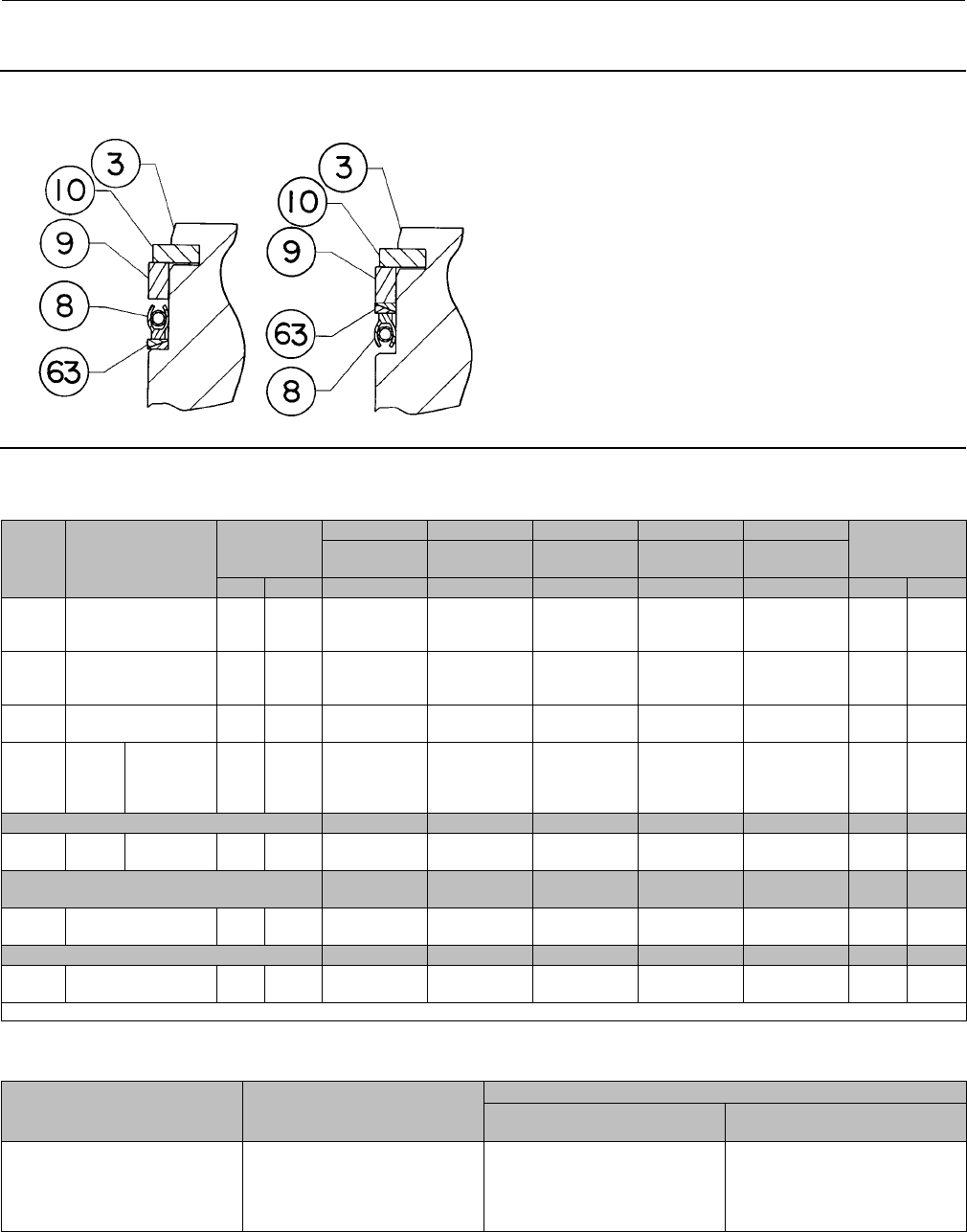
Instruction Manual
D100394X012
EH (1-1/2x1 through 8x6)
December 2014
49
Figure 22. NPS 3 to 6 Fisher EHT Valve Using PEEK Anti-Extrusion Rings
21B2120-A
A7132 FLOW UP FLOW DOWN
Keys 5*, 8*, 9*, 10*, and 63* Fisher EHT Above 450_F(232_C) Using PEEK(1) Anti-Extrusion Rings (see figure 22)
VALVE
SIZE,
NPS
TRIM
PORT
DIAMETER
KEY 63 KEY 8 KEY 9 KEY 10 KEY 3 STEM
CONNECTOR
DIAMETER
Anti-Extrusion
Ring
Seal
Ring
Back-Up
Ring
Retaining
Ring
Anti-Extrusion
Valve Plug
mm Inches PEEK N10276/PTFE S41600 S30200 S41600 mm Inches
3Std,
Whisper III 73.0 2.875
22B2617X012
22B2617X012
22B2617X012
10A4215X032
10A4215X032
10A4215X032
10A4217X012
10A4217X012
10A4217X012
10A4219X012
10A4219X012
10A4219X012
31B2148X012
31B2149X012
31B2150X012
12.7
19.1
25.4
1/2
3/4
1
4
Std,
Whisper III
A,B,C
92.1 3.625 21B2115X012
21B2115X012
16A5485X062
16A5485X062
16A5483X012
16A5483X012
16A5484X012
16A5484X012
31B2151X012
31B2152X012
19.1
25.4
3/4
1
4Whisper III
D73.0 2.875 22B2617X012
22B2617X012
10A4215X032
10A4215X032
10A4217X012
10A4217X012
10A4219X012
10A4219X012
31B2102X012
31B2103X012
19.1
25.4
3/4
1
6Std
DIA B
DIA B
DIA B
DIA B
136.
55.375
21B9342X012
21B9342X012
21B9342X012
21B9342X012
10A5411X032
10A5411X032
10A5411X032
10A5411X032
10A5409X012
10A5409X012
10A5409X012
10A5409X012
10A5410X012
10A5410X012
10A5410X012
10A5410X012
31B2153X012
31B2154X012
31B2155X012
31B2156X012
19.1
25.4
31.8
50.8
3/4
1
1-1/4
2
PEEK N10276/PTFE S41600 S30200 S17400 H900
6Std Diverter 136.
55.375 21B9342X012 10A5411X032 10A5409X012 10A5410X012 31B2131X012 50.8 2
PEEK N10276/PTFE S41600 S30200 S17400
H900/Diverter
6Whisper III
A,B,C
136.
55.375 21B9342X012
21B9342X012
10A5411X032
10A5411X032
10A5409X012
10A5409X012
10A5410X012
10A5410X012
31B2132X012
31B2133X012
25.4
31.8
1
1-1/4
PEEK N10276/PTFE S41600 S30200 S17400 H900
6Whisper III
D
111.
14.375 21B9341X012
21B9341X012
10A4223X032
10A4223X032
10A4224X012
10A4224X012
10A4225X012
10A4225X012
31B2134X012
31B2135X012
25.4
31.8
1
1-1/4
1. PolyEtherEtherKetone.
Key 11* Cage Gasket (2 req'd)
VALVE BODY
RATING,
CLASS
VALVE
SIZE,
NPS
MATERIAL
N04400,
Silver Plated
N04400, Tin Plated
For NACE MR0175-2002
2500
1-1/2 x 1, 2 x 1
3x2
3, 4 x 3
4, 6 x 4
6, 8 x 6
26A5316X012
26A5318X012
26A5320X012
26A5322X012
29A9219X012
26A5316X022
26A5318X022
26A5320X022
26A5322X022
29A9219X022
*Recommended spare parts

Instruction Manual
D100394X012
EH (1-1/2x1 through 8x6)
December 2014
50
TSO Parts for Fisher EHS and EHT Valves (Keys 2*, 6*, and 3*)
VALVE
SIZE CLASS
PORT
DIA TVL TRIM
STEM
DIAMETER ACTUATOR
GROUP
CHARACTER-
ISTIC
CAGE SEAT RING PLUG/
STEM ASSY
NPS Inch Inch mm Inch Key 2 Key 6 Key 3
6EHT 2500 4.1875 3.75
810 19.1 3/4 401, 402, 403
Cavitrol III
3-Stage
37A4432X012 38B1892X012 38B1889X012
816 401, 402, 403 37A4432X022 38B2265X012 38B1889X022
810
25.4 1
404
405
406
407
37A4432X012 38B1892X012
38B2263X012
38B2263X022
38B2263X032
38B2263X042
816
404
405
406
407
37A4432X022 38B2265X012
38B2263X052
38B2263X062
38B2263X072
38B2263X082
6EHT 2500 4.1875
2&3
812
19.1 3/4
1Linear
Equal %
42B3573X012
42B3576X012 38B2267X012 38B2273X012
818 1Linear
Equal %
42B3575X012
42B3578X012 38B2268X012 38B2273X022
2
812 25.4 1
100 Linear
Equal %
42B3573X012
42B3576X012
38B2267X012
38B1869X012
3100 Linear
Mod Equal %
42B3573X012
42B3576X012 38B1869X022
3101 Linear
Mod Equal %
42B3573X012
42B3576X012 38B1869X022
2
818 25.4 1
100 Linear
Equal %
42B3575X012
42B3578X012
38B2268X012
38B1869X032
3100 Linear
Mod Equal %
42B3575X012
42B3578X012 38B1869X042
3101 Linear
Mod Equal %
42B3575X012
42B3578X012 38B1869X042
*Recommended spare parts

Instruction Manual
D100394X012
EH (1-1/2x1 through 8x6)
December 2014
51
TSO Parts for Fisher EHS and EHT Valves (Keys 8*, 63*, 9*, and 10*)
VALVE
SIZE CLASS
PORT
DIA TVL TRIM
STEM
DIAMETER ACTUATOR
GROUP
CHARACTER-
ISTIC
SEAL RING ANTI-EXT
RING BACKUP RING RETAINING
RING
NPS Inch Inch mm Inch Key 8 Key 63 Key 9 Key 10
6EHT 2500 4.1875 3.75
810 19.1 3/4 401, 402, 403
Cavitrol III
3-Stage
10A4223X142 21B9341X012 10A4224X012 10A4225X012
816 401, 402, 403 10A4223X142 21B9341X012 10A4224X022 10A4225X062
810
25.4 1
404
405
406
407
10A4223X142 21B9341X012 10A4224X012 10A4225X012
816
404
405
406
407
10A4223X142 21B9341X012 10A4224X022 10A4225X062
6EHT 2500 4.1875
2&3
812
19.1 3/4
1Linear
Equal % 10A4223X142 21B9341X012 10A4224X012 10A4225X012
818 1Linear
Equal % 10A4223X142 21B9341X012 10A4224X022 10A4225X062
2
812 25.4 1
100 Linear
Equal %
10A4223X142 21B9341X012 10A4224X012 10A4225X012
3100 Linear
Mod Equal %
3101 Linear
Mod Equal %
2
818 25.4 1
100 Linear
Equal %
10A4223X142 21B9341X012 10A4224X022 10A4225X062
3100 Linear
Mod Equal %
3101 Linear
Mod Equal %
Key 12* Seat Ring Gasket or Seat Ring O-Ring
VALVE
BODY
RATING,
CLASS
VALVE
SIZE,
NPS
GASKET O-RING
For All Gasketed Seat
Ring Constructions
For All O-Ring Seat Ring Constructions
Without Cavitrol III Trim
For Cavitrol III
Trim Only
S31600
(316SST)/Graphite
Ethylene
Propylene
Nitrile For NACE
MR0175-2002
Fluoroelastomer
For NACE MR0175-2002
Ethylene
Propylene
2500
1-1/2 x 1, 2 x 1
3x2
3, 4 x 3
4, 6 x 4
6, 8 x 6
10B4657X012
19A2542X012
18A8274X012
19A4321X012
18A2812X012
1H8498X0072
1C6280X0042
1U2504X0062
1H6247X0072
1P5586X0042
1H849806992
1C6280X0052
1U2504X0042
1H624706992
1P5586X0032
1H8498X0032
1C6280X0012
1U250406382
1H6247X0032
1P5586X0022
1H8498X0072
1C6280X0042
1U2504X0062
1H6247X0072
1P5586X0042
Key 26* O-Ring, Ethylene Propylene (for Cavitrol III Trim Only)
VALVE
SIZE, NPS
CL2500
2-Stage 3-Stage
1-1/2 x 1, 2 x 1
3x2
3&4x3
4&6x4
6&8x6
18A5457X022
1E8458X0042
1H2917X0022
1N9563X0032
19A5774X012
---
10A0037X022
1K1365X0082
1H6247X0052
19A5774X012
*Recommended spare parts

Instruction Manual
D100394X012
EH (1-1/2x1 through 8x6)
December 2014
52
Actuator Groups by Type Number
Group 1
54 mm (2-1/8 Inch),
71 mm (2-13/16 Inch),
or 90 mm (3-9/16 Inch) Yoke Boss
Group 101
127 mm (5 Inch) Yoke Boss
Group 404
127 mm (5 Inch, 5H) Yoke Boss
101.6mm(4Inch)Maximum
Travel
Group 408
177.8 mm (5H, 7 Inch) Yoke
Boss
101.6 mm (4 Inch) Maximum
Travel
472 & 473
585C, 585CR (50.8 mm [2 inch] maximum
travel)
1B & 655
657 & 667–76.2 mm (3 Inch) maximum
travel
657-4, 667-4 (76.2 mm [3 inch] travel)
1008–Except 90 mm (3-9/16 Inch) yoke
boss with 50.8 mm (2 inch) travel
3024C, 3025
685SE, 685SR (76.2 mm [3 inch] maximum
travel)
667, 667 MO 667, 667-4
3025 (ATO)
657 Size 100
1008 Size 100
3025 (ATC)
Group 401
90.5 mm (3-9/16 Inch)
Yoke Boss
88.9 to 101.6 mm (3.25 to 4 inch)
Travel
Group 405
127 mm (5 Inch, 5H) Yoke Boss
101.6mm(4Inch)Maximum
Travel
Group 409
177.8 mm (5H, 7 Inch) Yoke
Boss
101.6 mm (4 Inch) Maximum
Travel
657, 657 MO
667, 667 MO
657-4, 657-4 MO
667-4, 667-4 MO
3025
685SE, 685SR
657 MO, 657-4 MO 667 Size 100
3025 (ATO)
Group 406
127 mm (5 Inch, 5H) Yoke Boss
101.6mm(4Inch)Maximum
Travel
Group 801
90.5 mm (3-9/16 Inch)
Yoke Boss
203.2 mm (8 Inch) Maximum
Travel
667 MO, 667-4 MO 585C, 585C MO Size 60
685SE, 685SR
Group 100
127 mm (5 Inch, 5H) Yoke Boss
Group 402
90.5 mm (3-9/16 Inch)
Yoke Boss
101.6 mm (4 Inch) Maximum
Travel
Group 407
127 mm (5 Inch, 5H) Yoke Boss
101.6mm(4Inch)Maximum
Travel
Group 802
127 mm (5 Inch, 5H)
Yoke Boss
203.2 mm (8 Inch) Maximum
Travel
472, 473
585C, 585C MO
657, 657 MO
1008 PDTC
585C MO Size 60
585C, 585C MO
657
3025 (ATC)
685SE, 685SR
585C, 585C MO
685SE, 685SR
Group 403
90.5 mm (3-9/16 Inch)
Yoke Boss
101.6 mm (4 Inch) Maximum
Travel
585C Size 60
1008 Size 50
*Recommended spare parts
Emerson Process Management
Marshalltown, Iowa 50158 USA
Sorocaba, 18087 Brazil
Chatham, Kent ME4 4QZ UK
Dubai, United Arab Emirates
Singapore 128461 Singapore
www.Fisher.com
The contents of this publication are presented for informational purposes only, and while every effort has been made to ensure their accuracy, they arenot
to be construed as warranties or guarantees, express or implied, regarding the products or services described herein or their use or applicability. All sales are
governed by our terms and conditions, which are available upon request. We reserve the right to modify or improve the designs or specifications of such
products at any time without notice.
E1981, 2014 Fisher Controls International LLC. All rights reserved.
Fisher, Cavitrol, ENVIRO-SEAL, and Whisper Trim are marks owned by one of the companies in the Emerson Process Management business unit of Emerson
Electric Co. Emerson Process Management, Emerson, and the Emerson logo are trademarks and service marks of Emerson Electric Co. All other marks are
the property of their respective owners.
Neither Emerson, Emerson Process Management, nor any of their affiliated entities assumes responsibility for the selection, use or maintenance
of any product. Responsibility for proper selection, use, and maintenance of any product remains solely with the purchaser and end user.
