Emerson Fisher V260 Data Sheet
2015-03-30
: Emerson Emerson-Fisher-V260-Data-Sheet-680487 emerson-fisher-v260-data-sheet-680487 emerson pdf
Open the PDF directly: View PDF ![]() .
.
Page Count: 8
www.Fisher.com
FisherrV260 Ball Control Valve
TheFisherV260isafull-borecontrolvalvedesigned
fromthegroundupwithfeaturesforoptimized
pressure, flow and process control. An integral drilled
attenuator controls noise and vibration from high
pressure drop liquids and gases. The splined shaft
connection to the actuator reduces lost motion.
The V260A with Aerodome attenuator, V260B with
Hydrodome attenuator, and V260C Ball Control Valves
(figures 1 and 3) combine the efficiency of a rotary
valve with the energy-dissipating capability of a special
trim to provide improved performance for demanding
applications. The valve is available with single, dual, or
dual block-and-bleed seal options (see the
Specifications table).
ThetrimdesignoftheV260Aisusedingasserviceto
reduce noise effects that cause pipeline vibration. The
V260B provides improved performance for demanding
applications such as pump bypass and pipeline
take-off. The trim is designed for liquid service to help
eliminate or reduce cavitation and associated pipeline
noise and vibration. The V260C full-bore ball valve is
designed for automated control in bypass, batch,
monitor, and emergency shutoff service applications,
and it presents little or no restriction to flow.
The V260 full-bore ball valve is available with
composition seals, and process type stem packing for
improved service life.
Unless otherwise noted, all NACE references are to
NACE MR0175-2002.
Features
Excellent Flow Control-- The splined ball to shaft
connection, splined shaft to actuator connection,
double power-end bushing assemblies, and
trunnion guiding, all provide improved dynamic
control.
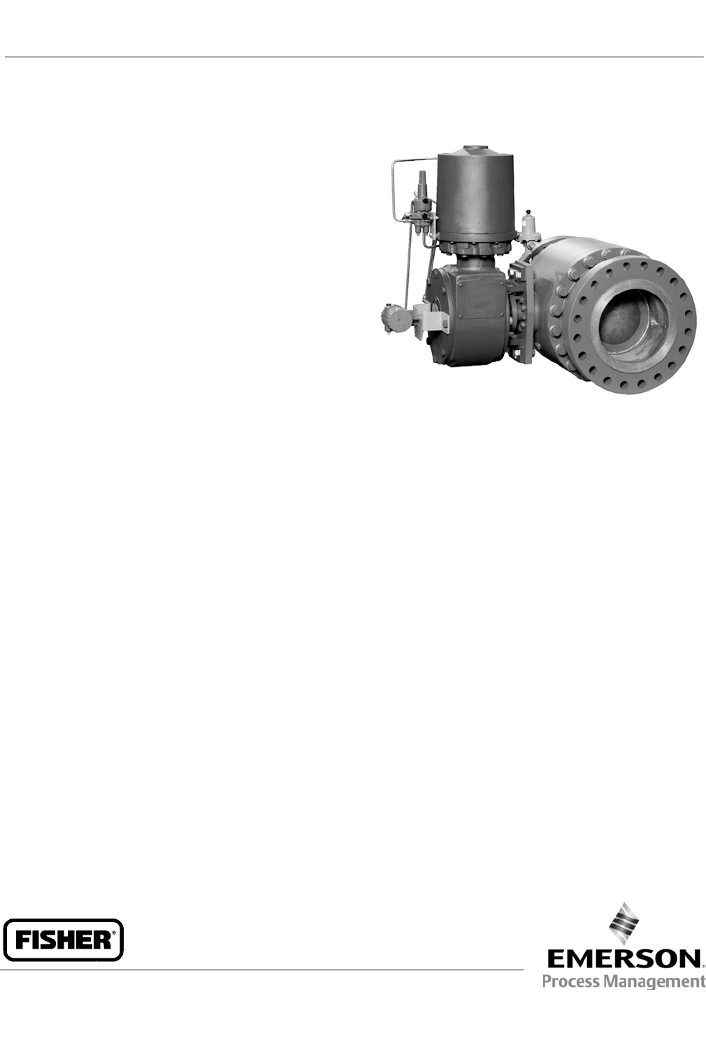
W6539
Fisher V260 Valve
Aerodynamic Performance-- Up to -20 dBA
acoustical attenuation can be achieved for the
V260A within a single stage construction.
Dual-stage construction can provide up to -25 dBA
attenuation.
Improved Service Life-- The attenuator is not part of
the seal assembly. The seal wipes to ball surface, not
the attenuator, promoting increased service life.
Trim Versatility-- Key valve components, such as
valve body, ball, shaft and bearings, are
interchangeable between the V260A, V260B and
V260C. This feature allows you to reduce your spare
parts inventory and maintenance time.
(continued on page 2)
V260 Valve
D102352X012
Product Bulletin
51.3:V260
July 2014

V260 Valve
D102352X012
Product Bulletin
51.3:V260
July 2014
2
Specifications
Valve Body Sizes and End Connection Styles
NPS J8, J10, J12, J16, J20, and J24 flanged
valves with CL150, CL300, or CL600 raised-face
flanges compatible with ASME B16.5.
Consult your Emerson Process Management sales
office for other end style connections.
Maximum Inlet Pressures and Temperatures(1)
Consistent with CL150, CL300, or CL600
pressure-temperature ratings per ASME B16.34
Maximum Allowable Shutoff Pressure Drop(1).
For Single-Seal and Dual-Seal Construction
(Except where further limited by the pressure-
temperature rating of the valve body):
JCL150: 20 bar (285 psi) at 38_C(100_F)
JCL300: 51 bar (740 psi) at 38_C(100_F)
JCL600: 103 bar (1480 psi) at 38_C(100_F)
Flow Characteristic
JModified linear with single high density attenuator,
JModified equal percentage with single
characterized attenuator (see figure 2), or
JModified equal percentage without attenuator
Flow and Shutoff Direction
Unidirectional flow for V260 is forward flow. Seal is
upstream.
JSingle Seal Constructions: Should be used for
unidirectional flow and unidirectional shutoff only.
JDouble Seal Constructions: V260A and V260C may
be used for unidirectional and bidirectional flow.
V260B should be used for unidirectional flow only for
effective anti-cavitation protection. Bidirectional
shutoff requires the dual seal construction.
Flow Coefficients
See Fisher Catalog 12
Shutoff Classification
Single-Seal Composition Constructions: 0.001% of
maximum valve capacity (less than 10% of ANSI/FCI
70-2 Class IV and IEC 60534-4)
Dual-Seal Composition Constructions: 0.001% of
maximum valve capacity (less than 10% of ANSI/FCI
70-2 Class IV and IEC 60534-4)
Seal Material and Temperature Capability(1)
Standard: JPOM (polyoxymethylene) -29 to 82_C
(-20 to 180_F)
Optional: JPTFE/PEEK(2)(3) -29 to 93_C
(-20 to 200_F)
Maximum Ball Rotation
90 degrees
Actuator Mounting
Right-hand or left-hand mounted as viewed from the
valve inlet for forward flow
Packing Arrangements
PTFE Packing: Standard construction
(see figure 4)
ENVIRO-SEALtPacking: This optional packing
system provides improved sealing, guiding, and
transmission of loading force to control liquid and gas
emissions. Contact your Emerson Process
Management sales office for availability of
ENVIRO-SEAL packing (see figure 4)
Dimensions
Seefigure5
Options
JDouble block-and-bleed applications (Dual-seal
construction is required), JTwo Stage V260A
Attenuator, JTwo or Three Stage V260B Attenuator,
JCL900 flanges, JRing type joint flanges
1. The pressure/temperature limits in this bulletin and any applicable standard or code limitation for this valve should not be exceeded.
2. PTFE stands for Polytetrafluoroethylene, and PEEK stands for PolyEtherEtherKetone.
3. Temperature limit of PTFE/PEEK is limited due to standard Nitrile O-Ring. Contact your Emerson Process Management sales office for higher temperature options, up to 232_C (450_F).
Features (continued)
Sour Service and Sour Crude Oil Capability--
Optional materials are available that comply with
NACE Standard MR0175-2002.
Tight Shutoff-- Self-adjusting seal(s) that are
pressure assisted provide tight shutoff for long
reliable service. The design incorporates a heavy
duty S31600 stainless steel carrier that retains the
composition seal for full-rated pressure drop
service.

V260 Valve
D102352X012
Product Bulletin
51.3:V260
July 2014
3
Heavy Duty Trunnion-- The ball trunnions are
designed for demanding applications requiring long
service life, with a reduction in maintenance time
and costs.
Broad Hydrodynamic Applications-- Single, dual,
and three-stage attenuators for the V260B may be
provided for a varying range of applications. A Kc
value of 1.0 is achievable depending on service
conditions.
Flexible Applications-- The attenuator is active
throughout the ball rotation for very demanding
services or a characterized attenuator is used to
matchtheserviceconditions(seefigure2).
Table 1. Aerodome and Hydrodome Trim Benefits Comparison
Benefits Typical Competitive Device V260A with Aerodome
Attenuator
V260B with Hydrodome
Attenuator
Up to -20 dBA aerodynamic noise attenuation No Yes N/A
Excellent attenuation effect at critical opening position No Yes Yes
High Density (Full) or characterized attenuation No Yes Yes
2or3stageoptions No Yes Yes
Effective bidirectional attenuation option No Yes Yes
Integrated ball, shaft, and attenuator design for best
throttling dynamics No Yes Yes
Dual seal option No Yes Yes
Ball seal exchange without actuator removal No Yes Yes
Kcimproved versus unattenuated device Yes N/A Yes
Double block-and-bleed option No Yes Yes
Overall ease of maintenance No Yes Yes
Trunnion-mounted ball for excellent wear resistance Yes Yes Yes
Low profile for ease of piping Yes Yes Yes
Table 2. Standard Materials of Construction
Part Material
Valve Body LF2 Carbon Steel
Ball WCC Carbon Steel
Seal POM with S31600 SST Seal Blank or PTFE/PEEK with S31600 SST Seal Blank
Dome Attenuator S17400 SST
Shaft S17400 SST H1075 or S17400 SST H1150 DBL
Wave Spring S17700 SST or N07750
Tailpiece LCC Carbon Steel
Tailpiece Mounting Bolting B7 Steel or B7M Steel
Bearing Plate Carbon Steel
Bearings S30400 SST with Aramid liner
Thrust Washer Carbon filled PTFE
Packing Box Housing LCC Carbon Steel
Packing PTFE/Carbon filled PTFE
Packing Bolting B7 Steel, B7M Steel, or B8M Class 2 SST
Packing Follower, Packing Box Ring Annealed S31600 SST
Groove Pins B8M SST
O-Rings Nitrile
Actuator Mounting Bolting Steel Grade 5
V260 Valve
D102352X012
Product Bulletin
51.3:V260
July 2014
4
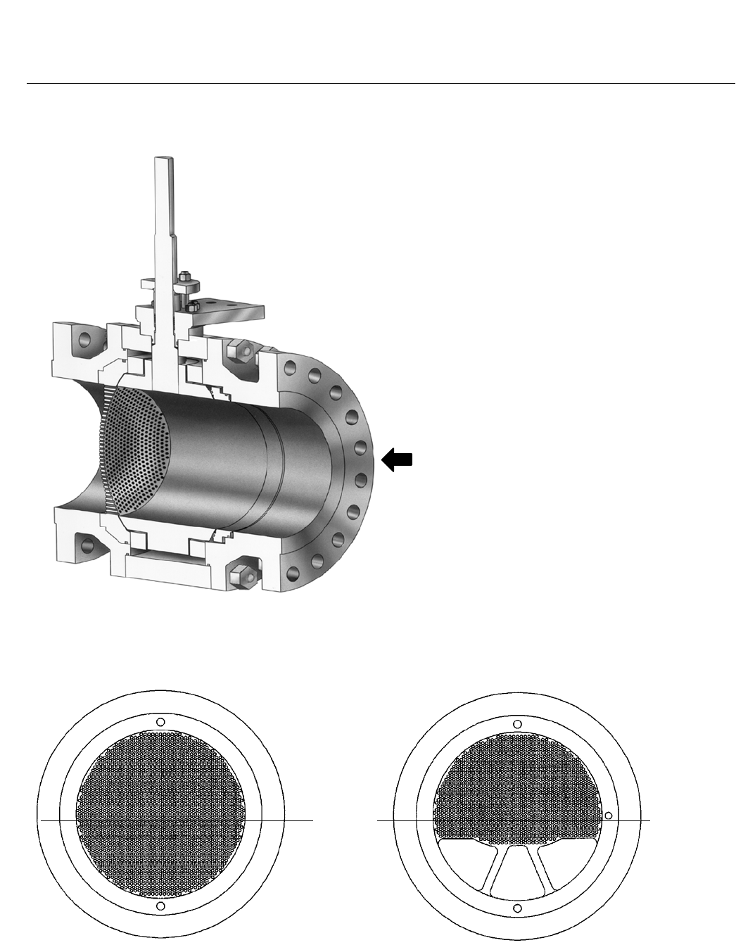
Figure 1. Sectional View of Valve (Single Seal)
W6365-2
FLOW
Figure 2. Aerodome and Hydrodome Attenuator Details
HIGH DENSITY
ATTENUATOR
CHARACTERIZED
ATTENUATOR
47B1309-A
47B1312-A
A6749-2
V260 Valve
D102352X012
Product Bulletin
51.3:V260
July 2014
5
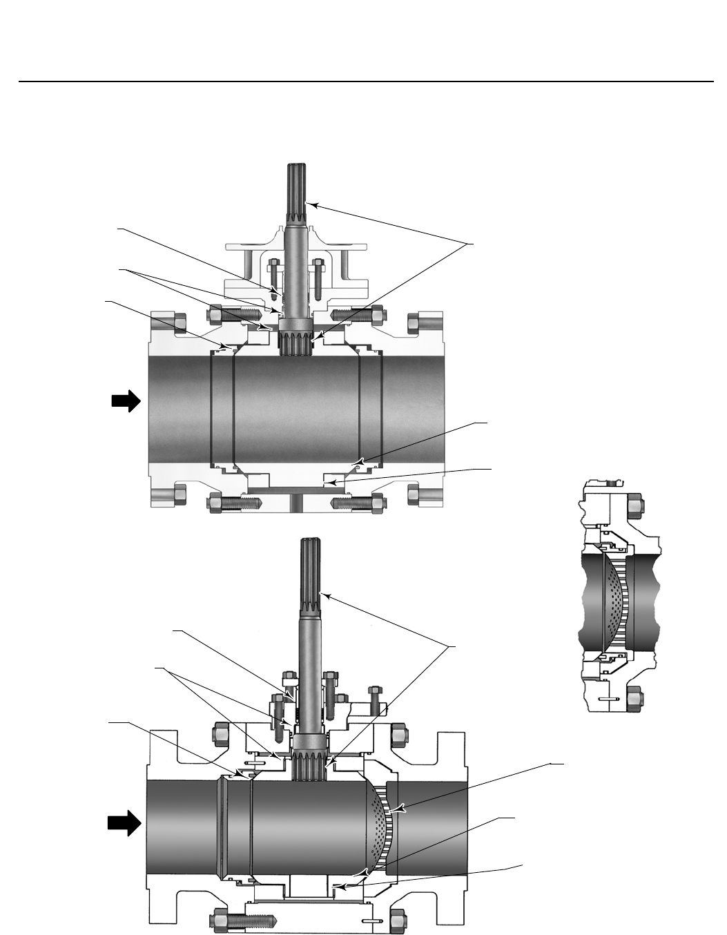
Figure 3. Typical Fisher V260 Valve Assembly
W6521-1*
PTFE
PACKING
PTFE-LINED
BEARING
BALL
SEAL
FLOW
SPLINED
SHAFT
BALL
PTFE-LINED
BEARING
W7509-2/IL
PTFE
PACKING
PTFE-LINED
BEARING
BALL
SEAL
FLOW
SPLINED
SHAFT
AERODOME
ATTENUATOR
BALL
PTFE-LINED
BEARING
W7511-1
V260C WITH DUAL SEAL
V260A OR V260B WITH DUAL SEAL
V260A OR V260B WITH SINGLE SEAL
V260 Valve
D102352X012
Product Bulletin
51.3:V260
July 2014
6
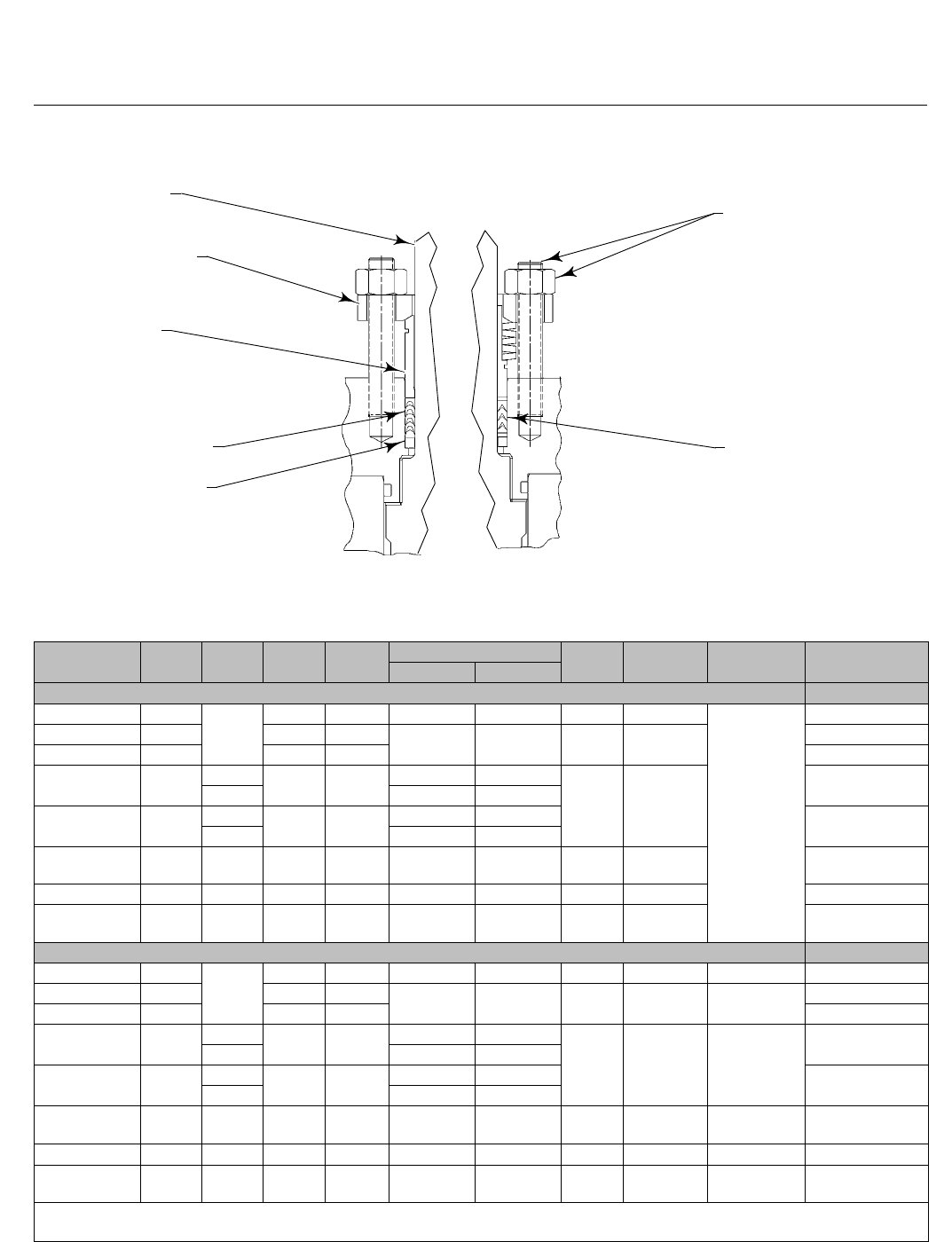
Figure 4. Packing Arrangement Details
PACKING FLANGE
DRIVE SHAFT
PACKING
FOLLOWER
TYPICAL PTFE
V-RING PACKING SET
PACKING BOX RING
PACKING STUD
AND NUT
TYPICAL
ENVIRO-SEAL
PTFE V-RING
PACKING SET
STANDARD PACKING ARRANGEMENT ENVIRO-SEAL PACKING ARRANGEMENT
94BA02200-D
B2472-1
Table 3. Dimensions
VALVE SIZE,
NPS A D K R
ST U W
(THREADED)
APPROXIMATE
WEIGHT
Shaft Dia. Spline Dia.
mm kg
8661
356
273 457 44.4 44.4 273 51
See thread
info below
442
10 788 324 553 63.5 63.5 337 76 703
12 840 369 639 919
16 991 508 508 848 76.2 76.2(1)
533 127
2472
471 76.2 63.5(2)
20 1194 508 602 1040 88.9 88.9(1)
4309
471 88.9 63.5(2)
24 CL150 1397 314 671 1158 88.9 88.9
(keyed shaft) 533 127 5352
24 CL300 1397 508 708 1158 88.9 88.9 533 127 5761
24 CL600 1397 364 708 1241 102 102
(keyed shaft) 610 457 (U1)(3)
254 (U2)(3) 7076
Inches Pounds
826.04
14.00
10.75 18.00 1-3/4 1-3/4 10.75 2.00 3/4-10 975
10 31.04 12.75 21.77 2-1/2 2-1/2 13.25 3.00 7/8-91550
12 33.07 14.53 25.15 2025
16 39.00 20.00 19.99 33.38 3 3(1)
21.00 5.00 1-1/4-8
5450
18.56 3 2-1/2(2)
20 47.00 20.00 23.70 40.96 3-1/2 3-1/2(1)
9500
18.56 3-1/2 2-1/2(2)
24 CL150 55.00 12.38 26.40 45.60 3-1/2 3-1/2
(keyed shaft) 21.00 5.00 1-1/4-811800
24 CL300 55.00 20.00 27.87 45.60 3-1/2 3-1/2 21.00 5.00 1-1/4-812700
24 CL600 55.00 14.32 27.87 48.86 44
(keyed shaft) 24.00 18 (U1)(3)
10 (U2)(3) 1-1/4-815600
1. For 1069 size 100 actuator.
2. For 1061 size 100 actuator.
3. See table 6 for NPS 24 U1 and U2 information.
V260 Valve
D102352X012
Product Bulletin
51.3:V260
July 2014
7
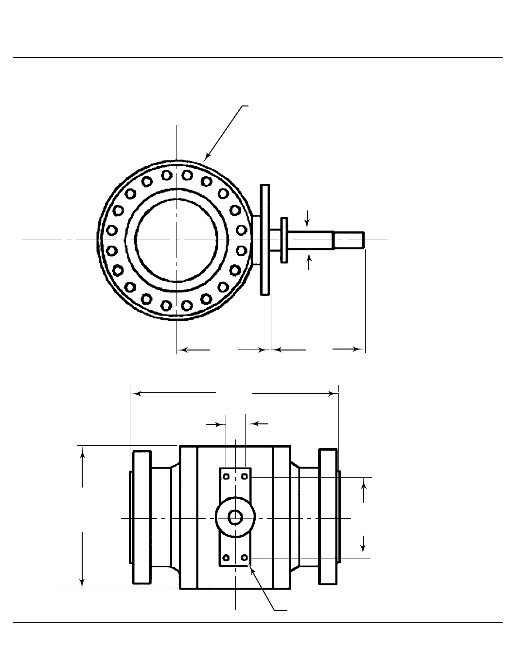
Figure 5. Dimensions (also see table 3)
T
W
R
A
K
S
D
Note:
1. For CL300 valves, face-to-face dimensions are the same as CL600 valves.
2. Valve shown meets CL600 flanges. Flange and bolt dimensions vary for CL300 valves.
MATCHES CL600(1) FLANGES
14B0995-B
U
V260 Valve
D102352X012
Product Bulletin
51.3:V260
July 2014
8
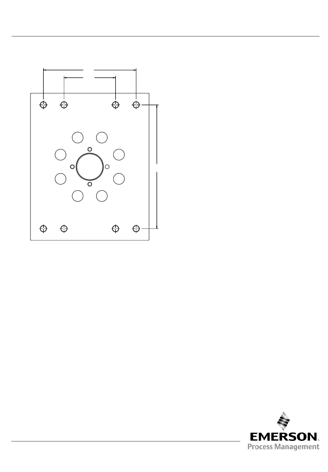
Figure 6. NPS 24 Additional Dimensions (also see table 3)
T
U1
U2
Emerson Process Management
Marshalltown, Iowa 50158 USA
Sorocaba, 18087 Brazil
Chatham, Kent ME4 4QZ UK
Dubai, United Arab Emirates
Singapore 128461 Singapore
www.Fisher.com
The contents of this publication are presented for informational purposes only, and while every effort has been made to ensure their accuracy, they arenot
to be construed as warranties or guarantees, express or implied, regarding the products or services described herein or their use or applicability. All sales are
governed by our terms and conditions, which are available upon request. We reserve the right to modify or improve the designs or specifications of such
products at any time without notice.
E1990, 2014 Fisher Controls International LLC. All rights reserved.
Fisher and ENVIRO-SEAL are marks owned by one of the companies in the Emerson Process Management business unit of Emerson Electric Co. Emerson
Process Management, Emerson, and the Emerson logo are trademarks and service marks of Emerson Electric Co. All other marks are the property of their
respective owners.
Neither Emerson, Emerson Process Management, nor any of their affiliated entities assumes responsibility for the selection, use or maintenance
of any product. Responsibility for proper selection, use, and maintenance of any product remains solely with the purchaser and end user.
