Emerson Fisher Vee Ball V150 Instruction Manual
2015-03-30
: Emerson Emerson-Fisher-Vee-Ball-V150-Instruction-Manual-680588 emerson-fisher-vee-ball-v150-instruction-manual-680588 emerson pdf
Open the PDF directly: View PDF ![]() .
.
Page Count: 56
www.Fisher.com
FisherrVee-BalltV150, V200 and V300 Rotary
Control Valves NPS 1 through 12
Contents
Introduction 1.................................
Scope of Manual 1.............................
Description 2.................................
Educational Services 2...........................
Specifications 2...............................
Educational Services 2...........................
Installation 2....................................
Maintenance 7..................................
Packing Maintenance 7.........................
Replacing the Ball Seal 9........................
Disassembly 9.............................
Assembly 12..............................
HDMetalSealLubrication 18................
Bearing and Ball Maintenance 18.................
NPS3through12valve 18......................
Welded Taper Key Replacement 21...........
NPS 1 through 2 valves 23......................
Actuator Mounting 29
............................
NPS3through12withoutAttenuator 29...........
Determining Mounting Position 30...............
Determining Closed Position 30.................
Parts Ordering 36
................................
Parts Kits 38.....................................
Parts List 39.....................................
Appendix A Instructions for Non-Series B 46.........
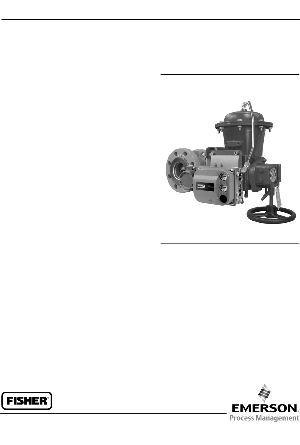
Figure 1. Fisher Vee-Ball with 1052 Actuator
and FIELDVUE™ DVC6200 Digital Valve Controller
X0177
Introduction
Scope of Manual
This instruction manual provides installation, operation, maintenance, and parts information for the Fisher Vee-Ball
V150 (NPS 1 through 12), V200 (NPS 1 through 10), and V300 (NPS 1 through 12) rotary control valves (see figure 1).
NPS 3 through 12 valves without an attenuator currently in production are referred to as Series B (for more
information on this distinction see Appendix A).
For larger valves (NPS 14, 16, and 20), refer to a separate instruction manual. For information on ENVIRO-SEALt
packing, see the ENVIRO-SEAL Packing System for Rotary Valves instruction manual (D101643X012). Refer to separate
manuals for information concerning the actuator, positioner and accessories.
Do not install, operate, or maintain Vee-Ball valves without being fully trained and qualified in valve, actuator, and
accessory installation, operation, and maintenance. To avoid personal injury or property damage, it is important to
carefully read, understand, and follow all the contents of this manual, including all safety cautions and warnings. If you
have any questions about these instructions, contact your Emerson Process Management sales office before
proceeding.
Instruction Manual
D101554X012
Vee-Ball Valves
January 2015
Instruction Manual
D101554X012
Vee-Ball Valves
January 2015
2
Table 1. Specifications
Valve Sizes and End Connection Styles
V150: NPS J1, J1-1/2, J2, J3, J4, J6, J8,
J10, and J12 with CL150 raised-face flanges
V200: NPS J1, J1-1/2, J2, J3, J4, J6, J8,
and J10 flangeless valves that mate with CL150,
300, or 600 (for NPS 1 through 8) raised-face flanges
V300: NPS J1, J1-1/2, J2, J3, J4, J6, J8,
J10, and J12 valves with CL300 raised-face flanges
Maximum Inlet Pressure(2)
Consistent with applicable ASME B16.34 or
EN 12516-1 ratings
Standard Flow Direction
Forward (into the convex face of the Vee-ball)
Actuator Mounting
JRight-hand, standard or Jleft-hand, optional, as
viewed from upstream end of valve (see figure 23 and
the Actuator Mounting section)
Maximum Ball Rotation
Standard: Ball rotates counterclockwise to close
when viewed from actuator side of valve
Optional: Ball rotates clockwise to close
Ball rotation is 90 degrees
Valve/Actuator Action
With diaphragm or piston rotary actuator,
field-reversible between:Jpush-down-to-close
(extending actuator rod closes valve) and
Jpush-down-to-open (extending actuator rod
opens valve.) See actuator manual for details
1. The pressure/temperature limits in this manual, and any applicable code or standard limitation, should not be exceeded.
Description
The V150, V200, and V300 Vee-Ball valves (figure 1) with a V-notch ball are used in throttling or on-off service. The
V200 is a flangeless construction. The V150 and V300 valves are raised-face flanged constructions. The splined valve
shaft of all these valves connect to a variety of rotary-shaft actuators.
Specifications
Specifications for these valves are shown in table 1 and in bulletin 51.3:Vee-Ball.
Educational Services
For information on available courses for Fisher Vee-Ball valves, as well as a variety of other products, contact:
Emerson Process Management
Educational Services - Registration
Phone: 1-641-754-3771 or 1-800-338-8158
E-mail: education@emerson.com
http://www.emersonprocess.com/education
Installation
Separate installation steps are provided in this section for V150 and V300 flanged valves, and for V200 flangeless
valves. Key numbers in installation procedures are shown in figures 24, 25 and 26 unless otherwise indicated.
Some types of ceramic trim, including VTC, can create a spark under certain conditions. If an edge of a ceramic part is
struck against a second ceramic part with enough force, it can produce a spark.
Instruction Manual
D101554X012
Vee-Ball Valves
January 2015
3
WARNING
Avoid personal injury and property damage from ignition of process fluid caused by sparks from ceramic trim. Do not use
ceramic trim where the process fluid is unstable or if it is an explosive mixture (such as ether and air).
WARNING
Always wear protective gloves, clothing, and eyewear when performing any installation operations to avoid personal
injury.
Personal injury or equipment damage caused by sudden release of pressure may result if the valve assembly is installed
where service conditions could exceed either the valve body rating or the mating pipe flange joint rating. To avoid such
injury or damage, provide a relief valve for overpressure protection as required by government or accepted industry codes
andgoodengineeringpractices.
Check with your process or safety engineer for any additional measures that must be taken to protect against process
media.
If installing into an existing application, also refer to the WARNING at the beginning of the Maintenance section in this
instruction manual.
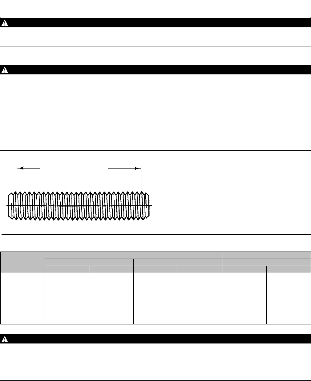
Figure 2. Flange Stud Length for Seal Protector End
DIMENSION SHOWN IN TABLE 2
1A4520
FIRST FULL THREAD TO
FIRST FULL THREAD
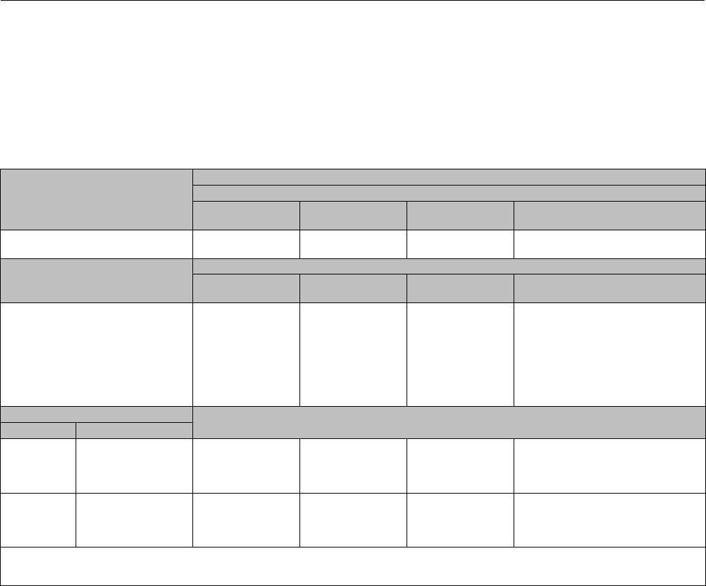
Table 2. Flange Stud Lengths Required for Seal Protector Ring End of Fisher V150 and V300 Valves
VALVE
SIZE,
NPS
V150 V300
ANSI/ISA S75.08.02 Face-to-Face ASME B16.10 Short Face-to-Face ANSI/ISA S75.08.02 Face-to-Face
mm Inches mm Inches mm Inches
1
1-1/2
2
3
4
6
8
10
12
70
83
95
95
108
114
121
133
140
2.75
3.25
3.75
3.75
4.25
4.50
4.75
5.25
5.50
95
127
146
133
146
152
171
165
159
3.75
5.00
5.75
5.25
5.75
6.00
6.75
6.50
6.25
89
102
95
121
127
140
152
171
184
3.50
4.00
3.75
4.75
5.00
5.50
6.00
6.75
7.25
WARNING
When ordered, the valve configuration and construction materials were selected to meet particular pressure, temperature,
pressure drop, and controlled fluid conditions. Responsibility for the safety of process media and compatibility of valve
materials with process media rests solely with the purchaser and end-user. To avoid possible personal injury and because
some valve/trim material combinations are limited in their pressure drop and temperature ranges, do not apply any other
conditions to the valve without first contacting your Emerson Process Management sales office.
Instruction Manual
D101554X012
Vee-Ball Valves
January 2015
4
WARNING
The valve drive shaft is not necessarily grounded to the pipeline when installed. Personal injury or property damage could
result from an explosion caused by a discharge of static electricity from valve components if the process fluid or the
atmosphere around the valve is flammable. If the atmosphere around the valve or the process fluid is flammable,
electrically bond the drive shaft to the valve.
Note
Standard PTFE packing is composed of a partially conductive carbon-filled PTFE female adaptor with PTFE V-ring packing. Standard
graphite packing is composed of all conductive graphite ribbon packing. Alternate shaft-to-valve body bonding is available for
hazardous service areas where the standard packing is not sufficient to bond the shaft to the valve (see the following step).
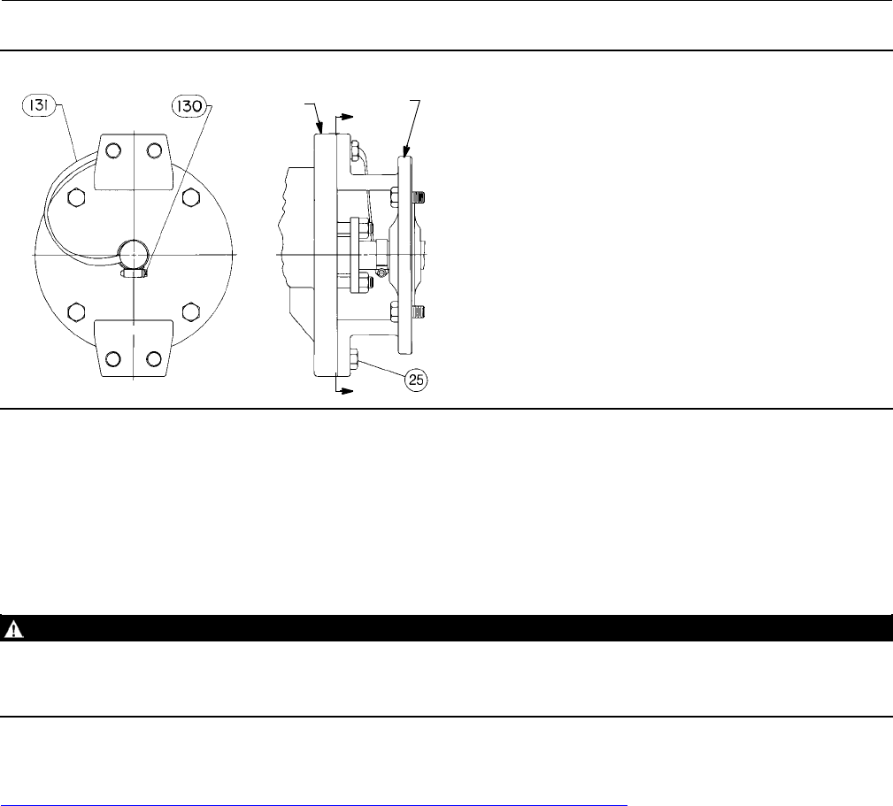
Attach the optional bonding strap assembly (key 131, figure 3) to the valve drive shaft (key 6) with the clamp (key 130,
figure 3) and connect the other end of the bonding strap assembly to the valve body with the cap screw (key 23).
1. If the valve is to be stored before installation, protect theflangematingsurfacesandkeepthevalvebodycavitydry
and free of foreign material.
2. Install a three-valve bypass around the control valve assembly if continuous operation will be necessary during
inspection and maintenance of the valve.
3. The valve is normally shipped as part of a control valve assembly, with an actuator mounted on the valve. If the
valve and actuator have been purchased separately or if the actuator has been removed, mount the actuator
according to the Actuator Mounting section and the appropriate actuator instruction manual.
4. Standard flow direction is with the seal protector ring (key 3) facing upstream.
5. Install the valve in a horizontal or vertical pipeline with the drive shaft in a horizontal position.
CAUTION
Do not allow the valve to be installed in the pipeline with the drive shaft in the vertical position because of excessive wear
to valve component parts.
6. The actuator can be right- or left-hand mounted with the shaft in a horizontal orientation as shown in figure 1. If
necessary, refer to the appropriate actuator instruction manual for actuator installation and adjustment
procedures.
CAUTION
Ensure the valve and adjacent pipelines are free of foreign material that could damage the valve seating surfaces.
7. Be certain the valve and adjacent pipelines are free of any foreign material that could damage the valve sealing
surfaces.
8. Be sure the pipeline flanges are in line with each other.
Installing V150 and V300 Valves
1. Install the V150 and V300 valve using studs (keys 32 and 33, not shown) and nuts to connect the valve flanges to
the pipeline flanges. The seal protector ring (key 3) end of the valve requires longer line flange studs (key 32) than
standard. Do not use standard-length line flange studs for the seal protector ring end of the valve.
Instruction Manual
D101554X012
Vee-Ball Valves
January 2015
5
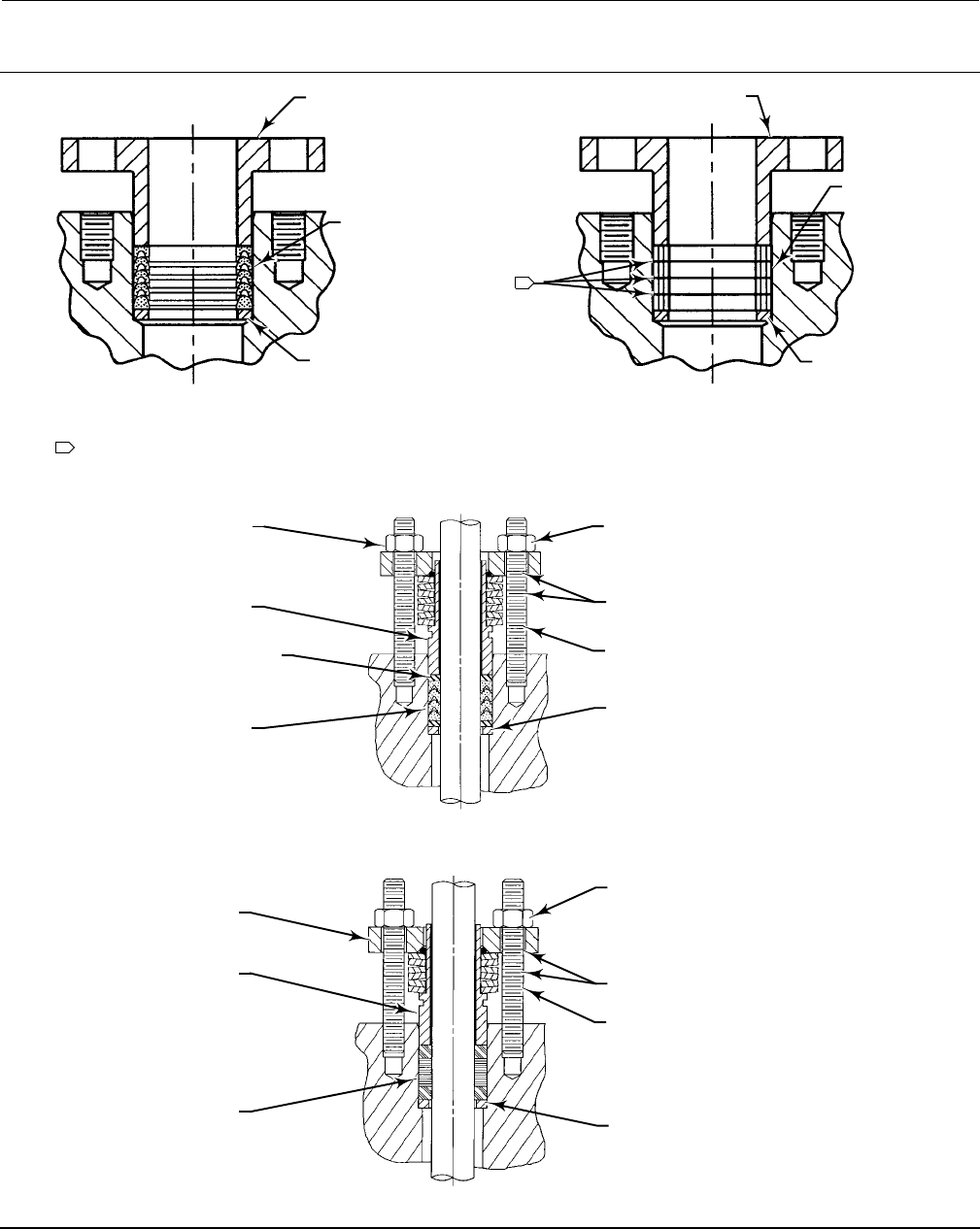
Figure 3. Optional Shaft-to-Body Bonding Strap Assembly
VALVE
BODY
ACTUATOR
A
A
VIEW A-A
37A6528-A
A3143-2
2. See table 2 and figure 2 for length of studs for the seal protector ring end of V150 and V300 valves. Lubricate the
studs with anti-seize lubricant.
3. Insert flat-sheet line flange gaskets (or spiral-wound gaskets with compression-controlling center rings) that are
compatible with the flowing media.
4. Connect pressure lines to the actuator as indicated in the actuator instruction manual. When an auxiliary manual
actuator is used with a power actuator, install a bypass valve on the power actuator (if one is not supplied) for use
during manual operation.
WARNING
Personal injury could result from packing leakage. Valve packing was tightened before shipment; however the packing
might require some readjustment to meet specific service conditions. Check with your process or safety engineer for any
additional measures that must be taken to protect against process media.
If the valve has ENVIRO-SEAL live-loaded packing installed, this initial re-adjustment will probably not be required. See
ENVIRO-SEAL Packing System for Rotary Valves instruction manual (D101643X012) for packing instructions.
Installing V200 Valves
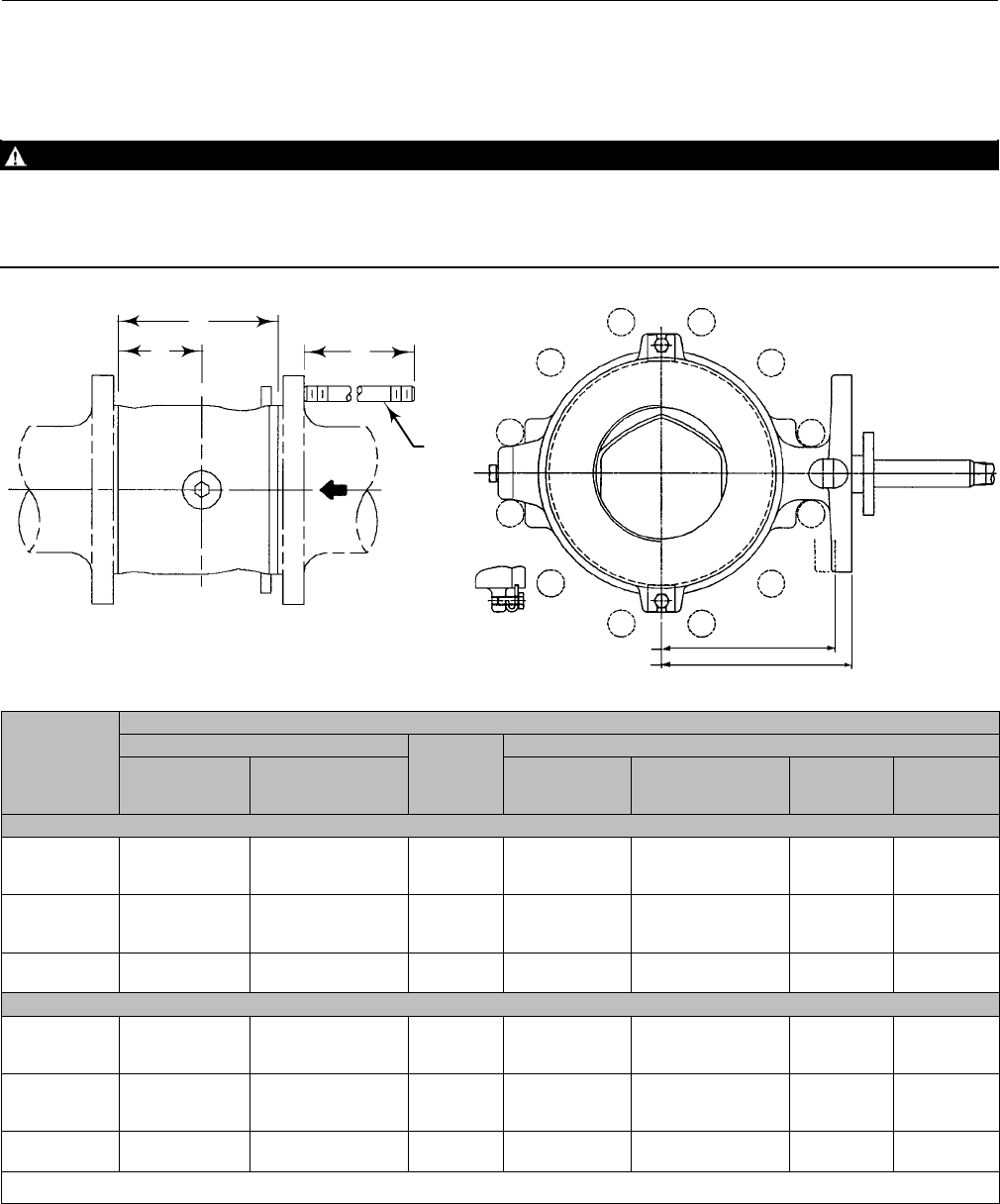
Stud length dimensions are shown in figure 4 for the seal protector ring end of the valve. For V200, CL600, the
dimensionfromthecenterlineofthevalveboretothemountingflangefaceislargerthanaCL150or300valve.
1. Install the V200 valve using long studs (key 32, figure 4) to connect the two pipeline flanges. Refer to figure 4 for
the size of studs required. Lubricate the studs with anti-seize lubricant.
2. Install two studs in the flanges before you place the valve in the line. Place the two studs so they will contact the
line-centering notches at the bottom of the valve body.
3. Insert flat-sheet line flange gaskets (or spiral-wound gaskets with compression-controlling center rings) that are
compatible with the process fluid.
4. Place the valve on the two studs. Install all remaining studs. Measure carefully to be sure the valve is centered on the
pipelineflanges,andtightentheflangestudnuts.Tightenthenutsinacriss-crosssequencetobesuretheflange
gaskets are properly torqued.
Instruction Manual
D101554X012
Vee-Ball Valves
January 2015
6
5. Connect pressure lines to the actuator as indicated in the actuator instruction manual. When an auxiliary manual
actuator is used with a power actuator, install a bypass valve on the power actuator (if one is not supplied) for use
during manual operation.
WARNING
Personal injury could result from packing leakage. Valve packing was tightened before shipment; however the packing
might require some readjustment to meet specific service conditions. Check with your process or safety engineer for any
additional measures that must be taken to protect against process media.
Figure 4. Fisher V200 Dimensions and Required Clearances for Installation
179 mm (7.06 INCHES) FOR CL600 NPS 6 VALVES
164 mm (6.44 INCHES) FOR CL150 AND 300 NPS 6 VALVES
95BA02100B
A6956
A
BM
KEY
32
12B3060-L
V200
VALVE
SIZE,
NPS
DIMENSION
A
B
M
Standard
ANSI/ISA
S75.08.02(1)
CL150
ASME B16.10(2)
Short (Optional)
Standard
CL150 ANSI/ISA
S75.08.02(1)
CL150
ASME B16.10(2)
Short (Optional)
CL300 CL600
mm
1
1-1/2
2
102
114
124
127
165
178
58
64
57
176
189
211
202
240
268
202
224
237
202
224
237
3
4
6
165
194
229
203
229
267
87
92
119
254
286
343
286
321
381
279
305
362
286
343
423
8
10
243
297
292
330
119
151
343
419
394
451
387
---
426
---
Inches
1
1-1/2
2
4.00
4.50
4.88
5.00
6.50
7.00
2.29
2.50
2.25
6.94
7.44
8.31
7.94
9.44
10.56
7.94
8.81
9.31
7.94
8.81
9.31
3
4
6
6.50
7.62
9.00
8.00
9.00
10.50
3.44
3.62
4.69
10.00
11.25
13.50
11.25
12.62
15.00
11.00
12.00
14.25
11.25
13.50
16.25
8
10
9.56
11.69
11.50
13.00
4.69
5.94
13.50
16.50
15.50
17.75
15.25
---
16.75
---
1. IEC 534-3-2 face-to-face dimensions are equivalent to ANSI/ISA S75.08.02 face-to-face dimensions.
2. 150 lb class only.

Instruction Manual
D101554X012
Vee-Ball Valves
January 2015
7
Maintenance
Valve parts are subject to normal wear and must be inspected and replaced as necessary. The frequency of inspection
and replacement depends upon the severity of service conditions.
Key numbers in this procedure are shown in figures 24, 25, and 26, unless otherwise noted.
WARNING
The Vee-ball closes with a shearing, cutting motion, which could result in personal injury. To avoid injury, keep hands,
tools, and other objects away from the Vee-ball while stroking the valve.
Avoid personal injury from sudden release of process pressure. Before performing any maintenance operations:
DDo not remove the actuator from the valve while the valve is still pressurized.
DDisconnect any operating lines providing air pressure, electric power, or a control signal to the actuator. Be sure the
actuator cannot suddenly open or close the valve.
DUse bypass valves or completely shut off the process to isolate the valve from process pressure. Relieve process pressure
from both sides of the valve. Drain the process media from both sides of the valve.
DVent the power actuator loading pressure and relieve any actuator spring precompression.
DUse lock-out procedures to be sure that the above measures stay in effect while you work on the equipment.
DAlways wear protective gloves, clothing, and eyewear when performing any maintenance operations.
DThe valve packing area may contain process fluids that are pressurized, even when the valve has been removed from the
pipeline. Process fluids may spray out under pressure when removing the packing hardware or packing rings.
DCheck with your process or safety engineer for any additional measures that must be taken to protect against process
media.
Packing Maintenance
Key numbers in this procedure are shown in figures 24, 25, and 26, unless otherwise noted. A detailed view of the
packing is also shown in figure 5.
If the valve is equipped with the ENVIRO-SEAL Packing System, refer to:
Dthe separate ENVIRO-SEAL Packing System for Rotary Valves instruction manual (D101643X012) for maintenance
instructions, and
Dthe Parts List section of this manual for retrofit kits, parts kits, and individual parts.
If the packing is relatively new and tight on the drive shaft (key 6), and if tightening the packing follower nuts does not
stop leakage, it is possible that the drive shaft is worn or nicked so that a seal cannot be made. If the leakage comes
from the outside diameter of the packing, it is possible that the leakage is caused by nicks or scratches on the packing
box wall. Inspect the drive shaft and packing box wall for nicks or scratches while performing the following procedure.
Replacing Packing
Whenusingthisprocedure,itisrecommended that the actuator not be removed from the valve while the valve is still
in the pipeline or between flanges. Valve/actuator adjustments must be made with the valve out of the pipeline. Refer
to the Determining Closed Position portion of the Actuator Mounting section.
Instruction Manual
D101554X012
Vee-Ball Valves
January 2015
8
Disassembly
WARNING
Observe the steps in the WARNING at the beginning of the Maintenance section.
1. Isolatethecontrolvalvefromthelinepressure,releasepressure from both sides of the valve body, and drain the
process media from both sides of the valve. If using a power actuator, shut off all pressure lines to the power
actuator, release pressure from the actuator, and disconnect the pressure lines from the actuator. Use lock-out
procedures to be sure that the above measures stay in effect while you are working on the equipment.
2. Remove line bolting, remove the control valve from the pipeline, and place the valve/actuator assembly on a flat
surface with the seal protector ring facing up.
3. Remove the actuator cover. Take note of the orientation of the actuator with respect to the valve body and the
lever orientation with respect to the valve drive shaft (see figure 6).
WARNING
When the actuator is removed from the valve, the ball/shaft assembly may suddenly rotate, with a shearing, cutting
motion, which could result in personal injury. To avoid injury, carefully rotate the ball to a stable position after the actuator
is removed.
CAUTION
When removing the actuator from the valve, do not use a hammer or similar tool to drive the lever or actuator off the valve
shaft. Driving the lever or actuator off the valve shaft could damage the ball, seal, and valve.
If necessary, use a puller to remove the lever or actuator from the valve shaft. It is okay to tap the puller screw lightly to
loosen lever or actuator, but hitting the screw with excessive force could damage the ball, seal, and valve.
4. Remove the clamped lever (do not loosen the actuator turnbuckle adjustment), remove the actuator mounting
screws and nuts (keys 23 and 24), and remove the actuator. (If necessary, refer to the actuator instruction manual
for assistance.)
5. If applicable, remove the bonding strap assembly before attempting to remove the packing (see figure 3).
6. Remove the packing follower nuts and packing follower (keys 17 and 20). For alloy packing constructions, the
packing follower (key 17) and a separate packing flange (key 40) must be removed if present.
If the valve is equipped with the ENVIRO-SEAL packing system, refer to the ENVIRO-SEAL Packing System for Rotary
Valves instruction manual (D101643X012) for disassembly.
WARNING
Personal injury could result from packing leakage. Do not scratch the drive shaft or packing box wall while removing
packing parts in the following procedure.
7. Remove the packing parts (see figure 5, keys 16, 17, 35, and 39 depending on construction) using a formed wire
hook with a sharp end. Pierce the rings with the sharp end of the hook in order to remove them. Do not scratch the
Instruction Manual
D101554X012
Vee-Ball Valves
January 2015
9
drive shaft or packing box wall; scratching these surfaces could cause leakage. Clean all accessible metal parts and
surfaces to remove particles that would prevent the packing from sealing.
Assembly
If the valve is equipped with the ENVIRO-SEAL packing system, refer to the ENVIRO-SEAL Packing System for Rotary
Valves instruction manual (D101643X012) for assembly.
Series B only
1. For NPS 8, 10, and 12 valves, install the packing spacer (key 34) if it has been removed.
2. To help ensure correct centering of the Vee-ball (key 2) on the seal (key 11), make sure the ball is closed while you
install or tighten new packing. Insert a screwdriver, pry bar, or similar tool between the lower ear of the ball and the
valvebody.Usetheprytomovetheballtightlyagainstthebearingontheactuatorsideofthevalve(seefigure6).
Keep the ball in that position until you have completed packing installation and adjustment.
3. Install the new packing parts using the parts sequence shown in figure 5. Install the packing follower (key 17). Alloy
constructions have a packing follower (key 17) and a separate packing flange (key 40) that must be replaced.
4. Secure the packing follower with the packing follower nuts (key 20). Tighten the nuts far enough to stop leakage
under operating conditions.
Handle the seal protector ring, seal, and other parts carefully to prevent damage. A new gasket (key 15) is required
whenever the seal protector ring (key 3) (figure 11) is removed.
Flow ring construction does not use a seal, shims, or spring seal. Use this procedure to remove the seal protector ring
from flow ring constructions, but disregard any instructions calling for the seal, shims, or spring seal.
Note
If the valve is equipped with a bonding strap assembly (figure 3), re-install the assembly.
5. Reconnect the actuator and lever in accordance with the orientations that were noted in step 3 of the disassembly
procedures. If necessary, use figure 23 to identify the correct index marks.
6. Refer to the appropriate actuator instruction manual to complete actuator assembly and adjustment.
7. When the control valve is in operation, check the packing follower for leakage and retighten the packing follower
nuts (key 20) as necessary.
Replacing the Ball Seal
Disassembly
Perform this procedure if the control valve is not shutting offproperlyorifsealinspectionisnecessary.Ifyoufindupon
inspection that the ball, shaft, or bearings need to be replaced, use this procedure to remove the ball seal. Then,
proceed to the Bearing and Ball Maintenance procedures. Then, return to this procedure and begin with the assembly
oftheballsealsteps.
While the actuator/valve assembly must be removed from the pipeline, the actuator may remain mounted on the
valveasyoureplacetheballseal.
Key numbers are shown in figures 24, 25, and 26, unless otherwise indicated. Ball Seal assembly details (with key
numbers) are also shown in figures 8, 9 and 10.
Instruction Manual
D101554X012
Vee-Ball Valves
January 2015
10
Figure 5. Packing Arrangements PACKING FOLLOWER (KEY 17)
PACKING SET
(KEY 16)
PACKING RING
(KEY 35)
PACKING
BOX RING (KEY 39)
PACKING FLANGE
(KEY 102)
SPRING PACK
ASSEMBLY
(KEY 103)
ANTI-EXTRUSION
RING (KEY 106)
PACKING SET
(KEY 105)
PACKING FLANGE
NUT (KEY 101)
LUBRICANT
(KEY 113)
PACKING FLANGE
STUD (KEY 100)
PACKING BOX
RING (KEY 107)
PACKING FLANGE
(KEY 102)
SPRING PACK
ASSEMBLY
(KEY 103)
PACKING SET
(KEY 105)
PACKING FLANGE
NUT (KEY 101)
LUBRICANT
(KEY 113)
PACKING FLANGE
STUD (KEY 100)
PACKING BOX
RING (KEY 107)
NOTE:
INCLUDES ZINC WASHERS (KEY 36) FOR
GRAPHITE RIBBON PACKING ONLY.
GRAPHITE RIBBON PACKING
FOR V150, V200, AND V300
PTFE V-RING PACKING
FOR V150, V200, AND V300
STANDARD PACKING
ENVIRO-SEAL PTFE PACKING SYSTEM
ENVIRO-SEAL GRAPHITE PACKING SYSTEM
1
28B5170
42B8445-C SHT 1
42B8445-C SHT 2
B2412-1
PACKING FOLLOWER (KEY 17)
PACKING
BOX RING (KEY 39)
1
Instruction Manual
D101554X012
Vee-Ball Valves
January 2015
11
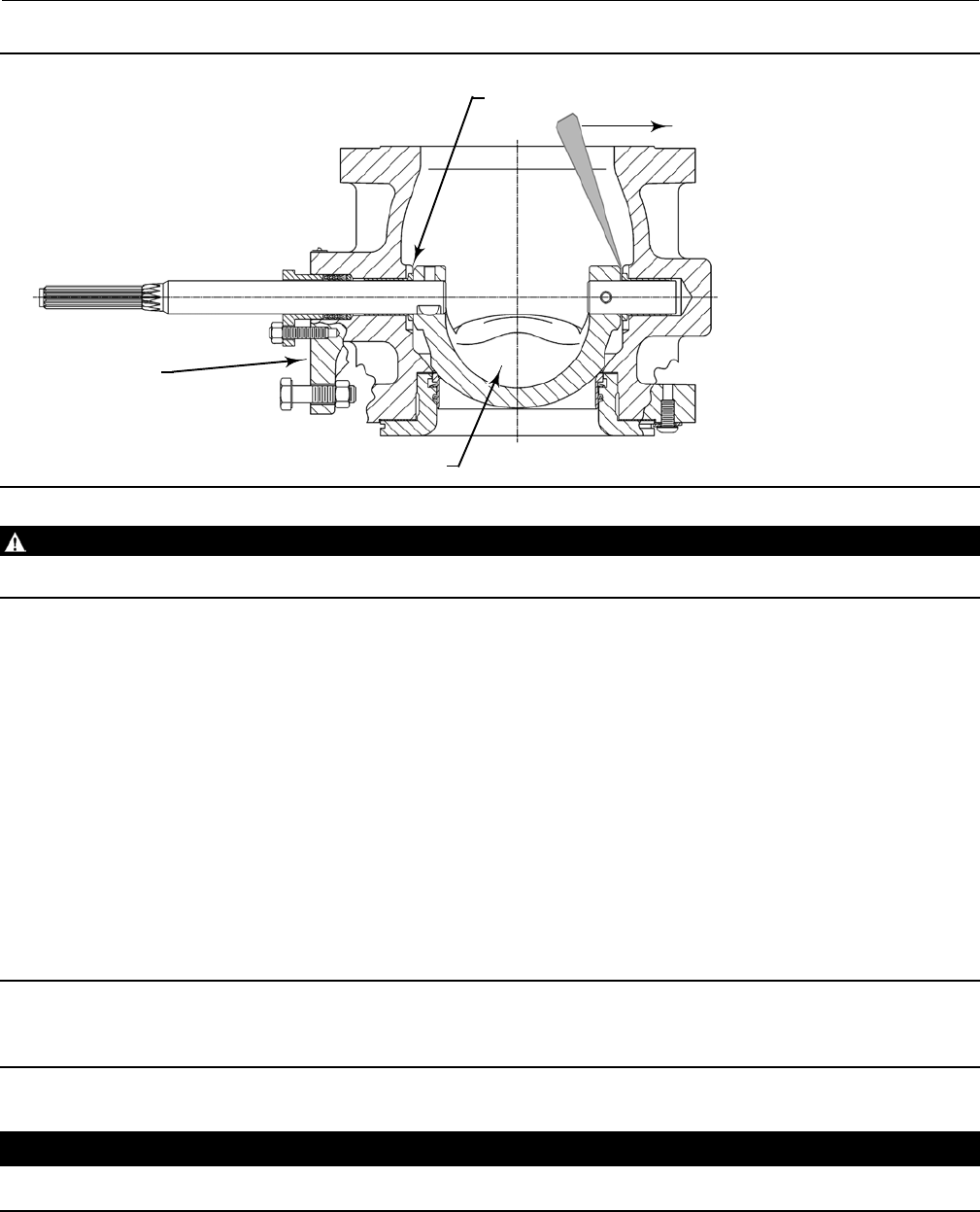
Figure 6. Typical Vee-Ball Valve Showing Pry Bar
BALL
ACTUATOR SIDE
OF VALVE
58B2296-B
E0739
THRUST AND BEARING SURFACE
PRY IN THIS DIRECTION
WARNING
Perform the steps in the WARNING at the beginning of the Maintenance section of this manual.
1. Remove line bolting, remove the control valve from the pipeline, and place the valve on a flat surface with the seal
protector ring facing up. Carefully rotate the ball to the open position.
2. Remove protector ring screws and washers (keys 21 and 22). Carefully remove the seal protector ring and gasket
(keys 3 and 15). (For flow ring constructions, go to step 4.)
a. For a Fisher TCM seal, remove the seal (key 11) from the valve body. For NPS 1, 1-1/2, and 2 valves, also remove
the backup ring (key 14, figure 8) from the valve body.
b. For a flat metal seal, remove the spring seal, seal, and shims (keys 13, 11, and 12). (Note: It may be necessary to
re-use some of the original shims when reassembling the flat metal seal.)
c. For an HD metal seal or a high temperature HD metal seal, once the protector ring has been removed from the
valve, push the metal seal (key 11) out of the seal protector ring (key 3). Remove the wave spring (key 13), and
on the HD metal seal, the radial seal (key 37).
Note
The high temperature HD metal seal also has a piston ring (key 133) that will need to be removed. It will be in two pieces for the
NPS 1, 1-1/2 and 2 valves, and one piece with a break in it for the NPS 3 through 12 valves.
CAUTION
Exercise care to avoid damaging components in the following procedure.
Instruction Manual
D101554X012
Vee-Ball Valves
January 2015
12
DIt might be necessary to remove the HD metal seal by carefully tapping it with a soft punch and hammer.
Take care not to damage the seal protector ring.
DNPS 3 through 12 valves, if the seal is difficult to push out, it is recommended that a seal removal plate be
used to press the HD metal seal out of the seal protector ring. Refer to figure 12 for dimensions of the seal
removal plate.
DNPS 10 and 12 valves with an attenuator only: Remove the retaining ring (key 41) in the seal protector ring.
This retaining ring is an octagonal-shaped support wire. To remove the retaining ring, find one of the free
ends of the ring. Use a screwdriver or similar tool to pry inward and upward until the ring is removed.
3. Inspect the gasket and sealing surfaces on the valve body (key 1 or 1A), the seal protector ring (key 3), Vee-ball (key
2), and the retaining ring (key 41 for NPS 10 and 12 valves with an attenuator only). Be sure the sealing surfaces are
not damaged.
4. If replacement of the ball, shafts (keys 6 or 9), or bearings (key 10) is needed, proceed to the Bearing and Ball
Maintenance procedure. If only the seal is to be replaced, proceed to the Assembly steps below.
Assembly
Refer to figures 8, 9, and 10 for key number locations during seal installation. Valve key number locations are shown in
figures 24, 25, and 26.
1. Thoroughly clean all parts that are to be re-used and obtain replacement parts. Be sure that all sealing surfaces are
in good condition without scratches or wear. If the valve has been installed between line flanges and the flange
studs and nuts have been tightened, always replace the gasket (key 15) with a new gasket.
2. To help ensure correct side-to-side centering of the ball (key 2) on the seal (key 11), make sure the ball is closed
while you install the seal or flow ring and seal protector ring. Insert a screwdriver, pry bar, or similar tool between
thelowerearoftheballandthevalvebody(seefigure6).
3. Usetheprytomovetheballtightlyagainstthebearingontheactuatorsideofthevalve.Becareful,excessiveforce
may damage the ball. Keep the ball in that position until you have completed seal or flow ring installation. Check
the ball's position periodically, and re-center if necessary, during lever assembly and packing adjustments.
WARNING
The Vee-Ball closes with a shearing, cutting motion, which could result in personal injury. To avoid injury or property
damage, keep hands, tools, and other objects away from the Vee-Ball while stroking the valve.
4. Install the seal.
CAUTION
Due to the Vee-ball shape, take care to never completely rotate either the front skirted edge or the circular back edge of the
ball out of the ball seal as the seal could be damaged.
Instruction Manual
D101554X012
Vee-Ball Valves
January 2015
13
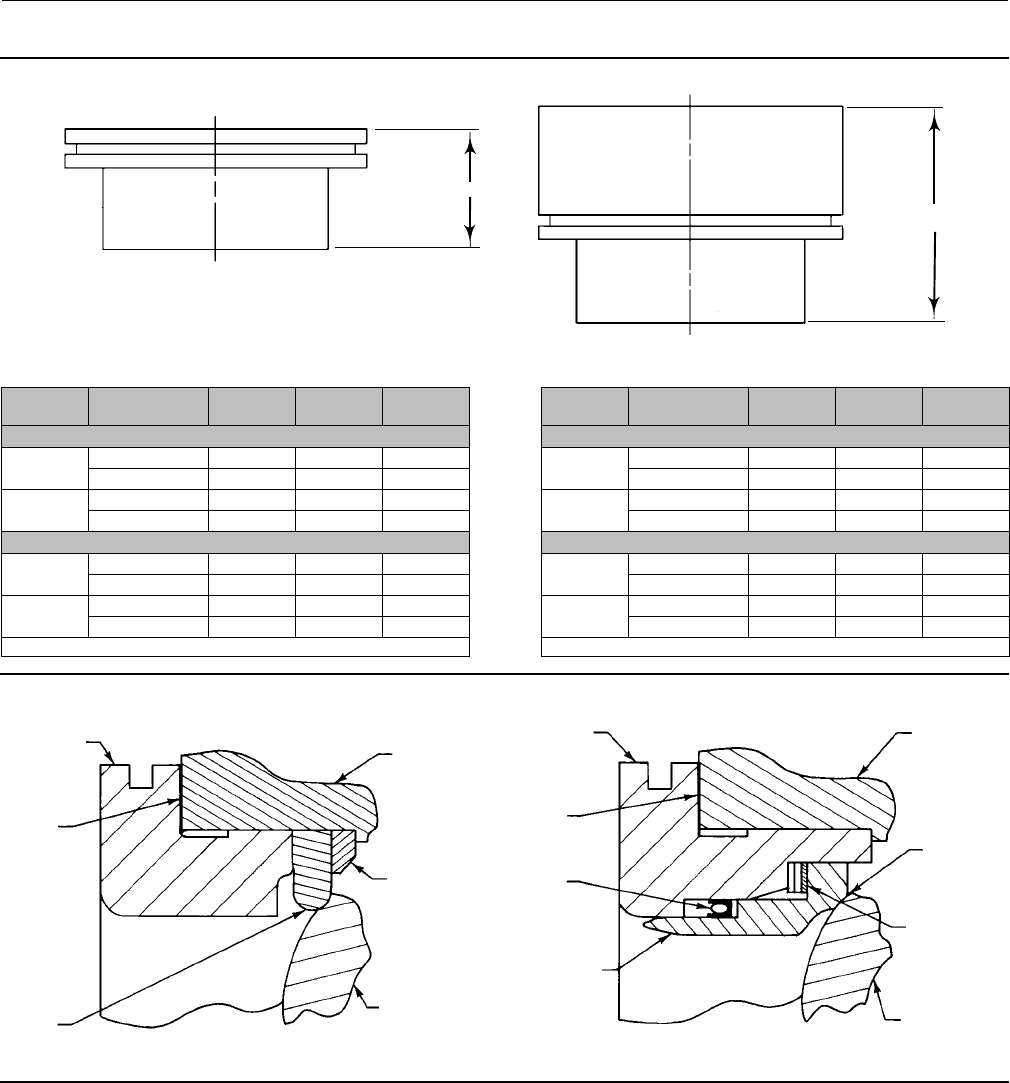
Figure 7. NPS 1 and 1-1/2 Seal Protector Ring Measurements
CL150 ASME B16.10 (SHORT) FACE-TO-FACE VALVE
D
A6960
ANSI/ISA S75.08.02 FACE-TO-FACE VALVE
D
A6959
Valve Size,
NPS Construction(1) TCM Seal
“D”
HD Seal
“D”
Flow Ring
“D”
mm
1New 37.6 44.7 39.6
Old 25.1 33.0 26.9
1-1/2 New 39.1 44.5 40.9
Old 27.4 32.8 29.2
Inches
1New 1.48 1.76 1.56
Old 0.99 1.30 1.06
1-1/2 New 1.54 1.75 1.61
Old 1.08 1.29 1.15
1. See the Note on page 14 of this Instruction Manual.
Valve Size,
NPS Construction(1) TCM Seal
“D”
HD Seal
“D”
Flow Ring
“D”
mm
1New 63.0 70.1 65.0
Old 50.5 58.4 52.3
1-1/2 New 89.9 95.3 91.7
Old 78.2 83.6 80.0
Inches
1New 2.48 2.76 2.56
Old 1.99 2.30 2.06
1-1/2 New 3.54 3.75 3.61
Old 3.08 3.29 3.15
1. See the Note on page 14 of this Instruction Manual.
Figure 8. Ball Seal Assembly for NPS 1, 1-1/2, and 2 Valves
SEAL PROTECTOR RING
(KEY 3)
GASKET
(KEY 15)
BALL SEAL
(KEY 11)
VALVE BODY
(KEY 1)
BACKUP RING
(KEY 14)
BALL (KEY 48)
SEAL PROTECTOR
RING (KEY 3)
GASKET
(KEY 15)
RADIAL SEAL
(KEY 37)
HD METAL BALL
SEAL (KEY 11)
APPLY
DRY FILM
LUBRICANT
WAVE SPRING
(KEY 13)
BALL (KEY 48)
VALVE BODY
(KEY 1)
Fisher TCM Plus BALL SEAL HD METAL BALL SEAL
A6032-2
Instruction Manual
D101554X012
Vee-Ball Valves
January 2015
14
Figure 9. Ball Seal Assembly for NPS 3 through 12 Valves
GASKET
(KEY 15)
SEAL PROTECTOR
RING (KEY 3)
VALVE BODY
(KEY 1A)
SEAL
(KEY 11)
BALL
(KEY 2)
GASKET
(KEY 15)
SEAL PROTECTOR
RING (KEY 3)
SHIMS
(KEY 12)
SPRING SEAL
(KEY 13)
FLAT METAL
SEAL (KEY 11)
APPLY DRY FILM
LUBRICANT
WAVE SPRING
(KEY 13)
RADIAL SEAL
(KEY 37)
HD METAL BALL
SEAL (KEY 11)
RETAINING RING
WITH ATTENUATOR
ONLY (KEY 41)
GASKET
(KEY 15)
GASKET
(KEY 15)
SEAL PROTECTOR
RING (KEY 3) SEAL PROTECTOR
RING (KEY 3)
APPLY DRY
FILM
LUBRICANT
WAVE SPRING
(KEY 13)
RADIAL SEAL
(KEY 37)
HD METAL
BALL
SEAL (KEY 11)
NPS 3 THROUGH 12
FISHER TCM PLUS SEAL
NPS 3 THROUGH 12
FLAT METAL BALL SEAL
NPS 3 THROUGH 8
HDMETALBALLSEAL NPS 10 AND 12
HD METAL BALL SEAL
41B0742-E
B2338-3
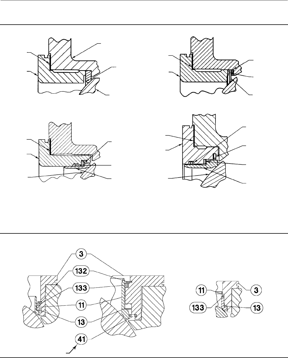
Figure 10. High Temperature HD Metal Seal Details
SEAL PROTECTOR RING
SEAL PROTECTOR RING
RETAINING RING
PISTON RING
PISTON RING
HD METAL SEAL
HD METAL SEAL
WAVE SPRING
WAVE SPRING
USE ONLY WHEN
ATTENUATOR IS USED
NPS 3 THROUGH 8
HD METAL BALL SEAL
NPS 10 AND 12
HD METAL BALL SEAL
NPS 1, 1-1/2 AND 2
HDMETALBALLSEAL
28B9882-A
E0261
Instruction Manual
D101554X012
Vee-Ball Valves
January 2015
15
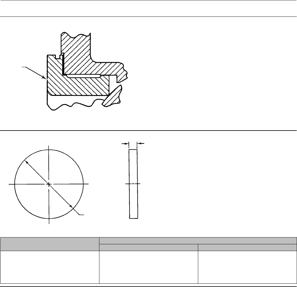
Figure 11. Seal Protector Ring
SEAL
PROTECTOR
RING (KEY 3)
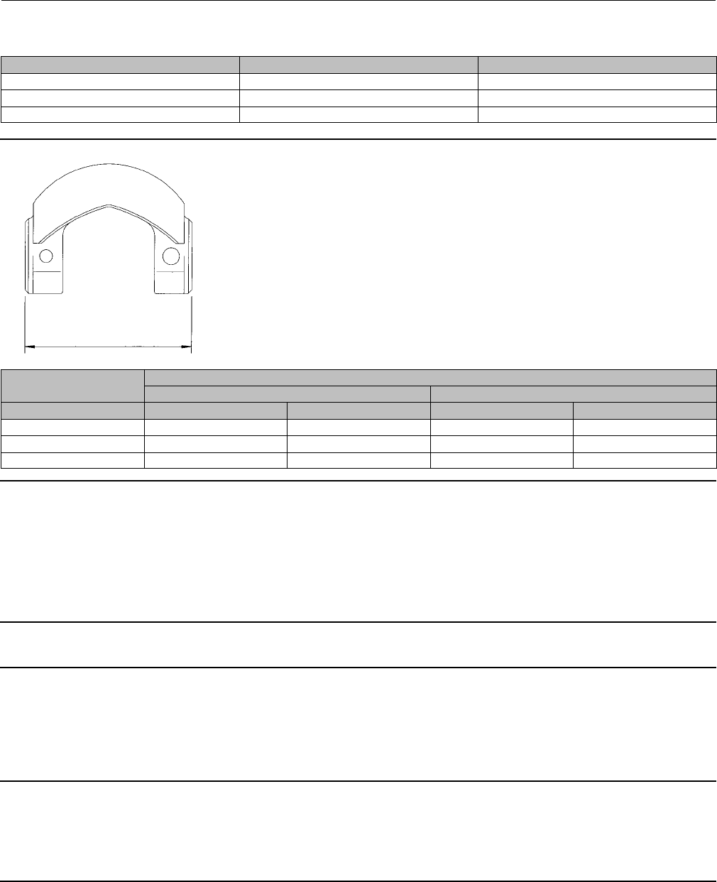
Figure 12. HD Seal Removal Plate Dimensions
A5544
A
6.4 mm
(0.250 INCHES)
MINIMUM
VALVE SIZE,
NPS
DIMENSION A
Minimum-Maximum, mm Minimum-Maximum, Inches
3
4
6
8
10
12
75.9-76.2
95.0-95.3
126.7-127.0
158.5-158.8
212.5-212.7
263.3-263.5
2.990-3.000
3.740-3.750
4.990-5.000
6.240-6.250
8.365-8.375
10.365-10.375
Installing Fisher TCM Plus or Extra ball seals:
a. NPS1,1-1/2,and2valves:Install the backup ring (key 14). Install the Fisher TCM seal (key 11) into the valve
body. Refer to figure 7.
DInstall the gasket (key 15) on the valve body.
DInstall the seal protector ring (key 3) into the valve body. Now go to step 5 in this procedure.
b. NPS 3 through 12 valves: Install the Fisher TCM seal (key 11) into the valve body.
DInstall the gasket (key 15) on the valve body.

Instruction Manual
D101554X012
Vee-Ball Valves
January 2015
16
DInstall the seal protector ring (key 3) into the valve body. Now go to step 5 in this procedure.
Installing flat metal seals:
a. Install 12 shims in the valve and install the flat metal seal on top of the shims.
b. Install the spring seal (key 13) on the flat metal seal (key 11) with the convex side of the spring seal facing the
ball.
c. Install the seal protector ring, and install the protector ring screws and washers (keys 21 and 22). Tighten the
screws.
d. Add or remove shims under the ball seal as necessary to obtain zero ball seal deflection as accurately as possible.
Note
Zero ball seal deflection for a flat metal seal is the point at which the addition of one 0.13 mm (0.005 inch) thick shim causes
contact between the ball and ball seal to be broken. Hold the parts tightly together when determining zero deflection, or improper
zero deflection might result.
e. After zero deflection is reached, remove the seal protector ring, spring seal, seal and 4 shims. Final assembly of
the control valve should not exceed a maximum of 9 shims for zero deflection. If more than 9 shims are required,
contact your Emerson Process Management sales office.
f. Install the gasket (key 15) on the valve body.
g. Install the seal protector ring (key 3) into the valve body. Now go to step 5 in this procedure.
Installing HD metal seals:
Note
The older and newer designs of the NPS 1 and 1-1/2 seal protector ring are functionally the same, but are different lengths and not
interchangeable. All NPS 1 and 1-1/2 sizes of V150 and V300 valves are the newer design. The change in seal protector ring length
occurred in the 1992/1993 timeframe and affects NPS 1 and 1-1/2 V200 valves only. To determine whether you have the older or
newer design, measure the length of the seal protector ring (key 3, figure 26) from its pipeline flange mating surface to its
opposite end. Compare your measurement to those listed in figure 7.
a. For NPS 1 and 1-1/2 valves: The older and newer designs of the NPS 1 and 1-1/2 seal protector rings are
functionally the same, but are different lengths and not interchangeable. Refer to figure 7 for protector ring
dimensions.
DInstall the wave spring (key 13) onto the ball seal.
DLubricate and install the radial seal (key 37) onto the ball seal (key 11). Make sure the open side of the radial
seal faces away from the ball.
DPush the ball seal assembly into the seal protector ring (key 3).
DGo to step 5 in this procedure.

Instruction Manual
D101554X012
Vee-Ball Valves
January 2015
17
b. For all NPS 3 through 8 valves and NPS 10 and 12 valves without attenuator:
DLubricate and install the radial seal (key 37) into the appropriate groove in the seal protector ring making
suretheopensideoftheradialsealfacesawayfromtheball.
DInstall the wave spring (key 13) into the seal protector ring (key 3).
DInstall the HD metal seal (key 11) into the seal protector ring (key 3), past the radial seal. While pushing it
past the radial seal, make sure the HD metal seal is level. Go to step 5 in this procedure.
c. For NPS 10 and 12 valves with attenuator:
DLubricate the radial seal with lithium grease and install the radial seal (key 37) into the appropriate groove
in the seal protector ring making sure the open side of the radial seal faces away from the ball.
DInstall the wave spring (key 13) into the seal protector ring (key 3).
DTo install the retaining ring (key 41), find one of the free ends of the ring. Insert the free end into the groove
in the seal protector ring. Work around the ring, pressing it into the groove until the ring is completely in its
groove.
DInstall the HD metal seal (key 11) into the seal protector ring (key 3), past the radial seal. While pushing it
past the radial seal, make sure the HD metal seal is level.
DThe HD metal seal uses a retaining ring (key 41) for NPS 10 and 12 valves only. This retaining ring is an
octagonal-shaped support wire. Go to step 5 in this procedure.
Installing high temperature HD metal seals:
a. For NPS 1, 1-1/2 and 2 valves: The older and newer designs of the NPS 1 and 1-1/2 seal protector rings are
functionally the same, but are different lengths and not interchangeable. All part numbers in this manual are for
the newer design. Refer to figure 7 for ring dimensions.
DPlace the wave spring (key 13) on top of the HD metal seal (key 11).
DBreak the piston ring (key 133) into two approximately equal pieces either by placing the ring over a pencil
or similar object and applying pressure down-wards ontheringuntiltheringsnaps.Besuretomatchthe
broken ends together as you install it on the HD metal seal (key 11).
DLay the HD metal seal (key 11) down on a flat surface and push the seal protector ring (key 3) into place.
Make sure the seal is level. Go to step 5 in this procedure.
b. For NPS 3 through 8 valves:
DPlace the piston ring (key 133) and retaining ring (key 132) into the appropriate groove in the seal protector
ring (key 3). The piston ring has one break in it; do not break it further.
DInstall the wave spring (key 13) into the seal protector ring (key 3).
DLay the HD metal seal (key 11) down on a flat surface and push the seal protector ring (key 3) past the
piston ring (key 133) and into place. Make sure the seal is level. Go to step 5 in this procedure.
c. For NPS 10 and 12 valves:
DPlace the piston ring (key 133) and retaining ring (key 132) into the appropriate groove in the seal protector
ring (key 3). The piston ring has one break in it; do not break it further.
Instruction Manual
D101554X012
Vee-Ball Valves
January 2015
18
DInstall the wave spring (key 13) into the seal protector ring (key 3).
DIf the valve has an attenuator, install the retaining ring (key 41). The octagonal shaped support wire ring has
twofreeends.Placeoneofthefreeendsintothegrooveinthesealprotectorring.Thenstartingatthe
inserted end, press the rest of the ring into the groove completely.
DLay the HD metal seal (key 11) down on a flat surface and push the seal protector ring (key 3) past the
piston ring (key 133) and into place. Make sure the seal is level. Go to step 5 in this procedure.
5. Install a replacement gasket (key 15) on the valve body (key 1 or 1A). Install the HD metal ball seal/seal protector
ring assembly into the valve body (key 1 or 1A).
6. Install washers (or clips), and screws that clamp the seal protector ring to the valve body [keys 3, 21, and 22; the
V200 valve uses clips (key 22) in place of washers].
7. If necessary, refer to the Packing Maintenance procedures to install the packing. Install the actuator using the
Actuator Mounting procedures or to the appropriate actuator instruction manual.
HDMetalSealLubrication
To assist with break-in of the HD metal seals, it is recommended that the ball and seal be lubricated with dry film
lubricant or equivalent moly disulfide.
Bearing and Ball Maintenance
WARNING
Before performing the steps in this section, observe the WARNING at the beginning of the Maintenance section on page 7.
NPS3through12Valves
Procedures for disassembly and assembly of the bearings and ball cannot be accomplished until the ball seal and valve
packing are removed from the valve.
Refer to the Replacing Packing procedures to remove the actuator, and to remove the packing flange and packing
follower from the valve. When the packing disassembly steps are complete, return to this section.
Refer to the Replacing the Ball Seal procedures to remove the ball seal from the valve.
Table 3. Continuous Threaded Rod
Valve Size, NPS Threaded Rod Thread Size ThreadDepthinFollowerShaft
30.25-20 0.5
40.25-20 0.5
60.25-20 0.5
80.3125-18 0.62
10 0.3125-18 0.62
12 0.3125-18 0.94
Disassembly
WARNING
When the actuator is removed from the valve, the ball/shaft assembly may suddenly rotate, with a shearing, cutting
motion, which could result in personal injury. To avoid injury, carefully rotate the ball to a stable position at the bottom of
the valve body cavity. Make sure the ball will not rotate.
Instruction Manual
D101554X012
Vee-Ball Valves
January 2015
19
Key numbers in this procedure are shown in figures 24, 25, and 26, unless otherwise indicated.
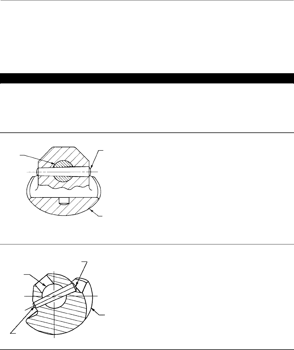
1. A taper key (key 4, figures 14, 24, 25 and 31) is used to connect the ball and drive shaft in NPS 3 through 12 valves.
2. Carefully rotate the ball to the open position after the actuator is disconnected. Make sure the ball will not rotate
(see warning above). Provide support for the ball during the following disassembly.
3. Working from the small end of the groove pin (key 7), use a pin punch to drive the groove pin out of the ball ear and
follower shaft.
For tack welded taper keys, driving the taper key out of the ball ear will shear the tack welding.
4. Locate the small end of the taper key (key 4, see figures 14, 24, 25 and 31). Using a pin punch on the smaller end of
the taper key, drive it out of the ball (key 2) and drive shaft (key 6). Note: driving the taper key in the wrong
direction will tighten it.
5. Pullthedriveshaft(key6)outoftheactuatorsideofthevalvebody.
CAUTION
Exercise care to avoid damaging components in the following procedure.
6. Theballwillbefreetomovewhenbothshaftsareremoved.Makesurethesealingsurfaceoftheballisnot
damaged while removing the follower shaft.
a. Unscrew the pipe plug (key 25) if one is installed. Use a punch to drive the follower shaft (key 9) into the center of
the ball.
b. If a pipe plug is not installed, use a piece of continuous threaded rod as a removal rod when moving the follower
shaft (key 9) into the center of the ball. Refer to the table 3 for a description of the size threaded rod needed. The
length of the rod should allow easy working room from the valve body.
7. Carefully remove the follower shaft and ball (key 2) from the valve body.
For NPS 4 valves with attenuator, remove the ball/attenuator through the inlet of the valve. Taking hold of the follower
shaft ear on the ball/attenuator, you must position the scalloped edge of the attenuator against the valve bore
opening and then pivot, or roll, the ball/attenuator out of the valve body (see figure 18).
For NPS 6, 8, 10, and 12 valves with attenuator, remove the ball/attenuator through the outlet of the valve by carefully
turning and manipulating the ball. The NPS 6, 8, 10, or 12 ball/attenuator will not come straight out of the valve body.
8. Remove the bearings (key 10) by hand. If the bearings are tight in the valve body, then pull or drive them out with a
slight pressure.
DTo remove the follower shaft bearings, use a blind-hole bearing puller. If you do not have such a tool, you can
machine the bearing out.
9. Thoroughly clean surfaces of all parts that are to be re-used or obtain replacement parts.
Assembly
1. Inspect all sealing surfaces to ensure they are in good condition and without scratches or wear.
2. Install the replacement bearings (key 10) by hand. The bearing flanged end should touch the valve body.
3. Installing the Vee-Ball: Ensure the ball part number matches up with the appropriate seal type as shown in the key 2
ball table in the parts list section of this instruction manual.
WARNING
The ball might be damaged if it is allowed to fall into the valve body. To avoid personal injury or damage to the sealing
surfaces, support the ball to prevent it from falling into or out of the valve body cavity.
Instruction Manual
D101554X012
Vee-Ball Valves
January 2015
20
Note
For ease of assembly, the follower shaft (key 9) should be inserted into the ball before installing the ball in the following
applications:
DNPS 3 valve without ball/attenuator
DNPS 4 through 12 valves with ball/attenuator.
Carefully install the ball into the valve body cavity.
DFor Vee-Ball with attenuator (NPS 4 through 12 valves), carefully install the ball into the valve body cavity. For NPS 4
valves, install the ball/attenuator through the inlet of the valve. For NPS 6, 8, 10, and 12 valves, install the
ball/attenuator through the outlet of the valve. Taking hold of the follower shaft ear on the ball/attenuator, you
must position the scalloped edge of the attenuator against the valve bore opening and then carefully pivot, or roll,
the ball/attenuator into the valve body (see figure 18).
After you have installed the ball (key 2) into the valve body assembly, firmly support the ball while installing the shafts.
4. Installing the follower shaft (key 9):
DFor NPS 3 valves: The follower shaft (key 9) should already have been inserted into the ballbeforetheballwasput
into the valve body. Insert the follower shaft (key 9) into the valve body bearing (key 10).
DFor NPS 4 and larger valves: Insert the follower shaft (key 9) through the ball, and into the valve body bearing (key
10).
DFor NPS 4 through 12 valves with ball/attenuator: The follower shaft (key 9) should already have been inserted into
the ball/attenuator before the ball was put into the valve body. Insert the follower shaft (key 9) into the valve body
bearing (key 10).
Then for all sizes, align the hole in the follower shaft with the holes in the ball. Insert the small end of the groove pin
(key 7) into the hole in the ball and into the follower shaft. The pin will hold the parts in place while the drive shaft (key
6) is being installed.
Table 4. Taper Key Minimum Depth
Valve Size, NPS Minimum Depth To Drive Taper Key After Initial Solid Contact, mm (Inches)
3, 4, 6
8, 10, 12
4.8 (0.188)
5.6 (0.219)
Table 5. Taper Key Maximum Depth
Valve Size, NPS Maximum Depth To Drive Taper Key After Initial Solid Contact, mm (Inches)
3, 4
6
8, 10
12
7.1 (0.281)
7.9 (0.312)
9.5 (0.375)
10.3 (0.406)
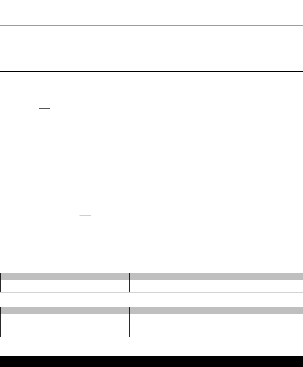
5. Installing the Drive Shaft:
CAUTION
The drive shaft must be used with the correct Vee-Ball. Refer to the tag (see figure 13) attached to the Vee-Ball and to the
drive shaft.
Instruction Manual
D101554X012
Vee-Ball Valves
January 2015
21
Failure to use the correct Vee-Ball/ shaft combination may result in the ball not being in the position indicated by the slash
mark on the end of the shaft. If the ball is not properly aligned with the slash mark, the valve will not function correctly and
seal damage may result.
Figure 13. Informational Tag
GE11636-A FOR STANDARD RIGHT/LEFT HAND BALL GE11637-A FOR OPTIONAL LEFT HAND BALL
CAUTION
Make sure the drive shaft is free of oil or grease, otherwise the taper pin or taper key will not seat properly. Failure to
properlysetthetaperpinortaperkeycouldresultinitcoming loose while in service. Loosening of the taper key in service
could result in improper valve function and equipment damage.
a. Insert the drive shaft into the valve body bearing (key 10), and into the ball ear. Align the hole in the drive shaft
with the holes in the ball.
b. Insert the taper key into the ball and drive shaft as shown in figure 14.
DInstalling the Taper Key
Current standard construction materials for all NPS 3 through 12 valves require the taper key (key 4, figure 14) to be
tack welded in place after properly seating, using the following procedure. Use standard welding preparations when
preparing parts for reassembly.
CAUTION
Make sure the drive shaft (key 6) is free of oil or grease, otherwise the taper key will not seat properly. Failure to properly
set the taper pin or taper key could result in it coming loose while in service. Loosening of the taper key in service could
result in improper valve function and equipment damage.
Instruction Manual
D101554X012
Vee-Ball Valves
January 2015
22
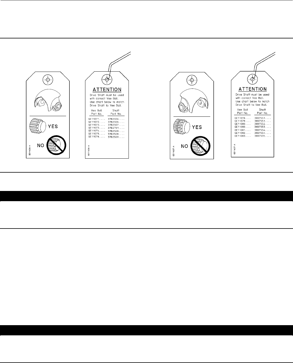
Figure 14. Taper Key Installation
MAXIMUM ENGAGEMENT OF TAPER KEY
31B0727-E
A6035-1
BALL
(KEY 2)
TACK WELD
TAPER KEY
(KEY 4)
DRIVE SHAFT
(KEY 6)
TACK WELD
TAPER KEY
(KEY 4)
MINIMUM ENGAGEMENT OF TAPER KEY
6. Install the drive shaft (key 6) into the valve body through the ball and into the lower bearing.
7. Insert the taper key (key 4) into ball and drive shaft (keys 2 and 6) as shown in figure 14. The taper key inserts, with
theflatsideofthekey,facingthedriveshaft(key6).
8. Using a flat end punch, drive the groove pin (key 7) into the ball ear and follower shaft until it is flat with the ball ear
surface. Stake both ends of the pin hole with a centerpunchtoensurethegroovepindoesnotcomeout.
9. Using a flat end punch, drive the taper key (key 4) into the ball ear and drive shaft (key 6) until solid, heavy contact is
obtained between the key and shaft.
10. Measure the position of the taper key head.
11. Drive the taper key in further using the minimum distance shown in table 4.
12. Inspect the ball/shaft taper key connection to verify that the taper key spans the entire shaft flat width. If not, the
taper key must be driven in further until this condition is satisfied. However, do not exceed the maximum depths
shownintable5.
Note
All valve taper keys are tack welded, except titanium.
13. When the above conditions are met, tack weld the taper key (key 4) to the ball ear on the head end of the key (see
figures 24 and 25). Use a:
D1/8inchdiameterweldonNPS3through6valves,
D3/16 inch diameter weld on NPS 8 through 10 valves, and
D1/4inchdiameterweldonNPS12valves.
Instruction Manual
D101554X012
Vee-Ball Valves
January 2015
23
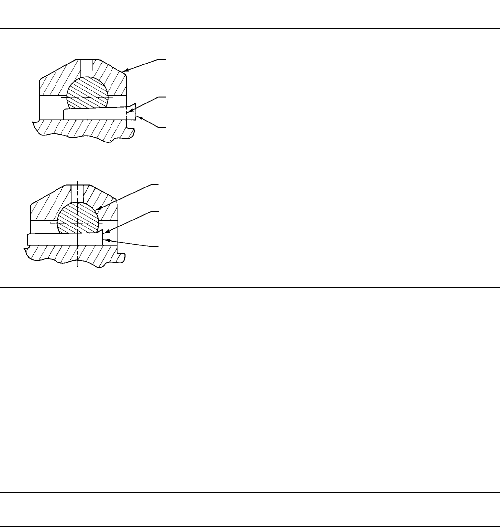
Figure 15. Typical Metal Micro-Notch Ball and Drive Shaft
MICRO-NOTCH V-NOTCH BALL
DRIVE SHAFT
W6256
For all constructions: Refer to Replacing the Ball Seal, Packing Maintenance, and other procedures as necessary to
complete the assembly of the valve.
NPS 1 through 2
Procedures for disassembly and assembly of the bearings and ball cannot be accomplished until the ball seal and valve
packing are removed from the valve.
Refer to the Replacing Packing procedures to remove the actuator, and to remove the packing flange and packing
follower from the valve. When the packing disassembly steps are complete, return to this section.
Refer to the Replacing the Ball Seal procedures to remove the ball seal from the valve.
Disassembly
WARNING
When the actuator is removed from the valve, the ball/shaft assembly may suddenly rotate, with a shearing, cutting
motion, which could result in personal injury. To avoid injury, carefully rotate the ball to a stable position at the bottom of
the valve body cavity. Make sure the ball will not rotate.
Key numbers in this procedure are shown in figures 24, 25, and 26, unless otherwise indicated.
1. A taper pin (key 4, figure 20) is used in the NPS 1, 1-1/2, and 2 valves, and in the NPS 1 Metal Micro-Notch valve
(figure 21).
2. Ceramic Micro Notch ball constructions: Ascrew(key 4, figure 22) is used to attach the ball to the drive shaft.
CAUTION
Exercise care to avoid damaging components in the following procedure.
a. The parts are held together with a screw and an adhesive. Remove the screw (key 4) and separate the drive shaft
from the ball. In some cases, a small amount of heat can be applied to help loosen the adhesive. However,
excessive heat may damage other valve component parts.
b. Oncetheshaftshavebeenremovedfromthevalvebody,theballmayfall.Toavoidpersonalinjuryordamageto
the sealing surfaces, provide support for the ball to prevent it from falling as the shaft(s) are being removed.
Instruction Manual
D101554X012
Vee-Ball Valves
January 2015
24
Table 6. Continuous Threaded Rod
Valve Size, NPS Threaded Rod Thread Size ThreadDepthinFollowerShaft
11/4-20 0.5
1.5 1/4-20 0.5
21/4-20 0.5
Figure 16. Dimensions of Ball in Ball / Shaft Assembly
A
VALVE SIZE A
NEW - WITHOUT THRUST WASHER OLD - WITH THRUST WASHER
NPS mm Inches mm Inches
132.9 1.29 31.8 1.25
1.5 48.6 1.91 47.7 1.88
264.5 2.54 63.4 2.50
3. Carefully rotate the ball to the open position after the actuator is disconnected. Make sure the ball will not rotate
(see warning above). Provide support for the ball during the following disassembly.
4. Unscrew the pipe plug (key 25). (The pipe plug is optional and may not be available.)
5. Working from the small end of the groove pin (key 7), use a pin punch to drive the groove pin out of the ball ear and
follower shaft.
Note
All NPS 1 Micro-Notch constructions use a one piece shaft. They do not have a follower shaft.
6. Locate the small end of the taper key (key 4, figure 14). Using a pin punch on the smaller end of the taper key, drive
it out of the ball (key 2) and drive shaft (key 6). Note: driving the taper key in the wrong direction will tighten it.
7. Pullthedriveshaft(key6)outoftheactuatorsideofthevalvebody.
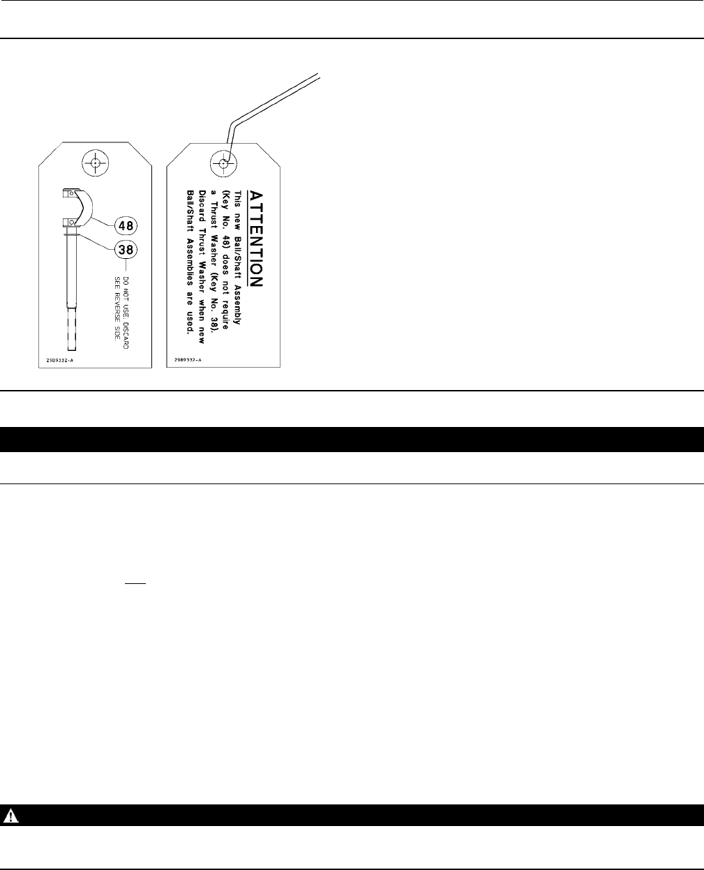
Note
The new ball/shaft assembly (key 48) does not require a thrust washer (key 38) in valves ordered after November 01, 2001.
Discard the thrust washer in valves ordered prior to this date when new ball/shaft assemblies are used as spare parts.
Figure 17 shows the informational tag that is attached with the new ball/shaft assembly when shipped as a spare part. Refer to
figure 16 for dimensions of the ball in the ball/shaft assembly.
Instruction Manual
D101554X012
Vee-Ball Valves
January 2015
25
Figure 17. Informational Tag
29B9332
CAUTION
Exercise care to avoid damaging components in the following procedure.
8. Make sure the sealing surface of the ball is not damaged while removing the follower shaft.
a. If a pipe plug (key 25) is installed, use a punch to drive the follower shaft (key 9) into the center of the ball.
b. If a pipe plug is not installed, use a piece of continuous threaded rod as a removal rod when moving the follower
shaft (key 9) into the center of the ball. Refer to the table 6 shown below for a description of the size threaded
rod needed. The length of the rod should allow easy working room from the valve body.
9. Remove the ball (key 2) by carefully removing the follower shaft and ball from the valve body.
10. Remove the bearings (key 10) by hand. If the bearings are tight in the valve body, then pull or drive them out with
a slight pressure.
11. Thoroughly clean surfaces of all parts that are to be re-used or obtain replacement parts.
Assembly
1. Inspect all sealing surfaces to ensure they are in good condition and without scratches or wear.
2. Install bearings (key 10) by hand. The bearing flanged end should touch the body.
3. Installing the ball (key 2):
WARNING
The Vee-Ball might be damaged if it is allowed to fall into the valve body. To avoid personal injury or damage to the sealing
surfaces, support the ball to prevent it from falling into or out of the valve body cavity.
Instruction Manual
D101554X012
Vee-Ball Valves
January 2015
26
Figure 18. Ball/Attenuator Installation and Removal Method
W6134
BALL/ATTENUATOR
Note
For ease of assembly, the follower shaft (key 9) should be inserted into the ball before installing the ball in an NPS 3 valve without
ball/attenuator
Carefully install the ball into the valve body cavity.
After you have installed the ball (key 2) into the valve body assembly, firmly support the ball while installing the shafts.
4. Installing the follower shaft (key 9):
DFor NPS 1 through 2 valves: The follower shaft (key 9) should already have been inserted into the ball before the ball
was put into the valve body. Insert the follower shaft (key 9) into the valve body bearing (key 10).
Note
All NPS 1 Micro-Notch constructions use a one piece shaft. They do not have a follower shaft.
5. Installing the Drive Shaft for Valves with Taper Pins
CAUTION
The drive shaft must be used with the correct Vee-Ball. Refer to the tag (see figure 13) attached to the Vee-Ball and to the
drive shaft.
Failure to use the correct Vee-Ball/ shaft combination may result in the ball not being in the position indicated by the slash
mark on the end of the shaft. If the ball is not properly aligned with the slash mark, the valve will not function correctly and
seal damage may result.
Instruction Manual
D101554X012
Vee-Ball Valves
January 2015
27
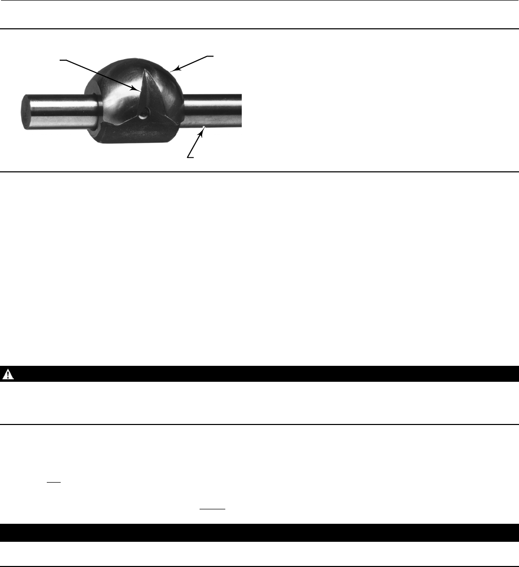
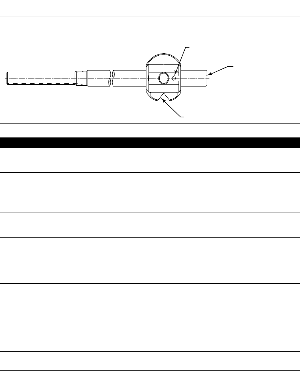
Figure 19. Location of Indicator Hole in Micro-Notch Vee-Balls
FOLLOWER END OF BALL
SHAFT/ASSEMBLY
29B9552-A
E0764
INDICATOR HOLE
NOTCH
CAUTION
Make sure the drive shaft is free of oil or grease, otherwise the taper pin will not seat properly. Failure to properly set the
taper pin or taper key could result in it coming loose while in service. Loosening of the taper key in service could result in
improper valve function and equipment damage.
6. Insert the drive shaft into the valve body bearing (key 10), and into the ball ear (or ball, for Micro-Notch
constructions).Aligntheholeinthedriveshaftwiththeholesintheball.
Note
There is an indicator hole drilled in all Micro-Notch balls. This indicator hole must be oriented closest to the follower end of the
ball/shaft assembly. See figure 19.
7. Insert the taper pin into the ball and drive shaft as shown in figures 20 and 21. The small end of the taper pin must
be inserted into the larger hole side of the ball ear (or ball, for Micro-Notch constructions), and into the large hole
side of the drive shaft.
Note
The taper pin will not fit correctly if inserted in the wrong direction through the ball ear (or ball, for Micro-Notch constructions) or
throughthedriveshaft.Makesurethedriveshaftandballear(orball,forMicro-Notchconstructions)areinthecorrectorientation
for installing the pin.
DInstalling Taper Pins in NPS 1, 1-1/2, and 2 Valves
Note
For NPS 1, 1-1/2, and 2 valves, the taper pins (figure 20) do not require welding.
Instruction Manual
D101554X012
Vee-Ball Valves
January 2015
28
Using a flat-end punch, drive the taper pin into the ball ear (or ball, for Micro-Notch constructions) and drive shaft until
solid heavy contact is felt. Make sure the taper pin spans the width of the ball.
Using a flat end punch, drive the groove pin (key 7) into the ball and follower shaft until it is flat with the ball surface.
Installing the Drive Shaft in VTC Ceramic Vee-Ball Valves
CAUTION
The drive shaft must be used with the correct Vee-Ball. Refer to the tag (see figure 13) attached to the Vee-Ball and to the
drive shaft.
Failure to use the correct Vee-Ball/ shaft combination may result in the ball not being in the position indicated by the slash
mark on the end of the shaft. If the ball is not properly aligned with the slash mark, the valve will not function correctly and
seal damage may result.
Figure 20. Taper Pin Installation for Fisher V150, V200, and V300 NPS 1, 1-1/2, and 2 Valves
A6033-1
DRIVE SHAFT
(KEY 6) TAPER PIN
(KEY 4)
BALL
(KEY 2)
Figure 21. Taper Pin Installation for Fisher V150, V200, and V300 NPS 1 Valves with Micro-Notch Ball Construction
E0738
DRIVE SHAFT
(KEY 6)
WHEN FULLY SET, PIN
SHOULD BE FLUSH OR 0.06'
TAPER PIN
(KEY 4)
MICRO-NOTCH BALL
(KEY 2)
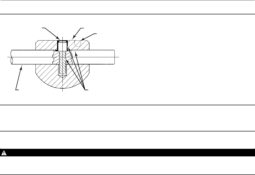
Valves with NPS 1 ceramic micro-notch balls use a screw with a threaded valve shaft to connect the ball to the shaft. An
adhesive is used to lock the screw in the valve shaft (keys 4 and 6, figure 22).
Instruction Manual
D101554X012
Vee-Ball Valves
January 2015
29
Figure 22. Screw Installation for Fisher V200, NPS 1 Valves with VTC Ceramic Micro-Notch Ball Construction
SCREW (KEY 4) BALL (KEY 2)
DRIVE SHAFT
(KEY 6)
LOCK COMPOUND
(KEY 49)
44B0241-B
A6961
INDICATOR HOLE
Note
There is an indicator hole drilled in all Micro-Notch balls. The orientation of this hole in the ceramic Vee-Ball is to the right of the
screw in the ball, and must be located closest to the follower end of the ball/shaft assembly. See figures 19 and 22.
WARNING
Avoid personal injury and property damage from ignition of process fluid caused by sparks from ceramic trim.
Do not use ceramic trim where the process fluid is unstable or if it is an explosive mixture (such as ether and air).
Within the valve body:
8. The threaded hole in the shaft, the screw and screw clearance hole in the ball must be free of oil and grease before
applying an activator.
9. Apply LoctiterDependrActivator 7387 to threaded hole, screw and ball clearance hole. Assemble the ball onto the
shaft while aligning threaded shaft hole within the ball clearance hole.
10. The flat on the shaft must be oriented so that the head of the cap screw seats on the flat.
11. Apply 5 drops of Loctite Depend 330 into the hole in the ball.
12. Thread the screw into the shaft tightening it to 9.2 NSm(81inSlbs) torque. Remove excess adhesive, Allow four
hours to cure fully before continuing with assembly.
For all constructions: Refer to Replacing the Ball Seal, Packing Maintenance, and other procedures as necessary to
complete the assembly of the valve.
Actuator Mounting
Use the appropriate actuator instruction manual, this section of this manual, and figure 23 of this manual when
mounting the actuator or changing actuator styles and positions.
1. To help ensure correct centering of the Vee-Ball (key 2)ontheseal(key11),besuretheballisclosedwhen
mounting the actuator (for applications other than Spring Return Fail-Open).

Instruction Manual
D101554X012
Vee-Ball Valves
January 2015
30
2. Clean the valve shaft and actuator lever splines to be sure the actuator lever will slide on easily. Only drive the lever
in if absolutely necessary.
3. Carefully wedge the ball solidly against the actuator-side bearing, using a screwdriver or similar tool inserted
between the lower ear of the ball and the valve body.Thiswillcentertheball.Seefigure6.
4. Keep the wedge in place while installing the lever, if necessary. Remove the wedge after you have clamped the
actuator lever on the valve shaft and have connected the lever to the actuator piston rod or diaphragm rod.
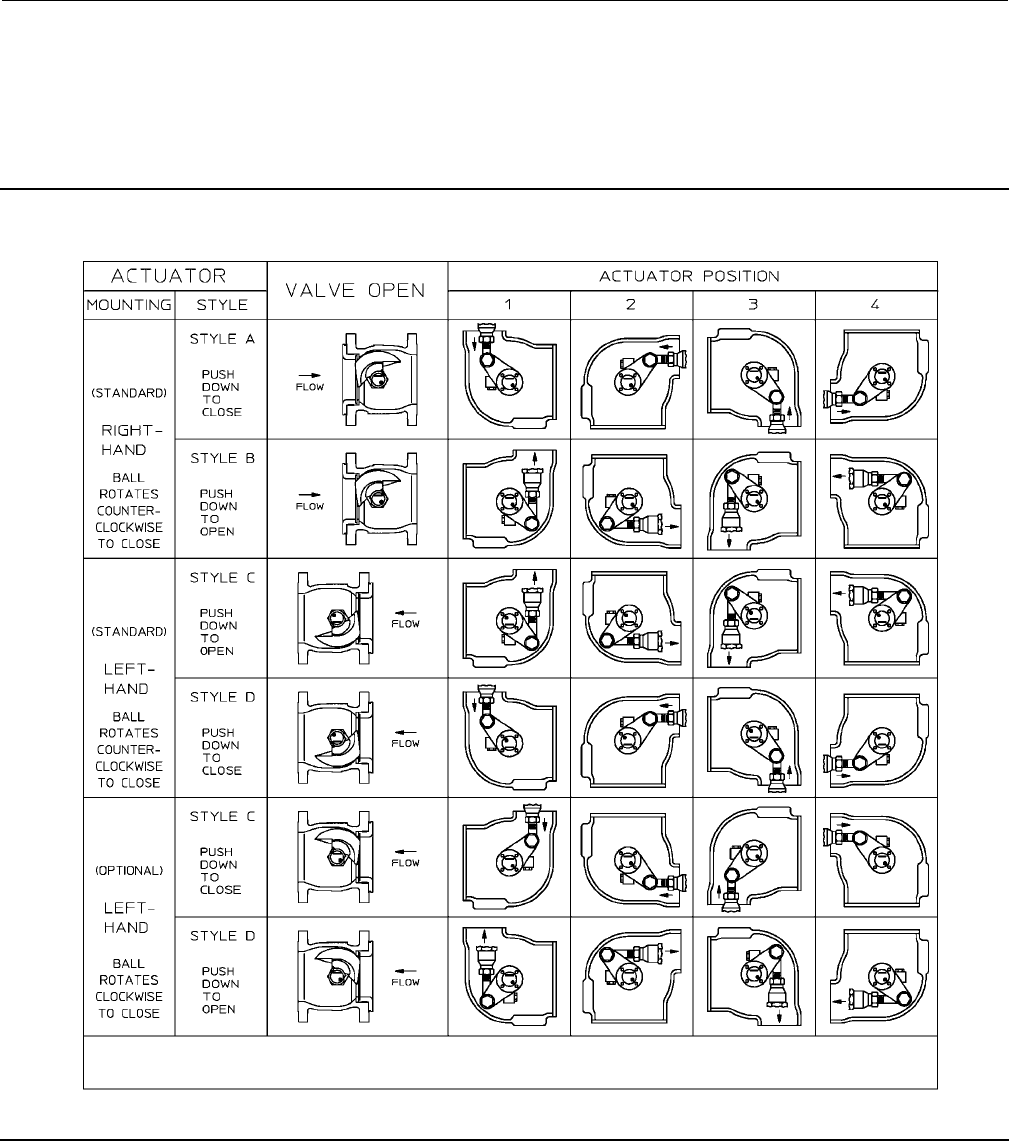
Determining Mounting Position
The actuator can be either right or left-hand mounted, with the actuator on the right or left side when viewed from
upstream (see figure 23).
The Series B Vee-Ball, NPS 4 through 12 with attenuator, and the NPS 1 micro-notch Vee-Ball have one V-notch. For
right-hand mounting (standard), the ball will be in the top of the valve body when the valve is open and the shaft is
horizontal.InthispositiontheballrotatesCCWtoClose.Forleft-handmounting(standard), the ball will be in the
bottom of the valve body when the valve is open and the shaft is horizontal. In this position the ball rotates CCW to
Close. An optional ball for left-hand mounting, which rotates into the top of the valve body when the shaft is
horizontal, is also available. In this position the ball rotates CW to Close.
TheNPS1through2hastwonotches,andcan be rotated in either direction.
Determining Closed Position
1. Thevalvemustberemovedfromthelinetocheckthepositionoftheball.
WARNING
The Vee-Ball closes with a shearing, cutting motion. To avoid personal injury, keep hands, tools, and other objects away
from the ball while stroking the valve.
2. Rotate the ball to the closed position.
3. Position the ball in the proper location
For Series B:
DWhen viewed from the valve body inlet, the ball is in the proper position when the flat spot on the top of the ball is
exactly in the center of the seal package.
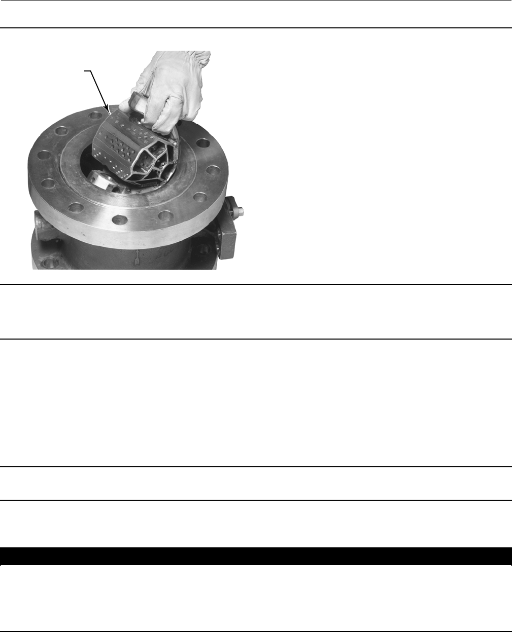
Make a copy of the centering template in figure 27 out of a suitable stiff material. Place the centering template in the
opening at the seal (See figure 27). Find the center of the template and make sure the spot on the ball is centered
directly below it.
For NPS 1, 1-1/2, and 2 valves with attenuators: Follow one of the procedures below:
DWhen viewed from the valve body inlet, the ball is in the proper position when both V-notches of the ball are
centered between the machined diameter of the ledge that supports the seal.
DIf the ball has a spot machined on the top, align that spot to the exact center of the seal cavity.
4. Adjust the actuator linkage as described in the appropriate actuator instruction manual until the ball is centered in
theclosedposition.Alineisstampedontheactuatorendofthedriveshaft(seefigure23)toindicatetheball
position.
Instruction Manual
D101554X012
Vee-Ball Valves
January 2015
31
Use the appropriate actuator instruction manual and figure 23 of this manual when mounting the actuator or
changing actuator styles and positions.
The Micro-Notch ball closed position is approximately 5 degrees closed from the first point of flow. This establishes the
zero degree position for the ball.
Figure 23. Index Marks for Actuator Lever Orientation for NPS 1 through 12 Valves with or without Attenuator
48B4773-C
NOTE:
1. ARROW ON LEVER INDICATES DIRECTION OF ACTUATOR THRUST TO CLOSE VALVE.
2. THE OPTIONAL LEFT-HAND ORIENTATION IS NOT AVAILABLE FOR MICRO-NOTCH VEE-BALLS.
(2)
Instruction Manual
D101554X012
Vee-Ball Valves
January 2015
32
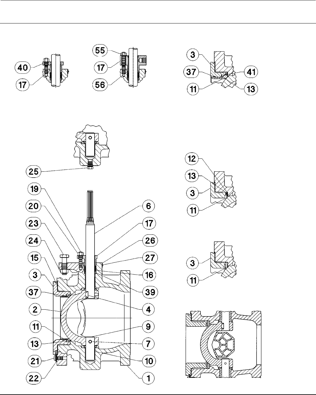
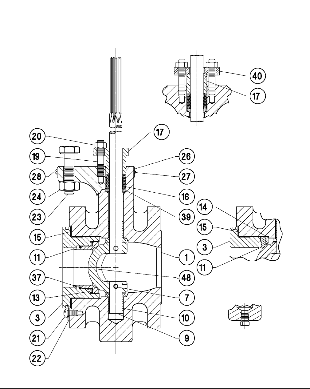
Figure 24. Fisher V150 or V300 NPS 3 through 12 Valve Assembly
(Details are typical for V200 flangeless valve body)
58B2296-D
ALLOY
FOLLOWER NPS 10 & 12
HD METAL SEAL
FOR ATTENUATOR
USE ONLY
LEAKOFF
FOLLOWER
FLAT METAL SEAL
TCM SEAL
PIPE PLUG
PARTS NOT SHOWN: 28, 30, 31, 32, 35 & 36
ATTENUATOR BALL
NPS 4-12
Instruction Manual
D101554X012
Vee-Ball Valves
January 2015
33
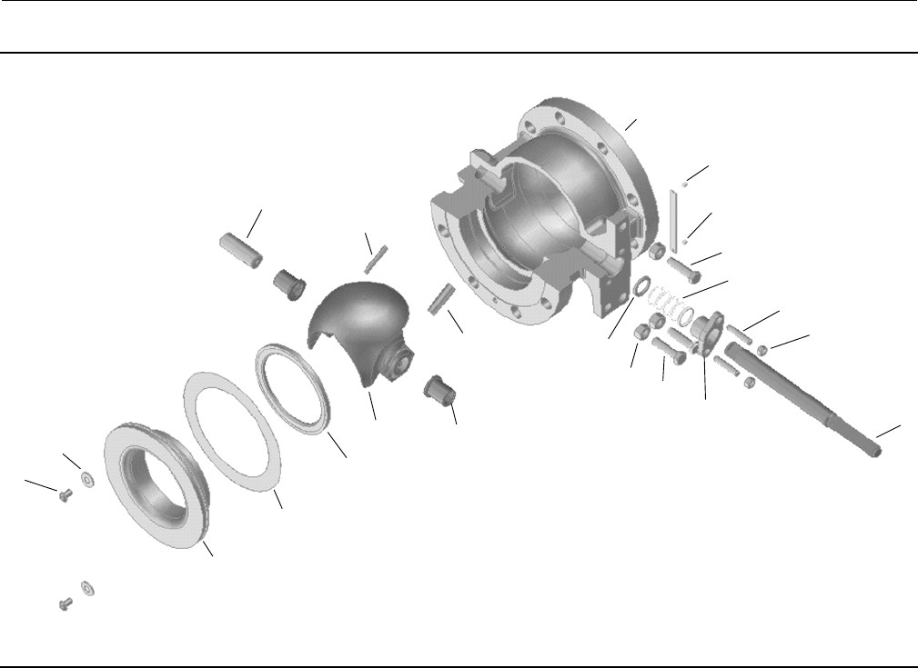
Figure 25. Exploded View, Fisher V150 and V300 NPS 3 through 12 without Attenuator Assembly.
1
2
3
4
6
7
9
27
26
23
16
19
20
39
24
23
17
21
22
15
11
10
Instruction Manual
D101554X012
Vee-Ball Valves
January 2015
34
Figure 26. Fisher V150 or V300 NPS 1, 1-1/2, and 2 Valve Assembly
(Details are typical for V200, except V200 does not have flanges)
44B2228-B
ALLOY ASSEMBLY
TCM SEAL
PIPE PLUG
OPTIONAL
NOTE:
PARTS NOT SHOWN: 30, 31, 32, 33, 35 & 36
Instruction Manual
D101554X012
Vee-Ball Valves
January 2015
35
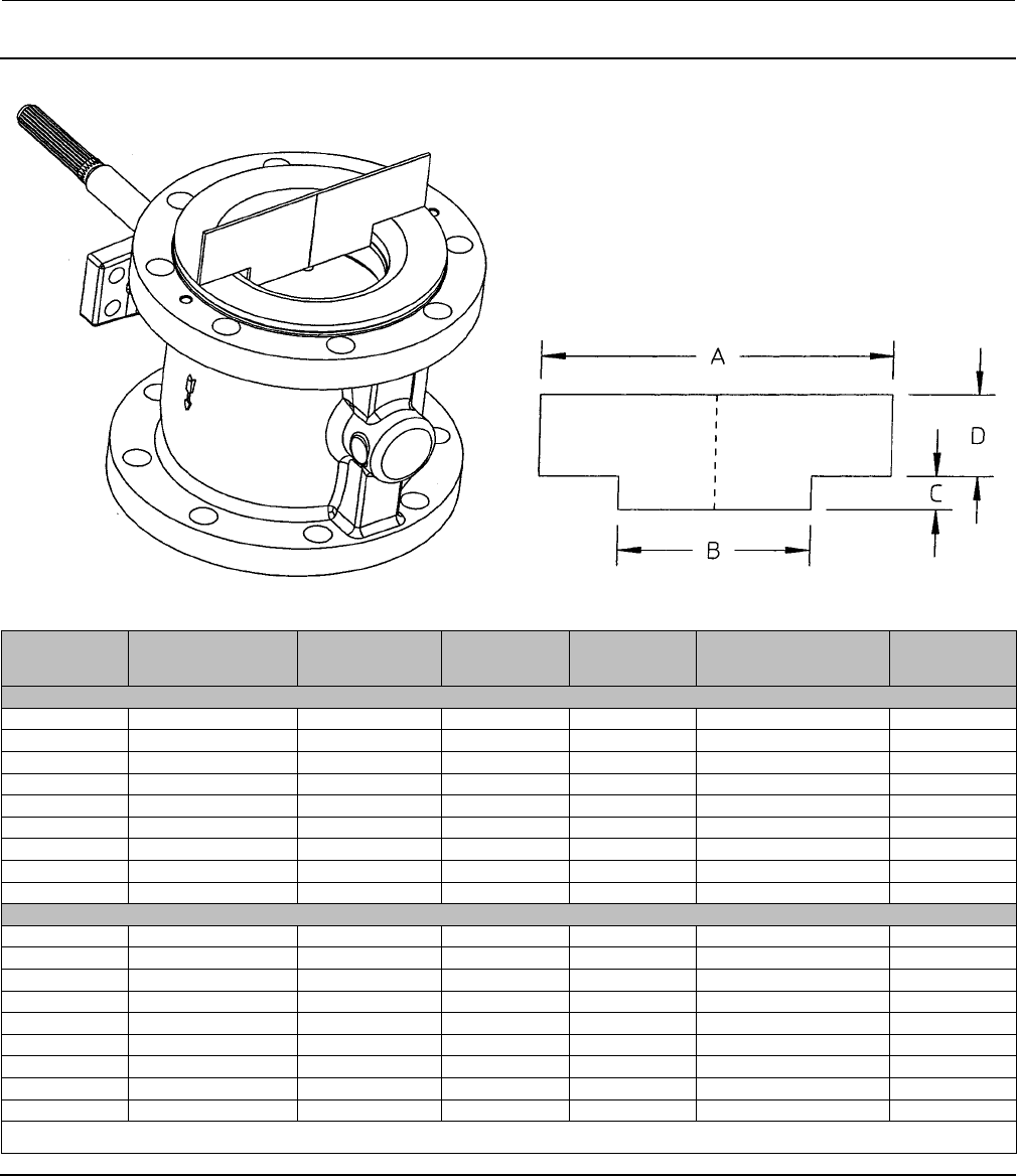
Figure 27. Centering Template in Use and Template Dimensions
19B8493
E0740
19B8493
E0741
VALVE SIZE, NPS A
(FOR ASME VALVES)
A
(FOR DIN VALVES) B(1)
C(1)
(ANSI/ISA
S75.08.02)
C
(ASME B16.10 Short(2))D(1)
mm
163 68 19 35 61 25
1-1/2 82 88 28 34 85 25
2102 102 38 31 85 25
3127 138 63 24 62 38
4157 157 82 36 71 44
6216 212 117 21 59 51
8270 268 139 12 61 57
10 324 320 203 235 60
12 381 378 254 220 63
Inches
12.50 2.68 0.75 1.40 2.40 1.00
1-1/2 3.25 3.46 1.12 1.34 3.34 1.00
24.02 4.02 1.50 1.22 3.34 1.00
35.00 4.55 2.50 0.94 2.44 1.50
46.19 6.19 3.25 1.42 2.80 1.75
68.50 8.35 4.62 0.82 2.32 2.00
810.62 10.55 5.50 0.48 2.42 2.25
10 12.75 12.60 8.00 0.09 1.40 2.38
12 15.00 14.88 10.00 0.09 0.78 2.50
1.ThesedimensionsarethesameforASMEandDINvalves.
2. Note that ASME B16.10 Short dimensions are actually longer than ANSI/ISA S75.08.02 dimensions.

Instruction Manual
D101554X012
Vee-Ball Valves
January 2015
36
Parts Ordering
A serial number is assigned to each valve and stamped on the nameplate. Always refer to the valve serial number when
corresponding with your Emerson Process Management sales office regarding spare parts or technical information.
When ordering replacement parts, also specify the complete 11-character part number from the parts kits or parts list
information.
WARNING
Use only genuine Fisher replacement parts. Components that are not supplied by Emerson Process Management should
not, under any circumstances, be used in any Fisher valve, because they will void your warranty, might adversely affect the
performance of the valve, and could give rise to personal injury and property damage.
Note
For the NPS 2 V150 valve, this manual covers valves with serial numbers 12551183 and higher. Always reference the serial number
of your valve when corresponding with your Emerson Process Management sales office.
Instruction Manual
D101554X012
Vee-Ball Valves
January 2015
37
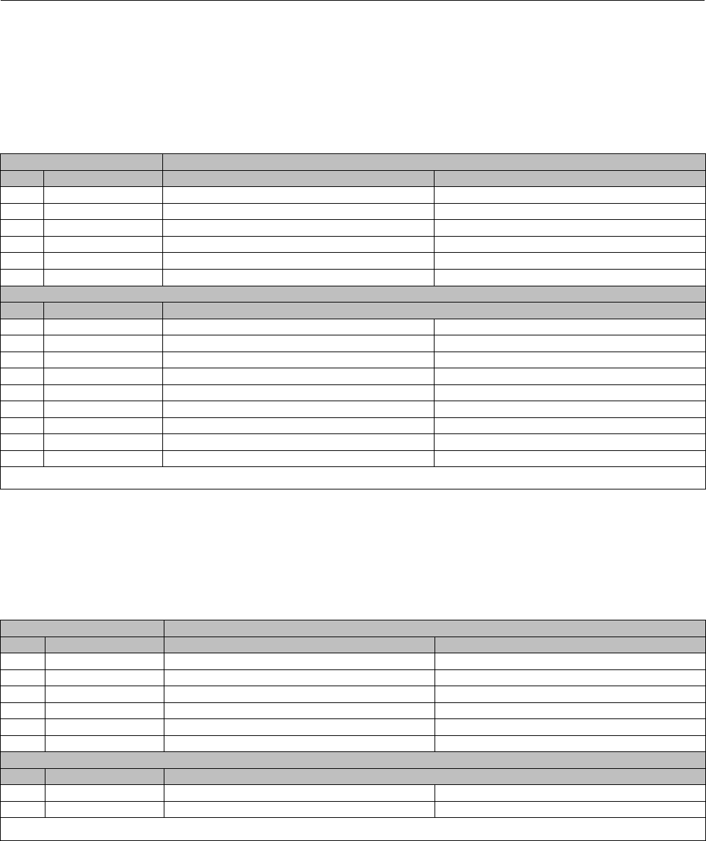
Retrofit Kits for ENVIRO-SEAL Packing
Retrofit kits include parts to convert existing V150, V200 and V300 valves with shallow (single packing depth) packing
box to the ENVIRO-SEAL packing box construction. Retrofit kits include single PTFE packing. See following table.
ENVIRO-SEAL Packing Retrofit Kits
SHAFT DIAMETER(1) PART NUMBER
mm Inches Single PTFE Graphite
12.7 1/2 RRTYXRT0012 RRTYXRT0312
15.9 5/8 RRTYXRT0022 RRTYXRT0322
19.1 3/4 RRTYXRT0032 RRTYXRT0332
25.4 1RRTYXRT0052 RRTYXRT0352
31.8 1-1/4 RRTYXRT0062 RRTYXRT0362
38.1 1-1/2 RRTYXRT0072 RRTYXRT0372
Parts Included in Kit
Key Description Quantity
100 Packing stud 2 2
101 Packing nut 2 2
102 Packing flange 1 1
103 Spring pack assembly 1 1
105 Packing set 1 1
106 Anti-extrusion washer 2---
107 Packing box ring(2) 1 1
--- Tag 1 1
--- Tie Cable 1 1
1. Diameter through the packing box.
2. Not required for all sizes of V150 and V200 or for V300 with 1-1/4 or 1-1/2 inch diameter shafts.
Repair Kits for ENVIRO-SEAL Packing
Repair kits include valves parts for shallow (single packing depth) for ENVIRO-SEAL packing box construction. Repair
kits include single PTFE or graphite packing. See following table.
ENVIRO-SEAL Packing Repair Kits
SHAFT DIAMETER(1) PART NUMBER
mm Inches PTFE Graphite
12.7 1/2 RRTYX000012 13B8816X012
15.9 5/8 RRTYX000022 13B8816X032
19.1 3/4 RRTYX000032 13B8816X052
25.4 1RRTYX000052 13B8816X092
31.8 1-1/4 RRTYX000062 13B8816X112
38.1 1-1/2 RRTYX000072 13B8816X142
Parts Included in Kit
Key Description Quantity
105 Packing set 1 1
106 Anti-extrusion washer 2---
(2)
1. Diameter through the packing box.
2. Included in key 105.
Instruction Manual
D101554X012
Vee-Ball Valves
January 2015
38
Repair Kits for Ball Seals
Seal repair kits include recommended spare parts for Fisher TCM Plus, S31600 stainless steel, CF10SMnN, or
CD7MCuN ball seal constructions. The following table indicates the repair kit part number and the quantity of parts
included in the kit.
Fisher V150, V200, and V300 Repair Kits
VALVE SIZE, NPS
KIT PART NUMBER
Ball Seal Material
TCM Plus --- Alloy 6 CD7MCuN
(Alloy 255 Duplex SST)
1
1-1/2
RV150X00CA2
RV150X00CB2
---
---
RV150XHDAA2
RV150XHDAB2
RV150XHDCA2
RV150XHDCB2
VALVE SIZE, NPS
Ball Seal Material
TCM Plus S31600
(316 SST) CF10SMnN CD7MCuN
(Alloy 255 Duplex SST)
2(1)
2(2)
3
4
6
8
10
12
RV150X00C12
RV150X00C82
RV150X00C22
RV150X00C32
RV150X00C42
RV150X00C52
RV150X00C62
RV150X00C72
RV150X00M12
---
RV150X00M22
RV150X00M32
RV150X00M42
RV150X00M52
RV150X00M62
RV150X00M72
RV150X0HD12
RV150X0H082
RV150X0HD22
RV150X0HD32
RV150X0HD42
RV150X0HD52
RV150X0HD62
RV150X0HD72
RV150XHDC12
RV150XHDC82
RV150XHDC22
RV150XHDC32
RV150XHDC42
RV150XHDC52
RV150XHDC62
RV150XHDC72
Parts Included in Kit Quantity in Kit
Key No. Description
11
12
13
13
Ball seal
Shim seal(3)
Spring seal
Wave spring
1
---
---
---
1
4
1
---
1
---
---
1
1
---
---
1
15
37
21
22
Gasket
Radial seal
Retainer screw
Retainer washer
1
---
2or4
(4)
2or4
(4)
1
---
2or4
(4)
2or4
(4)
1
1
2or4
(4)
2or4
(4)
1
1
2or4
(4)
2or4
(4)
1. V150’s only for serial numbers below 12551183.
2. V150’s for serial numbers 12551183 and above. All V200’s and V300’s.
3. Fewer shim seals are furnished in the parts kits than are used in the original construction of the valve. Most original shim seals can be reused.
4. A quantity of 2 is supplied for NPS 2 through 8 valves, and a quantity of 4 is supplied for NPS 10 and 12 valves.

Instruction Manual
D101554X012
Vee-Ball Valves
January 2015
39
Parts List
Note
Part numbers are shown for recommended spares only. For other part
numbers, contact your Emerson Process Management sales office.
Common Parts (figures 24, 25 &
26)
Key Description Part Number
1 If you need a valve body as a replacement part, order by valve
size, serial number, and desired valve body material. Contact your
Emerson Process Management sales office for assistance.
2* Ball see following table
2* Ball w/ attenuator see following table
3SealProtectorRing
4* Taper Key
R30006 (cobalt alloy 6 casting)
NPS 3 and 4 12B9530X012
NPS 6 12B9531X012
NPS 8 & 10 12B9532X012
NPS 12 12B9533X012
N10276
NPS 3 and 4 11B0674X032
NPS 6 11B0695X032
NPS 8 & 10 11B0722X032
NPS 12 11B4684X032
6* Drive Shaft see following table
6* Drive Shaft w/ attenuator see following table
7* Groove Pin
S31600 (316 stainless steel)
NPS 1 13B0345X012
NPS 1-1/2 and 2 11B0705X012
NPS 3 and 4 18A6135X012
NPS 6 18A6138X012
NPS 8 11B0738X012
NPS 10 and 12 11B8596X012
N10276
NPS 1 13B0345X022
NPS 1-1/2 and 2 11B0705X022
NPS 3 and 4 18A6135X022
NPS 6 18A6138X032
9* Follower Shaft see following table
9* Follower Shaft w/ attenuator see following table
10* Bearing (2 req'd)
PEEK/PTFE
NPS 1 14B3351X012
NPS 1-1/2 14B3352X012
NPS 2 14B3353X012
NPS 3 and 4 17B7142X012
NPS 6 27B7136X012
NPS 8 and 10 27B7775X012
NPS 12 27B9470X012
R30016 (alloy 6B)
NPS 1 23B0342X012
NPS 1-1/2 23B6819X022
NPS 2 23B6682X012
Key Description Part Number
NPS 3 and 4 27B9673X012
NPS 6 27B9670X012
NPS 8 and 10 27B9547X012
NPS 12 27B9471X012
Silver-plated R30016 (alloy 6B)
NPS 1 23B0343X012
NPS 1-1/2 23B6820X012
NPS 2 23B6683X012
NPS 3 and 4 28B2950X012
NPS 6 28B2951X012
NPS 8 and 10 28B2952X012
NPS 12 28B2953X012
316L SST Nitride
NPS 1 23B0342X032
NPS 1-1/2 23B6819X032
NPS 2 23B6682X032
NPS 3 and 4 27B9673X022
NPS 6 27B9670X022
NPS 8 and 10 27B9547X022
NPS 12 27B9471X022
Carbon-filled PTFE with N10276 sleeve
NPS 1 13B0349X012
NPS 1-1/2 13B6822X012
NPS 2 13B6685X012
NPS 3 and 4 17B9675X012
NPS 6 27B9672X012
NPS 8 and 10 27B9549X012
NPS 12 27B9472X012
Glass-filled PTFE with N10276 sleeve
NPS 1 13B0349X042
NPS 1-1/2 13B6822X042
NPS 2 13B6685X022
NPS 3 and 4 17B9675X022
NPS 6 27B9672X022
NPS 8 and 10 27B9549X022
NPS 12 27B9473X022
11* Ball Seal
Fisher TCM Plus
NPS 1 13B0339X052
NPS 1-1/2 13B6815X062
NPS 2 13B6686X062
NPS 3 13A2565X102
NPS 4 13A2585X102
NPS 6 13A2619X102
NPS 8 13A2645X072
NPS 10 13A2662X052
NPS 12 13A2677X062
Fisher TCM Ultra
NPS 1 13B0339X062
NPS 1-1/2 13B6815X072
NPS 2 13B6686X072
NPS 3 13A2565X112
NPS 4 13A2585X112
NPS 6 13A2619X112
NPS 8 13A2645X082
NPS 10 13A2662X062
NPS 12 13A2677X072
Flat Metal
S31600
NPS 3 11B4688X012
NPS 4 11B5704X012
NPS 6 11B5708X012
NPS 8 11B5712X012
NPS 10 11B5717X012
*Recommended spare parts

Instruction Manual
D101554X012
Vee-Ball Valves
January 2015
40
Key Description Part Number
S30200
NPS 12 11B5722X012
HD (Heavy-Duty) Metal
CF10SMnN
NPS 2 33B6676X012
NPS 3 34B4766X012
NPS 4 34B4767X012
NPS 6 34B4768X012
NPS 8 34B4769X012
NPS 10 34B3365X012
NPS 12 34B3366X012
CD7MCuN SST
NPS 1 33B0341X022
NPS 1-1/2 33B6817X022
NPS 2 33B6676X022
NPS 3 34B4766X022
NPS 4 34B4767X022
NPS 6 34B4768X022
NPS 8 34B4769X022
NPS 10 34B3365X022
NPS 12 34B3366X022
R30006 cobalt alloy 6 casting
NPS 1 33B0341X012
NPS 1-1/2 33B6817X032
NPS 2 33B6676X032
NPS 3 34B4766X032
NPS 4 34B4767X032
NPS 6 34B4768X032
NPS 8 34B4769X032
S31700 (317 SST) w/ CoCr-A seat
NPS 10 34B3365X032
NPS 12 34B3366X032
12* Shim Seal, S31600 (12 req'd)
Use w/flat metal seal only
NPS 3 11B4689X012
NPS 4 11B5706X012
NPS 6 11B5710X012
NPS 8 11B5714X012
NPS 10 11B5718X012
NPS 12 11B5721X012
13* Spring Seal, S31600
Use w/ flat metal seal only
NPS 3 21B4687X012
NPS 4 21B5705X012
NPS 6 21B5707X012
NPS 8 21B5713X012
NPS 10 21B5716X012
NPS 12 21B5720X012
13* Wave Spring, N07750 (NACE)
use w/ HD Metal Seal only
NPS 1 23B0347X012
NPS 1-1/2 23B6825X012
NPS 2 23B6689X012
NPS 3 24B4760X012
NPS 4 24B4761X012
NPS 6 24B4762X012
NPS 8 24B4763X012
NPS 10 22B4509X012
NPS 12 22B4514X012
14 Backup Ring (Composition seal only)
15* Gasket
Graphite laminate (Standard)
NPS 1 13B0344X032
NPS 1-1/2 13B6823X042
Key Description Part Number
NPS 2 13B6687X052
NPS 3 11B0660X042
NPS 4 11B0672X052
NPS 6 11B0681X032
NPS 8 11B0693X032
NPS 10 11B0720X022
NPS 12 11B4682X022
Graphite for Oxygen Service
NPS 1 13B0344X022
NPS 1-1/2 13B6823X022
NPS 2 13B6687X022
NPS 3 11B0660X052
NPS 4 11B0672X062
NPS 6 11B0681X042
NPS 8 11B0693X042
NPS 10 11B0720X032
NPS 12 11B4682X032
16* Packing Set, PTFE and carbon-filled PTFE V-ring
NPS 1 12A9016X022
NPS 1-1/2 and 2 1R5795X0012
NPS 3 and 4 12A8995X022
NPS 6 12A8832X022
NPS 8 and 10 12A8951X022
NPS 12 12A8935X022
17 Packing Follower w/integral flange
17 Packing Follower w/o integral flange
19 Packing Follower Stud
20 Packing Follower Nut
21 Seal Protector Screw
22 Seal Protector Clip
23 Actuator Mounting Screw
24 Actuator Mounting Nut
25 Pipe Plug (Optional) (not shown)
26 Identification Nameplate 15A0460X012
27 Drive Screw
28 Flow Arrow
30 Nameplate
31 NameplateWire(notshown)
32 Line Flange Stud
33 Line Flange Stud
34 Spacer
35* Packing Ring, graphite ribbon (4 req'd)
NPS 1 12A9134X012
NPS 1-1/2 and 2 12A9135X012
NPS 3 and 4 12A9136X012
NPS 6 12A9137X012
NPS 8 and 10 12A9138X012
NPS 12 12A9139X012
36* Packing Washer, zinc
NPS 1 (3 req'd) 14A8362X012
NPS 1-1/2 and 2 14A9771X012
NPS 3 and 4 (3 req'd) 14A8363X012
NPS 6 (3 req'd) 14A8365X012
NPS 8 and 10 (3 req'd) 14A8366X012
NPS 12 (3 req'd) 14A8367X012
37* Radial Seal, PTFE/CG
Use w/HD Metal Seal
NPS 1 18B0261X012
NPS 1-1/2 18B0262X012
NPS 2 18B0263X012
NPS 3 18B0264X012
NPS 4 28B0265X012
NPS 6 28B0266X012
NPS 8 28B0267X012
*Recommended spare parts

Instruction Manual
D101554X012
Vee-Ball Valves
January 2015
41
Key Description Part Number
NPS 10 28B0268X012
NPS 12 28B0269X012
39* Packing Box Ring
316 SST
NPS 1 16A6082X012
NPS 1-1/2 and 2 16A6083X012
NPS 3 and 4 16A6084X012
NPS 6 16A6085X012
NPS 8 and 10 16A6086X012
NPS 12 16A6087X012
N10276
NPS 1 16A6082X092
NPS 1-1/2 and 2, N04400 16A6083X102
NPS 3 and 4 16A6084X072
NPS 6 16A6085X092
NPS 8 and 10 16A6086X062
NPS 12 16A6087X092
40 Packing Flange
41 Retaining Ring
48* Ball-Shaft Assembly see following table
130 Clamp
131 Bonding Strap Assembly
ENVIRO-SEAL Packing System
(Parts in all Type Vee-Ball Valves)
(figure 5)
Key Description Part Number
100 Packing Flange Stud
101 Packing Flange Nut
102 Packing Flange
103 Spring Pack Assembly
Key Description Part Number
105* Packing Set
W/single PTFE packing
NPS 1 12B7053X012
NPS 1-1/2 and 2 12B7402X012
NPS 3 12B7414X012
NPS 4 12B7414X012
NPS 6 12B7438X012
NPS 8 and 10 12B7450X012
NPS 12 12B7462X012
106* Anti-Extrusion Ring (2 req'd)
W/single and double PTFE packing
NPS 1 12B7054X012
NPS 1-1/2 and 2 12B7406X012
NPS 3 and 4 12B7418X012
NPS 6 12B7442X012
NPS 8 and 10 12B7454X012
NPS 12 w/single PTFE packing only 12B7466X012
107* Packing Box Ring
W/single and double PTFE packing
NPS 1 16A6082X012
NPS 1-1/2 and 2 16A6083X012
NPS 3 and 4 16A6084X012
NPS 6 16A6085X012
108* Packing Ring (2 req'd)
W/double PTFE packing
NPS 1 1H7844X0012
NPS 1-1/2 and 2 1R5794X0012
NPS 3 and 4 12A8992X022
NPS 6 12A8831X022
NPS 8 and 10 12A8953X022
109* Anti-Extrusion Ring (2 req'd)
W/double PTFE packing
NPS 1 (adapter rings) 12B7473X012
and (anti-extrusion rings) 12B7054X012
NPS 1-1/2 and 2 (adapter rings) 12B7410X012
and (anti-extrusion rings) 12B7406X012
NPS 3 and 4 PTFE packing 12B7422X012
NPS 6 PTFE packing 12B7446X012
NPS 8 and 10 PTFE packing 12B7458X012
110 Lantern Ring
111 Tag
112 Tie Cable
113 Lubricant, anti-seize (not furnished with packing
system)
*Recommended spare parts
1. Chrome-plated ball (CRPL)
2. CF3M is the standard material offered in Europe only.
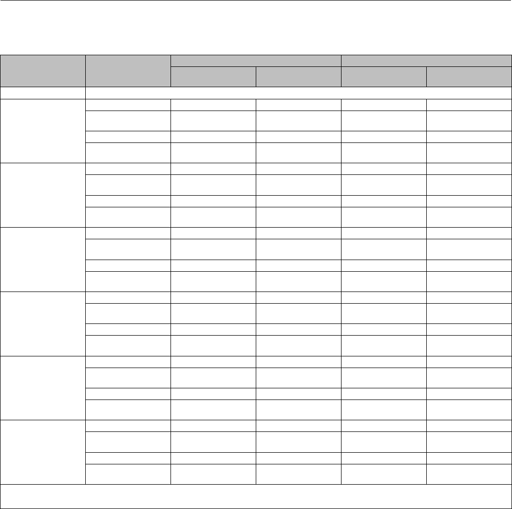
Instruction Manual
D101554X012
Vee-Ball Valves
January 2015
42
Key 2*. Series B Design Ball for NPS 3 through 12 Valves (without attenuator)
Valve NPS Ball Material(1)
RH/LH(3) Mounted Actuator - Standard LH Mounted Actuator - Optional
Ball for use with TCM
seals
Ball for use with all
other seals
Ball for use with TCM
seals
Ball for use with all
other seals
1, 1-1/2, 2 ----------- see key 48 -------------
3
Chrome Plated CG8M GE11071X222 34B8330X572 GE11078X082 38B6978X122
Chrome Plated CG8M
w/CoCR-A Notch GE11071X272 34B8330X582 GE11078X092 38B6978X132
Chrome Plated CF3M(2) GE11071X292 34B8330X502 GE11078X112 38B6978X152
Chrome Plated CF3M
w/CoCR-A Notch GE11071X302 34B8330X592 GE11078X122 38B6978X162
4
Chrome Plated CG8M GE11072X302 37B1866X672 GE11079X112 38B6979X112
Chrome Plated CG8M
w/CoCR-A Notch GE11072X282 37B1866X552 GE11079X122 38B6979X122
Chrome Plated CF3M(2) GE11072X322 37B1866X572 GE11079X142 38B6979X142
Chrome Plated CF3M
w/CoCR-A Notch GE11072X332 37B1866X582 GE11079X152 38B6979X152
6
Chrome Plated CG8M GE11073X312 47B1737X372 GE11080X112 48B6980X152
Chrome Plated CG8M
w/CoCR-A Notch GE11073X322 47B1737X492 GE11080X122 48B6980X162
Chrome Plated CF3M(2) GE11073X342 47B1737X512 GE11080X142 48B6980X182
Chrome Plated CF3M
w/CoCR-A Notch GE11073X352 47B1737X522 GE11080X152 48B6980X192
8
Chrome Plated CG8M GE11074X282 44B8352X332 GE11081X092 48B6981X162
Chrome Plated CG8M
w/CoCR-A Notch GE11074X292 44B8352X502 GE11081X102 48B6981X172
Chrome Plated CF3M(2) GE11074X312 44B8352X522 GE11081X122 48B6981X192
Chrome Plated CF3M
w/CoCR-A Notch GE11074X322 44B8352X532 GE11081X132 48B6981X202
10
Chrome Plated CG8M GE11075X262 44B8641X342 GE11082X082 48B6982X132
Chrome Plated CG8M
w/CoCR-A Notch GE11075X272 44B8641X272 GE11082X092 48B6982X142
Chrome Plated CF3M(2) GE11075X242 44B8641X452 GE11082X112 48B6982X162
Chrome Plated CF3M
w/CoCR-A Notch GE11075X292 44B8641X462 GE11082X122 48B6982X172
12
Chrome Plated CG8M GE11076X242 47B1405X362 GE11083X082 48B6983X102
Chrome Plated CG8M
w/CoCR-A Notch GE11076X252 47B1405X372 GE11083X092 48B6983X112
Chrome Plated CF3M(2) GE11076X272 47B1405X392 GE11083X112 48B6983X132
Chrome Plated CF3M
w/CoCR-A Notch GE11076X282 47B1405X402 GE11083X122 48B6983X142
1. For materials not shown, contact your Emerson Process Management sales office
2. For Europe and Asia manufacture
3. With Standard LH mount the ball will rotate open to the bottom on the valve body
*Recommended spare parts

Instruction Manual
D101554X012
Vee-Ball Valves
January 2015
43
Key 2*. Ball (With attenuator)
Chrome Plated CG8M ball, CG8M attenuator (right hand mounted actuator- standard)
NPS 4 valve 38B6522X012
NPS 6 valve 48B6523X012
NPS 8 valve 48B6525X012
NPS 10 valve 48B6527X012
NPS 12 valve 48B6529X012
Chrome Plated CG8M ball, CG8M attenuator (left hand mounted actuator - optional)
NPS 4 valve 38B6522X012
NPS 6 valve 48B6524X012
NPS 8 valve 48B6526X012
NPS 10 valve 48B6528X012
NPS 12 valve 48B6530X012
Key 6*. Spline Drive Shaft for Non-attenuated Series B Design Ball - (RH/LH Standard)
S20910
NPS 1, 1-1/2, and 2 valves see key 48 table
NPS 3 and 4 valves 37B2506X022
NPS 6 valve 37B2507X022
NPS 6 CL600 valve 37B2751X022
NPS 8 and 10 valves 37B2508X022
NPS 8 and 10 valves 37B2509X022
N10276
NPS 1, 1-1/2, and 2 valves see key 48 table
NPS 3 and 4 valves 37B2506X032
NPS 6 valve 37B2507X032
NPS 8 and 10 valves 37B2508X032
NPS 8 and 10 valves 37B2509X032
S31254
NPS 1, 1-1/2, and 2 valves see key 48 table
NPS 3 and 4 valves 37B2506X052
NPS 6 valve 37B2507X052
NPS 8 and 10 valves 37B2508X052
NPS 8 and 10 valves 37B2509X052
Key 6*. Spline Drive Shaft for Non-attenuated Series B Design Ball - (LH Optional)
S20910
NPS 3 and 4 valves 38B7551X022
NPS 6 valve 38B7552X022
NPS 6 CL600 valve 38B7553X022
NPS 8 and 10 valves 38B7554X022
NPS 12 valve 38B7555X022
Key 6*. Spline Drive Shaft for Attenuated Ball- (RH/LH Standard)
S20910
NPS 4 valve 21B0668X012
6-inch valve 31B0732X012
NPS 6 CL600 valve 37B0528X022
NPS 8 and 10 valves 31B0716X012
NPS 12 valve 31B4678X012
*Recommended spare parts
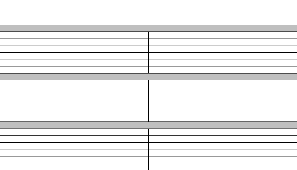
Instruction Manual
D101554X012
Vee-Ball Valves
January 2015
44
Key 9*. Follower Shaft
S20910
NPS 1 valve 13B0336X012
NPS 1-1/2 and 2 valves 13B6678X012
NPS 3 and 4 valves 11B0728X012
NPS 6 valve 11B0733X012
NPS 8 and 10 valves 11B0717X012
NPS 12 valve 11B4679X012
N10276
NPS 1 valve 13B0336X022
NPS 1-1/2 and 2 valves 13B6678X022
NPS 3 and 4 valves 11B0728X022
NPS 6 valve 11B0733X022
NPS 8 and 10 valves 11B0717X022
NPS 12 valve 11B4679X032
S31254
NPS 1 valve 13B0336X052
NPS 1-1/2 and 2 valves 13B6678X062
NPS 3 and 4 valves 11B0728X132
NPS 6 valve 11B0733X092
NPS 8 and 10 valves 11B0717X102
NPS 12 valve 11B4679X092
*Recommended spare parts
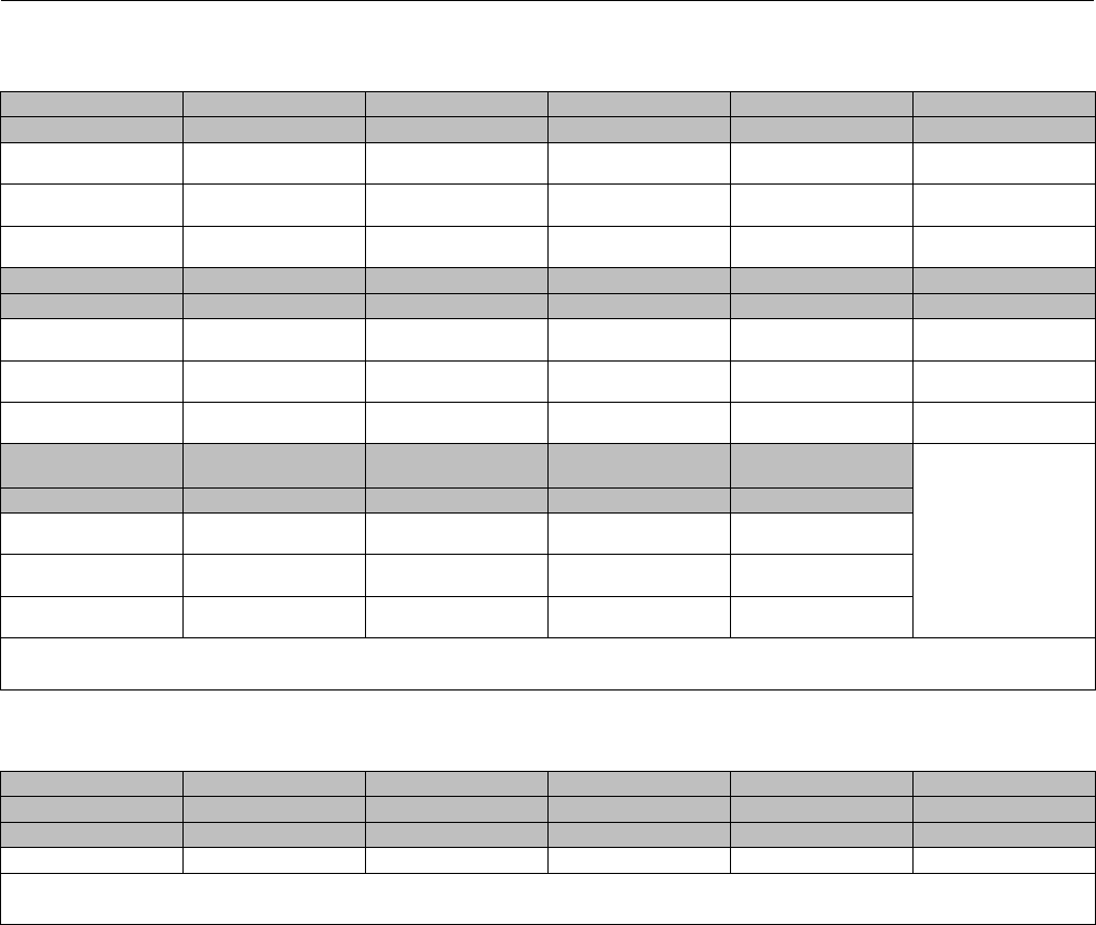
Instruction Manual
D101554X012
Vee-Ball Valves
January 2015
45
Key 48*. Ball/Spline Shaft Assembly for NPS 1, 1-1/2, and 2 Valves
Ball Material(3) CG8M CRPL(1) CG8M CRPL(1) CG8M CG8M CW2M
Shaft Material(3) S20910 S17400 S20910 S17400 N10276
NPS 1 Valve
(1/2-Inch shaft) 29B9535X652 29B9535X722 29B9535X642 29B9535X712 29B9535X052
NPS 1-1/2 Valve
(5/8-Inch shaft) 39B9542X592 39B9542X652 39B9542X582 39B9542X642 39B9542X052
NPS 2 Valve
(5/8-Inch shaft) 39B9547X472 39B9547X862 39B9547X792 39B9547X852 39B9547X052
Ball Material CF3M CRPL(2) CF3M CRPL(2) CF3M CF3M CK3MCUN
Shaft Material (cont.) S20910 S17400 S20910 S17400 S31254
NPS 1 Valve
(1/2-Inch shaft) 29B9535X682 29B9535X752 29B9535X672 29B9535X742 29B9535X152
NPS 1-1/2 Valve
(5/8-Inch shaft) 39B9542X622 39B9542X682 39B9542X612 39B9542X672 39B9542X152
NPS 2 Valve
(5/8-Inch shaft) 39B9547X812 39B9547X892 39B9547X802 39B9547X882 39B9547X152
Ball Material CG8M CRPL with
CoCR-A Notch
CG8M CRPL with
CoCR-A Notch
CF3M CRPL with
CoCR-A Notch
CF3M CRPL with
CoCR-A Notch
Shaft Material (cont.) S20910 S17400 S20910 S17400
NPS 1 Valve
(1/2-Inch shaft) 29B9535X662 29B9535X732 29B9535X692 29B9535X762
NPS 1-1/2 Valve
(5/8-Inch shaft) 39B9542X602 39B9542X662 39B9542X632 39B9542X692
NPS 2 Valve
(5/8-Inch shaft) 39B9547X742 39B9547X872 39B9547X822 39B9547X902
1. Chrome Plated ball (CRPL).
2. CF3M is for Europe and Asia manufacture.
3. For materials or shaft sizes not shown contact your Emerson Process Management sales office.
Key 48*. Ball/Spline Shaft Assembly for NPS1ValveswithMicro-NotchVee-Ball
(1)
Mounting Right Hand Right Hand Right Hand Right Hand Right Hand
Ball Material(3) CG8M CRPL(2) CG8M CRPL(2) CF3M CRPL(2) CF3M CRPL(2) R30006
Shaft Material S20910 S17400 S20910 S17400 S20910
NPS 1 Valve GE47969X062 GE47969X072 GE47969X082 GE47969X092 39B9540X022
1. For VTC ceramic Micro-Notch ball materials contact your Emerson Process Management sales office.
2. Chrome Plated ball (CRPL).
3. CF3M is for Europe and Asia manufacture.
*Recommended spare parts

Instruction Manual
D101554X012
Vee-Ball Valves
January 2015
46
Appendix A
Instructions for Non-Series B
The Series B changes affected only the NPS 3 through 12 valves without attenuators. To determine if a Vee-Ball valve is
Series B, you will need to examine several of the internal parts. Compare the distinctive skirted V-notch outline of the
forwardsideandthecircularedgeonthereversesideoftheSeriesBdesignballtotheV-notchonbothsidesofthe
non-series B design ball. Then look for bushings. The lack of bushings indicates the valve body is Series B.
All Vee-Ball valves NPS 3 through 12 produced before the Series B design changes use the Specifications table, the
Installation, Maintenance, Packing Maintenance, Replacing Packing, and Replacing the Ball Seal instructions found
elsewhere in this manual. Bearing and Vee-Ball Maintenance and Actuator Mounting instructions for these valves may
be found below.
Maintenance
WARNING
The Vee-ball closes with a shearing, cutting motion, which could result in personal injury. To avoid injury, keep hands,
tools, and other objects away from the Vee-ball while stroking the valve.
Avoid personal injury from sudden release of process pressure. Before performing any maintenance operations:
DDo not remove the actuator from the valve while the valve is still pressurized.
DDisconnect any operating lines providing air pressure, electric power, or a control signal to the actuator. Be sure the
actuator cannot suddenly open or close the valve.
DUse bypass valves or completely shut off the process to isolate the valve from process pressure. Relieve process pressure
from both sides of the valve. Drain the process media from both sides of the valve.
DVent the power actuator loading pressure and relieve any actuator spring precompression.
DUse lock-out procedures to be sure that the above measures stay in effect while you work on the equipment.
DAlways wear protective gloves, clothing, and eyewear when performing any maintenance operations to avoid personal
injury.
DThe valve packing area may contain process fluids that are pressurized, even when the valve has been removed from the
pipeline. Process fluids may spray out under pressure when removing the packing hardware or packing rings.
DCheck with your process or safety engineer for any additional measures that must be taken to protect against process
media.
Procedures for disassembly and assembly of the bearings and ball cannot be accomplished until the ball seal and valve
packing are removed from the valve.
1. Refer to the Replacing Packing procedures to remove the actuator, and to remove the packing flange and packing
follower from the valve. When the packing disassembly steps are complete, return to this section.
2. Refer to the Replacing the Ball Seal procedures to remove the ball seal from the valve.
Disassembly
WARNING
When the actuator is removed from the valve, the ball/shaft assembly may suddenly rotate, with a shearing, cutting
motion, which could result in personal injury. To avoid injury, carefully rotate the ball to a stable position. Make sure the
ball will not rotate.
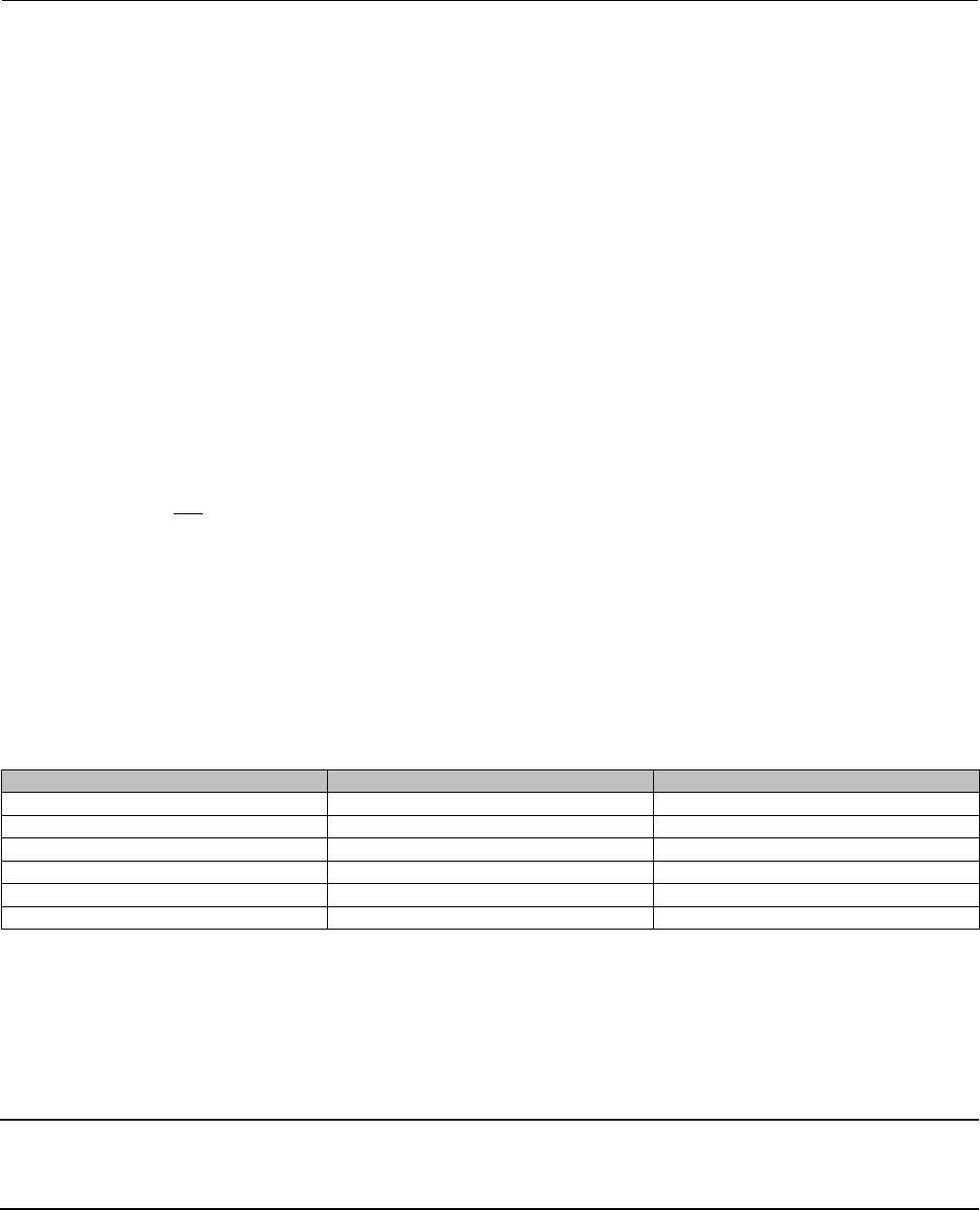
Instruction Manual
D101554X012
Vee-Ball Valves
January 2015
47
Key numbers in this procedure are shown in figures 24, 26, and 31, unless otherwise indicated. A taper key (key 4,
figure 14) is used in NPS 3 through 12 Non-Series B valves.
3. Carefully rotate the ball to the open position after the actuator is disconnected. Make sure the ball will not rotate
(see warning above). Provide support for the ball during the following disassembly.
4. Unscrew the pipe plug (key 25). (With newer valve constructions, the pipe plug is optional and may not be
available.)
5. Working from the small end of the groove pin (key 7), use a pin punch to drive the groove pin out of the ball ear and
follower shaft.
For tack welded taper keys, driving the taper key out of the ball ear will shear the tack welding.
6. Locatethesmallendofthetaperkey(key4,seefigure14).Usingapinpunchonthesmallerendofthetaperkey,
drive it out of the ball (key 2) and drive shaft (key 6). Note: driving the taper key in the wrong direction will tighten
it.
7. Pullthedriveshaft(key6)outoftheactuatorsideofthevalvebody.
8. Make sure the sealing surface of the ball is not damaged while removing the follower shaft.
a. If a pipe plug (key 25) is installed, use a punch to drive the follower shaft (key 9) into the center of the ball.
b. If a pipe plug is not installed, use a piece of continuous threaded rod as a removal rod when moving the follower
shaft (key 9) into the center of the V-notch ball. Refer to the table 7 for a description of the size threaded rod
needed. The length of the rod should allow easy working room from the valve body.
9. Remove the ball (key 2) by carefully removing the follower shaft and ball from the valve body.
10. Remove the packing box spacer (key 34) for NPS 8, 10, and 12 valves.
11. Removing the bearings (key 10):
a. For composition bearings, remove the bearings by hand. If the bearings are tight in the valve body, then pull or
drivethemoutwithaslightpressure.Allowthebushings(key5or8)toremaininthevalvebody.
Table 7. Continuous Threaded Rod
Valve Size, NPS Threaded Rod Thread Size ThreadDepthinFollowerShaft
31/4-20 0.5
41/4-20 0.5
61/4-20 0.5
85/16-18 0.62
10 5/16-18 0.62
12 5/16-18 0.94
b. For metal bearings, useapressandramtoremovethedriveshaftbearingsoutofthevalvebody.Refertofigures
29 and 30 ram dimensions. The bushings (key 5 or 8) will normally remain in the valve body.
To remove the follower shaft bearings, use a blind-hole bearing puller. If you do not have such a tool, you can machine
the bearing out.
Note
For proper shutoff performance, the ball and seal require the bearing (key 10) to be positioned correctly. If you removed the
bearings (key 10), be sure to locate the new bearings as shown in figures 29 and 30.
Instruction Manual
D101554X012
Vee-Ball Valves
January 2015
48
12. Thoroughly clean surfaces of all parts that are to be re-used or obtain replacement parts.
Assembly
1. Inspect all sealing surfaces to ensure they are in good condition and without scratches or wear.
2. Installing bearings (key 10):
a. For composition bearings, install the bearings by hand. The bearing flanged end should touch the bushing (key 5
or 8).
b. For metal bearings:
DUse a press and ram to install the bearings (key 10). Refer to figures 29 and 30.
DPress the bearings in until each bearing is flush with the bushing (key 5 or 8). The acceptable tolerance for bearing
location is: flush with the bushing to 1.52 mm (0.060 inches) inside the bushing. That is, the bearings should not
protrude into the flow cavity of the valve, and they should not be more than 1.52 mm (0.060 inches) inside the
bushing.
DTake care not to change the position of the bushings (key 5 or 8) when pressing in new bearings (key 10), otherwise
the ball will not center in the valve body and seal.
3. Installing the Vee-Ball (key 2):
WARNING
The Vee-Ball might be damaged if it is allowed to fall into the valve body. To avoid personal injury or damage to the sealing
surfaces, support the ball to prevent it from falling into or out of the valve body cavity.
Note
For ease of assembly, the follower shaft (key 9) should be inserted into the ball before installing the ball in an NPS 3 valve without
ball/attenuator.
Carefully install the ball into the valve body cavity.
After you have installed the ball (key 2) into the valve body assembly, firmly support the ball while installing the shafts.
4. Installing the follower shaft (key 9):
DFor NPS 3 valves: The follower shaft (key 9) should already have been inserted into the ballbeforetheballwasput
into the valve body. Insert the follower shaft (key 9) into the valve body bearing (key 10).
DFor NPS 4 and larger valves without attenuator: Insert the follower shaft (key 9) through the ball, and into the valve
body bearing (key 10).
Then for all sizes, align the hole in the follower shaft with the holes in the ball. Insert the small end of the groove pin
(key 7) into the hole in the ball and into the follower shaft. The pin will hold the parts in place while the drive shaft (key
6) is being installed.
5. Insertthedriveshaft(key6)intothevalvebodybearing(key10),andintotheballear.Aligntheholeinthedrive
shaft with the holes in the ball.
CAUTION
The drive shaft must be used with the correct Vee-Ball. Refer to the tag (see figure 13) attached to the Vee-Ball and to the
drive shaft.
Instruction Manual
D101554X012
Vee-Ball Valves
January 2015
49
Failure to use the correct Vee-Ball/ shaft combination may result in the ball not being in the position indicated by the slash
mark on the end of the shaft. If the ball is not properly aligned with the slash mark, the valve will not function correctly and
seal damage may result.
6. InstallingtheTaperKey(key4):
Current standard construction materials for all NPS 3 through 12 valves require the taper key (key 4, figure 14) to be
tack welded in place using the following procedure. Use standard welding preparations when preparing parts for
reassembly.
CAUTION
Make sure the drive shaft (key 6) is free of oil or grease, otherwise the taper key will not seat properly. Failure to properly
set the taper pin or taper key could result in it coming loose while in service. Loosening of the taper key in service could
result in improper valve function and equipment damage.
1. Install the drive shaft (key 6) into the valve body through the ball and into the lower bearing.
2. Insert the taper key (key 4) into ball and drive shaft (keys 2 and 6) as shown in figure 14. The taper key inserts, with
theflatsideofthekey,facingthedriveshaft(key6).
3. Using a flat end punch, drive the groove pin (key 7) into the ball ear and follower shaft until it is flat with the ball ear
surface.
4. Using a flat end punch, drive the taper key (key 4) into the ball ear and drive shaft (key 6) until solid, heavy contact is
obtained between the key and shaft.
5. Measure the position of the taper key head.
6. Drive the taper key in further using the minimum distance shown in table 7.
Table 8. Taper Key Minimum Depth
VALVE SIZE, NPS MINIMUM DEPTH TO DRIVE TAPER KEY AFTER INITIAL SOLID CONTACT, mm (INCHES)
3, 4, 6
8, 10, 12
4.8 (0.188)
5.6 (0.219)
Table 9. Taper Key Maximum Depth
VALVE SIZE, NPS MAXIMUM DEPTH TO DRIVE TAPER KEY AFTER INITIAL SOLID CONTACT, mm (INCHES)
3, 4
6
8, 10
12
7.1 (0.281)
7.9 (0.312)
9.5 (0.375)
10.3 (0.406)
7. Inspect the ball/shaft taper key connection to verify that the taper key spans the entire shaft flat width. If not, the
taper key must be driven in further until this condition is satisfied. However, do not exceed the maximum depths
shownintable8.
Note
When welding standard valves that have a CG8M (317 SST) or CF3M (316L SST) ball, use 309 or 309L filler rod material.
Alloy valve taper keys are normally not welded.
8. When the above conditions are met, tack weld the taper key (key 4) to the ball ear on the head end of the key (see
figure 26). Use a:

Instruction Manual
D101554X012
Vee-Ball Valves
January 2015
50
D1/8inchdiameterweldonNPS3through6valves,
D3/16 inch diameter weld on NPS 8 through 10 valves, and
D1/4inchdiameterweldonNPS12valves.
For all constructions: Refer to Replacing the Ball Seal, Packing Maintenance, and other procedures as necessary to
complete the assembly of the valve.
Actuator Mounting
Use the appropriate actuator instruction manual and figure 23 of this manual when mounting the actuator or
changing actuator styles and positions.
To help ensure correct centering of the ball (key 2) on the seal (key 11), be sure the ball is closed when mounting the
actuator. Do not use a hammer or other tool to drive the actuator lever onto the valve shaft.
Clean the valve shaft and actuator lever splines to be sure the actuator lever will slide on easily. If the lever does not
slide on easily, carefully wedge the ball solidly against the actuator-side bearing using a screwdriver or similar tool
inserted between the lower ear of the ball and the valve body.
Keep the wedge in place while installing the lever, but again, do not drive on the lever. Remove the wedge after you
have clamped the actuator lever on the valve shaft and connected the lever to the actuator piston rod or diaphragm
rod.
Determining Mounting Position
The actuator can be either right or left-hand mounted.
Note
Right-hand mounting–Actuator is on the right side of the valve when viewed from valve inlet.
Left-hand mounting–Actuator is on the left side of the valve when viewed from valve inlet.
Thepreferredlocationoftheballisinthetopofthevalvebodywhenthevalveisopen.Toconvertfromrighttoleft
hand-mounting, turn the valve to position the actuator mounting pad on the left and rotate the ball to the top of the
valve.
The number one V-notch controls flow on right-hand mounting. Turn the valve 180 degrees, and rotate the ball to the
top of the valve to obtain left-hand mounting. The number two V-notch controls flow for this construction. See figure
28.
Determining Closed Position
1. Thevalvemustberemovedfromthelinetocheckthepositionoftheball.
WARNING
The ball closes with a shearing, cutting motion. To avoid personal injury, keep hands, tools, and other objects away from
the ball while stroking the valve.

Instruction Manual
D101554X012
Vee-Ball Valves
January 2015
51
2. Rotate the ball to the closed position.
3. Follow one of the procedures below:
DWhen viewed from the valve body inlet, the ball is in the proper position when both V-notches of the ball are
centered between the machined diameter of the ledge that supports the seal.
DIf the ball has a spot machined on the top, align that spot to the exact center of the seal cavity.
4. Adjust the actuator linkage as described in the appropriate actuator instruction manual until the condition
described in step 3 exists. A line is stamped on the actuator end of the drive shaft (see figure 23) to indicate the ball
position.
WARNING
Use only genuine Fisher replacement parts. Components that are not supplied by Emerson Process Management should
not, under any circumstances, be used in any Fisher valve, because they will void your warranty, might adversely affect the
performance of the valve, and could give rise to personal injury and property damage.
Non-Series B Design Parts (figure
31)
Note
Part numbers are shown for recommended spares only. For part
numbers not shown, contact your Emerson Process Management sales
office.
Key Description Part Number
2Ball
2 Ball with attenuator (RH mtg in Common parts section)
6 Drive Shaft
9 Follower Shaft
10* Bearing (2 req'd)
PEEK
NPS 3 and 4 14B3354X012
NPS 6 14B3355X012
Key Description Part Number
NPS 8 and 10 14B3356X012
NPS 12 14B3357X012
S44004 (440C SST)
NPS 2 23B6682X022
NPS 3 and 4 14A5698X012
NPS 6 14A4618X012
NPS 8 and 10 14A5699X012
NPS 12 14A6549X012
R30016 (alloy 6B)
NPS 3 and 4 14A6546X012
NPS 6 14A6547X012
NPS 8 and 10 14A6548X012
NPS 12 14A6550X012
Silver-plated R30016 (alloy 6B)
NPS 3 and 4 14A6537X012
NPS 6 14A2498X012
NPS 8 and 10 14A6538X012
NPS 12 14A6539X012
Carbon-filled PTFE with N10276 sleeve
NPS 3 and 4 12B5944X012
NPS 6 12B5945X012
Glass-filled PTFE with N10276 sleeve
NPS 3 and 4 12B5944X042
NPS 6 12B5945X042
*Recommended spare parts
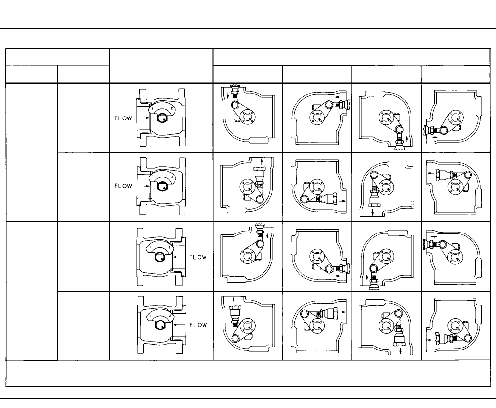
Instruction Manual
D101554X012
Vee-Ball Valves
January 2015
52
Figure 28. Index Marks for Actuator Lever Orientation for Non-Series B Valves
ACTUATOR
VALVE OPEN
ACTUATOR POSITION
MOUNTING STYLE 123 4
RIGHT-
HAND(1)
STYLE A
STYLE B
STYLE C
STYLE D
LEFT-
HAND(1)
(PDTC)(2)
(PDTO)(2)
(PDTC)(2)
(PDTO)(2)
(3)
1. Right-hand mounting controls with v notch no. 1; Left-hand mounting controls with v notch no. 2
2. PDTC-push down to close; PDTO-push down to open
3. Arrow on lever indicates direction of actuator thrust to close valve
B2703
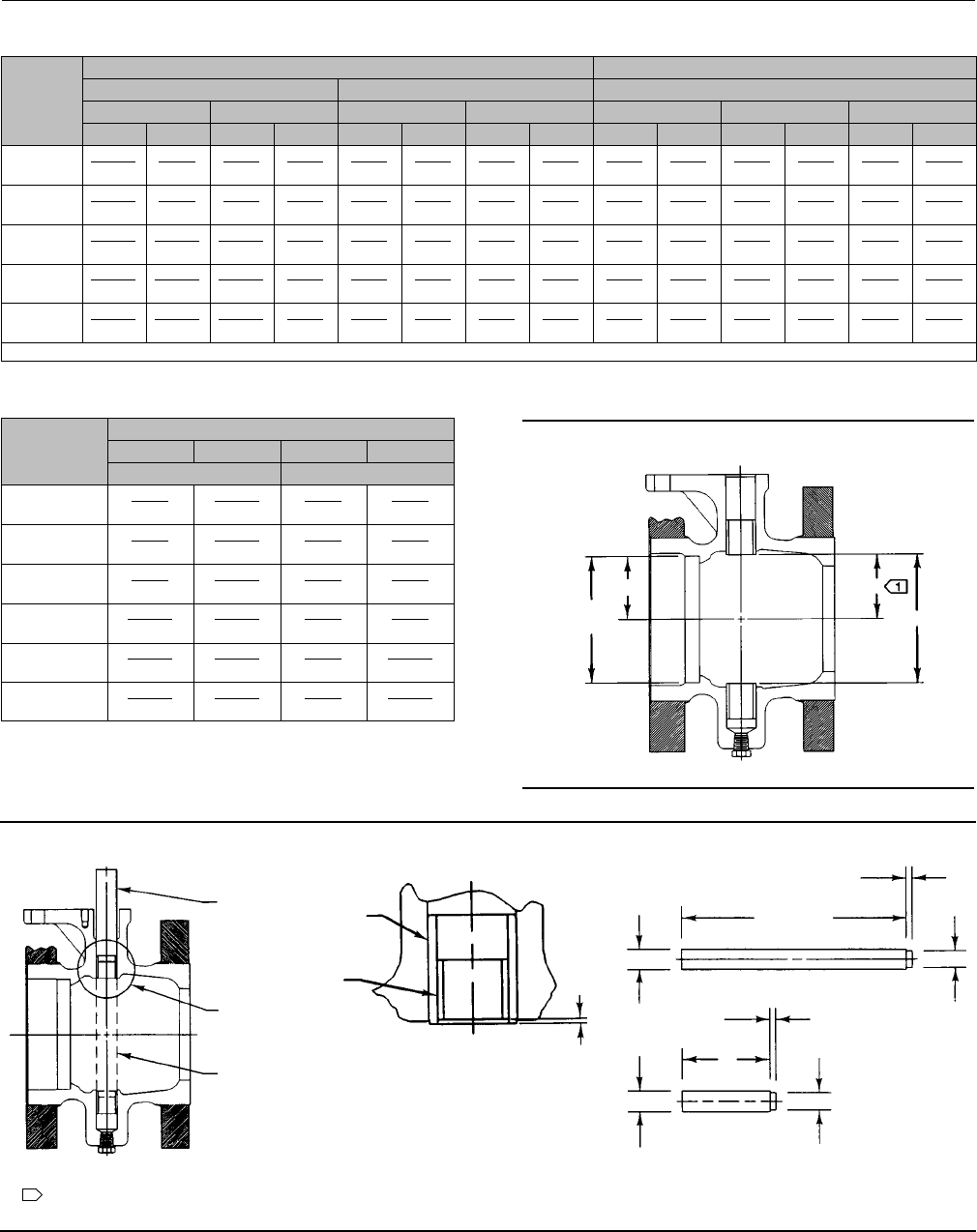
Instruction Manual
D101554X012
Vee-Ball Valves
January 2015
53
VALVE
SIZE,
NPS
BEARING RAM DIMENSIONS BUSHING RAM DIMENSIONS
Ram Lengths Ram Diameters Ram Diameters
L M D d D Long Ram d Short Ram d
mm Inches mm Inches mm Inches mm Inches mm Inches mm Inches mm Inches
3&4 201.42
MIN
7.930
MIN(1)
95.25
MIN
3.750
MIN
22.86
22.61
0.900
0.890
19.05
18.80
0.750
0.740
28.19
27.94
1.110
1.100
19.05
18.80
0.750
0.740
22.86
22.61
0.900
0.890
6247.65
MIN
9.750
MIN
95.25
MIN
3.750
MIN
29.21
28.96
1.150
1.140
25.40
25.15
1.000
0.990
34.54
34.29
1.360
1.350
25.40
25.15
1.000
0.990
29.21
28.96
1.150
1.140
8338.75
MIN
13.310
MIN
139.70
MIN
5.500
MIN
35.56
35.31
1.400
1.390
31.75
31.50
1.250
1.240
40.89
40.64
1.610
1.600
31.75
31.50
1.250
1.240
35.56
35.31
1.400
1.390
10 396.75
MIN
15.620
MIN
139.70
MIN
5.500
MIN
35.56
35.31
1.400
1.390
31.75
31.50
1.250
1.240
40.89
40.64
1.610
1.600
31.75
31.50
1.250
1.240
35.56
35.31
1.400
1.390
12 476.25
MIN
18.750
MIN
152.40
MIN
6.000
MIN
41.91
41.66
1.650
1.640
38.10
37.85
1.500
1.490
50.42
50.17
1.985
1.975
38.10
37.85
1.500
1.490
41.91
41.66
1.650
1.640
1. MIN = Minimum.
VALVE
SIZE,
NPS
DIMENSION
B C B C
Millimeters Inches
348.26
50.04
100.38
100.63
1.960
1.970
3.952
3.962
460.10
60.35
121.01
121.26
2.366
2.376
4.764
4.774
683.59
83.85
168.00
168.25
3.291
3.301
6.614
6.624
8106.20
106.45
213.21
213.46
4.181
4.191
8.394
8.404
10 135.33
135.59
271.48
271.73
5.328
5.338
10.688
10.698
12 169.67
169.93
340.16
340.41
6.680
6.690
13.392
13.402
Figure 29. Bushing Location
DIA A
A/2 B
C
BUSHING (KEY 5) LOCATION
A5684-1
Figure 30. Metal Bearing Ram Location
NPS 3 THRU 12
VIEW A
SHORT
RAM
SEE VIEW A
LONG
RAM
BUSHING
(KEY 5 OR 8)
BEARING
(KEY 10)
1.52
0.000
(0.060
0.000)
D
M
LONG RAM
SHORT RAM
D
L
6.35
(0.25)
d
d
mm
(INCHES)
BEARING RAM
NOTES:
DIMENSION B IS THE DISTANCE BETWEEN THE
GUIDE BUSHING AND THE CENTER OF DIAMETER A.
1
A5683-2
6.35
(0.25)
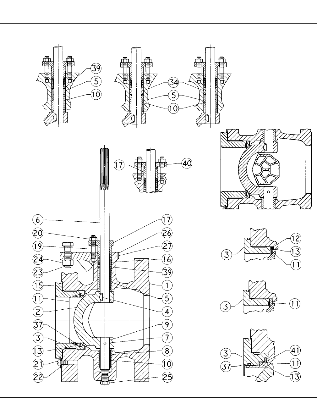
Instruction Manual
D101554X012
Vee-Ball Valves
January 2015
54
Figure 31. Fisher V150 and V300 Non-Series B Valve Assembly (NPS 3- 12)
(Details are typical for V200 Valves except V200 does not have flanges)
METAL BEARING
NPS 3-6 PEEK BEARING
NPS 8, 10, & 12
METAL
BEARING
NPS 8, 10 & 12
ALLOY ASSEMBLY
ATTENUATOR BALL
NPS 4-12
FLAT METAL SEAL
TCM SEAL
HD METAL SEAL
NPS 10 & 12
NOTE:
KEYS 28, 30, 31, 32, 35, AND 36 ARE NOT SHOWN.
42B4652-C

Instruction Manual
D101554X012
Vee-Ball Valves
January 2015
55

Instruction Manual
D101554X012
Vee-Ball Valves
January 2015
56
Emerson Process Management
Marshalltown, Iowa 50158 USA
Sorocaba, 18087 Brazil
Chatham, Kent ME4 4QZ UK
Dubai, United Arab Emirates
Singapore 128461 Singapore
www.Fisher.com
The contents of this publication are presented for informational purposes only, and while every effort has been made to ensure their accuracy, they arenot
to be construed as warranties or guarantees, express or implied, regarding the products or services described herein or their use or applicability. All sales are
governed by our terms and conditions, which are available upon request. We reserve the right to modify or improve the designs or specifications of such
products at any time without notice.
E1990, 2015 Fisher Controls International LLC. All rights reserved.
Fisher, ENVIRO-SEAL, Vee-Ball, and FIELDVUE are marks owned by one of the companies in the Emerson Process Management business unit of Emerson
Electric Co. Emerson Process Management, Emerson, and the Emerson logo are trademarks and service marks of Emerson Electric Co. All other marks are
the property of their respective owners.
Neither Emerson, Emerson Process Management, nor any of their affiliated entities assumes responsibility for the selection, use or maintenance
of any product. Responsibility for proper selection, use, and maintenance of any product remains solely with the purchaser and end user.
