Emerson H200 Series Relief Valves Data Sheet
2015-03-30
: Emerson Emerson-H200-Series-Relief-Valves-Data-Sheet-681284 emerson-h200-series-relief-valves-data-sheet-681284 emerson pdf
Open the PDF directly: View PDF ![]() .
.
Page Count: 4
Bulletin 71.4:H200
December 2009
D100165X012
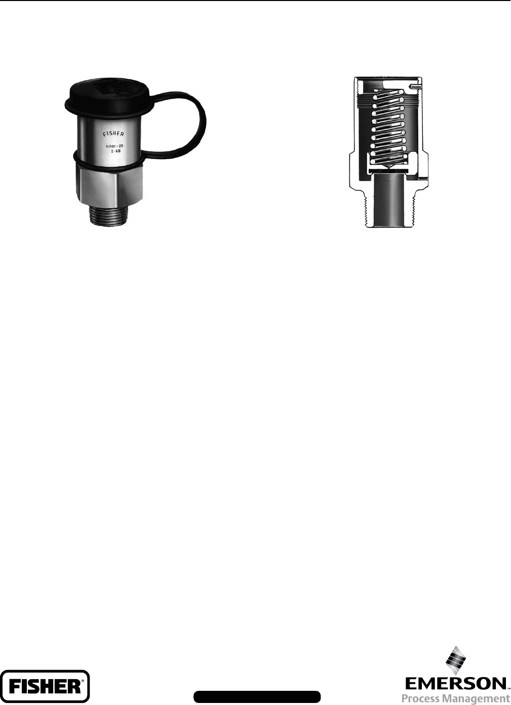
The H200 Series Pop™ relief valves, Figures 1 and 2,
are self-operated relief valves with preset and pinned
spring retainers. The inlet pressure registers directly
on a spring-opposed poppet assembly which includes
a Nitrile (NBR) disk. When the inlet gas pressure
increases above the spring setting, the poppet and disk
assembly is pushed away from the orifice. Springs
are available that provide any relief pressure setting
from 25 to 300 psig (1,7 to 20,7 bar).
With this simple operation and wide spring setting
selection, the H200 Series Pop relief valves may be
used where venting to atmosphere is acceptable,
where the process gas is compatible with the
Nitrile (NBR) disk, where its relief capacity is
adequate, and where some pressure relieving
tolerance is acceptable. Common applications
include use on pneumatic control lines of air drills,
jackhammers and other similar equipment, and on
farm tap installations. The H200 Series is comprised
of the Types H202 and H203 relief valves with the
difference being in the inlet connection size.
Small relief valve
size allows installation where space is limited.
Low initial cost, easy installation,
and high capacity per dollar invested reduces
total cost of having relief valve capabilities in
your system.
Brass body construction and stainless
steel spring reduces susceptibility to corrosion
damage and the preset, pinned spring retainer
prevents relief valve setpoint tampering.
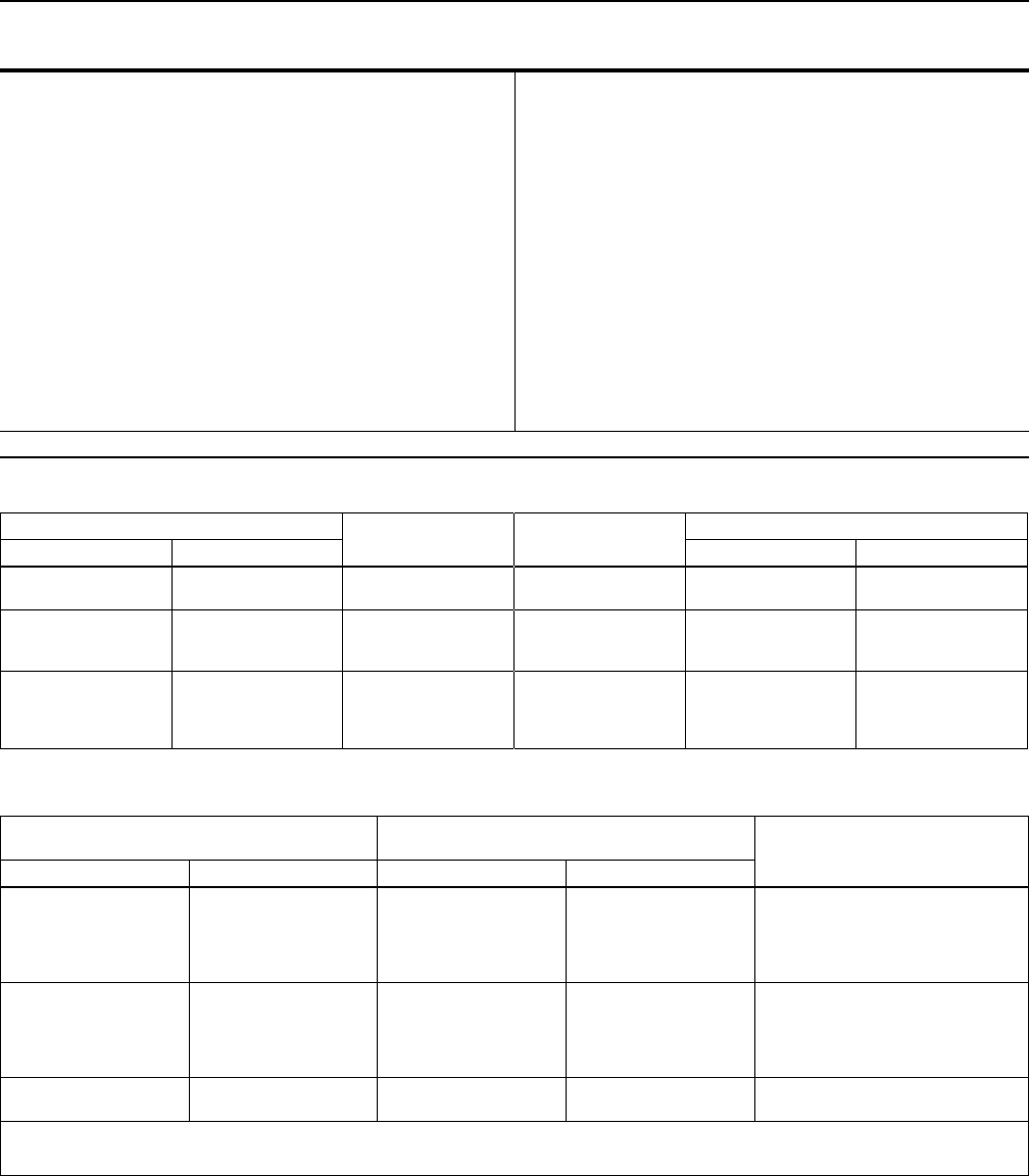
This relief valve may be installed in any position but
must be oriented so that gas discharged from the
valve does not create a re, toxic, or explosion hazard.
The relief valve should be protected from material and
conditions that could clog the outlet side of the valve
and affect the venting of gas.
A typical installation is shown in Figure 3. A Type P145
raincap is recommended for use with any H200 Series
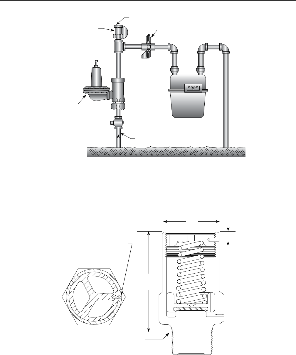
relief valve. Dimensions are shown in Figure 4.
The relief valve and installation should be checked for
compliance with all applicable codes.
Figure 1. External View of H200 Series Relief Valve
W1929–1
Figure 2. Sectional View of H200 Series Relief Valve
W0120–1
Bulletin 71.4:H200
2
3/4 NPT connection
1 NPT connection
400 psig (27,6 bar)
See Tables 1 and 2
See Table 2
405
Brass
Nitrile (NBR)
302 Stainless Steel
-20° to 160°F (-29° to 71°C)
0.5 pounds (0,2 kg)
Type P145 raincap
1. The pressure/temperature limits in this Bulletin or any applicable code limitations should not be exceeded.
Table 1. Relief Pressure Spring Ranges
25 to 30
31 to 55
1,7 to 2,1
2,1 to 3,8
1H485637022
1J152137022
Pink
White ±5 ±0,34
56 to 75
65 to 95
90 to 130
3,9 to 5,2
4,5 to 6,5
6,2 to 9,0
1P391137022
T1049037022
1F791337022
Blue
Plain
Purple
±8 ±0,55
131 to 160
161 to 190
191 to 235
236 to 300
9,0 to 11,0
11,1 to 13,1
13,2 to 16,2
16,3 to 20,7
1F7912T0012
T12699T0012
1F790937022
1E954637052
Yellow
Green
Brown
Plain
±15 ±1,03
Table 2. Relief Set Pressures and Capacities
25
50
75
100
125
1,7
3,4
5,2
6,9
8,6
50
75
100
120
150
3,4
5,2
6,9
8,3
10,3
34 200 (916)
47 400 (1270)
60 000 (1608)
69 600 (1865)
83 400 (2235)
150
175
200
225
250
10,3
12,1
13,8
15,5
17,2
180
210
240
270
300
12,4
14,5
16,5
18,6
20,7
100 500 (2693)
117 600 (3152)
132 000 (3538)
150 000 (4020)
165 000 (4422)
275
300
19,0
20,7
330
360
22,7
24,8
180 000 (4824)
195 000 (5226)
1. This is the initial leak point, the point at which the relief valve begins to discharge.
2. 0.6 Specic Gravity Gas. To convert to equivalent capacities of other gases, multiply the table values by 0.775 for air or 0.789 for nitrogen. Multiply the ow obtained by 0.0268 to
convert to (Nm3/h) at 0°C and 1,01 bar.
When ordering an H200 Series relief valve, specify the
type number and the relief pressure setting required.
Bulletin 71.4:H200
3
Figure 3. Typical Farm Tap Installation
AF9930-C
A1619-1
Figure 4. Dimensions
AE8234

Bulletin 71.4:H200
The Emerson logo is a trademark and service mark of Emerson Electric Co. All other marks are the property of their prospective owners. Fisher is a mark owned by Fisher Controls, Inc., a
business of Emerson Process Management.
The contents of this publication are presented for informational purposes only, and while every effort has been made to ensure their accuracy, they are not to be construed as warranties or
guarantees, express or implied, regarding the products or services described herein or their use or applicability. We reserve the right to modify or improve the designs or specications of such
products at any time without notice.
Emerson Process Management does not assume responsibility for the selection, use or maintenance of any product. Responsibility for proper selection, use and maintenance of any Emerson
Process Management product remains solely with the purchaser.
©Emerson Process Management Regulator Technologies, Inc., 1979, 2009; All Rights Reserved
USA - Headquarters
McKinney, Texas 75069-1872 USA
Tel: 1-800-558-5853
Outside U.S. 1-972-548-3574
Asia-Pacic
Shanghai, China 201206
Tel: +86 21 2892 9000
Europe
Bologna, Italy 40013
Tel: +39 051 4190611
Middle East and Africa
Dubai, United Arab Emirates
Tel: +971 4811 8100
USA - Headquarters
McKinney, Texas 75069-1872 USA
Tel: 1-800-558-5853
Outside U.S. 1-972-548-3574
Asia-Pacic
Singapore, Singapore 128461
Tel: +65 6777 8211
Europe
Bologna, Italy 40013
Tel: +39 051 4190611
Gallardon, France 28320
Tel: +33 (0)2 37 33 47 00
USA - Headquarters
Elk River, Minnesota 55330-2445 USA
Tel: 1-763-241-3238
Europe
Selmsdorf, Germany 23923
Tel: +49 (0) 38823 31 0
For further information visit www.sherregulators.com
