Emerson Liebert Challenger Itr Brochure
ITR to the manual 24406072-7a2e-4b63-bbc0-cc683d98850f
2015-01-05
: Emerson Emerson-Liebert-Challenger-Itr-Brochure-165173 emerson-liebert-challenger-itr-brochure-165173 emerson pdf
Open the PDF directly: View PDF ![]() .
.
Page Count: 74
- Product Nomenclature
- 1.0 Dedicated, Precise Environmental Control
- 2.0 Precision Environmental Control for Industrial, Telecommunications, Medical and Data Processing Equipment
- 3.0 Local Monitoring Systems
- 4.0 Standard Features-All Systems
- 5.0 Chilled Water System-Standard and Optional Features
- 6.0 Refrigeration Systems
- 7.0 Air-Cooled System-Standard and Optional Features
- 8.0 Water/Glycol-Cooled Systems-Standard and Optional Features
- 9.0 GLYCOOL Systems-Standard and Optional Features
- 10.0 Optional Equipment-All Systems
- 11.0 Comprehensive Monitoring Systems-Optional
- 12.0 Comprehensive Monitoring Solutions-Optional
- 13.0 System Data
- Table 2 Liebert Challenger ITR air-cooled data-60 Hz
- Table 3 Liebert Challenger ITR air-cooled data-60 Hz (continued)
- Table 4 Liebert Challenger ITR air-cooled data-50 Hz
- Table 5 Liebert Challenger ITR air-cooled data-50Hz (continued)
- Table 6 Liebert Challenger ITR water cooled data, 60 Hz
- Table 7 Liebert Challenger ITR water cooled data, 60 Hz (continued)
- Table 8 Liebert Challenger ITR water cooled data, 50 Hz
- Table 9 Liebert Challenger ITR water cooled data, 50 Hz (continued)
- Table 10 Liebert Challenger ITR glycol cooled data, 60 Hz
- Table 11 Liebert Challenger ITR glycol cooled data, 60 Hz (continued)
- Table 12 Liebert Challenger ITR glycol cooled data, 50 Hz
- Table 13 Liebert Challenger ITR glycol cooled data, 50 Hz (continued)
- Table 14 Liebert Challenger ITR chilled water data, 60 Hz
- Table 15 Liebert Challenger ITR chilled water data, 50 Hz
- 14.0 Dimensional Drawings
- Figure 11 Cabinet and floor planning dimensional data-Horizontal flow models
- Figure 12 Cabinet and floor planning dimensional data
- Figure 13 Cabinet and floor planning dimensional data-Split system-5-ton centrifugal fan condensing unit
- Figure 14 Cabinet and floor planning dimensional data-Split system-5-ton water/glycol-cooled condensing unit
- Figure 15 Cabinet and floor planning dimensional data-Split System-Propeller fan condensing unit
- Figure 16 Cabinet and floor planning dimensional data-Propeller fan condensing modules-Vertical air discharge
- Figure 17 Cabinet and floor planning dimensional data-Self-contained system-Air-cooled condenser or drycooler
- 15.0 Electrical Data
- Table 16 Liebert Challenger ITR electrical data1-60 Hz
- Table 17 Self-contained with SCR reheat *
- Table 18 Scroll compressor and main fan (for comparison purposes only) *
- Table 19 Outdoor condensing units
- Table 20 Outdoor condensing units-Quiet-Line
- Table 21 Indoor condensing units, air-cooled *
- Table 22 Indoor condensing units, water-cooled *
- Table 23 Fan speed control condensers *
- Table 24 Liebert Lee-Temp condensers *
- Table 25 Liebert Lee-Temp receiver heater pads for use w/CSL condensers
- Table 26 Drycooler and pump package - 95˚F (35˚C) ambient *
- Table 27 Liebert Challenger ITR electrical data-50 Hz
- Table 28 Self-contained with SCR reheat
- Table 29 Scroll compressor and main fan (for comparison only)
- Table 30 Outdoor condensing units
- Table 31 Indoor condensing units air-cooled
- Table 32 Indoor condensing units water-cooled
- Table 33 Fan speed control condensers
- Table 34 Liebert Lee-Temp condensers
- Table 35 Liebert Lee-Temp receiver heater pads; for use w/CSL condensers
- Table 36 Drycooler only - 35˚C (95˚F) ambient, three-phase
- Table 37 Drycooler only - 35˚C (95˚F) ambient, single phase
- Table 38 Pumps
- Guide Specifications-Nominal 23 or 33kW Environmental Control System
- 1.0 General
- 2.0 Product
- 3.0 Execution
Precision Cooling
For Business-Critical Continuity™
Liebert® Challenger™ ITR
Technical Data Manual - Row-Based, Floor-Mounted Nominal 23 or 33kW Systems, Air-Cooled,
Water/Glycol-Cooled, GLYCOOL, Chilled Water, Split Systems, 50 & 60 Hz
PRODUCT NOMENCLATURE
NOTE
Tables i,ii and iii show nomenclature for the complete range of all available product options.
Not all combinations are possible. For assistance, contact your local dealer, Liebert
representative or call 1-800-543-2778.
Table i Product model information
B F 042 A — A A E I
Challenger
ITR
R = ITR,
Horizontal Flow
Nominal
capacity in
thousand
BTUH
A-=Air-Cooled A = 460/60/3 A = Advanced
Microprocessor
0 = No Reheat 0 = No
Humidifier
M = ITR,
Horizontal Flow
with Econ-O-Coil
C-= Chilled
Water
B = 575/60/3 G = Advanced
Microprocessor
w/Graphics
E = Electric
Reheat
I = Infrared
Humidifier
E- = Evaporator C = 208/60/3 H = Hot Water
Reheat
S = Steam
Generating
Humidifier
G-= GLYCOOL D = 230/60/3 G = Hot Gas
Reheat
WG = Water-
Cooled/Glycol-
cooled
2 = 380/60/3 S = SCR
Reheat
J = 200/50/3
H = 230/50/3
M = 380/415/50/3
Table ii Split system configurations
Evaporator
Condensing Units
Air-Cooled Prop Fan
Condensing Unit
Air-Cooled
Centrifugal
Condensing Unit
Water/Glycol
Condensing Unit
60 Hz
(50 Hz)
BR060E
(BR059E)
PFH067A_ _H3
PFH066A_ _H3
MC_65A
(MC_64A)
MC_69W
(MC_68W)
Table iii Self-contained system configurations
Frequency Indoor Unit
Remote Equipment
System Type
Air-Cooled
Condenser Drycooler/Pump
60 Hz (50 Hz) BR067A (BR065A) CS@104 Air-Cooled
60 Hz (50 Hz) BR071WG (BR070WG)
DSF112
3/4 HP Pump 60 Hz
1-1/2 HP Pump 50 Hz
Glycol-Cooled or Self-
Contained - Water-Cooled
60 Hz (50 Hz) BM061G (BM058G) DSO112
1-1/2 HP Pump GLYCOOL™
60 Hz (50 Hz) BR102C (BR101C) Self-Contained - Chilled
Water
@
F = Fan Speed Control
L = Lee Temp

i
TABLE OF CONTENTS
PRODUCT NOMENCLATURE . . . . . . . . . . . . . . . . . . . . . . . . . . . . . . . . . . . . . . INSIDE FRONT COVER
1.0 DEDICATED, PRECISE ENVIRONMENTAL CONTROL . . . . . . . . . . . . . . . . . . . . . . . . . . . . . . . .1
1.1 Temperature Control . . . . . . . . . . . . . . . . . . . . . . . . . . . . . . . . . . . . . . . . . . . . . . . . . . . . . . . . . 1
1.2 Humidity Control . . . . . . . . . . . . . . . . . . . . . . . . . . . . . . . . . . . . . . . . . . . . . . . . . . . . . . . . . . . . 1
1.3 Air Volume . . . . . . . . . . . . . . . . . . . . . . . . . . . . . . . . . . . . . . . . . . . . . . . . . . . . . . . . . . . . . . . . . 1
1.4 Air Filtration. . . . . . . . . . . . . . . . . . . . . . . . . . . . . . . . . . . . . . . . . . . . . . . . . . . . . . . . . . . . . . . . 1
1.5 Year Round Operation . . . . . . . . . . . . . . . . . . . . . . . . . . . . . . . . . . . . . . . . . . . . . . . . . . . . . . . . 1
1.6 Agency Listed . . . . . . . . . . . . . . . . . . . . . . . . . . . . . . . . . . . . . . . . . . . . . . . . . . . . . . . . . . . . . . . 1
2.0 PRECISION ENVIRONMENTAL CONTROL FOR INDUSTRIAL, TELECOMMUNICATIONS,
MEDICAL AND DATA PROCESSING EQUIPMENT . . . . . . . . . . . . . . . . . . . . . . . . . . . . . . . . . .2
2.1 Liebert Challenger ITR . . . . . . . . . . . . . . . . . . . . . . . . . . . . . . . . . . . . . . . . . . . . . . . . . . . . . . . 2
2.2 Multiple Configurations to Fit a Variety of Spaces . . . . . . . . . . . . . . . . . . . . . . . . . . . . . . . . . 2
2.3 Efficiency in Economic Terms . . . . . . . . . . . . . . . . . . . . . . . . . . . . . . . . . . . . . . . . . . . . . . . . . . 2
2.4 GLYCOOL. . . . . . . . . . . . . . . . . . . . . . . . . . . . . . . . . . . . . . . . . . . . . . . . . . . . . . . . . . . . . . . . . . 2
3.0 LOCAL MONITORING SYSTEMS . . . . . . . . . . . . . . . . . . . . . . . . . . . . . . . . . . . . . . . . . . . . . .5
3.1 Control. . . . . . . . . . . . . . . . . . . . . . . . . . . . . . . . . . . . . . . . . . . . . . . . . . . . . . . . . . . . . . . . . . . . . 5
3.2 Control Type . . . . . . . . . . . . . . . . . . . . . . . . . . . . . . . . . . . . . . . . . . . . . . . . . . . . . . . . . . . . . . . . 5
3.3 Internal System Control . . . . . . . . . . . . . . . . . . . . . . . . . . . . . . . . . . . . . . . . . . . . . . . . . . . . . . 5
3.4 Monitoring . . . . . . . . . . . . . . . . . . . . . . . . . . . . . . . . . . . . . . . . . . . . . . . . . . . . . . . . . . . . . . . . . 5
3.5 Diagnostics . . . . . . . . . . . . . . . . . . . . . . . . . . . . . . . . . . . . . . . . . . . . . . . . . . . . . . . . . . . . . . . . . 5
3.6 Logging . . . . . . . . . . . . . . . . . . . . . . . . . . . . . . . . . . . . . . . . . . . . . . . . . . . . . . . . . . . . . . . . . . . . 6
3.7 Alarms. . . . . . . . . . . . . . . . . . . . . . . . . . . . . . . . . . . . . . . . . . . . . . . . . . . . . . . . . . . . . . . . . . . . . 6
3.8 Graphical Displays—Advanced Graphic Control Only . . . . . . . . . . . . . . . . . . . . . . . . . . . . . . 6
4.0 STANDARD FEATURES—ALL SYSTEMS . . . . . . . . . . . . . . . . . . . . . . . . . . . . . . . . . . . . . . . .7
4.1 Cabinet and Frame. . . . . . . . . . . . . . . . . . . . . . . . . . . . . . . . . . . . . . . . . . . . . . . . . . . . . . . . . . . 7
4.2 Electrical Panel. . . . . . . . . . . . . . . . . . . . . . . . . . . . . . . . . . . . . . . . . . . . . . . . . . . . . . . . . . . . . . 7
4.3 Fan Section . . . . . . . . . . . . . . . . . . . . . . . . . . . . . . . . . . . . . . . . . . . . . . . . . . . . . . . . . . . . . . . . . 7
4.4 Infrared Humidifier . . . . . . . . . . . . . . . . . . . . . . . . . . . . . . . . . . . . . . . . . . . . . . . . . . . . . . . . . . 7
4.5 Electric Reheat . . . . . . . . . . . . . . . . . . . . . . . . . . . . . . . . . . . . . . . . . . . . . . . . . . . . . . . . . . . . . . 7
4.6 Filters . . . . . . . . . . . . . . . . . . . . . . . . . . . . . . . . . . . . . . . . . . . . . . . . . . . . . . . . . . . . . . . . . . . . . 7
4.6.1 Condensate Pump. . . . . . . . . . . . . . . . . . . . . . . . . . . . . . . . . . . . . . . . . . . . . . . . . . . . . . . . . . . . . 8
4.6.2 Remote Temperature/ Humidity Sensors . . . . . . . . . . . . . . . . . . . . . . . . . . . . . . . . . . . . . . . . . . 8
4.6.3 Disconnect Switch—Locking Type. . . . . . . . . . . . . . . . . . . . . . . . . . . . . . . . . . . . . . . . . . . . . . . . 8
5.0 CHILLED WATER SYSTEM—STANDARD AND OPTIONAL FEATURES . . . . . . . . . . . . . . . . . . .9
5.1 Chilled Water System—Standard Features . . . . . . . . . . . . . . . . . . . . . . . . . . . . . . . . . . . . . . . 9
5.1.1 Cooling Coil. . . . . . . . . . . . . . . . . . . . . . . . . . . . . . . . . . . . . . . . . . . . . . . . . . . . . . . . . . . . . . . . . . 9
5.1.2 Modulating Motor . . . . . . . . . . . . . . . . . . . . . . . . . . . . . . . . . . . . . . . . . . . . . . . . . . . . . . . . . . . . . 9
5.1.3 Line Insulation . . . . . . . . . . . . . . . . . . . . . . . . . . . . . . . . . . . . . . . . . . . . . . . . . . . . . . . . . . . . . . . 9
5.1.4 Three-Way Control Valve. . . . . . . . . . . . . . . . . . . . . . . . . . . . . . . . . . . . . . . . . . . . . . . . . . . . . . . 9

ii
5.2 Chilled Water System—Optional Features . . . . . . . . . . . . . . . . . . . . . . . . . . . . . . . . . . . . . . . 9
5.2.1 Chilled Water Flow Switch . . . . . . . . . . . . . . . . . . . . . . . . . . . . . . . . . . . . . . . . . . . . . . . . . . . . . 9
5.2.2 High Pressure . . . . . . . . . . . . . . . . . . . . . . . . . . . . . . . . . . . . . . . . . . . . . . . . . . . . . . . . . . . . . . . . 9
6.0 REFRIGERATION SYSTEMS . . . . . . . . . . . . . . . . . . . . . . . . . . . . . . . . . . . . . . . . . . . . . . . .10
6.1 Self-Contained Systems . . . . . . . . . . . . . . . . . . . . . . . . . . . . . . . . . . . . . . . . . . . . . . . . . . . . . . 10
6.2 Split Systems . . . . . . . . . . . . . . . . . . . . . . . . . . . . . . . . . . . . . . . . . . . . . . . . . . . . . . . . . . . . . . 10
6.3 Refrigeration System Components—Standard Features. . . . . . . . . . . . . . . . . . . . . . . . . . . . 10
6.3.1 Compressor . . . . . . . . . . . . . . . . . . . . . . . . . . . . . . . . . . . . . . . . . . . . . . . . . . . . . . . . . . . . . . . . . 10
6.3.2 Evaporator Coil. . . . . . . . . . . . . . . . . . . . . . . . . . . . . . . . . . . . . . . . . . . . . . . . . . . . . . . . . . . . . . 10
6.3.3 Safety Control . . . . . . . . . . . . . . . . . . . . . . . . . . . . . . . . . . . . . . . . . . . . . . . . . . . . . . . . . . . . . . . 10
6.3.4 Expansion Valve . . . . . . . . . . . . . . . . . . . . . . . . . . . . . . . . . . . . . . . . . . . . . . . . . . . . . . . . . . . . . 10
7.0 AIR-COOLED SYSTEM—STANDARD AND OPTIONAL FEATURES . . . . . . . . . . . . . . . . . . . . . 11
7.1 Air-Cooled, Self-Contained Systems—Standard Features. . . . . . . . . . . . . . . . . . . . . . . . . . . 11
7.1.1 Pump Down Control . . . . . . . . . . . . . . . . . . . . . . . . . . . . . . . . . . . . . . . . . . . . . . . . . . . . . . . . . . 11
7.1.2 Condenser . . . . . . . . . . . . . . . . . . . . . . . . . . . . . . . . . . . . . . . . . . . . . . . . . . . . . . . . . . . . . . . . . . 11
7.1.3 Fan Speed Control . . . . . . . . . . . . . . . . . . . . . . . . . . . . . . . . . . . . . . . . . . . . . . . . . . . . . . . . . . . 11
7.2 Air-Cooled, Self-Contained Systems—Optional Features . . . . . . . . . . . . . . . . . . . . . . . . . . . 11
7.2.1 Liebert Lee-Temp Winter Control Condenser . . . . . . . . . . . . . . . . . . . . . . . . . . . . . . . . . . . . . 11
7.2.2 Quiet-Line Condensers. . . . . . . . . . . . . . . . . . . . . . . . . . . . . . . . . . . . . . . . . . . . . . . . . . . . . . . . 11
7.3 Air-Cooled Split Systems—Standard Features . . . . . . . . . . . . . . . . . . . . . . . . . . . . . . . . . . . 12
7.3.1 Centrifugal Fan, Condensing Unit . . . . . . . . . . . . . . . . . . . . . . . . . . . . . . . . . . . . . . . . . . . . . . 12
7.3.2 Propeller Fan Condensing Unit . . . . . . . . . . . . . . . . . . . . . . . . . . . . . . . . . . . . . . . . . . . . . . . . . 12
7.3.3 Propeller Fan Condensing Unit Options . . . . . . . . . . . . . . . . . . . . . . . . . . . . . . . . . . . . . . . . . . 12
7.4 Air-Cooled Split Systems—Optional Features . . . . . . . . . . . . . . . . . . . . . . . . . . . . . . . . . . . . 12
8.0 WATER/GLYCOL-COOLED SYSTEMS—STANDARD AND OPTIONAL FEATURES . . . . . . . . . . .13
8.1 Water/Glycol Self-Contained Systems—Standard Features . . . . . . . . . . . . . . . . . . . . . . . . . 13
8.2 Water/Glycol-Cooled, Self-Contained System—Optional Features. . . . . . . . . . . . . . . . . . . . 13
8.3 Water/Glycol Split System—Standard Features . . . . . . . . . . . . . . . . . . . . . . . . . . . . . . . . . . 13
8.4 Water/Glycol-Cooled, Split System—Optional Features . . . . . . . . . . . . . . . . . . . . . . . . . . . . 14
8.4.1 Glycol-Cooled System—Heat Rejection Devices . . . . . . . . . . . . . . . . . . . . . . . . . . . . . . . . . . . . 14
8.4.2 Self-Contained and Split Systems . . . . . . . . . . . . . . . . . . . . . . . . . . . . . . . . . . . . . . . . . . . . . . . 14
9.0 GLYCOOL SYSTEMS—STANDARD AND OPTIONAL FEATURES . . . . . . . . . . . . . . . . . . . . .15
9.1 GLYCOOL—Self-Contained Models Only . . . . . . . . . . . . . . . . . . . . . . . . . . . . . . . . . . . . . . . 15
9.2 GLYCOOL System—Standard Features . . . . . . . . . . . . . . . . . . . . . . . . . . . . . . . . . . . . . . . . 15
9.2.1 Comparative Temperature Monitor . . . . . . . . . . . . . . . . . . . . . . . . . . . . . . . . . . . . . . . . . . . . . 15
9.2.2 Econ-O-Coil . . . . . . . . . . . . . . . . . . . . . . . . . . . . . . . . . . . . . . . . . . . . . . . . . . . . . . . . . . . . . . . . . 15
9.2.3 GLYCOOL Three-Way Control Valve . . . . . . . . . . . . . . . . . . . . . . . . . . . . . . . . . . . . . . . . . . . . 15
9.2.4 Glycol-Regulating Valve. . . . . . . . . . . . . . . . . . . . . . . . . . . . . . . . . . . . . . . . . . . . . . . . . . . . . . . 15
9.2.5 Drycooler . . . . . . . . . . . . . . . . . . . . . . . . . . . . . . . . . . . . . . . . . . . . . . . . . . . . . . . . . . . . . . . . . . . 16
9.3 Glycol and GLYCOOL-Cooled—Optional Equipment . . . . . . . . . . . . . . . . . . . . . . . . . . . . . . 16
10.0 OPTIONAL EQUIPMENT—ALL SYSTEMS. . . . . . . . . . . . . . . . . . . . . . . . . . . . . . . . . . . . . . .17
10.1 Steam Generating Humidifier . . . . . . . . . . . . . . . . . . . . . . . . . . . . . . . . . . . . . . . . . . . . . . . . . 17
10.2 Adjustable Floor Stand . . . . . . . . . . . . . . . . . . . . . . . . . . . . . . . . . . . . . . . . . . . . . . . . . . . . . . 17

iii
10.3 SCR Reheat. . . . . . . . . . . . . . . . . . . . . . . . . . . . . . . . . . . . . . . . . . . . . . . . . . . . . . . . . . . . . . . . 18
10.4 High-Efficiency Filter. . . . . . . . . . . . . . . . . . . . . . . . . . . . . . . . . . . . . . . . . . . . . . . . . . . . . . . . 18
10.5 High External Static Blowers . . . . . . . . . . . . . . . . . . . . . . . . . . . . . . . . . . . . . . . . . . . . . . . . . 18
10.6 High-Efficiency Motors. . . . . . . . . . . . . . . . . . . . . . . . . . . . . . . . . . . . . . . . . . . . . . . . . . . . . . . 18
10.7 Plenums . . . . . . . . . . . . . . . . . . . . . . . . . . . . . . . . . . . . . . . . . . . . . . . . . . . . . . . . . . . . . . . . . . 18
10.8 Low-Profile Plenum with Cold-Aisle Discharge . . . . . . . . . . . . . . . . . . . . . . . . . . . . . . . . . . . 18
10.9 Smoke Detector. . . . . . . . . . . . . . . . . . . . . . . . . . . . . . . . . . . . . . . . . . . . . . . . . . . . . . . . . . . . . 19
10.10 Firestat . . . . . . . . . . . . . . . . . . . . . . . . . . . . . . . . . . . . . . . . . . . . . . . . . . . . . . . . . . . . . . . . . . . 19
10.11 Hot Water Reheat. . . . . . . . . . . . . . . . . . . . . . . . . . . . . . . . . . . . . . . . . . . . . . . . . . . . . . . . . . . 19
11.0 COMPREHENSIVE MONITORING SYSTEMS—OPTIONAL . . . . . . . . . . . . . . . . . . . . . . . . . . . .20
11.1 Enterprise Monitoring Systems. . . . . . . . . . . . . . . . . . . . . . . . . . . . . . . . . . . . . . . . . . . . . . . . 20
11.2 Network Monitoring Systems . . . . . . . . . . . . . . . . . . . . . . . . . . . . . . . . . . . . . . . . . . . . . . . . . 20
11.3 Stand-Alone Monitoring and Leak Detection Solutions. . . . . . . . . . . . . . . . . . . . . . . . . . . . . 20
12.0 COMPREHENSIVE MONITORING SOLUTIONS—OPTIONAL . . . . . . . . . . . . . . . . . . . . . . . . . .22
12.1 Liebert SiteScan® Web. . . . . . . . . . . . . . . . . . . . . . . . . . . . . . . . . . . . . . . . . . . . . . . . . . . . . . . 22
12.2 Liebert SiteLink . . . . . . . . . . . . . . . . . . . . . . . . . . . . . . . . . . . . . . . . . . . . . . . . . . . . . . . . . . . . 22
12.3 Liebert Nform . . . . . . . . . . . . . . . . . . . . . . . . . . . . . . . . . . . . . . . . . . . . . . . . . . . . . . . . . . . . . . 22
12.4 Liebert IntelliSlot Web/485 Card With Adapter and Liebert IntelliSlot 485 Card
With Adapter . . . . . . . . . . . . . . . . . . . . . . . . . . . . . . . . . . . . . . . . . . . . . . . . . . . . . . . . . . . . . . 22
12.5 Environmental Discrete Outputs Card . . . . . . . . . . . . . . . . . . . . . . . . . . . . . . . . . . . . . . . . . . 22
12.6 Remote Contact Monitor (RCM4) . . . . . . . . . . . . . . . . . . . . . . . . . . . . . . . . . . . . . . . . . . . . . . 22
12.7 Auto-Changeover Control . . . . . . . . . . . . . . . . . . . . . . . . . . . . . . . . . . . . . . . . . . . . . . . . . . . . 22
12.8 Universal Monitor . . . . . . . . . . . . . . . . . . . . . . . . . . . . . . . . . . . . . . . . . . . . . . . . . . . . . . . . . . 23
12.8.1 Leak Detection . . . . . . . . . . . . . . . . . . . . . . . . . . . . . . . . . . . . . . . . . . . . . . . . . . . . . . . . . . . . . . 23
12.8.2 Temperature and Humidity Recorder . . . . . . . . . . . . . . . . . . . . . . . . . . . . . . . . . . . . . . . . . . . . 23
13.0 SYSTEM DATA . . . . . . . . . . . . . . . . . . . . . . . . . . . . . . . . . . . . . . . . . . . . . . . . . . . . . . . . .24
14.0 DIMENSIONAL DRAWINGS . . . . . . . . . . . . . . . . . . . . . . . . . . . . . . . . . . . . . . . . . . . . . . . . .38
15.0 ELECTRICAL DATA . . . . . . . . . . . . . . . . . . . . . . . . . . . . . . . . . . . . . . . . . . . . . . . . . . . . . .43
GUIDE SPECIFICATIONS—NOMINAL 23 OR 33KW ENVIRONMENTAL CONTROL
SYSTEM . . . . . . . . . . . . . . . . . . . . . . . . . . . . . . . . . . . . . . . . . . . . . . . . . . . . INSIDE FRONT COVER

iv
FIGURES
Figure 1 Unit configurations . . . . . . . . . . . . . . . . . . . . . . . . . . . . . . . . . . . . . . . . . . . . . . . . . . . . . . . . . . . . . . . 3
Figure 2 Unit configurations, continued. . . . . . . . . . . . . . . . . . . . . . . . . . . . . . . . . . . . . . . . . . . . . . . . . . . . . . 4
Figure 3 Microprocessor control systems . . . . . . . . . . . . . . . . . . . . . . . . . . . . . . . . . . . . . . . . . . . . . . . . . . . . . 6
Figure 4 Optional Views With Advanced Graphics . . . . . . . . . . . . . . . . . . . . . . . . . . . . . . . . . . . . . . . . . . . . . 6
Figure 5 Air-cooled condenser with Liebert Lee-Temp . . . . . . . . . . . . . . . . . . . . . . . . . . . . . . . . . . . . . . . . . 11
Figure 6 Outdoor propeller fan condensing unit . . . . . . . . . . . . . . . . . . . . . . . . . . . . . . . . . . . . . . . . . . . . . . 12
Figure 7 Liebert Challenger ITR unit core . . . . . . . . . . . . . . . . . . . . . . . . . . . . . . . . . . . . . . . . . . . . . . . . . . . 16
Figure 8 Steam generating humidifier . . . . . . . . . . . . . . . . . . . . . . . . . . . . . . . . . . . . . . . . . . . . . . . . . . . . . . 17
Figure 9 Adjustable floor stand. . . . . . . . . . . . . . . . . . . . . . . . . . . . . . . . . . . . . . . . . . . . . . . . . . . . . . . . . . . . 17
Figure 10 Monitoring configurations . . . . . . . . . . . . . . . . . . . . . . . . . . . . . . . . . . . . . . . . . . . . . . . . . . . . . . . . 21
Figure 11 Cabinet and floor planning dimensional data—Horizontal flow models . . . . . . . . . . . . . . . . . . . . 38
Figure 12 Cabinet and floor planning dimensional data . . . . . . . . . . . . . . . . . . . . . . . . . . . . . . . . . . . . . . . . . 39
Figure 13 Cabinet and floor planning dimensional data—Split system—5-ton centrifugal fan
condensing unit . . . . . . . . . . . . . . . . . . . . . . . . . . . . . . . . . . . . . . . . . . . . . . . . . . . . . . . . . . . . . . . . 39
Figure 14 Cabinet and floor planning dimensional data—Split system—5-ton water/glycol-cooled
condensing unit . . . . . . . . . . . . . . . . . . . . . . . . . . . . . . . . . . . . . . . . . . . . . . . . . . . . . . . . . . . . . . . . 40
Figure 15 Cabinet and floor planning dimensional data—Split System—Propeller fan condensing
unit . . . . . . . . . . . . . . . . . . . . . . . . . . . . . . . . . . . . . . . . . . . . . . . . . . . . . . . . . . . . . . . . . . . . . . . . . . 41
Figure 16 Cabinet and floor planning dimensional data—Propeller fan condensing
modules—Vertical air discharge . . . . . . . . . . . . . . . . . . . . . . . . . . . . . . . . . . . . . . . . . . . . . . . . . . . 42
Figure 17 Cabinet and floor planning dimensional data—Self-contained system—Air-cooled
condenser or drycooler . . . . . . . . . . . . . . . . . . . . . . . . . . . . . . . . . . . . . . . . . . . . . . . . . . . . . . . . . . . 42
TABLES
Table 1 Condensate pump capacity. . . . . . . . . . . . . . . . . . . . . . . . . . . . . . . . . . . . . . . . . . . . . . . . . . . . . . . . . 8
Table 2 Liebert Challenger ITR air-cooled data—60 Hz . . . . . . . . . . . . . . . . . . . . . . . . . . . . . . . . . . . . . . . 24
Table 3 Liebert Challenger ITR air-cooled data—60 Hz (continued) . . . . . . . . . . . . . . . . . . . . . . . . . . . . . 25
Table 4 Liebert Challenger ITR air-cooled data—50 Hz . . . . . . . . . . . . . . . . . . . . . . . . . . . . . . . . . . . . . . . 26
Table 5 Liebert Challenger ITR air-cooled data—50Hz (continued) . . . . . . . . . . . . . . . . . . . . . . . . . . . . . . 27
Table 6 Liebert Challenger ITR water cooled data, 60 Hz. . . . . . . . . . . . . . . . . . . . . . . . . . . . . . . . . . . . . . 28
Table 7 Liebert Challenger ITR water cooled data, 60 Hz (continued) . . . . . . . . . . . . . . . . . . . . . . . . . . . . 29
Table 8 Liebert Challenger ITR water cooled data, 50 Hz. . . . . . . . . . . . . . . . . . . . . . . . . . . . . . . . . . . . . . 30
Table 9 Liebert Challenger ITR water cooled data, 50 Hz (continued). . . . . . . . . . . . . . . . . . . . . . . . . . . . 31
Table 10 Liebert Challenger ITR glycol cooled data, 60 Hz. . . . . . . . . . . . . . . . . . . . . . . . . . . . . . . . . . . . . . 32
Table 11 Liebert Challenger ITR glycol cooled data, 60 Hz (continued) . . . . . . . . . . . . . . . . . . . . . . . . . . . . 33
Table 12 Liebert Challenger ITR glycol cooled data, 50 Hz. . . . . . . . . . . . . . . . . . . . . . . . . . . . . . . . . . . . . . 34
Table 13 Liebert Challenger ITR glycol cooled data, 50 Hz (continued) . . . . . . . . . . . . . . . . . . . . . . . . . . . . 35
Table 14 Liebert Challenger ITR chilled water data, 60 Hz . . . . . . . . . . . . . . . . . . . . . . . . . . . . . . . . . . . . . 36
Table 15 Liebert Challenger ITR chilled water data, 50 Hz . . . . . . . . . . . . . . . . . . . . . . . . . . . . . . . . . . . . . 37
Table 16 Liebert Challenger ITR electrical data1—60 Hz . . . . . . . . . . . . . . . . . . . . . . . . . . . . . . . . . . . . . . . 43
Table 17 Self-contained with SCR reheat * . . . . . . . . . . . . . . . . . . . . . . . . . . . . . . . . . . . . . . . . . . . . . . . . . . 44
Table 18 Scroll compressor and main fan (for comparison purposes only) * . . . . . . . . . . . . . . . . . . . . . . . . 45
Table 19 Outdoor condensing units. . . . . . . . . . . . . . . . . . . . . . . . . . . . . . . . . . . . . . . . . . . . . . . . . . . . . . . . . 45
Table 20 Outdoor condensing units—Quiet-Line . . . . . . . . . . . . . . . . . . . . . . . . . . . . . . . . . . . . . . . . . . . . . . 46
Table 21 Indoor condensing units, air-cooled *. . . . . . . . . . . . . . . . . . . . . . . . . . . . . . . . . . . . . . . . . . . . . . . . 46
Table 22 Indoor condensing units, water-cooled * . . . . . . . . . . . . . . . . . . . . . . . . . . . . . . . . . . . . . . . . . . . . . 46
Table 23 Fan speed control condensers * . . . . . . . . . . . . . . . . . . . . . . . . . . . . . . . . . . . . . . . . . . . . . . . . . . . . 47
Table 24 Liebert Lee-Temp condensers * . . . . . . . . . . . . . . . . . . . . . . . . . . . . . . . . . . . . . . . . . . . . . . . . . . . . 47
Table 25 Liebert Lee-Temp receiver heater pads for use w/CSL condensers . . . . . . . . . . . . . . . . . . . . . . . . 47

v
Table 26 Drycooler and pump package - 95°F (35°C) ambient * . . . . . . . . . . . . . . . . . . . . . . . . . . . . . . . . . . 47
Table 27 Liebert Challenger ITR electrical data—50 Hz. . . . . . . . . . . . . . . . . . . . . . . . . . . . . . . . . . . . . . . . 48
Table 28 Scroll compressor and main fan (for comparison only) . . . . . . . . . . . . . . . . . . . . . . . . . . . . . . . . . . 49
Table 29 Self-contained with SCR reheat . . . . . . . . . . . . . . . . . . . . . . . . . . . . . . . . . . . . . . . . . . . . . . . . . . . . 49
Table 30 Outdoor condensing units. . . . . . . . . . . . . . . . . . . . . . . . . . . . . . . . . . . . . . . . . . . . . . . . . . . . . . . . . 50
Table 31 Indoor condensing units air-cooled . . . . . . . . . . . . . . . . . . . . . . . . . . . . . . . . . . . . . . . . . . . . . . . . . 50
Table 32 Indoor condensing units water-cooled . . . . . . . . . . . . . . . . . . . . . . . . . . . . . . . . . . . . . . . . . . . . . . . 50
Table 33 Fan speed control condensers. . . . . . . . . . . . . . . . . . . . . . . . . . . . . . . . . . . . . . . . . . . . . . . . . . . . . . 50
Table 34 Liebert Lee-Temp condensers . . . . . . . . . . . . . . . . . . . . . . . . . . . . . . . . . . . . . . . . . . . . . . . . . . . . . 50
Table 35 Liebert Lee-Temp receiver heater pads; for use w/CSL condensers . . . . . . . . . . . . . . . . . . . . . . . 50
Table 36 Drycooler only - 35°C (95°F) ambient, three-phase. . . . . . . . . . . . . . . . . . . . . . . . . . . . . . . . . . . . . 51
Table 37 Drycooler only - 35°C (95°F) ambient, single phase . . . . . . . . . . . . . . . . . . . . . . . . . . . . . . . . . . . . 51
Table 38 Pumps . . . . . . . . . . . . . . . . . . . . . . . . . . . . . . . . . . . . . . . . . . . . . . . . . . . . . . . . . . . . . . . . . . . . . . . . 51

vi

Dedicated, Precise Environmental Control
1
1.0 DEDICATED, PRECISE ENVIRONMENTAL CONTROL
For sensitive electronics, environmental control is more than simple cooling. “Comfort” air condition-
ing systems are designed for the comfort of people and simply cannot provide the kind of environment
required by high performance computer or communication equipment.
1.1 Temperature Control
The high density heat load in a computer room or other similar application is beyond the capacity of
ordinary air conditioning systems.
Sensitive electronics are best maintained in a stable environment of 72°F ±2°F (22.2°C ±1°C). Because
computers and communications equipment generate large quantities of heat in small areas, six to 10
times the heat density of normal office space, the air conditioning system must have more than just
enough cooling capacity. It must have the precision to react quickly to a drastic change in heat load
and prevent wide temperature fluctuations—something a large building system cannot do.
1.2 Humidity Control
The electronic equipment must be protected from both internal condensation and static electricity dis-
charges.
Maintaining the correct humidity level in the room is just as important as maintaining proper tem-
perature. When humidity is too high, condensation may form inside electronic equipment and damage
it. If humidity is too low, static electricity could disrupt operation or even shut down the electronic
system. An ordinary building system cannot normally control the environment within these boundar-
ies.
1.3 Air Volume
Computers and other sensitive electronics require greater air volumes than ordinary air conditioning
can provide. Typical comfort systems are designed to provide between 300 and 400 CFM (cubic feet
per minute), (500–700 CMH) per ton of cooling. Computer systems require between 500 and 600 CFM
(850–1020 CMH) per ton. The high density heat load in a relatively small space requires more
changes of air than a less dense “comfort” application.
While a normal office space requires only two air changes per hour, a room filled with electronic
equipment requires up to 30 changes per hour. Without proper air volume, hot spots and temperature
fluctuations could develop within the room. Also, greater air volumes provide the higher sensible heat
ratios required by electronic computer equipment.
1.4 Air Filtration
A clean environment of properly filtered air is essential. Build-up of dust and fibers attracted by oper-
ating electronics can cause faults and impair the operation of electromechanical devices, such as
switches and disk drives.
In short, today’s electronics need the same precision environmental control that mainframe comput-
ers need. The difference is that instead of one large computer room there are several small, often
crowded rooms, widely dispersed throughout a building, plant or campus. Conditions and require-
ments can vary widely.
1.5 Year Round Operation
Comfort conditioning systems cannot be relied upon 24 hours per day 365 days per year. They are typ-
ically designed to operate 10 hours per day, from spring to autumn. Many “comfort” systems have no
provision for winter operation. A precision environmental control system is designed for operation at
temperatures down to -30°F (-34.4°C).
1.6 Agency Listed
Standard 60 Hz units are CSA (NRTL-C) certified. NRTL-C meets both U.S. and
Canadian government safety requirements, providing fast, problem-free inspec-
tion and building code approvals. The units are also MEA listed for New York
City applications.

Precision Environmental Control for Industrial, Telecommunications, Medical and Data Processing Equipment
2
2.0 PRECISION ENVIRONMENTAL CONTROL FOR INDUSTRIAL,
TELECOMMUNICATIONS, MEDICAL AND DATA PROCESSING EQUIPMENT
Data processing power is moving from the specialized environment of the computer room to the office
and the factory floor.
At the same time, the applications are growing exponentially. From yesterday’s spreadsheets and
word processors, micro- to mid-range computers control LANs and WANs, manage complex telecom-
munications systems, optimize manufacturing processes and facilitate sophisticated testing and labo-
ratory functions.
Computers and sensitive electronics tend to be grouped, often in specialized rooms. This makes oper-
ation and service easier, but it also creates the need for precision environmental control—the coordi-
nated management of temperature, humidity and air filtration.
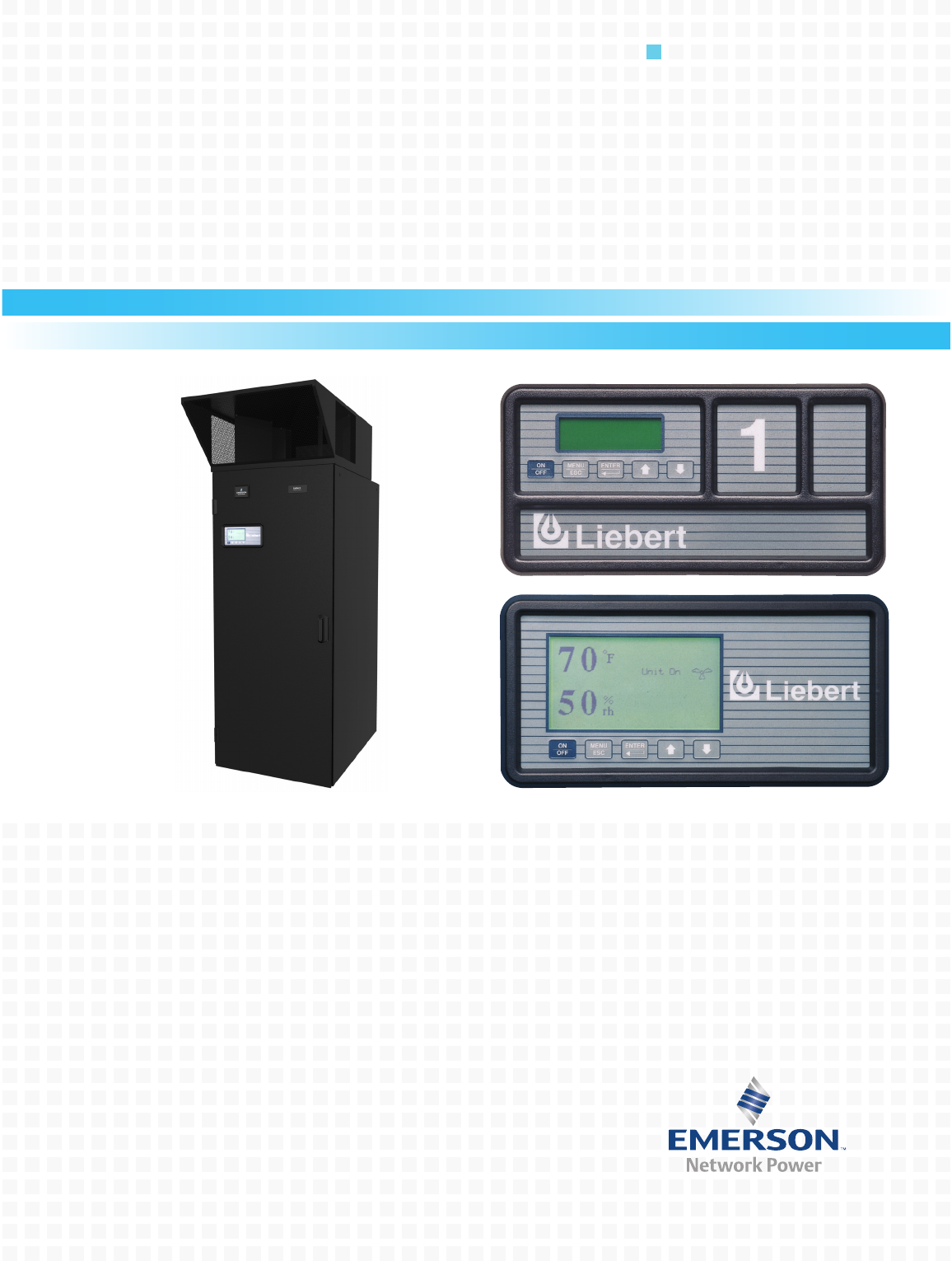
2.1 Liebert Challenger ITR
Liebert Challenger ITR provides the precision and flexibility required by a broad range of applica-
tions.
• Microprocessor-based controls (with a choice of monitoring systems based on your needs) allow
you to select temperature and humidity ranges.
• A-frame coil (oriented to airflow) provides a large cooling surface area, and more precise control of
temperature and humidity.
2.2 Multiple Configurations to Fit a Variety of Spaces
Though electronic equipment rooms share some common protection requirements, their application
requirements can vary greatly. The room may or may not have a raised floor or an existing heat rejec-
tion loop. Budget and space requirements may limit the options a contractor has.
2.3 Efficiency in Economic Terms
The Liebert Challenger ITR occupies 9.8 square feet (.91 square meters) of floor space. It can be
located either between equipment racks or at the end of a row of racks. With room floor space valued
at a premium per square foot, the small footprint of the Liebert Challenger ITR makes economic good
sense.
2.4 GLYCOOL
GLYCOOL is a patented Liebert process that can significantly reduce energy costs during periods of
low outdoor temperatures.
The GLYCOOL system is a normal glycol system with the addition of a second cooling coil, known as
an Econ-O-Coil, in the air handling unit and a three-way valve. During colder months, the glycol solu-
tion returning from the outdoor drycooler is routed to the Econ-O-Coil and becomes the primary
source of cooling for the room. At ambient temperatures below 35°F (1.6°C), the cooling capacity is
sufficient to handle the total cooling needs of the room. Because the compressor is responsible for the
majority of the power consumption of the air conditioning unit, a GLYCOOL system can substantially
reduce energy costs.
Precision Environmental Control for Industrial, Telecommunications, Medical and Data Processing Equipment
3
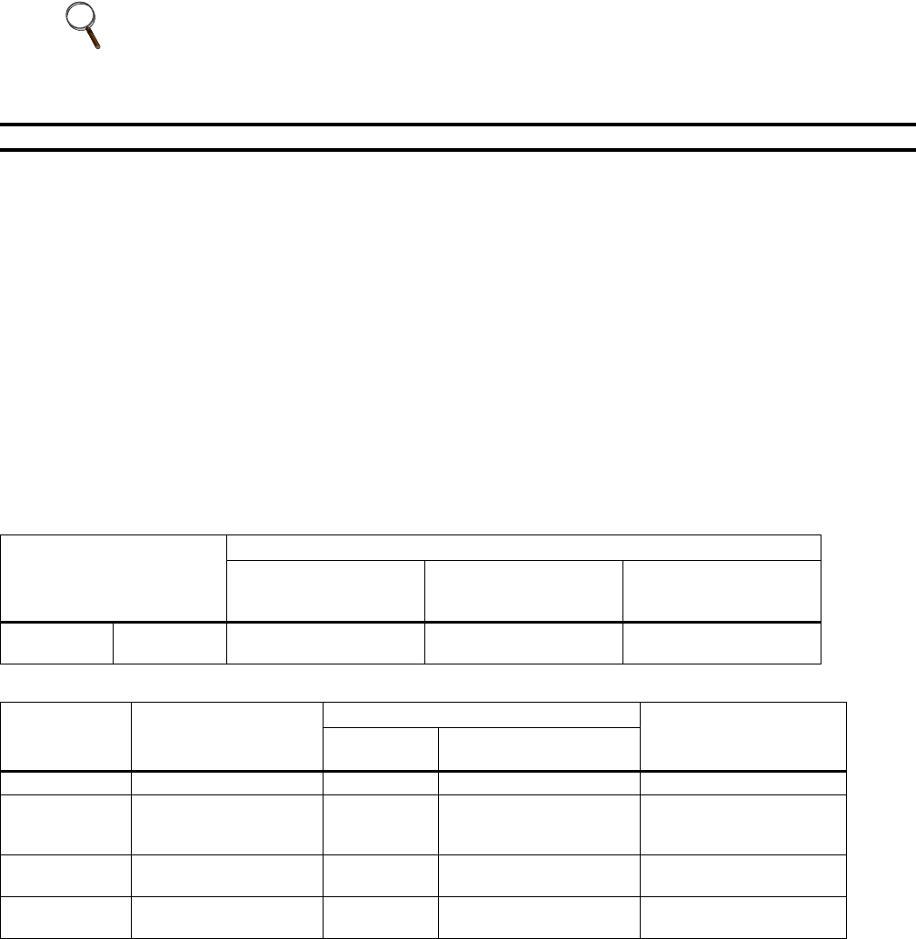
Figure 1 Unit configurations
Chilled Water, Self-Contained System Water-Cooled, Self-Contained System
Plenum
Available in two-way,
three-way and four-way
Free Discharge Grilles,
Solid Plenum for ducting
or low-profile, cold-aisle
discharge plenum
V-Frame
Coil
Condenser
Water Pipes
V-Frame
Coil
Scroll
Compressor Condenser
Remote Condenser
Water Source (not
supplied by Liebert)
IMAGES ARE
ILLUSTRATIVE ONLY
Air-Cooled, Self-Contained System
With Matching Condensers
Air-Cooled
Condenser
V-Frame Coil
Scroll Compressor
Glycol-Cooled, Self-Contained System
With Matching Drycooler and Pump
Scroll
Compressor
Condenser
V-Frame
Coil
Glycol Piping
Drycooler
Glycol
Pump
Expansion Tank
GLYCOOL-Cooled System
Scroll Compressor
Integrated
GLYCOOL Coil
Condenser Glycol
Pump
Drycooler
Expansion Tank
V-Frame
Coil
Glycol Piping
Precision Environmental Control for Industrial, Telecommunications, Medical and Data Processing Equipment
4
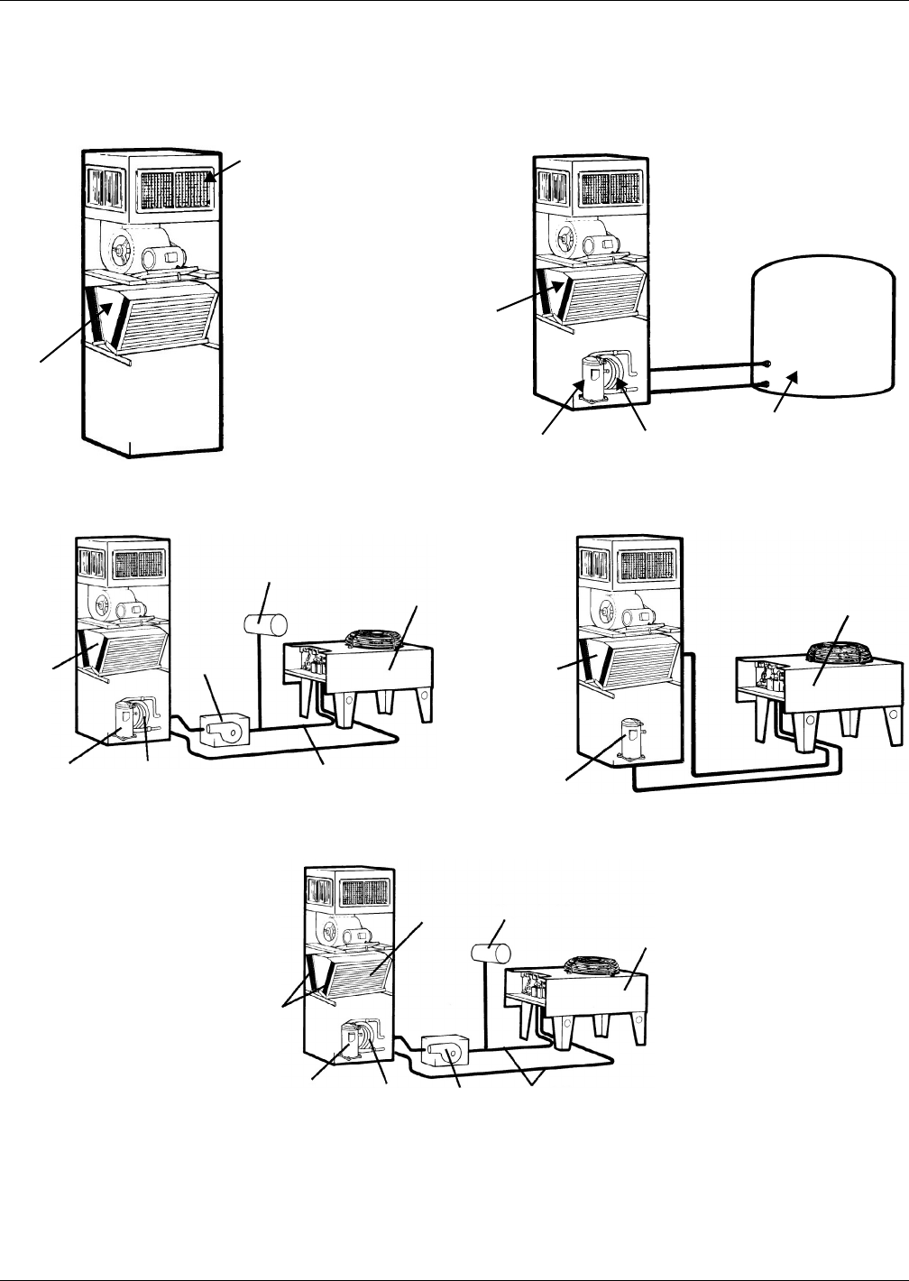
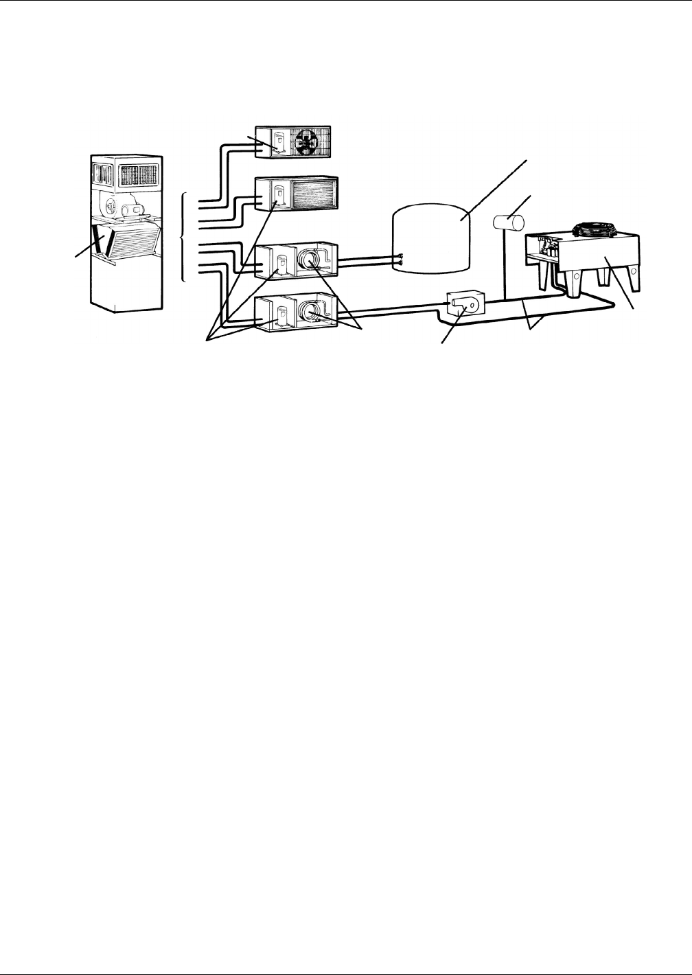
Figure 2 Unit configurations, continued
Split Systems Available
Scroll Compressor Glycol Pump
Glycol Piping
Drycooler
Expansion Tank
V-Frame
Coil
Scroll Compressor Remote Condenser
Water Source
(not supplied by Liebert)
Outdoor Prop-Fan
Air-Cooled Condensing Unit
Indoor Centrifugal Fan
Air-Cooled Condensing Unit
Indoor Water-Cooled
Condensing Unit
Coaxial
Condenser
Indoor Glycol-Cooled
Condensing Unit
IMAGE IS
ILLUSTRATIVE ONLY

Local Monitoring Systems
5
3.0 LOCAL MONITORING SYSTEMS
Two levels of microprocessor control systems are available providing precise control and monitoring of
the critical space.
The Advanced Microprocessor is standard, and the Advanced Microprocessor with Graphics
is optional. The main control functions are similar for both controls.
3.1 Control
The user must enter a three-digit password before making changes.
• Temperature Setpoint 65-85°F (18-29°C)*
• Temperature Sensitivity +1-10°F (0.6-5.6°C)
• Humidity Setpoint 20-80% RH*
• Humidity Sensitivity 1-30% RH
• High Temperature Alarm 35-90°F (2-32°C)
• Low Temperature Alarm 35-90°F (2-32°C)
• High Humidity Alarm 15-85% RH
• Low Humidity Alarm 15-85% RH
* The microprocessor may be set within these ranges; however, the unit may not be able to control to
extreme combinations of temperature and humidity.
3.2 Control Type
Factory set-up for Intelligent Control which uses “fuzzy logic” and “expert systems” methods. Propor-
tional and Tunable PID are user selectable options.
3.3 Internal System Control
•Compressor short cycle control: Prevents compressor short-cycling and needless compressor
wear.
•System auto restart: The auto restart feature will automatically restart the system after a
power failure. Time delay is programmable.
•Sequential Load Activation: On initial start-up or restart after power failure, each operational
load is sequenced to minimize total inrush current.
•Hot Water / Econ-O-Coil Flush Cycles: Hot water reheat coils and Econ-O-Coils are periodi-
cally flushed to prevent a build-up of contaminants.
•Temperature/Humidity Sensor Calibration: The sensors may be calibrated from the front
monitor panel to insure that all units in the room are similarly calibrated, assuring greater preci-
sion.
3.4 Monitoring
•Normal display: Includes present room temperature and humidity, active functions (cooling,
heating, dehumidifying), and any alarms.
•Operating status: Displays each control operation in percent.
•Read analog inputs function: Displays the present values of up to four analog inputs.
3.5 Diagnostics
•Input diagnostics: Reviews inputs to the control system.
•Control board diagnostics: Initiates a self-test of the control system.
•Output diagnostics: Tests major components by turning them on and off from the control panel.
Includes: main fan, compressor, liquid line solenoid valve, hot gas bypass valve, chilled water or
chilled GLYCOOL valve, R-5 relay, reheat, hot water reheat valve, humidifier, humidifier make-
up valve, and common alarm.
Local Monitoring Systems
6
3.6 Logging
•Alarm history log: The Advanced Microprocessor displays the 10 most recent alarms. The
Advanced Microprocessor with Graphics displays the most recent 60 alarms. Both provide a time
and date stamp for each event
•Run time log: Displays run time and hours for major components (also allows reset of run hours)
including compressors, GLYCOOL, fan, humidifier, and reheat.
3.7 Alarms
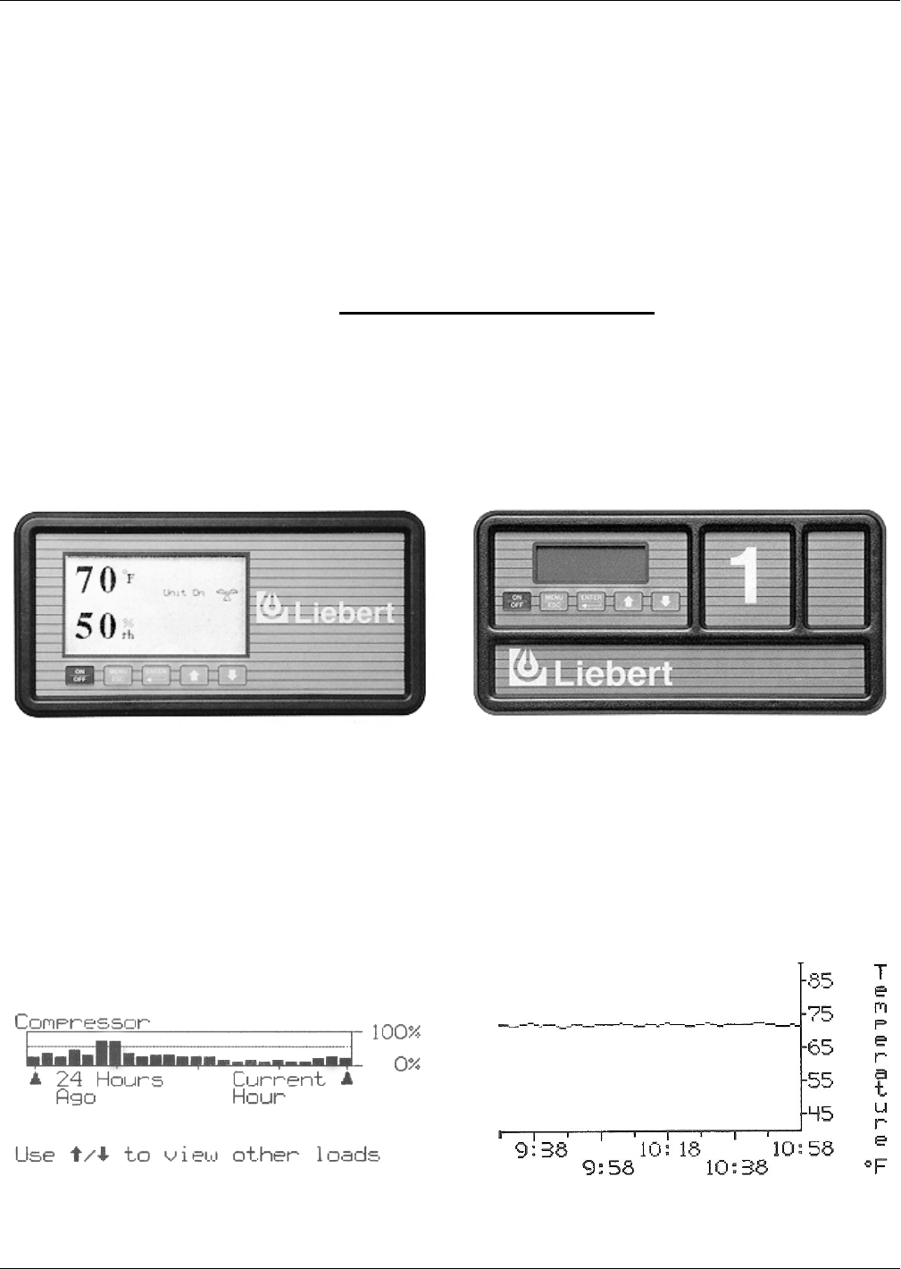
Figure 3 Microprocessor control systems
3.8 Graphical Displays—Advanced Graphic Control Only
• Individual plots of temperature, humidity and the four analog inputs.
• Bar graph plots of individual component run history by hour.
• Floor plan of optional water detection system layout including on alarm.
Status indication of operating modes with current temperature and humidity.
Figure 4 Optional Views With Advanced Graphics
• Humidifier Problem • Low Suction Pressure
• High Head Pressure • Short Cycle
• Change Filter • Loss Of Power
• Loss of Air Flow Custom Alarm (Maximum of Four)
• High Temperature • Water Under Floor
• Low Temperature • Smoke Detected
• High Humidity • Standby GC Pump On
• Low Humidity • Loss Of Water Flow
• Compressor Overload—Optional • Standby Unit On
• Main Fan Overload—Optional • User-Customized Text
Advanced Microprocessor w/Graphics Control
System—Optional. Backlit 240 x 128 dot matrix
graphics display.
Advanced Microprocessor Control System.
Backlit 4 x 20 Liquid Crystal Display.
The runtime screen provides data in either tabular
or easy-to-read graphic formats.
Histograms–historical depictions–of temperature or
humidity can be displayed on the screen for analysis.
This is especially helpful in tracking the environmental
factors of an alarm.

Standard Features—All Systems
7
4.0 STANDARD FEATURES—ALL SYSTEMS
4.1 Cabinet and Frame
The frame, 14 gauge, MIG welded tubular and formed steel, provides maximum support while 1"
(25.4mm) deep steel panels with 1-1/2 lb. (.68 kg) insulation protect and quiet the system. The front
door can be opened for service without shutting off the system. All components are accessible for ser-
vice/maintenance through the front and rear of the unit.
The Liebert Challenger ITR’s resistance to corrosion is enhanced by the black, powder-coat finish to
all frame components. Exterior panels are similarly protected with durable powder-coating.
4.2 Electrical Panel
The high voltage compartment contains the contactors, transformers and overloads and all other
high-voltage components.
Each high voltage component is protected by a separate overcurrent protective device. The entire high
voltage panel is enclosed by a safety lock dead front panel. When the front door is opened by operating
personnel, the high voltage components remain enclosed for operator safety.
4.3 Fan Section
The Liebert Challenger ITR features a quiet, low speed fan assembly with double inlet blower, life-
time lubrication and self-aligning ball bearings. The motor and variable pitch drive are mounted on
an adjustable base. The entire blower/ motor assembly is mounted on vibration isolators for smoother
operation.
The draw-through design of the fan section provides even air distribution across the coil, controlled
air for bypass humidification, elimination of air bypass around the filters and low internal cabinet
pressure drop.
4.4 Infrared Humidifier
High-intensity quartz lamps over the stainless steel humidifier pan permit clean, particle-free vapor
to be added to the air within 5 to 6 seconds of the electronic call from the microprocessor control.
The quartz lamps provide radiant energy that evaporates water in a pure state, without solids.
The Infrared Humidifier is equipped with an automatic water supply system that significantly
reduces cleaning maintenance. This system has an adjustable water over-feed to prevent mineral pre-
cipitation. A drain valve is provided to easily empty the humidifier pan prior to inspection or servic-
ing. A control valve regulates flow at water pressures between 5 and 150 psig (34.5 and 1034 kPa) and
includes a Y-strainer.
4.5 Electric Reheat
The two-stage 304 stainless steel reheat elements are a rigid, fin-tubular design that have extended
operation life. The reheat has ample capacity to maintain room dry-bulb conditions during a system
call for dehumidification. The two stages give an accurate, controlled response to the requirements of
the computer room. The low watt density, electrically enclosed elements are surrounded by the tube
and fins, reducing sheath temperatures and eliminating ionization.
4.6 Filters
The standard pleated 2" (51mm) filter with an efficiency of 20% (based on ASHRAE 52.1) can be
changed quickly and easily through the front of the unit.
Standard Features—All Systems
8
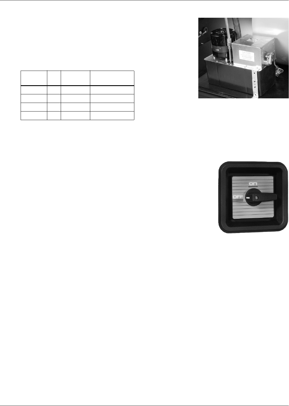
4.6.1 Condensate Pump
The condensate pump, mounted in the bottom of most units, is
used for unit drain water only. The condensate pump is complete
with sump, motor and pump assembly and automatic control.
The standard model has single float. A dual-float condensate
pump, which includes connections to unit, common alarm, unit
shutdown and one customer N/O contact is also available.
4.6.2 Remote Temperature/ Humidity Sensors
The remote temperature/ humidity sensors permit monitoring room conditions from an external
source. They are encased in an attractive case and are provided with a plug compatible shielded cable
in virtually any length.
4.6.3 Disconnect Switch—Locking Type
The locking disconnect switch, mounted in the electrical panel, is con-
nected to the safety lock dead front panel of the system and is inter-
locked mechanically. In this way the panel can’t be opened until the
switch is in the off position. And it complies with local codes as well as
those of the NEC.
Table 1 Condensate pump capacity
Voltage Hz
Capacity
GPH (l/s)
Head Pressure
ft. (kPa)
200/230 50 50 (189) 10 (30)
208/230 60 50 (189) 17 (51)
380/415 50 200 (757) 26 (78)
460 60 200 (757) 43 (128)
Disconnect Switch
(Locking)

Chilled Water System—Standard and Optional Features
9
5.0 CHILLED WATER SYSTEM—STANDARD AND OPTIONAL FEATURES
5.1 Chilled Water System—Standard Features
5.1.1 Cooling Coil
The chilled water cooling coil is designed for closed-loop applications using properly maintained
water. It is constructed of copper tubes and aluminum fins. To ensure quality, the V-frame coil is
manufactured to the highest standards in the industry.
5.1.2 Modulating Motor
The flow of chilled water through the cooling coil is controlled by an electronic modulating motor. The
microprocessor control will activate the motor when a need for cooling or dehumidification exists. The
motor will position the valve to precisely match the needs of the conditioned space.
5.1.3 Line Insulation
All chilled water piping within the Liebert Challenger ITR is fully insulated to assure full system
capacity and prevent condensation.
5.1.4 Three-Way Control Valve
The fully insulated control valve gives the conditioned space the precise cooling needed by electronic
equipment. Its unique design requires no overtravel linkages and never requires adjustment.
5.2 Chilled Water System—Optional Features
5.2.1 Chilled Water Flow Switch
The flow switch will activate the alarm system and/or shut down the system should the chilled water
supply be interrupted. The switch is factory wired and mounted in the chilled water valve compart-
ment.
5.2.2 High Pressure
For special applications, a high-pressure, modulating three-way or two-way valve can be provided.
The valve is designed for 400 psig (2758 kPa) water pressure.

Refrigeration Systems
10
6.0 REFRIGERATION SYSTEMS
Two versions are available:
• Self-Contained Systems
• Split Systems
6.1 Self-Contained Systems
These systems feature a scroll compressor and controls, expansion valve, hot gas bypass and evapora-
tor coil in the room unit.
Air-Cooled models also include a crankcase heater on the compressor and require field connection to
remote air-cooled condenser.
Water, Glycol and GLYCOOL models also include a coaxial condenser with field connections
required to the water or glycol coolant loop.
Water/Glycol models have two-way WRV with bypass.
GLYCOOL models have three-way WRV.
6.2 Split Systems
These systems feature the evaporator coil and expansion valve in the room unit, with the scroll com-
pressor, and the condensing equipment located in one of several different types of pre-charged con-
densing units.
6.3 Refrigeration System Components—Standard Features
6.3.1 Compressor
The heart of the refrigeration system is the compressor.
All self-contained evaporator units and split system condensing units contain a high efficiency, quiet
operating scroll compressor. The compressors have internal vibration isolating mountings, pressure
safety controls and built-in overload protection.
6.3.2 Evaporator Coil
The evaporator coil is designed for the high sensible heat ratio required by electronic equipment
applications. The copper tube, aluminum fin coils are configured in a V-frame for smooth air flow
through the unit.
6.3.3 Safety Control
Every Liebert Challenger compressor has a high-pressure switch with an exclusive manual reset after
high pressure cut-out. This prevents cycling the compressor at high pressure, resulting in greater effi-
ciency and longer compressor life.
6.3.4 Expansion Valve
The externally equalized thermostatic expansion valve smoothly controls the flow of refrigerant
through the coil and provides precise control of superheat.
Air-Cooled System—Standard and Optional Features
11
7.0 AIR-COOLED SYSTEM—STANDARD AND OPTIONAL FEATURES
7.1 Air-Cooled, Self-Contained Systems—Standard Features
7.1.1 Pump Down Control
The compressor pump-down control is accomplished by a liquid-line solenoid valve used in conjunc-
tion with a low pressure switch.
7.1.2 Condenser
The Liebert manufactured low profile, direct drive propeller fan type air-cooled condenser provides
quiet, efficient operation.
It is constructed of aluminum with a copper tube and aluminum fin coil for corrosion resistance. An
integral, factory wired and tested control panel reduces installation time.
7.1.3 Fan Speed Control
The winter control system features a variable speed motor and a specially designed solid-state fan
speed control transducer.
The transducer senses refrigerant pressure and varies the speed of the fan motor to maintain con-
stant condensing temperature and system capacity. This system permits operation at ambient tem-
peratures as low as -20°F (-29°C).
7.2 Air-Cooled, Self-Contained Systems—Optional Features
7.2.1 Liebert Lee-Temp Winter Control Condenser
The Liebert Lee-Temp winter control system’s heated receivers permit startup and positive head
pressure control at ambient temperatures as low as -30°F (-34.4°C). The Liebert Lee-Temp package
includes insulated receiver, a pressure relief valve, three-way head pressure control valves, and rota-
lock valves (see Figure 5 below).
7.2.2 Quiet-Line Condensers
Quiet-Line Condensers can help your facility meet the strictest noise codes, and do so at less cost than
traditional condensers with acoustical shielding.
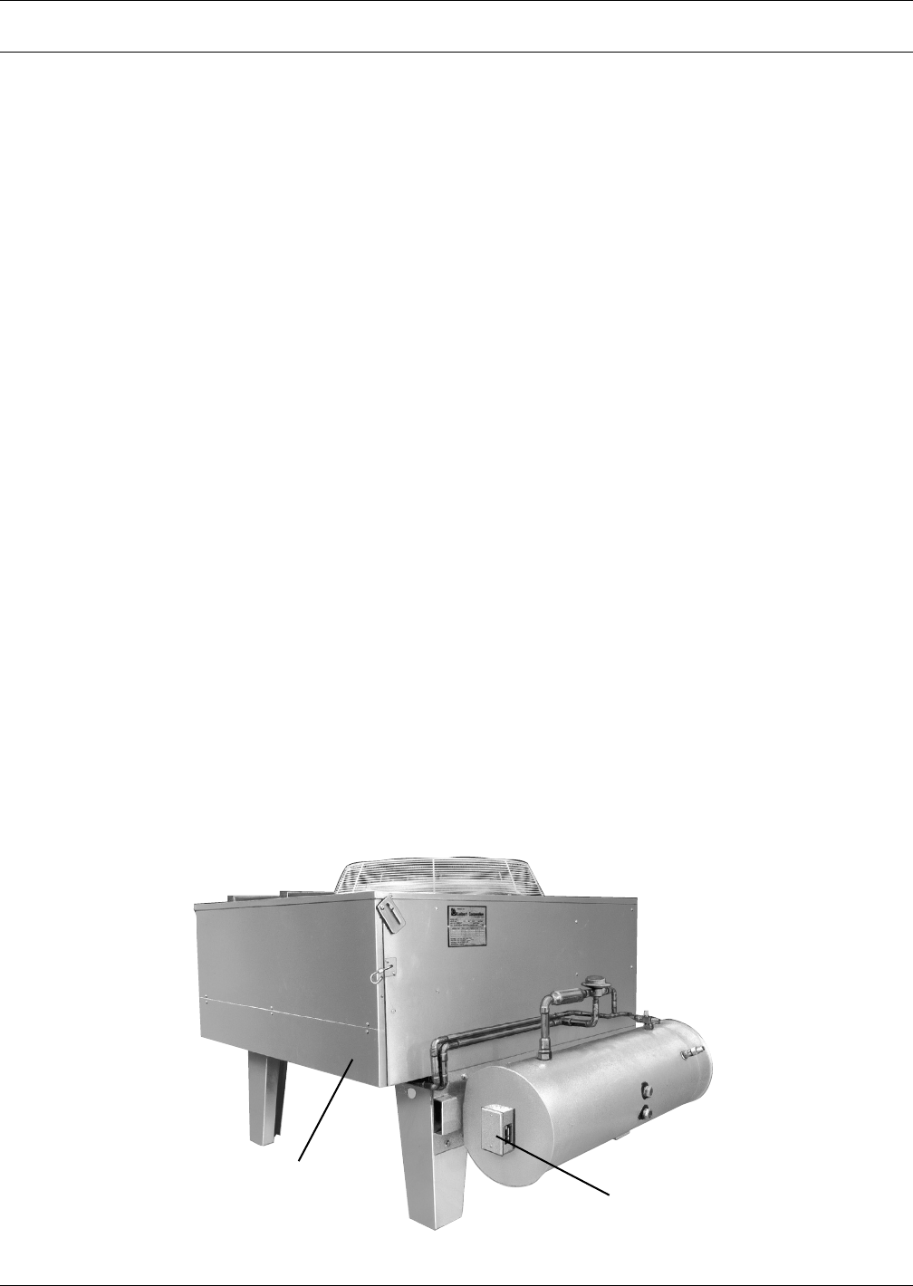
Figure 5 Air-cooled condenser with Liebert Lee-Temp
Air-Cooled Condenser
Liebert Lee-Temp
Package (optional)
Air-Cooled System—Standard and Optional Features
12
7.3 Air-Cooled Split Systems—Standard Features
7.3.1 Centrifugal Fan, Condensing Unit
The centrifugal condensing unit’s copper-tube, aluminum-fin coil is equipped with low-temperature
controls to ensure year-round operation to -20°F (-29°C). The condensing unit is factory-wired,
charged and tested and is ready for final connections.
The centrifugal fan condensing unit includes scroll compressor, condenser coil, centrifugal blower
assembly, high-pressure switch and Liebert Lee-Temp head pressure control.
Condensing unit has hot gas bypass standard feature which bypasses hot gas around the compressor
directly to the suction side of the compressor to provide capacity control and reduce compressor
cycling. System includes liquid injection valve to maintain proper suction superheat.
Unit must be mounted indoors. Duct flanges are provided.
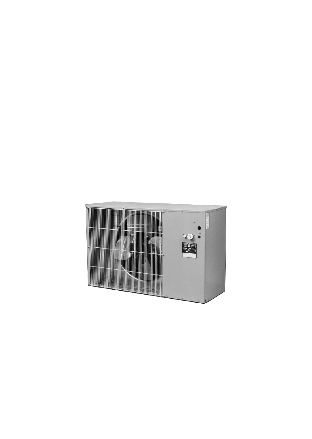
7.3.2 Propeller Fan Condensing Unit
The air-cooled condensing unit can be mounted on the roof or a ground level site. The condensing unit
housing is manufactured of galvanized steel with a powder coat finish. The copper-tube, aluminum-
fin coil is equipped with low temperature controls to assure year-round operation to -30°F (-34.4°C).
The condensing unit is completely factory-wired, charged and tested and is ready for final connec-
tions. (See illustration below)
The standard prop fan condensing unit includes scroll compressor, prop fan, high head pressure
switch, hot gas bypass and Liebert Lee-Temp head pressure control (for operation down to -30°F (-
39°C) ambient.)
Figure 6 Outdoor propeller fan condensing unit
7.3.3 Propeller Fan Condensing Unit Options
This unit is available in these optional configurations:
• 105°F (40°C) ambient for high ambient conditions.
• 95°F (35°C) ambient Quiet-Line for low noise level conditions below 58 dBa.
7.4 Air-Cooled Split Systems—Optional Features
Factory-installed, non-fused disconnect switch allows turning off the Challenger ITR for main-
tenance. Disconnect switch is available on indoor condensing units only.

Water/Glycol-Cooled Systems—Standard and Optional Features
13
8.0 WATER/GLYCOL-COOLED SYSTEMS—STANDARD AND OPTIONAL FEATURES
8.1 Water/Glycol Self-Contained Systems—Standard Features
Liquid-Cooled Condensers
A co-axial condenser provides ample capacity to handle the heat rejection needs of the system while
using a minimum of liquid and low total pressure drop.
Regulating Valves
Head pressure operated regulating valves accurately control the condensing temperature and main-
tain system capacity for various entering liquid flow rates and temperatures. Two-way valves with
bypass are standard.
8.2 Water/Glycol-Cooled, Self-Contained System—Optional Features
Three-way Regulating Valves
Three-way valves provide accurate control of condensing temperature and thus maintain constant
system capacity while also keeping the condenser water flow rate constant.
High Pressure
The high pressure option for the condenser circuit consists of a regulating valve and a condenser
rated at 350 psig (2413 kPa) water-pressure. This option is required in applications with large static
head pressures.
Compressor Crankcase Heater
A compressor crankcase heater is available to prevent the migration of refrigerant to the compressor
during off cycles.
Hot Gas Reheat
The hot gas reheat assembly consists of a three-way directional solenoid operated valve and a hot gas
reclaim coil.
70/30 Cu-Ni Econ-O-Coil
This coil replaces the standard copper tube coil to provide improved resistance to corrosion. This
option must be specified whenever a GLYCOOL or Dual Cooling Source system is applied to a cooling
tower loop or other open water system.
8.3 Water/Glycol Split System—Standard Features
Water/Glycol-Cooled Condensing Units
Factory charged and sealed, the water-cooled condensing unit is ready to be installed quickly and eas-
ily. The counter-flow coaxial condenser with two-way or three-way regulating valve designed for 150
psi (1034.3 kPa) is matched to the heat rejection requirements of the compressor for a variety of flow
rates and fluid temperatures.
Condensing unit has a hot gas bypass standard feature that bypasses hot gas around the compressor
directly to the suction side of the compressor to provide capacity control and reduce compressor
cycling. System includes liquid injection valve to maintain proper suction superheat.

Water/Glycol-Cooled Systems—Standard and Optional Features
14
8.4 Water/Glycol-Cooled, Split System—Optional Features
High Pressure
The high pressure option for the condenser circuit consists of a two-way or three-way water regulat-
ing valve and condenser rated at 350 psig (2413 kPa) water pressure. This option is required in appli-
cations with large static heads.
Factory Installed Non-Fused Disconnect Switch
Allows unit to be turned off for maintenance. Disconnect switch is available on indoor condensing
units only.
70/30 Cu-Ni Econ-O-Coil
This coil replaces the standard copper tube coil to provide improved resistance to corrosion. This
option must be specified whenever a GLYCOOL or Dual Cooling Source system is applied to a cooling
tower loop or other open water system.
8.4.1 Glycol-Cooled System—Heat Rejection Devices
8.4.2 Self-Contained and Split Systems
Fan Speed Control Drycooler
The Liebert manufactured Fan Speed Control drycooler is constructed of aluminum and features cop-
per tubes and aluminum fin design. It is low profile, propeller fan type and provides quiet, trouble
free heat rejection. The drycooler features a variable speed fan motor and a specially engineered solid
state fan speed transducer. The transducer senses the temperature of the leaving glycol and modu-
lates the speed of the fan to maintain proper glycol temperatures. An integral, factory-wired and
tested control panel reduces installation time.
Glycol Pump
The glycol system includes a matching centrifugal glycol pump. It is mounted in a vented, weather-
proof enclosure. Optional Equipment—See page 16.

GLYCOOL Systems—Standard and Optional Features
15
9.0 GLYCOOL SYSTEMS—STANDARD AND OPTIONAL FEATURES
9.1 GLYCOOL—Self-Contained Models Only
The Liebert GLYCOOL free-cooling system is integrated with a glycol-cooled Liebert Challenger ITR.
At outdoor temperatures below 35°F (1.6°C), the Econ-O-Coil is capable of providing total system
capacity. At outdoor temperatures between 35° and 65°F (1.6° and 18.3°C), the unique modulating
valve permits partial cooling of the space by the Econ-O-Coil with the DX system picking up the rest
of the load. Above 65°F (18.3°C) the unit functions as a glycol unit and all the cooling is accomplished
by the DX system. When cooling is required, the three-way modulating valve and water regulating
valve direct glycol (from the heat rejection loop) to the Econ-O-Coil located upstream of the evaporator
coil, to the condenser, or to both.
The GLYCOOL system contains all the standard features of a glycol-cooled system plus the following.
9.2 GLYCOOL System—Standard Features
9.2.1 Comparative Temperature Monitor
A solid-state temperature monitor compares the room air temperature and entering glycol tempera-
ture. When air temperature is higher than glycol temperature, the monitor communicates to the
microprocessor control that “free-cooling” is available.
9.2.2 Econ-O-Coil
The Econ-O-Coil is strategically located in the return air stream of the environmental control system.
This coil is designed for closed-loop applications using properly treated glycol solutions. Applications
using a cooling tower loop or other open water system must specify a 70/30 Cu-Ni Econ-O-Coil for
improved corrosion resistance.
The air is first filtered before entering the coil and then is either precooled or totally cooled before
entering the refrigeration coil. The glycol flow to the coil is controlled by a pre-piped modulating
three-way valve. When supplied with a 45°F (7.2°C) glycol solution, the coil is sufficiently sized to
offer the identical cooling capacity as is obtained during the refrigeration cycle of the compressor.
9.2.3 GLYCOOL Three-Way Control Valve
The GLYCOOL Three-Way Control Valve opens full anytime the temperature of the glycol solution is
below room temperature, to take full advantage of all possible free cooling. As the outdoor ambient
drops, the three-way control valve modulates the flow to the Econ-O-Coil. It maintains constant tem-
perature in the room and includes operating linkage and electronic motor. Unlike other valves of this
nature, there is no over travel linkage or end switches to be adjusted.
9.2.4 Glycol-Regulating Valve
A head pressure operated glycol regulating valve accurately controls the condensing temperature and
system capacity for various entering glycol temperatures. The valve has three-way action.
GLYCOOL Systems—Standard and Optional Features
16
9.2.5 Drycooler
The Liebert manufactured drycooler is constructed of aluminum with a copper tube aluminum fin
coil. The low profile design features multiple direct drive propeller type fans, balanced to the heat
rejection load. An integral, factory wired and tested control panel reduces installation time.
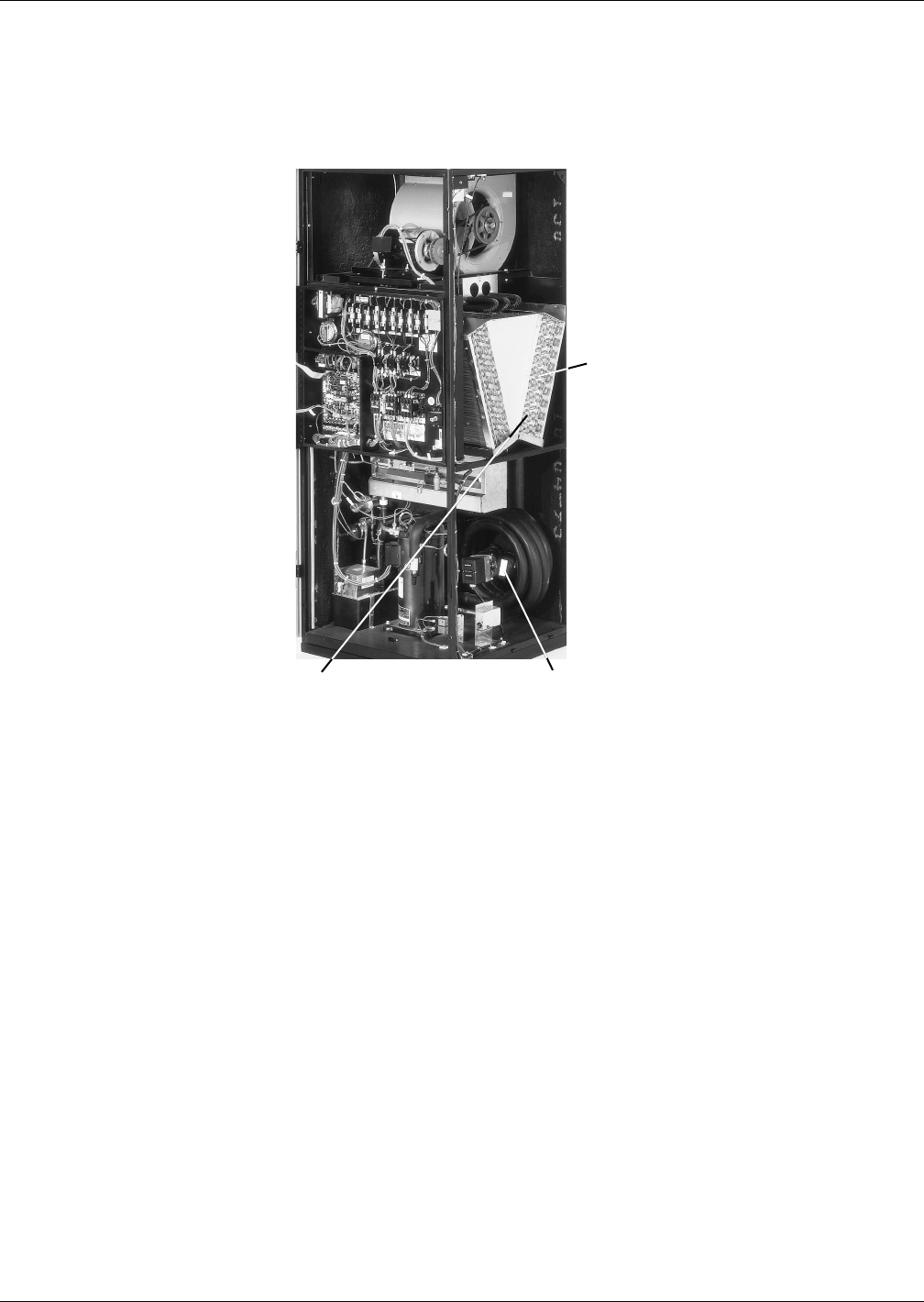
Figure 7 Liebert Challenger ITR unit core
9.3 Glycol and GLYCOOL-Cooled—Optional Equipment
High Pressure
For high pressure applications, the GLYCOOL system can be equipped with components rated at 300
psig (2069 kPa).
9.3.1 Dual Pump Package
The dual pump package features two full size glycol pumps, each capable of providing sufficient flow
for system operation. A flow switch will sense the loss of flow, should the lead pump fail, and automat-
ically command the standby pump to start. The complete system includes dual pump housing, pumps,
lead-lag switch and flow switch (for field installation). The dual pump package provides redundancy,
protecting against costly downtime in the computer room.
Quiet-Line Drycoolers
Quiet-Line Drycoolers can help your facility meet the strictest noise codes, and do so at less cost than
traditional drycoolers with acoustical shielding.
Evaporator
Coil
Three-way GLYCOOL
Control Valve
Econ-O-Coil
Optional Equipment—All Systems
17
10.0 OPTIONAL EQUIPMENT—ALL SYSTEMS
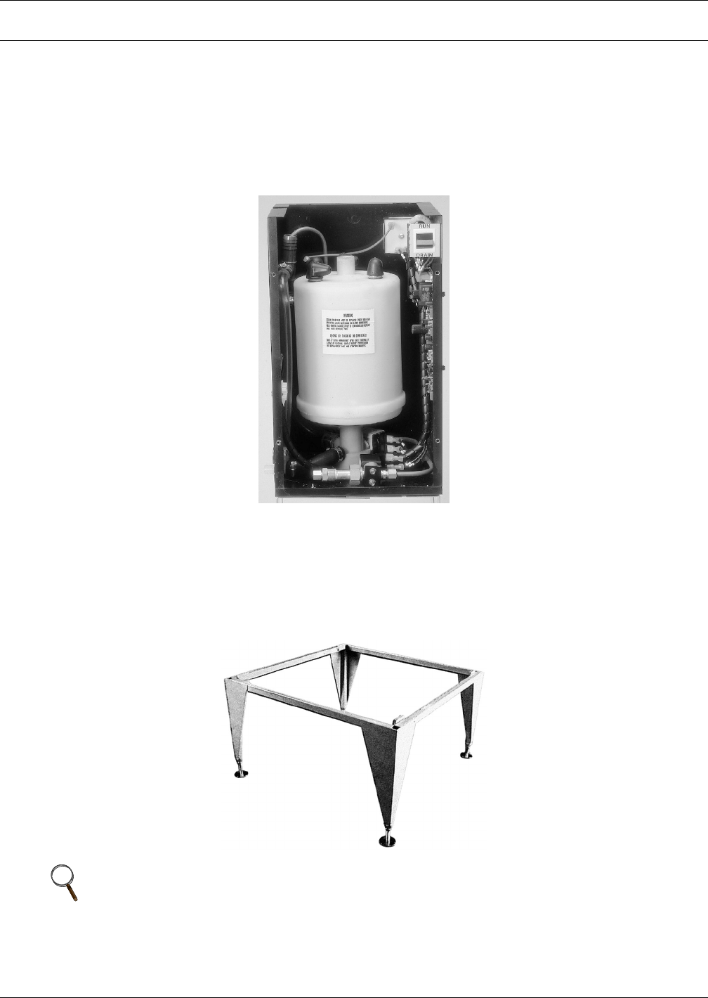
10.1 Steam Generating Humidifier
Clean, pure steam is generated in a disposable canister that is complete with supply and drain valves,
electronic controls and steam distributor. The humidifier is provided with an automatic flush cycle to
lengthen service life. An indicator on the Liebert Challenger ITR monitor panel is activated when the
canister should be changed.
Figure 8 Steam generating humidifier
10.2 Adjustable Floor Stand
Available in heights from 9" to 24" (228.6 to 609.6mm) in 3" (76.2mm) increments, adjustable +1-1/2"
(38.1mm). Allows for installation and connection of the Liebert Challenger ITR prior to installation of
the raised floor.
Figure 9 Adjustable floor stand
NOTE
Some options or combinations of options may result in reduced air flow. Consult factory for
recommendations.
Optional Equipment—All Systems
18
10.3 SCR Reheat
This reheat uses stainless steel elements and also includes the necessary sensors and controls to pro-
vide variable heat output to help maintain tighter control of room conditions, especially in lightly
loaded applications. (Contact factory for available voltages.) Direct expansion units only.
10.4 High-Efficiency Filter
Four optional filters are available in lieu of standard package. A 4" (102mm) 20%, 30%, 40%-45% or
60%-65% filter may be specified. (Efficiency based on ASHRAE 52.1). 2" (51mm) 20% pre-filters may
also be specified.
10.5 High External Static Blowers
These blower/motor packages are available where external static pressures are up to 2.0 inches (500
Pa) on 60 Hz units, and up to 1.5 inches (370 Pa) on 50 Hz units. These blowers are rigidly mounted
for ducting directly to the blower housing.
(Consult the factory for specific applications.)
10.6 High-Efficiency Motors
These motors replace the standard efficiency motors to provide increased energy savings during oper-
ation (consult factory for specific efficiencies).
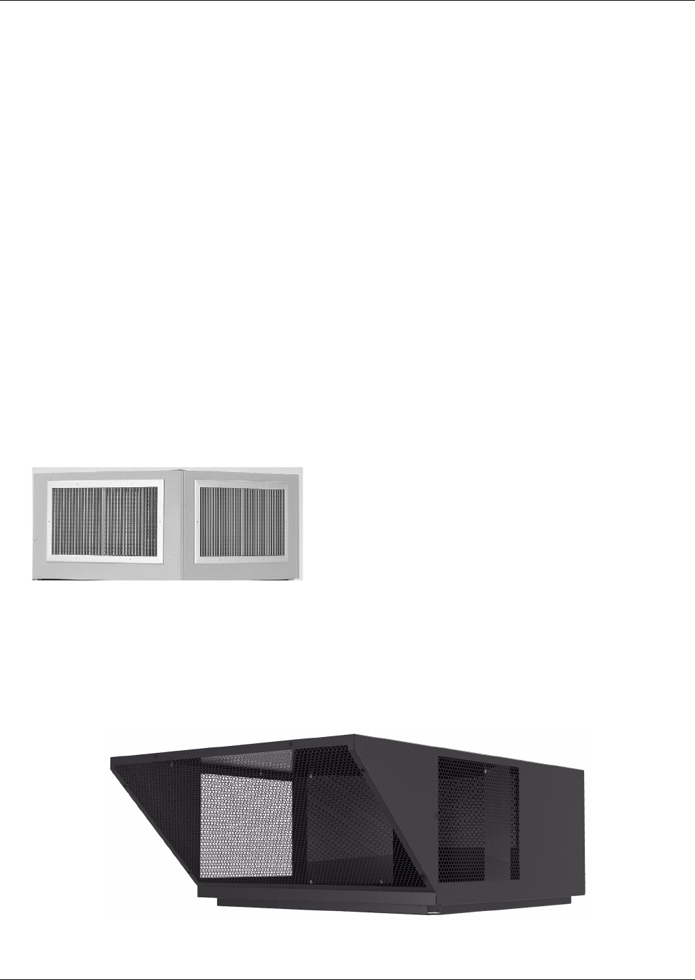
10.7 Plenums
Standard height of 18" (457mm) with top duct connection or two-way, three-way or 4-way grille dis-
charge styles available.
10.8 Low-Profile Plenum with Cold-Aisle Discharge
This plenum is designed to distribute supply air to electronic equipment beside and across from the
cooling unit. In addition to air exiting the front of the plenum, internal baffles direct air through the
left-side and right-side discharge vents. Factory-supplied hardware allows air to be blocked from exit-
ing one side of the plenum, allowing the cooling unit to be installed at the end of a row of equipment.
Plenum With Two-Way Grille
Low-Profile, Cold Aisle Discharge Plenum
Optional Equipment—All Systems
19
10.9 Smoke Detector
The smoke detector senses the return air, shuts down the unit upon detection, and sends visual and
audible alarm. Dry contacts are available for a remote customer alarm. This smoke detector is not
intended to function as or replace any room smoke detection system that may be required by local or
national codes.
Supervised smoke detectors are also available as an option. Consult factory.
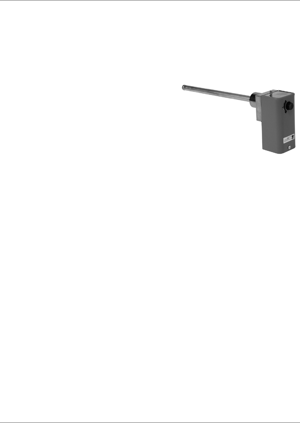
10.10 Firestat
The firestat senses return air temperature of the sys-
tem. Upon sensing high temperatures, the environmen-
tal control system is shut down. Required by codes in
certain areas.
10.11 Hot Water Reheat
Controlled by a two-way solenoid valve from the micro-
processor control panel, these economical reheats have
the capacity to maintain dry bulb conditions when the
system is calling for dehumidification. The system is
completely pre-piped and includes a control valve and
Y-strainer. The reheat coil is constructed of copper
tubes and aluminum fins.
Firestat

Comprehensive Monitoring Systems—Optional
20
11.0 COMPREHENSIVE MONITORING SYSTEMS—OPTIONAL
You will find a full range of monitoring and control systems, communications modules designed to
interface Liebert equipment with a variety of building management systems, plus stand-alone moni-
toring, control and leak detection devices.
11.1 Enterprise Monitoring Systems
SiteScan Web is a comprehensive critical systems monitoring solution dedicated to ensuring reliabil-
ity through graphics, event management and data extrapolation. The standard Web interface allows
users easy access from anywhere at anytime.
• Single- and multi-site applications.
• Event management and unit control.
• Trend and historical data captures and reporting.
• Full ASHRAE BACnet compatibility.
• Java based.
• Windows 2000 and XP compatible.
Liebert SiteLink®
• Connectivity to building management systems using Modbus and BACnet.
Liebert Site I/O™
• Integrates sensors and contacts.
Liebert Site TPI™
• Integrates non-Liebert equipment.
11.2 Network Monitoring Systems
The Liebert IntelliSlot® line of products leverages one-to-one unit connections and your existing net-
work for a comprehensive monitoring solution for distributed equipment.
Liebert IntelliSlot Web/485 Card With Adapter
• Monitoring option available for Liebert precision air conditioning units.
• Web interface for viewing and control.
• Modbus interface for building management systems.
• SNMP interface for network management systems.
Liebert Nform™
• Centralized monitoring of all Liebert SNMP enabled devices.
• Event and alarm management.
• Adaptable and configurable graphical user interface.
• Integration of third-party SNMP enabled devices through custom Liebert services.
• Windows NT, 2000 and XP compatible.
11.3 Stand-Alone Monitoring and Leak Detection Solutions
Autonomous microprocessor controlled modules are available to provide supervision, control and
remote notification of Liebert equipment. These stand-alone devices include:
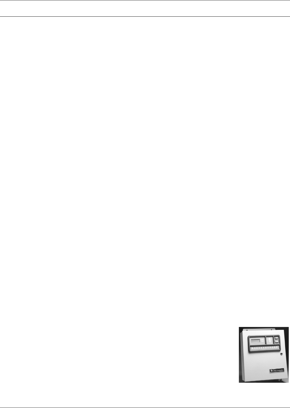
Contact Closure Alarm Panels
• Continuously monitor critical support equipment and instantly notify on alarm condition.
Autochangeover Control Panels
• Sequence the operation of multiple environmental units.
Comprehensive Monitoring Systems—Optional
21
Leak Detection Modules
• Provide quick detection and location of hazardous fluid leaks.
Discrete Output Interface Card
• Straightforward way to tie environmental units to a building management system or alarm panel.
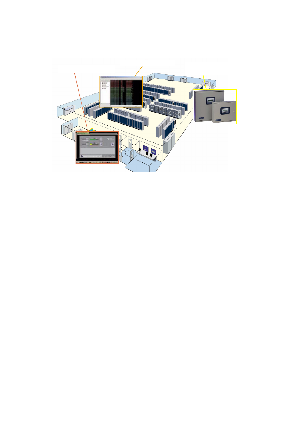
Figure 10 Monitoring configurations
Enterprise Monitoring
Network Monitoring Stand-Alone Monitoring
and Leak Detection
Comprehensive Monitoring Solutions—Optional
22
12.0 COMPREHENSIVE MONITORING SOLUTIONS—OPTIONAL
12.1 Liebert SiteScan® Web
Liebert SiteScan Web is a monitoring solution for critical environments that utilize a facility-view
approach. The system enables communications from Liebert environmental and power units—as well
as many other pieces of analog or digital equipment to a front end software package that provides
monitoring, control and alarm management.
Liebert SiteScan monitoring gives you decision making power to effectively manage the equipment
that is critical to your business. Designed with flexibility for large, complex systems as well as
smaller, single-site facilities, the Liebert SiteScan line of products can provide real-time status and
alarms.
12.2 Liebert SiteLink
The microprocessor-based module provides two-way communication between an existing building
management system and up to 12 Liebert units via Modbus or BACnet.
12.3 Liebert Nform
Liebert Nform centralizes the management of your distributed Liebert network equipment. Liebert
Nform software solution combines full-scale monitoring with the use of the existing network infra-
structure—so the cost of dedicated, out-of-band communications cabling is eliminated. It is both scal-
able and adaptable so it can grow as your systems expand and needs change. Liebert Nform will
monitor any Liebert SNMP device that supports a network interface, such as the Liebert IntelliSlot
485 Card With Adapter and the Liebert IntelliSlot Web/485 Card With Adapter. Authenticated alarm
management and event notification ensures that alarms are detected and acted upon, which allows
problems to be quickly resolved.
12.4 Liebert IntelliSlot Web/485 Card With Adapter and Liebert IntelliSlot 485 Card With
Adapter
The Liebert IntelliSlot Web/485 Card With Adapter and the Liebert IntelliSlot 485 Card With
Adapter provide Ethernet connectivity for Liebert equipment. Operating status and alarms are com-
municated via the network to external systems utilizing industry standard open protocols.
12.5 Environmental Discrete Outputs Card
The Environmental Discrete Outputs Card (ENV-DO) provides 16 discrete outputs, corresponding to
status and major alarm conditions. These Form-C contact closures provide a straightforward means
to connect Liebert environmental units to Building Management Systems (BMS), I/O or alarm panels.
12.6 Remote Contact Monitor (RCM4)
LEDs display customized alarm indication for any dry contact input including alarms for Liebert
environmental, power and UPS systems. The RCM4 monitors and displays four dry contact points.
12.7 Auto-Changeover Control
Up to eight environmental units can be automatically and centrally controlled for
emergency switching and to balance unit runtime. The AC3 controls two or three
units. The RAC2-8 controls two through eight units and has the ability to provide
alarm notification to pagers.
Auto-Changeover -
RAC2-8
Comprehensive Monitoring Solutions—Optional
23
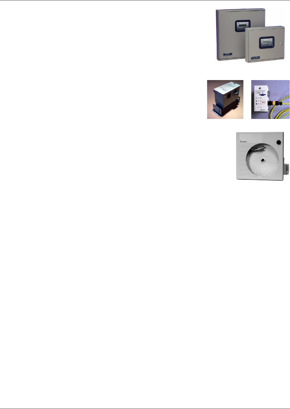
12.8 Universal Monitor
The Universal Monitor keeps personnel on-site and at remote locations
apprised of the status of equipment through local alarming and remote
paging services. The panel will interface with anything that closes an
electrical contact and any device with a 4-20mA signal. To improve pro-
cess efficiency and troubleshooting, the panel tracks data in an alarm
log, an event log and a trend log. The Universal Monitor has a local
LCD interface and a remote dial-up interface.
12.8.1 Leak Detection
Zone detectors with cable or single point detectors provide fast and
accurate indication of water in you critical space. These systems com-
municate with your unit or with a separate monitoring system. Area
water detection cable with distance measurement and monitoring
protects your entire room. This system quickly and accurately calcu-
lates and displays the location of water on the cable, allowing you to
promptly fin and correct a leak.
12.8.2 Temperature and Humidity Recorder
A seven-day temperature and humidity recorder permits close examination of
computer room environment condition and can be used as a permanent record of
the environmental control system’s operation efficiency. The system includes
pens, 100 recording charts; two bottles of recording ink (1 red ink and 1 blue
ink).
Universal Monitor
Large and Small Enclosures
Area Leak
Detection
Zone Leak
Detection
System Data
24
13.0 SYSTEM DATA
Table 2 Liebert Challenger ITR air-cooled data—60 Hz
System Type
BR = Horizontal Flow Self-Contained
Split Systems
w/Outdoor Prop-Fan
Condensing Unit
w/Indoor Centrifugal
Condensing Unit
Indoor Unit BR 067A BR 060E BR 060E
Net Capacity Data BTU/H kW BTU/H kW BTU/H kW
100°F DB, 70°F WB (37.8°C DB, 21.1°C WB) 20% RH
Total 78,100 22.9 76,200 22.3 73,200 21.4
Sensible 78,100 22.9 76,200 22.3 73,200 21.4
Non Standard Flow Rates 2400 CFM 2300 CFM 2100 CFM
95°F DB, 68.3°F WB (35°C DB, 20.2°C WB) 24% RH
Total 77,500 22.7 75,800 22.2 73,000 21.4
Sensible 77,500 22.7 75,800 22.2 73,000 21.4
Non Standard Flow Rates 2700 CFM 2500 CFM
90°F DB, 66.5°F WB (32°C DB, 19.2°C WB) 28% RH
Total 73,600 21.6 72,400 21.2 70,600 20.7
Sensible 73,600 21.6 72,400 21.2 70,600 20.7
85°F DB, 64.4°F WB (29.4°C DB, 18°C WB) 32% RH
Total 69,700 20.4 68,400 20.0 66,800 19.6
Sensible 69,700 20.4 68,400 20.0 66,800 19.6
80°F DB, 62.7°F WB (26.7°C DB, 17.1°C WB) 38% RH
Total 66,000 19.3 64,400 18.9 63,100 18.5
Sensible 66,000 19.3 64,400 18.9 63,100 18.5
80°F DB, 66.5°F WB (26.7°C DB, 19.2°C WB) 50% RH
Total 66,900 19.6 65,300 19.1 63,800 18.7
Sensible 54,600 16.0 54,000 15.8 53,400 15.6
75°F DB, 62.5°F WB (23.9°C DB, 16.9°C WB) 50% RH
Total 62,700 18.4 60,800 17.8 59,600 17.5
Sensible 53,000 15.5 52,300 15.3 51,800 15.2
75°F DB, 61.1°F WB (23.9°C DB, 16.2°C WB) 45% RH
Total 61,200 17.9 60,700 17.8 59,600 17.5
Sensible 57,000 16.7 60,700 17.8 59,600 17.5
72°F DB, 60.1°F WB (22.2°C DB, 15.6°C WB) 50% RH
Total 60,200 17.6 58,200 17.1 57,200 16.8
Sensible 52,000 15.2 51,200 15.0 50,700 14.9
72°F DB, 58.7°F WB (22.2°C DB, 14.8°C WB) 45% RH
Total 58,900 17.3 58,400 17.1 57,500 16.8
Sensible 55,800 16.3 58,400 17.1 57,500 16.8
Fan Data (Blower A12x9AT)**
Standard Air, CFM (CMH) 2800 (4760) 2800 (4760) 2800 (4760)
Standard Fan Motor, hp (kW) 1-1/2 (1.1) 1-1/2 (1.1) 1-1/2 (1.1)
Opt Fan Motor, hp (kW) 2 (1.5) 2 (1.5) 2 (1.5)
Ext Static, in. WG (Pa) .3 (75) .3 (75) .3 (75)
Evaporator Coil (V-FRAME, at standard conditions)
Face Area, ft.2 (m2) 6.67 (.62) 6.67 (.62) 6.67 (.62)
Rows 4 4 4
Face Velocity - FPM (m/s) 405 (2.1) 405 (2.1) 405 (2.1)
Electric Reheat 2 Stage (Stainless Steel, Fin Tubular) - Standard
Capacity, inc. motor heat, BTU/H (element kW) 56,200 (15) 56,200 (15) 56,200 (15)
Hot Water Reheat 180°F (82.2°C) EWT, 75°F (23.9°C) EAT - Optional (includes std air volume and opt fan motor hp)
Capacity, inc. motor heat, BTU/H (kW) 88,700 (26.0) 88,700 (26.0) 88,700 (26.0)
Flow Rate - GPM (l/s) 5.0 (.32) 5.0 (.32) 5.0 (.32)
Pressure drop - ft. (kPa) 16.9 (50.4) 16.9 (50.4) 16.9 (50.4)
* The net capacity data has fan motor heat factored in for all ratings and the entering air condition of 72°F (22.2°C) and 50% RH is the
standard rating for ASHRAE 127-2001. All capacities are nominal values; actual performance will be ±5%.
** Data rated with 2" 20% ASHRAE filter. Some options or combinations of options may result in reduced airflow. Consult factory for
recommendations.
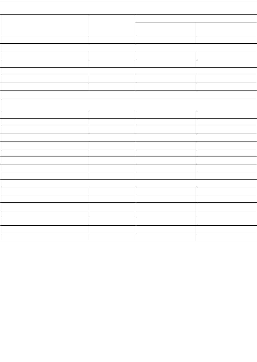
System Data
25
Table 3 Liebert Challenger ITR air-cooled data—60 Hz (continued)
System Type
Self-Contained
Split Systems
w/Outdoor Prop-Fan
Condensing Unit
w/Indoor Centrifugal
Condensing Unit
Indoor Unit BR 067A BR 060E BR 060E
Infrared Humidifier - Standard
Capacity - lb/hr (kg/hr) 11 (5) 11 (5) 11 (5)
kW 4.8 4.8 4.8
Steam Generating Humidifier - Optional
Capacity - lb/hr (kg/hr) 11 (5) 11 (5) 11 (5)
kW 3.9 3.9 3.9
Filter Section - Efficiencies per ASHRAE 52.1 - Disposable Type
20% efficiencies available in 2" (51mm) - Standard, or optional 4" (102mm) depths; other optional 4" (102mm) efficiencies
are: 30%, 40-45%, 60-65%
Nominal Size - inches 28.5 x 29.5 28.5 x 29.5 28.5 x 29.5
Nominal Size - mm 724 x 749 724 x 749 724 x 749
Effective Surface Area - ft2 (m2) 24.1 (2.2) 24.1 (2.2) 24.1 (2.2)
Connection Sizes Liebert Challenger ITR Unit
Liquid Line 1/2 OD Cu 1/2 OD Cu 1/2 OD Cu
Hot Gas Line 7/8 OD Cu N/A N/A
Suction Line N/A 1-1/8 CD Cu 1-1/8 CD Cu
Humidifier Supply Line 1/4 OD Cu 1/4 OD Cu 1/4 OD Cu
Condensate Drain Line 1/2 FPT 1/2 FPT 1/2 FPT
Condenser Air 95°F (35°C) Ambient
Model CSF104 PFH067A_ _H MC_65A
Motor, hp (kW) 3/4 (.56) 3/4 (.56) 2 (1.5)
Ext. Static, in. WG (Pa) N/A N/A 0.5 (125)
CFM (CMH) 6200 (10533) 6700 (11383) 3500 (5947)
Liquid Line Connection 5/8 OD Cu 1/2 OD Cu 1/2 OD Cu
Hot Gas Connection 1-1/8 OD Cu N/A N/A
Suction Line Connection N/A 1-1/8 OD Cu 1-1/8 OD Cu
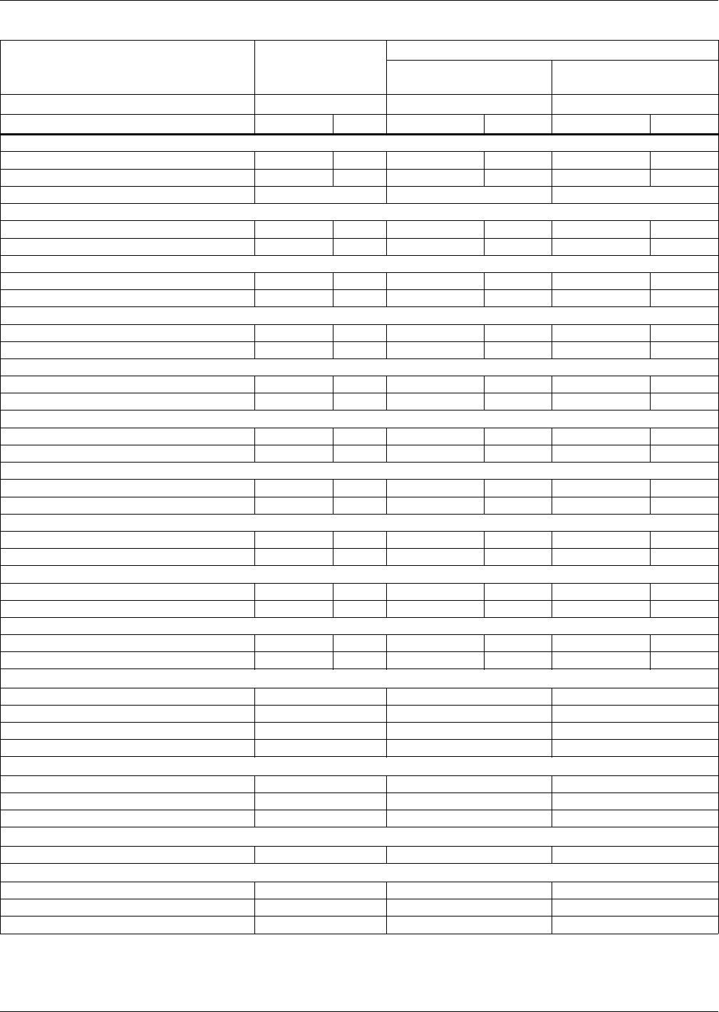
System Data
26
Table 4 Liebert Challenger ITR air-cooled data—50 Hz
System Type
BR = Horizontal Flow
Self-Contained
Split Systems
w/Outdoor Prop-Fan
Condensing Unit
w/Indoor Centrifugal
Condensing Unit
Indoor Unit BR 065A BR 059E BR 059E
Net Capacity Data kW BTU/H kW BTU/H kW BTU/H
37.8°C DB, 21.1°C WB (100°F DB, 70°F WB) 20% RH
Total 22.4 76,300 25.8 87,900 21.0 71,800
Sensible 22.4 76,300 25.8 87,900 21.0 71,800
Non Standard Flow Rates 2300 CFM 2100 CFM
35°C DB, 20.2°C WB (95°F DB, 68.3°F WB) 24% RH
Total 22.0 75,100 24.3 83,100 21.3 72,600
Sensible 22.0 75,100 24.3 83,100 21.3 72,600
32.2°C DB, 19.2°C WB (90°F DB, 66.5°F WB) 28% RH
Total 20.9 71,200 23.0 78,400 20.2 68,800
Sensible 20.9 71,200 23.0 78,400 20.2 68,800
29.4°C DB, 18°C WB (85°F DB, 64.4°F WB) 32% RH
Total 19.7 67,200 21.6 73,800 19.1 65,100
Sensible 19.7 67,200 21.6 73,800 19.1 65,100
26.7°C DB, 17.1°C WB (80°F DB, 62.7°F WB) 38% RH
Total 18.6 63,600 20.3 69,300 18.0 61,400
Sensible 18.6 63,600 20.3 69,300 18.0 61,400
26.7°C DB, 19.2°C WB (80°F DB, 66.5°F WB) 50% RH
Total 19.0 64,900 21.3 72,600 18.3 62,400
Sensible 15.2 51,800 16.0 54,700 14.9 50,900
23.9°C DB, 16.9°C WB (75°F DB, 62.5°F WB) 50% RH
Total 17.8 60,600 19.5 66,600 17.0 58,100
Sensible 14.7 50,300 15.5 52,800 14.4 49,300
23.9°C DB, 16.2°C WB (75°F DB, 61.1°F WB) 45% RH
Total 17.3 59,100 19.0 64,700 16.6 56,700
Sensible 15.8 54,000 16.5 56,300 15.5 53,000
22.2°C DB, 15.6°C WB (72°F DB, 60.1°F WB) 50% RH
Total 17.0 58,100 18.6 63,600 16.3 55,700
Sensible 14.4 49,300 15.1 51,700 14.2 48,300
22.2°C DB, 14.8°C WB (72°F DB, 58.7°F WB) 45% RH
Total 16.7 56,900 18.0 61,500 16.3 55,700
Sensible 15.5 52,900 16.1 54,900 16.3 55,700
Fan Data (Blower A12x9AT)**
Standard Air, CMH (CFM) 4420 (2600) 4420 (2600) 4420 (2600)
Standard Fan Motor, kW (hp) 1.1 (1-1/2) 1.1 (1-1/2) 1.1 (1-1/2)
Opt Fan Motor, kW (hp) 1.5 (2) 1.5 (2) 1.5 (2)
Ext Static, Pa (in. WG) 75 (.3) 75 (.3) 75 (.3)
Evaporator Coil (V-Frame, at Standard Conditions)
Face Area, m2 (ft.2) .62 (6.67) .62 (6.67) .62 (6.67)
Rows 4 4 4
Face Velocity, m/s (FPM) 1.9 (375) 1.9 (375) 1.9 (375)
Electric Reheat 2 Stage (Stainless Steel, Fin Tubular) - Standard
Capacity, element kW (inc. motor heat, BTU/H) 15 (56,200) 15 (56,200) 15 (56,200)
Hot Water Reheat 82.2°C (180°F) EWT, 23.9°C (75°F) EAT - Opt. (inc. standard air volume and optional fan motor hp)
Capacity, inc. motor heat, kW (BTU/H) 25.3 (86,200) 25.3 (86,200) 25.3 (86,200)
Flow Rate, l/s (GPM) .32 (5.0) .32 (5.0) .32 (5.0)
Pressure drop, kPa (ft.) 50.4 (16.9) 50.4 (16.9) 50.4 (16.9)
* The net capacity data has fan motor heat factored in for all ratings and the entering air condition of 72°F (22.2°C) and 50% RH is the
standard rating for ASHRAE 127-2001.All capacities are nominal values; actual performance will be ±5%.
** Data rated with 2" 20% ASHRAE filter. Some options or combinations of options may result in reduced airflow. Consult factory for
recommendations.
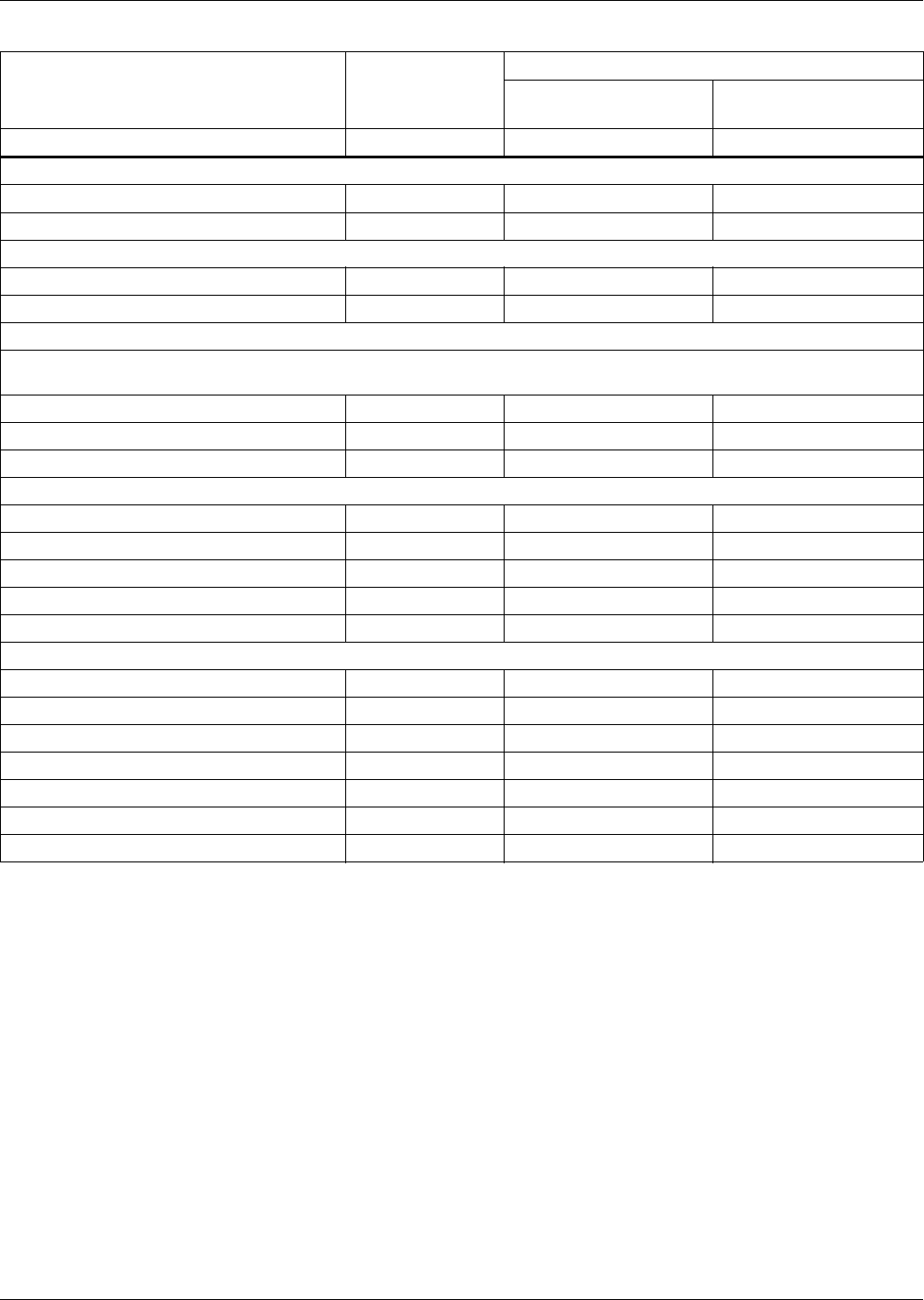
System Data
27
Table 5 Liebert Challenger ITR air-cooled data—50Hz (continued)
System Type
Self-Contained
Split Systems
w/Outdoor Prop-Fan
Condensing Unit
w/Indoor Centrifugal
Condensing Unit
Indoor Unit BR 065A BR 059E BR 059E
Infrared Humidifier - Standard
Capacity - kg/hr (lb/hr) 5 (11) 5 (11) 5 (11)
kW 4.8 4.8 4.8
Steam Generating Humidifier - Optional
Capacity - kg/hr (lb/hr) 5 (11) 5 (11) 5 (11)
kW 3.9 3.9 3.9
Filter Section - Efficiencies per ASHRAE 52.1 - Disposable Type
20% efficiencies available in 51mm (2") - Standard, or optional 102mm (4") depths; other optional 102mm (4") efficiencies
are: 30%, 40-45%, 60-65%
Nominal Size - mm 724 x 749 724 x 749 724 x 749
Nominal Size - inches 28.5 x 29.5 28.5 x 29.5 28.5 x 29.5
Effective Surface Area - m2 (ft2) 2.2 (24.1) 2.2 (24.1) 2.2 (24.1)
Connection Sizes Challenger ITR Unit
Liquid Line 1/2 OD Cu 1/2 OD Cu 1/2 OD Cu
Hot Gas Line 7/8 OD Cu N/A N/A
Suction Line N/A 1 1/8 CD Cu 1 1/8 CD Cu
Humidifier Supply Line 1/4 OD Cu 1/4 OD Cu 1/4 OD Cu
Condensate Drain Line 1/2 FPT 1/2 FPT 1/2 FPT
Condenser Air 35°C (95°F) Ambient
Model CSF104 PFH066A_ _H MC_64A
Motor kW (hp) .56 (3/4) .56 (3/4) 1.5 (2)
Ext. Static Pa (in. WG) N/A N/A 125 (0.5)
CMH (CFM) 8750 (5150) 9854 (5800) 5947 (3500)
Liquid Line Connection 5/8 OD Cu 1/2 OD Cu* 1/2 OD Cu*
Hot Gas Connection 1-1/8 OD Cu N/A N/A
Suction Line Connection N/A 1-1/8 OD Cu* 1-1/8 OD Cu*
* The net capacity data has fan motor heat factored in for all ratings and the entering air condition of 72°F (22.2°C) and 50% RH is the
standard rating for ASHRAE 127-2001.All capacities are nominal values; actual performance will be ±5%.
** Data rated with 2" 20% ASHRAE filter. Some options or combinations of options may result in reduced airflow. Consult factory for
recommendations.
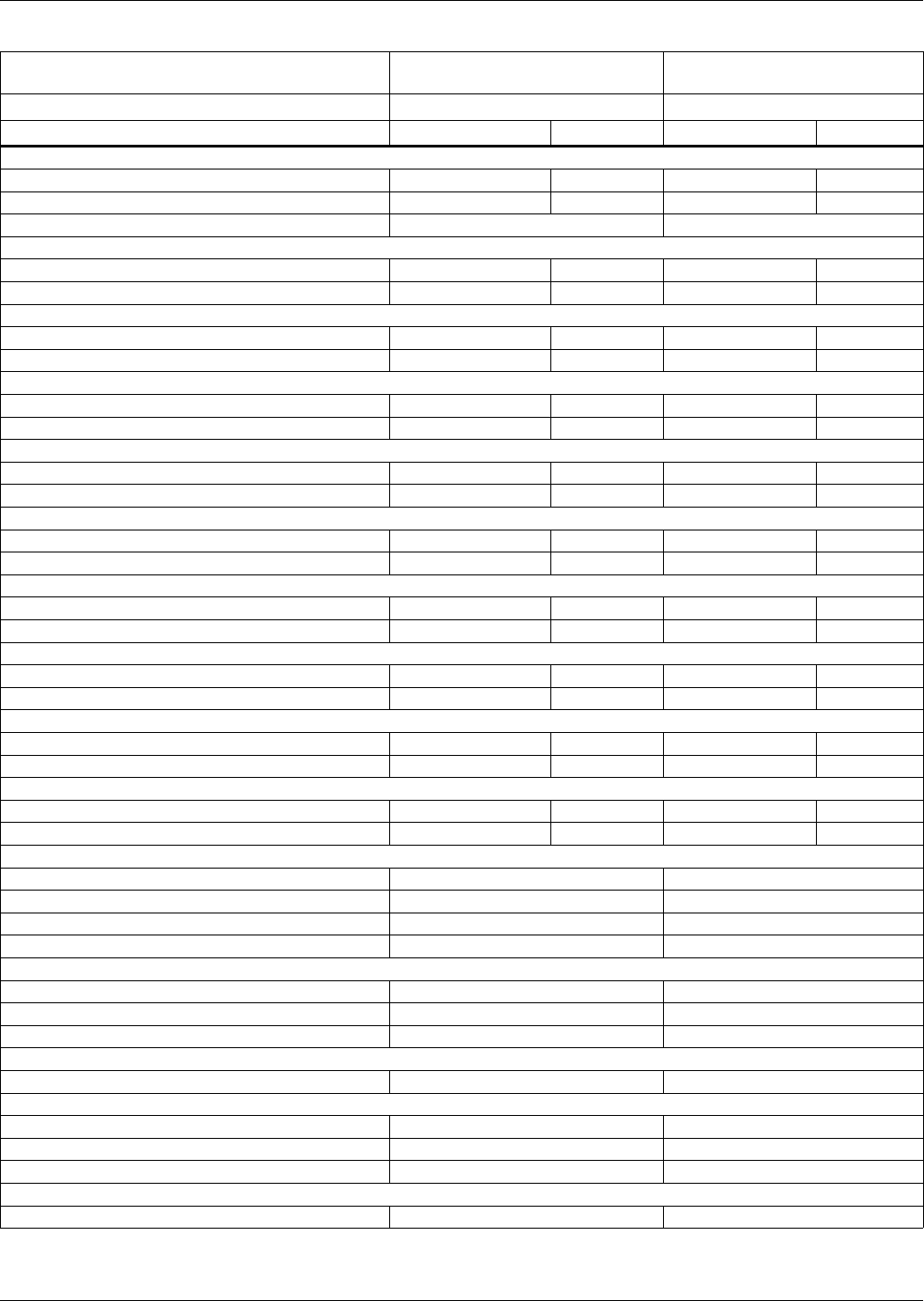
System Data
28
Table 6 Liebert Challenger ITR water cooled data, 60 Hz
System Type
BR = Horizontal Flow Self-Contained Split Systems
Indoor Unit BR 071WG BR 060E
Net Capacity Data BTU/H kW BTU/H kW
100°F DB, 70°F WB (37.8°C DB, 21.1°C WB) 20% RH
Total 82,900 24.3 79,000 23.1
Sensible 82,900 24.3 79,000 23.1
Non-Standard Flow Rates 2600 CFM 2400 CFM
95°F DB, 68.3°F WB (35°C DB, 20.2°C WB) 24% RH
Total 80,400 23.6 78,400 23.0
Sensible 80,400 23.6 78,400 23.0
90°F DB, 66.5°F WB (32°C DB, 19.2°C WB) 28% RH
Total 76,200 22.3 74,400 21.8
Sensible 76,200 22.3 74,400 21.8
85°F DB, 64.4°F WB (29.4°C DB, 18°C WB) 32% RH
Total 72,300 21.2 70,300 20.6
Sensible 72,300 21.2 70,300 20.6
80°F DB, 62.7°F WB (26.7°C DB, 17.1°C WB) 38% RH
Total 68,400 20.0 66,500 19.5
Sensible 68,400 20.0 66,500 19.5
80°F DB, 66.5°F WB (26.7°C DB, 19.2°C WB) 50% RH
Total 69,900 20.5 67,600 19.8
Sensible 55,700 16.3 54,900 16.1
75°F DB, 62.5°F WB (23.9°C DB, 16.9°C WB) 50% RH
Total 65,200 19.1 63,100 18.5
Sensible 54,000 15.8 53,200 15.6
75°F DB, 61.1°F WB (23.9°C DB, 16.2°C WB) 45% RH
Total 63,600 18.6 61,500 18.0
Sensible 58,000 17.0 57,100 16.7
72°F DB, 60.1°F WB (22.2°C DB, 15.6°C WB) 50% RH
Total 62,500 18.3 60,500 17.7
Sensible 53,000 15.5 52,100 15.3
72°F DB, 58.7°F WB (22.2°C DB, 14.8°C WB) 45% RH
Total 61,100 17.9 59,200 17.3
Sensible 56,700 16.6 55,900 16.4
Fan Data (Blower A12x9AT)**
Standard Air, CFM (CMH) 2800 (4760) 2800 (4760)
Standard Fan Motor, hp (kW) 1-1/2 (1.1) 1-1/2 (1.1)
Opt Fan Motor, hp (kW) 2 (1.5) 2 (1.5)
Ext Static, in. WG (Pa) .3 (75) .3 (75)
Evaporator Coil (V-Frame, at standard conditions)
Face Area, ft.2 (m2) 6.67 (.62) 6.67 (.62)
Rows 4 4
Face Velocity, FPM (m/s) 405 (2.1) 405 (2.1)
Electric Reheat 2 Stage (Stainless Steel, Fin Tubular) - Standard
Capacity, inc. motor heat, BTU/H (element kW) 56,200 (15) 56,200 (15)
Hot Water Reheat 180°F (82.2°C) EWT, 75°F (23.9°C) EAT - Optional (includes std air volume and opt fan motor hp)
Capacity, inc. motor heat, BTU/H (kW) 88,700 (26.0) 88,700 (26.0)
Flow Rate, GPM (l/s) 5.0 (.32) 5.0 (.32)
Pressure drop, ft. (kPa) 16.9 (50.4) 16.9 (50.4)
Hot Gas Reheat - Optional (Includes standard air volume and optional fan motor)
Capacity, inc. motor heat, BTU/H (kW) 54,900 (16.1) 54,900 (16.1)
* The net capacity data has fan motor heat factored in for all ratings and the entering air condition of 72°F (22.2°C) and 50% RH is the standard rating for
ASHRAE 127-2001.All capacities are nominal values; actual performance will be ±5%.
** Data rated with 2" 20% ASHRAE filter. Some options or combinations of options may result in reduced airflow. Consult factory for recommendations.
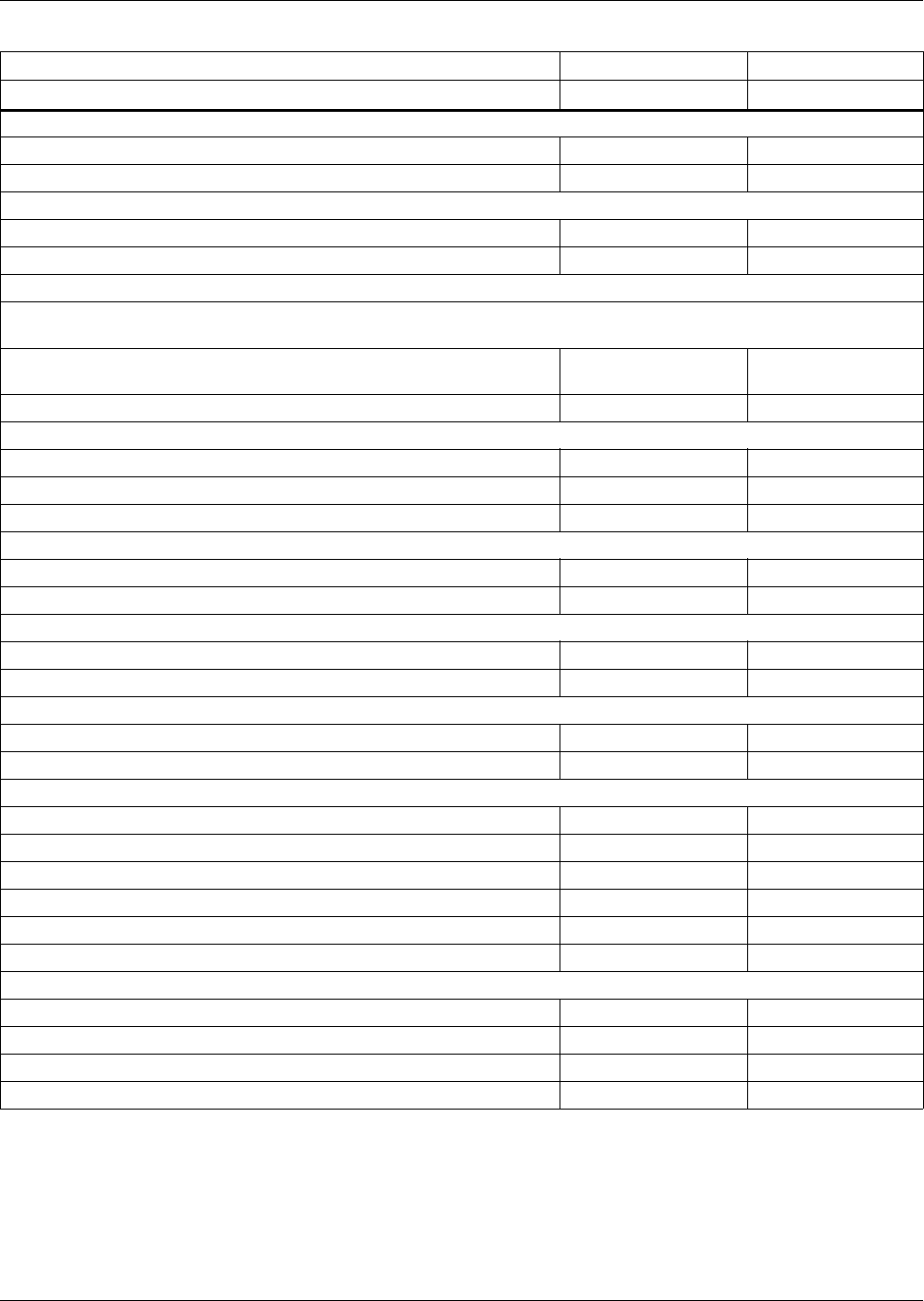
System Data
29
Table 7 Liebert Challenger ITR water cooled data, 60 Hz (continued)
System Type Self-Contained Split Systems
Indoor Unit BR 071WG BR 060E
Infrared Humidifier - Standard
Capacity, lb/hr (kg/hr) 11 (5) 11 (5)
kW 4.8 4.8
Steam Generating Humidifier - Optional
Capacity, lb/hr (kg/hr) 11 (5) 11 (5)
kW 3.9 3.9
Filter Section - Efficiencies per ASHRAE 52.1 - Disposable Type
20% efficiencies available in 2" (51mm) - Standard, or optional 4" (102mm) depths; other optional 4" (102mm) efficiencies
are: 30%, 40-45%, 60-65%
Nominal Size, in. (mm) 28.5 x 29.5
(724 x 749)
28.5 x 29.5
(724 x 749)
Effective Surface Area, ft2 (m2) 24.1 (2.2) 24.1 (2.2)
Water Regulating Valve
Size, in. 1 1
Water Requirements (Coaxial Condenser) MC_69W
THR - BTU/H (kW) @ 75°F (22.2°C), 50% RH 82,000 (24.0) 81100 (23.8)
65°F (18.3°C) EWT - 105°F (40.6°C) Cond Temp
Flow Rate, GPM (l/s) 5.4 (.34) 5.4 (.34)
Pressure Drop, PSI (kPa) 0.9 (6.2) 1.2 (8.1)
75°F (23.9°C) EWT - 105°F (40.6°C) Cond Temp
Flow Rate, GPM (l/s) 7.7 (.49) 7.6 (.48)
Pressure Drop, PSI (kPa) 1.6 (11.0) 2.2 (15.2)
85°F (29.4°C) EWT - 115°F (46.1°C) Cond Temp
Flow Rate, GPM (l/s) 9.9 (.62) 9.7 (.61)
Pressure Drop, PSI (kPa) 2.5 (17.2) 3.5 (24.2)
Connection Sizes Challenger ITR Unit
Condenser Supply 1-1/8 OD Cu
Condenser Return 1-1/8 OD Cu
Liquid Line 1/2 OD Cu
Suction Line 1 1/8 CD Cu
Humidifier Supply Line 1/4 OD Cu 1/4 OD Cu
Condensate Drain Line 1/2 FPT 1/2 FPT
Connection Sizes Remote Condensing Unit
Condenser Supply 1-1/8 OD Cu
Condenser Return 1-1/8 OD Cu
Liquid Line 1/2 OD Cu
Suction Line 1-1/8 OD Cu
Self-contained unit pressure drops based on two-way valve with bypass. Split system unit pressure drops based on two-way or three-way
valve.
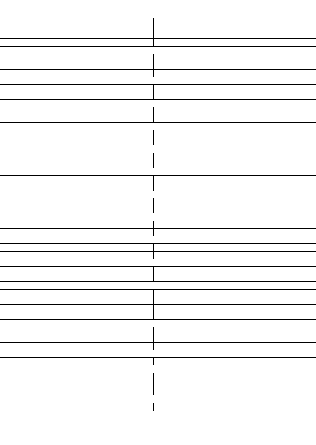
System Data
30
Table 8 Liebert Challenger ITR water cooled data, 50 Hz
System Type
BR = Horizontal Flow Self-Contained Split Systems
Indoor Unit BR 070WG BR 059E
Net Capacity Data kW BTU/H kW BTU/H
37.8ºC DB, 21.1ºC WB (100ºF DB, 70ºF WB) 20% RH
Total 24.0 81,800 23.1 78,800
Sensible 24.0 81,800 23.1 78,800
Non Standard Flow Rates 2500 CFM 2400 CFM
35ºC DB, 20.2ºC WB (95ºF DB, 68.3ºF WB) 24% RH
Total 23.0 78,500 22.4 76,500
Sensible 23.0 78,500 22.4 76,500
32.2ºC DB, 19.2ºC WB (90ºF DB, 66.5ºF WB) 28% RH
Total 21.8 74,300 21.2 72,400
Sensible 21.8 74,300 21.2 72,400
29.4ºC DB, 18ºC WB (85ºF DB, 64.4ºF WB) 32% RH
Total 20.6 70,200 20.0 68,300
Sensible 20.6 70,200 20.0 68,300
26.7ºC DB, 17.1ºC WB (80ºF DB, 62.7ºF WB) 38% RH
Total 19.4 66,200 18.9 64,500
Sensible 19.4 66,200 18.9 64,500
26.7ºC DB, 19.2ºC WB (80ºF DB, 66.5ºF WB) 50% RH
Total 20.0 68,400 19.4 66,100
Sensible 15.6 53,100 15.3 52,300
23.9ºC DB, 16.9ºC WB (75ºF DB, 62.5ºF WB) 50% RH
Total 18.6 63,500 18.0 61,400
Sensible 15.1 51,500 14.8 50,600
23.9ºC DB, 16.2ºC WB (75ºF DB, 61.1ºF WB) 45% RH
Total 18.1 61,800 17.5 59,800
Sensible 16.1 55,100 15.9 54,300
22.2ºC DB, 15.6ºC WB (72ºF DB, 60.1ºF WB) 50% RH
Total 17.8 60,700 17.2 58,700
Sensible 14.8 50,400 14.5 49,600
22.2ºC DB, 14.8ºC WB (72ºF DB, 58.7ºF WB) 45% RH
Total 17.3 59,200 16.8 57,400
Sensible 15.8 53,900 15.6 53,100
Fan Data (Blower A12x9AT)**
Standard Air, CMH (CFM) 4420 (2600) 4420 (2600)
Standard Fan Motor, kW (hp) 1.1 (1-1/2) 1.1 (1-1/2)
Opt Fan Motor, kW (hp) 1.5 (2) 1.5 (2)
Ext Static Pa, (in. WG) 75 (.3) 75 (.3)
Evaporator Coil (V-Frame, at standard conditions)
Face Area, m2 (ft.2) .62 (6.67) .62 (6.67)
Rows 4 4
Face Velocity, m/s (FPM) 1.9 (375) 1.9 (375)
Electric Reheat 2 Stage (Stainless Steel, Fin Tubular) - Standard
Capacity, element kW (inc. motor heat, BTU/H) 15 (56,200) 15 (56,200)
Hot Water Reheat 82.2°C (180°F) EWT, 23.9°C (75°F) EAT - Optional (includes std air volume and opt fan motor hp)
Capacity, inc. motor heat, kW (BTU/H) 25.3 (86,200) 25.3 (86,200)
Flow Rate, l/s (GPM) .32 (5.0) .32 (5.0)
Pressure drop, kPa (ft.) 50.4 (16.9) 50.4 (16.9)
Hot Gas Reheat - Optional (includes standard air volume and optional fan motor)
Capacity, inc. motor heat, kW (BTU/H) 15.0 (51,300) 15.0 (51,300)
* The net capacity data has fan motor heat factored in for all ratings and the entering air condition of 72°F (22.2°C) and 50% RH is the
standard rating for ASHRAE 127-2001.All capacities are nominal values; actual performance will be ±5%.
** Data rated with 2" 20% ASHRAE filter. Some options or combinations of options may result in reduced airflow. Consult factory for
recommendations.
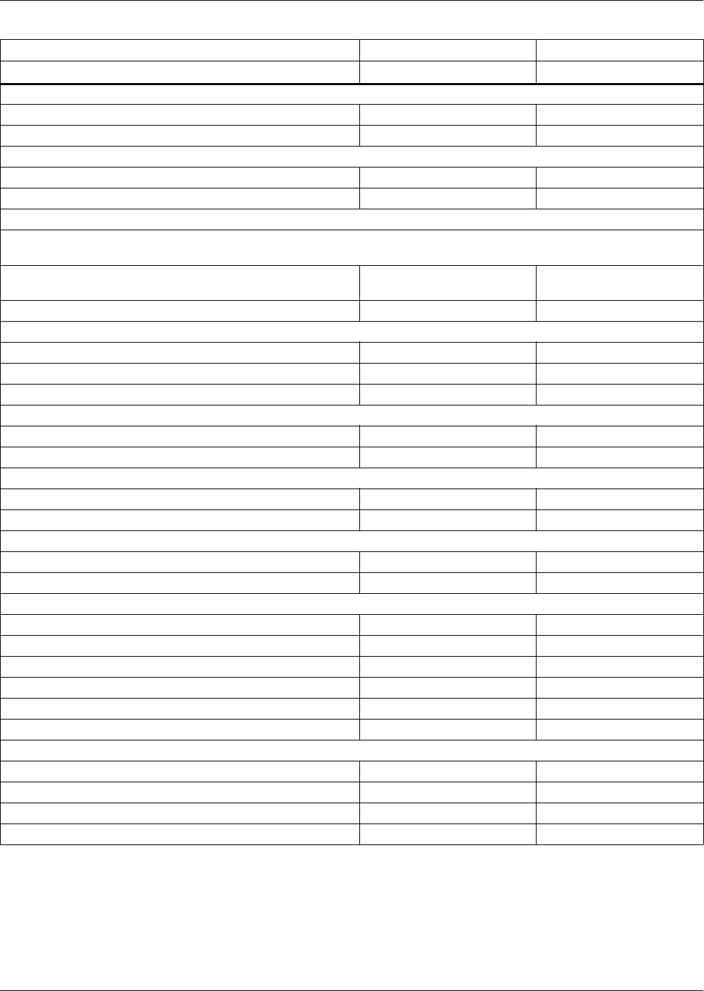
System Data
31
Table 9 Liebert Challenger ITR water cooled data, 50 Hz (continued)
System Type Self-Contained Split Systems
Indoor Unit BR 070WG BR 059E
Infrared Humidifier - Standard
Capacity - kg/hr (lb/hr) 5 (11) 5 (11)
kW 4.8 4.8
Steam Generating Humidifier - Optional
Capacity, kg/hr (lb/hr) 5 (11) 5 (11)
kW 3.9 3.9
Filter Section - Efficiencies per ASHRAE 52.1 - Disposable Type
20% efficiencies available in 51mm (2") - Standard, or optional 102mm (4") depths; other optional 102mm (4") efficiencies
are: 30%, 40-45%, 60-65%
Nominal Size, mm (in.) 724 x 749
(28.5 x 29.5)
724 x 749
(28.5 x 29.5)
Effective Surface Area, m2 (ft2) 2.2 (24.1) 2.2 (24.1)
Water Regulating Valve
Size, in 1 1
Water Requirements (Coaxial Condenser) MC_68W
THR - kW (BTU/H) @ 22.2°C (75°F), 50% RH 23.8 (81,200) 23.2 (79,200)
18.3°C (65°F) EWT - 40.6°C (105°F) Cond Temp
Flow Rate, l/s (GPM) .34 (5.4) .33 (5.2)
Pressure Drop, kPa (PSI) 5.7 (0.8) 7.8 (1.1)
23.9°C(75°F) EWT - 40.6°C (105°F) Cond Temp
Flow Rate, l/s (GPM) .48 (7.6) .47 (7.4)
Pressure Drop, kPa (PSI) 10.7 (1.6) 14.3 (2.1)
29.4°C (85°F) EWT - 46.1°C (115°F) Cond Temp
Flow Rate, l/s (GPM) .61 (9.7) .59 (9.4)
Pressure Drop, kPa (PSI) 16.7 (2.4) 22.7 (3.3)
Connection Sizes Challenger ITR Unit
Condenser Supply 1-1/8 OD Cu —
Condenser Return 1-1/8 OD Cu —
Liquid Line — 1/2 OD Cu
Suction Line — 1-1/8 CD Cu
Humidifier Supply Line 1/4 OD Cu 1/4 OD Cu
Condensate Drain Line 1/2 FPT 1/2 FPT
Connection Sizes Remote Condensing Unit
Condenser Supply — 1-1/8 OD Cu
Condenser Return — 1-1/8 OD Cu
Liquid Line — 1/2 OD Cu
Suction Line — 1-1/8 CD Cu
Self-contained unit pressure drops based on two-way valve with bypass. Split system unit pressure drops based on two-way or three-way
valve.
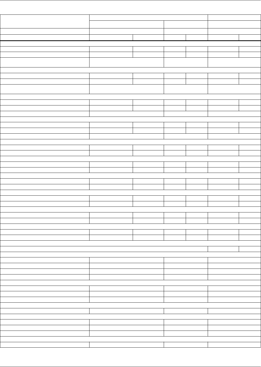
System Data
32
Table 10 Liebert Challenger ITR glycol cooled data, 60 Hz
System Type
BR = Horizontal Flow
BM = Horizontal Flow with Econ-O-Coil
Glycol Cooled GLYCOOL
Self-Contained Split Systems Self Contained
Indoor Unit BR 071WG BR 060E BM 061G
Net Capacity Data BTU/H kW BTU/H kW BTU/H kW
100°F DB, 70°F WB (37.8°C DB, 21.1°C WB) 20% RH
Total 69,800 20.5 71,600 21.0 66,000 19.3
Sensible 69,800 20.5 71,600 21.0 66,000 19.3
Non Standard Flow Rates 1800 CFM, 21.5 GPM,
27.4 FT PD 2100 CFM 2600 CFM, 20.5 GPM,
24.6 FT PD
95°F DB, 68.3°F WB (35°C DB, 20.2°C WB) 24% RH
Total 68,600 20.1 72,300 21.2 64,700 19.0
Sensible 68,600 20.1 72,300 21.2 64,700 19.0
Non Standard Flow Rates 2100 CFM, 21.5 GPM,
27.4 FT PD 2600 CFM 2300 CFM, 19.5 GPM,
22.5 FT PD
90°F DB, 66.5°F WB (32°C DB, 19.2°C WB) 28% RH
Total 64,700 19.0 69,900 20.5 65,300 19.1
Sensible 64,700 19.0 69,900 20.5 65,300 19.1
Non Standard Flow Rates 2100CFM,18.5 GPM, 20.9FT PD 19.5 GPM, 22.5 FT PD
85°F DB, 64.4°F WB (29.4°C DB, 18°C WB) 32% RH
Total 62,800 18.4 66,200 19.4 61,500 18.0
Sensible 62,800 18.4 66,200 19.4 61,500 18.0
Non Standard Flow Rates 2300 CFM
80°F DB, 62.7°F WB (26.7°C DB, 17.1°C WB) 38% RH
Total 62,400 18.3 62,500 18.3 58,200 17.1
Sensible 62,400 18.3 62,500 18.3 58,200 17.1
80°F DB, 66.5°F WB (26.7°C DB, 19.2°C WB) 50% RH
Total 62,900 18.4 63,000 18.5 59,900 17.6
Sensible 53,200 15.6 53,200 15.6 51,200 15.0
75°F DB, 62.5°F WB (23.9°C DB, 16.9°C WB) 50% RH
Total 58,900 17.3 58,800 17.2 55,900 16.4
Sensible 51,500 15.1 51,500 15.1 49,500 14.5
75°F DB, 61.1°F WB (23.9°C DB, 16.2°C WB) 45% RH
Total 59,000 17.3 59,000 17.3 55,000 16.1
Sensible 59,000 17.3 59,000 17.3 55,000 16.1
72°F DB, 60.1°F WB (22.2°C DB, 15.6°C WB) 50% RH
Total 56,500 16.6 56,500 16.6 53,600 15.7
Sensible 50,500 14.8 50,500 14.8 48,500 14.2
72°F DB, 58.7°F WB (22.2°C DB, 14.8°C WB) 45% RH
Total 56,900 16.7 56,900 16.7 53,000 15.5
Sensible 56,900 16.7 56,900 16.7 53,000 15.5
GLYCOOL Coil Sensible Capacity
75°F DB, 62.5°F WB (23.9°C DB, 16.9°C WB) 45°F (7.2°C) EGT 47,700 14.0
Fan Data (Blower A12x9AT)**
Standard Air, CFM (CMH) 2800 (4760) 2800 (4760) 2800 (4760)
Standard Fan Motor, hp (kW) 1-1/2 (1.1) 1-1/2 (1.1) 2 (1.5)
Opt Fan Motor, hp (kW) 2 (1.5) 2 (1.5) N/A
Ext Static, in. WG (Pa) .3 (75) .3 (75) .3 (75)
Evaporator Coil (V-Frame, at standard conditions)
Face Area, ft.2 (m2) 6.67 (.62) 6.67 (.62) 6.67 (.62)
Rows 4 4 4
Face Velocity, FPM (m/s) 405 (2.1) 405 (2.1) 405 (2.1)
Electric Reheat 2 Stage (Stainless Steel, Fin Tubular) - Standard
Capacity, inc. motor heat, BTU/H(element kW) 56,200 (15) 56,200 (15) 57,700 (15)
Hot Water Reheat 180°F (82.2°C) EWT, 75°F (23.9°C) EAT - Optional (includes standard air volume and optional fan motor hp)
Capacity, inc. motor heat, BTU/H(kW) 88,700 (26.0) 88,700 (26.0) N/A
Flow Rate, GPM (l/s) 5.0 (.32) 5.0 (.32) 5.0 (.32)
Pressure drop, ft. (kPa) 16.9 (50.4) 16.9 (50.4) 16.9 (50.4)
Hot Gas Reheat - Optional (includes standard air volume and optional fan motor)
Capacity, inc. motor heat, BTU/H (kW) 54,900 (16.1) 54,900 (16.1) N/A
* The net capacity data has fan motor heat factored in for all ratings and the entering air condition of 72°F (22.2°C) and 50% RH is the standard rating for
ASHRAE 127-2001.All capacities are nominal values; actual performance will be ±5%. All above data is based on 40% ethylene glycol solution.
** Data rated with 2" 20% ASHRAE filter. Some options or combinations of options may result in reduced airflow. Consult factory for recommendations.
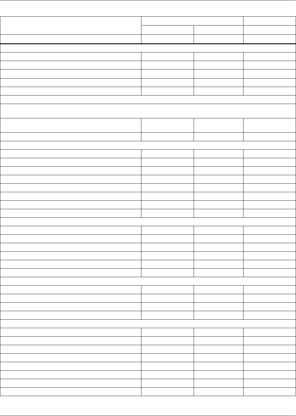
System Data
33
Table 11 Liebert Challenger ITR glycol cooled data, 60 Hz (continued)
System Type
Glycol Cooled GLYCOOL
Self-Contained Split Systems Self-Contained
Indoor Unit BR 071WG BR 060E BM 061G
Infrared Humidifier - Standard
Capacity, lb/hr (kg/hr) 11 (5) 11 (5) 11 (5)
kW 4.8 4.8 4.8
Steam Generating Humidifier - Optional
Capacity, lb/hr (kg/hr) 11 (5) 11 (5) 11 (5)
kW 3.9 3.9 3.9
Filter Section - Efficiencies per ASHRAE 52.1 - Disposable Type
20% efficiencies available in 2" (51mm) - Standard, or optional 4" (102mm) Depths; other optional 4" (102mm) efficiencies
are: 30%, 40-45%, 60-65%
Nominal Size, inches (mm) 28.5 x 29.5
(724 x 749)
28.5 x 29.5
(724 x 749)
28.5 x 29.5
(724 x 749)
Effective Surface Area, ft2 (m2) 24.1 (2.2) 24.1 (2.2) 24.1 (2.2)
Glycol Regulating Valve
Size, in111
Econ-O-Valve
Size, in — — 1
Cv — — 13.9
System Data* MC_*69WG
Flow Rate, GPM (l/s) 17.5 (1.1) 20 (1.3) 17.5 (1.1)
Unit Volume, gal (l) 2.0 (7.5) 2.0 (7.5) 4.0 (15.0)
Pressure Drop, ft. (kPa) 18.9 (56.4) 37.5 (111.9) 51.1 (152.5)
Connection Sizes Challenger ITR Unit
Condenser Supply 1-1/8 OD Cu 1-1/8 OD Cu
Condenser Return 1-1/8 OD Cu 1-1/8 OD Cu
Liquid Line 1/2 OD Cu
Suction Line 1-1/8 OD Cu
Humidifier Supply Line 1/4 OD Cu 1/4 OD Cu 1/4 OD Cu
Condensate Drain Line 1/2 FPT 1/2 FPT 1/2 FPT
Connection Sizes Condensing Unit
Condenser Supply 1-1/8 OD Cu
Condenser Return 1-1/8 OD Cu
Liquid Line 1/2 OD Cu
Suction Line 1-1/8 OD Cu
Drycooler 95°F (35°C) Ambient*
Model Number DSF112-3PH DSO174-3PH DSO112-3PH
Drycooler Connections 2 2 2
Volume, gal. (l) 5.8 (22.0) 6.9 (26.2) 5.8 (22.0)
Pressure Drop, ft. (kPa) 2.4 (7.2) 3.1 (9.2) 2.4 (7.2)
Fan, hp (kW) 3/4 (.56) 3/4 (.56) 3/4 (.56)
Glycol Pump, 3-phase hp (kW) 3/4 (.56) 3/4 (.56) 1.5 (1.1)
Head, ft. (kPa) 69 (205.9) 69 (205.9) 88 (262.6)
Pump Suction and Discharge NPT, female 1-1/4 & 3/4 1-1/4 & 3/4 1-1/4 & 3/4
* All data above is based on 40% ethylene glycol solution.
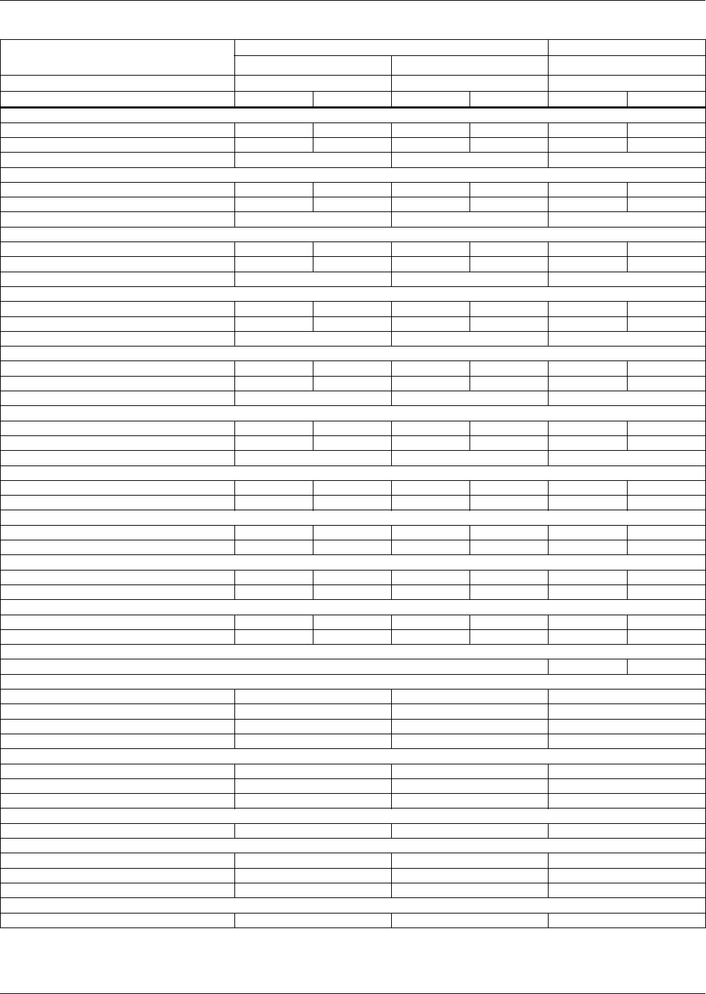
System Data
34
Table 12 Liebert Challenger ITR glycol cooled data, 50 Hz
System Type
BR = Horizontal Flow
BM = Horizontal Flow with Econ-O-Coil
Glycol Cooled GLYCOOL
Self-Contained Split Systems Self Contained
Indoor Unit BR 070WG BR 059E BM 058G
Net Capacity Data kW BTU/H kW BTU/H kW BTU/H
37.8ºC DB, 21.1ºC WB (100ºF DB, 70ºF WB) 20% RH
Total 20.3 69,300 20.8 70,900 18.8 64,100
Sensible 20.3 69,300 20.8 70,900 18.8 64,100
Non Standard Flow Rates 1900 CFM, 24.5 GPM 2100 CFM 2000 CFM, 22.5 GPM
35ºC DB, 20.2ºC WB (95ºF DB, 68.3ºF WB) 24% RH
Total 19.6 66,800 20.7 70,800 17.8 60,600
Sensible 19.6 66,800 20.7 70,800 17.8 60,600
Non Standard Flow Rates 2000 CFM, 23.5 GPM 2500 CFM 2000 CFM, 20.5 GPM
32.2ºC DB, 19.2ºC WB (90ºF DB, 66.5ºF WB) 28% RH
Total 18.5 63,000 19.9 67,800 16.8 57,300
Sensible 18.5 63,000 19.9 67,800 16.8 57,300
Non Standard Flow Rates 2000 CFM, 21.5 GPM 2000 CFM
29.4ºC DB, 18ºC WB (85ºF DB, 64.4ºF WB) 32% RH
Total 17.9 61,200 18.8 64,200 16.9 57,700
Sensible 17.9 61,200 18.8 64,200 16.9 57,700
Non Standard Flow Rates 2200 CFM, 19.5 GPM 2400 CFM
26.7ºC DB, 17.1ºC WB (80ºF DB, 62.7ºF WB) 38% RH
Total 17.1 58,400 17.7 60,500 16.4 55,900
Sensible 17.1 58,400 17.7 60,500 16.4 55,900
Non Standard Flow Rates 2300 CFM
26.7ºC DB, 19.2ºC WB (80ºF DB, 66.5ºF WB) 50% RH
Total 17.2 58,800 18.0 61,400 16.8 57,400
Sensible 12.7 43,200 14.8 50,500 13.5 46,000
Non Standard Flow Rates 2000 CFM 2400 CFM
23.9ºC DB, 16.9ºC WB (75ºF DB, 62.5ºF WB) 50% RH
Total 16.7 57,000 16.8 57,200 15.9 54,100
Sensible 14.3 48,800 14.3 48,900 13.7 46,800
23.9ºC DB, 16.2ºC WB (75ºF DB, 61.1ºF WB) 45% RH
Total 16.7 56,900 16.3 55,800 15.4 52,700
Sensible 16.7 56,900 15.4 52,600 15.4 52,700
22.2ºC DB, 15.6ºC WB (72ºF DB, 60.1ºF WB) 50% RH
Total 16.0 54,600 16.1 54,800 15.2 51,800
Sensible 14.0 47,900 14.0 47,900 13.4 45,800
22.2ºC DB, 14.8ºC WB (72ºF DB, 58.7ºF WB) 45% RH
Total 16.1 54,800 16.1 55,000 14.9 50,700
Sensible 16.1 54,800 16.1 55,000 14.9 50,700
GLYCOOL Coil Sensible Capacity
23.9°C DB, 16.9°C WB (75°F DB, 62.5°C WB) 10°C (45°F) EGT 14 47,700.0
Fan Data (Blower A12x9AT)**
Standard Air, CMH (CFM) 4420 (2600) 4420 (2600) 4420 (2600)
Standard Fan Motor, kW (hp) 1.1 (1-1/2) 1.1 (1-1/2) 1.5 (2)
Optional Fan Motor, kW (hp) 1.5 (2) 1.5 (2) N/A
Ext Static, Pa (in. WG) 75 (.3) 75 (.3) 75 (.3)
Evaporator Coil (V-Frame, at standard conditions)
Face Area, m2 (ft.2) .62 (6.67) .62 (6.67) .62 (6.67)
Rows 4 4 4
Face Velocity, m/s (FPM) 1.9 (375) 1.9 (375) 1.9 (375)
Electric Reheat 2 Stage (Stainless Steel, Fin Tubular) - Standard
Capacity, element kW (inc. motor heat, BTU/H) 15 (56,200) 15 (56,200) 15 (56,200)
Hot Water Reheat 82.2°C (180°F) EWT, 23.9°C (75°F) EAT - Optional (Includes standard air volume and optional fan motor hp)
Capacity, inc. motor heat, kW (BTU/H) 25.3 (86,200) 25.3 (86,200) 25.3 (86,200)
Flow Rate, l/s (GPM) .32 (5.0) .32 (5.0) .32 (5.0)
Pressure drop, kPa (ft.) 50.4 (16.9) 50.4 (16.9) 50.4 (16.9)
Hot Gas Reheat - Optional (Includes standard air volume and optional fan motor)
Capacity, kW (BTU/H) (includes motor heat) 15.0 (51,300) 15.0 (51,300) 15.0 (51,300)
* The net capacity data has fan motor heat factored in for all ratings and the entering air condition of 72°F (22.2°C) and 50% RH is the standard rating
for ASHRAE 127-2001. All capacities are nominal values; actual performance will be ±5%. All data above is based on 40% ethylene glycol solution.
** Data rated with 2" 20% ASHRAE filter. Some options or combinations of options may result in reduced airflow. Consult factory for
recommendations.
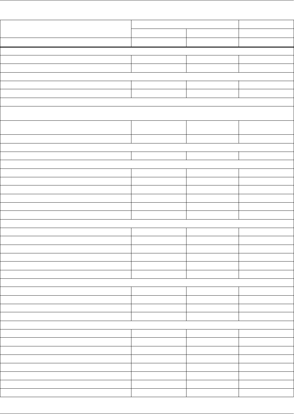
System Data
35
Table 13 Liebert Challenger ITR glycol cooled data, 50 Hz (continued)
System Type Glycol Cooled GLYCOOL
Self-Contained Split Systems Self-Contained
Indoor Unit BR 070WG BR 059E BM 058G
Infrared Humidifier - Standard
Capacity, kg/hr (lb/hr) 5 (11) 5 (11) 5 (11)
kW 4.8 4.8 4.8
Steam Generating Humidifier - Optional
Capacity, kg/hr (lb/hr) 5 (11) 5 (11) 5 (11)
kW 3.9 3.9 3.9
Filter Section - Efficiencies per ASHRAE 52.1 - Disposable Type
20% efficiencies available in 51mm (2") - Standard, or optional 102mm (4") depths; other optional 102mm (4") efficiencies
are: 30%, 40-45%, 60-65%
Nominal Size, mm (in) 724 x 749
(28.5 x 29.5)
724 x 749
(28.5 x 29.5)
724 x 749
(28.5 x 29.5)
Effective Surface Area, m2 (ft2) 2.2 (24.1) 2.2 (24.1) 2.2 (24.1)
Glycol Regulating Valve
Size, in111
Econ-O-Valve
Size, in - - 1
Cv - - 13.9
System Data* MC_68WG
Flow Rate, l/s (GPM) 1.1 (17.5) 1.3 (20) 1.1 (17.5)
Unit Volume, liters (gallons) 7.5 (2.0) 7.5 (2.0) 15.0 (4.0)
Pressure Drop, kPa (ft.) 56.4 (18.9) 111.9 (37.5) 152.5 (51.1)
Connection Sizes Challenger ITR Unit
Condenser Supply 1-1/8 OD Cu 1-1/8 OD Cu
Condenser Return 1-1/8 OD Cu 1-1/8 OD Cu
Liquid Line 1/2 OD Cu
Suction Line 1-1/8 CD Cu
Humidifier Supply Line 1/4 OD Cu 1/4 OD Cu 1/4 OD Cu
Condensate Drain Line 1/2 FPT 1/2 FPT 1/2 FPT
Connection Sizes Condensing Unit
Condenser Supply 1-1/8 OD Cu
Condenser Return 1-1/8 OD Cu
Liquid Line 1/2 OD Cu
Suction Line 1-1/8 CD Cu
Drycooler 35°C (95°F) Ambient*
Model Number DSF112-3PH DSF174-3PH DSF112-3PH
Drycooler Connections 2 2 2
Volume, liters (gallons) 5.8 (22.0) 6.9 (26.2) 5.8 (22.0)
Pressure Drop, kPa (ft.) 7.2 (2.4) 9.2 (3.1) 7.2 (2.4)
Fan, kW (hp) .56 (3/4) .56 (3/4) .56 (3/4)
Glycol Pump - 3-Phase kW (hp) 1.1 (1.5) 1.1 (1.5) 1.1 (1.5)
Head, kPa (ft.) 262.6 (88.0) 262.6 (88.0) 262.6 (88.0)
Pump Suction and Discharge NPT, female 1-1/4 & 3/4 1-1/4 & 3/4 1-1/4 & 3/4
* All data above is based on 40% ethylene glycol solution.
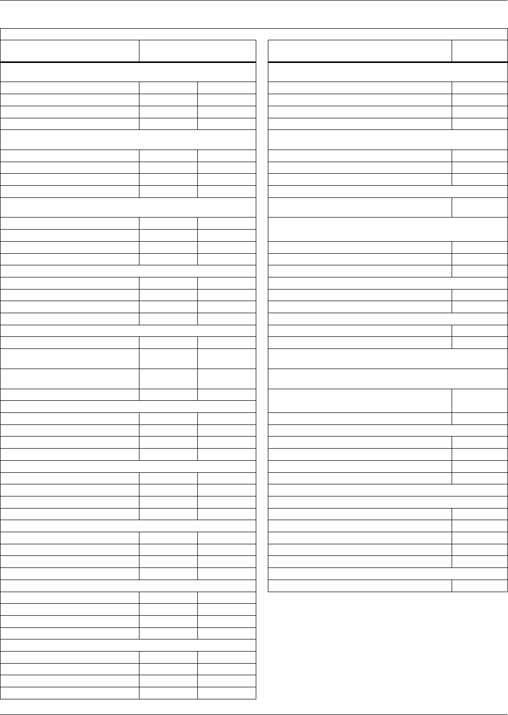
System Data
36
Table 14 Liebert Challenger ITR chilled water data, 60 Hz
Capacity Data BTU/H (kW) @ 45°F (7.2°C) EWT, 10°F (5.6°C) Water Rise; Net Capacity Data
Indoor Unit
BR = Horizontal Flow BR 102C Indoor Unit BR 102C
100ºF DB, 70ºF WB (37.8ºC DB, 21.1ºC WB) 20% RH, 12°F
(6.7°C) Water Rise Fan Data (Blower A12x9AT)**
Total BTU/H (kW) 125,000 36.6 Standard Air, CFM (CMH) 2800 (4760)
Sensible BTU/H (kW) 118,000 34.6 Standard Fan Motor, hp (kW) 1-1/2 (1.1)
Flow Rate GPM (l/s) 21.4 1.4 Opt. Fan Motor, hp (kW) 2 (1.5)
Pressure Drop ft (kPa) 25.5 76.0 Ext Static, in. WG (Pa) .3 (75)
95ºF DB, 68.3ºF WB (35ºC DB, 20.2ºC WB) 24% RH, 12°F
(6.7°C) Water Rise Chilled Water Coil (V-Frame, at standard conditions)
Total BTU/H (kW) 113,000 33.1 Face Area, ft.2 (m2) 6.67 (.62)
Sensible BTU/H (kW) 107,000 31.4 Rows 4
Flow Rate GPM (l/s) 19.6 1.2 Face Velocity, FPM (m/s) 405 (2.1)
Pressure Drop ft (kPa) 21.7 64.7 Electric Reheat 2 Stage (Stainless Steel, Fin Tubular) - Std
90ºF DB, 66.5ºF WB (32.2ºC DB, 19.2ºC WB) 28% RH, 12°F (6.7°C)
Water Rise Capacity, inc. motor heat, BTU/H (element kW) 56,200 (15)
Total BTU/H (kW) 101,000 29.6 Hot Water Reheat 180°F (82.2°C) EWT, 75°F (23.9°C) EAT -
Optional (includes std air volume and opt fan motor hp)
Sensible BTU/H (kW) 94,700 27.7
Flow Rate GPM (l/s) 17.4 1.1 Capacity, inc. motor heat, BTU/H (kW) 88,700 (26.0)
Pressure Drop ft (kPa) 17.4 51.9 Flow Rate, GPM (l/s) 5.0 (.32)
85ºF DB, 64.4ºF WB (29.4ºC DB, 18ºC WB) 32% RH Pressure drop, ft. (kPa) 16.9 (50.4)
Total BTU/H (kW) 91,000 26.7 Infrared Humidifier - Standard
Sensible BTU/H (kW) 85,000 24.9 Capacity, lb/hr (kg/hr) 11 (5)
Flow Rate GPM (l/s) 18.9 1.2 kW 4.8
Pressure Drop ft (kPa) 20.2 60.2 Steam Generating Humidifier - Optional
80ºF DB, 62.7ºF WB (26.7ºC DB, 17.1ºC WB) 38% RH Capacity, lb/hr (kg/hr) 11 (5)
Total BTU/H (kW) 79,000 23.1 kW 3.9
Sensible BTU/H (kW) 72,400 21.2 Filter Section - Efficiencies per ASHRAE 52.1 - Disposable
Type
Flow Rate GPM (l/s) 16.5 1.0 20% Eff. available in 2" (51mm) - Std, or Opt 4" (102mm) Depths;
other Optional 4" (102mm) Eff. are: 30%, 40-45%, 60-65%
Pressure Drop ft (kPa) 15.8 47.1 Nominal Size - in (mm) 28.5 x 29.5
(724 x 749)
80ºF DB, 66.5ºF WB (26.7ºC DB, 19.2ºC WB) 50% RH
Total BTU/H (kW) 98,200 28.8 Effective Surface Area, ft2 (m2) 24.1 (2.2)
Sensible BTU/H (kW) 71,500 20.9 Connection Sizes Challenger ITR Unit
Flow Rate GPM (l/s) 19.7 1.2 CW Supply 1-1/8 OD Cu
Pressure Drop ft (kPa) 22.1 65.9 CW Return 1-1/8 OD Cu
75ºF DB, 62.5ºF WB (23.9ºC DB, 16.9ºC WB) 50% RH Humidifier Supply 1/4 OD Cu
Total BTU/H (kW) 72,900 21.4 Condensate Drain 1/2 FPT
Sensible BTU/H (kW) 61,000 17.9 Control Valve
Flow Rate GPM (l/s) 14.7 0.9 Maximum design water pressure 150 psi (1034.3 kPa)
Pressure Drop ft (kPa) 12.8 38.1 Valve Actuator Modulating
75ºF DB, 61.1ºF WB (23.9ºC DB, 16.2ºC WB) 45% RH Sensors Proportional
Total BTU/H (kW) 68,200 20.0 Valve Body Three-Way
Sensible BTU/H (kW) 63,100 18.5 Valve Size, inches 1
Flow Rate GPM (l/s) 13.3 0.8 Cv 13.9
Pressure Drop ft (kPa) 10.6 31.6 Two-Way Valve (Optional)
72ºF DB, 60.1ºF WB (22.2ºC DB, 15.6ºC WB) 50% RH Close-Off Pressure, PSI (kPa) 70 (483)
Total BTU/H (kW) 59,900 17.6 * The net capacity data has fan motor heat factored in for all ratings and
the entering air condition of 72°F (22.2°C) and 50% RH is the standard
rating for ASHRAE 127-2001. All capacities are nominal values; actual
performance will be ±5%.
** Data rated with 2" 20% ASHRAE filter. Some options or combinations
of options may result in reduced airflow. Consult factory for
recommendations.
Sensible BTU/H (kW) 54,400 15.9
Flow Rate GPM (l/s) 12.0 0.8
Pressure Drop ft (kPa) 8.8 26.2
72ºF DB, 58.7ºF WB (22.2ºC DB, 14.8ºC WB) 45% RH
Total BTU/H (kW) 56,200 16.5
Sensible BTU/H (kW) 55,300 16.2
Flow Rate GPM (l/s) 11.1 0.7
Pressure Drop ft (kPa) 7.6 22.6
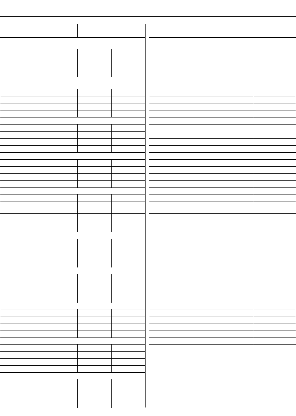
System Data
37
Table 15 Liebert Challenger ITR chilled water data, 50 Hz
Capacity Data kW (BTU/H) @ 7.2°C (45°F ) EWT, 5.6°C (10°F) Water Rise; Net Capacity Data
Indoor Unit
BR = Horizontal Flow BR 101C Indoor Unit BR 101C
37.8ºC DB, 21.1ºC WB (100ºF DB, 70ºF WB) 20% RH, 6.7°C (12°F)
Water Rise Fan Data (Blower A12x9AT)**
Total kW (BTU/H) 34.0 116,000 Standard Air, CMH (CFM) 4420 (2600)
Sensible kW (BTU/H) 31.9 109,000 Standard Fan Motor, kW (hp) 1.1 (1-1/2)
Flow Rate l/s (GPM) 1.3 19.9 Opt Fan Motor, kW (hp) 1.5 (2)
Pressure Drop kPa (ft) 66.5 22.3 Ext Static, Pa (in. WG) 75 (.3)
35ºC DB, 20.2ºC WB (95ºF DB, 68.3ºF WB) 24% RH,
6.1°C (11°F) Water Rise Chilled Water Coil (V-Frame, at standard conditions)
Total kW (BTU/H) 31.1 106,000 Face Area, m2 (ft2) .62 (6.67)
Sensible kW (BTU/H) 29.0 99,100 Rows 4
Flow Rate l/s (GPM) 1.3 19.9 Face Velocity, m/s (FPM) 1.9 (375)
Pressure Drop kPa (ft) 66.5 22.3 Electric Reheat 2-Stage (Stainless Steel, Fin Tubular) - Std
32.2ºC DB, 19.2ºC WB (90ºF DB, 66.5ºF WB) 28% RH Capacity, element kW (inc. motor heat, BTU/H) 15 (56,200)
Total kW (BTU/H) 28.2 96,100 Hot Water Reheat 82.2°C (180°F) EWT, 23.9°C (75°F) EAT -
Optional (Includes std air volume and opt. fan motor hp)
Sensible kW (BTU/H) 26.0 88,900
Flow Rate l/s (GPM) 1.3 20.0 Capacity, inc. motor heat, kW (BTU/H) 25.3 (86,200)
Pressure Drop kPa (ft) 66.8 22.4 Flow Rate, l/s (GPM) .32 (5.0)
29.4ºC DB, 18ºC WB (85ºF DB, 64.4ºF WB) 32% RH Pressure drop, kPa (ft.) 50.4 (16.9)
Total kW (BTU/H) 24.7 84,200 Infrared Humidifier - Standard
Sensible kW (BTU/H) 23.0 78,400 Capacity, kg/hr (lb/hr) 5 (11)
Flow Rate l/s (GPM) 1.1 17.6 kW 4.8
Pressure Drop kPa (ft) 52.7 17.7 Steam Generating Humidifier - Optional
26.7ºC DB, 17.1ºC WB (80ºF DB, 62.7ºF WB) 38% RH Capacity, kg/hr (lb/hr) 5 (11)
Total kW (BTU/H) 21.5 73,500 kW 3.9
Sensible kW (BTU/H) 19.6 66,900 Filter Section - Efficiencies per ASHRAE 52.1 - Disposable
Type
Flow Rate l/s (GPM) 1.0 15.8 20% Eff. available in 51mm (2") - Standard, or Optional 102mm (4")
Depths; other Optional 102mm (4") Eff. are: 30%, 40-45%, 60-65%
Pressure Drop kPa (ft) 42.9 14.4 Nominal Size - mm 28.5 x 29.5
26.7ºC DB, 19.2ºC WB (80ºF DB, 66.5ºF WB) 50% RH Nominal Size - inches 724 x 749
Total kW (BTU/H) 27.5 94,000 Effective Surface Area - m2 (ft2) 2.2 (24.1)
Sensible kW (BTU/H) 19.8 67,500 Connection Sizes-Challenger ITR Unit
Flow Rate l/s (GPM) 1.2 19.7 CW Supply 1 1/8 OD Cu
Pressure Drop kPa (ft) 65.9 22.1 CW Return 1 1/8 OD Cu
23.9ºC DB, 16.9ºC WB (75ºF DB, 62.5ºF WB) 50% RH Humidifier Supply 1/4 OD Cu
Total kW (BTU/H) 20.4 69,700 Condensate Drain 1/2 FPT
Sensible kW (BTU/H) 16.8 57,500 Control Valve
Flow Rate l/s (GPM) 0.9 14.7 Maximum design water pressure 1034.4 kPa (150 PSI)
Pressure Drop kPa (ft) 38.1 12.8 Valve Actuator Modulating
23.9ºC DB, 16.2ºC WB (75ºF DB, 61.1ºF WB) 45% RH Sensors Proportional
Total kW (BTU/H) 19.0 64,800 Valve Body Three-Way
Sensible kW (BTU/H) 17.4 59,500 Valve Size, in. 1
Flow Rate l/s (GPM) 0.8 13.3 Cv 13.9
Pressure Drop kPa (ft) 31.6 10.6 Two-Way Valve (Optional)
22.2ºC DB, 15.6ºC WB (72ºF DB, 60.1ºF WB) 50% RH Close Off Pressure - kPa (PSI) 483 (70)
Total kW (BTU/H) 16.7 57,100
* The net capacity data has fan motor heat factored in for all ratings
and the entering air condition of 72°F (22.2°C) and 50% RH is the
standard rating for ASHRAE 127-2001.All capacities are nominal
values; actual performance will be ±5%.
** Data rated with 2" 20% ASHRAE filter. Some options or
combinations of options may result in reduced airflow. Consult
factory for recommendations.
Sensible kW (BTU/H) 15.1 51,400
Flow Rate l/s (GPM) 0.8 12.0
Pressure Drop kPa (ft) 26.2 8.8
22.2ºC DB, 14.8ºC WB (72ºF DB, 58.7ºF WB) 45% RH
Total kW (BTU/H) 15.7 53,500
Sensible kW (BTU/H) 15.4 52,400
Flow Rate l/s (GPM) 0.7 11.1
Pressure Drop kPa (ft) 22.6 7.6
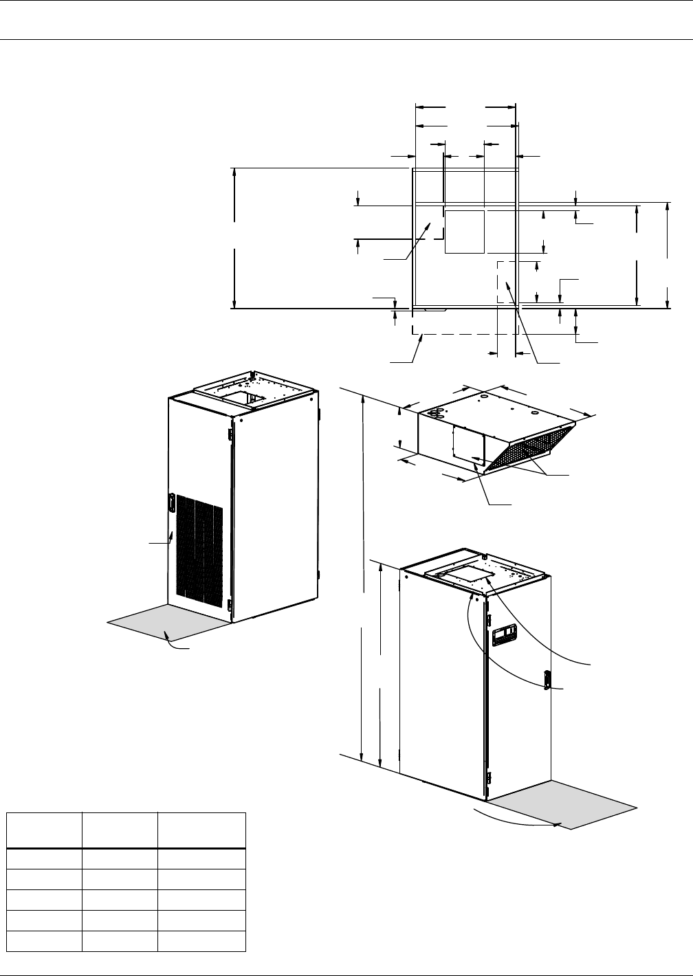
Dimensional Drawings
38
14.0 DIMENSIONAL DRAWINGS
Figure 11 Cabinet and floor planning dimensional data—Horizontal flow models
DPN001523
Pg. 2, Rev. 1
Filter Access
by Opening Door
UNIT
TOP VIEW
32-1/2"
(826mm)
5/8"
(16mm)
9-5/8"
(244mm)
8-1/2"
(216mm)
31-1/2"
(800mm)
1-7/8"
(48mm)
12-1/2"
(318mm)
30-1/2"
(775mm)
30-1/2"
(775mm)
32-1/2"
(826mm)
32-1/2"
(826mm)
1-5/8"
(41mm)
13"
(330mm)
Projection of
Display Bezel
Standard Piping Location
45-1/8"
(1147mm)
5-1/2"
(140mm)
15-1/16"
(382mm)
76"
(1930mm)
91-1/16"
(2313mm)
Blower Outlet with
1" (25.4mm) Flange
Shaded area indicates
a recommended
clearance of 34" (864mm)
for component access
Shaded area indicates a recommended
clearance of 34" (864mm) for component access
UNIT DIMENSIONAL DATA
FRONT VIEW
UNIT DIMENSIONAL DATA
REAR VIEW
10-1/4"
(260mm)
7/8" (22.2mm) Flange for
Duct or Plenum Connection
43-5/16"
(1100mm)
11-3 /4 "
(298mm)
Remove Blocker Panel
for Air Discharge Left
and/or Right Side Panels
Standard Electrical Outlet
Location Through Unit
12-5/8"
(321mm)
Discharge Air Opening
Plenum Overhang
UNIT TOP VIEW
50 Hz
Models
60 Hz
Models
Unit Weight
lb. (kg)
BR059E BR060E 649 (294)
BR065A BR067A 744 (337)
BR070WG BR071WG 814 (369)
BR101C BR102C 659 (299)
BM058G BM061G 854 (387)
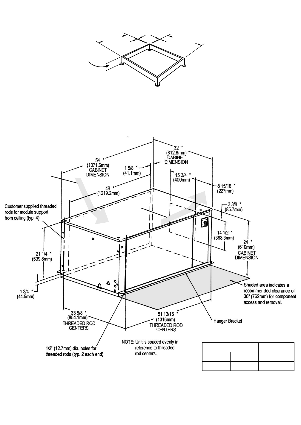
Dimensional Drawings
39
Figure 12 Cabinet and floor planning dimensional data
Figure 13 Cabinet and floor planning dimensional data—Split system—5-ton centrifugal fan condensing
unit
See Specification
Sheet for floor stand
height ordered
OPTIONAL FLOOR STAND
DIMENSIONAL DATA
1"
(25mm)
30-1/2"
(775mm)
30-1/2"
(775mm)
SL-11897
Pg. 7
Air Intake
Air
Exhaust
Model Net Weight
lbs (kg)60 Hz 50 Hz
MC_65A MC_64A 449 (204)
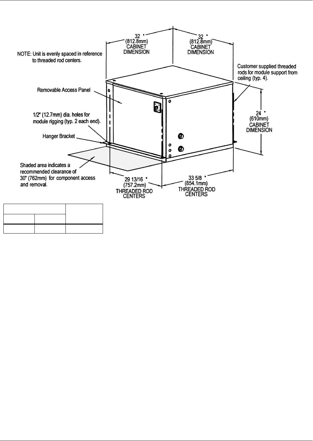
Dimensional Drawings
40
Figure 14 Cabinet and floor planning dimensional data—Split system—5-ton water/glycol-cooled
condensing unit
Model Net Weight
lbs (kg)60 Hz 50 Hz
MC_69W MC_68W 282 (128)
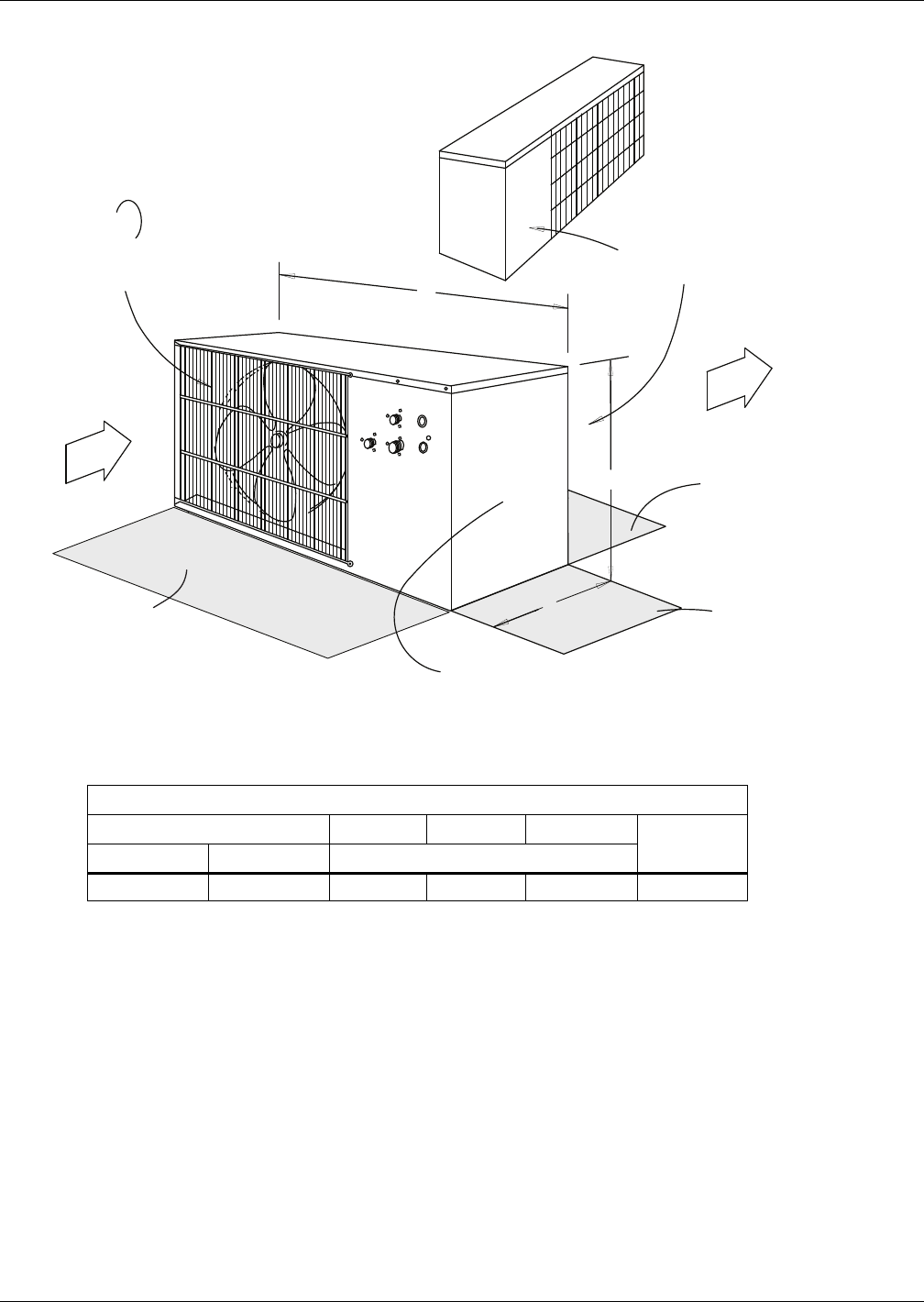
Dimensional Drawings
41
Figure 15 Cabinet and floor planning dimensional data—Split System—Propeller fan condensing unit
A
B
C
Fan Rotation
CCW
(left side)
SL-11081
Pg 4
Left Air
Intake
Shaded area indicates
a minimum clearance of
18" (457mm) for proper air flow Removable (front) panel for
access to high voltage and low voltage
connections and to refrigeration components
Shaded area indicates
a recommended clearance of
24" (610mm) for for component
access and removal
Shaded area indicates
a minimum clearance of
18" (457mm) for proper air flow
Right Air
Discharge
Removable (Right ) panel
for access to refrigeration component
C
C
C
C
C
Outdoor Propeller Fan Condensing Unit
Model Width (A) Depth (C) Height (B) Net Weight
lbs (kg)60 Hz 50 Hz Dimensions - Inches (mm)
PFH067A-_L PFH066A-_L 53 (1343) 18 (457) 36-1/4 (918) 351 (159)
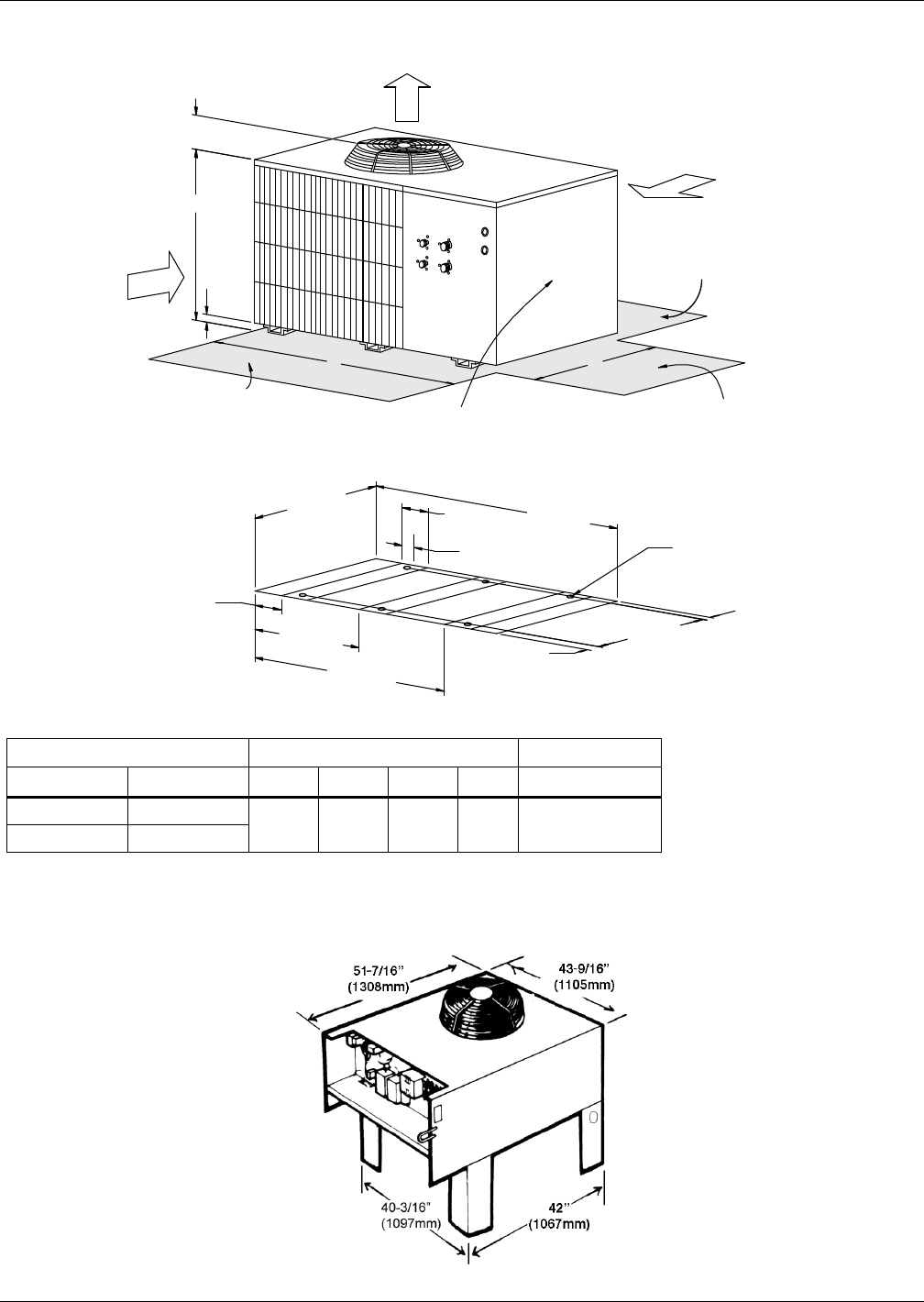
Dimensional Drawings
42
Figure 16 Cabinet and floor planning dimensional data—Propeller fan condensing modules—Vertical air
discharge
Figure 17 Cabinet and floor planning dimensional data—Self-contained system—Air-cooled condenser or
drycooler
Shaded area indicates
a recommended clearance
of 24" (610mm) for component
access.
Shaded area indicates
a recommended clearance
of 18" (457mm) for proper
air flow.
Shaded area indicates
a recommended clearance
of 18" (457mm) for proper
air flow.
Top A i r
Discharge Right
Air
Intake
Removable front panel for
access to high voltage and
low voltage connections,
and refrigeration components.
Left Air
Intake
Guard
Height
DPN000131
Rev. 0
D
B
Footprint Dimensions
36-1/8"
(918mm)
4-23/32"
(120mm) 25-3/32 "
(637mm)
46-7/32 "
(1174mm)
4" Typ.
(102mm) 53-3/16"
(1351mm) 1/2" Bolt-Down
Holes (6 places)
32-1/8"
(816mm)
2" Typ.
(51mm)
2"
(51mm)
2"
(51mm)
2"
(51mm)
AC
Model Numbers Dimensional Data in. (mm) Module Weight
60 HZ 50 HZ A B C D lbs (kg) net.
PFH067A-_H PFH066A-_H 53
(1343)
36-1/4
(918)
38-1/2
(978)
5-1/2
(140)
488
(222)
PFHZ67A-_H PFHZ66A-_L
Liebert Lee-Temp Receiver
L = 40" (1016mm)
W = 7-1/2" (190mm)

Electrical Data
43
15.0 ELECTRICAL DATA
Table 16 Liebert Challenger ITR electrical data1—60 Hz
Model Type
Self-Contained Split System Evaporator or Chilled Water
BR067A, BR071WG, BM061G BR060E, BR102C
Voltage
All Voltages Are 3 Phase Unless Noted Otherwise
208 230 460 575 208 230 460 575
With Electric Reheat and Humidifier (Infrared or Steam Generating) (Note: See Table 17 for units w/SCR reheats.2)
Motor 1.5 hp (1.1 kW) 1.5 hp (1.1 kW)
FLA 68.0 65.0 32.3 24.6 60.6 55.4 28.1 24.6
WSA 83.6 80.0 39.7 30.8 75.8 69.3 35.1 30.8
OPD90904030 80 70 40 35
Motor 2.0 hp (1.5 kW) 2.0 hp (1.5 kW)
FLA 69.8 66.6 33.1 25.2 62.4 57.0 28.9 25.2
WSA 85.4 81.6 40.5 31.5 78.0 71.3 36.1 31.5
OPD90904530 80 80 40 35
Motor 3.0 hp (2.2 kW) 3.0 hp (2.2 kW)
FLA 72.9 69.4 34.5 26.4 65.5 59.8 30.3 26.4
WSA 88.5 84.4 41.9 33.0 81.9 74.8 37.9 33.0
OPD90904535 90 80 40 35
Humidifier Only (Infrared or Steam Generating)
Motor 1.5 hp (1.1 kW) 1.5 hp (1.1 kW)
FLA 39.7 37.0 18.4 16.9 19.0 16.3 8.4 9.5
WSA 44.9 42.2 20.9 18.8 23.8 20.4 10.5 11.9
OPD60603025 25 20 15 15
Motor 2.0 hp (1.5 kW) 2.0 hp (1.5 kW)
FLA 41.5 38.6 19.2 17.5 20.8 17.9 9.2 10.1
WSA 46.7 43.8 21.7 19.4 26.0 22.4 11.5 12.6
OPD60603025 30 25 15 15
Motor 3.0 hp (2.2 kW) 3.0 hp (2.2 kW)
FLA 44.6 41.4 20.6 18.7 23.9 20.7 10.6 11.3
WSA 49.8 46.6 23.1 20.6 29.9 25.9 13.3 14.1
OPD70603025 35 30 15 15
Electric Reheat Only (Note: See Table 17 for Self-contained units w/SCR reheats.2)
Motor 1.5 hp (1.1 kW) 1.5 hp (1.1 kW)
FLA 68.0 65.0 32.3 24.6 47.3 44.3 22.3 17.2
WSA 83.6 80.0 39.7 30.2 59.1 55.4 27.9 21.5
OPD90904030 60 60 30 25
Motor 2.0 hp (1.5 kW) 2.0 hp (1.5 kW)
FLA 69.8 66.6 33.1 25.2 49.1 45.9 23.1 17.8
WSA 85.4 81.6 40.5 30.8 61.4 57.4 28.9 22.3
OPD90904530 70 60 30 25
Motor 3.0 hp (2.2 kW) 3.0 hp (2.2 kW)
FLA 72.9 69.4 34.5 26.4 52.2 48.7 24.5 19.0
WSA 88.5 84.4 41.9 32.0 65.3 60.9 30.6 23.8
OPD90904535 60 70 35 20
Without Electric Reheat and Humidifier
Motor 1.5 hp (1.1 kW) 1.5 hp (1.1 kW)
FLA 26.4 25.9 12.6 9.5 5.7 5.2 2.6 2.1
WSA 31.6 31.1 15.1 11.4 7.1 6.5 3.3 2.6
OPD50502515 15 15 15 15
Motor 2.0 hp (1.5 kW) 2.0 hp (1.5 kW)
FLA 28.2 27.5 13.4 10.1 7.5 6.8 3.4 2.7
WSA 33.4 32.7 15.9 12.0 9.4 8.5 4.3 3.4
OPD50502515 15 15 15 15
Motor 3.0 hp (2.2 kW) 3.0 hp (2.2 kW)
FLA 31.3 30.3 14.8 11.3 10.6 9.6 4.8 3.9
WSA 36.5 35.5 17.3 13.2 13.3 12.0 6.0 4.9
OPD50502520 20 20 15 15
1. Contact factory for 380-3-60 data.
2. For Split System Evaporators with SCR reheat, use the values above.
The values above were calculated per UL Standard 1995.
FLA = Full Load Amps (Input Amps); WSA = Wire Size Amps (Minimum Supply Circuit Ampacity); OPD = Maximum Overcurrent Protective Device Size
RLA = Rated Load Amps; LRA = Locked Rotor Amps
* R = In the Row; M = In the Row with Econ-O-Coil
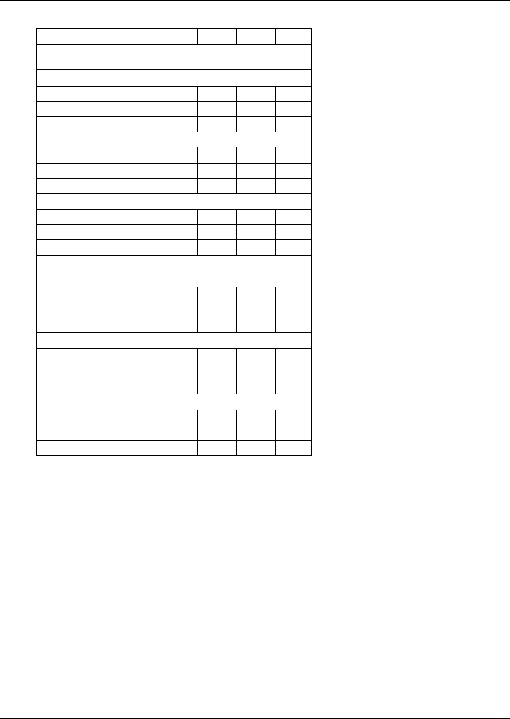
Electrical Data
44
Table 17 Self-contained with SCR reheat *
Voltage (3, 60 Hz) 208 230 460 575
Electric Reheat and Humidifier (Infrared or Steam
Generating)
Motor 1.5 hp (1.1 kW)
FLA 81.3 76.1 38.1 N/A
WSA 96.9 91.1 45.5 N/A
OPD 100 100 50 N/A
Motor 2.0 hp (1.5 kW)
FLA 83.1 77.7 38.9 N/A
WSA 98.7 92.7 46.3 N/A
OPD 100 100 50 N/A
Motor 3.0 hp (2.2 kW)
FLA 86.2 80.5 40.3 N/A
WSA 101.8 95.5 47.7 N/A
OPD 110 100 50 N/A
Electric Reheat Only
Motor 1.5 hp (1.1 kW)
FLA 68.0 65.0 32.3 N/A
WSA 83.6 80.0 39.7 N/A
OPD 90 90 40 N/A
Motor 2.0 hp (1.5 kW)
FLA 69.8 66.6 33.1 N/A
WSA 85.4 81.6 40.5 N/A
OPD 90 90 45 N/A
Motor 3.0 hp (2.2 kW)
FLA 72.9 69.4 34.5 N/A
WSA 88.5 84.4 41.9 N/A
OPD 90 90 45 N/A
Note: Compressor is locked on. Heater is same size as standard.
* Contact factory for 380-3-60 data.
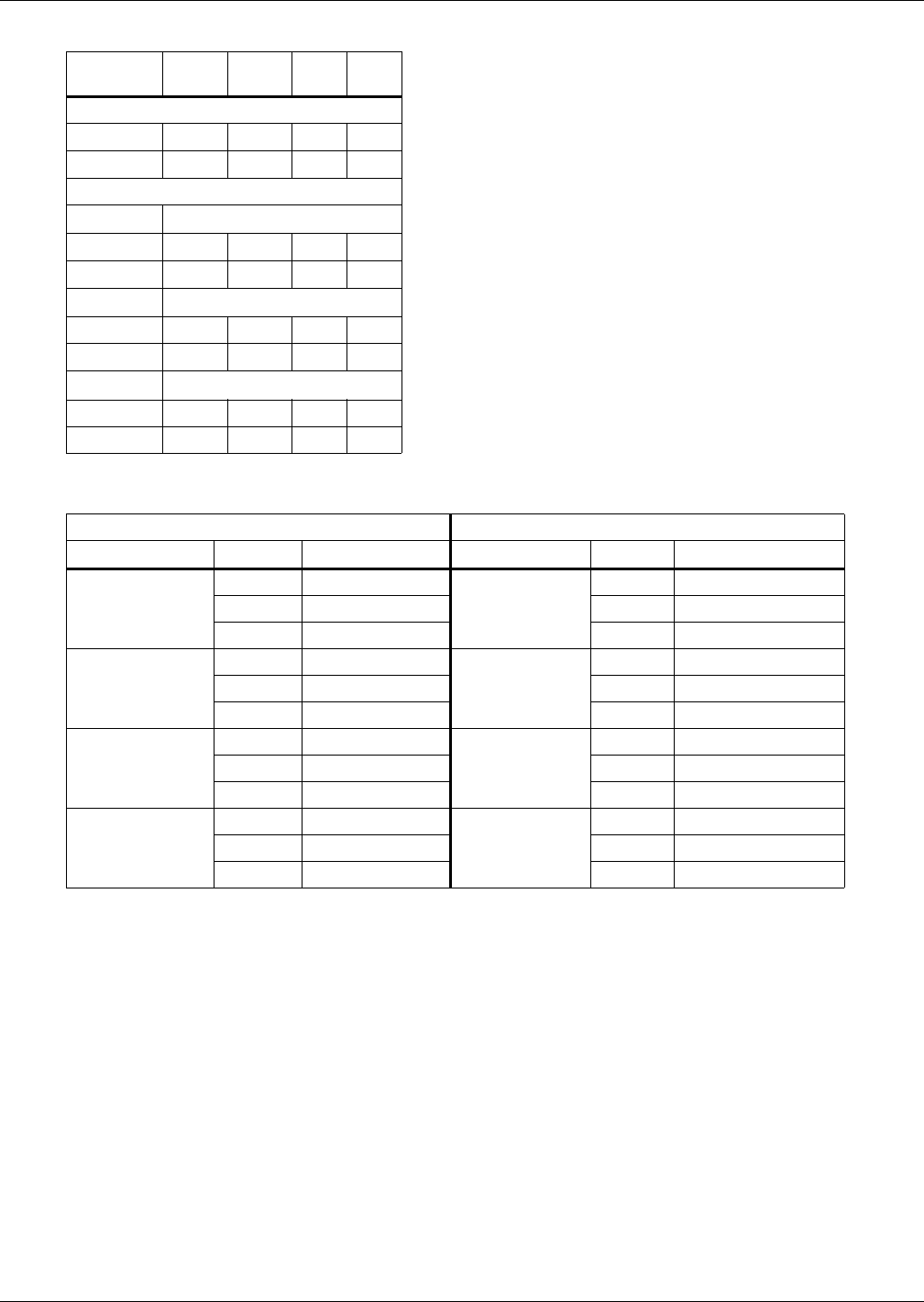
Electrical Data
45
Table 18 Scroll compressor and main fan (for comparison purposes only) *
Voltage
(3, 60 Hz) 208 230 460 575
Scroll Compressor
RLA 20.7 20.7 10.0 7.4
LRA 128.0 128.0 63.0 49.0
Main Fan
Motor 1.5 hp (1.1 kW)
RLA 5.7 5.2 2.6 2.1
LRA 35.9 31.2 15.6 12.6
Motor 2.0 hp (1.5 kW)
RLA 7.5 6.8 3.4 2.7
LRA 46.9 40.8 20.4 16.2
Motor 3.0 hp (2.2 kW)
RLA 10.6 9.6 4.8 3.9
LRA 66.0 58.0 26.8 23.4
* Contact factory for 380-3-60 data.
Table 19 Outdoor condensing units
Electrical Data 60 Hz 95°F (35°C) Ambient Electrical Data 60 Hz 105°F (40°C) Ambient
Voltage Model PFH067A-_L Voltage Model PFH067A-_H3
208/230-3-60
FLA 24.1
208/230-3-60
FLA 24.2
WSA 29.3 WSA 29.4
OPD 45.0 OPD 50.0
380-3-60
FLA 12.4
380-3-60
FLA 12.4
WSA 15.1 WSA 15.1
OPD 25.0 OPD 25.0
460-3-60
FLA 11.7
460-3-60
FLA 11.7
WSA 14.2 WSA 14.2
OPD 20.0 OPD 20.0
575-3-60
FLA 9.1
575-3-60
FLA 9.3
WSA 11.1 WSA 11.3
OPD 15.0 OPD 15.0
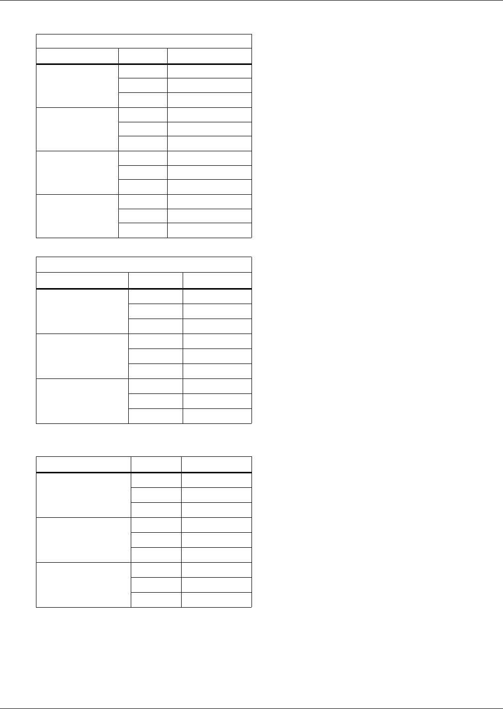
Electrical Data
46
Table 20 Outdoor condensing units—Quiet-Line
Electrical Data 60 Hz, Quiet-Line, 95°F (35°C)
Voltage Model PFHZ67A-_L
208/230-3-60
FLA 21.1
WSA 25.9
OPD 45.0
380-3-60
FLA 12.5
WSA 15.2
OPD 25.0
460-3-60
FLA 10.9
WSA 13.4
OPD 20.0
575-3-60
FLA 8.8
WSA 10.8
OPD 15.0
Table 21 Indoor condensing units, air-cooled *
Electrical Data 60 Hz 95°F (35°C) Ambient
Voltage Model MC_65A
208/230-3-60 FLA 26.5
WSA 31.7
OPD 50.0
460-3-60 FLA 12.9
WSA 15.4
OPD 25.0
575-3-60 FLA 9.7
WSA 11.6
OPD 15.0
* Contact factory for 380-3-60 data.
Table 22 Indoor condensing units, water-cooled *
Voltage Model MC_69W
208/230-3-60 FLA 20.7
WSA 25.9
OPD 45.0
460-3-60 FLA 10.0
WSA 12.5
OPD 20.0
575-3-60 FLA 7.4
WSA 9.3
OPD 15.0
* Contact factory for 380-3-60 data.
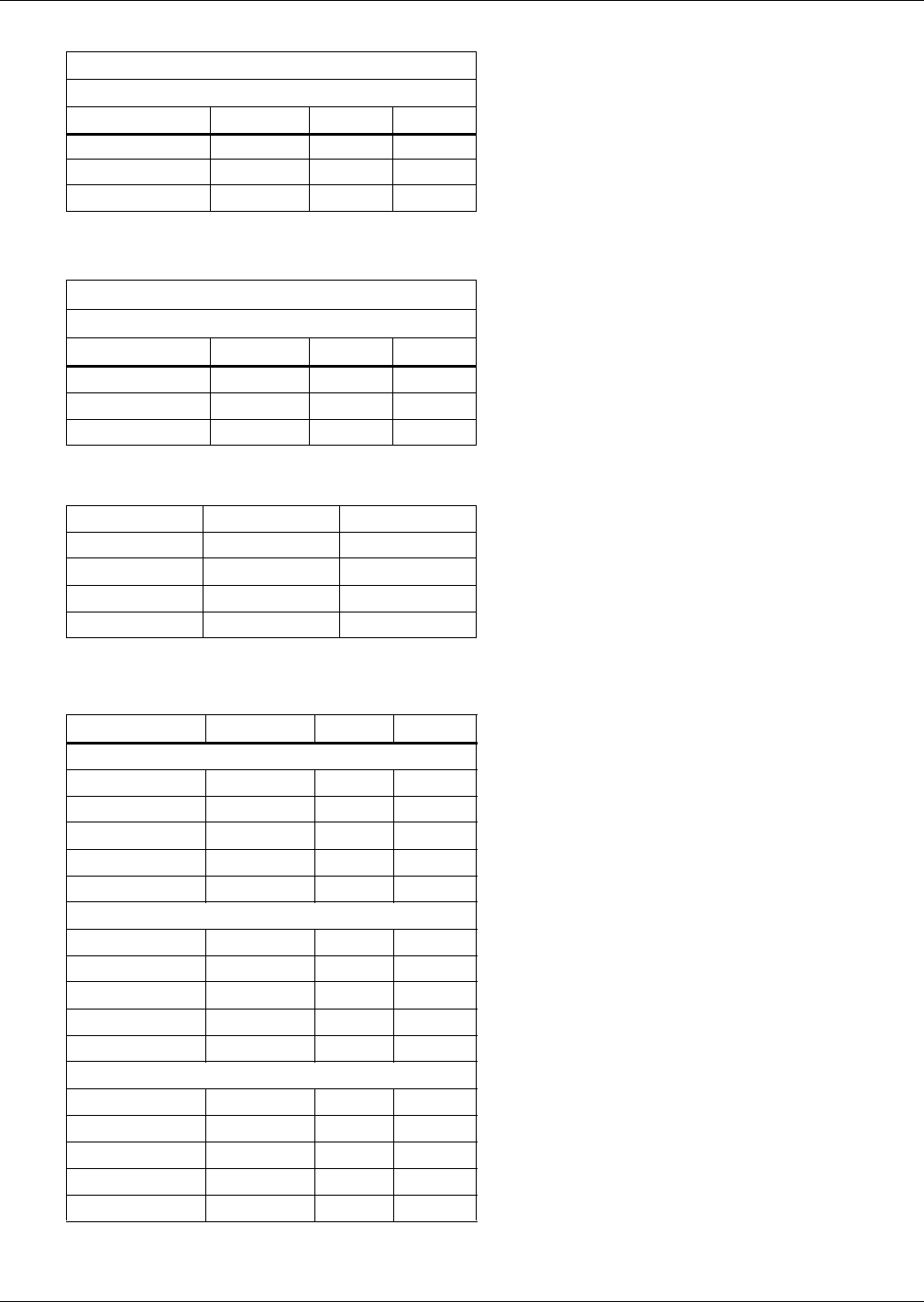
Electrical Data
47
Table 23 Fan speed control condensers *
95°F (35°C) Ambient, 1 Phase - 60 Hz
CSF104
Voltage 208/230 460 575
FLA 4.8 2.5 1.9
WSA 6.0 3.1 2.4
OPD 15.0 15.0 15.0
* Contact factory for 380-3-60 data.
Table 24 Liebert Lee-Temp condensers *
95°F (35°C) Ambient, 3 Phase - 60 Hz
CSL104
Voltage 208/230 460 575
FLA 3.5 1.7 1.4
WSA 4.4 2.1 1.8
OPD 15.0 15.0 15.0
* Contact factory for 380-3-60 data.
Table 25 Liebert Lee-Temp receiver heater pads for use w/CSL condensers
Volts 120 230
Watts/Pad 150 150
FLA 1.4 0.7
WSA 1.8 0.9
OPD 15 15
Separate electrical source required for continuous operation
of single phase heater pads for Liebert Lee-Temp.
Table 26 Drycooler and pump package - 95°F (35°C) ambient *
Voltage 208/230 460 575
Glycol
DSF Model 112 112 112
Pump Hp 3/4 3/4 3/4
FLA 7.0 3.3 2.7
WSA 7.9 3.7 3.1
OPD 15 15.0 15.0
Glycol DS0174
DSF Model 174 174 174
Pump Hp 1.5 1.5 1.5
FLA 13.6 6.4 5.2
WSA 15.3 7.2 5.8
OPD 20 15.0 15.0
GLYCOOL
DSO Model 112 112 112
Pump Hp 1-1/2 1-1/2 1-1/2
FLA 10.1 4.7 3.8
WSA 11.8 5.5 4.4
OPD 15 15 15
1. Pump and drycooler powered from same 3 phase feeder.
* Contact factory for 380-3-60 data.
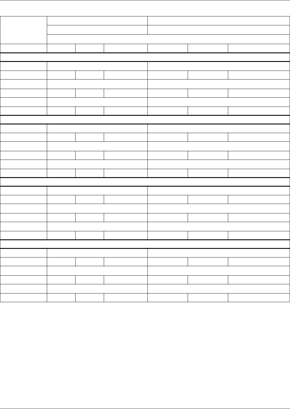
Electrical Data
48
Table 27 Liebert Challenger ITR electrical data—50 Hz
Model Type
Self-Contained Split System Evaporator or Chilled Water
B*065A, 070WG, 058G B*059E, 101C
3 Phase, 50Hz
Voltage 200 230 380/415 200 230 380/415
With Electric Reheat and Humidifier (Infrared or Steam Generating) (Note: See Table 28 for units w/SCR reheats.1)
Motor 1.1 kW (1.5 hp) 1.1 kW (1.5 hp)
FLA 66.0 64.4 34.4 58.1 54.8 30.8
Motor 1.5 kW (2.0 hp) 1.5 kW (2.0 hp)
FLA 67.7 65.9 35.2 59.8 56.3 31.6
Motor 2.2 kW (3.0 hp) 2.2 kW (3.0 hp)
FLA 70.8 68.6 36.8 62.9 59.0 33.2
Humidifier Only (Infrared or Steam Generating)
Motor 1.1 kW (1.5 hp) 1.1 kW (1.5 hp)
FLA 38.8 36.4 19.1 18.1 15.7 9.1
Motor 1.5 kW (2.0 hp) 1.5 kW (2.0 hp)
FLA 40.5 37.9 19.9 19.8 17.2 9.9
Motor 2.2 kW (3.0 hp) 2.2 kW (3.0 hp)
FLA 43.6 40.6 21.5 22.9 19.9 11.5
Electric Reheat Only (Note: See Table 28 for units w/SCR reheats.1)
Motor 1.1 kW (1.5 hp) 1.1 kW (1.5 hp)
FLA 66.0 64.4 34.4 45.3 43.7 24.4
Motor 1.5 kW (2.0 hp) 1.5 kW (2.0 hp)
FLA 67.7 65.9 35.2 47.0 45.2 25.2
Motor 2.2 kW (3.0 hp) 2.2 kW (3.0 hp)
FLA 70.8 68.6 36.8 50.1 47.9 26.8
Without Electric Reheat and Humidifier
Motor 1.1 kW (1.5 hp) 1.1 kW (1.5 hp)
FLA 26.0 25.3 12.7 5.3 4.6 2.7
Motor 1.5 kW (2.0 hp) 1.5 kW (2.0 hp)
FLA 27.7 26.8 13.5 7.0 6.1 3.5
Motor 2.2 kW (3.0 hp) 2.2 kW (3.0 hp)
FLA 30.8 29.5 15.1 10.1 8.8 5.1
1. For Split System Evaporators with SCR reheat, use the values above.
FLA = Full Load Amps (Input Amps)
RLA = Rated Load Amps
LRA = Locked Rotor Amps
* R = In The Row; M = In The Row with Econ-O-Coil
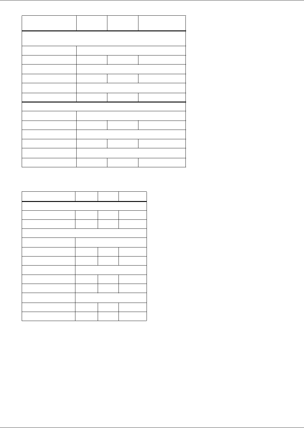
Electrical Data
49
Table 28 Self-contained with SCR reheat
Voltage
(3, 50 Hz) 200 230 380/415
Electric Reheat and Humidifier (Infrared or Steam
Generating)
Motor 1.1 kW (1.5 hp)
FLA 78.8 75.5 40.8
Motor 1.5 kW (2.0 hp)
FLA 80.5 77.0 41.6
Motor 2.2 kW (3.0 hp)
FLA 83.6 79.7 43.2
Electric Reheat Only
Motor 1.1 kW (1.5 hp)
FLA 66.0 64.4 34.4
Motor 1.5 kW (2.0 hp)
FLA 67.7 65.9 35.2
Motor 2.2 kW (3.0 hp)
FLA 70.8 68.6 36.8
Note: Compressor is locked on. Heater is same size as standard.
Table 29 Scroll compressor and main fan (for comparison only)
Voltage (3, 50 Hz) 200 230 380/415
Scroll Compressor
RLA 20.7 20.7 10.0
LRA 156.0 172.0 74.0
Main Fan
Motor 1.1 kW (1.5 hp)
RLA 5.3 4.6 2.7
LRA 35.8 31.2 17.9
Motor 1.5 kW (2.0 hp)
RLA 7.0 6.1 3.5
LRA 50.6 44.0 25.3
Motor 2.2 kW (3.0 hp)
RLA 10.1 8.8 5.1
LRA 58.5 51.0 29.3
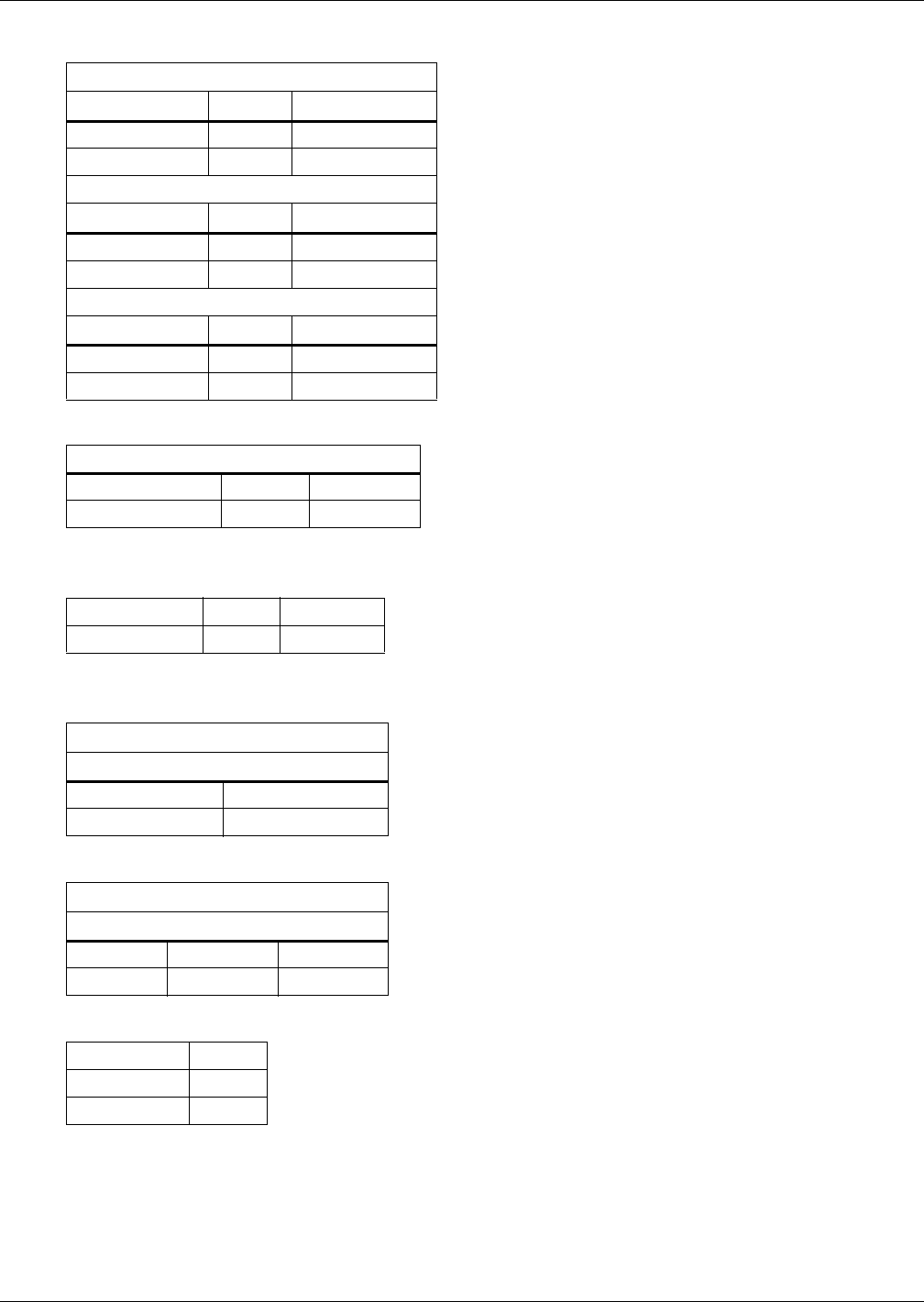
Electrical Data
50
Table 30 Outdoor condensing units
Electrical Data 50 Hz 35°C (95°F) Ambient
Voltage Model PFH066A-_L
200/230-3-50 FLA 24.1
380/415-3-50 FLA 13.2
Electrical Data 50 Hz 40°C (105°F) Ambient
Voltage Model PFH066A-_H
200/230-3-50 FLA 24.2
380/415-3-50 FLA 13.2
Electrical Data 50 Hz Quiet-Line 35°C (95°F)
Voltage Model PFHZ66A-_L
200/230-3-50 FLA 22.5
380/415-3-50 FLA 12.4
Table 31 Indoor condensing units air-cooled
Electrical Data 50 Hz 35°C (95°F) Ambient
Voltage Model MC_64A
380/415-3-50 FLA 13.7
1. Consult factory for 200/230 volts.
Table 32 Indoor condensing units water-cooled
Voltage Model MC_68W
380/415-3-50 FLA 10.0
1. Consult factory for 200/230 volts.
Table 33 Fan speed control condensers
35°C (95°F) Ambient (1 Phase - 50 Hz)
CSF104
Voltage 200/230
FLA 4.0
Table 34 Liebert Lee-Temp condensers
35°C (95°F) Ambient (3 Phase - 50 Hz)
CSL104
Voltage 200/230 380/ 415
FLA 3.5 1.7
Table 35 Liebert Lee-Temp receiver heater pads; for use w/CSL condensers
Volts 230
Watts/Pad 150
FLA 0.7
Separate electrical source required for continuous operation of
single phase heater pads for Liebert Lee-Temp.
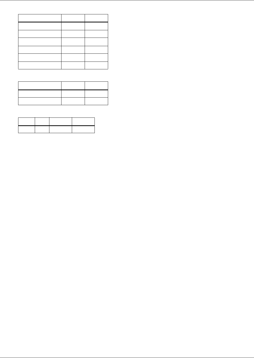
Electrical Data
51
Table 36 Drycooler only - 35°C (95°F) ambient, three-phase
Voltage (3, 50Hz) 200/230 380/415
DSF Model 112 112
FLA 3.5 1.7
DSO Model 112 112
FLA 3.5 1.7
DSO Model 174 174
FLA 7.0 3.4
Table 37 Drycooler only - 35°C (95°F) ambient, single phase
Voltage (1, 50Hz) 200/230 380/415
DSF Model 112 —
FLA 4.0 —
Table 38 Pumps
hp 200/230 380/415
1-1/2 FLA 5.4 3.0

Electrical Data
52
GUIDE SPECIFICATIONS—NOMINAL 23 OR 33KW ENVIRONMENTAL CONTROL SYSTEM
1.0 GENERAL
1.1 Summary
These specifications describe requirements for an environmental control system. The system shall be
designed to maintain temperature and relative humidity conditions within the room. The manufac-
turer shall design and furnish all equipment to be fully compatible with heat dissipation require-
ments of the site.
1.2 Design Requirements
The environmental control system shall be a Liebert Challenger ITR factory-assembled unit. Stan-
dard 60 Hz units shall be CSA (NRTL-C) certified. It shall be specifically designed for service from the
front and rear of the unit. The system shall be designed for draw-through air arrangement to insure
even air distribution to the entire face area of the coil.
Each system shall be capable of handling ____ CFM (CMH) at ____inches (mm) of water external
static pressure with a horizontal airflow pattern. It shall have a total cooling capacity of ____ BTU/HR
(kW), sensible cooling capacity of ____ BTU/HR (kW), based on the entering air condition of °F (°C)
dry bulb, and ____ °F (°C) wet bulb. These units are to be supplied with ____ Volt, ____ phase, ____ Hz
power supply. The humidifier shall have a capacity of ____ lbs/hr (kg/h). Reheat shall have a capacity
of _____ BTU/HR (kW). The main fan shall be ____ hp (kW).
1.3 Submittals
Submittals shall be provided with the proposal and shall include: Single-Line Diagrams; Dimen-
sional, Electrical, and Capacity data; Piping and Electrical Connection Drawings.
2.0 PRODUCT
2.1 All Systems
2.1.1 Cabinet and Frame Construction
The frame shall be constructed of MIG welded tubular and formed steel. All frame components shall
be finished in a black, powder-coat finish to protect against corrosion. The exterior panels shall be
20 gauge steel and shall be powder coated with ____ color paint. The panels shall be insulated with a
minimum 1 in. (25.4mm), 1-1/2 lbs. (0.68 kg) density fiber insulation. Front and side panels shall have
captive, 1/4 turn fasteners.
The cabinet shall be designed so that all components are serviceable and removable from the front
and rear of the unit.
2.1.2 Fan and Motor Section
The fan shall be the centrifugal type, double width, double inlet. The shaft shall be heavy duty steel
with self-aligning ball bearings with minimum life span of 100,000 hours.
The fan motor shall be 1750 RPM and mounted on an adjustable base. The drive package shall be
sized for 200% of the fan motor horsepower, and equipped with an adjustable motor pulley. The
fan/motor assembly shall be mounted on (vibration isolators) (solid base). The fan shall be located to
draw air over the coil to ensure even air distribution and maximum coil performance.
High Efficiency Motor (Optional)
The fan motor shall be a ____ hp (kW) high efficiency motor with a full load efficiency of ____ %.
2.1.3 Filter
The filter shall be____ inches (mm) thick and rated not less than _____ % (20%, 30%, 40-45%, 60-65%)
efficiency based on ASHRAE 52.1.
Prefilter (Optional)
The prefilter shall be 2 in. (50.8mm) thick with an efficiency of 20% based on ASHRAE 52.1.

Electrical Data
53
2.1.4 Advanced Microprocessor Control (Standard)
The Advanced control processor shall be microprocessor based with a front monitor LCD display
panel and control keys for user inputs. The controls shall be menu driven with on-screen prompts for
easy user operation. The system shall allow user review and programming of temperature and humid-
ity setpoints, alarm parameters, and setup selections including choice of control type. A password
shall be required to make system changes. For all user selections, the range of acceptable input (tem-
perature, humidity, or time delay) shall be displayed on the monitor screen. The system shall provide
monitoring of room conditions, operational status in % of each function, component run times, date
and time, and four analog inputs from sensors provided by others.
Control
The control system shall allow programming of the following room conditions:
• Temperature Setpoint 65 to 85°F (18-29°C)
• Temperature Sensitivity +1 to +9.9°F (0.6 to 5.6°C) in 0.1° increments
• Humidity Setpoint 20 to 80% RH
• Humidity Sensitivity +1 to +30% RH
All setpoints shall be adjustable from the individual unit front monitor panel. The microprocessor can
be set within these ranges, however, the unit may not be able to control to extreme combinations of
temperature and humidity.
Temperature and Humidity Sensors shall be capable of being calibrated using the front monitor panel
controls to coordinate with other temperature and humidity sensors in the room.
Predictive Humidity Control
The microprocessor shall calculate the moisture content in the room and prevent unnecessary humid-
ification and dehumidification cycles by responding to changes in dew point temperature.
Compressor Short-Cycle Control
The control system shall include a program to prevent compressor short-cycling.
System Auto-Restart
For start-up after power failure, the system shall provide automatic restart with a programmable (up
to 9.9 minutes in 6-second increments) time delay. Programming can be performed either at the unit
or from the central site monitoring system.
Sequential Load Activation
During start-up, or after power failure, the microprocessor shall sequence operational load activation
to minimize inrush current. Systems allowing multiple loads to start simultaneously are unaccept-
able.
Chilled Water/Hot Water/Econ-O-Coil Flush Cycles
Chilled water, hot water, and Econ-O-Cool coils (if unit is so equipped) shall be automatically flushed
to prevent the buildup of contaminants. Systems without this feature shall include the necessary
devices to bypass fluid into the coil on a programmed basis.
Front Monitor Display Panel
The microprocessor shall provide a front monitor LCD backlit display panel with 4 rows of 20 charac-
ters with adjustable contrast. This display (along with five front mounted control keys) shall be the
only operator interface required to obtain all available system information such as room conditions,
operational status, alarms, control and alarm setpoints, and all user selections including alarm
delays, sensor calibration, DIP switch selections, and diagnostics. All indicators shall be in language
form. No symbols or codes shall be acceptable.

Electrical Data
54
Alarms
The microprocessor shall activate an audible and visual alarm in event of any of the following condi-
tions:
• High Temperature
• Low Temperature
• High Humidity
• Low Humidity
• Short Cycle
• Compressor Overload (Optional)
• Main Fan Overload (Optional)
• Humidifier Problem
• High Head Pressure
• Change Filter
• Loss of Air Flow
• Low Suction Pressure
• Loss of Power
• Custom Alarm (#1 to #4)
Custom alarms are four customer accessible alarm inputs to be indicated on the front panel. Custom
alarms can be identified with prepared (programmed) alarm labels for the following frequently used
inputs:
• Water Under Floor
• Smoke Detected
• Standby GC Pump On
• Loss of Water Flow
•Standby Unit On
User customized text can be entered for two of the four custom alarms. Each alarm (unit and custom)
can be separately enabled or disabled, selected to activate the common alarm, and programmed for a
time delay of 0 to 255 seconds.
Audible Alarm
The audible alarm shall annunciate any alarm that is enabled by the operator.
Common Alarm
A programmable common alarm shall be provided to interface user selected alarms with a remote
alarm device.
Remote Monitoring
All alarms shall be communicated to the Liebert monitoring system with the following information:
date and time of occurrence, unit number, and present temperature and humidity.
Analog Inputs
The system shall include four customer accessible analog inputs for sensors provided by others. The
analog inputs shall accept a 4 to 20 mA signal. The user shall be able to change the input to 0 to 5
VDC or 0 to 10 VDC if desired. The gains for each analog input shall be programmable from the front
panel. The analog inputs shall be able to be monitored from the front panel.
Diagnostics
The control system and electronic circuitry shall be provided with self-diagnostics to aid in trouble-
shooting. The microcontroller board shall be diagnosed and reported as pass/not pass. Control inputs
shall be indicated as on or off at the front monitor panel. Control outputs shall be able to be turned on
or off from the front monitor panel without using jumpers or a service terminal. Each control output
shall be indicated by an LED on a circuit board.
Data Collection

Electrical Data
55
The control system shall maintain accumulative operating hours of compressor, reheat, humidifier,
fan motor, and Econ-O-Coil. The ten most recent alarms shall also be retained.
Communications
The microprocessor shall be compatible with all Liebert remote monitoring and control devices.
2.1.5 Advanced Microprocessor Control with Graphics (Optional)
The optional Advanced control processor shall be microprocessor based with a front monitor dot
matrix display panel and control keys for user inputs. The controls shall be menu driven with on-
screen prompts for easy user operation. The system shall allow user review and programming of tem-
perature and humidity setpoints, alarm parameters, and setup selections including choice of control
type. A password shall be required to make system changes. For all user selections, the range of
acceptable input (temperature, humidity, or time delay) shall be displayed on the monitor screen. The
system shall provide monitoring of room conditions, operational status in % of each function, compo-
nent run times, date and time, and four analog inputs from sensors provided by others.
Control
The control system shall allow programming of the following room conditions:
• Temperature Setpoint 65 to 85°F (18-29°C)
• Temperature Sensitivity +1 to +9.9°F (0.6 to 5.6°C) in 0.1° increments
• Humidity Setpoint 20 to 80% RH
• Humidity Sensitivity +1 to +30% RH
All setpoints shall be adjustable from the individual unit front monitor panel.
Temperature and Humidity Sensors shall be capable of being calibrated using the front monitor panel
controls to coordinate with other temperature and humidity sensors in the room.
Predictive Humidity Control
The microprocessor shall calculate the moisture content in the room and prevent unnecessary humid-
ification and dehumidification cycles by responding to changes in dew point temperature.
Compressor Short-Cycle Control
The control system shall include a program to prevent compressor short-cycling.
System Auto-Restart
For start-up after power failure, the system shall provide automatic restart with a programmable (up
to 9.9 minutes in 6-second increments) time delay. Programming can be performed either at the unit
or from the central site monitoring system.
Sequential Load Activation
During start-up, or after power failure, the microprocessor shall sequence operational load activation
to minimize inrush current. Systems allowing multiple loads to start simultaneously are unaccept-
able.
Chilled Water/Hot Water/Econ-O-Coil Flush Cycles
Chilled water, hot water, and Econ-O-Cool coils shall be automatically flushed to prevent the buildup
of contaminants. Systems without this feature shall include the necessary devices to bypass fluid into
the coil on a programmed basis.
Front Monitor Display Panel
The microprocessor shall provide a front monitor 240 x 120 dot matrix display panel with adjustable
backlighting. This display (along with five front mounted control keys) shall be the only operator
interface required to obtain all available system information such as room conditions, operational sta-
tus, graphical data, alarms, control and alarm setpoints, and all user selections including alarm
delays, sensor calibration, DIP switch selections, and diagnostics. All indicators shall be in language
form. No symbols or codes shall be acceptable.

Electrical Data
56
Alarms
The microprocessor shall activate an audible and visual alarm in event of any of the following condi-
tions:
• High Temperature
• Low Temperature
• High Humidity
• Low Humidity
• Short Cycle
• Compressor Overload (Optional)
• Main Fan Overload (Optional)
• Humidifier Problem
• High Head Pressure
• Change Filter
• Loss of Air Flow
• Low Suction Pressure
• Loss of Power
• Custom Alarm (#1 to #4)
Custom alarms are four customer accessible alarm inputs to be indicated on the front panel. Custom
alarms can be identified with prepared (programmed) alarm labels for the following frequently used
inputs:
• Water Under Floor
• Smoke Detected
• Standby GC Pump On
• Loss of Water Flow
•Standby Unit On
User-customized text can be entered for all four custom alarms. Each alarm (unit and custom) can be
separately enabled or disabled, selected to activate the common alarm, and programmed for a time
delay of 0 to 255 seconds.
Audible Alarm
The audible alarm shall annunciate any alarm that is enabled by the operator.
Common Alarm
A programmable common alarm shall be provided to interface user selected alarms with a remote
alarm device.
Remote Monitoring
All alarms shall be communicated to the Liebert site monitoring system with the following informa-
tion: date and time of occurrence, unit number, and present temperature and humidity.
Analog Inputs
The system shall include four customer accessible analog inputs for sensors provided by others. The
analog inputs shall accept a 4 to 20 mA signal. The user shall be able to change the input to 0 to 5
VDC or 0 to 10 VDC if desired. The gains for each analog input shall be programmable from the front
panel. The analog inputs shall be able to be monitored from the front panel.
Diagnostics
The control system and electronic circuitry shall be provided with self-diagnostics to aid in trouble-
shooting. The microcontroller board shall be diagnosed and reported as pass/not pass. Control inputs
shall be indicated as on or off at the front monitor panel.
Control outputs shall be able to be turned on or off from the front monitor panel without using jump-
ers or a service terminal. Each control output shall be indicated by an LED on a circuit board.

Electrical Data
57
Data Collection
The control system shall maintain accumulative operating hours of compressor, reheat, humidifier,
fan motor, Econ-O-Coil, and heat rejection. The sixty most recent alarms shall also be retained.
Graphing
The control shall display the following graphical data:
• Temperature, humidity, analog inputs
• Component operating status by hour
• Operating status
Communications
The microprocessor shall be compatible with all Liebert remote monitoring and control devices.
2.1.6 Infrared Humidifier (Standard)
The humidifier shall be of the infrared type consisting of high intensity quartz lamps mounted above
and out of the water supply. The evaporator pan shall be stainless steel and arranged to be service-
able without disconnecting water supply lines, drain lines or electrical connections. The complete
humidifier section shall be pre-piped ready for final connection. The infrared humidification system
shall use bypass air to prevent over-humidification of the controlled space. The auto flush system
shall automatically flush deposits from the humidifier pan. The system shall be field adjustable to
change the cycle time to suit local water conditions. The humidifier shall have a capacity of _____
lbs/hr (kg/h).
2.1.7 Steam Generating Humidifier (Optional)
The environmental control system shall be equipped with a steam generating humidifier that is con-
trolled by the microprocessor control system. It shall be complete with disposable canister, all supply
and drain valves, steam distributor, and electronic controls. The need to change canister shall be
annunciated on the microprocessor control panel. The humidifier shall have a capacity of ____ lbs/hr
(kg/h).
2.1.8 Electric Reheat (Standard)
The low-watt density, 304/304, stainless steel, finned-tubular electric reheat coils shall be capable of
maintaining room dry bulb conditions when the system is calling for dehumidification. The reheat
section shall include UL recognized safety switches to protect the system from overheating. The
capacity of the reheat coils shall be ____ BTU/HR (kW), ____ kW, controlled in ____ stage(s).
2.1.9 Hot Water Reheat (Optional)
The hot water reheat coil shall have copper tubes and aluminum fins with a capacity of _____
BTU/HR (kW) when supplied with _____ °F (°C) entering water temperature at _____GPM (l/s) flow
rate. Maximum pressure drop shall be _____ PSI (kPa). The control system shall be factory pre-piped
with a 2-way motorized control valve and cleanable Y-strainer.
2.1.10 SCR Electric Reheat (Optional)
The SCR (Silicon Controlled Rectifier) controller shall proportionally control the stainless steel
reheats to maintain the selected room temperature. The rapid cycling made possible by the SCR con-
troller provides precise temperature control, and the more constant element temperature improves
heater life. The capacity of the reheat coils shall be _____ BTU/HR (kW).
2.1.11 Floor Stand (Optional)
The floor stand shall be constructed of a heliarc-welded tubular steel frame. The floor stand shall be
coated using an autodeposition process to protect against corrosion. The floor stand shall have adjust-
able legs with vibration isolation pads. The floor stand shall be: 9 in. (23cm), 12 in. (30cm), 15 in.
(38cm), 18 in. (46cm), 21 in. (53cm), 24 in. (61cm) high.

Electrical Data
58
2.1.12 Plenum
The unit shall be supplied with a (2 way) (3 way) (4 way) (low-profile, cold-aisle) air discharge ple-
num. The plenum shall be 18 in. (457mm) high or less, insulated and powder painted the same color
as the room unit.
2.1.13 Disconnect Switch, Locking Type
The manual disconnect switch shall be mounted in the high voltage section of the electrical panel. The
switch shall prevent access to the high voltage electrical components until switched to the “OFF” posi-
tion.
2.1.14 Remote Sensors (Required for Select Applications)
The unit shall be supplied with remote temperature and humidity sensors. The sensors shall be con-
nected to the unit by a 30 ft. (9m), 60 ft. (18m), 90 ft. (27m), 120 ft. (36m), 150 ft. (45m) shielded cable.
2.1.15 Remote Sensor Installation Location
The remote temperature and humidity sensor should be installed in the cold aisle in front of the
equipment to be cooled. It should be mounted at the farthest point from the cooling unit that supply
air needs to reach but still within the unit’s area of influence. The sensor should be installed at the
highest point that equipment will draw in cooled air.
2.1.16 Firestat (Optional)
The firestat shall immediately shut down the system when high temperatures are detected. The fir-
estat shall be mounted in the electrical panel with the sensing element in the return air.
2.1.17 Smoke Detector (Optional)
The smoke detector senses the return air, shuts down the unit upon detection, and sends visual and
audible alarm. Dry contacts are available for a remote customer alarm. This smoke detector is not
intended to function as or replace any room smoke detection system that may be required by local or
national codes.
2.1.18 Condensate Pump
The condensate pump shall have the capacity of ____ GPH (l/h) at ____ ft. (m) head @ ____ V - ____ Hz.
It shall be complete with (single) (dual) integral float switch, pump, motor assembly, and reservoir.
2.2 Direct Expansion Self-Contained Systems
Direct Expansion Coil
The evaporator coil shall have _____ sq.ft. (sq. m) face area, _____ rows deep. It shall be configured as
V-frame and be constructed of copper tubes and aluminum fins and have a maximum face velocity of
_____ ft. per minute (m/s) at _____ CFM (CMH). The coil shall be provided with a stainless steel drain
pan.
Refrigeration System
The refrigeration system shall consist of a high efficiency scroll compressor, hot gas bypass, pressure
safety switches, externally equalized expansion valve, filter drier, refrigerant sight glass and mois-
ture indicator.
2.2.1 Air-Cooled Self-Contained Systems
Pump Down Control
A liquid line solenoid valve shall be provided for pump down control.
Crankcase Heater
A crankcase heater shall be provided for additional system protection from refrigerant migration dur-
ing off cycles.
Propeller Fan Condenser (Standard)
The Liebert manufactured air-cooled condenser shall be the low profile, slow speed, direct-drive, pro-
peller-fan type. The condenser shall be constructed of aluminum and contain a copper tube, alumi-
num fin coil with an integral electric control panel. The system shall be designed for _____ °F (°C)
ambient. The air-cooled condenser shall have a _____ Volt, _____ phase, ____ Hz power supply.

Electrical Data
59
Fan Speed Control (FSC) Head Pressure Control (Standard)
The winter control system for the air-cooled condenser shall be Liebert Fan Speed Control (FSC). The
variable speed motor shall turn on at 10% of the supply voltage and modulate in response to head
pressure to a full speed of 1050 RPM. It shall be designed with ball bearings, permanent lubrication,
and internal overload protection.
The control system shall be complete with transducers, thermostats and electrical control circuit, fac-
tory prewired and tested in an integral control panel. The transducer shall automatically sense the
head pressure of the compressor and control the variable speed fan on the air-cooled condenser to
properly maintain the head pressure.
The fan speed control system shall provide positive start-up and operation in ambient temperature as
low as -20°F (-29°C). Included with the fan speed control system shall be a solid state winter start kit
as an integral feature of the electronic control panel.
Liebert Lee-Temp Head Pressure Control (Optional)
The winter control system for the air-cooled condenser shall be “Liebert Lee-Temp.” The Liebert Lee-
Temp system shall allow startup and positive head pressure control with ambient temperatures as
low as -30°F (-34.4°C). The Liebert Lee-Temp package shall include: insulated receiver, pressure
relief valve for each circuit, head pressure three-way control valve, and rotalock valve for isolating the
refrigerant charge. The Lee- Temp receiver shall be factory insulated and mounted ready for the field
connection to the air-cooled condenser. The Liebert Lee-Temp heater shall be (150) (300) _____ Watt
and require a separate power supply of (115) (230) _____ Volt, single phase, _____ Hz.
Centrifugal Fan Condenser (Optional)
The system shall be supplied with a centrifugal fan condenser (LCC). The condenser shall be con-
structed of galvanized steel with a copper tube, aluminum fin coil. The heavy duty fan shall be the
centrifugal type, double width, double inlet. The 1750 RPM (1450 RPM @ 50 Hz) fan motor shall be
mounted on an adjustable base, and equipped with an adjustable motor pulley. A Liebert Lee- Temp
head pressure control system shall be field piped to the unit. Electrical controls shall be in a rain-
tight enclosure.
The system shall be designed for _____ °F (°C) ambient. The air-cooled condenser shall have a _____
Volt, 3 phase, _____ Hz power supply.
2.2.2 Water or Glycol-Cooled Self-Contained Systems
Indoor Unit Condenser
The water/glycol system shall be equipped with a coaxial condenser having a total pressure drop of
_____ ft. of water (kPa) and a flow rate of _____ GPM (l/s) with _____ °F (°C) entering water/glycol
temperature.
Two-way Water Regulating Valve with Bypass (Standard)
The condenser circuit shall be pre-piped with a headpressure actuated two-way regulating valve with
bypass.
Three-Way Water Regulating Valve (Optional)
The condenser circuit shall be pre-piped with a head pressure actuated three-way regulating valve.
Design Pressure
The condenser water/glycol circuit shall be designed for a pressure of [(150 PSI (1034 kPa)) (350 PSI
(2413 kPa))].
Crankcase Heater (Optional)
A crankcase heater is provided to prevent the migration of refrigerant to the compressor during off
cycles.
Hot Gas Reheat (Optional)
The complete hot gas reheat system shall include a copper tube, aluminum fin coil, three-way sole-
noid valve, and refrigerant check valve. The capacity of the coil shall be _____ BTU/HR (kW).
70/30 Cu-Ni Econ-O-Coil
This coil replaces the standard copper tube coil to provide improved resistance to corrosion.
This option must be specified whenever a GLYCOOL or Dual Cooling Source system is applied to a
cooling tower loop or other open water system.

Electrical Data
60
Outdoor Unit
Propeller Fan Drycooler (Standard)
The Liebert manufactured drycooler shall be the low profile, slow speed, direct drive propeller fan
type. The drycooler shall be constructed of aluminum and contain a copper tube aluminum fin coil
with an integral electric control panel. The drycooler shall be designed for _____ °F (°C) ambient.
Centrifugal Fan Drycooler (Optional)
The system shall be supplied with a centrifugal fan drycooler (LCD). The drycooler shall be con-
structed of galvanized steel with a copper tube, aluminum fin coil. The heavy duty fan shall be the
centrifugal type, double width, double inlet. The 1750 RPM (1450 RPM @ 50 Hz) fan motor shall be
mounted on an adjustable base, and equipped with an adjustable motor pulley. A three-way control
valve and thermostat shall maintain the desired fluid temperature. Electrical controls shall be in a
rain-tight enclosure. The system shall be designed for _____ °F (°C) ambient. The drycooler shall have
a _____ Volt, 3 phase, _____ Hz power supply.
Single Glycol Pump Package (Standard)
This system shall be provided with a centrifugal pump mounted in a weatherproof and vented enclo-
sure. The pump shall be rated for _____ GPM (l/s) at _____ ft. of head (kPa), and operate on _____ Volt,
3 phase, _____ Hz.
Dual Glycol Pump Package (Optional)
The dual pump package shall include pumps, enclosure, and field mounted flow switch. The pumps
shall be wired to the drycooler control box which includes a lead/lag switch for the pumps. The
standby pump shall automatically start upon failure of the lead pump. Each pump shall be rated
_____ for GPM (l/s) at _____ feet of head (kPa).
2.2.3 GLYCOOL Self-Contained Systems
Econ-O-Coil
The Econ-O-Coil shall be constructed of copper tubes and aluminum fins and be located upstream of
the evaporator coil. The Econ-O-Coil shall be designed for closed-loop applications using properly
treated glycol solutions. Applications using a cooling tower loop or other open water system must
specify a 70/30 Cu-Ni Econ-O-Coil for improved corrosion resistance. The coil shall be rated at _____
BTU/HR (kW) sensible cooling capacity with a 45°F (7.2°C) entering glycol solution temperature. The
GLYCOOL coil shall require _____ GPM (l/s) and the total unit pressure drop shall not exceed _____
feet of water (kPa) when in the free cooling mode.
Three-way GLYCOOL Valve
The Econ-O-Coil coil shall be equipped with a fully proportional three-way control valve. This motor-
ized control valve shall control the amount of flow to the Econ-O-Coil and maintain constant tempera-
ture and relative humidity.
Glycol Condenser
The glycol system shall be equipped with a coaxial condenser having a total pressure drop of _____
feet of water (kPa) and a flow rate of _____ GPM (l/s), with _____ °F (°C) entering 40% ethylene glycol
temperature.
Three-way Water Regulating Valve
The condenser circuit shall be pre-piped with a head pressure actuated three-way water regulating
valve.
Design Pressure
The Econ-O-Coil/condenser circuit shall be designed for a pressure of [(150 PSI (1034 kPa)) (300 PSI
(2069 kPa))].
Comparator Circuit
The system shall be equipped with a microprocessorcontrolled comparator sensor that permits free-
cooling operation whenever entering glycol temperature is below return-air temperature.

Electrical Data
61
Propeller Fan Drycooler (Standard)
The Liebert manufactured drycooler shall be the low profile, slow speed, direct drive propeller fan
type. The drycooler shall be constructed of aluminum and contain a copper tube aluminum fin coil
with an integral electric control panel. The drycooler shall be designed for _____ °F (°C) ambient.
Centrifugal Fan Drycooler (Optional)
The system shall be supplied with a centrifugal fan drycooler (LCD). The drycooler shall be con-
structed of galvanized steel with a copper tube, aluminum fin coil. The heavy duty fan shall be the
centrifugal type, double width, double inlet. The 1750 RPM (1450 RPM @ 50 Hz) fan motor shall be
mounted on an adjustable base, and equipped with an adjustable motor pulley. A three-way control
valve and thermostat shall maintain the desired fluid temperature. Electrical controls shall be in a
rain tight enclosure. The system shall be designed for _____ °F (°C) ambient. The drycooler shall have
a _____ Volt, 3 phase, _____ Hz power supply.
Single Glycol Pump Package (Standard)
This system shall be provided with a centrifugal pump mounted in a weatherproof and vented enclo-
sure. The pump shall be rated for _____ GPM (l/s) at _____ ft. of head (kPa), and operate on _____ Volt,
3 phase, _____ Hz.
Dual Glycol Pump Package (Optional)
The dual pump package shall include pumps, enclosure, and field mounted flow switch. The pumps
shall be wired to the drycooler control box which includes a lead/lag switch for the pumps. The
standby pump shall automatically start upon failure of the lead pump. Each pump shall be rated for
_____ GPM (l/s) at _____ feet of head (kPa).
2.3 Direct Expansion Split Systems
Direct Expansion Coil
The evaporator coil shall have _____ sq.ft. (sq. m) face area, _____ rows deep. It shall be configured as
(A) (V) frame and be constructed of copper tubes and aluminum fins and have a maximum face veloc-
ity of _____ ft. per minute (m/s) at _____ CFM (CMH). The coil shall be provided with a stainless steel
drain pan.
Refrigeration System
The refrigeration system shall consist of a rugged scroll compressor, pressure safety switches, exter-
nally equalized expansion valve, filter dryer, and a refrigerant sight glass and moisture indicator.
Centrifugal Fan Condensing Unit
The condenser coil shall be constructed of copper tubes and aluminum fins. The condensing unit shall
be factory assembled, charged with refrigerant and sealed.
Components shall include scroll compressor, high-pressure switch, Liebert Lee-Temp refrigerant
receiver, head pressure control valve, and liquid line solenoid valve.
The condensing unit shall be designed for 95°F (35°C) ambient and be capable of operation to -20°F
(-29°C) ambient.
A hot gas bypass circuit shall be provided to reduce compressor cycling and improve operation under
low load conditions.
The condenser fan shall be designed for _____ CFM (CMH) at _____ inches (mm) external static pres-
sure.
(Optional) Disconnect
Factory installed non-fused disconnect switch allows unit to be turned off for maintenance.
5-Ton Models
The fan/motor assembly shall be belt drive. Condensing unit must be hard piped with the evaporator.
Sweat adapters are shipped loose with all evaporators for use on the 5 ton condensing units.

Electrical Data
62
Propeller Fan Condensing Unit
The condenser coil shall be constructed of copper tubes and aluminum fins with a direct drive propel-
ler type fan and shall include a scroll compressor, high pressure switch, Liebert Lee-Temp receiver,
head pressure control valve, and liquid line solenoid valve. All components shall be factory assembled,
charged with refrigerant and sealed. No brazing, dehydration, or charging shall be required. Con-
densing unit shall be designed for 95°F (35°C) ambient and be capable of operation to -30°F (-34.4°C).
A hot gas bypass circuit shall be provided to reduce compressor cycling and improve operation under
low load conditions.
(Optional) Quiet-Line Models
The condensing unit shall be designed to operate at a sound level less then 58 dBa.
(Optional) High Ambient Models
The outdoor condensing unit shall be designed for design ambient operation of 105°F (40.6°C).
5-Ton Models
Condensing unit must be hard piped with the evaporator. Sweat adapters are shipped loose with all
evaporators for use on the 5 ton condensing units.
2.3.1 Water or Glycol-Cooled Split Systems
Water or Glycol-Cooled Condensing Unit
The water/glycol condensing unit shall be equipped with a coaxial condenser having a total system
pressure drop of _____ ft. of water (kPa) and a flow rate of _____ GPM (l/s) with _____ °F (°C) entering
water/glycol temperature.
Components shall include scroll compressor and high-pressure switch. The condensing unit shall be
factory charged with R-22 refrigerant.
The condenser circuit shall be pre-piped with a [(2-way) (three-way)] regulating valve which is head-
pressure actuated.
The condenser water/glycol circuit shall be designed for a static operating pressure of [(150 PSI
(1034 kPa)) (350 PSI (2413 kPa))].
A hot gas bypass circuit shall be provided to reduce compressor cycling and improve operation under
low load conditions.
A 70/30 Cu-Ni Econ-O-Coil must be specified whenever a GLYCOOL or Dual Cooling Source system is
applied to a cooling tower loop or other open water system.
(Optional) Disconnect
Factory installed non-fused disconnect switch allows unit to be turned off for maintenance.
5-Ton Models
Condensing unit must be hard piped with the evaporator. Sweat adapters are shipped loose with all
evaporators for use on the 5 ton condensing units.
Propeller Fan Drycooler (Standard)
The Liebert manufactured drycooler shall be the low profile, slow speed, direct drive propeller fan
type. The drycooler shall be constructed of aluminum and contain a copper tube aluminum fin coil
with an integral electric control panel. The drycooler shall be designed for _____ °F (°C) ambient.
Centrifugal Fan Drycooler (Optional)
The system shall be supplied with a centrifugal fan drycooler (LCD). The drycooler shall be con-
structed of galvanized steel with a copper tube, aluminum fin coil. The heavy duty fan shall be the
centrifugal type, double width, double inlet. The 1750 RPM (1450 RPM @ 50 Hz) fan motor shall be
mounted on an adjustable base, and equipped with an adjustable motor pulley. A three-way control
valve and thermostat shall maintain the desired fluid temperature. Electrical controls shall be in a
rain tight enclosure. The system shall be designed for _____ °F (°C) ambient. The drycooler shall have
a _____ Volt, 3 phase, _____ Hz power supply.

Electrical Data
63
Single Glycol Pump Package (Standard)
This system shall be provided with a centrifugal pump mounted in a weatherproof and vented enclo-
sure. The pump shall be rated for GPM (l/s) at _____ ft. of head (kPa), and operate on _____ Volt,
3 phase, _____ Hz.
Dual Glycol Pump Package (Optional)
The dual pump package shall include pumps, enclosure, and field mounted flow switch. The pumps
shall be wired to the drycooler control box which includes a lead/lag switch for the pumps. The
standby pump shall automatically start upon failure of the lead pump. Each pump shall be rated for
_____ GPM (l/s) at _____ feet of head (kPa).
2.4 Chilled Water Self-Contained Systems Chilled Water Coil
The cooling coil shall have a minimum of _____ sq. ft. (sq. m) face area, _____ rows deep. The coil shall
be controlled by a modulating control valve. The chilled water coil shall be designed for closed-loop
applications using properly maintained water. It shall be configured as a V-frame and be constructed
of copper tubes and aluminum fins and have a maximum face velocity of _____ ft. per minute (m/s) at
_____ CFM (CMH). The water circuit shall be designed to distribute water into the entire coil face
area. The coil shall be supplied with _____ °F (°C) entering water temperature, with a _____ °F (°C)
temperature rise. The coil shall be supplied with _____ GPM (m/s) of chilled water and the pressure
drop shall not exceed _____ PSI (kPa). The coil assembly shall be mounted in a stainless steel conden-
sate drain pan.
Three-way Chilled Water Valve (Standard)
The water circuit shall include a three-way modulating valve. The microprocessor control shall posi-
tion the valve in response to room conditions. Cooling capacity will be controlled by bypassing chilled
water around the coil.
Two-way Chilled Water Valve (Optional)
The water circuit shall include a two-way modulating valve. The microprocessor control shall position
the valve in response to room conditions. The minimum close-off pressure of the valve/actuator assem-
bly shall be _____ PSI (kPa).
Design Pressure
The chilled water circuit shall be designed for a pressure of [(150 PSI (1034 kPa)) (400 PSI (2758
kPa))].
Flow Switch (Optional)
The flow switch shall activate the alarm system should the chilled water supply be interrupted. The
switch shall be factory mounted and wired.

Electrical Data
64
2.5 Comprehensive Monitoring Solutions
(For detailed Guide Specifications on these products, refer to information posted at www.liebert.com)
•Liebert SiteScan Web System
•Liebert SiteLink Module
•Liebert Nform
•Liebert IntelliSlot Web/485 Card With Adapter and Liebert IntelliSlot 485 Card With
Adapter
•Environmental Discrete Outputs Card (ENV-DO)
• Remote Contact Monitor
• RCM4
• Autochangeover Controllers
• AC3
• RAC2-8
•Universal Monitor
•Leak Detection
• Direct Read Module
• Zone Sensor
•Spot Sensor
3.0 EXECUTION
3.1 Installation of Environmental Control Units
3.1.1 General
Install environmental control units in accordance with manufacturer’s installation instructions.
Install units plumb and level, firmly anchored in locations indicated, and maintain manufacturer’s
recommended clearances.
3.1.2 Electrical Wiring
Install and connect electrical devices furnished by manufacturer but not specified to be factory
mounted. Furnish copy of manufacturer’s electrical connection diagram submittal to electrical con-
tractor.
3.1.3 Piping Connections
Install and connect devices furnished by manufacturer but not specified to be factory mounted. Fur-
nish copy of manufacturer’s piping connection diagram submittal to piping contractor.
3.1.4 Supply and Drain Water Piping
Connect water supply and drains to air conditioning unit. Provide pitch and trap as manufacturer’s
instructions and local codes require.
3.2 Field Quality Control
Start up environmental control units in accordance with manufacturer’s start up instructions. Test
controls and demonstrate compliance with requirements.

Ensuring The High Availability
Of Mission-Critical Data And Applications.
Emerson Network Power, the global leader in enabling business-critical
continuity, ensures network resiliency and adaptability through
a family of technologies—including Liebert power and cooling
technologies—that protect and support business-critical systems.
Liebert solutions employ an adaptive architecture that responds
to changes in criticality, density and capacity. Enterprises benefit
from greater IT system availability, operational flexibility and
reduced capital equipment and operating costs.
While every precaution has been taken to ensure the accuracy
and completeness of this literature, Liebert Corporation assumes no
responsibility and disclaims all liability for damages resulting from use of
this information or for any errors or omissions.
© 2008 Liebert Corporation
All rights reserved throughout the world. Specifications subject to change
without notice.
® Liebert is a registered trademark of Liebert Corporation.
All names referred to are trademarks
or registered trademarks of their respective owners.
Technical Support / Service
Web Site
www.liebert.com
Monitoring
800-222-5877
Liebert.monitoring@emerson.com
Outside the US: 614-841-6755
Single-Phase UPS
800-222-5877
upstech@emersonnetworkpower.com
Outside the US: 614-841-6755
Three-Phase UPS
800-543-2378
powertech@emersonnetworkpower.com
Environmental Systems
800-543-2778
Outside the United States
614-888-0246
Locations
United States
1050 Dearborn Drive
P.O. Box 29186
Columbus, OH 43229
Europe
Via Leonardo Da Vinci 8
Zona Industriale Tognana
35028 Piove Di Sacco (PD) Italy
+39 049 9719 111
Fax: +39 049 5841 257
Asia
7/F, Dah Sing Financial Centre
108 Gloucester Road, Wanchai
Hong Kong
852 2572220
Fax: 852 28029250
EmersonNetworkPower.com
Emerson Network Power.
The global leader in enabling Business-Critical Continuity.
Business-Critical Continuity, Emerson Network Power and the Emerson Network Power logo are trademarks and service marks of Emerson Electric Co.
©2008 Emerson Electric Co.
Monitoring
AC Power
Connectivity
DC Power
Embedded Computing
Embedded Power Power Switching & Controls
Precision Cooling
Services
Racks & Integrated Cabinets
Outside Plant
Surge Protection
SL-11955 _REV0_07-08
