Emerson Liebert Crv Users Manual
12345678910111213141516171819202 1ff57933-9616-4669-899d-5242f832700b Emerson Gas Grill 1 2 3 4 5 6 7 8 9 10 11 12 13 14 15 16 17 18 19 20 21 22 23 24 25 C R 0 2 0 R A 1 C 7 S D 1 8 1 1 E L 1 0 P A User Guide |
2015-01-05
: Emerson Emerson-Liebert-Crv-Users-Manual-165355 emerson-liebert-crv-users-manual-165355 emerson pdf
Open the PDF directly: View PDF ![]() .
.
Page Count: 140 [warning: Documents this large are best viewed by clicking the View PDF Link!]
- Model Number Nomenclature - 25 Digit Configuration Number
- Important Safety Instructions
- Save These Instructions
- 1.0 Liebert CRV Component Location
- Figure 1 Component location, common components—All models
- Figure 2 Component location - Liebert CR035RA, CR020RA air-cooled units
- Figure 3 Component location - Liebert CR035RW, CR020RW water/glycol-cooled units
- Figure 4 Component location - Liebert CR040RC chilled water units
- Figure 5 Overall dimensions / service area
- Table 1 Dry weight, all model types, ± 5%
- 2.0 Introduction
- 3.0 Inspection and Unpacking
- 4.0 Prepare the Liebert CRV for Installation
- 5.0 Piping
- 6.0 Refrigerant Connections
- 6.1 Piping Guidelines—Air-Cooled Units
- 6.2 Refrigerant Piping—Air-Cooled Models
- Figure 14 Top refrigerant piping connections
- Figure 15 Bottom refrigerant piping connections
- 6.2.1 General Layout
- 6.2.2 Pipe Diameter and Thickness
- Table 7 Piping and refrigerant sizes for Liebert Lee-Temp™ condensers with R-410A
- Table 8 Recommended refrigerant line sizes for Liebert Lee-Temp condensers with R-410A Cu, OD
- Table 9 Piping and refrigerant sizes for Liebert air-cooled, VFD control condensers with R-410A
- Table 10 Recommended refrigerant line sizes for Liebert air-cooled, VFD control condensers with R-410A, Cu, OD
- 6.2.3 Installing Piping
- 6.3 Vacuum and Refrigerant Charge
- 7.0 Water Connections
- Table 16 Water connection options
- Table 17 Volume of CRV internal water circuits
- 7.1 Water Connections—Supply Humidifier and Drain Water, All Models
- 7.2 Glycol Mixture
- 7.3 Water Connections: Water/Glycol-Cooled Models
- 7.4 Chilled Water Connections: Chilled Water Units
- Figure 20 Chilled water connections
- Figure 21 Chilled water circuit
- Figure 22 Air bleeding valve position CW
- Figure 23 Connections—water/glycol models
- Table 19 Unit connections, water/glycol-cooled models
- Figure 24 Connections—chilled water models
- Table 20 Unit connections, chilled water models
- Figure 25 Recommended drycooler Installation
- 8.0 Electrical Connections
- 9.0 Startup
- 9.1 Initial Startup
- 9.2 Automatic Restart
- 9.3 Chilled Water Valve: Chilled Water Models
- 9.4 Adjust Baffles to Direct Air Properly
- 9.5 Remote Rack Sensor Wiring
- Figure 33 Figure 2T rack sensor
- 9.5.1 DIP Switch Settings
- 9.5.2 Set 2T Rack Sensor Identities—DIP Switch settings
- 9.5.3 Terminating the Last 2T Sensor on a Network
- 9.5.4 Route the CAN bus wire into the cooling unit
- 9.5.5 Installing 2T sensors on racks
- 9.5.6 Remote Rack Sensor Operation and Rack View Setup
- 10.0 Liebert iCOM® Control
- Table 22 Keyboard icons and functions
- Figure 42 Liebert iCOM® default screen symbols
- 10.1 Navigating Through the Liebert iCOM Menus
- 10.2 Liebert iCOM® Display Readout
- 10.3 Liebert iCOM® Control Setup
- 10.4 Event Log
- 10.5 Spare Part List
- 10.6 Wellness—Next Maintenance Calculation
- 10.7 Liebert CRV Operation—Liebert iCOM® Control
- 10.8 Liebert iCOM® User Menu Screens
- 10.9 Liebert iCOM® Service Menu Screens
- Figure 56 Service Menu Main Screen
- Figure 57 Setpoints parameters screen - Page 1
- Figure 58 Setpoints parameters screen - Page 2
- Figure 59 Setpoints parameters screen - Page 3
- Figure 60 Setpoints parameters screen - Page 4
- Unit Diary—Large Display Only
- Table 26 Unit diary parameters
- Figure 61 Standby settings / lead-lag parameters screen
- Figure 62 Wellness basic settings screen- Page 1
- Figure 63 Wellness motor settings parameters screen - Page 2
- Figure 64 Wellness compressor 1 settings parameters screen - Page 3
- Figure 65 Wellness electric heater 1 settings parameters screen - Page 4
- Figure 66 Wellness humidifier settings parameters screen - Page 5
- Figure 67 Diagnostics / service mode parameters screen - Page 1
- Figure 68 Diagnostics / service mode parameters screen - Page 2
- Figure 69 Diagnostics / service mode parameters screen - Page 3
- Figure 70 Diagnostics / service mode parameters screen - Page 4
- Figure 71 Diagnostics / service mode parameters screen - Page 5
- Figure 72 Diagnostics / service mode parameters screen - Page 6
- Figure 73 Set alarms parameters screen - Page 1
- Figure 74 Set alarms parameters screen - Page 2
- Figure 75 Set alarms parameters screen - Page 3
- Figure 76 Set alarms parameters screen - Page 4
- Figure 77 Sensor calibration / setup parameters - Page 1
- Figure 78 Sensor calibration / setup parameters - Page 2
- Figure 79 Sensor calibration / setup parameters - Page 3
- Figure 80 Sensor calibration / setup parameters - Page 4
- Figure 81 System / network setup parameters—System - Page 1
- Figure 82 System / network setup parameters—large display only System - Page 2
- Figure 83 System/Network setup parameters Unit- Page 1
- Figure 84 System/Network setup parameters Unit - Page 2
- Figure 85 Rack Overview, Page 1
- Figure 86 Rack Setup, Page 1
- Figure 87 Rack Setup, Page 2
- Figure 88 Rack Setup, Page 3
- Figure 89 Options setup parameters - Page 1
- Figure 90 Options setup parameters - Page 2
- Table 27 Service contact info parameters
- 11.0 Operation in Teamwork Mode
- 12.0 Operation
- 13.0 Calibration and Regulation after Startup
- 14.0 Maintenance
- 15.0 Troubleshooting
- Appendix A - Humidifier
- A.1 Principal of Operation
- A.2 Remote Rack Sensor Troubleshooting
- A.3 Starting Point
- Appendix B - Electrical Data
- Appendix C - Electrical Field Connections Descriptions
- Appendix D - Refrigeration and Hydraulic Circuits
Precision Cooling
For Business-Critical Continuity™
Liebert® CRV™
User Manual–60Hz, 24-Inch Wide, Air-Cooled, Water/Glycol-Cooled and Chilled Water

MODEL NUMBER NOMENCLATURE - 25 DIGIT CONFIGURATION NUMBER
Model # Part 1 * Model Details Model # Part 2 *
12345678910111213141516171819202122232425
CR0 2 0 RA1 C 7 S D 1 8 1 1 E L 1 0 P A * * *
Digits 1-2 - Unit Family Digit 17 - High-Voltage Options
Liebert® CRV™ = CR L or A = NO dual-float condensate pump (for units without
humidifier), 5kA SCCR**
Digits 3-5 - Nominal Capacity, kW
DX = 020, 035 5 or E = Dual-float condensate pump (for units with or
without humidifier), 5kA SCCR**
CW = 040
Digit 6 M = No dual-float condensate pump (for units without
humidifier), 65kA SCCR, 600 series only
R = Row-Based, 1100mm unit depth
Digit 7 - System Type P = Dual-float condensate Pump (for units with or without
humidifier), 65kA SCCR, 600 series only
A = Air Cooled
W = Water\Glycol Cooled Digit 18 - Option Package
C = Chilled Water Cooled 0 = None
Digit 8 - Fan Type H = Reheat and Humidifier Lockout
Variable Speed EC Plug Fans = 1 C = Reheat and Humidifier Lockout Additional Alarm
Contact
Digit 9 - Power Supply
A = 460V / 3ph / 60Hz D = Low Sound Package (20kW and 35kW only)
C = 208V / 3ph / 60Hz L = Low Sound Package & Reheat and Humidifier Lockout
and Additional Alarm Contact (20kW and 35kW only)
Digit 10 - Cooling System
2 = Two-Way Valve (CW Only) Digit 19 - Liebert IntelliSlot® Housing
3 = Three-Way Valve (CW Only) 0 = No Cards
7 = R-410A Digital Scroll Single Circuit (DX Only) 1 = (1) Web Card
Digit 11 - Humidifier 2 = (2) Web Cards
0 = None 3 = (1) 485 Card
S = Steam Generating Canister 4 = (2) 485 Cards
Digit 12 - Display Type 5 = (1) Web Card and (1) 485 Card
D = Liebert iCOM Control with Large Graphic Display C = (1) Liebert SiteLink-E Card
Digit 13 - Reheat D = (1) Liebert SiteLink-E Card and (1) Web Card
0 = None E = (1) Liebert SiteLink-E Card and (1) IS-485 Card
1 = Electric Reheat F = (1) Building Management Card
Digit 14 - Air Filter G = (2) Building Management Cards
8 = 4" MERV 8 + Clogged Filter Alarm H = (1) Building Management Card and (1) Web Card
9 = 4" MERV 11 + Clogged Filter Alarm J = (1) Building Management Card and (1) IS-485 Card
Digit 15 - Water/Glycol Valve Type K = (1) Building Management Card and (1) Liebert
SiteLink-E Card
1 = Two-Way Valve (W/G only) OR
Default Air-Cooled Selection Digit 20 - Future Options
7 = Three-Way Valve (W/G only) 0 = None
H = Default CW Selection Digit 21 - Packaging
Digit 16 - Unit Color P = Domestic
1 = Standard Color (Z-7021 Black) S = Export (Seaworthy)
2 = Non-Standard Color Digit 22 - Special Features
A = No SFAs, Standard Unit
X = SFA Included
Digits 23-25 - Factory Configuration Number
* The 14-digit model number consists of the first 10 digits and last four digits of the Configuration Number.
** L and 5 for CW models; A and E for DX models.

i
TABLE OF CONTENTS
1.0 LIEBERT CRV COMPONENT LOCATION . . . . . . . . . . . . . . . . . . . . . . . . . . . . . . . . . . . . . . . .4
2.0 INTRODUCTION . . . . . . . . . . . . . . . . . . . . . . . . . . . . . . . . . . . . . . . . . . . . . . . . . . . . . . . . . .7
2.1 Product Description . . . . . . . . . . . . . . . . . . . . . . . . . . . . . . . . . . . . . . . . . . . . . . . . . . . . . . . . . . 7
3.0 INSPECTION AND UNPACKING . . . . . . . . . . . . . . . . . . . . . . . . . . . . . . . . . . . . . . . . . . . . . . .8
3.1 Equipment Inspection . . . . . . . . . . . . . . . . . . . . . . . . . . . . . . . . . . . . . . . . . . . . . . . . . . . . . . . . 8
3.1.1 Packing Material . . . . . . . . . . . . . . . . . . . . . . . . . . . . . . . . . . . . . . . . . . . . . . . . . . . . . . . . . . . . . 8
3.2 Handling . . . . . . . . . . . . . . . . . . . . . . . . . . . . . . . . . . . . . . . . . . . . . . . . . . . . . . . . . . . . . . . . . . . 8
3.2.1 Handling the Unit While it is Packaged . . . . . . . . . . . . . . . . . . . . . . . . . . . . . . . . . . . . . . . . . . . 9
3.3 Moving the Unit Using Rigging. . . . . . . . . . . . . . . . . . . . . . . . . . . . . . . . . . . . . . . . . . . . . . . . 10
3.4 Unpacking the Liebert CRV. . . . . . . . . . . . . . . . . . . . . . . . . . . . . . . . . . . . . . . . . . . . . . . . . . . 10
3.5 Removing the Unit from the Skid . . . . . . . . . . . . . . . . . . . . . . . . . . . . . . . . . . . . . . . . . . . . . . 11
3.6 Reattach the Baffle Panel . . . . . . . . . . . . . . . . . . . . . . . . . . . . . . . . . . . . . . . . . . . . . . . . . . . . 12
4.0 PREPARE THE LIEBERT CRV FOR INSTALLATION . . . . . . . . . . . . . . . . . . . . . . . . . . . . . . . .13
5.0 PIPING . . . . . . . . . . . . . . . . . . . . . . . . . . . . . . . . . . . . . . . . . . . . . . . . . . . . . . . . . . . . . . .14
5.1 Fluid Connections. . . . . . . . . . . . . . . . . . . . . . . . . . . . . . . . . . . . . . . . . . . . . . . . . . . . . . . . . . . 14
5.1.1 Condensate Piping—Field-Installed . . . . . . . . . . . . . . . . . . . . . . . . . . . . . . . . . . . . . . . . . . . . . 15
5.1.2 Humidifier Supply Water—Optional Steam Generating Canister . . . . . . . . . . . . . . . . . . . . . 15
5.1.3 Requirements of Systems Using Water or Glycol . . . . . . . . . . . . . . . . . . . . . . . . . . . . . . . . . . . 16
6.0 REFRIGERANT CONNECTIONS . . . . . . . . . . . . . . . . . . . . . . . . . . . . . . . . . . . . . . . . . . . . . .18
6.1 Piping Guidelines—Air-Cooled Units . . . . . . . . . . . . . . . . . . . . . . . . . . . . . . . . . . . . . . . . . . . 19
6.2 Refrigerant Piping—Air-Cooled Models . . . . . . . . . . . . . . . . . . . . . . . . . . . . . . . . . . . . . . . . . 19
6.2.1 General Layout . . . . . . . . . . . . . . . . . . . . . . . . . . . . . . . . . . . . . . . . . . . . . . . . . . . . . . . . . . . . . . 20
6.2.2 Pipe Diameter and Thickness . . . . . . . . . . . . . . . . . . . . . . . . . . . . . . . . . . . . . . . . . . . . . . . . . . 21
6.2.3 Installing Piping . . . . . . . . . . . . . . . . . . . . . . . . . . . . . . . . . . . . . . . . . . . . . . . . . . . . . . . . . . . . . 23
6.3 Vacuum and Refrigerant Charge. . . . . . . . . . . . . . . . . . . . . . . . . . . . . . . . . . . . . . . . . . . . . . . 26
6.3.1 Evacuation Air-Cooled Models. . . . . . . . . . . . . . . . . . . . . . . . . . . . . . . . . . . . . . . . . . . . . . . . . . 27
7.0 WATER CONNECTIONS . . . . . . . . . . . . . . . . . . . . . . . . . . . . . . . . . . . . . . . . . . . . . . . . . . .29
7.1 Water Connections—Supply Humidifier and Drain Water, All Models . . . . . . . . . . . . . . . . 29
7.2 Glycol Mixture . . . . . . . . . . . . . . . . . . . . . . . . . . . . . . . . . . . . . . . . . . . . . . . . . . . . . . . . . . . . . 30
7.3 Water Connections: Water/Glycol-Cooled Models . . . . . . . . . . . . . . . . . . . . . . . . . . . . . . . . . 30
7.3.1 Notes for Open-Circuit Applications . . . . . . . . . . . . . . . . . . . . . . . . . . . . . . . . . . . . . . . . . . . . . 30
7.3.2 Notes for Closed-Circuit Applications . . . . . . . . . . . . . . . . . . . . . . . . . . . . . . . . . . . . . . . . . . . . 30
7.4 Chilled Water Connections: Chilled Water Units. . . . . . . . . . . . . . . . . . . . . . . . . . . . . . . . . . 31
8.0 ELECTRICAL CONNECTIONS . . . . . . . . . . . . . . . . . . . . . . . . . . . . . . . . . . . . . . . . . . . . . . .37
8.1 Electrical connections. . . . . . . . . . . . . . . . . . . . . . . . . . . . . . . . . . . . . . . . . . . . . . . . . . . . . . . . 37
8.1.1 Power Supply Cable Connections . . . . . . . . . . . . . . . . . . . . . . . . . . . . . . . . . . . . . . . . . . . . . . . 38
8.2 Protective Features of the Electrically Commutated Fans . . . . . . . . . . . . . . . . . . . . . . . . . . 39
8.3 Protective Features of Electrical Heaters . . . . . . . . . . . . . . . . . . . . . . . . . . . . . . . . . . . . . . . . 39
9.0 STARTUP . . . . . . . . . . . . . . . . . . . . . . . . . . . . . . . . . . . . . . . . . . . . . . . . . . . . . . . . . . . . .40
9.1 Initial Startup. . . . . . . . . . . . . . . . . . . . . . . . . . . . . . . . . . . . . . . . . . . . . . . . . . . . . . . . . . . . . . 40
9.2 Automatic Restart . . . . . . . . . . . . . . . . . . . . . . . . . . . . . . . . . . . . . . . . . . . . . . . . . . . . . . . . . . 41
9.3 Chilled Water Valve: Chilled Water Models . . . . . . . . . . . . . . . . . . . . . . . . . . . . . . . . . . . . . . 42
9.4 Adjust Baffles to Direct Air Properly . . . . . . . . . . . . . . . . . . . . . . . . . . . . . . . . . . . . . . . . . . . 42

ii
9.5 Remote Rack Sensor Wiring . . . . . . . . . . . . . . . . . . . . . . . . . . . . . . . . . . . . . . . . . . . . . . . . . . 44
9.5.1 DIP Switch Settings . . . . . . . . . . . . . . . . . . . . . . . . . . . . . . . . . . . . . . . . . . . . . . . . . . . . . . . . . . 45
9.5.2 Set 2T Rack Sensor Identities—DIP Switch settings. . . . . . . . . . . . . . . . . . . . . . . . . . . . . . . . 46
9.5.3 Terminating the Last 2T Sensor on a Network . . . . . . . . . . . . . . . . . . . . . . . . . . . . . . . . . . . . 46
9.5.4 Route the CAN bus wire into the cooling unit . . . . . . . . . . . . . . . . . . . . . . . . . . . . . . . . . . . . . 47
9.5.5 Installing 2T sensors on racks . . . . . . . . . . . . . . . . . . . . . . . . . . . . . . . . . . . . . . . . . . . . . . . . . . 48
9.5.6 Remote Rack Sensor Operation and Rack View Setup . . . . . . . . . . . . . . . . . . . . . . . . . . . . . . 49
10.0 LIEBERT ICOM® CONTROL. . . . . . . . . . . . . . . . . . . . . . . . . . . . . . . . . . . . . . . . . . . . . . . .51
10.1 Navigating Through the Liebert iCOM Menus . . . . . . . . . . . . . . . . . . . . . . . . . . . . . . . . . . . 52
10.1.1 Control Interface. . . . . . . . . . . . . . . . . . . . . . . . . . . . . . . . . . . . . . . . . . . . . . . . . . . . . . . . . . . . . 52
10.1.2 Accessing Submenus . . . . . . . . . . . . . . . . . . . . . . . . . . . . . . . . . . . . . . . . . . . . . . . . . . . . . . . . . 52
10.1.3 Entering a Password . . . . . . . . . . . . . . . . . . . . . . . . . . . . . . . . . . . . . . . . . . . . . . . . . . . . . . . . . 53
10.1.4 Viewing Multiple Units with a Networked Large Display. . . . . . . . . . . . . . . . . . . . . . . . . . . . 55
10.2 Liebert iCOM® Display Readout . . . . . . . . . . . . . . . . . . . . . . . . . . . . . . . . . . . . . . . . . . . . . . . 59
10.3 Liebert iCOM® Control Setup . . . . . . . . . . . . . . . . . . . . . . . . . . . . . . . . . . . . . . . . . . . . . . . . . 61
10.4 Event Log . . . . . . . . . . . . . . . . . . . . . . . . . . . . . . . . . . . . . . . . . . . . . . . . . . . . . . . . . . . . . . . . . 62
10.5 Spare Part List . . . . . . . . . . . . . . . . . . . . . . . . . . . . . . . . . . . . . . . . . . . . . . . . . . . . . . . . . . . . . 62
10.6 Wellness—Next Maintenance Calculation . . . . . . . . . . . . . . . . . . . . . . . . . . . . . . . . . . . . . . . 62
10.6.1 Calculation of Next Maintenance and Diagnostics. . . . . . . . . . . . . . . . . . . . . . . . . . . . . . . . . . 62
10.7 Liebert CRV Operation—Liebert iCOM® Control . . . . . . . . . . . . . . . . . . . . . . . . . . . . . . . . . 64
10.7.1 Cooling. . . . . . . . . . . . . . . . . . . . . . . . . . . . . . . . . . . . . . . . . . . . . . . . . . . . . . . . . . . . . . . . . . . . . 64
10.7.2 Heating . . . . . . . . . . . . . . . . . . . . . . . . . . . . . . . . . . . . . . . . . . . . . . . . . . . . . . . . . . . . . . . . . . . . 64
10.7.3 Air Flow. . . . . . . . . . . . . . . . . . . . . . . . . . . . . . . . . . . . . . . . . . . . . . . . . . . . . . . . . . . . . . . . . . . . 64
10.7.4 Humidification . . . . . . . . . . . . . . . . . . . . . . . . . . . . . . . . . . . . . . . . . . . . . . . . . . . . . . . . . . . . . . 64
10.8 Liebert iCOM® User Menu Screens . . . . . . . . . . . . . . . . . . . . . . . . . . . . . . . . . . . . . . . . . . . . 65
10.9 Liebert iCOM® Service Menu Screens . . . . . . . . . . . . . . . . . . . . . . . . . . . . . . . . . . . . . . . . . . 68
11.0 OPERATION IN TEAMWORK MODE . . . . . . . . . . . . . . . . . . . . . . . . . . . . . . . . . . . . . . . . . . .97
11.1 Unit-to-Unit Network Wiring . . . . . . . . . . . . . . . . . . . . . . . . . . . . . . . . . . . . . . . . . . . . . . . . . 97
11.2 Liebert iCOM U2U Ethernet Network . . . . . . . . . . . . . . . . . . . . . . . . . . . . . . . . . . . . . . . . . . 97
11.3 Wiring a Liebert iCOM® U2U Network . . . . . . . . . . . . . . . . . . . . . . . . . . . . . . . . . . . . . . . . . 98
11.4 Teamwork Modes . . . . . . . . . . . . . . . . . . . . . . . . . . . . . . . . . . . . . . . . . . . . . . . . . . . . . . . . . . . 99
11.4.1 Application of Teamwork Modes . . . . . . . . . . . . . . . . . . . . . . . . . . . . . . . . . . . . . . . . . . . . . . . 100
11.4.2 No Teamwork . . . . . . . . . . . . . . . . . . . . . . . . . . . . . . . . . . . . . . . . . . . . . . . . . . . . . . . . . . . . . . 100
11.4.3 Teamwork Mode 1 . . . . . . . . . . . . . . . . . . . . . . . . . . . . . . . . . . . . . . . . . . . . . . . . . . . . . . . . . . 100
11.4.4 Teamwork Mode 2 . . . . . . . . . . . . . . . . . . . . . . . . . . . . . . . . . . . . . . . . . . . . . . . . . . . . . . . . . . 101
11.4.5 Standby—Rotation . . . . . . . . . . . . . . . . . . . . . . . . . . . . . . . . . . . . . . . . . . . . . . . . . . . . . . . . . . 102
12.0 OPERATION . . . . . . . . . . . . . . . . . . . . . . . . . . . . . . . . . . . . . . . . . . . . . . . . . . . . . . . . . .103
12.1 Alarms/Events . . . . . . . . . . . . . . . . . . . . . . . . . . . . . . . . . . . . . . . . . . . . . . . . . . . . . . . . . . . . 105
13.0 CALIBRATION AND REGULATION AFTER STARTUP . . . . . . . . . . . . . . . . . . . . . . . . . . . . . .106
13.1 Thermostatic Expansion Valve . . . . . . . . . . . . . . . . . . . . . . . . . . . . . . . . . . . . . . . . . . . . . . . 106
13.1.1 Determine Suction Superheat . . . . . . . . . . . . . . . . . . . . . . . . . . . . . . . . . . . . . . . . . . . . . . . . . 106
13.1.2 Adjust Superheat Setting with the TEV . . . . . . . . . . . . . . . . . . . . . . . . . . . . . . . . . . . . . . . . . 106
13.2 Environmental Protection . . . . . . . . . . . . . . . . . . . . . . . . . . . . . . . . . . . . . . . . . . . . . . . . . . . 106
14.0 MAINTENANCE . . . . . . . . . . . . . . . . . . . . . . . . . . . . . . . . . . . . . . . . . . . . . . . . . . . . . . . .107
14.1 Safety Instructions . . . . . . . . . . . . . . . . . . . . . . . . . . . . . . . . . . . . . . . . . . . . . . . . . . . . . . . . . 107
14.2 Spare Parts . . . . . . . . . . . . . . . . . . . . . . . . . . . . . . . . . . . . . . . . . . . . . . . . . . . . . . . . . . . . . . . 108

iii
14.3 Maintenance Schedule . . . . . . . . . . . . . . . . . . . . . . . . . . . . . . . . . . . . . . . . . . . . . . . . . . . . . . 108
14.4 Inspect and Replace the Air Filter . . . . . . . . . . . . . . . . . . . . . . . . . . . . . . . . . . . . . . . . . . . . 109
14.5 Condensate Drain and Condensate Pump Systems . . . . . . . . . . . . . . . . . . . . . . . . . . . . . . . 111
14.5.1 Condensate drain . . . . . . . . . . . . . . . . . . . . . . . . . . . . . . . . . . . . . . . . . . . . . . . . . . . . . . . . . . . 111
14.5.2 Condensate Pump, Dual-Float. . . . . . . . . . . . . . . . . . . . . . . . . . . . . . . . . . . . . . . . . . . . . . . . . 111
14.6 Air-Cooled Condenser and Drycoolers. . . . . . . . . . . . . . . . . . . . . . . . . . . . . . . . . . . . . . . . . . 111
14.7 Electrical Heaters. . . . . . . . . . . . . . . . . . . . . . . . . . . . . . . . . . . . . . . . . . . . . . . . . . . . . . . . . . 111
14.8 Dismantling the Unit . . . . . . . . . . . . . . . . . . . . . . . . . . . . . . . . . . . . . . . . . . . . . . . . . . . . . . . 112
14.9 F-Gas Regulation (EC) No. 842/2006 . . . . . . . . . . . . . . . . . . . . . . . . . . . . . . . . . . . . . . . . . . 112
15.0 TROUBLESHOOTING . . . . . . . . . . . . . . . . . . . . . . . . . . . . . . . . . . . . . . . . . . . . . . . . . . . . 114
APPENDIX A-HUMIDIFIER . . . . . . . . . . . . . . . . . . . . . . . . . . . . . . . . . . . . . . . . . . . . . . . . . . . . .116
A.1 Principal of Operation . . . . . . . . . . . . . . . . . . . . . . . . . . . . . . . . . . . . . . . . . . . . . . . . . . . . . . 116
A.1.1 Humidifier Water Supply and PlumbingHumidifier Water Supply and Plumbing . . . . . . . 117
A.1.2 Humidifier Water ConnectionHumidifier Water Connection . . . . . . . . . . . . . . . . . . . . . . . . 117
A.1.3 Humidifier Startup and OperationHumidifier Startup and Operation . . . . . . . . . . . . . . . . 118
A.1.4 Low Water ConductivityLow Water Conductivity . . . . . . . . . . . . . . . . . . . . . . . . . . . . . . . . . 118
A.1.5 Cylinder ReplacementCylinder Replacement . . . . . . . . . . . . . . . . . . . . . . . . . . . . . . . . . . . . . 118
A.1.6 Humidifier TroubleshootingHumidifier Troubleshooting . . . . . . . . . . . . . . . . . . . . . . . . . . . 120
A.2 Remote Rack Sensor Troubleshooting. . . . . . . . . . . . . . . . . . . . . . . . . . . . . . . . . . . . . . . . . . 120
A.3 Starting Point . . . . . . . . . . . . . . . . . . . . . . . . . . . . . . . . . . . . . . . . . . . . . . . . . . . . . . . . . . . . . 121
APPENDIX B-ELECTRICAL DATA . . . . . . . . . . . . . . . . . . . . . . . . . . . . . . . . . . . . . . . . . . . . . . .123
APPENDIX C-ELECTRICAL FIELD CONNECTIONS DESCRIPTIONS . . . . . . . . . . . . . . . . . . . . . . . .124
C.1 Standard Electrical Connections . . . . . . . . . . . . . . . . . . . . . . . . . . . . . . . . . . . . . . . . . . . . . . 124
C.2 Electrical Connections for Optional Features. . . . . . . . . . . . . . . . . . . . . . . . . . . . . . . . . . . . 124
APPENDIX D-REFRIGERATION AND HYDRAULIC CIRCUITS . . . . . . . . . . . . . . . . . . . . . . . . . . . . .126
FIGURES
Figure 1 Component location, common components—All models . . . . . . . . . . . . . . . . . . . . . . . . . . . . . . . . . . 4
Figure 2 Component location - Liebert CR035RA, CR020RA air-cooled units. . . . . . . . . . . . . . . . . . . . . . . . 4
Figure 3 Component location - Liebert CR035RW, CR020RW water/glycol-cooled units . . . . . . . . . . . . . . . 5
Figure 4 Component location - Liebert CR040RC chilled water units . . . . . . . . . . . . . . . . . . . . . . . . . . . . . . 5
Figure 5 Overall dimensions / service area . . . . . . . . . . . . . . . . . . . . . . . . . . . . . . . . . . . . . . . . . . . . . . . . . . . 6
Figure 6 Liebert CRV, front and rear views . . . . . . . . . . . . . . . . . . . . . . . . . . . . . . . . . . . . . . . . . . . . . . . . . . . 7
Figure 7 Liebert CRV center of gravity . . . . . . . . . . . . . . . . . . . . . . . . . . . . . . . . . . . . . . . . . . . . . . . . . . . . . . 8
Figure 8 Recommended unit handling equipment . . . . . . . . . . . . . . . . . . . . . . . . . . . . . . . . . . . . . . . . . . . . . . 9
Figure 9 Moving the unit using rigging . . . . . . . . . . . . . . . . . . . . . . . . . . . . . . . . . . . . . . . . . . . . . . . . . . . . . 10
Figure 10 Unpacking the Liebert CRV . . . . . . . . . . . . . . . . . . . . . . . . . . . . . . . . . . . . . . . . . . . . . . . . . . . . . . . 11
Figure 11 Removing the unit from the skid . . . . . . . . . . . . . . . . . . . . . . . . . . . . . . . . . . . . . . . . . . . . . . . . . . . 12
Figure 12 Adjust leveling feet . . . . . . . . . . . . . . . . . . . . . . . . . . . . . . . . . . . . . . . . . . . . . . . . . . . . . . . . . . . . . . 13
Figure 13 Gravity drain. . . . . . . . . . . . . . . . . . . . . . . . . . . . . . . . . . . . . . . . . . . . . . . . . . . . . . . . . . . . . . . . . . . 15
Figure 14 Top refrigerant piping connections . . . . . . . . . . . . . . . . . . . . . . . . . . . . . . . . . . . . . . . . . . . . . . . . . 19
Figure 15 Bottom refrigerant piping connections . . . . . . . . . . . . . . . . . . . . . . . . . . . . . . . . . . . . . . . . . . . . . . 19
Figure 16 Pipeline air conditioner - condenser. . . . . . . . . . . . . . . . . . . . . . . . . . . . . . . . . . . . . . . . . . . . . . . . . 21
Figure 17 Connections—air-cooled models. . . . . . . . . . . . . . . . . . . . . . . . . . . . . . . . . . . . . . . . . . . . . . . . . . . . 24
Figure 18 Connections for vacuum creation and refrigerant charge . . . . . . . . . . . . . . . . . . . . . . . . . . . . . . . 27
Figure 19 Water connection points, bottom entry . . . . . . . . . . . . . . . . . . . . . . . . . . . . . . . . . . . . . . . . . . . . . . 29

iv
Figure 20 Chilled water connections. . . . . . . . . . . . . . . . . . . . . . . . . . . . . . . . . . . . . . . . . . . . . . . . . . . . . . . . . 31
Figure 21 Chilled water circuit . . . . . . . . . . . . . . . . . . . . . . . . . . . . . . . . . . . . . . . . . . . . . . . . . . . . . . . . . . . . . 31
Figure 22 Air bleeding valve position CW . . . . . . . . . . . . . . . . . . . . . . . . . . . . . . . . . . . . . . . . . . . . . . . . . . . . 32
Figure 23 Connections—water/glycol models. . . . . . . . . . . . . . . . . . . . . . . . . . . . . . . . . . . . . . . . . . . . . . . . . . 33
Figure 24 Connections—chilled water models . . . . . . . . . . . . . . . . . . . . . . . . . . . . . . . . . . . . . . . . . . . . . . . . . 35
Figure 25 Recommended drycooler Installation . . . . . . . . . . . . . . . . . . . . . . . . . . . . . . . . . . . . . . . . . . . . . . . 36
Figure 26 Remove electrical panel and lower front panel . . . . . . . . . . . . . . . . . . . . . . . . . . . . . . . . . . . . . . . . 37
Figure 27 Power and control cable entry points and routing . . . . . . . . . . . . . . . . . . . . . . . . . . . . . . . . . . . . . 38
Figure 28 Electrical heating with temperature sensor protection . . . . . . . . . . . . . . . . . . . . . . . . . . . . . . . . . 39
Figure 29 Refrigerant line components . . . . . . . . . . . . . . . . . . . . . . . . . . . . . . . . . . . . . . . . . . . . . . . . . . . . . . 41
Figure 30 Position of the chilled water valve actuator (for 2- or 3-way valve) . . . . . . . . . . . . . . . . . . . . . . . 42
Figure 31 Adjust the baffles to ensure correct airflow direction . . . . . . . . . . . . . . . . . . . . . . . . . . . . . . . . . . . 43
Figure 32 Adjust air-blocking plate . . . . . . . . . . . . . . . . . . . . . . . . . . . . . . . . . . . . . . . . . . . . . . . . . . . . . . . . . 44
Figure 33 Figure 2T rack sensor . . . . . . . . . . . . . . . . . . . . . . . . . . . . . . . . . . . . . . . . . . . . . . . . . . . . . . . . . . . . 45
Figure 34 DIP switches in 2T sensors. . . . . . . . . . . . . . . . . . . . . . . . . . . . . . . . . . . . . . . . . . . . . . . . . . . . . . . . 45
Figure 35 Setting 2T Sensor DIP Switches . . . . . . . . . . . . . . . . . . . . . . . . . . . . . . . . . . . . . . . . . . . . . . . . . . . 46
Figure 36 Termination jumper setting . . . . . . . . . . . . . . . . . . . . . . . . . . . . . . . . . . . . . . . . . . . . . . . . . . . . . . . 47
Figure 37 2T rack sensors installed on neighboring racks . . . . . . . . . . . . . . . . . . . . . . . . . . . . . . . . . . . . . . . 48
Figure 38 Rack setup screen, page 1 of 3 . . . . . . . . . . . . . . . . . . . . . . . . . . . . . . . . . . . . . . . . . . . . . . . . . . . . . 49
Figure 39 Rack setup screen, page 2 of 3 . . . . . . . . . . . . . . . . . . . . . . . . . . . . . . . . . . . . . . . . . . . . . . . . . . . . . 49
Figure 40 Rack setup screen, page 3 of 3 . . . . . . . . . . . . . . . . . . . . . . . . . . . . . . . . . . . . . . . . . . . . . . . . . . . . . 50
Figure 41 Rack overview screen . . . . . . . . . . . . . . . . . . . . . . . . . . . . . . . . . . . . . . . . . . . . . . . . . . . . . . . . . . . . 50
Figure 42 Liebert iCOM® default screen symbols . . . . . . . . . . . . . . . . . . . . . . . . . . . . . . . . . . . . . . . . . . . . . . 52
Figure 43 Entering a password . . . . . . . . . . . . . . . . . . . . . . . . . . . . . . . . . . . . . . . . . . . . . . . . . . . . . . . . . . . . . 53
Figure 44 Menu tree—Large display, stand-alone. . . . . . . . . . . . . . . . . . . . . . . . . . . . . . . . . . . . . . . . . . . . . . 54
Figure 45 Menu tree—Large display, networked. . . . . . . . . . . . . . . . . . . . . . . . . . . . . . . . . . . . . . . . . . . . . . . 55
Figure 46 User menu icons . . . . . . . . . . . . . . . . . . . . . . . . . . . . . . . . . . . . . . . . . . . . . . . . . . . . . . . . . . . . . . . . 56
Figure 47 Service menu icons . . . . . . . . . . . . . . . . . . . . . . . . . . . . . . . . . . . . . . . . . . . . . . . . . . . . . . . . . . . . . . 57
Figure 48 Liebert CRV system screen . . . . . . . . . . . . . . . . . . . . . . . . . . . . . . . . . . . . . . . . . . . . . . . . . . . . . . . 59
Figure 49 Liebert iCOM® menu components for Liebert CRV . . . . . . . . . . . . . . . . . . . . . . . . . . . . . . . . . . . . 60
Figure 50 Setpoint screen . . . . . . . . . . . . . . . . . . . . . . . . . . . . . . . . . . . . . . . . . . . . . . . . . . . . . . . . . . . . . . . . . 61
Figure 51 User menu icons . . . . . . . . . . . . . . . . . . . . . . . . . . . . . . . . . . . . . . . . . . . . . . . . . . . . . . . . . . . . . . . . 65
Figure 52 Setpoints parameters screen . . . . . . . . . . . . . . . . . . . . . . . . . . . . . . . . . . . . . . . . . . . . . . . . . . . . . . 65
Figure 53 Sensor data parameters screen . . . . . . . . . . . . . . . . . . . . . . . . . . . . . . . . . . . . . . . . . . . . . . . . . . . . 66
Figure 54 Display setup parameters screen . . . . . . . . . . . . . . . . . . . . . . . . . . . . . . . . . . . . . . . . . . . . . . . . . . . 67
Figure 55 Total run hours parameters screen . . . . . . . . . . . . . . . . . . . . . . . . . . . . . . . . . . . . . . . . . . . . . . . . . 68
Figure 56 Service Menu Main Screen . . . . . . . . . . . . . . . . . . . . . . . . . . . . . . . . . . . . . . . . . . . . . . . . . . . . . . . . 68
Figure 57 Setpoints parameters screen - Page 1 . . . . . . . . . . . . . . . . . . . . . . . . . . . . . . . . . . . . . . . . . . . . . . . 69
Figure 58 Setpoints parameters screen - Page 2 . . . . . . . . . . . . . . . . . . . . . . . . . . . . . . . . . . . . . . . . . . . . . . . 70
Figure 59 Setpoints parameters screen - Page 3 . . . . . . . . . . . . . . . . . . . . . . . . . . . . . . . . . . . . . . . . . . . . . . . 71
Figure 60 Setpoints parameters screen - Page 4 . . . . . . . . . . . . . . . . . . . . . . . . . . . . . . . . . . . . . . . . . . . . . . . 72
Figure 61 Standby settings / lead-lag parameters screen . . . . . . . . . . . . . . . . . . . . . . . . . . . . . . . . . . . . . . . . 73
Figure 62 Wellness basic settings screen- Page 1 . . . . . . . . . . . . . . . . . . . . . . . . . . . . . . . . . . . . . . . . . . . . . . 74
Figure 63 Wellness motor settings parameters screen - Page 2 . . . . . . . . . . . . . . . . . . . . . . . . . . . . . . . . . . . 75
Figure 64 Wellness compressor 1 settings parameters screen - Page 3 . . . . . . . . . . . . . . . . . . . . . . . . . . . . . 76
Figure 65 Wellness electric heater 1 settings parameters screen - Page 4. . . . . . . . . . . . . . . . . . . . . . . . . . . 77
Figure 66 Wellness humidifier settings parameters screen - Page 5 . . . . . . . . . . . . . . . . . . . . . . . . . . . . . . . 78
Figure 67 Diagnostics / service mode parameters screen - Page 1 . . . . . . . . . . . . . . . . . . . . . . . . . . . . . . . . . 79
Figure 68 Diagnostics / service mode parameters screen - Page 2 . . . . . . . . . . . . . . . . . . . . . . . . . . . . . . . . . 80
Figure 69 Diagnostics / service mode parameters screen - Page 3 . . . . . . . . . . . . . . . . . . . . . . . . . . . . . . . . . 80

v
Figure 70 Diagnostics / service mode parameters screen - Page 4 . . . . . . . . . . . . . . . . . . . . . . . . . . . . . . . . . 81
Figure 71 Diagnostics / service mode parameters screen - Page 5 . . . . . . . . . . . . . . . . . . . . . . . . . . . . . . . . . 82
Figure 72 Diagnostics / service mode parameters screen - Page 6 . . . . . . . . . . . . . . . . . . . . . . . . . . . . . . . . . 82
Figure 73 Set alarms parameters screen - Page 1 . . . . . . . . . . . . . . . . . . . . . . . . . . . . . . . . . . . . . . . . . . . . . . 83
Figure 74 Set alarms parameters screen - Page 2 . . . . . . . . . . . . . . . . . . . . . . . . . . . . . . . . . . . . . . . . . . . . . . 84
Figure 75 Set alarms parameters screen - Page 3 . . . . . . . . . . . . . . . . . . . . . . . . . . . . . . . . . . . . . . . . . . . . . . 84
Figure 76 Set alarms parameters screen - Page 4 . . . . . . . . . . . . . . . . . . . . . . . . . . . . . . . . . . . . . . . . . . . . . . 85
Figure 77 Sensor calibration / setup parameters - Page 1. . . . . . . . . . . . . . . . . . . . . . . . . . . . . . . . . . . . . . . . 86
Figure 78 Sensor calibration / setup parameters - Page 2. . . . . . . . . . . . . . . . . . . . . . . . . . . . . . . . . . . . . . . . 86
Figure 79 Sensor calibration / setup parameters - Page 3. . . . . . . . . . . . . . . . . . . . . . . . . . . . . . . . . . . . . . . . 87
Figure 80 Sensor calibration / setup parameters - Page 4. . . . . . . . . . . . . . . . . . . . . . . . . . . . . . . . . . . . . . . . 88
Figure 81 System / network setup parameters—System - Page 1 . . . . . . . . . . . . . . . . . . . . . . . . . . . . . . . . . 88
Figure 82 System / network setup parameters—large display only System - Page 2 . . . . . . . . . . . . . . . . . . 89
Figure 83 System/Network setup parameters Unit- Page 1 . . . . . . . . . . . . . . . . . . . . . . . . . . . . . . . . . . . . . . 90
Figure 84 System/Network setup parameters Unit - Page 2. . . . . . . . . . . . . . . . . . . . . . . . . . . . . . . . . . . . . . 91
Figure 85 Rack Overview, Page 1 . . . . . . . . . . . . . . . . . . . . . . . . . . . . . . . . . . . . . . . . . . . . . . . . . . . . . . . . . . . 92
Figure 86 Rack Setup, Page 1 . . . . . . . . . . . . . . . . . . . . . . . . . . . . . . . . . . . . . . . . . . . . . . . . . . . . . . . . . . . . . . 92
Figure 87 Rack Setup, Page 2 . . . . . . . . . . . . . . . . . . . . . . . . . . . . . . . . . . . . . . . . . . . . . . . . . . . . . . . . . . . . . . 93
Figure 88 Rack Setup, Page 3 . . . . . . . . . . . . . . . . . . . . . . . . . . . . . . . . . . . . . . . . . . . . . . . . . . . . . . . . . . . . . . 93
Figure 89 Options setup parameters - Page 1 . . . . . . . . . . . . . . . . . . . . . . . . . . . . . . . . . . . . . . . . . . . . . . . . . 94
Figure 90 Options setup parameters - Page 2 . . . . . . . . . . . . . . . . . . . . . . . . . . . . . . . . . . . . . . . . . . . . . . . . . 95
Figure 91 U2U network setup diagram . . . . . . . . . . . . . . . . . . . . . . . . . . . . . . . . . . . . . . . . . . . . . . . . . . . . . . 98
Figure 92 Wiring a large display for U2U network operation. . . . . . . . . . . . . . . . . . . . . . . . . . . . . . . . . . . . . 99
Figure 93 Teamwork modes and sensor management. . . . . . . . . . . . . . . . . . . . . . . . . . . . . . . . . . . . . . . . . . 100
Figure 94 Teamwork Mode 1 with two cooling units . . . . . . . . . . . . . . . . . . . . . . . . . . . . . . . . . . . . . . . . . . . 101
Figure 95 Return air temperature and humidity sensor viewed from the rear of the unit . . . . . . . . . . . . . 103
Figure 96 Air filter location and input power safety switch . . . . . . . . . . . . . . . . . . . . . . . . . . . . . . . . . . . . . 109
Figure 97 Remove the air filters . . . . . . . . . . . . . . . . . . . . . . . . . . . . . . . . . . . . . . . . . . . . . . . . . . . . . . . . . . . 110
Figure 98 Differential pressure switch tubes . . . . . . . . . . . . . . . . . . . . . . . . . . . . . . . . . . . . . . . . . . . . . . . . . 110
Figure 99 Condensate pump . . . . . . . . . . . . . . . . . . . . . . . . . . . . . . . . . . . . . . . . . . . . . . . . . . . . . . . . . . . . . . 111
Figure 100 General diagram—humidifier operation . . . . . . . . . . . . . . . . . . . . . . . . . . . . . . . . . . . . . . . . . . . . 116
Figure 101 Water connection to humidifier . . . . . . . . . . . . . . . . . . . . . . . . . . . . . . . . . . . . . . . . . . . . . . . . . . . 117
Figure 102 Sensor pins, cylinder plugs. . . . . . . . . . . . . . . . . . . . . . . . . . . . . . . . . . . . . . . . . . . . . . . . . . . . . . . 119
Figure 103 CAN bus and Ethernet cable wiring . . . . . . . . . . . . . . . . . . . . . . . . . . . . . . . . . . . . . . . . . . . . . . . 120
Figure 104 Electrical field connections . . . . . . . . . . . . . . . . . . . . . . . . . . . . . . . . . . . . . . . . . . . . . . . . . . . . . . . 125
Figure 105 General arrangement—air-cooled units . . . . . . . . . . . . . . . . . . . . . . . . . . . . . . . . . . . . . . . . . . . . 126
Figure 106 General arrangement—water-glycol units . . . . . . . . . . . . . . . . . . . . . . . . . . . . . . . . . . . . . . . . . . 127
Figure 107 General arrangement—chilled water . . . . . . . . . . . . . . . . . . . . . . . . . . . . . . . . . . . . . . . . . . . . . . 128

vi
TABLES
Table 1 Dry weight, all model types, ± 5% . . . . . . . . . . . . . . . . . . . . . . . . . . . . . . . . . . . . . . . . . . . . . . . . . . . 6
Table 2 Center of gravity . . . . . . . . . . . . . . . . . . . . . . . . . . . . . . . . . . . . . . . . . . . . . . . . . . . . . . . . . . . . . . . . . 9
Table 3 Weights without packaging . . . . . . . . . . . . . . . . . . . . . . . . . . . . . . . . . . . . . . . . . . . . . . . . . . . . . . . . 9
Table 4 Shipping weights. . . . . . . . . . . . . . . . . . . . . . . . . . . . . . . . . . . . . . . . . . . . . . . . . . . . . . . . . . . . . . . . . 9
Table 5 Condenser positioning . . . . . . . . . . . . . . . . . . . . . . . . . . . . . . . . . . . . . . . . . . . . . . . . . . . . . . . . . . . 20
Table 6 Liebert CRV position relative to the remote condenser . . . . . . . . . . . . . . . . . . . . . . . . . . . . . . . . . 20
Table 7 Piping and refrigerant sizes for Liebert Lee-Temp™ condensers with R-410A. . . . . . . . . . . . . . . 21
Table 8 Recommended refrigerant line sizes for Liebert Lee-Temp condensers with
R-410A Cu, OD . . . . . . . . . . . . . . . . . . . . . . . . . . . . . . . . . . . . . . . . . . . . . . . . . . . . . . . . . . . . . . . . . 21
Table 9 Piping and refrigerant sizes for Liebert air-cooled, VFD control condensers with
R-410A . . . . . . . . . . . . . . . . . . . . . . . . . . . . . . . . . . . . . . . . . . . . . . . . . . . . . . . . . . . . . . . . . . . . . . . . 22
Table 10 Recommended refrigerant line sizes for Liebert air-cooled, VFD control condensers
with R-410A, Cu, OD . . . . . . . . . . . . . . . . . . . . . . . . . . . . . . . . . . . . . . . . . . . . . . . . . . . . . . . . . . . . 22
Table 11 Unit connections, air-cooled models. . . . . . . . . . . . . . . . . . . . . . . . . . . . . . . . . . . . . . . . . . . . . . . . . 25
Table 12 R-410A refrigerant and oil charge for air-cooled models . . . . . . . . . . . . . . . . . . . . . . . . . . . . . . . . 26
Table 13 Refrigerant charge 1. . . . . . . . . . . . . . . . . . . . . . . . . . . . . . . . . . . . . . . . . . . . . . . . . . . . . . . . . . . . . . . . . . . . . . . . . . . . . .26
Table 14 Air-cooled condenser refrigerant charge . . . . . . . . . . . . . . . . . . . . . . . . . . . . . . . . . . . . . . . . . . . . . 26
Table 15 Refrigerant and oil charge for water-cooled models . . . . . . . . . . . . . . . . . . . . . . . . . . . . . . . . . . . . 26
Table 16 Water connection options . . . . . . . . . . . . . . . . . . . . . . . . . . . . . . . . . . . . . . . . . . . . . . . . . . . . . . . . . 29
Table 17 Volume of CRV internal water circuits . . . . . . . . . . . . . . . . . . . . . . . . . . . . . . . . . . . . . . . . . . . . . . 29
Table 18 Glycol mixtures . . . . . . . . . . . . . . . . . . . . . . . . . . . . . . . . . . . . . . . . . . . . . . . . . . . . . . . . . . . . . . . . . 30
Table 19 Unit connections, water/glycol-cooled models . . . . . . . . . . . . . . . . . . . . . . . . . . . . . . . . . . . . . . . . . 34
Table 20 Unit connections, chilled water models . . . . . . . . . . . . . . . . . . . . . . . . . . . . . . . . . . . . . . . . . . . . . . 36
Table 21 DIP switch settings . . . . . . . . . . . . . . . . . . . . . . . . . . . . . . . . . . . . . . . . . . . . . . . . . . . . . . . . . . . . . . 45
Table 22 Keyboard icons and functions. . . . . . . . . . . . . . . . . . . . . . . . . . . . . . . . . . . . . . . . . . . . . . . . . . . . . . 51
Table 23 User menu icons . . . . . . . . . . . . . . . . . . . . . . . . . . . . . . . . . . . . . . . . . . . . . . . . . . . . . . . . . . . . . . . . 56
Table 24 Service menu icons . . . . . . . . . . . . . . . . . . . . . . . . . . . . . . . . . . . . . . . . . . . . . . . . . . . . . . . . . . . . . . 57
Table 25 Controlling sensor settings. . . . . . . . . . . . . . . . . . . . . . . . . . . . . . . . . . . . . . . . . . . . . . . . . . . . . . . . 62
Table 26 Unit diary parameters . . . . . . . . . . . . . . . . . . . . . . . . . . . . . . . . . . . . . . . . . . . . . . . . . . . . . . . . . . . 72
Table 27 Service contact info parameters . . . . . . . . . . . . . . . . . . . . . . . . . . . . . . . . . . . . . . . . . . . . . . . . . . . . 96
Table 28 Maintenance schedule . . . . . . . . . . . . . . . . . . . . . . . . . . . . . . . . . . . . . . . . . . . . . . . . . . . . . . . . . . 108
Table 29 Unit diagnostics . . . . . . . . . . . . . . . . . . . . . . . . . . . . . . . . . . . . . . . . . . . . . . . . . . . . . . . . . . . . . . . 114
Table 30 Liebert iCOM® medium control board DIPswitch settings . . . . . . . . . . . . . . . . . . . . . . . . . . . . . 115
Table 31 Humidifier troubleshooting . . . . . . . . . . . . . . . . . . . . . . . . . . . . . . . . . . . . . . . . . . . . . . . . . . . . . . 122
Table 32 Liebert CRV electrical data - 60Hz (Amps) . . . . . . . . . . . . . . . . . . . . . . . . . . . . . . . . . . . . . . . . . . 123
Table 33 Calibration of electrical components . . . . . . . . . . . . . . . . . . . . . . . . . . . . . . . . . . . . . . . . . . . . . . . 123
Important Safety Instructions
1Liebert
® CRV™
IMPORTANT SAFETY INSTRUCTIONS
SAVE THESE INSTRUCTIONS
This manual contains important safety instructions that should be followed during the installation
and maintenance of the Liebert CRV. Read this manual thoroughly before attempting to carry out
any operations on the Liebert CRV, including installation and operation. Retain this manual for the
entire service life of the Liebert CRV.
Only properly trained and qualified personnel should move, install or service this equipment.
Adhere to all warnings, cautions and installation, operating and safety instructions on the unit and in
this manual. Follow all operating and user instructions.
Any operation that requires opening doors or equipment panels must be carried out only by properly
trained and qualified personnel.
Each machine is equipped with an electric insulation device that allows the operator to work safely.
Switch Off the machine with this electric insulation device before beginning any maintenance
operation to eliminate remaining risks (electric shocks, burns, automatic restarting, moving parts
and remote control).
The panel key supplied with the unit must be kept by the person responsible for maintenance. To
identify the unit by model and serial number in order to obtain assistance or spare parts, locate the
identification label on the outside of the unit.
A warning label on the front and back panels reminds users that:
• the Liebert CRV restarts automatically
• the main switch must be opened before opening the internal compartments for any operation.
!
WARNING
Risk of high temperatures, extreme cold and high-speed rotating fan blades. Can cause
equipment damage, injury and death.
Disconnect all local and remote electrical power supplies, confirm that all fan blades have
stopped rotating and allow the component temperatures to become safe for human contact
before opening doors and/or removing protective covers and working within.
If the doors are opened immediately after the Liebert CRV has been switched Off:
• some components, such as electrical heaters, compressor, outlet area and outlet piping, may
remain at high temperature about 212°F (100°C);
• some components, such as the evaporator, may remain at low temperature;
• fan blades may continue to rotate by inertia.
These residual risks are highlighted by warning labels on the Liebert CRV.
!
WARNING
Risk of explosive discharge from high-pressure refrigerant. Can cause injury and death.
This unit contains fluids and gases under high pressure. Relieve pressure before working with
piping.
!
WARNING
Risk of hair, clothing and jewelry entanglement with high speed rotating fan blades. Can
cause equipment damage, serious injury or death.
Keep hair, jewelry and loose clothing secured and away from rotating fan blades during
operation.
Important Safety Instructions
Liebert® CRV™2
NOTICE
Risk of overhead interference. Can cause unit and/or building damage.
The unit may be too tall to fit through a doorway while on the skid. Measure the unit and
doorway heights and refer to the installation plans prior to moving the unit to verify
clearances.
NOTICE
Risk of improper storage, Can cause unit damage.
Keep the unit upright, indoors and protected from dampness, freezing temperatures and
contact damage.
!
WARNING
Arc flash and electric shock hazard. Can cause injury and death.
Disconnect local and remote power supplies and wear appropriate personal protective
equipment per NFPA 70E before working within.
Before proceeding with installation, read all instructions, verify that all the parts are included
and check the nameplate to be sure the voltage matches available utility power.
The Liebert iCOM® microprocessor does not isolate power from the unit, even in the Unit Off
mode.
Some internal components require and receive power even during the Unit Off mode of the
Liebert iCOM control.
The factory-supplied optional disconnect switch is inside the unit. The line side of this switch
contains live hazardous voltage potential.
Install and open a remote disconnect switch and verify with a voltmeter that live hazardous
voltage potential is not present inside the unit cabinet before working within. Refer to the
unit electrical schematic.
Follow all national and local codes.
!
WARNING
Risk of refrigerant system rupture or explosion from overpressurization. Can cause
equipment damage, injury and death.
A pressure relief valve is required for compliance with the EU Pressure Equipment Directive
and may be required for compliance with local codes. If a discharge pressure relief device is
not provided with the condenser unit, the system installer must install one in the high side of
the refrigerant circuit and rated for a maximum of:
• 675psig (46.5bar) for water/glycol-cooled units
• 700psig (48.3bar) for air-cooled units
A shutoff valve must not be installed between the compressor and the field-installed relief
valve.
One or more additional pressure relief valves are required downstream of any and all
field-installed isolation. Do not isolate any refrigerant circuits from overpressurization
protection.
!
WARNING
Risk of top-heavy unit falling over. Can cause equipment damage, personal injury and death.
Read all of the following instructions before attempting to move, lift or remove packaging
from the Liebert CRV.
!
CAUTION
Risk of sharp edges, splinters and exposed fasteners. Can cause personal injury.
Only properly trained and qualified personnel wearing appropriate safety headgear, gloves,
shoes and glasses should attempt to move, lift or remove packaging from the Liebert CRV or
prepare the unit for installation.

Important Safety Instructions
3Liebert
® CRV™
NOTICE
Risk of water leakage. Can cause severe property damage and loss of critical data center
equipment.
This unit requires a water drain connection. It may require an external water supply to
operate the humidifier. Improper installation, application and service practices can result in
water leakage from the unit.
Do not locate the Liebert CRV directly above any equipment that could sustain water damage.
Emerson recommends installing monitored leak detection equipment for the unit and supply
lines.
NOTICE
Risk of frozen fluids. Can cause equipment damage and building damage.
Freezing system fluids can rupture piping. Complete system drain-down cannot be ensured.
When the field piping or unit may be exposed to freezing temperatures, charge the system
with the proper percentage of glycol and water for the coldest design ambient.
Automotive antifreeze is unacceptable and must NOT be used in any glycol fluid system.
NOTICE
Risk of corrosion. Can cause equipment damage.
Read and follow individual unit installation instructions for precautions regarding fluid
system design, material selection and use of field-provided devices. Liebert systems contain
iron and copper alloys that require appropriate corrosion protection.
Contact a local water consultant regarding water quality, corrosion and freeze protection
requirements.
Water chemistry varies greatly by location, as do the required additives, called inhibitors,
that reduce the corrosive effect of the fluids on the piping systems and components. The
chemistry of the water used must be considered, because water from some sources may
contain corrosive elements that reduce the effectiveness of the inhibited formulation.
Sediment deposits prevent the formation of a protective oxide layer on the inside of the
coolant system components and piping. The water/coolant fluid must be treated and
circulating through the system continuously to prevent the buildup of sediment deposits and
or growth of sulfate reducing bacteria.
Preferably, surface waters that are classified as soft and are low in chloride and sulfate ion
content should be employed. Proper inhibitor maintenance must be performed in order to
prevent corrosion of the system. Consult glycol manufacturer for testing and maintenance of
inhibitors.
Commercial ethylene glycol (Union Carbide Ucartherm, Dow Chemical Dowtherm SR-1 and
Texaco E.G. Heat Transfer Fluid 100), when pure, is generally less corrosive to the common
metals of construction than water itself. It will, however, assume the corrosivity of the water
from which it is prepared and may become increasingly corrosive with use if not properly
inhibited.
NOTICE
Risk of no-flow condition. Can cause equipment damage.
Do not leave the unit in a no-flow condition. Idle fluid allows the collection of sediment that
prevents the formation of a protective oxide layer on the inside of tubes. Keep unit switched
On and system pump operating.
NOTE
The Liebert indoor cooling unit has a factory-installed high pressure safety switch in the high
side refrigerant circuit. A pressure relief valve is provided with Liebert Lee-Temp™ condensers.
Consult your local building code to determine if the Liebert VFD condensers will require
field-provided pressure-relief devices. A fusible plug kit for Liebert VFD condensers is available
for field installation.
Liebert CRV Component Location
Liebert® CRV™4
1.0 LIEBERT CRV COMPONENT LOCATION
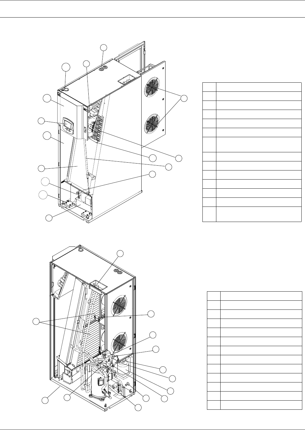
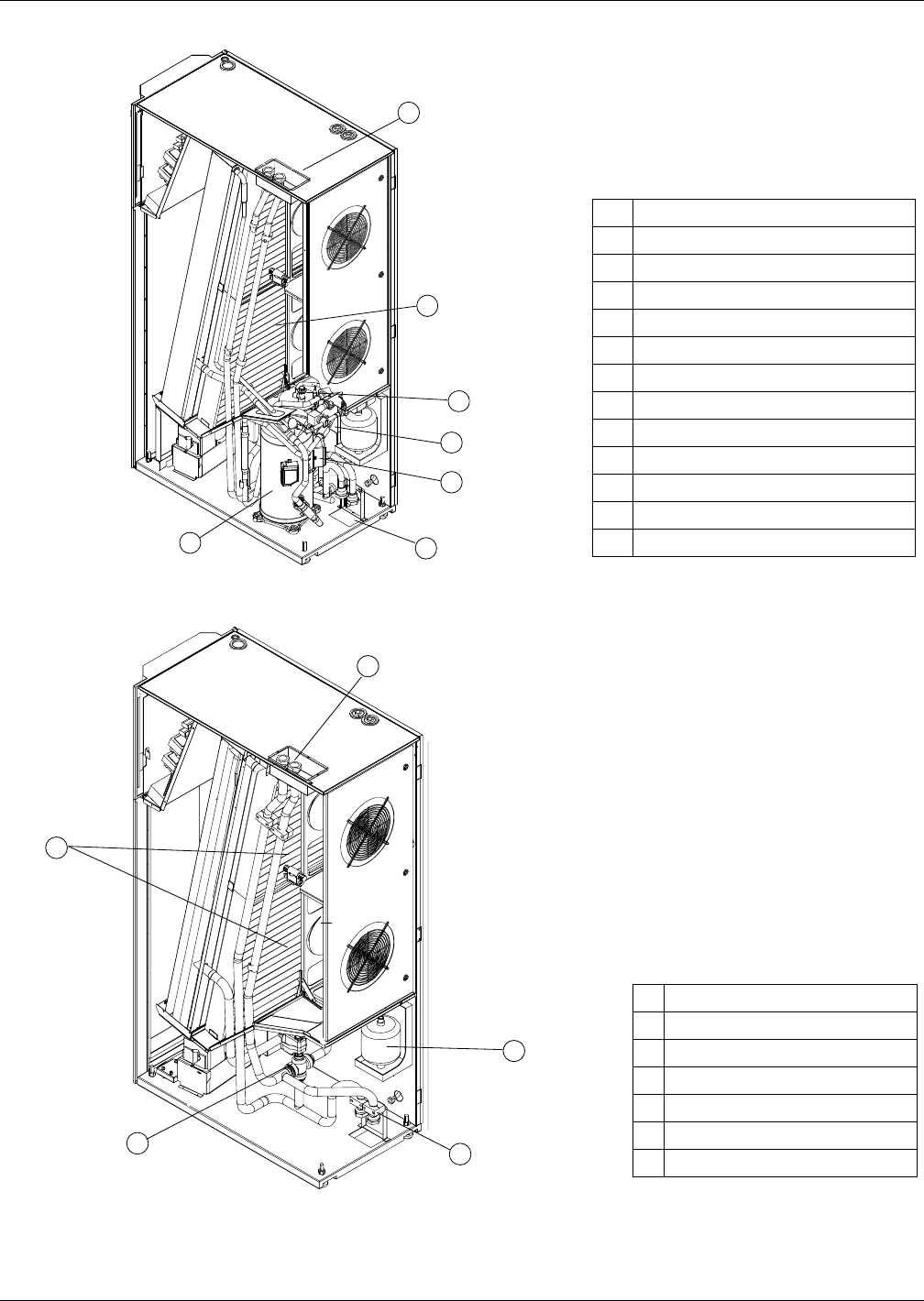
Figure 1 Component location, common components—All models
Figure 2 Component location - Liebert CR035RA, CR020RA air-cooled units
1 Liebert iCOM® control display
2 Electric box
3 Evaporator / CW coil
4 Condensate pump
5 Electric heaters
6 Humidifier distributor
7Top humidifier water supply,
condensate pump drain
8 Drain trays, two places
9 EC plug fans
10 Bottom electrical entrance
11 Serial tag inside door
12 Bottom condensate pump drain
13 Top electrical entrance
14 Supply air temperature sensor
location (sensor not shown)
1
2
11
3
12
10
4
8
8
6
5
9
13
7
14
Front
Rear
8
1
10
3
4
7
9
2
5
6
11
12
13
1 Thermostatic expansion valve
2 Solenoid valve
3 Sight glass
4 Filter dryer
7 Humidity/temperature sensor
8 Humidifier
9 Top refrigerant connections
10 Bottom refrigerant connections
11 Bottom humidifier water supply
12 Air filters
13 Bottom drain
14 Compressor
15 Vibasorber
Rear
Front
Liebert CRV Component Location
5Liebert
® CRV™
Figure 3 Component location - Liebert CR035RW, CR020RW water/glycol-cooled units
Figure 4 Component location - Liebert CR040RC chilled water units
2
3
1
4
5
6
7
1 Top water/glycol connections
2 Compressor
3 Brazed plate condenser
4 Bottom water/glycol connections
5 Water/glycol valve
6 Refrigerant receiver
7Air filters
8 Vibasorber
9 Thermostatic expansion valve
10 Sight glass
11 Filter dryer
12 Humidity/temperature sensor
13 Bottom humidifier water supply
2
3
1
5
4
1 Top CW connections
2Air filters
3 Three-way CW valve
4 Bottom CW connections
5 Humidifier
6 Humidity/temperature sensor
7 Bottom humidifier water supply
Liebert CRV Component Location
Liebert® CRV™6
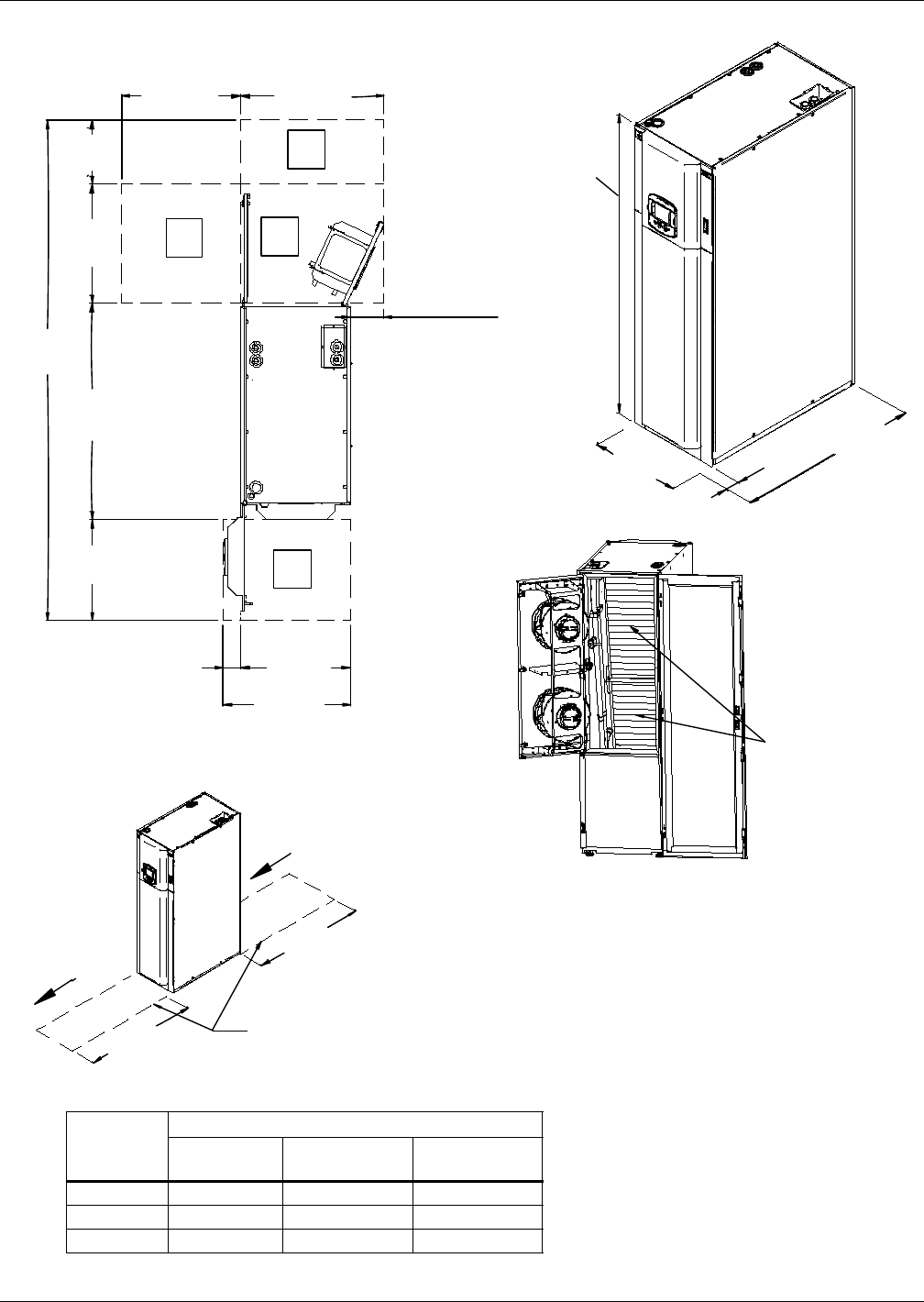
Figure 5 Overall dimensions / service area
Table 1 Dry weight, all model types, ± 5%
Model No.
Model Type
Air Cooled
lb (kg)
Water/Glycol
lb (kg)
Chilled Water
lb (kg)
CR020R 739 (335) 772 (350 —
CR035R 805 (365) 849 (385) —
CR040R — — 728 (330)
Source: DPN001791, Rev. 2
Only front or back
clearance required
B S
S
A
Rear
Rear
Access Required to Remove / Install
Entire Unit Within The Row
12"
(305mm)
3-15/16" (100mm)
13-3/4"
(350mm)
25-9/16"
(650mm)
46-1/4"
(1175mm)
27-9/16"
(700mm)
21-5/8"
(550mm)
Cold Air
Hot Air
107-5/16"
(2725mm)
25-9/16"
(650mm)
23-5/8"
(600mm)
3-15/16"
(100mm)
35-9/16"
(903mm)
23-5/8"
(600mm)
3"
(75mm)
78-3/4"
(2000mm)
46-1/4"
(1175mm)
Air
Filters
Front
Door Fully Open
Top
DPN1791
Rev. 2
InstallInstall
49"
(1245mm)
49"
(1245mm)
Introduction
7Liebert
® CRV™
2.0 INTRODUCTION
2.1 Product Description
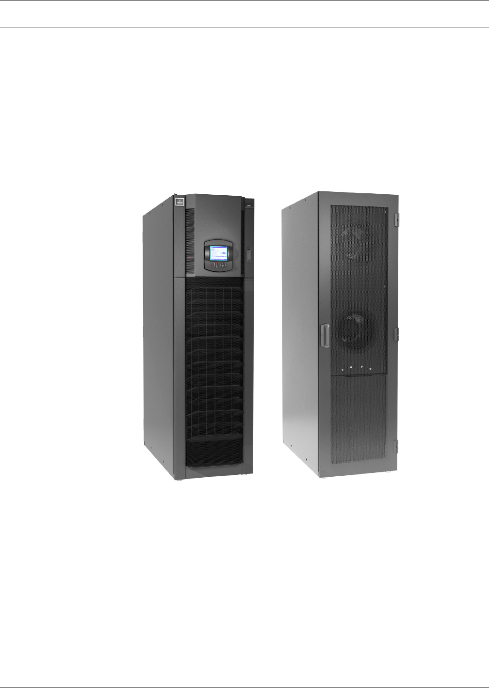
The Liebert CRV is a precision cooling unit available in compressorized (air-, water- or glycol-cooled)
and chilled water configurations to be installed within a row of high-density computing racks in a
“hot aisle-cold aisle” configuration.
Air enters the rear of the Liebert CRV from the hot aisle, is filtered, cooled and conditioned, then
discharged into the cold aisle. The Liebert CRV provides all the necessary functions of a standard
precision air conditioner, including cooling, heating, humidification, dehumidification, air filtration,
condensate management, temperature control, alarm monitoring and data communication. The
Liebert CRV is optimized for maximum cooling capacity in a minimal footprint.
Figure 6 Liebert CRV, front and rear views
RearFront
Inspection and Unpacking
Liebert® CRV™8
3.0 INSPECTION AND UNPACKING
NOTICE
Risk of overhead interference. Can cause unit and/or building damage.
The unit may be too tall to fit through a doorway while on the skid. Measure the unit and
doorway heights and refer to the installation plans prior to moving the unit to verify
clearances.
NOTICE
Risk of improper storage. Can cause unit damage.
Keep the unit upright, indoors and protected from dampness, freezing temperatures and
contact damage.
3.1 Equipment Inspection
After the Liebert CRV unit arrives and before it is unpacked, verify that the delivered equipment
matches the bill of lading. Examine the packaging for any signs of mishandling or damage. Inspect all
items for damage, visible or concealed. Report any damage immediately to the carrier and file a
damage claim. Send a copy of the claim to Emerson Network Power or your Emerson representative.
3.1.1 Packing Material
All material used to package this unit is recyclable. Please save this material for future
use or dispose of it appropriately.
3.2 Handling
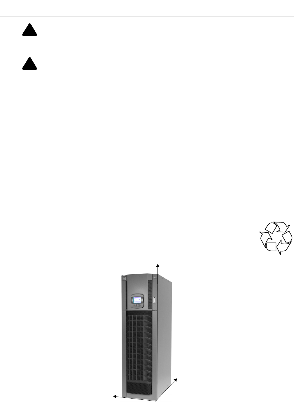
Figure 7 Liebert CRV center of gravity
!
WARNING
Risk of top-heavy unit falling over. Can cause equipment damage, personal injury and death.
Read all of the following instructions before attempting to move, lift or remove packaging
from the Liebert CRV.
!
CAUTION
Risk of sharp edges, splinters and exposed fasteners. Can cause personal injury.
Only properly trained and qualified personnel wearing appropriate safety headgear, gloves,
shoes and glasses should attempt to move, lift or remove packaging from the Liebert CRV or
prepare the unit for installation.
R
Z
Y
X
Inspection and Unpacking
9Liebert
® CRV™
• Always keep the packaged Liebert CRV upright and never leave it outdoors.
• Be aware of the center of gravity indicated on the package and in Table 2 below:
3.2.1 Handling the Unit While it is Packaged
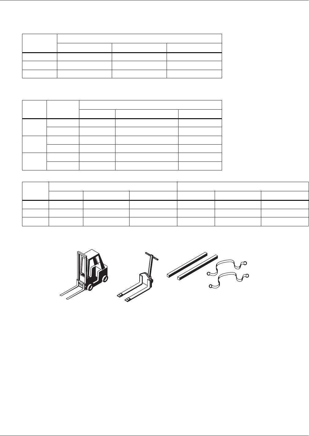
Figure 8 Recommended unit handling equipment
• Transport the packaged unit using a forklift, pallet jack or by overhead lift with slings and
spreader bars that are rated for the weight of the unit (see tables above).
• When using a forklift or pallet jack, make sure the forks (if adjustable) are spread to the widest
allowable distance to still fit under the skid. Make sure the fork length is suitable for the skid
length. Skid length is 60" (1524mm).
• Do not lift the packaged unit any higher than 4" (102mm). All personnel except those moving the
Liebert CRV must be kept 12' (3.7m) or more from the unit while it is being moved.
• If the unit must be lifted higher than 4" (102mm) all personnel not directly involved in moving the
Liebert CRV must be 20' (5m) or more from the unit.
Table 2 Center of gravity
Model no.
Distance from lower right front corner, ± 2 in. (51m)
X, in. (mm) Y, in. (mm) Z, in. (mm)
CR020 20 (508) 12 (305) 28 (711)
CR035 20 (508) 12 (305) 32 (813)
CR040 21 (533) 12 (305) 32 (813)
The center of gravity on the Liebert CRV varies with the options and the model's size.
Table 3 Weights without packaging
Model
No.
Electrical
Data
Weight ± 5%, lb (kg)
Air-Cooled Water/Glycol-Cooled Chilled Water
CR020 460/3/60 739 (335) 772 (350) —
208/3/60 739 (335) 772 (350) —
CR035 460/3/60 805 (365) 849 (385) —
208/3/60 805 (365) 849 (385) —
CR040 460/3/60 — — 728 (330)
208/3/60 — — 728 (330)
Table 4 Shipping weights
Model
No.
Domestic Packaging, lb (kg) Export Packaging, lb (kg)
Air Water/Glycol Chilled Water Air Water/Glycol Chilled Water
CR020 846 (384) 879 (399) — 953 (432) 986 (447) —
CR035 912 (414) 956 (434) — 1019 (462) 1063 (482) —
CR040 — — 835 (379) — — 942 (427)
Forklift
Pallet Jack
Spreader Bars
and Slings
Inspection and Unpacking
Liebert® CRV™10
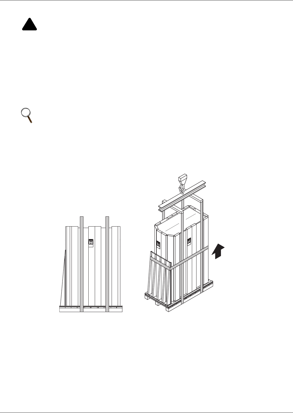
3.3 Moving the Unit Using Rigging
1. Use a pallet jack or forklift to raise the packaged unit.
2. Place slings under the skid runners, equally spacing the slings to make sure the unit is balanced
(see Figure 9).
3. Lower the unit and remove the pallet jack or forklift.
4. Connect the slings to the lifting device, using spreader bars or similar equipment to protect the
unit (see Figure 9).
5. Move the unit to its installation location. Two or more properly trained and qualified personnel
are required to move the Liebert CRV to its installation location.
6. Lower the Liebert CRV and remove the slings.
Figure 9 Moving the unit using rigging
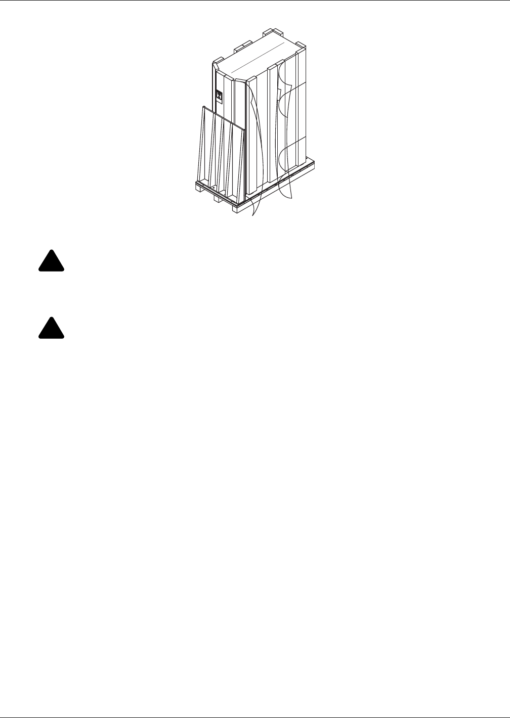
3.4 Unpacking the Liebert CRV
1. Remove the lag bolts securing ramp to skid.
2. Place the ramp and and the plastic bag with orange clips to the side for use in removing the unit
from the skid.
3. Remove the stretch film and corner/side packaging planks from around the unit.
4. Remove the unit bag when ready to install the unit.
!
CAUTION
Risk of sharp edges, splinters and exposed fasteners. Can cause personal injury.
Only properly trained and qualified personnel wearing appropriate safety headgear, gloves,
shoes and glasses should attempt to move, lift or remove packaging from the Liebert CRV or
prepare the unit for installation.
NOTE
Wrapping one or two more straps around the middle of the Liebert CRV will improve stability
when it is lifted.
197023
Rev. 4
Inspection and Unpacking
11 Liebert® CRV™
Figure 10 Unpacking the Liebert CRV
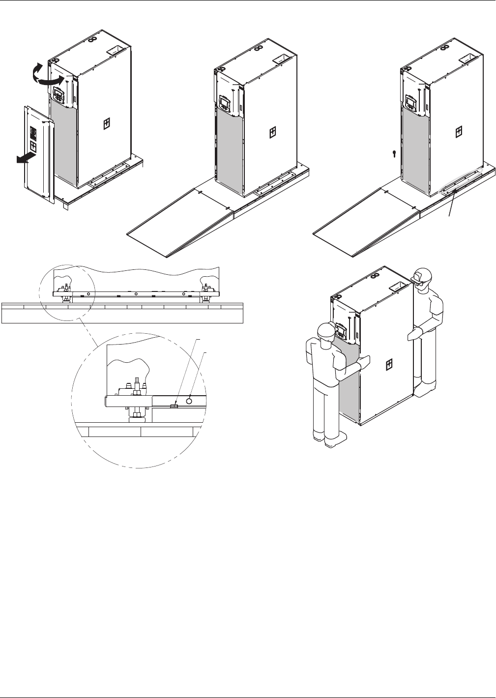
3.5 Removing the Unit from the Skid
1. Open the top panel door with the mounted control (refer to Figure 11).
2. Remove the bottom baffle panel assembly by removing the screws with a T30 Torx screwdriver.
3. Set the baffle panel assembly aside until the Liebert CRV is ready for it to be to reattached.
4. Close and latch the top panel door.
5. Place the ramp against the skid as shown in Figure 11.
6. Remove the orange clips from the plastic bag.
7. Insert clips into holes of the skid and ramp.
8. Remove the eight bolts, four on each side, that secure side tie-down brackets to skid.
Bolts can be removed using a 17mm socket wrench, open-end wrench or pliers.
9. Lower the four stabilizer feet until the side tie-down brackets no longer contact the skid.
10. Remove the six bolts, three on each side), that secure the side tie-down brackets to the unit base.
The bolts can be removed using a 13mm socket wrench, open-end wrench or pliers.
11. Remove the side tie-down brackets.
12. Remove the eight bolts, four on each side, that secure the lift block to the skid.
The bolts can be removed using a 17mm socket wrench, open-end wrench or pliers.
13. Remove the lift blocks from the skid.
14. Using the stabilizer feet, lower the unit to the skid.
15. Move the unit to its installation location. Two or more properly trained and qualified personnel
are required to move the Liebert CRV to its installation location.
!
WARNING
Risk of top-heavy unit falling over. Can cause equipment damage, personal injury and death.
Read all of the following instructions before attempting to move, lift or remove packaging
from the Liebert CRV.
!
CAUTION
Risk of sharp edges, splinters and exposed fasteners. Can cause personal injury.
Only properly trained and qualified personnel wearing appropriate safety headgear, gloves,
shoes and glasses should attempt to move, lift or remove packaging from the Liebert CRV or
prepare the unit for installation.
197023
Rev. 4
Inspection and Unpacking
Liebert® CRV™12
Figure 11 Removing the unit from the skid
3.6 Reattach the Baffle Panel
Once the Liebert CRV has been moved to where it will be installed, the baffle panel can be reattached.
1. Open top panel door (the one with the Liebert iCOM®).
2. Reattach the bottom baffle panel assembly with screws, using a T30 Torx drive.
3. Close and latch top panel door.
4 Bolts on Each Side
Secure the Tie-Down
Bracket to the Skid
M17 Socket
M13 Socket
Step 5
197023
Rev. 4
Step 1
Step 8
Step 8
Step 15
Prepare the Liebert CRV for Installation
13 Liebert® CRV™
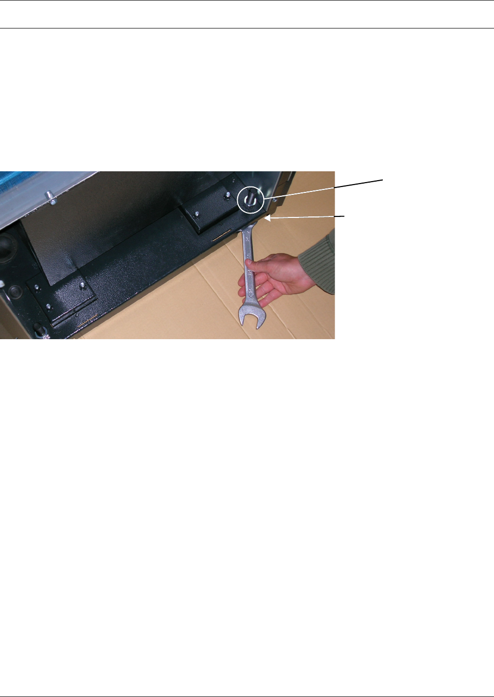
4.0 PREPARE THE LIEBERT CRV FOR INSTALLATION
1. Open the display door and remove the lower front baffle panel using a 10mm nutdriver or T30
Torx Bit to prepare for installation.
2. Open the rear panel, referring to Figure 10. The documents are located inside the display door.
3. After the Liebert CRV is in its final installation position, adjust the four base supports, or feet,
with an adjustable wrench. Ensure that the unit is level to avoid corrosion or health hazards
caused by condensate accumulation.
a. Turning the base supports, or feet, clockwise, will extend them, lifting the unit one corner at a
time.
b. Tighten the nut on the top of each adjustable foot, inside the Liebert CRV, to lock the feet.
Figure 12 Adjust leveling feet
Adjust the
height of the
feet
Tighten this nut after
the foot is adjusted to
the desired height

Piping
Liebert® CRV™14
5.0 PIPING
All fluid and refrigeration connections to the unit, with the exception of the condensate drain, are
sweat copper. Factory-installed piping brackets must not be removed. Field-installed piping must be
installed in accordance with local codes and must be properly assembled, supported, isolated and
insulated. Avoid piping runs through noise-sensitive areas, such as office walls and conference rooms.
Refer to specific text and detailed diagrams in this manual for other unit-specific piping
requirements.
All piping below the elevated floor must be arranged so that it offers the least resistance to airflow.
Careful planning of the piping layout under the raised floor is required to prevent the airflow from
being blocked. When installing piping on the subfloor, Emerson recommends installing the pipes in a
horizontal plane rather than stacked one above the other. Whenever possible, the pipes should be run
parallel to the airflow.
5.1 Fluid Connections
NOTICE
Risk of water leakage. Can cause severe property damage and loss of critical data center
equipment.
This unit requires a water drain connection. It may require an external water supply to
operate the humidifier. Improper installation, application and service practices can result in
water leakage from the unit.
Do not locate the Liebert CRV directly above any equipment that could sustain water damage.
Emerson recommends installing monitored leak detection equipment for the unit and supply
lines.
Piping
15 Liebert® CRV™
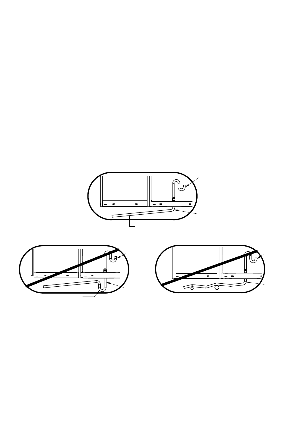
5.1.1 Condensate Piping—Field-Installed
• Do not reduce drain lines
• Do not expose drain line to freezing temperatures
• Drain line may contain boiling water. Use copper or other suitable material
• Drain line must comply with local building codes
• Emerson recommends installing under-floor leak detection equipment
Gravity Drain—Units Without Factory-Installed Condensate Pump
• 3/4" FPT drain connection is provided on units without optional factory-installed condensate
pump with infrared humidifier or no humidifier; 1-1/4" FPT connection is provided on units with
steam generating humidifier
• Pitch the drain line toward the drain a minimum of 1/8" (3mm) per 1 foot (305mm) of length
• Drain is trapped internally. Do not trap the drain external to equipment
• Drain line must be sized for 2 gpm (7.6 l/m) flow
NOTICE
Risk of improper piping connections. Can cause damage to the equipment and to the building.
The drain line has an internal trap and must not be trapped outside the unit or water may
back up into the drain pan and overflow the unit cabinet.
Figure 13 Gravity drain
Condensate Pump
• 1/2" copper sweat connection is provided on units with optional factory-installed condensate
pump
• Condensate pump is rated for approximately 6 GPM (22.7 l/min) at 30 ft (9m) total head
• Size piping based on available condensate head
5.1.2 Humidifier Supply Water—Optional Steam Generating Canister
• 1/4" supply line; maximum water pressure is 145psi (1000kPa)
• Fill valve is sized for pressure range of 30 to 120psi (207-827kPa)
• Do not supply steam generating humidifier with softened water
• Do not use hot water source
• Water conductivity must be in the range of 330-670 micro-siemens
CORRECT
INCORRECT
UNIT
Internal
Drain
External
Drain
Continuous Downward Slope
Internal
Drain
UNIT UNIT
External
Drain
Internal
Drain
External
Drain
These are external traps also, although
unintentional. Lines must be rigid enough
not to bow over top of other objects.
INCORRECT
Do Not Externally
Trap the Unit
DPN001556
Rev. 0

Piping
Liebert® CRV™16
5.1.3 Requirements of Systems Using Water or Glycol
These guidelines apply to the field leak checking and fluid requirements for field piping systems,
including Liebert chilled water, condenser (water or glycol) and drycooler circuits.
General Guidelines
• Equipment damage and personal injury can result from improper piping installation, leak check-
ing, fluid chemistry and fluid maintenance.
• Follow local piping codes, safety codes.
• Qualified personnel must install and inspect system piping.
• Contact a local water consultant regarding water quality, corrosion protection and freeze protec-
tion requirements.
• Install manual shutoff valves at the supply and return line to each indoor unit and drycooler to
permit routine service and emergency isolation of the unit.
NOTICE
Risk of frozen fluids. Can cause equipment damage and building damage.
Freezing system fluids can rupture piping. Complete system drain-down cannot be ensured.
When the field piping or unit may be exposed to freezing temperatures, charge the system
with the proper percentage of glycol and water for the coldest design ambient.
Automotive antifreeze is unacceptable and must NOT be used in any glycol fluid system.
NOTICE
Risk of corrosion. Can cause equipment damage.
Read and follow individual unit installation instructions for precautions regarding fluid
system design, material selection and use of field-provided devices. Liebert systems contain
iron and copper alloys that require appropriate corrosion protection.
Contact a local water consultant regarding water quality, corrosion and freeze protection
requirements.
Water chemistry varies greatly by location, as do the required additives, called inhibitors,
that reduce the corrosive effect of the fluids on the piping systems and components. The
chemistry of the water used must be considered, because water from some sources may
contain corrosive elements that reduce the effectiveness of the inhibited formulation.
Sediment deposits prevent the formation of a protective oxide layer on the inside of the
coolant system components and piping. The water/coolant fluid must be treated and
circulating through the system continuously to prevent the build up of sediment deposits and
or growth of sulfate reducing bacteria.
Preferably, surface waters that are classified as soft and are low in chloride and sulfate ion
content should be employed. Proper inhibitor maintenance must be performed in order to
prevent corrosion of the system. Consult glycol manufacturer for testing and maintenance of
inhibitors.
Commercial ethylene glycol (Union Carbide Ucartherm, Dow Chemical Dowtherm SR-1 and
Texaco E.G. Heat Transfer Fluid 100), when pure, is generally less corrosive to the common
metals of construction than water itself. It will, however, assume the corrosivity of the water
from which it is prepared and may become increasingly corrosive with use if not properly
inhibited.
NOTICE
Risk of no-flow condition. Can cause equipment damage.
Do not leave the unit in a no-flow condition.
Idle fluid allows the collection of sediment that prevents the formation of a protective oxide
layer on the inside of tubes. Keep unit switched ON and system pump operating.

Piping
17 Liebert® CRV™
Leak Checking of Unit and Field Piping
Liebert unit fluid systems are factory-checked for leaks and may be shipped with a nitrogen holding
charge. Liebert unit fluid circuits should be checked for leaks at installation as described below.
NOTE
During leak checking of field-installed piping, Emerson recommends that the unit be isolated
using field-installed shutoff valves. When the Liebert units are included in a leak test, use of
fluid for pressure testing is recommended. When pressurized gas is used for leak testing the
Liebert unit, the maximum recommended pressure is 30 psig (2 bars) and tightness of the unit
should be verified by pressure decay over time, (<2 psig/hour [0.3 bars/hour]) or sensing a
tracer gas with suitable instrumentation. Dry seals in fluid valves and pumps may not hold a
high gas pressure.

Refrigerant Connections
Liebert® CRV™18
6.0 REFRIGERANT CONNECTIONS
NOTICE
Risk of oil contamination with water. Can cause equipment damage.
The piping must not be open to the atmosphere for extended periods because the Liebert CRV
requires POE (polyol ester) oil. POE oil absorbs water at a much faster rate when exposed to
air than previously used oils. Because water is the enemy of a reliable refrigeration system,
extreme care must be used when opening systems during installation or service. If water is
absorbed into the POE oil, it will not be easily removed and will not be removed through the
normal evacuation process. If the oil is too wet, it may require an oil change. POE oils also
have a property that makes them act as a solvent in a refrigeration system. Maintaining
system cleanliness is extremely important because the oil will tend to bring any foreign
matter back to the compressor.
The Liebert CRV can be connected to a condenser through either the top or bottom of the unit. The
unit is piped for connections at the top of the unit as shown in Figure 14, with provision for
connection through the bottom of the unit.
Connecting through the bottom of the unit requires cutting the liquid and suction lines as shown in
Figure 15. Cutting these lines disconnects the top connections from the rest of the refrigeration system.
Air-cooled units are shipped with a holding charge of nitrogen.
!
WARNING
Risk of explosive discharge from high-pressure refrigerant. Can cause injury or death.
This unit contains fluids and/or gases under high pressure.
Relieve pressure before working with piping.
!
WARNING
Risk of refrigerant system rupture or explosion from overpressurization. Can cause
equipment damage, injury and death.
A pressure relief valve is required for compliance with the EU Pressure Equipment
Directive and may be required for compliance with local codes. If a discharge pressure relief
device is not provided with the condenser unit, the system installer must install one in the
high side of the refrigerant circuit and rated for a maximum of:
• 675psig (46.5bar) for water/glycol-cooled units
• 700psig (48.3bar) for air-cooled units
A shutoff valve must not be installed between the compressor and the field-installed relief
valve.
One or more additional pressure relief valves are required downstream of any and all
field-installed isolation. Do not isolate any refrigerant circuits from overpressurization
protection.
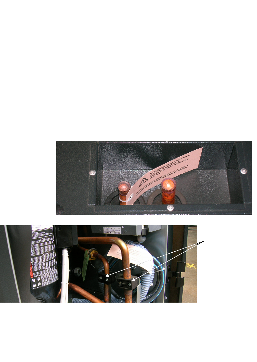
Refrigerant Connections
19 Liebert® CRV™
6.1 Piping Guidelines—Air-Cooled Units
• Indoor unit ships with a nitrogen holding charge; do not vent the evaporator until all refrigerant
piping is in place, ready for connection to the unit and condenser
• Use copper piping with high temperature brazed joints
• Isolate piping from building using vibration-isolating supports
• Refer to Tables 7 through 10 for piping sizes
• Refer to condenser installation manual for charging information
• Install traps on hot gas (discharge) lines at the base of vertical risers and every 15 feet (4.6m) of
vertical rise.
• See Table 6 for the allowable elevation difference between the condenser and the Liebert CRV.
• Consult factory if piping run exceeds 300 feet (91m) equivalent length
• Keep piping clean and dry, especially on units with R-410A refrigerant
• Avoid piping runs through noise-sensitive areas
• Do not run piping directly in front of airstream of any air conditioner
• Refrigerant oil – do not mix oil types
Refer to ASHRAE Refrigeration Handbook for general, good-practice refrigeration piping.
6.2 Refrigerant Piping—Air-Cooled Models
Figure 14 Top refrigerant piping connections
Figure 15 Bottom refrigerant piping connections
If using bottom
connections, cut
the pipes just
below the black
pipe clamps
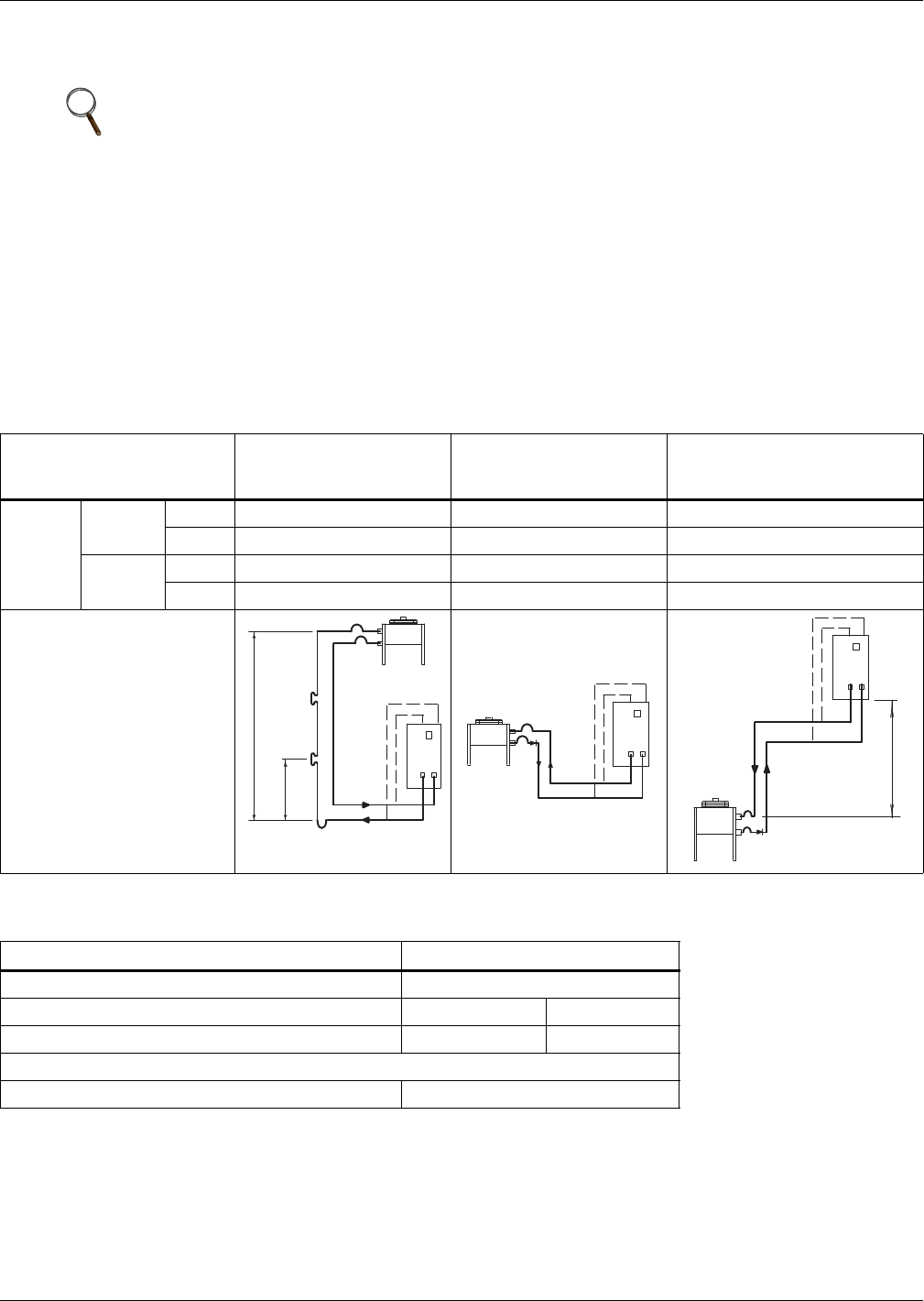
Refrigerant Connections
Liebert® CRV™20
6.2.1 General Layout
1. Piping must be Type ACR copper tubing and sized per Tables 7,8,9 and 10.
Use the shortest possible refrigeration pipelines to minimize the total charge of refrigerant and
the number of pressure drops.
2. Minimize the number of bends and make the bends the largest radius practical to prevent
constricting refrigerant flow.
3. Insulate the piping as specified in Table 5. If the pipes are installed next to electrical cables, they
must be isolated from the building using vibration-isolating supports to avoid damage to cable
insulation.
4. There must be at least one inch (25mm) separation between the gas and liquid pipelines. If this is
not possible, insulate both lines.
5. Support both horizontal and vertical pipes with vibration-damping clamps, which include rubber
gaskets. Place these clamps every 5 to 7 ft. (1.5 to 2m).
NOTE
All field-installed piping must comply with applicable national, state and local codes.
Table 5 Condenser positioning
Condenser
Position
Condenser Above
Liebert CRV
Condenser and
Liebert CRV
at Same Level
Condenser Below
Liebert CRV
(Not Recommended)
Insulation
Discharge
Line
Indoor necessary necessary necessary
Outdoor only for aesthetic reasons only for aesthetic reasons only for aesthetic reasons
Liquid
Line
Indoor only for aesthetic reasons only for aesthetic reasons no (expose to cold under-floor air)
Outdoor only for aesthetic reasons only if exposed to sun only if exposed to sun
Layout
** See Table 6
Table 6 Liebert CRV position relative to the remote condenser
Parameter Maximum Distances, ft. (m)
From Liebert CRV to condenser 300 (91.4) equivalent length
From Liebert CRV to VFD condenser Above: 60 (18.3) Below: 15 (4.5)
From Liebert CRV to Liebert Lee-Temp™ condenser Above: 60 (18.3) Below: 0 (0)
Requirements
Oil traps on vertical line of gas refrigerant Every 15 (4.6)
15 ft. (4.6m)
(See *) Gas
Liquid
* Oil traps every 15 ft. (4.6m)
of vertical piping
Room Unit
(See **)
Gas
Liquid
Room Unit
Liquid
Room Unit
(See**)
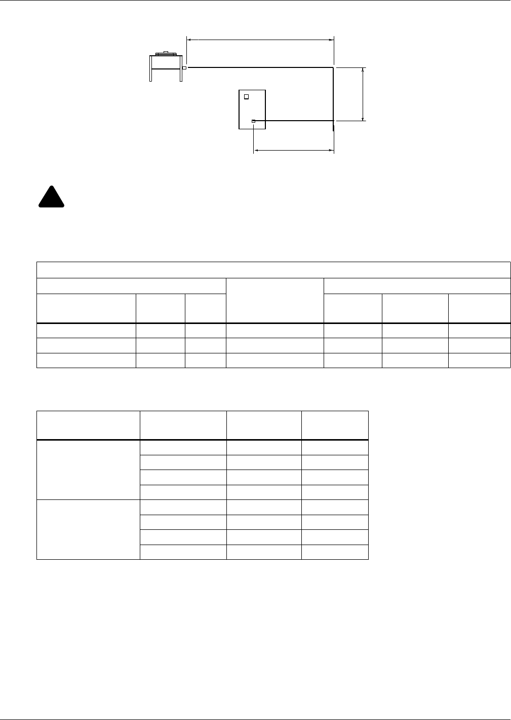
Refrigerant Connections
21 Liebert® CRV™
Figure 16 Pipeline air conditioner - condenser
6.2.2 Pipe Diameter and Thickness
!
WARNING
Risk of explosive discharge. Can cause equipment damage, injury or death.
Use only Type ACR copper tubing sized per Tables 7,8,9 and 10 for pipes connecting the
Liebert CRV and the condensing unit.
Table 7 Piping and refrigerant sizes for Liebert Lee-Temp™ condensers with R-410A
Condenser Piping Connection Sizes
Condenser Connections, O.D., in.
Liebert Lee-Temp
Size, in. (mm)
Liebert Lee-Temp Connections, I.D., in.
Condenser Model # Hot Gas Liquid
Hot Gas
Tee
Liquid To
L-T Valve
Receiver
Out
DCSL28K 1-1/8 7/8 9 x 36 (229 x 914) 1-1/8 5/8 7/8
DCSL60K 1-1/8 7/8 11 x 36 (279 x 914) 1-1/8 5/8 7/8
DCSL90K 1-1/8 7/8 11 x 48 (279 x 1219) 1-1/8 5/8 7/8
Source: DPN001623, Rev. 6, Page 3
Table 8 Recommended refrigerant line sizes for Liebert Lee-Temp condensers with R-410A Cu, OD
Liebert CRV Model #
Total Equivalent
Length, ft. (m)
Hot Gas Line,
in. (mm)
Liquid Line,
in. (mm)
CR020RA
50 (15.2) 3/4 (19.1) 5/8 (15.9)
100 (30.5) 3/4 (19.1) 5/8 (15.9)
150 (45.7) 3/4 (19.1) 5/8 (15.9)
300 (91.4) 7/8 (22.2)* 3/4 (19.1)
CR035RA
50 (15.2) 7/8 (22.2) 3/4 (19.1)
100 (30.5) 7/8 (22.2) 3/4 (19.1)
150 (45.7) 7/8 (22.2) 3/4 (19.1)
300 (91.4) 1-1/8 (28.6)* 7/8 (22.2)
Consult factory for proper line sizing for runs longer than 300 ft. (91.4m) equivalent length.
* Must downsize vertical riser one trade size (1-1/8” to 7/8” or 7/8” to 3/4”).
Source: DPN001623, Rev. 6, Page 3
B
C
CDT
COND
A
(Distance) D = A + B + C
CDT = Conditioner
COND = Condenser
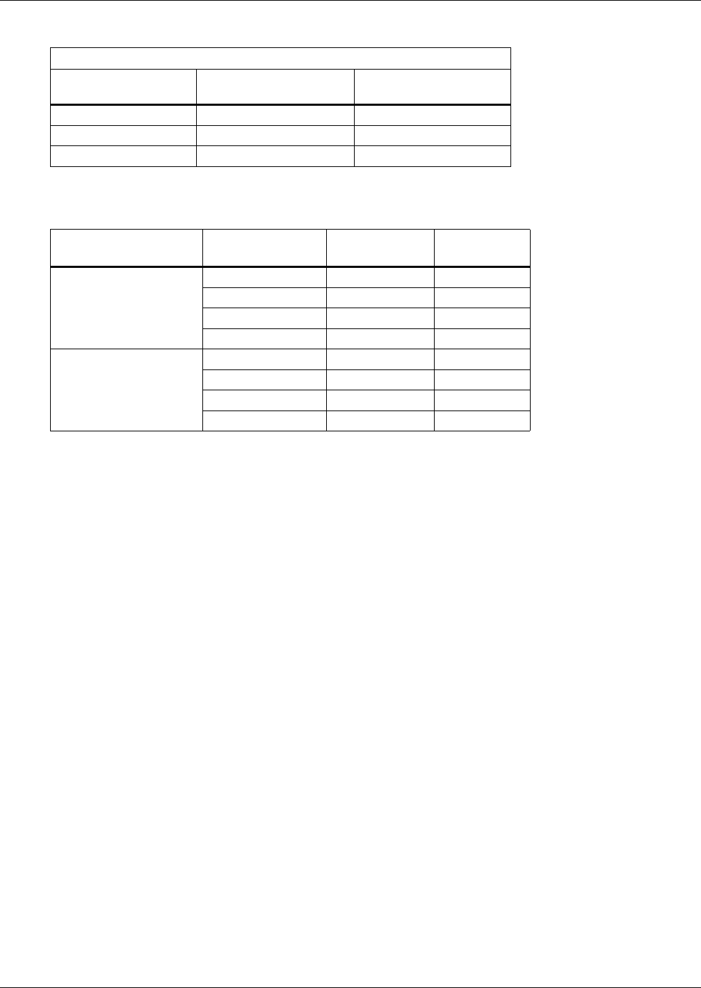
Refrigerant Connections
Liebert® CRV™22
Table 9 Piping and refrigerant sizes for Liebert air-cooled, VFD control condensers with R-410A
Condenser Piping Connection Sizes, Cu, O.D.
Condenser Model #
Entering Hot Gas
Line, in. (mm)
Returning Liquid
Line, in. (mm)
TCSV28K 1-1/8 (28.6) 7/8 (22.2)
TCSV60K 1-1/8 (28.6) 7/8 (22.2)
TCSV90K 1-1/8 (28.6) 7/8 (22.2)
Source: DPN001624, Rev. 5, Page 3
Table 10 Recommended refrigerant line sizes for Liebert air-cooled, VFD control condensers
with R-410A, Cu, OD
Liebert CRV Model #
Total Equivalent
Length, ft. (m)
Hot Gas Line,
in. (m)
Liquid Line,
in. (m)
CR020RA
50 (15.2) 3/4 (19.1) 5/8 (15.9)
100 (30.5) 3/4 (19.1) 5/8 (15.9)
150 (45.7) 3/4 (19.1) 5/8 (15.9)
300 (91.4) 7/8 (22.2) 23/4 (19.1)
CR035RA
50 (15.2) 7/8 (22.2) 3/4 (19.1)
100 (30.5) 7/8 (22.2) 3/4 (19.1)
150 (45.7) 7/8 (22.2) 3/4 (19.1)
300 (91.4) 1-1/8 (28.6) 27/8 (22.2)
1. Consult factory for proper line sizing for runs longer than 300 ft. (91.4m) equivalent length.
2. Must downsize vertical riser one trade size (1-1/8" to 7/8" or 7/8" to 3/4" ).
Source: DPN001624, Rev. 5, Page 3

Refrigerant Connections
23 Liebert® CRV™
6.2.3 Installing Piping
The following operations must be carried out by an experienced refrigeration technician.
NOTICE
Risk of oil contamination with water. Can cause equipment damage.
The piping must not be open to the atmosphere for extended periods because the Liebert CRV
requires POE (polyol ester) oil. POE oil absorbs water at a much faster rate when exposed to
air than previously used oils. Because water is the enemy of a reliable refrigeration system,
extreme care must be used when opening systems during installation or service. If water is
absorbed into the POE oil, it will not be easily removed and will not be removed through the
normal evacuation process. If the oil is too wet, it may require an oil change. POE oils also
have a property that makes them act as a solvent in a refrigeration system. Maintaining
system cleanliness is extremely important because the oil will tend to bring any foreign
matter back to the compressor.
1. When installing the refrigerant piping, note the following:
•Brazing:
• All joints must be brazed.
• Avoid butt brazes by using couplings or swaging one of the pipes with a swaging tool.
• Ensure that all brazed joints are leak-free.
• Flow dry nitrogen through the pipes during brazing.
• Always use large-radius curves (bending radius at least equal to pipe diameter). Bend the pipes
as follows:
• soft copper: bend by hand or use bending device;
• hard copper: use preformed curves.
• To minimize oxidation, avoid overheating the pipes when brazing.
2. Connect the pipes to the condenser:
• Condensers with butt-brazed pipe connections: Cut the pipe, enlarge it and braze it to the pipe-
line.
Respect the direction of refrigerant flow. (See labels on refrigerant.)
3. Wash out the pipelines as follows:
a. Plug up the free ends of the pipes.
b. Connect a helium or nitrogen cylinder, fitted with a reducer (max. pressure 10 bar), to the
1/4" SAE Schrader valve of the condenser.
c. Pressurize the pipes with helium or nitrogen.
d. Unplug the pipes instantaneously.
e. Repeat Steps a through d several times.
This operation is especially important when hard copper piping is used.
4. Open all the shutoff valves on the room unit.
5. Discharge the room unit pressurized with helium (at 1 bar) by opening the charge valves so that
all the branches of the circuit are discharged (e.g., on the receiver, on the low pressure side and on
the compressor delivery).
6. Debraze the bottoms from the connections of the room unit.
7. Fix (braze) the pipes to the connections on the air conditioner.
8. Connect the refrigerant safety pressure relief valve to the outdoors with a 16 mm (5/8") copper
pipe. Only water/glycol units have a indoor relief valve. Air cooled units do not have an indoor
pressure relief valve.
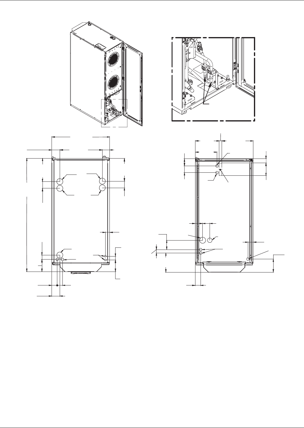
Refrigerant Connections
Liebert® CRV™24
Figure 17 Connections—air-cooled models
LVT LVT
RG
RL
RL
GD or CP
RG
Piping and electrical connections available at the top and bottom of unit.
Air-cooled systems may require oil to be added in the field to allow
sufficient compressor lubrication.
Top Connections
Unsolder when
connecting
through bottom
Bottom Connections
(possible with raised floor)
Rear
DPN001792
Rev. 2
HS
CP
CR
GDH
or HS
4-13/16"
(122.2mm)
23-5/8"
(600mm)
2-1/8" (54mm)
LVB LVB2
HVT
HVB
8-7/8"
(226mm)
1-1/8" (28mm)
7-13/16"
(199mm)
3-1/16"
(77mm)
5"
(127mm)
1-3/4"
(44mm)
5-1/8"
(130mm)
9-3/4"
(248mm)
12-3/4"
(325mm)
2-15/16"
(74mm)
2-3/16" (56mm)
2-11/16"
(69mm)
9-5/16"
(237mm)
3-1/16"
(77mm)
2-11/16"
(69mm)
2-11/16"
(69mm)
2-15/16"
(74mm)
3-1/4"
(83mm)
3-13/16"
(97mm)
5-3/8"
(136mm)
1-3/8"
(35mm)
2-1/8" (54.7mm)
1-3/4"
(45mm)
1-3/4"
(45mm)
1-1/2"
(38mm)
46-1/4"
(1175mm)
3-1/4" (83mm) 17-5/16"
(440mm)
9-1/2"
(242mm)

Refrigerant Connections
25 Liebert® CRV™
Table 11 Unit connections, air-cooled models
Unit Connections CR20A (50Hz) CR35A (50Hz) CR20A (60Hz) CR35A (60Hz)
RL Refrigerant Liquid
Line Inlet 12mm O.D. Cu Sweat 16mm O.D. Cu Sweat 1/2" O.D. Cu Sweat 5/8" O.D. Cu Sweat
RG Refrigerant Gas
Line Outlet 16mm O.D. Cu Sweat 22mm O.D. Cu Sweat 5/8" O.D. Cu Sweat 7/8" O.D. Cu Sweat
GD Gravity Coil Pan Drain 20mm I.D. 1" MPT
GDH Gravity Humidifier Drain 22mm I.D. N/A
CP Condensate Pump 1/2" GAS F 1/2" FPT
HS Humidifier Supply 1/2" GAS F (top connection)
3/4" GAS F (bottom connection)
1/2" FPT (top connection)
1/4" Compression Fitting (bottom connection)
HVT High Voltage
Top Connection
Combination Knockout
Hole Diameter 1-3/8" (35mm)
1-3/4" (44.5mm) and 2-1/2" (63.5mm)
Combination Knockout Hole
Diameter 1-3/8" (35mm)
1-3/4" (44.5mm) and 2-1/2" (63.5mm)
HVB
High Voltage Bottom
Entrance (feed through
the base of the unit)
Hole Diameter 2-1/2" (63.5mm) Knockout Hole Diameter 2-1/2" (63.5mm)
LVT Low Voltage
Top Connection Hole Diameter 7/8" (22mm) 2 places Knockout Hole Diameter 7/8" (22mm)
2 places
LVB
Low Voltage Bottom
Entrance (feed through
the base of the unit)
Hole Diameter 1-7/64" (28mm) 2 places Knockout Hole Diameter 1-3/32" (27.8mm)
2 places
LVB
2
Low Voltage Bottom
Entrance (feed through
the base of the unit)
—Knockout Hole Diameter 1-3/4" (44.5mm)
1 place
Source: DPN001792, Rev.2
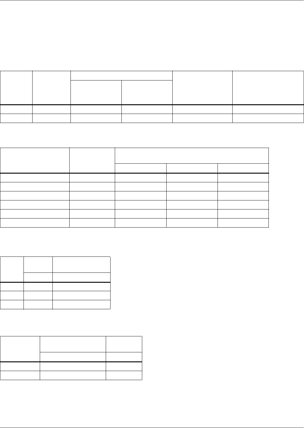
Refrigerant Connections
Liebert® CRV™26
6.3 Vacuum and Refrigerant Charge
NOTICE
Risk of improper refrigerant charge. Can cause equipment damage and reduced efficiency.
Check the refrigerant type to be used on the data plate of the air conditioner and on the
refrigerating compressor.
Topping up is requested for short pipeline, too, due to the extra-charge of refrigerant.
The air conditioner is supplied pressurized with helium at 1 bar.
Table 12 R-410A refrigerant and oil charge for air-cooled models
Model
Base
Refrigerant
Charge 1
lb (kg)
Base Oil Charge 1
Max. System
Refrigerant Charge
before Oil Addition,
lb (kg)
Weight of Oil to Add for
Every 10lb (4.5kg) of
Refrigerant over Max
System Charge,
oz (kg)
Initial Oil
Charge
oz (kg)
Max. Topping
Up
oz (kg)
CR020RA 7 (3.2) 60 (1.68) 56 (1.57) 38 (17.1) 1.6 (.045)
CR035RA 10 (4.5) 110 (3.08) 106 (2.97) 28 (12.6) 4 (.113)
1. The recommended oil is EMKARATE RL 32-3MA.
Table 13 Refrigerant charge 1
External Pipe Diameter
in (mm)
Gas R-410A,
lb/feet (kg/m)
Liquid (+), at Different Condensing
Temperatures - R-410A, lb/ft (kg/m)
95°F (35°C) 115°F (46°C) 135°F (57°C)
1/2" x 0.049 (12 x 1) - 0.05 (0.08) 0.05 (0.07) 0.04 (0.07)
9/16" x 0.049 (14 x 1) 0.0084 (0.0124) 0.07 (0.11) 0.07 (0.11) 0.06 (0.10)
5/8" x 0.049 (16 x 1) 0.0114 (0.0169) 0.10 (0.16) 0.10 (0.14) 0.09 (0.13)
3/4" x 0.049 (18 x 1) 0.0149 (0.0221) 0.14 (0.20) 0.13 (0.19) 0.11 (0.17)
7/8" x 0.065 (22 x 1.25) 0.0232 (0.0346) — — —
1-1/8" x 0.065 (28 x 1.5) 0.0392 (0.0584) — — —
(+) Liquid pressure and density varies according to condensing temperature (see refrigerant tables).
1. For distance D see Figure 16 Pipeline air conditioner - condenser
Table 14 Air-cooled condenser refrigerant charge
Model
VFD
Liebert Lee-Temp™
(inc. receiver)
lb (kg) lb (kg)
28 K 7 (3.2) 41 (18.6)
60 K 16 (7.3) 75 (34.0)
90 K 25 (11.3) 109 (49.4)
Table 15 Refrigerant and oil charge for water-cooled models
Model
R-410A
Refrigerant Charge
Initial Oil
Charge 1
lb (kg) oz (kg)
CR020RW 13.0 (5.9) 60 (1.68)
CR035RW 17.0 (7.7) 110 (3.08)
The air conditioner is supplied complete with refrigerant and oil.
1. The recommended oil is EMKARATE RL 32-3MA.
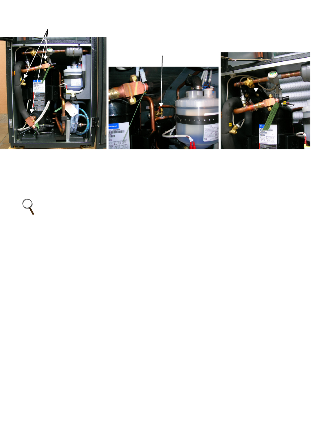
Refrigerant Connections
27 Liebert® CRV™
Figure 18 Connections for vacuum creation and refrigerant charge
6.3.1 Evacuation Air-Cooled Models
Variable Fan Speed Control Leak Check and Evacuation Procedure
Proper leak check and evacuation can be accomplished only with all system solenoid valves open and
check valves accounted for.
1. If unit power is available, open the unit liquid line solenoid valves using the evacuation function
for System #1 in the diagnostic section of the Liebert iCOM® control (see Figure 68). If unit
power is not available, a field-supplied 24VAC / 75VA power source must be directly connected to
the unit solenoid valve.
2. Connect refrigerant gauges to the suction rotalock valves and discharge line Schrader valves.
3. Open the service valves and place a 150 PSIG (1034 kPa) of dry nitrogen with a tracer of
refrigerant. Check system for leaks with a suitable leak detector.
4. After completion of leak testing, release the test pressure (per local code) and pull an initial deep
vacuum on the system with a suitable pump.
5. After four hours, check the pressure readings and, if they have not changed, break vacuum with
dry nitrogen. Pull a second and third vacuum to 250 microns or less. Recheck the pressure after
two hours. After completing this step, proceed to Variable Fan Speed Charging on page 28.
NOTE
The system include a factory-installed check valve and an additional downstream Schrader
valve with core in the compressor discharge line. Proper evacuation of the condenser side of the
compressor can be accomplished only using the downstream Schrader valve. See piping
schematic.
Suction and Supply Line Connections
Liquid Line Connection
Thermostatic Valve Connection

Refrigerant Connections
Liebert® CRV™28
Variable Fan Speed Charging
1. Check unit nameplate for refrigerant type to be used. Unit control configurations differ depending
on refrigerant type.
2. Charging the system with refrigerant requires the unit to be in an operational state..
3. Calculate the amount of charge for the system. Refer to the unit, condenser and refrigerant line
charge data in Tables 12,13 and 14.
4. Weigh in as much of the system charge as possible before starting the unit.
NOTICE
Risk of improper refrigerant charging. Can cause equipment damage.
Refrigerant R-410A is a blend of two components and must be introduced and charged from
the cylinder only as a liquid.
When adding liquid refrigerant to an operating system, it may be necessary to add the
refrigerant through the compressor suction service valve. Care must be exercised to avoid
damage to the compressor. Emerson recommends connecting a sight glass between the
charging hose and the compressor suction service valve. This will permit adjustment of the
cylinder hand valve so that liquid can leave the cylinder while allowing vapor to enter the
compressor.
5. Turn on unit disconnect switch. Operate the unit for 30 minutes using the charging function in
the diagnostic section of the Liebert iCOM® control (see Figure 68). The charging function
operates the compressor at full capacity and energizes the blower motor and the liquid line
solenoid valve. The reheat and humidifier are disabled. A minimum 20psig (138kPa) must be
established and maintained for the compressor to operate. The charging function can be reset as
many times as required to complete unit charging.
6. Charge the unit until the liquid line sight glass becomes clear, then add one additional pound
(2.2kg) of refrigerant.
7. As head pressure builds, the variable fan speed controlled condenser fan begins rotating. The fan
will run at full speed when sufficient head pressure is developed—fan starts to rotate at 310psig
(2137kPa) and is full speed at 400psig (2758kPa).
NOTE
A digital scroll compressor will have a clear sight glass only when operating at 100% capacity.
When operating below 100%, the sight glass may show bubbles with each 15-second unloading
cycle.
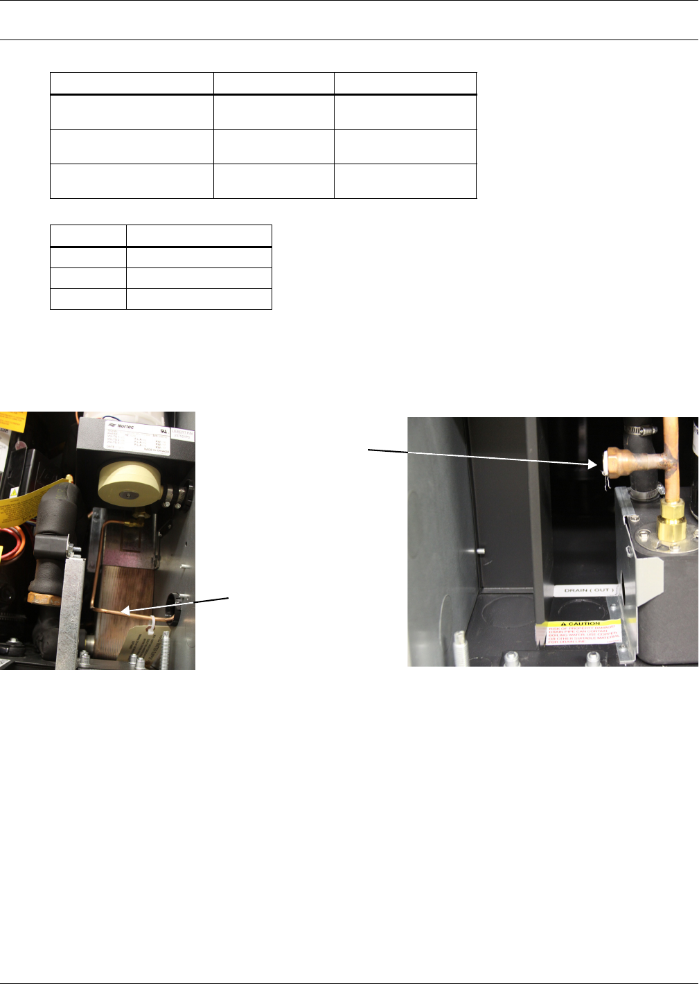
Water Connections
29 Liebert® CRV™
7.0 WATER CONNECTIONS
7.1 Water Connections—Supply Humidifier and Drain Water, All Models
Units with a condensate pump and humidifier are preset to be connected from the top. If floor
connections are used, the water lines can be intercepted at the following points:
Figure 19 Water connection points, bottom entry
• Condensate drain without pump:
• Use tubing rated to carry water up to 212°F (100°C) copper, PVC or flexible polythene tubing.
• Allow a 2% gradient toward the drain.
• Drain is trapped internally. Do not trap the drain external to the equipment.
• Fill the drain trap with water.
• Humidifier (optional): See Appendix A - Humidifier.
Table 16 Water connection options
Liebert CRV Option Top Connections Bottom Connections
Condensate Pump
and Humidifier Available Available
Condensate Pump
and No Humidifier Available Available
No Condensate Pump
and No Humidifier Not Available Available
Table 17 Volume of CRV internal water circuits
Model Volume
CR020RW 4.8 liters, 1.27 gallons
CR035RW 5.7 liters, 1.51 gallons
CR040RC 17.6 liters, 4.65 gallons
Condensate
Pump Drain
Humidifier Water Supply

Water Connections
Liebert® CRV™30
7.2 Glycol Mixture
Add ethylene glycol or propylene glycol to the circuit in the percentages shown in Table 18.
7.3 Water Connections: Water/Glycol-Cooled Models
The unit must receive cooling water as follows:
• From an external cooling water source, in open circuit.
• Using a drycooler, in closed circuit.
1. Connect the piping as shown in Appendix D - Refrigeration and Hydraulic Circuits.
2. Use hoses connected with three-piece joints to the condenser water inlet and outlet couplings.
3. Install a 16-20 mesh strainer on the water/glycol supply to the Liebert CRV. The strainer is
needed to prevent particles in the water from entering the unit’s heat exchanger.
4. Place shutoff ball valves at the conditioner inlet and outlet to allow easy maintenance.
5. Install a water drain system at the lowest point in the circuit.
6. Fully drain the piping before connecting it to the air conditioner.
7.3.1 Notes for Open-Circuit Applications
• Use the unit with mains or well water. Do not use water from an evaporative cooling tower unless
the water hardness is controlled.
• The water pressure must be 29-145psi (2-10 bar). If water pressure is outside this range, contact
Emerson for technical support.
• The required water flow at different temperatures is available from Emerson.
• If water temperature is very low, insulate both pipes.
7.3.2 Notes for Closed-Circuit Applications
The installation in Figure 3 is illustrative only; for individual installations follow the project diagram.
• Install a pump system calculated on the basis of the flow and total head of the system (see site
plan data) and controlled by the compressor running (see label on the Liebert CRV).
• Insulate both pipes.
•Very important: Add water and ethylene glycol to the circuit when the ambient temperature is
below 32°F (0°C); refer to the Liebert CRV technical data manual, SL-11978). Do not exceed the
nominal operating pressure of the circuit components.
• Bleed air out of the circuit.
Table 18 Glycol mixtures
Glycol Percentage *
by Volume
Ethylene Glycol -
Freezing Temperature, °F (°C)
Propylene Glycol -
Freezing Temperature, °F (°C)
0% 32 (0) 32 (0)
10% 25.3 (-3.7) 28.9 (-1.7)
20% 16 (-8.9) 18.7 (-7.4)
30% 3.7 (-15.7) 8.4 (-13.1)
40% -12.6 (-24.8) -6.7 (-21.5)
* Freezing temperatures may vary slightly among commercially available glycol products; refer to manufacturer’s specifications.
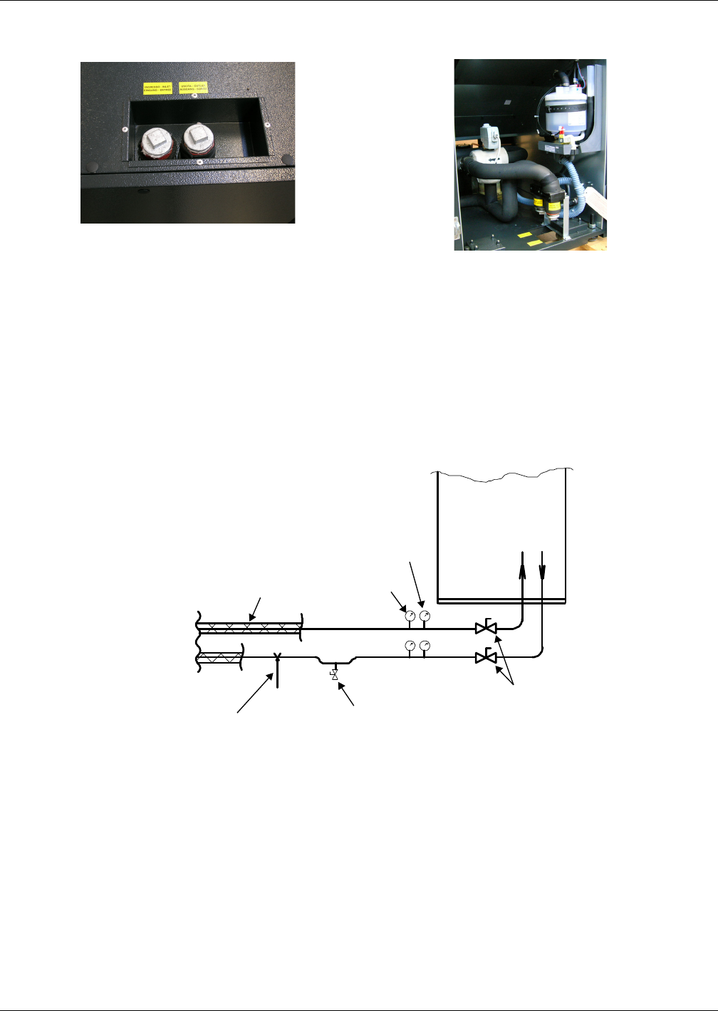
Water Connections
31 Liebert® CRV™
7.4 Chilled Water Connections: Chilled Water Units
Figure 20 Chilled water connections
Refer to Figure 21 when performing these installation steps:
• Use copper tubing or steel pipe.
• Place the tubing on supporting saddles.
• Insulate both tubes
• Install shutoff ball valves on the inlet and outlet pipes to ease maintenance.
• Install optional thermostats and pressure gauges on the inlet and outlet pipes.
• Install a water drain tap at the lowest point in the circuit.
• Fill the circuit with water or glycol.
Figure 21 Chilled water circuit
Top Connections
Bottom Rear Connections
Tubing Support Water Drain Tap
Ball
Valves
Thermostat
Pressure
Gauge
Insulation
Liebert CRV
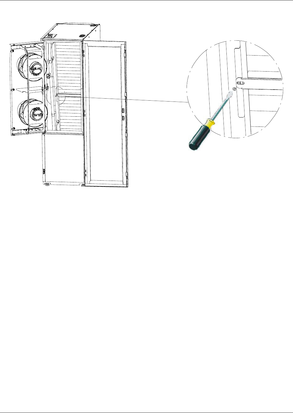
Water Connections
Liebert® CRV™32
Figure 22 Air bleeding valve position CW
REAR VIEW
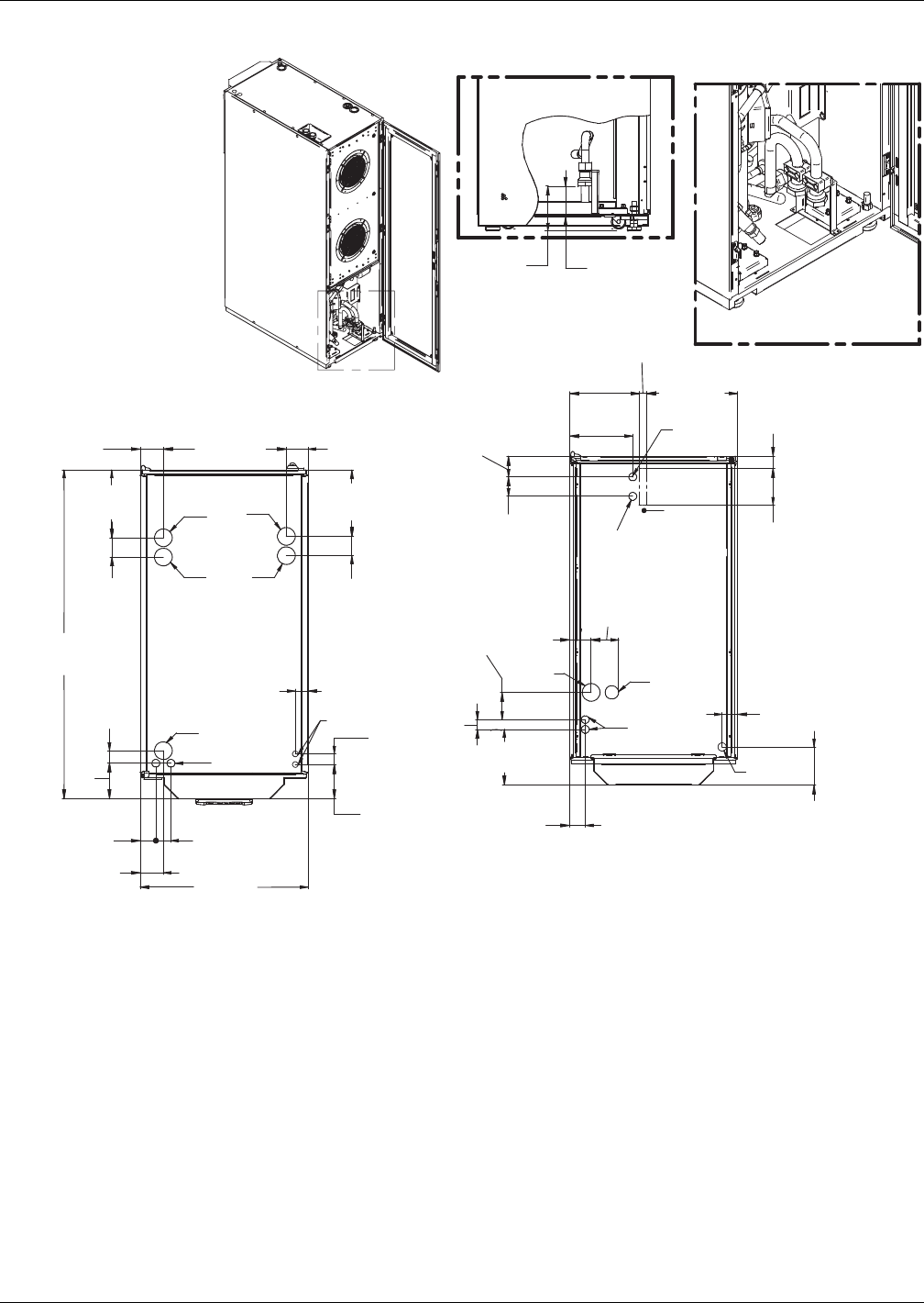
Water Connections
33 Liebert® CRV™
Figure 23 Connections—water/glycol models
HVT
LVT
LVT
HS
CP
CR
CS
GDH
or HS
CR
Piping and electrical
connections available at
the top and bottom of unit.
* Install a 35 mesh strainer, in an easily accessible location, on the Water/Glycol Supply
to prevent particles from entering the heat exchanger. Strainer bypass valves are
recommended to allow the strainer to be cleaned while maintaining flow to the cooling unit.
Bottom Connections
(possible with raised floor)
DPN001793
Rev. 2
Top Connections
Rear
2-3/16"
(56mm)
4-13/16"
(122.2mm)
2-3/16" (56mm)
23-5/8"
(600mm)
2-1/8"
(54mm)
5"
(127mm)
GD
or CP
LVB
LVB
HVB
CS
7-13/16"
(199mm)
8-7/8"
(226mm)
1-1/8"
(28mm)
4-1/8"
(105mm)
6-1/8"
(155mm)
7-13/16"
(199mm)
3-1/16"
(77mm)
5-1/8"
(130mm)
5-3/8"
(136mm)
2-1/8" (54.7mm)
1-3/4"
(44mm)
12-3/4"
(325mm)
2-15/16"
(74mm)
2-11/16"
(69mm)
2-11/16"
(69mm)
2-11/16"
(69mm)
9-5/16"
(237mm)
9-3/4"
(248mm)
3-7/8"
(98mm)
1-1/2"
(38.1mm)
3-1/4" (83mm)
3-13/16"
(97mm)
1-3/8"
(35mm)
1-3/4"
(45mm)
1-3/4" (45mm)
46-1/4"
(1175mm)
3-1/4"
(83mm)
17-5/16"
(440mm)
9-1/2"
(242mm)

Water Connections
Liebert® CRV™34
Table 19 Unit connections, water/glycol-cooled models
Unit Connections CR20W (50Hz) CR35W (50Hz) CR20W (60Hz) CR35W (60Hz)
CS Water/Glycol Coolant Supply 32mm GAS F 1-1/4" FPT
CR Water/Glycol Coolant Return 32mm GAS F 1-1/4" FPT
GD Gravity Coil Pan Drain 20mm I.D. 1" MPT
GDH Gravity Humidifier Drain 22mm I.D. N/A
HS Humidifier Supply 1/2" GAS F (top connection)
3/4" GAS F (bottom connection)
1/2" FPT (top connection)
1/4" Compression Fitting
(bottom connection)
CP Condensate Pump 1/2" GAS F 1/2" FPT
HVT High Voltage Top Connection
Combination Knockout Hole
Diameter 1-3/8" (35mm)
1-3/4" (44.5mm) and 2-1/2" (63.5mm)
Combination Knockout Hole
Diameter 1-3/8" (35mm)
1-3/4" (44.5mm) and 2-1/2" (63.5mm)
HVB High Voltage Bottom Entrance
(feed through the base of the unit) Hole Diameter 2-1/2" (63.5mm) Knockout Hole Diameter 2-1/2" (63.5mm)
LVT Low Voltage Top Connection Hole Diameter
7/8" (22mm) 2 places
Knockout Hole Diameter
7/8" (22mm) 2 places
LVB Low Voltage Bottom Entrance
(feed through the base of the unit)
Hole Diameter 1-7/64" (28mm)
2 places
Knockout Hole Diameter
1-3/32" (27.8mm) 2 places
LVB2 Low Voltage Bottom Entrance
(feed through the base of the unit) —Knockout Hole Diameter
1-3/4" (44.5mm) 1 place
Source: DPN001793, Rev. 2
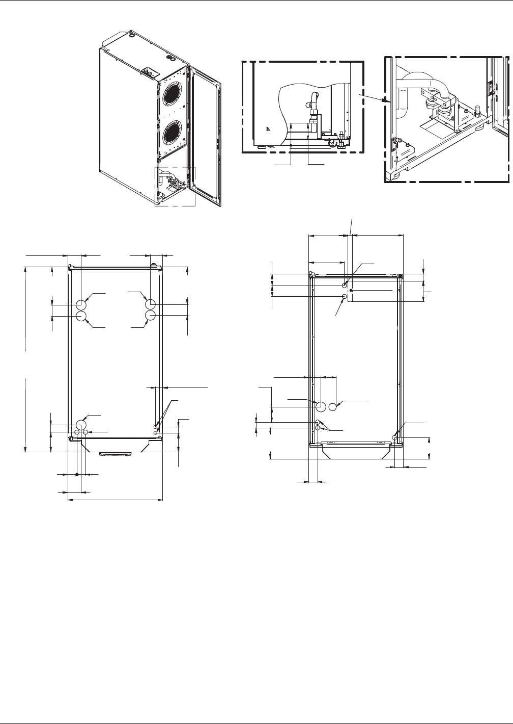
Water Connections
35 Liebert® CRV™
Figure 24 Connections—chilled water models
Piping and electrical
connections available
at the top and bottom
of the unit.
TOP CONNECTIONS
BOTTOM CONNECTIONS
(possible with raised floor)
REAR
LVT
LVT
HVT
LVB LVB2
GDH or HS
CWR
CWR
CWS
CWS
HS
CP
GD or CP
46-1/4"
(1175)
5"
(127)
3-1/4" (83) 17-5/16"
(440) 3-1/16" (77)
9-5/16"
(237)
1-3/4"
(45)
9-1/2"
(242)
2-11/16"
(69)
1-1/8"
(28)
2-3/16" (56)
3-13/16"
(97)
3-1/16")
(77)
3-7/8"
(98)
HVB
9-3/4"
(248)
8-7/8"
(226)
(325)
12-3/4"
2-11/16"
(69)
2-11/16"
(69)
2-3/16"(56)
4-1/8"
(105)
6-1/8"
(155)
2-1/8" (54.71)
2-1/8" (54)
5-3/8" (136.01)
23-5/8" (600)
3-1/4" (83)
1-3/4" (45.2)
1-1/2"
(38.1)
4-13/16"
(122.16)
7-13/16"
(199)
1-3/8"
(35)
1-3/4"
(44)
5-1/8"
(130)
2-15/16"
(74)
DPN001794
Rev. 2
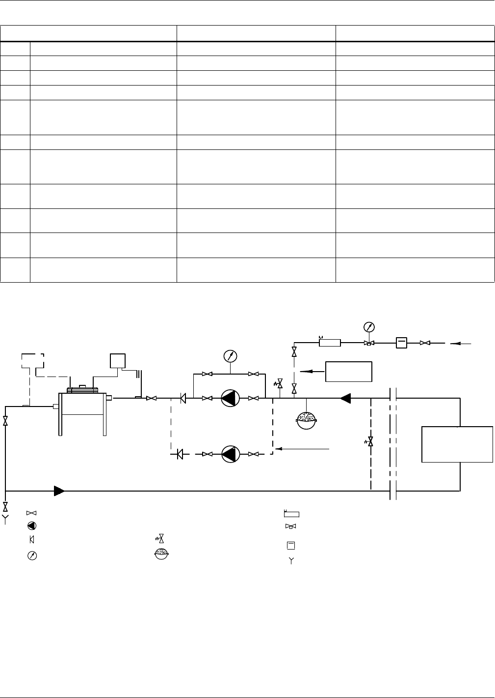
Water Connections
Liebert® CRV™36
Figure 25 Recommended drycooler Installation
Table 20 Unit connections, chilled water models
Unit Connections CR040C (50 Hz) CR040C (60 Hz)
CWS Chilled Water Supply 32mm GAS F 1-1/4" FPT
CWR Chilled Water Return 32mm GAS F 1-1/4" FPT
GD Gravity Coil Pan Drain 20mm I.D. 1" MPT
GDH Gravity Humidifier Drain 22mm I.D. N/A
HS Humidifier Supply 1/2" GAS F (top connection)
3/4" GAS F (bottom connection)
1/2" FPT (top connection)
1/4" Compression Fitting
(bottom connection)
CP Condensate Pump 1/2" GAS F 1/2" FPT
HVT High Voltage Top Connection
Combination Knockout Hole
Diameter 1-3/8" (35mm)
1-3/4" (44.5mm) and 2-1/2" (63.5mm)
Combination Knockout Hole
Diameter 1-3/8" (35mm)
1-3/4" (44.5mm) and 2-1/2" (63.5mm)
HVB High Voltage Bottom Entrance
(feed through the base of the unit)
Hole Diameter
2-1/2" (63.5mm)
Knockout Hole Diameter
2-1/2" (63.5mm)
LVT Low Voltage Top Connection Hole Diameter
7/8" (22mm) 2 places
Knockout Hole Diameter
7/8" (22mm) 4 Places
LVB Low Voltage Bottom Entrance
(feed through the base of the unit)
Hole Diameter
1-7/64" (28mm) 2 places
Knockout Hole Diameter
1-3/32" (27.8mm) 2 Places
LVB2 Low Voltage Bottom Entrance
(feed through the base of the unit) —Combination Knockout Hole
Diameter 1-3/4" (44.5mm) 1 Place
Source: DPN001794, Rev. 2
APPLIANCE
TSHTC
Filling
Water
(optional)
HTC
TS
Shutoff Valve
Pump
Check Valve
Gauge
Thermostat
Variex (50Hz Opt.)
Safety Valve
Expansion Tank
Air Separator
Charge Group (Filter,
Reducer, Check Valve)
Filling Meter
Drain (at Lowest Point)
(*)
Standby Pump
Standby Pump
Pressure-Operated Bypass
See hydraulic drawings in the Appendix D
Disconnect
After Charge
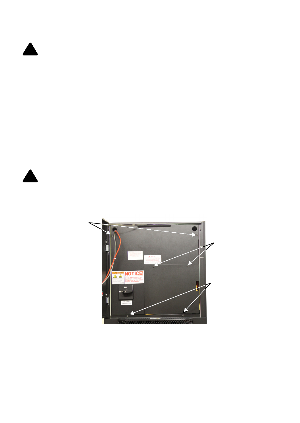
Electrical Connections
37 Liebert® CRV™
8.0 ELECTRICAL CONNECTIONS
8.1 Electrical connections
Figure 26 Remove electrical panel and lower front panel
!
WARNING
Arc flash and electric shock hazard. Can cause injury and death.
Disconnect local and remote power supplies and wear appropriate personal protective
equipment per NFPA 70E before working within.
Before proceeding with installation, read all instructions, verify that all the parts are included
and check the nameplate to be sure the voltage matches available utility power.
The Liebert iCOM® microprocessor does not isolate power from the unit, even in the Unit Off
mode.
Some internal components require and receive power even during the Unit Off mode of the
Liebert iCOM control.
The factory-supplied optional disconnect switch is inside the unit. The line side of this switch
contains live hazardous voltage potential.
Install and open a remote disconnect switch and verify with a voltmeter that live hazardous
voltage potential is not present inside the unit cabinet before working within. Refer to the
unit electrical schematic.
Follow all national and local codes.
!
WARNING
Risk of electric shock. Can cause injury or death.
This unit has a high leakage current potential. Proper earth ground connection per national
and local codes is required before connection to the electric power supply.
Remove these bolts
to access low voltage
electrical panel
Remove these bolts
to access high voltage
electrical panel
Remove these bolts to open
lower front baffle panel
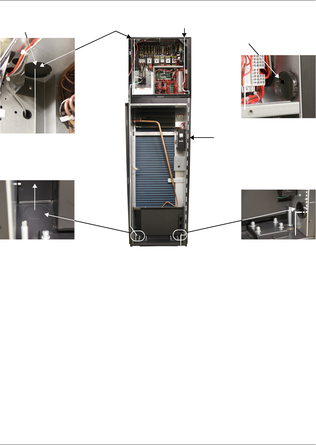
Electrical Connections
Liebert® CRV™38
Figure 27 Power and control cable entry points and routing
Before proceeding with the electrical connections, ensure that:
• all electrical components are undamaged
• all terminal screws are tight
• the supply voltage and frequency are as indicated on the unit
8.1.1 Power Supply Cable Connections
• Connect the cable to the line inlet terminal board.
• Use the appropriate cable size for the current draw, supply voltage and installation type.
• Protect the supply using a backup fuse or circuit breaker.
• Do not fit the supply cable in the raceways inside the machine electric board.
• Use only multipolar cables with sheath (CEI20-22).
Wiring Connections
• Remote On/Off connections must be provided by the installer.
• The General Alarm terminals allow remote alarm signalling.
In case of short circuit, check the affected switch for sticking and replace it if necessary.
See electrical data in Appendix B - Electrical Data.
High Voltage
Top Entry Port
Low Voltage Channel
opening provides access
to the Liebert IntelliSlot®
card housing
Low voltage cables are
routed through a channel
in the side panel to
connect the bottom of the
unit to the electrical panel
High voltage
bottom entry port
Low voltage bottom
entry port
High Voltage Top
Entry Port
Low Voltage Top
Entry Port
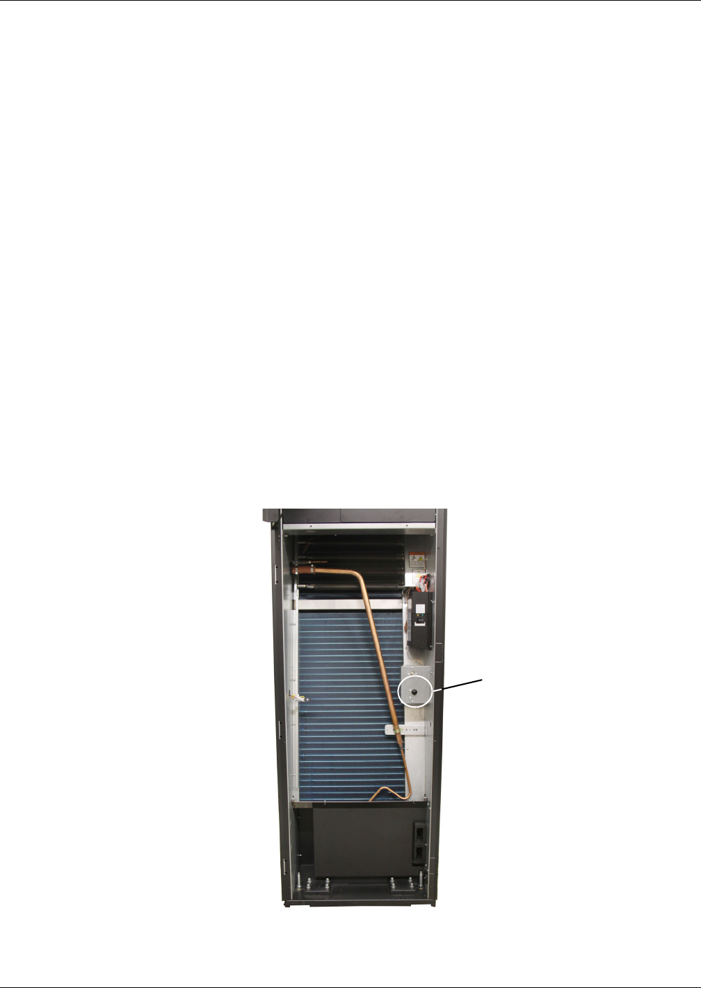
Electrical Connections
39 Liebert® CRV™
8.2 Protective Features of the Electrically Commutated Fans
The EC fans are protected against:
• Overtemperature of electronics
• Overtemperature of motor
• Locked rotor protection
• Short circuit at the motor output
When any of these failures occurs, the motor stops, electronically, with no potential for separation,
and the status relay is released.
The unit does not restart automatic automatically. To reset the alarm, the power supply must be
switched Off for 20 minutes once motor is at standstill.
• Input power undervoltage detection:
If the utility power falls below 3ph/290VAC (typical value) for 5 seconds or longer, the motor is
switched Off, electronically, with no potential for separation, and the status relay is released.
When the utility voltage returns to a correct value, the motor restarts automatically.
• Phase failure recognition:
If one phase fails for 5 seconds or longer, the motor is switched Off, electronically, with no poten-
tial for separation, and the status relay is released.
When all three phases return to correct values, the motor restarts automatically in 10 to 40 sec-
onds.
The power supply for an external speed-setting potentiometer is protected against short-circuiting.
The motor is overload-protected via motor current limitation.
8.3 Protective Features of Electrical Heaters
Figure 28 Electrical heating with temperature sensor protection
When the temperature sensor detects overtemperature of electrical heating, the thermal protection
turns Off the current. To reset the thermal protection, push the button on the front of the unit (see
Figure 28).
Temperature
sensor
protection

Startup
Liebert® CRV™40
9.0 STARTUP
9.1 Initial Startup
To start the Liebert CRV:
1. Open all valves in the refrigeration circuit according to the instruction label attached to the valve.
2. W Models Only: Open all valves in the water circuit according to the instruction label attached
to the valve.
3. Ensure that the refrigerant charge is correct (see 6.0 Refrigerant Connections).
4. Using a leak detector, verify that there are no refrigerant leaks. If any leaks are detected, repair
them and recharge as described in 6.0 Refrigerant Connections.
5. At least 4 hours before startup, close the main switch and the compressor switch on the electrical
panel.
6. Verify that the crankcase heater is working.
7. Check to ensure that there are no water leaks.
8. If an external condenser or drycooler is installed, start it by supplying power to it.
9. Close all MCBs on the electrical panel.
10. Check the supply voltage on all phases.
11. Check the supply voltage on all phases for the external condenser or drycooler, if fitted.
12. Start the unit by pressing the On/Off switch.
13. Check the amp draw of all components (see 8.0 Electrical Connections).
14. Check the amp draw of the external condenser/drycooler, if fitted.
15. If the compressor makes a loud, unusual noise, invert the electrical connections of the phases
supplying the corresponding digital scroll compressor, which accepts only one direction of
rotation.
16. Ensure that the fans rotate in the correct direction (see arrow on fan).
17. Ensure that all control system settings are correct and that there are no alarms (see Figure 48).
18. W Models Only: Verify the water flow is adequate.
19. W Models Only: For closed circuit units, ensure that the water pump starts when the
compressor starts.
!
WARNING
Risk of hair, clothing and jewelry entanglement with high speed rotating fan blades. Can
cause equipment damage, serious injury or death.
Keep hair, jewelry and loose clothing secured and away from rotating fan blades during unit
operation.
!
WARNING
Risk of contact with rotating fan blades. Can cause injury or death.
The Liebert CRV’s fan blades will continue spinning after the unit is shut Off. Wait until the
fan blades have stopped before working on the unit.
NOTE
The default setting for the Liebert iCOM® control is for stand-alone operation. The stand-alone
mode allows users to turn on the unit simply by rotating the main switch on the electrical
panel. The yellow LED on the Liebert iCOM will light after the unit is turned on because
electrical power is present.
If the LED does not light:
• check the electrical panel power supply
• check the protection devices (e.g., thermal switches)
• check the fuses.
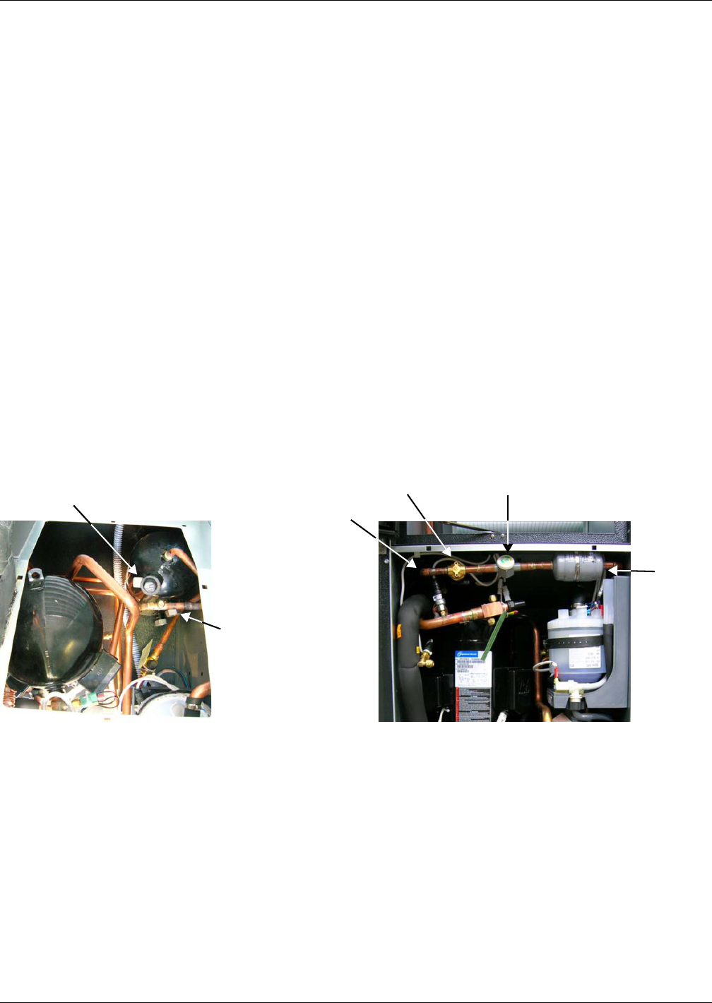
Startup
41 Liebert® CRV™
Checks to Perform after Startup
Once the system is operating under load, check the various components, as follows:
1. Verify that the fans are operating properly.
2. Ensure that the temperature and relative humidity are being controlled, and that the humidifier
(optional) and heating steps (optional) operate when required.
3. Ensure that the compressor operates when required.
4. Ensure that the fan operation controller on the external condenser/drycooler (if fitted) is
calibrated correctly, and that it controls the fan operation.
5. Record all of the following on the warranty inspection form:
a. All component voltages and current draws
b. All air / water temperatures indoor and outdoor
c. All refrigerant and water / glycol pressures,
d. All levels of refrigerant and oil in sight glasses
e. Record refrigerant pressure switch settings and operating pressures
f. Record superheat and sub-cooling.
9.2 Automatic Restart
If desired, the unit will automatically restart on the return of power after a supply interruption (see
Figure 90).
To avoid an automatic cold restart of the compressor if a power interruption of several hours is
expected, stop the unit before the blackout. After power returns, allow the compressor to preheat
before restarting the unit.
Figure 29 Refrigerant line components
Liquid Receiver Valve
Filter
Dryer
Inlet
Schrader
Valve
Filter
Dryer
Sight Glass
Solenoid Valve
Thermostatic
expansion
valve
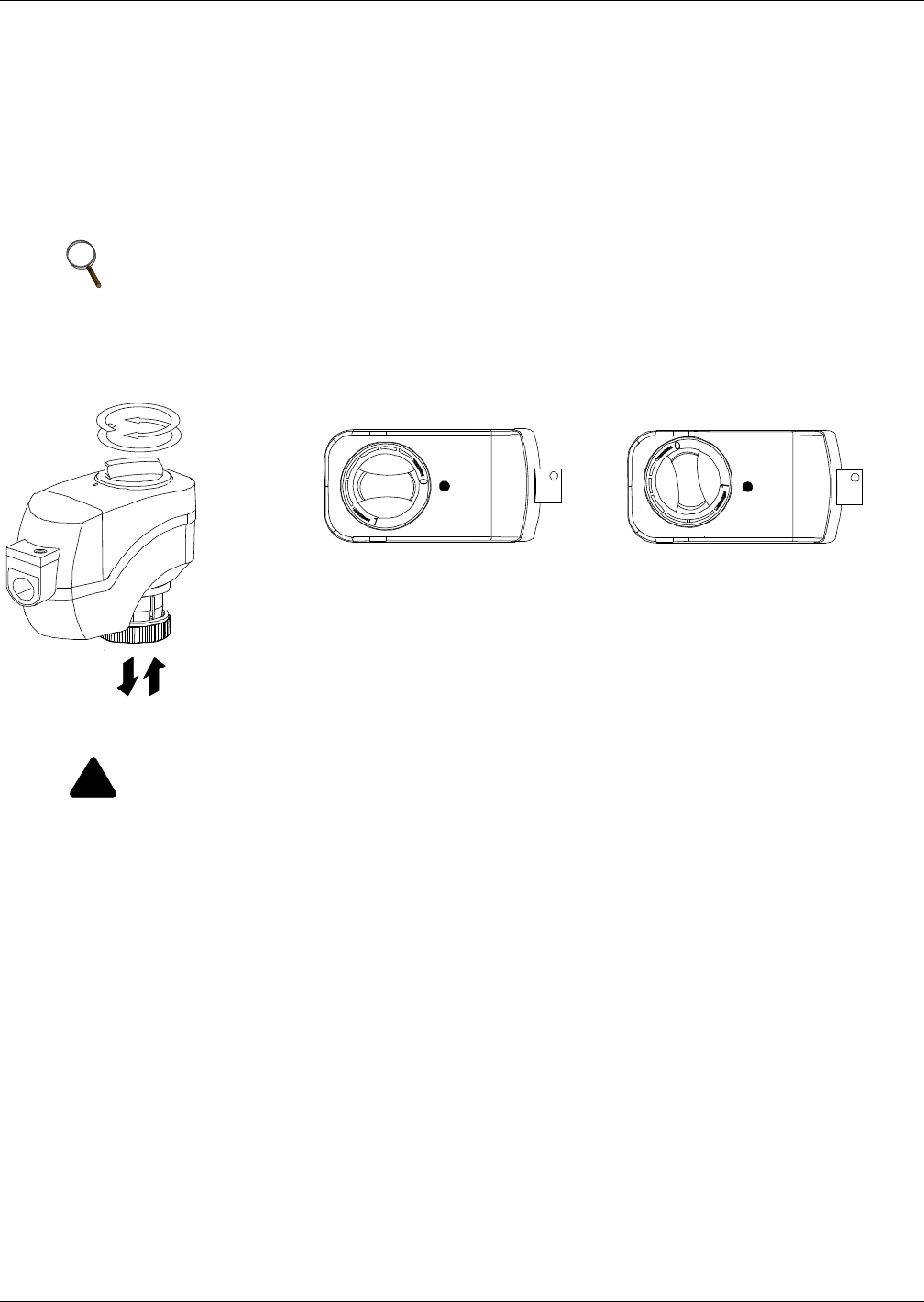
Startup
Liebert® CRV™42
9.3 Chilled Water Valve: Chilled Water Models
The 3-way valve controls the chilled water flow and operates as follows (refer to Figure 4):
• When the valve is fully open (i.e., maximum chilled water flow), the actuator slot is set to “1.”
• When the valve is closed (i.e., no chilled water flow), the actuator slot is set to “0.”
The valve running time is set to the value specified in the control manual.
For more details, see the technical bulletin for chilled water valves and related actuators. Technical
bulletins are enclosed with documentation onboard the unit.
Figure 30 Position of the chilled water valve actuator (for 2- or 3-way valve)
9.4 Adjust Baffles to Direct Air Properly
The Liebert CRV has been equipped with an adjustable, modular supply air baffle system. The baffles
should be adjusted prior to start-up to direct air towards the racks the cooling unit is intended to
condition. Ideally, these should be the same racks the cooling unit is pulling hot air from. The baffles
can be readjusted at any time as cooling needs change.
The Liebert CRV is shipped with the baffles in an alternating pattern to direct cold air left and right.
This configuration should be used when the cooling unit is located between racks. If a Liebert CRV is
installed at the end of a row, all the baffles should be adjusted to blow air down the cold-aisle, toward
the racks. The baffle segments at the top of the panel will direct more air than the segments at the
bottom. The supply air will travel the furthest when all baffle segments are pointed in the same
direction, left or right.
NOTE
1. In the unlikely event of control system failure, the valve can be manually controlled with
the rotary knob. It can be used to drive the actuator into any position between 0 and 1.
2. When the actuator stem is completely down, the valve is open and chilled water coil is
supplied.
!
WARNING
Risk of electric shock. Can cause injury or death.
Disconnect all local and remote electric power supplies before working within.
Ensure that the Liebert CRV is shut down and power has been disconnected before beginning
any work on the unit.
0
1
0
1
Position indicator on
0 = CLOSED valve
(3-way valve: bypass open)
Position indicator on
1 = OPEN valve
(3-way valve: by-pass closed)
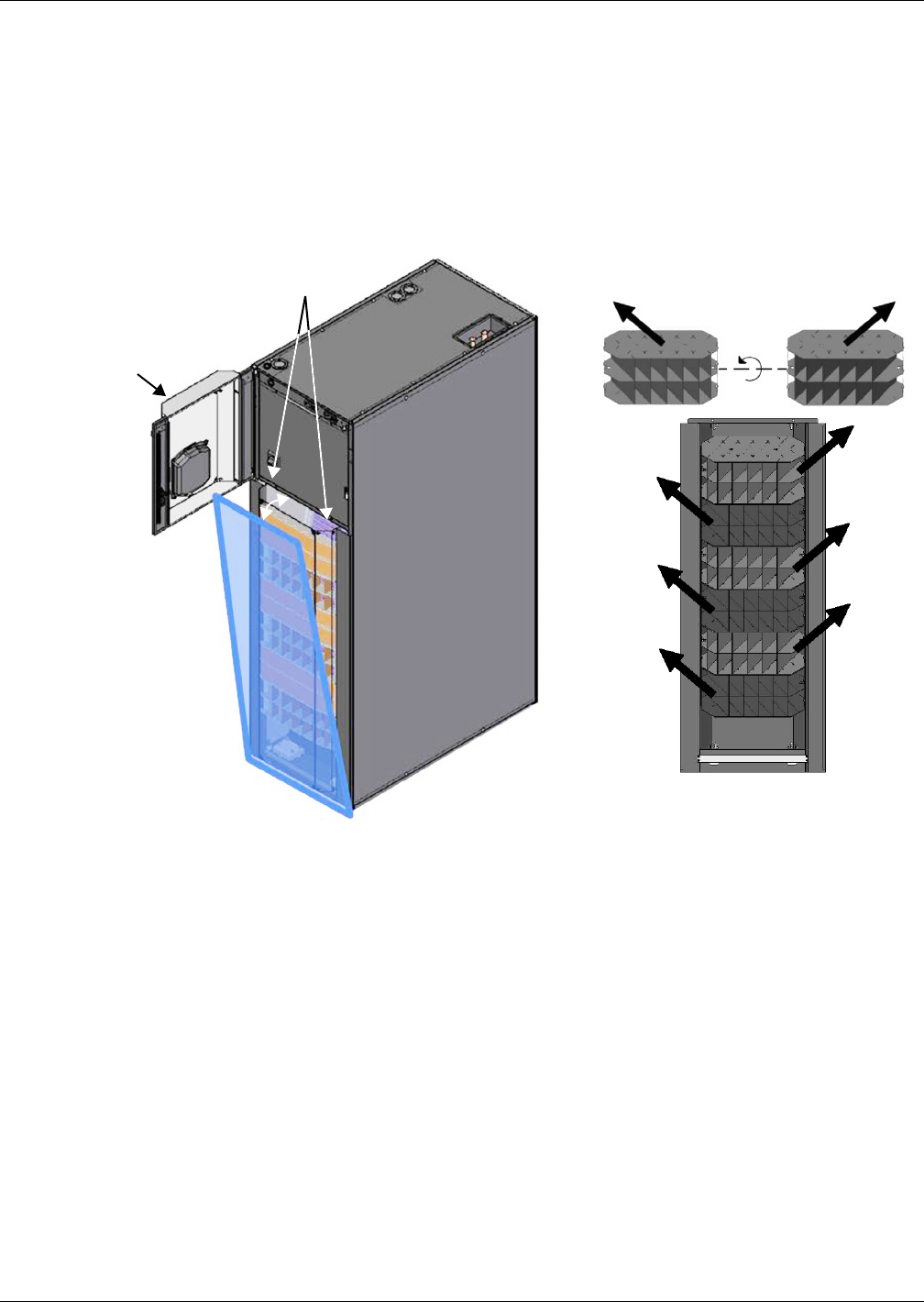
Startup
43 Liebert® CRV™
To adjust the baffles:
1. Open the door containing the Liebert iCOM® display.
2. Remove the two screws holding a baffle panel segment in place.
3. Slide out the baffle segment.
4. There is one screw on each side of the baffle, as shown in Figure 31. Remove the screws and
rotate the baffle segment around its horizontal axis to change the airflow direction.
5. Reinsert the baffle segment and reinstall the screws.
Figure 31 Adjust the baffles to ensure correct airflow direction
A blocker plate inside the display door should also be adjusted to direct air towards the racks the
Liebert CRV is intended to condition. The blocker plate can be installed on the left or right side of the
display door, or it can be removed to discharge air left and right.
1. Open Liebert
CRV Display Door
Inside view, showing
baffle removal for changing
airflow direction
2. Remove two bolts
3. Tilt and lift
baffle panel
For proper operation, the baffles
must be installed so the discharge
air points upward
DPN001863
Pg. 1, Rev. 2
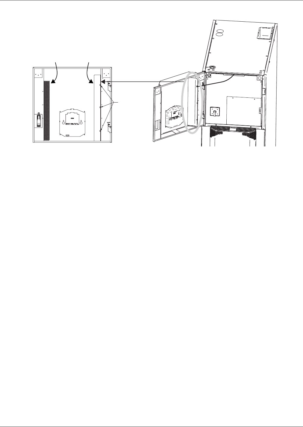
Startup
Liebert® CRV™44
Figure 32 Adjust air-blocking plate
Instructions to adjust the air blocker:
1. Remove the three screws that attach the blocker plate to the display door.
2. Reattach the blocker plate to the other side of the display door or remove entirely.
9.5 Remote Rack Sensor Wiring
The Liebert CRV is capable of supporting up to ten (10) 2T remote rack temperature sensor housings.
It is recommended that one (1) 2T housing be attached to each rack the Liebert CRV is intended to
cool. The sensors provide feedback directly to the cooling unit to improve efficiency and performance.
Rack sensors help combat cooling problems related to recirculation air, uneven rack loading and air
distribution. The 2T rack sensors are intended for cold aisle use only.
While installing the rack sensors is optional, Emerson recommends that they be installed.
Installations with multiple Liebert CRV cooling units should be connected in a Unit-to-Unit (U2U)
Ethernet network to leverage all of the Liebert iCOM® control benefits, see 11.3 Wiring a Liebert
iCOM® U2U Network.
A sensor network can be extended at any time by connecting additional 2T sensors to the last 2T
sensor on the network. Sensors connect in a daisy chain fashion back to the cooling unit; individual
wires
from each sensor to the cooling unit are avoided.
There are two steps to setting up a remote rack sensor:
• The DIP switches of the remote rack sensor must be configured to have a unique ID
• The Liebert iCOM control must be set to use the remote rack sensor as either a controlling sensor
or as a reference sensor.
Perforated Supply
Air Opening
Air Blocker Installed
Over Perforation
Attachment
Screws
FRONT VIEW
DPN001863
Pg. 2, Rev. 2
INSIDE DISPLAY DOOR
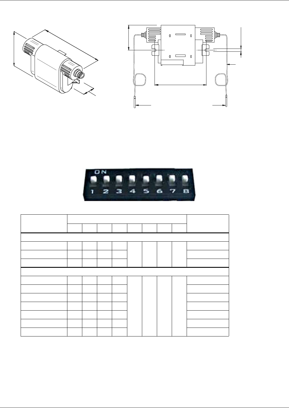
Startup
45 Liebert® CRV™
Figure 33 Figure 2T rack sensor
9.5.1 DIP Switch Settings
Three 2T sensor housings are included with each Liebert CRV. The DIP switches in these sensors
have been preset at the factory. It is recommended that you confirm that the DIP switches have been
set correctly using the below table. Any additional 2T sensor housings will need their dip switches set
per the below table. If the dip switches are not set correctly, the control will not operate properly.
Figure 34 DIP switches in 2T sensors
Table 21 DIP switch settings
2T Rack Sensor
DIP Switch Position Factory-Set
to Terminated12345678
Included with Liebert CRV
Sensor # 1 Off Off ON Off
ON off off off
—
Sensor # 2 ON Off ON Off —
Sensor # 3 Off ON ON Off Yes
Optional 2T Rack Sensors
Sensor # 4 ON ON ON Off
ON off off off
—
Sensor # 5 Off Off Off ON —
Sensor # 6 ON Off Off ON —
Sensor # 7 Off ON Off ON —
Sensor # 8 On ON Off ON —
Sensor # 9 Off Off ON ON —
Sensor # 10 ON Off ON ON —
Each temperature
probe wire is 1830mm
(6 feet) long
Temperature sensing probe
2T Sensor
Back
Front View
Source DPN001983 rev0
86
(3-3/8")
41
(1-5/8")
4.5
(3/16")
67 (2-5/8")
Max. depth
41 (1-5/8")
112 (4-7/16")
Switch Up = ON
Switch Down = OFF
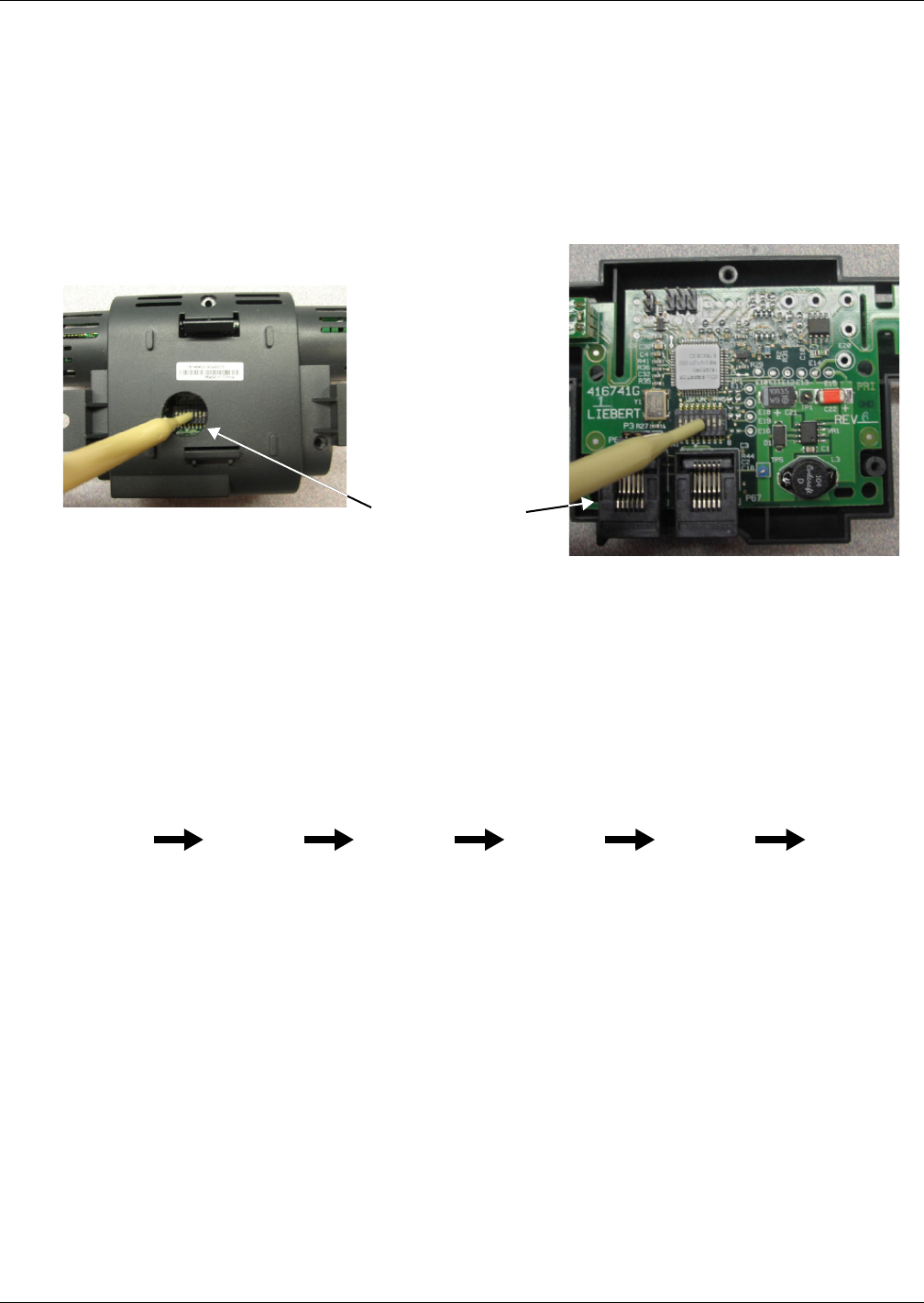
Startup
Liebert® CRV™46
9.5.2 Set 2T Rack Sensor Identities—DIP Switch settings
1. Confirm the DIP switches are set correctly for 2T sensors numbered 1, 2 and 3.
2. If additional sensors are to be connected to a cooling unit:
a. Apply numbered stickers to the sensor housings, corresponding to sensor chain position.
b. Based on the sensor number, use the included DIP switch tool to set the DIP switches
according to the table above. If you are having difficulty setting switches through the opening
in the housing or if the hole is not present, you may open the case by removing the three
Phillips-head screws. Reassemble housing once complete.
Figure 35 Setting 2T Sensor DIP Switches
Note: Use included DIP switch tool (or similar tool). DO NOT insert any metal object into the sensor
case.
9.5.3 Terminating the Last 2T Sensor on a Network
The last 2T sensor on the network, which can be identified by only having one CAN cable plugged into
it, needs to be “Terminated”. All other 2T sensors on the network need to remain “Un-terminated”.
Sensor #3 is setup as “Terminated” when it leaves the factory. As long as Sensor #3 is the last sensor
on the network, none of the other termination jumpers in the other sensors need to be adjusted.
Note: The sensors do not need to be connected in numerical order.
For example, if five sensors are purchased, they can be connected in the following pattern:
Note: In the above example, if additional sensors are added at a later time to extend the existing
sensor network, Sensor #3 will have to be “Un-terminated”. The additional sensors can then be
connected, and the new last sensor on the network will have to be “Terminated”.
• the last sensor in the new network must be terminated.
To terminate a 2T sensor:
1. Open the sensor’s case by removing the three screws that hold it together.
2. Pull the black jumper off the circuit board from Pins 1 and 2 (see Figure 36).
3. Install the jumper on Pins 2 and 3.
4. Reassemble the sensor housing.
Non-conductive
DIP switch tool
2T sensor housing DIP switch hole
2T sensor housing case opened
CRV Cooling Unit Sensor #5 Sensor #2 Sensor #4 Sensor #1 Terminated
Sensor #3
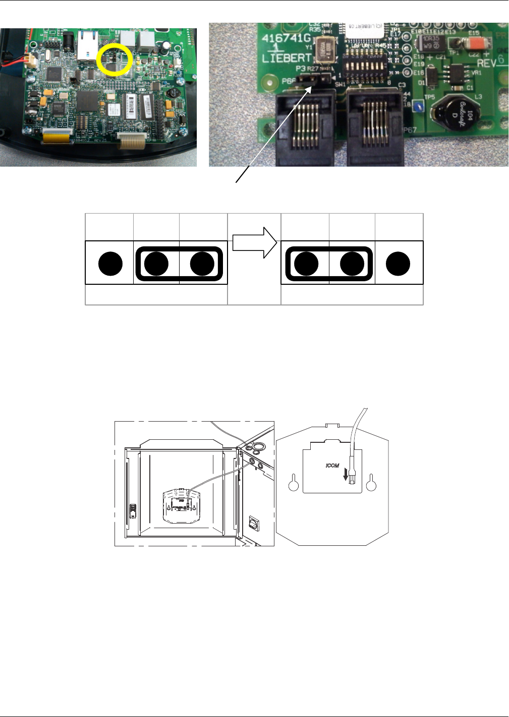
Startup
47 Liebert® CRV™
Figure 36 Termination jumper setting
9.5.4 Route the CAN bus wire into the cooling unit
The CAN bus sensors connect to the open CAN port on the back of the unit display panel. The Display
comes “Terminated” from the factory and will have to be “Un-terminated’ to allow for additional
sensors to be added. See photo above for termination jumper location for front panel display and
sensor boards. Note that connecting the CAN bus sensors will require entering the High Voltage
electrical compartment of the Liebert CRV. If you are not comfortable with the installation procedure,
it is recommended that you hire a certified electrician.
Connect the 10ft CAN wire to the open CAN bus port on the rear of the iCOM graphic display.
Ensure there is enough slack in the wire to allow the door to open and close freely, but not too much
slack to bind or pinch when the door is shut. It is recommended that a cable tie is used to secure the
wiring.
Connect the other end of the 10ft CAN cable to the nearest 2T rack sensor. Use additional CAN cables
to connect the remaining 2T rack sensors to each other. The order in which the 2T sensors are
attached does not matter; however, be sure that the last sensor connected is the one set to
“terminated”. As a best practice, avoid using excessive lengths of cable between sensors.
Unterminated Terminated
321 321
Termination Jumper
in the Terminated Position
Circuit board inside display housing Circuit board inside 2T sensor housing
Rear of Large Graphic Display
Source DPN001983 Rev. 0
Inside of Display Door
CAN CAN
SW/U2U12VDC PWR
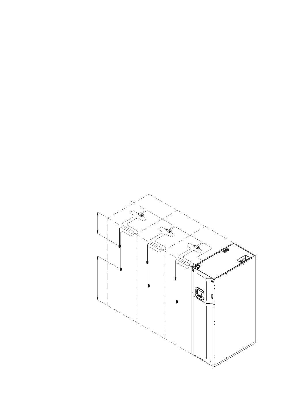
Startup
Liebert® CRV™48
9.5.5 Installing 2T sensors on racks
Both temperature sensors attached to a 2T sensor housing are to be installed on 1 rack. The sensor
can be attached to the inside or outside of the rack's front door.
• One temperature sensor is to be attached near the top of the rack’s front door by using a cable tie
to secure the wire to the perforation (approx. 12" [305mm] from the top). Do not wrap a cable tie
around the actual sensor on the end of the wire. This sensor will monitor for hot air wrapping over
the top of the rack from the hot aisle.
• The other temperature sensor is to be attached to the rack's front door, centered in front of the
heat generating equipment that will be drawing in air.
• If the rack is completely filled with equipment, locate the sensor in the middle of the door,
width and height.
• If the rack is partially filled with equipment, locate the sensor in the center of the equipment
on the front door.
•Do NOT
• Install a sensor in the hot aisle
• Leave a sensor coiled on top of or inside the rack.
• With the temperature sensors in place, neatly route the wires up the rack door and into the rack
using the supplied cable ties. Be sure to leave an appropriate amount of slack in the cable to allow
the rack door to open and close without binding or pinching the wires.
• Affix the 2T sensor housing to the rack using the supplied hook-and-loop fastener. It is recom-
mended that the housing be installed in an easily accessible space with the sensor number label
visible in case the housing needs accessed at a later time.
• Repeat this process until all sensors have been installed.
Figure 37 2T rack sensors installed on neighboring racks
2T SENSOR CHAIN
Approx. center
of rack/in front
of IT equipment.
Install temperature sensors on the
perforated portion of the rack door
using the supplied zip-ties.
Ensure that the doors swing freely without
binding cables.
305
(12in)
Source DPN001983 rev0
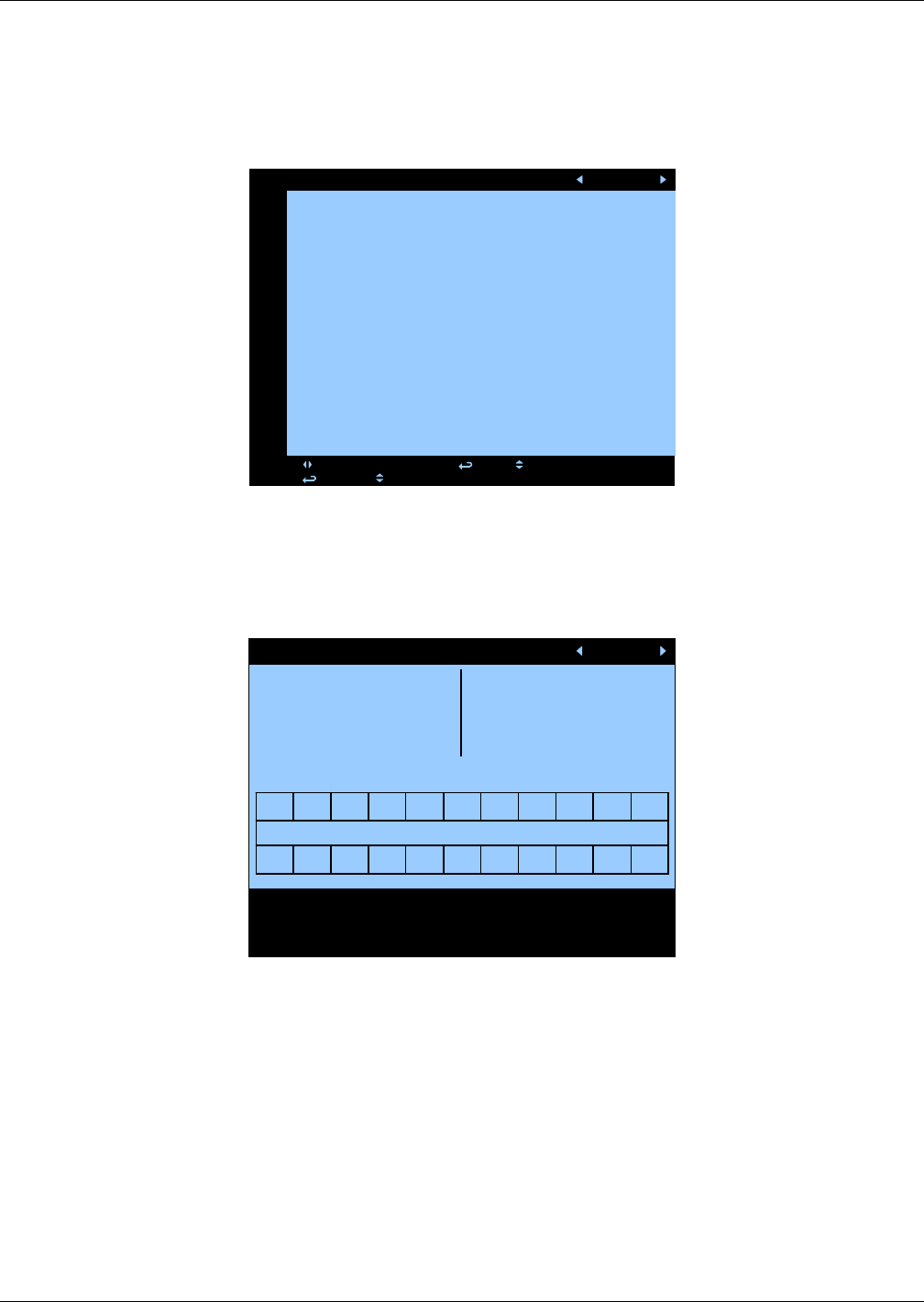
Startup
49 Liebert® CRV™
Located in the Service / Rack Setup Menu of the Liebert iCOM® display, the sensors can be set up to
either display or control temperature, give them a rack name and draw a rack layout that can be
viewed in the User menu.
9.5.6 Remote Rack Sensor Operation and Rack View Setup
Figure 38 Rack setup screen, page 1 of 3
Once the remote rack sensors have been configured and plugged into the CAN bus network, the
control can be configured to use the sensor for either control or reference. If the sensor is set to
“Disable,” it will be ignored. The sensor node number corresponds to the DIP switch assignment of the
sensor.
Figure 39 Rack setup screen, page 2 of 3
Once a sensor has been assigned to either control or display its temperature data a virtual position
can then be assigned to the sensor. This screen configures the Rack View layout in the User menu.
This step is not required for the sensor to operate but does provide a logical position in the row for
quickly referencing affected racks near the Liebert CRV. To set up navigate using the arrow and enter
keys to highlight the Assign Sensors number range. Once the range is selected then press the enter
key to move to the rack location blocks at the bottom of the screen. The Up and Down arrow keys can
be used to select the sensor node number. For the Liebert CRV select “CRV.”
Rack Setup (page 1 of 3) UNIT 01
S901 PASSWORD (act. Level 0) ????
S902 Remote Sensor Node 01 Control
S903 Remote Sensor Node 02 Reference
S904 Remote Sensor Node 03 Disable
S905 Remote Sensor Node 04 Control
S906 Remote Sensor Node 05 Reference
S907 Remote Sensor Node 06 Disable
S908 Remote Sensor Node 07 Control
S909 Remote Sensor Node 08 Reference
S910 Remote Sensor Node 09 Disable
S911 Remote Sensor Node 10 Control
press: for next/prev unit; and to select parameter
press: , then to change parameter
Rack Setup (page 2 of 3)
Liebert CRV = CRV
No Sensors = NoS
No rack = [blank ]
Sensor Note = 01-10
Assign Names : 01-06
07-12
13-18
19-22
02 00 00 00000001 03 04 05 06
DC01 DC03
DD02
DC05 DC07
DD04 CRV
DC09 DC11
00 00 00 00080700 CRV 00 00 00
Cold Aisle
Use the navigation keys to move from rack to rack,
Enter to select a rack, and up- or down keys to
scroll through options.
UNIT 01
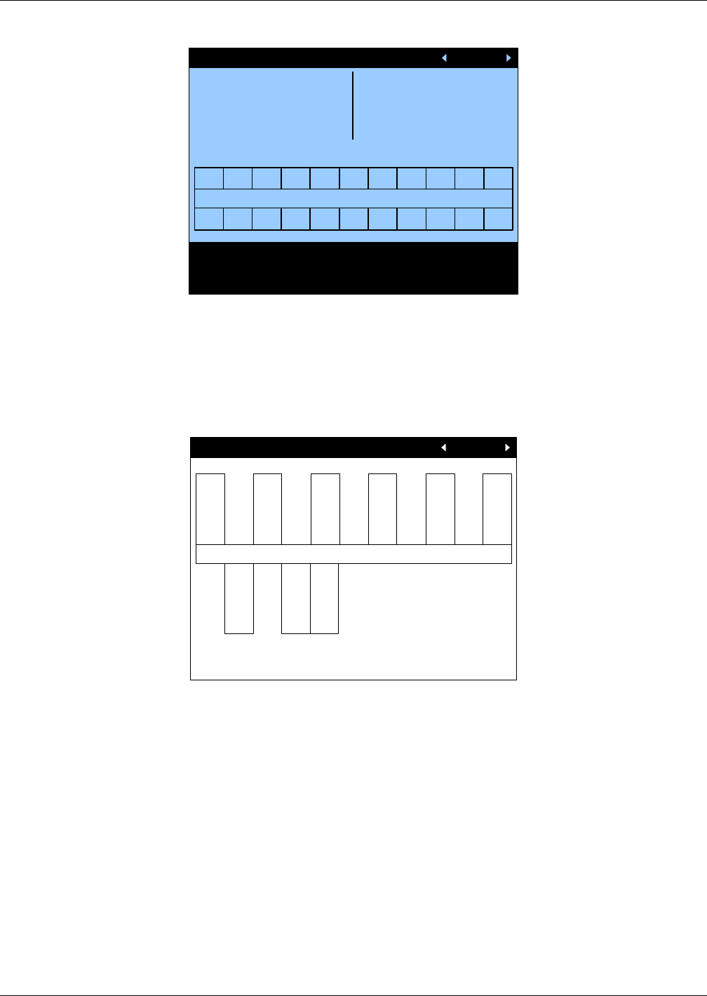
Startup
Liebert® CRV™50
Figure 40 Rack setup screen, page 3 of 3
Once a sensor has been assigned to either control or display its temperature data, a custom label can
be assigned to the sensor. This step is not required for the sensor to operate but does provide a logical
name for identification. Navigate using the arrow and enter keys to highlight the Assign Names
number range. Once the range is selected then press the Enter key to move to the rack location blocks
at the bottom of the screen. The Up and Down arrow keys can be used to select any alpha or numeric
value up to four positions.
Figure 41 Rack overview screen
If the Rack Setup menus are configured in the Service menu to locate and label the remote rack
sensors, then the Rack View in the User menu should look similar to the screen above. This screen
will show the node number at the top of each block, the label and the actual temperature that each
sensor is currently measuring.
Rack Setup (page 3 of 3)
Liebert CRV = CRV
No Sensors = NoS
No rack = [blank]
Sensor Note = 01-10
Assign Names: 01-06
07-12
13-18
19-22
02 00 00 00000001 03 04 05 06
DC01 DC03
DD02
DC05 DC07
DD04 CRV
DC09 DC11
00 00 00 00080700 CRV000000
Cold Aisle
Use the navigation keys to move from rack to rack,
Enter to select a rack, and up- or down keys to
scroll through options.
UNIT 01
Rack Overview (page 1 of 1) UNIT 01
Cold Aisle
RAC1
71.4
EMAL
72.8
BLAD
69.4
RAC4
70.1
DC07
74.5
RAC6
71.0
72.4
06KW
69.3
CRV1
70.8
DISC
All temperatures shown in °F
01 02 03 04 05 06
07 08 CRV
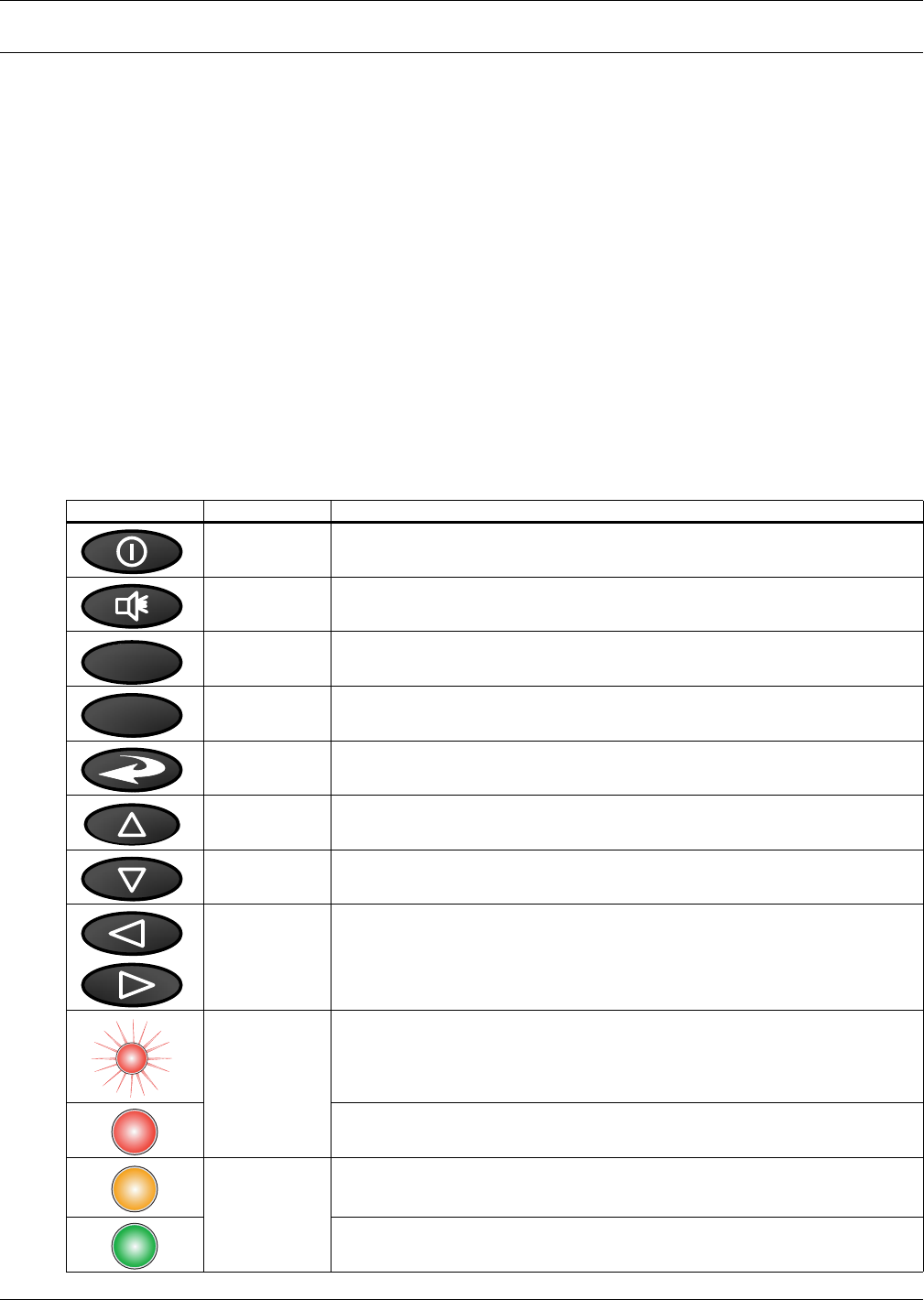
Liebert iCOM® Control
51 Liebert® CRV™
10.0 LIEBERT ICOM® CONTROL
The Liebert CRV is equipped with the most advanced Liebert iCOM control system. The large Liebert
iCOM display is standard on the Liebert CRV.
Each Liebert CRV contains a return air temperature and humidity sensor, supply air temperature
sensor and three remote rack sensors. Up to an additional 7 remote rack sensors can be added to the
sensor network. Each rack sensor takes two temperature readings and reports either the average or
the maximum temperature of the two sensors.
The 2T rack temperature sensors provide feedback to the cooling unit about the condition of the air
entering the server racks. This information allows the Liebert CRV to ensure it is providing just
enough cold air to each rack, virtually eliminating hot spots. Overcooling and excessive airflow are
avoided, greatly reducing unnecessary energy consumption.
Each Liebert CRV includes three 2T rack temperature sensors to monitor three racks. A total of ten
2T temperature sensors can be connected to each cooling unit to monitor every rack a Liebert CRV is
protecting. When multiple cooling units are connected in a Unit-to-Unit iCOM control network, all
sensor data is shared to optimize their performance as a system.
2T rack sensors can also be initially installed on empty racks reserved for future growth with the
control set to ignore these sensor readings. The extra 2T temperature sensor readings can also be
displayed on the local display and reported remotely for monitoring purposes only; not impacting unit
operation. This function provides users with a built-in mini-monitoring system.
Table 22 Keyboard icons and functions
Icon Key Name Function
On/Off Key Controls the operational state of the cooling unit.
Alarm Key Silences an alarm.
Help Key Accesses integrated Help menus.
ESCape Key Returns to the previous display view.
Enter Key Confirms all selections and selects icons or text.
Increase Key
(Up Arrow) Moves upward in a menu or increases the value of a selected parameter.
Decrease Key
(Down Arrow) Moves downward in a menu or reduces the value of a selected parameter.
Left and Right
Arrow Keys Navigates through text and sections of the display.
Upper LED
Blinking Red—Active, unacknowledged alarm exists
Solid Red—Active, acknowledged alarm exists
Lower LED
Amber—Power is available to the unit; unit is NOT operating
Green—Unit is operating with no alarms
?
ESC
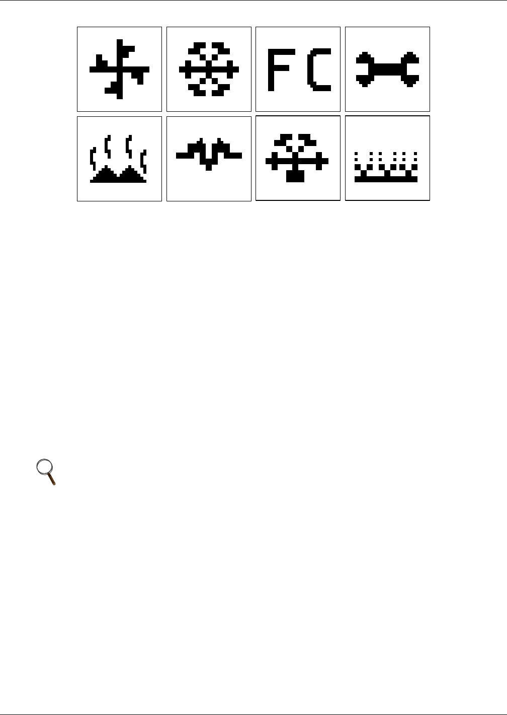
Liebert iCOM® Control
Liebert® CRV™52
Figure 42 Liebert iCOM® default screen symbols
10.1 Navigating Through the Liebert iCOM Menus
Liebert iCOM shows icons and text for monitoring and controlling your Liebert cooling units or
network of cooling units. The number of icons and amount of text shown depends on the display size.
10.1.1 Control Interface
When the buttons on the Liebert iCOM control have not been pressed for a short period, the display
backlight turns off. Pressing any key will turn the backlight on (wake up the screen) and display the
Status menu of the last cooling unit viewed. The Status menu will show the cooling unit’s operational
mode(s), return air temperature and humidity readings, temperature and humidity setpoints and any
active alarm conditions.
If the cooling unit has a large display and is not on a network, whether it is networked or stand-alone,
the Status menu will display only that cooling unit’s information. Any large display that is connected
to a network can be used to view any cooling unit on the network or show an average view of the
entire system of cooling units.
The Liebert iCOM control has three main menus: User, Service and Advanced.
The User menu contains the most frequently used features, settings and status information. The
Service menu contains settings and features used to set up unit communications and for unit
maintenance. The Advanced menu contains settings used to set up the unit at the factory.
10.1.2 Accessing Submenus
To access the User, Service or Advanced menu, press the Enter or down arrow key while viewing the
Status menu of the unit you wish to access. The User menu will be displayed first. To view the Service
or Advanced menus, press the right arrow key.
Accessing Submenus on Large Displays
While viewing the menu you wish to access (User, Service or Advanced), press the enter key to
highlight the first icon. Use the arrow keys to navigate through the icons. With the desired icon
highlighted, press the enter key to enter that submenu. Once in a Submenu, a list of parameters will
be displayed.
The up and down arrow keys may be used to scroll through the parameters page-by-page if the
submenu has multiple pages. To scroll item-by-item, press the Enter key and then use the up and
down arrow keys. Using the right or left arrow keys on large displays attached to a network will
NOTE
Menu settings may be viewed without a password, but changing settings requires a password.
If a password is required, Liebert iCOM shows a prompt to enter the password. The password
for the User menu is 1490. The password for Service menu is 5010. For details on entering a
password, see Entering a Password on page 53
fan cooling maintenance
hot water electric heat dehumidification humidification
freecooling
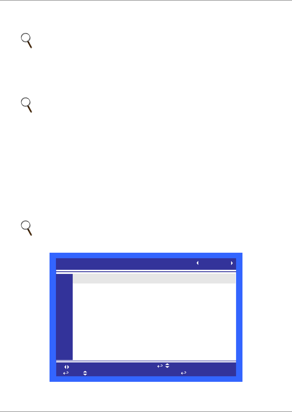
Liebert iCOM® Control
53 Liebert® CRV™
change the unit being viewed. Pressing the ESC key will go back a level. Figures 44 and 45 show the
Liebert iCOM® control menus for a stand-alone large display and for a networked large display,
respectively.
10.1.3 Entering a Password
To change the value of a parameter in a menu, you must first enter the password for that menu. Each
menu—User, Service and Advanced—has a unique password to prevent unauthorized changes.
The User menu password is 1490; the Service menu password is 5010.
To enter a password:
1. Navigate to the menu that contains the parameter to be changed.
2. Select Password in the submenu by pressing the Enter key
3. Press the Enter key to move your cursor to the right side of the screen to select the question
marks.
4. Use the arrow keys to enter the numeral for the password’s first digit (the up arrow key moves
from 1 to the next digit).
5. Use the right arrow key to move to the next question mark and repeat Step 4 to enter all digits in
the password.
6. After entering the password, press enter.
If the password is correct, the Actual Level shown to the right of Password will change
from 0 to 1 or 2. The menu will remain locked if the password was incorrect.
Figure 43 Entering a password
NOTE
Settings are readable without a password, but changing settings requires a password.
NOTE
Entering the Service menu password permits access to both the User and Service menus;
changes can then be made to parameters in either level.
NOTE
Returning to the Status menu will require re-entering a password to make changes.
SETPOINTS
to change parameter to confirm
to select parameter
for next/previous unit
then
PASSWORD (Actual Level 0)
Temperature Setpoint
Humidity Setpoint
Humidity Control Type
Supply Sensor
Supply Setpoint
Backup Temperature Setpoint
????
73°F
50.0%
Relative
Control
50°F
73°F
UNIT 01
U101
U102
U103
U104
U105
U106
U107
U108
U109
U110
U111
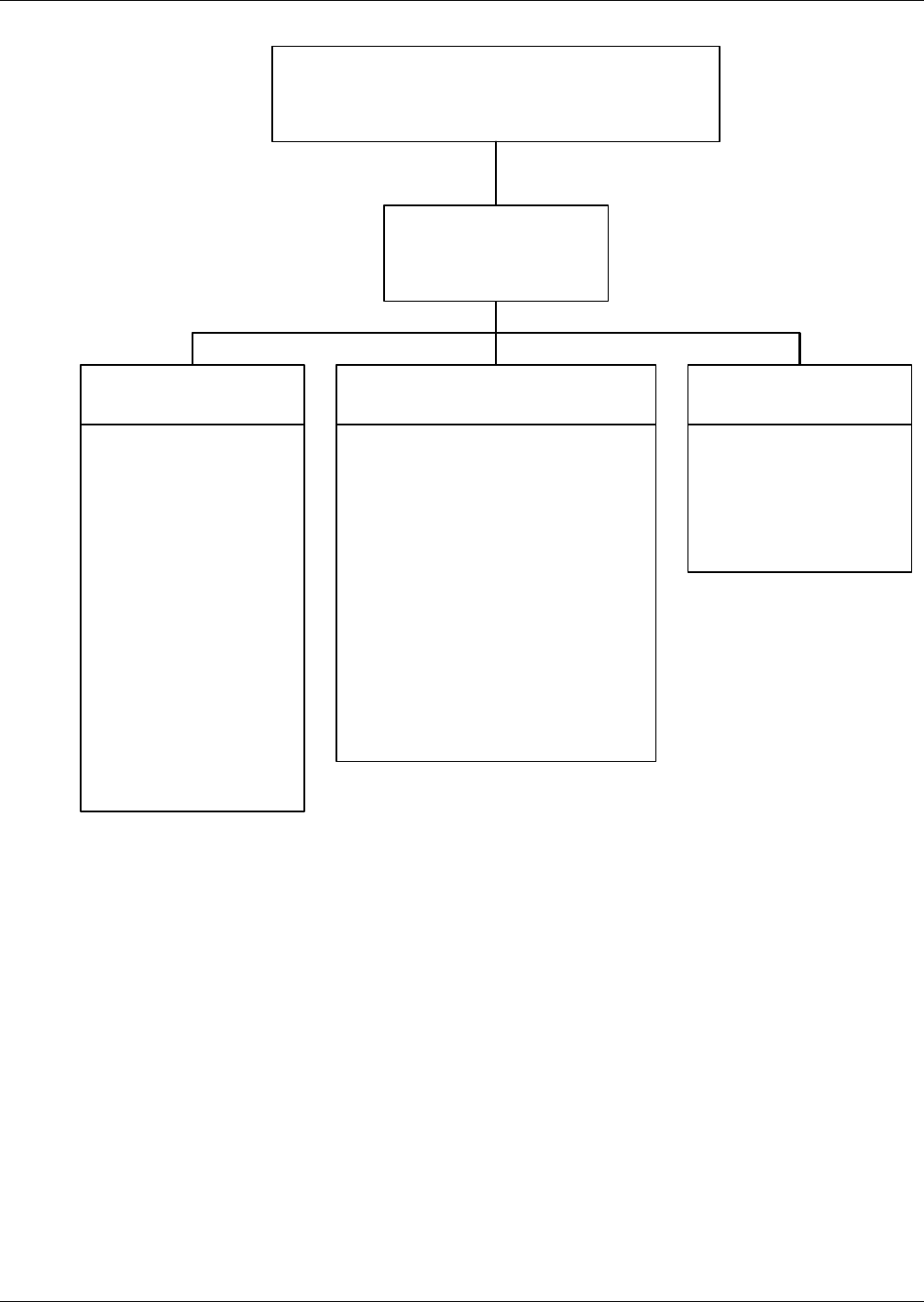
Liebert iCOM® Control
Liebert® CRV™54
Figure 44 Menu tree—Large display, stand-alone
Status Menu – System View
Status Menu
Unit 1 View
User Menu
Unit 1
Password
Setpoints
Spare Part List
Event Log
Graphics
View Network
Set Alarms
Sensor Data
Active Alarms
Display Setup
Total Run Hours
Sleep Mode
iCOM-DO
Service Contact Info
Service Menu
Unit 1
Password
Setpoints
Unit Diary
Standby Settings/Lead-Lag
Maintenance/Wellness Settings
Diagnostics / Service Mode
Set Alarms
Sensor Calibration/Setup
System/Network Setup
Options Setup
iCOM-DO
Service Contact Info
Advanced Menu
Unit 1
Password
Factory Settings
Compressor Info
Access Passwords
Unit 1 will be displayed
in the top left corner of
the screen.
Liebert iCOM® Control
55 Liebert® CRV™
10.1.4 Viewing Multiple Units with a Networked Large Display
When you first wake up the control, press the ESC key to return to the System view Status menu.
This view shows an average of all the units on the network and any alarms present. To view a specific
unit on the network, press either the enter key or down arrow key. When you do this, you will see the
word System in the top left of the screen change to a unit number. Using the left and right arrow keys
you can toggle through the various units on the network. To go back to the System view, or back one
level from any menu in the control, press the ESC key.
Figure 45 Menu tree—Large display, networked
Status Menu – System View
(Networked Large Display Only)
Status Menu
Unit 1 View
Status Menu
Unit 2, 3, 4...
User Menu
Unit #
Password
Setpoints
Spare Part List
Event Log
Graphics
View Network
Set Alarms
Sensor Data
Active Alarms
Display Setup
Total Run Hours
Sleep Mode
iCOM-DO
Service Contact Info
Service Menu
Unit #
Password
Setpoints
Unit Diary
Standby Settings/Lead-Lag
Maintenance/Wellness Settings
Diagnostics / Service Mode
Set Alarms
Sensor Calibration/Setup
System/Network Setup
Options Setup
iCOM-DO
Service Contact Info
Advanced Menu
Unit #
Password
Factory Settings
Compressor Info
Access Passwords
Unit # or System will be
displayed in the top left
corner of the screen.
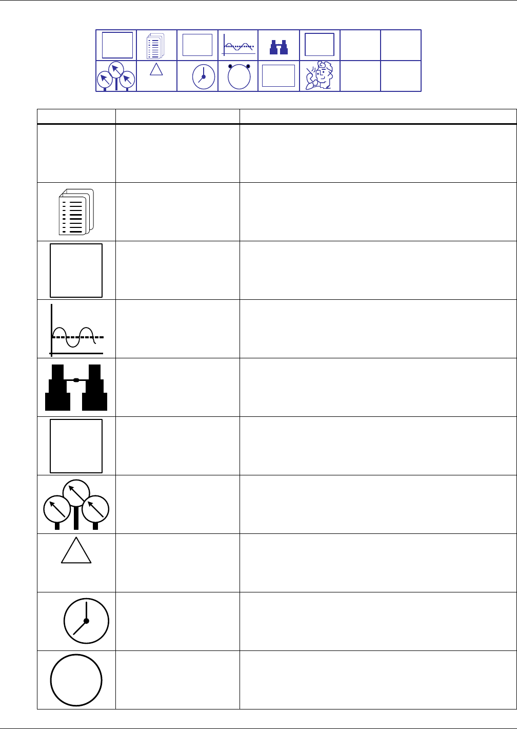
Liebert iCOM® Control
Liebert® CRV™56
Figure 46 User menu icons
Table 23 User menu icons
Icon Name Description
Setpoints View and change temperature and humidity setpoints
Spare Part List Displays the various part numbers of the components/parts
in the cooling unit
Event Log Contains last 400 events
Graphics Displays temperature and humidity graphs
View Network Shows status of all connected units
Set Alarms Allows enable, disable and settings for alarms
Sensor Data Shows readings of standard and optional sensors
Active Alarms Allows the user to view all current active alarms
Display Setup Change settings for display: language, time, simple or graphic view
Total Run Hours Records the run time of all components and allows setting
of limits on run time
EVENT
LOG
°C / °F
% RH
SET
SET
12
39
6
SET
ALARMS
!
ACTIVE
ALARMS
1234
h
RACK
VIEW
User Menu
password: 1490
°C / °F
% RH
SET
EVENT
LOG
SET
ALARMS
!
ACTIVE
ALARMS
1 2
39
6
SET
1234h
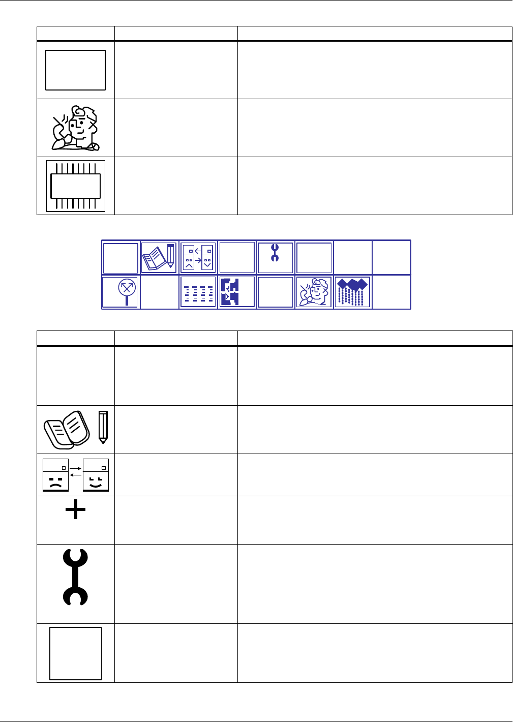
Liebert iCOM® Control
57 Liebert® CRV™
Figure 47 Service menu icons
Rack View Allows viewing data, collected by sensors, about rack status
Service Contact Info Contains key contact information for local service, including names
and phone numbers
iCOM-DO Change settings for Liebert iCOM® Discrete Output card
Table 24 Service menu icons
Icon Name Description
Setpoints To view and change temperature and humidity setpoints
Unit Diary Shows all entered program changes and maintenance performed
on the unit
Standby Settings/ Lead-Lag Allows lead/lag setup when multiple units are connected
Maintenance/
Wellness Settings
Allows setting maintenance interval reminder, maintenance
message, number of unit starts and stops and time since last
maintenance
Diagnostics/
Service Mode
Allows troubleshooting, manual mode, read analog and digital
inputs
Set Alarms Allows enable, disable and settings for alarms
Table 23 User menu icons (continued)
Icon Name Description
RACK
VIEW
DO
+
WELLNESS
SET
ALARMS
SERVICE
+/-
NETWORK SET
UP RACK
SETUP
°C / °F
% RH
SET
Service Menu
password: 5010
°C / °F
% RH
SET
WELLNESS
SERVICE
SET
ALARMS
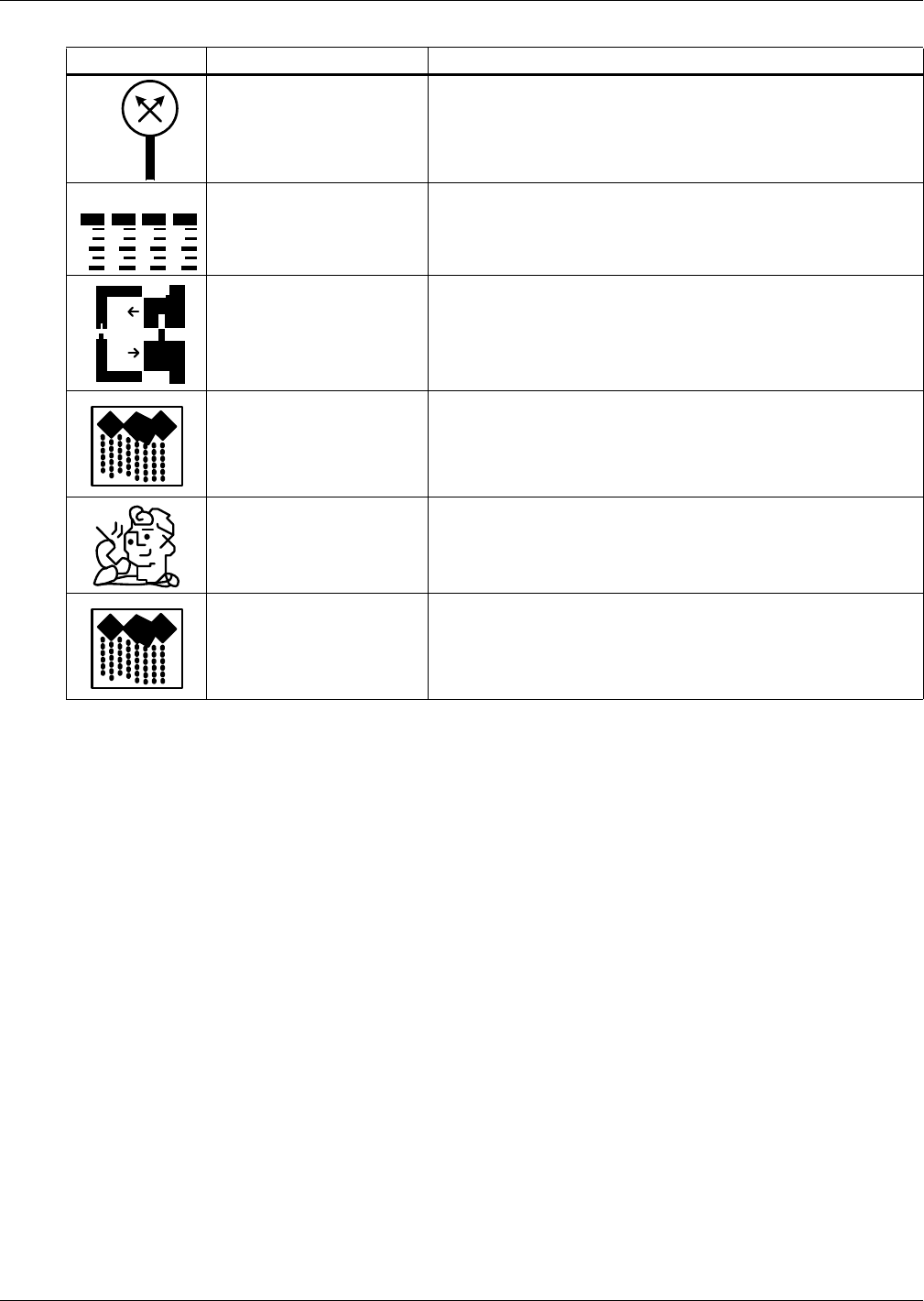
Liebert iCOM® Control
Liebert® CRV™58
Sensor Calibration/Setup Allows calibration of sensors
System/Network Setup Allows setup and U2U communication for multiple units
Options Setup Allows setup of component operation
Rack Setup Label racks, establish settings for sensors
Service Contact Info Contains key contact information for local service, including
names and phone numbers
Humidifier Settings Change Humidifier settings
Table 24 Service menu icons (continued)
Icon Name Description
+ / -
NETWORK
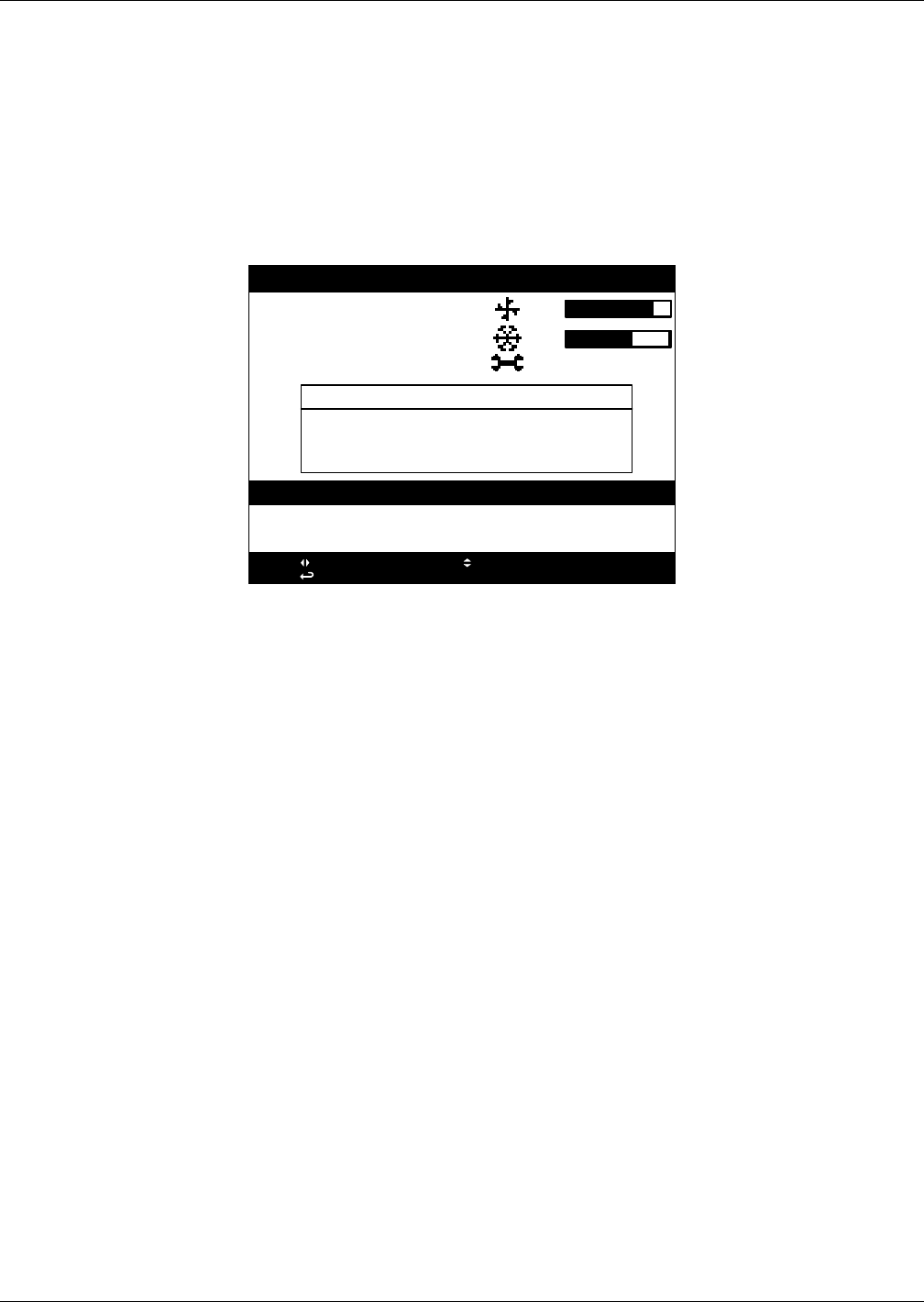
Liebert iCOM® Control
59 Liebert® CRV™
10.2 Liebert iCOM® Display Readout
The Liebert iCOM controller for the Liebert CRV supports multiple main screen layouts. The screens
are a graphical representation of the Liebert CRV, selectable to show unit operation with or without
rack sensors, unit operation with a rack sensor summary, historical temperature and humidity
trending or trending the screens used on other Liebert products. Unlike other Liebert cooling
products, the Liebert CRV display will always revert to the Unit Screen instead of the System Screen.
The following screens are user preference. The remote rack sensor screens should be used only when
remote rack sensors are connected.
Figure 48 Liebert CRV system screen
The System screen can be accessed by pressing the Up arrow key when the Unit screen is displayed.
The System screen shows the fan speed and cooling capacity averages of all connected units. The
Supply, Return and Remote Rack sensors of all connected units are also displayed showing the
average, maximum and minimum of all connected sensors.
SYSTEM
Liebert
CRV
Average
Average
Next
89%
67%
04/2011
System Supply Return Remote
Average: 67°F 96°F 71°F
Maximum: 72°F 102°F 78°F
Minimum: 62°F 87°F 69°F
28.02.2011 15:03 SYSTEM ON
28.02.2011 14:07 (01) UNIT ON
28.02.2011 14:07 (01) POWER ON
press: for next/prev unit; for unit/system view
press: for menu; ESC for prev screen; ? for help
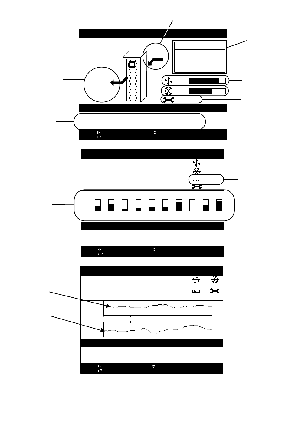
Liebert iCOM® Control
Liebert® CRV™60
Figure 49 Liebert iCOM® menu components for Liebert CRV
UNIT 1
Liebert
CRV
Rack Inlet Temp
Average : 71°F
Maximum: 73°F
Minimum: 69°F
28.02.2011 15:03 UNIT ON
28.02.2011 14:07 (01) UNIT ON
28.02.2011 14:07 (01) POWER ON
press: for next/prev unit; for unit/system view
press: for menu; ESC for prev screen; ? for help
89%
67%
04/2011
98°F
20%RH
69
51
°F
%RH
SYSTEM
Liebert
CRV
28.02.2011 15:03 UNIT ON
28.02.2011 14:07 (01) UNIT ON
28.02.2011 14:07 (01) POWER ON
press: for next/prev unit; for unit/system view
press: for menu; ESC for prev screen; ? for help
89%
67%
0%
04/2011
°F 71.4 72.8 69.4 70.1 70.8 71.0 74.577.772.4 76.8
RAC1 EMAL BLAD RAC4 DISC RAC6 06KWDC08DC07 DC10
69.3
Front
Supply
°F
SYSTEM
Liebert
CRV
28.02.2011 15:03 UNIT ON
28.02.2011 14:07 (01) UNIT ON
28.02.2011 14:07 (01) POWER ON
press: for next/prev unit; for unit/system view
press: for menu; ESC for prev screen; ? for help
69.3
Front
Supply
°F
89%
0%
67%
04/11
16d 12d 8d 4d
+5
69°
-5
+10
51%
-10
Av. Rack
Temp
Supply
Hum.
18:55
Supply Temperature
and Humidity
Last Two Events,
Warnings or Alarms
Individual Rack
Sensor Temperatures
The rack graph is empty
at 68°F (20°C) and full at
77°F (25°C).
Historical Supply
Air Temperature
Graph
Historical Supply
Air Humidity
Graph
Fan Speed
Return Temperature
and Humidity
Cooling Capacity
Next recommended
maintenance
Summary of Rack
Sensor Readings
Humidification
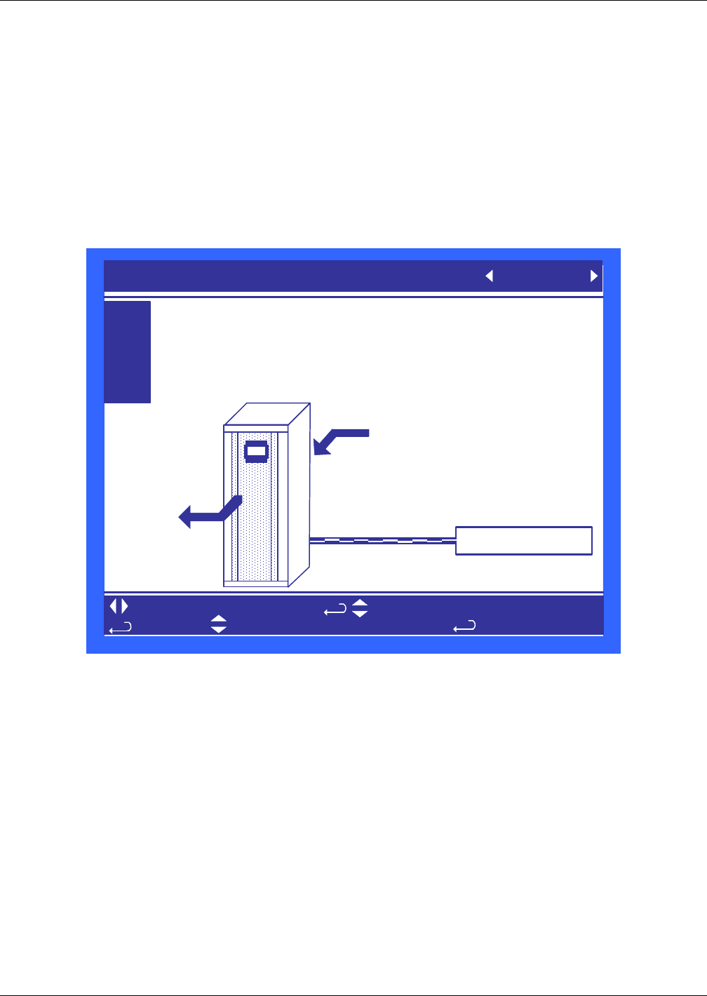
Liebert iCOM® Control
61 Liebert® CRV™
10.3 Liebert iCOM® Control Setup
The Liebert iCOM on the Liebert CRV leaves the factory with the fan speed and cooling capacity
controlled by the supply air sensor. This control mode is extremely robust and will ensure that you
are delivering precise cooling to the cold aisle. To unlock the full capability of the Liebert CRV, the
remote rack sensors should be installed, which will allow the fan speed and the cooling capacity to be
“de-coupled.” This means that the fan speed can now be controlled independently of the cooling
capacity. In this advanced configuration, the Liebert CRV can control the discharge temperature of
the unit by modulating cooling capacity based on the supply sensor and use the remote rack sensors
to ensure that the cool air is being delivered to the inlet of the racks. Using the supply and remote
rack sensors in this de-coupled mode is the preferred method for controlling the Liebert CRV in a hot
/ cold aisle configuration. In addition to this configuration Emerson has provided additional flexibility
for other applications shown in Table 25.
Figure 50 Setpoint screen
In Figure 50, the controlling temperature sensor can be set to either Supply, Return or Remote. As
the selection is changed from one sensor to another, the setpoint is displayed next to the
corresponding sensor on the illustration, giving a visual indication of the sensor placement in
relationship to the Liebert CRV.
A password must be entered to change the setting; see 10.1.3 Entering a Password for assistance
on entering the password.
Temperature sensor settings are based on user preference. Use the settings below as a guideline.
1. Set the remote temperature setpoint to the desired server inlet temperature
2. Set the humidity setpoint to 45% with a 10 to 20% deadband.
This will control the moisture content well inside the AHSRAE standard.
3. Set the supply setpoint 5°F below the setting for the remote rack sensor.
This will serve as a starting point.
If 75°F (24°C) server entering air temperature is desired, the supply air must be colder to account for
any thermal pickup of the air as it flows to the cold aisle. If this does not achieve the cold aisle
temperature Setpoint, then set the supply sensor setpoint lower. Continue to do this until the cold
aisle temperature setpoint is achieved.
SETPOINTS UNIT 02
U101
U102
U103
U104
PASSWORD (Actual Level 0)
Controlling Sensor
Temperature Setpoint
Humidity Setpoint
????
Supply
70°F
50%
for next/previous unit
then
Supply Sensor
Return Sensor
Remote Sensor
to change parameter
70°
50%
to select parameter
to confirm

Liebert iCOM® Control
Liebert® CRV™62
The supply temperature Setpoint may require adjusting since it will be dependent on the distance of
the CRV to the server racks being cooled. This temperature will also be dependant on rack blanking
panels, server population and if containment is being used.
Table 25 shows the flexibility of the Liebert CRV and how the different sensor configurations can be
used to control the Liebert CRV fan speed and cooling capacity. The table shows the different coupled
and decoupled modes available for the Liebert CRV.
10.4 Event Log
The event log displays all events and actions that have been generated by the unit. When multiple
units are networked you will see the event log of the whole system. Each event shows the unit that
generated the alarm, time and date stamp, a description and the event type.
10.5 Spare Part List
The spare parts lists contains a detailed description and part number that can be used to order parts
for the unit. These part numbers are specific to each model and option installed on the unit.
10.6 Wellness—Next Maintenance Calculation
The next maintenance calculation, as well as the included diagnostics feature, will help keep the
cooling unit running at peak performance to ensure minimum component stress and maximum
reliability. The diagnostics will help the service engineer evaluate the unit’s operation since the last
maintenance.
10.6.1 Calculation of Next Maintenance and Diagnostics
If the unit includes any of the following components, they are included in the calculation:
•Fan(s)
• Compressor 1
• Compressor 2
• Electric Heaters
• Humidifier
For each component, the next maintenance will be calculated from the following parameters:
• Standard service interval (1, 2 or 4 times a year) (to be set)
• Working hours (counted)
• Number of starts (counted)
• Average running time (calculated)
• Optimum number of starts per hour (to be set)
• Maximum number of starts per hour (to be set)
• Maximum bonus to enlarge time to next maintenance (to be set)
• Maximum penalty to reduce time to next maintenance (to be set)
Table 25 Controlling sensor settings
Cooling Control
S103Cool / S125 Fan Supply Remote Sensor Return
Fan Control
Supply Factory Default
(Coupled) N/A N/A
Remote Sensor Recommended
(Decoupled)
X
(Coupled) N/A
Return X
(Decoupled)
X
(Decoupled)
X
(Coupled)

Liebert iCOM® Control
63 Liebert® CRV™
Calculating Unit Wellness
Liebert iCOM® keeps tabs on the condition of a cooling unit, determining its wellness and projecting
when service will be needed, for the entire unit as well as for individual components. This assists in
scheduling maintenance calls and helps pinpoint components likely to require service.
Liebert iCOM displays a graphic for needed maintenance. It begins with the standard maintenance
interval—12 months, six months or three months—and adjusts that based on its calculation of
components’ wellness.
To calculate wellness, Liebert iCOM keeps a running total of component working hours and the
number of times it has been started. Liebert iCOM relates that data to the optimum/maximum starts
per hour. Accordingly, Liebert iCOM will increase or decrease the time before the next service call will
be needed.
The more frequently a component starts, the sooner it is likely to need maintenance. If, for example, a
unit’s fan runs continuously, but it’s compressor starts and stops often, Liebert iCOM records that
and calls for maintenance based on the compressor’s wellness factor.
Alarms and warnings, such as clogged filters or high or low pressure, reduce the time till the next
maintenance to zero. If the alarm is cleared and reset, Liebert iCOM recalculates wellness. It begins
with the pre-alarm maintenance time and factors in the alarm.
Parameters for Next Maintenance Calculation
General Maintenance Settings
•Maintenance Frequency—can be set as one to 12 months or to zero, which disables mainte-
nance calculation
•Max. Bonus—increases the time to next maintenance with the set value, if all components run
optimally (number of starts, average running time)
•Max. Penalty value—decreases the time to next maintenance with the set value, if some compo-
nents run in non-optimum way (number of starts, average running time)
•Last Maintenance—date can be set from service-engineer; informational
•Service-Engineer—name of the service engineer; editable
•Reset—puts all counters of all components, such as (motor, compressors, heaters and humidifier),
at zero and starts a new maintenance calculation (reset to be done after maintenance)
Fans / Heaters / Humidifier Settings and Diagnostics
• Number of starts and Working hours are counted separately since the last maintenance. Total
working hours can be read in the standard working hours window (customer window).
• Average Working Hours is the calculation, resulting from starts and working hours.
• Starts per Day Optimum is the number of starts considered as optimum.
• Starts per Day Worst is the number of starts considered as hunting (worst case).
• Number of Alarms counts the alarms, happened between two service intervals.
• Actual Bonus is calculated from number of starts and average working time. Can be positive
(bonus) or negative (penalty). This value influences the time remaining to the next maintenance.
Compressor 1 / 2 Settings and Diagnostics
• Number of starts and Working hours are individually counted since the last maintenance. Total
working hours can be read in the standard working hours window (customer window).
• Average Working Hours is the calculation, resulting from starts and working hours.
• Starts per Day Optimum is the number of starts considered as optimum.
• Starts per Day Worst is the number of starts considered as hunting (worst case).
• Number of HP Alarms counts the high-pressure alarms, happened between 2 service intervals.
• Number of LP Alarms counts the low-pressure alarms, happened between 2 service intervals.
• Number of TH Alarms counts the thermal protection alarms, happened between 2 service inter-
vals.
• Actual Bonus is calculated from number of starts and average working time. Can be positive
(bonus) or negative (penalty). This value influences the time remaining to the next maintenance.

Liebert iCOM® Control
Liebert® CRV™64
10.7 Liebert CRV Operation—Liebert iCOM® Control
10.7.1 Cooling
The cooling control of the Liebert CRV can be managed from any of the temperature sensors. Emerson
recommends using the supply temperature sensor to control the cooling capacity of the Liebert CRV.
The supply temperature is an accurate representation of the actual heat rejection the Liebert CRV
needs to perform at an optimal level. A chilled water version of the Liebert CRV will modulate the
cooling capacity from 0% - 100% and the DX version of the Liebert CRV will modulate the cooling
capacity of the unit from 20% -100% compressor capacity.
To avoid short-cycling the compressor during room heat load changes, the Liebert CRV will not
deactivate the compressor until the air temperature is below 150% of temperature setpoint when in
Remote or Supply Air Control or below 200% of temperature setpoint when operating in Return Air
control.
10.7.2 Heating
The heating control is active only when the unit is in dehumidification mode. The reheats will begin
activation when the control temperature has dropped to -66% of the controls proportional band and
will deactivate when the temperature setpoint has been reached.
10.7.3 Air Flow
The Liebert CRV’s airflow can be controlled manually or dynamically by temperature sensors.
Emerson recommends controlling the fan speed using the remote rack temperature sensors. The
remote rack sensors are an accurate representation of the delivery of the Liebert CRV’s discharge air.
When using the remote rack temperature sensors, the fan speed will modulate from 50% to 100%
based on the remote rack temperature setpoint and the sensitivity of the proportional and integral
settings. Manually controlling the Liebert CRV’s fan speed is also possible by setting a fixed fan speed
either from the front display or through a monitoring system. The manual control will be overridden
for freeze protection, humidification and reheat operation. In the event of a single fan failure the
Liebert CRV will ramp the remaining operating fan to 110% of its rated output to compensate for the
loss of airflow. In addition, an alarm will be triggered to report which fan failed.
10.7.4 Humidification
The Liebert CRV’s humidification is activated when the measured temperature and humidity sensor
has been calculated to exceed the corresponding dew point setpoint. The dew point setpoint is
calculated based on the temperature and humidity of the sensor set to control the control setpoint and
relative humidity.
Example: Temperature Setpoint 72°F / Humidity Setpoint 50% = 52°F Dew Point
NOTE
The Liebert iCOM control monitors the condition of the air discharging from the unit to protect
neighboring electronic equipment. Liebert iCOM will prevent the humidifier from activating if
the discharge air is near its saturation point. This protects against discharging fog from the
unit or condensation forming on the unit’s supply air baffles. This protection mode is activated
when the supply sensor reading is below 53°F (11.7°C) or above 55% relative humidity. When
this condition is met a message will display showing “humidifier” suspended.
The status of the humidifier lockout can be viewed in the Service/Diagnostics menu.
These protections do not apply to the external humidifier output.
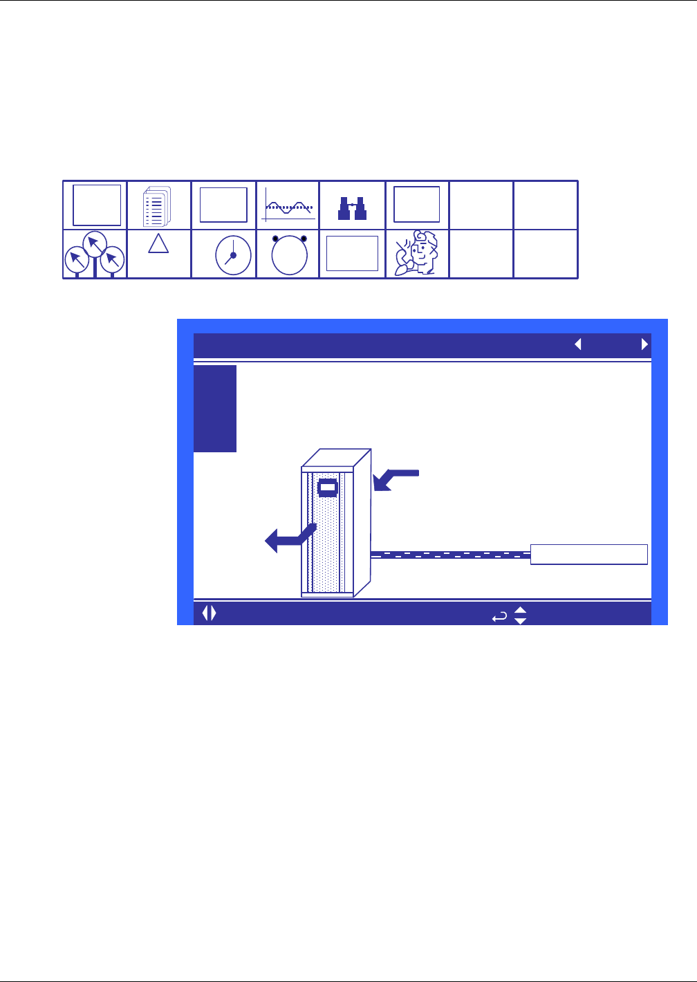
Liebert iCOM® Control
65 Liebert® CRV™
10.8 Liebert iCOM® User Menu Screens
User menus report general cooling unit operations and status. The user menu password is 1490.
The User menu parameter tables in this manual may differ from the display on your cooling unit. The
Liebert iCOM functions with several Liebert Precision Cooling units, each with its own set of control
commands. In addition, the Liebert iCOM control firmware is being updated constantly. As a result,
the User menu parameter tables in this manual may differ from the display on your cooling unit.
Check www.liebert.com for the latest Liebert iCOM user manual updates.
Figure 51 User menu icons
Figure 52 Setpoints parameters screen
Controlling Sensor—This parameter allows the user to select which sensor will be used to
determine the amount of cooling needed. This parameter can select only a single sensor for both the
temperature and fan speed control. Use the Service / Setpoints menu to decouple the operation of fan
speed to the remote sensors and the cooling capacity to the supply sensor.
Temperature Setpoint—This parameter allows the user to select a temperature that the cooling
unit will maintain by applying cooling and or reheats.
Humidity Setpoint—This parameter allows the user to select a humidity that the cooling unit will
maintain by removing or adding moisture to the air.
Spare Part List
Spare Parts—The spare parts lists contains a detailed description and part number that can be used
to order parts for the unit. These part numbers are specific to each model and option installed on the
unit.
Event Log
Event Log—The event log displays all events and actions that have been generated by the unit.
When multiple units are networked you will see the event log of the whole system. Each event shows
the unit that generated the alarm, time and date stamp, a description and the event type
EVENT
LOG
°C / °F
% RH
SET
SET
12
39
6
SET
ALARMS
!
ACTIVE
ALARMS
1234
h
RACK
VIEW
User Menu
password: 1490
U101
U102
U103
U104
PASSWORD (Actual Level 0) ????
Controlling Sensor Remote Sensor
Temperature Setpoint 68°F
Humidity Setpoint 45%
SETPOINTS UNIT 01
for next/previous unit to select parameter
Supply Sensor
Return Sensor
68° 45%
Remote Sensor

Liebert iCOM® Control
Liebert® CRV™66
View Network
View Network—The view network screen provides an overview of the Liebert iCOM® network and a
status of each unit. This screen will provide the unique unit name given to the unit. If no name is
given, then only the unit number will be displayed.
Figure 53 Sensor data parameters screen
Temperature Setpoint—This parameter shows the cooling setpoint, which is the setpoint used to
drive the compressor capacity. This parameter will automatically change based on which sensor is
used for control (Return, Supply or Remote sensor).
Actual Control Temperature—This parameter is the temperature reading of the actual sensor
that is referenced to U301. This parameter automatically changes based on the control sensor setting.
Fan Setpoint—This parameter defines the fan speed setpoint. This value is not shown when a single
sensor (Coupled Mode) is used to control cooling capacity and fan speed. This parameter is calculated
by adding the temperature setpoint and the fan speed delta in the Service / Setpoints menu.
Actual Fan Control Temp—This parameter is the temperature reading of the actual sensor that is
referenced to U303. This parameter automatically changes based on the control sensor settings.
Humidity Setpoint—This parameter allows the user to select a humidity that the cooling unit will
maintain by removing or adding moisture to the air. This parameter is adjustable from 20-80%. The
factory default setting from the factory is 50%.
Actual Return Humidity—This parameter is the return relative humidity reading of the sensor.
Actual Supply Humidity—This parameter is the calculated relative humidity of the supply sensor
based on the actual return humidity reading. This value is calculated by using a reverse look up
algorithm based on dew point.
Actual CW Temperature—This parameter displays the actual chilled water supply temperature
being delivered to the unit.
DigiScroll 1 Temperature—When digital scroll compressors are installed in the unit then the
actual digital scroll number 1 head temperature will be shown.
Active Alarms
Active Alarms—Permits viewing all current, active alarms.
This window is READ ONLY
U301
U302
U303
U304
U305
U306
U307
U308
U309
U310
U311
U312
Temperature Setpoint °F
Actual Control Temperature °F
Fan Setpoint °F
Actual Fan Control Temp °F
Humidity Setpoint %
Actual Return Humidity %
Actual Supply Humidity %
Actual CW Temperature °F
DigiScroll 1 Temperature °F
SENSOR DATA UNIT 01
Liebert iCOM® Control
67 Liebert® CRV™
Figure 54 Display setup parameters screen
Language—This parameter sets the language on the display. When this parameter is changed all
menu parameters will be converted to the selected language.
Date—This parameter sets the internal date of the unit. If this unit is connected to other units with
the unit to unit network connection. All units will reflect the last date set.
Time—This parameter sets the internal time of the unit. If this unit is connected to other units with
the unit to unit network connection. All units will reflect the last time set.
Temperature Indication—This parameter selects the actual and set point temperature indication.
Selecting C will set the unit to display in Celsius and F will set the unit to display in Fahrenheit.
Display Contrast—This parameter changes the contrast of the display to adjust for different
viewing angles, low light and bright light conditions. As the display ages the contrast may need to be
adjusted for better viewing clarity.
Buzzer Frequency—This parameter changes the audible noise frequency of the built in buzzer.
When adjusting the buzzer frequency the buzzer will sound allowing you to select a frequency that is
easily detected when an alarm occurs.
Backlite Off After—This parameter controls the length of time that the backlite remains active
when the display is unused. When the buttons on the front display have not been pressed for the time
selected in this parameter the backlite will turn off, extending the life of the display and saving
energy.
Screen—Multiple screen layouts exist for the CRV, Including Rack View and Trends to be
monitoring on the main display. Views include a Unit View with or without sensors, Rack View and
Graphical Data Record View. See Figure 49 for screen layouts.
Display Colors—This parameter selects the background color. Inverted sets the display to show
white font with blue background and Normal sets a white background with blue font.
Date Format—Date format changes the month, day and year arrangement shown on the front
display and on event time stamps.
to change parameter
for next/previous unit to select parameter
to confirm
then
S401
S402
S403
S404
S405
S406
S407
S408
S409
S410
S411
Language ENGLISH (US)
Date 7/17/2010
Time 09:20:19
Temperature Indication °F
Display Contrast 50
Buzzer Frequency Off/ 0
Backlite Off after 30 min
Screen Rack View
Display Colors Normal
Date Format mm/dd/yyyy
DISPLAY SETUP SYSTEM
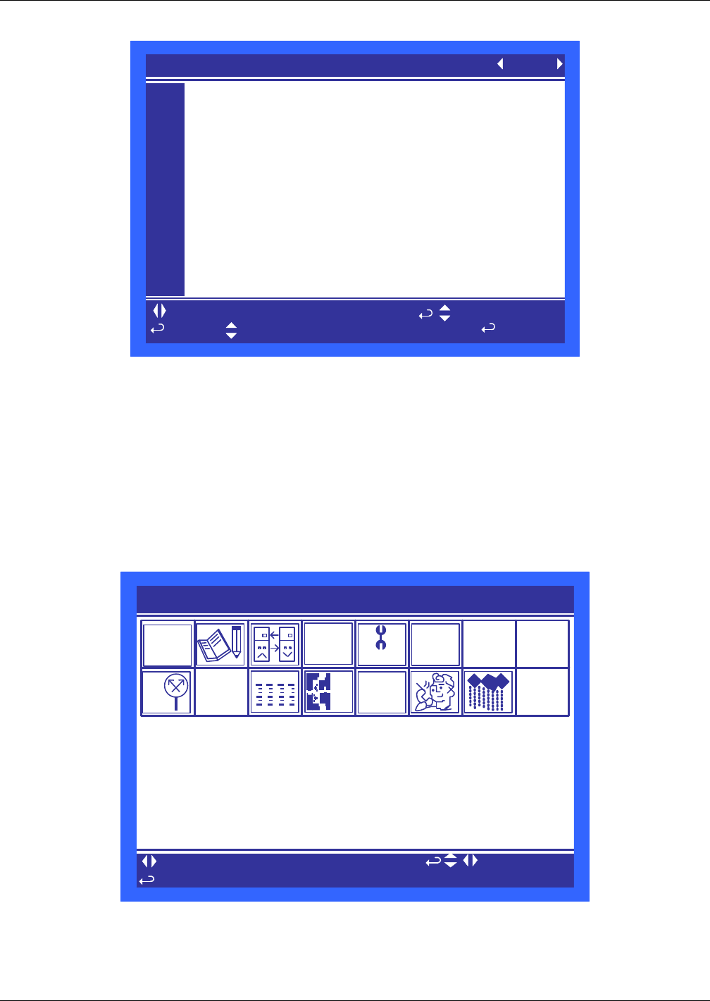
Liebert iCOM® Control
Liebert® CRV™68
Figure 55 Total run hours parameters screen
Each parameter shows the actual hours the component has operated and the maximum time the
component can operate before the next maintenance.
10.9 Liebert iCOM® Service Menu Screens
Service menus allow customized settings for site operations. The password for service menu
parameters is 5010.
The Liebert iCOM control firmware is being updated constantly. As a result, the Service menu
parameter tables shown in this manual may be slightly different than what is shown on your cooling
unit's display. Please check www.liebert.com for the latest Liebert iCOM User manual updates.
Figure 56 Service Menu Main Screen
U501
U502
U503
U504
U505
U506
U507
U508
U509
U510
U511
Actual Hours Limit
Fan Motor (s) 3513 0
Compressor 1 3511 0
Chilled Water 0 0
Electric Heater 0 0
Humidifier 160 0
Dehumidification 5 0
TOTAL RUN HOURS UNIT 01
to change parameter
for next/previous unit to select parameter
to confirm
then
SERVICE MENUS
to select parameter
to change level
to open requested menu
ESC
to unselect
to navigate
+
WELLNESS
SET
ALARMS
SERVICE
+/-
NETWORK SET
UP RACK
SETUP
°C / °F
% RH
SET

Liebert iCOM® Control
69 Liebert® CRV™
Figure 57 Setpoints parameters screen - Page 1
Temperature Setpoint—This parameter selects a temperature that the cooling unit will maintain
by applying cooling and or reheats. This parameter is adjustable from 41-104°F (5-40°C), the factory
default setting is 73°F (22.7°C).
Temperature Control Sensor—This sensor controls the cooling capacity of the Liebert CRV. If the
unit is chilled water model, then this sensor controls the chilled water valve opening. If the unit is a
DX (direct expansion) model then this sensor will control the amount of digital scroll capacity.
Temperature Control Type—This parameter selects the type of control the system will use to
activate cooling, heating, humidification and dehumidification. A detailed description of each control
type can be found in 3.7 - Supply Control.
Temperature Deadband—This parameter can be set to avoid overshooting of the setpoint and
cycling between the reheats and cooling. The value entered into this field will be split in half by the
temperature setpoint. Example—If the temperature setpoint is 70°F (21.1°C) and a 4°F (2.2°C)
deadband is set, then no cooling will be activated until 72°F (22.2°C) and no heating will be activated
until 68°F (20°C) is reached.
Cooling Proportional Band—This parameter adjusts the activation points of compressors or rate
of change based on the actual sensor values deviation from setpoint. The smaller this number the
faster the compressors and valve(s) will increase capacity. Too small of a number may cause the unit
to short cycle the compressors or excessively reposition the valve.
Cooling Integration/Derivative—Cooling integration takes into consideration the amount of time
the actual temperature has deviated from the setpoint. The longer this deviation exists the more
corrective action the unit will use to achieve the setpoint. The derivative term monitors the rate of
change and will reduce or increase the amount of corrective action based on the actual temperature
increasing or decreasing toward the temperature setpoint.
S101
S102
S103
S104
S105
S106
S107
S108
S109
S110
S111
PASSWORD (Actual Level 0) ????
Temperature Setpoint 68 °F
Temperature Control Sensor Remote Sensor
Temperature Control Type Proportional
Temperature Deadband 2°F
Cooling Proportional Band 9°F
Cooling Integration /Derivative min /sec
Heating Proportional Band 9°F
Heating Integration /Derivative min /sec
CRV Control Average
SETPOINTS (page 1 of 4) UNIT 01
to change parameter
for next/previous unit to select parameter
to confirm
then

Liebert iCOM® Control
Liebert® CRV™70
Figure 58 Setpoints parameters screen - Page 2
Humidity Setpoint—This parameter allows the user to select a humidity that the cooling unit will
maintain by removing or adding moisture to the air. This parameter is adjustable from 20-80%. The
factory default setting from the factory is 50%.
Humidity Control Type—This parameter selects the humidity control calculation. Setting this
parameter to “Relative” will control the humidity without considering any temperature deviations.
“Predictive” and “Absolute” control consider the temperature deviation from temperature setpoint so
that a constant level of moisture is kept in the area based on the humidity sensor reading and the
temperature deviation from setpoint. The factory default setting is “Predictive.”
Humidity Deadband—This parameter can be set to avoid overshooting of the setpoint and cycling
between humidification and dehumidification. The value entered into this field will be split in half by
the temperature setpoint. Example: If the humidity setpoint is 50% and a 4% deadband is set then no
humidity control will be activated between 48% and 52%.
Humidity Proportional Band—This parameter adjusts the activation points of the humidifier and
compressors based on the actual sensor values deviation from setpoint. The smaller this number the
faster the compressors and humidifier will increase capacity, too small of a number may cause the
unit to short cycle or overshoot setpoint.
Humidity Integration Time—This parameter adjusts the capacity of the unit based on time away
from setpoint so that accurate humidity control can be maintained. This parameter is only active
when Control Type is set to “PI.”
Dehum Proportional Band—The parameter adjusts the activation points of dehumidification
based on the actual sensor values deviation from setpoint. The smaller this number the faster the
compressors and humidifier will increase capacity, too small of a number may cause the unit to short
cycle or overshoot setpoint.
Dehum Integration Time—This parameter adjusts the capacity of the unit based on time away
from setpoint so that accurate humidity control can be maintained. This parameter is only active
when control type is set to “PI”.
Dehum/Heat Low Limit 1—This parameter sets the temperature at which the compressor will be
deactivated for dehumidification control. Example—If Low Limit 1 is set to 4°F (2.2°C) and the
temperature setpoint is 70°F (21.1°C), then dehumidification will turn off at 66°F (18.8°C).
Low Limit 1 reset—This parameter controls when the temperature has increased enough to re-
enable dehumidification.
S112
S113
S114
S115
S116
S117
S118
S119
S120
S121
S122
PASSWORD (Actual Level 0) ????
Humidity Setpoint 45%
Humidity Control Type PI
Humidity DeadBand 5%
Humidity Proportional Band 5%
Humidity Integration Time 0min
Dehum Proportional Band 5%
Dehum Integration Time 0min
Dehum/Heat Low Limit 1 -9°F
Low Limit 1 reset 0°F
SETPOINTS (page 2 of 4) UNIT 01
to change parameter
for next/previous unit to select parameter
to confirm
then
Liebert iCOM® Control
71 Liebert® CRV™
Figure 59 Setpoints parameters screen - Page 3
Fan Control Type—This parameter sets how the fan speed will be controlled. This parameter can be
set to Auto mode, which will allow the Liebert CRV to drive the fan based on the temperature sensor
selected for sensor control type. This parameter can also be set to Manual mode, which allows the
Liebert CRV to be set to a fixed fan speed either through the local display or through a building
management system.
Fan Control Sensor—This parameter sets which sensor will drive the Liebert CRV fans when set to
Auto mode for the fan control type.
Fan Regulation Type—This parameter is the fans’ control type. It can be set to Proportional
control, which will modulate the fans linearly based on the deviation from the setpoint. PI control is
also available and works in the same manner as the temperature control integral term.
Fan Delta—This parameter sets the fan speed setpoint. The delta accounts for the temperature rise
from the Supply Air Sensor and the Remote Rack sensors by adding the Fan Delta to the
Temperature Setpoint (S102). This eliminates the possibility of setting the remote rack temperature
setpoint lower than the supply temperature setpoint.
Fan Speed Proportional Band—This parameter adjusts the fans rate of change based on the
actual sensor values deviation from setpoint or the delta. The smaller this number the faster the fan
will increase its speed. Too small of a number may cause the fans to excessively reposition.
Fan Speed Integration—This parameter adjusts the fanspeed of the unit based on time away from
setpoint. This parameter is only active when Control Type is set to “PI.”
Fan Speed Manual Setpoint—This parameter sets the speed of the fans when the unit is placed
into Manual Fan Speed Control mode.
Fan Speed STD—This parameter sets the maximum fan speed of the unit under normal operating
circumstances.
Fan Speed Min—This parameter sets the lowest fan speed operation of the unit.
Fan Speed Dehum—This parameter sets the fan speed the unit will operate at during a call for
dehumidification. The fan speed will position to the highest requirement. If the call for fan speed from
the remote rack sensor is requesting more CFM than the Dehum fan speed, then the fans will run at
the remote sensor fan speed request.
S123
S124
S125
S126
S127
S128
S129
S130
S131
S132
S133
PASSWORD (Actual Level 0) ????
Fan Control Type Auto
Fan Control Sensor Remote Sensor
Fan Regulation Type
Fan Delta °F
Fan Speed Proportional Band °F
Fan Speed Integration min
Fan Speed Manual Setpoint %
Fan Speed STD 75%
Fan Speed Min 50%
Fan Speed Dehum 70%
SETPOINTS (page 3 of 4) UNIT 01
to change parameter
for next/previous unit to select parameter
to confirm
then
Liebert iCOM® Control
Liebert® CRV™72
Figure 60 Setpoints parameters screen - Page 4
MIN at CFC for EC Fan—This parameter can provide an offset to the minimum fan speed at the
minimum call for cooling. When set to 0 / 100 the MIN speed is reached when the call for fan is at 0%;
and the STD speed is reached when the call for fan reaches 100%.
For example, if the minimum is set to 20 and the standard is set to 90, the fan speed MIN is reached
earlier (the fan operates on lower speed compared to the calculated call for fan), and the STD speed is
reached faster when compared to the calculated call for fan.
STD at CFC for EC Fan—This parameter can provide an offset to the minimum fan speed at the
minimum call for cooling. When set to 0 / 100 the MIN speed is reached when the call for fan is at 0%;
and the STD speed is reached when the call for fan reaches 100%.
High Temp Limit Approach—This parameter sets the sensor that controls the fan speed maximum
override. This can be set to Disable, Supply or Return.
High Temp Limit Approach at— This parameter sets the temperature when the units fan speed
can operate above the maximum speed. The maximum override speed during this mode is set in
parameter A157 (Advanced menus).
Ball Valve Setpoint Offset—This parameter adjusts the operating compressor discharge pressure
by changing the targeted range of control. Available only on water-cooled units.
Unit Diary—Large Display Only
Shows all entered program changes and maintenance performed on the unit.
NOTE
The Liebert CRV fans are oversized and can be used to help protect equipment in emergency
situations, such as high temperature and a single fan failure.
Table 26 Unit diary parameters
Function Range
Imperial (metric)
Large Display Small Display
Page 1 of 1
Text entered with iST
(Liebert iCOM® Service Tool) N/A -
S134
S135
S136
S137
S138
S139
S140
S141
S142
S143
S144
PASSWORD (Actual Level 0) ????
MIN at CFC for EC Fan 0%
STD at CFC for EC Fan 100%
High Temp Limit Approach Supply
High Temp Limit Approach at 2°F
Ball Valve Setpoint Offset 0psig
SETPOINTS (page 4 of 4) UNIT 01
to change parameter
for next/previous unit to select parameter
to confirm
then
Liebert iCOM® Control
73 Liebert® CRV™
Figure 61 Standby settings / lead-lag parameters screen
Number of Standby Units—This parameter selects the number of units that will be in Standby
mode. When a unit is in standby mode the fan will be off and no cooling will be provided.
Rotation Frequency—This parameter controls when a rotation will occur between the standby
units and the operating units within a network.
Rotate at (hour)—This parameter sets the hour of the rotation
Rotate at (minute)—This parameter sets the minute of the rotation
Rotate by—This parameter determines the number of positions to rotate by. Example: If there are 6
units in a unit to unit network and units 1, 3 & 5 are in standby and this parameter is set to “1” then
at the next rotation units 2, 4,& 6 will be placed into standby and 1, 3 & 5 will become operational.
Perform one Rotation—This parameter will manually force a single rotation between units.
Cascade Units—This parameter when set allows units to activate from Standby mode if the room
temperature is unable to be maintained by the non-standby units. If yes is selected then the cascade
units can perform all functions when activated from standby. This parameter can also be set for
Cooling Only or Cool / Heat only.
Start all Standby Units by HT—This parameter activates all units to cool when a High
Temperature alarm occurs.
See 3.9.1 - Calculation of Next Maintenance and Diagnostics for details on these menus.
S501
S502
S503
S504
S505
S506
S507
S508
S509
S510
S511
PASSWORD (Actual Level 0) ????
Number of Standby Units 0
Rotation Frequency
Rotate at (hour)
Rotate at (minute)
Rotate by
Perform one Rotation
Cascade Units
Start all Standby Units by HT
STANDBY SETTINGS/LEAD-LAG SYSTEM
to change parameter
for next/previous unit to select parameter
to confirm
then
Liebert iCOM® Control
Liebert® CRV™74
Figure 62 Wellness basic settings screen- Page 1
Maintenance Frequency Per Year—This parameter sets the number of expected maintenance
visits in a one year time span.
Max Bonus—This parameter will increase the time to the next maintenance cycle. A bonus should be
assigned when a service visit finds that all components are working optimally.
Max Penalty—This parameter will decrease the time to the next maintenance cycle. A penalty
should be used when a service visit finds excessive wear on components.
Last Maintenance—This parameter is set during the service call. It also indicates to other service
personnel the date of the last visit.
Service Engineer—This parameter provides a label for the service representative to list either the
company name or representative’s name.
Confirm PM—This parameter confirms that the service representative has completed the preventive
maintenance and resets the next maintenance date.
Calculated Next Maintenance—This parameter provides a date to when the next expected
maintenance should take place based on the last confirmed PM, component starts, run hours and the
penalty / bonus currently set in the Liebert iCOM® control.
S001
S002
S003
S004
S005
S006
S007
S008
S009
S010
S011
PASSWORD (Actual Level 0) ????
Maintenance Frequency Per Year 1
Max Bonus 0
Max Penalty 0
Last Maintenance 06/14/2010
Service Engineer Nobody
Confirm PM No
Calculated Next Maintenance 06/2011
WELLNESS basic settings (page 1 of 5) SYSTEM
to change parameter
for next/previous unit to select parameter
to confirm
then
Liebert iCOM® Control
75 Liebert® CRV™
Figure 63 Wellness motor settings parameters screen - Page 2
Number of Starts—This parameter shows the number of starts for the unit’s fans.
Run Hours—This parameter shows the number of run hours for the unit’s fan.
Average Run Time—This parameter displays the average run time of the unit’s fan.
Starts per Day Best—This parameter displays the lowest number of starts in a rolling 24 hour
period.
Starts per Day Worst—This parameter displays the highest number of starts in a rolling 24 hour
period.
Number of Alarms—This parameter displays the number of alarms that have occurred with the
unit’s fans.
Actual Bonus—This parameter displays the actual calculation of wellness for the unit’s fans. The
unit will always take the value from the worst component for the next maintenance indication.
S012
S013
S014
S015
S016
S017
S018
S019
S020
S021
S022
PASSWORD (Actual Level 0) ????
Number of Starts 21
Run Hours 3376 hrs
Average Run Time 9645 min
Starts per Day Best 1
Starts per Day Worst 24
Number of Alarms 0
Actual Bonus 0
WELLNESS motor settings (page 2 of 5) UNIT 1
to change parameter
for next/previous unit to select parameter
to confirm
then
Liebert iCOM® Control
Liebert® CRV™76
Figure 64 Wellness compressor 1 settings parameters screen - Page 3
Number of Starts—This parameter shows the number of starts for the unit’s compressor.
Run Hours—This parameter shows the number of run hours for the unit’s compressor.
Average Run Time—This parameter displays the average run time of the unit’s compressor.
Starts per Day Best—This parameter displays the lowest number of starts in a rolling 24 hour
period.
Starts per Day Worst—This parameter displays the highest number of starts in a rolling 24 hour
period.
Number of HP Alarms—This parameter displays the number of high pressure alarms that have
occurred with the unit’s compressor.
Number of LP Alarms—This parameter displays the number of low pressure alarms that have
occurred with the unit’s compressor.
Number of OL Alarms—This parameter displays the number of overload alarms that have occurred
with the unit’s compressor.
Number of DS HT Alarms—This parameter displays the number of Digital Scroll High
Temperature alarms that have occurred with the unit’s compressor.
Actual Bonus—This parameter displays the actual calculation of wellness for the unit’s compressor.
The unit will always take the value from the worst component for the next maintenance indication.
S023
S024
S025
S026
S027
S028
S029
S030
S031
S032
S033
PASSWORD (Actual Level 0) ????
Number of Starts 22
Run Hours 3374hrs
Average Run Time 9201 min
Starts per Day Best 12
Starts per Day Worst 240
Number of HP Alarms 0
Number of LP Alarms 0
Number of OL Alarms 0
Number of DS HT Alarms 0
Actual Bonus 0
WELLNESS compressor1 settings (page 3 of 5) UNIT 1
to change parameter
for next/previous unit to select parameter
to confirm
then
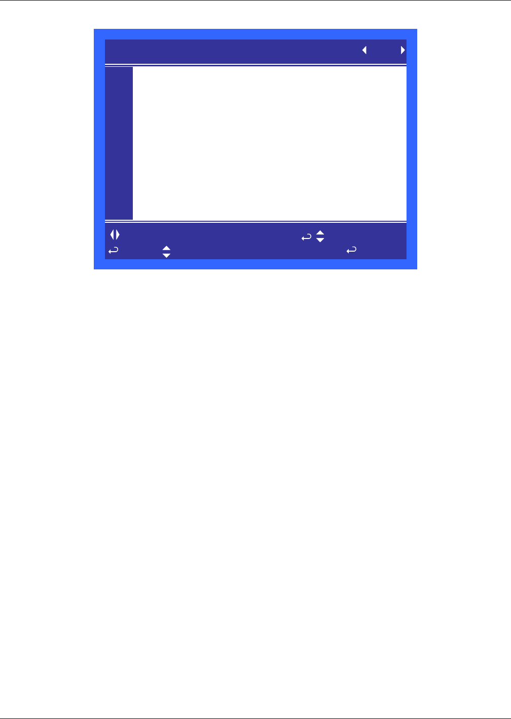
Liebert iCOM® Control
77 Liebert® CRV™
Figure 65 Wellness electric heater 1 settings parameters screen - Page 4
Number of Starts—This parameter shows the number of starts for the unit’s reheats.
Run Hours—This parameter shows the number of run hours for the unit’s reheats.
Average Run Time—This parameter displays the average run time of the unit’s reheats.
Starts per Day Best—This parameter displays the lowest number of starts in a rolling 24 hour
period.
Starts per Day Worst—This parameter displays the highest number of starts in a rolling 24 hour
period.
Number of HP Alarms—This parameter displays the number of high pressure alarms that have
occurred with the unit’s reheats.
Actual Bonus—This parameter displays the actual calculation of wellness for the unit’s reheats. The
unit will always take the value from the worst component for the next maintenance indication.
S034
S035
S036
S037
S038
S039
S040
S041
S042
S043
S044
PASSWORD (Actual Level 0) ????
Number of Starts 0
Run Hours 0hrs
Average Run Time 0min
Starts per Day Best 24
Starts per Day Worst 240
Number of HP Alarms 0
Actual Bonus 0
WELLNESS el heater 1 settings (page 4 of 5) UNIT 1
to change parameter
for next/previous unit to select parameter
to confirm
then
Screen displayed
only if unit is
equipped with
electric heater
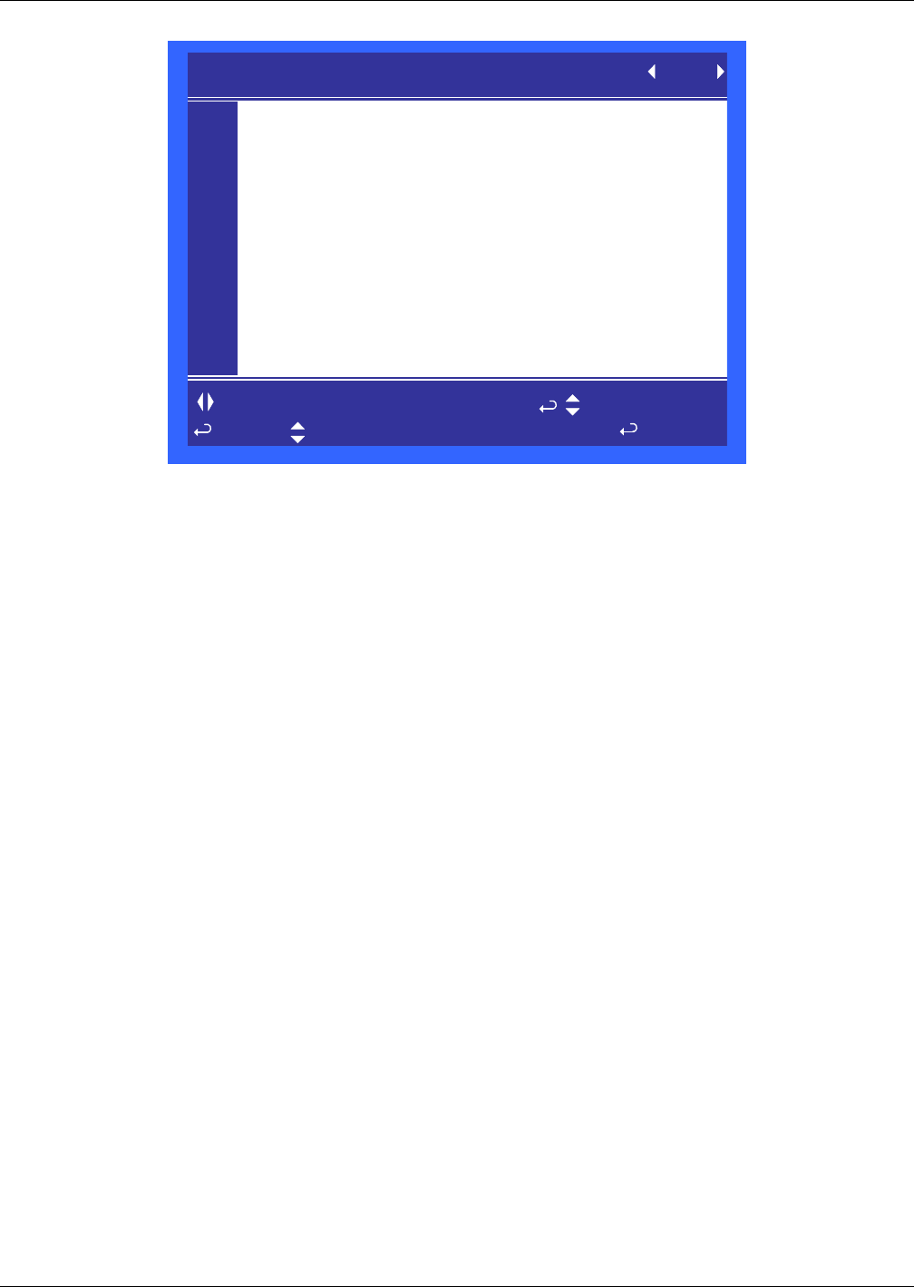
Liebert iCOM® Control
Liebert® CRV™78
Figure 66 Wellness humidifier settings parameters screen - Page 5
Number of Starts—This parameter shows the number of starts for the unit’s humidifier.
Run Hours—This parameter shows the number of run hours for the unit’s humidifier.
Average Run Time—This parameter displays the average run time of the unit’s humidifier.
Starts per Day Best—This parameter displays the lowest number of starts in a rolling 24 hour
period.
Starts per Day Worst—This parameter displays the highest number of starts in a rolling 24 hour
period.
Number of Alarms—This parameter displays the number of high pressure alarms that have
occurred with the unit’s humidifier.
Actual Bonus—This parameter displays the actual calculation of wellness for the unit’s humidifier.
The unit will always take the value from the worst component for the next maintenance indication.
S045
S046
S047
S048
S049
S050
S051
S052
S053
S054
S055
PASSWORD (Actual Level 0) ????
Number of Starts 14404
Run Hours 154 hrs
Average Run Time 0min
Starts per Day Best 24
Starts per Day Worst 240
Number of Alarms 0
Actual Bonus 0
WELLNESS humidifier settings (page 5 of 5) UNIT 1
to change parameter
for next/previous unit to select parameter
to confirm
then
Screen displayed
only if unit is
equipped with
humidifier
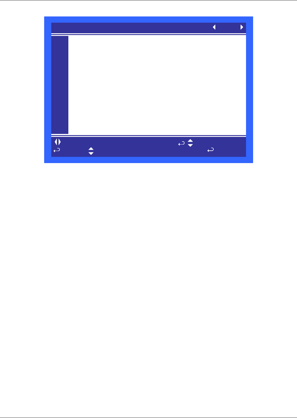
Liebert iCOM® Control
79 Liebert® CRV™
Figure 67 Diagnostics / service mode parameters screen - Page 1
HP 1 Alarm Code—Compressor 1 high pressure alarm code.
LP 1 Alarm Code—Indicates which phase compressor 1 is operating in. For more information on
this refer to the Liebert iCOM® Training and Service manual’s low pressure transducer flow chart.
HT 1 Alarm Counter—Compressor 1 high temperature event alarm counter. If more than five
events in a rolling 4 hour period occur then the compressor will be locked out.
12h Dehum Counter—
Low Supply Temperature Counter—
Actual LP1 Pressure—Current refrigerant low pressure side reading in atmosphere for
Compressor 1.
Actual HP1 Pressure—Current refrigerant high pressure side liquid reading in atmosphere for
Compressor 1. (This is available only on water cooled units equipped with motorized ball valves.)
to change parameter
for next/previous unit to select parameter
to confirm
then
S301
S302
S303
S304
S305
S306
S307
S308
S309
S310
S311
PASSWORD Actual Level 0) ????
HP 1 Alarm Code 0
LP 1 Alarm Counter 0
HT1 Alarm Counter 0
12h Dehum Counter 0
Low Supply Temperature Counter 0
Actual LP1 Pressure 169psig
Actual HP1 Pressure 338psig
DIAGNOSTICS/SERVICE MODE (page 1 of 6) UNIT 01
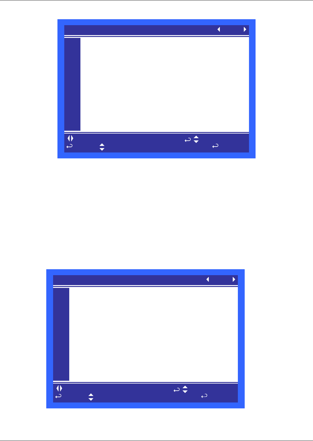
Liebert iCOM® Control
Liebert® CRV™80
Figure 68 Diagnostics / service mode parameters screen - Page 2
Manual Mode—Use this setting to place the Liebert iCOM® control in manual mode. This is the
initial setting necessary to activate any of the following items.
Motor(s)—Setting this option to ON will start the main fan of the unit. Note that the main fan must
be On in order to activate any of the following overrides.
Compressor 1—Use this setting to turn on compressor 1 and select the mode of compressor
operation. The operation selections are RUN, EVACUATE and CHARGE.
Compressor 1 Capacity—Use this setting to enable Compressor 1 Cycle Ramp.
Compressor 1 Cycle Ramp—This setting allows the user to select the capacity the compressor
should run at. Range on this is 0 – 100%.
Compressor 1 LLSV—This option will control the liquid line solenoid valve for compressor 1.
Figure 69 Diagnostics / service mode parameters screen - Page 3
Electric Heat 1 (or HG/HW)—This will activate stage 1 of the unit’s reheat system.
Dehumidification Output—This activates the dehumidification cycle.
to change parameter
for next/previous unit to select parameter
to confirm
then
S312
S313
S314
S315
S316
S317
S318
S319
S320
S321
S322
PASSWORD Actual Level 0) ????
Manual Mode No
Motor(s) On
Compressor 1 Run On
Compressor 1 Capacity On
Compressor 1 Cycle Ramp 76%
Compressor 1 LLSV On
DIAGNOSTICS/SERVICE MODE (page 2 of 6) UNIT 01
to change parameter
for next/previous unit to select parameter
to confirm
then
S323
S324
S325
S326
S327
S328
S329
S330
S331
S332
S333
PASSWORD Actual Level 0) ????
Electric Heat 1 Off
Dehumidification Output Off
Humidifier Fill
Humidifier Off
Humidifier Drain
Humidifier Current A
DIAGNOSTICS/SERVICE MODE (page 3 of 6) UNIT 01
Liebert iCOM® Control
81 Liebert® CRV™
Humidifier Fill—This activates just the humidifier water source solenoid valve which fills the
humidifier pan or canister with water.
Humidifier—This activates the humidifier system in its entirety.
Humidifier Drain—This activates just the humidifier drain solenoid in the case of the steam
generating humidifier, allowing water to drain from the canister.
Humidifier Current—In the case of the steam generating humidifier option this setting shows the
amount of AC amperes the system is consuming.
Figure 70 Diagnostics / service mode parameters screen - Page 4
Alarm Relay—This allows the user to activate the Liebert iCOM® control’s common alarm relay
output.
Warning Relay—This allows the user to activate the Liebert iCOM control’s free-cooling relay
output.
3P Actuator Open—This setting will energize the open circuit of the 3P type chilled or freecooling
control valve thus journeying it to the open state.
3P Actuator Close—This setting will energize the close circuit of the 3P type chilled or freecooling
control valve thus journeying it to the closed state.
Current Fanspeed (Read only)—Shows the analog output for the fan in automatic mode.
Fanspeed Manual Setpoint (Read only)—Drives the analog output for the fan in manual mode.
Condenser Control Mode—Defines the condenser control mode in manual or auto mode during
compressor manual mode.
Current MBV / CWV (AnaOut2) (Read only)—Shows the analog output for the MBV (motorized
ball valve) or analog CWV (chilled water valve) in automatic mode.
Manual MBV (AnaOut2)—Drives the analog output for the condenser valve (MBV) in manual
mode.
Manual CWV (AnaOut2)—Drives the analog output for the analog CWV (chilled water valve) in
manual mode.
to change parameter
for next/previous unit to select parameter
to confirm
then
S334
S335
S336
S337
S338
S339
S340
S341
S342
S343
S344
PASSWORD (Actual Level 0) ????
Alarm Relay Off
Warning Relay Off
3P Actuator Open Off
3P Acuator Close Off
Current Fanspeed
Fanspeed Manual Setpoint
Condenser Control Mode Auto
Current MBV /CWV (AnaOut 2) 75%
Manual MBV (AnaOut 2) 100%
Manual CWV (AnaOut 2) %
DIAGNOSTICS/SERVICE MODE (page 4 of 6) UNIT 01
Liebert iCOM® Control
Liebert® CRV™82
Figure 71 Diagnostics / service mode parameters screen - Page 5
Status Remote Shutdown—This show the status of the unit’s remote shut down input.
Status Airflow 1 & 2—This show the status of the unit’s air proof switches.
Status Filter—This shows the status of the unit’s filter clog switch input.
Status Customer Input 1, 2, 3 & 4—This shows the status of the unit’s customer inputs.
Status LSI—
Status Heaters Safety—(HPM and PEX only) This parameter shows the status of the unit’s reheat
safety switch.
Figure 72 Diagnostics / service mode parameters screen - Page 6
Status HP1—This shows the status of the unit’s compressor 1 high pressure switch input.
Status LP1—This shows the status of the unit’s compressor 1 low pressure switch input.
Status LWD—This shows the status of the unit’s Leakage Water Detector.
Status Liquitech—This shows the status of the unit’s Liebert Liqui-tect® liquid detection setup.
to change parameter
for next/previous unit to select parameter
to confirm
then
S345
S346
S347
S348
S349
S350
S351
S352
S353
S354
S355
PASSWORD Actual Level 0) ????
Status Remote Shutdown o-o On
Status Airflow 1 o-o OK
Status Airflow 2 o-o OK
Status Filter o-o OK
Status Customer Input 1 o/o OK
Status Customer Input 2 o/o OK
Status Customer Input 3 o/o OK
Status Customer Input 4 o/o OK
Status LSI o-o OK
Status Heaters Safety o/o Act
DIAGNOSTICS/SERVICE MODE (page 5 of 6) UNIT 01
to change parameter
for next/previous unit to select parameter
to confirm
then
S356
S357
S358
S359
S360
S361
S362
S363
S364
S365
S366
PASSWORD Actual Level 0) ????
Status HP1 o/o OK
Status LP 1 o-o OK
Status LWD %
Status Liquitech
DIAGNOSTICS/SERVICE MODE (page 6 of 6) UNIT 01

Liebert iCOM® Control
83 Liebert® CRV™
Figure 73 Set alarms parameters screen - Page 1
Temp/Hum Events—This parameter enables or disables all of the temperature and humidity
events.
High Supply Temperature—This parameter sets the high temperature threshold that will trigger
an alarm on the Liebert iCOM® local display and any monitoring system that may be connected.
Low Supply Temperature—This parameter sets the low temperature threshold that will trigger an
alarm on the Liebert iCOM local display and any monitoring system that may be connected.
High Return Temperature—This parameter sets the threshold temperature when a return high
temperature alarm will occur.
High Return Humidity—This parameter sets the threshold humidity when a return high humidity
alarm will occur.
Low Return Humidity—This parameter sets the threshold humidity when a return low humidity
alarm will occur.
High CW Temperature—This parameter sets the threshold chilled water when a return high
chilled water temperature alarm will occur.
S201
S202
S203
S204
S205
S206
S207
S208
S209
S210
S211
PASSWORD (Actual Level 0) ????
Tem/Hum Events Enabled
High Supply Temperature 80 °F
Low Supply Temperature 46 °F
High Return Temperature 104 °F
High Return Humidity 60 %
Low Return Humidity 15 %
High CW Temperature °F
SET ALARMS (page 1 of 4) UNIT 01
to change parameter
for next/previous unit to select parameter
to confirm
then
Liebert iCOM® Control
Liebert® CRV™84
Figure 74 Set alarms parameters screen - Page 2
Customer Input 1, 2, 3 & 4—These parameters select the device and operation of the customer
inputs. Each event reflects a different alarm and possible action to the unit. Refer to table 7 for a
description of selectable options.
Customer Input 1, 2, 3 & 4 active when—These parameters select whether the input is a normally
closed or normally closed input.
Figure 75 Set alarms parameters screen - Page 3
This screen selects the operation of an active alarm. Each event can be enabled or disabled and can be
set to operate as an alarm, warning or message. The delay is the time the control waits before
reporting the event.
• Alarm: Annunciates the buzzer, triggers a monitoring event, triggers the alarm relay and flashes
the red LED on the display
• Warning / Alarm: Annunciates the buzzer, triggers a monitoring event, shows the event in the
event viewer / front display and flashes the red LED on the display.
• Message: Shows the event in the event viewer and on the front display.
S211
S212
S213
S214
S215
S216
S217
S218
S219
S220
S221
PASSWORD (Actual Level 0) ????
Customer Input 1 Smoke Alarm
Customer Input 1 active when Closed
Customer Input 2 Fire Alarm
Customer Input 2 active when Closed
Customer Input 3 C PMP Alarm SD
Customer Input 3 active when Closed
Customer Input 4 HUM
Customer Input 4 active when Closed
SET ALARMS (page 2 of 4) UNIT 01
to change parameter
for next/previous unit to select parameter
to confirm
then
S223
S224
S225
S226
S227
S228
S229
S230
S231
S232
S233
PASSWORD (Actual Level 0) ????
DELAY EN-DIS TYPE
LOSS OF POWER ENABLE WRN
SMOKE DETECTED 5 ENABLE ALM
WATER UNDER FLOOR 5 ENABLE ALM
LOSS OF FLOW 5 ENABLE ALM
CUSTOMER INPUT 1 5 ENABLE ALM
REHEAT LOCKOUT 5 ENABLE ALM
HUMIDIFIER LOCKOUT 5 ENABLE ALM
COMPRESSOR(S) LOCKOUT 5 ENABLE ALM
SET ALARMS (page 3 of 4) UNIT 01
to change parameter
for next/previous unit to select parameter
to confirm
then

Liebert iCOM® Control
85 Liebert® CRV™
Figure 76 Set alarms parameters screen - Page 4
This screen selects the operation of an active alarm. Each event can be enabled or disabled and can be
set to operate as an alarm, warning or message. The delay is the time the control waits before
reporting the event.
• Alarm: Annunciates the buzzer, triggers a monitoring event, triggers the alarm relay and flashes
the red LED on the display
• Warning / Alarm: Annunciates the buzzer, triggers a monitoring event, shows the event in the
event viewer / front display and flashes the red LED on the display.
• Message: Shows the event in the event viewer and on the front display.
S234
S235
S236
S237
S238
S239
S240
S241
S242
S243
S244
S245
S246
PASSWORD (Actual Level 0) ????
DELAY EN-DIS TYPE
CALL SERVICE 5 ENABLE ALM
HIGH TEMPERATURE 5 ENABLE ALM
HEAT REJ VFD 0 ENABLE ALM
HEAT REJ TVSS 0 ENABLE ALM
CONDENSER 1 FAILURE 0 ENABLE WRN
CUSTOMER INPUT 2 5 ENABLE ALM
CUSTOMER INPUT 3 5 ENABLE ALM
CUSTOMER INPUT 4 5 ENABLE ALM
SET ALARMS (page 4 of 4) UNIT 01
Liebert iCOM® Control
Liebert® CRV™86
Figure 77 Sensor calibration / setup parameters - Page 1
Return Temperature—This parameter adjusts the return temperature reading from the actual
sensor to compensate for any error of the sensor or to match other sensors in the room.
Calibrated Return Temperature—This parameter shows the adjusted temperature value of the
return sensor. This value is the actual sensor reading (+ or -) the offset “Return Temperature”.
Return Humidity—This parameter adjusts the return humidity reading from the actual sensor to
compensate for any error of the sensor or to match other sensors in the room.
Calibrated Return Humidity—This parameter shows the adjusted humidity value of the return
sensor. This value is the actual sensor reading (+ or -) the offset “Return Humidity”.
Digiscroll 1 NTC—This parameter adjusts the digital scroll 1 NTC reading from the actual sensor to
compensate for any error or drift of the sensor.
Calibrated Digiscroll 1 NTC—This parameter shows the adjusted Digital Scroll 1 NTC sensor
value. This value is the actual sensor reading (+ or -) the offset “Digital Scroll 1 NTC”.
Figure 78 Sensor calibration / setup parameters - Page 2
to change parameter
for next/previous unit to select parameter
to confirm
then
S601
S602
S603
S604
S605
U606
S607
S608
S609
S610
S611
PASSWORD Actual Level 0) ????
Return Temperature +0°F
Calibrated Return Temperature 77°F
Return Humidity +0.0%
Calibrated Return Humidity 26.0%
Digiscroll 1 NTC +0°F
Calibrated Digiscroll 1 NTC 200°F
SENSOR CALIBRATION/SETUP (page 1 of 4) UNIT 01
to change parameter
for next/previous unit to select parameter
to confirm
then
S612
S613
S614
S615
S616
S617
S618
S619
S620
S621
S622
PASSWORD Actual Level 0) ????
Return T Sensor PTC or NTC NTC
Return T Sensor +0°F
Calibrated Return T Sensor °F
Supply T Sensor PTC or NTC NTC
Supply T Sensor +1°F
Calibrated Supply T Sensor 75°F
CW T Sensor °F
Calibrated CW T Sensor °F
SENSOR CALIBRATION/SETUP (page 2 of 4) UNIT 01

Liebert iCOM® Control
87 Liebert® CRV™
Return T Sensor PTC or NTC—This parameter selects the type of sensor being used for the return
air sensor.
Return T Sensor—This parameter can provide an offset to the actual sensor reading to calibrate the
units sensor to other sensors.
Calibrated Return T Sensor—This parameter is the reading after the offset has been added to or
subtracted from the actual sensor reading.
Supply T Sensor PTC or NTC—This parameter sets the type of sensor that is connected to the
unit. It is set at the factory as NTC and should be changed only by a certified Emerson technician.
Supply T Sensor—This parameter can provide an offset to the actual sensor reading to calibrate the
unit’s sensor to other sensors.
Calibrated Supply T Sensor—This parameter is the reading after the offset has been added to or
subtracted from the actual sensor reading.
CW T Sensor—This parameter can provide an offset to the actual sensor reading to calibrate the
unit’s sensor to other sensors.
Calibrated CW T Sensor—This parameter is the reading after the offset has been added to or
subtracted from the actual sensor reading.
Figure 79 Sensor calibration / setup parameters - Page 3
This unit can be equipped with a total of 20 rack sensor readings or 10 2T temperature sensor
modules. This menu provides the ability to calibrated by entering a negative or positive offset. The
calibrated reading is displayed in the far right column. If a value is not shown in the far right column,
then the sensor is either not setup correctly or is not connected.
to change parameter
for next/previous unit to select parameter
to confirm
then
S623
S624
S625
S626
S627
S628
S629
S630
S631
S632
S633
PASSWORD Actual Level 0) ????
Rack Temperature Sensor 1 +0°F 77°F
Rack Temperature Sensor 2 +0°F 78°F
Rack Temperature Sensor 3 +0°F 77°F
Rack Temperature Sensor 4 +0°F 77°F
Rack Temperature Sensor 5 +0°F 78°F
Rack Temperature Sensor 6 +0°F °F
Rack Temperature Sensor 7 +0°F °F
Rack Temperature Sensor 8 +0°F °F
Rack Temperature Sensor 9 +0°F °F
Rack Temperature Sensor 10 +0°F °F
SENSOR CALIBRATION/SETUP (page 3 of 4) UNIT 01
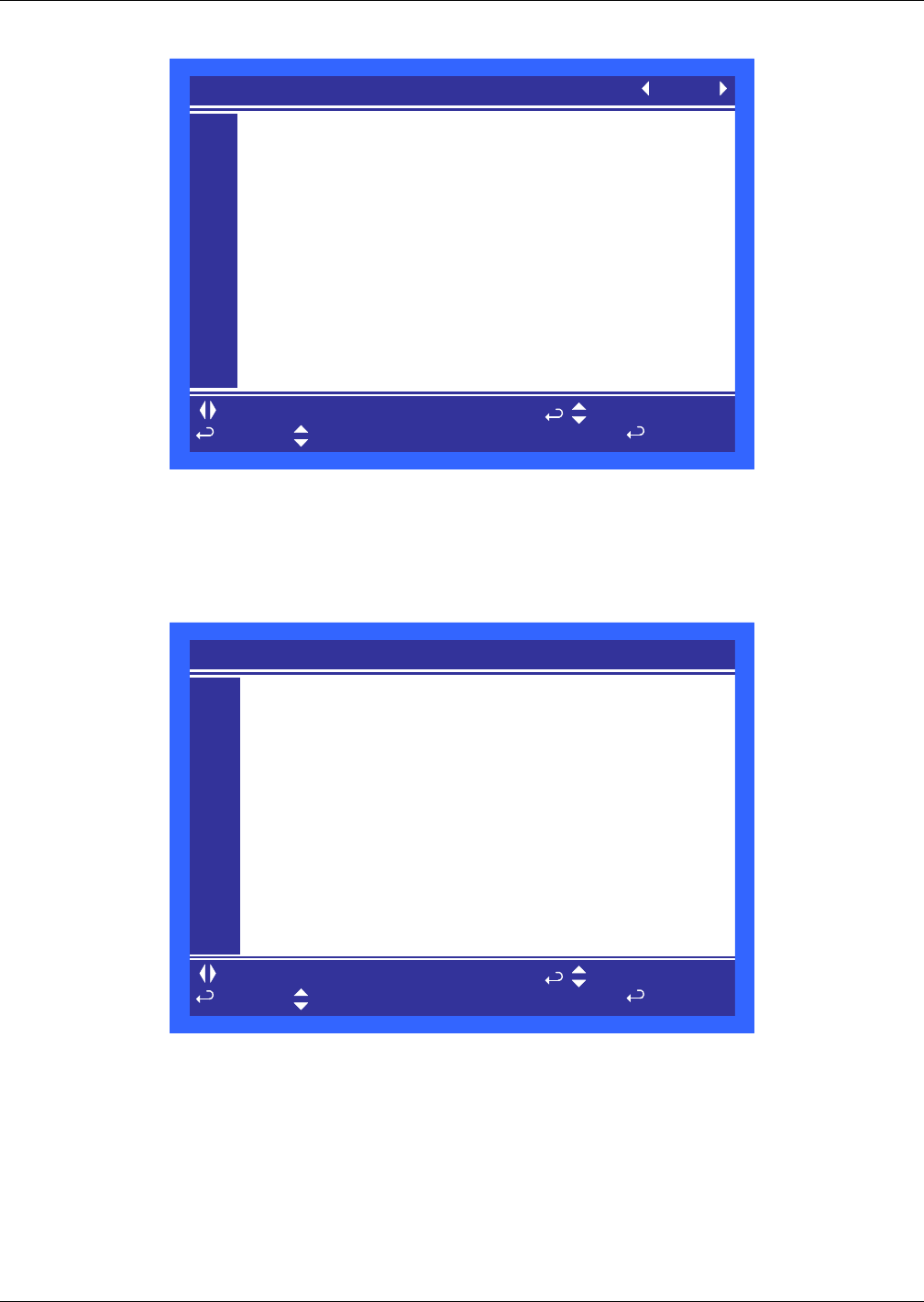
Liebert iCOM® Control
Liebert® CRV™88
Figure 80 Sensor calibration / setup parameters - Page 4
This unit can be equipped with a total of 20 rack sensor readings or 10 2T temperature sensor
modules. This menu provides the ability to calibrated by entering a negative or positive offset. The
calibrated reading is displayed in the far right column. If a value is not shown in the far right column,
then the sensor is either not setup correctly or is not connected.
Figure 81 System / network setup parameters—System - Page 1
Number of Connected Units—This parameter sets the number of units that will be viewable from
the large display and will participate on the unit to unit network.
Teamwork Mode—This parameter selects which teamwork mode to use within a selected group.
Teamwork modes are described in section 4.0 of this manual.
Teamwork Mode 1 based on—
Configuration Safe—This parameter saves or loads configuration settings for the display that have
been modified from the factory defaults to an internal file that can be downloaded / uploaded using
the Liebert iCOM® Service Tool. Selecting “Save” will write the settings to the internal storage file
and selecting “Load” will write the settings from the internal storage file to the application software.
The internal file is updated every 12 hours automatically.
to change parameter
for next/previous unit to select parameter
to confirm
then
S634
S635
S636
S637
S638
S639
S640
S641
S642
S643
S644
PASSWORD Actual Level 0) ????
Rack Temperature Sensor 1B °F 77°F
Rack Temperature Sensor 2B °F 78°F
Rack Temperature Sensor 3B °F 77°F
Rack Temperature Sensor 4B °F 77°F
Rack Temperature Sensor 5B °F 78°F
Rack Temperature Sensor 6B +0°F °F
Rack Temperature Sensor 7B +0°F °F
Rack Temperature Sensor 8B +0°F °F
Rack Temperature Sensor 9B +0°F °F
Rack Temperature Sensor 10B +0°F °F
SENSOR CALIBRATION/SETUP (page 4 of 4) UNIT 01
S801
S802
S803
S804
S805
S806
S807
S808
S809
S810
S811
PASSWORD (Actual Level 0) ????
Number of Connected Units 1
Teamwork Mode No
Teamwork Mode 1 based on
Configuration Safe OK No
Network Safe OK No
SW Version CRB 2.00.006.STD
SYSTEM / NETWORK SETUP (page 1 of 2) SYSTEM
to change parameter
for next/previous unit to select parameter
to confirm
then
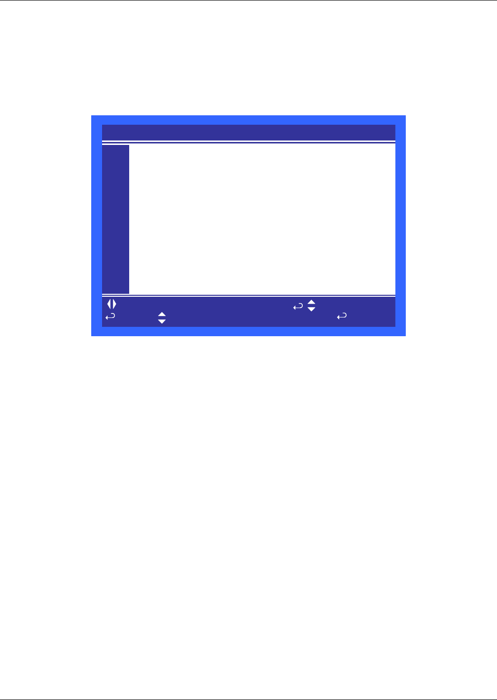
Liebert iCOM® Control
89 Liebert® CRV™
Network Safe—This parameter saves or loads network settings for the display that have been
modified from the factory defaults to an internal file that can be downloaded / uploaded using the
Liebert iCOM® Service Tool. Selecting “Save” will write the settings to the internal storage file and
selecting “Load” will write the settings from the internal storage file to the application software.
SW Version—This parameter contains the application software version loaded into the Liebert
iCOM display.
Figure 82 System / network setup parameters—large display only System - Page 2
IP Address—This parameter contains the network address of the display. This address must be
unique to every other device on the network.
Netmask—Not currently used.
Gateway—Not currently used.
MAC—The MAC address is a unique hardware identifier of the Ethernet device.
U2U Protocol—This parameter is always set to GBP.
U2U Address—This parameter is a unique identifier for each unit on the network. Display addresses
range from 33 to 64. Each display on the U2U network must have a different U2U address.
U2U Group—This parameter is used to create zones or groups within a U2U network. Once a group
number is selected the display will only see other devices with the same group number. The group
number can be changed to view other devices in different groups.
Bootloader Variables—This parameter indicates if there has been a change to the bootloader since
it was last loaded. This parameter should only be activated by an authorized service person.
S812
S813
S814
S815
S816
S817
S818
S819
S820
S821
S822
PASSWORD (Actual Level 0) ????
IP Address 10.203.062.150
Netmask 255.255.255.192
Gateway 10.203.062.129
MAC 00:00:68:19:0B:58
U2U Protocol GBP
U2U Address 33
U2U Group 13
Bootloader Variables Changed No
SYSTEM / NETWORK SETUP (page 2 of 2) SYSTEM
to change parameter
for next/previous unit to select parameter
to confirm
then

Liebert iCOM® Control
Liebert® CRV™90
Figure 83 System/Network setup parameters Unit- Page 1
Monitoring Address—This parameter sets the address used by the Liebert IntelliSlot® cards. This
is set to 3 from the factory and should not be changed.
Monitoring Timeout/Handshake—This parameter can be used with a building management
system to verify communications has not been lost between the Liebert iCOM® control and the BMS.
If the amount of time specified in this parameter elapses before the BMS writes a new value then an
alarm will occur “BMS TIMEOUT” and the temperature setpoint will revert to the backup setpoint
and the fan speed “if equipped” will change to 100%. To disable this feature write a zero to this
parameter when it is active.
Unit Name—This parameter is a label to identify the unit from the local or remote display. This label
will show at the top right of every screen that has monitoring or configuration of that unit.
Configuration Safe—This parameter saves or loads configuration settings for the control board that
have been modified from the factory defaults to an internal file that can be downloaded / uploaded
using the Liebert iCOM Service Tool. Selecting “Save” will write the settings to the internal storage
file and selecting “Load” will write the settings from the internal storage file to the application
software. The internal file is updated every 12 hours automatically.
Network Safe—This parameter saves or loads network settings for the control board that have been
modified from the factory defaults to an internal file that can be downloaded / uploaded using the
Liebert iCOM Service Tool. Selecting “Save” will write the settings to the internal storage file and
selecting “Load” will write the settings from the internal storage file to the application software.
SW Version—This parameter contains the application software version loaded onto the Liebert
iCOM control board.
S823
S824
S825
S826
S827
S828
S829
S830
S831
S832
S833
PASSWORD (Actual Level 0) ????
Monitoring Address 3
Monitoring Timeout /Handshake No/ 0
Unit Name UNIT
Configuration Safe Changed No
Network Safe OK No
SW Version CRM 2.00.006.STD
SYSTEM / NETWORK SETUP (page 1 of 2) UNIT 01
to change parameter
for next/previous unit to select parameter
to confirm
then

Liebert iCOM® Control
91 Liebert® CRV™
Figure 84 System/Network setup parameters Unit - Page 2
Monitoring Protocol—This parameter selects the monitoring protocol. Velocity V3 is the factory
default which will provide communications to the Liebert IntelliSlot® housing. iGMNet will activate
the 77/78 terminals for communications to the Liebert SiteLink® (-E). Hironet is used only on HPM
units.
IP Address—This parameter contains the network address of the display. This address must be
unique to every other device on the network.
Netmask—Not currently used.
Gateway—Not currently used.
MAC—The MAC address is a unique hardware identifier of the Ethernet device.
U2U Protocol—This parameter is always set to GBP.
U2U Address—This parameter is a unique identifier for each unit on the network. Display addresses
range from 33 to 64. Each display on the U2U network must have a different U2U address.
U2U Group—This parameter is used to create zones or groups within a U2U network. Once a group
number is selected the display will only see other devices with the same group number. The group
number can be changed to view other devices in different groups.
Bootloader Variables—This parameter indicates if there has been a change to the boot loader since
it was last loaded. This parameter should only be activated by an authorized service person.
Static RAM—
Attention: any changes done on these parameters
must befollowed by a 'Save+Reboot' command.
S834
S835
S836
S837
S838
S839
S840
S841
S842
S843
S844
PASSWORD (Actual Level 0) ????
Monitoring Protocol Velocity V4
IP Address 10.203.062.178
Netmask 255.255.255.192
Gateway 10.203.062.129
MAC 00:00:68:1E:2D:16
U2U Protocol GBP
U2U Address 1
U2U Group 13
Bootloader Variables OK No
Static RAM OK No
SYSTEM / NETWORK SETUP (page 2 of 2) UNIT 01
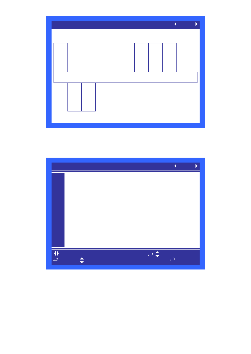
Liebert iCOM® Control
Liebert® CRV™92
Figure 85 Rack Overview, Page 1
This screen shows the rack label assigned to each rack and the temperature associated with the rack
sensor. This screen shows the relative distance between the Liebert CRV and each rack sensor.
Figure 86 Rack Setup, Page 1
Rack Sensors are automatically detected when connected and set to “Control.” A maximum of 10
2T sensors can be connected; the control automatically detects the type.
Control—The Liebert CRV is using the sensor for temperature control.
Reference—The sensor value is shown, but not used for temperature control.
Disable—No sensor connected.
Rack Overview (page 1 of 1) UNIT 01
All temperatures shown in °F
Cold Aisle
1
77
CC21
2
78
BB01
3
78
BB02
4
77
BB03
78
EC50
5
EC51
6
to change parameter
for next/previous unit to select parameter
to confirm
then
S901
S902
S903
S904
S905
S906
S907
S908
S909
S910
S911
PASSWORD Actual Level 0) ????
Remote Sensor Node 01 Control
Remote Sensor Node 02 Control
Remote Sensor Node 03 Control
Remote Sensor Node 04 Control
Remote Sensor Node 05 Control
Remote Sensor Node 06 Control
Remote Sensor Node 07 Disable
Remote Sensor Node 08 Disable
Remote Sensor Node 09 Disable
Remote Sensor Node 10 Disable
RACK SETUP (page 1 of 3) UNIT 01
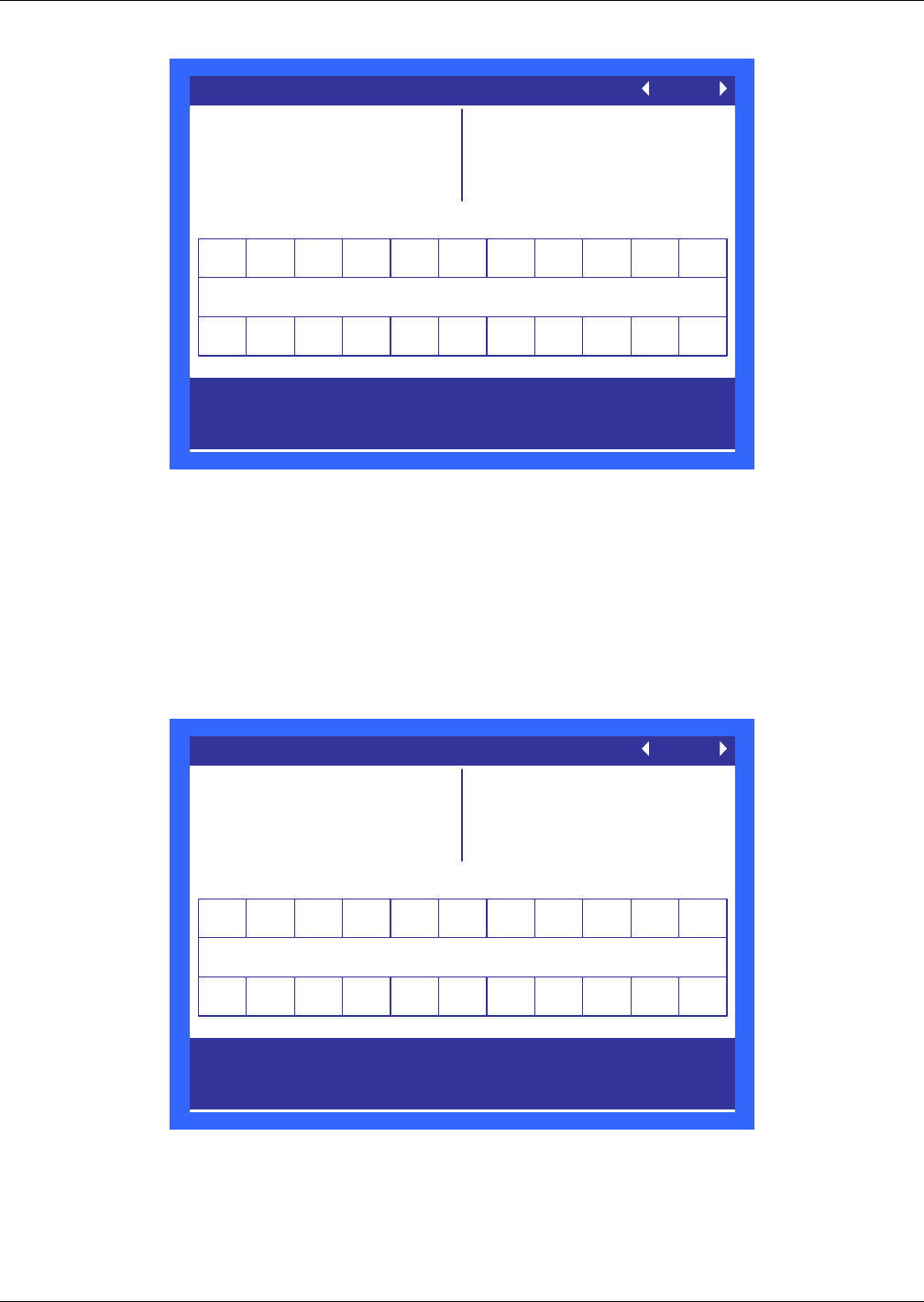
Liebert iCOM® Control
93 Liebert® CRV™
Figure 87 Rack Setup, Page 2
The Rack Setup display allows creating a graphical map of the remote rack sensors.
When the Assigned Sensors 1-6 are selected, it will drop the user down to assign the sensor node
address to the first group of six “boxes.” Setting “CRV” instead of a number (CRV is located below 0)
will give the hard-coded name “CRV” to the selected box.
A sensor address (#1- #10) or “CRV” can be assigned only once per screen.
The names for each rack can be assigned on the next page. Once names have been assigned, they will
also show up on this page (read only).
Figure 88 Rack Setup, Page 3
The Rack Setup display allows naming each rack with up to four characters, either letters or digits
(A-Z or 0-9). Names can be assigned to each rack except those that have no sensor (#0-#10), no “CRV”
or “Rack w/o sensor (-2)” assigned on the previous Rack Setup page.
When the Assigned Names 1-6 are selected, it will drop the user down to assign the rack name to the
first group of six “boxes.”
Use the navigation keys to move from rack to rack.
Enter to select a rack, and up - or down keys to scroll through
options .
RACK SETUP (page 2 of 3) UNIT 01
Liebert CRV = CRV
No Sensors = -2
No Rack = 0
Sensor Node = 01-10
Assign Sensors: 01-06
07-12
13-18
19-22
Cold Aisle
10000002340
05600000000
CC21
Use the navigation keys to move from rack to rack.
Enter to select a rack, and up - or down keys to scroll through
options .
RACK SETUP (page 3 of 3) UNIT 01
Liebert CRV = CRV
No Sensors = -2
No Rack = 0
Sensor Node = 01-10
Assign Sensors: 01-06
07-12
13-18
19-22
Cold Aisle
10000002340
05600000000
EC50 EC51
CC21 BB01 BB02BB03

Liebert iCOM® Control
Liebert® CRV™94
Figure 89 Options setup parameters - Page 1
Low Pressure Alarm Delay—This parameter sets the amount of time that the unit will ignore a
low pressure condition. In the past this parameter has also been referred to as a Winter Start Time.
This parameter can be set between 0 to 5 minutes.
Electric Stages—This parameter shows the number of electric stages that can be activated during a
call for reheat. This parameter is setup from the factory based on the model number of the unit.
3P Actuator Runtime—If Valve Control is selected for “Time” then this parameter sets the travel
time of the valve to determine the full open and closed position of the valve. This setting is set from
the factory based on the valves manufacturer specifications.
3P Actuator Direction—This parameter selects if the valve is a “Direct” or “Reverse” acting valve.
Note
NOTE
When attaching the optional leak detection sensors (Liebert Liqui-tect®) the following
parameters must be adjusted:
• S408 – Set to LQTECH
• S409 – Set to alarm
to change parameter
for next/previous unit to select parameter
to confirm
then
S401
S402
S403
S404
S405
S406
S407
S408
S409
S410
S411
PASSWORD Actual Level 0) ????
Low Pressure Alarm Delay 1min
Electric Stages 1
Heater ON at CFC -66 %
Water Detector No
Water Detector Function
3P Actuator Runtime sec
3P Actuator Direction
OPTIONS SETUP (page 1 of 2) UNIT 01

Liebert iCOM® Control
95 Liebert® CRV™
Figure 90 Options setup parameters - Page 2
WA and AL Relay—
Dehumidification Enabled—This parameters selects if the compressor and / or valve will be used
to dehumidify when the humidity is above setpoint.
Auto Restart Enabled—This parameter when set to “Yes” restarts the unit after a power cycle.
When this parameter is set to “No” then the unit will not restart (Turn On) after a power cycle.
Single Unit Auto Restart—This parameter sets a time delay for the unit to restart when the Auto
Restart Enabled is set to “Yes”. The delay begins once the boot process has completed. This parameter
allows units to be staggered On to reduce the amount of simultaneous power consumption after a loss
of power.
On-Off Enabled—This parameter disables the power button on the front of the display. The default
configuration is “On”.
to change parameter
for next/previous unit to select parameter
to confirm
then
S412
S413
S414
S415
S416
S417
S418
S419
S420
S421
S422
PASSWORD Actual Level 0) ????
WA and AL Relay Direct
Dehumidification Enabled Yes
Auto Restart Enabled Yes
Single Unit Auto Restart 5sec
On-Off Enabled Yes
OPTIONS SETUP (page 2 of 2) UNIT 01
Liebert iCOM® Control
Liebert® CRV™96
Table 27 Service contact info parameters
Function Range
Imperial (metric)
Large Display Small Display
Page 1 of 1
Password PASSWORD -
Country Country
None
Austria
Switzerland D
Switzerland F
Benelux D
Benelux FL
Germany
France
UK
Hungary
Italy
Poland
Spain
United States
Australia
New Zealand
Indonesia
Malaysia
Singapore
Address line 1 Address line 1 text-string
Address line 2 Address line 2 text-string
Address line 3 Address line 3 text-string
Address line 4 Address line 4 text-string

Operation in Teamwork Mode
97 Liebert® CRV™
11.0 OPERATION IN TEAMWORK MODE
11.1 Unit-to-Unit Network Wiring
Liebert CRV’s can be connected in a unit-to-unit, or U2U, configuration, which allows multiple units
to communicate with each other, sharing of local unit status and sensor readings. The U2U network
will allow up to 32 units to be connected within a single group and up to 99 different groups to exists
on the same physical network. Groups can be used to create zones of influence so that only the Liebert
CRV’s serving a common area will work together and back each other up.
The U2U setup unlocks the use of Lead-Lag/Rotation, Cascade and Teamwork Modes 1 and 2.
Lead-lag/rotation allows a standby Liebert CRV to activate based on an alarm or on a rotation
based on time.
Cascade provides staging of the Liebert CRV’s based on the actual temperature and its relation to
the temperature setpoint.
Teamwork Modes 1 and 2 use the collective temperature information from all Liebert CRV’s on the
U2U network within the same group to determine how the group of Liebert CRV’s should operate. To
help manage the large amount of sensor information Liebert iCOM® allows the sensor data to be used
as an average or a maximum value of all temperature sensor readings at both the local and system
level.
Different groups can be configured to operation in different teamwork modes. If one Liebert CRV
group serves a nonbalanced load, Teamwork Mode 2 will share all sensor data, prevent conflicting
modes of operation between units but still allow each Liebert CRV to modulate based on the unit’s
local sensor readings. Another group of Liebert CRV’s can be configured to operate in Teamwork
Mode 1 that will share all sensor data, prevent conflicting modes of operation between units but will
modulate all Liebert CRV’s at the same capacity based on the U2U sensor readings.
11.2 Liebert iCOM U2U Ethernet Network
The Liebert iCOM U2U network must be isolated from other network traffic. The network switch(es)
that connect Liebert iCOM controls must be dedicated to supporting only Liebert iCOM
communication. The U2U network cannot be connected to the building or IT network. If network
communication is ever lost, all Liebert iCOM-controlled cooling units will continue to operate as
independent units.
The Liebert iCOM control can support up to 64 nodes on one network. An input/output board, large
display and large wall-mount display are each considered one node. Of the 64 nodes that may be
connected, no more than 32 may be input/output boards (32 cooling units).
Network communication can be configured during system startup by a Liebert-trained technician. For
technical issues contact:
Liebert Technical Service
1050 Dearborn Drive
Columbus, Ohio 43235
Telephone: 1-800-LIEBSRV (1-800-543-2778)
E-Mail: technicalservice@emersonnetworkpower.com
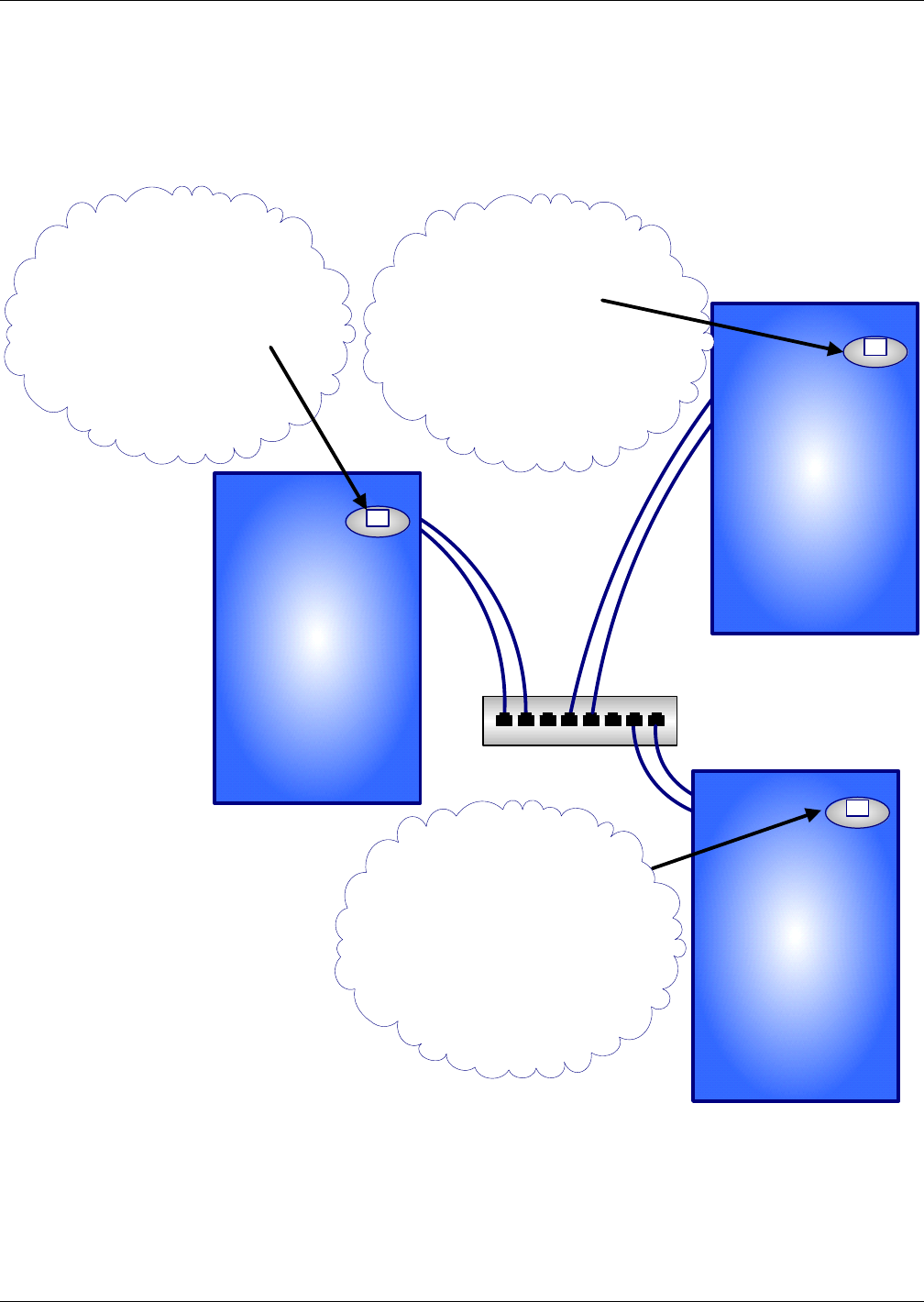
Operation in Teamwork Mode
Liebert® CRV™98
11.3 Wiring a Liebert iCOM® U2U Network
A network switch is required to enable Ethernet unit-to-unit communication on one or more Liebert
CRV’s. Each Liebert CRV requires two straight-through Ethernet cables from a network switch. One
cable connects to port P64 on the Liebert iCOM input/output board and the other straight-through
cable connects to the P64 port on the back of the large display (see Figure 92).
Figure 91 U2U network setup diagram
Network
Switch
Liebert Cooling Unit
with Large Liebert
iCOM Display
Liebert Cooling Unit
with Large Liebert
iCOM Display
Liebert Cooling Unit
with Large Liebert
iCOM Display
Display Service/Network
Liebert iCom Display Menu
IP Address: 192.168.254.033
U2U Address: 33
Group #: 1
---------------------------------------
Display Service/Network
Liebert Cooling Unit
Control Board Menu
IP Address: 192.168.254.001
U2U Address: 1
Group #: 1
Display Service/Network
Liebert iCom Display Menu
IP Address: 192.168.254.034
U2U Address: 34
Group #: 1
---------------------------------------
Display Service/Network
Liebert Cooling Unit
Control Board Menu
IP Address: 192.168.254.002
U2U Address: 2
Group #: 1
Display Service/Network
Liebert iCom Display Menu
IP Address: 192.168.254.035
U2U Address: 35
Group #: 1
---------------------------------------
Display Service/Network
Liebert Cooling Unit
Control Board Menu
IP Address: 192.168.254.003
U2U Address: 3
Group #: 1
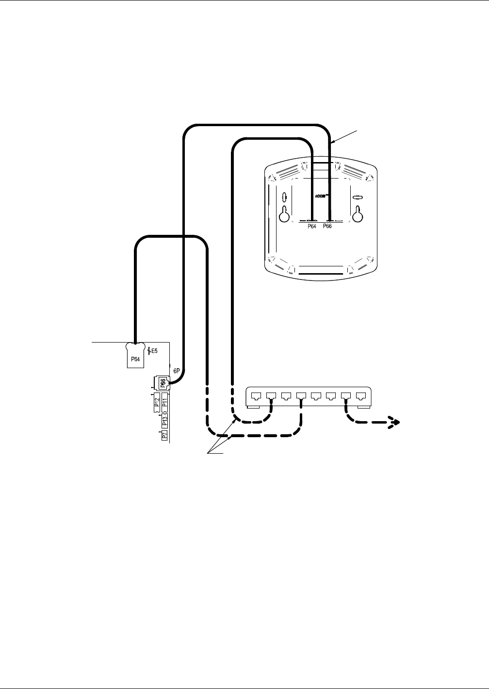
Operation in Teamwork Mode
99 Liebert® CRV™
Wall-Mount Large Display
The Liebert CRV has a large display as standard equipment. Only large displays can be used for
remotely monitoring and controlling cooling units connected on the same network. Each wall-mount
large display requires 120V input power; Liebert provides an AC adapter wall plug. A straight-
through Ethernet cable must be connected between the network switch and the P64 port on the back
of the display. This will enable control and monitoring capabilities to any cooling unit connected to the
network.
Figure 92 Wiring a large display for U2U network operation
11.4 Teamwork Modes
Groups of cooling units connected to a network can be set up to work together in any of three
teamwork modes:
•No Teamwork
• Teamwork Mode 1
• Teamwork Mode 2
All Liebert iCOM-controlled cooling units on a network must be set to run in the same teamwork
mode.
Liebert iCOM
I/O Board
Straight-Through
Ethernet Cables
CAN
Cable
See Note 4
Large Graphics Display
(Rear View)
To / From Other
Networked Units
U2U Networking Switch
(Field-Supplied)
194273
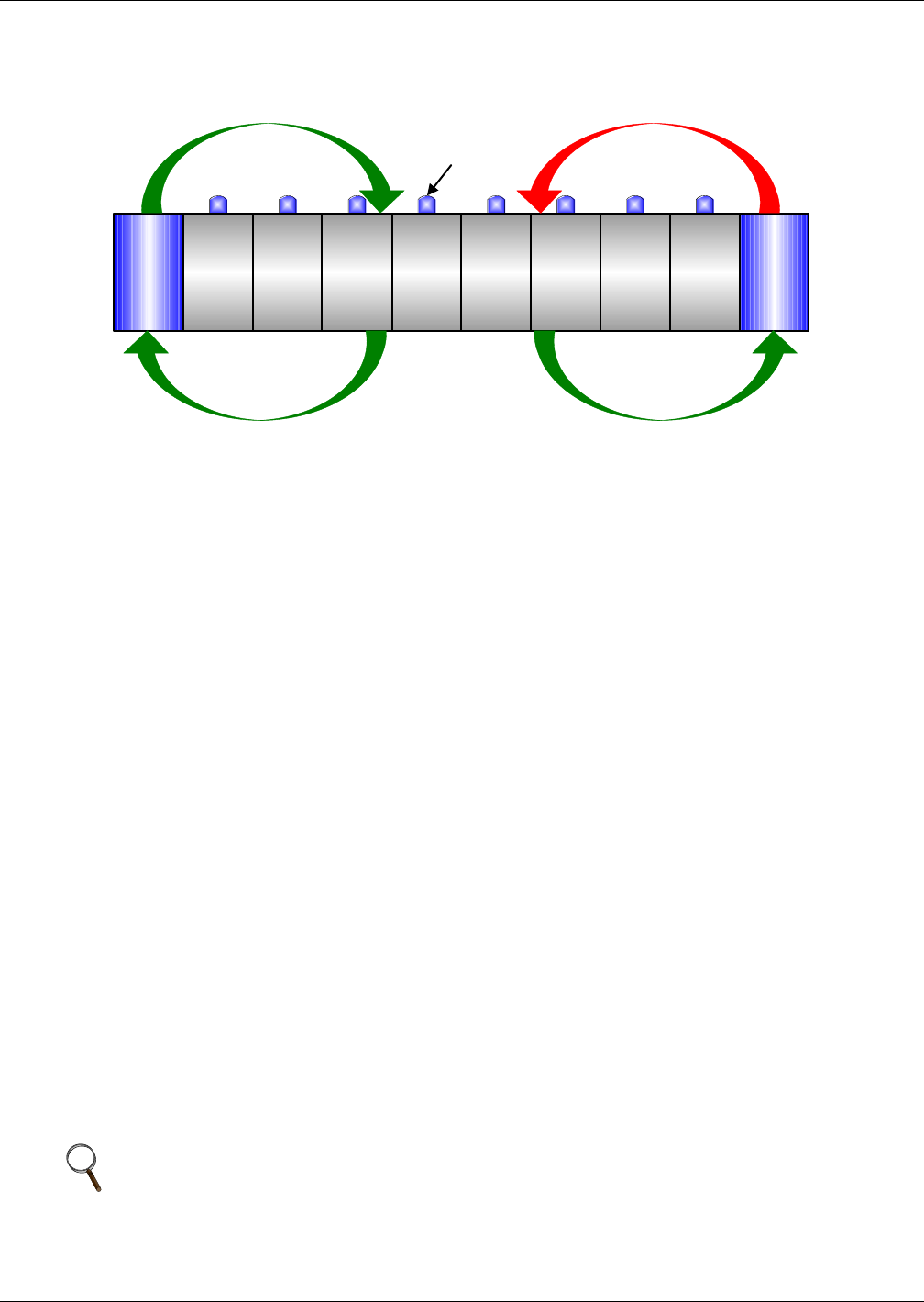
Operation in Teamwork Mode
Liebert® CRV™100
Figure 93 Teamwork modes and sensor management
11.4.1 Application of Teamwork Modes
•No Teamwork: Multiple zones in one room
•Teamwork Mode 1: Balanced load (small groups of units inside the same environment)
•Teamwork Mode 2: Unbalanced load (large rooms, not all units will have the same load) (work
well for most applications)
All units in a network will run in the same Teamwork Mode.
11.4.2 No Teamwork
All cooling units work independently, responding to their own sensors.
Standby function and unit rotation are possible, but cascading is not (see Standby and Cascade on
page 102). AutoSet will not adjust the proportional band in this mode.
11.4.3 Teamwork Mode 1
Teamwork Mode 1 works best in small rooms with balanced heat loads. The return temperature and
humidity sensor readings of all units in operation (fan on) are averaged by the master unit, Unit #1,
and used for control. The master unit will send the operating requirements to all operating units
according to unit numbers, rotated by one unit every 24 hours.
In this teamwork mode, most of the parameters are shared; if set in any one of the units, all other
units will follow with the same settings. AutoSet will adjust the proportional band in Teamwork
Mode 1.
The master unit evenly divides the system proportional band among the number of available units.
Each unit will receive instruction on how to operate from the master unit based on how far the system
deviates from the setpoints.
The number of available units is calculated like:
• In non-standby configuration: all units with fan on
• In typical standby function (no cascade): all units with fan on
• In cascade mode: all units that could operate (no alarm, which forces the unit to switch off, unit
not switched off, etc.)
NOTE
1. Proportional actuators (chilled water valve, free-cooling actuator) are driven in parallel in
all units.
2. Changeover to second cooling source, low limit during dehumidification and low supply
limit control air local functions, managed from each unit independently.
Liebert CRV 1
Max = 72°F (22°C)
Liebert CRV 2
Max = 76°F (24°C)
Liebert
CRV 1
Liebert
CRV 2
Equipment
Rack
Equipment
Rack
Equipment
Rack
Equipment
Rack
Equipment
Rack
Equipment
Rack
Equipment
Rack
Equipment
Rack
Teamwork Sensor Average = 74°F (23°C)
Teamwork Sensor Maximum = 76°F (24°C)
Average / Maximum of Liebert CRV Connected Sensors
Average / Maximum of Teamwork Sensors
Example: 72°F (22°C) Setpoint
Sensor
(one of 8)
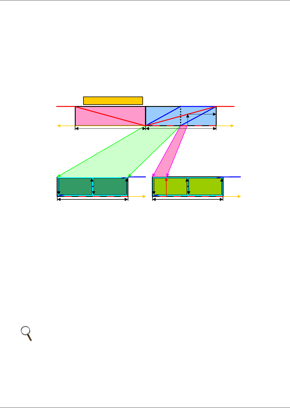
Operation in Teamwork Mode
101 Liebert® CRV™
Figure 94 shows how two cooling units work together in Teamwork Mode 1. Since Unit 1 and Unit 2
are available to operate, the master unit, Unit 1, averages the temperature and humidity sensor
readings from each unit.
The master unit determines that a 60% call for cooling is required for the system. Since there are two
available cooling units, each unit makes up half of the system proportional band; Unit 1 handles 0-
50% system call for cooling and Unit 2 handles 51-100%. For every 1% system call for cooling, each
unit provides 2% of its total cooling capacity.
The 60% system call for cooling exceeds the 50% Unit 1 can provide, so Unit 1 operates at full
capacity. The remaining 10% system call for cooling (60% - 50% = 10%) is handled by Unit 2. Unit 2
responds by operating at 20% cooling capacity (50% ÷ 10% = 20%).
Figure 94 Teamwork Mode 1 with two cooling units
11.4.4 Teamwork Mode 2
Teamwork Mode 2 is designed to prevent units within a group from working against each other or
“fighting.” It is best applied in large rooms with unbalanced heat loads. In Teamwork Mode 2, all
parameters are shared equal to Mode 1, and Unit #1 averages all of the available unit sensor readings
on the network to define whether there is a cooling, heating, dehumidification or humidification
request.
If there is a cooling request, all units are released to start cooling resources according to their own
temperature readings; heating is disabled for all units and vice versa. Same for humidity control.
If the network average would ask for 0% proportional band, the most demanding request (highest or
lowest temperature of all units, highest or lowest humidity of all units) would be used to define the
operation to be performed.
Teamwork Mode 2 does not rotate; unevenly distributed working hours to be expected. AutoSet will
not adjust the proportional band in this mode.
NOTE
In Teamwork Mode 2, all units must have the same setpoints. The units’ proportional band,
deadband and related settings may differ.
C1 C2
cooling
+100 %
0% 1 /2 Pr oportional Band
+temp.
Unit 2 Deviation : 20 %
Setpoint
C1 C2
cooling
+ 100 %
0% 1/2 Proportional Band
+temp.
Setpoint
0%
Setpoint
- tem p.
-100 %
+tem p .
1 /2 Pr oportional Band +100 %
1 /2 Pr opor tional Band
heating
100 %
60 %
0%
System Deviat ion : 60%
System proportional band
Unit 1 D eviation : 100 %

Operation in Teamwork Mode
Liebert® CRV™102
11.4.5 Standby—Rotation
Typical Standby (Lead/Lag) Function
This function can be performed in any teamwork mode, including NO Teamwork.
One or more units can be defined to be Standby; the normal status of standby units is Standby Off
(fan off).
In case one regular unit has an alarm that is defined (to be defined in the alarm configuration), to
switch on a standby unit, the faulty unit will switch off and the standby unit will switch on.
If the next unit has an alarm, the next standby unit will be started. If no more standby units are
available, the unit with a non-critical alarm that permits unit operation will be switched on again
(water detection, fan alarm, fire alarm etc. will not permit unit restarting).
The standby function can be rotated daily (setting the time), weekly (setting the day of the week and
time) or monthly (setting the first weekday of the month and time).
The rotation is performed with a selectable number of units: if 1 is selected, to standby rotates from
1-2 to 2-3 in a 4 units configuration with two standby units, and rotates from 1-2 to 3-4 in the same
configuration, when the rotation parameter is set to 2.
Standby and Cascade
Cascade is possible in Teamwork Mode 1 only.
Standby units will start if an alarm occurs in one of the operational units. If the standby units are
cascaded, they will also start and work with the regular operational units if the temperature or
humidity cannot be controlled by the operational units; before a high or low temperature / humidity
condition occurs. Cascaded units are switched off again as soon as the temperature / humidity returns
back to normal.
The master unit defines its proportional band according to the number of available units (see
11.4.3 Teamwork Mode 1).
When a standby unit receives a request for full heating or cooling from the master unit, it will
respond to the request after its control delay.
NOTE
Before entering standby mode, units will operate the fan only for 3 minutes to cool the electrical
heaters, remove steam from the unit, etc.
NOTE
Cascaded units are not included in the calculation of the average temperature / humidity.
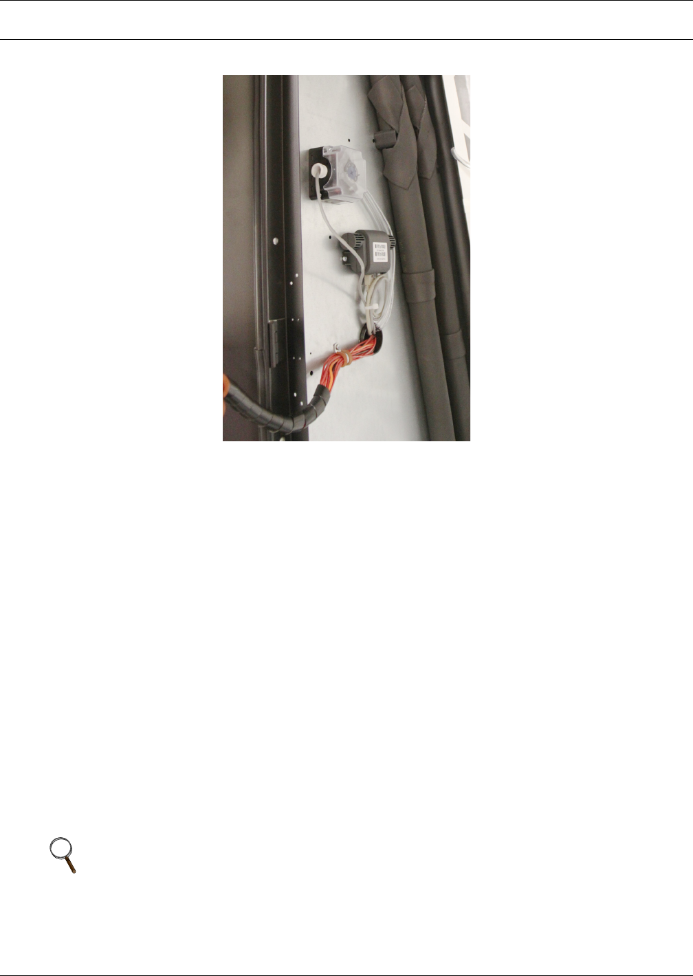
Operation
103 Liebert® CRV™
12.0 OPERATION
Figure 95 Return air temperature and humidity sensor viewed from the rear of the unit
The control system compares the relayed information with the programmed setpoint and proportional
band values and performs one of the following operations:
•Cooling—Direct expansion mode (DX): The compressor is started and the cold refrigerant flows
through the evaporator, thus cooling the air passing through it. For compressor operation see
Liebert iCOM® user manual, SL-18835. Liebert recommends using the supply temperature sensor
to control the cooling capacity of the Liebert CRV, but cooling can be managed from any of the
temperature sensors. The supply temperature is an accurate representation of the actual heat
rejection the Liebert CRV needs to perform. Chilled water Liebert CRV models will modulate the
cooling capacity from 0% - 100% and DX models will modulate the cooling capacity from 20% -
100% compressor capacity. To avoid short-cycling the compressor during room heat load changes,
the CRV will not deactivate the compressor until the air temperature is below 150% of tempera-
ture setpoint when in Remote or Supply Air Control or below 200% of temperature setpoint when
operating in Return Air Control.
•Chilled water mode (CW)—The three-way valve is opened and the chilled water flows through
the coil, thus cooling the air passing through it. For valve operation, see the Liebert iCOM user
manual, SL-18835.
•Reheating—Electrical heating (optional): The heating elements heat the air passing over them
during dehumidifcation. The heating control is active only when the unit is in dehumidification
mode. The reheats will only activate when the unit is dehumidifying. The reheats will begin acti-
vation when the control temperature has dropped to -66% of the control’s proportional band and
will deactivate when temperature setpoint has been reached.
•Dehumidification (DX mode)— The temperature of the cooling coil is reduced to remove mois-
ture from the air (refer to Figures 58,59,69 and 90).
In dehumidification mode, the air after passing over the coil is reheated (if needed) by electrical
heaters to stabilize the initial temperature.
NOTE
If dehumidification cannot reach its setpoint within a set amount of time, the unit will delay
dehumidification to allow the room temperature to stabilize.

Operation
Liebert® CRV™104
•Humidification (optional)—The humidifier creates steam, which is distributed into the air
stream via the steam distribution pipe. (See also Appendix A - Humidifier). The Liebert CRV’s
humidification is activated when the measured temperature and humidity sensor has been calcu-
lated to exceed the corresponding dew point setpoint. The dew point setpoint is calculated based
on the temperature and humidity of the sensor set to control the control setpoint and relative
humidity.
Example: Temperature Setpoint 72°F / Humidity Setpoint 50% = 52°F Dew Point
NOTE
The Liebert iCOM® control monitors the condition of the air discharging from the unit to
protect neighboring electronic equipment. Liebert iCOM will prevent the humidifier from
activating if the discharge air is near its saturation point. This protects against discharging fog
from the unit or condensation forming on the unit's supply air baffles. This protection mode is
activated when the supply sensor reading is below 53°F (11.7°C) or above 55% relative
humidity. When this condition is met a message will display showing “humidifier” suspended.
The status of the humidifier lockout can be viewed in the Service/Diagnostics menu.
These protections do not apply to the external humidifier output.

Operation
105 Liebert® CRV™
12.1 Alarms/Events
The following alarms and events are supported by the Liebert iCOM® control on the Liebert CRV.
When an alarm is triggered the alarm sounds, the LED will flash red, an event will be written to the
Event Log and the BMS will be notified. If the alarm is acknowledged, the alarm will silence and the
LED will turn solid red. When the alarm condition is resolved, the LED lights green and the BMS
alarm notification is reset.
General Alarm Unit 07 Disconnected Dig Scroll1 High Temp Unit 31 Disconnected
Comp 1 High Pressure Unit 08 Disconnected Smoke Detected Unit 32 Disconnected
Comp 1 Low Pressure Unit 09 Disconnected Water Under Floor System Off Requested
High CW Temp Unit 10 Disconnected Cond Pump-High Water System Off Confirmed
Loss of CW Flow Unit 11 Disconnected Loss of Flow Fire Alarm
Loss of Airflow Unit 12 Disconnected El Heat1 Hrs Exceeded Heaters Overheated
Clogged Filters Unit 13 Disconnected Unit Code Missing Condenser 1 Failure
Customer Input 1 Unit 14 Disconnected Loss of Power Humidifier Cylinder Worn
Customer Input 2 Unit 15 Disconnected Reheat Lockout Maintenance Done
Customer Input 3 Unit 16 Disconnected Heat Rej VFD Maintenance to be Done!
Customer Input 4 Dscroll 1 Sensor Fail Humidifier Lockout Top Fan Failure
LP Transducer 1 Fail On-Off Key Disabled Heat Rej TVSS Control Valve Failure
Call Service Lwd Sensor Fail Compressor(S) Lockout Fluid Sensor Failure
High Temperature Hum Disabled Humidifier Low Amps High Supply Temperature
Unit Hrs Exceeded Hum Enabled Comp 1 Short Cycle Low Supply Temperature
Comp 1 Hrs Exceeded RAM / Battery Fail Humidifier High Amps High Return Humidity
Hum Hrs Exceeded Low Memory 1 Humidifier Low Water Low Return Humidity
Supply Sensor Failure No Connection w/Unit1 Unit 17 Disconnected Rack Sensor 1 Failure
Room Sensor Failure Hp Transducer 1 Fail Unit 18 Disconnected Rack Sensor 2 Failure
Network Failure Comp Power Reduction Unit 19 Disconnected Rack Sensor 3 Failure
Unit On No Power Unit 20 Disconnected Rack Sensor 4 Failure
Unit Off Unit Disabled Unit 21 Disconnected Rack Sensor 5 Failure
Standby Mode Unit Shut Down Unit 22 Disconnected Rack Sensor 6 Failure
Power On Dehum Disabled Unit 23 Disconnected Rack Sensor 7 Failure
Power Off Dehum Disabled 12hrs Unit 24 Disconnected Rack Sensor 8 Failure
Unit 01 Disconnected Dehum Enabled Unit 25 Disconnected Rack Sensor 9 Failure
Unit 02 Disconnected Humidifier Problem Unit 26 Disconnected Rack Sensor 10 Failure
Unit 03 Disconnected Dehum Hrs Exceeded Unit 27 Disconnected High Return Temperature
Unit 04 Disconnected Comp 1 Pumpdown Fail Unit 28 Disconnected Room Humidity Problem
Unit 05 Disconnected HCB Not Connected Unit 29 Disconnected Bottom Fan Failure
Unit 06 Disconnected BMS Disconnected Unit 30 Disconnected

Calibration and Regulation after Startup
Liebert® CRV™106
13.0 CALIBRATION AND REGULATION AFTER STARTUP
The Liebert CRV has been factory-tested and calibrated, but it is very important to check, at startup,
the superheating of the thermostatic valve (A/W versions).
• For calibrations of instruments installed on the external condensers/drycoolers, refer to the man-
ual for the equipment.
• For control system calibrations, refer to the Liebert iCOM® manual, SL-18835. (To prevent erratic
operation, do not use temperature and relative humidity setpoints/proportional bands that differ
excessively from the default settings.)
13.1 Thermostatic Expansion Valve
The Thermostatic Expansion Valve (TEV) performs one function: It keeps the evaporator supplied
with enough refrigerant to satisfy load conditions. It does not effect compressor operation.
Proper valve operation can be determined by measuring superheat. The correct superheat setting is
between 10 and 20°F (-12 and -6°C). If too little refrigerant is being fed to the evaporator, the
superheat will be high; if too much refrigerant is being supplied, the superheat will be low.
13.1.1 Determine Suction Superheat
To determine superheat:
1. Measure the temperature of the suction line at the point the TEV bulb is clamped.
2. Obtain the gauge pressure at the compressor suction valve.
3. Add the estimated pressure drop between the bulb’s location and the suction valve.
4. Convert the sum of the two pressures to the equivalent temperature.
5. Subtract this temperature from the actual suction line temperature. The difference is superheat.
13.1.2 Adjust Superheat Setting with the TEV
To adjust the superheat setting:
1. Remove the valve cap at the bottom of the valve.
2. Turn the adjusting stem counterclockwise to lower the superheat.
3. Turn the adjusting stem clockwise to increase the superheat.
13.2 Environmental Protection
Misuse or incorrect calibration of the unit leads to increased energy consumption, resulting in
economic and environmental damage.
NOTE
Make no more than one turn of the stem at a time. As long as thirty minutes may be required
for the new balance to take place.
Maintenance
107 Liebert® CRV™
14.0 MAINTENANCE
14.1 Safety Instructions
All maintenance operations must strictly observe national, state and local accident prevention
regulations, especially the regulations concerning electrical systems, refrigerators and manufacturing
resources.
Air conditioning equipment maintenance may be performed only by authorized properly trained and
qualified personnel.
To keep all warranties valid, the maintenance must adhere to the manufacturer’s regulations.
NOTICE
Risk of improper maintenance. Can cause equipment damage.
All maintenance must be performed only by authorized properly trained and qualified
personnel.
Ignoring safety instructions can be dangerous to persons as well as to the environment. Soiled parts
always cause a loss of performance and, for switch or control devices, can lead to the breakdown of a
plant.
!
WARNING
Arc flash and electric shock hazard. Can cause injury and death.
Disconnect local and remote power supplies and wear appropriate personal protective
equipment per NFPA 70E before working within.
Before proceeding with installation, read all instructions, verify that all the parts are included
and check the nameplate to be sure the voltage matches available utility power.
The Liebert iCOM® microprocessor does not isolate power from the unit, even in the Unit Off
mode.
Some internal components require and receive power even during the Unit Off mode of the
Liebert iCOM control.
The factory-supplied optional disconnect switch is inside the unit. The line side of this switch
contains live hazardous voltage potential.
Install and open a remote disconnect switch and verify with a voltmeter that live hazardous
voltage potential is not present inside the unit cabinet before working within. Refer to the
unit electrical schematic.
Follow all national and local codes.
!
WARNING
Risk of contact with rotating fan blades and extremely hot and/or cold surfaces. Can cause
equipment damage, injury and death.
Disconnect all local and remote electric power supplies before working within. Perform
maintenance only when the system is de-energized, all fan blades have stopped rotating and
component temperatures have become safe for human contact.
• Turn Off the system by switching it Off at the controller and the main disconnect switch.
• Post a warning sign saying “Do not switch on.”
• Electrical components of the unit must be switched Off and checked using a voltmeter to
ensure they are not receiving electrical input power.
!
WARNING
Risk of hair, clothing and jewelry entanglement with high speed rotating fan blades. Can
cause equipment damage, serious injury or death.
Keep hair, jewelry and loose clothing secured and away from rotating fan blades during
operation.
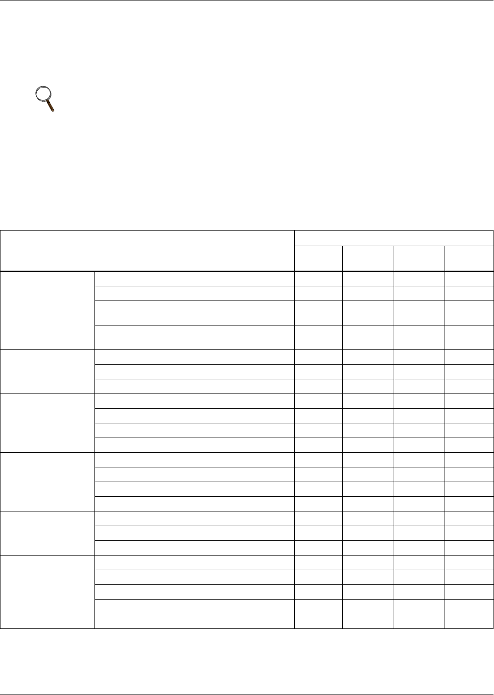
Maintenance
Liebert® CRV™108
14.2 Spare Parts
Only original spare parts made by Emerson Network Power may be used. Using third-party material
can invalidate the warranty. When making seeking technical assistance, always refer to the
component list supplied with the equipment, and specify the model number, serial number and, if
available, the part number.
14.3 Maintenance Schedule
Conduct monthly, quarterly, biannual and annual checks according to the following guidelines.
All tasks and time periods listed here are the manufacturers’ regulations and must be documented in
an inspection report.
NOTE
1. When replacing a faulty component, follow the relevant manufacturer instructions.
2. When the spare parts must be brazed, be careful not to damage the internal parts (gaskets,
seals, O-rings, etc.).
Table 28 Maintenance schedule
Component
Maintenance Period
Monthly
By User
Every
3 Months
Every
6 Months Annually
General
Check unit display for clogged-filter warning X
Check for irregular noise from unit fans X
Check for irregular noise from compressor (if
applicable) X
Check for irregular noise from remote
condenser fan(s) (if applicable) X
Filters
Check state of filters X
Replace air filter if necessary X
Check filter switch functionality X
Blowers
Verify impellers move freely X
Check bearings X
Check motor mounts for tightness X
Check fan safety switch X
Electrical/Electronics
Check condition of contacts X
Check electrical connections X
Check operation of controller X
Check unit operation sequence X
Steam-Generating
Humidifier
Check cylinder and pan X
Check condition of steam hoses X
Verify filling solenoid valve is operating properly X
Cooling Water Circuit
(Water/Glycol and
Chilled Water Units)
Check circuit for leakage/general condition X
Check water (glycol) inlet temperature X
Check water regulating valve operation X
Check in/out water (glycol)
Δ
tX
Check mixture glycol level (if applicable) X
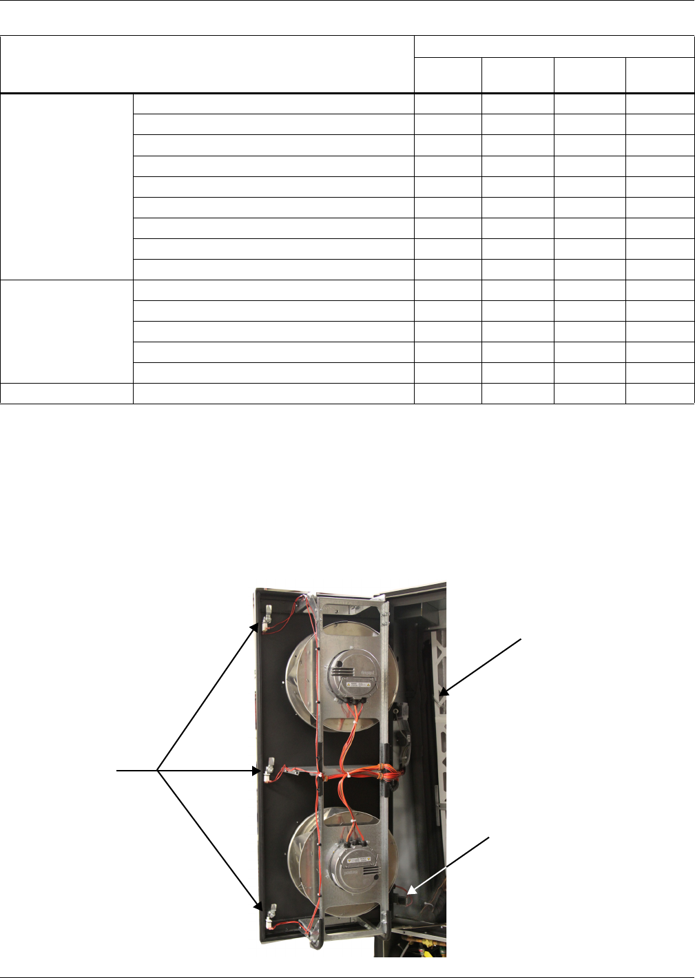
Maintenance
109 Liebert® CRV™
14.4 Inspect and Replace the Air Filter
Check the air filter monthly to maintain efficient air distribution through the evaporator coil.
1. Switch Off the CRV.
2. Open the rear panel by rotating the three locks with a screwdriver.
3. Wait until the fans stop rotating. When you open the first lock, you also open a safety switch that
cuts the input power; see Figure 96 below.
Figure 96 Air filter location and input power safety switch
Refrigerating Circuit
Check compressor noise/vibrations X
Check oil level through compressor sight glass X
Adjust/tighten compressor/functional elements X
Check sight glass for problem detection X
Check starting/running amps X
Check refrigerating circuit main pressures X
Check compressor suction superheat X
Check discharge temperature X
Check subcooling X
Air-Cooled
Condenser/Drycooler
(if applicable)
Check fan bearings X
Check fan motor mounts for tightness X
Check coil condition X
Check pipeline supports X
Check fan speed controller operation X
Water/Glycol Pump See manual for the pump
Table 28 Maintenance schedule
Component
Maintenance Period
Monthly
By User
Every
3 Months
Every
6 Months Annually
Safety
Switches
Safety Switch
Air Filter
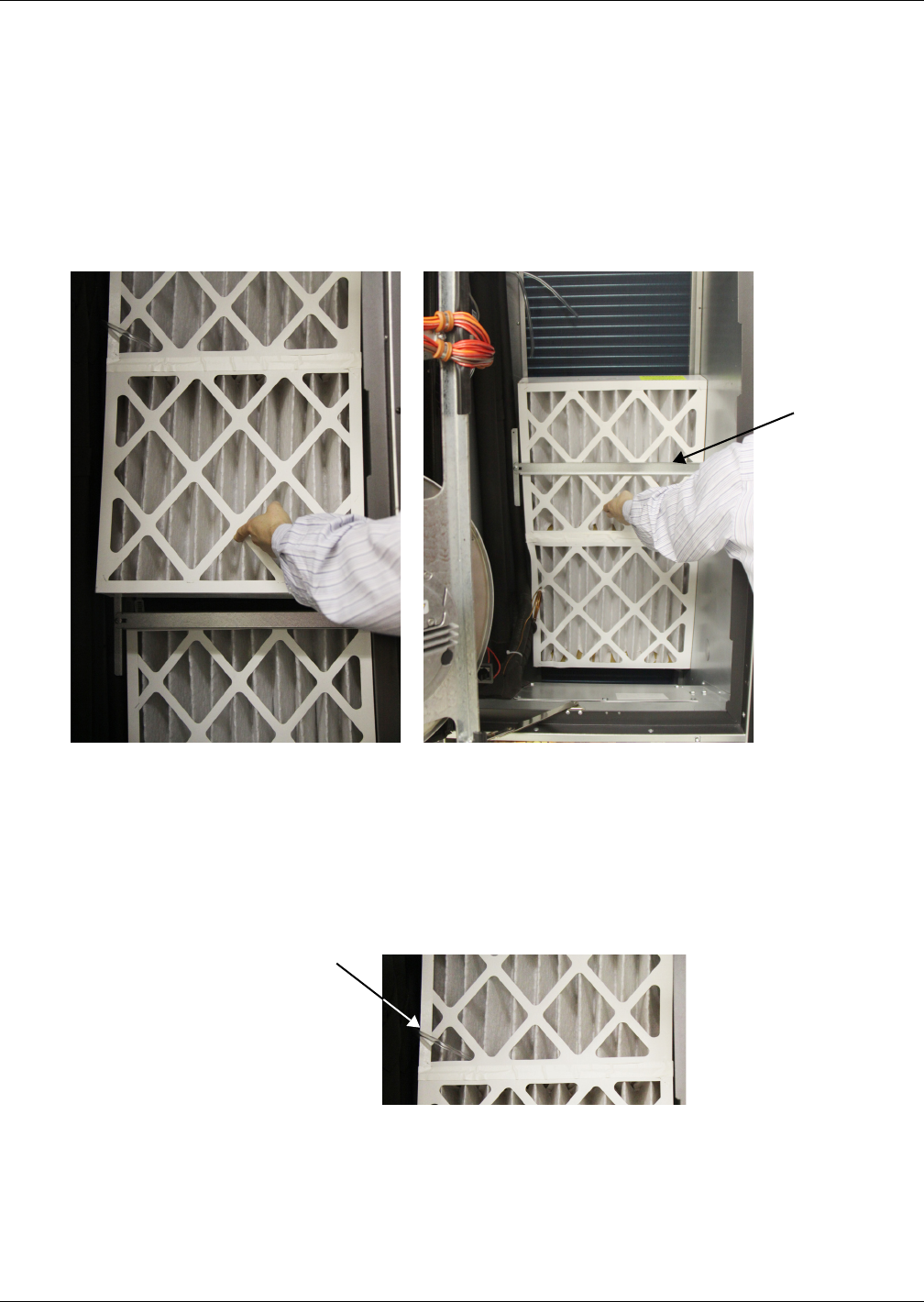
Maintenance
Liebert® CRV™110
To extract the filters (refer to Figure 97:
1. Push up the upper filter.
2. Pull the bottom of the filter away from the Liebert CRV.
3. Pull it out of the unit.
4. Lift the lower filter up
5. Pull the bottom of the filter away from the Liebert CRV.
6. Pull it out of the unit.
Figure 97 Remove the air filters
After cleaning or replacing the filter and before reassembling the unit, check that the air differential
pressure switch pipes (clogged filter alarm) are in the correct position and order. Check also that the
drain trays are clean and the pipe secure.
Figure 98 Differential pressure switch tubes
Before restarting the unit, be sure that the microswitches are properly closed; otherwise, the unit
remains in safety status.
Push the upper filter up, pull the
bottom away from the Liebert CRV and
lift it out of the unit
Slide the lower filter up beyond the support
bar and lift it out of the Liebert CRV the
same way as the upper filter
Upper Filter Lower Filter
Support Bar
Differential
pressure
switch tube
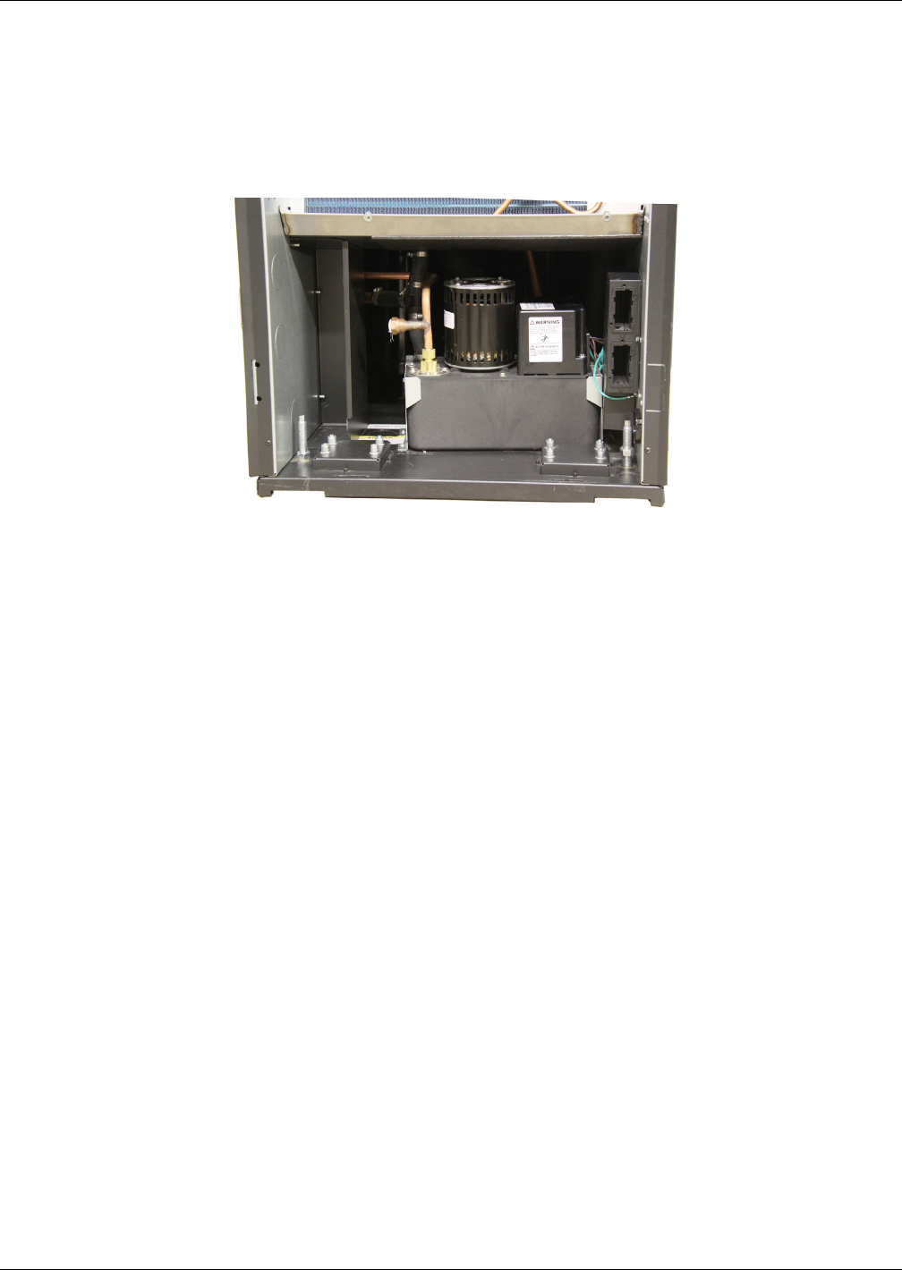
Maintenance
111 Liebert® CRV™
14.5 Condensate Drain and Condensate Pump Systems
14.5.1 Condensate drain
Check for and clear obstructions in tubing during routine maintenance.
14.5.2 Condensate Pump, Dual-Float
Figure 99 Condensate pump
1. Disconnect power to the unit using the disconnect switch.
2. Check for and clear obstructions in gravity lines leading to the condensate pump.
3. Remove the sump, clean with a stiff nylon brush and flush with water.
4. Inspect and clear clogs in the discharge check valve and float mechanism.
5. Reassemble and check for leaks.
14.6 Air-Cooled Condenser and Drycoolers
1. Clear the coil surface of all debris that might inhibit airflow.
2. Check for and correct bent or damaged coil fins.
3. Do not permit snow to accumulate around or under an outdoor unit.
4. Consider having the coil surface commercially cleaned periodically.
5. Inspect fans, motors and controls for proper operation.
6. Check all piping and capillaries for proper support.
7. Inspect for leaks.
14.7 Electrical Heaters
1. Inspect and clean reheat elements.
2. Inspect and tighten support hardware.

Maintenance
Liebert® CRV™112
14.8 Dismantling the Unit
The Liebert CRV has been designed and built to ensure continuous operation.
The working life of some of the main components, such as the fan and the compressor, depends on
proper maintenance.
NOTICE
Risk of release of hazardous substances into the environment. Can cause environmental
pollution and violation of environmental regulations.
The Liebert CRV contains substances and components hazardous for the environment
(electronic components, refrigerating gases and oils). At the end of its useful life, the
Liebert CRV must be dismantled by specialized refrigerating technicians. The unit must be
delivered to suitable centers specializing in the collection and disposal of equipment
containing hazardous substances.
The refrigerating fluid and the lubricating oil inside the circuit must be recovered according to the
laws in the relevant country.
To recover the gas, use all the connections described in 6.0 Refrigerant Connections.
14.9 F-Gas Regulation (EC) No. 842/2006
Stationary air conditioning placed in the European Community market and operating with
fluorinated greenhouse gases (F-gas), such as R-134A, R-407C and R-410A, must comply with the F-
gas Regulation (applied since July 4, 2007).
Following considerations must be observed when operating with the above-mentioned equipment:
• Fluorinated greenhouse gases are covered by the Kyoto Protocol.
• The fluorinated greenhouse gases in this equipment should not be vented to the atmosphere.
• Referring to the value noted in Annex I of Regulation (EC) No 842/2006, the following list speci-
fies the global warming potential (GWP) of some major F-gases:
• R-134A: GWP 1300
• R-407C: GWP 1610
• R-410A: GWP 1890
• Operators of the above-mentioned applications, which contain fluorinated greenhouse gases,
shall, using all measures that are technically feasible and do not entail disproportionate cost:
a. prevent leakage of these gases and, as soon as possible, repair any detected leakage;
b. ensure that they are checked for leakage by certified personnel;
c. ensure arrangements are put in place for the proper recovery by certified personnel.
d. In case of applications containing 3 kg (6 kg in case of hermetically sealed systems) or more of
F-gases, certified personnel and companies (according to Reg. 303/2008) provide regular leak
testing (according to Reg. 1516/2007 and Reg. 1497/2007) and maintain records of
maintenance activities in a dedicated log book.
e. Recovery for the purpose of recycling, reclamation or destruction of the fluorinated
greenhouse gases, pursuant to Art. 4 (Recovery) of Reg.842/2006, shall take place before the
final disposal of that equipment and, when appropriate, during its servicing and
maintenance.
• Operator, according to Reg. 842/2006, Article 2, point 6, means the natural or legal person exercis-
ing actual power over the technical functioning of the equipment and system covered by the Regu-
lation. The State may, in defined, specific situations, designate the owner as being responsible for
the operator's obligations.
• Direct methods of leakage checking approved by the manufacturer (Reg. 1516/2007 and Reg.
1497/2007):
a. gas detection device adapted to the refrigerant in the system; the sensitivity of portable gas
detection devices (as a direct test method) shall be at least five grams per year.
b. proprietary bubble solutions / soapsuds.

Maintenance
113 Liebert® CRV™
• Additional information located in a dedicated label of the unit (Reg. 1494/2007):
a. Where fluorinated greenhouse gas is foreseen to be added to the equipment outside of the
manufacturing site at the point of installation, a dedicated label accommodates notation of
both the quantity (kg) pre-charged in the manufacturing plant and the quantity charged at
the installation site, as well as the resulting total quantity of F-gas as a combination of the
above-mentioned quantities, in a manner that conforms to legibility and indelibility.
Our split units are usually not pre-charged at the factory; in this case, the total quantity of
refrigerant charged in the unit must be written in the relevant label, during the commission-
ing operation at the installation site.
b. Our packaged units (not split) operating with F-gas are usually fully charged at the factory,
and the total amount of refrigerant charge is already reported on the label. In this case, the
label has no need of further written information.
c. In general, the above-mentioned information has been located in the main nameplate of the
relevant unit.
d. For equipment with double refrigeration circuits, in regards to different requirements based
on the quantity of F-gas contained, the required information about refrigerant charge
quantities must be listed separately for each individual circuit.
e. For equipment with separate indoor and outdoor sections connected by refrigerant piping, the
label information will be on that part of the equipment that is initially charged with the
refrigerant. In case of a split system (separate indoor and outdoor sections) without a factory
precharge of refrigerant, the mandatory label information will be on that part of the product
or equipment that contains the most suitable service points for charging or recovering the
fluorinated greenhouse gas(es).
• Safety data sheets of F-gases used into the products are available on demand.

Troubleshooting
Liebert® CRV™114
15.0 TROUBLESHOOTING
Table 29 Unit diagnostics
Problem Possible Cause Corrective Action
Rack temperature
is too high
Dirty filters Replace filters
Filter clog sensor failure Call Emerson Network Power
Incorrect positioning of remote
temperature sensor(s)
Verify that remote temperature sensors are correctly
positioned
Remote temperature sensor(s) issue Contact Emerson
Condensing pressure (head pressure) is
too high
Air-cooled units: Verify that remote condenser fan(s) are
running
Water/glycol units: Check cooling water supply
Water/glycol units: Check cooling water temp
Call Emerson Network Power
Chilled water units: inlet water
temperature is too high Check cooling water temperature
Refrigerating circuit charge issue Contact your local Emerson representative
Cold air short-cycling issues
Verify unit positioning/room configuration
Verify unit air baffles set-up
Verify cold aisle containment seals (if applicable)
Insufficient room-cooling capacity Reduce rack heat load or add cooling units
(C unit) water-regulating valve issue Contact your local Emerson representative
Unit safety devices intervention Contact your local Emerson representative
Unit fan fails
to start Fan is faulty Contact your local Emerson representative
Water drops
carried by airflow
Room humidity is over acceptable limit Check room condition
Condensate pan drain is clogged Contact your local Emerson representative
Problem with humidifier control Contact your local Emerson representative
Water on the floor
around the unit
Unit is not properly levelled Adjust the levelling feet
Unit condensate drain pipe is clogged Remove pipe obstruction
Chilled water and water/glycol units: leak
in the water circuit Locate and repair the leak
Piping insulation broken/damaged Restore insulation integrity
Leak in the draining circuit Contact your local Emerson representative
Condensate pump is faulty Contact your local Emerson representative
Leak in the humidifier filling hose Contact your local Emerson representative
Cooling unit
noise level
is higher
than expected
Incorrect positioning of remote
temperature sensor(s) Verify correct positioning of temperature sensors
Unbalanced heat load distribution Redistribute rack heat load
Remote temperature sensor(s) issue Contact your local Emerson representative
Unsteady
air delivery
temperature
Faulty temperature sensor(s) Contact your local Emerson representative
Unit controller issue Contact your local Emerson representative
Local display is
not operational
but unit operates
Local display cable disconnected Connect cable
Local display cable damaged Replace cable
Local display configuration lost Contact your local Emerson representative
Local display is
not operational
and unit does not
operate
Unit electrical supply is Off Restore electrical supply
Unit main switch is Off Switch On the unit
Control board supply issue Contact your local Emerson representative
Control board issue Contact your local Emerson representative

Troubleshooting
115 Liebert® CRV™
Table 30 Liebert iCOM® medium control board DIPswitch settings
DIPswitch
Number
Compressorized
CRV models
CR020 and CR035
Chilled Water
Model-CR040
1On Off
2Off Off
3On Off
4Off Off
5Off Off
6Off Off
7Off On
8On On
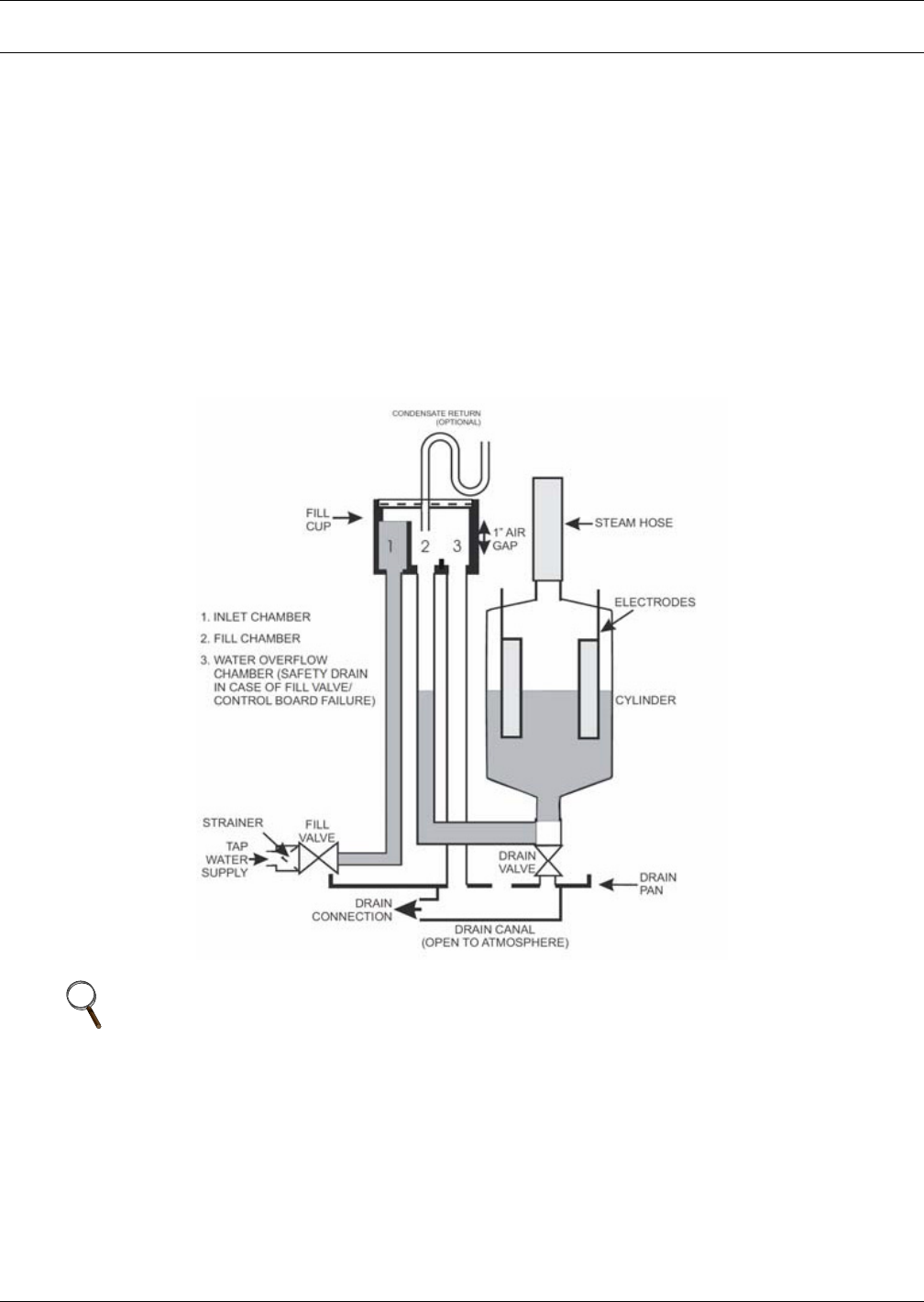
Humidifier
Liebert® CRV™116
APPENDIX A-HUMIDIFIER
A.1 PRINCIPAL OF OPERATION
When the Liebert iCOM® calls, the cylinder fills to 100% of the Full Load Amperage (FLA) or to the
top of the cylinder, whichever comes first. See Figure 100. If it reaches 100% FLA, the water heats
and boils away to a level giving 80% FLA. An electronic timer uses the rate of amp fall to determine
the water level. The objective is to concentrate current carrying minerals in the cylinder so that a
smaller volume of water is required to produce the rated steam output. This extends the life of the
disposable cylinder by minimizing electrode coverage and reducing energy use because the high
concentration allows a minimal drain rate. When 80% FLA is reached, the fill valve will open,
refilling the cylinder to 100% FLA. On occasion, the drain valve will also come on if the water level is
too low, indicating too high a concentration and the need to dilute the water in the cylinder. If the
water reaches the top of the cylinder before 100% FLA, the fill valve shuts Off via the sensor, and the
fill-boil-fill-boil cycle continues, cycling Off the red high water sensor light until the concentration
becomes high enough to reach 100% FLA. The above-described control process will then take over.
Figure 100 General diagram—humidifier operation
NOTE
The Liebert iCOM control monitors the condition of the air discharging from the unit to protect
neighboring electronic equipment. The Liebert iCOM will prevent the humidifier from
activating if the discharge air is near its saturation point. This protects against discharging
fog from the unit or condensation forming on the unit’s supply air baffles. This protection mode
is activated when the supply air leaving the unit is below 64°F (17.8°C) or above 55% relative
humidity. The Liebert iCOM screen will display “Humidifier Suspended.” The screen will
display “Humidifier Resumed” when the protection mode resets at 67°F (19.4°C).
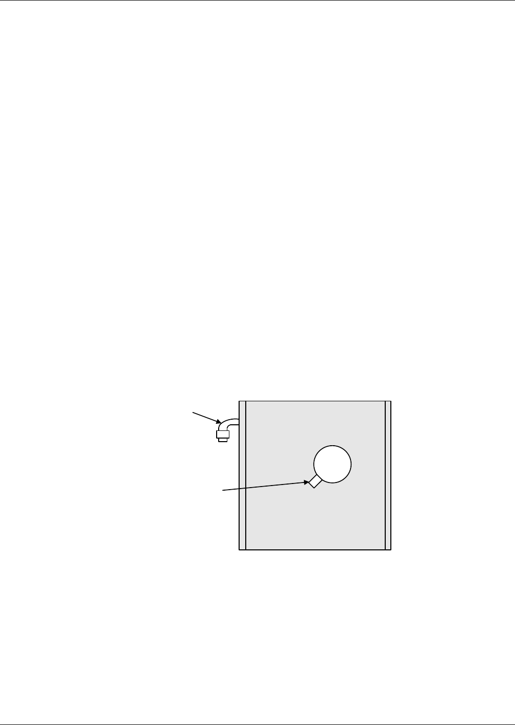
Humidifier
117 Liebert® CRV™
A.1.1 Humidifier Water Supply and Plumbing
The fill valve is sized for an extended water pressure range of 30 to 80 psi.
For installations where water pressure is less than 15 psi, add a pressure boost pump and notify the
factory; a fill valve with an oversized opening will be supplied.
For installations where water pressure is greater than 80 psi, install a pressure reducing valve in the
water feed line to the unit.
With dirty or muddy water sources (e.g., some well sources), ensure proper filtration by adding an
external filter to the water line entering the unit. (Consult factory for accessories such as filters.)
NOTICE
Risk of improper water supply. Can reduce humidifier efficiency or obstruct humidifier
plumbing.
Do not use completely demineralized water with this unit; it is the minerals that allow the
electrode principle to work.
Do not use a hot water source; it will cause deposits that will eventually block the fill valve
opening.
A.1.2 Humidifier Water Connection
A copper compression olive type coupling for 1/4" O.D. soft copper tubing is provided with the unit and
requires no soldering for the water connection to the unit.
An isolating valve should ALWAYS be placed in the feed water line to allow service of the fill valve.
Each unit is fitted with a fill solenoid valve located on the base drain pan.
Flow openings are designed for water pressure from 30 to 80 psi and are protected by the built-in
strainer.
For inlet water pressure outside this range, the factory should be contacted.
Figure 101 Water connection to humidifier
7/8" Drain
Connection
Use 7/8" ID Hose from Factory
3/8" Cold Water
Olive Connection

Humidifier
Liebert® CRV™118
A.1.3 Humidifier Startup and Operation
• Ambient temperature location for humidifier: 41 - 104°F (5 - 40°C).
• Relative humidity location for humidifiers: 5 - 80% RH.
Check to see that the unit is securely mounted on a level surface with the proper drain and water
supply. Check for correct voltage with appropriately sized service. Check that the steam distributor,
steam supply hose and condensate line are correctly installed and routed back to the unit.
Check all electrical connections for wires that may have become loose in shipping. Components
damaged because of loose connections are NOT under warranty.
Check electrode plugs to ensure they are pressed firmly onto the electrode pins. Important: Loose
connections will cause overheating of the cylinder plugs, possibly melting the plugs and/or cylinder.
1. Open the isolating valve in the feed water line to the unit.
2. Make sure the Liebert iCOM® is set high enough to call for humidification.
3. Turn on the main disconnect in the primary service feeding the unit and check that unit has
power at the primary terminal block.
4. Push the auto On/Off/Drain Switch to “On.”
Water will start to enter the cylinder through its bottom port and rise in the cylinder to a point
determined by the solid state control circuitry. It is not unusual upon initial startup for the water to
fill the cylinder and cycle on the red high-water sensor light.
The red light simply acts as a safety to shut off the fill valve and prevent overfilling. With the red
light on, the water in the cylinder will continue to heat and, after a few minutes, start to boil. After
the boiling of the water has lowered the water level below the sensor at the top of the cylinder, the red
light will go out and the fill solenoid will again open until the cylinder is again full. This cycling of the
red light and fill valve will continue until the unit's full output capacity is reached, after which the
water level will automatically lower itself in the cylinder. (The increased concentration allows for
lower electrode coverage while maintaining the same output.) When a stabilized condition is reached,
the water will be boiling close to the cylinder seam level. The solid state circuitry will maintain the
proper concentration in the cylinder by introducing short drains only when necessary. If the cylinder
is manually drained, the above process will repeat itself.
A.1.4 Low Water Conductivity
Should normalization of the unit be required immediately after startup, the installer may speed up
the process by artificially increasing water conductivity. During a fill cycle, the installer should
dissolve half a teaspoon of table salt (no more) in a cup of water and add it to the cylinder by means of
the fill cup attached to the plumbing section. Open the plumbing compartment and add salt solution
through cylinder outlet. Excessive amounts of salt will result in erratic operation of the unit; however,
normalization of the unit will occur automatically through the solid-state control sequence.
A.1.5 Cylinder Replacement
NOTICE
Risk of improper operation. Can cause equipment damage.
The steam cylinder is disposable and must be replaced at the end of cylinder life. Cylinder life
depends on water supply conditions and humidifier usage. Failure to replace the cylinder at
the end of cylinder life may result in unit damage.
After an extended period of operation, the cylinder will be completely used, as indicated by the red
high-water sensor light illuminated on the cabinet. When this condition is reached, a new
replacement cylinder must be installed.
Contact Emerson or your local Emerson representative to obtain a replacement cylinder. To obtain
the correct cylinder, supply the cylinder model from the white three-digit label on the cylinder, or
supply the model, voltage and serial number from the unit specification label.
NOTE
The red light may come on during initial startup, but this does not mean the cylinder must be
replaced. See 9.0 Startup and 12.0 Operation.
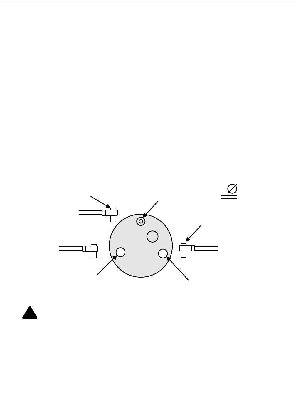
Humidifier
119 Liebert® CRV™
Remove the Old Cylinder
1. Turn Off the water supply to the unit.
2. The old cylinder must be drained completely before removing. This is done by pushing the auto
On/Off/Drain switch to the “drain” position.
3. When the cylinder is empty, push the auto On/Off/Drain switch to the Off position.
4. Open the main disconnect switch during the entire cylinder change operation.
5. The power wires to the cylinder are attached by cylinder plugs to the electrode pins on top of the
cylinder. Pull these plugs off the pins.
6. Using a slotted screwdriver, loosen the steam hose clamp(s) and pull the steam hose off.
The cylinder is now ready to be lifted out of the unit.
Installing the New Cylinder
1. Leave the main disconnect open until the cylinder is completely installed and reconnected.
2. Ensure that the cylinder mounting stubs are seated properly in the allotted side mounting slots
within the unit.
3. The white sensor plug on all units is for the sensor pin, which always goes on the single pin offset
from the others.
4. Ensure that cylinder plugs are snug on the pins.
5. Replace loose-fitting plugs; loose plugs may generate enough heat to melt and destroy the plug,
and new cylinder plugs must be ordered.
Reverse the procedure to install a new cylinder.
Figure 102 Sensor pins, cylinder plugs
Humidifier Maintenance
Extended Shutdown
Always drain the cylinder before disconnecting power to the humidifier for a period of extended
shutdown. Otherwise, the electrodes are subject to harmful corrosion, which drastically shortens the
cylinder life. Do not leave the switch in the DRAIN position indefinitely because the drain coil could
burn out. Leave the switch in the Off position and open the main external fused disconnect to stop
power to the humidifier. Close the shutoff valve in the water supply line feeding the humidifier.
!
WARNING
Risk of electric shock. Can cause injury or death.
Disconnect all local and remote electric power supplies before working within. The plumbing
and electrical compartments contain high-voltage components and wiring. The access cover is
attached with screws. Access should be limited to authorized personnel only.
Cylinder Pin Cylinder Pin
Sensor Pin
Cylinder
Plug
White
Sensor
Plug
1
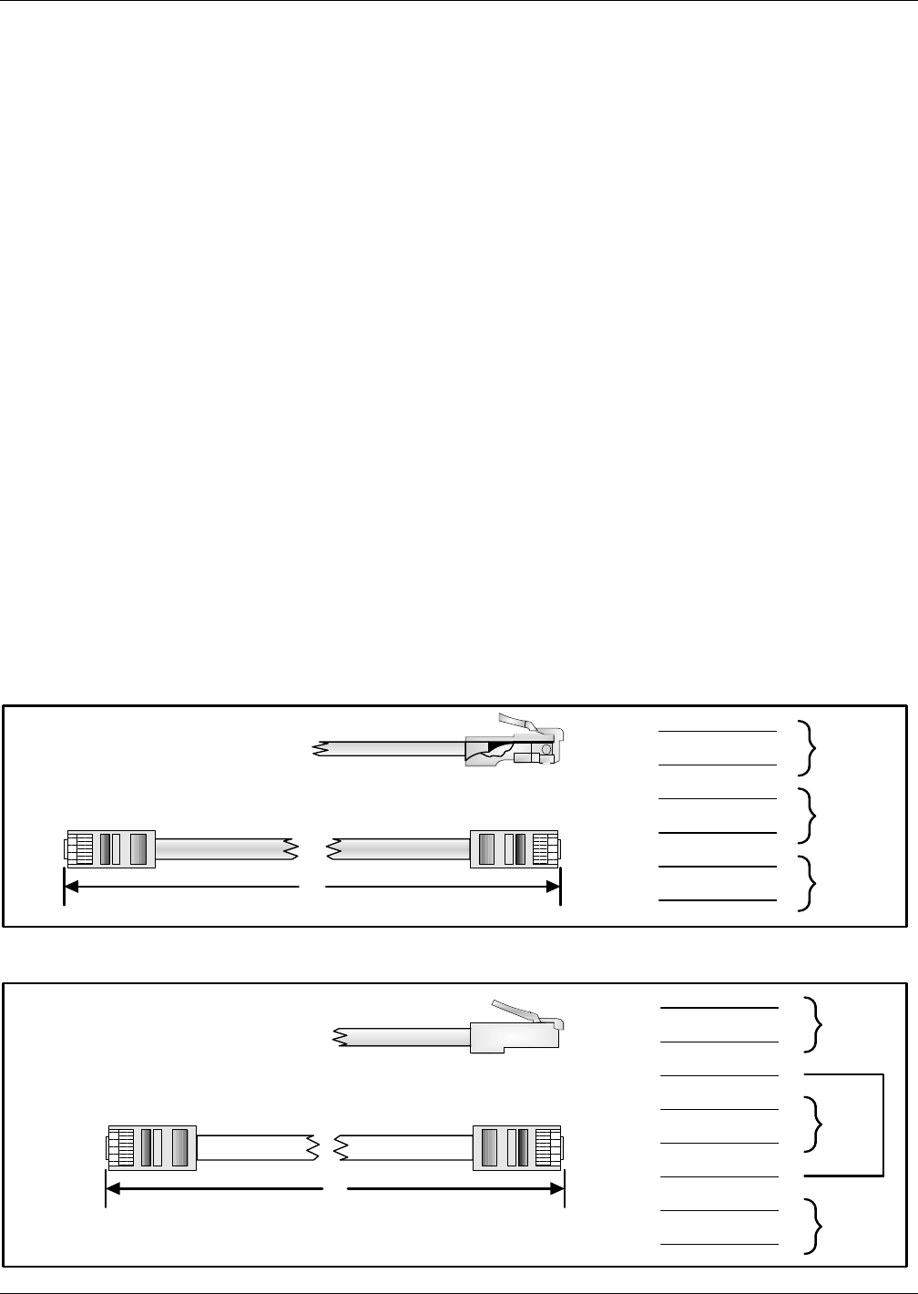
Humidifier
Liebert® CRV™120
A.1.6 Humidifier Troubleshooting
Terms Used
•FLA (Full Load Amps) are amps listed on the humidifier specification label.
•Short cycling occurs when the humidifier’s “On time” is less than 10 minutes upon a call for
humidity. To correct short cycling, all humidifiers have a capacity adjustment that allows the out-
put of the humidifier to be reduced to as low as 20% of rated output, thus extending the “on time”
required to maintain output.
•Foaming can occur when the impurities already in water reach an excess concentration as a
result of boiling away water and continued boiling agitates the contained water. The humidifier
electronics are designed to prevent foaming, although in extreme cases water will foam with little
concentration, making it necessary to increase the drain time of the water contained in the cylin-
der. Foaming is normally caused by short cycling, a restricted drain or back pressure. The foam
generated in these instances is conductive and may lead to false full-cylinder indication if the
level of the foam approaches the top of the cylinder.
•Back pressure is the restriction of steam flow caused by long steam runs, improperly sloped
steam lines, elbows changing the direction of steam flow from horizontal to vertical without a
drain leg, any plumbing detail allowing the accumulation of condensate, undersized steam line,
improper steam distributor, downward air flow onto the distributor causing excess static pressure
at the steam outlets, or high static pressure ducts (not probable). To overcome excess static pres-
sure in the duct, use a fill cup extension kit. In downflow applications, a downflow distributor
should be used, but in some cases the fill cup extension will also be required.
•Reset unit (humidifier): To reset the humidifier, switch the auto On/Off/Drain switch at the front
of the humidifier to the Off position for at least five seconds, then switch it back to the On position.
•Monitored leg is the primary wire to the cylinder that loops through the current sensing device
of the main PCB. This wire ends at the red cylinder plug at the cylinder.
A.2 REMOTE RACK SENSOR TROUBLESHOOTING
If the sensor has been set up correctly and is communicating to the Liebert CRV, then the status of
the LED (DS1) located on the sensor circuit board will be solid green.
Figure 103 CAN bus and Ethernet cable wiring
Ethernet cable; suitable for U2U connection or for connecton of the Liebert iCOM Large Coldfire Display;
all through switch or hub
Six-wire CAN bus cable; suitable for Liebert iCOM board with THB, HCB and Liebert iCOM display connections
1
2
3
4
5
6
7
8
1
2
3
4
5
6
7
8
Pair 4
Pair 2
Pair 3
Pair 1
A
1
2
3
4
5
6
Pair 2
Pair 3
Pair 1
A
1
2
3
4
5
6

Humidifier
121 Liebert® CRV™
A.3 STARTING POINT
Auto On/Off/Drain switch in On position—unit will not fill:
When the On/Off control circuit is made and the Auto On/Off/Drain switch is pushed to On, the 24V
holding coil of the primary contactor should energize. The resulting magnetic pull closes the high
voltage contacts with a distinct and audible “clunk.” If the contactor will not make the connection,
then inspect the following while referring to the wiring diagram:
• Check for 24V across terminals 18 and 26 on the PC board.
• The low-voltage 3A fuse located in the control box may be blown.
• The contactor holding coil may be open or shorted.
• The switch may be defective.
Recheck that the Auto On/Off/Drain switch is still On. If it is, shut off the main disconnect and check
fuses or breaker of the main disconnect. If they are serviceable, turn power back on.
To test for a defective Auto On/Off/Drain switch, connect a wire from the fuse directly to Terminal 6
on the external controls strip. If the contactor activates, the On side of the switch is defective. If the
contactor does not activate, the PC board could be defective.
If the 3A control fuse blows when the wire from the fuse touches Terminal 6 on the external controls
strip, the contactor holding coil may be shorted. Replace contactor if necessary.
After the necessary components have been replaced and the contactor pulls in, there is line voltage to
the cylinder and the control sequence can begin.
Approximately 30 seconds after the contactor pulls in, the fill valve coil should energize. There is also
a visible fill relay on the printed circuit board. It is the one located farthest from the C.T. core. The
points on this relay must be touching in order for the fill valve coil to be energized. If the points do not
touch after the built-in time delay, the sensor input may be interfering. To confirm, remove the black
and red sensor wires from terminals 6 and 10 on the PC board. Wait 30 seconds and, if the fill relay
points do not touch, replace the sensor. If they still do not touch, the basic PC board may be faulty. To
confirm, disconnect the red wire from terminal 18 and touch it to terminal 14. If the fill valve coil
activates, the basic PC board should be replaced. If it still does not activate, the fill valve coil should
be replaced. After the necessary components have been changed, water will start filling the cylinder
and begin to submerge the electrodes. Because of the high voltage across the electrodes, the water can
now conduct electricity.
Red “Change Cylinder” light on—Water at top of cylinder:
This is a common occurrence on startup. See 9.0 Startup and 12.0 Operation.
Water remains at high level and won't concentrate:
This is normal on cold startup and can be accelerated by adding a maximum of 1/2 tsp. of dissolved
salt to the cylinder on fill cycle through the plastic fill cup. See A.1.4 Low Water Conductivity.
If the unit has been operating extensively, observe for normal fill-boil-fill-boil cycle; no drainage
should occur. If drainage occurs, check for leaking drain valve or back pressure.
Unit drains continually:
May be caused by foaming and/or back pressure or by a leaking drain valve.
If cylinder is almost empty, check for magnetic pull on drain solenoid indicating miswiring. If there is
no pull, drain actuator is blocked open; remove, disassemble and clean.
If drain is occurring through activated drain valve, valve is miswired or electronics are faulty; consult
factory.
If drain is occurring through the overflow on the fill cup, this is due to abnormal restriction on the
steam line and back pressure forcing water out of the cylinder so water cannot concentrate and level
remains high. Review installation of steam line to ensure there are no blockages or excessive static
pressure in the air system.

Humidifier
Liebert® CRV™122
Table 31 Humidifier troubleshooting
Unit Status Lamp
Symptom Corrective actions Yellow Green
On On Maximum water level inside
cylinder.
This usually happens on initial start-up after replacing the
cylinder (normal). Water is concentrated with minerals
inside the cylinder. Let unit run; yellow light will disappear
when the unit is at full output. This may take a day or two.
Off Off No power to the board.
Check for main power supply fault. Turn power switch to
'Drain' position. If drain valve is activated (sound of
solenoid), check connection to the board or board itself.
When no sound is present, check fuse (replace with 3.0 A if
needed), transformer (voltage should be present between
fuse holder and ground screw).
1 flash
sequence Off
Excess current. Operating
amperage exceeded 130% of rated
amps. Water is drained from the
cylinder (drain valve on for 10
minutes).
Check drain valve operation, drain time, possible drain
restrictions. Check fill valve for leaks (not holding supply
water). Back pressure may also cause very conductive
water conditions. Was the humidifier short cycling? Check
for short cycling. Water conductivity too high.
2 flashes in
sequence Off No current detection for 30 minutes
with continuous call for humidity.
Check water level in the cylinder - should be more than 1/4
full. If not, check fill rate, 24 VAC voltage on fill valve
terminals (unit must be on with call for humidity - green light
on steadily). Verify fresh water supply to the humidifier.
Leaking drain valve may be at fault (minerals blocking the
plunger). If cylinder is more than 1/4 full, check primary
power, connections to the cylinder, continuity of wires to
cylinder. Are power wires connected to proper terminals on
the cylinder? (Color coding.) Possibly wrong cylinder type.
Low water conductivity.
4 flashes in
sequence Off End of cylinder life - change
cylinder.
Check water level in the cylinder; should be about 3/4 full.
Check for foaming if water level is lower or cylinder life
shorter than expected. Change cylinder, clean drain valve.
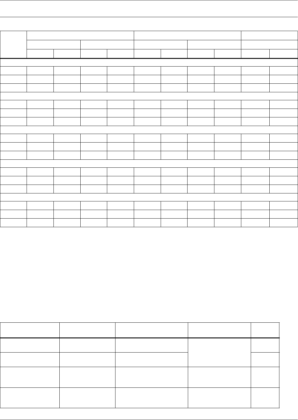
Electrical Data
123 Liebert® CRV™
APPENDIX B-ELECTRICAL DATA
NOTICE
Risk of exceeding line-to-ground limit. Can cause equipment damage.
The electrically commutated (EC) motors included in 480V CR035 and CR040 units are
suitable for connection to power supplies with 300V or less line to ground potential. Excess
line-to-ground voltage can cause capacitor failure internal to the motors.
• Power supplies such as 480V WYE with solidly grounded neutral have 277V line to ground
and are acceptable.
• Power supplies such as 480V WYE with high resistance (or impedance) ground, 480V delta
without ground or with floating ground, 480V delta with corner ground or 480V delta with
grounded center tap will exceed the 300V line-to-ground limit.
Table 32 Liebert CRV electrical data - 60Hz (Amps)
Voltage
Air-Cooled Units Water/Gylcol-Cooled Units Chilled Water Units
CR035RA CR020RA CR035RW CR020RW CR040RC
460/3/60 208/3/60 460/3/60 208/3/60 460/3/60 208/3/60 460/3/60 208/3/60 460/3/60 208/3/60
Cooling with Dehumidifying, Condensate Pump, Reheat; with or without Humidifier
FLA 31.7 62.0 24.3 51.0 31.7 62.0 24.3 51.0 11.7 24.9
WSA 38.6 75.4 29.3 61.6 38.6 75.4 29.3 61.6 14.6 31.1
OPD 50 100 35 80 50 100 35 80 20 35
Cooling with Dehumidifying, Condensate Pump and Humidifier; NO Reheat
FLA 27.9 53.8 20.5 42.8 27.9 53.8 20.5 42.8 7.9 16.7
WSA 32.9 63.1 23.6 49.3 32.9 63.1 23.6 49.3 9.9 20.9
OPD5090357050903570 15 25
Cooling with Dehumidifying and Condensate Pump, NO Reheat, NO Humidifier
FLA 24.2 45.4 16.8 34.4 24.2 45.4 16.8 34.4 4.2 8.3
WSA 29.2 54.7 19.9 40.9 29.2 54.7 19.9 40.9 4.6 9.1
OPD4590306045903060 15 15
Cooling with Dehumidifying and Reheat; NO Condensate Pump, NO Humidifier
FLA 30.5 59.7 23.1 48.7 30.5 59.7 23.1 48.7 10.5 22.6
WSA 37.4 73.1 28.1 59.3 37.4 73.1 28.1 59.3 13.1 28.3
OPD 50 100 35 80 50 100 35 80 15 30
Cooling with Dehumidifying, NO Condensate Pump, NO Reheat, NO Humidifier
FLA 23.0 43.1 15.6 32.1 23.0 43.1 15.6 32.1 3.0 6.0
WSA 28.0 52.4 18.7 38.6 28.0 52.4 18.7 38.6 3.4 6.8
OPD4580306045803060 15 15
Table 33 Calibration of electrical components
Refrigeration Circuit
Item No. Component Setting Notes Contact
18-19 High Pressure
Transducer
Range 045 barg
Output 05V See Liebert iCOM®
User Manual, SL-18835
—
14 Low Pressure
Transducer
Range 017.3 barg
Output 05V —
3High Pressure
Switch (HP)
STOP 38.7±1 barg
START 30.0±1.5 barg
(fixed setting manual reset)
Reset Normally
Closed
—
Clogged Filter
Differential Pressure
Switch (CF)
Setpoint range 0.54 mbar
Filter G4 = 2 mbar Setting Ring Normally
Closed

Electrical Field Connections Descriptions
Liebert® CRV™124
APPENDIX C-ELECTRICAL FIELD CONNECTIONS DESCRIPTIONS
C.1 STANDARD ELECTRICAL CONNECTIONS
(Source: DPN001884, Rev. 4, Page 1)
1. High Voltage Connection Through the Bottom of the Electric Panel—1-3/8" (34.9mm),
1-3/4" (44.5mm) 2-1/2" (64mm) diameter concentric knockout.
2. Low Voltage Connection Through the Bottom of the Electric Panel—Quantity (2) 7/8"
(22mm) diameter knockouts.
3. High Voltage Connection Through the Top of the Unit—1-3/8" (34.9mm), 1-3/4" (44.5mm)
and 2-1/2" (64mm) diameter concentric knockout.
4. Low Voltage Connection Through the Top of the Unit—Quantity (4) 7/8" (22mm) diameter
knockouts.
5. Three-Phase Electrical Service—Connect to terminals on disconnect switch. Three-phase
service not by Liebert (see NOTICE on page 125).
6. Factory-Installed locking Disconnect Switch
7. Earth Ground—Terminal for field-supplied earth grounding wire.
8. Remote Unit Shutdown—Replace existing jumper between Terminals 37 and 38 with
field-supplied normally closed switch having a minimum 75VA, 24VAC rating. Use field-supplied
Class 1 wiring.
9. Customer Alarm Inputs—Terminals for field supplied, normally closed contacts, having a
minimum 75VA, 24VAC rating, between Terminals 3 and 50, 2 and 51, 5 and 55 or between 3 and
56. Use Class 1, field-supplied wiring. Terminals 3 and 56 are used for humidifier alarm when a
humidifier is installed. The remaining terminals are available for customer alarm inputs, such as
smoke sensors and building fire alarms.
10. Common Alarm—On any alarm, normally open dry contact is closed across Terminals 75 and 76
for remote indication. 1A, 24VAC maximum load. Use field-supplied Class 1 wiring.
11. Heat Rejection Interlock—On any call for compressor operation, normally open dry contact is
closed across Terminals 70 and 71 to heat rejection equipment. 1A, 24VAC maximum load. Use
field-supplied Class 1 wiring.
C.2 ELECTRICAL CONNECTIONS FOR OPTIONAL FEATURES
12. Condensate Pump High Water Alarm (available when optional pump is installed)—On
pump high water indication, normally open dry contact is closed across Terminals 88 and 89 for
remote indication. 1A, 24VAC maximum load. Use field-supplied Class 1 wiring.
13. Liebert Liqui-tect® Shutdown and Dry Contact (Available When Optional Liebert
Liqui-tect Sensor is Installed)—On Liebert Liqui-tect activation, normally open dry contact is
closed across Terminals 58 and 59 for remote indication. The Liebert Liqui-tect sensor notifies
Liebert iCOM of indication through Terminals 60 and 61. 1A, 24VAC maximum load. Use
field-supplied Class 1 wiring.
14. Reheat and humidifier lockout—Remote 24VAC required at Terminals 82 and 83 for lockout
of reheat and humidifier.
15. Additional Common Alarm—On any alarm, one additional normally open dry contact is closed
across Terminals 94 and 95 for remote indication. 1A, 24VAC maximum load. Use field-supplied
Class 1 wiring.
NOTE
Refer to specification sheet for total unit full load amps, wire size amps and maximum
overcurrent protective device size.
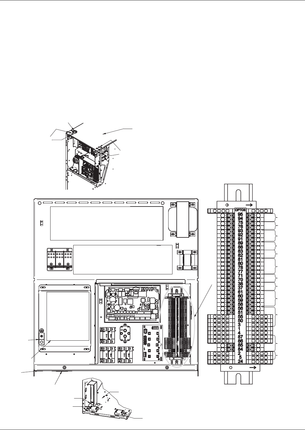
Electrical Field Connections Descriptions
125 Liebert® CRV™
NOTICE
Risk of improper input power. Can cause equipment damage.
The electronically commutated motors included in the Liebert CRV unit are suitable for
connection to an electrical service providing input power to the unit with 300V or less line-to-
ground potential only.
Acceptable unit input electrical service for 460V (480V) nominal units:
• 480V wye with solidly grounded neutral and 277V line-to-ground
Unacceptable unit input electrical service for 460V (480V) nominal units
• Wye with high resistance (or impedance) ground
• Delta without ground or with floating ground
• Delta with corner ground
• Delta with grounded center tap
Figure 104 Electrical field connections
DPN001884
Page 3, Rev. 4
3
4
7
1
Unit
Base
2
5, 6
Typically, 2
9
9
13
11
14
12
10
8
Not
Used
Not
Used
12
15
4
Unit Top
OVERLOAD PROTECTORS
CONTACTORS
UNIT
DISCONNECT
SWITCH
2-1/2" (64mm) K.O.
1-3/32" (28mm) K.O.
1-3/4" (44.5mm) K.O.
Refer to C.1 Standard Electrical Connections and
C.2 Electrical Connections for Optional Features for
keys to numbered components.
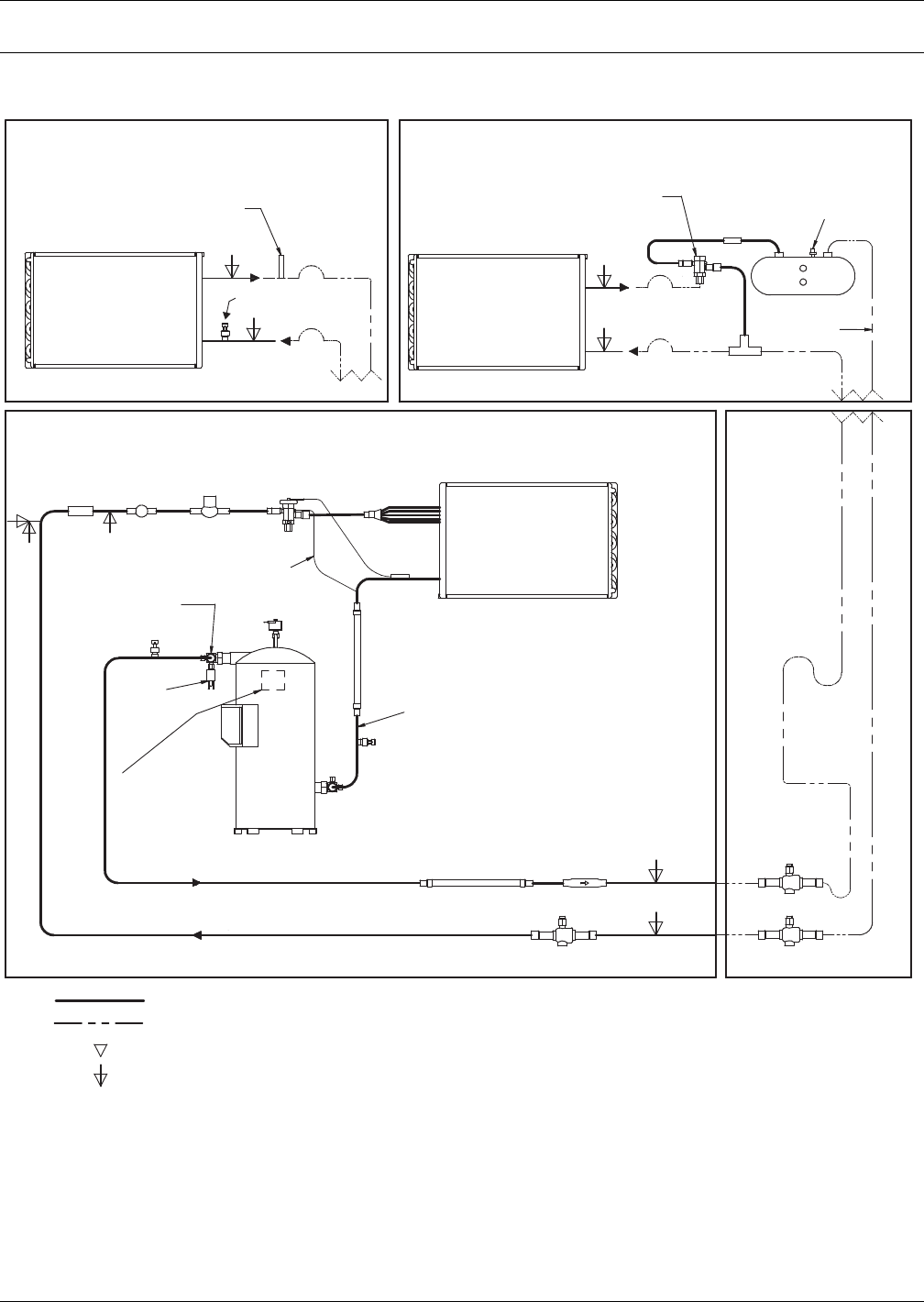
Refrigeration and Hydraulic Circuits
Liebert® CRV™126
APPENDIX D-REFRIGERATION AND HYDRAULIC CIRCUITS
Figure 105 General arrangement—air-cooled units
Distributor
+
+
Suction Line
DPN001984
Rev. 4
Factory Refrigerant Piping
Field Piping
Outdoor VFD Condenser
Vibration
Absorber
Vibration Absorber Check Valve
Low-Pressure Transducer
High-Pressure
Transducer
* Components are not supplied by
Liebert but are recommended for
proper circuit operation and
maintenance. Should be located
near the indoor Liebert CRV unit.
+ Inverted Trap on Discharge and
Liquid Lines to extend above the
base of the coil by a minimum of
7-1/2" (190mm).
Digital
Scroll
Compressor
1. Schematic representation shown. Do not use for specific connection locations.
2. One or more additional pressure relief valves are required downstream of any
and all field-installed isolation. Do not isolate any refrigerant circuits from
overpressurization protection.
CR020 Digital
Solenoid Valve
Expansion
Valve
External Equalizer
CR035 Digital
Solenoid Valve
Hot Gas Discharge
Hot Gas Discharge
VFD Transducer
Sensing
Bulb
Optional Field-Installed
Fusible Plug
Service Valve
High-
Pressure
Cut Out
Condenser Coil
(VFD)
Solenoid
Valve
Sight
Glass
Filter
Drier
Service Valve
*Isolation Valve
*Isolation Valve
* Traps Every
15ft. (4.6m)
of Rise
Evaporator Coil
Liquid Return
Service / Schrader (Access) Connection With Valve Core
+
+
Outdoor Lee-Temp Condenser
Check Valve
Condenser Coil
(Liebert Lee-Temp)
Hot Gas Discharge
Relief Valve
Liquid
Return
Lee-Temp Receiver
Head Pressure
Control Valve
Service / Schrader (Access) Connection No Valve Core
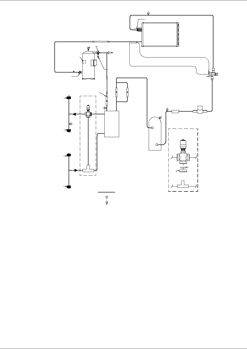
Refrigeration and Hydraulic Circuits
127 Liebert® CRV™
Figure 106 General arrangement—water-glycol units
Check Valve
AB
B
A
A
AB
B
NOTES
1. Schematic representation shown. Do not use for specific connection locations.
2. Install a 35 mesh straine r, in an easily accessible location, on the water/glycol
supply to prevent particles from entering the heat exchange r. Strainer bypass
valves are reccomended to allow the strainer to be cleaned while maintaining
flow to the cooling unit.
DPN001985
Rev. 1
Service / Schrader (Access) Connection With Valve Core
Evaporator Coil
Digital
Scroll
Compressor
Rotalock Valve
Rotalock Valve
High-Pressure Switch
Vibration
Absorber
Vibration
Absorber
High-
Pressure
Transducer
CR020 Digital
Solenoid Valve
Water/Glycol Return
Top Connection
Water/Glycol Return
Bottom Connection
Water/Glycol Supply
Bottom Connection
Water/Glycol Supply
Top Connection
Filter
Drier
Solenoid
Valve
Expansion
Valve
External Equalizer
Receiver
2-Way Valve
Configuration
Blocker
Disk
Valve
Fitting
Check
Va l ve
Differential
Check Valve
(145psi)
Water
Cooled
Brazed
Plate
Condenser
3-Way Valve
Configuration
Sensing
Bulb
Relief
Valve
CR035 Digital
Solenoid Valve
Low Pressure
Transducer
Distributor
Factory Refrigerant Piping
Service / Schrader (Access) Connection No Valve Core
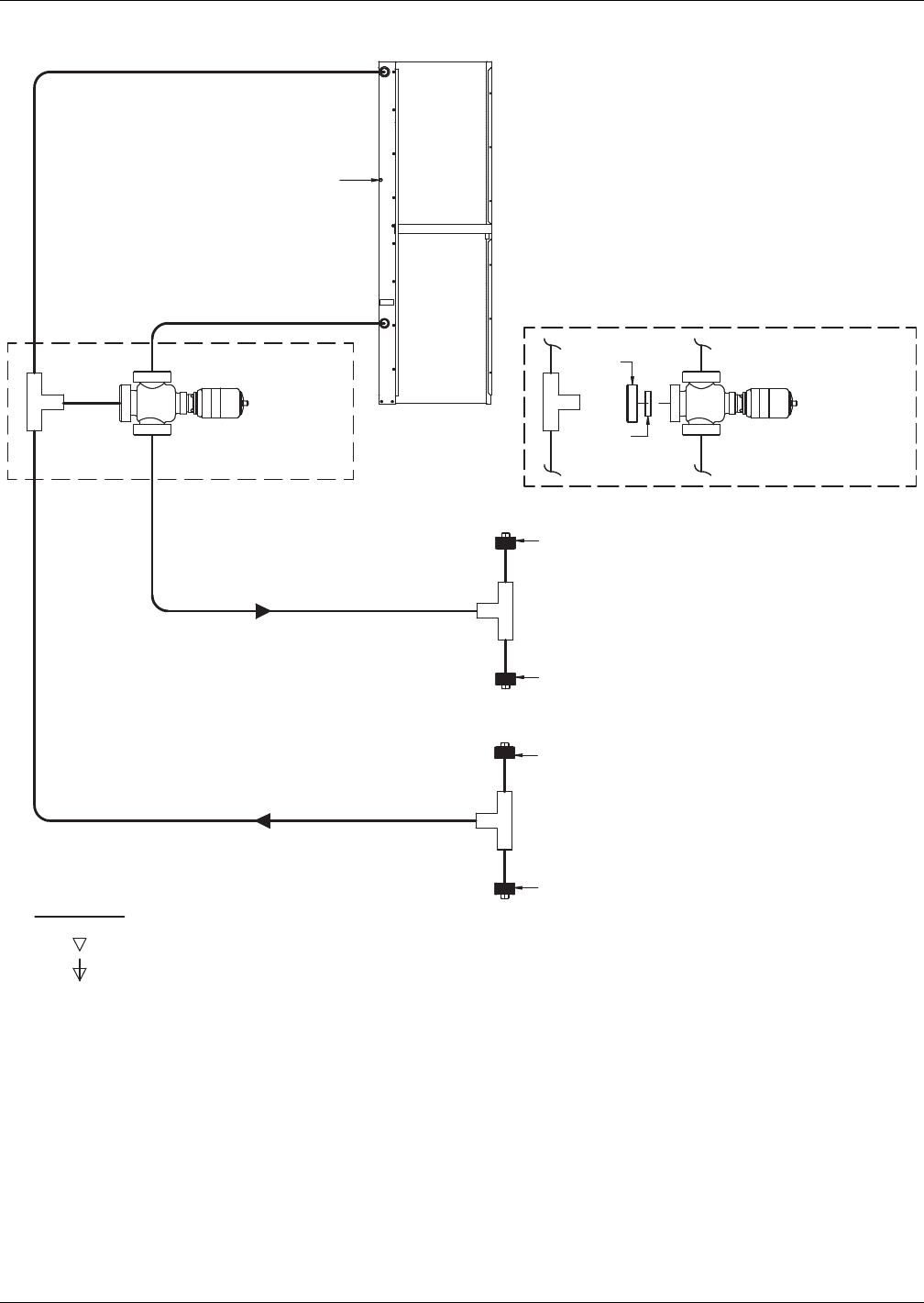
Refrigeration and Hydraulic Circuits
Liebert® CRV™128
Figure 107 General arrangement—chilled water
B
AB
A
A
AB
B
DPN001986
Rev. 1
NOTE: Schematic representation shown.
Do not use for specific connection locations.
Factory Refrigerant Piping
3-Way Chilled Water
Valve Configuration
Air Bleed Valve
2-Way Chilled Water
Valve Configuration
Plug Pipe
Chilled Water Return
(Top of Unit Connection)
Plug Pipe
Chilled Water Return
(Bottom of Unit Connection)
Plug Pipe
Chilled Water Supply
(Top of Unit Connection)
Chilled
Water
Coil
Blocker
Disk
Valve
Fitting
Service / Schrader (Access) Connection No Valve Core
Service / Schrader (Access) Connection With Valve Core

Refrigeration and Hydraulic Circuits
129 Liebert® CRV™
NOTES

Refrigeration and Hydraulic Circuits
Liebert® CRV™130

Ensuring The High Availability
Of Mission-Critical Data And Applications.
Emerson Network Power, a business of Emerson (NYSE:EMR),
is the global leader in enabling Business-Critical Continuity
™
from grid to chip for telecommunication networks, data centers,
health care and industrial facilities. Emerson Network Power
provides innovative solutions and expertise in areas including
AC and DC power and precision cooling systems, embedded
computing and power, integrated racks and enclosures,
power switching and controls, infrastructure management,
and connectivity. All solutions are supported globally by local
Emerson Network Power service technicians. Liebert AC power,
precision cooling and monitoring products and services
from Emerson Network Power deliver Efficiency Without
Compromise
™
by helping customers optimize their data center
infrastructure to reduce costs and deliver high availability.
While every precaution has been taken to ensure the accuracy
and completeness of this literature, Liebert Corporation assumes no
responsibility and disclaims all liability for damages resulting from use of
this information or for any errors or omissions.
© 2009 Liebert Corporation
All rights reserved throughout the world. Specifications subject to change
without notice.
® Liebert is a registered trademark of Liebert Corporation.
All names referred to are trademarks
or registered trademarks of their respective owners.
Technical Support / Service
Web Site
www.liebert.com
Monitoring
liebert.monitoring@emerson.com
800-222-5877
Outside North America: +00800 1155 4499
Single-Phase UPS & Server Cabinets
liebert.upstech@emerson.com
800-222-5877
Outside North America: +00800 1155 4499
Three-Phase UPS & Power Systems
800-543-2378
Outside North America: 614-841-6598
Environmental Systems
800-543-2778
Outside the United States: 614-888-0246
Locations
United States
1050 Dearborn Drive
P.O. Box 29186
Columbus, OH 43229
Europe
Via Leonardo Da Vinci 8
Zona Industriale Tognana
35028 Piove Di Sacco (PD) Italy
+39 049 9719 111
Fax: +39 049 5841 257
Asia
29/F, The Orient Square Building
F. Ortigas Jr. Road, Ortigas Center
Pasig City 1605
Philippines
+63 2 687 6615
Fax: +63 2 730 9572
Emerson Network Power.
The global leader in enabling Business-Critical Continuity™
EmersonNetworkPower.com
Emerson, Business-Critical Continuity, Emerson Network Power and the Emerson Network Power logo are trademarks of Emerson Electric Co. or one of its affiliated companies.
©2009 Emerson Electric Co.
AC Power
Connectivity
DC Power
Embedded Computing
Embedded Power
Infrastructure Management & Monitoring
Outside Plant
Power Switching & Controls
Precision Cooling
Racks & Integrated Cabinets
Services
Surge Protection
SL-11975_REV8_11-12
