Emerson Liebert Xdr Users Manual
2015-01-05
: Emerson Emerson-Liebert-Xdr-Users-Manual-164291 emerson-liebert-xdr-users-manual-164291 emerson pdf
Open the PDF directly: View PDF ![]() .
.
Page Count: 40
- Important Safety Guidelines
- Save These Instructions
- 1.0 Component Locations and Model Number Nomenclature
- 2.0 Introduction
- 3.0 General Product Information
- 4.0 Mechanical Considerations
- 5.0 Installation
- 6.0 Piping
- 6.1 European Union Fluorinated Greenhouse Gas Requirements
- 6.2 System Connection Configuration
- 6.3 Connection Methods and Points
- 6.4 Insulation
- 6.5 Venting the Holding Charge for Hard-Piped or Removable Liebert XD Flex Pipe Couplings
- 6.6 Hard-Piped Connection Sizes
- 6.7 Field Installation of Liebert XD Flex Pipe Kit on Liebert XDR
- Figure 16 Liebert XD Flex Pipe dimensions—straight and 90-degree connections
- 6.7.1 Connecting Methods—One-Shot Couplings for Pre-Charged Refrigerant Option
- 6.7.2 Connect a Liebert XDR with One-Shot Couplings to Liebert XD Flex Pipe
- 6.7.3 Connection Methods—Removable Couplings
- 6.7.4 Connect Liebert XD Flex Pipe with Removable Coupling to a Liebert XD Cooling Module
- 6.7.5 Connect a Liebert XDR with Liebert XD Flex Pipe to a Liebert XD System
- Tools Required
- Figure 23 Coupling size indicator
- Figure 24 Liebert XD prefabricated piping assembly
- Figure 25 Oil rings on header and Liebert XD Flex Pipe connectors
- Table 5 Torque for connecting Liebert XD Flex Pipe to prefabricated piping
- Figure 26 Wrench arrangement for tightening couplings
- Figure 27 Detail view of Liebert XD Flex Pipe and prefabricated piping port
- Figure 28 Liebert XD prefabricated piping assembly and Liebert XD Flex Pipe
- Tools Required
- 6.7.6 Disconnect a Liebert XD Flex Pipe from a Liebert XD System
- 6.7.7 Disconnecting the Liebert XD Flex Pipe from the Liebert XDR
- 6.7.8 Removing the Liebert XDR from a Cabinet
- 7.0 Installation Checklist and System Fill for Startup
- 8.0 Starting the Liebert XD System
- 9.0 Maintenance
- 10.0 Specifications
Precision Cooling
For Business-Critical Continuity™
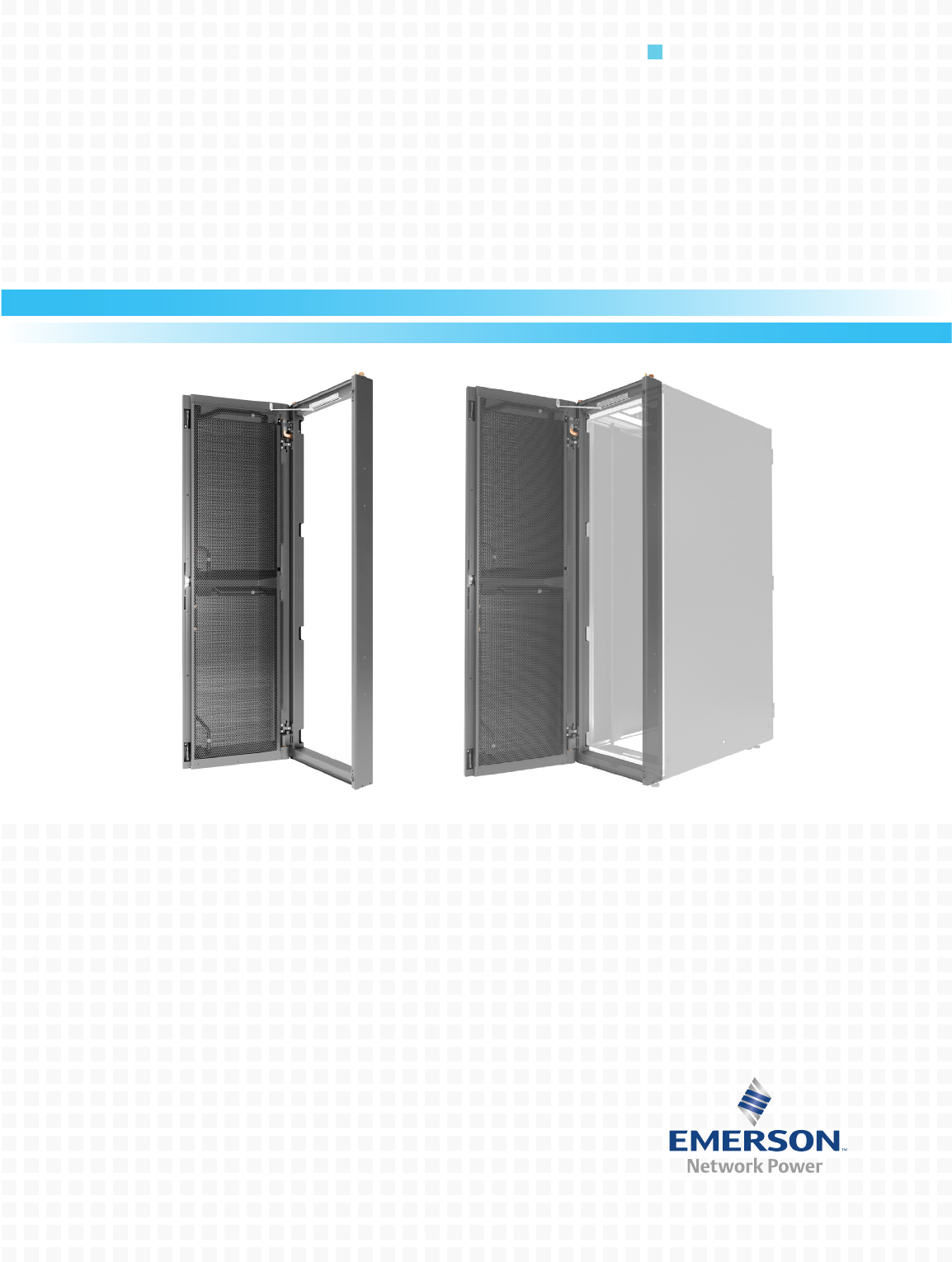
Liebert® XDR™
User Manual
IMPORTANT SAFETY GUIDELINES
SAVE THESE INSTRUCTIONS
NOTICE
Risk of overhead interference. Can cause module or structural damage.
The module may be too tall to fit through a doorway while on the skid. Measure the module
and doorway heights and verify clearances by referring to the installation plans and other
site-specific drawings and documents before moving the module.
Fluorinated Greenhouse Gas Requirements—European Union
Stationary air conditioning, refrigeration, heat pump equipments and stationary fire protection systems in
the European Community market and operating with fluorinated greenhouse gases (f-gas), such as R407C,
R134a, R410A, must comply with the F-Gas Regulation: (EC) No. 842/2006 (F-gas). The regulation prohibits,
among other actions, venting fluorinated greenhouse gases to the atmosphere.
The F-Gas Regulation also requires operators to use all measures that are technically feasible and do not
entail disproportionate cost to prevent leakage of these gases, to test for leakage regularly and to recover f-gas
during equipment service and maintenance and before disposing of equipment.
Refer to the full regulation for additional details.
!
WARNING
Risk of top-heavy module falling over. Can cause equipment damage, personal injury or
death.
Improper handling can cause equipment damage, injury, or death. Read all of the following
instructions before attempting to move, lift, remove packaging from the module, or preparing
module for installation.
!
WARNING
Risk of explosive discharge of high-pressure refrigerant. Can cause personal injury or death.
This module contains fluids and/or gases under high pressure. Relieve system pressure before
cutting into or disconnecting piping or piping components.
!
WARNING
Risk of piping and component rupture. May cause equipment damage, personal injury or
death.
Closing service valves may isolate liquid refrigerant, causing high pressure and rupture of
piping. Do not close valves without following recommended procedures for repair,
maintenance and replacement of components. Install pressure relief valves in field piping
that may become isolated by service valves.
!
CAUTION
Risk of sharp edges, splinters and exposed fasteners. Can cause personal injury.
Only properly trained personnel wearing appropriate safety headgear, gloves, shoes and
glasses should attempt to move, lift, remove packaging from, or prepare module for
installation.
!
CAUTION
Risk of improper operation and overpressurization. Can cause in personal injury or property
damage.
Only personnel properly trained and qualified in HVAC installation or service should install
or service this equipment.
Read all installation, operating and safety instructions before proceeding.

i
TABLE OF CONTENTS
IMPORTANT SAFETY GUIDELINES . . . . . . . . . . . . . . . . . . . . . . . . . . . . . . . . . . INSIDE FRONT COVER
1.0 COMPONENT LOCATIONS AND MODEL NUMBER NOMENCLATURE. . . . . . . . . . . . . . . . . . . . .1
2.0 INTRODUCTION . . . . . . . . . . . . . . . . . . . . . . . . . . . . . . . . . . . . . . . . . . . . . . . . . . . . . . . . . .2
2.1 References . . . . . . . . . . . . . . . . . . . . . . . . . . . . . . . . . . . . . . . . . . . . . . . . . . . . . . . . . . . . . . . . . . 2
2.2 Pre-Installation Checks . . . . . . . . . . . . . . . . . . . . . . . . . . . . . . . . . . . . . . . . . . . . . . . . . . . . . . . 2
2.3 Packing List . . . . . . . . . . . . . . . . . . . . . . . . . . . . . . . . . . . . . . . . . . . . . . . . . . . . . . . . . . . . . . . . 2
2.4 Installation Considerations . . . . . . . . . . . . . . . . . . . . . . . . . . . . . . . . . . . . . . . . . . . . . . . . . . . . 2
2.4.1 Room Preparation. . . . . . . . . . . . . . . . . . . . . . . . . . . . . . . . . . . . . . . . . . . . . . . . . . . . . . . . . . . . . 2
3.0 GENERAL PRODUCT INFORMATION . . . . . . . . . . . . . . . . . . . . . . . . . . . . . . . . . . . . . . . . . . .3
3.1 Product/System Description. . . . . . . . . . . . . . . . . . . . . . . . . . . . . . . . . . . . . . . . . . . . . . . . . . . . 3
3.2 Checking and Unpacking . . . . . . . . . . . . . . . . . . . . . . . . . . . . . . . . . . . . . . . . . . . . . . . . . . . . . . 3
3.2.1 Recyclable Packaging . . . . . . . . . . . . . . . . . . . . . . . . . . . . . . . . . . . . . . . . . . . . . . . . . . . . . . . . . . 4
3.2.2 Module Handling . . . . . . . . . . . . . . . . . . . . . . . . . . . . . . . . . . . . . . . . . . . . . . . . . . . . . . . . . . . . . 4
3.2.3 Unpacking the Module . . . . . . . . . . . . . . . . . . . . . . . . . . . . . . . . . . . . . . . . . . . . . . . . . . . . . . . . . 5
3.2.4 Removing the Liebert XDR from the Pallet . . . . . . . . . . . . . . . . . . . . . . . . . . . . . . . . . . . . . . . . 7
4.0 MECHANICAL CONSIDERATIONS . . . . . . . . . . . . . . . . . . . . . . . . . . . . . . . . . . . . . . . . . . . . .8
4.1 Liebert XDR Dimensions . . . . . . . . . . . . . . . . . . . . . . . . . . . . . . . . . . . . . . . . . . . . . . . . . . . . . . 8
4.2 Determining Placement in the Conditioned Space. . . . . . . . . . . . . . . . . . . . . . . . . . . . . . . . . 10
4.3 Airflow. . . . . . . . . . . . . . . . . . . . . . . . . . . . . . . . . . . . . . . . . . . . . . . . . . . . . . . . . . . . . . . . . . . . 11
5.0 INSTALLATION . . . . . . . . . . . . . . . . . . . . . . . . . . . . . . . . . . . . . . . . . . . . . . . . . . . . . . . . .12
5.1 Installing the Rack-Mounting Kit onto the Rack . . . . . . . . . . . . . . . . . . . . . . . . . . . . . . . . . . 12
5.2 Mounting the Liebert XDR on the Rack-Mounting Kit . . . . . . . . . . . . . . . . . . . . . . . . . . . . . 12
5.3 Door Safety Catch. . . . . . . . . . . . . . . . . . . . . . . . . . . . . . . . . . . . . . . . . . . . . . . . . . . . . . . . . . . 13
6.0 PIPING . . . . . . . . . . . . . . . . . . . . . . . . . . . . . . . . . . . . . . . . . . . . . . . . . . . . . . . . . . . . . . .14
6.1 European Union Fluorinated Greenhouse Gas Requirements . . . . . . . . . . . . . . . . . . . . . . . 14
6.2 System Connection Configuration. . . . . . . . . . . . . . . . . . . . . . . . . . . . . . . . . . . . . . . . . . . . . . 14
6.3 Connection Methods and Points . . . . . . . . . . . . . . . . . . . . . . . . . . . . . . . . . . . . . . . . . . . . . . . 15
6.4 Insulation . . . . . . . . . . . . . . . . . . . . . . . . . . . . . . . . . . . . . . . . . . . . . . . . . . . . . . . . . . . . . . . . . 15
6.5 Venting the Holding Charge for Hard-Piped or Removable Liebert XD Flex Pipe
Couplings . . . . . . . . . . . . . . . . . . . . . . . . . . . . . . . . . . . . . . . . . . . . . . . . . . . . . . . . . . . . . . . . . 15
6.5.1 Brazing Preparations . . . . . . . . . . . . . . . . . . . . . . . . . . . . . . . . . . . . . . . . . . . . . . . . . . . . . . . . . 16
6.5.2 Recommended Piping Size . . . . . . . . . . . . . . . . . . . . . . . . . . . . . . . . . . . . . . . . . . . . . . . . . . . . . 16
6.6 Hard-Piped Connection Sizes . . . . . . . . . . . . . . . . . . . . . . . . . . . . . . . . . . . . . . . . . . . . . . . . . 16
6.6.1 Leak-Checking and Evacuation . . . . . . . . . . . . . . . . . . . . . . . . . . . . . . . . . . . . . . . . . . . . . . . . . 17
6.6.2 Header System . . . . . . . . . . . . . . . . . . . . . . . . . . . . . . . . . . . . . . . . . . . . . . . . . . . . . . . . . . . . . . 17

ii
6.7 Field Installation of Liebert XD Flex Pipe Kit on Liebert XDR . . . . . . . . . . . . . . . . . . . . . . 18
6.7.1 Connecting Methods—One-Shot Couplings for Pre-Charged Refrigerant Option . . . . . . . . . 19
6.7.2 Connect a Liebert XDR with One-Shot Couplings to Liebert XD Flex Pipe . . . . . . . . . . . . . . 20
6.7.3 Connection Methods—Removable Couplings . . . . . . . . . . . . . . . . . . . . . . . . . . . . . . . . . . . . . . 22
6.7.4 Connect Liebert XD Flex Pipe with Removable Coupling to a Liebert XD Cooling
Module. . . . . . . . . . . . . . . . . . . . . . . . . . . . . . . . . . . . . . . . . . . . . . . . . . . . . . . . . . . . . . . . . . . . . 22
6.7.5 Connect a Liebert XDR with Liebert XD Flex Pipe to a Liebert XD System . . . . . . . . . . . . . 23
6.7.6 Disconnect a Liebert XD Flex Pipe from a Liebert XD System . . . . . . . . . . . . . . . . . . . . . . . . 27
6.7.7 Disconnecting the Liebert XD Flex Pipe from the Liebert XDR . . . . . . . . . . . . . . . . . . . . . . . 28
6.7.8 Removing the Liebert XDR from a Cabinet . . . . . . . . . . . . . . . . . . . . . . . . . . . . . . . . . . . . . . . 28
7.0 INSTALLATION CHECKLIST AND SYSTEM FILL FOR STARTUP . . . . . . . . . . . . . . . . . . . . . . .29
7.1 Checklist for Proper Installation . . . . . . . . . . . . . . . . . . . . . . . . . . . . . . . . . . . . . . . . . . . . . . . 29
7.2 Charging with Refrigerant. . . . . . . . . . . . . . . . . . . . . . . . . . . . . . . . . . . . . . . . . . . . . . . . . . . . 29
8.0 STARTING THE LIEBERT XD SYSTEM. . . . . . . . . . . . . . . . . . . . . . . . . . . . . . . . . . . . . . . . .30
9.0 MAINTENANCE . . . . . . . . . . . . . . . . . . . . . . . . . . . . . . . . . . . . . . . . . . . . . . . . . . . . . . . . .31
9.1 Fluorinated Greenhouse Gas Requirements. . . . . . . . . . . . . . . . . . . . . . . . . . . . . . . . . . . . . . 31
10.0 SPECIFICATIONS . . . . . . . . . . . . . . . . . . . . . . . . . . . . . . . . . . . . . . . . . . . . . . . . . . . . . . . .32

iii
FIGURES
Figure 1 Liebert XDR component locations . . . . . . . . . . . . . . . . . . . . . . . . . . . . . . . . . . . . . . . . . . . . . . . . . . . 1
Figure 2 Liebert XDR model number nomenclature . . . . . . . . . . . . . . . . . . . . . . . . . . . . . . . . . . . . . . . . . . . . 1
Figure 3 Generic piping layout . . . . . . . . . . . . . . . . . . . . . . . . . . . . . . . . . . . . . . . . . . . . . . . . . . . . . . . . . . . . . 3
Figure 4 Recommended module handling equipment . . . . . . . . . . . . . . . . . . . . . . . . . . . . . . . . . . . . . . . . . . . 4
Figure 5 Removing packaging . . . . . . . . . . . . . . . . . . . . . . . . . . . . . . . . . . . . . . . . . . . . . . . . . . . . . . . . . . . . . . 6
Figure 6 Remove Liebert XDR from pallet . . . . . . . . . . . . . . . . . . . . . . . . . . . . . . . . . . . . . . . . . . . . . . . . . . . . 7
Figure 7 Overall dimensions with hard-piped connections . . . . . . . . . . . . . . . . . . . . . . . . . . . . . . . . . . . . . . . 8
Figure 8 Overall dimensions with one-shot coupling (pre-charged) . . . . . . . . . . . . . . . . . . . . . . . . . . . . . . . . 9
Figure 9 Overall dimensions with removable coupling . . . . . . . . . . . . . . . . . . . . . . . . . . . . . . . . . . . . . . . . . 10
Figure 10 Generic airflow diagram . . . . . . . . . . . . . . . . . . . . . . . . . . . . . . . . . . . . . . . . . . . . . . . . . . . . . . . . . . 11
Figure 11 Liebert XDR mounting locations . . . . . . . . . . . . . . . . . . . . . . . . . . . . . . . . . . . . . . . . . . . . . . . . . . . 12
Figure 12 Typical Liebert XDR piping—interlaced connections . . . . . . . . . . . . . . . . . . . . . . . . . . . . . . . . . . . 14
Figure 13 Typical Liebert XDR piping—non-interlaced connection . . . . . . . . . . . . . . . . . . . . . . . . . . . . . . . . 15
Figure 14 Piping location and connection sizes—modules with hard-piped connections . . . . . . . . . . . . . . . 16
Figure 15 Hard pipe connection diagram . . . . . . . . . . . . . . . . . . . . . . . . . . . . . . . . . . . . . . . . . . . . . . . . . . . . . 17
Figure 16 Liebert XD Flex Pipe dimensions—straight and 90-degree connections. . . . . . . . . . . . . . . . . . . . 18
Figure 17 Piping location and connection sizes—modules with pre-charged modules . . . . . . . . . . . . . . . . . 19
Figure 18 Male coupling on Liebert XD cooling module . . . . . . . . . . . . . . . . . . . . . . . . . . . . . . . . . . . . . . . . . 20
Figure 19 Female one-shot coupling Liebert Flex Pipe: Schrader valve location . . . . . . . . . . . . . . . . . . . . . 20
Figure 20 Hex body, union nut on one-shot coupling. . . . . . . . . . . . . . . . . . . . . . . . . . . . . . . . . . . . . . . . . . . . 21
Figure 21 Piping location and connection sizes—modules with removable couplings. . . . . . . . . . . . . . . . . . 22
Figure 22 Removable couplings. . . . . . . . . . . . . . . . . . . . . . . . . . . . . . . . . . . . . . . . . . . . . . . . . . . . . . . . . . . . . 23
Figure 23 Coupling size indicator . . . . . . . . . . . . . . . . . . . . . . . . . . . . . . . . . . . . . . . . . . . . . . . . . . . . . . . . . . . 24
Figure 24 Liebert XD prefabricated piping assembly . . . . . . . . . . . . . . . . . . . . . . . . . . . . . . . . . . . . . . . . . . . 24
Figure 25 Oil rings on header and Liebert XD Flex Pipe connectors . . . . . . . . . . . . . . . . . . . . . . . . . . . . . . . 25
Figure 26 Wrench arrangement for tightening couplings . . . . . . . . . . . . . . . . . . . . . . . . . . . . . . . . . . . . . . . . 25
Figure 27 Detail view of Liebert XD Flex Pipe and prefabricated piping port. . . . . . . . . . . . . . . . . . . . . . . . 26
Figure 28 Liebert XD prefabricated piping assembly and Liebert XD Flex Pipe. . . . . . . . . . . . . . . . . . . . . . 26
Figure 29 Piping mains without Liebert XD Flex Pipe . . . . . . . . . . . . . . . . . . . . . . . . . . . . . . . . . . . . . . . . . . 27
TABLES
Table 1 Branch piping sizes for pumped refrigerant loop . . . . . . . . . . . . . . . . . . . . . . . . . . . . . . . . . . . . . . 16
Table 2 Torque and wrench size for connecting Liebert XDR with one-shot couplings to
Liebert XD Flex Pipe. . . . . . . . . . . . . . . . . . . . . . . . . . . . . . . . . . . . . . . . . . . . . . . . . . . . . . . . . . . . . 21
Table 3 Torque and wrench sizes for connecting Liebert Flex Pipe to the Liebert XDR with
removable couplings . . . . . . . . . . . . . . . . . . . . . . . . . . . . . . . . . . . . . . . . . . . . . . . . . . . . . . . . . . . . . 22
Table 4 O-ring part number. . . . . . . . . . . . . . . . . . . . . . . . . . . . . . . . . . . . . . . . . . . . . . . . . . . . . . . . . . . . . . 23
Table 5 Torque for connecting Liebert XD Flex Pipe to prefabricated piping . . . . . . . . . . . . . . . . . . . . . . 25
Table 6 Liebert XDR specifications . . . . . . . . . . . . . . . . . . . . . . . . . . . . . . . . . . . . . . . . . . . . . . . . . . . . . . . . 32
Table 7 Rack mounting kit. . . . . . . . . . . . . . . . . . . . . . . . . . . . . . . . . . . . . . . . . . . . . . . . . . . . . . . . . . . . . . . 32
Table 8 Liebert XD Flex Pipe one-shot assemblies, supply and return . . . . . . . . . . . . . . . . . . . . . . . . . . . 32
Table 9 Liebert XD Flex Pipe removable assemblies, supply and return . . . . . . . . . . . . . . . . . . . . . . . . . . 32

iv
Component Locations and Model Number Nomenclature
1
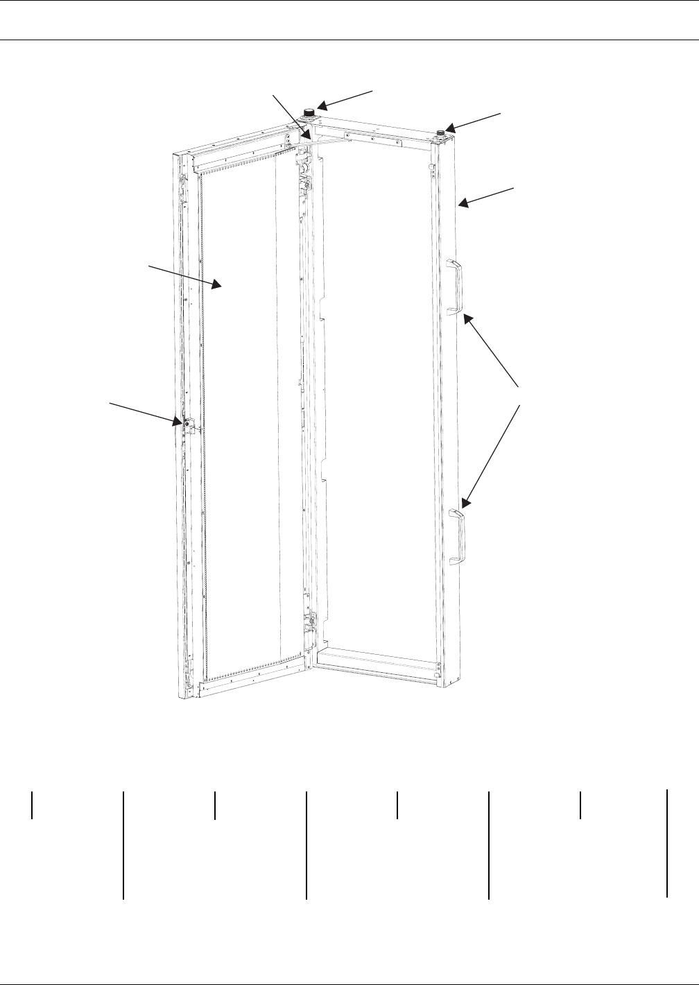
1.0 COMPONENT LOCATIONS AND MODEL NUMBER NOMENCLATURE
Figure 1 Liebert XDR component locations
Figure 2 Liebert XDR model number nomenclature
1. Supply Line
2. Door Safety Catch
3. Return Line
4. Evaporator Coils
5. Locking Door Latch
6. Removable Installation Handles
7. Frame
1
23
4
56
7
XD 20 B
20 = Model SizeLiebert
X-treme
heat
density
system
Example: XDR20B1R — *
R
Rear Cooling Module
—
- = Domestic Packaging
E = Export Packaging
1
1 = Standard
B = Basic Module
*
Revision
level
R
- = Hard-Piping
P = Pre-Charged One-Shot
Coupling
R = Removable Coupling
Introduction
2
2.0 INTRODUCTION
2.1 References
This document must be used together with site specific documentation and documentation for other
parts of the system.
2.2 Pre-Installation Checks
• Check the received materials to be sure all required assemblies and parts have been received. If
you discover any external damage, report it to the shipping company and your local Emerson rep-
resentative.
2.3 Packing List
• User manual (this document)
• Liebert XDR module
2.4 Installation Considerations
The Liebert XDR is designed for attachment to the rear of computer cabinets in the data center. See
4.0 - Mechanical Considerations for details.
2.4.1 Room Preparation
The room should be well-insulated and must have a sealed vapor barrier. The vapor barrier in the
ceiling and walls can be a polyethylene film. Paint on concrete walls and floors should contain either
rubber or plastic.
Outside or fresh air should be kept to a minimum when temperature and humidity must be tightly
controlled. Outside air adds to the cooling, heating, dehumidifying and humidifying loads of the site.
Doors should be properly sealed to minimize leaks and should not contain ventilation grilles.
NOTE
The vapor barrier is the single most important requirement for maintaining environmental
control in the conditioned space.
General Product Information
3
3.0 GENERAL PRODUCT INFORMATION
3.1 Product/System Description
The Liebert XDR is a cooling system for high-density heat loads that mounts on the rear of a
24" x 42U rack (for other sizes consult the factory) and maintains access to the back of the server
rack. Room air is drawn in through the front of the rack and picks up heat from the servers. The coil
captures that heat, cooling the air, which is expelled through the rear of the rack.
The Liebert XDR relies on the rack equipment’s fans to move air across the micro-channel coil. Cap-
tured heat is carried away through pumped R-134a refrigerant supplied by either a Liebert XDP™ or
Liebert XDC™.
The complete cooling system may include other Liebert XD cooling modules, such as the Liebert
XDO™, Liebert XDV™, Liebert XDH™, Liebert XDA™ or Liebert XDCF™ (see Figure 3) and Liebert
XD Flex Piping.
The Liebert XDR is not expected to produce any condensation because of its location, usually in the
data center. A condensate pan is provided as a precaution. It does not have a drain fitting or other
means of being emptied.
Four handles to ease carrying the Liebert XDR are attached at the factory. These should be removed
after the module is attached to the rear of the enclosure. Leaving the handles attached would require
space between the racks. The handles should be retained for use if the Liebert XDR is removed from
the enclosure.
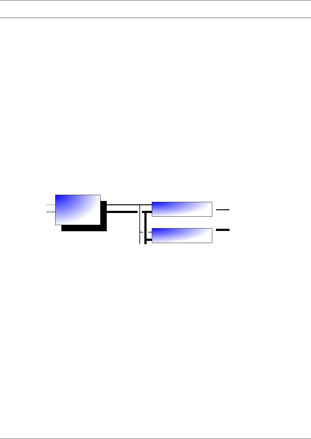
Figure 3 Generic piping layout
3.2 Checking and Unpacking
Upon arrival of the module and before unpacking it, verify that the labeled equipment matches the
bill of lading.
Inspect all items for either visible or concealed damage. Damage should be immediately reported to
the carrier and a damage claim filed with a copy sent to Emerson or to your sales representative. If
you later find any concealed damage, report it to both the shipping company and your local Emerson
representative.
Check to be sure all required assemblies and parts have been received.
The Liebert XDR is shipped in protective packaging and secured to a pallet (see Figure 5). Do not
remove these protective items from the Liebert XDR before it is at the installation location. When
unpacking and handling the Liebert XDR, exercise extra care to prevent damage.
Liebert XDC
or
Liebert XDP
Supply Lines
Return Lines
* Liebert XDCF ; Liebert XDH
Liebert XDO ; Liebert XDR
Liebert XDV
Liebert
XD Cooling Module
Liebert
XD Cooling Module
Pumped
Refrigerant
R134a
*
*
General Product Information
4
3.2.1 Recyclable Packaging
All material used to package this module is recyclable. Please save for future use
or dispose of the material appropriately.
NOTICE
Risk of improper storage. Can cause module damage.
Keep the module indoors and protected from dampness, freezing temperatures and contact
damage.
NOTICE
Risk of damage from forklift. Can cause exterior and/or underside damage.
Keep tines of the forklift level and at a height suitable to fit below the skid.
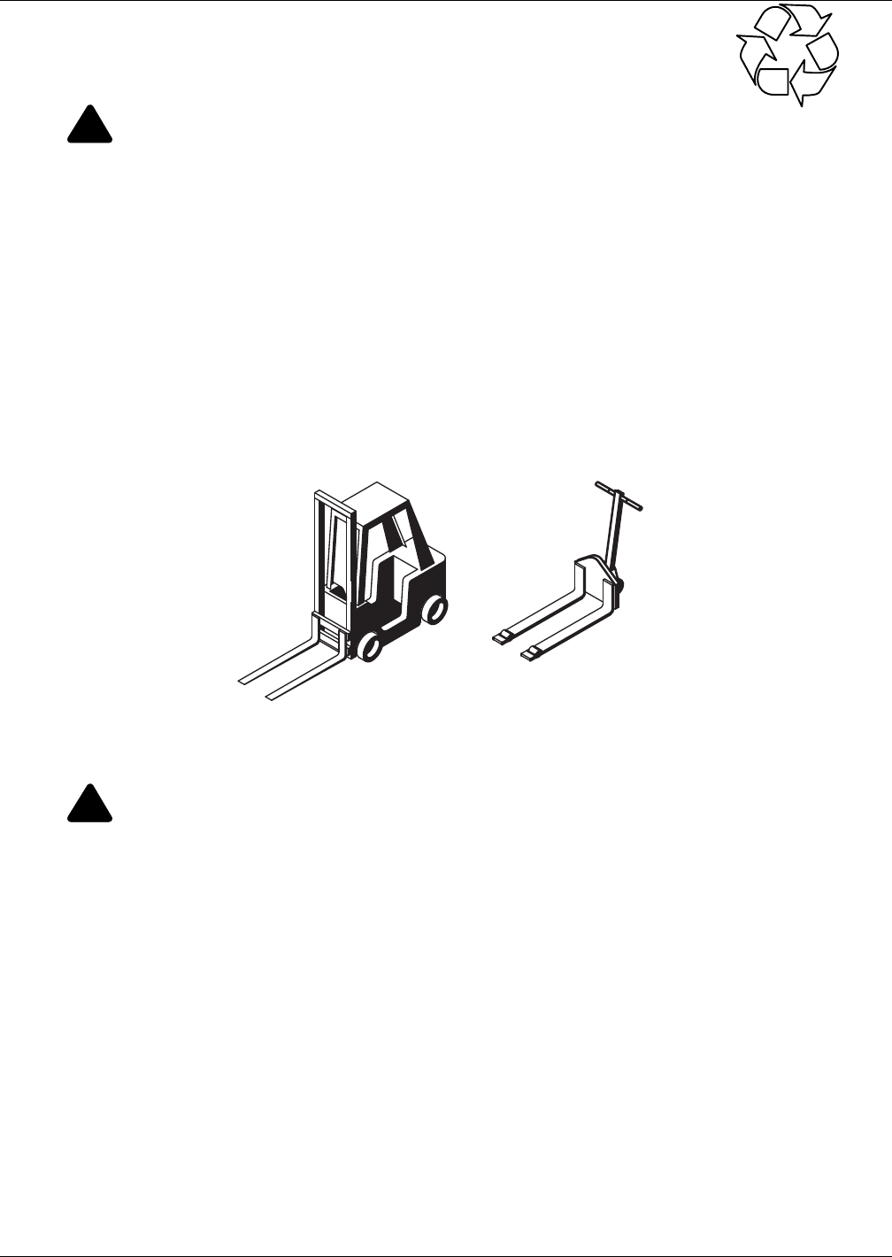
Figure 4 Recommended module handling equipment
3.2.2 Module Handling
When unpacking and handling the module, exercise extra care to prevent damage.
Use a forklift or pallet jack to move the Liebert XDR. If multiple Liebert XDR modules are delivered,
they will be shipped on a pallet with up to four modules. A pallet jack will be required to move these
modules to the installation location.
• If using a forklift or pallet jack, ensure that the fork tine length is suitable to safely move the
packaged module.
• Keep the module in the protective packaging until it has been moved to the installation site.
• When handling and unpacking the module, exercise great care to prevent damage.
• Do not lift the module any higher than 6" (152mm) while moving it. If it must be lifted higher
than 6" (152mm), exercise great care and keep all personnel who are not helping move the module
at least 20 feet (5m) away from the module.
• Do not use module piping to lift or move the Liebert XDR.
!
CAUTION
Risk of sharp edges, splinters and exposed fasteners. Can cause personal injury.
Only properly trained personnel wearing appropriate safety headgear, gloves, shoes and
glasses should attempt to move, lift, remove packaging from, or prepare module for
installation.
!
WARNING
Risk of 130-pound (59 kg) module falling. Can cause equipment damage, personal injury or
death.
Do not leave a Liebert XDR standing unattended on its side or its end without adequate
support to prevent it from falling over. The Liebert XDR must be supported at all times or laid
flat on protective material until it is installed.
Two properly trained and qualified people are required to move the module.
R
Forklift
Pallet Jack

General Product Information
5
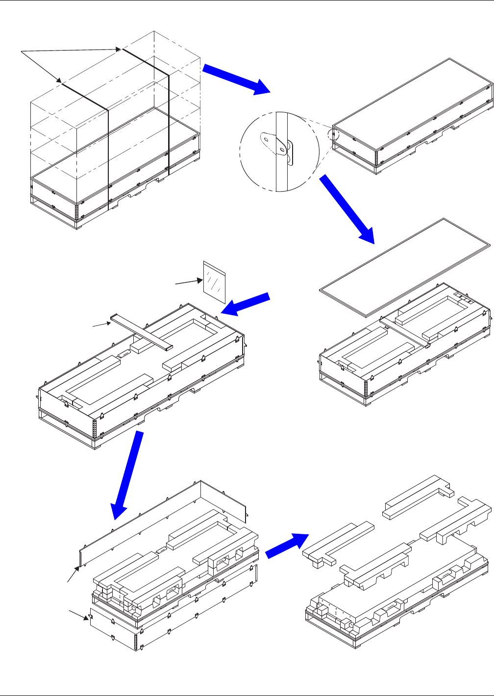
3.2.3 Unpacking the Module
Do not unpack the Liebert XDR before moving it to the installation location. Once at the installation
point:
1. Cut the banding and place all packaged modules on the floor for unpacking.
2. Unbend all metal tabs as shown in Figure 5.
Use any of these tools to unbend the tabs: flat-blade screwdriver, claw hammer, pliers or crowbar.
3. Remove the top cover from the package.
4. Remove the center top brace.
5. Remove and set aside the hardware and key package.
6. Remove side panels from package.
7. Remove top protective foam from the package.
!
WARNING
Risk of 130-pound (59 kg) module falling. Can cause equipment damage, personal injury or
death.
Do not leave a Liebert XDR standing unattended on its side or its end without adequate
support to prevent it from falling over. The Liebert XDR must be supported at all times or laid
flat on protective material until it is installed.
Two properly trained and qualified people are required to move the module.
General Product Information
7
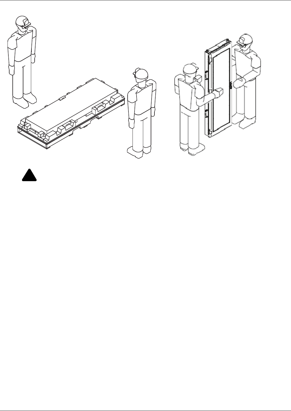
Figure 6 Remove Liebert XDR from pallet
3.2.4 Removing the Liebert XDR from the Pallet
1. Unfold the module bag to expose the Liebert XDR.
2. Compare the serial tag information on the Liebert XDR to the bill of lading information. If the
information does not match the product specified, contact your local sales representative.
3. At least two properly trained and qualified personnel may lift the Liebert XDR off the pallet using
the four handles and stand it upright, supporting the module to keep it from falling.
4. If the Liebert XDR will not be installed immediately, lay a piece of protective material the length
of the module on a flat surface and lay the Liebert XDR on it.
!
WARNING
Risk of 130-pound (59 kg) module falling. Can cause equipment damage, personal injury or
death.
Do not leave a Liebert XDR standing unattended on its side or its end without adequate
support to prevent it from falling over. The Liebert XDR must be supported at all times or laid
flat on protective material until it is installed.
Two properly trained and qualified people are required to move the module.
Two people are required
to remove the module from the pallet
and remove the bag
Mechanical Considerations
8
4.0 MECHANICAL CONSIDERATIONS
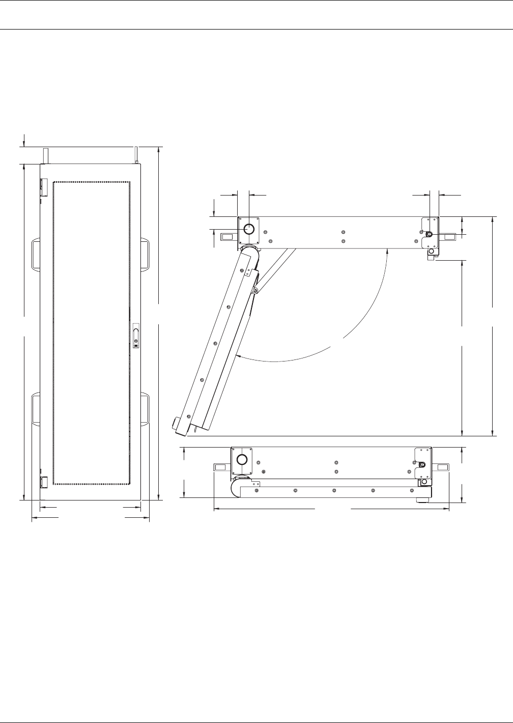
4.1 Liebert XDR Dimensions
The Liebert XDR is engineered to fit on the rear of a rack enclosure measuring approximately
24" x 42U. Consult the factory for other sizes. Figures 7,8 and 9 illustrate the module’s dimensions
and the location of pipes. Figure 11 shows the attachment positions of each module.
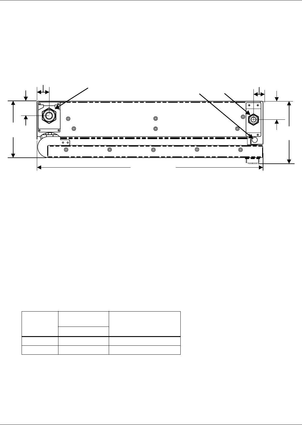
Figure 7 Overall dimensions with hard-piped connections
1-1/2"
(38mm)
4"
(102mm)
78-3/8"
(1991mm)
82-3/8"
(2092mm)
5-7/8"
(149mm)
1-5/16"
(33mm)
20-1/2"
(520mm)
110deg
23-1/2" (597mm)
1-1/8"
(29mm)
27-3/8" (695mm)
6-12"
(165mm)
2-1/8"
(54mm)
25-5/8"
(651mm)
27-3/8"
(695mm)
Piping is not load-bearing and
should never be used to lift or
move the Liebert XDR.
Mechanical Considerations
9
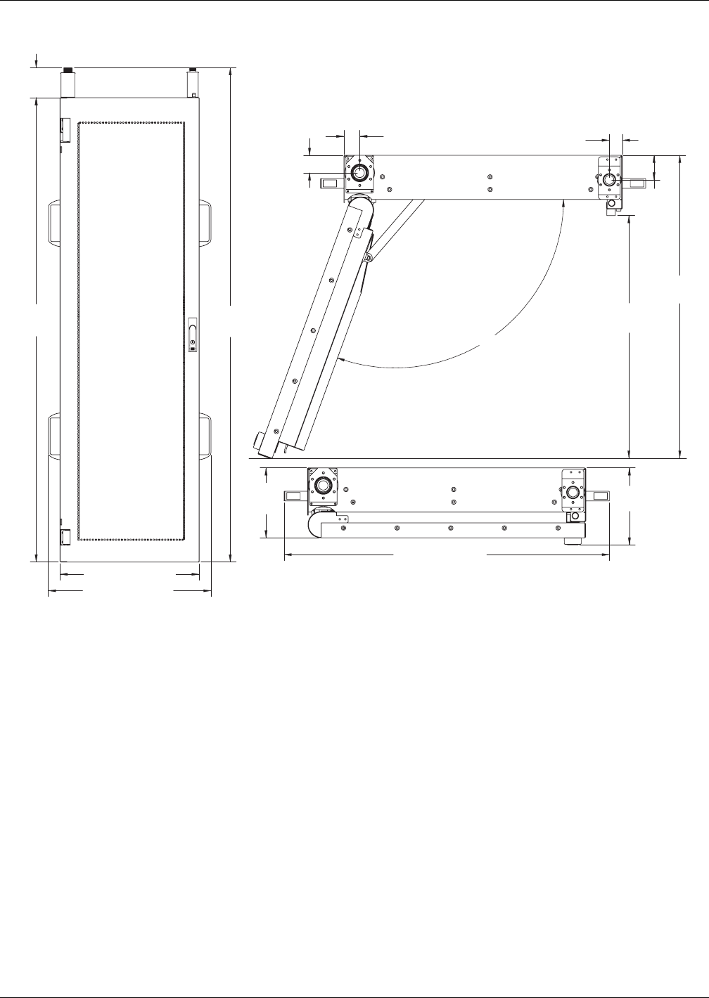
Figure 8 Overall dimensions with one-shot coupling (pre-charged)
1-1/2"
(38mm)
1-5/16"
(34mm)
78-3/8"
(1991mm)
5-1/8"
(130mm)
83-1/2"
(2121mm)
5-7/8"
(149mm)
110deg
23-1/2" (597mm)
27-3/8" (695mm)
6-1/2"
(165mm)
27-3/8" (695mm)
20-1/2"
(520mm)
1-1/8"
(29mm)
2-1/8"
(54mm)
25-5/8"
(651mm)
Piping is not load-bearing and
should never be used to lift or
move the Liebert XDR.
Mechanical Considerations
10
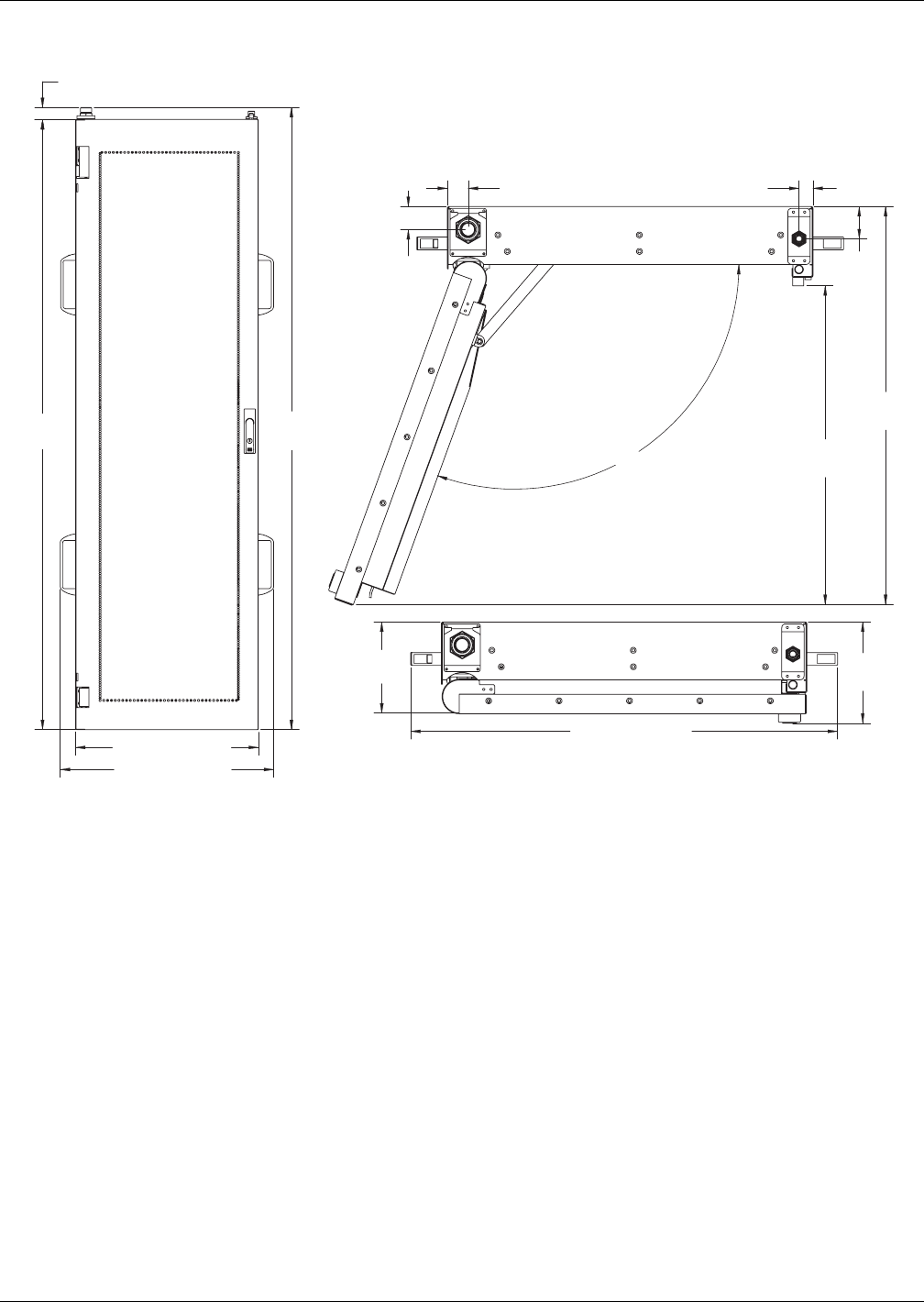
Figure 9 Overall dimensions with removable coupling
4.2 Determining Placement in the Conditioned Space
Refer to site-specific drawings for exact placement. Efficient cooling of the rack equipment depends on
proper placement of equipment, proper use of blanking plates in any voids in the rack, and good cable
management.
The Liebert XDR is engineered to fit the rear of computer enclosure cabinets. Figures 7,8 and 9
illustrate the module's dimensions and the location of pipes.
Ensure that there is 25.6" (649mm) clearance in the rear to allow the door to open fully.
1-1/2"
(38mm)
1-5/16"
(33mm)
1-1/2"
(38mm)
78-3/8"
(1991mm)
80"
(2032mm)
5-7/8"
(149mm)
20-1/2"
(520mm)
110deg
23-1/2" (597mm)
7/8"
(22mm)
27-3/8" (695mm)
6-1/2"
(165mm)
2-1/8"
(54mm)
25-5/8"
(651mm)
27-3/8" (695mm)
Piping is not load-bearing and
should never be used to lift or
move the Liebert XDR.
Mechanical Considerations
11
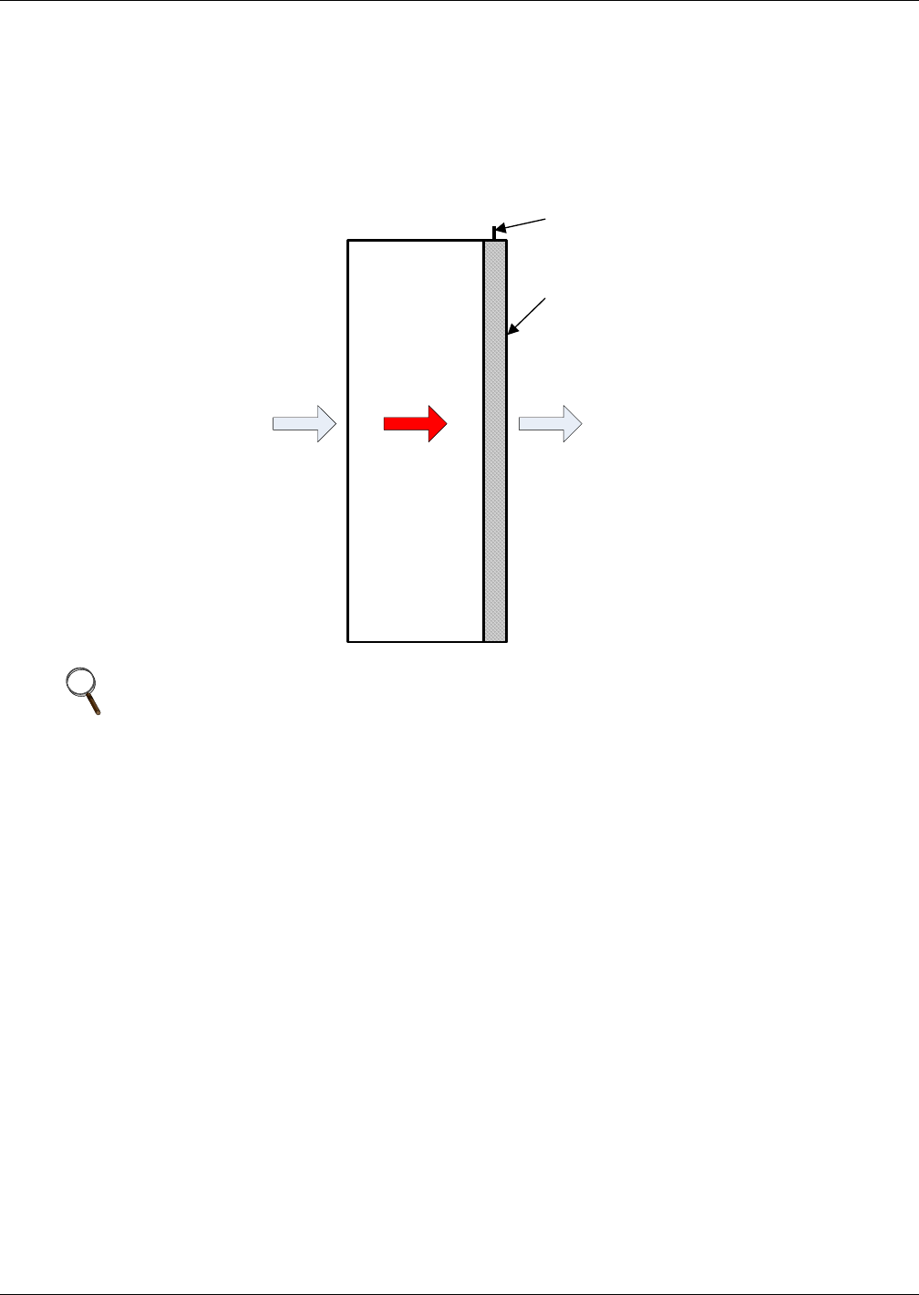
4.3 Airflow
The server fans draw air into the equipment enclosure. After heated the air, the server fans force the
air across the Liebert XDR’s two coils. The Liebert XDR has a low air-side pressure drop (similar to a
rack with perforated doors). The server fans within the rack create sufficient airflow to move the air.
Figure 10 Generic airflow diagram
Efficient cooling of rack equipment depends on proper use of blanking plates in any voids in the rack
and good cable management. Keep the Liebert XDR’s coils clear of any obstructions that may block
the airflow.
Each of the Liebert XDR’s coils removes approximately half the load. For even cooling in partially
filled racks, servers should be evenly spaced and blanking plates should be installed on unused rack
spaces to prevent recirculation of heated air.
NOTE
Air bypass and recirculation can severely reduce the cooling effectiveness of the Liebert XDR.
Blanking plates must be installed in any voids in the rack to prevent air bypass and air
recirculation. Contact the factory for further information. Refer to the user manual supplied
with the rack the Liebert XDR is mounted on.
Liebert XDR
Front
of
Rack
Rear
of
Rack
Refrigerant
Connections
Critical
Equipment
Enclosure /Rack
Shown from Side
Installation
12
5.0 INSTALLATION
5.1 Installing the Rack-Mounting Kit onto the Rack
The Liebert XDR module mounts on the rear of the rack using a mounting kit. The mounting kit
secures the Liebert XDR's frame to the rack. Two rails are attached to the rear of the rack with
M6 x 12 bolts. The number of bolts can vary depending on the rack.
Before beginning to attach the rack-mounting brackets to the rack, remove the rear door from the
rack. Refer to the rack’s installation manual for details.
1. Insert and screw in the M6 x 12mm bolts that shipped with the Rack Connecting Bracket.
2. Tighten the bolts with a 10mm wrench.
5.2 Mounting the Liebert XDR on the Rack-Mounting Kit
The rack-mounting brackets must be mounted on the rack before the Liebert XDR can be installed.
1. Thread one of the provided M6x12 bolts into the top threaded hole of each rail attached to the
rack.
2. Use fingers or a 10mm wrench to tighten the bolts, leaving a 1/8" (3-4mm) gap between the bolt
heads and the rail. This gap is necessary to allow the door to fit over the bolts and hang safely on
the rack.
3. With another person, lift the Liebert XDR by the handles on the sides, match the two keyhole
slots near the top of the Liebert XDR frame to the bolts and hang the Liebert XDR on the rack.
4. Thread the remaining bolts through the holes in the frame and into the mounting rails.
5. Tighten all of the bolts snugly with a 10mm wrench.
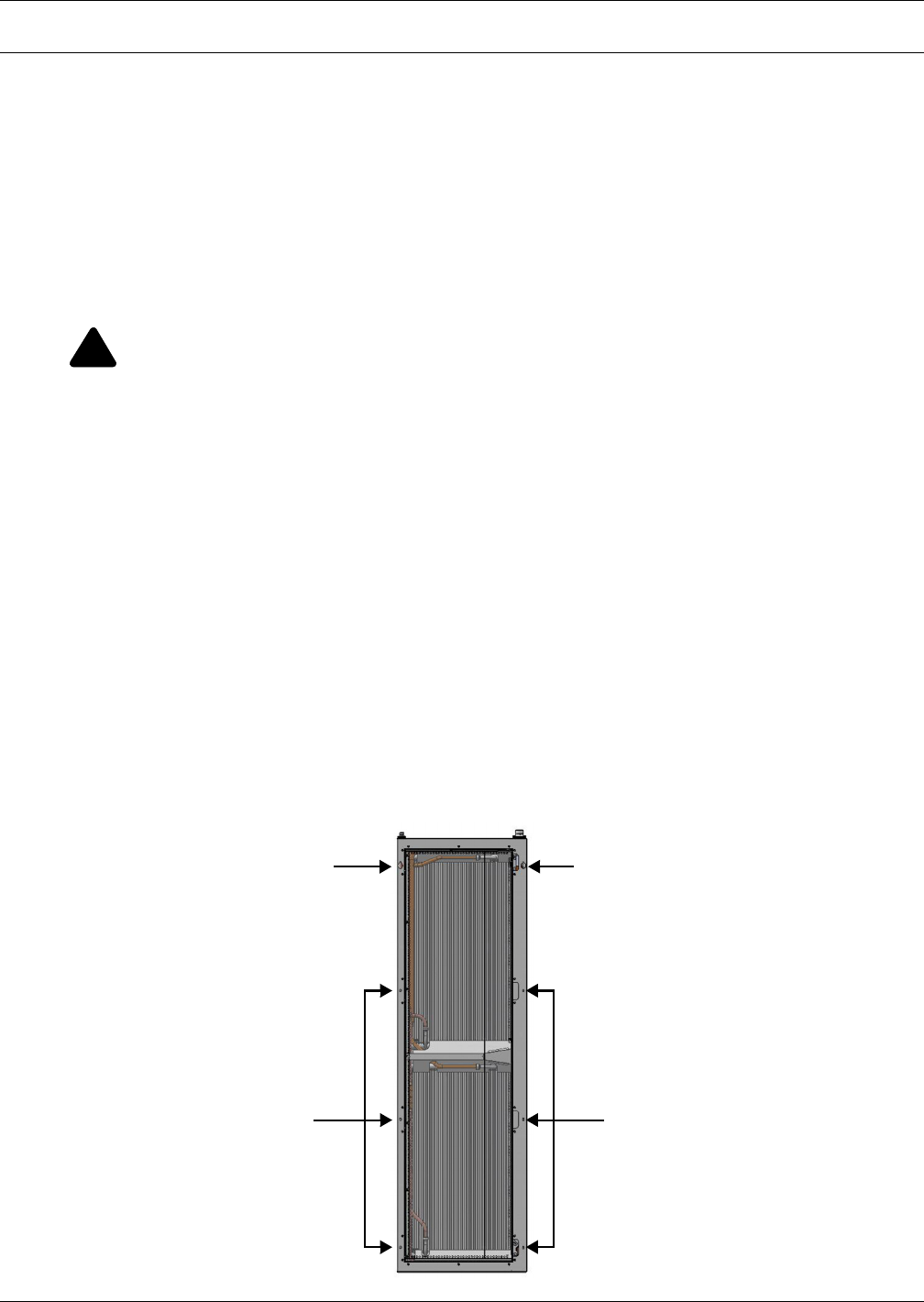
Figure 11 Liebert XDR mounting locations
!
WARNING
Risk of 130-pound (59 kg) module falling or causing cabinet to tip over. Can cause equipment
damage, personal injury or death.
• Read all instructions before beginning.
• Use caution when installing the Liebert XDR on an equipment cabinet, particularly a cabi-
net with little equipment installed. Lack of weight in the cabinet could cause it to tip while
the Liebert XDR is being installed.
• Two properly trained and qualified people are required to handle the Liebert XDR.
• Do not move a cabinet with a Liebert XDR installed on it.
Bolt Holes
(3 on Each Side)
Piping is not load-bearing
and should never be used to
lift or move the Liebert XDR.
Keyhole Slot
(One on Each Side)
Bolt Holes
(3 on Each Side)
Keyhole Slot
(One on Each Side)

Installation
13
5.3 Door Safety Catch
The door safety catch prevents the door from opening beyond 110°. When the door is fully open, the
safety catch will hold door in place. To release the door, push up on the door catch and close the door.
Piping
14
6.0 PIPING
Refer to site-specific drawings for general locations of the piping connections. The drawings should
specify where the piping connects to the Liebert XDR.
6.1 European Union Fluorinated Greenhouse Gas Requirements
Stationary air conditioning, refrigeration, heat pump equipment and stationary fire protection sys-
tems in the European Community market and operating with fluorinated greenhouse gases (f-gas),
such as R407C, R-134a, R410A, must comply with the F-Gas Regulation: (EC) No. 842/2006 (F-gas).
The regulation prohibits, among other actions, venting fluorinated greenhouse gases to the atmo-
sphere.
The F-Gas Regulation requires operators to use all measures that are technically feasible and do not
entail disproportionate cost to prevent leakage of these gases, to test for leakage regularly and to
recover f-gas before disposing of equipment, as well as during service and maintenance.
Refer to the full regulation for additional details.
6.2 System Connection Configuration
If possible, connect the Liebert XDR modules to Liebert XDPs or Liebert XDCs in an interlaced
configuration (see Figure 12). In an interlaced configuration, half the cooling modules in an aisle are
connected to one Liebert XDP or Liebert XDC and the other half in that aisle are connected to another
Liebert XDP or Liebert XDC. Interlacing the connection piping will keep half the Liebert XDR
modules operating and maintain cooling in the conditioned space should one of the Liebert XDP or
Liebert XDC units fail.
However, if this is not possible, connect the Liebert XDR modules in a non-interlaced configuration
(see Figure 13).
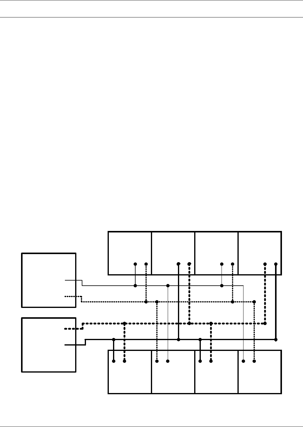
Figure 12 Typical Liebert XDR piping—interlaced connections
Return
Supply
Liebert XDP /
Liebert XDC A
Liebert
XDR A
Liebert
XDR B
TOP VIEW
Return
Supply
Liebert XDP /
Liebert XDC B
NOTE: Line size does NOT
indicate pipe size difference .
Liebert
XDR B
Liebert
XDR B
Liebert
XDR B
Liebert
XDR A
Liebert
XDR A
Liebert
XDR A
DRAWING IS
NOT TO SCALE
Piping
15
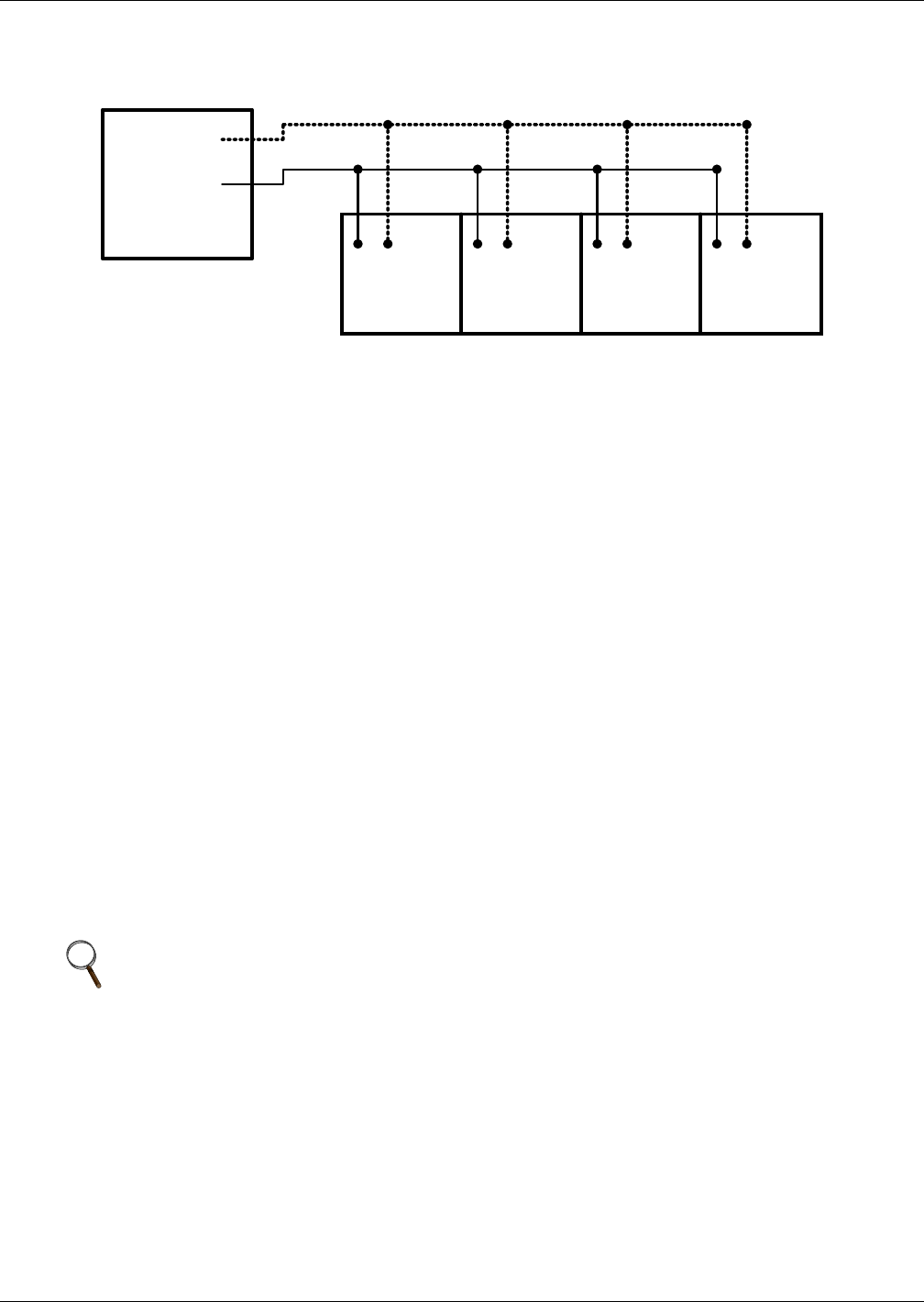
Figure 13 Typical Liebert XDR piping—non-interlaced connection
6.3 Connection Methods and Points
Refer to site specific drawings for general locations of the piping connections. For Liebert XDR con-
nection locations, refer also to Figures 14,17 and 21.
The assembly and connection means used for piping in the Liebert XD system are the same as those
used in conventional refrigeration systems. Observe all standard practices during installation and
startup to prevent damage and contamination. All piping must be ASTM Type ACR copper.
The Liebert XDR has supply and return piping access on the top of each module. Supply piping con-
nection is 1/2" OD copper pipe, and return piping connection is 7/8" OD copper. The hard-piped Lie-
bert XDR has a low-pressure nitrogen holding charge.
Both supply and return couplings may be supplied with optional one-shot couplings. These couplings
contain pressurized R-134a refrigerant inside the Liebert XDR.
For Liebert XDRs with removable couplings, the supply piping connection is 1/2" OD and the return
piping connection is 7/8" OD. Both the Liebert XDR and the Liebert XD Flex Pipe with removable cou-
plings have a low-pressure nitrogen holding charge.
6.4 Insulation
To minimize the possibility of condensation, insulate all piping between the Liebert XDR and the Lie-
bert XDP or Liebert XDC.
6.5 Venting the Holding Charge for Hard-Piped or Removable Liebert XD Flex Pipe
Couplings
The Liebert XDR in either hard-piped configuration or with removable couplings is shipped with a
low-pressure holding charge (about 30 psi) of nitrogen to prevent oxidation and moisture. This must be
vented from the refrigeration circuit before removing the copper cap.
To vent the holding charge:
1. Find the Schrader valve that retains the nitrogen holding charge in the Liebert XDR. The valve is
inside the rear door, on the supply line (see Figure 14 for hard-piped connections and Figure 22
for removable couplings).
2. Vent the holding charge in the circuit by depressing the pin in the Schrader valve on the supply
line.
3. Replace and secure the cap on the Schrader valve that was opened.
NOTE
This procedure is for modules with hard-piped or removable couplings ONLY. Do not vent a
pre-charged Liebert XDR or pre-charged Liebert XD Flex Piping.
TOP VIEW
Return
Supply
Liebert XDP /
Liebert XDC A
Liebert XDR A Liebert XDR A Liebert XDR A Liebert XDR A
DRAWING IS
NOT TO SCALE
Piping
16
6.5.1 Brazing Preparations
The assembly and connection means used for piping in the Liebert XD system are similar to those
used for conventional refrigeration systems. All piping should be installed with high-temperature
brazed joints. Soft soldering is not recommended.
After the holding charge has been vented and before brazing, wrap a wet rag around the copper con-
nections before removing the caps to prevent internal component damage. A torch can be used to
remove the caps over the ends of the supply and return lines.
During brazing, the lines must be filled with flowing dry nitrogen to prevent excessive oxidation and scale
formation inside the piping. Prevailing good refrigeration practices must be employed for piping supports,
leak testing, dehydration and charging. Failure to use good system practices may result in damage to the
system. Refer to the ASHRAE refrigeration handbook for general good-practice refrigeration.
6.5.2 Recommended Piping Size
Connect the main pipes between the Liebert XDR branch piping and the Liebert XDP or Liebert XDC
according to Table 1. Elbows and restrictions must be minimized to ensure good fluid flow.
See Table 1 below for recommended pipe sizes and Figure 3 for piping segment locations.
See Figure 14 for piping recommendations for hard-piping between the Liebert XDR and the header
system.
6.6 Hard-Piped Connection Sizes
The supply piping for the refrigeration circuit is 1/2" OD copper pipe. The return piping for the circuit
is 7/8" OD copper.
The Liebert XDR modules that are intended for hard-piping connections will have copper caps sol-
dered in place and a holding charge of nitrogen.
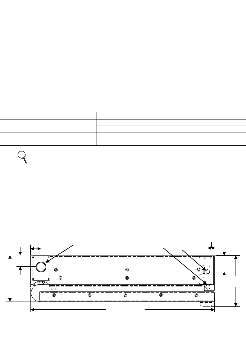
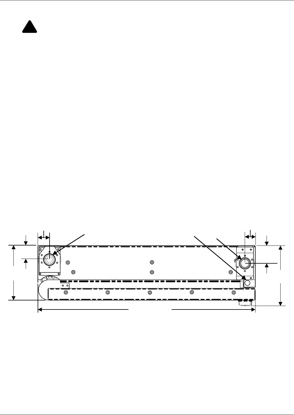
Figure 14 Piping location and connection sizes—modules with hard-piped connections
Table 1 Branch piping sizes for pumped refrigerant loop
Pipe Function Size / Equivalent Pipe Length
From Liebert XDR supply to supply line of
Liebert XDP/Liebert XDC
1/2" OD (0.430" ID) for lengths up to 10 feet (3m)
7/8" OD (0.545" ID) for lengths over 10 feet but less than 25 feet (3-7.6m)
From Liebert XDR return to return line of
Liebert XDP/Liebert XDC
7/8" OD (0.545" ID) for lengths up to 10 feet (3m)
1-1/8" OD (1.025" ID) for lengths over 10 but less than 25 feet (3-7.6m)
NOTE
To minimize the amount of pumped refrigerant required, do NOT oversize the piping.
5-7/8"
(149mm)
1-1/ 2"
(38mm) 2-1/8"
(54mm)
1-1/8"
(29mm)
6-1/2"
(165mm)
TOP VIEW
(Rear of Cabinet ) Refrigerant
Supply Line
Schrader Valve
23-1/2" (597mm)
Refrigerant
Return Line
1-5/16"
(33mm)
Piping
17
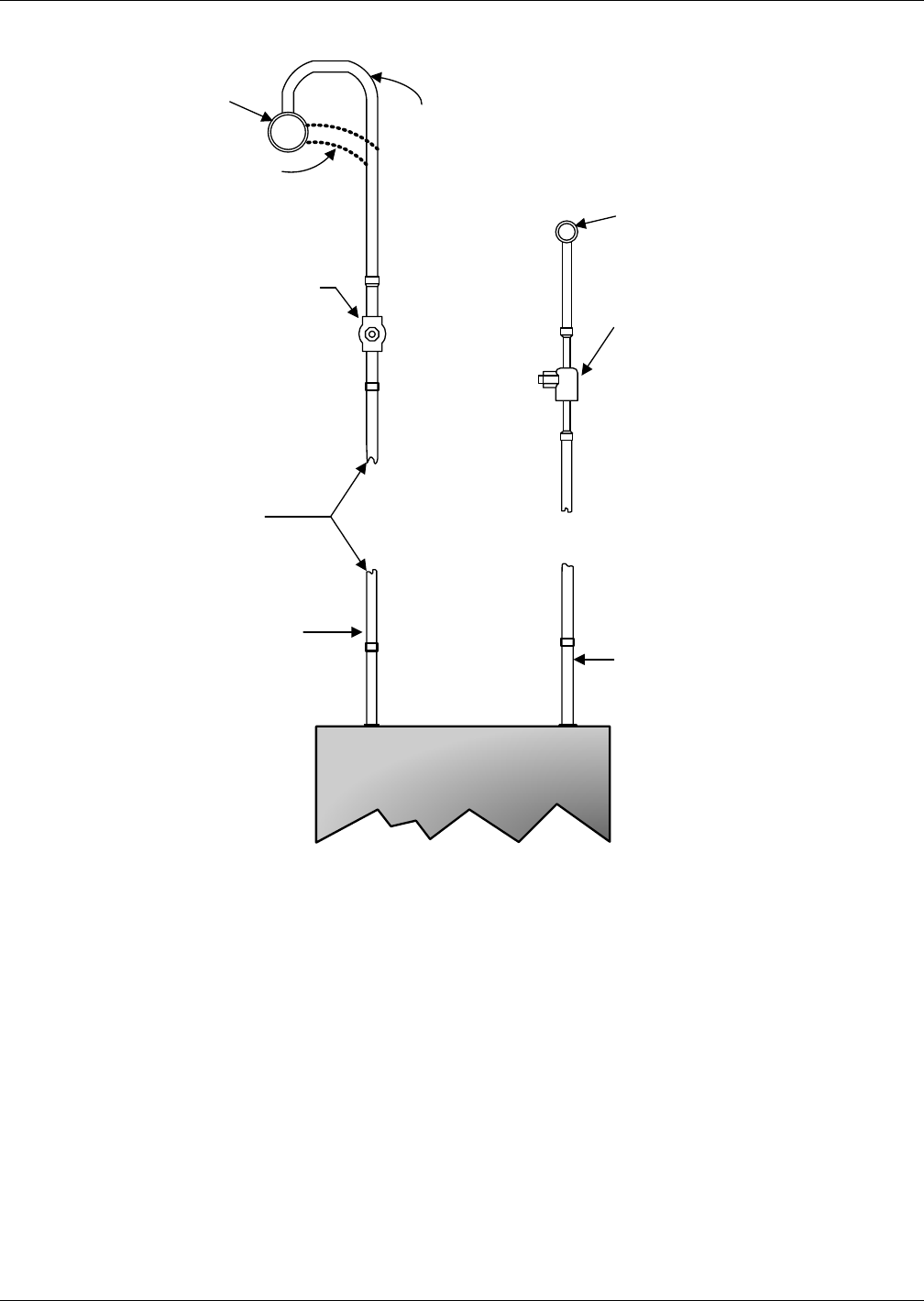
Figure 15 Hard pipe connection diagram
6.6.1 Leak-Checking and Evacuation
Refer to the Liebert XDC or Liebert XDP user manual for procedures for evacuation, leak check,
charging and startup.
6.6.2 Header System
The Liebert XDR module system with optional flexible piping requires use of the Liebert XD prefabri-
cated piping assembly. The prefabricated piping is compatible with the Liebert XD Flex Pipe required
to attach to the Liebert XDR modules. For the details on piping connection locations, see Figure 14.
For additional information, refer to the Liebert X-treme Density System Design Manual, SL-16655,
available at the Liebert Web site: www.liebert.com
Top of
Liebert XDR
and
Equipment
Rack
Return Main
(seen from end )
2-1/8" O.D.
or 2-5/8" O.D. Recommended Arc
Acceptable
Arc
Copper Tubing
Total length of each line
from Liebert XDR to
Main not to exceed 72"
(1829 mm)
7/8” Refrigerant -Grade
Full-Port Ball Valve
Field-Supplied and
Field-Installed
Return from
Cooling Module
Supply Main
(seen from end )
1-1/8" O.D.
or 1-3/8" O.D.
1/2” Refrigerant -Grade
Full-Port Ball Valve
Field-Supplied and
Field- Installed
Supply
to Cooling
Module
Rear of
Equipment Rack
Refer to Table 1 for details.
Piping
18
6.7 Field Installation of Liebert XD Flex Pipe Kit on Liebert XDR
If you are not performing a service installation or a field-retrofit, skip this section and proceed with
the instructions in 6.7.2 - Connect a Liebert XDR with One-Shot Couplings to Liebert XD Flex
Pipe.
Liebert XD Flex Pipe kits are available in lengths of 4, 6, 8 and 10 feet (1.2, 1.8, 2.4 and 3 meters).
Connection style to the module end may be straight or 90 degrees with one-shot or removable cou-
plings. Connection to the prefab piping assembly is a threaded coupling. For data on acquiring the
correct kit for your installation, see Table 8.
The Liebert XD Flex Pipe should be connected to the Liebert XD module then to the header system to
ease installation and prevent twisting the flex pipe.
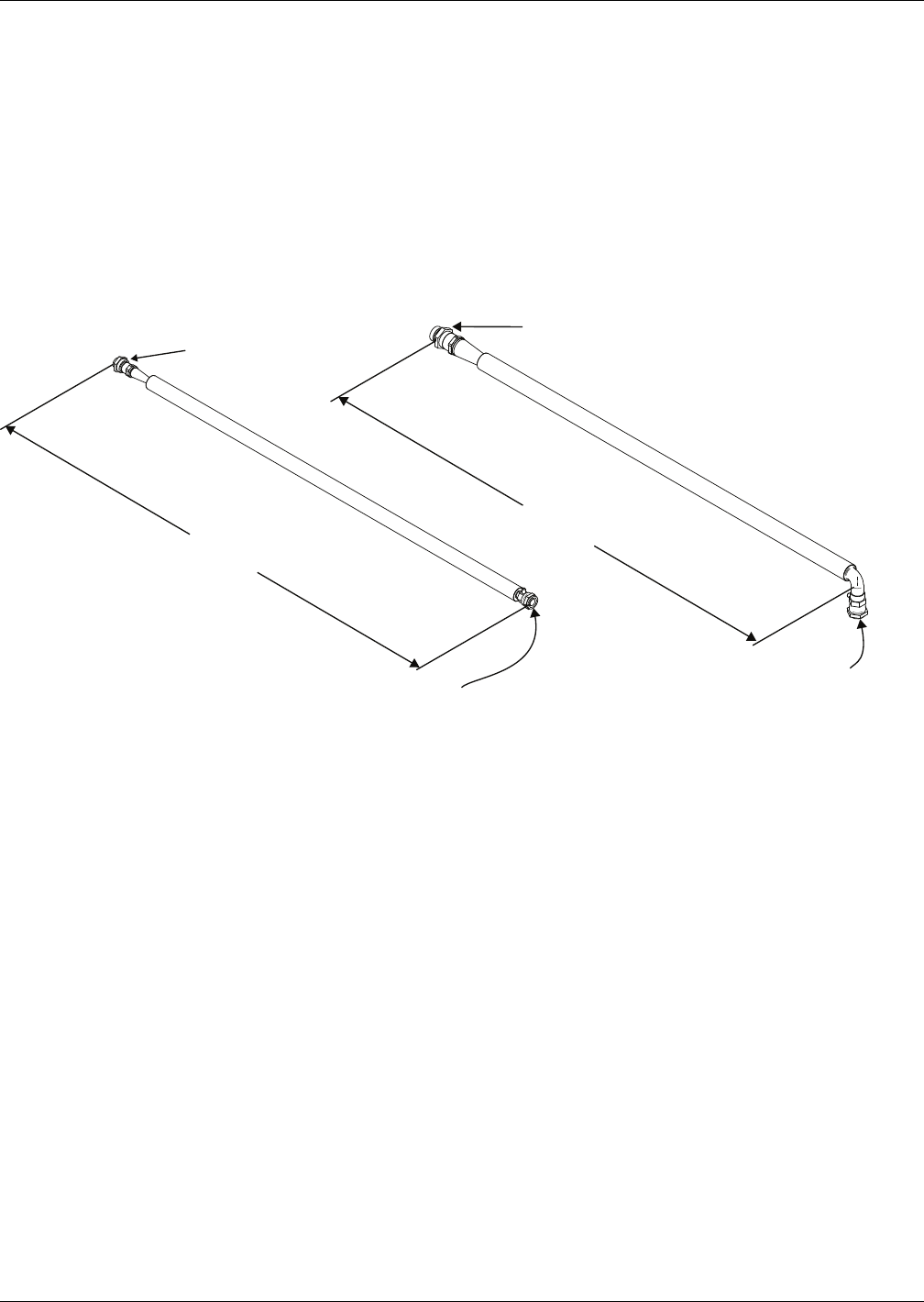
Figure 16 Liebert XD Flex Pipe dimensions—straight and 90-degree connections
Connection
to Prefabricated
Piping assembly
Straight Connection
90-Degree
Connection
Connection to Liebert XD Cooling Module
Length
4, 6, 8 or 10 feet
(1.2, 1.8, 2.4 or 3 meters)
Connection
to Prefabricated
Piping assembly
90° Connection to Liebert XD
Cooling Module
DPN000780
Length
4, 6, 8 or 10 feet
(1.2, 1.8, 2.4 or 3 meters)
Piping
19
6.7.1 Connecting Methods—One-Shot Couplings for Pre-Charged Refrigerant Option
Liebert XDRs with the pre-charged option are equipped with one-shot couplings on the supply and
return fittings. These contain a charge of R-134a refrigerant under pressure within the module. This
charge must not be vented.
Do not remove the pipe caps or plugs before the module is ready for connection to Liebert XD Piping.
Do not disconnect one-shot Liebert XD Flex Pipes after they have been connected.
The assembly and connection means used for piping in the Liebert XD system are the same as those
used in conventional refrigeration systems. Observe all standard practices during installation and
startup to prevent damage and contamination.
Both supply and return fittings may be supplied with optional, one-shot couplings. These fittings con-
tain pressurized R-134a refrigerant inside the Liebert XDR.
If the module includes the optional, factory-installed, one-shot style couplings, proceed with 6.7.2 -
Connect a Liebert XDR with One-Shot Couplings to Liebert XD Flex Pipe and see Figure 17.
If the module does not include Liebert Flex Pipes, refer to 6.5 - Venting the Holding Charge for
Hard-Piped or Removable Liebert XD Flex Pipe Couplings.
Figure 17 Piping location and connection sizes—modules with pre-charged modules
!
CAUTION
Risk of sudden refrigerant discharge. Can cause loss of charge and minor injury.
If the optional pre-charged option is chosen, the Liebert XDR is shipped with a full charge of
R-134a refrigerant under pressure. Do not remove the pipe caps or plugs before the module is
ready for connection to Liebert XD Piping.
Supply and return fittings on the pre-charged Liebert XDR modules are one-shot couplings.
Do not disconnect one-shot couplings after they have been connected. Disconnection will
release pressurized R-134a refrigerant from the Liebert XDR.
5-7/8"
(149mm)
1-1/ 2"
(38mm) 2-1/8"
(54mm)
1-1/8"
(29mm)
6-1/ 2"
(165mm)
TOP VIEW
(Rear of Cabinet)
Refrigerant
Supply Line
Schrader Valve
(Do Not Vent)
23-1/2" (597mm)
Refrigerant
Return Line
1-5/16"
(33mm)
Piping
20
6.7.2 Connect a Liebert XDR with One-Shot Couplings to Liebert XD Flex Pipe
NOTICE
Risk of improper reuse of Liebert XD Flex Pipes with one-shot couplings. Can cause
refrigerant leaks.
Liebert XD Flex Pipes with one-shot couplings must not be removed from the Liebert XDR
unless they are being replaced with Liebert XD Flex Pipes with one-shot couplings. Do not
reuse Liebert XD Flex Pipes with one-shot couplings. Reuse may result in refrigerant leaks.
Tools Required
• Two adjustable wrenches with a maximum adjustment size of 2 inches
• One torque wrench, half-inch drive (see Table 2 for sizes)
• Refrigerant oil
1. Check the Liebert XD Flex Pipe for proper length.
2. Remove the protector cap and plug from the connections and carefully wipe the couplings and
threaded surfaces clean.
3. Use a small applicator brush saturated with refrigerant oil to lubricate the entire surface of the
diaphragm and the O-ring. Refer to Figure 18.
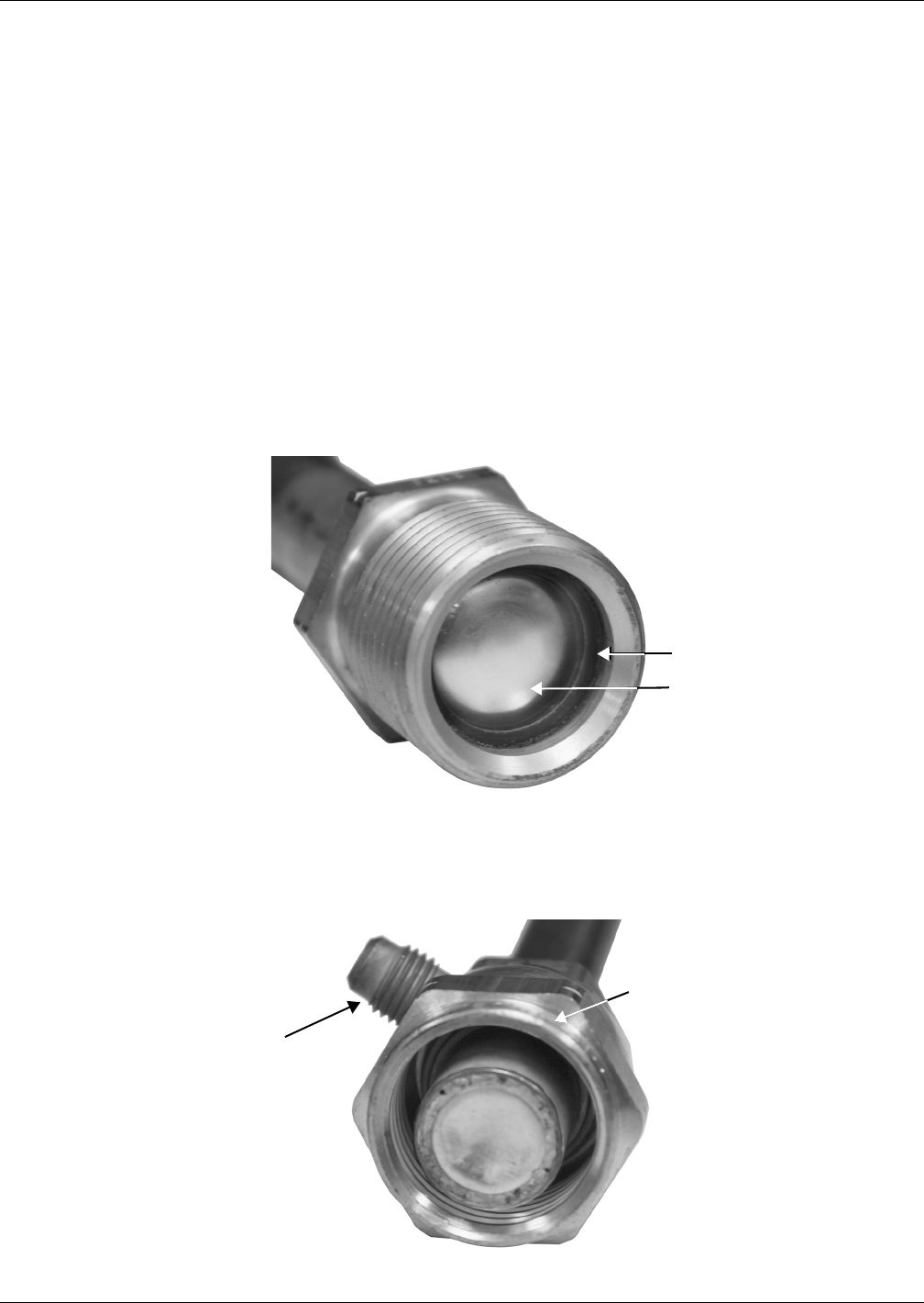
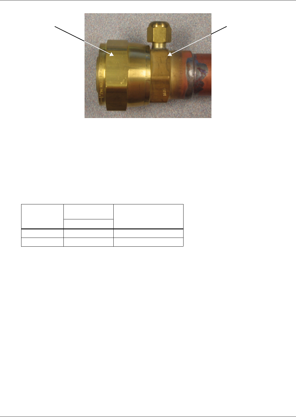
Figure 18 Male coupling on Liebert XD cooling module
If refrigerant oil is not used, an alternate lubricant for this application is a refrigerant-compatible
silicone grease product, such as Dow Corning DC200/60,000 cst.
4. Thread the coupling halves together by hand to ensure that the threads mate properly. Ensure
that the Schrader valve is oriented so that it is accessible for service.
Figure 19 Female one-shot coupling Liebert Flex Pipe: Schrader valve location
Oil Rubber Seal
and Face of Diaphragm
Coupling Size
Marking on Lip
of Coupling
Schrader
Valve
Piping
21
Figure 20 Hex body, union nut on one-shot coupling
NOTICE
Risk of improper tightening. Can cause equipment damage.
It is imperative that the brass body on the Liebert XD Flex Pipe coupling does not rotate while
the union nut is being tightened. If the brass body rotates, it may damage the Liebert XD Flex
Pipe.
5. Hold the brass body of the Liebert XD Flex Pipe with a wrench so that it does not rotate and use
the torque wrench to tighten the union nut to the proper value shown in Table 2.
If a torque wrench is not available, continue with the steps below.
6. Tighten the union nut on the Liebert XD Flex Pipe to the coupling on the module with the proper-
sized wrench until a definite resistance is felt, metal-to-metal contact.
7. Use a marker or pen to draw a line lengthwise across the module coupling to the Liebert XD Flex
Pipe. The line should parallel the Liebert XD Flex Pipe.
8. Tighten the nuts an additional one (1) wrench flat (60°), judging the amount by the mark drawn
in Step 7.
Table 2 Torque and wrench size for connecting Liebert XDR with one-shot couplings to
Liebert XD Flex Pipe
Coupling
Size
Wrench Sizes,
in. (mm) Torque, Union Nut
Only, ft-lb (Nm)
Union Nut
#10 (Supply) 1-5/16 (34) 35-45 (13.5-6.2)
#12 (Return) 1-3/8 (35) 50-60 (67.8-88.1)
Hex BodyUnion Nut
Piping
22
6.7.3 Connection Methods—Removable Couplings
The assembly and connection means used for piping in the Liebert XD system are the same as those
used in conventional refrigeration systems. Observe all standard practices during installation and
startup to prevent damage and contamination.
Both supply and return fittings may be supplied with optional, removable couplings.
Figure 21 Piping location and connection sizes—modules with removable couplings
6.7.4 Connect Liebert XD Flex Pipe with Removable Coupling to a Liebert XD Cooling Module
Tools Required
• One adjustable wrench with a maximum adjustment size of 2 inches
• One torque wrench, half-inch drive (see Table 3 for sizes)
1. Check the Liebert XD Flex Pipe for proper length.
2. Remove the protector plugs from the Liebert XD Flex Pipe.
3. Remove the protector cap from the couplings on the module.
4. Wipe the fittings and threaded surfaces clean of particles and other foreign substances.
5. Verify the O-ring is in place on the module coupling.
Should additional O-rings be required, refer to Table 4.
6. Place the Liebert Flex Pipe assembly so that the flat face of the flange on the Liebert XD Flex Pipe
coupling comes into contact with the O-ring on the module coupling.
7. Thread the coupling halves together by hand to ensure that the threads mate properly.
If a torque wrench is not available, continue with the steps below.
8. Hold the Liebert XD Flex Pipe so that is does not rotate and use the torque wrench to tighten the
union nut to the proper value shown in Table 3.
9. Tighten the union nut on the Liebert XD Flex Pipe to the coupling on the module with the
adjustable wrench until a definite resistance is felt.
10. Use a marker or pen to draw a line lengthwise across the module coupling to the Liebert XD Flex
Pipe. The line should parallel the Liebert XD Flex Pipe.
11. Tighten the nuts an additional quarter-turn, judging the amount by the mark drawn in Step 10.
Table 3 Torque and wrench sizes for connecting Liebert Flex Pipe to the Liebert XDR with
removable couplings
Coupling
Size, in.
Wrench Size, in.
(mm) Torque, Union Nut
Only, ft-lb (Nm)
Union Nut
1/2 (Supply) 15/16 (24) 40 (55)
1 (Return) 1-5/8 (41) 110 (150)
TOP VIEW
(Rear of Cabinet )
23-1/2" (597mm)
1-5/16"
(33mm) Refrigerant
Return Line Schrader Valve
Refrigerant
Supply Line
1-1/2"
(38mm)
7/8"
(22mm)
6-1/2"
(165mm)
2-1/8"
(54mm)
5-7/8"
(149 mm)
Piping
23
Figure 22 Removable couplings
6.7.5 Connect a Liebert XDR with Liebert XD Flex Pipe to a Liebert XD System
NOTICE
Risk of refrigerant loss. Can cause environmental pollution and equipment malfunction.
Before connecting the Liebert XDR with Liebert XD Flex Pipe to the prefabricated piping
mains, check the whole system for leaks.
Check the Liebert XDR to ensure that the module has no refrigerant leaks.
Read all instructions before beginning installation.
Tools Required
• One adjustable wrench with a maximum adjustment size of 2 inches
• One torque wrench, half-inch drive
• Crowsfoot (supplied with Liebert XDP and Liebert XDC)
• Liebert XDP or Liebert XDC user manual
1. Determine the port location of the supply and return piping overhead.
2. Make sure the service valve for each port is closed
3. Remove caps from only the required ports. Do not remove caps from the unused ports.
4. Remove the pipe plugs that are supplied on the Liebert XD Flex Pipe.
5. Inspect both halves of the coupling and remove any foreign contamination from the sealing
surfaces and threads before connecting the fittings.
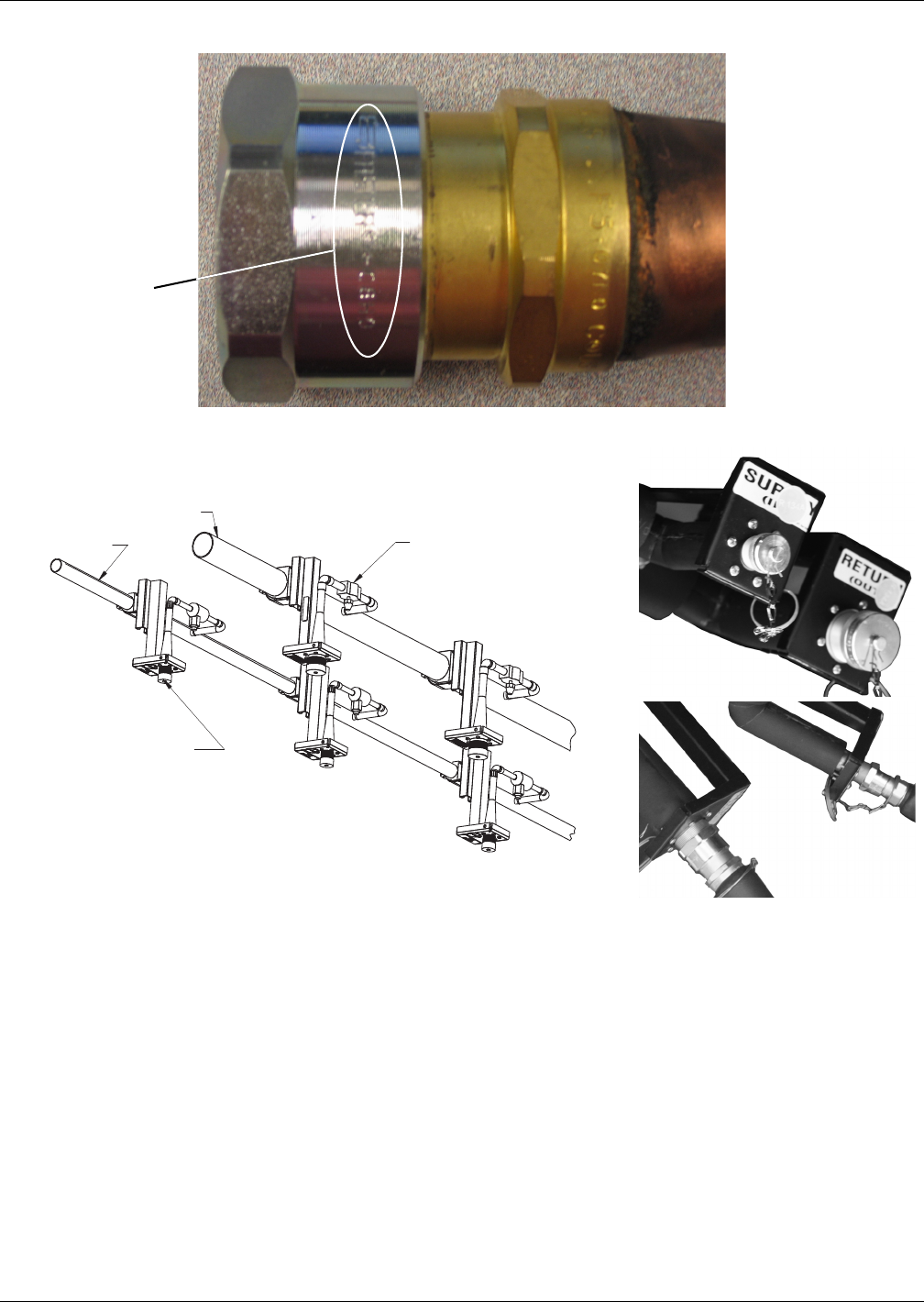
6. Determine the coupling size by locating the number scribed on the Liebert XD Flex Pipe coupling.
See Figure 23.
Table 4 O-ring part number
Liebert Part # Size, in. Fitting
192917P1 1/2 FD57-1224-08-10
192917P2 5/8 FD57-1224-10-11
192917P3 7/8 FD57-1224-14-12
NOTE
Check the entire system for leaks before connecting the Liebert XDR with Liebert XD Flex Pipe
to the prefabricated piping mains.
Read all instructions before beginning installation.
NOTE
This operation requires two or more people.
Removable Female Coupling on
the end of Liebert XD Flex Pipe
On the Liebert
Flex Pipe On the Liebert
XD Module
Flange
O-Ring
Piping
24
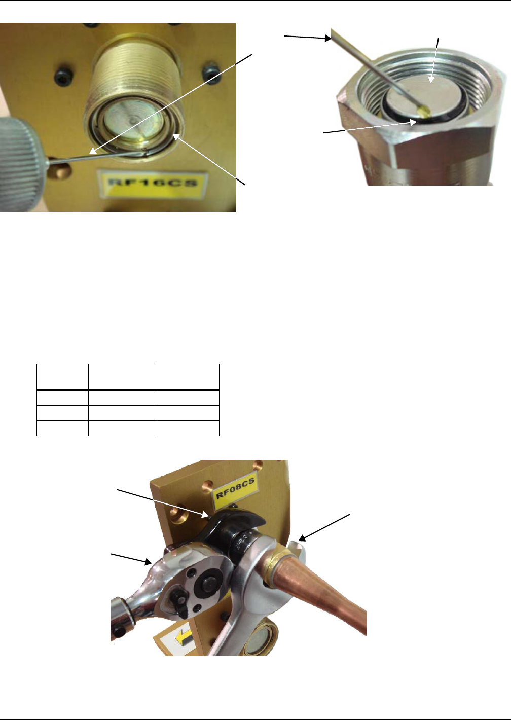
Figure 23 Coupling size indicator
Figure 24 Liebert XD prefabricated piping assembly
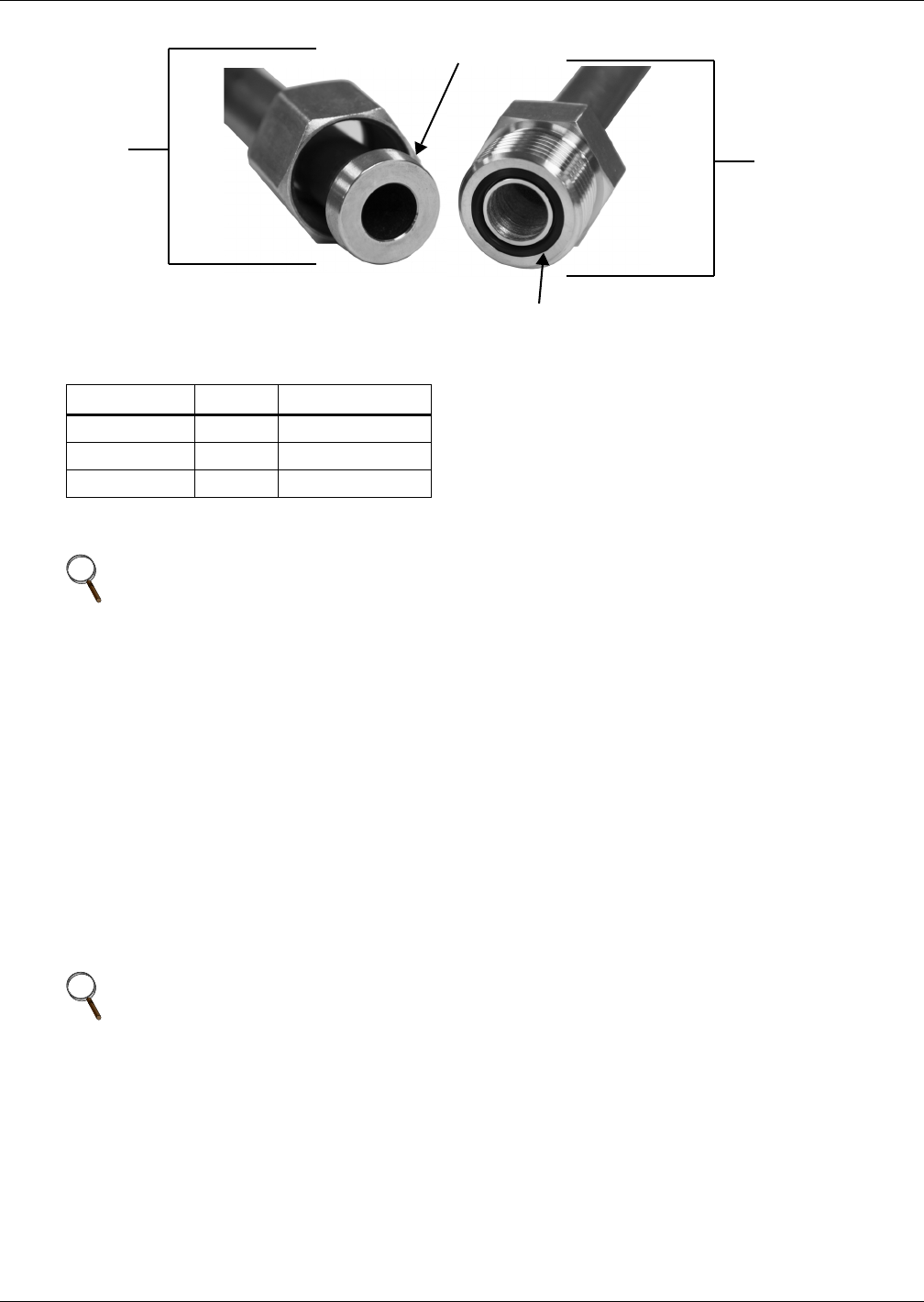
7. Use mineral oil or polyol ester oil to lubricate the face of the poppet valve and the seal around the
poppet valve on the female connector (on the Liebert XD Flex Pipe) (see Figure 25).
8. Apply mineral oil or polyol ester oil to the stainless steel delta ring on the male connector (header
port connector) (see Figure 25).
Coupling size
indicator
Threaded Cap
(Typical)
Supply Main Service Valve, typical
(all ports)
Return Main
Headers, Capped
Headers, Connected
Piping
25
Figure 25 Oil rings on header and Liebert XD Flex Pipe connectors
9. Thread the union nut of the Liebert XD Flex Pipe coupling onto the port coupling to ensure the
threads mate properly.
10. Using the wrench arrangement shown in Figure 26, torque the couplings to the values in
Table 5.
NOTICE
Risk of twisted or kinked piping. Can cause flow restriction or leaks.
It is imperative that the brass body of the Liebert XD Flex Pipe coupling does not rotate while
the couplings are being tightened. Failing to do so may damage the female coupling.
Figure 26 Wrench arrangement for tightening couplings
Table 5 Torque for connecting Liebert XD Flex Pipe to prefabricated piping
Coupling
Size
Crowsfoot
Size, in (mm)
Torque,
ft-lb (Nm)
RF08 1-3/16 (30) 25.8 (30-35)
RF12 1-5/8 (41) 48.0 (60-65)
RF16 1-31/32 (50) 62.7 (80-85)
Stainless Steel Delta Ring
on Header Port Connector
Rubber Ring
Around Poppet
Valve Face
Oil
Applicator
Spout
Poppet Valve Face
Crowsfoot
Torque Wrench
Wrench holding brass body of
female coupling stationary
to prevent it from turning
Piping
26
Figure 27 Detail view of Liebert XD Flex Pipe and prefabricated piping port
11. Repeat Steps 3 through 10 for the remaining Liebert XD Flex Pipe.
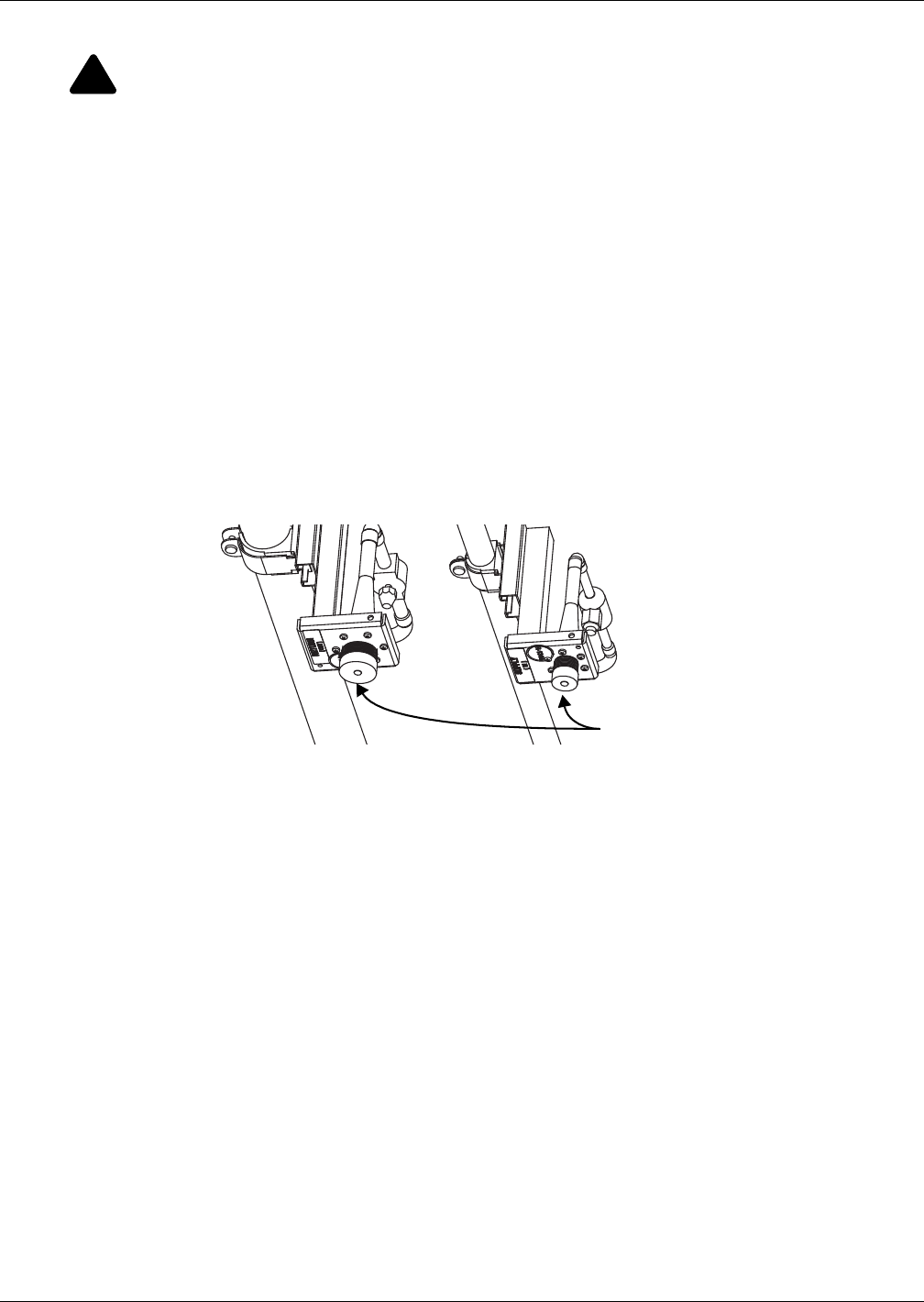
12. For a Liebert XDR module with removable couplings, open the return and then supply service
valves. If the Liebert XDR is pre-charged DO NOT open either of the service valves.
13. Refer to the Liebert XDC or Liebert XDP user manual for procedures for evacuation,
leak check, charging and startup.
If adding a one-shot, pre-charged Liebert XD module with one-shot pre-charged Liebert
XD Flex Pipes to an operational Liebert XD system, after connecting to the header system:
1. Open the return service valve.
2. Open the supply service valve.
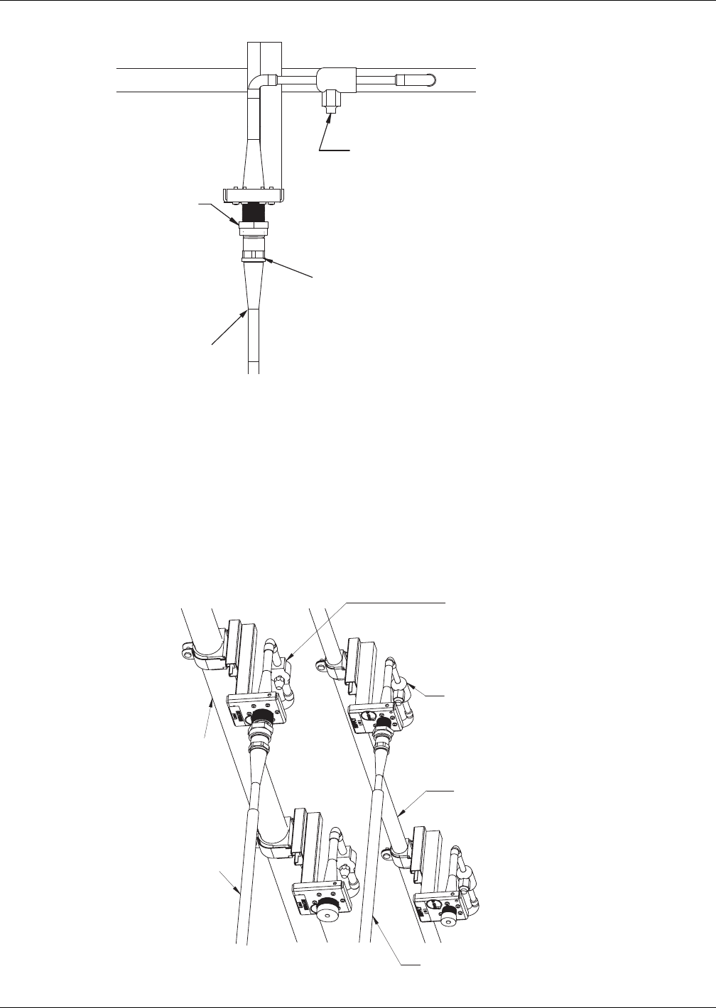
Figure 28 Liebert XD prefabricated piping assembly and Liebert XD Flex Pipe
Tighten with
torque wrench.
DO NOT
OVERTIGHTEN!
Service Valve
Note: Make sure the valve
is closed before attaching
Liebert XD Flex Pipe to the system.
Hold threaded coupler
here with a wrench to keep
the brass body on
the female connector
from rotating while tightening
collar with a torque wrench.
Flex Pipe
Return Service Valve
Make sure valve is
open after system
leak check
Supply Service Valve.
Make sure valve is
open after system
leak check
Return Liebert
XD Flex Pipe from
Liebert XDR
Supply Liebert XD Flex Pipe
from Liebert XDR
Return
Main
Supply Main
Piping
27
6.7.6 Disconnect a Liebert XD Flex Pipe from a Liebert XD System
Tools Required
• Two adjustable wrenches with a maximum adjustment size of 2 inches
1. Close the service valve in the supply line.
2. Ensure there is airflow across the coil.
3. Wait two minutes for the refrigerant to flow out of the module.
4. Close the service valve in the return line.
5. Loosen the Liebert XD Flex Pipe coupling from the header port coupling. This requires a wrench.
Refer to Figure 27.
The Liebert XD Flex Pipe coupling must be held stationary while the union nut on the coupling is
being loosened.
6. Disconnect the coupling.
7. Place the protective dust cap on the port.
8. Place the protective plug back on the Liebert XD Flex Pipe.
9. Repeat Steps 5 through 7 for the remaining Liebert XD Flex Pipe.
Figure 29 Piping mains without Liebert XD Flex Pipe
!
CAUTION
Risk of sudden discharge of pressurized refrigerant. Can cause equipment damage or injury.
Do not disconnect threaded refrigerant couplings at the module cabinet end without relieving
system pressure. Reclaim any refrigerant during removal of module from system.
Dust caps attach here
Piping
28
6.7.7 Disconnecting the Liebert XD Flex Pipe from the Liebert XDR
NOTICE
Risk of improper reuse of Liebert XD Flex Pipes with one-shot connections. Can cause
refrigerant leaks.
Liebert XD Flex Pipes with one-shot connections must not be removed from the Liebert XDR
unless they are being replaced with Liebert XD Flex Pipes with one-shot couplings. Do not
reuse Liebert XD Flex Pipes with one-shot connections. Reuse may result in refrigerant leaks.
Tools Required
• Two adjustable wrenches with a maximum adjustment size of 2 inches
1. Reclaim the refrigerant in the Liebert XD Flex Pipe and in the module by attaching a refrigerant
reclaim device to the Schrader valve. For help finding the Schrader valve, see Figures 14,17
and 21.
2. Hold the Liebert XD Flex Pipe so it does not rotate.
For the Liebert XD Flex Pipe with one-shot couplings, additionally, hold the brass body of the cou-
pling so it does not rotate while loosening the couplings. Failing to do so may cause damage.
3. Loosen the Liebert XD Flex Pipe coupling from the module with a wrench.
4. Replace the dust plug on the Liebert XD Flex Pipe.
5. Replace the dust cap on the Liebert XD module.
6. Lay the Liebert XD Flex Pipe with removable couplings aside where it will not be damaged.
Discard or recycle the one-shot Liebert XD Flex Pipes.
NOTICE
Risk of permanent damage to the Liebert XD Flex Pipes. Do not fold or bend pipe tightly.
6.7.8 Removing the Liebert XDR from a Cabinet
1. Reinstall the four removable installation handles.
2. Loosen the bolts holding the Liebert XDR on the cabinet.
3. With the help of another person, lift the Liebert XDR from the cabinet or hanging bracket onto a
stable surface.
!
WARNING
Risk of 130-pound (59 kg) module falling. Can cause equipment damage, personal injury or
death.
Removing a Liebert XDR from above a cabinet will require two properly trained and qualified
people. Read all instructions before beginning.

Installation Checklist and System Fill for Startup
29
7.0 INSTALLATION CHECKLIST AND SYSTEM FILL FOR STARTUP
7.1 Checklist for Proper Installation
___ 1. Liebert XDR modules are securely attached to the cabinet and aligned properly with the rack.
___ 2. Check to ensure there are no obstructions that prevent the Liebert XDR from opening.
___ 3. Piping from Liebert XDP or Liebert XDC, with isolation valves, is properly connected to each
Liebert XDR module.
___ 4. Liebert XD Flex Pipe couplings to prefabricated header assembly are secure and according to
specifications.
___ 5. System checked for leakage.
___ 6. Check the R-134a refrigerant charge (see the user manual for either the Liebert XDP,
SL-16671 or the Liebert XDC, SL-16644; each is available on the Liebert Web site,
www.liebert.com).
___ 7. Run system and verify that the Liebert XDP or Liebert XDC and the Liebert XDR modules
operate properly.
___ 8. Piping is insulated.
7.2 Charging with Refrigerant
The Liebert XD system must be completely installed before it is charged with refrigerant. After
installation is complete, refer to the Liebert XDP or Liebert XDC user manual for instructions on
charging Liebert XD modules with refrigerant and the starting of the system. The complete Liebert
XD system includes all Liebert XD cooling modules, a Liebert XDC or Liebert XDP and any other con-
nected equipment.

Starting the Liebert XD System
30
8.0 STARTING THE LIEBERT XD SYSTEM
Refer to the user manual for the refrigerant supply unit, either a Liebert XDP or Liebert XDC, for
details on starting the system. The Liebert XDP user manual is SL-16644 and the Liebert XDC user
manual is SL-16671. The user manuals were supplied with the units and are available on the Liebert
Web site, www.liebert.com

Maintenance
31
9.0 MAINTENANCE
Minimal maintenance is required to keep the Liebert XDR operating at optimal levels. The module
should be cleaned and checked for damage. Suggested maintenance includes:
• Cooling fins—Clean any dust and debris from the cooling fins, taking care not to bend them.
9.1 Fluorinated Greenhouse Gas Requirements
Stationary air conditioning, refrigeration, heat pump equipment and stationary fire protection sys-
tems in the European Community market and operating with fluorinated greenhouse gases (f-gas),
such as R407C, R134a, R410A, must comply with the F-Gas Regulation: (EC) No. 842/2006 (F-gas).
The regulation prohibits, among other actions, venting fluorinated greenhouse gases to the atmo-
sphere.
The F-Gas Regulation requires operators to use all measures that are technically feasible and do not
entail disproportionate cost to prevent leakage of these gases, to test for leakage regularly and to
recover f-gas during equipment service and maintenance and before disposing of equipment.
Refer to the full regulation for additional details.
Specifications
32
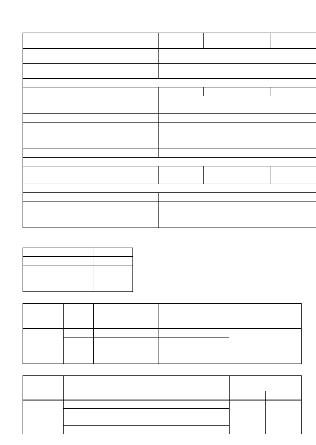
10.0 SPECIFICATIONS
Table 6 Liebert XDR specifications
Models XDR20B1- * XDR20B1P *
(Pre-Charged R-134a) XDR20B1R *
Cooling Capacity, Nominal,
rated at 104ºF (40°C) EAT & 2400ft3/m (68m3/m) 20.5 kW (5.8 tons)
Conditions 55°F (13°C) entering fluid temperature
50°F (10°C) or lower dew point
Dimensions, inches (mm)
Height, Including Pipe Connections 82-3/8 (2093) 83-1/2 (2121) 80 (2032)
Width With Handles Attached 27-3/8 (695)
Handles Removed 23-1/2 (597)
Depth 6-1/2 (165)
Shipping Length 90 (2286)
Shipping Width 30-1/2 (775)
Shipping Depth 15-1/2 (394)
Max Shipping Depth (4 modules) 62 (1575)
Weight, lb (kg)
Module Only 130 (59) 133 (60) 130 (59)
Shipping 225 (103) 228 (104) 225 (103)
Pipe Connections
Refrigerant Supply 1/2" OD Type ACR
Refrigerant Return 7/8" OD Type ACR
Exterior Finish Black Matte, Heat-Fused Powder Coat
Safety CSA, CE Approved
* Refer to Figure 2 for the complete part number.
Table 7 Rack mounting kit
Rack Part #
Knurr Miracel 198163G1
Dell PowerEdge 4210 199050G1
HP 10642 199051G1
APC AR3100 199054G1
Table 8 Liebert XD Flex Pipe one-shot assemblies, supply and return
Description Length
ft (m)
Liebert P/N
Straight Connection
Assembly
Liebert P/N
90-Degree
Connection Assembly
Minimum Bend Radius
in (mm)
Supply Return
Liebert XD
Flex Pipe Kit
10 (3.0) 186566G2 186565G2
7 (178) 9 (229)
8 (2.5) 186566G3 186565G3
6 (1.8) 186566G1 186565G1
4 (1.2) 186566G4 186565G4
Table 9 Liebert XD Flex Pipe removable assemblies, supply and return
Description Length
ft (m)
Liebert P/N
Straight Connection
Assembly
Liebert P/N
90-Degree Connection
Assembly
Minimum Bend Radius
in (mm)
Supply Return
Liebert XD
Flex Pipe Kit
10 (3.0) 187865G2 187864G2
7 (178) 9 (229)
8 (2.5) 187865G3 187864G3
6 (1.8) 187865G1 187864G1
4 (1.2) 187865G4 187864G4

Ensuring The High Availability
Of Mission-Critical Data And Applications.
Emerson Network Power, the global leader in enabling business-critical
continuity, ensures network resiliency and adaptability through
a family of technologies—including Liebert power and cooling
technologies—that protect and support business-critical systems.
Liebert solutions employ an adaptive architecture that responds
to changes in criticality, density and capacity. Enterprises benefit
from greater IT system availability, operational flexibility and
reduced capital equipment and operating costs.
While every precaution has been taken to ensure the accuracy
and completeness of this literature, Liebert Corporation assumes no
responsibility and disclaims all liability for damages resulting from use of
this information or for any errors or omissions.
© 2009 Liebert Corporation
All rights reserved throughout the world. Specifications subject to change
without notice.
® Liebert is a registered trademark of Liebert Corporation.
All names referred to are trademarks
or registered trademarks of their respective owners.
Technical Support / Service
Web Site
www.liebert.com
Monitoring
liebert.monitoring@emerson.com
800-222-5877
Outside North America: +00800 1155 4499
Single-Phase UPS & Server Cabinets
liebert.upstech@emerson.com
800-222-5877
Outside North America: +00800 1155 4499
Three-Phase UPS & Power Systems
800-543-2378
Outside North America: 614-841-6598
Environmental Systems
800-543-2778
Outside the United States: 614-888-0246
Locations
United States
1050 Dearborn Drive
P.O. Box 29186
Columbus, OH 43229
Europe
Via Leonardo Da Vinci 8
Zona Industriale Tognana
35028 Piove Di Sacco (PD) Italy
+39 049 9719 111
Fax: +39 049 5841 257
Asia
29/F, The Orient Square Building
F. Ortigas Jr. Road, Ortigas Center
Pasig City 1605
Philippines
+63 2 687 6615
Fax: +63 2 730 9572
Emerson Network Power.
The global leader in enabling Business-Critical Continuity™
EmersonNetworkPower.com
Emerson, Business-Critical Continuity, Emerson Network Power and the Emerson Network Power logo are trademarks of Emerson Electric Co. or one of its affiliated companies.
©2009 Emerson Electric Co.
AC Power
Connectivity
DC Power
Embedded Computing
Embedded Power
Infrastructure Management & Monitoring
Outside Plant
Power Switching & Controls
Precision Cooling
Racks & Integrated Cabinets
Services
Surge Protection
SL-16935_REV02_06-10
