Emerson Netsure 211 Series Ordering Guides
2015-03-30
: Emerson Emerson-Netsure-211-Series-Ordering-Guides-679931 emerson-netsure-211-series-ordering-guides-679931 emerson pdf
Open the PDF directly: View PDF ![]() .
.
Page Count: 105 [warning: Documents this large are best viewed by clicking the View PDF Link!]
- SYSTEM OVERVIEW
- TABLE OF CONTENTS
- LIST DESCRIPTIONS
- List 1: 1RU High by 19” Wide Shelf
- List 2: 1RU High by 23” Wide Shelf
- List 5: 2RU High by 19” Wide Shelf
- List 6: 2RU High by 23” Wide Shelf
- Rectifier Module (500W), P/N 1R48500
- Rectifier Module (1000W), P/N 1R481000
- ACU+ (Advanced Control Unit Plus), P/N 1M820BNA
- SCU+ (Standard Control Unit Plus), P/N 1M521BNA
- List 60: Five (5) Load Lead Assemblies (P/N 535206) for 10A GMT Fuse Positions
- List 61: Eight (8) Load Lead Assemblies (P/N 535206) for 10A GMT Fuse Positions
- List 62: Five (5) Load Lead Assemblies (P/N 540988) for 15A GMT Fuse Positions
- List 65: Shelf Side Battery Cables, P/N 540814
- List 66: Battery Side Battery Cables, P/N 540954
- List 67: Battery Cable, P/N 545709
- List 71: Optional External Battery Cable Assemblywith Anderson Connector for (1) Battery String, P/N 545493
- List 72: Optional External Battery Cable Assemblywith Anderson Connector for (2) Battery Strings, P/N 535124
- List 73: Optional External Battery Cable Assemblywith Anderson Connector for (1) Battery String, P/N 555050
- List 89: Relay Rack Earthquake Anchor Kit, P/N P0987167
- List 90: Optional Temperature Probe,P/N 04118246 (shelf side half) and P/N 04118247 (probe side half, 9 ft. long)
- List 91: Optional Temperature Probe,P/N 04118246 (shelf side half) and P/N 04116740 (probe side half, 30 ft. long)
- List 93: Battery Tray for 23” Relay Rack
- List 94: Battery Tray for 19” Relay Rack
- List BF: Distribution Unit with GMT Fuse Load Distribution Positionsand with Low Voltage Battery Disconnect (LVBD)
- List LF: Distribution Unit with GMT Fuse Load Distribution Positionsand with Low Voltage Load Disconnect (LVLD)
- List NF: Distribution Unit with GMT Fuse Load Distribution Positionsand w/out Low Voltage Disconnect
- List BC: Distribution Unit with GMT Fuse Load Distribution Positions, Circuit BreakerLoad Distribution Positions, and with Low Voltage Battery Disconnect (LVBD)
- List LC: Distribution Unit with GMT Fuse Load Distribution Positions, Circuit BreakerLoad Distribution Positions, and with Low Voltage Load Disconnect (LVLD)
- List NC: Distribution Unit with GMT Fuse Load Distribution Positions, Circuit BreakerLoad Distribution Positions, and w/out Low Voltage Disconnect
- List BA: Distribution Unit with GMT Fuse Load Distribution Positions,Circuit Breaker Load Distribution Positions, Circuit Breaker Battery Disconnect Positions,and with Low Voltage Battery Disconnect (LVBD)
- List LA: Distribution Unit with GMT Fuse Load Distribution Positions,Circuit Breaker Load Distribution Positions, Circuit Breaker Battery Disconnect Positions,and with Low Voltage Load Disconnect (LVLD)
- List NA: Distribution Unit with GMT Fuse Load Distribution Positions,Circuit Breaker Load Distribution Positions, Circuit Breaker Battery Disconnect Positions,and w/out Low Voltage Disconnect
- List BG: Distribution Unit with GMT Fuse Load Distribution Positionsand with Low Voltage Battery Disconnect (LVBD)
- List NG: Distribution Unit with GMT Fuse Load Distribution Positionsand w/out Low Voltage Disconnect
- List KG: Distribution Panel with (20) GMT Fuse Load Distribution Positions
- ACCESSORY DESCRIPTIONS
- Relay Racks
- Mounting and Adapter Kits
- Optional Wall Mount Bracket Kit for Lists 1 and 2, P/N 541285
- Optional Wall Mount Bracket Kit for Lists 1, 2, 5 and 6, P/N 553203
- Optional 19” to 23” 1RU Rack Adapter Kit, P/N 540993
- Optional 19” to 23” 2RU Rack Adapter Kit, P/N 545728
- Optional 19” Rear Cover Kit, P/N 555260
- Optional 3” Projection Mount Kit for List 1, P/N 556828
- Optional 23” Rear Cover Kit, P/N 555261
- Rear Battery Cable Exit Kit P/N 547645
- Distribution Devices
- AC Input Cables and Line Cords
- AC Input Cable Assembly, P/N 535232
- AC Input Line Cord, 208/240VAC, P/N 540946
- AC Input Line Cord, 208/240VAC, P/N 545616
- AC Input Line Cord, 120VAC, P/N 545252
- AC Input Line Cord, 120VAC, P/N 545478
- AC Input Line Cord, 120VAC, P/N 545479
- AC Input Line Cord, 208/240VAC, P/N 545480
- AC Input Line Cord, 120VAC, P/N 545481
- AC Input Line Cord, 208/240VAC, P/N 545553
- AC Input Line Cord, 120VAC, P/N 547525
- AC Input Line Cord, 120VAC, P/N 548457
- AC Input Line Cord, 120/208/240VAC, P/N 548196
- Special Application Digital Input Cable Kit, P/N 554935
- AP6C57EA/EB Ring & Distribution Module
- External Battery Disconnect Unit, P/N 535282
- NetSure™ 211bc Battery Cabinet (Spec. No. 541434)
- NetSure™ 211bc Battery Cabinet (Spec. No. 545534)
- NetSure™ 211bc Battery Cabinet (Spec. No. 545506)
- NetSure™ 211bc Battery Cabinet (Spec. No. 554631)
- SM TEMP Temperature Concentrator (P/N 547490)
- SM Module RS-485 Interface Cable P/N 547674
- PCU Blank Filler Panel, P/N PSK4820R-1
- Anderson Battery Connector
- Digital Input and Relay Output Cables
- Replacement Modules
- Wiring Notes
- Shelf Frame Grounding Stud
- AC Input Branch Circuit Protection and Wiring
- External Alarm and Monitoring Wiring
- Load Distribution Wiring (GMT Fuses) (Lists BG and NG only)
- Load Distribution Wiring (GMT Fuses) (Lists BF, LF, and NF only)
- Load Distribution Wiring (GMT Fuses) (Lists BC, LC, NC, BA, LA, and NA)
- Load Distribution Wiring (Optional Bullet-Nose-Type 6-Position GMT Fuse Module)
- Load Distribution Wiring (Circuit Breakers) (Lists BC, LC, NC, BA, LA, and NA)
- Load Distribution Wiring (GMT Fuses) (List KG)
- CO Ground Wiring (Lists BF, LF, NF, BC, LC, NC, BA, LA, and NA)
- Input Battery Wiring (List BG and NG)
- Input Battery Wiring (to Battery Disconnect Circuit Breakers) (Lists BA, LA, and NA)
- Input Battery Wiring (to Battery Busbars) (Lists BF, LF, NF, BC, LC, and NC)
- Wiring Illustrations
- Shelf Frame Grounding Stud (both 1U and 2U Panels, List 1 and 5 shown)
- AC Input Wiring (Lists 1 and 2)
- AC Input Wiring (Lists 5 and 6)
- External Alarm and Monitoring Wiring (Lists 1 and 2)
- External Alarm and Monitoring Wiring (Lists 5 and 6)
- Load Distribution Wiring (GMT Fuses) (Lists BG and NG installed in a List 1 or 2, List 1 shown)
- Load Distribution Wiring (GMT Fuses) (Lists BF, LF, and NF installed in a List 5 or 6, List 5 shown)
- Load Distribution Wiring (GMT Fuses) (Lists BC, LC, NC, BA, LA, and NA installed in a List 5 or 6, List 5 shown)
- Load Distribution Wiring (Optional Bullet Nose 6-Position GMT Fuse Module)
- Load Distribution Wiring (Circuit Breakers) and CO Ground Wiring (Lists BC, LC, and NC installed in a List 5 or 6, List 5 shown)
- Load Distribution Wiring (Circuit Breakers), Input Battery Wiring (Circuit Breakers),and CO Ground Wiring (Lists BA, LA, and NA installed in a List 5 or 6, List 5 shown)
- Load Distribution Wiring (GMT Fuses) (List KG)
- Input Battery Wiring (Lists BG and NG installed in a List 1 or 2, List 1 shown)
- Input Battery Wiring (Lists BF, LF, NF, BC, LC, and NC installed in a List 1 or 5, List 5 shown)and CO Ground Wiring (Lists BF, LF, and NF installed in a List 1 or 5, List 5 shown)
- SPECIFICATIONS
- PHYSICAL SIZE INFORMATION
- Overall Dimensions – List 1
- Additional Dimensions – List 1 with Wall Mounting Kit (P/N 541285)
- Additional Dimensions – List 1 with Optional 19” Rear Cover Kit, P/N 555260
- Additional Dimensions – List 1 with Optional 3” Projection Mount Kit, P/N 556828
- Overall Dimensions – List 2
- Additional Dimensions – List 2 with Wall Mounting Kit (P/N 541285)
- Additional Dimensions – List 2 with Optional 23” Rear Cover Kit, P/N 555261
- Overall Dimensions – List 5
- Overall Dimensions – List 6
- Additional Dimensions – Lists 1, 2, 5 and 6 with Wall Mounting Kit (P/N 553203)
- Overall Dimensions – List KG
- Overall Dimensions – 19” Battery Tray
- Overall Dimensions – 23” Battery Tray
- BATTERY MANUFACTURER INFORMATION
- RELATED DOCUMENTATION
SAG582136600
System Application Guide
Spec. No. 582136600 (Model 211NGFB)
Issue AU, February 21, 2014
Page 1 of 105
This document is property of Emerson Network Power, Energy Systems, North America, Inc. and contains confidential and proprietary information owned by Emerson Network Power, Energy
Systems, North America, Inc. Any copying, use, or disclosure of it without the written permission of Emerson Network Power, Energy Systems, North America, Inc. is strictly prohibited.
SYSTEM OVERVIEW
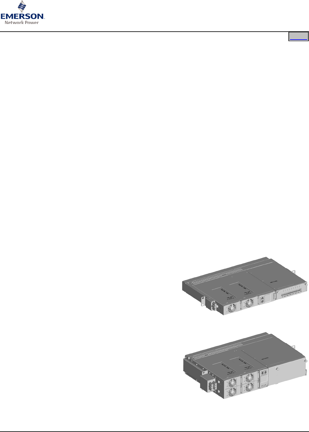
Description: The NetSure™ 211NGFB DC Power System is a complete integrated power system
containing rectifiers, intelligent control, metering, monitoring, and distribution. This power
system consists of the following mounted in a 1RU or 2RU high by 19” or 23” wide shelf.
• 500W or 1000W Rectifier Modules
The 1RU high by 19” wide shelf accommodates
two (2) 500W or 1000W Rectifier Modules.
The 1RU high by 23” wide shelf accommodates
three (3) 500W or 1000W Rectifier Modules.
The 2RU high by 19” wide shelf accommodates
four (4) 500W or 1000W Rectifier Modules.
The 2RU high by 23” wide shelf accommodates
six (6) 500W or 1000W Rectifier Modules.
The Rectifier Modules provide load power, battery float current, and battery recharge
current during normal operating conditions. The Rectifier Modules are designed to
provide constant power. They are designed with the latest patented switch-mode
technology using DSP (Digital Signal Processing) functionality for efficient operation.
This means that, within the normal operating ambient temperature range and input
voltage range, the maximum available output power is a constant 500W or 1000W.
Within these ranges, the Rectifier Modules operate in one of three modes, depending
upon load demands. Transition between modes is completely automatic. If ambient
temperature rises above or input voltage falls below acceptable values, Rectifier
Modules continue to operate but at derated output power levels.
1) Constant Voltage Mode: For any initial output voltage setting from 42 to 58
volts, output voltage remains constant regardless of load. This is the normal
operating condition, in which loads are being supplied and batteries are float
charged. Rectifier Modules operate in the Constant Voltage Mode unless load
increases to the point where
the product of load current and
output voltage is approximately
500W or 1000W.
2) Constant Power Mode: As
load increases above
approximately 500W or 1000W
(non-adjustable), output current
continues to increase, but
output voltage decreases as
required to maintain constant
output power. Rectifier
Modules operate in the
Constant Power Mode unless
load continues to increase to
the point where the current limit
setting is reached.
3) Constant Current Mode: If
load increases above the
current limit setting, output
voltage decreases linearly to
maintain output current at
current limit.
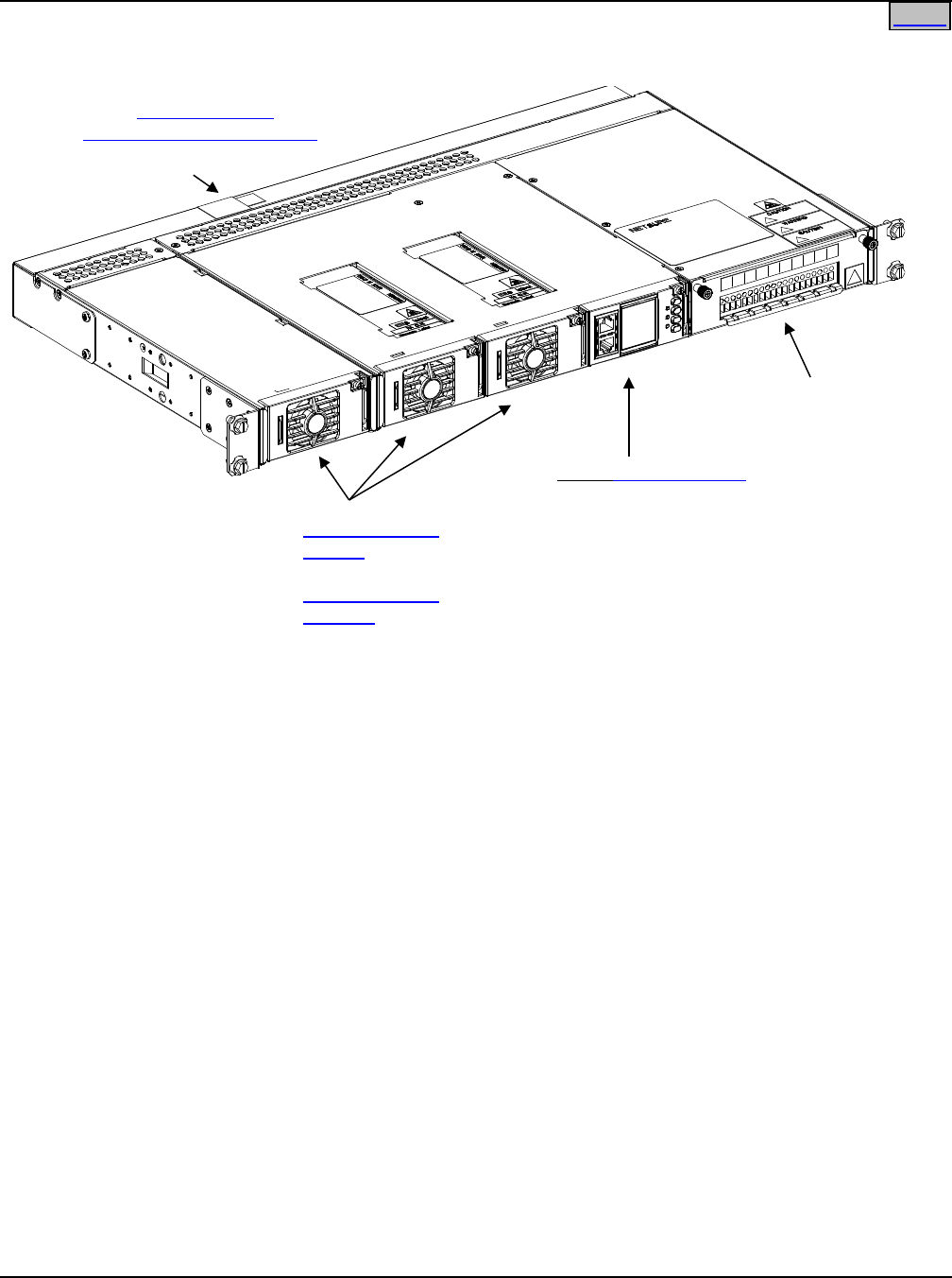
List 1 (List 2 similar)
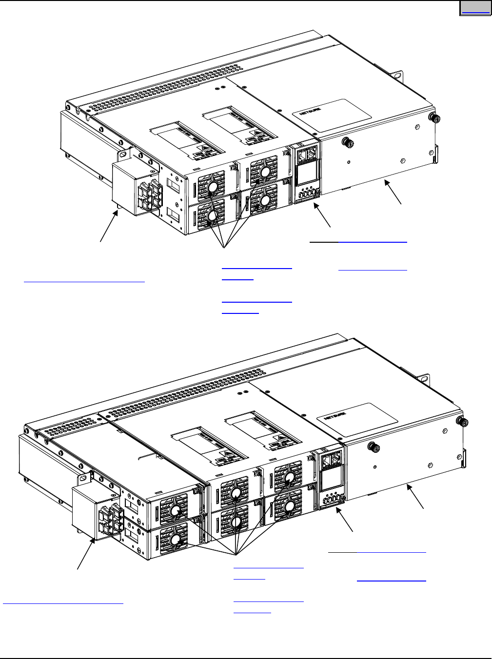
List 5 (List 6 similar)
Home

SAG582136600 System Application Guide
Issue AU, February 21, 2014 Spec. No. 582136600 (Model 211NGFB)
Page 2 of 105
This document is property of Emerson Network Power, Energy Systems, North America, Inc. and contains confidential and proprietary information owned by Emerson Network Power, Energy
Systems, North America, Inc. Any copying, use, or disclosure of it without the written permission of Emerson Network Power, Energy Systems, North America, Inc. is strictly prohibited.
Home
• ACU+ (Advanced Control Unit Plus)
The ACU+ provides Rectifier Module and optional Low Voltage Battery Disconnect
(LVBD) or Low Voltage Load Disconnect (LVLD) control, metering functions,
monitoring functions, and local/remote alarms as well as PCU control, data
acquisition, system alarm management, and advanced battery and energy
management. The ACU+ contains an LCD display and keypad for local access. It
provides connection for binary inputs, programmable relay outputs, and a charge
control function. The controller also supports rectifier temperature compensation if
the system is equipped with a temperature probe (or multiple temperature probes
connected via a Temperature Concentrator (SM TEMP), and ambient temperature
monitoring if equipped with a second temperature probe. The ACU+ provides
Ethernet connection and supports software upgrade via its USB port. It also comes
with a comprehensive web page and SNMP capability for remote system
management.
• SCU+ (Standard Control Unit Plus)
The SCU+ provides Rectifier Module and optional Low Voltage Battery Disconnect
(LVBD) or Low Voltage Load Disconnect (LVLD) control, metering functions,
monitoring functions, and local/remote alarms. The SCU+ contains an LCD display
and keypad for local access. It provides connection for binary inputs, programmable
relay outputs, and a charge control function. The controller also supports rectifier
temperature compensation if the system is equipped with a temperature probe (or
multiple temperature probes connected via a Temperature Concentrator (SM TEMP),
and ambient temperature monitoring if equipped with a second temperature probe.
The SCU+ also provides Ethernet connection and SNMP capability.
• Distribution Unit
Various Distribution Unit options are available, as described in this document. The
Distribution Unit can be equipped with an optional Low Voltage Battery Disconnect
(LVBD) or Low Voltage Load Disconnect (LVLD) contactor.
Family: NetSure™
Spec. No.: 582136600
Model: 211NGFB
Input Voltage Nominal 120/208/240 volts AC, single phase, 3-wire, 50/60 Hz, with an
operating range of 100 to 250 volts. Acceptable input frequency range is
45 to 65 Hz.
Output Voltage: -48 Volts DC
Output Capacity:
Rectifier Module: 500W @ Vout >48Vdc (10.5A @ -48Vdc)
or
1000W @ Vout >48Vdc (20.9A @ -48Vdc)
System Application Guide SAG582136600
Spec. No. 582136600 (Model 211NGFB) Issue AU, February 21, 2014
Page 3 of 105
This document is property of Emerson Network Power, Energy Systems, North America, Inc. and contains confidential and proprietary information owned by Emerson Network Power, Energy
Systems, North America, Inc. Any copying, use, or disclosure of it without the written permission of Emerson Network Power, Energy Systems, North America, Inc. is strictly prohibited.
Home
System: See the following table.
System DC Output Capability
Spec. No.
208/240VAC Input 120VAC Input
+40°C (+104°F) +65°C (+149°F) +40°C (+104°F) +65°C (+149°F)
500W
Rect.
1000W
Rect.
500W
Rect.
1000W
Rect.
500W
Rect.
1000W
Rect.
500W
Rect.
1000W
Rect.
58213660001 20.8A 41.6A 12.6A 25A 20.8A 27.4A 12.6A 16.4A
58213660002 31.2A 62.4A 18.9A 37.5A 31.2A 41.1A 18.9A 24.6A
58213660005 41.6A 83.2A 25.2A 50A 41.6A 54.8A 25.2A 32.8A
58213660006 62.4A 124.8A 37.8A 75A 62.4A 82.2A 37.8A 49.2A
Agency Approval: UL 60950 Recognized, CAN/CSA 22.2
Framework Type: Relay Rack Mounted
Mounting Width: 19” or 23”, nominal
Mounting Depth: 12”
Mounting Height: 1.75” (1RU) or 3.5” (2RU)
Access: Front for Installation, Operation, and Maintenance
Control: Microprocessor
Color: Front Panels are Gray; Shelf is Galvaneal
Environment: -40°C (-40°F) to +65°C (+149°F),
with deratings (see SPECIFICATIONS section)
SAG582136600 System Application Guide
Issue AU, February 21, 2014 Spec. No. 582136600 (Model 211NGFB)
Page 4 of 105
This document is property of Emerson Network Power, Energy Systems, North America, Inc. and contains confidential and proprietary information owned by Emerson Network Power, Energy
Systems, North America, Inc. Any copying, use, or disclosure of it without the written permission of Emerson Network Power, Energy Systems, North America, Inc. is strictly prohibited.
Home
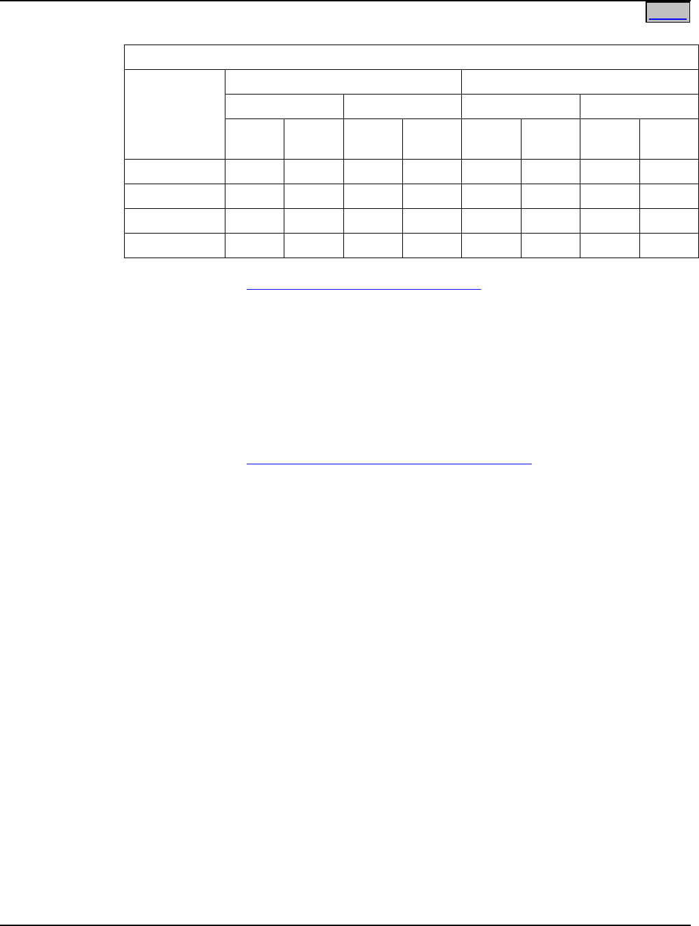
58213660001
58213660002
Distribution Unit
Side AC Input Connectors
(P/O List 1) and
AC Input Cables/Line Cords
Rectifier Module
(500W)
or
Rectifier Module
(1000W)
SCU+ P/N 1M521BNA
Distribution Unit
Side AC Input Connectors
(P/O List 2) and
AC Input Cables/Line Cords
Rectifier Module
(500W)
or
Rectifier Module
(1000W)
SCU+ P/N 1M521BNA
System Application Guide SAG582136600
Spec. No. 582136600 (Model 211NGFB) Issue AU, February 21, 2014
Page 5 of 105
This document is property of Emerson Network Power, Energy Systems, North America, Inc. and contains confidential and proprietary information owned by Emerson Network Power, Energy
Systems, North America, Inc. Any copying, use, or disclosure of it without the written permission of Emerson Network Power, Energy Systems, North America, Inc. is strictly prohibited.
Home
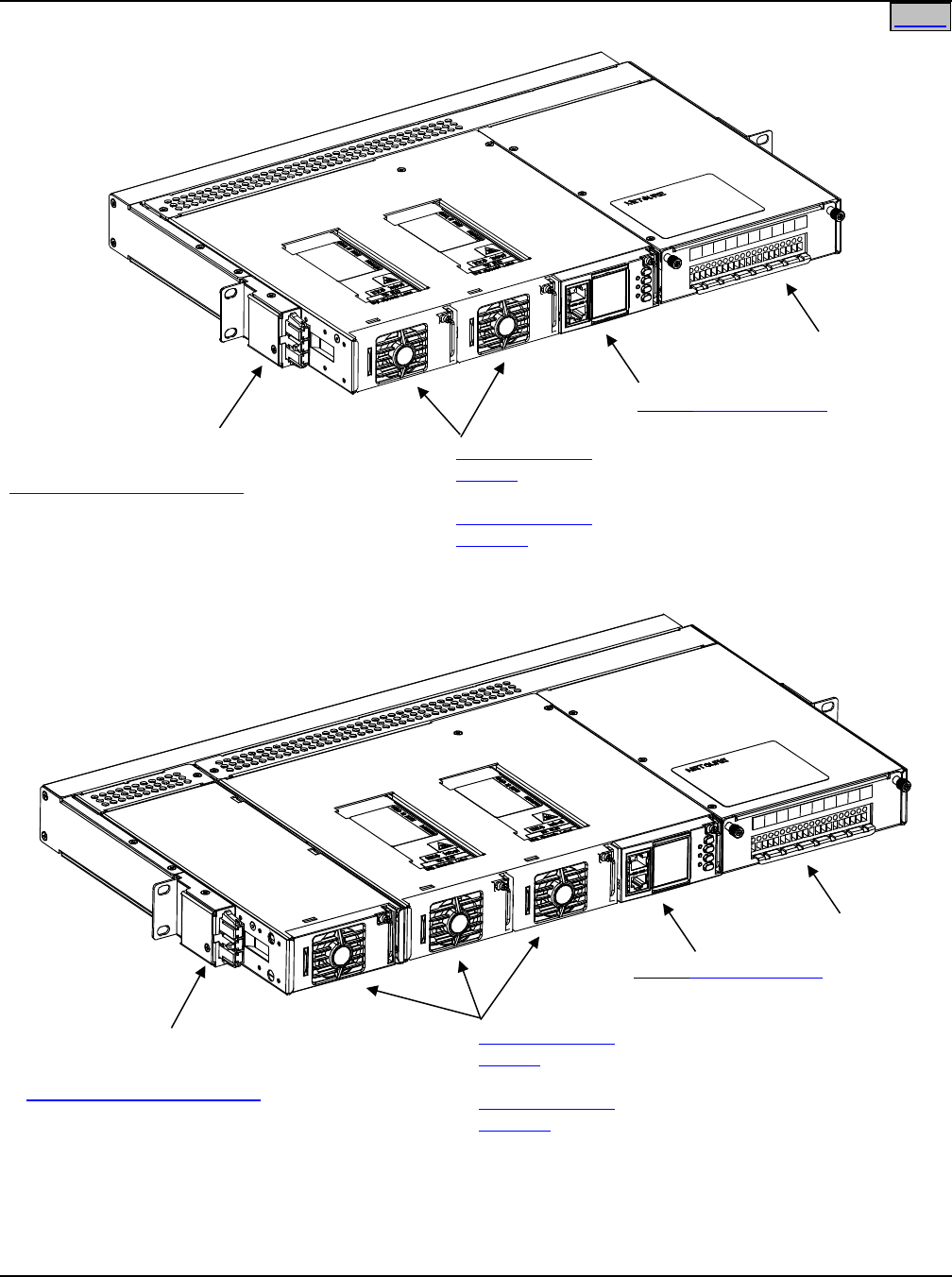
58213660001 with P/N 555260
58213660001 with P/N 556828 Kit
Distribution Unit
Rear AC Input Connector
(P/O P/N 555260) and
AC Input Cables/Line Cords
Rectifier Module
(500W)
or
Rectifier Module
(1000W)
SCU+ P/N 1M521BNA
Distribution Unit
Rear AC Input Connector
(P/O P/N 556828) and
AC Input Cables/Line Cords
Rectifier Module
(500W)
or
Rectifier Module
(1000W)
SCU+ P/N 1M521BNA
SAG582136600 System Application Guide
Issue AU, February 21, 2014 Spec. No. 582136600 (Model 211NGFB)
Page 6 of 105
This document is property of Emerson Network Power, Energy Systems, North America, Inc. and contains confidential and proprietary information owned by Emerson Network Power, Energy
Systems, North America, Inc. Any copying, use, or disclosure of it without the written permission of Emerson Network Power, Energy Systems, North America, Inc. is strictly prohibited.
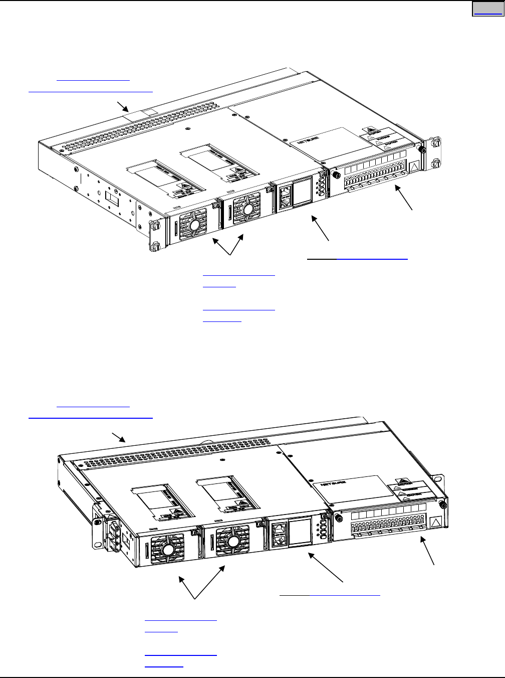
58213660002 with P/N 555261
Distribution Unit
Rear AC Input Connector
(P/O P/N 555261) and
AC Input Cables/Line Cords
Rectifier Module
(500W)
or
Rectifier Module
(1000W)
SCU+ P/N 1M521BNA
Home
System Application Guide SAG582136600
Spec. No. 582136600 (Model 211NGFB) Issue AU, February 21, 2014
Page 7 of 105
This document is property of Emerson Network Power, Energy Systems, North America, Inc. and contains confidential and proprietary information owned by Emerson Network Power, Energy
Systems, North America, Inc. Any copying, use, or disclosure of it without the written permission of Emerson Network Power, Energy Systems, North America, Inc. is strictly prohibited.
Home
Home
58213660005
58213660006
Distribution Unit
Side AC Input Connectors
(P/O List 5) and
AC Input Cables/Line Cords
Rectifier Module
(500W)
or
Rectifier Module
(1000W)
SCU+ P/N 1M521BNA
or
ACU+ P/N 1M820BNA
Distribution Unit
Side AC Input Connectors
(P/O List 6) and
AC Input Cables/Line Cords
Rectifier Module
(500W)
or
Rectifier Module
(1000W)
SCU+ P/N 1M521BNA
or
ACU+ P/N 1M820BNA

SAG582136600 System Application Guide
Issue AU, February 21, 2014 Spec. No. 582136600 (Model 211NGFB)
Page 8 of 105
This document is property of Emerson Network Power, Energy Systems, North America, Inc. and contains confidential and proprietary information owned by Emerson Network Power, Energy
Systems, North America, Inc. Any copying, use, or disclosure of it without the written permission of Emerson Network Power, Energy Systems, North America, Inc. is strictly prohibited.
Home
DISTRIBUTION UNIT (Lists 1 and 2)
List BG: (10) GMT Fuse Load Positions
Low Voltage Battery Disconnect (LVBD)
(1) Set Battery Cables
List NG: (10) GMT Fuse Load Positions
NO Low Voltage Disconnect
(1) Set Battery Cables
DISTRIBUTION UNIT (Lists 5 and 6)
List BF: (13) GMT Fuse Load Positions
Low Voltage Battery Disconnect (LVBD)
(3) Battery Landing Points
List LF: (13) GMT Fuse Load Positions
Low Voltage Load Disconnect (LVLD)
(3) Battery Landing Points
List NF: (13) GMT Fuse Load Positions
NO Low Voltage Disconnect
(3) Battery Landing Points
List BC: (5) GMT Fuse Load Positions
(4) Bullet-Nose Circuit Breaker Load Positions
Low Voltage Battery Disconnect (LVBD)
(3) Battery Landing Points
List LC: (5) GMT Fuse Load Positions
(4) Bullet-Nose Circuit Breaker Load Positions
Low Voltage Load Disconnect (LVLD)
(3) Battery Landing Points
List NC: (5) GMT Fuse Load Positions
(4) Bullet-Nose Circuit Breaker Load Positions
NO Low Voltage Disconnect
(3) Battery Landing Points
List BA: (5) GMT Fuse Load Positions
(2) Bullet-Nose Circuit Breaker Load Positions
(2) Bullet-Nose Circuit Breaker Battery Disconnect Positions
Low Voltage Battery Disconnect (LVBD)
List LA: (5) GMT Fuse Load Positions
(2) Bullet-Nose Circuit Breaker Load Positions
(2) Bullet-Nose Circuit Breaker Battery Disconnect Positions
Low Voltage Load Disconnect (LVLD)
List NA: (5) GMT Fuse Load Positions
(2) Bullet-Nose Circuit Breaker Load Positions
(2) Bullet-Nose Circuit Breaker Battery Disconnect Positions
NO Low Voltage Disconnect

System Application Guide SAG582136600
Spec. No. 582136600 (Model 211NGFB) Issue AU, February 21, 2014
Page 9 of 105
This document is property of Emerson Network Power, Energy Systems, North America, Inc. and contains confidential and proprietary information owned by Emerson Network Power, Energy
Systems, North America, Inc. Any copying, use, or disclosure of it without the written permission of Emerson Network Power, Energy Systems, North America, Inc. is strictly prohibited.
Home
Accessory Options
Relay Racks
Mounting and Adapter Kits
Distribution Devices
AC Input Cables and Line Cords
Ring & Distribution Module
External Battery Disconnect Unit
SM TEMP Temperature Concentrator
Anderson Battery Connector
Digital Input/Relay Output Cables
Replacement Modules
Wiring Notes
Wiring Illustrations
SEE ALSO
System Overview
Table of Contents
List Descriptions
Accessory Descriptions
Specifications
Physical Size Information
Related Documentation
Other List Options
List 60: Five (5) Load Lead Assemblies for 10A GMT Fuse Positions
(for use w/ Lists BC, LC, NC, BA, LA, and NA)
List 61: Eight (8) Load Lead Assemblies for 10A GMT Fuse Positions
(for use w/ Lists BF, LF, and NF)
List 62: Five (5) Load Lead Assemblies for 15A GMT Fuse Positions
(for use w/ Lists BF, LF, and NF)
List 65: Shelf Side Battery Cables
(for use w/ Lists BF, LF, NF, BC, LC, and NC)
List 66: Battery Side Battery Cables
(for use w/ Lists BF, LF, NF, BC, LC, and NC)
List 67: Battery Side Battery Cables
(For use with Lists BC, LC, NC, BF, LF, and NF)
List 71: Optional External Battery Cables (8 AWG) with Anderson Connector
for (1) Battery String (for use w/ Lists BG and NG)
List 72: Optional External Battery Cables with Anderson Connector
for (2) Battery Strings (for use w/ Lists BG and NG)
List 73: Optional External Battery Cables (6 AWG) with Anderson Connector
for (1) Battery String (for use w/ Lists BG and NG)
List 89: Relay Rack Earthquake Anchor Kit
List 90: Temperature Probe (12 ft. total)
List 91: Temperature Probe (33 ft. total)
List 93: Battery Tray (23”)
List 94: Battery Tray (19”)
List KG: GMT Fuse Load Distribution Panel

SAG582136600 System Application Guide
Issue AU, February 21, 2014 Spec. No. 582136600 (Model 211NGFB)
Page 10 of 105
This document is property of Emerson Network Power, Energy Systems, North America, Inc. and contains confidential and proprietary information owned by Emerson Network Power, Energy
Systems, North America, Inc. Any copying, use, or disclosure of it without the written permission of Emerson Network Power, Energy Systems, North America, Inc. is strictly prohibited.
TABLE OF CONTENTS
System
Overview Picture List
Descriptions
Accessory
Descriptions Specifications Physical Size
Information
Related
Documentation
SYSTEM OVERVIEW................................................................................................................................................. 1
58213660001 ......................................................................................................................................................... 4
TABLE OF CONTENTS ........................................................................................................................................... 10
LIST DESCRIPTIONS .............................................................................................................................................. 13
List 1: 1RU High by 19” Wide Shelf............................................................................................................... 13
List 2: 1RU High by 23” Wide Shelf............................................................................................................... 14
List 5: 2RU High by 19” Wide Shelf............................................................................................................... 15
List 6: 2RU High by 23” Wide Shelf............................................................................................................... 16
Rectifier Module (500W), P/N 1R48500 ......................................................................................................... 17
Rectifier Module (1000W), P/N 1R481000 ..................................................................................................... 17
ACU+ (Advanced Control Unit Plus), P/N 1M820BNA .................................................................................. 17
SCU+ (Standard Control Unit Plus), P/N 1M521BNA .................................................................................... 18
List 60: Five (5) Load Lead Assemblies (P/N 535206) for 10A GMT Fuse Positions ................................... 18
List 61: Eight (8) Load Lead Assemblies (P/N 535206) for 10A GMT Fuse Positions ................................. 18
List 62: Five (5) Load Lead Assemblies (P/N 540988) for 15A GMT Fuse Positions ................................... 19
List 65: Shelf Side Battery Cables, P/N 540814 ........................................................................................... 19
List 66: Battery Side Battery Cables, P/N 540954 ........................................................................................ 19
List 67: Battery Cable, P/N 545709 ................................................................................................................ 19
List 71: Optional External Battery Cable Assembly with Anderson Connector for (1) Battery String,
P/N 545493 .................................................................................................................................................... 20
List 72: Optional External Battery Cable Assembly with Anderson Connector for (2) Battery
Strings, P/N 535124 ....................................................................................................................................... 20
List 73: Optional External Battery Cable Assembly with Anderson Connector for (1) Battery String,
P/N 555050 .................................................................................................................................................... 20
List 89: Relay Rack Earthquake Anchor Kit, P/N P0987167 ........................................................................ 21
List 90: Optional Temperature Probe, P/N 04118246 (shelf side half) and P/N 04118247 (probe
side half, 9 ft. long) ......................................................................................................................................... 21
List 91: Optional Temperature Probe, P/N 04118246 (shelf side half) and P/N 04116740 (probe
side half, 30 ft. long) ....................................................................................................................................... 21
List 93: Battery Tray for 23” Relay Rack ....................................................................................................... 22
List 94: Battery Tray for 19” Relay Rack ....................................................................................................... 25
List BF: Distribution Unit with GMT Fuse Load Distribution Positions and with Low Voltage Battery
Disconnect (LVBD) ......................................................................................................................................... 29
List LF: Distribution Unit with GMT Fuse Load Distribution Positions and with Low Voltage Load
Disconnect (LVLD) ......................................................................................................................................... 30
List NF: Distribution Unit with GMT Fuse Load Distribution Positions and w/out Low Voltage
Disconnect ...................................................................................................................................................... 31
List BC: Distribution Unit with GMT Fuse Load Distribution Positions, Circuit Breaker Load
Distribution Positions, and with Low Voltage Battery Disconnect (LVBD) ..................................................... 32
List LC: Distribution Unit with GMT Fuse Load Distribution Positions, Circuit Breaker Load
Distribution Positions, and with Low Voltage Load Disconnect (LVLD) ......................................................... 33
List NC: Distribution Unit with GMT Fuse Load Distribution Positions, Circuit Breaker Load
Distribution Positions, and w/out Low Voltage Disconnect ............................................................................ 34
List BA: Distribution Unit with GMT Fuse Load Distribution Positions, Circuit Breaker Load
Distribution Positions, Circuit Breaker Battery Disconnect Positions, and with Low Voltage Battery
Disconnect (LVBD) ......................................................................................................................................... 35

System Application Guide SAG582136600
Spec. No. 582136600 (Model 211NGFB) Issue AU, February 21, 2014
Page 11 of 105
This document is property of Emerson Network Power, Energy Systems, North America, Inc. and contains confidential and proprietary information owned by Emerson Network Power, Energy
Systems, North America, Inc. Any copying, use, or disclosure of it without the written permission of Emerson Network Power, Energy Systems, North America, Inc. is strictly prohibited.
List LA: Distribution Unit with GMT Fuse Load Distribution Positions, Circuit Breaker Load
Distribution Positions, Circuit Breaker Battery Disconnect Positions, and with Low Voltage Load
Disconnect (LVLD) ......................................................................................................................................... 36
List NA: Distribution Unit with GMT Fuse Load Distribution Positions, Circuit Breaker Load
Distribution Positions, Circuit Breaker Battery Disconnect Positions, and w/out Low Voltage
Disconnect ...................................................................................................................................................... 37
List BG: Distribution Unit with GMT Fuse Load Distribution Positions and with Low Voltage Battery
Disconnect (LVBD) ......................................................................................................................................... 38
List NG: Distribution Unit with GMT Fuse Load Distribution Positions and w/out Low Voltage
Disconnect ...................................................................................................................................................... 39
List KG: Distribution Panel with (20) GMT Fuse Load Distribution Positions ............................................... 40
ACCESSORY DESCRIPTIONS ............................................................................................................................... 41
Relay Racks ....................................................................................................................................................... 41
Mounting and Adapter Kits .............................................................................................................................. 42
Optional Wall Mount Bracket Kit for Lists 1 and 2, P/N 541285 .................................................................... 42
Optional Wall Mount Bracket Kit for Lists 1, 2, 5 and 6, P/N 553203 ............................................................ 42
Optional 19” to 23” 1RU Rack Adapter Kit, P/N 540993 ................................................................................ 42
Optional 19” to 23” 2RU Rack Adapter Kit, P/N 545728 ................................................................................ 42
Optional 19” Rear Cover Kit, P/N 555260 ...................................................................................................... 43
Optional 3” Projection Mount Kit for List 1, P/N 556828 ................................................................................ 43
Optional 23” Rear Cover Kit, P/N 555261 ...................................................................................................... 43
Rear Battery Cable Exit Kit P/N 547645 ........................................................................................................ 43
Distribution Devices .......................................................................................................................................... 44
GMT Load Distribution Fuses ........................................................................................................................ 44
Bullet Nose-Type Circuit Breakers ................................................................................................................. 45
Optional Bullet Nose 6-Position GMT Fuse Module, P/N 545332 ................................................................. 46
Optional Bulk Output Busbar, P/N 535015 .................................................................................................... 46
AC Input Cables and Line Cords ..................................................................................................................... 47
AC Input Cable Assembly, P/N 535232 ......................................................................................................... 47
AC Input Line Cord, 208/240VAC, P/N 540946 ............................................................................................. 47
AC Input Line Cord, 208/240VAC, P/N 545616 ............................................................................................. 48
AC Input Line Cord, 120VAC, P/N 545252 .................................................................................................... 48
AC Input Line Cord, 120VAC, P/N 545478 .................................................................................................... 49
AC Input Line Cord, 120VAC, P/N 545479 .................................................................................................... 49
AC Input Line Cord, 208/240VAC, P/N 545480 ............................................................................................. 50
AC Input Line Cord, 120VAC, P/N 545481 .................................................................................................... 50
AC Input Line Cord, 208/240VAC, P/N 545553 ............................................................................................. 51
AC Input Line Cord, 120VAC, P/N 547525 .................................................................................................... 51
AC Input Line Cord, 120VAC, P/N 548457 .................................................................................................... 52
AC Input Line Cord, 120/208/240VAC, P/N 548196 ...................................................................................... 52
Special Application Digital Input Cable Kit, P/N 554935................................................................................ 53
AP6C57EA/EB Ring & Distribution Module .................................................................................................... 53
External Battery Disconnect Unit, P/N 535282 ............................................................................................... 55
NetSure™ 211BC Battery Cabinet (Spec. No. 541434) ................................................................................... 56
NetSure™ 211BC Battery Cabinet (Spec. No. 545534) ................................................................................... 57
NetSure™ 211BC Battery Cabinet (Spec. No. 545506) ................................................................................... 58
NetSure™ 211BC Battery Cabinet (Spec. No. 554631) ................................................................................... 59
SM TEMP Temperature Concentrator (P/N 547490) ....................................................................................... 60
SM Module RS-485 Interface Cable P/N 547674 ............................................................................................. 60
PCU Blank Filler Panel, P/N PSK4820R-1 ....................................................................................................... 60
Anderson Battery Connector ........................................................................................................................... 61
Digital Input and Relay Output Cables ............................................................................................................ 62
Replacement Modules ...................................................................................................................................... 63
Wiring Notes ...................................................................................................................................................... 64
Shelf Frame Grounding Stud ......................................................................................................................... 64

SAG582136600 System Application Guide
Issue AU, February 21, 2014 Spec. No. 582136600 (Model 211NGFB)
Page 12 of 105
This document is property of Emerson Network Power, Energy Systems, North America, Inc. and contains confidential and proprietary information owned by Emerson Network Power, Energy
Systems, North America, Inc. Any copying, use, or disclosure of it without the written permission of Emerson Network Power, Energy Systems, North America, Inc. is strictly prohibited.
AC Input Branch Circuit Protection and Wiring .............................................................................................. 64
External Alarm and Monitoring Wiring ........................................................................................................... 64
Load Distribution Wiring (GMT Fuses) (Lists BG and NG only) .................................................................... 65
Load Distribution Wiring (GMT Fuses) (Lists BF, LF, and NF only) .............................................................. 65
Load Distribution Wiring (GMT Fuses) (Lists BC, LC, NC, BA, LA, and NA)................................................. 66
Load Distribution Wiring (Optional Bullet-Nose-Type 6-Position GMT Fuse Module) ................................... 66
Load Distribution Wiring (Circuit Breakers) (Lists BC, LC, NC, BA, LA, and NA) .......................................... 66
Load Distribution Wiring (GMT Fuses) (List KG) ........................................................................................... 68
CO Ground Wiring (Lists BF, LF, NF, BC, LC, NC, BA, LA, and NA) ............................................................ 68
Input Battery Wiring (List BG and NG) ........................................................................................................... 68
Input Battery Wiring (to Battery Disconnect Circuit Breakers) (Lists BA, LA, and NA) .................................. 68
Input Battery Wiring (to Battery Busbars) (Lists BF, LF, NF, BC, LC, and NC) ............................................. 69
Wiring Illustrations ............................................................................................................................................ 70
Shelf Frame Grounding Stud (both 1U and 2U Panels, List 1 and 5 shown) ................................................ 70
AC Input Wiring (Lists 1 and 2) ...................................................................................................................... 71
AC Input Wiring (Lists 5 and 6) ...................................................................................................................... 72
External Alarm and Monitoring Wiring (Lists 1 and 2).................................................................................... 73
External Alarm and Monitoring Wiring (Lists 5 and 6).................................................................................... 74
Load Distribution Wiring (GMT Fuses) (Lists BG and NG installed in a List 1 or 2, List 1 shown) ................ 79
Load Distribution Wiring (GMT Fuses) (Lists BF, LF, and NF installed in a List 5 or 6, List 5 shown) .......... 80
Load Distribution Wiring (GMT Fuses) (Lists BC, LC, NC, BA, LA, and NA installed in a List 5 or 6,
List 5 shown) .................................................................................................................................................. 81
Load Distribution Wiring (Optional Bullet Nose 6-Position GMT Fuse Module) ............................................ 82
Load Distribution Wiring (Circuit Breakers) and CO Ground Wiring (Lists BC, LC, and NC installed
in a List 5 or 6, List 5 shown) ......................................................................................................................... 83
Load Distribution Wiring (Circuit Breakers), Input Battery Wiring (Circuit Breakers), and CO Ground
Wiring (Lists BA, LA, and NA installed in a List 5 or 6, List 5 shown) ............................................................ 84
Load Distribution Wiring (GMT Fuses) (List KG) ........................................................................................... 85
Input Battery Wiring (Lists BG and NG installed in a List 1 or 2, List 1 shown) ............................................. 86
Input Battery Wiring (Lists BF, LF, NF, BC, LC, and NC installed in a List 1 or 5, List 5 shown) and
CO Ground Wiring (Lists BF, LF, and NF installed in a List 1 or 5, List 5 shown) ......................................... 87
SPECIFICATIONS .................................................................................................................................................... 88
1. System ........................................................................................................................................................... 88
1.1 Environmental Ratings ............................................................................................................................. 88
1.2 Compliance Information ........................................................................................................................... 88
1.3 Standard Features .................................................................................................................................... 89
PHYSICAL SIZE INFORMATION ............................................................................................................................ 91
Overall Dimensions – List 1 ............................................................................................................................. 91
Additional Dimensions – List 1 with Wall Mounting Kit (P/N 541285) .......................................................... 92
Additional Dimensions – List 1 with Optional 19” Rear Cover Kit, P/N 555260 .......................................... 93
Additional Dimensions – List 1 with Optional 3” Projection Mount Kit, P/N 556828 .................................. 94
Overall Dimensions – List 2 ............................................................................................................................. 95
Additional Dimensions – List 2 with Wall Mounting Kit (P/N 541285) .......................................................... 96
Additional Dimensions – List 2 with Optional 23” Rear Cover Kit, P/N 555261 .......................................... 97
Overall Dimensions – List 5 ............................................................................................................................. 98
Overall Dimensions – List 6 ............................................................................................................................. 99
Additional Dimensions – Lists 1, 2, 5 and 6 with Wall Mounting Kit (P/N 553203) ................................... 100
Overall Dimensions – List KG ........................................................................................................................ 101
Overall Dimensions – 19” Battery Tray ......................................................................................................... 102
Overall Dimensions – 23” Battery Tray ......................................................................................................... 103
BATTERY MANUFACTURER INFORMATION .................................................................................................... 104
RELATED DOCUMENTATION .............................................................................................................................. 104
REVISION RECORD .............................................................................................................................................. 105

System Application Guide SAG582136600
Spec. No. 582136600 (Model 211NGFB) Issue AU, February 21, 2014
Page 13 of 105
This document is property of Emerson Network Power, Energy Systems, North America, Inc. and contains confidential and proprietary information owned by Emerson Network Power, Energy
Systems, North America, Inc. Any copying, use, or disclosure of it without the written permission of Emerson Network Power, Energy Systems, North America, Inc. is strictly prohibited.
Home Home
LIST DESCRIPTIONS
List 1: 1RU High by 19” Wide Shelf
Features
♦ Consists of a 1RU high by 19” wide shelf.
♦ Two (2) 8 AWG 48” long battery cables are factory connected inside the shelf. These cables are
terminated at the customer end in a Red SB50 Anderson battery connector. A mating Anderson battery
connector is provided [Housing: Emerson P/N 138922, Anderson Power Products P/N 992G1. Contacts
(two provided): Emerson P/N 247109602, Anderson Power Products P/N 5952].
♦ Mounted to the side of the shelf is an AC input housing with plug-in connector for a single AC input feed.
♦ The “Digital Input and Relay Outputs Cable” P/N 545494 (shelf side) is factory connected inside the shelf.
A mating half is available.
♦ The shelf houses up to two (2) Rectifier Modules, one (1) Controller, and one (1) Distribution Unit.
Restrictions
Each List 1 shelf holds up to two (2) Rectifier Modules.
Ordering Notes
1) Order List 1 as required.
Also order the following as required.
2) Order one (1) SCU+ controller (P/N 1M521BNA) per shelf. Also specify the appropriate configuration file
for your site.
3) Order up to two (2) Rectifier Modules per shelf: P/N 1R48500 (500W) or P/N 1R481000 (1000W).
4) Order AC Input Cables or Line Cords as required. Note that each List 1 shelf requires one (1) AC Input
Cable or Line Cord.
5) Order one (1) Distribution Unit (List BG or NG) per shelf.
6) Order Optional External Battery Cables with Anderson Connector for one (1) to two (2) Battery Strings per
List 71, 72 or 73.
7) Order Relay Rack Anchor Kit(s) (List 89) as required.
8) Order up to two (2) Temperature Probes (List 90 or 91) as required. One probe is used with the Battery
Charge Temperature Compensation feature, the other to monitor ambient temperature.
9) Order Battery Trays (List 94) as required.
10) Order Relay Racks per ACCESSORY DESCRIPTIONS section.
11) Order Distribution Devices per ACCESSORY DESCRIPTIONS section.
12) Order External Battery Disconnect Unit per ACCESSORY DESCRIPTIONS section.
13) Order Battery Cabinet per ACCESSORY DESCRIPTIONS section.
14) Order Mating Digital Input/Relay Output Cables per ACCESSORY DESCRIPTIONS section.
15) Order Spare Anderson Battery Connector per ACCESSORY DESCRIPTIONS section.
16) Order Special Application Digital Input Cable Kit per ACCESSORY DESCRIPTIONS section.

SAG582136600 System Application Guide
Issue AU, February 21, 2014 Spec. No. 582136600 (Model 211NGFB)
Page 14 of 105
This document is property of Emerson Network Power, Energy Systems, North America, Inc. and contains confidential and proprietary information owned by Emerson Network Power, Energy
Systems, North America, Inc. Any copying, use, or disclosure of it without the written permission of Emerson Network Power, Energy Systems, North America, Inc. is strictly prohibited.
Home
List 2: 1RU High by 23” Wide Shelf
Features
♦ Consists of a 1RU high by 23” wide shelf.
♦ Two (2) 8 AWG 48” long battery cables are factory connected inside the shelf. These cables are
terminated at the customer end in a Red SB50 Anderson battery connector. A mating Anderson battery
connector is provided [Housing: Emerson P/N 138922, Anderson Power Products P/N 992G1. Contacts
(two provided): Emerson P/N 247109602, Anderson Power Products P/N 5952].
♦ Mounted to the side of the shelf is an AC input housing with plug-in connector for a single AC input feed.
♦ The “Digital Input and Relay Outputs Cable” P/N 545494 (shelf side) is factory connected inside the shelf.
A mating half is available.
♦ The shelf houses up to three (3) Rectifier Modules, one (1) Controller, and one (1) Distribution Unit.
Restrictions
Each List 2 shelf holds up to three (3) Rectifier Modules.
Ordering Notes
1) Order List 2 as required.
Also order the following as required.
2) Order one (1) SCU+ controller (P/N 1M521BNA) per shelf. Also specify the appropriate configuration file
for your site.
3) Order up to three (3) Rectifier Modules per shelf: P/N 1R48500 (500W) or P/N 1R481000 (1000W).
4) Order AC Input Cables or Line Cords as required. Note that each List 2 shelf requires one (1) AC Input
Cable or Line Cord.
5) Order one (1) Distribution Unit (List BG or NG) per shelf.
6) Order Optional External Battery Cables with Anderson Connector for one (1) to two (2) Battery Strings per
List 71, 72 or 73.
7) Order Relay Rack Anchor Kit(s) (List 89) as required.
8) Order up to two (2) Temperature Probes (List 90 or 91) as required. One probe is used with the Battery
Charge Temperature Compensation feature, the other to monitor ambient temperature.
9) Order Battery Trays (List 93) as required.
10) Order Relay Racks per ACCESSORY DESCRIPTIONS section.
11) Order Distribution Devices per ACCESSORY DESCRIPTIONS section.
12) Order External Battery Disconnect Unit per ACCESSORY DESCRIPTIONS section.
13) Order Battery Cabinet per ACCESSORY DESCRIPTIONS section.
14) Order Mating Digital Input/Relay Output Cables per ACCESSORY DESCRIPTIONS section.
15) Order Spare Anderson Battery Connector per ACCESSORY DESCRIPTIONS section.
16) Order Special Application Digital Input Cable Kit per ACCESSORY DESCRIPTIONS section.

System Application Guide SAG582136600
Spec. No. 582136600 (Model 211NGFB) Issue AU, February 21, 2014
Page 15 of 105
This document is property of Emerson Network Power, Energy Systems, North America, Inc. and contains confidential and proprietary information owned by Emerson Network Power, Energy
Systems, North America, Inc. Any copying, use, or disclosure of it without the written permission of Emerson Network Power, Energy Systems, North America, Inc. is strictly prohibited.
Home
List 5: 2RU High by 19” Wide Shelf
Features
♦ Consists of a 2RU high by 19” wide shelf.
♦ Mounted to the side of the shelf is an AC input housing with plug-in connectors for two (2) AC input feeds.
♦ Includes the Customer Interface Board that provides additional Relay Outputs and Digital Inputs.
♦ The “Relay Outputs Cable” P/N 541308 (shelf side) is factory connected inside the shelf. A mating half is
available. A “Digital Input Cable” (shelf side and customer side) is also available.
♦ The shelf houses up to four (4) Rectifier Modules, one (1) Controller, and one (1) Distribution Unit.
Restrictions
Each List 5 shelf holds up to four (4) Rectifier Modules.
Ordering Notes
1) Order List 5 as required.
Also order the following as required.
2) Order one (1) SCU+ controller (P/N 1M521BNA) or (1) ACU+ controller (P/N 1M820BNA) per shelf. Also
specify the appropriate configuration file for your site.
3) Order up to four (4) Rectifier Modules per shelf: P/N 1R48500 (500W) or P/N 1R481000 (1000W).
4) Order AC Input Cables or Line Cords as required. Note that each List 5 shelf requires two (2) AC Input
Cables or Line Cords.
5) Order one (1) Distribution Unit (List BF, LF, NF, BC, LC, NC, BA, LA, or NA) per shelf.
6) Order one (1) List 60 for each List BC, LC, NC, BA, LA, or NA ordered.
Each List 60 provides five (5) Load Lead Assemblies for 10A GMT Fuse Positions.
Order one (1) List 61 for each List BF, LF, or NF ordered.
Each List 61 provides eight (8) Load Lead Assemblies for 10A GMT Fuse Positions.
Order one (1) List 62 for each List BF, LF, or NF ordered.
Each List 62 provides five (5) Load Lead Assemblies for 15A GMT Fuse Positions.
7) Order one (1) List KG Distribution Fuse Panel per shelf, as required.
8) Order three (3) sets of Shelf Side and three (3) sets of Battery Side Battery Cables (List 65 and List 66)
for each List BC, LC, NC, BF, LF, or NF ordered.
9) Order up to three (3) List 67 for each List BC, LC, NC, BF, LF, and NF ordered.
10) Order Relay Rack Anchor Kit(s) (List 89) as required.
11) Order up to two (2) Temperature Probes (List 90 or 91) as required. One probe is used with the Battery
Charge Temperature Compensation feature, the other to monitor ambient temperature.
12) Order Battery Trays (List 94) as required.
13) Order Relay Racks per ACCESSORY DESCRIPTIONS section.
14) Order Distribution Devices per ACCESSORY DESCRIPTIONS section.
15) Order External Battery Disconnect Unit per ACCESSORY DESCRIPTIONS section.
16) Order Battery Cabinet per ACCESSORY DESCRIPTIONS section.
17) Order Digital Input/Relay Output Cables per ACCESSORY DESCRIPTIONS section.
18) Order lugs per Wiring Notes under ACCESSORY DESCRIPTIONS section.

SAG582136600 System Application Guide
Issue AU, February 21, 2014 Spec. No. 582136600 (Model 211NGFB)
Page 16 of 105
This document is property of Emerson Network Power, Energy Systems, North America, Inc. and contains confidential and proprietary information owned by Emerson Network Power, Energy
Systems, North America, Inc. Any copying, use, or disclosure of it without the written permission of Emerson Network Power, Energy Systems, North America, Inc. is strictly prohibited.
Home
List 6: 2RU High by 23” Wide Shelf
Features
♦ Consists of a 2RU high by 23” wide shelf.
♦ Mounted to the side of the shelf is an AC input housing with plug-in connectors for two (2) AC input feeds.
♦ Includes the Customer Interface Board that provides additional Relay Outputs and Digital Inputs.
♦ The “Relay Outputs Cable” P/N 541308 (shelf side) is factory connected inside the shelf. A mating half is
available. A “Digital Input Cable” (shelf side and customer side) is also available.
♦ The shelf houses up to six (6) Rectifier Modules, one (1) Controller, and one (1) Distribution Unit.
Restrictions
Each List 6 shelf holds up to six (6) Rectifier Modules.
Ordering Notes
1) Order List 6 as required.
Also order the following as required.
2) Order one (1) SCU+ controller (P/N 1M521BNA) or (1) ACU+ controller (P/N 1M820BNA) per shelf. Also
specify the appropriate configuration file for your site.
3) Order up to six (6) Rectifier Modules per shelf: P/N 1R48500 (500W) or P/N 1R481000 (1000W).
4) Order AC Input Cables or Line Cords as required. Note that each List 6 shelf requires two (2) AC Input
Cables or Line Cords.
5) Order one (1) Distribution Unit (List BF, LF, NF, BC, LC, NC, BA, LA, or NA) per shelf.
6) Order one (1) List 60 for each List BC, LC, NC, BA, LA, or NA ordered.
Each List 60 provides five (5) Load Lead Assemblies for 10A GMT Fuse Positions.
Order one (1) List 61 for each List BF, LF, or NF ordered.
Each List 61 provides eight (8) Load Lead Assemblies for 10A GMT Fuse Positions.
Order one (1) List 62 for each List BF, LF, or NF ordered.
Each List 62 provides five (5) Load Lead Assemblies for 15A GMT Fuse Positions.
7) Order one (1) List KG GMT Distribution Fuse Panel per shelf, as required.
8) Order three (3) sets of Shelf Side and three (3) sets of Battery Side Battery Cables (List 65 and List 66)
for each List BC, LC, NC, BF, LF, or NF ordered.
9) Order up to three (3) List 67 for each List BC, LC, NC, BF, LF, and NF ordered.
10) Order Relay Rack Anchor Kit(s) (List 89) as required.
11) Order up to two (2) Temperature Probes (List 90 or 91) as required. One probe is used with the Battery
Charge Temperature Compensation feature, the other to monitor ambient temperature.
12) Order Battery Trays (List 93) as required.
13) Order Relay Racks per ACCESSORY DESCRIPTIONS section.
14) Order Distribution Devices per ACCESSORY DESCRIPTIONS section.
15) Order External Battery Disconnect Unit per ACCESSORY DESCRIPTIONS section.
16) Order Battery Cabinet per ACCESSORY DESCRIPTIONS section.
17) Order Digital Input/Relay Output Cables per ACCESSORY DESCRIPTIONS section.
18) Order lugs per Wiring Notes under ACCESSORY DESCRIPTIONS section.
System Application Guide SAG582136600
Spec. No. 582136600 (Model 211NGFB) Issue AU, February 21, 2014
Page 17 of 105
This document is property of Emerson Network Power, Energy Systems, North America, Inc. and contains confidential and proprietary information owned by Emerson Network Power, Energy
Systems, North America, Inc. Any copying, use, or disclosure of it without the written permission of Emerson Network Power, Energy Systems, North America, Inc. is strictly prohibited.
Home
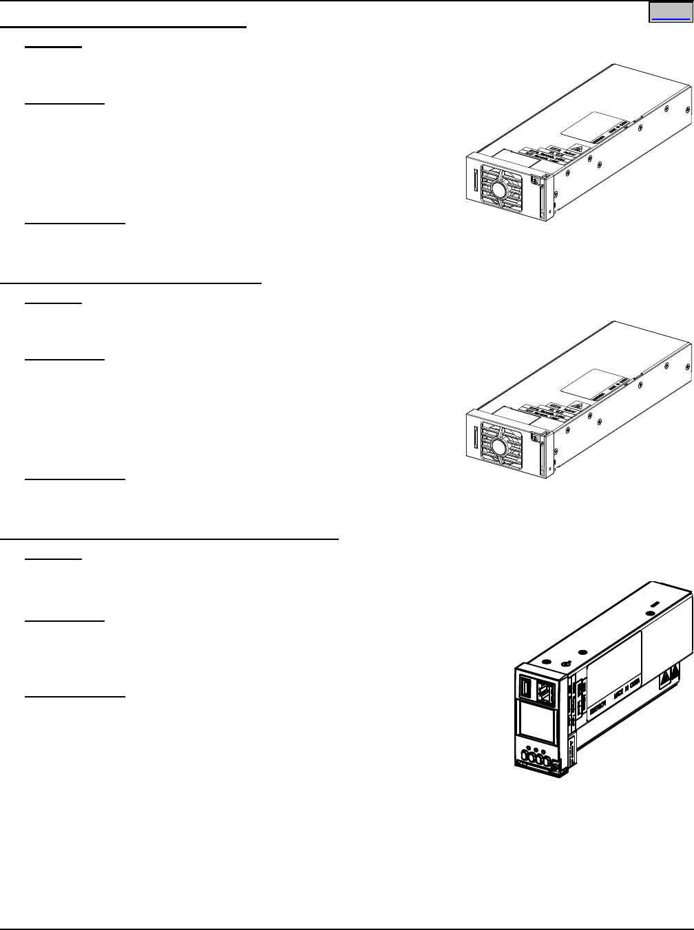
Rectifier Module (500W), P/N 1R48500
Features
♦ Provides one (1) Model R48-500, Spec. No. 1R48500,
500 watt / 48 volt Rectifier Module.
Restrictions
Each List 1 Shelf holds up to two (2) Rectifier Modules.
Each List 2 Shelf holds up to three (3) Rectifier Modules.
Each List 5 Shelf holds up to four (4) Rectifier Modules.
Each List 6 Shelf holds up to six (6) Rectifier Modules.
DO NOT install different wattage Rectifier Modules in same shelf.
Ordering Notes
1) Order by P/N (1R48500) as required.
Rectifier Module (1000W), P/N 1R481000
Features
♦ Provides one (1) Model R48-1000, Spec. No. 1R481000,
1000 watt / 48 volt Rectifier Module.
Restrictions
Each List 1 Shelf holds up to two (2) Rectifier Modules.
Each List 2 Shelf holds up to three (3) Rectifier Modules.
Each List 5 Shelf holds up to four (4) Rectifier Modules.
Each List 6 Shelf holds up to six (6) Rectifier Modules.
DO NOT install different wattage Rectifier Modules in same shelf.
Ordering Notes
1) Order by P/N (1R481000) as required.
ACU+ (Advanced Control Unit Plus), P/N 1M820BNA
Features
♦ Provides the ACU+ Controller.
♦ Factory programmed with the configuration file specified when ordered.
Restrictions
ACU+ is not available in List 1 or List 2 shelves.
Each List 5 or List 6 shelf must contain one (1) SCU+ or one (1) ACU+
Controller.
Ordering Notes
1) Order one (1) ACU+ (P/N 1M820BNA) or one (1) SCU+ Controller (P/N
1M521BNA) or for each shelf.
For the ACU+ controller, specify also one of the following configurations.
a) List 5 and 6 with Low Voltage Disconnect: 550166.
b) List 5 and 6 without Low Voltage Disconnect: 550167.
Note: For custom ACU+ configurations, contact Emerson.
SAG582136600 System Application Guide
Issue AU, February 21, 2014 Spec. No. 582136600 (Model 211NGFB)
Page 18 of 105
This document is property of Emerson Network Power, Energy Systems, North America, Inc. and contains confidential and proprietary information owned by Emerson Network Power, Energy
Systems, North America, Inc. Any copying, use, or disclosure of it without the written permission of Emerson Network Power, Energy Systems, North America, Inc. is strictly prohibited.
Home
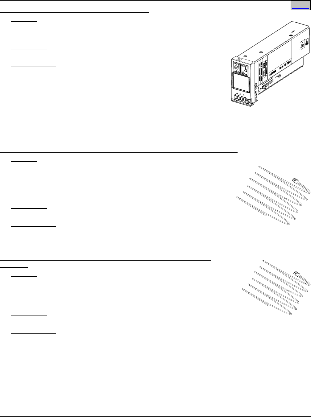
SCU+ (Standard Control Unit Plus), P/N 1M521BNA
Features
♦ Provides the SCU+ Controller.
♦ Factory programmed with the configuration file specified when ordered.
Restrictions
Each shelf must contain one (1) SCU+ or one (1) ACU+ Controller.
Ordering Notes
1) Order one (1) SCU+ Controller (P/N 1M521BNA) or one (1) ACU+ (P/N
1M820BNA) for each shelf.
For the SCU+ controller, specify also one of the following configurations.
a) List 1 and 2 with Low Voltage Disconnect: 545304.
b) List 1 and 2 without Low Voltage Disconnect: 545305.
c) List 5 and 6 with Low Voltage Disconnect: 545298.
d) List 5 and 6 without Low Voltage Disconnect: 545299.
Note: For custom SCU+ configurations, contact Emerson.
List 60: Five (5) Load Lead Assemblies (P/N 535206) for 10A GMT Fuse Positions
Features
♦ Provides 12’ long, 16 AWG, load and load return leads that are terminated
on one end with the appropriate mating connector to plug into the system’s
10A GMT fuse connector on a List BC, LC, NC, BA, LA, or NA Distribution
Unit, and are left un-terminated at the remaining end for connection into
customer loads.
Restrictions
For use with List BC, LC, NC, BA, LA, and NA Distribution units only.
Ordering Notes
1) Order one (1) List 60 for each List BC, LC, NC, BA, LA, or NA Distribution Unit.
Each List 60 provides five (5) GMT fuse load lead assemblies, P/N 535206.
List 61: Eight (8) Load Lead Assemblies (P/N 535206) for 10A GMT Fuse
Positions
Features
♦ Provides 12’ long, 16 AWG, load and load return leads that are terminated on
one end with the appropriate mating connector to plug into the system’s 10A
GMT fuse connector on a List BF, LF, or NF Distribution Unit, and are left un-
terminated at the remaining end for connection into customer loads.
Restrictions
For use with List BF, LF, and NF Distribution units only.
Ordering Notes
1) Order one (1) List 61 for each List BF, LF, or NF Distribution Unit.
Each List 61 provides eight (8) GMT fuse load lead assemblies, P/N 535206.
System Application Guide SAG582136600
Spec. No. 582136600 (Model 211NGFB) Issue AU, February 21, 2014
Page 19 of 105
This document is property of Emerson Network Power, Energy Systems, North America, Inc. and contains confidential and proprietary information owned by Emerson Network Power, Energy
Systems, North America, Inc. Any copying, use, or disclosure of it without the written permission of Emerson Network Power, Energy Systems, North America, Inc. is strictly prohibited.
Home
List 62: Five (5) Load Lead Assemblies (P/N 540988) for 15A GMT Fuse Positions
Features
♦ Provides 12’ long, 14 AWG, load and load return leads that are terminated on one end with the
appropriate mating connector to plug into the system’s 15A GMT fuse connector
on a List BF, LF, or NF Distribution Unit, and are left un-terminated at the
remaining end for connection into customer loads.
Restrictions
For use with List BF, LF, and NF Distribution units only.
Ordering Notes
1) Order one (1) List 62 for each List BF, LF, or NF Distribution Unit.
Each List 62 provides five (5) GMT fuse load lead assemblies, P/N 540988.
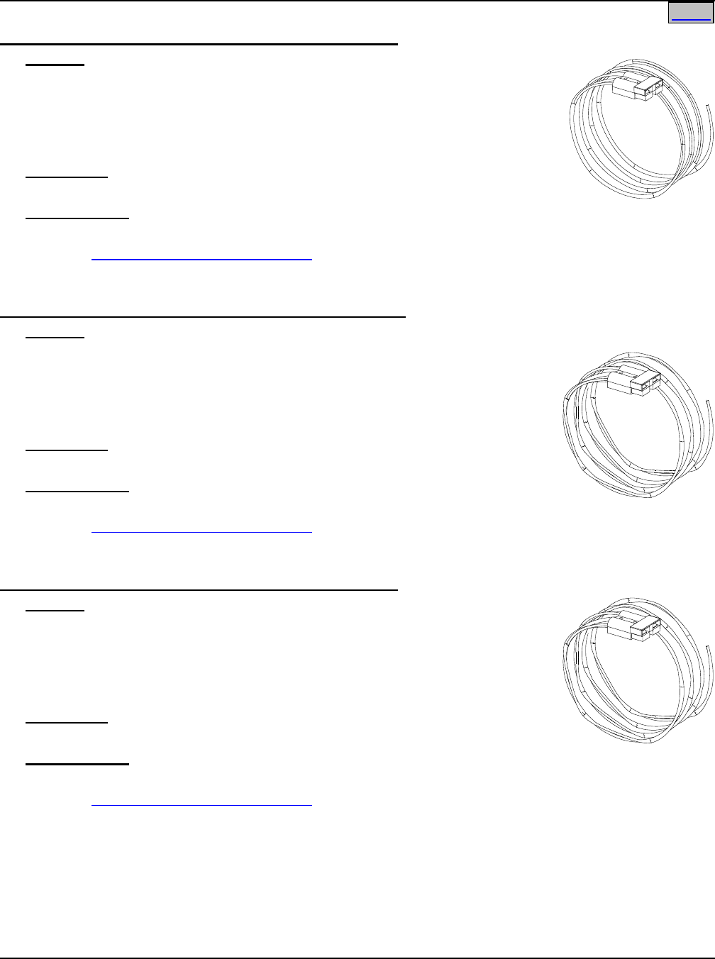
List 65: Shelf Side Battery Cables, P/N 540814
Features
♦ Provides two (2) 3’ long, 2 AWG, battery cables terminated in a 2-position Red
SB120 Anderson connector (mates with the Anderson connector on List 66).
Remaining end terminated in lugs for connection to shelf.
Restrictions
For use with List BF, LF, NF, BC, LC, and NC Distribution units only.
Ordering Notes
1) Order as required. Each shelf provides landings for up to three (3) battery strings.
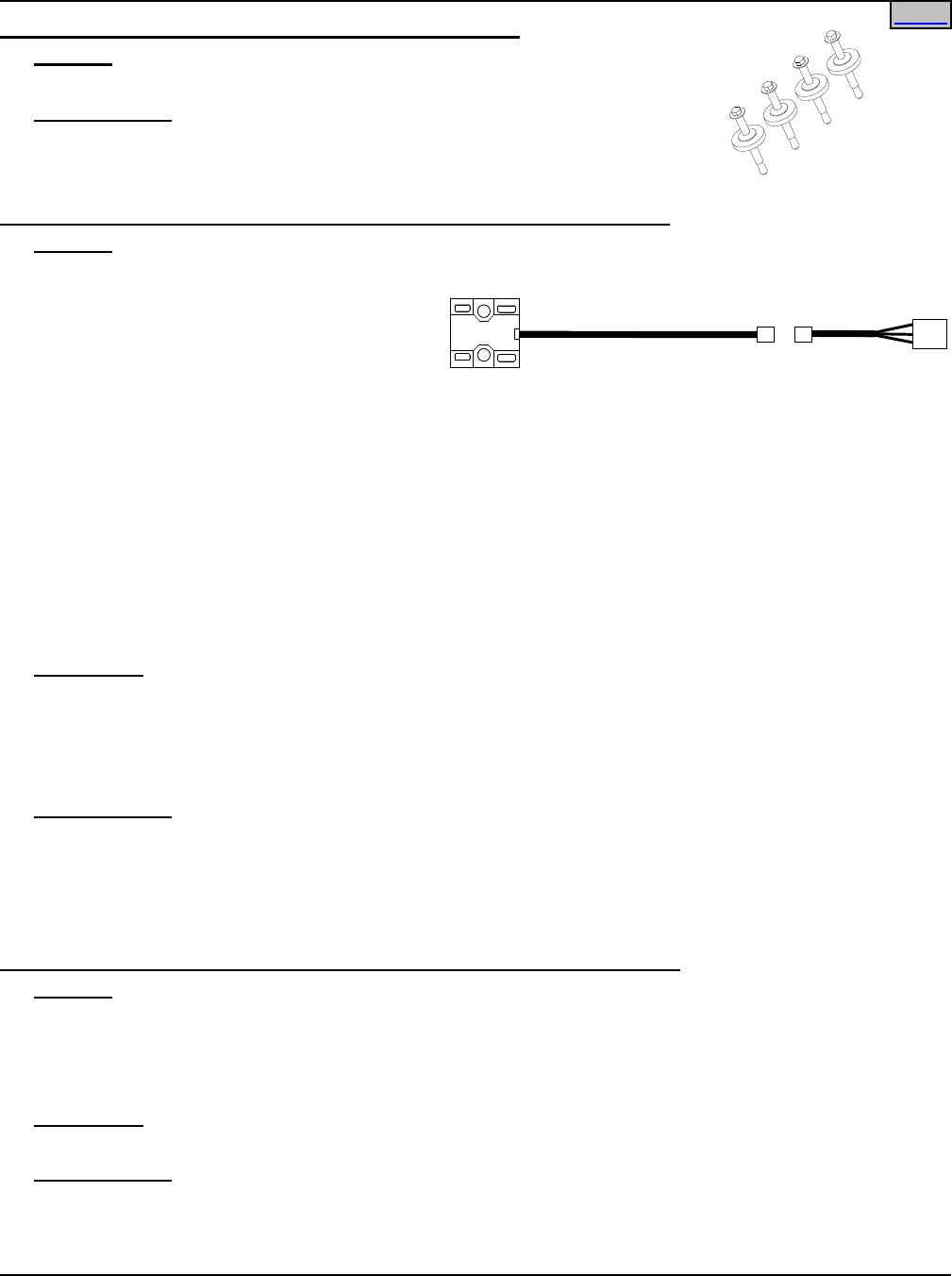
List 66: Battery Side Battery Cables, P/N 540954
Features
♦ Provides two (2) 12’ long, 2 AWG, battery cables terminated in a 2-position Red SB120 Anderson
connector (mates with the Anderson connector on List 65). Remaining end un-
terminated for connection to batteries.
Restrictions
For use with List BF, LF, NF, BC, LC, and NC only.
Ordering Notes
1) Order as required. Each shelf provides landings for up to three (3) battery
strings.
List 67: Battery Cable, P/N 545709
Features
♦ Provides two (2) 4’ long, 8 AWG, battery cables terminated in a 2-position Anderson
connector on the battery side. Remaining end terminated in lugs for connection to shelf.
Restrictions
For use with P/N 541434, P/N 545534, P/N 545506, or P/N 554631 battery cabinets only.
For use with List BF, LF, NF, BC, LC, and NC Distribution units only.
Ordering Notes
1) Order up to three (3) List 67 for each List BC, LC, NC, BF, LF, and NF ordered.
2) Order one (1) for each battery cabinet feed required.
SAG582136600 System Application Guide
Issue AU, February 21, 2014 Spec. No. 582136600 (Model 211NGFB)
Page 20 of 105
This document is property of Emerson Network Power, Energy Systems, North America, Inc. and contains confidential and proprietary information owned by Emerson Network Power, Energy
Systems, North America, Inc. Any copying, use, or disclosure of it without the written permission of Emerson Network Power, Energy Systems, North America, Inc. is strictly prohibited.
Home
List 71: Optional External Battery Cable Assembly
with Anderson Connector for (1) Battery String, P/N 545493
Features
♦ Provides two (2) 6’ long, 8 AWG, battery cables terminated in a Red SB50
Anderson connector for connecting one (1) battery string to the system.
♦ One end of the assembly connects to the Anderson connector factory wired to
the shelf’s battery connection points, and the other end contains two (2) un-
terminated cables for connection into a customer battery string.
Restrictions
For use with List BG and NG only.
Ordering Notes
1) Order if required.
2) Order Spare Anderson Battery Connector per ACCESSORY DESCRIPTIONS section.
List 72: Optional External Battery Cable Assembly
with Anderson Connector for (2) Battery Strings, P/N 535124
Features
♦ Provides four (4) 6’ long, 10 AWG, battery cables terminated in a Red SB50
Anderson connector for connecting two (2) battery strings to the system.
♦ One end of the assembly connects to the Anderson connector factory wired to
the shelf’s battery connection points, and the other end contains four (4) un-
terminated cables for connection into customer battery strings.
Restrictions
For use with List BG and NG Distribution units only.
Ordering Notes
1) Order if required.
2) Order Spare Anderson Battery Connector per ACCESSORY DESCRIPTIONS section.
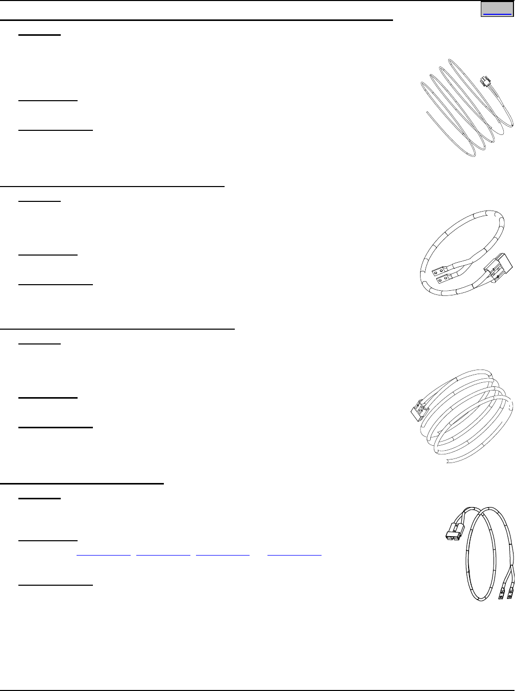
List 73: Optional External Battery Cable Assembly
with Anderson Connector for (1) Battery String, P/N 555050
Features
♦ Provides two (2) 6’ long, 6 AWG, battery cables terminated in a Red SB50
Anderson connector for connecting one (1) battery string to the system.
♦ One end of the assembly connects to the Anderson connector factory wired to
the shelf’s battery connection points, and the other end contains two (2) un-
terminated cables for connection into a customer battery string.
Restrictions
For use with List BG and NG only.
Ordering Notes
1) Order if required.
2) Order Spare Anderson Battery Connector per ACCESSORY DESCRIPTIONS section.
System Application Guide SAG582136600
Spec. No. 582136600 (Model 211NGFB) Issue AU, February 21, 2014
Page 21 of 105
This document is property of Emerson Network Power, Energy Systems, North America, Inc. and contains confidential and proprietary information owned by Emerson Network Power, Energy
Systems, North America, Inc. Any copying, use, or disclosure of it without the written permission of Emerson Network Power, Energy Systems, North America, Inc. is strictly prohibited.
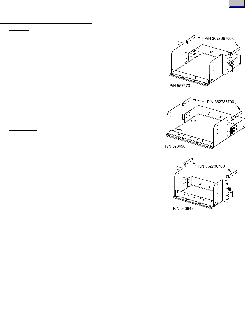
List 89: Relay Rack Earthquake Anchor Kit, P/N P0987167
Features
♦ Provides four (4) sets of hardware for anchoring the relay rack to the floor.
Ordering Notes
1) Order as required.
List 90: Optional Temperature Probe,
P/N 04118246 (shelf side half) and P/N 04118247 (probe side half, 9 ft. long)
Features
♦ Up to two (2) temperature probes can be connected to the Customer Interface (IB2) Board. Either or both
probes can be programmed to monitor
ambient temperature or battery
temperature.
♦ A temperature probe set as a battery
probe can also be designated to be used for the battery charge temperature compensation feature. If the
system is equipped with the ACU+ Controller, the battery charge temperature compensation feature can
be programmed to use one probe or the average or highest value of all probes programmed to monitor
battery temperature. The battery charge temperature compensation feature allows the controller to
automatically increase or decrease the output voltage of the system to maintain battery float current as
battery temperature decreases or increases, respectively. Battery life can be extended when an optimum
charge voltage to the battery with respect to temperature is maintained.
♦ If the system is equipped with the ACU+ Controller, a temperature probe set as a battery probe can also
be used for controlling against battery thermal runaway (BTRM feature).
♦ The Temperature Probe assembly consists of two pieces that plug together to make a complete probe.
When ordered, P/N 04118246 (3 feet long) is pre-wired to the shelf and P/N 04118247 (9 feet long) is
shipped loose. Total length: 12 ft.
Restrictions
A temperature probe programmed to monitor battery temperature should be mounted on the top or side of a
battery cell to sense battery temperature. A temperature probe used for battery charge temperature
compensation or BTRM (Battery Thermal Runaway Management) should also be mounted on the top or side
of a battery cell. A temperature probe programmed to monitor ambient temperature should be mounted in a
convenient location, away from direct sources of heat or cold.
Ordering Notes
1) Order up to two (2) Temperature Probes for each shelf, as required.
Each List 90 includes one (1) P/N 04118246 and one (1) P/N 04118247.
2) For a Temperature Probe with a longer cable see List 91.
List 91: Optional Temperature Probe,
P/N 04118246 (shelf side half) and P/N 04116740 (probe side half, 30 ft. long)
Features
♦ See above for description of Temperature Probes.
♦ The Temperature Probe assembly consists of two pieces that plug together to make a complete probe.
When ordered, P/N 04118246 (3 feet long) is pre-wired to the shelf and P/N 04116740 (30 feet long) is
shipped loose. Total Length: 33 ft.
Restrictions
See above for restrictions.
Ordering Notes
1) Order up to two (2) Temperature Probes for each shelf, as required.
Each List 91 includes one (1) P/N 04118246 and one (1) P/N 04116740.
Home
SAG582136600 System Application Guide
Issue AU, February 21, 2014 Spec. No. 582136600 (Model 211NGFB)
Page 22 of 105
This document is property of Emerson Network Power, Energy Systems, North America, Inc. and contains confidential and proprietary information owned by Emerson Network Power, Energy
Systems, North America, Inc. Any copying, use, or disclosure of it without the written permission of Emerson Network Power, Energy Systems, North America, Inc. is strictly prohibited.
2) For a Temperature Probe with a shorter cable see List 90.
List 93: Battery Tray for 23” Relay Rack
Features
♦ Provides one battery tray that mounts four (4) 12V front terminal
Valve Regulated Lead Acid (VRLA) batteries. Batteries are
configured as one (1) 48V string.
♦ Accepts various VRLA batteries. See Ordering Notes below.
♦ See Overall Dimensions - 23” Battery Tray under PHYSICAL SIZE
INFORMATION for battery tray dimensions and typical
arrangement. Note that two battery trays are available to
accommodate the various size batteries listed in the Ordering
Notes tables.
♦ Trays can be ordered with or without battery disconnect circuit
breakers. When circuit breakers are ordered, one is provided in
the -48V lead of each battery string (1 circuit breaker per tray).
♦ Battery cables are available terminated at the power system end
in an Anderson connector. Battery lugs are available for the
remaining end.
Restrictions
For 23” relay racks only.
Maximum number of List 93’s per rack is three (3).
A single List 93 must mount at bottom of rack. Multiple List 93’s must
mount starting at bottom of rack and working upward.
Ordering Notes
1) Order multiples of List 93 for more than one (1) battery tray. See
Restrictions above.
2) Order one (1) or more P/N 362736700 Cable Bracket(s) as
required.
3) Order batteries separately. Tables A, B, and C list the batteries
recommended for use with List 93.
4) Specify rack spacing of 6U (10.5”), 7U (12.25”), or 8U (14”)
between trays and above top tray as required for battery
clearance. See Tables A, B, and C.
5) Battery lugs are provided, as specified from Table D.
6) Specify with or without battery disconnect circuit breakers.
Note: All List 93 trays in a rack will be furnished with or without battery disconnect circuit breakers as
specified for the first tray ordered.
7) If ordering List 93 with circuit breakers, order one (1) circuit breaker per List 93 from Table E.
8) If ordering List 93 with circuit breakers, specify breaker mounting on left side of tray, right side of tray, or
remote mounting. Circuit breaker mounting kits shown in the Table E will be installed. Kit numbers are
provided for reference only
9) If ordering List 93 with circuit breakers, order Alarm Jumper P/N 524384 for each system to connect the
alarm terminal of up to three (3) battery disconnect circuit breakers.
Home
System Application Guide SAG582136600
Spec. No. 582136600 (Model 211NGFB) Issue AU, February 21, 2014
Page 23 of 105
This document is property of Emerson Network Power, Energy Systems, North America, Inc. and contains confidential and proprietary information owned by Emerson Network Power, Energy
Systems, North America, Inc. Any copying, use, or disclosure of it without the written permission of Emerson Network Power, Energy Systems, North America, Inc. is strictly prohibited.
Home
Battery Tray P/N 528496
Manufacturer* Model
Emerson
Network
Power
P/N
Rated 8-Hr.
Capacity
(Ah)
Dimension
W x L x H
(Inches)
Required
Tray
Spacing
Weight
(per
battery)
(lbs)
GNB Marathon
M12V125FT
--
125
4.90 X 22.00 X 11.15
7U
105
GNB Marathon
M12V155FT
112795
155
4.90 X 22.00 X 11.15
7U
119
Northstar
NSB110FT
--
110
4.92 X 22.05 X 8.94
7U
91
Northstar
NSB170FT
--
167
4.92 X 22.05 X 12.60
8U
131
Deka Unigy I
12AVR-150ET
122018
150
4.90 X 22.00 X 11.75
8U
115
C&D
FA 12-150F
FA12150
150
4.92 X 21.97 X 12.70
8U
131
C&D
TEL12-210F
554579
202
4.90 X 22.00 X 12.80
8U
132
Douglas
DGS12-150F
125453
150
4.90 X 22.00 X 12.70
8U
137
Douglas
DSN12-170F
--
170.8
4.92 X 22.05 X 12.60
8U
130
* See Battery Manufacturer Information located at the end of this document.
Table A
Battery Tray P/N 540842
Manufacturer* Model
Emerson
Network
Power
P/N
Rated 8-Hr.
Capacity
(Ah)
Dimension
W x L x H
(Inches)
Required
Tray
Spacing
Weight
(per
battery)
(lbs)
Northstar
NSB40FT**
--
38.1
3.80 X 9.80 X 8.20
6U
34
Northstar
NSB60FT**
--
57.9
4.20 X 11.30 X 10.40
7U
49
Douglas
DGS12-25F
--
25
3.94 X 10.80 X 7.60
6U
27
Douglas
DGS12-50F
--
50
3.94 X 10.80 X 11.60
8U
48
Enersys
12TD50F
--
48
4.2 X 10.9 X 8.7
6U
38
* See Battery Manufacturer Information located at the end of this document.
** Batteries MUST be equipped with front access terminal option. See Battery Manufacturer for ordering information.
Table B
Battery Tray P/N 557573
Manufacturer* Model
Emerson
Network
Power
P/N
Rated 8-Hr.
Capacity
(Ah)
Dimension
W x L x H
(Inches)
Required
Tray
Spacing
Weight
(per
battery)
(lbs)
Enersys 12TD150F -- 143 4.3 X 21.7 X 11.3 8U 105
* See Battery Manufacturer Information located at the end of this document.
Table C
SAG582136600 System Application Guide
Issue AU, February 21, 2014 Spec. No. 582136600 (Model 211NGFB)
Page 24 of 105
This document is property of Emerson Network Power, Energy Systems, North America, Inc. and contains confidential and proprietary information owned by Emerson Network Power, Energy
Systems, North America, Inc. Any copying, use, or disclosure of it without the written permission of Emerson Network Power, Energy Systems, North America, Inc. is strictly prohibited.
Home
Battery
Specified
Battery Lug Kit Part Number
(Kit provides two lugs for one tray.)
Lists 5 and 6 Lists 1 and 2
GNB Marathon M12V125FT
528234
540989
(for use with 10 AWG wire and List 72)
545581
(for use with 8 AWG wire and List 71)
555069
(for use with 6 AWG wire and List 73)
GNB Marathon M12V155FT
Northstar NSB110FT
Northstar NSB170FT
Deka Unigy I 12AVR-150ET
C&D FA 12-150F
C&D TEL12-210F 528236
Douglas DGS12-150F
Douglas DSN12-170F
528234
Northstar NSB40FT
Northstar NSB60FT
Douglas DGS12-25F
Douglas DGS12-50F
Enersys 12TD50F
Enersys 12TD150F
Table D
Ampere
Rating
Part No., Circuit Breaker,
Electrical/Mechanical Trip1
(Black Handle)
Part No., Left-Side
Breaker Mtg. Kit
(For Reference Only)
Part No., Right-Side
Breaker Mtg. Kit
(For Reference Only)
1 256690300
528501 528500
3 256690700
5 256691100
10 256691500
15 256691900
20 256692300
25 256692700
30 256693100
35 256693500
40 256693900
50 256694300
60 256694700
70 256695100
75 256695500
100 256695900
1 Provides an alarm during an electrical or manual trip condition.
Table E
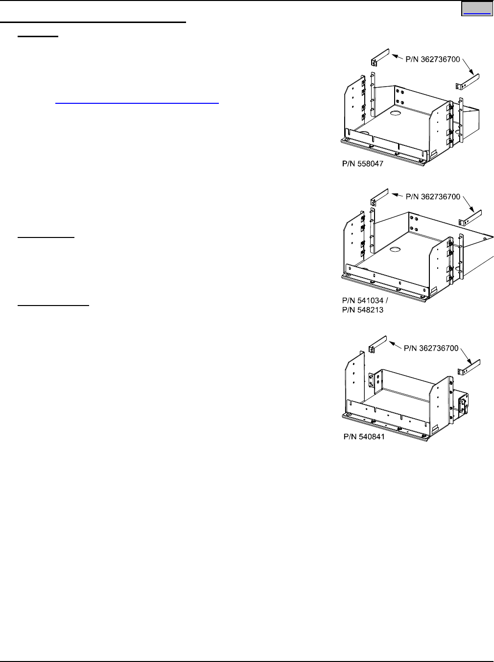
System Application Guide SAG582136600
Spec. No. 582136600 (Model 211NGFB) Issue AU, February 21, 2014
Page 25 of 105
This document is property of Emerson Network Power, Energy Systems, North America, Inc. and contains confidential and proprietary information owned by Emerson Network Power, Energy
Systems, North America, Inc. Any copying, use, or disclosure of it without the written permission of Emerson Network Power, Energy Systems, North America, Inc. is strictly prohibited.
Home
List 94: Battery Tray for 19” Relay Rack
Features
♦ Provides one battery tray that mounts four (4) 12V front terminal
Valve Regulated Lead Acid (VRLA) batteries. Batteries are
configured as one (1) 48V string.
♦ Accepts various VRLA batteries. See Ordering Notes below.
♦ See Overall Dimensions - 19” Battery Tray under PHYSICAL SIZE
INFORMATION for battery tray dimensions and typical
arrangement. Note that three battery trays are available to
accommodate the various size batteries listed in the Ordering
Notes tables.
♦ Trays can be ordered with or without battery disconnect circuit
breakers. When circuit breakers are ordered, one is provided in
the -48V lead of each battery string (1 circuit breaker per tray).
♦ Battery cables are available terminated at the power system end in
an Anderson connector. Battery lugs are available for the remaining
end.
Restrictions
For 19” relay racks only.
Maximum number of List 94’s per rack is three (3).
A single List 94 must mount at bottom of rack. Multiple List 94’s must
mount starting at bottom of rack and working upward.
Ordering Notes
1) Order multiples of List 94 for more than one (1) battery tray. See
Restrictions above.
2) Order one (1) or more P/N 362736700 Cable Bracket(s) as required.
3) Order batteries separately. Tables F, G, H and I list batteries
recommended for use with List 94.
4) Specify rack spacing of 6U (10.5”), 7U (12.25”), or 8U (14”) between
trays and above top tray as required for battery clearance. See
Tables F, G, H and I.
5) Battery lugs are provided, as specified from Table J.
6) Specify with or without battery disconnect circuit breakers.
Note: All List 94 trays in a rack will be furnished with or without battery disconnect circuit breakers as
specified for the first tray ordered.
7) If ordering List 94 with circuit breakers, order one (1) circuit breaker per List 94 from Table K.
8) If ordering List 94 with circuit breakers, specify breaker mounting on left side of tray, right side of tray, or
remote mounting. Circuit breaker mounting kits shown in the Table K will be installed. Kit numbers are
provided for reference only.
9) If ordering List 94 with circuit breakers, order Alarm Jumper P/N 524384 for each system to connect the
alarm terminal of up to three (3) battery disconnect circuit breakers.
SAG582136600 System Application Guide
Issue AU, February 21, 2014 Spec. No. 582136600 (Model 211NGFB)
Page 26 of 105
This document is property of Emerson Network Power, Energy Systems, North America, Inc. and contains confidential and proprietary information owned by Emerson Network Power, Energy
Systems, North America, Inc. Any copying, use, or disclosure of it without the written permission of Emerson Network Power, Energy Systems, North America, Inc. is strictly prohibited.
Home
Battery Tray P/N 558047
Manufacturer* Model
Emerson
Network
Power
P/N
Rated 8-Hr.
Capacity
(Ah)
Dimension
W x L x H
(Inches)
Required
Tray
Spacing
Weight
(per
battery)
(lbs)
Northstar
NSB90FT
--
90
4.25 X 15.59 X 10.04
7U
71
Northstar
NSB100FT
--
100
4.25 X 15.59 X 11.03
7U
78
GNB Marathon
M12V90FT
--
90
4.13 X 15.55 X 10.63
7U
70
Enersys
12TD100F4
--
96
4.3 X 15.5 X 11.3
8U
71
* See Battery Manufacturer Information located at the end of this document.
Table F
Battery Tray P/N 541034
Manufacturer* Model
Emerson
Network
Power
P/N
Rated 8-Hr.
Capacity
(Ah)
Dimension
W x L x H
(Inches)
Required
Tray
Spacing
Weight
(per
battery)
(lbs)
GNB Marathon
M12V105FT
--
105
4.33 X 20.12 X 9.37
7U
79
Enersys
12TD100F6
--
97
4.3 X 20.0 X 9.4
7U
73
* See Battery Manufacturer Information located at the end of this document.
Table G
Battery Tray P/N 540841
Manufacturer* Model
Emerson
Network
Power
P/N
Rated 8-Hr.
Capacity
(Ah)
Dimension
W x L x H
(Inches)
Required
Tray
Spacing
Weight
(per
battery)
(lbs)
Northstar
NSB40FT**
--
38.1
3.80 X 9.80 X 8.20
6U
34
Northstar
NSB60FT**
--
57.9
4.20 X 11.30 X 10.40
7U
49
Douglas
DGS12-25F
--
25
3.94 X 10.80 X 7.60
6U
27
Douglas
DGS12-50F
--
50
3.94 X 10.80 X 11.60
8U
48
Enersys
12TD50F
--
48
4.2 X 10.9 X 8.7
6U
38
* See Battery Manufacturer Information located at the end of this document.
** Batteries MUST be equipped with front access terminal option. See Battery Manufacturer for ordering information.
Table H
System Application Guide SAG582136600
Spec. No. 582136600 (Model 211NGFB) Issue AU, February 21, 2014
Page 27 of 105
This document is property of Emerson Network Power, Energy Systems, North America, Inc. and contains confidential and proprietary information owned by Emerson Network Power, Energy
Systems, North America, Inc. Any copying, use, or disclosure of it without the written permission of Emerson Network Power, Energy Systems, North America, Inc. is strictly prohibited.
Home
Battery Tray P/N 548213
Manufacturer* Model
Emerson
Network
Power P/N
Rated
8-Hr.
Capacit
y (Ah)
Dimension
W x L x H
(Inches)
Required
Tray
Spacing
Weight
(per
battery)
(lbs)
Enersys
12V125F
122009
125
4.10 X 22.10 X 12.40
8U
124
Enersys
12TD150F
--
143
4.3 X 21.7 X 11.3
8U
105
* See Battery Manufacturer Information located at the end of this document.
Table I
Battery
Specified
Battery Lug Kit Part Number
(Kit provides two lugs for one tray.)
Lists 5 and 6 Lists 1 and 2
Northstar NSB90FT
528234
540989
(for use with 10 AWG wire and List 72)
545581
(for use with 8 AWG wire and List 71)
555069
(for use with 6 AWG wire and List 73)
Northstar NSB100FT
GNB Marathon M12V90FT
GNB Marathon M12V105FT
Northstar NSB40FT
Northstar NSB60FT
Douglas DGS12-25F
Douglas DGS12-50F
Enersys 12V125F
Enersys 12TD50F
Enersys 12TD100F4
Enersys 12TD100F6
Enersys 12TD150F
Table J
SAG582136600 System Application Guide
Issue AU, February 21, 2014 Spec. No. 582136600 (Model 211NGFB)
Page 28 of 105
This document is property of Emerson Network Power, Energy Systems, North America, Inc. and contains confidential and proprietary information owned by Emerson Network Power, Energy
Systems, North America, Inc. Any copying, use, or disclosure of it without the written permission of Emerson Network Power, Energy Systems, North America, Inc. is strictly prohibited.
Home
Ampere
Rating
Part No., Circuit Breaker,
Electrical/Mechanical Trip1
(Black Handle)
Part No., Left-Side
Breaker Mtg. Kit
(For Reference Only)
Part No., Right-Side
Breaker Mtg. Kit
(For Reference Only)
1
256690300
528501 528500
3
256690700
5
256691100
10
256691500
15
256691900
20
256692300
25
256692700
30
256693100
35
256693500
40
256693900
50
256694300
60
256694700
70
256695100
75
256695500
100
256695900
1 Provides an alarm during an electrical or manual trip condition.
Table K
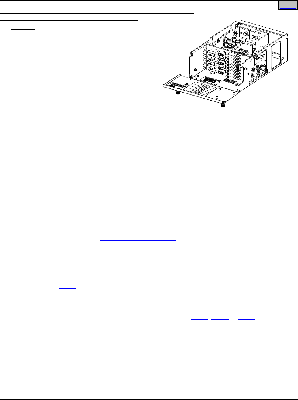
System Application Guide SAG582136600
Spec. No. 582136600 (Model 211NGFB) Issue AU, February 21, 2014
Page 29 of 105
This document is property of Emerson Network Power, Energy Systems, North America, Inc. and contains confidential and proprietary information owned by Emerson Network Power, Energy
Systems, North America, Inc. Any copying, use, or disclosure of it without the written permission of Emerson Network Power, Energy Systems, North America, Inc. is strictly prohibited.
Home
List BF: Distribution Unit with GMT Fuse Load Distribution Positions
and with Low Voltage Battery Disconnect (LVBD)
Features
♦ Provides a Distribution Unit with Low Voltage
Battery Disconnect (LVBD), a battery shunt, (3)
battery connection points, and thirteen (13) GMT
fuse load distribution positions.
♦ Five (5) 0A to 15A GMT fuse load distribution
positions.
♦ Eight (8) 0A to 10A GMT fuse load distribution
positions.
Restrictions
For use with List 5 and 6 only.
The (13) Position GMT Fuse Printed Wiring Board is rated 100A at +40°C (+104°F) and 59.5A at 65°C
(+149°F).
Unless otherwise specified fuses are mounted from bottom to top, starting with the highest capacity and
working to the lowest capacity.
In an ambient of 40°C (+104°F):
• Fuseholders F1-F8 are rated for a 10A fuse maximum. An empty space is not required between fuses of
any value.
• Fuseholders F9-F13 are rated for a 15A fuse maximum. An empty space is not required between fuses
of any value. However, 15A fuses cannot be placed in adjacent fuseholders. 15A fuses must be
separated by a smaller fuse or a space.
In an ambient of 65°C (+149°F):
• Fuseholders F1-F8 are rated for a 10A fuse maximum. An empty space is required between 10A fuses.
A fuse greater than 3A cannot be placed in a fuseholder adjacent to a 10A fuse.
• Fuseholders F9-F13 are rated for a 15A fuse maximum. An empty space is required between 15A fuses.
10A fuses cannot be placed in adjacent fuseholders. A fuse greater than 3A cannot be placed in a
fuseholder adjacent to a 10A fuse.
See also the Restrictions under “GMT Load Distribution Fuses” in the ACCESSORY DESCRIPTIONS
section.
Ordering Notes
1) Order one (1) Distribution Unit (List BF, LF, NF, BC, LC, NC, BA, LA, or NA) for each List 5 or 6 shelf.
Also order the following as required.
2) Order Distribution Devices per ACCESSORY DESCRIPTIONS section.
3) Order one (1) List 61 for each List BF. Each List 61 provides eight (8) GMT fuse load lead assemblies for
the 10A fuse blocks.
4) Order one (1) List 62 for each List BF. Each List 62 provides five (5) GMT fuse load lead assemblies for
the 15A fuse blocks.
5) Order Shelf Side, Battery Side Battery Cables or Output Cables (List 65, List 66 or List 67) as required.
List 65 and List 67 are factory installed.
6) The controller remains powered when the LVBD contactor opens. Specify if you require List BF to be
factory configured for the controller not to be powered when the LVBD contactor opens.
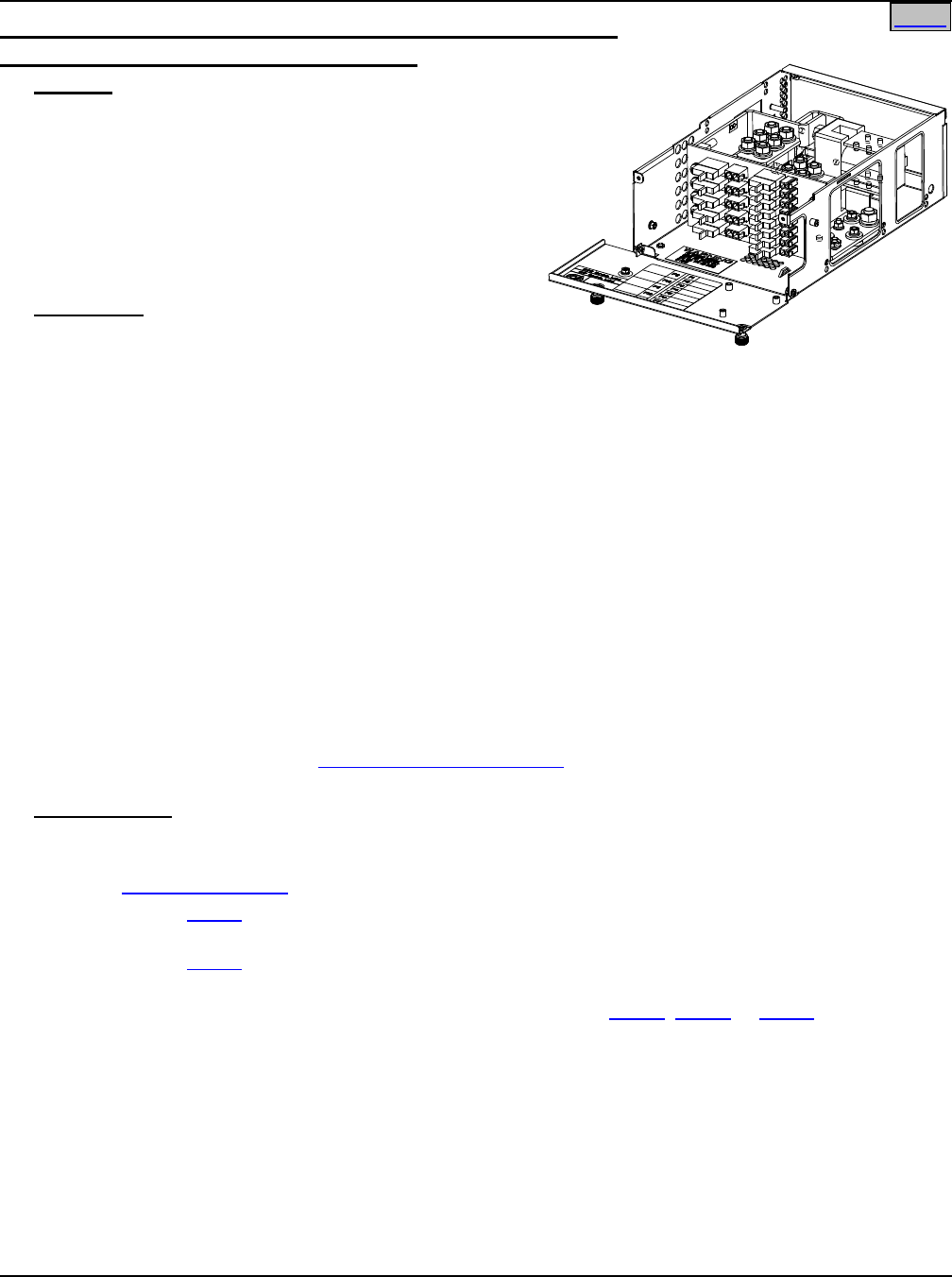
SAG582136600 System Application Guide
Issue AU, February 21, 2014 Spec. No. 582136600 (Model 211NGFB)
Page 30 of 105
This document is property of Emerson Network Power, Energy Systems, North America, Inc. and contains confidential and proprietary information owned by Emerson Network Power, Energy
Systems, North America, Inc. Any copying, use, or disclosure of it without the written permission of Emerson Network Power, Energy Systems, North America, Inc. is strictly prohibited.
Home
List LF: Distribution Unit with GMT Fuse Load Distribution Positions
and with Low Voltage Load Disconnect (LVLD)
Features
♦ Provides a Distribution Unit with Low Voltage Load
Disconnect (LVLD), a battery shunt, (3) battery
connection points, and thirteen (13) GMT fuse load
distribution positions.
♦ Five (5) 0A to 15A GMT fuse load distribution
positions.
♦ Eight (8) 0A to 10A GMT fuse load distribution
positions.
Restrictions
For use with List 5 and 6 only.
The (13) Position GMT Fuse Printed Wiring Board is rated
100A at +40°C (+104°F) and 59.5A at 65°C (+149°F).
Unless otherwise specified fuses are mounted from bottom to top, starting with the highest capacity and
working to the lowest capacity.
In an ambient of 40°C (+104°F):
• Fuseholders F1-F8 are rated for a 10A fuse maximum. An empty space is not required between fuses of
any value.
• Fuseholders F9-F13 are rated for a 15A fuse maximum. An empty space is not required between fuses
of any value. However, 15A fuses cannot be placed in adjacent fuseholders. 15A fuses must be
separated by a smaller fuse or a space.
In an ambient of 65°C (+149°F):
• Fuseholders F1-F8 are rated for a 10A fuse maximum. An empty space is required between 10A fuses.
A fuse greater than 3A cannot be placed in a fuseholder adjacent to a 10A fuse.
• Fuseholders F9-F13 are rated for a 15A fuse maximum. An empty space is required between 15A fuses.
10A fuses cannot be placed in adjacent fuseholders. A fuse greater than 3A cannot be placed in a
fuseholder adjacent to a 10A fuse.
See also the Restrictions under “GMT Load Distribution Fuses” in the ACCESSORY DESCRIPTIONS
section.
Ordering Notes
1) Order one (1) Distribution Unit (List BF, LF, NF, BC, LC, NC, BA, LA, or NA) for each List 5 or 6 shelf.
Also order the following as required.
2) Order Distribution Devices per ACCESSORY DESCRIPTIONS section.
3) Order one (1) List 61 for each List LF. Each List 61 provides eight (8) GMT fuse load lead assemblies for
the 10A fuse blocks.
4) Order one (1) List 62 for each List LF. Each List 62 provides five (5) GMT fuse load lead assemblies for
the 15A fuse blocks.
5) Order Shelf Side, Battery Side Battery Cables or Output Cables (List 65, List 66 or List 67) as required.
List 65 and List 67 are factory installed.
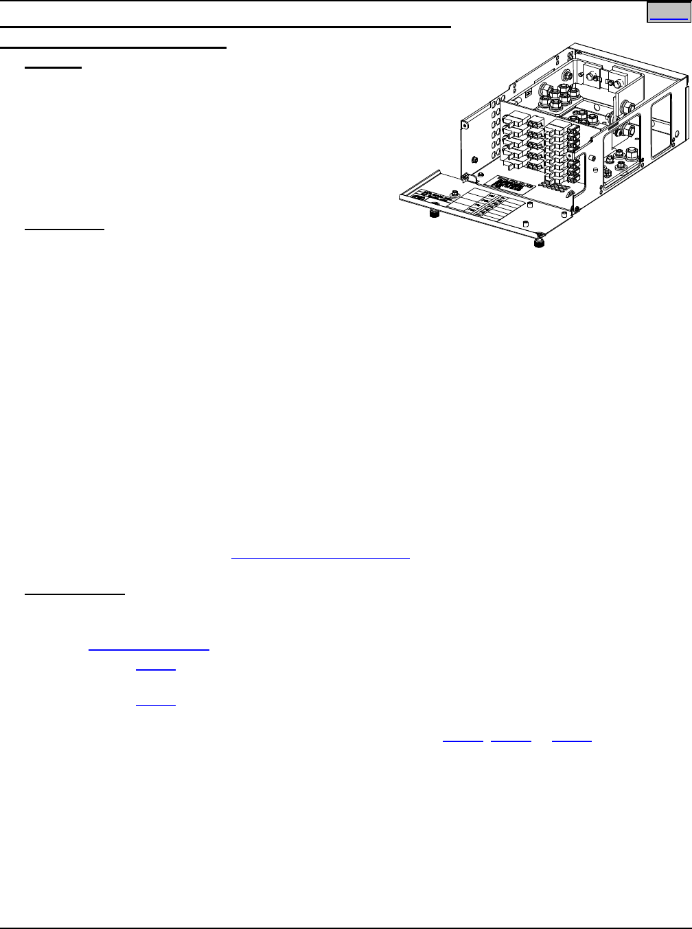
System Application Guide SAG582136600
Spec. No. 582136600 (Model 211NGFB) Issue AU, February 21, 2014
Page 31 of 105
This document is property of Emerson Network Power, Energy Systems, North America, Inc. and contains confidential and proprietary information owned by Emerson Network Power, Energy
Systems, North America, Inc. Any copying, use, or disclosure of it without the written permission of Emerson Network Power, Energy Systems, North America, Inc. is strictly prohibited.
Home
List NF: Distribution Unit with GMT Fuse Load Distribution Positions
and w/out Low Voltage Disconnect
Features
♦ Provides a Distribution Unit w/out low voltage
disconnect, a battery shunt, (3) battery connection
points, and thirteen (13) GMT fuse load distribution
positions.
♦ Five (5) 0A to 15A GMT fuse load distribution
positions.
♦ Eight (8) 0A to 10A GMT fuse load distribution
positions.
Restrictions
For use with List 5 and 6 only.
The (13) Position GMT Fuse Printed Wiring Board is rated 100A at +40°C (+104°F) and 59.5A at 65°C
(+149°F).
Unless otherwise specified fuses are mounted from bottom to top, starting with the highest capacity and
working to the lowest capacity.
In an ambient of 40°C (+104°F):
• Fuseholders F1-F8 are rated for a 10A fuse maximum. An empty space is not required between fuses of
any value.
• Fuseholders F9-F13 are rated for a 15A fuse maximum. An empty space is not required between fuses
of any value. However, 15A fuses cannot be placed in adjacent fuseholders. 15A fuses must be
separated by a smaller fuse or a space.
In an ambient of 65°C (+149°F):
• Fuseholders F1-F8 are rated for a 10A fuse maximum. An empty space is required between 10A fuses.
A fuse greater than 3A cannot be placed in a fuseholder adjacent to a 10A fuse.
• Fuseholders F9-F13 are rated for a 15A fuse maximum. An empty space is required between 15A fuses.
10A fuses cannot be placed in adjacent fuseholders. A fuse greater than 3A cannot be placed in a
fuseholder adjacent to a 10A fuse.
See also the Restrictions under “GMT Load Distribution Fuses” in the ACCESSORY DESCRIPTIONS
section.
Ordering Notes
1) Order one (1) Distribution Unit (List BF, LF, NF, BC, LC, NC, BA, LA, or NA) for each List 5 or 6 shelf.
Also order the following as required.
2) Order Distribution Devices per ACCESSORY DESCRIPTIONS section.
3) Order one (1) List 61 for each List NF. Each List 61 provides eight (8) GMT fuse load lead assemblies for
the 10A fuse blocks.
4) Order one (1) List 62 for each List NF. Each List 62 provides five (5) GMT fuse load lead assemblies for
the 15A fuse blocks.
5) Order Shelf Side, Battery Side Battery Cables or Output Cables (List 65, List 66 or List 67) as required.
List 65 and List 67 are factory installed.
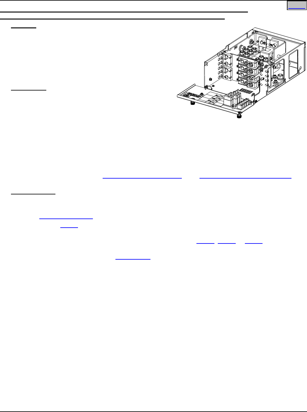
SAG582136600 System Application Guide
Issue AU, February 21, 2014 Spec. No. 582136600 (Model 211NGFB)
Page 32 of 105
This document is property of Emerson Network Power, Energy Systems, North America, Inc. and contains confidential and proprietary information owned by Emerson Network Power, Energy
Systems, North America, Inc. Any copying, use, or disclosure of it without the written permission of Emerson Network Power, Energy Systems, North America, Inc. is strictly prohibited.
Home
List BC: Distribution Unit with GMT Fuse Load Distribution Positions, Circuit Breaker
Load Distribution Positions, and with Low Voltage Battery Disconnect (LVBD)
Features
♦ Provides a Distribution Unit with Low Voltage Battery
Disconnect (LVBD), a battery shunt, (3) battery
connection points, four (4) bullet nose-type circuit
breaker load distribution positions, five (5) GMT fuse
load distribution positions.
♦ Five (5) 0A to 10A GMT fuse load distribution
positions.
Restrictions
For use with List 5 and 6 only.
Maximum distribution current is 72A at @ +65°C (+149°F)
and 100A @ +40°C (+104°F).
The GMT fuse block has a 35A @ +40°C (+104°F) and a
21A @ +65°C (+149°F) maximum capacity. Maximum GMT fuse size is 10A. At +65°C (+149°F), a space is
required between GMT fuses greater than 5A.
Maximum load distribution circuit breaker size is 75A @ +65°C (+149°F).
Caution: In an ambient of +65°C (+149°F), a circuit breaker with a rating greater than 45 amperes
SHALL HAVE an empty mounting position between it and any other overcurrent protective
device. There are no restrictions in an ambient of +40°C (+104°F).
See also the Restrictions under “GMT Load Distribution Fuses” and “Bullet Nose-Type Circuit Breakers” in
the ACCESSORY DESCRIPTIONS section.
Ordering Notes
1) Order one (1) Distribution Unit (List BF, LF, NF, BC, LC, NC, BA, LA, or NA) for each List 5 or 6 shelf.
Also order the following as required.
2) Order Distribution Devices per ACCESSORY DESCRIPTIONS section.
3) Order one (1) List 60 for each List BC. Each List 60 provides five (5) GMT fuse load lead assemblies for
the 10A fuse blocks.
4) Order Shelf Side, Battery Side Battery Cables or Output Cables (List 65, List 66 or List 67) as required.
List 65 and List 67 are factory installed.
5) Order circuit breaker load lugs per Wiring Notes under ACCESSORY DESCRIPTIONS section.
6) The controller remains powered when the LVBD contactor opens. Specify if you require List BC to be
factory configured for the controller not to be powered when the LVBD contactor opens.
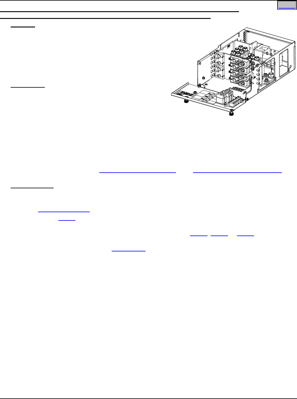
System Application Guide SAG582136600
Spec. No. 582136600 (Model 211NGFB) Issue AU, February 21, 2014
Page 33 of 105
This document is property of Emerson Network Power, Energy Systems, North America, Inc. and contains confidential and proprietary information owned by Emerson Network Power, Energy
Systems, North America, Inc. Any copying, use, or disclosure of it without the written permission of Emerson Network Power, Energy Systems, North America, Inc. is strictly prohibited.
Home
List LC: Distribution Unit with GMT Fuse Load Distribution Positions, Circuit Breaker
Load Distribution Positions, and with Low Voltage Load Disconnect (LVLD)
Features
♦ Provides a Distribution Unit with Low Voltage Load
Disconnect (LVLD), a battery shunt, (3) battery
connection points, four (4) bullet nose-type circuit
breaker load distribution positions, five (5) GMT fuse
load distribution positions.
♦ Five (5) 0A to 10A GMT fuse load distribution
positions.
Restrictions
For use with List 5 and 6 only.
Maximum distribution current is 72A at @ +65°C (+149°F)
and 100A @ +40°C (+104°F).
The GMT fuse block has a 35A @ +40°C (+104°F) and a
21A @ +65°C (+149°F) maximum capacity. Maximum GMT fuse size is 10A. At +65°C (+149°F), a space is
required between GMT fuses greater than 5A.
Maximum load distribution circuit breaker size is 75A @ +65°C (+149°F).
Caution: In an ambient of +65°C (+149°F), a circuit breaker with a rating greater than 45 amperes
SHALL HAVE an empty mounting position between it and any other overcurrent protective
device. There are no restrictions in an ambient of +40°C (+104°F).
See also the Restrictions under “GMT Load Distribution Fuses” and “Bullet Nose-Type Circuit Breakers” in
the ACCESSORY DESCRIPTIONS section.
Ordering Notes
1) Order one (1) Distribution Unit (List BF, LF, NF, BC, LC, NC, BA, LA, or NA) for each List 5 or 6 shelf.
Also order the following as required.
2) Order Distribution Devices per ACCESSORY DESCRIPTIONS section.
3) Order one (1) List 60 for each List LC. Each List 60 provides five (5) GMT fuse load lead assemblies for
the 10A fuse blocks.
4) Order Shelf Side, Battery Side Battery Cables or Output Cables (List 65, List 66 or List 67) as required.
List 65 and List 67 are factory installed.
5) Order circuit breaker load lugs per Wiring Notes under ACCESSORY DESCRIPTIONS section.
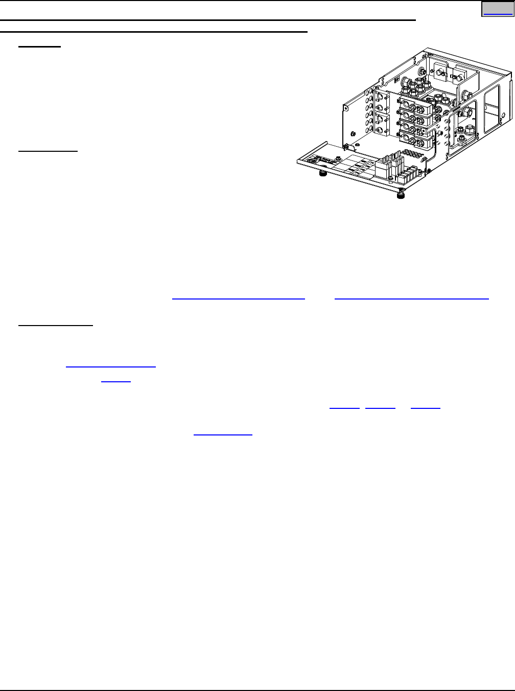
SAG582136600 System Application Guide
Issue AU, February 21, 2014 Spec. No. 582136600 (Model 211NGFB)
Page 34 of 105
This document is property of Emerson Network Power, Energy Systems, North America, Inc. and contains confidential and proprietary information owned by Emerson Network Power, Energy
Systems, North America, Inc. Any copying, use, or disclosure of it without the written permission of Emerson Network Power, Energy Systems, North America, Inc. is strictly prohibited.
Home
List NC: Distribution Unit with GMT Fuse Load Distribution Positions, Circuit Breaker
Load Distribution Positions, and w/out Low Voltage Disconnect
Features
♦ Provides a Distribution Unit w/out low voltage
disconnect, a battery shunt, (3) battery connection
points, four (4) bullet nose-type circuit breaker load
distribution positions, five (5) GMT fuse load
distribution positions.
♦ Five (5) 0A to 10A GMT fuse load distribution
positions.
Restrictions
For use with List 5 and 6 only.
Maximum distribution current is 72A at @ +65°C (+149°F)
and 100A @ +40°C (+104°F).
The GMT fuse block has a 35A @ +40°C (+104°F) and a
21A @ +65°C (+149°F) maximum capacity. Maximum GMT fuse size is 10A. At +65°C (+149°F), a space is
required between GMT fuses greater than 5A.
Maximum load distribution circuit breaker size is 75A @ +65°C (+149°F).
Caution: In an ambient of +65°C (+149°F), a circuit breaker with a rating greater than 45 amperes
SHALL HAVE an empty mounting position between it and any other overcurrent protective
device. There are no restrictions in an ambient of +40°C (+104°F).
See also the Restrictions under “GMT Load Distribution Fuses” and “Bullet Nose-Type Circuit Breakers” in
the ACCESSORY DESCRIPTIONS section.
Ordering Notes
1) Order one (1) Distribution Unit (List BF, LF, NF, BC, LC, NC, BA, LA, or NA) for each List 5 or 6 shelf.
Also order the following as required.
2) Order Distribution Devices per ACCESSORY DESCRIPTIONS section.
3) Order one (1) List 60 for each List NC. Each List 60 provides five (5) GMT fuse load lead assemblies for
the 10A fuse blocks.
4) Order Shelf Side, Battery Side Battery Cables or Output Cables (List 65, List 66 or List 67) as required.
List 65 and List 67 are factory installed.
5) Order circuit breaker load lugs per Wiring Notes under ACCESSORY DESCRIPTIONS section.
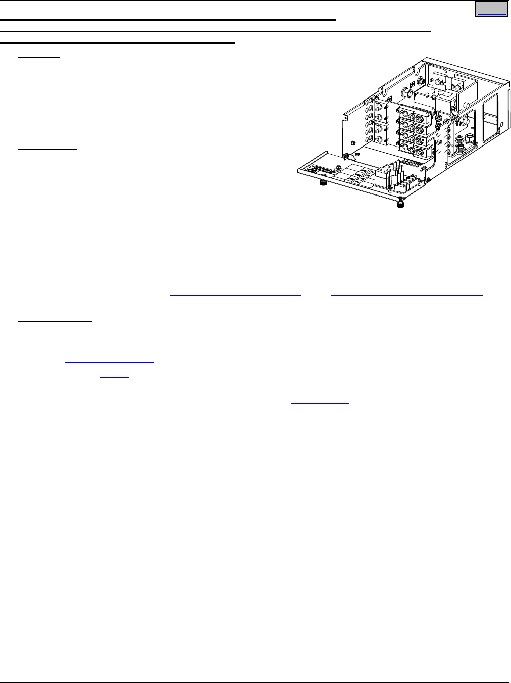
System Application Guide SAG582136600
Spec. No. 582136600 (Model 211NGFB) Issue AU, February 21, 2014
Page 35 of 105
This document is property of Emerson Network Power, Energy Systems, North America, Inc. and contains confidential and proprietary information owned by Emerson Network Power, Energy
Systems, North America, Inc. Any copying, use, or disclosure of it without the written permission of Emerson Network Power, Energy Systems, North America, Inc. is strictly prohibited.
Home
List BA: Distribution Unit with GMT Fuse Load Distribution Positions,
Circuit Breaker Load Distribution Positions, Circuit Breaker Battery Disconnect Positions,
and with Low Voltage Battery Disconnect (LVBD)
Features
♦ Provides a Distribution Unit with Low Voltage Battery
Disconnect (LVBD), a battery shunt, two (2) bullet
nose-type circuit breaker load distribution positions, two
(2) bullet nose-type circuit breaker battery disconnect
positions, five (5) GMT fuse load distribution positions.
♦ Five (5) 0A to 10A GMT fuse load distribution positions.
Restrictions
For use with List 5 and 6 only.
Maximum distribution current is 72A at @ +65°C (+149°F)
and 100A @ +40°C (+104°F).
The GMT fuse block has a 35A @ +40°C (+104°F) and a
21A @ +65°C (+149°F) maximum capacity. Maximum
GMT fuse size is 10A. At +65°C (+149°F), a space is required between GMT fuses greater than 5A.
Maximum load distribution or battery circuit breaker size is 75A @ +65°C (+149°F).
Caution: In an ambient of +65°C (+149°F), a circuit breaker with a rating greater than 45 amperes
SHALL HAVE an empty mounting position between it and any other overcurrent protective
device. There are no restrictions in an ambient of +40°C (+104°F).
See also the Restrictions under “GMT Load Distribution Fuses” and “Bullet Nose-Type Circuit Breakers” in
the ACCESSORY DESCRIPTIONS section.
Ordering Notes
1) Order one (1) Distribution Unit (List BF, LF, NF, BC, LC, NC, BA, LA, or NA) for each List 5 or 6 shelf.
Also order the following as required.
2) Order Distribution Devices per ACCESSORY DESCRIPTIONS section.
3) Order one (1) List 60 for each List BA. Each List 60 provides five (5) GMT fuse load lead assemblies for
the 10A fuse blocks.
4) Order circuit breaker load lugs and battery input lugs per Wiring Notes under ACCESSORY
DESCRIPTIONS section.
5) The controller remains powered when the LVBD contactor opens. Specify if you require List BA to be
factory configured for the controller not to be powered when the LVBD contactor opens.
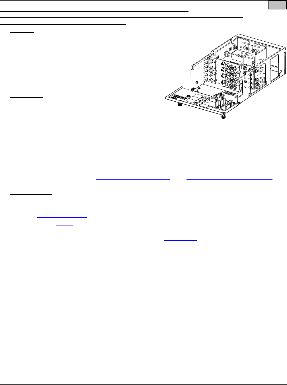
SAG582136600 System Application Guide
Issue AU, February 21, 2014 Spec. No. 582136600 (Model 211NGFB)
Page 36 of 105
This document is property of Emerson Network Power, Energy Systems, North America, Inc. and contains confidential and proprietary information owned by Emerson Network Power, Energy
Systems, North America, Inc. Any copying, use, or disclosure of it without the written permission of Emerson Network Power, Energy Systems, North America, Inc. is strictly prohibited.
Home
List LA: Distribution Unit with GMT Fuse Load Distribution Positions,
Circuit Breaker Load Distribution Positions, Circuit Breaker Battery Disconnect Positions,
and with Low Voltage Load Disconnect (LVLD)
Features
♦ Provides a Distribution Unit with Low Voltage Load
Disconnect (LVLD), a battery shunt, two (2) bullet
nose-type circuit breaker load distribution positions,
two (2) bullet nose-type circuit breaker battery
disconnect positions, five (5) GMT fuse load
distribution positions.
♦ Five (5) 0A to 10A GMT fuse load distribution
positions.
Restrictions
For use with List 5 and 6 only.
Maximum distribution current is 72A at @ +65°C (+149°F)
and 100A @ +40°C (+104°F).
The GMT fuse block has a 35A @ +40°C (+104°F) and a 21A @ +65°C (+149°F) maximum capacity.
Maximum GMT fuse size is 10A. At +65°C (+149°F), a space is required between GMT fuses greater than
5A.
Maximum load distribution or battery circuit breaker size is 75A @ +65°C (+149°F).
Caution: In an ambient of +65°C (+149°F), a circuit breaker with a rating greater than 45 amperes
SHALL HAVE an empty mounting position between it and any other overcurrent protective
device. There are no restrictions in an ambient of +40°C (+104°F).
See also the Restrictions under “GMT Load Distribution Fuses” and “Bullet Nose-Type Circuit Breakers” in
the ACCESSORY DESCRIPTIONS section.
Ordering Notes
1) Order one (1) Distribution Unit (List BF, LF, NF, BC, LC, NC, BA, LA, or NA) for each List 5 or 6 shelf.
Also order the following as required.
2) Order Distribution Devices per ACCESSORY DESCRIPTIONS section.
3) Order one (1) List 60 for each List LA. Each List 60 provides five (5) GMT fuse load lead assemblies for
the 10A fuse blocks.
4) Order circuit breaker load lugs and battery input lugs per Wiring Notes under ACCESSORY
DESCRIPTIONS section.
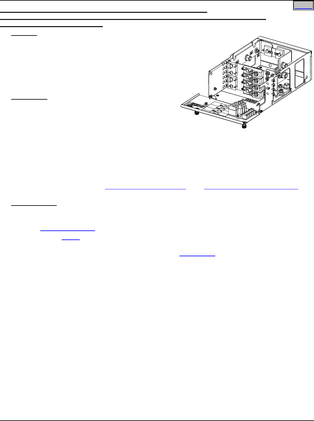
System Application Guide SAG582136600
Spec. No. 582136600 (Model 211NGFB) Issue AU, February 21, 2014
Page 37 of 105
This document is property of Emerson Network Power, Energy Systems, North America, Inc. and contains confidential and proprietary information owned by Emerson Network Power, Energy
Systems, North America, Inc. Any copying, use, or disclosure of it without the written permission of Emerson Network Power, Energy Systems, North America, Inc. is strictly prohibited.
Home
List NA: Distribution Unit with GMT Fuse Load Distribution Positions,
Circuit Breaker Load Distribution Positions, Circuit Breaker Battery Disconnect Positions,
and w/out Low Voltage Disconnect
Features
♦ Provides a Distribution Unit w/out low voltage
disconnect, a battery shunt, two (2) bullet nose-type
circuit breaker load distribution positions, two (2) bullet
nose-type circuit breaker battery disconnect positions,
five (5) GMT fuse load distribution positions.
♦ Five (5) 0A to 10A GMT fuse load distribution
positions.
Restrictions
For use with List 5 and 6 only.
Maximum distribution current is 72A at @ +65°C (+149°F)
and 100A @ +40°C (+104°F).
The GMT fuse block has a 35A @ +40°C (+104°F) and a
21A @ +65°C (+149°F) maximum capacity. Maximum GMT fuse size is 10A. At +65°C (+149°F), a space is
required between GMT fuses greater than 5A.
Maximum load distribution or battery circuit breaker size is 75A @ +65°C (+149°F).
Caution: In an ambient of +65°C (+149°F), a circuit breaker with a rating greater than 45 amperes
SHALL HAVE an empty mounting position between it and any other overcurrent protective
device. There are no restrictions in an ambient of +40°C (+104°F).
See also the Restrictions under “GMT Load Distribution Fuses” and “Bullet Nose-Type Circuit Breakers” in
the ACCESSORY DESCRIPTIONS section.
Ordering Notes
1) Order one (1) Distribution Unit (List BF, LF, NF, BC, LC, NC, BA, LA, or NA) for each List 5 or 6 shelf.
Also order the following as required.
2) Order Distribution Devices per ACCESSORY DESCRIPTIONS section.
3) Order one (1) List 60 for each List NA. Each List 60 provides five (5) GMT fuse load lead assemblies for
the 10A fuse blocks.
4) Order circuit breaker load lugs and battery input lugs per Wiring Notes under ACCESSORY
DESCRIPTIONS section.
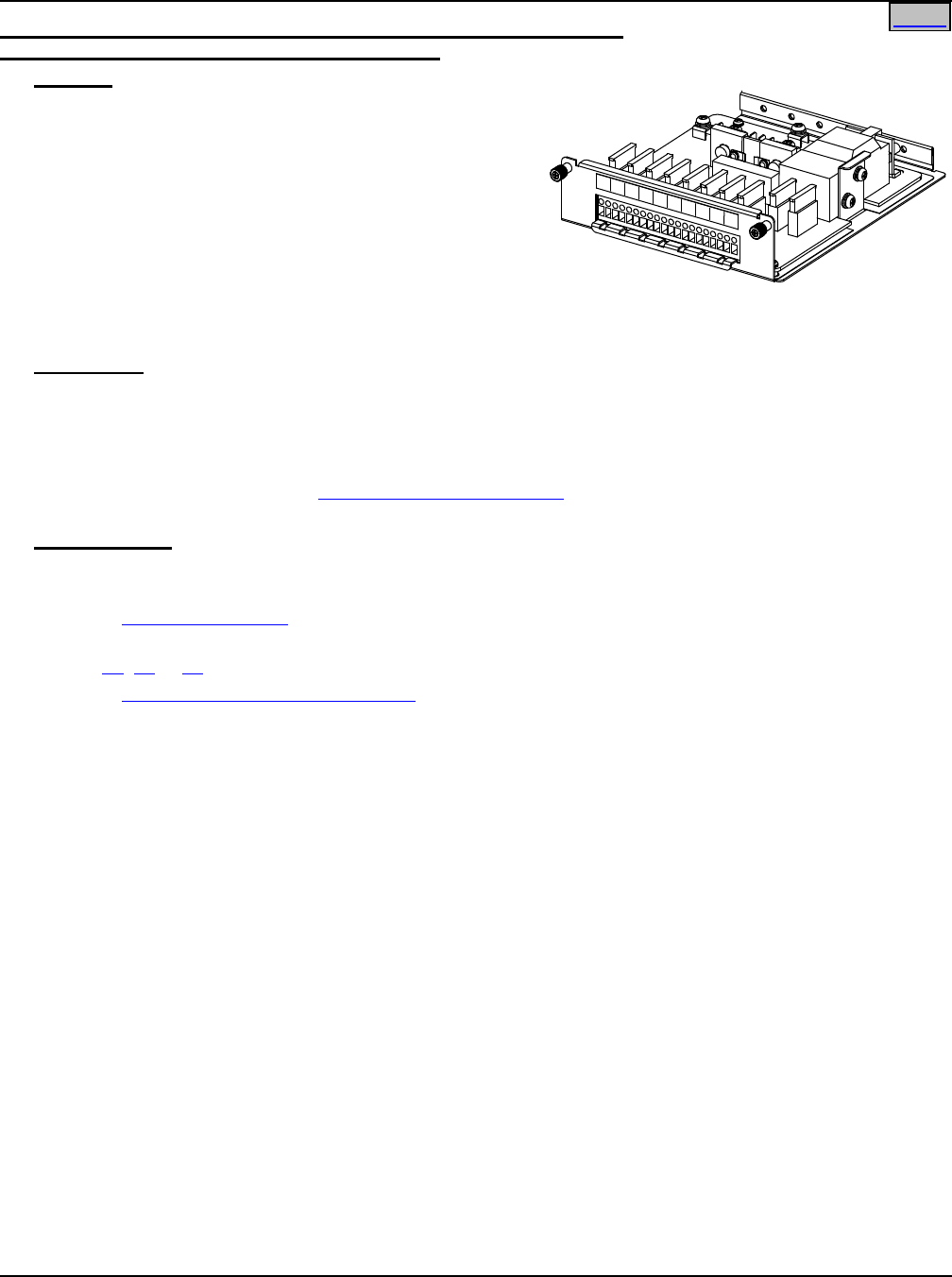
SAG582136600 System Application Guide
Issue AU, February 21, 2014 Spec. No. 582136600 (Model 211NGFB)
Page 38 of 105
This document is property of Emerson Network Power, Energy Systems, North America, Inc. and contains confidential and proprietary information owned by Emerson Network Power, Energy
Systems, North America, Inc. Any copying, use, or disclosure of it without the written permission of Emerson Network Power, Energy Systems, North America, Inc. is strictly prohibited.
Home
List BG: Distribution Unit with GMT Fuse Load Distribution Positions
and with Low Voltage Battery Disconnect (LVBD)
Features
♦ Provides a Distribution Unit with Low Voltage Battery
Disconnect (LVBD), battery cables, and ten (10) GMT
fuse load distribution positions (15A maximum).
♦ Two (2) 8 AWG 48” long battery cables are factory
connected inside the shelf. These cables are
terminated at the customer end in a Red SB50
Anderson battery connector. A mating Anderson
battery connector is provided [Housing: Emerson P/N
138922, Anderson Power Products P/N 992G1.
Contacts (two provided): Emerson P/N 247109602, Anderson Power Products P/N 5952].
♦ Ten (10) 0A to 15A GMT fuse load distribution positions.
Restrictions
For use with List 1 and 2 only.
The Distribution Unit has a 50A @ +40°C (+104°F) and 40A @ +65°C (+149°F) maximum capacity.
Maximum GMT fuse size is 15A. In an ambient of +65°C (+149°F), an empty space is required between 15A
fuses.
See also the Restrictions under “GMT Load Distribution Fuses” in the ACCESSORY DESCRIPTIONS
section.
Ordering Notes
1) Order one (1) Distribution Unit (List BG or NG) for each List 1 or 2 shelf.
Also order the following as required.
2) Order Distribution Devices per ACCESSORY DESCRIPTIONS section.
3) Order Optional External Battery Cables with Anderson Connector for one (1) to two (2) Battery Strings per
List 71, 72 or 73.
4) Order Spare Anderson Battery Connector per ACCESSORY DESCRIPTIONS section.
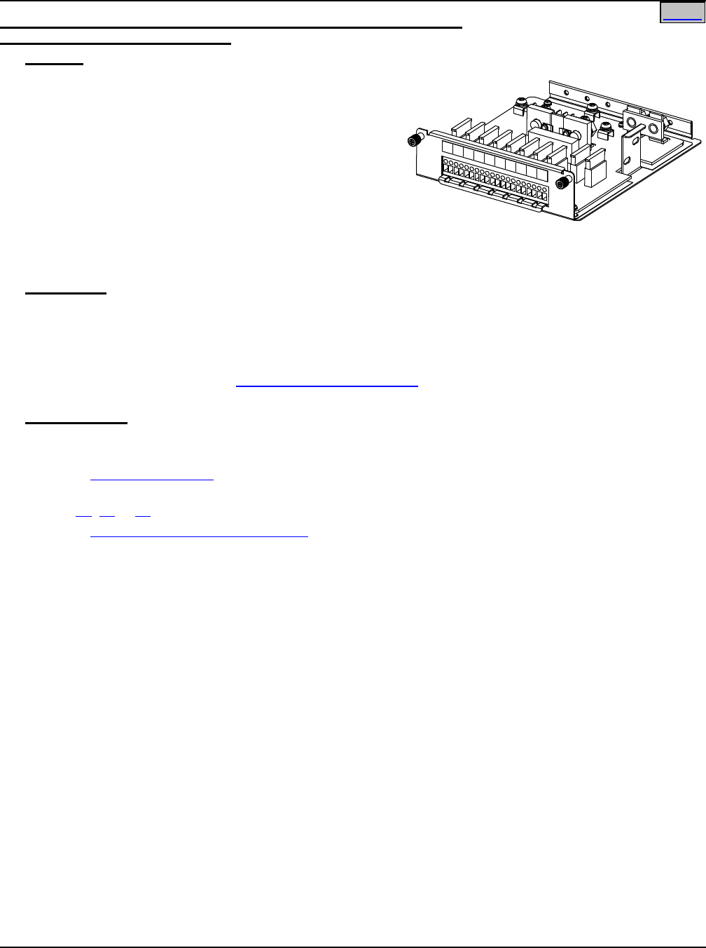
System Application Guide SAG582136600
Spec. No. 582136600 (Model 211NGFB) Issue AU, February 21, 2014
Page 39 of 105
This document is property of Emerson Network Power, Energy Systems, North America, Inc. and contains confidential and proprietary information owned by Emerson Network Power, Energy
Systems, North America, Inc. Any copying, use, or disclosure of it without the written permission of Emerson Network Power, Energy Systems, North America, Inc. is strictly prohibited.
Home
List NG: Distribution Unit with GMT Fuse Load Distribution Positions
and w/out Low Voltage Disconnect
Features
♦ Provides a Distribution Unit w/out low voltage
disconnect, a battery shunt, battery cables, and ten
(10) GMT fuse load distribution positions (15A
maximum).
♦ Two (2) 8 AWG 48” long battery cables are factory
connected inside the shelf. These cables are
terminated at the customer end in a Red SB50
Anderson battery connector. A mating Anderson
battery connector is provided [Housing: Emerson P/N
138922, Anderson Power Products P/N 992G1.
Contacts (two provided): Emerson P/N 247109602, Anderson Power Products P/N 5952].
♦ Ten (10) 0A to 15A GMT fuse load distribution positions.
Restrictions
For use with List 1 and 2 only.
The Distribution Unit has a 50A @ +40°C (+104°F) and 40A @ +65°C (+149°F) maximum capacity.
Maximum GMT fuse size is 15A. In an ambient of +65°C (+149°F), an empty space is required between 15A
fuses.
See also the Restrictions under “GMT Load Distribution Fuses” in the ACCESSORY DESCRIPTIONS
section.
Ordering Notes
1) Order one (1) Distribution Unit (List BG or NG) for each List 1 or 2 shelf.
Also order the following as required.
2) Order Distribution Devices per ACCESSORY DESCRIPTIONS section.
3) Order Optional External Battery Cables with Anderson Connector for one (1) to two (2) Battery Strings per
List 71, 72 or 73.
4) Order Spare Anderson Battery Connector per ACCESSORY DESCRIPTIONS section.
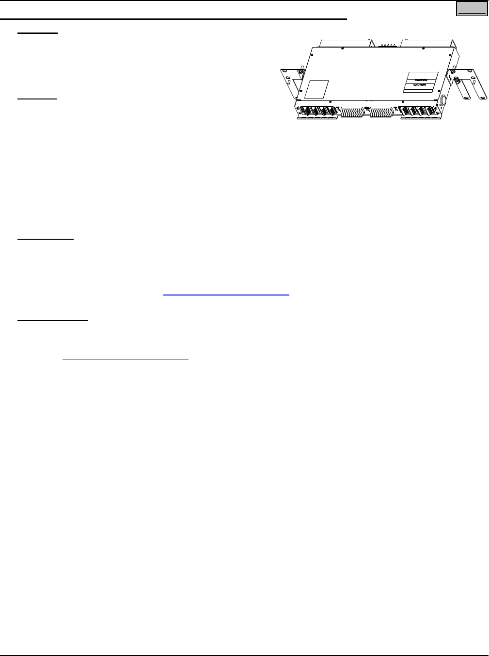
SAG582136600 System Application Guide
Issue AU, February 21, 2014 Spec. No. 582136600 (Model 211NGFB)
Page 40 of 105
This document is property of Emerson Network Power, Energy Systems, North America, Inc. and contains confidential and proprietary information owned by Emerson Network Power, Energy
Systems, North America, Inc. Any copying, use, or disclosure of it without the written permission of Emerson Network Power, Energy Systems, North America, Inc. is strictly prohibited.
Home
List KG: Distribution Panel with (20) GMT Fuse Load Distribution Positions
Features
♦ 1U-high GMT fuse panel that provides Single Load
Distribution (-48V)
♦ Provides twenty (20) 0A to 15A GMT fuse load
distribution positions.
Caution: At +40°C and +65°C ambient, a fuse with a
rating of greater than 10 amperes SHALL
HAVE an empty mounting position between
it and any other fuse.
♦ Maximum Capacity: 80A @ +40°C and 80A @ +65°C
♦ Factory mounted and connected to List 5 or 6 shelf.
♦ If the Distribution Unit in the system is equipped with Low Voltage Load Disconnect (LVLD), all List KG
loads are disconnected.
♦ If one or more distribution fuses opens, one set of Form-C relay contacts changes state, and resistive
battery is provided to an alarm terminal. Alarm circuit is factory connected to activate the Power System
Controller fuse alarm
Restrictions
For use with List 5 and 6 only.
Mounts only immediately above List 5 or 6 shelf.
Maximum distribution current is 80A.
See also the Restrictions under “GMT Load Distribution Fuses” in the ACCESSORY DESCRIPTIONS
section.
Ordering Notes
1) Order one (1) List KG GMT Distribution Fuse Panel Assembly for each List 5 or 6 shelf as required.
Also order the following as required.
2) Order GMT Load Distribution Fuses per ACCESSORY DESCRIPTIONS section.
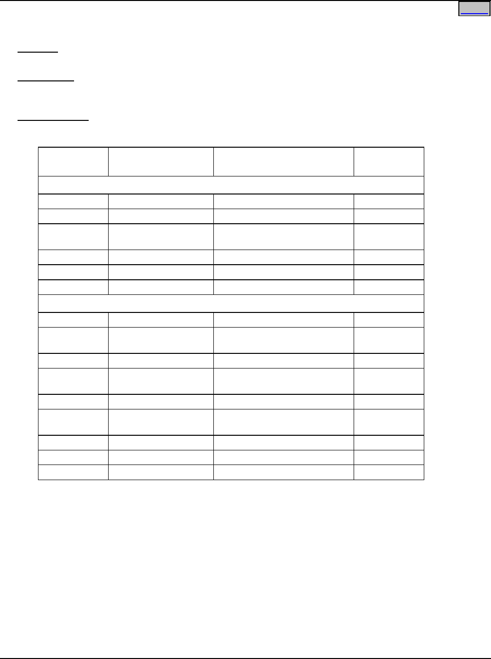
System Application Guide SAG582136600
Spec. No. 582136600 (Model 211NGFB) Issue AU, February 21, 2014
Page 41 of 105
This document is property of Emerson Network Power, Energy Systems, North America, Inc. and contains confidential and proprietary information owned by Emerson Network Power, Energy
Systems, North America, Inc. Any copying, use, or disclosure of it without the written permission of Emerson Network Power, Energy Systems, North America, Inc. is strictly prohibited.
Home
ACCESSORY DESCRIPTIONS
Relay Racks
Features
♦ The following relay racks are available.
Restrictions
Customer must mount Power/Distribution Shelf in relay rack. If battery trays are ordered, they are factory
mounted in the relay rack.
Ordering Notes
1) Order from relay racks listed in Table 1.
Part
Number Size Available Mounting
Positions (1RU = 1-3/4”) Notes
23” Relay Racks
543156
51-3/8” H x 23” W
28RU
Welded
543161 6’0” H x 23” W 37RU Welded
543160 7’0” H x 23” W 45RU
Seismic
(Note 1)
543162 7’0” H x 23” W 45RU Welded
543163
7’6” H x 23” W
48RU
Welded
543164
8’0” H x 23” W
51RU
Welded
19” Relay Racks
525003 51-3/8” H x 19” W 28RU Welded
534653 6’0" H x 19” W 37RU Seismic
(Note 1)
524961 6’0” H x 19” W 37RU Welded
534654 6’6” H x 19” W 41RU
Seismic
(Note 1)
534651 6’6” H x 19” W 41RU Welded
528183 7’0” H x 19” W 45RU
Seismic
(Note 1)
524988 7’0” H x 19”W 45RU Welded
524963 7’6” H x 19” W 48RU Welded
534652
8’0" H x 19” W
51RU
Welded
Note 1: Complies with Bellcore Seismic Zone 4 requirements.
Table 1
Available Relay Racks
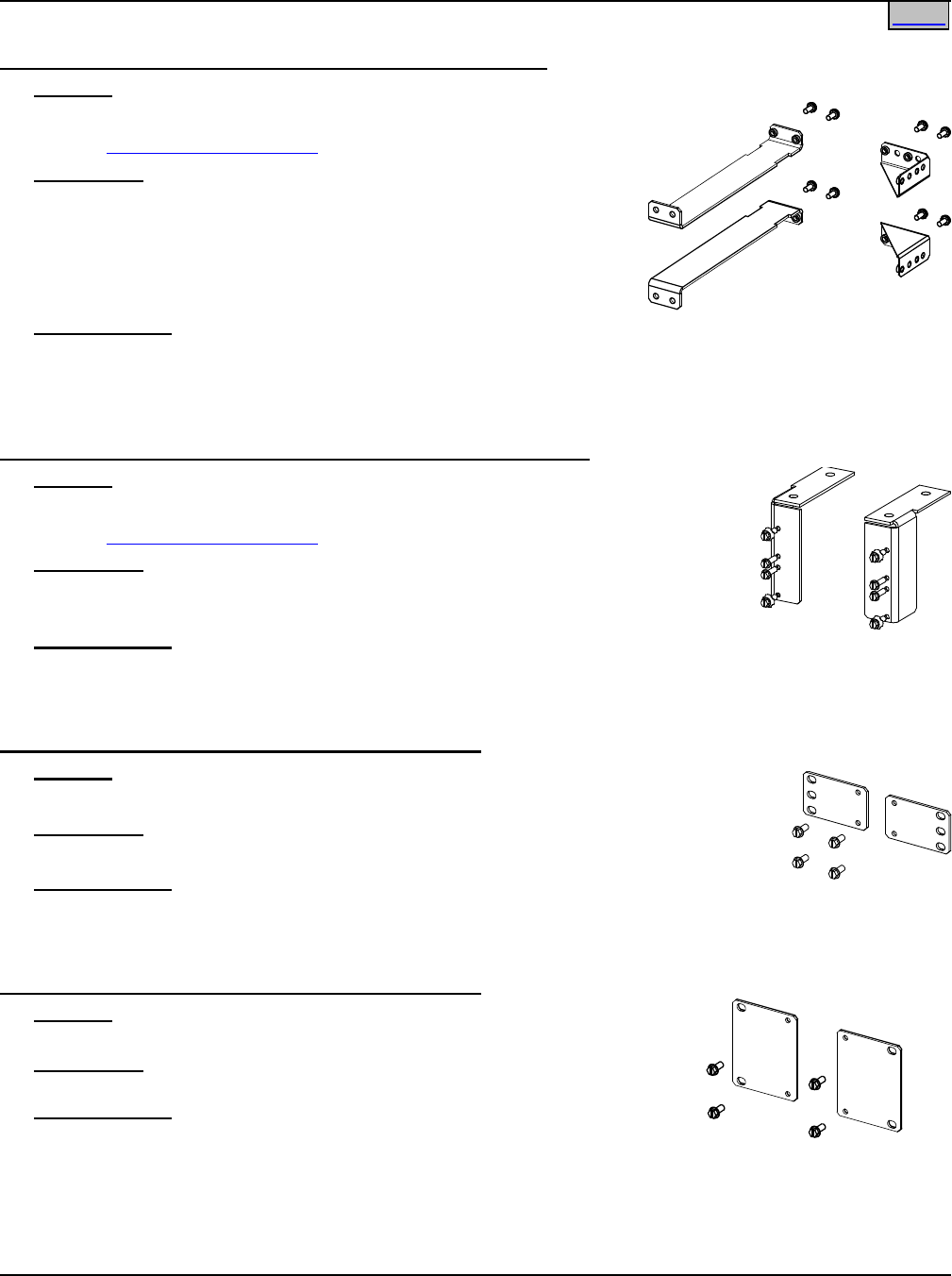
SAG582136600 System Application Guide
Issue AU, February 21, 2014 Spec. No. 582136600 (Model 211NGFB)
Page 42 of 105
This document is property of Emerson Network Power, Energy Systems, North America, Inc. and contains confidential and proprietary information owned by Emerson Network Power, Energy
Systems, North America, Inc. Any copying, use, or disclosure of it without the written permission of Emerson Network Power, Energy Systems, North America, Inc. is strictly prohibited.
Home
Mounting and Adapter Kits
Optional Wall Mount Bracket Kit for Lists 1 and 2, P/N 541285
Features
♦ Allows for horizontal or vertical wall mounting.
♦ See Physical Size Information for mounting dimensions.
Restrictions
For use with List 1 or 2 only.
Customer must supply mounting fasteners for securing the Wall Mount
Bracket to the wall.
This Kit will not support wall-mounting when the 58213660001 and
58213660002 shelves are flush mounted.
Ordering Notes
1) Order P/N 541285, which consists of two (2) P/N 545701 horizontal wall mounting brackets and two (2)
P/N 541284 vertical wall mounting brackets, and eight (8) 12-24 x ½” screws for attaching the brackets to
the shelf.
Optional Wall Mount Bracket Kit for Lists 1, 2, 5 and 6, P/N 553203
Features
♦ Allows for vertical wall mounting.
♦ See Physical Size Information for mounting dimensions.
Restrictions
Customer must supply mounting fasteners for securing the Wall Mount Brackets to
the wall.
Ordering Notes
1) Order P/N 553203, which consists of two (2) wall brackets (P/N 553058 and 553059) and eight (8) 12-24
x ¾” screws with four (4) ground washers for attaching the brackets to the shelf.
Optional 19” to 23” 1RU Rack Adapter Kit, P/N 540993
Features
♦ Allows for 23” 1RU relay rack mounting
Restrictions
For use with List 1 only.
Ordering Notes
1) Order P/N 540993, which consists of two (2) P/N 540994 adapters and four (4) 12-24 x 1/”2 thread
forming screws.
Optional 19” to 23” 2RU Rack Adapter Kit, P/N 545728
Features
♦ Allows for 23” 2RU relay rack mounting
Restrictions
For use with List 5 only.
Ordering Notes
1) Order P/N 545728, which consists of two (2) P/N 545727 adapters and
four (4) 12-24 x 1/”2 thread forming screws.
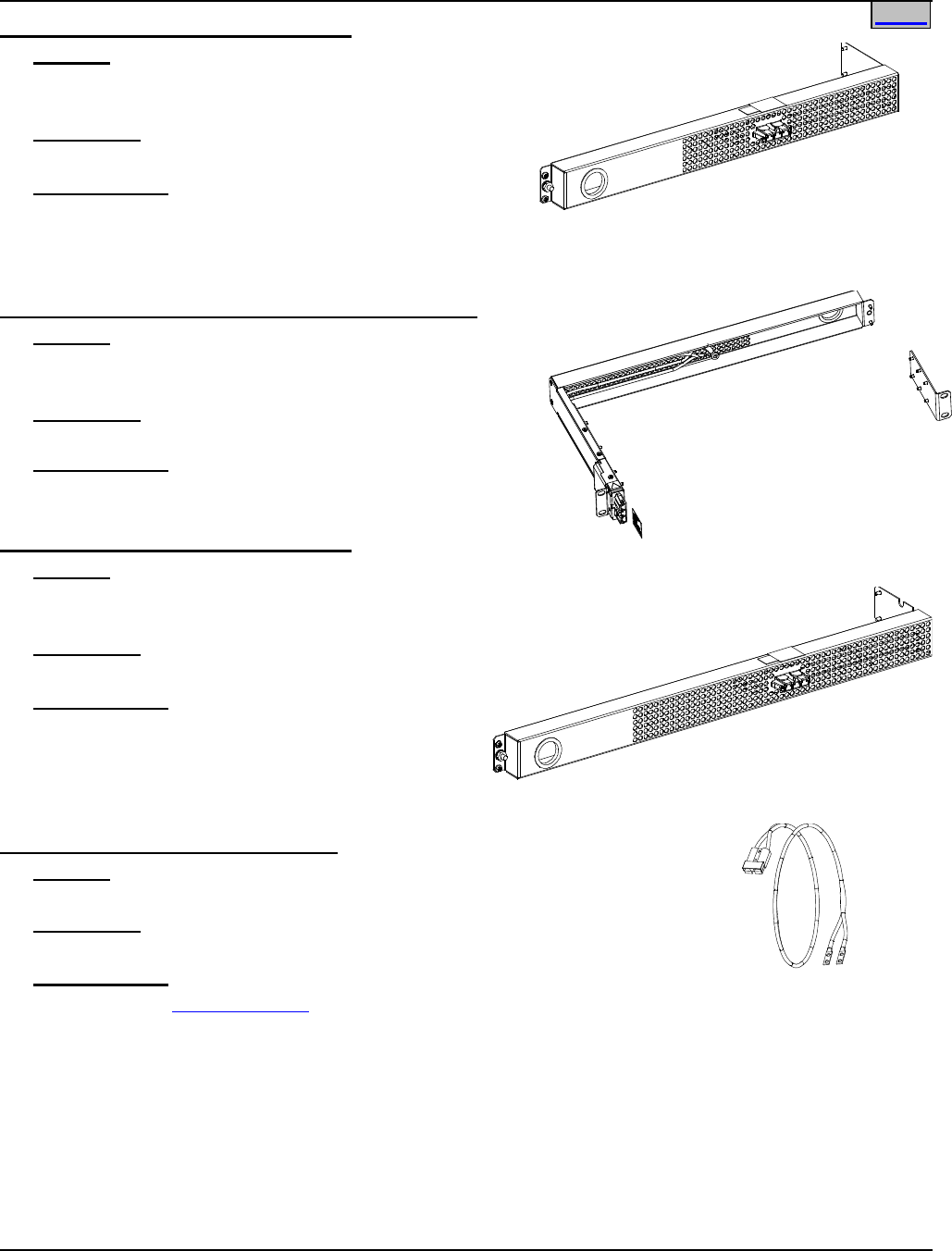
System Application Guide SAG582136600
Spec. No. 582136600 (Model 211NGFB) Issue AU, February 21, 2014
Page 43 of 105
This document is property of Emerson Network Power, Energy Systems, North America, Inc. and contains confidential and proprietary information owned by Emerson Network Power, Energy
Systems, North America, Inc. Any copying, use, or disclosure of it without the written permission of Emerson Network Power, Energy Systems, North America, Inc. is strictly prohibited.
Optional 19” Rear Cover Kit, P/N 555260
Features
♦ Allows for 19” 1RU flush rack mount configuration
♦ AC input unit is moved to the rear panel
Restrictions
For use with List 1 only.
Ordering Notes
1) Order P/N 555260, which consists of one (1) P/N
553271 19” rear cover assembly, one (1) P/N 29041838 caution label and one (1) P/N PSK04118562 AC
input jumper.
Optional 3” Projection Mount Kit for List 1, P/N 556828
Features
♦ Allows for 19" 1RU 3" projection rack mount
configuration
Restrictions
For use with List 1 only.
Ordering Notes
1) Order by P/N 556828 as required.
Optional 23” Rear Cover Kit, P/N 555261
Features
♦ Allows for 23” 1RU flush rack mount configuration
♦ AC input unit is moved to the rear panel
Restrictions
For use with List 2 only.
Ordering Notes
1) Order P/N 555261, which consists of one (1) P/N
555113 23” rear cover assembly, one (1) P/N
29041838 caution label and one (1) P/N
PSK04118555 AC input jumper.
Rear Battery Cable Exit Kit P/N 547645
Features
♦ Provides 12” battery cables exiting rear of shelf
Restrictions
For use with List 5 only.
Ordering Notes
1) For use with Battery Cabinets only.
Home
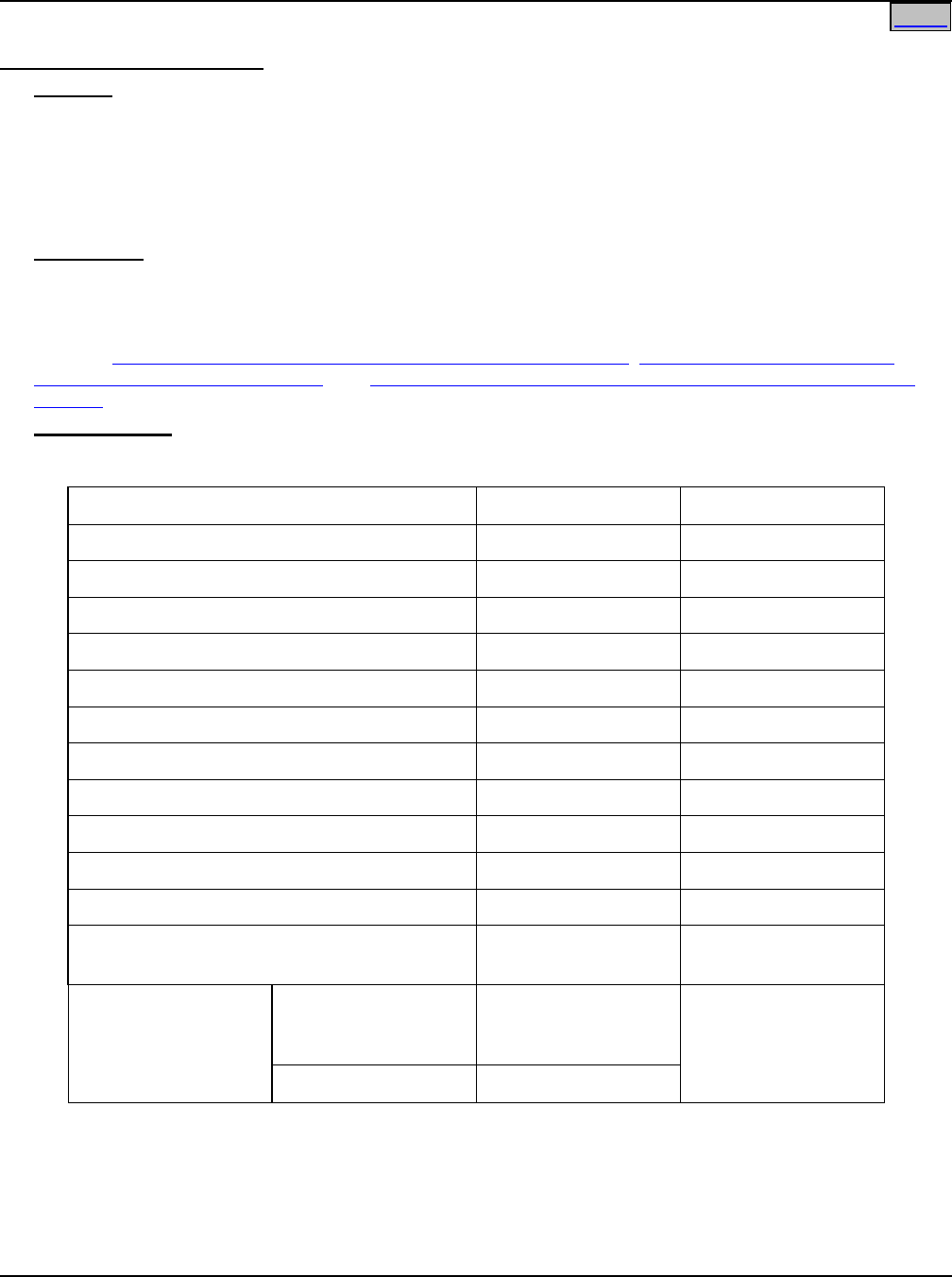
SAG582136600 System Application Guide
Issue AU, February 21, 2014 Spec. No. 582136600 (Model 211NGFB)
Page 44 of 105
This document is property of Emerson Network Power, Energy Systems, North America, Inc. and contains confidential and proprietary information owned by Emerson Network Power, Energy
Systems, North America, Inc. Any copying, use, or disclosure of it without the written permission of Emerson Network Power, Energy Systems, North America, Inc. is strictly prohibited.
Home
Distribution Devices
GMT Load Distribution Fuses
Features
♦ Each List BF, LF, NF Distribution Unit holds up to five (5) 0-15A GMT load distribution fuses and eight (8)
0-10A GMT load distribution fuses.
♦ Each List BC, LC, NC, BA, LA, NA Distribution Unit holds up to five (5) 0-10A GMT load distribution fuses.
♦ Each List BG and NG Distribution Unit holds up to ten (10) 0-15A GMT load distribution fuses.
♦ Each List KG Distribution Panel holds up to twenty (20) 0-15A GMT load distribution fuses.
Restrictions
When used for power distribution, load should not exceed 80% of device rating, except 10 and 15 ampere
fuses, for which load should not exceed 70% of device rating.
See also the Restrictions for each Distribution Unit in the LIST DESCRIPTIONS section.
See also Load Distribution Wiring (GMT Fuses) (Lists BG and NG only), Load Distribution Wiring (GMT
Fuses) (Lists BF, LF, and NF only), and Load Distribution Wiring (GMT Fuses) (Lists BC, LC, NC, BA, LA,
and NA) under WIRING NOTES for additional wiring restrictions.
Ordering Notes
1) Order GMT fuses per Table 2.
Ampere Rating
P/N
Fuse Color
18/100 GMT-A
248610301
--
1/4
248610200
Violet
1/2
248610300
Red
3/4
248610500
Brown
1-1/3
248610700
White
2
248610800
Orange
3
248610900
Blue
5
248611000
Green
7-1/2
248611300
Black-White
10
248611200
Red-White
15
248611500
Red-Blue
Replacement
Dummy Fuse
248872600 ---
Replacement Safety
Fuse Cover
Lists BF, LF, NF,
BC, LC, NC,
BA, LA, NA and KG
102774
--
Lists BG and NG
248898700
Table 2
GMT Fuses

System Application Guide SAG582136600
Spec. No. 582136600 (Model 211NGFB) Issue AU, February 21, 2014
Page 45 of 105
This document is property of Emerson Network Power, Energy Systems, North America, Inc. and contains confidential and proprietary information owned by Emerson Network Power, Energy
Systems, North America, Inc. Any copying, use, or disclosure of it without the written permission of Emerson Network Power, Energy Systems, North America, Inc. is strictly prohibited.
Home
Bullet Nose-Type Circuit Breakers
Features
♦ Each List BC, LC, and NC Distribution Unit holds up to four (4) bullet nose-type load distribution circuit
breakers.
♦ Each List BA, LA, and NA Distribution Unit holds up to two (2) bullet nose-type battery disconnect circuit
breakers and up to two (2) bullet nose-type load distribution circuit breakers.
Restrictions
See also the Restrictions for each Distribution Unit in the LIST DESCRIPTIONS section.
See also Load Distribution Wiring (Circuit Breakers) (Lists BC, LC, NC, BA, LA, and NA) and Input Battery
Wiring (to Battery Disconnect Circuit Breakers) (Lists BA, LA, and NA) under WIRING NOTES for additional
wiring restrictions.
Ordering Notes
1) Order circuit breakers per Table 3.
Ampere
Rating
P/N
Electrical Trip1
(White Handle)
Electrical/
Mechanical Trip2
(Black Handle)
1
102272
101596
3
102273
101597
5
102274
101598
10
102275
101599
15
102276
101600
20
102277
101601
25
102278
101602
30
102279
101603
35
102280
101604
40
102281
101605
45
121998
121997
50
102282
101606
60
102283
101607
70
102284
101608
75
102285
101609
80
121996
121995
90
138887
138888
100
102286
101610
See Table 6 for recommended wire sizes and lugs.
Circuit Breaker Alarm Operation:
1 Provides an alarm during an electrical trip condition only.
2 Provides an alarm during an electrical or manual trip condition.
Note that Electrical Trip only circuit breakers are not typically used for battery
disconnect circuit breakers.
Table 3
Bullet Nose-Type Circuit Breakers
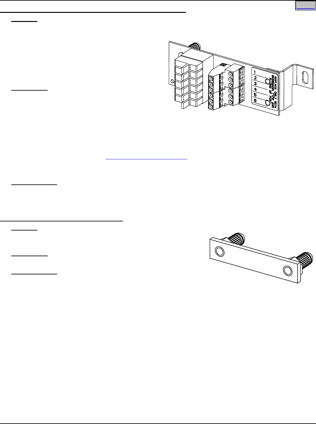
SAG582136600 System Application Guide
Issue AU, February 21, 2014 Spec. No. 582136600 (Model 211NGFB)
Page 46 of 105
This document is property of Emerson Network Power, Energy Systems, North America, Inc. and contains confidential and proprietary information owned by Emerson Network Power, Energy
Systems, North America, Inc. Any copying, use, or disclosure of it without the written permission of Emerson Network Power, Energy Systems, North America, Inc. is strictly prohibited.
Home
Optional Bullet Nose 6-Position GMT Fuse Module, P/N 545332
Features
♦ Factory installed in a List BC, LC, NC, BA, LA, and NA Distribution Unit.
♦ Provides six (6) 0A to 15A GMT fuse load
distribution positions.
♦ Screw clamp type load and load return terminals
provided.
♦ Includes six (6) dummy fuses equipped with
safety fuse covers.
Restrictions
For use with Lists BC, LC, NC, BA, LA, and NA.
Terminal block wire size capacity: 24 to 14 AWG.
Requires two (2) bullet device mounting positions.
Fuse Module has a 30A @ +40°C (+104°F) and +65°C (+149°F) maximum capacity. Maximum GMT fuse
size is 15A. Fuses are to be loaded from bottom to top with highest value in the lowest position.
Caution: A fuse with a rating greater than 10 amperes SHALL HAVE an empty mounting position
between it and any other overcurrent protective device.
See also the Restrictions under “GMT Load Distribution Fuses” in the ACCESSORY DESCRIPTIONS
section.
Factory installed only.
Ordering Notes
1) Order optional Bullet Nose-Type 6-Position GMT Fuse Module (P/N 545332) as required.
2) Order GMT fuses as required per Table 2.
Optional Bulk Output Busbar, P/N 535015
Features
♦ Each Bulk Output Busbar installs in a single circuit breaker
position in a List BC, LC, NC, BA, LA, and NA Distribution Unit.
Restrictions
For use with Lists BC, LC, NC, BA, LA, and NA.
Ordering Notes
1) Order by P/N 535015 as required.
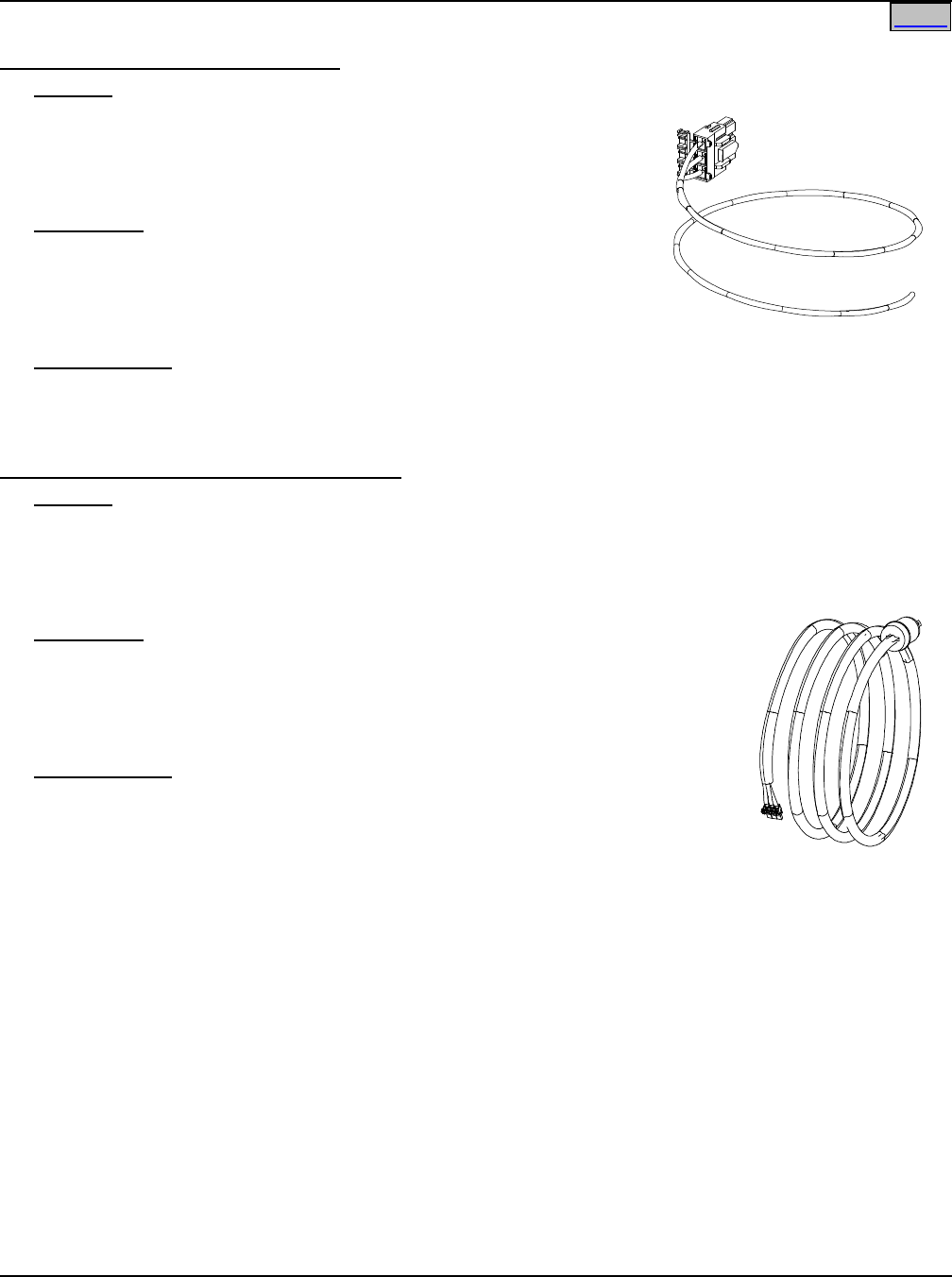
System Application Guide SAG582136600
Spec. No. 582136600 (Model 211NGFB) Issue AU, February 21, 2014
Page 47 of 105
This document is property of Emerson Network Power, Energy Systems, North America, Inc. and contains confidential and proprietary information owned by Emerson Network Power, Energy
Systems, North America, Inc. Any copying, use, or disclosure of it without the written permission of Emerson Network Power, Energy Systems, North America, Inc. is strictly prohibited.
Home
AC Input Cables and Line Cords
AC Input Cable Assembly, P/N 535232
Features
♦ Provides one (1) 30” long, 8 AWG, AC Input Cable Assembly;
♦ terminated on one end with a Molex plug which mates with AC
input receptacle on the Power/Distribution Shelf,
♦ and the remaining end un-terminated.
Restrictions
Rated for 30A.
For use with List 1, 2, 5, and 6.
Each List 1 and 2 requires one (1) AC Input Cable Assembly/Line Cord.
Each List 5 and 6 requires two (2) AC Input Cable Assemblies/Line Cords.
Ordering Notes
1) Order one (1) AC Input Cable Assembly/Line Cord as required for each List 1 and 2 ordered.
2) Order two (2) AC Input Cable Assemblies/Line Cords as required for each List 5 and 6 ordered.
AC Input Line Cord, 208/240VAC, P/N 540946
Features
♦ Provides one (1) 14’ long, 8 AWG, AC Input Line Cord;
♦ terminated on one end with a Molex plug which mates with AC input receptacle on the
Power/Distribution Shelf,
♦ and on the remaining end with a NEMA L6-30P twist-lock plug.
Restrictions
For 208/240 VAC only (rated for 30A at 208/240VAC).
For use with List 1, 2, 5, and 6.
Each List 1 and 2 requires one (1) AC Input Cable Assembly/Line Cord.
Each List 5 and 6 requires two (2) AC Input Cable Assemblies/Line Cords.
Ordering Notes
1) Order one (1) AC Input Cable Assembly/Line Cord as required for each List 1
and 2 ordered.
2) Order two (2) AC Input Cable Assemblies/Line Cords as required for each List 5
and 6 ordered.
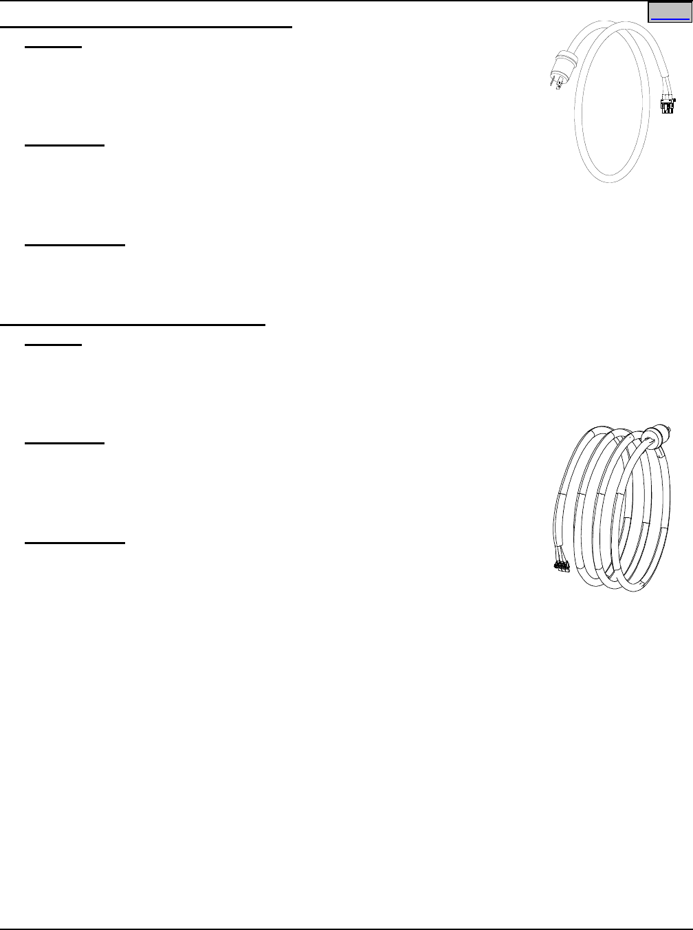
SAG582136600 System Application Guide
Issue AU, February 21, 2014 Spec. No. 582136600 (Model 211NGFB)
Page 48 of 105
This document is property of Emerson Network Power, Energy Systems, North America, Inc. and contains confidential and proprietary information owned by Emerson Network Power, Energy
Systems, North America, Inc. Any copying, use, or disclosure of it without the written permission of Emerson Network Power, Energy Systems, North America, Inc. is strictly prohibited.
Home
AC Input Line Cord, 208/240VAC, P/N 545616
Features
♦ Provides one (1) 6’ long, 8 AWG, AC Input Line Cord;
♦ terminated on one end with a Molex plug which mates with AC input
receptacle on the Power/Distribution Shelf,
♦ and on the remaining end with a NEMA L6-30P twist-lock plug.
Restrictions
For 208/240 VAC only (rated for 30A at 208/240VAC).
For use with List 1, 2, 5, and 6.
Each List 1 and 2 requires one (1) AC Input Cable Assembly/Line Cord.
Each List 5 and 6 requires two (2) AC Input Cable Assemblies/Line Cords.
Ordering Notes
1) Order one (1) AC Input Cable Assembly/Line Cord as required for each List 1 and 2 ordered.
2) Order two (2) AC Input Cable Assemblies/Line Cords as required for each List 5 and 6 ordered.
AC Input Line Cord, 120VAC, P/N 545252
Features
♦ Provides one (1) 14’ long, 8 AWG, AC Input Line Cord;
♦ terminated on one end with a Molex plug which mates with AC input receptacle on the
Power/Distribution Shelf,
♦ and on the remaining end with a NEMA L5-30P twist-lock plug.
Restrictions
For 120 VAC only (rated for 30A at 120VAC).
For use with List 1, 2, 5, and 6.
Each List 1 and 2 requires one (1) AC Input Cable Assembly/Line Cord.
Each List 5 and 6 requires two (2) AC Input Cable Assemblies/Line Cords.
Ordering Notes
1) Order one (1) AC Input Cable Assembly/Line Cord as required for each List 1
and 2 ordered.
2) Order two (2) AC Input Cable Assemblies/Line Cords as required for each List 5
and 6 ordered.
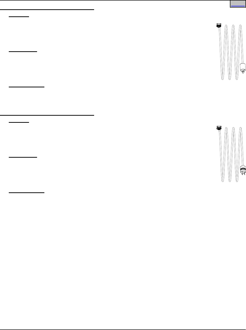
System Application Guide SAG582136600
Spec. No. 582136600 (Model 211NGFB) Issue AU, February 21, 2014
Page 49 of 105
This document is property of Emerson Network Power, Energy Systems, North America, Inc. and contains confidential and proprietary information owned by Emerson Network Power, Energy
Systems, North America, Inc. Any copying, use, or disclosure of it without the written permission of Emerson Network Power, Energy Systems, North America, Inc. is strictly prohibited.
Home
AC Input Line Cord, 120VAC, P/N 545478
Features
♦ Provides one (1) 14’ long, 14/3 AWG, AC Input Line Cord;
♦ terminated on one end with a Molex plug which mates with AC input receptacle on
the Power/Distribution Shelf,
♦ and on the remaining end with a NEMA 5-15P plug.
Restrictions
For 120 VAC only (rated for 15A at 120VAC).
For use with List 1 and 5 equipped with R48-500 Rectifier Modules.
Each List 1 requires one (1) AC Input Cable Assembly/Line Cord.
Each List 5 requires two (2) AC Input Cable Assemblies/Line Cords.
Ordering Notes
1) Order one (1) AC Input Cable Assembly/Line Cord as required for each List 1 ordered.
2) Order two (2) AC Input Cable Assemblies/Line Cords as required for each List 5 ordered.
AC Input Line Cord, 120VAC, P/N 545479
Features
♦ Provides one (1) 14’ long, 14/3 AWG, AC Input Line Cord;
♦ terminated on one end with a Molex plug which mates with AC input receptacle on
the Power/Distribution Shelf,
♦ and on the remaining end with a NEMA L5-15P twist-lock plug.
Restrictions
For 120 VAC only (rated for 15A at 120VAC).
For use with List 1 and 5 equipped with R48-500 Rectifier Modules.
Each List 1 requires one (1) AC Input Cable Assembly/Line Cord.
Each List 5 requires two (2) AC Input Cable Assemblies/Line Cords.
Ordering Notes
1) Order one (1) AC Input Cable Assembly/Line Cord as required for each List 1 ordered.
2) Order two (2) AC Input Cable Assemblies/Line Cords as required for each List 5 ordered.
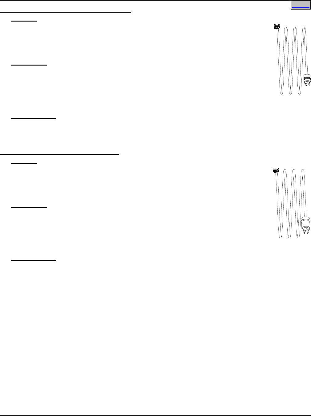
SAG582136600 System Application Guide
Issue AU, February 21, 2014 Spec. No. 582136600 (Model 211NGFB)
Page 50 of 105
This document is property of Emerson Network Power, Energy Systems, North America, Inc. and contains confidential and proprietary information owned by Emerson Network Power, Energy
Systems, North America, Inc. Any copying, use, or disclosure of it without the written permission of Emerson Network Power, Energy Systems, North America, Inc. is strictly prohibited.
Home
AC Input Line Cord, 208/240VAC, P/N 545480
Features
♦ Provides one (1) 14’ long, 14/3 AWG, AC Input Line Cord;
♦ terminated on one end with a Molex plug which mates with AC input receptacle on
the Power/Distribution Shelf,
♦ and on the remaining end with a NEMA L6-15P twist-lock plug.
Restrictions
For 240 VAC only (rated for 15A at 208/240VAC).
For use with List 1 and 5.
For use with List 2 and 6 with R48-500 Rectifiers.
Each List 1 and 2 requires one (1) AC Input Cable Assembly/Line Cord.
Each List 5 and 6 requires two (2) AC Input Cable Assemblies/Line Cords.
Ordering Notes
1) Order one (1) AC Input Cable Assembly/Line Cord as required for each List 1 ordered.
2) Order two (2) AC Input Cable Assemblies/Line Cords as required for each List 5 ordered.
AC Input Line Cord, 120VAC, P/N 545481
Features
♦ Provides one (1) 14’ long, 12/3 AWG, AC Input Line Cord;
♦ terminated on one end with a Molex plug which mates with AC input receptacle on
the Power/Distribution Shelf,
♦ and on the remaining end with a NEMA L5-20P twist-lock plug.
Restrictions
For 120 VAC only (rated for 20A at 120VAC).
For use with List 1 and 5.
For use with List 2 and 6 with R48-500 Rectifiers.
Each List 1 and 2 requires one (1) AC Input Cable Assembly/Line Cord.
Each List 5 and 6 requires two (2) AC Input Cable Assemblies/Line Cords.
Ordering Notes
1) Order one (1) AC Input Cable Assembly/Line Cord as required for each List 1 ordered.
2) Order two (2) AC Input Cable Assemblies/Line Cords as required for each List 5 ordered.
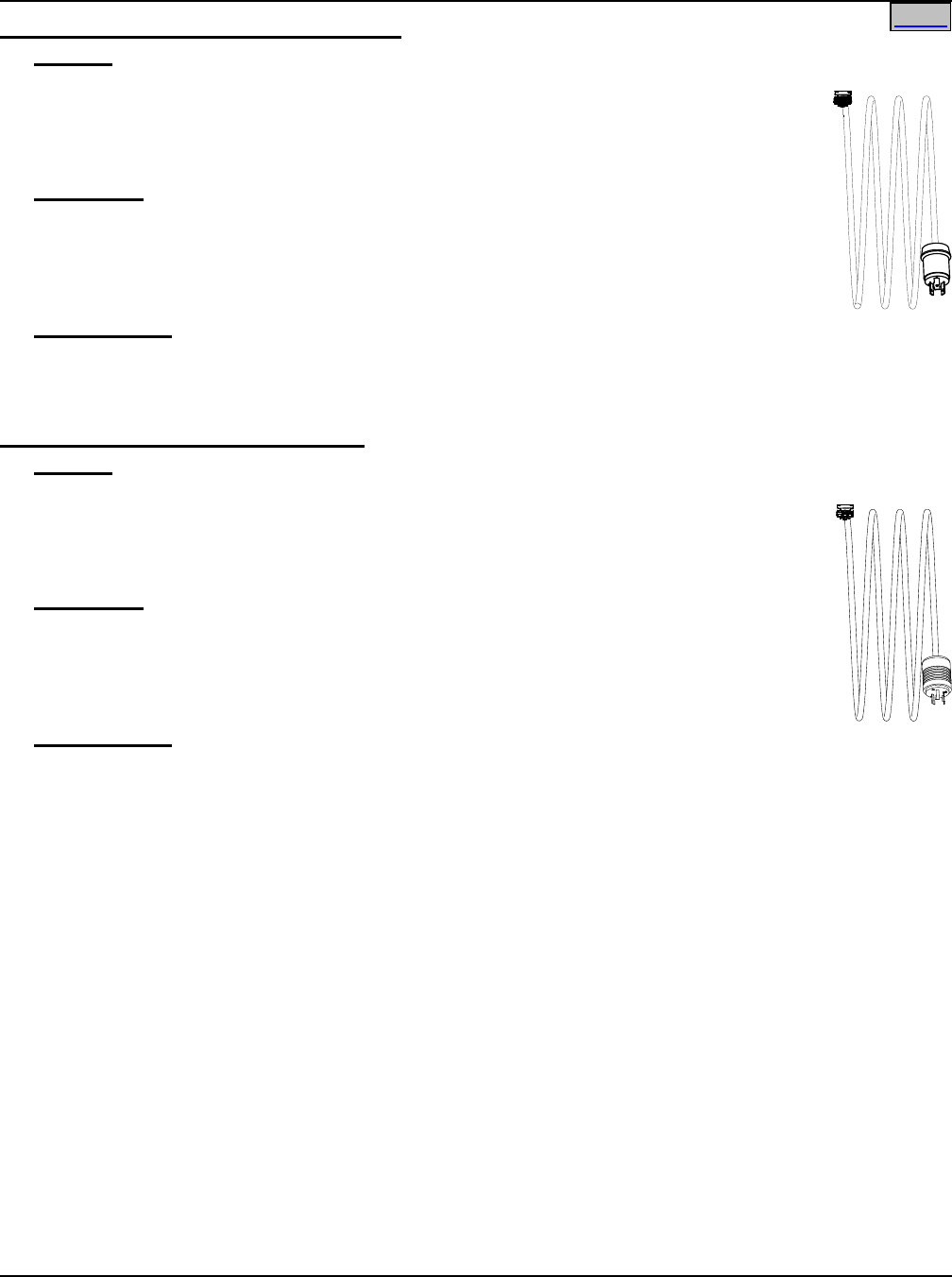
System Application Guide SAG582136600
Spec. No. 582136600 (Model 211NGFB) Issue AU, February 21, 2014
Page 51 of 105
This document is property of Emerson Network Power, Energy Systems, North America, Inc. and contains confidential and proprietary information owned by Emerson Network Power, Energy
Systems, North America, Inc. Any copying, use, or disclosure of it without the written permission of Emerson Network Power, Energy Systems, North America, Inc. is strictly prohibited.
Home
AC Input Line Cord, 208/240VAC, P/N 545553
Features
♦ Provides one (1) 14’ long, 12/3 AWG, AC Input Line Cord;
♦ terminated on one end with a Molex plug which mates with AC input receptacle on
the Power/Distribution Shelf,
♦ and on the remaining end with a NEMA L6-20P twist-lock plug.
Restrictions
For 240 VAC only (rated for 20A at 208/240VAC).
For use with List 1, 2, 5, and 6.
Each List 1 and 2 requires one (1) AC Input Cable Assembly/Line Cord.
Each List 5 and 6 requires two (2) AC Input Cable Assemblies/Line Cords.
Ordering Notes
1) Order one (1) AC Input Cable Assembly/Line Cord as required for each List 1 and 2 ordered.
2) Order two (2) AC Input Cable Assemblies/Line Cords as required for each List 5 and 6 ordered.
AC Input Line Cord, 120VAC, P/N 547525
Features
♦ Provides one (1) 14’ long, 12/3 AWG, AC Input Line Cord;
♦ terminated on one end with a Molex plug which mates with AC input receptacle on
the Power/Distribution Shelf,
♦ and on the remaining end with a NEMA L5-30P twist-lock plug.
Restrictions
For 120 VAC only (rated for 30A at 120VAC).
For use with List 1, 2, 5, and 6.
Each List 1 and 2 requires one (1) AC Input Cable Assembly/Line Cord.
Each List 5 and 6 requires two (2) AC Input Cable Assemblies/Line Cords.
Ordering Notes
1) Order one (1) AC Input Cable Assembly/Line Cord as required for each List 1 and 2 ordered.
2) Order two (2) AC Input Cable Assemblies/Line Cords as required for each List 5 and 6 ordered.
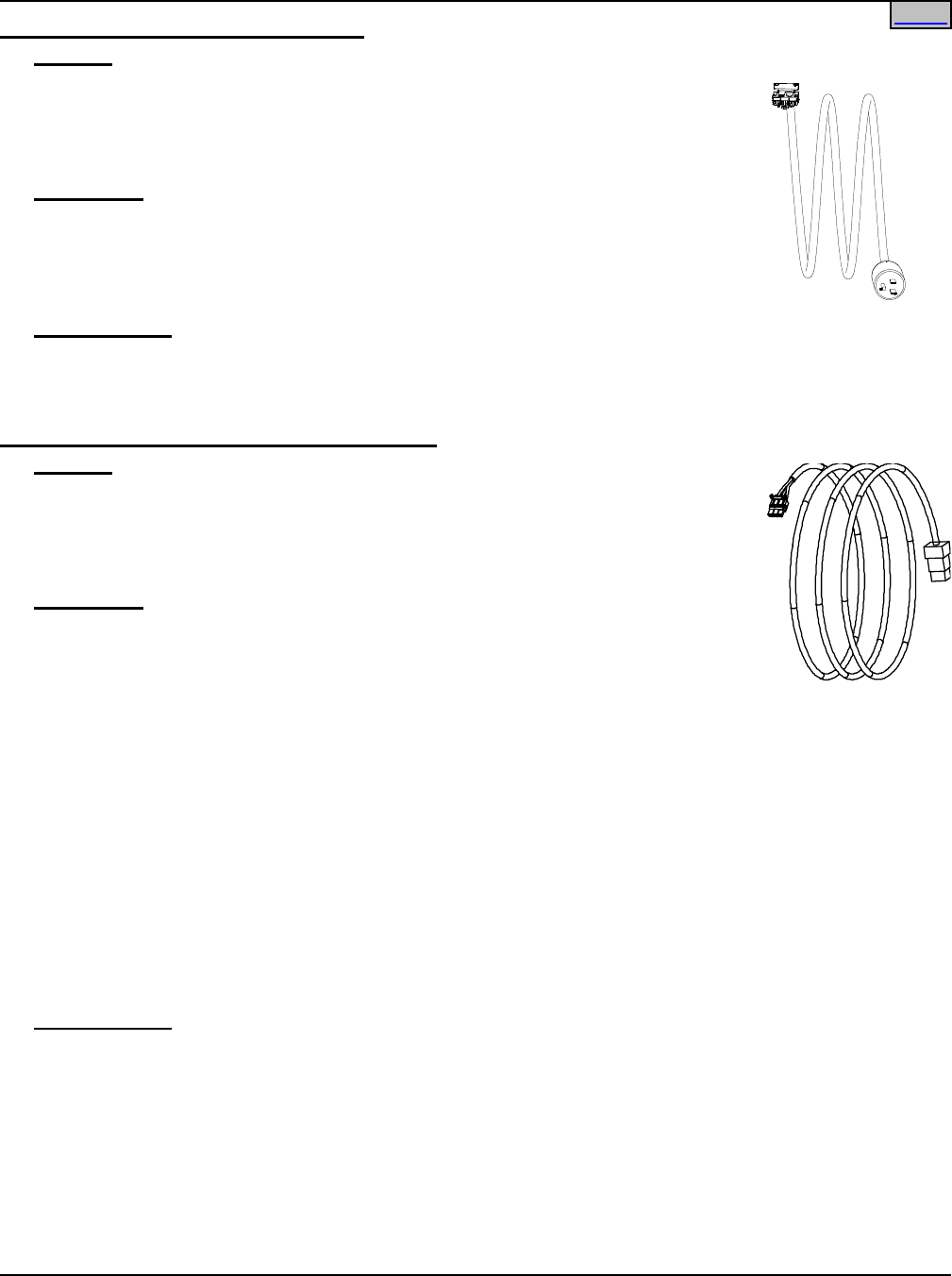
SAG582136600 System Application Guide
Issue AU, February 21, 2014 Spec. No. 582136600 (Model 211NGFB)
Page 52 of 105
This document is property of Emerson Network Power, Energy Systems, North America, Inc. and contains confidential and proprietary information owned by Emerson Network Power, Energy
Systems, North America, Inc. Any copying, use, or disclosure of it without the written permission of Emerson Network Power, Energy Systems, North America, Inc. is strictly prohibited.
Home Home
AC Input Line Cord, 120VAC, P/N 548457
Features
♦ Provides one (1) 6’ long, 14/3 AWG, AC Input Line Cord;
♦ terminated on one end with a Molex plug which mates with AC input
receptacle on the Power/Distribution Shelf,
♦ and on the remaining end with a NEMA 5-15P plug.
Restrictions
For 120 VAC only (rated for 15A at 120VAC).
For use with List 1 and 5 with R48-500 Rectifiers.
Each List 1 requires one (1) AC Input Cable Assembly/Line Cord.
Each List 5 requires two (2) AC Input Cable Assemblies/Line Cords.
Ordering Notes
1) Order one (1) AC Input Cable Assembly/Line Cord as required for each List 1 ordered.
2) Order two (2) AC Input Cable Assemblies/Line Cords as required for each List 5 ordered.
AC Input Line Cord, 120/208/240VAC, P/N 548196
Features
♦ Provides one (1) 6’ long, 12/3 AWG, AC Input Line Cord;
♦ terminated on one end with a Molex plug which mates with AC input
receptacle on the Power/Distribution Shelf,
♦ and on the remaining end with an IEC320 C20 plug.
Restrictions
For 120/208/240 VAC (rated for 20A at 120/208/240VAC).
For 208/240V use with List 1, 2, 5, and 6 and all Rectifier Modules.
For 120V use with List 1 and 5 and all Rectifier Modules.
For 120V use with List 2 and 6 with 500W Rectifier Module only.
Each List 1 and 2 requires one (1) AC Input Cable Assembly/Line Cord.
Each List 5 and 6 requires two (2) AC Input Cable Assemblies/Line Cords.
Per UL 60950-1, 2nd Edition, when this cord is used with this power system, the following restrictions apply:
• The power system must be used “in a location having equipotential bonding (such as a
telecommunications centre, a dedicated computer room or a restricted access location).
• “The building installation shall provide a means for connection to protective earth; and
• “The equipment is to be connected to that means; and
• “A service person shall check whether or not the socket-outlet from which the equipment is to be powered
provides a connection to the building protective earth. If not, the service person shall arrange for the
installation of a protective earthing conductor from the separated protective earthing terminal to the
protective earth wire in the building.”
Ordering Notes
1) Order one (1) AC Input Cable Assembly/Line Cord as required for each List 1 and 2 ordered.
2) Order two (2) AC Input Cable Assemblies/Line Cords as required for each List 5 and 6 ordered.
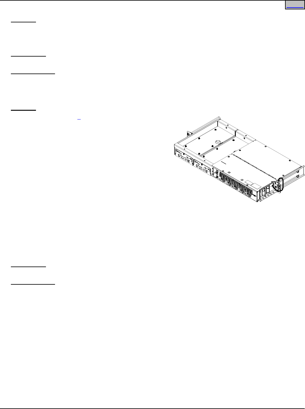
System Application Guide SAG582136600
Spec. No. 582136600 (Model 211NGFB) Issue AU, February 21, 2014
Page 53 of 105
This document is property of Emerson Network Power, Energy Systems, North America, Inc. and contains confidential and proprietary information owned by Emerson Network Power, Energy
Systems, North America, Inc. Any copying, use, or disclosure of it without the written permission of Emerson Network Power, Energy Systems, North America, Inc. is strictly prohibited.
Special Application Digital Input Cable Kit, P/N 554935
Features
♦ Provides an alarm cable kit to add -48VDC to digital input #2.
♦ The kit consists of two pieces that plug together to make a complete connection. One part is pre-wired to
the shelf and the other part is shipped loose.
Restrictions
For use with List 1 and 2.
Ordering Notes
1) Order one (1) Special Application Digital Input Cable Kit as required for each List 1 and 2 ordered.
AP6C57EA/EB Ring & Distribution Module
Features
♦ When used with List 6, this module is designed to
supply a filtered and regulated –48 VDC source and a
continuous 20 Hz ringing supply source to imbedded
subscriber loop carrier telecommunication systems
(such as SLC-96 or SLC Series-5) requiring up to 45
A of load capacity.
♦ Designed to mount in a 23” relay rack, the module is
one rack unit high, with 5” front projection.
♦ Includes two (2) 50VA ringers with automatic transfer
capability (N+1 redundancy).
♦ Provides 35 DC distribution fuse positions, configured
in five groups of seven, feeding five channel banks.
Includes 35 dummy fuses.
♦ Connectorized cables are available for SLC-96 or SLC Series-5 applications. Required DC distribution
fuses are included with each cable assembly ordered.
♦ An Order Wire Option provides a connection interface for an analog communication link over a metallic
pair, with surge protection.
♦ See Ring & Distribution Module Installation and User Manuals (IM6C57E and UM6C57E) for complete
specifications.
Restrictions
Cannot be used with Distribution units List BF, LF, or NF.
Ordering Notes
1) For a Ring & Distribution Module equipped with two (2) 50VA ringers only, order AP6C57EA (A7000626).
2) For a Ring & Distribution Module equipped with two (2) 50VA ringers and the Order Wire option, order
AP6C57EB (A7000796).
3) Order distribution cable assemblies as required, from the following table. Order up to five (5) cable
assemblies (one per channel bank). Required fuses are included with each cable assembly. Cable
assemblies can be mixed.
Home
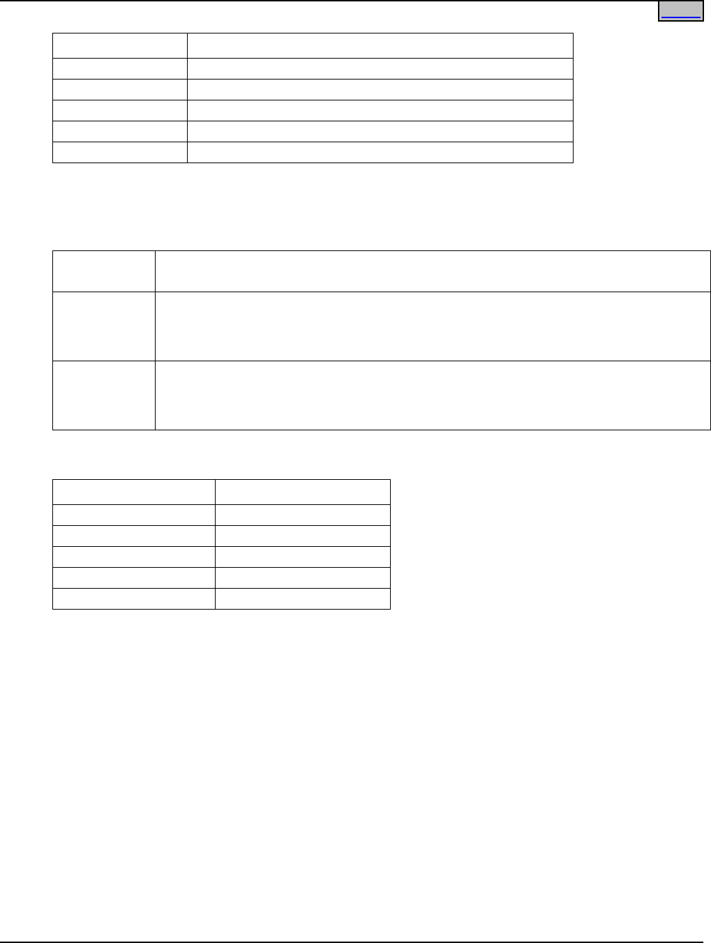
SAG582136600 System Application Guide
Issue AU, February 21, 2014 Spec. No. 582136600 (Model 211NGFB)
Page 54 of 105
This document is property of Emerson Network Power, Energy Systems, North America, Inc. and contains confidential and proprietary information owned by Emerson Network Power, Energy
Systems, North America, Inc. Any copying, use, or disclosure of it without the written permission of Emerson Network Power, Energy Systems, North America, Inc. is strictly prohibited.
ORDERING CODE DESCRIPTION
P7000858
Cable assy for one SLC96 channel bank (8 ft.)
P7001139 Cable assy for one SLC96 channel bank (20 ft.)
P7000859
Cable assy for one SLC5 channel bank (8 ft.)
P7001136
Cable assy for one SLC5 channel bank (20 ft.)
P7000937* Cable assy for one channel bank, generic applications (8 ft.)
*Note: Each channel bank position on the panel has a maximum capacity of 11A.
4) Order Part No. 547491 DC power cable kit, as required. Provides two (2) 9” long cables to connect
between a power shelf and the DC input terminals of one (1) Ring & Distribution Module.
5) For SLC-96 or SLC Series-5 applications, order battery cable kits as required, from the following table.
ORDERING
CODE
DESCRIPTION
547646
Battery cable kit for SLC96 legacy power shelf (Tyco Mate-N-Lock connectors) - for 2
battery strings, Up to 3 cable kits can be installed in the power shelf with Distribution
units BC, LC, and NC. Two cable kits can be installed in DU Lists BA, LA, and NA. (Use
a flat washer, not provided.)
547647
Battery cable for SLC5 legacy power shelf (Tyco Mate-N-Lock connectors) - for
2 battery strings, Up to 3 cable kits can be installed in the power shelf with Distribution
units BC, LC, and NC. Two cable kits can be installed in DU Lists BA, LA, and NA. (Use
a flat washer, not provided.)
6) Spare parts for the AP6C57EA/EB Ring & Distribution Module can be ordered as required from the
following table.
ORDERING CODE DESCRIPTION
A0885525 1.33A Alarm SAN-O Fuse
A0885530 3A Alarm SAN-O Fuse
A0885531 5A Alarm SAN-O Fuse
A0885532 10A Alarm SAN-O Fuse
A7000627 (AP8C55AA) 50VA Ring Generator
Home
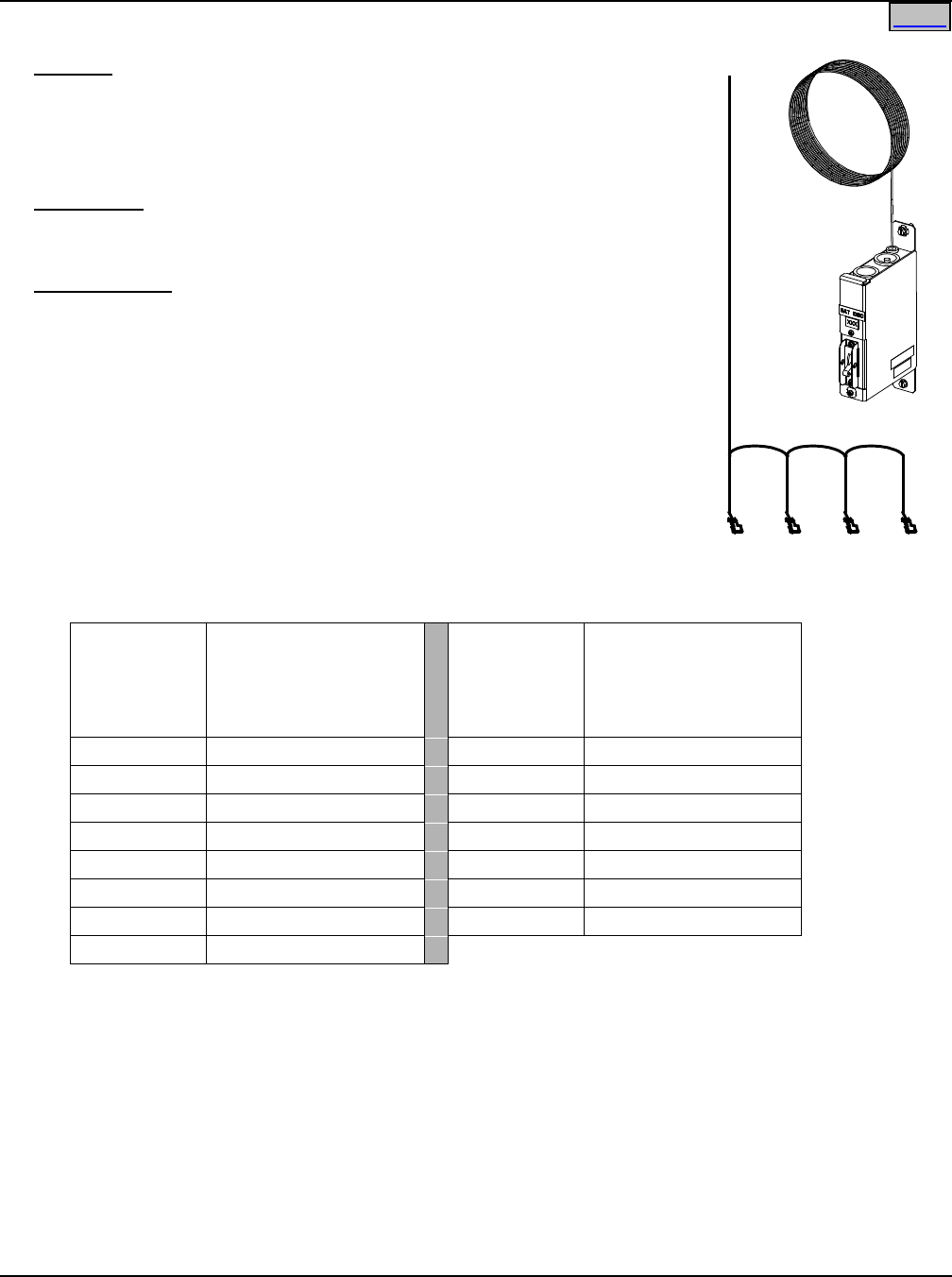
System Application Guide SAG582136600
Spec. No. 582136600 (Model 211NGFB) Issue AU, February 21, 2014
Page 55 of 105
This document is property of Emerson Network Power, Energy Systems, North America, Inc. and contains confidential and proprietary information owned by Emerson Network Power, Energy
Systems, North America, Inc. Any copying, use, or disclosure of it without the written permission of Emerson Network Power, Energy Systems, North America, Inc. is strictly prohibited.
Yellow Jumper/Alarm Lead (P/N 524384)
(for use when more than one Battery
Disconnect Units are ordered)
Home
External Battery Disconnect Unit, P/N 535282
Features
♦ Battery Disconnect Unit with mounting tabs.
♦ Two 1/4-20 studs w/hardware provided for installation of single hole
battery lugs.
♦ One (10’ long) alarm lead provided.
Restrictions
Circuit breakers are ordered separately.
Maximum number of Battery Disconnect Units per system is three (3).
Ordering Notes
1) Order by P/N 535282 as required.
2) Order a circuit breaker for each Battery Disconnect Unit from Table 4.
3) Also order the following lug kits for each battery disconnect circuit
breaker ordered: 545581(for use with 8 AWG wire and List 71), 540989
(for use with 10 AWG wire and List 72) or 555069 (for use with 6 AWG
wire and List 73) and 541031 (wire with lugs for connection from battery
disconnect to battery string).
4) Also order P/N 524384 Jumper/Alarm Lead if more than one (1) Battery
Disconnect Units are to be used (daisy-chains the alarm terminal of up
to three [3] Battery Disconnect Units). (Section of alarm lead between
Battery Disconnect Units is 30”, section of alarm lead between Battery
Disconnect Unit and system’s alarm terminal is 84”.)
Ampere
Rating
P/N
Electrical/Mechanical
Trip1
(Black Handle)
Ampere
Rating
P/N
Electrical/Mechanical
Trip1
(Black Handle)
1 256690300 35 256693500
3 256690700 40 256693900
5 256691100 50 256694300
10 256691500 60 256694700
15 256691900 70 256695100
20 256692300 75 256695500
25 256692700 100 256695900
30 256693100
Circuit Breaker Alarm Operation:
1
Provides an alarm during an electrical or manual trip condition.
Table 4
Battery Disconnect Unit Circuit Breakers
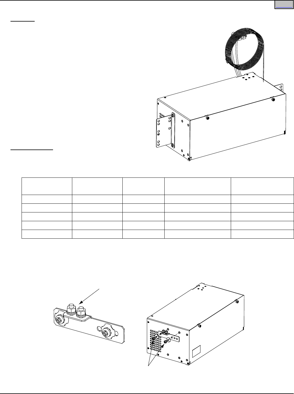
SAG582136600 System Application Guide
Issue AU, February 21, 2014 Spec. No. 582136600 (Model 211NGFB)
Page 56 of 105
This document is property of Emerson Network Power, Energy Systems, North America, Inc. and contains confidential and proprietary information owned by Emerson Network Power, Energy
Systems, North America, Inc. Any copying, use, or disclosure of it without the written permission of Emerson Network Power, Energy Systems, North America, Inc. is strictly prohibited.
NetSure™ 211BC Battery Cabinet (Spec. No. 541434)
Features
♦ The NetSure™ 211BC Battery Cabinet is rated at
30 amperes, and can be mounted in a 19” or 23”
nominal relay rack, or mounted to a suitable wall.
♦ The Battery Cabinet contains one (1) 40 ampere
battery disconnect circuit breaker.
♦ Battery circuit breaker alarm leads are provided
to tie into the power system’s alarm circuit.
♦ The Battery Cabinet is equipped with a battery
cable terminated in an Anderson connector.
♦ Cables to connect the batteries (as specified in
the table under Order Notes) into the Battery
Cabinet provided.
♦ Battery Cabinets can be paralleled to provide
greater reserve time. Battery cabinets contain a
second Anderson battery connector for plugging
one cabinet into another.
Ordering Notes
1) Order by Spec. No. 541434 as required.
2) Also order four (4) batteries per Battery Cabinet
per the following table.
Battery
Manufacturer
Manufacturer
P/N
Emerson
P/N
Capacity Amp-Hours
(8Hr rate)
Weight (lb)
per Battery
Hawker
SBS 15
139091
14
12.50
Fiamm
12SLA12
139092
12
12.35
EaglePicher
HE-12V7.7FR
139094
6.9
5.94
EaglePicher
HE-12V12.7FR
139093
11.6*
9.68
Enersys
NP18-12FR
139774
16 *
13.60
* 10Hr rate
3) When ordering 139774 batteries, also order 545427 Battery Connection kit.
4) When wall mounted, also order a battery cabinet frame grounding landing point adapter P/N 556872.
This adapter installs in the relay rack mounting bracket holes located on either side of the cabinet.
Frame Grounding Point
(1/4-20 Studs on 5/8” Centers)
Frame Ground Landing
Point Adapter P/N 556872
Attach Frame Ground Landing
Point Adapter to Cabinet
Home
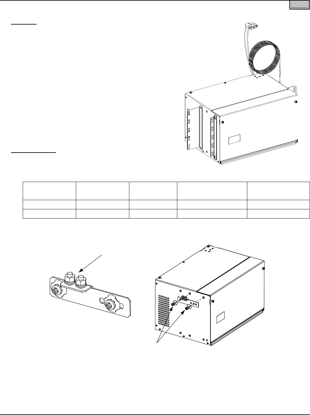
System Application Guide SAG582136600
Spec. No. 582136600 (Model 211NGFB) Issue AU, February 21, 2014
Page 57 of 105
This document is property of Emerson Network Power, Energy Systems, North America, Inc. and contains confidential and proprietary information owned by Emerson Network Power, Energy
Systems, North America, Inc. Any copying, use, or disclosure of it without the written permission of Emerson Network Power, Energy Systems, North America, Inc. is strictly prohibited.
NetSure™ 211BC Battery Cabinet (Spec. No. 545534)
Features
♦ The NetSure™ 211BC Battery Cabinet is rated at 30
amperes, and can be mounted in a 19” or 23” nominal
relay rack, or mounted to a suitable wall.
♦ The Battery Cabinet contains one (1) 40 ampere battery
disconnect circuit breaker.
♦ Battery circuit breaker alarm leads are provided to tie into
the power system’s alarm circuit.
♦ The Battery Cabinet is equipped with a battery cable
terminated in an Anderson connector.
♦ Cables to connect the batteries (as specified in the table
under Ordering Notes) into the Battery Cabinet provided.
♦ Battery Cabinets can be paralleled to provide greater
reserve time. Battery cabinets contain a second
Anderson battery connector for plugging one cabinet into
another.
Ordering Notes
1) Order by Spec. No. 545534 as required.
2) Also order four (4) batteries per Battery Cabinet per the
following table.
Battery
Manufacturer
Manufacturer
P/N
Emerson P/N Capacity Amp-Hours
(8Hr rate)
Weight (lb)
per Battery
Enersys SBS B10 140553 38 28.20
C&D / Dynasty TEL12-30 140455 30.5 26.70
3) When wall mounted, also order a battery cabinet frame grounding landing point adapter P/N 556872.
This adapter installs in the relay rack mounting bracket holes located on either side of the cabinet.
Attach Frame Ground Landing
Point Adapter to Cabinet
Frame Grounding Point
(1/4-20 Studs on 5/8” Centers)
F
rame Ground Landing
P
oint Adapter P/N 556872
Home
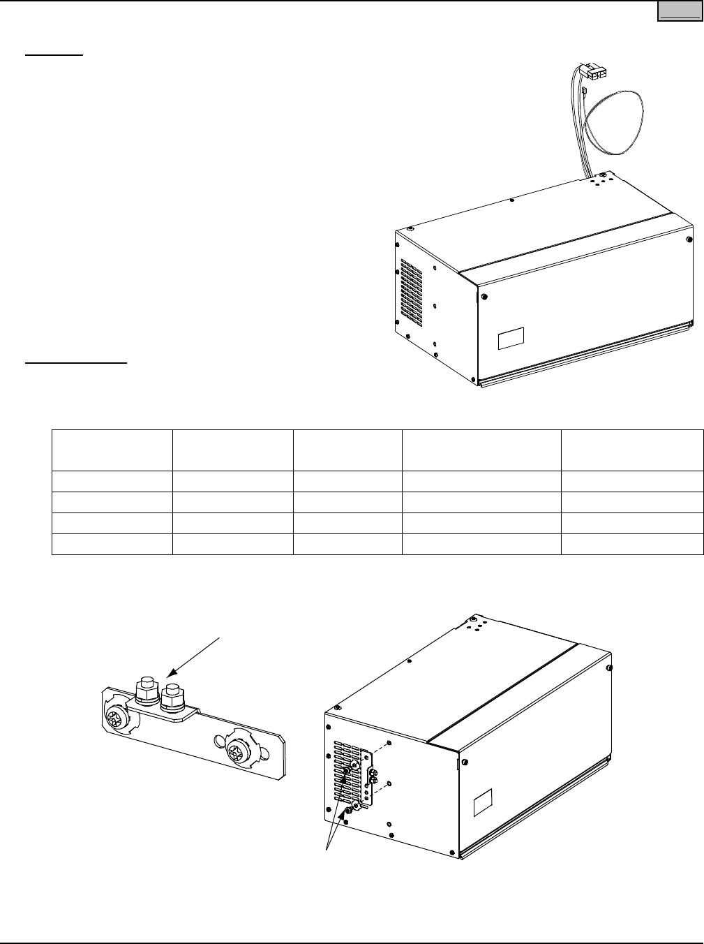
SAG582136600 System Application Guide
Issue AU, February 21, 2014 Spec. No. 582136600 (Model 211NGFB)
Page 58 of 105
This document is property of Emerson Network Power, Energy Systems, North America, Inc. and contains confidential and proprietary information owned by Emerson Network Power, Energy
Systems, North America, Inc. Any copying, use, or disclosure of it without the written permission of Emerson Network Power, Energy Systems, North America, Inc. is strictly prohibited.
NetSure™ 211BC Battery Cabinet (Spec. No. 545506)
Features
♦ The NetSure™ 211BC Battery Cabinet is rated at 30
amperes, and can be mounted in a 23” nominal relay
rack, or mounted to a suitable wall.
♦ The Battery Cabinet contains one (1) 40 ampere
battery disconnect circuit breaker.
♦ Battery circuit breaker alarm leads are provided to tie
into the power system’s alarm circuit.
♦ The Battery Cabinet is equipped with a battery cable
terminated in an Anderson connector.
♦ Cables to connect the batteries (as specified in the
table under Ordering Notes) into the Battery Cabinet
provided.
♦ Battery Cabinets can be paralleled to provide greater
reserve time. Battery cabinets contain a second
Anderson battery connector for plugging one cabinet
into another.
Ordering Notes
1) Order by Spec. No. 545506 as required.
2) Also order four (4) batteries per Battery Cabinet per
the following table.
Battery
Manufacturer
Manufacturer
P/N
Emerson P/N Capacity Amp-Hours
(8Hr rate)
Weight (lb)
per Battery
Enersys
SBS B10
140553
38
28.20
Enersys
SBS 40
140581
38
28.00
C&D/ Dynasty
TEL12-30
140455
30.5
26.70
C&D/ Dynasty
TEL12-45
140454
46
26.70
3) When wall mounted, also order a battery cabinet frame grounding landing point adapter P/N 556872.
This adapter installs in the relay rack mounting bracket holes located on either side of the cabinet.
Attach Frame Ground Landing
Point Adapter to Cabinet
Frame GroundingPoint
(1/4-20 Studson 5/8” Centers)
Frame Ground Landing
Point Adapter P/N 55687
2
Home
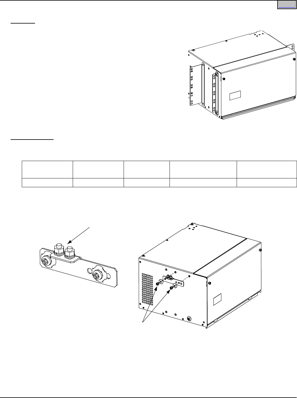
System Application Guide SAG582136600
Spec. No. 582136600 (Model 211NGFB) Issue AU, February 21, 2014
Page 59 of 105
This document is property of Emerson Network Power, Energy Systems, North America, Inc. and contains confidential and proprietary information owned by Emerson Network Power, Energy
Systems, North America, Inc. Any copying, use, or disclosure of it without the written permission of Emerson Network Power, Energy Systems, North America, Inc. is strictly prohibited.
NetSure™ 211BC Battery Cabinet (Spec. No. 554631)
Features
♦ The NetSure™ 211BC Battery Cabinet is rated at 30
amperes, and can be mounted in a 19” or 23” nominal relay
rack, or mounted to a suitable wall.
♦ The Battery Cabinet contains one (1) 40 ampere battery
disconnect circuit breaker.
♦ Battery circuit breaker alarm leads are provided to tie into the
power system’s alarm circuit.
♦ The Battery Cabinet is equipped with a battery cable
terminated in an Anderson connector.
♦ Cables to connect the batteries (as specified in the table
under Ordering Notes) into the Battery Cabinet provided.
♦ Battery Cabinets can be paralleled to provide greater reserve
time. Battery cabinets contain a second Anderson battery
connector for plugging one cabinet into another.
Ordering Notes
1) Order by Spec. No. 554631 as required.
2) Also order four (4) batteries per Battery Cabinet per the following table.
Battery
Manufacturer
Manufacturer
P/N
Emerson P/N Capacity Amp-Hours
(8Hr rate)
Weight (lb)
per Battery
GNB M12V40F 241173815 40 39.00
Note: When wall mounted, a battery cabinet frame grounding landing point adapter, P/N 556872, is
provided. This adapter installs in the relay rack mounting bracket holes located on either side of the
cabinet.
Attach Frame Ground Landing
Point Adapter to Cabinet
Frame Grounding Point
(1/4-20 Studs on 5/8” Centers)
Frame Ground Landing
Point Adapter P/N 556872
Home
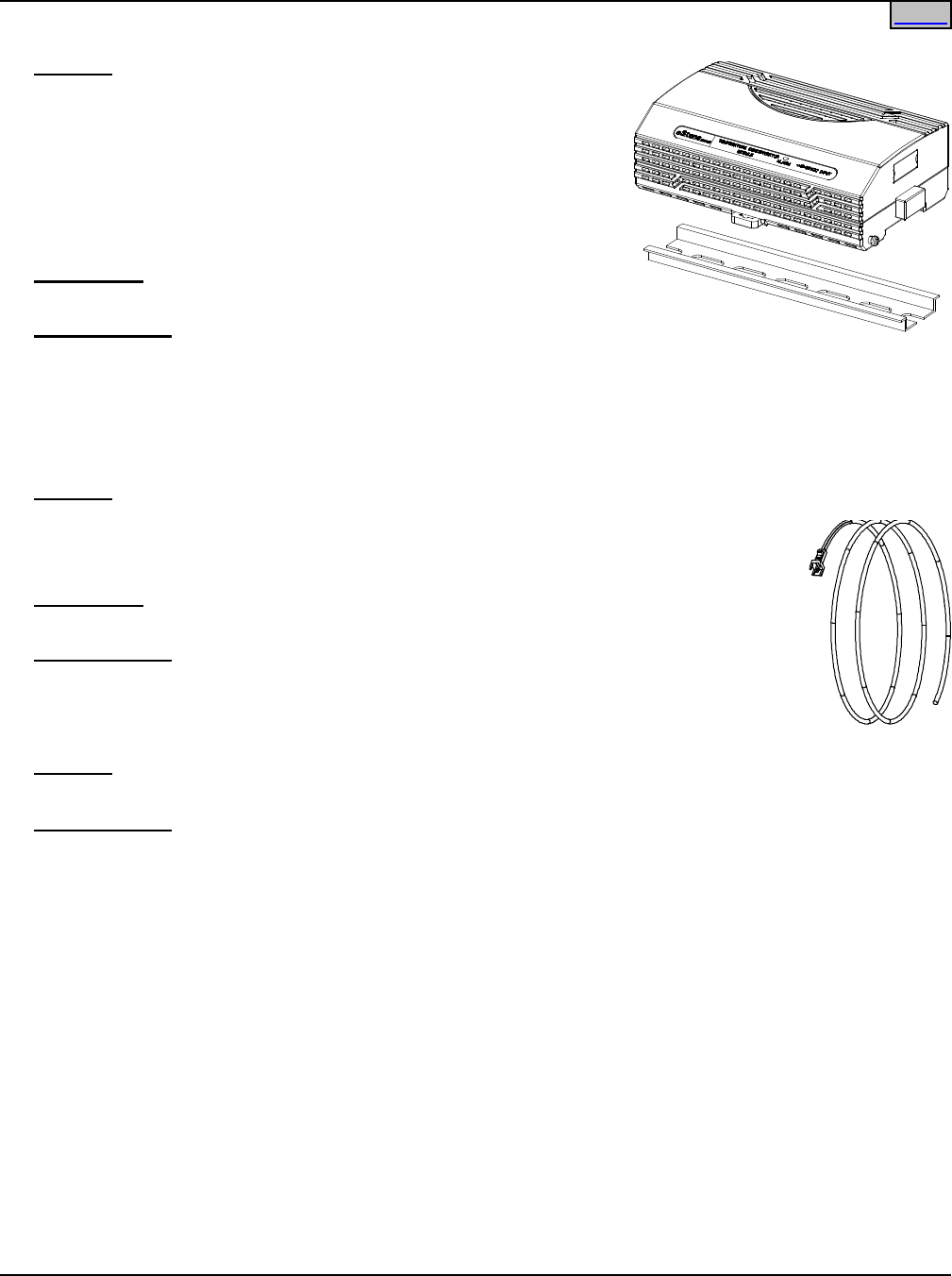
SAG582136600 System Application Guide
Issue AU, February 21, 2014 Spec. No. 582136600 (Model 211NGFB)
Page 60 of 105
This document is property of Emerson Network Power, Energy Systems, North America, Inc. and contains confidential and proprietary information owned by Emerson Network Power, Energy
Systems, North America, Inc. Any copying, use, or disclosure of it without the written permission of Emerson Network Power, Energy Systems, North America, Inc. is strictly prohibited.
SM TEMP Temperature Concentrator (P/N 547490)
Features
♦ Allows for multiple temperature probes to be used for
temperature compensation. Compensation can be based on
highest probe temperature or average probe temperature.
♦ Provides (8) temperature probe inputs per SM TEMP.
♦ Can be cascaded up to (8) SM TEMP modules, connecting up to
64 temperature probes.
♦ Provides analog output for all controllers.
Restrictions
Concentrator needs to plug into analog temp input on IB2 board.
Ordering Notes
1) Order P/N 547490.
2) Order up to (8) 3-meter (P/N 547749) or 10-meter (P/N 547750) temperature probes for each
concentrator.
SM Module RS-485 Interface Cable P/N 547674
Features
♦ Provides 4’ cable for connecting SM supervisory modules to the system RS-485
interface connector.
♦ For interface with SM AC, SM BAT, SM BRC, or SM IO modules.
Restrictions
One (1) RS-485 connector is available in the system.
Ordering Notes
1) Order P/N 547674 as required.
PCU Blank Filler Panel, P/N PSK4820R-1
Features
♦ Provides 1x2U blank filler panel for rectifier module.
Ordering Notes
1) Order P/N PSK4820R-1 as required.
Home
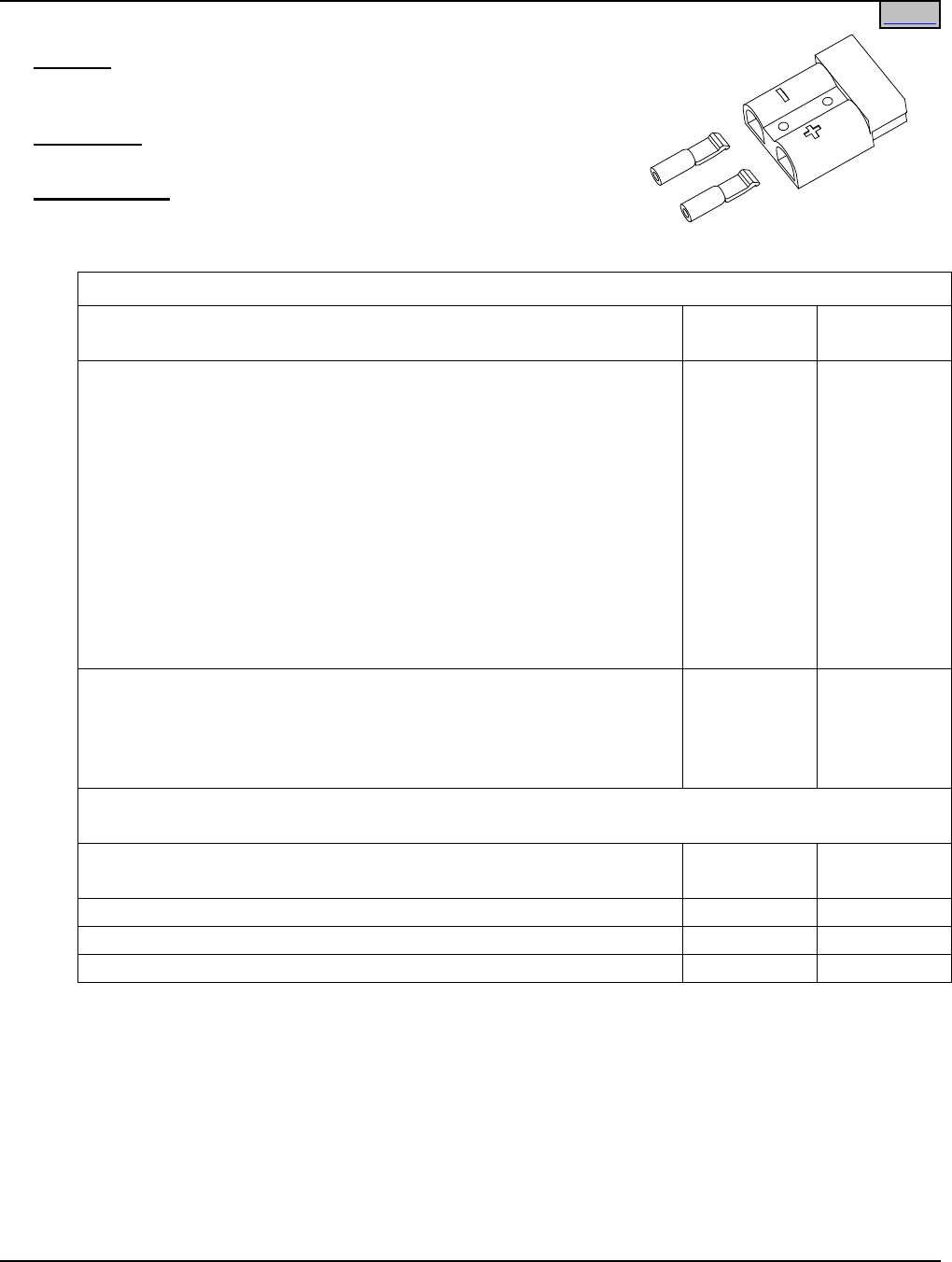
System Application Guide SAG582136600
Spec. No. 582136600 (Model 211NGFB) Issue AU, February 21, 2014
Page 61 of 105
This document is property of Emerson Network Power, Energy Systems, North America, Inc. and contains confidential and proprietary information owned by Emerson Network Power, Energy
Systems, North America, Inc. Any copying, use, or disclosure of it without the written permission of Emerson Network Power, Energy Systems, North America, Inc. is strictly prohibited.
Anderson Battery Connector
Features
♦ Includes the components necessary to assemble an Anderson
connector onto a battery cable.
Restrictions
Appropriate battery post mating lugs must be ordered separately.
Ordering Notes
Order Anderson connector housings and lugs per the following table.
Single Part Number for a Housing and Lugs
Description Emerson
P/N
Anderson
P/N
For a single string (spare for List 71).
Consists of two (2) lugs (Anderson P/N 5952) and one (1) Red
Connector (Anderson P/N 992G1). Lugs accept 8 AWG wire.
Allows for the connection of one (1) battery string (both polarities)
(one wire per lug).
For a single string (spare for List 73).
Consists of two (2) lugs (Anderson P/N 5900) and one (1) Red
Connector (Anderson P/N 992G1). Lugs accept 6 AWG wire.
Allows for the connection of one (1) battery string (both polarities)
(one wire per lug).
(not available
in kit form,
order
components
individually
per the
second half
of this table)
(not available
in kit form,
order
components
individually
per the
second half
of this table)
For a double string (spare for List 72).
Consists of two (2) lugs (Anderson P/N 5900) and one (1) Red
Connector (Anderson P/N 992G1). Lugs accept 6 AWG wires.
Allows for the connection of two (2) battery strings (both polarities)
(two [10 AWG] wires per lug).
133196 6331G1
Individual Housing and Lugs Part Numbers
(spare for List 1, 2, 71, and 73)
Description Emerson
P/N
Anderson
P/N
Housing
138922
992G1
Lug (accepts 8 AWG wire) (2 required per housing)
247109602
5952
Lug (accepts 6 AWG wire) (2 required per housing)
111691
5900
Home

SAG582136600 System Application Guide
Issue AU, February 21, 2014 Spec. No. 582136600 (Model 211NGFB)
Page 62 of 105
This document is property of Emerson Network Power, Energy Systems, North America, Inc. and contains confidential and proprietary information owned by Emerson Network Power, Energy
Systems, North America, Inc. Any copying, use, or disclosure of it without the written permission of Emerson Network Power, Energy Systems, North America, Inc. is strictly prohibited.
Home
Digital Input and Relay Output Cables
Features
♦ Lists 1 and 2: Two sets of customer wiring cables are available. One set is for Digital Inputs and Relay
outputs. The other set is for an additional -48V digital input. One half of the Digital Inputs and Relay
Outputs cable is provided and factory connected in the shelf. The other half (includes mating connector
on one end and un-terminated on the other end) must be ordered separately. The additional -48V digital
input cable must be ordered separately. When ordered, one half of the -48V digital input cable is factory
connected in the shelf. The other half has a mating connector on one end and is un-terminated on the
other end.
♦ Lists 5 and 6: Two sets of customer wiring cables are available. One set is for the Digital Inputs and
another set, for the Relay Outputs. One half of the Relay Outputs Cable is provided and factory
connected in the shelf. The other half (includes mating connector on one end and un-terminated on the
other end) must be ordered separately. Both halves of the Digital Inputs Cable must be ordered
separately. When ordered, one half of the Digital Inputs Cable is factory connected in the shelf. The
other half has a mating connector on one end and is un-terminated on the other end.
Ordering Notes
1) Lists 1 and 2: For the Digital Inputs and Relay Outputs Cable, P/N 545494 (2 ft.) is provided and factory
connected in the List 1 and 2 shelves. The mating cable, P/N 545495 (10 ft.) must be ordered separately.
For additional -48V Digital Input Cable Kit, order P/N 554935.
2) Lists 5 and 6: For the Relay Outputs Cable, P/N 541308 (3 ft.) is provided and factory connected in the
List 5 and 6 shelves. A mating cable, P/N 541309 (10 ft.) or P/N 545644 (50 ft.), must be ordered
separately.
For the Digital Inputs Cable, order P/N 541310 (shelf side, 3 ft.) and P/N 541311 (customer side, 10 ft.).
Note: A custom digital input cable and internal wiring kit is available, P/N 545594. This kit is factory
installed only.
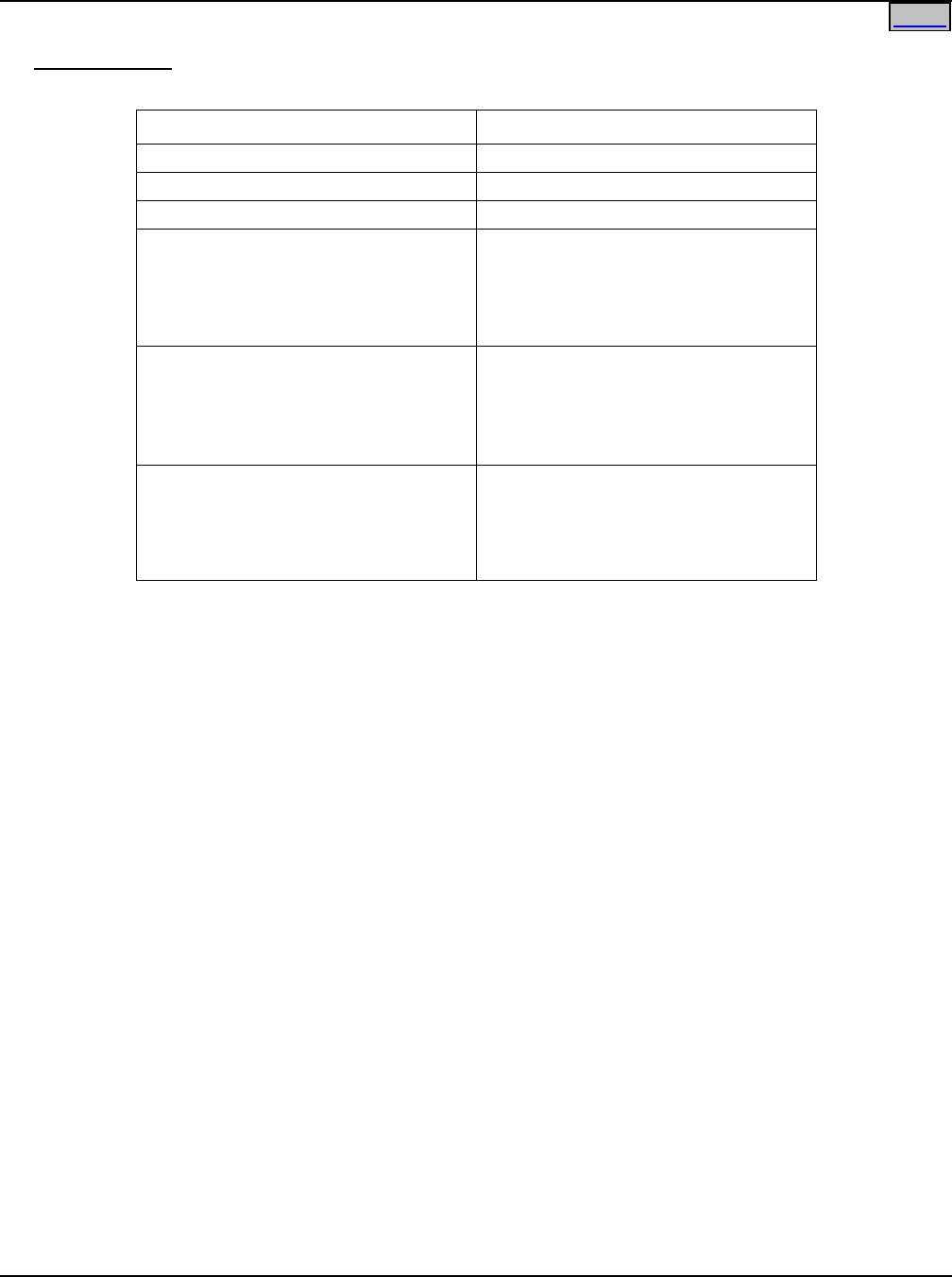
System Application Guide SAG582136600
Spec. No. 582136600 (Model 211NGFB) Issue AU, February 21, 2014
Page 63 of 105
This document is property of Emerson Network Power, Energy Systems, North America, Inc. and contains confidential and proprietary information owned by Emerson Network Power, Energy
Systems, North America, Inc. Any copying, use, or disclosure of it without the written permission of Emerson Network Power, Energy Systems, North America, Inc. is strictly prohibited.
Home
Replacement Modules
Ordering Notes
1) Refer to Table 5.
Item Part Number
500W Rectifier Module
1R48500
1000W Rectifier Module
1R481000
Rectifier Module Fan
32010093
SCU+ Controller Module
1M521BNA*
* Also specify the appropriate SCU+
configuration file. Refer to the
configuration file label on your
existing SCU+ Controller.
ACU+ Controller Module
1M820BNA*
* Also specify the appropriate ACU+
configuration file. Refer to the
configuration file label on your
existing ACU+ Controller.
Temperature Probe
Order per List 90 (9 ft. long)
or List 91 (30 Ft. long)
(or if only one piece of the two piece
probe is needed, see the List 90 or 91
description for part numbers)
Table 5
Replacement Module Part Numbers
SAG582136600 System Application Guide
Issue AU, February 21, 2014 Spec. No. 582136600 (Model 211NGFB)
Page 64 of 105
This document is property of Emerson Network Power, Energy Systems, North America, Inc. and contains confidential and proprietary information owned by Emerson Network Power, Energy
Systems, North America, Inc. Any copying, use, or disclosure of it without the written permission of Emerson Network Power, Energy Systems, North America, Inc. is strictly prohibited.
Home
Wiring Notes
Refer also to the next section, Wiring Illustrations.
Shelf Frame Grounding Stud
Features
♦ An M5 frame grounding stud with hardware is provided on the rear of the shelf.
Restrictions
Recommended frame ground wire size is 6 AWG.
AC Input Branch Circuit Protection and Wiring
Features
♦ Each shelf contains one (1) or two (2) side mounted plug-in AC input connector(s).
♦ AC Input Cable Assemblies/Line Cords are available that plug into the shelf’s AC input connector.
Restrictions
Lists 1 and 2 require one (1) AC input branch circuit.
The AC input branch circuit feeds two (2) (List 1) or three (3) (List 2) rectifiers.
Refer to the following table for recommended branch circuit protection.
Lists 5 and 6 require two (2) AC input branch circuits.
Each AC input branch circuit feeds two (2) (List 5) or three (3) (List 6) rectifiers.
Refer to the following table for recommended branch circuit protection.
AC Input Branch Circuit Protection*
System 208/240VAC Input 120VAC Input
500W Rect. 1000W Rect. 500W Rect. 1000W Rect.
58213660001
58213660005
(2-Rectifiers per AC Feed)
15A 15A 15A 20A
58213660002
58213660006
(3-Rectifiers per AC Feed)
15A 20A 20A 25A / 30A
* Protective devices should be of the time-delay or high inrush type.
For correct AC input wire size, use the appropriate AC Input Cable Assembly/Line Cord for each AC input
branch circuit. Refer to AC Input Cables and Line Cords in the ACCESSORY DESCRIPTIONS section of this
document.
External Alarm and Monitoring Wiring
Features
♦ List 5 and 6: Relay output and digital input leads are connected to screw-type terminal blocks located on
the Customer Interface Board mounted inside the shelf. One half of a Relay Outputs Cable is factory
connected to these terminals. The other half (includes mating connector on one end and un-terminated
on the other end) is ordered separately. If ordered, one half of a Digital Input Cable is factory connected
to these terminals. The other half includes a mating connector on one end and is un-terminated on the
other end.
♦ List 1 and 2: Relay output and digital input leads are connected to screw-type terminals located on the
SCU+ Controller Module mounted inside the shelf. One half of a Digital Input/Relay Output Cable is

System Application Guide SAG582136600
Spec. No. 582136600 (Model 211NGFB) Issue AU, February 21, 2014
Page 65 of 105
This document is property of Emerson Network Power, Energy Systems, North America, Inc. and contains confidential and proprietary information owned by Emerson Network Power, Energy
Systems, North America, Inc. Any copying, use, or disclosure of it without the written permission of Emerson Network Power, Energy Systems, North America, Inc. is strictly prohibited.
Home
factory connected to these terminals. The other half (includes mating connector on one end and
un-terminated on the other end) is ordered separately.
If an additional -48V Digital Input cable is ordered, one half of the cable is factory connected in the shelf.
The other half includes mating connector on one end and is un-terminated on the other end. The
additional -48V digital input cable must be ordered separately.
Restrictions
Recommended Wire Size: 22 AWG for Loop Lengths Up to 200 ft.
18-20 AWG for Loop Lengths Over 200 ft.
Load Distribution Wiring (GMT Fuses) (Lists BG and NG only)
Features
♦ Load and load return leads are connected to a screw-type terminal block located on the front of the
Distribution Unit.
Restrictions
The rating of the distribution device determines the wire size requirements. Refer to the American National
Standards Institute (ANSI) approved National Fire Protection Association's (NFPA) National Electrical Code
(NEC) and applicable local codes.
Terminal block wire size capacity is 20 to 12 AWG.
Load Distribution Wiring (GMT Fuses) (Lists BF, LF, and NF only)
Features
♦ Load distribution (GMT fuses) and load return leads are connected to receptacles located inside the
Distribution Unit. Load leads are brought into the right side (as viewed from the front) of the shelf and are
accessible from the front of the shelf. Note that the GMT distribution fuse block accepts two ranges of
fuse amperage sizes, and that two different types of receptacles are provided.
Restrictions
The rating of the distribution device determines the wire size requirements. Refer to the American National
Standards Institute (ANSI) approved National Fire Protection Association's (NFPA) National Electrical Code
(NEC) and applicable local codes.
Ordering Notes
1) Lists 61 provides 12’ long, 16 AWG, load and load return leads that are terminated on one end with the
appropriate mating connector* to plug into the system’s lower amperage rating GMT fuse connector, and
are left un-terminated at the remaining end for connection into customer loads.
* Consists of housing Molex P/N 39-01-2025 and terminals P/N 44476-3112 [loose] or 44476-3111
[reel].
2) Lists 62 provides 12’ long, 14 AWG, load and load return leads that are terminated on one end with the
appropriate mating connector* to plug into the system’s higher amperage rating GMT fuse connector, and
are left un-terminated at the remaining end for connection into customer loads.
* Consists of housing Tyco P/N 350777-1 and terminals Tyco P/N 350551-3 [loose] or Tyco
350537-3 [reel].

SAG582136600 System Application Guide
Issue AU, February 21, 2014 Spec. No. 582136600 (Model 211NGFB)
Page 66 of 105
This document is property of Emerson Network Power, Energy Systems, North America, Inc. and contains confidential and proprietary information owned by Emerson Network Power, Energy
Systems, North America, Inc. Any copying, use, or disclosure of it without the written permission of Emerson Network Power, Energy Systems, North America, Inc. is strictly prohibited.
Home
Load Distribution Wiring (GMT Fuses) (Lists BC, LC, NC, BA, LA, and NA)
Features
♦ Load distribution (GMT fuses) and load return leads are connected to receptacles located inside the
Distribution Unit. Load leads are brought into the right side (as viewed from the front) of the shelf and are
accessible from the front of the shelf.
Restrictions
The rating of the distribution device determines the wire size requirements. Refer to the American National
Standards Institute (ANSI) approved National Fire Protection Association's (NFPA) National Electrical Code
(NEC) and applicable local codes.
Ordering Notes
1) List 60 provides 12’ long, 16 AWG, load and load return leads that are terminated on one end with the
appropriate mating connector* to plug into the system’s GMT fuse connector, and are left un-terminated
at the remaining end for connection into customer loads.
* Consists of housing Molex P/N 39-01-2025 and terminals P/N 44476-3112 [loose] or 44476-3111
[reel].
Load Distribution Wiring (Optional Bullet-Nose-Type 6-Position GMT Fuse Module)
Features
♦ Load and load return leads are connected to a screw-type terminal block located on the front of the Fuse
Module.
Restrictions
The rating of the distribution device determines the wire size requirements. Refer to the American National
Standards Institute (ANSI) approved National Fire Protection Association's (NFPA) National Electrical Code
(NEC) and applicable local codes.
Terminal block wire size capacity is 24 to 14 AWG.
Load Distribution Wiring (Circuit Breakers) (Lists BC, LC, NC, BA, LA, and NA)
Features
♦ Load distribution (circuit breakers) and load return leads terminated in two-hole lugs are connected to
threaded studs located inside the Distribution Unit. Load leads are brought into the right side (as viewed
from the front) of the shelf and are accessible from the front of the shelf.
Restrictions
The rating of the distribution device determines the wire size requirements. Refer to the American National
Standards Institute (ANSI) approved National Fire Protection Association's (NFPA) National Electrical Code
(NEC) and applicable local codes.
All lugs for customer connections must be ordered separately. Mounting hardware is factory supplied.
Maximum wire size is 6 AWG when all four (4) circuit breaker positions are used. 4 AWG or 2 AWG can be
used, but the number of breaker positions will be reduced as follows;
• 4 AWG: 3 breakers max. (2 load/1 battery or 1 load/2 battery on lists BA, LA, and NA; 3 load on lists BC,
LC, and NC). Use 6 AWG for CO Ground.
• 2 AWG: 2 breakers max. (1 load/1 battery on lists BA, LA, and NA; 2 load on lists BC, LC, and NC). Use
6 AWG for CO Ground.
For 4 AWG and 2 AWG wire, install a customer supplied flat washer between the lug and the nut supplied on
the termination.
Ordering Notes
1) The rating of the distribution device determines the wire size requirements. For wire size and lug
selection, refer to Table 6.
2) For other available lugs, refer to drawings 031110100 through 031110300.
System Application Guide SAG582136600
Spec. No. 582136600 (Model 211NGFB) Issue AU, February 21, 2014
Page 67 of 105
This document is property of Emerson Network Power, Energy Systems, North America, Inc. and contains confidential and proprietary information owned by Emerson Network Power, Energy
Systems, North America, Inc. Any copying, use, or disclosure of it without the written permission of Emerson Network Power, Energy Systems, North America, Inc. is strictly prohibited.
Home
Circuit
Breaker
Amperag
e
Recm 90
°
C Wire Size (1)
14 AWG
12 AWG
10 AWG
8 AWG
6 AWG
4 AWG
2 AWG
Loop Length (feet) (2)
1, 3, 5,
10A
37 (3, 4, 5) 58 (3, 4, 5) 93 (3, 4, 5) 148 (3, 4, 5) 236 (3, 4, 5) -- --
15A
24
(3, 4)
39
(3, 4, 5)
62
(3, 4, 5)
99
(3, 4, 5)
157
(3, 4, 5)
-- --
20A
--
29 (3, 4)
46 (3, 4, 5)
74 (3, 4, 5)
118 (3, 4, 5)
--
--
25A
--
--
37 (3, 4,)
59 (3, 4, 5)
94 (3, 4, 5)
--
--
30A
--
--
31 (3, 4)
49 (3, 4, 5)
78 (3, 4, 5)
--
--
35A
--
--
--
42 (3, 4)
67 (3, 4, 5)
107 (3, 4)
--
40A -- -- -- 37
(3, 4)
59
(3, 4, 5)
94
(3, 4)
--
45A
--
--
--
33 (3, 4)
52 (3, 4)
83 (3, 4)
--
50A
--
--
--
29 (3)
47 (3, 4,)
75 (3, 4)
--
60A
--
--
--
--
39 (3, 4)
62 (3, 4)
99 (3, 4)
70A
53 (3, 4)
85 (3, 4)
75A
50 (3, 4)
79 (3, 4)
80A
47 (3, 4)
74 (3, 4)
90A
41
(3)
66
(3, 4)
100A
--
59 (3, 4)
Recommended Crimp Lug (6)
2-hole
24539010
0
24539010
0
24539010
0
24534660
0
24534650
0
24534680
0
24534690
0
1 Wire sizes are based on recommendations of the American National Standards Institute (ANSI)
approved National Fire Protection Association's (NFPA) National Electrical Code (NEC). Table 310-16
for wire rated at 90
°
C conductor temperature operating in ambient temperatures of 40
°
C, 50°C, and
65°C was used. For other operating ambient temperatures, refer to the NEC. For operation in
countries where the NEC is not recognized, follow applicable codes.
2 Recommended wire sizes are sufficient to restrict voltage drop to 1.0 volt or less at listed branch current
for the loop lengths shown. Loop length is the sum of the lengths of the positive and negative leads.
3 Wire Size / Loop Length Combination Calculated using 40°C Ambient Operating Temperature.
4 Wire Size / Loop Length Combination Calculated using 50°C Ambient Operating Temperature.
5 Wire Size / Loop Length Combination Calculated using 65°C Ambient Operating Temperature.
6 Two-hole lugs are 10-32 bolt clearance on 5/8" centers. Refer to drawing 031110100 for lug crimping
information.
Table 6
Recommended Battery and Load Distribution Wire Size and Lug Selection
(Bullet Nose-Type Circuit Breaker)

SAG582136600 System Application Guide
Issue AU, February 21, 2014 Spec. No. 582136600 (Model 211NGFB)
Page 68 of 105
This document is property of Emerson Network Power, Energy Systems, North America, Inc. and contains confidential and proprietary information owned by Emerson Network Power, Energy
Systems, North America, Inc. Any copying, use, or disclosure of it without the written permission of Emerson Network Power, Energy Systems, North America, Inc. is strictly prohibited.
Home
Load Distribution Wiring (GMT Fuses) (List KG)
Features
♦ Load distribution (GMT fuses) and load return leads are connected to terminal blocks located on the front
of the assembly.
Restrictions
The rating of the distribution device determines the wire size requirements. Refer to the American National
Standards Institute (ANSI) approved National Fire Protection Association's (NFPA) National Electrical Code
(NEC) and applicable local codes.
Terminal block wire size capacity is 26 to 14 AWG.
CO Ground Wiring (Lists BF, LF, NF, BC, LC, NC, BA, LA, and NA)
Features
♦ Two 10-32 studs on 5/8” centers with hardware are provided on the Return Bus for CO Ground wiring.
Restrictions
Recommended CO ground wire size is 6 AWG.
Recommended lug is 245346500 (2-hole, 10-32 clearance holes, 5/8” centers).
Input Battery Wiring (List BG and NG)
Features
♦ Two (2) 8 AWG 48” long battery cables are factory connected inside the shelf. These cables are
terminated at the customer end in a Red SB50 Anderson battery connector. A mating Anderson battery
connector is provided [Housing: Emerson P/N 138922, Anderson Power Products P/N 992G1. Contacts
(two provided): Emerson P/N 247109602, Anderson Power Products P/N 5952].
♦ Additional strings of battery may be connected to the system using the available battery cable kits (see
List 71 and List 72).
Restrictions
Battery leads are NOT internally fused.
Input Battery Wiring (to Battery Disconnect Circuit Breakers) (Lists BA, LA, and NA)
Features
♦ Battery and battery return leads terminated in two-hole lugs are connected to threaded studs located
inside the Distribution Unit. Battery leads are brought into the right side (as viewed from the front) of the
shelf and are accessible from the front of the shelf.
Restrictions
The rating of the distribution device determines the wire size requirements. Refer to the American National
Standards Institute (ANSI) approved National Fire Protection Association's (NFPA) National Electrical Code
(NEC) and applicable local codes.
All lugs for customer connections must be ordered separately. Mounting hardware is factory supplied.
Maximum wire size is 6 AWG when all four (4) circuit breaker positions are used. 4 AWG or 2 AWG can be
used, but the number of breaker positions will be reduced as follows;
• 4 AWG: 3 breakers max. (2 load/1 battery or 1 load/2 battery on lists BA, LA, and NA; 3 load on lists BC,
LC, and NC). Use 6 AWG for CO Ground.
• 2 AWG: 2 breakers max. (1 load/1 battery on lists BA, LA, and NA; 2 load on lists BC, LC, and NC). Use
6 AWG for CO Ground.
For 4 AWG and 2 AWG wire, install a customer supplied flat washer between the lug and the nut supplied on
the termination.

System Application Guide SAG582136600
Spec. No. 582136600 (Model 211NGFB) Issue AU, February 21, 2014
Page 69 of 105
This document is property of Emerson Network Power, Energy Systems, North America, Inc. and contains confidential and proprietary information owned by Emerson Network Power, Energy
Systems, North America, Inc. Any copying, use, or disclosure of it without the written permission of Emerson Network Power, Energy Systems, North America, Inc. is strictly prohibited.
Ordering Notes
1) The rating of the distribution device determines the wire size requirements. For wire size and lug
selection, refer to Table 6.
2) For other available lugs, refer to drawings 031110100 through 031110300.
Input Battery Wiring (to Battery Busbars) (Lists BF, LF, NF, BC, LC, and NC)
Features
♦ Battery and battery return leads terminated in two-hole lugs are connected to threaded studs located
inside the Distribution Unit. Battery leads are brought into the right side (as viewed from the front) of the
shelf and are accessible from the front of the shelf.
Restrictions
All lugs for customer connections must be ordered separately. Mounting hardware is factory supplied.
Maximum size of wire to be connected to a single lug position is 2 AWG.
Maximum lug width, 0.61 inches.
Ordering Notes
1) Battery wire size varies depending on load, therefore no specific information is provided for wire size.
When making connections, observe correct polarity.
2) List 65 and List 66 provide 2 AWG “shelf side” and “battery side” (respectively) battery cables.
Home
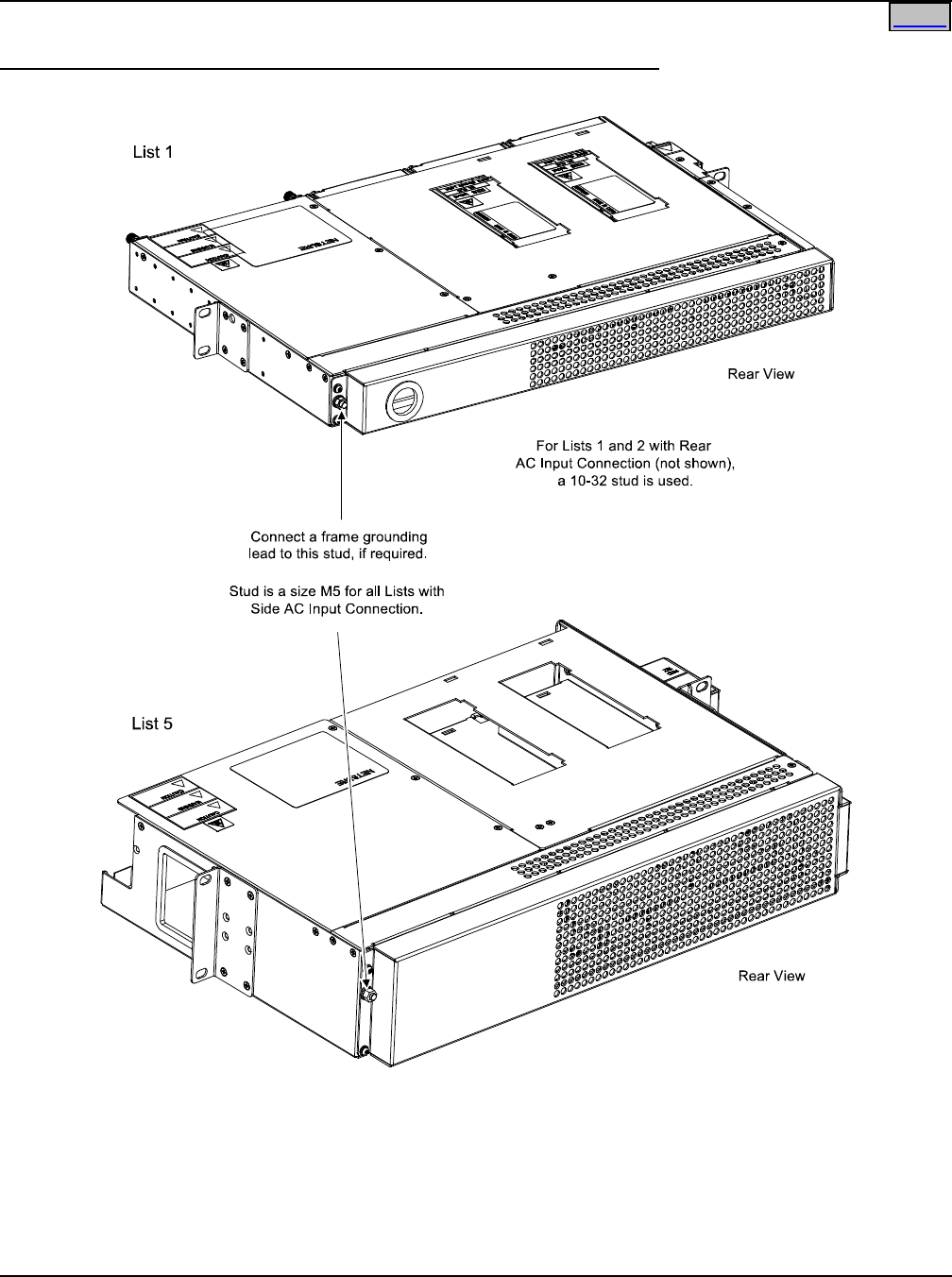
SAG582136600 System Application Guide
Issue AU, February 21, 2014 Spec. No. 582136600 (Model 211NGFB)
Page 70 of 105
This document is property of Emerson Network Power, Energy Systems, North America, Inc. and contains confidential and proprietary information owned by Emerson Network Power, Energy
Systems, North America, Inc. Any copying, use, or disclosure of it without the written permission of Emerson Network Power, Energy Systems, North America, Inc. is strictly prohibited.
Home
Wiring Illustrations
Shelf Frame Grounding Stud (both 1U and 2U Panels, List 1 and 5 shown)
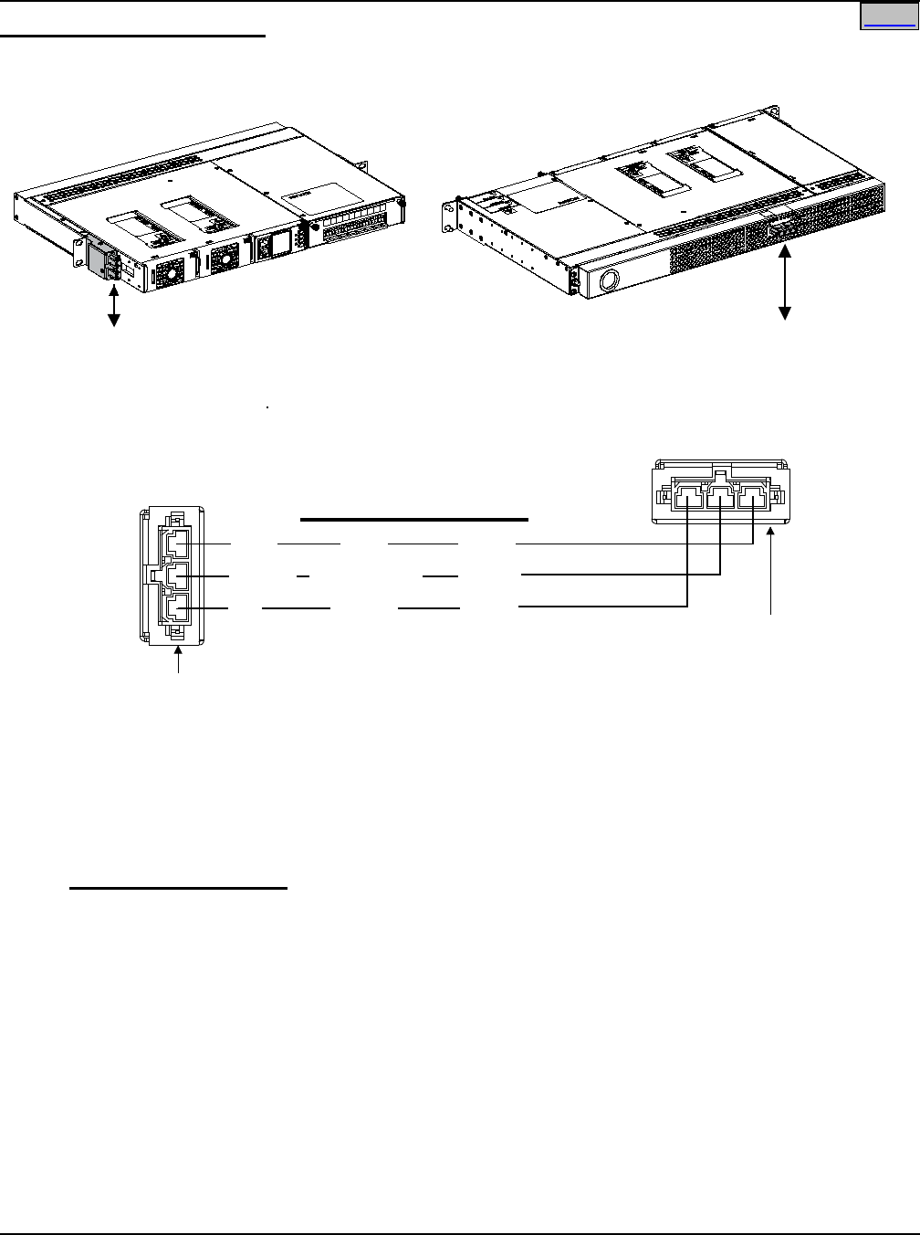
System Application Guide SAG582136600
Spec. No. 582136600 (Model 211NGFB) Issue AU, February 21, 2014
Page 71 of 105
This document is property of Emerson Network Power, Energy Systems, North America, Inc. and contains confidential and proprietary information owned by Emerson Network Power, Energy
Systems, North America, Inc. Any copying, use, or disclosure of it without the written permission of Emerson Network Power, Energy Systems, North America, Inc. is strictly prohibited.
Home
AC Input Wiring (Lists 1 and 2)
List 1 and List 2 with Side AC Input Connectors
(List 1 shown)
List 1 and List 2 with Rear AC Input Connectors
(List 2 shown)
Front
* Rectifiers are numbered left to
right as viewed from the front.
Rear
AC input connections are
made using the supplied AC
input cable assemblies/
line cords connected here.
AC input connections are
made using the supplied AC
input cable assemblies/
line cords connected here.
Front View
Nominal 120/208/240V
AC Input for Rectifier Module:
List 1 (19” Shelf): #1 and #2
List 2 (23” Shelf): #1, #2, and # 3
Blue*
Green/Yellow*
Brown*
White*
Green*
Black*
L2-N
Ground
L1
* color of AC Input Cable
Assembly/Line Cord lead.
AC Input
Cable Assembly
AC Input
Line Cord
ENSURE THE PROPER VOLTAGE AC
BRANCH CIRCUIT AND LINE CORDS
WITH THE APPROPRIATE PLUG
ARE USED FOR YOUR APPLICATION.
500W Rectifier: 120/208/240 VAC Input
1000W Rectifier: 120/208/240 VAC Input
“WARNING - HIGH LEAKAGE CURRENT.”
An industrial style plug is required when
providing power to three (3) or more Rectifier
Modules with a flexible cord. Plug and
outlet types 1-15, 2-15, 2-20, 5-15, and 5-20
as specified in IEC 60083 are considered
to be NON-INDUSTRIAL within the meaning
of this standard.
* AC Input Cable Assembly / Line Cords
Part Number Customer End
535232 unterminated (List 1 & 2)
540946 L6-30P (List 1 & 2)
545252 L5-30P (List 1 & 2)
545478 5-15P (List 1 w/ R48-500)
545479 L5-15P (List 1 w/ R48-500)
545480 L6-15P (List 1; List 2 w/ R48-500)
545481 L5-20P (List 1; List 2 w/ R48-500)
545553 L6-20P (List 1 & 2)
545616 L6-30P (List 1 & 2)
547525 L5-30P (List 1 & 2)
548457 5-15P (List 1 w/ R48-500)
548196 IEC320 C20 (List 1 120/208/240V & List 2 208/240
w/ R48-500 or R48-1000; List 2 120V w/ R48-500 only.)
Rear View
Nominal 120/208/240V
AC Input for Rectifier Module:
List 1 (19” Shelf): #1 and #2
List 2 (23” Shelf): #1, #2, and # 3
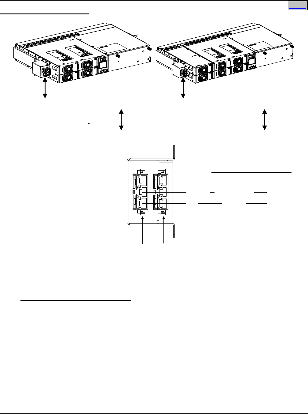
SAG582136600 System Application Guide
Issue AU, February 21, 2014 Spec. No. 582136600 (Model 211NGFB)
Page 72 of 105
This document is property of Emerson Network Power, Energy Systems, North America, Inc. and contains confidential and proprietary information owned by Emerson Network Power, Energy
Systems, North America, Inc. Any copying, use, or disclosure of it without the written permission of Emerson Network Power, Energy Systems, North America, Inc. is strictly prohibited.
Home
AC Input Wiring (Lists 5 and 6)
List 5List 6
Front
Rectifiersare numbered asshownabove
Front
ACinput connections are
madeusingthesuppliedAC
inputcableassemblies/
line cords connectedhere.
AC input connections are
made using the supplied AC
inputcable assemblies/
linecordsconnectedhere.
Front View
Nominal 120/208/240V
AC Input for RectifierModule:
List 5 (19” Shelf): #1 and #2
List 6 (23” Shelf): #1, #2, and #5
Blue*
Green/Yellow*
Brown*
White*
Green*
Black*
L2-N
Ground
L1
* color of AC Input Cable
Assembly/Line Cord lead.
AC Input
Cable Assembly
AC Input
LineCord
ENSURETHE PROPER VOLTAGE AC
BRANCH CIRCUIT AND LINECORDS
WITH THE APPROPRIATE PLUG
ARE USED FORYOUR APPLICATION.
500WRectifier: 120/208/240VAC Input
1000WRectifier: 120/208/240 VAC Input
“WARNING -HIGH LEAKAGE CURRENT.”
An industrial style plug is required when
providing power to three (3) or more Rectifier
Modules with a flexible cord. Plug and
outlet types 1-15, 2-15, 2-20, 5-15, and 5-20
as specified in IEC 60083 are considered
to be NON-INDUSTRIAL within the meaning
of this standard.
* AC Input Cable Assembly /Line Cords
Part Number Customer End
535232 unterminated (List 5 & 6)
540946 L6-30P (List 5 & 6)
545252 L5-30P (List 5 & 6)
545478 5-15P (List 5 w/ R48-500)
545479 L5-15P (List 5 w/ R48-500)
545480 L6-15P (List 5; List 6 w/ R48-500)
545481 L5-20P (List 5; List 6 w/ R48-500)
545553 L6-20P (List 5 & 6)
545616 L6-30P (List 5 & 6)
547525 L5-30P (List 5 & 6)
548457 5-15P (List 5 w/ R48-500)
548196 IEC320 C20 (List 5 120/208/240V & List 6 208/240
w/ R48-500 or R48-1000; List 6 120V w/ R48-500 only.)
4
2
3
1
4
2
3
1
6
5
Nominal 120/208/240V
AC Input for Rectifier Module:
List5 (19”Shelf): #3 and #4
List 6 (23” Shelf):#3, #4, and #6
Rectifiers are numbered asshown above
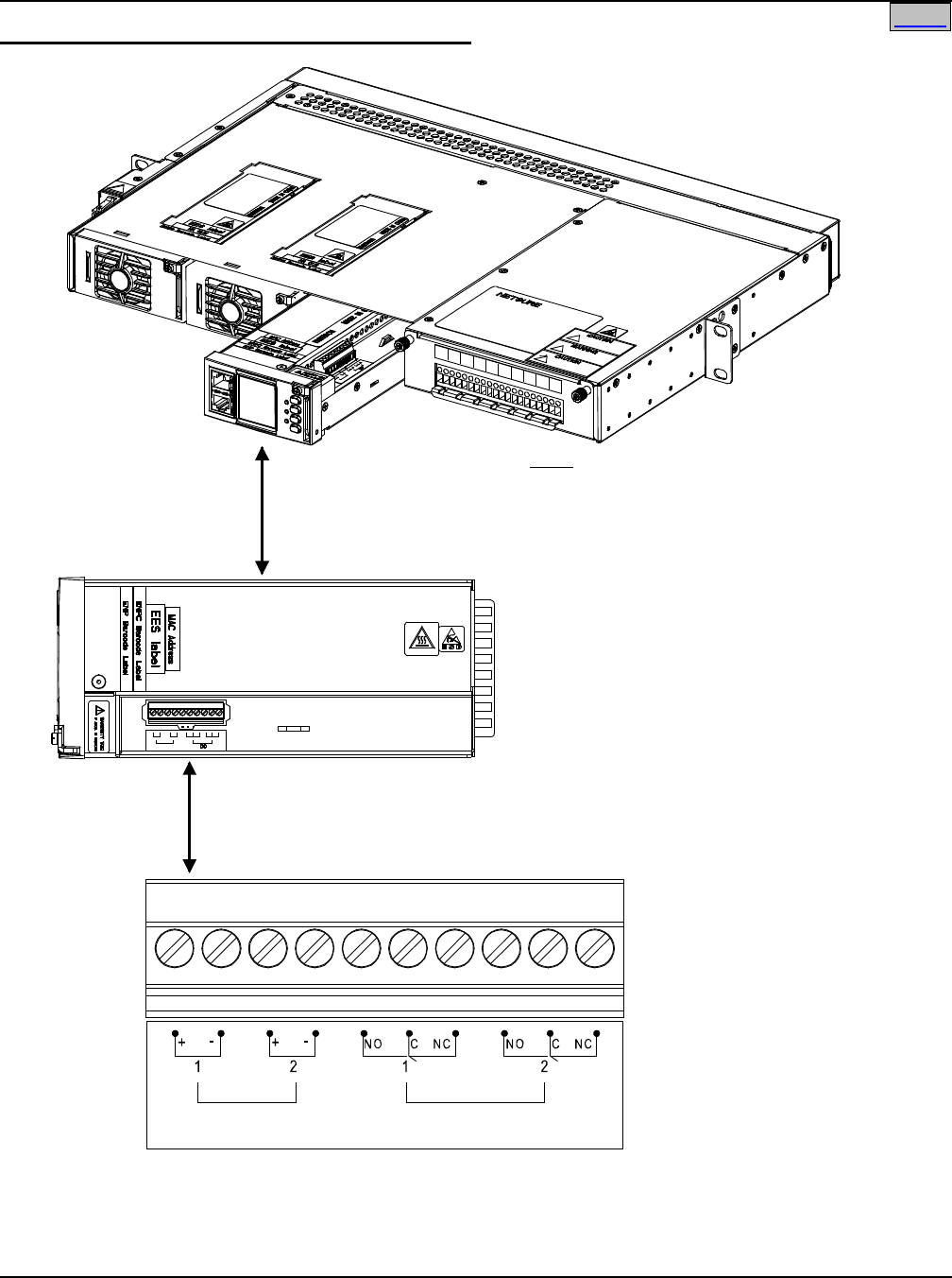
System Application Guide SAG582136600
Spec. No. 582136600 (Model 211NGFB) Issue AU, February 21, 2014
Page 73 of 105
This document is property of Emerson Network Power, Energy Systems, North America, Inc. and contains confidential and proprietary information owned by Emerson Network Power, Energy
Systems, North America, Inc. Any copying, use, or disclosure of it without the written permission of Emerson Network Power, Energy Systems, North America, Inc. is strictly prohibited.
Home
External Alarm and Monitoring Wiring (Lists 1 and 2)
SCU+
Controller Notes
Relay Output/Digital Input Cable P/N 545494
is factory connected to terminals. Mating half
(w/ unterminated ends) available, P/N 545495.
When an additional -48V Digital Input Cable Kit
P/N 554935 is ordered, one half of the kit is
factory connected in the shelf. The other half
has a mating connector on one end and is
un-terminated on the other end.
Digital Input 1 is factory wired to
Load Breaker / Fuse Alarm.
Digital Input 2 default is External Battery
Disconnect Circuit Breaker Alarm.
A factory-connected jumper
supplies +BAT (Battery Return)
to the positive side of Digital
Input #2.
When ordered, Temperature Probe
leads are factory connected
to SCU+ Connector Board
located in the Distribution Unit.
These are labeled T1 and T2.
NC = Normally Closed
COM = Common
NO = Normally Open
All relay contacts are shown
with the relay deenergized.
SCU+ Controller
(Top View)
(48/24V)
Digital Inputs
Major
Summary
Alarm
Minor
Summary
Alarm
Relay Outputs
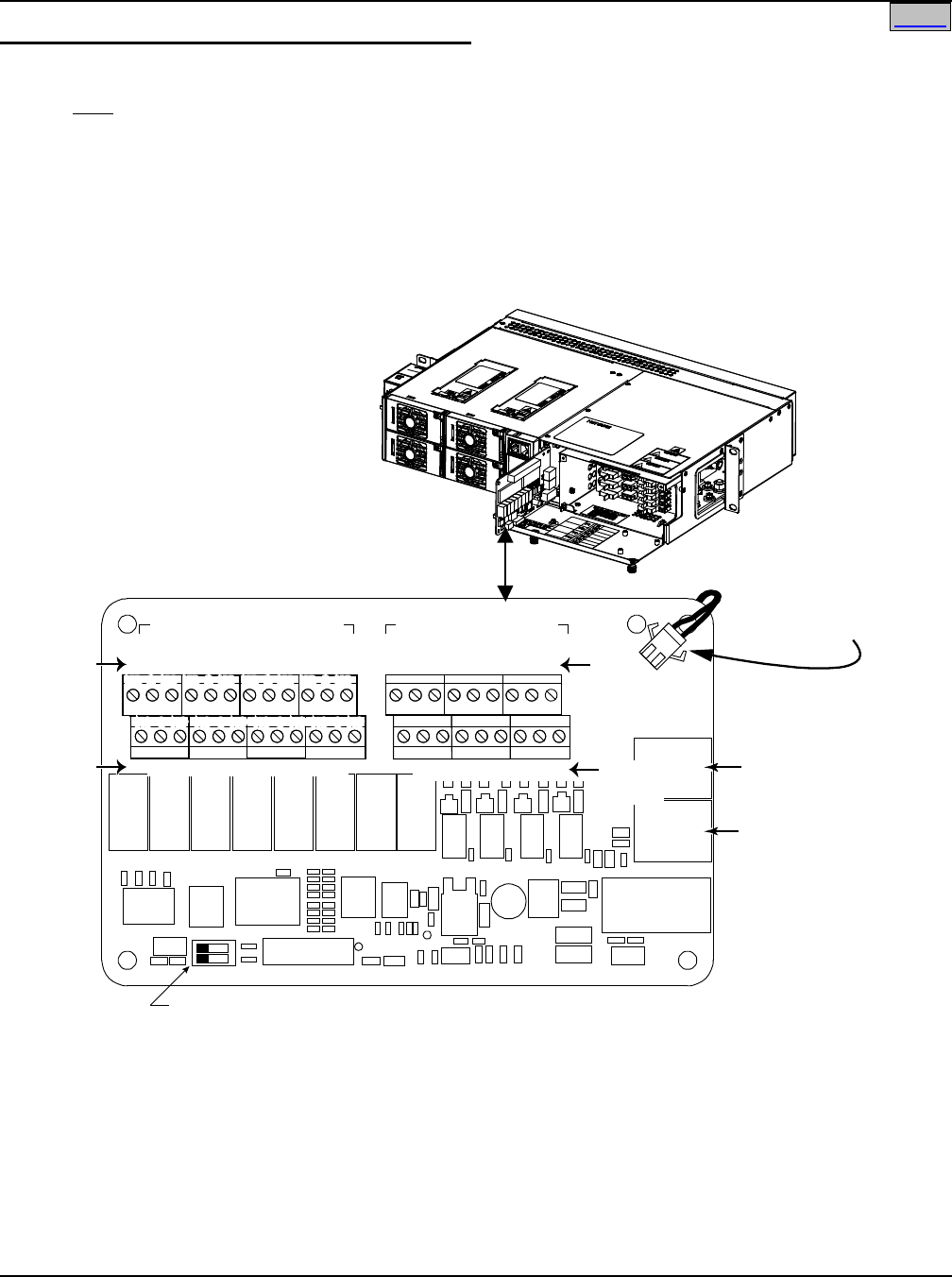
SAG582136600 System Application Guide
Issue AU, February 21, 2014 Spec. No. 582136600 (Model 211NGFB)
Page 74 of 105
This document is property of Emerson Network Power, Energy Systems, North America, Inc. and contains confidential and proprietary information owned by Emerson Network Power, Energy
Systems, North America, Inc. Any copying, use, or disclosure of it without the written permission of Emerson Network Power, Energy Systems, North America, Inc. is strictly prohibited.
Home
External Alarm and Monitoring Wiring (Lists 5 and 6)
Note: A custom digital input cable and internal wiring kit is available, P/N 545594. This kit is factory installed
only.
RS-485 Connection
for SM AC, SM BAT,
SM BRC, or SM IO
Supervisory Modules.
See module data
sheets. (Functional
with ACU+ only.)
Temp. Probe #2
or
SM TEMP Module
Temp. Probe #1
or
SM TEMP Module
Notes
Relay Output Cable P/N 541308 is factory connected to Relay Output terminals.
Mating half (w/ unterminated ends) available, P/N 541309.
If ordered, Digital Input Cable P/N 541310 is factoryconnected to DigitalInput terminals.
Mating half (w/ unterminated ends) available, P/N 541311.
Digital Input 1 is factory wired to Load Breaker / Fuse Alarm.
Digital Input 2 is reserved for ExternalBattery Breaker Alarm.
A factoryconnected jumper supplies +BAT (Battery Return) to the positive
side of DigitalInput 2.
Digital Inputs 3 through 7 are User defined.
Digital Input 8 is reserved forEmergency Stop.
DigitalInput9 is not available in this system.
When ordered, Temperature Probe leads
are factory connected to J11 and J12. These
are labeled 1 and 2.
NC = Normally Closed
COM = Common
NO = Normally Open
All relay conacts are shown
with the relay deenergized.
J1
SW1
J11
J12
Relay Output Term. Blocks Digital Input Term. Blocks
J9 J8 J7 J6 J5 J4 J3
The relay assigned by the Controller to be the”Major Summary” (SCU+) or “Critical Summary” (ACU+) alarm (relay 1 by default)
will operate in the “Fail Safe Mode”. “Fail Safe Mode” means Relay 1 is de-energized during an alarm condition, opening the
contacts between the C and NO terminals, and closing the contacts between the C and NC terminals.
The remaining seven (7) alarm relays energize during an alarm condition, closing the contacts between the C and NO
terminals, and opening the contacts between the C and NC terminals.
*
J2
Switch sections must be set to this position
to interface with SCU+/ACU+ controller.
Relay
No.
18 7 6 5 4 3 2
1
8 7 6 5 4 3 2 Input
No. (–)
Input
No. (+)
NO C NC
NO CNC
NO C NC
NO CNC
NO C NC
NO CNC
NO C NC
NO CNC
5 3 1
46 2
5 3 1
46 2
5 3 1
46 2
531
46 2
5 3 1
46 2
5 3 1
4
6 2
531
46 2
8642
75 3 1*
Relay
No.
IB2 Customer
Interface Board
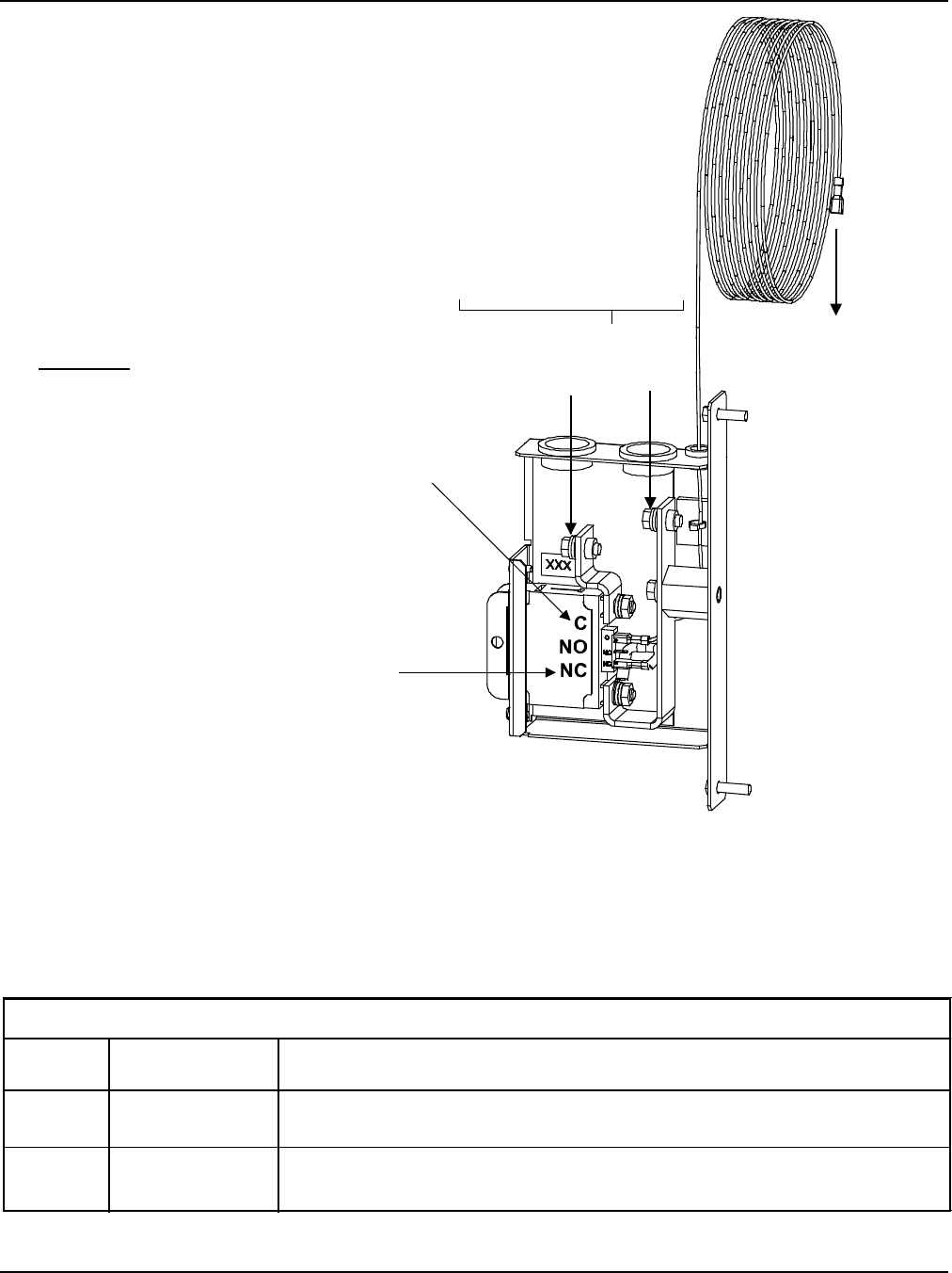
System Application Guide SAG582136600
Spec. No. 582136600 (Model 211NGFB) Issue AU, February 21, 2014
Page 75 of 105
This document is property of Emerson Network Power, Energy Systems, North America, Inc. and contains confidential and proprietary information owned by Emerson Network Power, Energy
Systems, North America, Inc. Any copying, use, or disclosure of it without the written permission of Emerson Network Power, Energy Systems, North America, Inc. is strictly prohibited.
Yellow Alarm Lead
(P/N 535294)
(factory wired to
circuit breaker
alarm terminal)
Connect to shelf
per table below.
Remove quick
connect terminal
first.
Torque to 84 in-lbs
using supplied hardware
To
Power
System
To
Battery
Procedure
1. Connect YELLOW lead exiting top of
Battery Disconnect Unit per table below.
Remove quick connect terminal first.
The YELLOW lead is factory connected
to circuit breaker “C (Common)” alarm
terminal in the Battery Disconnect Unit.
2. There is NO connection to the circuit
breaker “NO (Normally Open)”
alarm terminal.
3. Connect loose end of Jumper factory
connected to bottom terminal on
circuit breaker to circuit breaker
“NC (Normally Closed)” alarm
terminal.
EXTERNAL BATTERY
DISCONNECT UNIT
(Side cover removed in illustration
to show wiring details.)
Alarm Wiring to a Single
External Battery Disconnect Unit
External Battery Disconnect Circuit Breaker Alarm Input:
A battery disconnect circuit breaker alarm is activated when the circuit
breaker is in the OFF position, and provides -48VDC to Digital Input # 2.
Must order Cable 545495
R-BK Lead of 545495. Splice and heat shrink tubing included with 545495
Pin 3 of J3 on customer interface BD (negative side of Digital Input # 2)
O-R Lead of 541311. Splice and heat shrink tubing included with 541311
NO
CONNECT YELLOW WIRE TO:
Alarm Cable
on shelf
YES
NO
YES
545495
541311
Shelf List
1 or 2
5 or 6
BREAKER ALARM CONNECTION
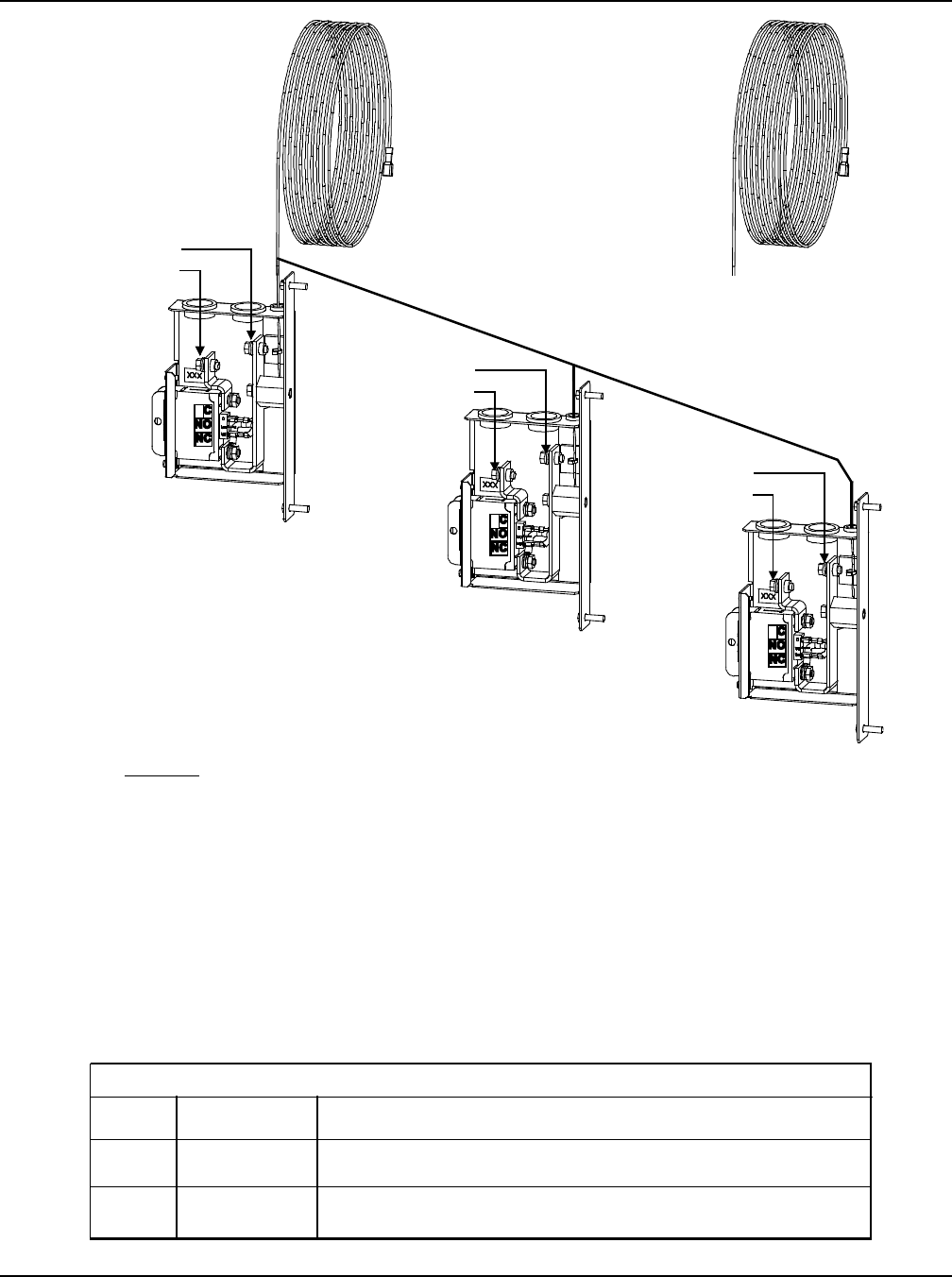
SAG582136600 System Application Guide
Issue AU, February 21, 2014 Spec. No. 582136600 (Model 211NGFB)
Page 76 of 105
This document is property of Emerson Network Power, Energy Systems, North America, Inc. and contains confidential and proprietary information owned by Emerson Network Power, Energy
Systems, North America, Inc. Any copying, use, or disclosure of it without the written permission of Emerson Network Power, Energy Systems, North America, Inc. is strictly prohibited.
Yellow Jumper/Alarm
Lead(P/N 524384)
(Ordered separately
and supplied loose.
Mustbewired
by the customer to
each circuit breaker
“C(Common)”
alarm terminal)Connect to
shelf per
table below.
see
previous
page
Procedure
1. Completely remove YELLOW lead exiting top of
ALL Battery Disconnect Units anddiscard.
2. Connect separately ordered YELLOW jumper/alarm
lead (P/N 524384) to circuit breaker “C (Common)”
alarm terminals in ALL Battery Disconnect Units.
Connect remaining end per table below.
3. There is NO connection to the circuit
breaker “NO (Normally Open)”
alarm terminal.
1st EXTERNAL BATTERY
DISCONNECT UNIT
Alarm Wiring to (2) to (3)
External Battery Disconnect Units
Yellow Alarm Lead
(P/N535294)
(factorywired to
circuit breaker
alarmterminal)
REMOVE
COMPLETELY
FROMALLBATTERY
DISCONNECT UNITS
AND DISCARD.
(Side cover removedin illustration
to show wiring details.)
2nd EXTERNAL BATTERY
DISCONNECT UNIT
3rd EXTERNAL BATTERY
DISCONNECT UNIT
see
previous
page
see
previous
page
4. In ALL Battery Disconnect Units,
connect loose end ofJumper factory
connected to bottom terminal on
circuit breaker to circuit breaker
“NC (Normally Closed)”
alarm terminal.
*No terminal
on 524384
jumper
External Battery Disconnect Circuit Breaker Alarm Input:
Abattery disconnect circuit breaker alarm is activated when the circuit
breaker is in the OFF position, and provides -48VDC to Digital Input # 2.
Must order Cable 545495
R-BK Lead of 545495. Splice and heat shrink tubing included with 545495
Pin 3 of J3 on customer interface BD (negative side of Digital Input # 2)
O-R Lead of 541311. Splice and heat shrink tubing included with 541311
NO
CONNECT YELLOW WIRE TO:
Alarm Cable
on shelf
YES
NO
YES
545495
541311
Shelf List
1 or 2
5 or 6
BREAKER ALARM CONNECTION
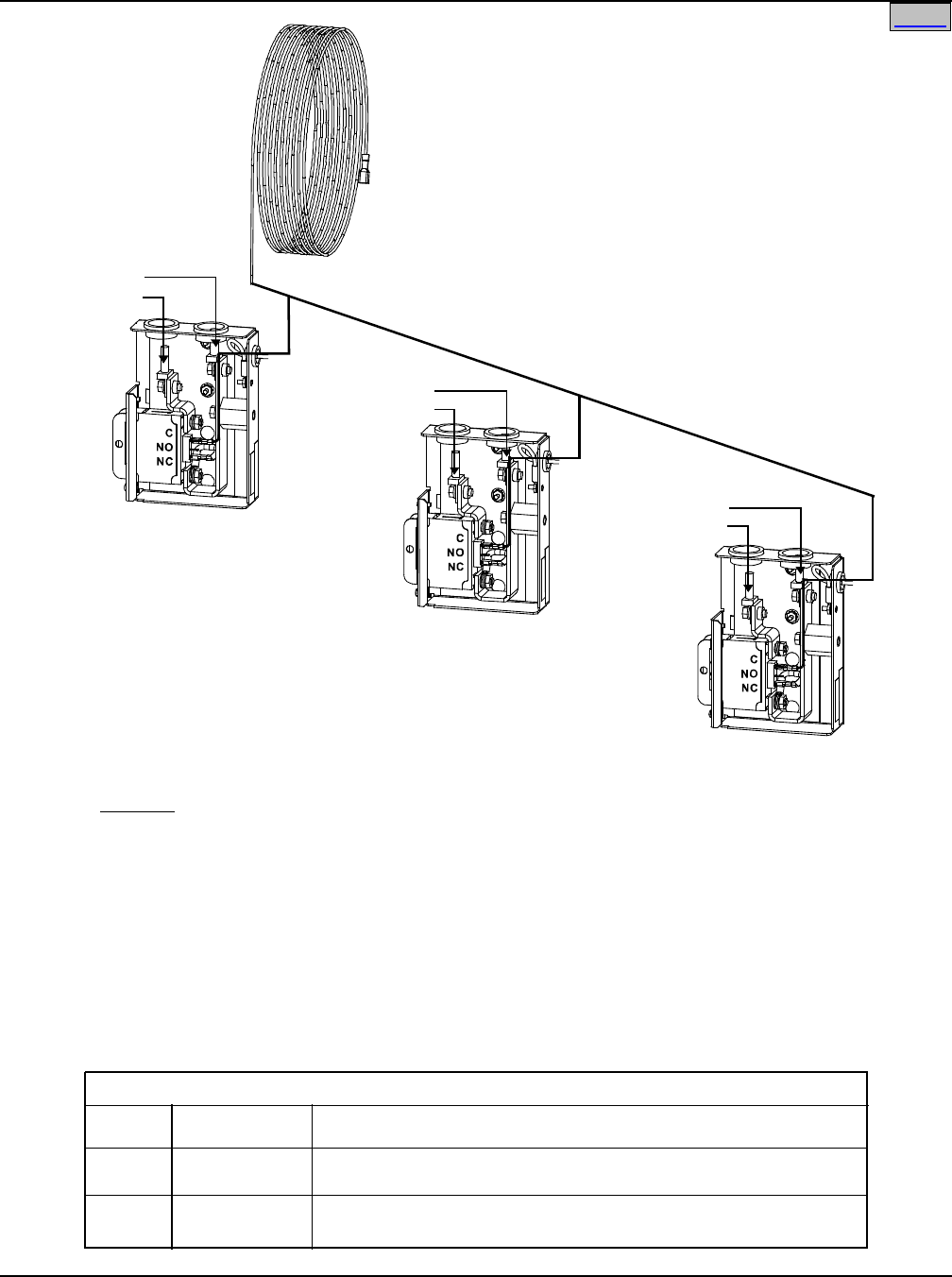
System Application Guide SAG582136600
Spec. No. 582136600 (Model 211NGFB) Issue AU, February 21, 2014
Page 77 of 105
This document is property of Emerson Network Power, Energy Systems, North America, Inc. and contains confidential and proprietary information owned by Emerson Network Power, Energy
Systems, North America, Inc. Any copying, use, or disclosure of it without the written permission of Emerson Network Power, Energy Systems, North America, Inc. is strictly prohibited.
Home Home
Yellow Jumper/Alarm
Lead (P/N 524384)
(Ordered separately
and supplied loose.
Must be wired
by the customer to
each circuit breaker
“C (Common)”
alarm terminal)
see
previous
page
Procedure
1. Connect kit-supplied YELLOW jumper/alarm lead
(P/N 524384) to circuit breaker “C (Common)”
alarm terminals on ALL Battery Disconnect Circuit
Breakers. Connect remaining per table below.
2. There is NO connection to the circuit
breaker “NO (Normally Open)”
alarm terminal.
1st BATTERY TRAY
BATTERY DISCONNECT
CIRCUIT BREAKER
Alarm Wiring to Battery Disconnect Circuit
Breakers when (1) to (3) Battery Trays are Used
(Side cover removed in illustration
to show wiring details.)
see
previous
page
see
previous
page
3. On ALL Battery Disconnect circuit
breakers, there should be a factory
connected Jumper connected from
the bottom terminal on the circuit
breaker to the circuit breaker “NC
(Normally Closed)” alarm terminal.
2nd BATTERY TRAY
BATTERY DISCONNECT
CIRCUIT BREAKER
(if furnished)
3rd BATTERY TRAY
BATTERY DISCONNECT
CIRCUIT BREAKER
(if furnished)
Connect to
shelf per
table below.
*
No terminal
on 524384
jumper
External Battery Disconnect Circuit Breaker Alarm Input:
A battery disconnect circuit breaker alarm is activated when the circuit
breaker is in the OFF position, and provides -48VDC to Digital Input # 2.
Must order Cable 545495
R-BK Lead of 545495. Splice and heat shrink tubing included with 545495
Pin 3 of J3 on customer interface BD (negative side of Digital Input # 2)
O-R Lead of 541311. Splice and heat shrink tubing included with 541311
NO
CONNECT YELLOW WIRE TO:
Alarm Cable
on shelf
YES
NO
YES
545495
541311
Shelf List
1 or 2
5 or 6
BREAKER ALARM CONNECTION
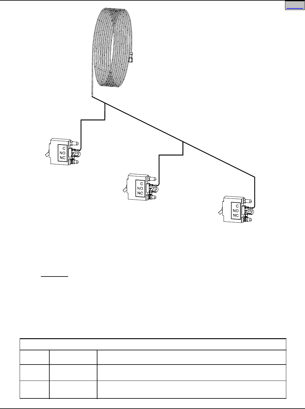
SAG582136600 System Application Guide
Issue AU, February 21, 2014 Spec. No. 582136600 (Model 211NGFB)
Page 78 of 105
This document is property of Emerson Network Power, Energy Systems, North America, Inc. and contains confidential and proprietary information owned by Emerson Network Power, Energy
Systems, North America, Inc. Any copying, use, or disclosure of it without the written permission of Emerson Network Power, Energy Systems, North America, Inc. is strictly prohibited.
Home
Yellow Jumper/Alarm
Lead (P/O Cabinet)
Orange Wire on
541434 not used
Procedure
1. Remove quick connect terminal from YELLOW
battery cabinet alarm lead.
2. Wire per table below.
1st BATTERY CABINET
BATTERY DISCONNECT
CIRCUIT BREAKER
Alarm Wiring to Battery Cabinets
alarm
wire
2nd BATTERY CABINET
BATTERY DISCONNECT
CIRCUIT BREAKER
3rd BATTERY CABINET
BATTERY DISCONNECT
CIRCUIT BREAKER
Connect to
shelf per
table below.
alarm
wire
alarm
wire
External Battery Disconnect Circuit Breaker Alarm Input:
A battery disconnect circuit breaker alarm is activated when the circuit
breaker is in the OFF position, and provides -48VDC to Digital Input # 2.
Must order Cable 545495
R-BK Lead of 545495. Splice and heat shrink tubing included with 545495
Pin 3 of J3 on customer interface BD (negative side of Digital Input # 2)
O-R Lead of 541311. Splice and heat shrink tubing included with 541311
NO
CONNECT YELLOW WIRE TO:
Alarm Cable
on shelf
YES
NO
YES
545495
541311
Shelf List
1 or 2
5 or 6
BREAKER ALARM CONNECTION
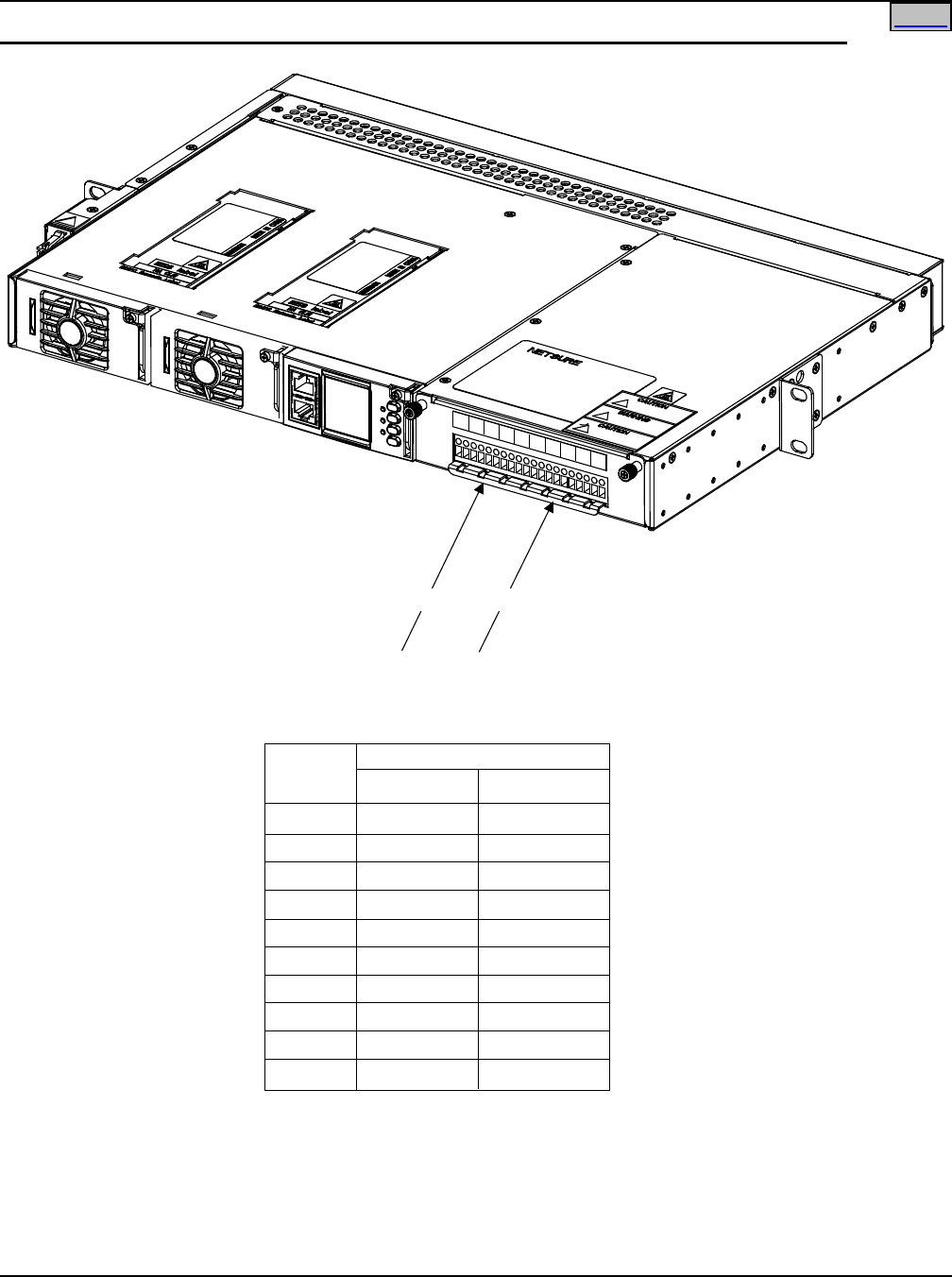
System Application Guide SAG582136600
Spec. No. 582136600 (Model 211NGFB) Issue AU, February 21, 2014
Page 79 of 105
This document is property of Emerson Network Power, Energy Systems, North America, Inc. and contains confidential and proprietary information owned by Emerson Network Power, Energy
Systems, North America, Inc. Any copying, use, or disclosure of it without the written permission of Emerson Network Power, Energy Systems, North America, Inc. is strictly prohibited.
Home
Load Distribution Wiring (GMT Fuses) (Lists BG and NG installed in a List 1 or 2, List 1 shown)
-48V Distribution
Leads
Load Return
Leads
Fuse
Position
Terminal
Load (-48V)Load Return
1
2
3
4
5
6
7
8
9
10
1
3
5
7
9
11
13
15
17
19
2
4
6
8
10
12
14
16
18
20
Connect to Front Terminal Block
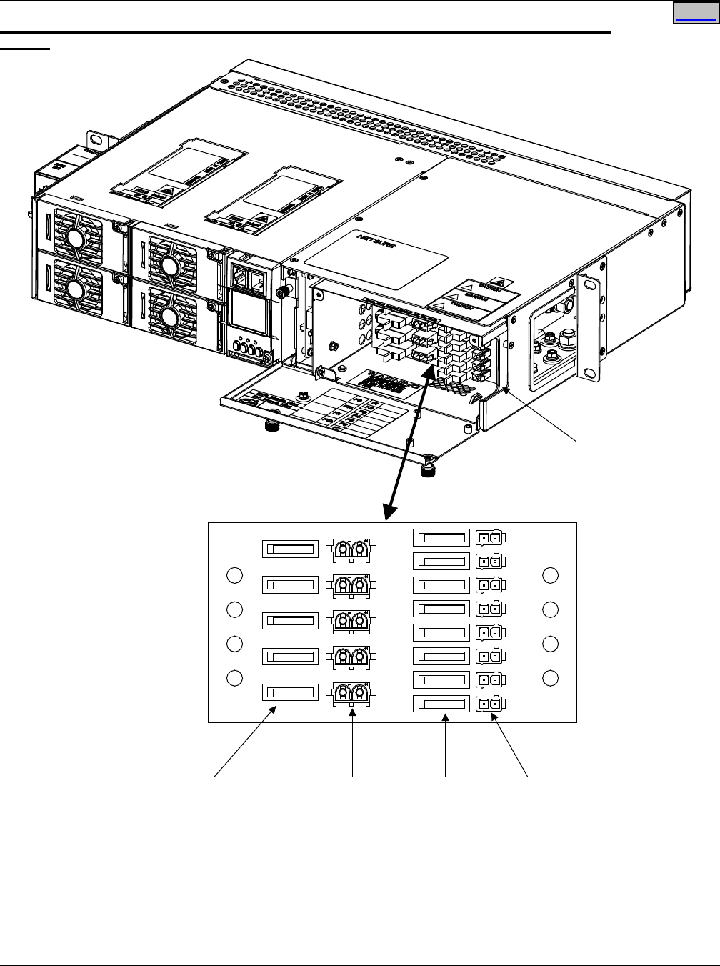
SAG582136600 System Application Guide
Issue AU, February 21, 2014 Spec. No. 582136600 (Model 211NGFB)
Page 80 of 105
This document is property of Emerson Network Power, Energy Systems, North America, Inc. and contains confidential and proprietary information owned by Emerson Network Power, Energy
Systems, North America, Inc. Any copying, use, or disclosure of it without the written permission of Emerson Network Power, Energy Systems, North America, Inc. is strictly prohibited.
Home
Load Distribution Wiring (GMT Fuses) (Lists BF, LF, and NF installed in a List 5 or 6, List 5
shown)
Front
Load Distribution
Leads Enter Here
Mating Connectors and 12'
Leads provided with List 62.
-48V on Left (Black Lead),
Return on Right (White Lead)
GMT Fuse
Positions
(Max. 15A)
GMT Fuse Load
Distribution Leads
Connect Here
GMT Fuse
Positions
(Max. 10A)
GMT Fuse Load
Distribution Leads
Connect Here
Mating Connectors and 12'
Leads provided with List 61.
-48V on Left (Black Lead),
Return on Right (White Lead)
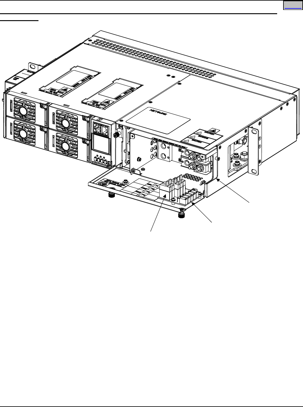
System Application Guide SAG582136600
Spec. No. 582136600 (Model 211NGFB) Issue AU, February 21, 2014
Page 81 of 105
This document is property of Emerson Network Power, Energy Systems, North America, Inc. and contains confidential and proprietary information owned by Emerson Network Power, Energy
Systems, North America, Inc. Any copying, use, or disclosure of it without the written permission of Emerson Network Power, Energy Systems, North America, Inc. is strictly prohibited.
Home
Load Distribution Wiring (GMT Fuses) (Lists BC, LC, NC, BA, LA, and NA installed in a List 5 or 6,
List 5 shown)
Mating Connectors and 12'
Leads provided with List 60.
-48V on Left (Black Lead),
Return on Right (White Lead);
as viewed from side with door
closed.
GMT Fuse Load
Distribution Leads
Connect Here
GMT Fuse
Positions
Front
Load Distribution
Leads Enter Here
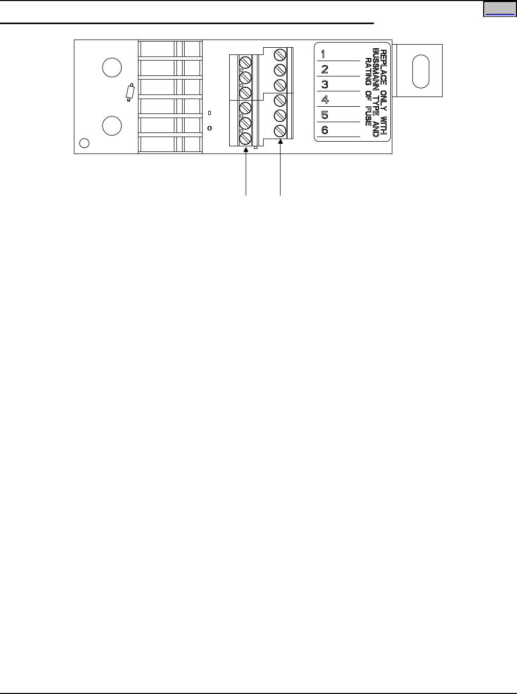
SAG582136600 System Application Guide
Issue AU, February 21, 2014 Spec. No. 582136600 (Model 211NGFB)
Page 82 of 105
This document is property of Emerson Network Power, Energy Systems, North America, Inc. and contains confidential and proprietary information owned by Emerson Network Power, Energy
Systems, North America, Inc. Any copying, use, or disclosure of it without the written permission of Emerson Network Power, Energy Systems, North America, Inc. is strictly prohibited.
Home
Load Distribution Wiring (Optional Bullet Nose 6-Position GMT Fuse Module)
-48V Distribution
Leads
Load Return
Leads
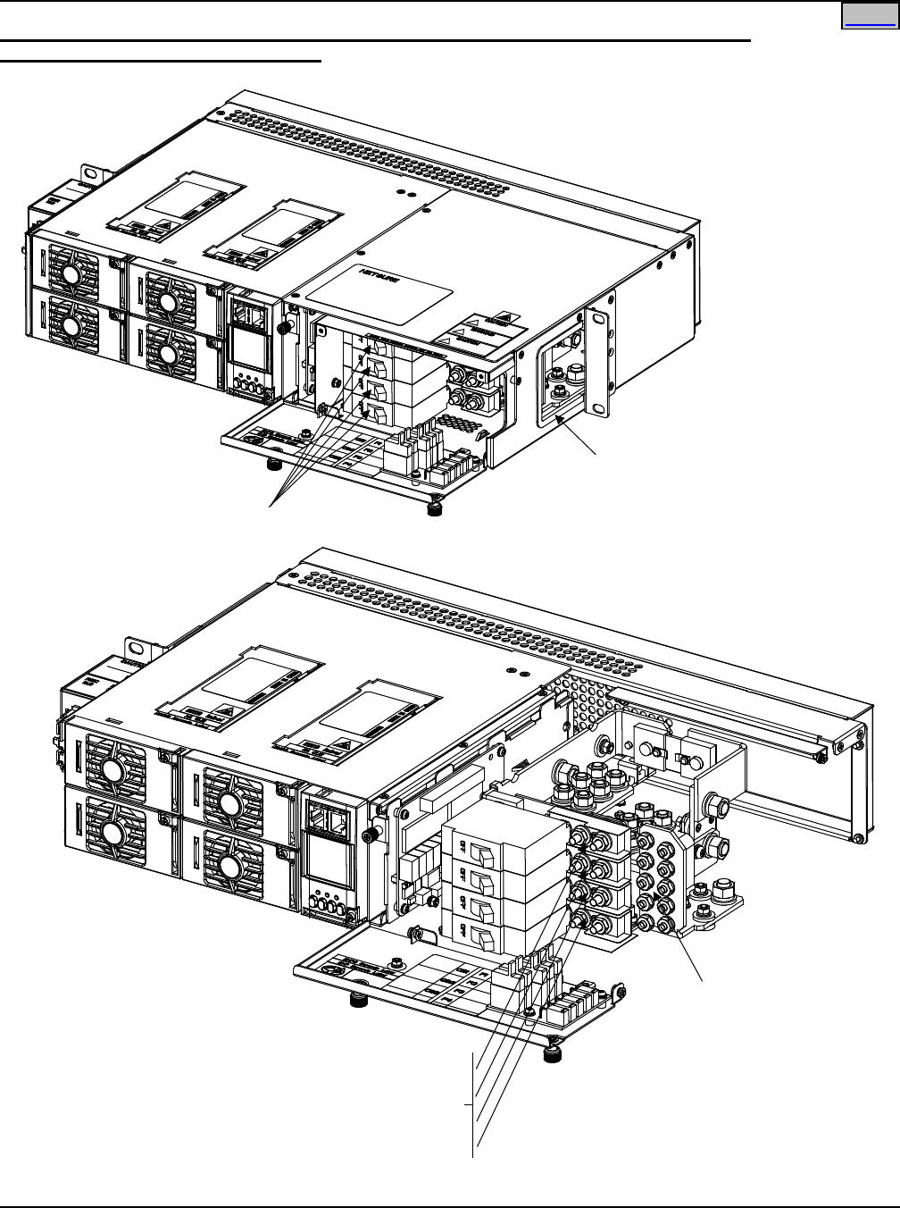
System Application Guide SAG582136600
Spec. No. 582136600 (Model 211NGFB) Issue AU, February 21, 2014
Page 83 of 105
This document is property of Emerson Network Power, Energy Systems, North America, Inc. and contains confidential and proprietary information owned by Emerson Network Power, Energy
Systems, North America, Inc. Any copying, use, or disclosure of it without the written permission of Emerson Network Power, Energy Systems, North America, Inc. is strictly prohibited.
Home
Load Distribution Wiring (Circuit Breakers) and CO Ground Wiring (Lists BC, LC, and NC
installed in a List 5 or 6, List 5 shown)
Front
Circuit Breaker Load
Distribution and
CO Ground Leads
Enter Here
Load Distribution
Circuit Breakers
Front
Portion of shelf removed
in illustration for clarity.
Leads are brought into
side of shelf, and tools
to secure lugs from
front of shelf. -48V Load
Distribution
Leads
Load Return Leads
CO Ground Lead
10-32 studs (w/ hardware)
on 5/8" centers for installation
of customer provided two hole lugs.
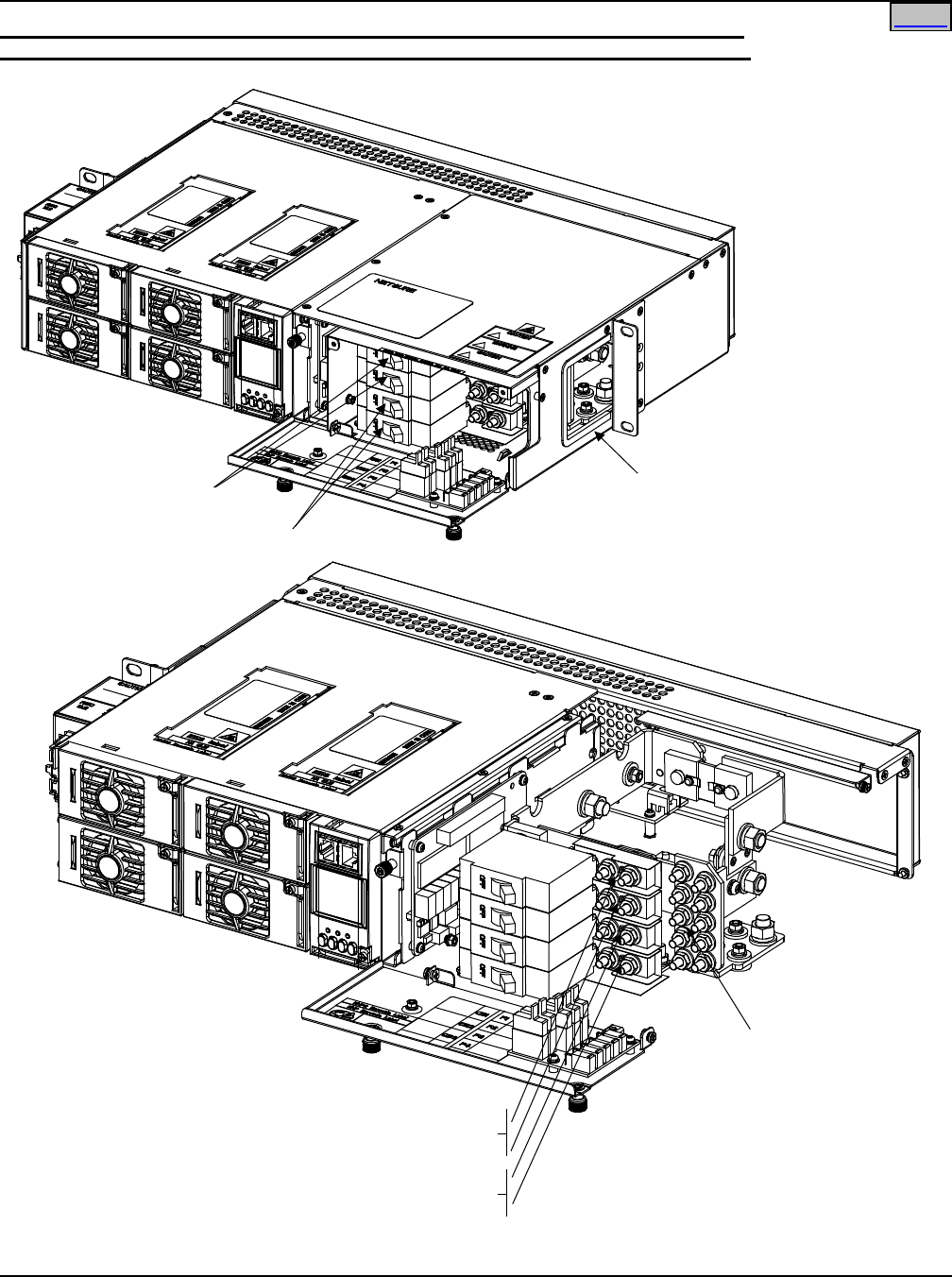
SAG582136600 System Application Guide
Issue AU, February 21, 2014 Spec. No. 582136600 (Model 211NGFB)
Page 84 of 105
This document is property of Emerson Network Power, Energy Systems, North America, Inc. and contains confidential and proprietary information owned by Emerson Network Power, Energy
Systems, North America, Inc. Any copying, use, or disclosure of it without the written permission of Emerson Network Power, Energy Systems, North America, Inc. is strictly prohibited.
Home
Load Distribution Wiring (Circuit Breakers), Input Battery Wiring (Circuit Breakers),
and CO Ground Wiring (Lists BA, LA, and NA installed in a List 5 or 6, List 5 shown)
CO Ground, Circuit Breaker
Load Distribution, and Circuit
Breaker Battery Leads
Enter Here
Battery Disconnect
Circuit Breakers
-48V Battery
Leads
-48V Load
Distribution
Leads
Battery Return Leads
Load Return Leads
CO Ground Lead
OBSERVE PROPER
POLARITY WHEN
MAKING BATTERY
CONNECTIONS
Front
Load Distribution
Circuit Breakers
Front
Portion of shelf removed
in illustration for clarity.
Leads are brought into
side of shelf, and tools
to secure lugs from
front of shelf.
10-32 studs (w/ hardware)
on 5/8" centers for installation
of customer provided two hole lugs.
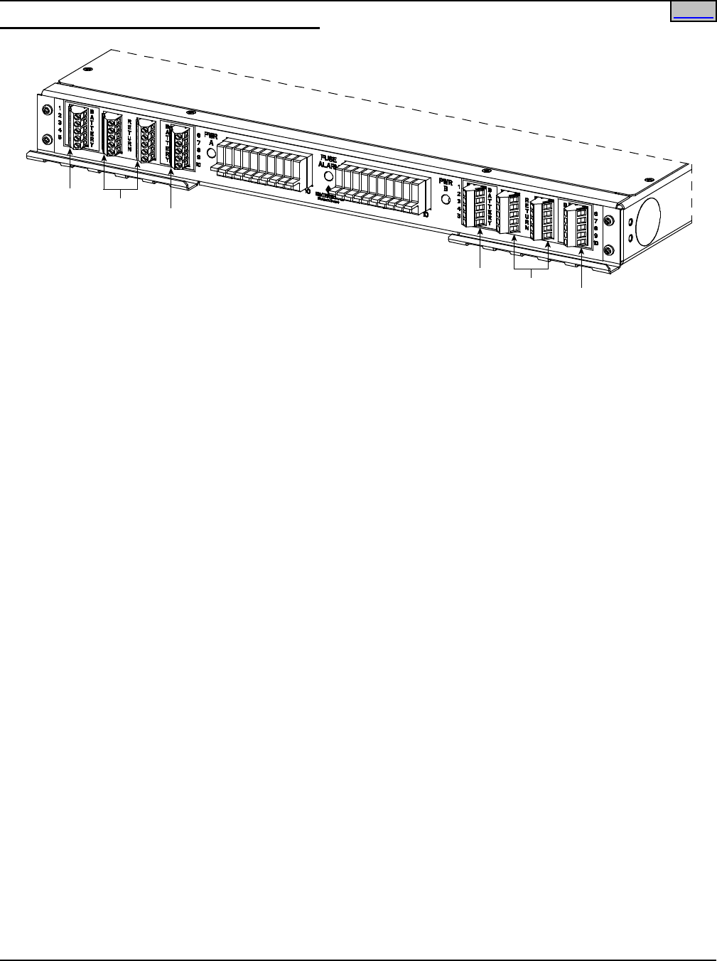
System Application Guide SAG582136600
Spec. No. 582136600 (Model 211NGFB) Issue AU, February 21, 2014
Page 85 of 105
This document is property of Emerson Network Power, Energy Systems, North America, Inc. and contains confidential and proprietary information owned by Emerson Network Power, Energy
Systems, North America, Inc. Any copying, use, or disclosure of it without the written permission of Emerson Network Power, Energy Systems, North America, Inc. is strictly prohibited.
Load Distribution Wiring (GMT Fuses) (List KG)
“A” Side Loads #1 - #5
“A” Side Loads #6 - #10
“A” Side Returns
“B” Side Loads #1 - #5
“B” Side Loads #6 - #10
“B” Side Returns
Connections aremade to
screw compression terminal blocks.
Wire size range is 26 to 14 AWG.
Inputs for Side “A” and Side “B”
are strapped in this system.
Home
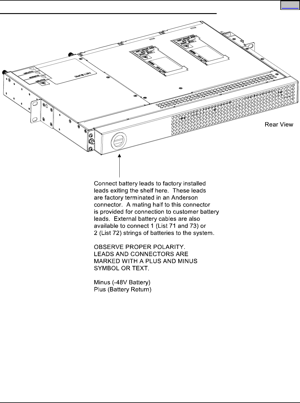
SAG582136600 System Application Guide
Issue AU, February 21, 2014 Spec. No. 582136600 (Model 211NGFB)
Page 86 of 105
This document is property of Emerson Network Power, Energy Systems, North America, Inc. and contains confidential and proprietary information owned by Emerson Network Power, Energy
Systems, North America, Inc. Any copying, use, or disclosure of it without the written permission of Emerson Network Power, Energy Systems, North America, Inc. is strictly prohibited.
Home
Input Battery Wiring (Lists BG and NG installed in a List 1 or 2, List 1 shown)
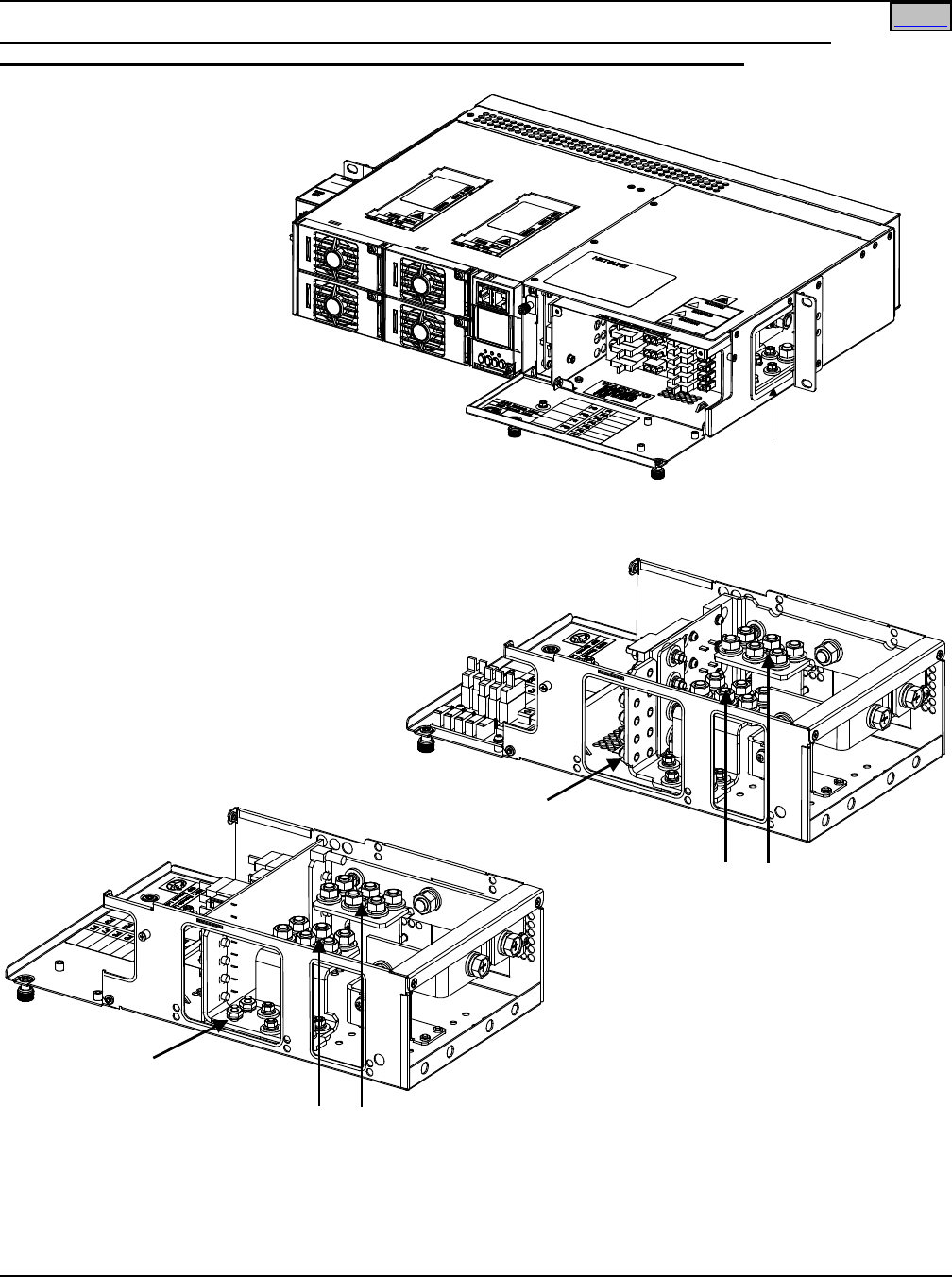
System Application Guide SAG582136600
Spec. No. 582136600 (Model 211NGFB) Issue AU, February 21, 2014
Page 87 of 105
This document is property of Emerson Network Power, Energy Systems, North America, Inc. and contains confidential and proprietary information owned by Emerson Network Power, Energy
Systems, North America, Inc. Any copying, use, or disclosure of it without the written permission of Emerson Network Power, Energy Systems, North America, Inc. is strictly prohibited.
Home
Input Battery Wiring (Lists BF, LF, NF, BC, LC, and NC installed in a List 1 or 5, List 5 shown)
and CO Ground Wiring (Lists BF, LF, and NF installed in a List 1 or 5, List 5 shown)
List NF Distribution
Unit shown. List BF,
LF, BC, LC, and NC similar.
Front
Battery, Battery Return,
and CO Ground Leads
Enter Here
Distribution
Unit
List 65 provides 3' long, 2 AWG, battery cables
terminated on one end with lugs to connect to
the input battery landings and on the other end
with an Anderson connector.
List 66 provides 12' long, 2 AWG, battery cables
terminated on one end in an Anderson connector
and left unterminated at the remaining end for
connection of battery lugs.
Battery: 1/4-20 studs (w/hardware)
on 5/8" centers for installation
of customer provided two hole lugs.
CO Ground: 10-32 studs (w/hardware)
on 5/8" centers for installation
of customer provided two hole lugs.
OBSERVE PROPER
POLARITY WHEN
MAKING BATTERY
CONNECTIONS
Right Side
-48 Battery Leads
Battery Return Leads
CO Ground Lead
CO Ground Lead
List BF, LF, and NF
Distribution Unit
List BC, LC, and NC
Distribution Unit
-48 Battery Leads
Battery Return Leads
Right Side

SAG582136600 System Application Guide
Issue AU, February 21, 2014 Spec. No. 582136600 (Model 211NGFB)
Page 88 of 105
This document is property of Emerson Network Power, Energy Systems, North America, Inc. and contains confidential and proprietary information owned by Emerson Network Power, Energy
Systems, North America, Inc. Any copying, use, or disclosure of it without the written permission of Emerson Network Power, Energy Systems, North America, Inc. is strictly prohibited.
Home
SPECIFICATIONS
Note: For all rectifier specifications, refer to the separate Rectifier User Manual (UM1R48500/UM1R481000)
supplied with your Power System.
For all controller specifications, refer to the Controller User Manual (UM1M521B or UM1M820B)
supplied with your Power System.
For factory settings of all configurable Controller parameters, refer to the Configuration Drawing (C-
drawing) supplied with your Power System.
1. SYSTEM
1.1 Environmental Ratings
1.1.1 Operating Ambient Temperature Range (Specification Compliant):
(A) -40°C (-40°F) to +65°C (+149°F) with derating output.
(B) -40°C (-40°F) to +40°C (+104°F) with full power performance.
1.1.2 Storage Ambient Temperature Range: -40°C (-40°F) to +75°C (+167°F).
1.1.3 Humidity: This Power System is capable of operating in an ambient relative humidity range of
0% to 90%, non-condensing.
1.1.4 Altitude: 2000 m (6560 ft) at full power (power limited for heights above 2000 m).
1.1.5 Mounting: This product is intended only for installation in a Restricted Access Location on or
above a non-combustible surface.
This product must be located in a Controlled Environment with access to Craftspersons only.
This product is intended for installation in Network Telecommunication Facilities (CO, vault, hut,
or other environmentally controlled electronic equipment enclosure).
This product is intended to be connected to the common bonding network in a Network
Telecommunication Facility (CO, vault, hut, or other environmentally controlled electronic
equipment enclosure).
Typical industry standards recommend minimum aisle space clearance of 2'6" for the front of the
relay rack and 2' for the rear of the relay rack.
Separate shelves are available for mounting in either a 19" or 23" wide relay rack (1” or 1-3/4”
multiple drillings for the 2U shelf and 1-3/4" multiple drillings for the 1U shelf).
Mounting angles are positioned for a 5-inch front projection mounting only.
Flush mounting is done using optional kits.
1.1.6 Ventilation Requirements: Rectifier and mounting shelf ventilating openings must not be
blocked and temperature of air entering rectifiers must not exceed rated Operating Ambient
Temperature Range stated above.
1.2 Compliance Information
1.2.1 Surge Protection: Refer to Paragraphs 2.3.6. and 3.3.6.
Note: This level of protection is a widely used standard for telecommunications power
equipment. As with all such equipment, it is the end user's responsibility to provide an
adequately sized Surge Suppression Device at the commercial power service entrance of
the building that reduces all incoming surges to levels below the classes/categories
stated for the equipment.
1.2.2 Safety Compliance:
(A) This unit meets the requirements of UL 60950, Standard for Information Technology
Equipment, and is UL Recognized as a power supply for use in Telephone, Electronic Data
Processing, or Information Processing Equipment.
(B) This unit meets the requirements of CAN/CSA 22.2, No. 60950-00 and is tested and
Certified by UL ("c UR") as a Component Type Power Supply.
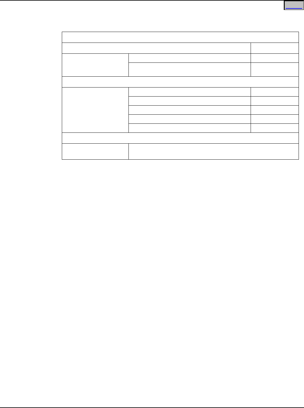
System Application Guide SAG582136600
Spec. No. 582136600 (Model 211NGFB) Issue AU, February 21, 2014
Page 89 of 105
This document is property of Emerson Network Power, Energy Systems, North America, Inc. and contains confidential and proprietary information owned by Emerson Network Power, Energy
Systems, North America, Inc. Any copying, use, or disclosure of it without the written permission of Emerson Network Power, Energy Systems, North America, Inc. is strictly prohibited.
Home
Home
1.2.3 EMC and Safety:
(A) Complies with the Low-Voltage Directive, 73/23/EEC. Complies with Emissions
and Immunity requirements as specified in GR-1089-Core Issue 4.
EMC
Emissions Test Level
EN 55022: 1998
CFR 47 – Part 15
GR-1089 Issue 4
Conducted
Class B
Radiated Class B
Immunity
GR-1089 Issue 4
EN 61000-4-2 Electrostatic Discharge 8kV / 15kV
EN 61000-4-4 Electric Fast Transients 0.25kV / 0.5kV
Radiated Immunity 8.5V/m
Conducted Immunity 89dBuA
Surge IEEE C62.41 2kV / 6kV
SAFETY
EN 60950-1: 2001 Safety of Information Technology Equipment, including
Electrical Business Equipment
1.2.4 NEBS Compliance: Compliance verified by a Nationally Recognized Testing Laboratory
(NRTL) per GR-1089-CORE and GR-63-CORE. Contact Emerson Network Power for NEBS
compliance reports.
For NETSURE™ 211NGFB to remain compliant during a fan failure condition, the backup battery
connection must be utilized to provide sufficient power to the loads for up to eight (8) hours
when the system is operated at greater than 50% output power. If no backup battery
connection is used, the system must operate with a redundant module installed.
1.3 Standard Features
1.3.1 AC Input Connections: AC input cable assemblies and line cords are available.
(A) List 1 and 2: Mounted to the side of the shelf is an AC input housing with one (1) plug-in
connector for one (1) AC input feed.
(B) List 5 and 6: Mounted to the side of the shelf is an AC input housing with two (2) plug-in
connectors for two (2) AC input feeds.
1.3.2 Battery Connections: Battery cables are available.
(A) List 1 and 2: Battery leads are connected to an Anderson connector exiting the rear of the
unit.
(B) Lists 5 and 6: Battery and battery return leads terminated in two-hole lugs are connected to
threaded studs located inside the Distribution Unit. Battery leads are brought into the right
side (as viewed from the front) of the shelf.
1.3.3 Load Connections:
(A) List 1 and 2: Load and load return leads are connected to a screw-type terminal block
located on the front of the shelf.
(B) Lists 5 and 6: Load distribution (circuit breakers, if furnished) and load return leads
terminated in two-hole lugs are connected to threaded studs located inside the Distribution
Unit. Load leads are brought into the right side (as viewed from the front) of the shelf and
are accessible from the front of the shelf.

SAG582136600 System Application Guide
Issue AU, February 21, 2014 Spec. No. 582136600 (Model 211NGFB)
Page 90 of 105
This document is property of Emerson Network Power, Energy Systems, North America, Inc. and contains confidential and proprietary information owned by Emerson Network Power, Energy
Systems, North America, Inc. Any copying, use, or disclosure of it without the written permission of Emerson Network Power, Energy Systems, North America, Inc. is strictly prohibited.
Load distribution (GMT fuses) and load return leads are connected to receptacles located
inside the Distribution Unit. Load leads are brought into the right side (as viewed from the
front) of the shelf and are accessible from the front of the shelf.
1.3.4 Alarm and Monitoring Connections: Customer wiring cables are available.
(A) List 1 and 2: Relay output and digital input leads are connected to screw-type terminal
blocks located on the SCU+ located inside the shelf. These leads enter the rear of the shelf.
(B) Lists 5 and 6: Relay output and digital input leads are connected to screw-type terminal
blocks located on the Customer Interface Board located inside the shelf. These leads enter
the right side (as viewed from the front) of the shelf and are accessible from the front of the
shelf.
1.3.5 Dimensions and Weights: Refer to the PHYSICAL SIZE INFORMATION section of this
document.
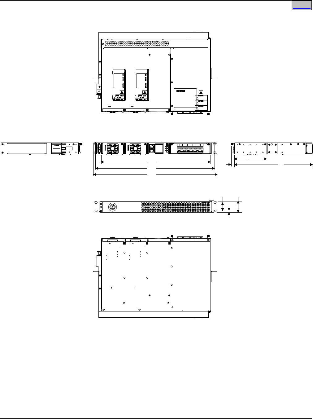
System Application Guide SAG582136600
Spec. No. 582136600 (Model 211NGFB) Issue AU, February 21, 2014
Page 91 of 105
This document is property of Emerson Network Power, Energy Systems, North America, Inc. and contains confidential and proprietary information owned by Emerson Network Power, Energy
Systems, North America, Inc. Any copying, use, or disclosure of it without the written permission of Emerson Network Power, Energy Systems, North America, Inc. is strictly prohibited.
Home
PHYSICAL SIZE INFORMATION
Overall Dimensions – List 1
T
op View
Front View
Rear View
Left Side View
Right Side View
5
12
Bottom View
Notes:
1. All dimensions are in inches,
unless otherwise specified.
2. Weight in LBS.
Net: 16
Shipping:
3. Finish: Front Panels are Gray
Shelf is Galvaneal.
17.3
0.23
1.721.25
18.3
19.0
0.5
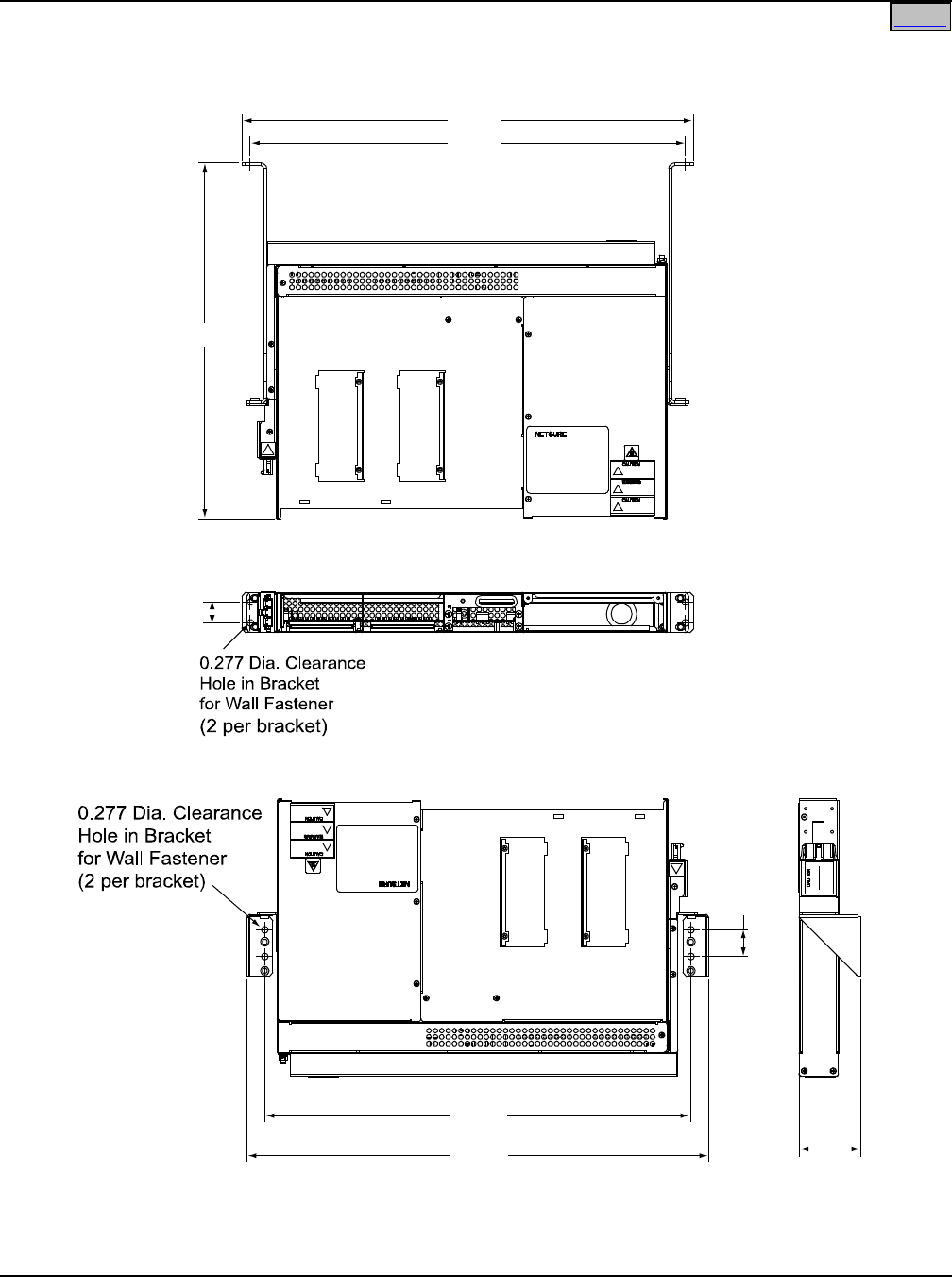
SAG582136600 System Application Guide
Issue AU, February 21, 2014 Spec. No. 582136600 (Model 211NGFB)
Page 92 of 105
This document is property of Emerson Network Power, Energy Systems, North America, Inc. and contains confidential and proprietary information owned by Emerson Network Power, Energy
Systems, North America, Inc. Any copying, use, or disclosure of it without the written permission of Emerson Network Power, Energy Systems, North America, Inc. is strictly prohibited.
Home
Additional Dimensions – List 1 with Wall Mounting Kit (P/N 541285)
Top View Right Side
View
Vertical Wall Mounting
1.15
18.38
19.87 2.65
Top View
Rear View
Horizontal Wall Mounting
0.90
19.45
18.72
15.34
Note: All dimensions are in inches.
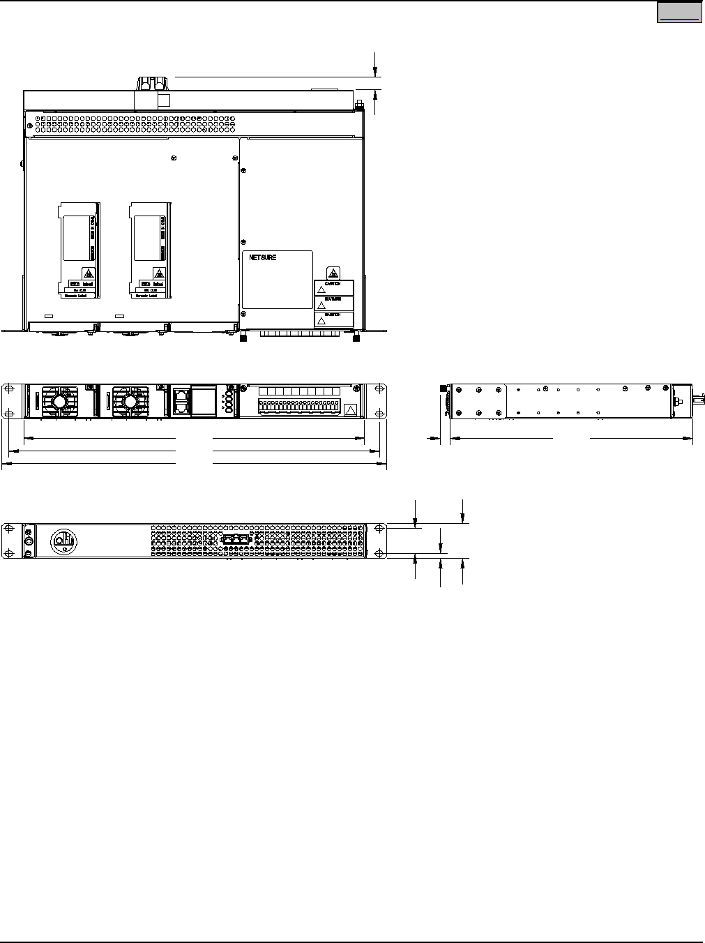
System Application Guide SAG582136600
Spec. No. 582136600 (Model 211NGFB) Issue AU, February 21, 2014
Page 93 of 105
This document is property of Emerson Network Power, Energy Systems, North America, Inc. and contains confidential and proprietary information owned by Emerson Network Power, Energy
Systems, North America, Inc. Any copying, use, or disclosure of it without the written permission of Emerson Network Power, Energy Systems, North America, Inc. is strictly prohibited.
Home
Additional Dimensions – List 1 with Optional 19” Rear Cover Kit, P/N 555260
16.9
18.3
19.0
Right Side View
0.5 12.0
0.6
1.25 1.75
0.25
Rear View
Front View
Top View
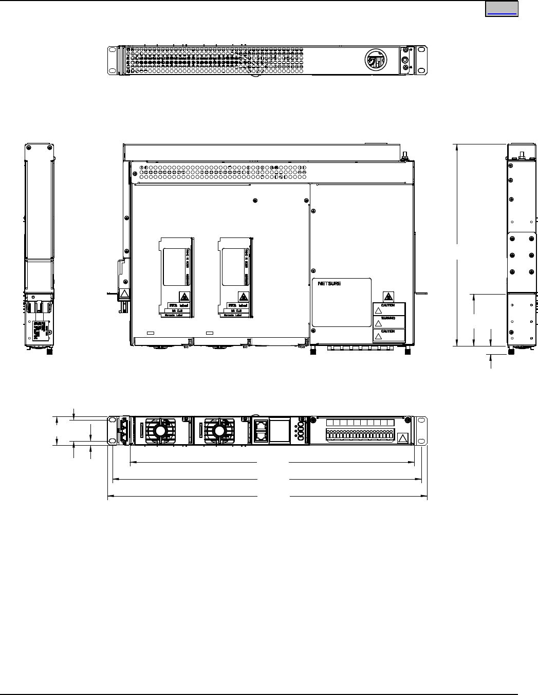
SAG582136600 System Application Guide
Issue AU, February 21, 2014 Spec. No. 582136600 (Model 211NGFB)
Page 94 of 105
This document is property of Emerson Network Power, Energy Systems, North America, Inc. and contains confidential and proprietary information owned by Emerson Network Power, Energy
Systems, North America, Inc. Any copying, use, or disclosure of it without the written permission of Emerson Network Power, Energy Systems, North America, Inc. is strictly prohibited.
Home
Additional Dimensions – List 1 with Optional 3” Projection Mount Kit, P/N 556828
Rear View
Left Side
View
Right Side
View
Top View
Front View
12
3
0.5
1.25
1.71
0.24 16.9
18.3
19.0
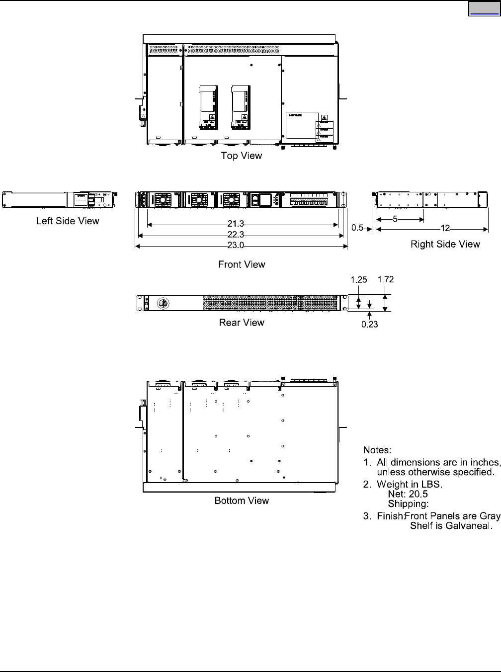
System Application Guide SAG582136600
Spec. No. 582136600 (Model 211NGFB) Issue AU, February 21, 2014
Page 95 of 105
This document is property of Emerson Network Power, Energy Systems, North America, Inc. and contains confidential and proprietary information owned by Emerson Network Power, Energy
Systems, North America, Inc. Any copying, use, or disclosure of it without the written permission of Emerson Network Power, Energy Systems, North America, Inc. is strictly prohibited.
Home
Overall Dimensions – List 2
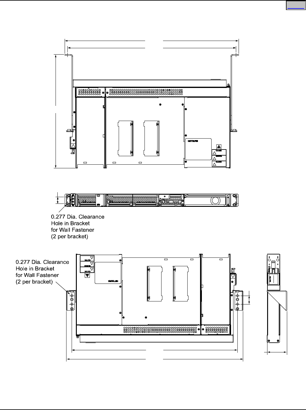
SAG582136600 System Application Guide
Issue AU, February 21, 2014 Spec. No. 582136600 (Model 211NGFB)
Page 96 of 105
This document is property of Emerson Network Power, Energy Systems, North America, Inc. and contains confidential and proprietary information owned by Emerson Network Power, Energy
Systems, North America, Inc. Any copying, use, or disclosure of it without the written permission of Emerson Network Power, Energy Systems, North America, Inc. is strictly prohibited.
Home
Additional Dimensions – List 2 with Wall Mounting Kit (P/N 541285)
Note: All dimensions are in inches.
Top View
Rear View
Horizontal Wall Mounting
23.41
22.69
Top View
Vertical Wall Mounting
22.34
23.83
Right Side
View
2.65
1.15
15.34
0.90
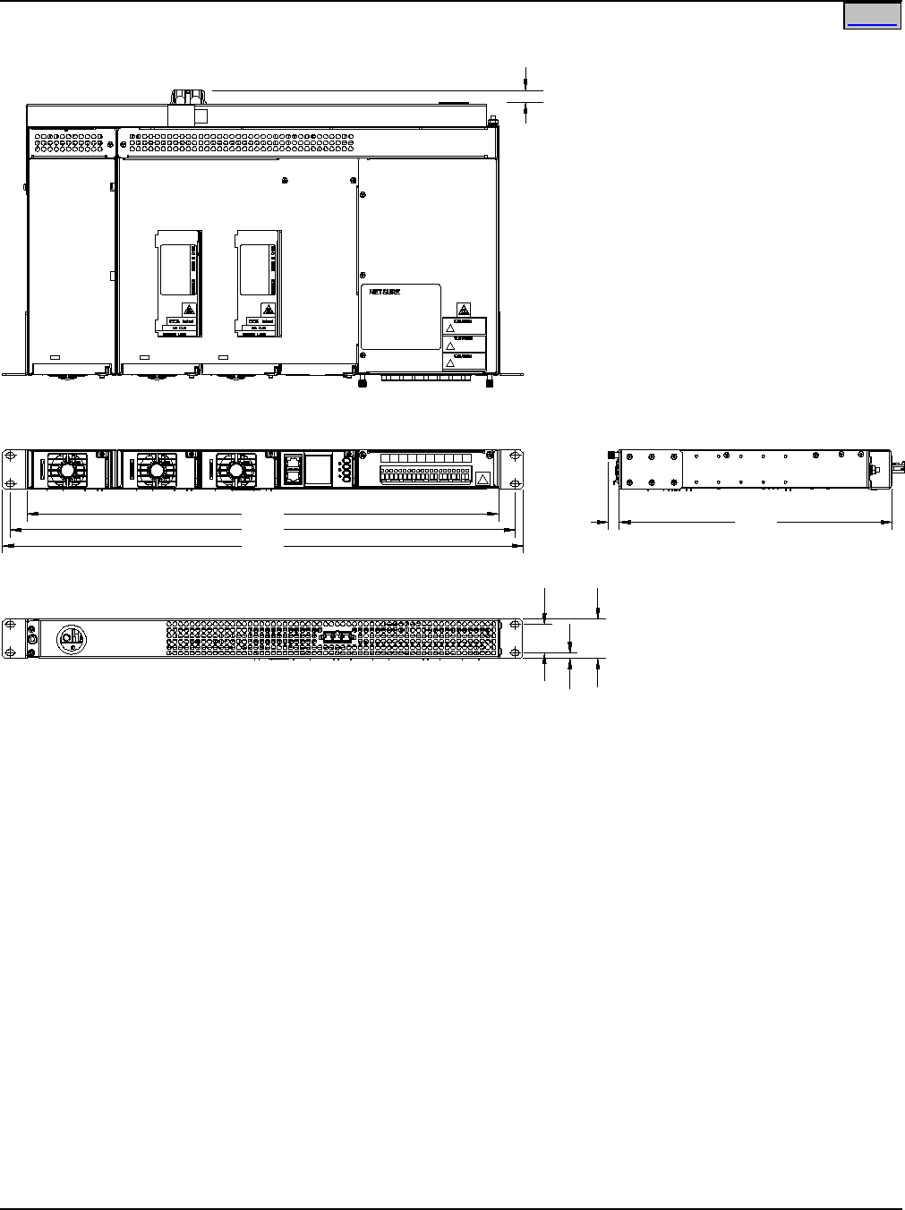
System Application Guide SAG582136600
Spec. No. 582136600 (Model 211NGFB) Issue AU, February 21, 2014
Page 97 of 105
This document is property of Emerson Network Power, Energy Systems, North America, Inc. and contains confidential and proprietary information owned by Emerson Network Power, Energy
Systems, North America, Inc. Any copying, use, or disclosure of it without the written permission of Emerson Network Power, Energy Systems, North America, Inc. is strictly prohibited.
Home
Additional Dimensions – List 2 with Optional 23” Rear Cover Kit, P/N 555261
20.8
22.3
23.0
Right Side View
0.5 12.0
0.6
1.25 1.75
0.25
Rear View
Front View
Top View
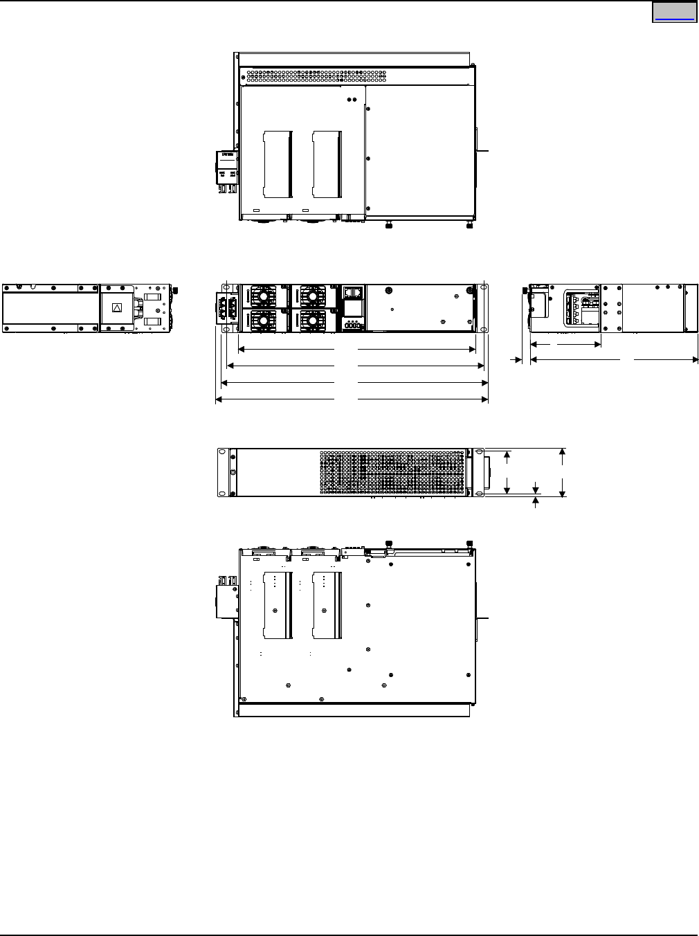
SAG582136600 System Application Guide
Issue AU, February 21, 2014 Spec. No. 582136600 (Model 211NGFB)
Page 98 of 105
This document is property of Emerson Network Power, Energy Systems, North America, Inc. and contains confidential and proprietary information owned by Emerson Network Power, Energy
Systems, North America, Inc. Any copying, use, or disclosure of it without the written permission of Emerson Network Power, Energy Systems, North America, Inc. is strictly prohibited.
Home
Overall Dimensions – List 5
TopView
Front View
Rear View
Bottom View
Left Side View
Right Side View
18.3
19.0
17.3 5
12
19.4
Notes:
1. All dimensions are in inches,
unless otherwise specified.
2. Weight in LBS.
Net: 30
Shipping:
3. Finish: Front Panels are Gray
Shelf is Galvaneal.
0.23
3.46
3.00
0.5
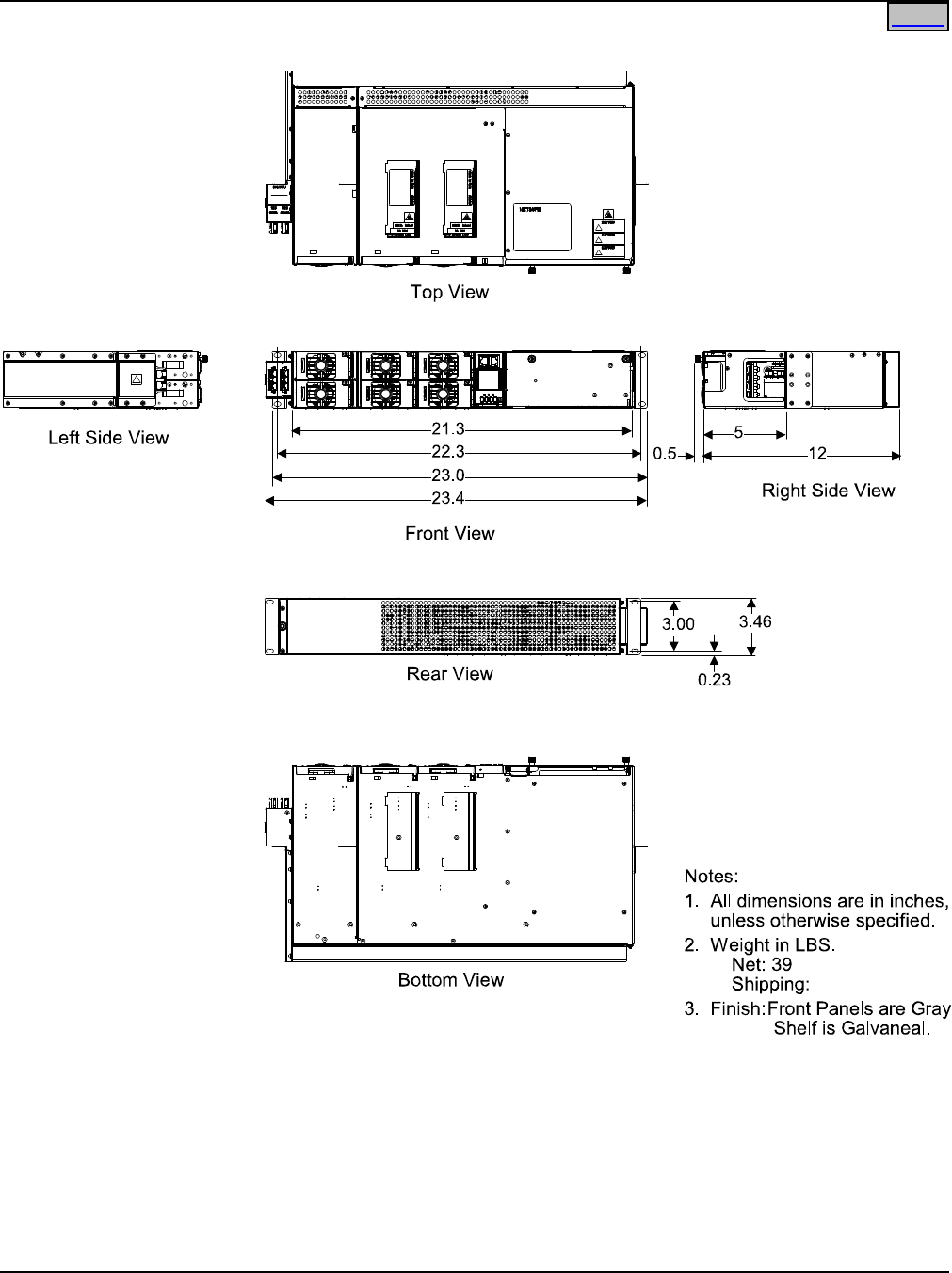
System Application Guide SAG582136600
Spec. No. 582136600 (Model 211NGFB) Issue AU, February 21, 2014
Page 99 of 105
This document is property of Emerson Network Power, Energy Systems, North America, Inc. and contains confidential and proprietary information owned by Emerson Network Power, Energy
Systems, North America, Inc. Any copying, use, or disclosure of it without the written permission of Emerson Network Power, Energy Systems, North America, Inc. is strictly prohibited.
Home
Overall Dimensions – List 6
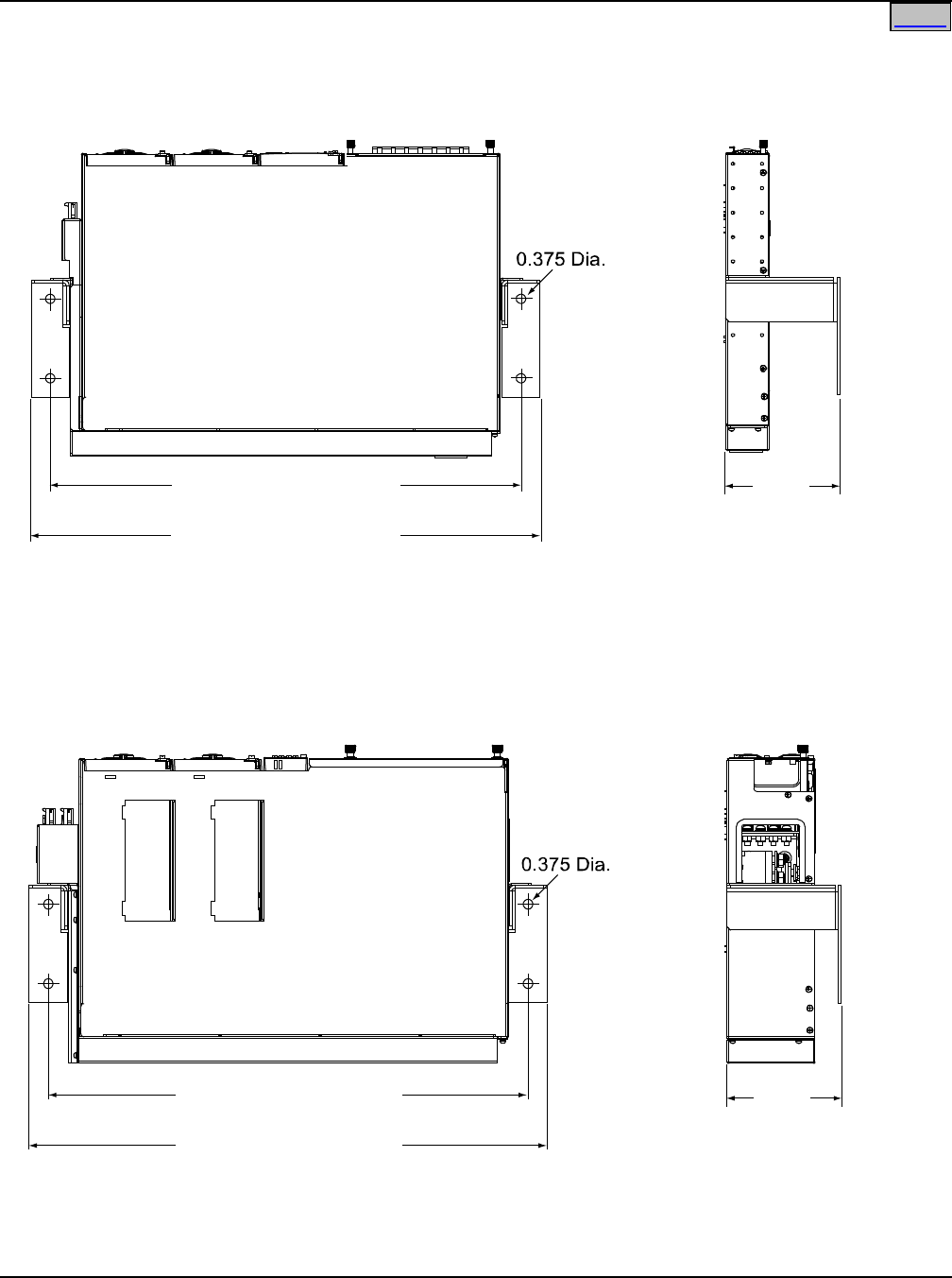
SAG582136600 System Application Guide
Issue AU, February 21, 2014 Spec. No. 582136600 (Model 211NGFB)
Page 100 of 105
This document is property of Emerson Network Power, Energy Systems, North America, Inc. and contains confidential and proprietary information owned by Emerson Network Power, Energy
Systems, North America, Inc. Any copying, use, or disclosure of it without the written permission of Emerson Network Power, Energy Systems, North America, Inc. is strictly prohibited.
Home
Additional Dimensions – Lists 1, 2, 5 and 6 with Wall Mounting Kit (P/N 553203)
Lists 1 and 2
Lists 5 and 6
Note: All dimensions are in inches.
Bottom View
18.936 (19” Shelf, shown)
22.906 (23” Shelf)
20.543 (19”, shown Shelf)
24.513 (23” Shelf)
Right Side View
4.625
Bottom View
18.936 (19” Shelf, shown)
22.906 (23” Shelf)
20.543 (19” Shelf, shown)
24.513 (23” Shelf)
Right Side View
4.625
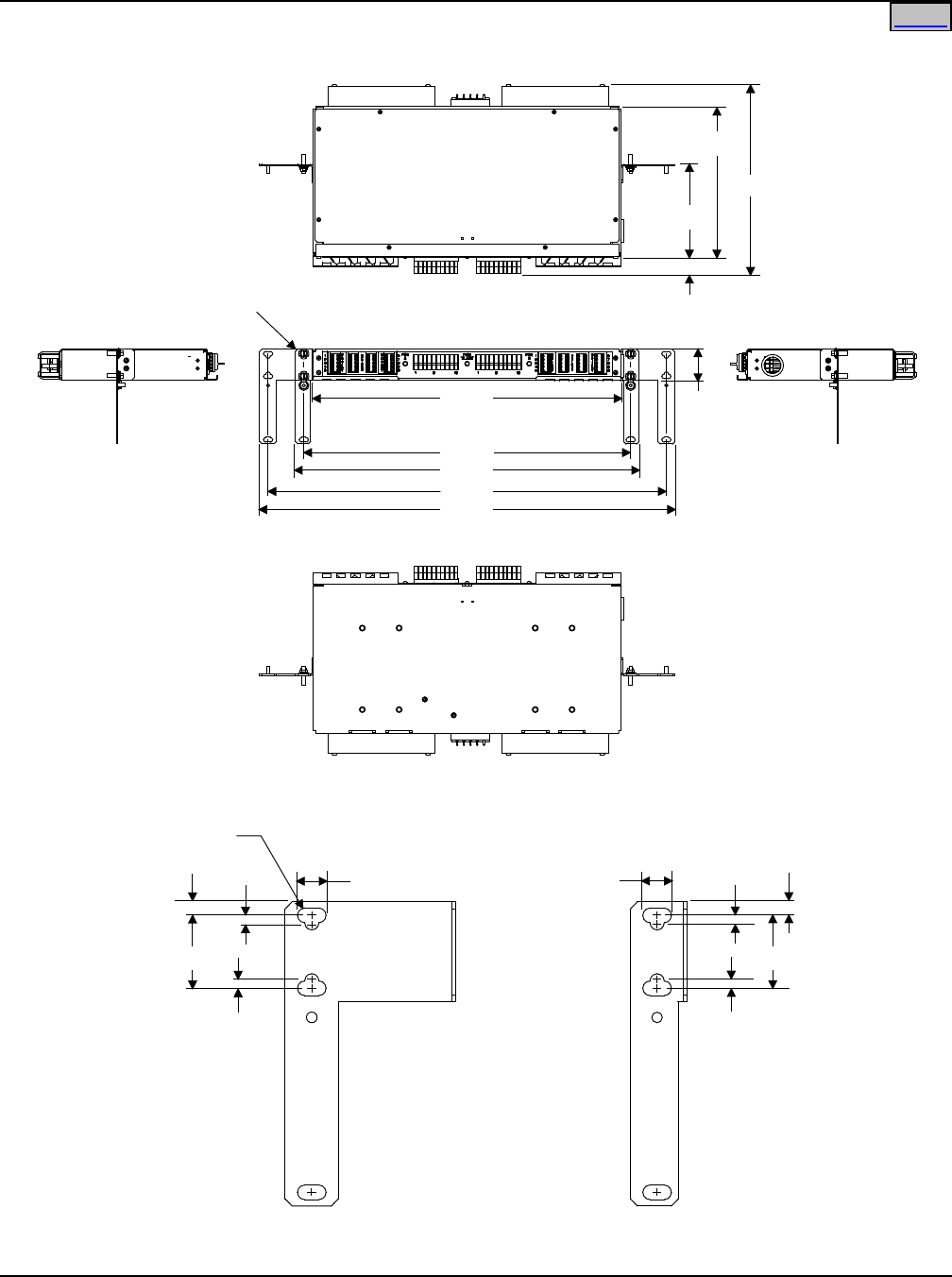
System Application Guide SAG582136600
Spec. No. 582136600 (Model 211NGFB) Issue AU, February 21, 2014
Page 101 of 105
This document is property of Emerson Network Power, Energy Systems, North America, Inc. and contains confidential and proprietary information owned by Emerson Network Power, Energy
Systems, North America, Inc. Any copying, use, or disclosure of it without the written permission of Emerson Network Power, Energy Systems, North America, Inc. is strictly prohibited.
Home
Overall Dimensions – List KG
Bottom View
See Mounting
Angle Detail
Left Side
View
Right Side
View
Top View
5.05
10.00
8.31
0.92
Front View
17.25
18.25
19.25
22.31
23.25
1.75
Notes:
1. Dimensions in inches
unless otherwise specified.
2. Finish: Gray
3. Weight:
Net:
Shipping:
Mounting Angle Detail
1.250
0.500 0.125 0.235
0.125
R 0.125 (TYP)
1.250
0.500
0.125
0.235
0.125
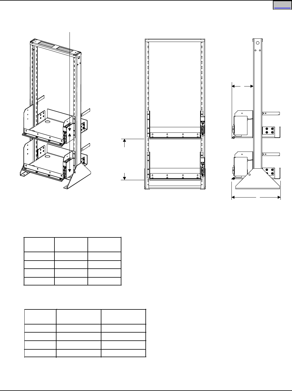
SAG582136600 System Application Guide
Issue AU, February 21, 2014 Spec. No. 582136600 (Model 211NGFB)
Page 102 of 105
This document is property of Emerson Network Power, Energy Systems, North America, Inc. and contains confidential and proprietary information owned by Emerson Network Power, Energy
Systems, North America, Inc. Any copying, use, or disclosure of it without the written permission of Emerson Network Power, Energy Systems, North America, Inc. is strictly prohibited.
Home
Overall Dimensions – 19” Battery Tray
Optional Battery Disconnect Circuit Breakers
(Shown on Right Side, Available on Either Side)
Tray P/Ns Dimension
A
Dimension
B
558047
541034
540841
548213
7.78
7.03
6.90
7.28
17.60
20.95
12.50
22.35
Tray P/Ns
558047
541034
540841
548213
With Circuit
Breaker Option
25.0 lbs
25.3 lbs
18.5 lbs
26.0 lbs
Without Circuit
Breaker Option
23.0 lbs
23.3 lbs
16.5 lbs
24.0 lbs
ISO View
Front View
10.50
12.25
14.00
(as ordered)
A
See
Note 3
B
See Note 3
Right Side View
Notes:
1. All dimensions are in inches,
unless otherwise specified.
2. P/N 558047 tray shown.
P/Ns 541034,540841 and 548213 similar.
3.
5. Finish: Gray
6. Maximum trays available per rack is three (3).
4. Weight in LBS.
(per tray, less batteries).
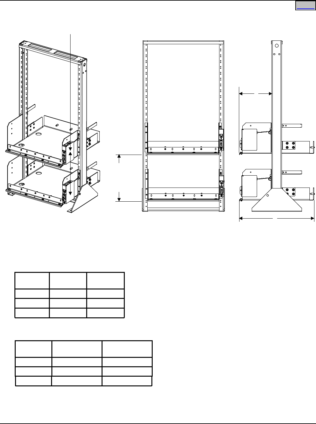
System Application Guide SAG582136600
Spec. No. 582136600 (Model 211NGFB) Issue AU, February 21, 2014
Page 103 of 105
This document is property of Emerson Network Power, Energy Systems, North America, Inc. and contains confidential and proprietary information owned by Emerson Network Power, Energy
Systems, North America, Inc. Any copying, use, or disclosure of it without the written permission of Emerson Network Power, Energy Systems, North America, Inc. is strictly prohibited.
Home
Overall Dimensions – 23” Battery Tray
Optional Battery Disconnect Circuit Breakers
(Shown on Right Side, Available on Either Side)
ISO View
Notes:
1. All dimensions are in inches,
unless otherwise specified.
2. P/N 528496 tray shown.
P/N 540842 and 557573 similar.
3.
4. Weight in LBS.
(per tray, less batteries).
5. Finish: Gray
6. Maximum trays available per rack is three (3).
Tray P/N Dimension
A
Dimension
B
Part No. With Circuit
Breaker Option
Without Circuit
Breaker Option
528496 9.781 24.437
540842 6.90 12.50
557573 10.48 23.14
557573 25 lbs 23 lbs
528496 33 lbs 29 lbs
540842 20 lbs 18 lbs
10.50
12.25
14.00
(as ordered)
Front View
A
See
Note 3
See Note 3
B
Right Side View

SAG582136600 System Application Guide
Issue AU, February 21, 2014 Spec. No. 582136600 (Model 211NGFB)
Page 104 of 105
This document is property of Emerson Network Power, Energy Systems, North America, Inc. and contains confidential and proprietary information owned by Emerson Network Power, Energy
Systems, North America, Inc. Any copying, use, or disclosure of it without the written permission of Emerson Network Power, Energy Systems, North America, Inc. is strictly prohibited.
Home
BATTERY MANUFACTURER INFORMATION
Some equipment described in this System Application Guide is designed to accommodate batteries from
various manufacturers. The following are referenced in this document.
C&D: C&D Technologies, Inc., Powercom Div., 1400 Union Meeting Road, Blue Bell, PA 19422-0858
Deka®: East Penn Mfg. Co., Inc., Lyon Station, PA 19536-0147
Douglas®: Douglas Battery Mfg. Co., 500 Battery Dr., Winston-Salem, NC 27117-2159
MarathonTM: GNB Industrial Power, a Division of Exide Technologies, Princeton, NJ 08543.
Northstar: NorthStar Battery Co. LLC, 4000 Continental Way, Springfield, MO 65803
PowerSafe EnersysTM: EnerSys Inc., Reading, PA, 196212-4145
RELATED DOCUMENTATION
Installation Instructions: Section 6031
User Instructions: Section 6032
Battery Cabinet Spec. No. 541434
Installation and User Instructions: Section 6023
Battery Cabinet Spec. No. 545534
Installation and User Instructions: Section 6033
Battery Cabinet Spec. No. 545506
Installation and User Instructions: Section 6036
Battery Cabinet Spec. No. 554631
Installation and User Instructions: UM554631
Rectifier User Instructions: UM1R481000
SCU+ Controller User Instructions: UM1M521BNA
ACU+ Controller User Instructions: UM1M820BNA
System Application Guide SAG582136600
Spec. No. 582136600 (Model 211NGFB) Issue AU, February 21, 2014
Page 105 of 105
This document is property of Emerson Network Power, Energy Systems, North America, Inc. and contains confidential and proprietary information owned by Emerson Network Power, Energy
Systems, North America, Inc. Any copying, use, or disclosure of it without the written permission of Emerson Network Power, Energy Systems, North America, Inc. is strictly prohibited.
Home
REVISION RECORD
Issue
Change
Number
(ECO)
Description of Change Date Approved
AN LLP217521
Additional Battery P/N added to Battery Table.
Added optional 19” and 23” rear cover kits P/N
555260 and P/N 555261. Added optional digital
input cable kit P/N 554935. Added references to List
73 optional external battery cable assembly P/N
555050. Added PCU blank filler as accessory.
02/20/2013 Shanon
Ravacio
AP
LLP218760
Added Battery Cabinet P/N 554631.
05/16/2013
John Jasko
AR LLP218923
Frame grounding lug adapter P/N 556872 (for use
when wall mounted) added.
09/04/2013 John Jasko
AS LLP218844 Added optional 3” projection mount kit P/N 556828. 09/19/2013
Khristebelle
Ilagan
AT
LLP219497
Option to not power controller during LVBD added.
11/22/2013
John Jasko
AU LLP219376
Added 90A Bullet Breaker P/Ns 138887 and
138888. Added battery tray P/N 557573. Replaced
battery tray P/N 541036 with 558047.
02/21/2014 John Jasko
Emerson Network Power, Energy Systems, North America, Inc.
4350 Weaver Parkway, Warrenville, IL 60555
Toll Free:
800-800-1280 (USA and Canada)
Telephone:
440-246-6999 Fax: 440-246-4876
Web:
EmersonNetworkPower.com/EnergySystems
EnergyNet:
Secure.EmersonNetworkPower.com
John Jasko
Feb 28, 2014 Jerry Li
Mar 4, 2014
