Emerson Netsure 801Db Application Guide
2015-03-30
: Emerson Emerson-Netsure-801Db-Application-Guide-679908 emerson-netsure-801db-application-guide-679908 emerson pdf
Open the PDF directly: View PDF ![]() .
.
Page Count: 72
- SYSTEM OVERVIEW
- TABLE OF CONTENTS
- LIST DESCRIPTIONS
- For Bays being Currently Manufactured (Model 801DB nvgb)
- List 105: Common Equipment, 8-Panel Bay, w/ Basic Metering
- List 106: Common Equipment, 6-Panel Bay, w/ Advanced Metering
- List 107: Common Equipment, 6-Panel Bay, w/ Basic Metering
- List 108: Common Equipment, 8-Panel Bay, w/ Advanced Metering
- List 110: Distribution Panel, 8-Panel Bay
- List 115: Distribution Panel, 8-Panel Bay
- List 116: Optional Internal Ground/Return Bar, 8-Panel Bay (Full Bay Length)
- List 117: Optional Internal Ground/Return Bar, 8-Panel Bay (Panel Length)
- List 118: Blank Distribution Panel Cover, 8-Panel Bay
- List 120: Distribution Panel, 6-Panel Bay
- List 125: Distribution Panel, 6-Panel Bay
- List 126: Optional Internal Ground/Return Bar, 6-Panel Bay (Full Bay Length)
- List 127: Optional Internal Ground/Return Bar, 6-Panel Bay (Panel Length)
- List 128: Blank Distributional Panel Cover, 6-Panel Bay
- List 130: Distribution Panel Paralleling Bar
- List 139: Optional Internal Ground/Return Bar Paralleling Kit, 8-Panel Bay (Panel Length)
- List 143: Bay Input Feed and Shunt Assembly (4 Cables, 25 mV. Shunts)
- List 144: Bay Input Feed and Shunt Assembly (2 Cables, 25 mV. Shunts)
- List 145: Bay Input Feed and Shunt Assembly (2 Cables, 50 mV. Shunts)
- List 147: Bay Input Feed and Shunt Assembly (4 Cables, 50 mV. Shunts)
- List 148: 2400A Ground/Return Input Assembly, with Optional Bonding Strap
- List 150: Optional Capacitor Precharge Assembly
- List 151: Dressing Bar
- List 153: Load Distribution Cable Management Kit
- List 156: Meter and Alarm Card Internal Power In-Line Fuse Kit
- List 166: Meter Panel Field Upgrade Retrofit Kit
- List 167: Pre-Installed Load Lug-Mounting Hardware
- List 168: Meter Panel Field Upgrade Retrofit Kit
- List 170: Assembly, Ethernet
- For Manufactured Discontinued Bays (Model 1293V3)
- For Bays being Currently Manufactured (Model 801DB nvgb)
- ACCESSORY DESCRIPTIONS
- Load Lug Hardware Kits
- Side by Side Busbar Link Kit for Use with List 110 and List 120, P/N 556103
- Side by Side Busbar Link Kit for Use with List 115 and List 125, P/N 557256
- Right Angle Lug Adaptor Kits, P/Ns 556377 and 556378
- External Return/Ground Bar Assemblies
- Seismic Anchor Kit, P/N 545387
- Transient Voltage Surge Suppressor (TVSS) Device
- Distribution Devices and Lug Selection
- Box Framework Extensions
- Wiring Notes
- Wiring Illustrations
- Replacement Alarm, Reference, and Control Fuses, List 105 and 107 Bays
- Replacement Alarm, Reference, and Control Fuses, List 106 and 108 Bays
- Replacement Circuit Cards, List 105 and 107 Bays
- Replacement Circuit Cards, List 106 and 108 Bays
- SPECIFICATIONS
- PHYSICAL SIZE INFORMATION
- RELATED DOCUMENTATION

SAG582120600
System Application Guide
Spec. No. 582120600 (Model 801DB NVGB)
Issue BF, February 21, 2014
Page 1 of 72
This document is property of Emerson Network Power, Energy Systems, North America, Inc. and contains confidential and proprietary information owned by Emerson Network Power, Energy
Systems, North America, Inc. Any copying, use, or disclosure of it without the written permission of Emerson Network Power, Energy Systems, North America, Inc. is strictly prohibited.
SYSTEM OVERVIEW
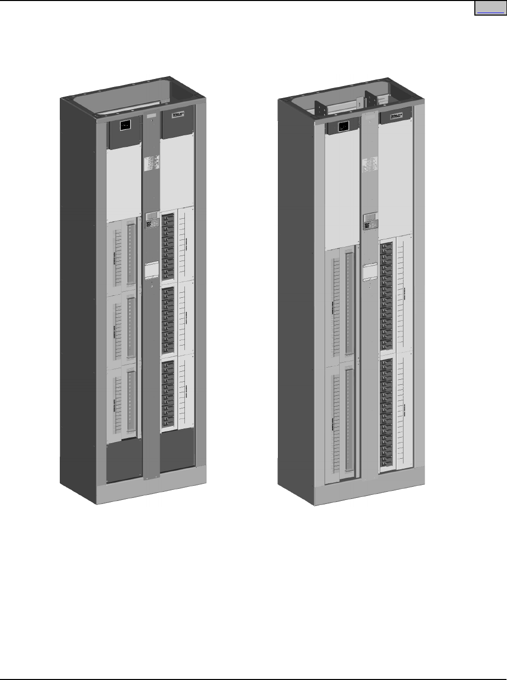
Description: The NetSure™ 801DB NVGB DC Power Distribution is a -48V Battery Distribution Fuse /
Circuit Breaker Bay (BDF/CBB).
• The NetSure™ 801DB NVGB can be ordered as an 8-distribution panel or 6-distribution
panel bay (4 or 3 panels per side).
• Each distribution panel can be configured for separate inputs giving you an 8-load or
6-load bay (must use an external ground/return bar), or the panels per side can be
paralleled to allow one feed per side giving you a 2-load bay (may use the optional
internal ground/return bar). Other configurations include an 8-panel bay with 4-loads and
two loads, and a 6-panel bay with 4-loads (paralleling the top two panels or paralleling
the bottom two panels per side).
• Each bay can be equipped with an optional “full bay length” internal ground/return bar
(per side) (configuration restrictions apply). Another option includes replacing one
(8- and 6-panel bays) or two (8-panel bay only) distribution panels per side with a “panel
length” internal ground/return bar.
• Each bay can easily be configurable for top or bottom feed.
• Each bay is equipped with a digital meter assembly. The List 105 and 107 bays provide
a basic digital meter, which is capable of displaying system load voltage and current on
each Distribution Panel. An advanced Digital Meter/Alarm Panel is provided in the List
106 and 108 bays. In addition to the basic metering functions, this panel provides Low
Voltage, Power Lost, Over-current and Fuse/Circuit Breaker alarms for each panel in the
bay. Also provided are four (4) external alarm relay circuits, to which any combination of
alarms can be mapped. This Meter Panel comes with a comprehensive Web page
capability for remote system management.
Family: NetSure™
Spec. No.: 582120600
Model: 801DB NVGB
Output Voltage: -48 Volts DC
Output Capacity: 640A continuous per Distribution Panel
8-Panel Bay; 2400A Maximum per Side, 4800A Maximum per Bay
6-Panel Bay; 1800A Maximum per Side, 3600A Maximum per Bay
Agency Approval: UL Listed ("cULus"), NEBS
Framework Type: Seismic Rated (Zone 4) Box Framework
Mounting Width: 26”
Mounting Depth: 15”
Mounting Height: 84”
Access: Front and Rear for Installation, Front for Operation and Maintenance
Color: Textured Gray (M500-147)
Environment: 0°C to +40°C (+32°F to +104°F)
Home
SAG582120600 System Application Guide
Issue BF, February 21, 2014 Spec. No. 582120600 (Model 801DB NVGB)
Page 2 of 72
This document is property of Emerson Network Power, Energy Systems, North America, Inc. and contains confidential and proprietary information owned by Emerson Network Power, Energy
Systems, North America, Inc. Any copying, use, or disclosure of it without the written permission of Emerson Network Power, Energy Systems, North America, Inc. is strictly prohibited.
8-Panel Bay 6-Panel Bay
Home
System Application Guide SAG582120600
Spec. No. 582120600 (Model 801DB NVGB) Issue BF, February 21, 2014
Page 3 of 72
This document is property of Emerson Network Power, Energy Systems, North America, Inc. and contains confidential and proprietary information owned by Emerson Network Power, Energy
Systems, North America, Inc. Any copying, use, or disclosure of it without the written permission of Emerson Network Power, Energy Systems, North America, Inc. is strictly prohibited.
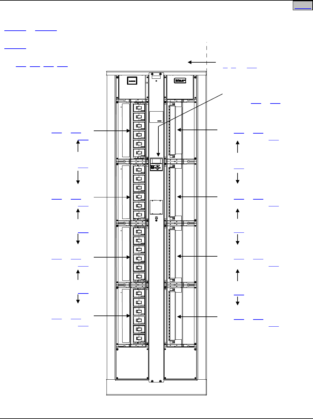
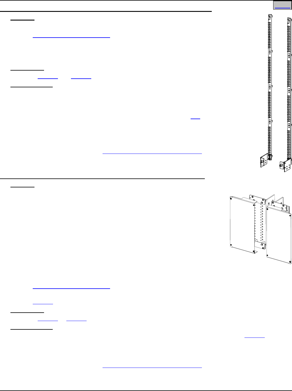
Eight Panel Bay
Front View
Eight Panel Bay
Digital Meter Assembly
P/O List 105 or 108 (shown)
Distribution Panel (B)
(List 110 or 115) or
Blank Panel (List 118)
Box Framework Extension
(1’, 2’, or 4.5’)
Distribution Panel (G)
(List 110 or 115) or
Blank Panel (List 118)
Distribution Panel (H)
(List 110 or 115) or
Blank Panel (List 118)
Distribution Panel (A)
(List 110 or 115) or
Blank Panel (List 118)
Paralleling Bar
(List 130)
Paralleling Bar
(List 130)
Paralleling Bar
(List 130)
Paralleling Bar
(List 130)
Distribution Panel (C)
(List 110 or 115) or
Blank Panel (List 118)
Distribution Panel (D)
(List 110 or 115) or
Blank Panel (List 118)
Distribution Panel (E)
(List 110 or 115) or
Blank Panel (List 118)
Distribution Panel (F)
(List 110 or 115) or
Blank Panel (List 118)
Paralleling Bar
(List 130)
Paralleling Bar
(List 130)
List 105 or List 108 (Common
Equipment)
List 116 (Optional Internal ‘Full
Bay Length’ Ground/Return Bar)
List 143, 144, 145, 147 (Bay
Input Feed and Shunt Assembly)
Home

SAG582120600 System Application Guide
Issue BF, February 21, 2014 Spec. No. 582120600 (Model 801DB NVGB)
Page 4 of 72
This document is property of Emerson Network Power, Energy Systems, North America, Inc. and contains confidential and proprietary information owned by Emerson Network Power, Energy
Systems, North America, Inc. Any copying, use, or disclosure of it without the written permission of Emerson Network Power, Energy Systems, North America, Inc. is strictly prohibited.
Eight Panel Bay (cont’d)
OTHER OPTIONS
List 117 (Optional Internal
‘Panel Length’ Ground/Return Bar)
List 139 (Optional Internal ‘Panel Length’
Ground/Return Bar Paralleling Kit)
List 148 (2400A Ground/Return Input
Assembly, with Optional Bonding Strap for
List 116 Ground/Return Bar)
List 150 (Optional Capacitor
Precharge Assembly)
List 151 (Dressing Bar)
List 153 (Load Distribution
Cable Management Kit)
List 156 (Meter and Alarm Card
Internal Power In-Line Fuse Kit, for List 105
bay)
List 167 (Pre-Installed Load Lug Hardware)
List 168 (Field Installable Advanced Meter
Panel for older 8-Panel BDFBs)
See Also
System Overview
Table of Contents
List Descriptions
Accessory Descriptions
Specifications
Physical Size Information
Related Documentation
Home
System Application Guide SAG582120600
Spec. No. 582120600 (Model 801DB NVGB) Issue BF, February 21, 2014
Page 5 of 72
This document is property of Emerson Network Power, Energy Systems, North America, Inc. and contains confidential and proprietary information owned by Emerson Network Power, Energy
Systems, North America, Inc. Any copying, use, or disclosure of it without the written permission of Emerson Network Power, Energy Systems, North America, Inc. is strictly prohibited.
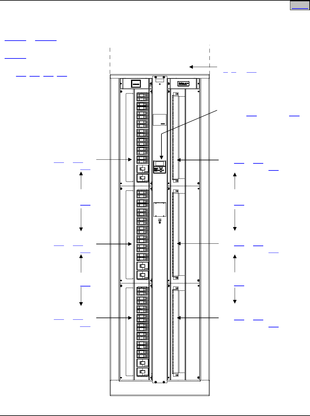
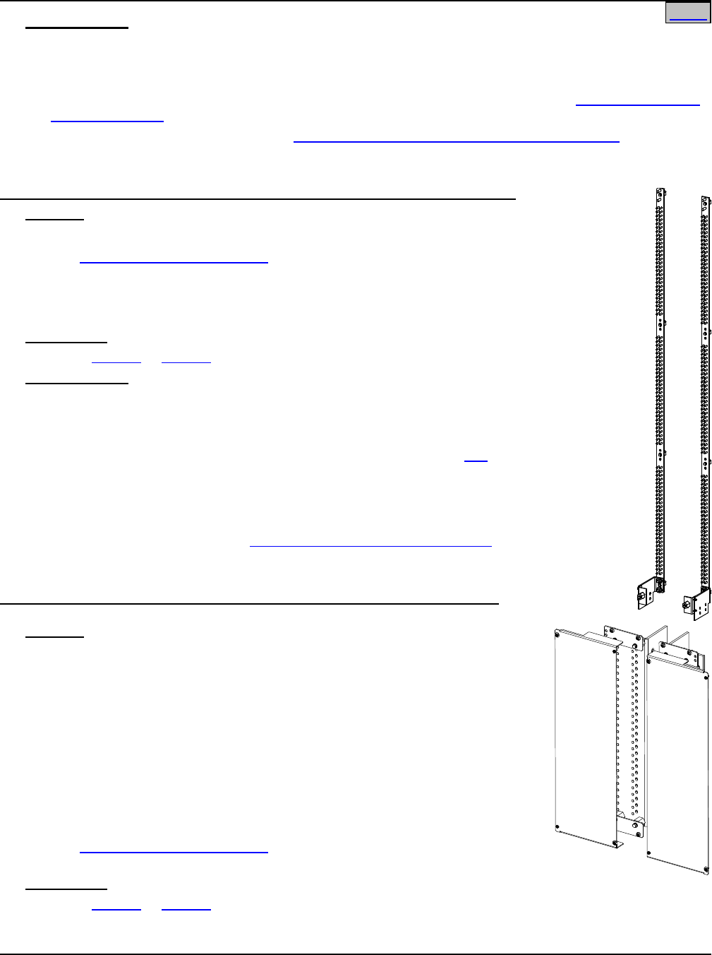
Six Panel Bay
Front View
Six Panel Bay
Digital Meter Assembly
P/O List 106 (shown) or 107
Distribution Panel (B)
(List 120 or 125) or
Blank Panel (List 128)
Box Framework Extension
(1’, 2’, or 4.5’)
Distribution Panel (D)
(List 120 or 125) or
Blank Panel (List 128)
Distribution Panel (E)
(List 120 or 125) or
Blank Panel (List 128)
Distribution Panel (F)
(List 120 or 125) or
Blank Panel (List 128)
Distribution Panel (C)
(List 120 or 125) or
Blank Panel (List 128)
Distribution Panel (A)
(List 120 or 125) or
Blank Panel (List 128)
Paralleling Bar
(List 130)
Paralleling Bar
(List 130)
Paralleling Bar
(List 130)
Paralleling Bar
(List 130)
List 106 or List 107 (Common
Equipment)
List 126 (Optional Internal ‘Full
Bay Length’ Ground/Return Bar)
List 143, 144, 145, 147 (Bay
Input Feed and Shunt Assembly)
Home

SAG582120600 System Application Guide
Issue BF, February 21, 2014 Spec. No. 582120600 (Model 801DB NVGB)
Page 6 of 72
This document is property of Emerson Network Power, Energy Systems, North America, Inc. and contains confidential and proprietary information owned by Emerson Network Power, Energy
Systems, North America, Inc. Any copying, use, or disclosure of it without the written permission of Emerson Network Power, Energy Systems, North America, Inc. is strictly prohibited.
Six Panel Bay (cont’d)
OTHER OPTIONS
List 127 (Optional Internal
‘Panel Length’ Ground/Return Bar)
List 148 (2400A Ground/Return Input
Assembly, with Optional Bonding Strap for
List 126 Ground/Return Bar)
List 150 (Optional Capacitor
Precharge Assembly)
List 151 (Dressing Bar)
List 153 (Load Distribution
Cable Management Kit)
List 156 (Meter and Alarm Card
Internal Power In-Line Fuse Kit, for List 107
bay)
List 167 (Pre-Installed Load Lug Hardware)
List 166 (Field Installable Advanced Meter
Panel for older 6-Panel BDFBs)
See Also
System Overview
Table of Contents
List Descriptions
Accessory Descriptions
Specifications
Physical Size Information
Related Documentation
Home

System Application Guide SAG582120600
Spec. No. 582120600 (Model 801DB NVGB) Issue BF, February 21, 2014
Page 7 of 72
This document is property of Emerson Network Power, Energy Systems, North America, Inc. and contains confidential and proprietary information owned by Emerson Network Power, Energy
Systems, North America, Inc. Any copying, use, or disclosure of it without the written permission of Emerson Network Power, Energy Systems, North America, Inc. is strictly prohibited.
TABLE OF CONTENTS
System
Overview Picture List
Descriptions
Accessory
Descriptions Specifications Physical Size
Information
Related
Documentation
SYSTEM OVERVIEW................................................................................................................................................. 1
Eight Panel Bay ................................................................................................................................................... 3
Six Panel Bay ....................................................................................................................................................... 5
TABLE OF CONTENTS ............................................................................................................................................. 7
LIST DESCRIPTIONS ................................................................................................................................................ 9
For Bays being Currently Manufactured (Model 801DB NVGB) ....................................................................... 9
List 105: Common Equipment, 8-Panel Bay, w/ Basic Metering .................................................................... 9
List 106: Common Equipment, 6-Panel Bay, w/ Advanced Metering ........................................................... 10
List 107: Common Equipment, 6-Panel Bay, w/ Basic Metering .................................................................. 11
List 108: Common Equipment, 8-Panel Bay, w/ Advanced Metering ........................................................... 12
List 110: Distribution Panel, 8-Panel Bay ...................................................................................................... 13
List 115: Distribution Panel, 8-Panel Bay ...................................................................................................... 13
List 116: Optional Internal Ground/Return Bar, 8-Panel Bay (Full Bay Length) ........................................... 14
List 117: Optional Internal Ground/Return Bar, 8-Panel Bay (Panel Length) ............................................... 14
List 118: Blank Distribution Panel Cover, 8-Panel Bay ................................................................................. 15
List 120: Distribution Panel, 6-Panel Bay ...................................................................................................... 15
List 125: Distribution Panel, 6-Panel Bay ...................................................................................................... 15
List 126: Optional Internal Ground/Return Bar, 6-Panel Bay (Full Bay Length) ........................................... 16
List 127: Optional Internal Ground/Return Bar, 6-Panel Bay (Panel Length) ............................................... 16
List 128: Blank Distributional Panel Cover, 6-Panel Bay .............................................................................. 17
List 130: Distribution Panel Paralleling Bar ................................................................................................... 17
List 139: Optional Internal Ground/Return Bar Paralleling Kit, 8-Panel Bay (Panel Length) ........................ 17
List 143: Bay Input Feed and Shunt Assembly (4 Cables, 25 mV. Shunts) ................................................. 18
List 144: Bay Input Feed and Shunt Assembly (2 Cables, 25 mV. Shunts) ................................................. 18
List 145: Bay Input Feed and Shunt Assembly (2 Cables, 50 mV. Shunts) ................................................. 19
List 147: Bay Input Feed and Shunt Assembly (4 Cables, 50 mV. Shunts) ................................................. 19
List 148: 2400A Ground/Return Input Assembly, with Optional Bonding Strap ............................................ 20
List 150: Optional Capacitor Precharge Assembly ....................................................................................... 20
List 151: Dressing Bar ................................................................................................................................... 21
List 153: Load Distribution Cable Management Kit ....................................................................................... 21
List 156: Meter and Alarm Card Internal Power In-Line Fuse Kit ................................................................. 21
List 166: Meter Panel Field Upgrade Retrofit Kit ........................................................................................... 22
List 167: Pre-Installed Load Lug-Mounting Hardware................................................................................... 22
List 168: Meter Panel Field Upgrade Retrofit Kit ........................................................................................... 23
List 170: Assembly, Ethernet ........................................................................................................................ 23
For Manufactured Discontinued Bays (Model 1293V3) ................................................................................. 24
ACCESSORY DESCRIPTIONS ............................................................................................................................... 26
Load Lug Hardware Kits ................................................................................................................................... 26
Side by Side Busbar Link Kit for Use with List 110 and List 120, P/N 556103 ............................................ 26
Side by Side Busbar Link Kit for Use with List 115 and List 125, P/N 557256 ............................................ 26
Right Angle Lug Adaptor Kits, P/Ns 556377 and 556378 .............................................................................. 28
External Return/Ground Bar Assemblies ....................................................................................................... 29
Seismic Anchor Kit, P/N 545387 ...................................................................................................................... 30
Transient Voltage Surge Suppressor (TVSS) Device .................................................................................... 30
Distribution Devices and Lug Selection.......................................................................................................... 31
TLS/TPS Fuses/Fuseblocks, TPL Fuses/Fuseblocks, and Lug Selection for Lists 110 and 120 .................. 31

SAG582120600 System Application Guide
Issue BF, February 21, 2014 Spec. No. 582120600 (Model 801DB NVGB)
Page 8 of 72
This document is property of Emerson Network Power, Energy Systems, North America, Inc. and contains confidential and proprietary information owned by Emerson Network Power, Energy
Systems, North America, Inc. Any copying, use, or disclosure of it without the written permission of Emerson Network Power, Energy Systems, North America, Inc. is strictly prohibited.
Bullet Nose-Type Circuit Breakers, Bullet Nose-Type Fuseblocks e/w TLS/TPS Fuses, and Lug
Selection for Lists 115 and 125 ...................................................................................................................... 35
Box Framework Extensions ............................................................................................................................. 41
One (1) Foot Box Framework Extension ........................................................................................................ 41
Two (2) Foot Box Framework Extension ........................................................................................................ 41
Four and One-Half (4-1/2) Foot Box Framework Extension .......................................................................... 41
Wiring Notes ...................................................................................................................................................... 42
Bay Frame Grounding Wire Sizes and Lugs Selection .................................................................................. 42
External Alarm Wiring—List 105 and 107 Bays ............................................................................................. 42
External Alarm and Control Wiring—List 106 and 108 Bays ......................................................................... 42
Load Distribution Wire Sizes Selection .......................................................................................................... 43
DC Input Cable Sizes and Lugs Selection ..................................................................................................... 47
Wiring Illustrations ............................................................................................................................................ 48
Overall Installer’s Connections ....................................................................................................................... 48
Bay Frame Grounding Connection................................................................................................................. 49
External Alarm and Meter/Alarm Card Input Connections ............................................................................. 50
Load Distribution Connections—Lists 105, 106, 107, 108 ............................................................................. 55
DC Input Connections .................................................................................................................................... 61
Replacement Alarm, Reference, and Control Fuses, List 105 and 107 Bays .............................................. 64
Fuseblock Located in Bay’s Top Center ........................................................................................................ 64
Replacement Alarm, Reference, and Control Fuses, List 106 and 108 Bays .............................................. 64
Fuses Located on Auxiliary Fuse Card at Top of Bay.................................................................................... 64
Replacement Circuit Cards, List 105 and 107 Bays ....................................................................................... 65
Replacement Circuit Cards, List 106 and 108 Bays ....................................................................................... 65
SPECIFICATIONS .................................................................................................................................................... 66
1.1 DC Operating Voltage ............................................................................................................................... 66
1.2 Environmental Ratings ............................................................................................................................. 66
1.3 Compliance Information ........................................................................................................................... 66
1.4 Output Ratings ........................................................................................................................................... 66
1.5 Standard Features—Lists 105 and 107 ................................................................................................... 66
1.6 Standard Features—Lists 106 and 108 ................................................................................................... 67
PHYSICAL SIZE INFORMATION ............................................................................................................................ 68
Floor Hole Drilling Pattern Dimensions .......................................................................................................... 68
Dimensions, 8-Bus Bay .................................................................................................................................... 69
Dimensions, 6-Bus Bay .................................................................................................................................... 70
RELATED DOCUMENTATION ................................................................................................................................ 71
REVISION RECORD ................................................................................................................................................ 72

System Application Guide SAG582120600
Spec. No. 582120600 (Model 801DB NVGB) Issue BF, February 21, 2014
Page 9 of 72
This document is property of Emerson Network Power, Energy Systems, North America, Inc. and contains confidential and proprietary information owned by Emerson Network Power, Energy
Systems, North America, Inc. Any copying, use, or disclosure of it without the written permission of Emerson Network Power, Energy Systems, North America, Inc. is strictly prohibited.
LIST DESCRIPTIONS
For Bays being Currently Manufactured (Model 801DB NVGB)
List 105: Common Equipment, 8-Panel Bay, w/ Basic Metering
Features
♦ List 105 provides the common equipment for an 8-Distribution Panel BDF/CBB (Battery Distribution
Fuse/Circuit Breaker Bay) with basic metering.
♦ Configurable for top or bottom feed.
♦ Consists of a 7’H x 26”W x 15”D welded box framework (seismic, zone 4 earthquake compliant).
♦ Includes a basic digital meter panel for indicating voltage and current for each panel in the bay.
Restrictions
None.
Ordering Notes
1) Order up to eight (8) Lists 110 and/or List 115 Distribution Panels per bay.
2) If List 110 is ordered, order a List 150 Capacitor Precharge Assembly, if required.
3) For any open Distribution Panel position, order a List 118 Blank Panel.
4) Order List 145 or 147 Input Feed and Shunt Assembly as required. Each List 145 or 147 provides input
terminations and shunts for both sides.
For top and bottom feed 2-load applications, order one (1) List 145 or 147 and specify top or bottom feed.
For top and bottom feed multi-load applications, order one (1) List 145 or 147 for each Side A/Side B load
and specify top or bottom feed.
5) If Distribution Panels (per side) are to be paralleled, order a List 130 Distribution Panel Paralleling Bar.
Each List 130 includes two (2) Paralleling Bars (one per side).
6) Order List 116 or List 117 Internal Ground Bars as required, or External Ground Bars (see ACCESSORY
DESCRIPTIONS section) as required.
7) List 116 provides input lug landing points at the top or bottom (as specified) of the full bay length
ground/return busbars. List 116 internal return bars are rated for 1200 Amps. List 148 is available to
increase that capacity to 2400 Amps and add additional cable landing points. Each bay can
accommodate (1) List 148. List 148 offers cable termination at the rear of the bay and the option of a
bonding strap.
8) Order List 151 Cable Dressing Bars as required.
9) Order List 156 Meter and Alarm Card Input Power In-Line Fuse Kit as required.
10) Order a 1’, 2’, or 4-1/2’ Box Framework Extension as required.
11) Order distribution fuses, circuit breakers, and load lugs as required per Distribution Devices and Lug
Selection in ACCESSORY DESCRIPTIONS.
12) For Load and Load Return lug-mounting hardware, order Load Lug Hardware Kits (ship-loose) as
required, or order List 167 (pre-installed).
13) Order TVSS Device(s) as required per Transient Voltage Surge Suppressor (TVSS) Device in
ACCESSORY DESCRIPTIONS.
14) Order DC input lugs as required per DC Input Cable Sizes and Lugs Selection under Wiring Notes in
ACCESSORY DESCRIPTIONS.
15) Order bay frame grounding lugs as required per Bay Frame Grounding Wire Sizes and Lugs Selection
under Wiring Notes in ACCESSORY DESCRIPTIONS.
Home

SAG582120600 System Application Guide
Issue BF, February 21, 2014 Spec. No. 582120600 (Model 801DB NVGB)
Page 10 of 72
This document is property of Emerson Network Power, Energy Systems, North America, Inc. and contains confidential and proprietary information owned by Emerson Network Power, Energy
Systems, North America, Inc. Any copying, use, or disclosure of it without the written permission of Emerson Network Power, Energy Systems, North America, Inc. is strictly prohibited.
List 106: Common Equipment, 6-Panel Bay, w/ Advanced Metering
Features
♦ List 106 provides the common equipment for a 6-Distribution Panel BDF/CBB (Battery Distribution
Fuse/Circuit Breaker Bay) with advanced metering.
♦ Configurable for top or bottom feed.
♦ Consists of a 7’H x 26”W x 15”D welded box framework (seismic, zone 4 earthquake compliant).
♦ Includes an Advanced Meter/Alarm Panel that provides the following functions for each panel in the bay:
voltage and current metering and Low Voltage, Power Lost, Overcurrent, and Fuse/Circuit Breaker
alarms. Also provided are four (4) external alarm relay circuits, to which any combination of alarms can
be mapped.
♦ Provides four (4) fused auxiliary -48V power outputs (1-1/3A), fused remote (A/B) meter panel inputs,
internal/external sense option, and an Ethernet connection (requires List 170 Ethernet option).
Restrictions
None.
Ordering Notes
1) Order up to six (6) Lists 120 and/or List 125 Distribution Panels per bay.
2) If List 120 is ordered, order a List 150 Capacitor Precharge Assembly, if required.
3) For any open Distribution Panel position, order a List 128 Blank Panel.
4) Order List 143 or 144 Input Feed and Shunt Assembly as required. Each List 143 or 144 provides input
terminations and shunts for both sides.
For top and bottom feed 2-load applications, order one (1) List 143 or 144 and specify top or bottom feed.
For top and bottom feed multi-load applications, order three (3) List 143 or 144 for each Side A/Side B
load and specify top or bottom feed.
List 120 Only: For 3-load side by side applications, order three (3) List 143 or 144, and order three (3)
556103.
List 125 Only: For 3-load side by side applications, order three (3) List 143 or 144, and order three (3)
557256.
5) If Distribution Panels (per side) are to be paralleled, order a List 130 Distribution Panel Paralleling Bar.
Each List 130 includes two (2) Paralleling Bars (one per side).
6) Order List 126 or List 127 Internal Ground Bars as required, or External Ground Bars (see ACCESSORY
DESCRIPTIONS section) as required.
7) List 126 provides input lug landing points at the top or bottom (as specified) of the full bay length
ground/return busbars. List 126 internal return bars are rated for 1200 Amps. List 148 is available to
increase that capacity to 2400 Amps and provide additional cable landing points. Each bay can
accommodate (1) List 148. List 148 offers cable termination at the rear of the bay and the option of a
bonding strap.
8) Order List 151 Cable Dressing Bars as required.
9) Order List 156 Meter and Alarm Card Input Power In-Line Fuse Kit as required.
10) Order a 1’, 2’, or 4-1/2’ Box Framework Extension as required.
11) Order distribution fuses, circuit breakers, and load lugs as required per Distribution Devices and Lug
Selection in ACCESSORY DESCRIPTIONS.
12) For Load and Load Return lug-mounting hardware, order Load Lug Hardware Kits (ship-loose) as
required, or order List 167 (pre-installed).
13) Order TVSS Device(s) as required per Transient Voltage Surge Suppressor (TVSS) Device in
ACCESSORY DESCRIPTIONS.
14) Order DC input lugs as required per DC Input Cable Sizes and Lugs Selection under Wiring Notes in
ACCESSORY DESCRIPTIONS.
Home

System Application Guide SAG582120600
Spec. No. 582120600 (Model 801DB NVGB) Issue BF, February 21, 2014
Page 11 of 72
This document is property of Emerson Network Power, Energy Systems, North America, Inc. and contains confidential and proprietary information owned by Emerson Network Power, Energy
Systems, North America, Inc. Any copying, use, or disclosure of it without the written permission of Emerson Network Power, Energy Systems, North America, Inc. is strictly prohibited.
15) Order bay frame grounding lugs as required per Bay Frame Grounding Wire Sizes and Lugs
Selection under Wiring Notes in ACCESSORY DESCRIPTIONS.
16) For remote access capability, order one (1) List 170 Ethernet option.
List 107: Common Equipment, 6-Panel Bay, w/ Basic Metering
Features
♦ List 107 provides the common equipment for a 6-Distribution Panel BDF/CBB (Battery Distribution
Fuse/Circuit Breaker Bay) with basic metering.
♦ Configurable for top or bottom feed.
♦ Consists of a 7’H x 26”W x 15”D welded box framework (seismic, zone 4 earthquake compliant).
♦ Includes a basic digital meter panel for indicating voltage and current for each panel in the bay.
Restrictions
None.
Ordering Notes
1) Order up to six (6) Lists 120 and/or List 125 Distribution Panels per bay.
2) If List 120 is ordered, order a List 150 Capacitor Precharge Assembly, if required.
3) For any open Distribution Panel position, order a List 128 Blank Panel.
4) Order List 145 or 147 Input Feed and Shunt Assembly as required. Each List 145 or 147 provides input
terminations and shunts for both sides.
For top and bottom feed 2-load applications, order one (1) List 145 or 147 and specify top or bottom feed.
For top and bottom feed multi-load applications, order one (1) List 145 or 147 for each Side A/Side B load
and specify top or bottom feed.
5) If Distribution Panels (per side) are to be paralleled, order a List 130 Distribution Panel Paralleling Bar.
Each List 130 includes two (2) Paralleling Bars (one per side).
6) Order List 126 or List 127 Internal Ground Bars as required, or External Ground Bars (see ACCESSORY
DESCRIPTIONS section) as required.
7) List 126 provides input lug landing points at the top or bottom (as specified) of the full bay length
ground/return busbars. List 126 internal return bars are rated for 1200 Amps. List 148 is available to
increase that capacity to 2400 Amps and provide additional cable landing points. Each bay can
accommodate (1) List 148. List 148 offers cable termination at the rear of the bay and the option of a
bonding strap.
8) Order List 151 Cable Dressing Bars as required.
9) Order List 156 Meter and Alarm Card Input Power In-Line Fuse Kit as required.
10) Order a 1’, 2’, or 4-1/2’ Box Framework Extension as required.
11) Order distribution fuses, circuit breakers, and load lugs as required per Distribution Devices and Lug
Selection in ACCESSORY DESCRIPTIONS.
12) For Load and Load Return lug-mounting hardware, order Load Lug Hardware Kits (ship-loose) as
required, or order List 167 (pre-installed).
13) Order TVSS Device(s) as required per Transient Voltage Surge Suppressor (TVSS) Device in
ACCESSORY DESCRIPTIONS.
14) Order DC input lugs as required per DC Input Cable Sizes and Lugs Selection under Wiring Notes in
ACCESSORY DESCRIPTIONS.
15) Order bay frame grounding lugs as required per Bay Frame Grounding Wire Sizes and Lugs Selection
under Wiring Notes in ACCESSORY DESCRIPTIONS.
Home

SAG582120600 System Application Guide
Issue BF, February 21, 2014 Spec. No. 582120600 (Model 801DB NVGB)
Page 12 of 72
This document is property of Emerson Network Power, Energy Systems, North America, Inc. and contains confidential and proprietary information owned by Emerson Network Power, Energy
Systems, North America, Inc. Any copying, use, or disclosure of it without the written permission of Emerson Network Power, Energy Systems, North America, Inc. is strictly prohibited.
List 108: Common Equipment, 8-Panel Bay, w/ Advanced Metering
Features
♦ List 108 provides the common equipment for an 8-Distribution Panel BDF/CBB (Battery Distribution
Fuse/Circuit Breaker Bay) with advanced metering.
♦ Configurable for top or bottom feed.
♦ Consists of a 7’H x 26”W x 15”D welded box framework (seismic, zone 4 earthquake compliant).
♦ Includes an Advanced Meter/Alarm Panel that provides the following functions for each panel in the bay:
voltage and current metering and Low Voltage, Power Lost, Overcurrent, and Fuse/Circuit Breaker
alarms. Also provided are four (4) external alarm relay circuits, to which any combination of alarms can
be mapped.
♦ Provides four (4) fused auxiliary -48V power outputs (1-1/3A), fused remote (A/B) meter panel inputs,
internal/external sense option, and an Ethernet connection (requires List 170 Ethernet option).
Restrictions
None.
Ordering Notes
1) Order up to eight (8) Lists 110 and/or List 115 Distribution Panels per bay.
2) If List 110 is ordered, order a List 150 Capacitor Precharge Assembly, if required.
3) For any open Distribution Panel position, order a List 118 Blank Panel.
4) Order List 143 or 144 Input Feed and Shunt Assembly as required. See Restrictions above. Each List
143 or 144 provides input terminations and shunts for both sides.
For top and bottom feed 2-load applications, order one (1) List 143 or 144 and specify top or bottom feed.
For top and bottom feed multi-load applications, order two (2) or four (4) List 143 or 144 for each Side
A/Side B load and specify top or bottom feed. Order List 130 as required.
List 110 Only: For 4-load side by side applications, order four (4) List 143 or 144, and order four (4)
556103. For top and bottom feed 2-load side by side applications, order two (2) List 143 or 144, two (2)
556103, and two (2) List 130.
List 115 Only: For 4-load side by side applications, order four (4) List 143 or 144, and order four (4)
557256. For top and bottom feed 2-load side by side applications, order two (2) List 143 or 144, two (2)
557256, and two (2) List 130.
5) If Distribution Panels (per side) are to be paralleled, order a List 130 Distribution Panel Paralleling Bar.
Each List 130 includes two (2) Paralleling Bars (one per side).
6) Order List 116 or List 117 Internal Ground Bars as required, or External Ground Bars (see ACCESSORY
DESCRIPTIONS section) as required.
7) List 116 provides input lug landing points at the top or bottom (as specified) of the full bay length
ground/return busbars. List 116 internal return bars are rated for 1200 Amps. List 148 is available to
increase that capacity to 2400 Amps and provide additional cable landing points. Each bay can
accommodate (1) List 148. List 148 offers cable termination at the rear of the bay and the option of a
bonding strap.
8) Order List 151 Cable Dressing Bars as required.
9) Order List 156 Meter and Alarm Card Input Power In-Line Fuse Kit as required.
10) Order a 1’, 2’, or 4-1/2’ Box Framework Extension as required.
11) Order distribution fuses, circuit breakers, and load lugs as required per Distribution Devices and Lug
Selection in ACCESSORY DESCRIPTIONS.
12) For Load and Load Return lug-mounting hardware, order Load Lug Hardware Kits (ship-loose) as
required, or order List 167 (pre-installed).
13) Order TVSS Device(s) as required per Transient Voltage Surge Suppressor (TVSS) Device in
ACCESSORY DESCRIPTIONS.
14) Order DC input lugs as required per DC Input Cable Sizes and Lugs Selection under Wiring Notes in
ACCESSORY DESCRIPTIONS.
Home
System Application Guide SAG582120600
Spec. No. 582120600 (Model 801DB NVGB) Issue BF, February 21, 2014
Page 13 of 72
This document is property of Emerson Network Power, Energy Systems, North America, Inc. and contains confidential and proprietary information owned by Emerson Network Power, Energy
Systems, North America, Inc. Any copying, use, or disclosure of it without the written permission of Emerson Network Power, Energy Systems, North America, Inc. is strictly prohibited.
15) Order bay frame grounding lugs as required per Bay Frame Grounding Wire Sizes and Lugs
Selection under Wiring Notes in ACCESSORY DESCRIPTIONS.
16) For remote access capability, order one (1) List 170 Ethernet option.
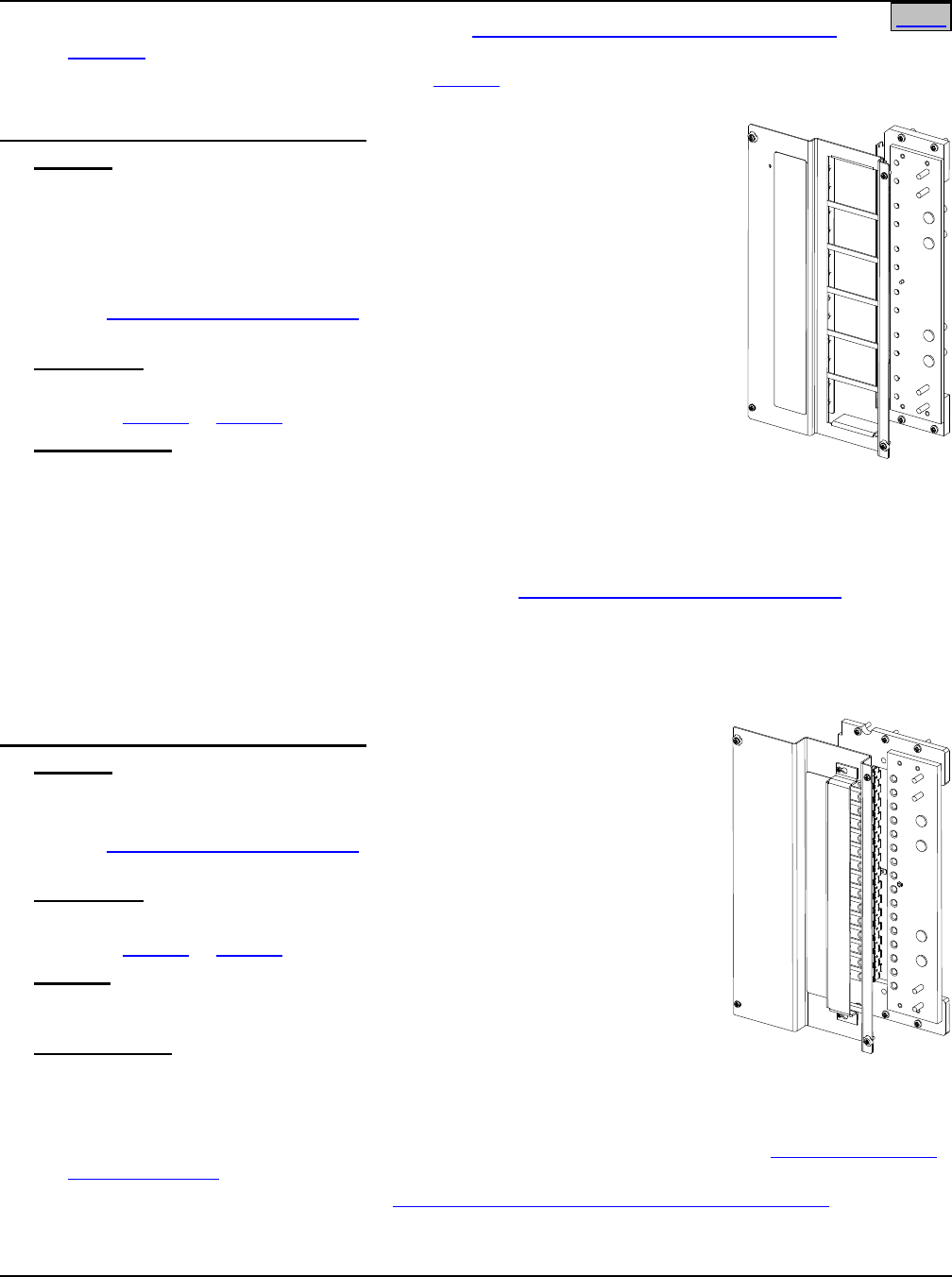
List 110: Distribution Panel, 8-Panel Bay
Features
♦ Twelve (12) TLS/TPS fuse positions, or six (6) TPL fuse positions, or a
combination of TLS/TPS and TPL fuse positions.
♦ Includes (12) TLS/TPS Fuseholders P/N 248817100. For panels factory
configured in a bay, each TPL Fuseholder P/N 516241 ordered replaces (2)
P/N 248817100 Fuseholders.
♦ See Load Distribution Connections under Wiring Illustrations in ACCESSORY
DESCRIPTIONS for load termination specifications.
Restrictions
640A maximum continuous.
For use in List 105 or List 108 only.
Ordering Notes
1) Order as required.
2) Specify up to twelve (12) TLS/TPS fuseholders, or up to six (6) TPL fuseholders, or a combination per
Distribution Panel (all positions MUST be filled). This instructs the factory how to configure the
Distribution Panel. Also specify mounting location for each configured Distribution Panel per bay. This
instructs the factory where to mount each configured Distribution Panel per bay.
3) Order distribution fuses and load lugs as required per Distribution Devices and Lug Selection in
ACCESSORY DESCRIPTIONS.
4) Replacement panels will be equipped with 12 TLS/TPS Fuseholders. TPL fuseholders (P/N 516241) may
be ordered to field modify the distribution panel. One TPL fuseholder takes the space of two TLS/TPS
fuseholders.
List 115: Distribution Panel, 8-Panel Bay
Features
♦ Sixteen (16) bullet nose circuit breaker and/or TLS/TPS Fuse (with bullet
nose fuseholder) positions.
♦ See Load Distribution Connections under Wiring Illustrations in
ACCESSORY DESCRIPTIONS for load termination specifications.
Restrictions
640A maximum continuous.
For use in List 105 or List 108 only.
Caution: Circuit breaker with a 150 ampere or greater rating SHALL HAVE
an empty mounting position between it and any other overcurrent
protective device.
Ordering Notes
1) Order as required.
2) Specify mounting location for each Distribution Panel per bay. This instructs the factory where to mount
each Distribution Panel when the bay is populated with different types of Distribution Panels.
3) Order distribution fuses, fuseholders, circuit breakers, and load lugs as required per Distribution Devices
and Lug Selection in ACCESSORY DESCRIPTIONS.
4) Order TVSS Device(s) as required per Transient Voltage Surge Suppressor (TVSS) Device in
ACCESSORY DESCRIPTIONS.
Home
SAG582120600 System Application Guide
Issue BF, February 21, 2014 Spec. No. 582120600 (Model 801DB NVGB)
Page 14 of 72
This document is property of Emerson Network Power, Energy Systems, North America, Inc. and contains confidential and proprietary information owned by Emerson Network Power, Energy
Systems, North America, Inc. Any copying, use, or disclosure of it without the written permission of Emerson Network Power, Energy Systems, North America, Inc. is strictly prohibited.
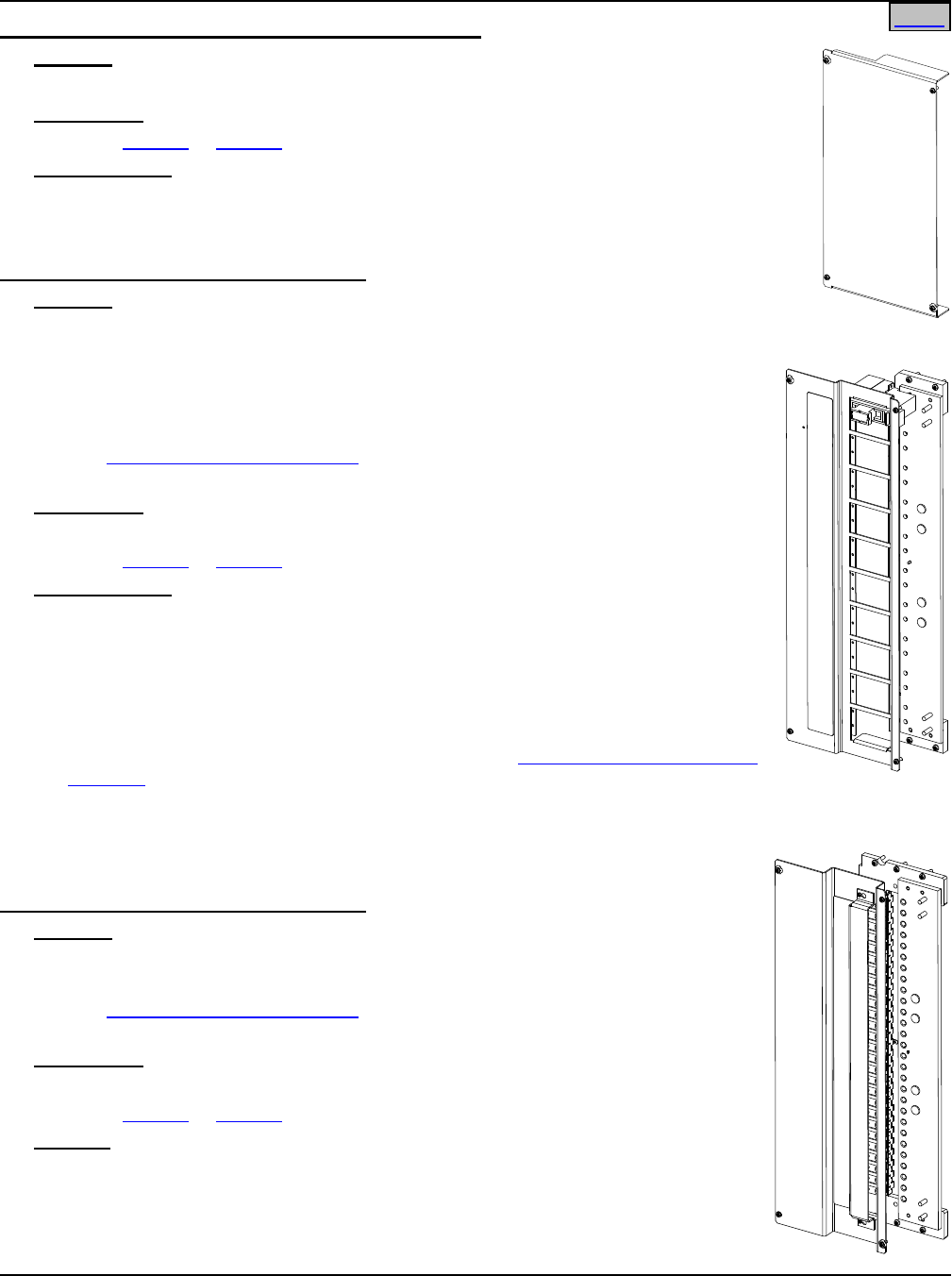
List 116: Optional Internal Ground/Return Bar, 8-Panel Bay (Full Bay Length)
Features
♦ Provides two full bay length internal ground/return bars (one per side).
♦ See Load Distribution Connections under Wiring Illustrations in ACCESSORY
DESCRIPTIONS for load termination specifications.
♦ Includes two (2) Input Lug Landing Plate Assemblies (one per side).
♦ Can be configured for top or bottom feed.
Restrictions
For use in List 105 and List 108 only.
Ordering Notes
1) Order as required.
2) Specify mounting location of included Input Lug Landing Plate Assemblies: top for top-feed
or bottom for bottom feed.
3) List 116 internal ground/return bars are rated for 1200 Amps. List 148 is available to
increase that capacity to 2400 Amps and provide additional cable landing points. Each bay
can accommodate (1) List 148. List 148 offers cable termination at the rear of the bay and
the option of a bonding strap. Mounting location (top or bottom) of List 148 will be opposite
that specified for the Input Lug Landing Plate Assemblies of List 116.
4) Order load lugs as required per Distribution Devices and Lug Selection in ACCESSORY
DESCRIPTIONS.
List 117: Optional Internal Ground/Return Bar, 8-Panel Bay (Panel Length)
Features
♦ Replaces a Distribution Panel on the left and right side with a panel length
internal ground/return bar.
♦ Consists of two (2) ground/return bar assemblies and two (2) blank cover
panels.
♦ For installation in top feed or bottom feed arrangements. When used in top
feed arrangements, ground bar assemblies are installed in top most left and
right Distribution Panel mounting positions (appropriate blank cover panels are
also installed in these positions). When used in bottom feed arrangements,
ground bar assemblies are installed in bottom most left and right Distribution
Panel mounting positions (appropriate blank cover panels are also installed in
these positions). When an additional List 117 is ordered, these additional
ground bar assemblies are installed in the adjacent Distribution Panel mounting
positions (appropriate blank cover panels are supplied and installed in these positions).
♦ See Load Distribution Connections under Wiring Illustrations in ACCESSORY DESCRIPTIONS for load
termination specifications.
♦ See List 139 for a paralleling kit when two (2) List 117 are ordered for the same bay.
Restrictions
For use in List 105 or List 108 only.
Ordering Notes
1) Order as required. Order two (2) List 117 for a fully configured bay. Also order one (1) List 139
Paralleling Kit if two (2) List 117 are ordered.
2) Specify top feed or bottom feed to instruct the factory to mount the Internal Ground/Return Bars at the top
or bottom of the bay.
3) Order load lugs as required per Distribution Devices and Lug Selection in ACCESSORY
DESCRIPTIONS.
Home
System Application Guide SAG582120600
Spec. No. 582120600 (Model 801DB NVGB) Issue BF, February 21, 2014
Page 15 of 72
This document is property of Emerson Network Power, Energy Systems, North America, Inc. and contains confidential and proprietary information owned by Emerson Network Power, Energy
Systems, North America, Inc. Any copying, use, or disclosure of it without the written permission of Emerson Network Power, Energy Systems, North America, Inc. is strictly prohibited.
List 118: Blank Distribution Panel Cover, 8-Panel Bay
Features
♦ Covers an unused Distribution Panel position.
Restrictions
For use in List 105 or List 108 only.
Ordering Notes
1) Order one (1) List 118 for each position in the bay that is NOT populated with a
Distribution Panel.
List 120: Distribution Panel, 6-Panel Bay
Features
♦ Twenty (20) TLS/TPS fuse positions, or ten (10) TPL fuse positions, or a
combination of TLS/TPS and TPL fuse positions.
♦ Includes (20) TLS/TPS Fuseholders P/N 248817100. For panels factory
configured in a bay, each TPL Fuseholder P/N 516241 ordered replaces (2) P/N
248817100 Fuseholders.
♦ See Load Distribution Connections under Wiring Illustrations in ACCESSORY
DESCRIPTIONS for load termination specifications.
Restrictions
640A maximum continuous.
For use in List 106 or List 107 only.
Ordering Notes
1) Order as required.
2) Specify twenty (20) TLS/TPS fuseholders, or up to ten (10) TPL fuseholders, or a
combination per distribution panel (all positions MUST be filled). This instructs the
factory how to configure the Distribution Panel. Also specify mounting location for
each configured Distribution Panel per bay. This instructs the factory where to
mount each configured Distribution Panel per bay.
3) Order distribution fuses and load lugs as required per Distribution Devices and Lug
Selection in ACCESSORY DESCRIPTIONS.
4) Replacement panels will be equipped with 20 TLS/TPS Fuseholders. TPL
fuseholders (P/N 516241) may be ordered to field modify the distribution panel.
One TPL fuseholder takes the space of two TLS/TPS fuseholders.
List 125: Distribution Panel, 6-Panel Bay
Features
♦ Twenty-Eight (28) bullet nose circuit breaker and/or TLS/TPS fuse (with bullet
nose fuseholder) positions.
♦ See Load Distribution Connections under Wiring Illustrations in ACCESSORY
DESCRIPTIONS for load termination specifications.
Restrictions
640A maximum continuous.
For use in List 106 or List 107 only.
Caution: Circuit breaker with a 150 ampere or greater rating SHALL HAVE an
empty mounting position between it and any other overcurrent protective
device.
Home
Home
SAG582120600 System Application Guide
Issue BF, February 21, 2014 Spec. No. 582120600 (Model 801DB NVGB)
Page 16 of 72
This document is property of Emerson Network Power, Energy Systems, North America, Inc. and contains confidential and proprietary information owned by Emerson Network Power, Energy
Systems, North America, Inc. Any copying, use, or disclosure of it without the written permission of Emerson Network Power, Energy Systems, North America, Inc. is strictly prohibited.
Ordering Notes
1) Order as required.
2) Specify mounting location for each Distribution Panel per bay. This instructs the factory where to mount
each Distribution Panel when the bay is populated with different types of Distribution Panels.
3) Order distribution fuses, fuseholders, circuit breakers, and load lugs as required per Distribution Devices
and Lug Selection in ACCESSORY DESCRIPTIONS.
4) Order TVSS Device(s) as required per Transient Voltage Surge Suppressor (TVSS) Device in
ACCESSORY DESCRIPTIONS.
List 126: Optional Internal Ground/Return Bar, 6-Panel Bay (Full Bay Length)
Features
♦ Provides two full bay length internal ground/return bars (one per side).
♦ See Load Distribution Connections under Wiring Illustrations in ACCESSORY
DESCRIPTIONS for load termination specifications.
♦ Includes two (2) Input Lug Landing Plate Assemblies (one per side).
♦ Can be configured for top or bottom feed.
Restrictions
For use in List 106 or List 107 only.
Ordering Notes
1) Order as required.
2) Specify mounting location of included Input Lug Landing Plate Assemblies: top for top-feed
or bottom for bottom feed.
3) List 126 internal ground/return bars are rated for 1200 Amps. List 148 is available to
increase that capacity to 2400 Amps and provide additional cable landing points. Each bay
can accommodate (1) list 148. List 148 offers cable termination at the rear of the bay and
the option of a bonding strap. Mounting location (top or bottom) of List 148 will be
opposite that specified for the Input Lug Landing Plate Assemblies of List 126.
4) Order load lugs as required per Distribution Devices and Lug Selection in ACCESSORY
DESCRIPTIONS.
List 127: Optional Internal Ground/Return Bar, 6-Panel Bay (Panel Length)
Features
♦ Replaces a Distribution Panel on the left and right side with a panel length
internal ground/return bar.
♦ Consists of two (2) ground/return bar assemblies and two (2) blank cover
panels.
♦ For installation in top feed or bottom feed arrangements. When used in top
feed arrangements, ground bar assemblies are installed in top most left and
right Distribution Panel mounting positions (appropriate blank cover panels
are also installed in these positions). When used in bottom feed
arrangements, ground bar assemblies are installed in bottom most left and
right Distribution Panel mounting positions (appropriate blank cover panels
are also installed in these positions).
♦ See Load Distribution Connections under Wiring Illustrations in ACCESSORY
DESCRIPTIONS for load termination specifications.
Restrictions
For use in List 106 or List 107 only.
Home
System Application Guide SAG582120600
Spec. No. 582120600 (Model 801DB NVGB) Issue BF, February 21, 2014
Page 17 of 72
This document is property of Emerson Network Power, Energy Systems, North America, Inc. and contains confidential and proprietary information owned by Emerson Network Power, Energy
Systems, North America, Inc. Any copying, use, or disclosure of it without the written permission of Emerson Network Power, Energy Systems, North America, Inc. is strictly prohibited.
Ordering Notes
1) Order as required. Order one (1) List 127 for a fully configured bay.
2) Specify top feed or bottom feed to instruct the factory to mount the Internal Ground/Return Bars at the top
or bottom of the bay.
3) Order load lugs as required per Distribution Devices and Lug Selection in ACCESSORY
DESCRIPTIONS.
List 128: Blank Distributional Panel Cover, 6-Panel Bay
Features
♦ Covers an unused Distribution Panel position.
Restrictions
For use in List 106 or List 107 only.
Ordering Notes
1) Order one (1) List 128 for each position in the bay that is NOT populated with a Distribution
Panel.
List 130: Distribution Panel Paralleling Bar
Features
♦ Parallels two Distribution Panels mounted one above the other.
♦ Each List 130 includes two (2) Paralleling Bars (one per side).
Restrictions
For use in Lists 105, 106 107 and 108.
Ordering Notes
1) Order as required.
List 139: Optional Internal Ground/Return Bar Paralleling Kit, 8-Panel Bay (Panel
Length)
Features
♦ Parallels the List 117 Internal Ground/Return Bars.
♦ Each List 139 consists of two (2) Paralleling Bars for two sides.
Restrictions
For use with List 117 only.
Ordering Notes
1) Order one (1) List 139 if two (2) List 117 ordered for the same bay.
Home
SAG582120600 System Application Guide
Issue BF, February 21, 2014 Spec. No. 582120600 (Model 801DB NVGB)
Page 18 of 72
This document is property of Emerson Network Power, Energy Systems, North America, Inc. and contains confidential and proprietary information owned by Emerson Network Power, Energy
Systems, North America, Inc. Any copying, use, or disclosure of it without the written permission of Emerson Network Power, Energy Systems, North America, Inc. is strictly prohibited.
List 143: Bay Input Feed and Shunt Assembly (4 Cables, 25 mV. Shunts)
♦ Provides landing points for four (4) input leads (on each side).
♦ Provides an 800A, 25mV shunt (one per side).
♦ Can be rotated for top or bottom feed configurations.
♦ See DC Input Connections under Wiring Illustrations in ACCESSORY
DESCRIPTIONS for input termination specifications.
Restrictions
For use in Lists 106 and 108 only.
Ordering Notes
1) Order as required. Each List 143 provides input terminations and shunts for
both sides.
For top and bottom feed 2-load applications, order one (1) List 143 and specify
top or bottom feed.
For top and bottom feed multi-load applications, order one (1) List 143 for each
Side A/Side B load and specify top or bottom feed.
2) Order input lugs as required per DC Input Cable Sizes and Lugs Selection
under Wiring Notes in ACCESSORY DESCRIPTIONS.
List 144: Bay Input Feed and Shunt Assembly (2 Cables, 25 mV. Shunts)
♦ Provides landing points for two (2) input leads (on each side).
♦ Provides an 800A, 25mV shunt (both sides).
♦ Can be rotated for top or bottom feed configurations.
♦ See DC Input Connections under Wiring Illustrations in ACCESSORY
DESCRIPTIONS for input termination specifications.
Restrictions
For use in Lists 106 and 108 only.
Ordering Notes
1) Order as required. Each List 144 provides input terminations and shunts for
both sides.
For top and bottom feed 2-load applications, order one (1) List 144 and specify
top or bottom feed.
For top and bottom feed multi-load applications, order one (1) List 144 for each
Side A/Side B load and specify top or bottom feed.
2) Order input lugs as required per DC Input Cable Sizes and Lugs Selection
under Wiring Notes in ACCESSORY DESCRIPTIONS.
Home
System Application Guide SAG582120600
Spec. No. 582120600 (Model 801DB NVGB) Issue BF, February 21, 2014
Page 19 of 72
This document is property of Emerson Network Power, Energy Systems, North America, Inc. and contains confidential and proprietary information owned by Emerson Network Power, Energy
Systems, North America, Inc. Any copying, use, or disclosure of it without the written permission of Emerson Network Power, Energy Systems, North America, Inc. is strictly prohibited.
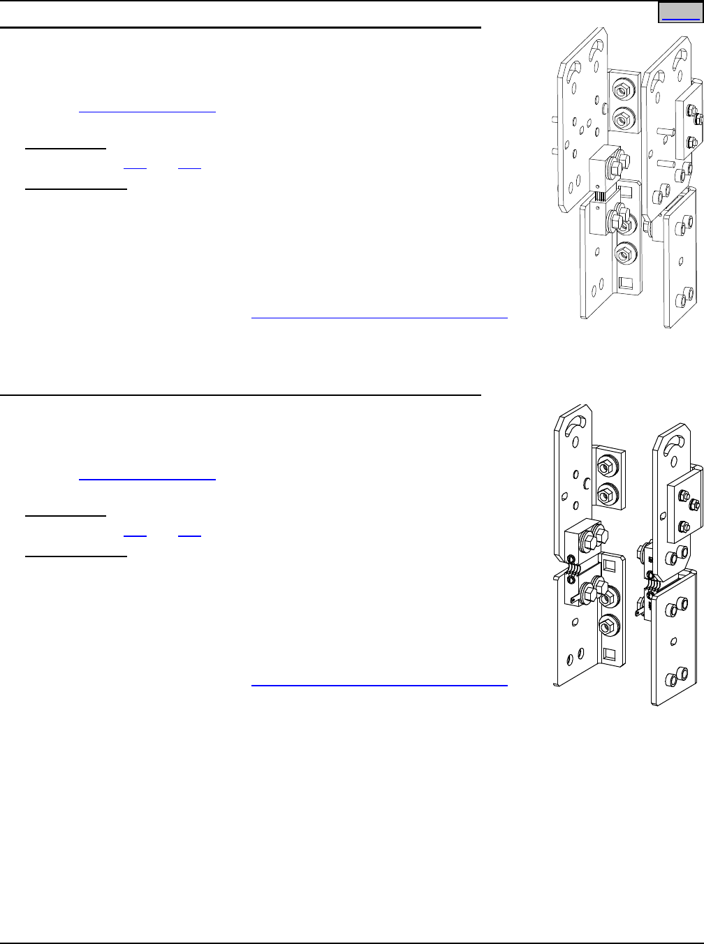
List 145: Bay Input Feed and Shunt Assembly (2 Cables, 50 mV. Shunts)
Features
♦ Provides landing points for two (2) input leads (on each side).
♦ Provides an 800A, 50mV shunt (both sides).
♦ Can be rotated for top or bottom feed configurations.
♦ See DC Input Connections under Wiring Illustrations in ACCESSORY
DESCRIPTIONS for input termination specifications.
Restrictions
For use in Lists 105 and 107 only.
Ordering Notes
1) Order as required. Each List 145 provides input terminations and shunts for
both sides.
For top and bottom feed 2-load applications, order one (1) List 145 and specify
top or bottom feed.
For top and bottom feed multi-load applications, order one (1) List 145 for each
Side A/Side B load and specify top or bottom feed.
2) Order input lugs as required per DC Input Cable Sizes and Lugs Selection
under Wiring Notes in ACCESSORY DESCRIPTIONS.
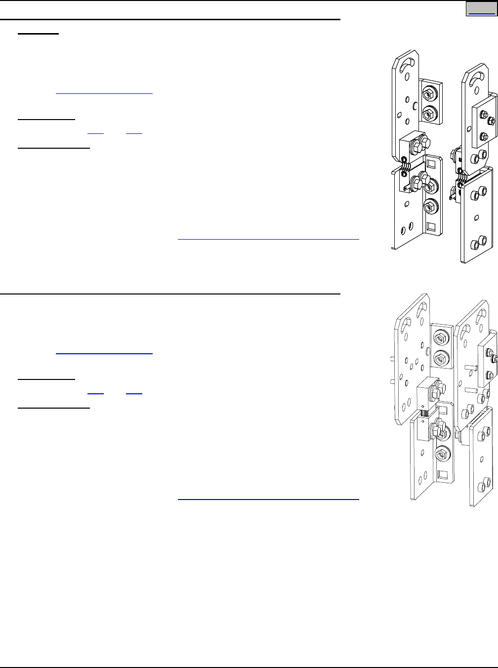
List 147: Bay Input Feed and Shunt Assembly (4 Cables, 50 mV. Shunts)
♦ Provides landing points for four (4) input leads (on each side).
♦ Provides an 800A, 50mV shunt (one per side).
♦ Can be rotated for top or bottom feed configurations.
♦ See DC Input Connections under Wiring Illustrations in ACCESSORY
DESCRIPTIONS for input termination specifications.
Restrictions
For use in Lists 105 and 107 only.
Ordering Notes
1) Order as required. Each List 147 provides input terminations and shunts for
both sides.
For top and bottom feed 2-load applications, order one (1) List 147 and specify
top or bottom feed.
For top and bottom feed multi-load applications, order one (1) List 147 for each
Side A/Side B load and specify top or bottom feed.
2) Order input lugs as required per DC Input Cable Sizes and Lugs Selection
under Wiring Notes in ACCESSORY DESCRIPTIONS.
Home
SAG582120600 System Application Guide
Issue BF, February 21, 2014 Spec. No. 582120600 (Model 801DB NVGB)
Page 20 of 72
This document is property of Emerson Network Power, Energy Systems, North America, Inc. and contains confidential and proprietary information owned by Emerson Network Power, Energy
Systems, North America, Inc. Any copying, use, or disclosure of it without the written permission of Emerson Network Power, Energy Systems, North America, Inc. is strictly prohibited.
J1
J1
Adapter supplied with
panels E/W TPL fuses
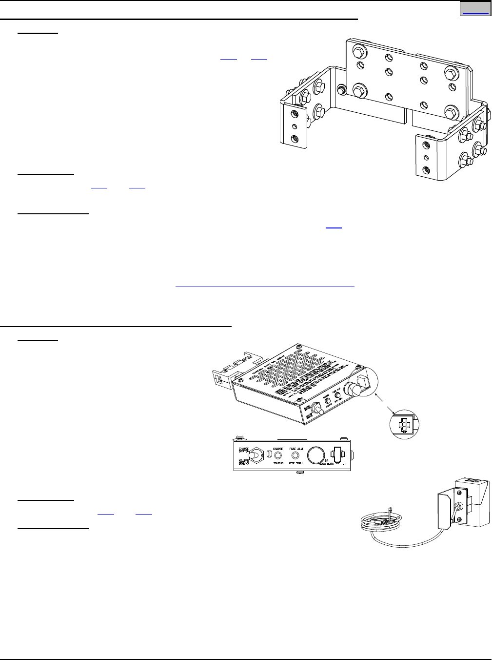
List 148: 2400A Ground/Return Input Assembly, with Optional Bonding Strap
Features
♦ Provides additional landing points for ground/return
input leads (both sides) to the optional List 116 or 126
Internal Ground/Return Bar.
♦ Increases Ground/Return Bar rating from 1200A to
2400A.
♦ Each List 148 provides two (2) Input Lug Landing
Plate Assemblies (one per side).
♦ Included is an optional bonding strap for connecting
both Ground/Return Bars together for any current
requirement up to 2400A.
Restrictions
For use with List 116 and 126 Internal Ground/Return
Bars only.
Ordering Notes
1) List 116 and 126 internal return bars are rated for 1200 Amps. List 148 is available to increase that
capacity to 2400 Amps and provide additional cable landing points. Each bay can accommodate (1) List
148. List 148 offers cable termination at the rear of the bay and the option of a bonding strap. Mounting
location (top or bottom) of List 148 will be opposite that specified for the Input Lug Landing Plate
Assemblies of List 116 or 126.
2) Order input lugs as required per DC Input Cable Sizes and Lugs Selection under Wiring Notes in
ACCESSORY DESCRIPTIONS.
List 150: Optional Capacitor Precharge Assembly
Features
♦ Portable hand-held unit.
♦ Allows capacitors of a DC load to be
initially charged before a TLS/TPS or
TPL distribution fuse is inserted. This
prevents the fuse from possibly
blowing open as it is inserted due to
high capacitor charging current.
♦ Designed to plug directly into a
TLS/TPS type fuseholder case. An
adapter is supplied which plugs
directly into a TPL type fuseholder
case.
Restrictions
For Use with Lists 110 and 120 only.
Ordering Notes
1) Order as required.
Home
System Application Guide SAG582120600
Spec. No. 582120600 (Model 801DB NVGB) Issue BF, February 21, 2014
Page 21 of 72
This document is property of Emerson Network Power, Energy Systems, North America, Inc. and contains confidential and proprietary information owned by Emerson Network Power, Energy
Systems, North America, Inc. Any copying, use, or disclosure of it without the written permission of Emerson Network Power, Energy Systems, North America, Inc. is strictly prohibited.
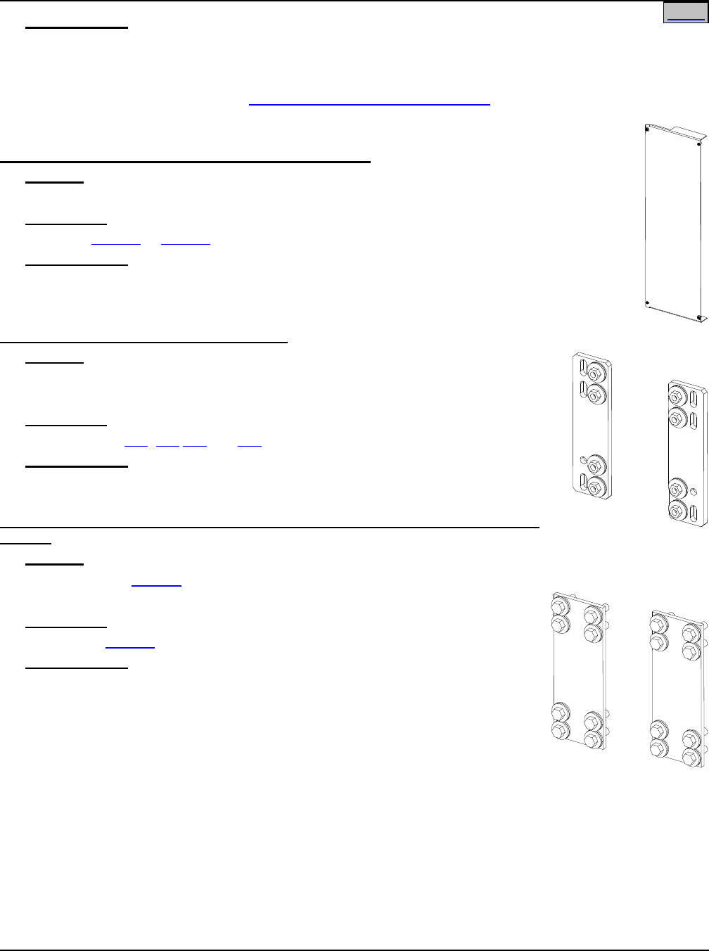
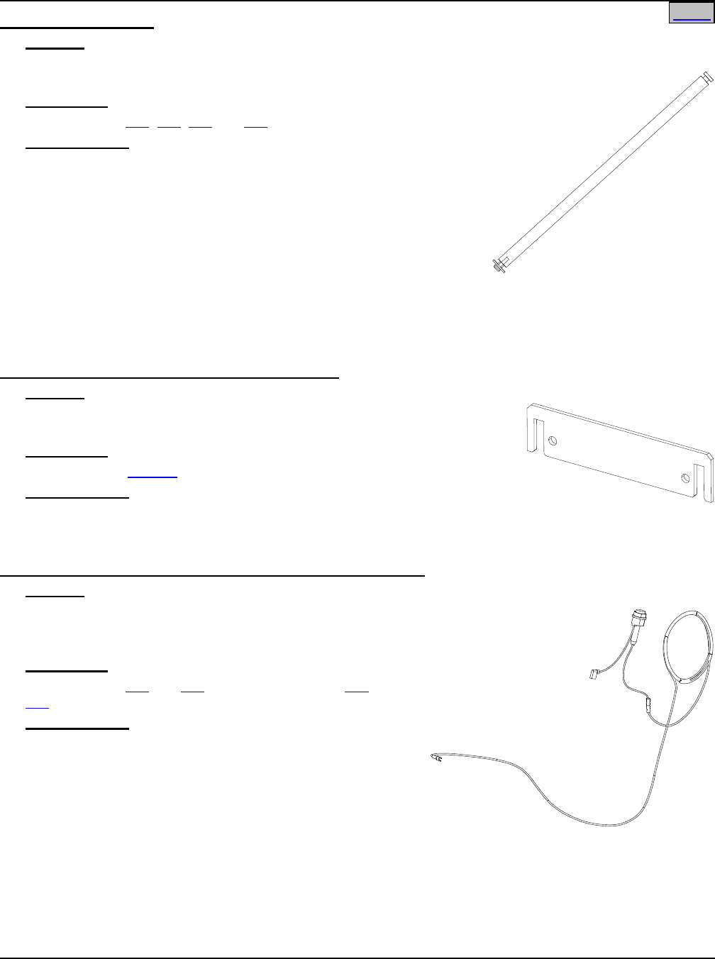
List 151: Dressing Bar
Features
♦ Provides adjustable grooming bar to allow customer to dress output
load cables along the sides of the bay.
Restrictions
For use in Lists 105, 106, 107 and 108.
Ordering Notes
1) Order dressing bars as required.
2) Maximum of eight (8) dressing bars to be ordered for an eight (8)
panel bay (List 105 or 108).
3) Maximum of six (6) dressing bars to be ordered for a six (6) panel
bay (List 106 and 107).
4) Additional dressing bars may be ordered when using boxframe
extensions.
Maximum of four (4) additional dressing bars to be ordered when using the two foot (2’) extension.
Maximum of six (6) additional dressing bars to be ordered when using the four and one-half foot (4-1/2’)
extension.
List 153: Load Distribution Cable Management Kit
Features
♦ Provides Twelve (12) Cable Separators (P/N 541543) plus cable ties as
a ‘Method to Manage Wiring’.
Restrictions
Not for use with List 151.
Ordering Notes
1) Order one (1) kit per bay. Order an additional kit if Box Framework
Extensions are ordered.
List 156: Meter and Alarm Card Internal Power In-Line Fuse Kit
Features
♦ The In-Line Fuse Kit is a field installable option that
allows internally powered meter and alarm circuits vs.
external powered meter and alarm circuits.
Restrictions
For use in Lists 105 and 107. Not required for List 106 and
108.
Ordering Notes
1) One (1) required for base installation. Order two (2) if
bay is equipped with two (2) or more isolated loads.
2) In-Line fuse kit comes furnished with a 3 amp fuse. If
additional replacement fuses required, order Part No.
101014.
Home
SAG582120600 System Application Guide
Issue BF, February 21, 2014 Spec. No. 582120600 (Model 801DB NVGB)
Page 22 of 72
This document is property of Emerson Network Power, Energy Systems, North America, Inc. and contains confidential and proprietary information owned by Emerson Network Power, Energy
Systems, North America, Inc. Any copying, use, or disclosure of it without the written permission of Emerson Network Power, Energy Systems, North America, Inc. is strictly prohibited.
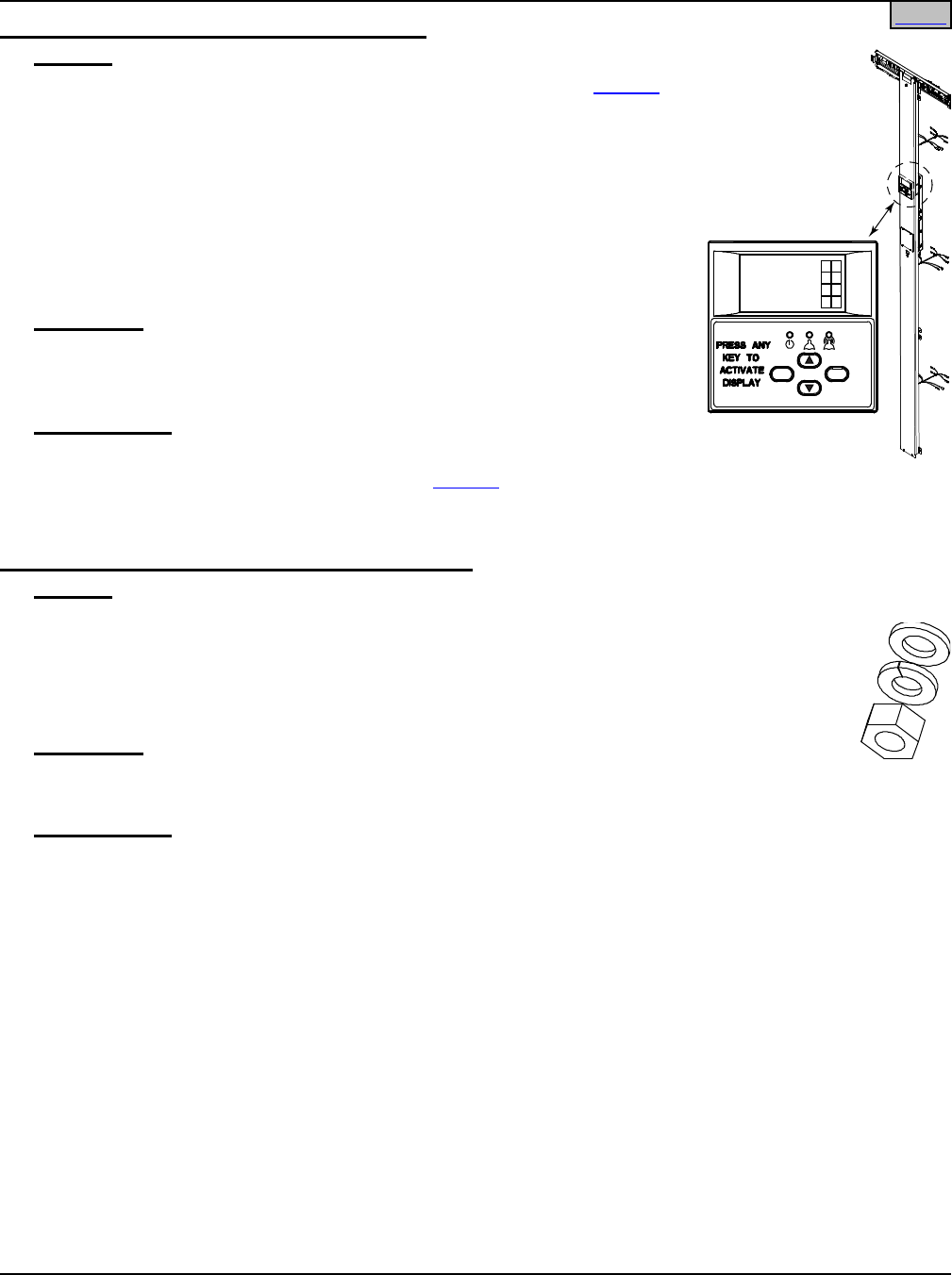
List 166: Meter Panel Field Upgrade Retrofit Kit
Features
♦ Provides components to replace the standard meter panel in a List 107
bay with the Advanced Meter/Alarm Panel.
♦ Includes an Advanced Meter/Alarm Panel that provides the following
functions for each panel in the bay: voltage and current metering and
Low Voltage, Power Lost, Overcurrent, and Fuse/Circuit Breaker alarms.
Also provided are four (4) external alarm relay circuits, to which any
combination of alarms can be mapped.
♦ Provides four (4) fused auxiliary -48V power outputs (1-1/3A), fused
remote (A/B) meter panel inputs, internal/external sense option, and an
Ethernet connection (requires List 170 Ethernet option).
Restrictions
Upgrades List 107 only.
Original 50mV load shunts must be replaced with 25mV shunts. Six (6) 25mV
shunts (P/N 545619) are included in List 166.
Ordering Notes
1) Order one (1) List 166 to upgrade one (1) List 107.
2) For remote access capability, order one (1) List 170 Ethernet option.
3) For installation, contact Emerson Network Power Installation Services Group at 800-800-1280.
List 167: Pre-Installed Load Lug-Mounting Hardware
Features
♦ Provides all required 1/4” flat washers, 1/4” lock washers and 1/4-20 hex nuts for connecting
customer-furnished lugs to all Load distribution positions in a bay.
♦ If internal full-length ground/return bars (List 116 or 126) are ordered, List 167 will also
include all required ¼” lug-mounting hardware for all Load Return positions.
♦ Hardware is pre-installed on lug-landing studs.
Restrictions
Does not provide input lug hardware.
Does not provide lug hardware for panel length ground/return bars (List 117, 127).
Ordering Notes
1) Order one (1) List 167 to provide pre-installed hardware on all load distribution lug positions and all full-
length ground/return bar lug positions present in the bay you are ordering.
ESC ENT
SYSTEM OK
52.09V
1492A
A 52.09V 210A B 52.9V
Home
System Application Guide SAG582120600
Spec. No. 582120600 (Model 801DB NVGB) Issue BF, February 21, 2014
Page 23 of 72
This document is property of Emerson Network Power, Energy Systems, North America, Inc. and contains confidential and proprietary information owned by Emerson Network Power, Energy
Systems, North America, Inc. Any copying, use, or disclosure of it without the written permission of Emerson Network Power, Energy Systems, North America, Inc. is strictly prohibited.
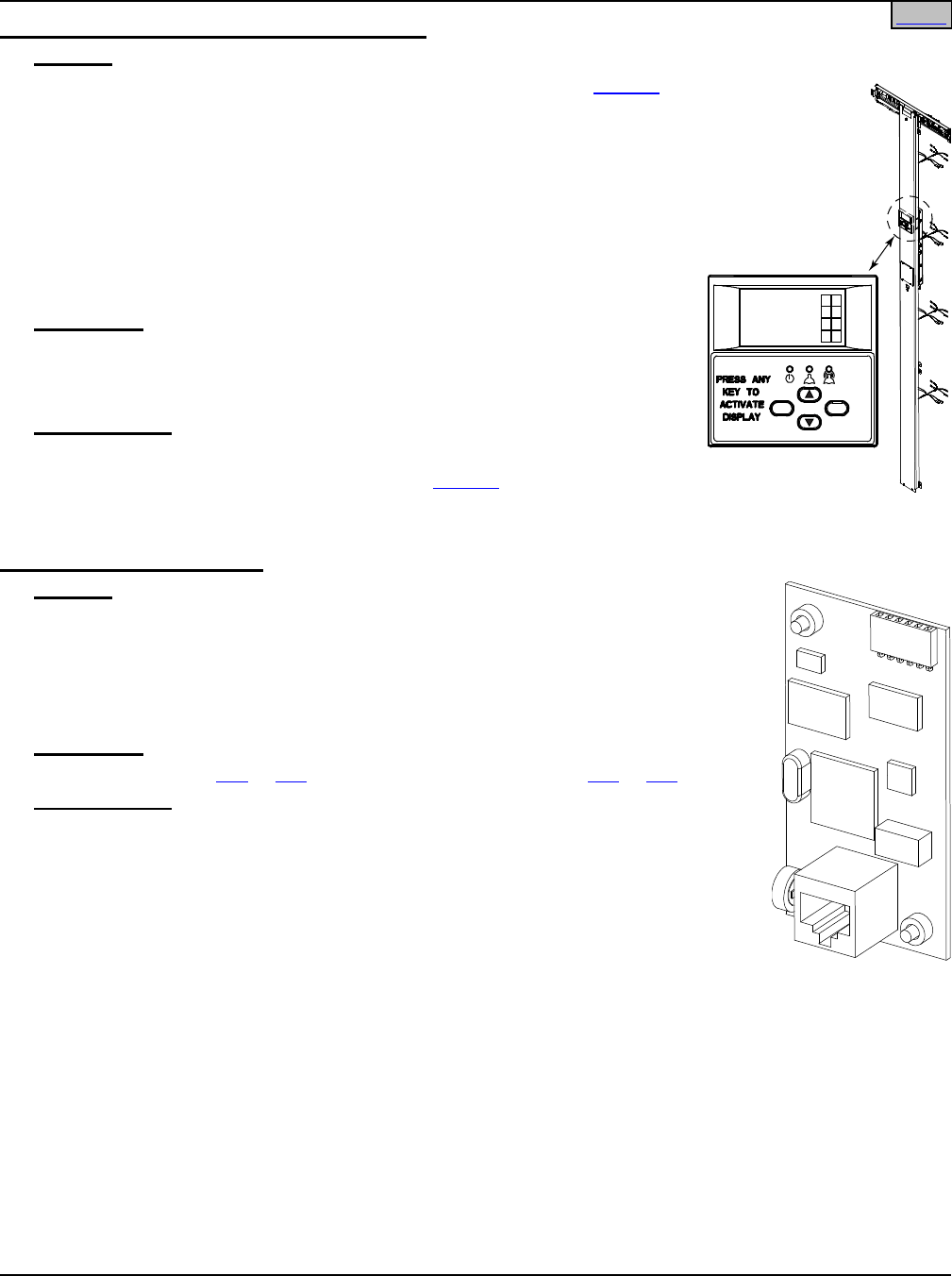
List 168: Meter Panel Field Upgrade Retrofit Kit
Features
♦ Provides components to replace the standard meter panel in a List 105
bay with the Advanced Meter/Alarm Panel.
♦ Includes an Advanced Meter/Alarm Panel that provides the following
functions for each panel in the bay: voltage and current metering and
Low Voltage, Power Lost, Overcurrent, and Fuse/Circuit Breaker alarms.
Also provided are four (4) external alarm relay circuits, to which any
combination of alarms can be mapped.
♦ Provides four (4) fused auxiliary -48V power outputs (1-1/3A), fused
remote (A/B) meter panel inputs, internal/external sense option, and an
Ethernet connection (requires List 170 Ethernet option).
Restrictions
Upgrades List 105 only.
Original 50mV load shunts must be replaced with 25mV shunts. Eight (8)
25mV shunts (P/N 545619) are included in List 168.
Ordering Notes
1) Order one (1) List 168 to upgrade one (1) List 105.
2) For remote access capability, order one (1) List 170 Ethernet option.
3) For installation, contact Emerson Network Power Installation Services Group at 800-800-1280.
List 170: Assembly, Ethernet
Features
♦ Provides comprehensive remote monitoring, control, and data processing
functions for a BDFB equipped with the Advanced Meter/Alarm Panel via an
Ethernet port.
♦ Access is by means of a Web Interface.
♦ Requires a PC equipped with an Ethernet card and Internet Explorer.
Restrictions
For use only with List 106 or 108 bays, or bays retrofitted with List 166 or 168.
Ordering Notes
1) Order as required.
ESC ENT
SYSTEM OK
52.09V
1492A
A 52.09V 210A B 52.9V
Home

SAG582120600 System Application Guide
Issue BF, February 21, 2014 Spec. No. 582120600 (Model 801DB NVGB)
Page 24 of 72
This document is property of Emerson Network Power, Energy Systems, North America, Inc. and contains confidential and proprietary information owned by Emerson Network Power, Energy
Systems, North America, Inc. Any copying, use, or disclosure of it without the written permission of Emerson Network Power, Energy Systems, North America, Inc. is strictly prohibited.
For Manufactured Discontinued Bays (Model 1293V3)
See Issue AR SAG582120600 for List Descriptions.
THE LIST OPTIONS REFLECTED IN SAG582120600 ISSUE AR
CANNOT BE USED IN THE CURRENT DESIGN BAY (MODEL 801DB NVGB)
THESE LIST OPTIONS CANNOT BE USED IN THE
CURRENT DESIGN BAY (MODEL 801DB NVGB)
FOR MANUFACTURER DISCONTINUED BAYS (MODEL 1293V3)
Distribution Bus Modules
List
Number
Part
Number Description
-- -- 8 Panel Bay TLS/TPS-Type Fuseholders (3-70A)
e/w Internal Grounding.
20G 58212060020G 6 Panel Bay
15 58212060015 8 Panel Bay Bullet Nose-Type Circuit Breakers or Bullet Nose-Type
TLS/TPS Fuseholders (1-100A), or a combination of both.
(Snap-In Blank Distribution Position Cover: P/N 387454200.)
25 58212060025 6 Panel Bay
10 58212060010 8 Panel Bay TLS/TPS-Type Fuseholders (3-70A)
20 See Notes 6 Panel Bay
Notes:
Remove the ground bar from a List 20G for a List 20 replacement.
A List 150 can be used to replace a List 50.
A List 156 can be used to replace a List 56.
Home Home

System Application Guide SAG582120600
Spec. No. 582120600 (Model 801DB NVGB) Issue BF, February 21, 2014
Page 25 of 72
This document is property of Emerson Network Power, Energy Systems, North America, Inc. and contains confidential and proprietary information owned by Emerson Network Power, Energy
Systems, North America, Inc. Any copying, use, or disclosure of it without the written permission of Emerson Network Power, Energy Systems, North America, Inc. is strictly prohibited.
THESE LIST OPTIONS CANNOT BE USED IN THE
CURRENT DESIGN BAY (MODEL 801DB NVGB)
FOR MANUFACTURER DISCONTINUED BAYS (MODEL 1293V3)
Distribution Bus Module Paralleling Options
To Parallel This List
W
I
T
H
This List
Order
Paralleling
Option List
Purchased
Before 6/30/00
Purchased
After 6/30/00
Purchased
Before 6/30/00
Purchased
After 6/30/00
10, 11, 12, or 14 -- 10, 11, 12, or 14 -- 30, 35
20, 21, 22, or 24 -- 20, 21, 22, or 24 -- 31, 36
15 -- 15 -- 35 or 37
25 -- 25 -- 36 or 38
-- 10, 11, 12, 14, or 15 -- 10, 11, 12, 14, or 15 35 or 37
-- 13 -- 13 35 or 37
-- 20, 20G, 21, 22, 24,
or 25
-- 20, 20G, 21, 22, 24,
or 25
36 or 38
--
23
--
23
36 or 38
15
--
--
10, 11, 12, 14, or 15
35 or 37
25 -- --
20, 20G, 21, 22, 24,
or 25 36 or 38
10, 11, 12,
or 14
-- -- 10, 11, 12,
or 14
30*, 35
20, 21, 22,
or 24 -- --
20, 20G, 21, 22,
or 24 31*, 36
10, 11, 12, or 14 -- 15 -- NONE
20, 21, 22, or 24 -- 25 -- NONE
10, 11, 12, or 14 -- -- 15 NONE
20, 21, 22, or 24 -- -- 25 NONE
Notes: Total load for all paralleled distribution bus modules is limited to 640 amperes, maximum.
List 35 and 36 provide multiple load shunts.
List 30, 31, 37, and 38 provide a single load shunt.
* Requires additional components,
see Lists 30 and 31 Ordering Notes
in Issue AR SAG582120600.
Home
SAG582120600 System Application Guide
Issue BF, February 21, 2014 Spec. No. 582120600 (Model 801DB NVGB)
Page 26 of 72
This document is property of Emerson Network Power, Energy Systems, North America, Inc. and contains confidential and proprietary information owned by Emerson Network Power, Energy
Systems, North America, Inc. Any copying, use, or disclosure of it without the written permission of Emerson Network Power, Energy Systems, North America, Inc. is strictly prohibited.
ACCESSORY DESCRIPTIONS
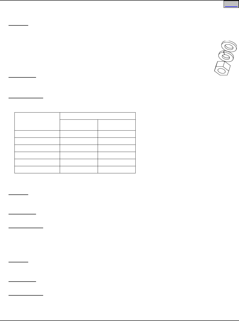
Load Lug Hardware Kits
Features
♦ These kits provide hardware for connecting customer-furnished Load and Load Return (internal full-length
ground bar only) lugs.
• Part No. 547682 kit provides (35) each of 1/4” flat washers, 1/4” lock washers and 1/4-
20 hex nuts.
• Part No. 547683 kit provides (60) each of 1/4” flat washers, 1/4” lock washers and 1/4-
20 hex nuts.
♦ All hardware is shipped loose in bags.
Restrictions
Does not provide input lug hardware.
Does not provide lug hardware for panel length ground/return bars (List 117, 127).
Ordering Notes
1) Order as required. The table shows the quantity required for each assembly.
For Each of the
Following List
Numbers Ordered
Order This Kit Quantity
Kit P/N 547682 Kit P/N 547683
110 0 N/A
115 1 N/A
116 8 N/A
120 N/A 0
125 N/A 1
126 N/A 6
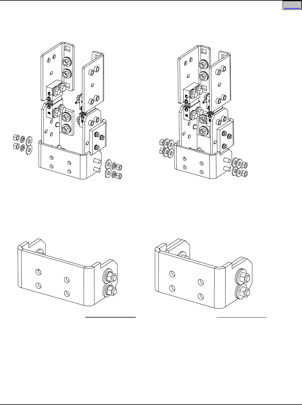
Side by Side Busbar Link Kit for Use with List 110 and List 120, P/N 556103
Features
♦ Connects each side of a List 143 or List 144 together, side by side, in a List 106 or List 108 bay using List
120 or List 110 distribution panels. Provides two positions to terminate up to four (4) 750 MCM cables.
Restrictions
For use with List 106 with List 120 and List 108 with List 110.
Ordering Notes
1) Order P/N 556103 for List 143 or List 144 as required (see restrictions above and illustration on next
page).
Side by Side Busbar Link Kit for Use with List 115 and List 125, P/N 557256
Features
♦ Connects each side of a List 143 or List 144 together, side by side, in a List 106 or List 108 bay using List
125 or List 115 distribution panels. Provides two positions to terminate up to four (4) 750 MCM cables.
Restrictions
For use with List 106 with List 125 and List 108 with List 115.
Ordering Notes
1) Order P/N 557256 for List 143 or List 144 as required (see restrictions above and illustration on next
page).
Home
System Application Guide SAG582120600
Spec. No. 582120600 (Model 801DB NVGB) Issue BF, February 21, 2014
Page 27 of 72
This document is property of Emerson Network Power, Energy Systems, North America, Inc. and contains confidential and proprietary information owned by Emerson Network Power, Energy
Systems, North America, Inc. Any copying, use, or disclosure of it without the written permission of Emerson Network Power, Energy Systems, North America, Inc. is strictly prohibited.
Home
582120600 List 144
(List 143 Similar)
when used with List 110 and List 120
556103
582120600 List 144
(List 143 Similar)
when used with List 115 and List 125
557256
Hardware Build Up
3/8-16 x 1-1/4” Bolt
3/8” Flat Washer
Busbar Link
3/8” Flat Washer
3/8” Lock Washer
3/8-16 Nut
Hardware Build Up
3/8-16 x 1-1/2” Bolt
3/8” Flat Washer
Busbar Link Spacer
Busbar Link
3/8” Flat Washer
3/8” Belleville Lock Washer
3/8-16 Nut
556103 557256
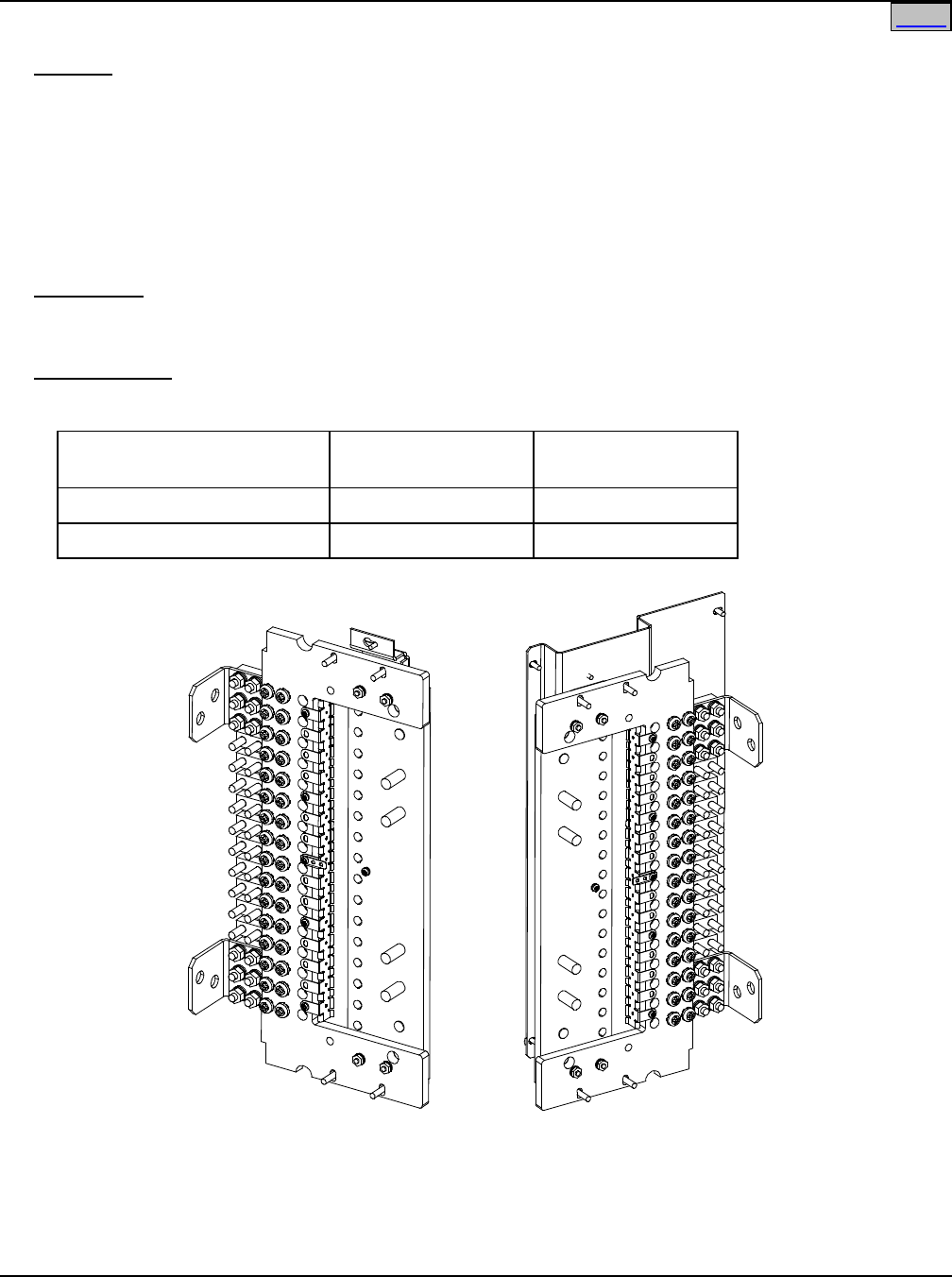
SAG582120600 System Application Guide
Issue BF, February 21, 2014 Spec. No. 582120600 (Model 801DB NVGB)
Page 28 of 72
This document is property of Emerson Network Power, Energy Systems, North America, Inc. and contains confidential and proprietary information owned by Emerson Network Power, Energy
Systems, North America, Inc. Any copying, use, or disclosure of it without the written permission of Emerson Network Power, Energy Systems, North America, Inc. is strictly prohibited.
Home
Right Angle Lug Adaptor Kits, P/Ns 556377 and 556378
Features
♦ These kits allow for load connections to the List 115, 116, 125, and 126 panels at right angle to the
standard connection and also allows for use of up to 4/0 AWG wire. The lug adapters are designed for
use with 2-hole lugs with 3/8” clearance holes on 1” centers. The lug adapters permit installation of
cables back to back.
♦ Part No. 556377 provides one (1) busbar P/N 555918, six (6) 1/4” flat washers P/N 214110100, six (6)
1/4” split lock washers P/N 215111100, and six (6) 1/4-20 hex nuts P/N 228557100.
♦ Part No.556378 provides one (1) busbar P/N 555919, six (6) 1/4” flat washers P/N 214110100, six (6)
1/4” split lock washers P/N 215111100, and six (6) 1/4-20 hex nuts P/N 228557100.
Restrictions
For use with lists 115,116,125 and 126.
For use with three-pole circuit breaker or 3-pole ground/return only.
Ordering Notes
1) Order as required. Refer to the following table.
Application for
Right Angle Adaptors
Left Side
(viewed from rear)
Right Side
(viewed from rear)
Top Feed Application P/N 556378 P/N 556377
Bottom Feed Application P/N 556377 P/N 556378
582120600 List 115
(some components
not shown for clarity only)
582120600 List 115
P/N 556377
Right Angle
Lug Adapter Kit
P/N 556377
Right Angle
Lug Adapter Kit
P/N 556378
Right Angle
Lug Adapter Kit
P/N 556378
Right Angle
Lug Adapter Kit
rear rear
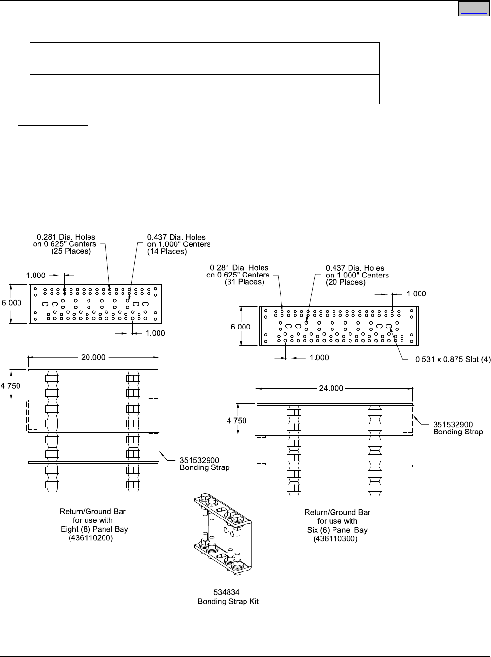
System Application Guide SAG582120600
Spec. No. 582120600 (Model 801DB NVGB) Issue BF, February 21, 2014
Page 29 of 72
This document is property of Emerson Network Power, Energy Systems, North America, Inc. and contains confidential and proprietary information owned by Emerson Network Power, Energy
Systems, North America, Inc. Any copying, use, or disclosure of it without the written permission of Emerson Network Power, Energy Systems, North America, Inc. is strictly prohibited.
External Return/Ground Bar Assemblies
Return/Ground Bar Assemblies
8 Panel Bay Return/Ground Bar Assembly 436110200
6 Panel Bay Return/Ground Bar Assembly 436110300
Bonding Strap Kit 534834
Ordering Notes
1) Order Return/Ground Bar Assembly(s) as required. One (1) per bay provides landing positions for each
fuse position in the bay assuming that cables are terminated back to back. If individual termination is
required, order two (2) per bay.
2) Order Bonding Strap Kit as required. Bonding Strap Kit includes one strap (P/N 351532900) plus
hardware.
3) Order input return lugs (two hole, 1/4" bolt clearance hole, 0.625" centers; or two hole, 3/8" bolt clearance
hole, 1" centers) as required.
Home
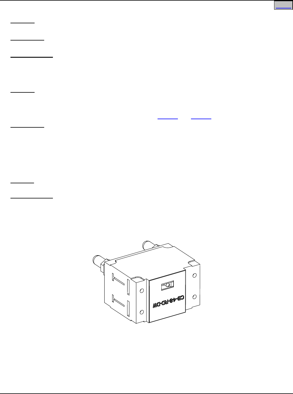
SAG582120600 System Application Guide
Issue BF, February 21, 2014 Spec. No. 582120600 (Model 801DB NVGB)
Page 30 of 72
This document is property of Emerson Network Power, Energy Systems, North America, Inc. and contains confidential and proprietary information owned by Emerson Network Power, Energy
Systems, North America, Inc. Any copying, use, or disclosure of it without the written permission of Emerson Network Power, Energy Systems, North America, Inc. is strictly prohibited.
Seismic Anchor Kit, P/N 545387
Features
♦ Provides four (4) Relay Rack Seismic Mounting Anchors, P/N 216821200.
Restrictions
For use with Lists 105, 106, 107 and 108.
Ordering Notes
1) Order Seismic Anchor Kit P/N 545387 as required.
Transient Voltage Surge Suppressor (TVSS) Device
Features
♦ When properly grounded, the device(s) suppresses transient voltages that are above 60 VDC.
♦ Contains an indicator which lights when circuit has activated to suppress voltages.
♦ Plugs into distribution device mounting positions of a List 115 and List 125 Distribution Panel.
Restrictions
To be used with Distribution Panels List 115 and List 125 only.
All unparalleled Distribution Panels require a TVSS Device, only one (1) TVSS Device required per paralleled
groups of Distribution Panels.
Unless otherwise specified, install the TVSS Device in the mounting position closest to the Distribution
Panel’s input busbar.
Wire to be sized so that the maximum wire resistance is less than 0.550 milliohms.
Caution: The TVSS Device occupies two mounting positions. Leave an additional empty mounting
position between the TVSS Device and any overcurrent protective device.
Ordering Notes
1) Order kit P/N 520401 (includes TVSS Device P/N 122201 plus lug mounting hardware) as required.
Customer to supply grounding lead(s) with lugs to connect from TVSS Device(s) into customer's
grounding network.
Home Home
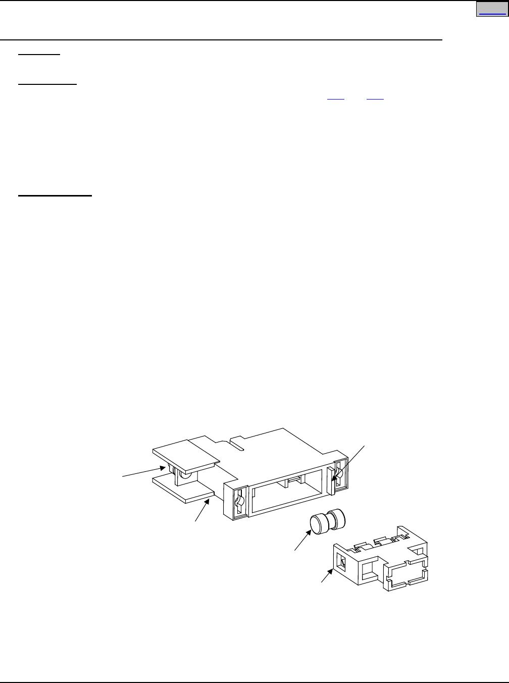
System Application Guide SAG582120600
Spec. No. 582120600 (Model 801DB NVGB) Issue BF, February 21, 2014
Page 31 of 72
This document is property of Emerson Network Power, Energy Systems, North America, Inc. and contains confidential and proprietary information owned by Emerson Network Power, Energy
Systems, North America, Inc. Any copying, use, or disclosure of it without the written permission of Emerson Network Power, Energy Systems, North America, Inc. is strictly prohibited.
Distribution Devices and Lug Selection
TLS/TPS Fuses/Fuseblocks, TPL Fuses/Fuseblocks, and Lug Selection for Lists 110 and 120
Features
♦ Each fuse installs into the respective fuseblock.
Restrictions
The fuses and fuseblocks specified in this section are for use in Lists 110 and 120.
Load should not exceed 80% of device rating.
Distribution Panel capacity is 640A maximum continuous.
TLS/TPS Fuseblock: Maximum lug width is 0.750”.
Maximum wire size is 2 AWG.
TPL Fuseblock: Maximum lug width is 1.8”.
Maximum wire size is 2/0 AWG.
Ordering Notes
1) A List 110 has twelve (12) fuse positions and a List 120 has twenty (20) fuse positions. The fuse panel
can be populated with TLS/TPS fuseblocks (requires one [1] fuse position), TPL fuseblocks (requires two
[2] fuse positions), or a combination of TLS/TPS and TPL fuseblocks.
List 110 includes (12) TLS/TPS Fuseblocks P/N 248817100, and List 120 includes (20) TLS/TPS
Fuseblocks P/N 248817100. For panels factory configured in a bay, each TPL Fuseblock P/N 516241
ordered replaces (2) P/N 248817100 Fuseblocks. For fuse panels shipped separately, the TLS/TPS
fuseblocks are factory installed and if TPL fuseblocks are required they will have to be installed in the
field.
Order fuses and fuseblocks as required per Table 1 and Table 3.
For each TLS/TPS fuseblock ordered, also order one (1) P/N 248610301 alarm fuse and one (1) P/N
248898700 safety fuse cover. The alarm fuse and safety fuse cover is provided with a TPL fuseblock.
2) See Table 2 and Table 4 for recommended load lugs. For other available lugs and hardware, refer to
drawings 031110100 through 031110300.
3) See Table 8 and Table 9 for recommended load distribution wire sizes.
TLS/TPS Fuse
Fuseblock
(P/N 248817100)
Fuse Case
GMT-18/100A Alarm Fuse
(P/N 248610301) and
GMT-X Safety Fuse Cover
(P/N 248898700)
(Both ordered separately)
Lists 110 and 120 TLS/TPS Fuseblock
1/4 -20 swage studs
for installation of customer
provided single hole lugs
Max. Lug Width 0.750".
Max. Wire Size 2 AWG.
Home
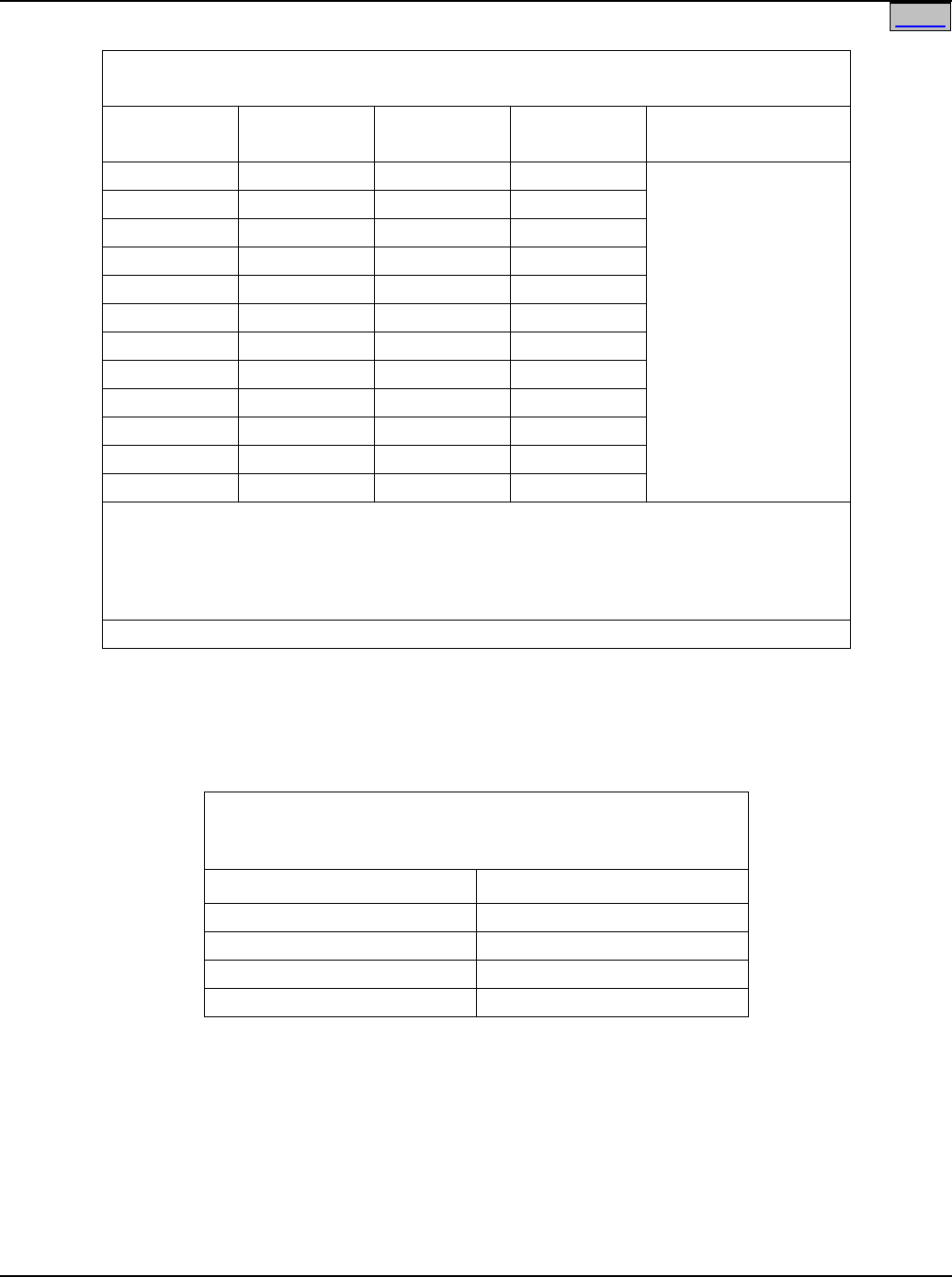
SAG582120600 System Application Guide
Issue BF, February 21, 2014 Spec. No. 582120600 (Model 801DB NVGB)
Page 32 of 72
This document is property of Emerson Network Power, Energy Systems, North America, Inc. and contains confidential and proprietary information owned by Emerson Network Power, Energy
Systems, North America, Inc. Any copying, use, or disclosure of it without the written permission of Emerson Network Power, Energy Systems, North America, Inc. is strictly prohibited.
TLS/TPS Fuses and Fuseblocks
for Use in Lists 110 and 120
Ampere
Rating P/N Bussmann
P/N
Littelfuse
P/N
Lugs for Fuseblock
P/N 248817100
3
248230900
TPS-3
TLS003
See Table 2
5
248231000
TPS-5
TLS005
6
248231200
TPS-6
TLS006
10
248231500
TPS-10
TLS010
15
248231800
TPS-15
TLS015
20
248232100
TPS-20
TLS020
25
248232400
TPS-25
TLS025
30
248232700
TPS-30
TLS030
40
248233300
TPS-40
TLS040
50
248233900
TPS-50
TLS050
60
248234200
TPS-60
TLS060
70
248234500
TPS-70
TLS070
Each fuse requires (1) Fuseblock P/N 248817100.
See “Ordering Notes” in this section.
For each fuseblock ordered, also order...
(1) P/N 248610301 alarm fuse (GMT-18/100A), and
(1) P/N 248898700 safety fuse cover (GMT-X).
See Table 8 for recommended load distribution wire sizes.
Table 1
TLS/TPS Fuses and Fuseblocks
for Use in Lists 110 and 120
Lugs for Use with Fuseblock P/N 248817100
Used in Lists 110 and 120 Distribution Panels
(single hole, 1/4” bolt clearance hole)
Lead Size (AWG) P/N
8
245350400
6
245350600
4
245350700
2
245350800
Note: Cables larger than 2 AWG require an H-TAP connection.
Table 2
Lugs for Use with Fuseblock P/N 248817100
Used in Lists 110 and 120
Home
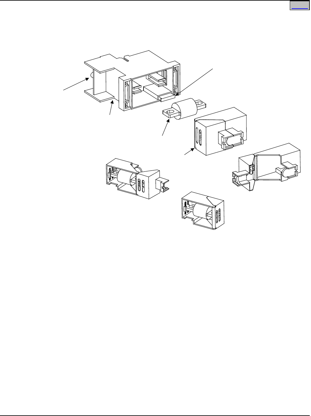
System Application Guide SAG582120600
Spec. No. 582120600 (Model 801DB NVGB) Issue BF, February 21, 2014
Page 33 of 72
This document is property of Emerson Network Power, Energy Systems, North America, Inc. and contains confidential and proprietary information owned by Emerson Network Power, Energy
Systems, North America, Inc. Any copying, use, or disclosure of it without the written permission of Emerson Network Power, Energy Systems, North America, Inc. is strictly prohibited.
Fuse Case
Open Fuse Case View
TPL Fuse
Fuse Installed in
Open Fuse Case
Fuse Installed in
Closed Fuse Case
Lists 110 and 120 TPL Fuseblock
5/16-18 swage studs
for installation of customer
provided single hole lugs.
Max. Lug Width 1.8".
Max. Wire Size 2/0 AWG. Fuseblock
(P/N 516241)
GMT-18/100A Alarm Fuse
(P/N 248610301) and
GMT-X Safety Fuse Cover
(P/N 248898700)
(Both are provided
w/ fuseblock)
Home
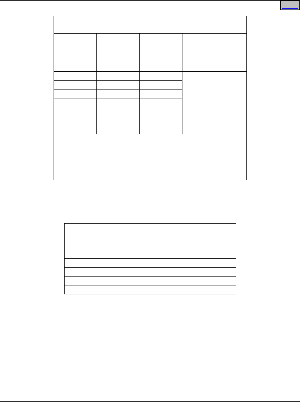
SAG582120600 System Application Guide
Issue BF, February 21, 2014 Spec. No. 582120600 (Model 801DB NVGB)
Page 34 of 72
This document is property of Emerson Network Power, Energy Systems, North America, Inc. and contains confidential and proprietary information owned by Emerson Network Power, Energy
Systems, North America, Inc. Any copying, use, or disclosure of it without the written permission of Emerson Network Power, Energy Systems, North America, Inc. is strictly prohibited.
TPL Fuses and Fuseblock
for Use in Lists 110 and 120
Ampere
Rating
Required
Distribution
Bus
Mounting
Positions
P/N Lugs for Fuseblock
P/N 516241
70
2
248251500
See Table 4
80 2 248252000
100
2
248252600
150
2
248253300
200 2 248254000
225
2
248254500
250
2
248255000
Each fuse requires (1) Fuseblock P/N 516241.
See “Ordering Notes” in this section.
Fuseblock P/N 516241 also includes...
(1) P/N 248610301 alarm fuse (GMT-18/100A), and
(1) P/N 248898700 safety fuse cover (GMT-X).
See Table 9 for recommended load distribution wire sizes.
Table 3
TPL Fuses and Fuseblock
for Use in Lists 110 and 120 Distribution Panels
Lugs for Use with Fuseblock P/N 516241
Used in Lists 110 and 120 Distribution Panels
(single hole, 5/16” bolt clearance hole)
Lead Size (AWG) P/N
6 245351380
4
245351390
2
245351400
1 120224
Note: Cables larger than 2/0 AWG require an H-TAP connection.
Table 4
Lugs for Use with Fuseblock P/N 516241
Used in Lists 110 and 120 Distribution Panels
Home

System Application Guide SAG582120600
Spec. No. 582120600 (Model 801DB NVGB) Issue BF, February 21, 2014
Page 35 of 72
This document is property of Emerson Network Power, Energy Systems, North America, Inc. and contains confidential and proprietary information owned by Emerson Network Power, Energy
Systems, North America, Inc. Any copying, use, or disclosure of it without the written permission of Emerson Network Power, Energy Systems, North America, Inc. is strictly prohibited.
Bullet Nose-Type Circuit Breakers, Bullet Nose-Type Fuseblocks e/w TLS/TPS Fuses, and Lug
Selection for Lists 115 and 125
Features
♦ Each circuit breaker plugs into one, two or three distribution device mounting position(s).
♦ A single fuseblock provides for installation of a 3 to 125 ampere Bussmann TPS-type or Littelfuse
TLS-type fuse. The fuseblock plugs into a single distribution device mounting position. The fuseblock
provides a GMT-A alarm type fuse, which operates open to provide an alarm indication if the distribution
fuse opens.
Restrictions
The circuit breakers, fuses, and fuseblocks specified in this section are for use in Lists 115 and 125.
Load should not exceed 80% of device rating.
Distribution Panel capacity is 640A maximum continuous.
Maximum lug width is 0.610”.
Maximum wire size is 2 AWG.
Ordering Notes
1) Order circuit breakers per Table 5.
Order fuses per Table 6.
For each fuse ordered, also order one (1) P/N 117201 bullet nose fuseblock.
Note: Fuseblock P/N 117201 also includes...
(1) Alarm Fuse P/N 248610301 and
(1) Safety Fuse Cover P/N 248898700.
2) See Table 7 for recommended load lugs. For other available lugs and hardware, refer to drawings
031110100 through 031110300.
3) See Table 8 for recommended load distribution wire sizes.
Home
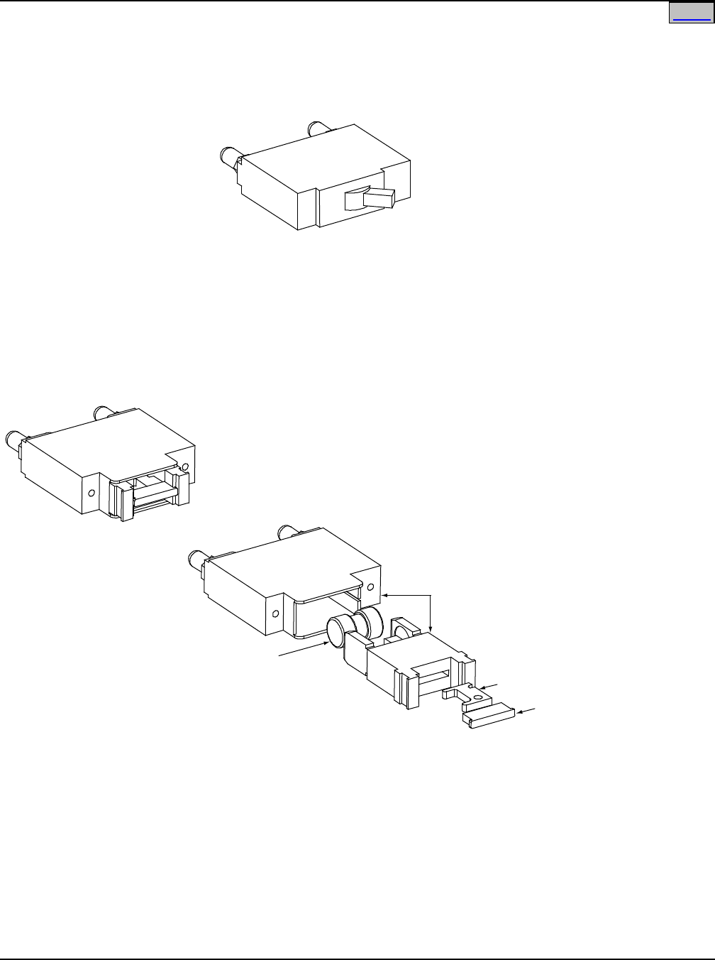
SAG582120600 System Application Guide
Issue BF, February 21, 2014 Spec. No. 582120600 (Model 801DB NVGB)
Page 36 of 72
This document is property of Emerson Network Power, Energy Systems, North America, Inc. and contains confidential and proprietary information owned by Emerson Network Power, Energy
Systems, North America, Inc. Any copying, use, or disclosure of it without the written permission of Emerson Network Power, Energy Systems, North America, Inc. is strictly prohibited.
Toggle-Handle Bullet Nose Circuit Breaker
BulletNose
Fuseholder, P/N 117201
(includes Fuseholder, Alarm Fuse,
and Alarm FuseSafety Cover
)
Alarm Fuse
Replacement
P/N 248610301
Safety Fuse Cover
Replacement
P/N 248898700
TPS/TLS
Fuse
Bullet Nose Fuseholder
BulletNose-Type Distribution DevicesforLists115and
125
Home

System Application Guide SAG582120600
Spec. No. 582120600 (Model 801DB NVGB) Issue BF, February 21, 2014
Page 37 of 72
This document is property of Emerson Network Power, Energy Systems, North America, Inc. and contains confidential and proprietary information owned by Emerson Network Power, Energy
Systems, North America, Inc. Any copying, use, or disclosure of it without the written permission of Emerson Network Power, Energy Systems, North America, Inc. is strictly prohibited.
Toggle-Handle Bullet Nose Type Circuit Breakers
for Use in Lists 115 and 125
Ampere
Rating
Number of Poles
(and mounting
positions
required)
P/N
Lugs
Electrical
Trip1
(White
Handle)
Electrical/
Mechanical
Trip2
(Black Handle)
1
1
102272
101596
Up to 2 AWG lead sizes, use
lugs in Table 7 (1/4” clearance
holes on 5/8” centers.
From 1/0 to 350 kcmil lead
sizes, use lugs in Table 7
(Special Crimp Lug).
3
1
102273
101597
5
1
102274
101598
10
1
102275
101599
15
1
102276
101600
20
1
102277
101601
25
1
102278
101602
30
1
102279
101603
35
1
102280
101604
40
1
102281
101605
45
1
121998
121997
50
1
102282
101606
60
1
102283
101607
70
1
102284
101608
75
1
102285
101609
80
1
121996
121995
90
1
138887
138888
100 1 102286 101610
125 2 516991 516838
Use lugs in Table 7
(Special Crimp Lug).
150
(see Caution below)
2 516993 516839
175
(see
Caution
below) 2 144883 144884
200
(see Caution below) 2 121831 121832
225
(see
Caution
below) 3 144885 144886 Use lugs in Table 7 (Special
Crimp Lug) plus special lug
adapter P/N 545346 or lug
adapters listed in Table 7.
250
(see Caution below)
3 121835 121836
See Table 8 for recommended load distribution wire sizes.
Circuit Breaker Alarm Operation:
1 Provides an alarm during an electrical trip condition only.
2 Provides an alarm during an electrical or manual trip condition.
Caution: An overcurrent protective device with a rating of 150 amperes or greater SHALL HAVE an
empty mounting position between it and any other overcurrent protective device.
Table 5
Toggle-Handle Bullet Nose Type Circuit Breakers
for Use in Lists 115 and 125

SAG582120600 System Application Guide
Issue BF, February 21, 2014 Spec. No. 582120600 (Model 801DB NVGB)
Page 38 of 72
This document is property of Emerson Network Power, Energy Systems, North America, Inc. and contains confidential and proprietary information owned by Emerson Network Power, Energy
Systems, North America, Inc. Any copying, use, or disclosure of it without the written permission of Emerson Network Power, Energy Systems, North America, Inc. is strictly prohibited.
Bullet Nose-Type Fuseblocks and TLS/TPS Fuses
for Use in Lists 115 and 125
Ampere
Rating P/N Bussmann
P/N
Littelfuse
P/N Lugs
3
248230900
TPS-3
TLS003
Up to 2 AWG lead sizes, use
lugs in Table 7 (1/4” clearance
holes on 5/8” centers.
From 1/0 to 350 kcmil lead
sizes, use lugs in Table 7
(Special Crimp Lug).
5
248231000
TPS-5
TLS005
6
248231200
TPS-6
TLS006
10
248231500
TPS-10
TLS010
15
248231800
TPS-15
TLS015
20
248232100
TPS-20
TLS020
25
248232400
TPS-25
TLS025
30
248232700
TPS-30
TLS030
40
248233300
TPS-40
TLS040
50
248233900
TPS-50
TLS050
60
248234200
TPS-60
TLS060
70
248234500
TPS-70
TLS070
80
118413
--
TLS080
90
118414
--
TLS090
100
118415
--
TLS100
125
139052
--
TLS125
For each fuse ordered, also order a Bullet Nose Fuseblock P/N 117201.
Fuseblock P/N 117201 also includes...
(1) P/N 248610301 alarm fuse (GMT-18/100A), and
(1) P/N 248898700 safety fuse cover (GMT-X).
See Table 8 for recommended load distribution wire sizes.
Table 6
Bullet Nose-Type Fuseblocks and TLS/TPS Fuses
for Use in Lists 115 and 125
Home

System Application Guide SAG582120600
Spec. No. 582120600 (Model 801DB NVGB) Issue BF, February 21, 2014
Page 39 of 72
This document is property of Emerson Network Power, Energy Systems, North America, Inc. and contains confidential and proprietary information owned by Emerson Network Power, Energy
Systems, North America, Inc. Any copying, use, or disclosure of it without the written permission of Emerson Network Power, Energy Systems, North America, Inc. is strictly prohibited.
Lugs for Use with Lists 115 and 125 Distribution Panels
(two hole, 1/4” bolt clearance hole on 5/8” centers)
Lead Size (AWG) P/N
8 245390200
6 245346700
4 245346800
2 245346900
1/0 245393500 (special lug)
2/0 245393600 (special lug)
3/0 245393700 (special lug)
4/0 245393800 (special lug)
250 kcmil 514872 (special lug)
350 kcmil 514873 (special lug)
3-Pole Device Special Adapter 545346
Lugs for Use with P/Ns 547991, 556377, and 556378 Lug Adapter Kits
(two hole, 3/8” bolt clearance holes on 1” centers)
Wire Size
Part Number
6 AWG 245349900
4 AWG 245350000
2 AWG 245348200
1/0 AWG 245347100
2/0 AWG 245347200
3/0 AWG 245347300
4/0 AWG 245347400
250 kcmil 245347500
300 kcmil 245347600
350 kcmil 245347700
400 kcmil 245347800
500 kcmil 245347900
600 kcmil 245348000
750 kcmil 245348100
For one-pole circuit breaker, cables larger than 2 AWG require an H-TAP connection.
For two-pole circuit breaker, use special lugs per table.
For three-pole circuit breaker and 3-pole ground/return, use either special lugs per
table with adapter P/N 545346, or adapter kit P/N 547991, 556377, or 556378 with
2-hole lugs having 3/8” clearance holes on 1” centers.
For fuseblock (P/N 117201), cables larger than 2 AWG require H-tap. Special lugs
listed above can be used but will use two positions of the distribution panel.
Table 7
Lugs for Use with Lists 115 and 125 Distribution Panels
Home
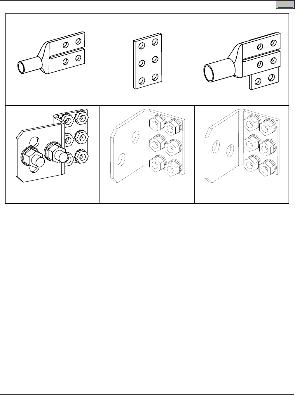
SAG582120600 System Application Guide
Issue BF, February 21, 2014 Spec. No. 582120600 (Model 801DB NVGB)
Page 40 of 72
This document is property of Emerson Network Power, Energy Systems, North America, Inc. and contains confidential and proprietary information owned by Emerson Network Power, Energy
Systems, North America, Inc. Any copying, use, or disclosure of it without the written permission of Emerson Network Power, Energy Systems, North America, Inc. is strictly prohibited.
Special Lugs and Adapters Referenced in Table 7
Special Lug
(See Table 7 for
Part Numbers)
Special Adapter P/N 545346
Special Lug and Adapter
3-Pole Lug Adapter Kit, P/N
547991
Right Angle
Lug Adapter Kit, P/N 556377
Right Angle
Lug Adapter Kit, P/N 556378
Home
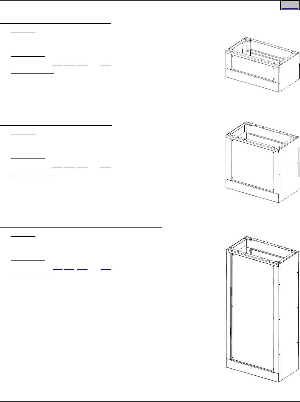
System Application Guide SAG582120600
Spec. No. 582120600 (Model 801DB NVGB) Issue BF, February 21, 2014
Page 41 of 72
This document is property of Emerson Network Power, Energy Systems, North America, Inc. and contains confidential and proprietary information owned by Emerson Network Power, Energy
Systems, North America, Inc. Any copying, use, or disclosure of it without the written permission of Emerson Network Power, Energy Systems, North America, Inc. is strictly prohibited.
Box Framework Extensions
One (1) Foot Box Framework Extension
Features
♦ The 1 Foot Box Framework Extension allows a standard 7 foot box
framework to extend to 8 feet.
Restrictions
For use in Lists 105 106, 107 and 108.
Ordering Notes
1) Order as required, P/N 544201.
Two (2) Foot Box Framework Extension
Features
♦ The 2 Foot Box Framework Extension allows a standard 7 foot box
framework to extend to 9 feet.
Restrictions
For use in Lists 105 106, 107 and 108.
Ordering Notes
1) Order as required, P/N 544202.
Four and One-Half (4-1/2) Foot Box Framework Extension
Features
♦ The 4-1/2 Foot Box Framework Extension allows a standard 7 foot box
framework to extend to 11-1/2 feet.
Restrictions
For use in Lists 105 106, 107 and 108.
Ordering Notes
1) Order as required, P/N 544203.
Home

SAG582120600 System Application Guide
Issue BF, February 21, 2014 Spec. No. 582120600 (Model 801DB NVGB)
Page 42 of 72
This document is property of Emerson Network Power, Energy Systems, North America, Inc. and contains confidential and proprietary information owned by Emerson Network Power, Energy
Systems, North America, Inc. Any copying, use, or disclosure of it without the written permission of Emerson Network Power, Energy Systems, North America, Inc. is strictly prohibited.
Wiring Notes
Refer also to the next section, Wiring Illustrations.
Bay Frame Grounding Wire Sizes and Lugs Selection
Features
♦ 1/4” clearance holes on 5/8" centers are provided for installation of customer provided two-hole lugs.
Restrictions
All lugs for customer connections must be ordered separately.
Customer needs to supply lug mounting bolts and hardware.
Ordering Notes
1) The recommended frame grounding wire size is 6 AWG. The recommended lug is P/N 245346700.
External Alarm Wiring—List 105 and 107 Bays
Features
♦ An external alarm circuit card is located behind the top left panel in each bay. This circuit card provides
three sets of Form C relay contacts for external alarms. Terminal blocks are provided on the circuit card
for customer external alarm connections and RS485 connections.
Restrictions
Relay contacts are rated for 1 amp at 60 VDC.
Terminal block wire size capacity is 14 to 26 AWG.
Ordering Notes
1) Recommended Wire Size: 22 AWG for Loop Lengths Up to 200 ft.
18-20 AWG for Loop Lengths Over 200 ft.
External Alarm and Control Wiring—List 106 and 108 Bays
Input/Output Circuit Card Features
♦ An input/output circuit card is located behind the top left panel in each bay. This circuit card provides four
alarm relays, each with one set of Form C relay contacts, for external alarms. Terminal blocks are
provided on the circuit card for customer external alarm connections.
Restrictions
Relay contacts are rated for 0.6 amp at 60 VDC.
Terminal block wire size capacity is 14 AWG max.
Ordering Notes
1) Recommended Wire Size: 22 AWG for Loop Lengths Up to 200 ft.
18-20 AWG for Loop Lengths Over 200 ft.
Auxiliary Fuse Circuit Card Features
♦ An auxiliary fuse circuit card is located behind the top right panel in each bay. This circuit card provides
four fuses for auxiliary equipment loads and two fuses for optional external (ABS) power to the
Meter/Alarm Panel. All fuses are rated at 1-1/3A. Terminal blocks are provided on the circuit card for
auxiliary load connections, external (ABS) meter input power connections, and optional external sense
lead connections.
Restrictions
Terminal block wire size capacity is 14 AWG max.
Installer must make system ground/return connection(s) to side A and side B Ground/Return Input busbars
located behind circuit card.
Home

System Application Guide SAG582120600
Spec. No. 582120600 (Model 801DB NVGB) Issue BF, February 21, 2014
Page 43 of 72
This document is property of Emerson Network Power, Energy Systems, North America, Inc. and contains confidential and proprietary information owned by Emerson Network Power, Energy
Systems, North America, Inc. Any copying, use, or disclosure of it without the written permission of Emerson Network Power, Energy Systems, North America, Inc. is strictly prohibited.
Ordering Notes
1) Recommended Wire Size (Auxiliary Fuse load and return): 14 AWG
2) Recommended Wire Size (Ground/Return Input busbars): 14 AWG
Load Distribution Wire Sizes Selection
Features
♦ Load distribution (load side) leads terminated in the appropriate lug are connected to the ‘load side’
terminations provided on each Distribution Panel. See Load Distribution Connections under Wiring
Illustrations in ACCESSORY DESCRIPTIONS.
♦ Load distribution (return side) leads terminated in the appropriate lug are connected to the ‘load return
side’ terminations provided on the optional internal ground/return bars or to external ground/return bars.
See Load Distribution Connections under Wiring Illustrations in ACCESSORY DESCRIPTIONS.
Restrictions
The rating of the distribution device determines the wire size requirements. Refer to the American National
Standards Institute (ANSI) approved National Fire Protection Association's (NFPA) National Electrical Code
(NEC) and applicable local codes.
All lugs for customer connections must be ordered separately.
Customer needs to supply lug mounting bolts and hardware.
Maximum size of wire to be connected to a single lug position and maximum lug width are listed under
Distribution Devices and Lug Selection in ACCESSORY DESCRIPTIONS.
Ordering Notes
1) The type of distribution device determines the load lug hole size and spacing requirements. The rating of
the distribution device determines the wire size requirements. For wire size and lug selection; refer to
Distribution Devices and Lug Selection in ACCESSORY DESCRIPTIONS and Table 8 and Table 9.
Home

SAG582120600 System Application Guide
Issue BF, February 21, 2014 Spec. No. 582120600 (Model 801DB NVGB)
Page 44 of 72
This document is property of Emerson Network Power, Energy Systems, North America, Inc. and contains confidential and proprietary information owned by Emerson Network Power, Energy
Systems, North America, Inc. Any copying, use, or disclosure of it without the written permission of Emerson Network Power, Energy Systems, North America, Inc. is strictly prohibited.
Fuse/Circuit
Breaker
Amperage
Recm 90
°
C Wire Size (1)
14 AWG 12 AWG 10 AWG 8 AWG 6 AWG 4 AWG 2 AWG
Loop Length (feet) (2)
1, 3, 5,
6, 10A 37 (3, 4) 58 (3, 4) 93 (3, 4) -- -- -- --
15A 24 (3, 4) 39 (3, 4) 62 (3, 4) -- -- -- --
20A -- 29 (3, 4) 46 (3, 4) 74 (3, 4) -- -- --
25A -- -- 37 (3, 4) 59 (3, 4) 94 (3, 4) -- --
30A -- -- 31 (3, 4) 49 (3, 4) 78 (3, 4) -- --
35A -- -- -- 42 (3, 4) 67 (3, 4) 107 (3, 4) --
40A -- -- -- 37 (3, 4) 59 (3, 4) 94 (3, 4) --
45A -- -- -- 33 (3, 4) 52 (3, 4) 83 (3, 4) --
50A -- -- -- 29 (3, 4) 47 (3, 4) 75 (3, 4) --
60A -- -- -- -- 39 (3, 4) 62 (3, 4) 99 (3, 4)
70A -- -- -- -- 33 (3) 53 (3, 4) 85 (3, 4)
75A -- -- -- -- 31 (3) 50 (3, 4) 79 (3, 4)
80A -- -- -- -- -- 47 (3, 4) 74 (3, 4)
90A -- -- -- -- -- 41 (3) 66 (3, 4)
100A -- -- -- -- -- -- 59 (3, 4)
1 Wire sizes based on recommendations of the American National Standards Institute (ANSI) approved
National Fire Protection Association's (NFPA) National Electrical Code (NEC). Table 310-16 for copper
wire at 90°C conductor temperature operating in ambients of 30
°
C and 40
°
C was used. For other operating
ambient temperatures, refer to the NEC. For operation in countries where the NEC is not recognized,
follow applicable codes.
2 Recommended wire sizes are sufficient to restrict voltage drop to 1.0 volt or less at listed branch current for
the loop lengths shown. Loop length is the sum of the lengths of the positive and negative leads.
3 Wire Size / Loop Length Combination Calculated using 30°C Ambient Operating Temperature.
4 Wire Size / Loop Length Combination Calculated using 40°C Ambient Operating Temperature.
Table 8
(cont'd on next page)
Recommended Load Distribution Wire Sizes for
TLS/TPS Fuse and Bullet Nose-Type Circuit Breaker
Home

System Application Guide SAG582120600
Spec. No. 582120600 (Model 801DB NVGB) Issue BF, February 21, 2014
Page 45 of 72
This document is property of Emerson Network Power, Energy Systems, North America, Inc. and contains confidential and proprietary information owned by Emerson Network Power, Energy
Systems, North America, Inc. Any copying, use, or disclosure of it without the written permission of Emerson Network Power, Energy Systems, North America, Inc. is strictly prohibited.
Fuse/
Circuit
Breaker
Amperage
Recm 90
°
C Wire Size (1)
4 AWG 2 AWG 1/0 AWG 2/0 AWG 3/0 AWG 4/0 AWG 250
kcmil
350
kcmil
Loop Length (feet) (2)
90A 41
(3)
66
(3, 4)
105
(3, 4)
133
(4)
-- -- -- --
100A -- 59
(3, 4)
95
(3, 4)
119
(3, 4)
-- -- -- --
125A -- 47
(3)
76
(3, 4)
95
(3, 4)
120
(4)
-- -- --
150A -- -- 63
(3, 4)
79
(3, 4)
100
(3, 4)
-- -- --
175A -- -- -- 68
(3, 4)
86
(3, 4)
108
(3, 4)
-- --
200A -- -- -- -- 75
(3, 4)
95
(3, 4)
112
(3, 4)
--
225A -- -- -- -- 67
(3)
84
(3, 4)
100
(3, 4)
--
250A -- -- -- -- -- 76
(3, 4,
7)
90
(3, 4,
7)
126
(3, 4,
7)
1 Wire sizes based on recommendations of the American National Standards Institute (ANSI) approved
National Fire Protection Association's (NFPA) National Electrical Code (NEC). Table 310-16 for copper
wire at 90°C conductor temperature operating in ambients of 30
°
C and 40
°
C was used. For other operating
ambient temperatures, refer to the NEC. For operation in countries where the NEC is not recognized,
follow applicable codes.
2 Recommended wire sizes are sufficient to restrict voltage drop to 1.0 volt or less at listed branch current for
the loop lengths shown. Loop length is the sum of the lengths of the positive and negative leads.
3 Wire Size / Loop Length Combination Calculated using 30°C Ambient Operating Temperature.
4 Wire Size / Loop Length Combination Calculated using 40°C Ambient Operating Temperature.
Table 8
(cont'd from previous page)
Recommended Load Distribution Wire Sizes for
TLS/TPS Fuse and Bullet Nose-Type Circuit Breaker
Home

SAG582120600 System Application Guide
Issue BF, February 21, 2014 Spec. No. 582120600 (Model 801DB NVGB)
Page 46 of 72
This document is property of Emerson Network Power, Energy Systems, North America, Inc. and contains confidential and proprietary information owned by Emerson Network Power, Energy
Systems, North America, Inc. Any copying, use, or disclosure of it without the written permission of Emerson Network Power, Energy Systems, North America, Inc. is strictly prohibited.
Fuse/
Circuit
Breaker
Amperage
Recm 90
°
C Wire Size (1)
6
AWG
4
AWG
2
AWG
1/0
AWG
2/0
AWG
3/0
AWG
4/0
AWG
250
kcmil
300
kcmil
350
kcmil
Loop Length (feet) (2)
70A 33
(3)
53
(3, 4)
85
(3, 4)
135
(3, 4)
-- -- -- -- -- --
80A -- 47
(3, 4)
74
(3, 4)
118
(3, 4)
-- -- -- -- -- --
100A -- -- 59
(3, 4)
95
(3, 4)
119
(3, 4)
-- -- -- -- --
150A -- -- -- 63
(3, 4)
79
(3, 4)
100
(3, 4)
-- -- -- --
200A -- -- -- -- -- 75
(3, 4)
95
(3, 4)
112
(3, 4)
-- --
225A -- -- -- -- -- 67
(3)
84
(3, 4)
100
(3, 4)
120
(3, 4)
--
250A -- -- -- -- -- -- 76
(3)
90
(3, 4)
108
(3, 4)
126
(3, 4)
1 Wire sizes based on recommendations of the American National Standards Institute (ANSI) approved
National Fire Protection Association's (NFPA) National Electrical Code (NEC). Table 310-16 for copper
wire at 90°C conductor temperature operating in ambients of 30
°
C and 40
°
C was used. For other operating
ambient temperatures, refer to the National Electrical Code. For operation in countries where the NEC is
not recognized, follow applicable codes.
2 Recommended wire sizes are sufficient to restrict voltage drop to 1.0 volt or less at listed branch current for
the loop lengths shown. Loop length is the sum of the lengths of the positive and negative leads.
3 Wire Size / Loop Length Combination Calculated using 30°C Ambient Operating Temperature.
4 Wire Size / Loop Length Combination Calculated using 40°C Ambient Operating Temperature.
5 Single-hole lug, 5/16" bolt clearance hole. Refer to drawing 031110100 for lug crimping information.
Table 9
Recommended Load Distribution Wire Sizes for TPL Fuse
Home

System Application Guide SAG582120600
Spec. No. 582120600 (Model 801DB NVGB) Issue BF, February 21, 2014
Page 47 of 72
This document is property of Emerson Network Power, Energy Systems, North America, Inc. and contains confidential and proprietary information owned by Emerson Network Power, Energy
Systems, North America, Inc. Any copying, use, or disclosure of it without the written permission of Emerson Network Power, Energy Systems, North America, Inc. is strictly prohibited.
DC Input Cable Sizes and Lugs Selection
Features
♦ DC input (-48V) leads terminated in the appropriate lug are connected to the List 145 Bay Input Feed and
Shunt Assembly. See DC Input Connections under Wiring Illustrations in ACCESSORY
DESCRIPTIONS.
♦ DC input return leads terminated in the appropriate lug are connected to the optional internal
ground/return bars or to external ground/return bars. See DC Input Connections under Wiring
Illustrations in ACCESSORY DESCRIPTIONS.
Restrictions
All lugs for customer connections must be ordered separately.
Customer needs to supply lug mounting bolts and hardware.
Maximum size of wire to be connected to a single lug position and maximum lug width are as shown in the
Wiring Illustrations.
Ordering Notes
1) DC input cable size varies depending on power requirements, therefore no specific information is
provided for cable size. Refer to Table 10 for recommended cable sizes and lugs at rated maximum bay
load (640A per Distribution Panel, 1800A per Side 6-Panel Bay, 2400A per Side 8-Panel Bay). Note that
loads typically should not exceed 80% of capacity; therefore, input cables have been sized for an
overcurrent protection device rated at 800A. When making connections, observe correct polarity.
2) For other available lugs, refer to drawings 031110100 through 031110300.
External
Overcurrent
Protection
Device Rating
Ambient
Operating
Temperature (1)
Loop
Length (Ft)
1.0 Voltage
Drop (2)
Loop
Length (Ft)
0.25 Voltage
Drop (2)
Recm 90
°
C
Wire Size
(AWG) (1)
Recommended
Crimp Lug (3)
800A 40°C 84.5 21.1 750 kcmil 245348100
168.9
42.2
(2) 750 kcmil
1 Wire sizes are based on recommendations of the American National Standards Institute (ANSI)
approved National Fire Protection Association's (NFPA) National Electrical Code (NEC). Table
310-17 for copper wire rated at 90
°
C conductor temperature operating in ambient temperature of
40
°
C was used. For other operating ambient temperatures, refer to the NEC. For operation in
countries where the NEC is not recognized, follow applicable codes.
2 Recommended wire sizes are sufficient to restrict voltage drop to the voltage shown in the column
heading, or less, at rated full load output current of the system for the loop lengths shown in this
column. Loop length is the sum of the lengths of the positive and negative leads.
3 Two-hole lug, 3/8 bolt clearance hole, 1.00" centers. Refer to drawing 031110100 for lug crimping
information.
Table 10
Recommended DC Input
Wire Size and Lug Selection
Home
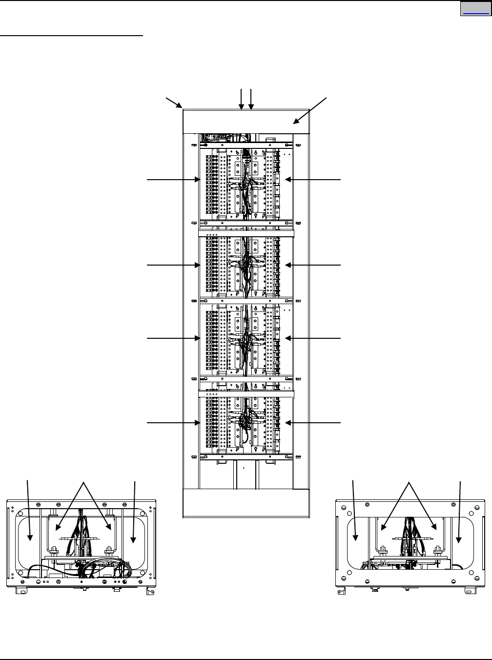
SAG582120600 System Application Guide
Issue BF, February 21, 2014 Spec. No. 582120600 (Model 801DB NVGB)
Page 48 of 72
This document is property of Emerson Network Power, Energy Systems, North America, Inc. and contains confidential and proprietary information owned by Emerson Network Power, Energy
Systems, North America, Inc. Any copying, use, or disclosure of it without the written permission of Emerson Network Power, Energy Systems, North America, Inc. is strictly prohibited.
Wiring Illustrations
Overall Installer’s Connections
DC Input Connections
Top Feed
(Bottom Feed Similar)
(See Detail D)
Rear View
8-Panel Bay
(6-Panel Bay Similar)
Load
Distribution
Connections
(See Detail C)
Load
Distribution
Connections
(See Detail C)
Load
Distribution
Connections
(See Detail C)
Load
Distribution
Connections
(See Detail C)
Load
Distribution
Connections
(See Detail C)
Load
Distribution
Connections
(See Detail C)
Load
Distribution
Connections
(See Detail C)
Load
Distribution
Connections
(See Detail C)
Bay Frame
Grounding
Connection
(See Detail A)
External Alarm and
Meter/Alarm Card Input
Connections
(See Detail B)
Top View
Top Feed Installations
Bottom View
Bottom Feed Installations
Load
Cables
Input
Cables
Load
Cables
Load
Cables
Input
Cables
Load
Cables
Bay Overall
Connections
Diagram
Home
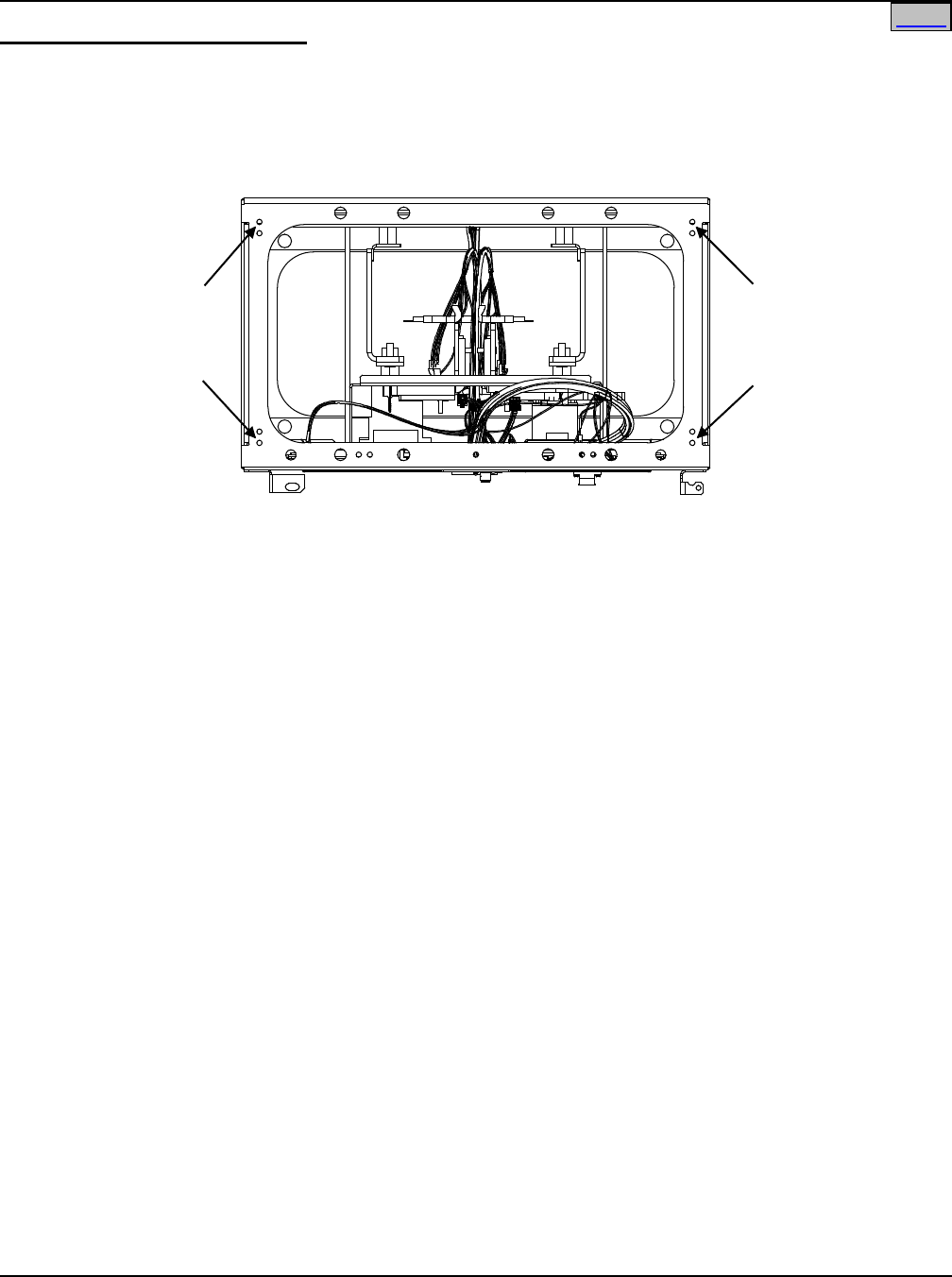
System Application Guide SAG582120600
Spec. No. 582120600 (Model 801DB NVGB) Issue BF, February 21, 2014
Page 49 of 72
This document is property of Emerson Network Power, Energy Systems, North America, Inc. and contains confidential and proprietary information owned by Emerson Network Power, Energy
Systems, North America, Inc. Any copying, use, or disclosure of it without the written permission of Emerson Network Power, Energy Systems, North America, Inc. is strictly prohibited.
Bay Frame Grounding Connection
Detail A
Top View
1/4" clearance holes
on 5/8" centers are
provided for installation
of customer provided
two-hole lug.
1/4" clearance holes
on 5/8" centers are
provided for installation
of customer provided
two-hole lug.
Bay Frame Grounding Connection
Home
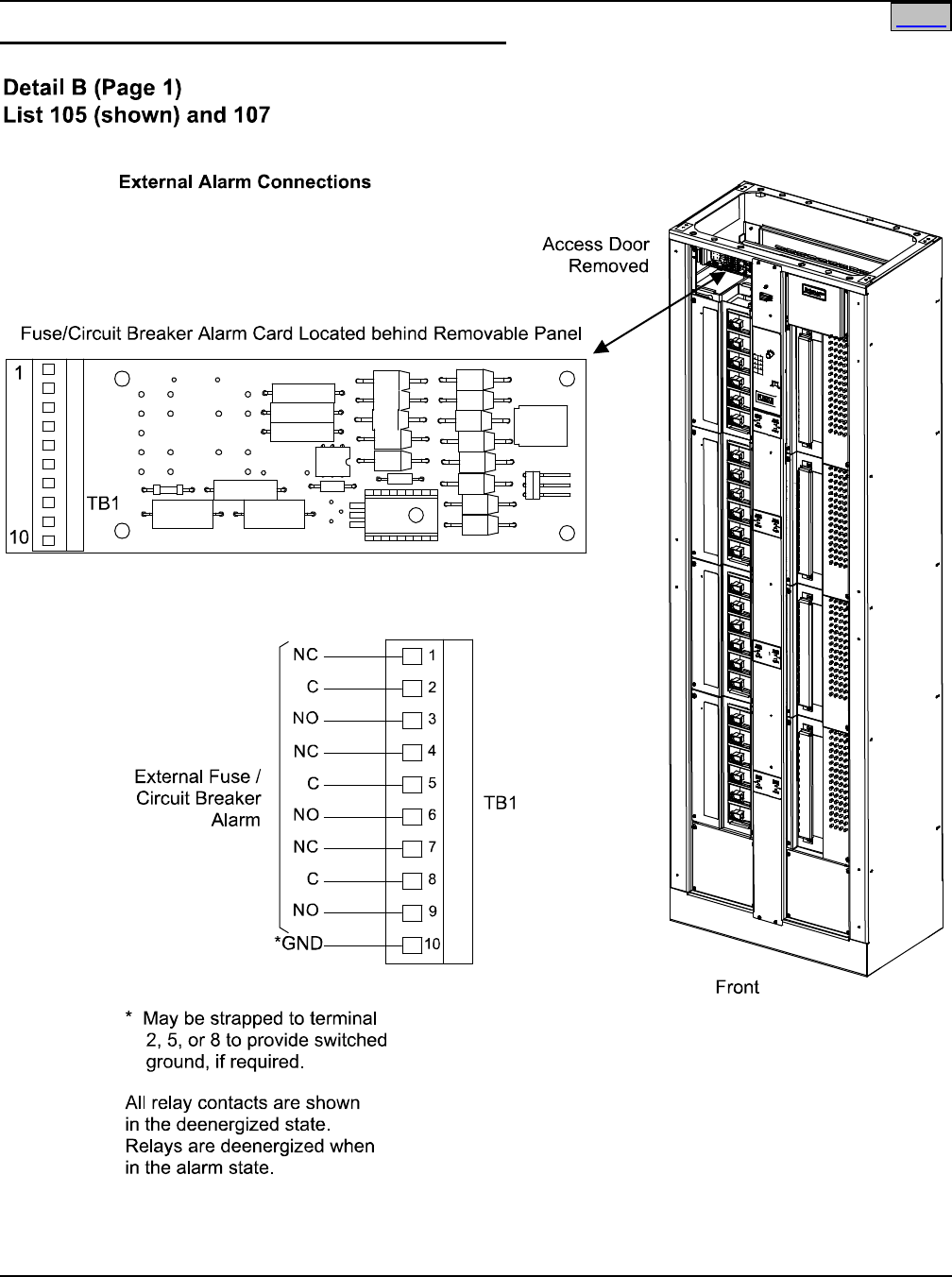
SAG582120600 System Application Guide
Issue BF, February 21, 2014 Spec. No. 582120600 (Model 801DB NVGB)
Page 50 of 72
This document is property of Emerson Network Power, Energy Systems, North America, Inc. and contains confidential and proprietary information owned by Emerson Network Power, Energy
Systems, North America, Inc. Any copying, use, or disclosure of it without the written permission of Emerson Network Power, Energy Systems, North America, Inc. is strictly prohibited.
External Alarm and Meter/Alarm Card Input Connections
Home
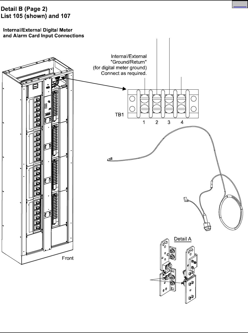
System Application Guide SAG582120600
Spec. No. 582120600 (Model 801DB NVGB) Issue BF, February 21, 2014
Page 51 of 72
This document is property of Emerson Network Power, Energy Systems, North America, Inc. and contains confidential and proprietary information owned by Emerson Network Power, Energy
Systems, North America, Inc. Any copying, use, or disclosure of it without the written permission of Emerson Network Power, Energy Systems, North America, Inc. is strictly prohibited.
List 156 Internal Fuse Kit
(Connect end with spade lug to terminal
3 or 4 of TB1, connect end with faston
connector to lug factory-installed on an
Input Feed and Shunt Assembly
[-48V Source, see Detail A].)
(one or two kits as ordered)
Connect faston connector
end of Internal Fuse Kit
to one of these lugs.
Input Feed
and Shunt
Assembly
-48V Input - B Feed
(for digital meter and alarm
circuit card power input)
Connect to an external source
or to List 156 Internal Fuse Kit,
if Feed B required.
-48V Input - A Feed
(for digital meter and alarm
circuit card power input)
Connect to an external source
or to List 156 Internal Fuse Kit.
Internal/External
“Ground/Return”
(for digital meter and alarm
circuit card power return)
Connect as required.
Access Door
Removed
Home
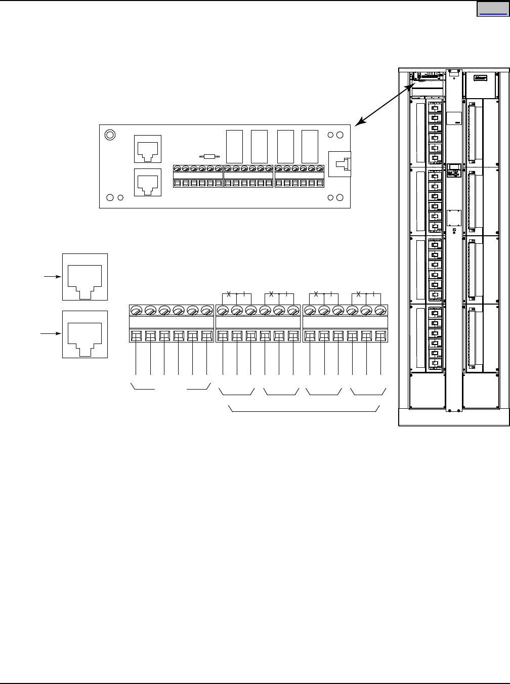
SAG582120600 System Application Guide
Issue BF, February 21, 2014 Spec. No. 582120600 (Model 801DB NVGB)
Page 52 of 72
This document is property of Emerson Network Power, Energy Systems, North America, Inc. and contains confidential and proprietary information owned by Emerson Network Power, Energy
Systems, North America, Inc. Any copying, use, or disclosure of it without the written permission of Emerson Network Power, Energy Systems, North America, Inc. is strictly prohibited.
TB9 TB7 TB8
NO CNC NO CNCNO CNCNO CNC
For
Future Use
J3
J2
Network
(Factory
Connection)
Ethernet
Port
Input/Output Card Located behind Removable Panel
1 6 1 6 1 6
NO=Normally Open. C=Common. NC=Normally Closed.
All alarm relays are shown in de-energized state. All relays
are de-energized for an alarm condition.
NOTE:
1.
Default Relay Mapping: K1 - Fuse Alarm
K2 - Low Voltage Alarm
K3 - Power Lost Alarm
K4 - Overcurrent 1 Alarm, Overcurrent 2 Alarm
2.
Default Alarm Settings: Low Voltage Alarm - 51.8 VDC
Power Lost - 42.0 VDC
Overcurrent 1 - 480 amps
Overcurrent 2 - 800 amps
3.
K1 K2 K3 K4
External Alarms
See Note 1, 2
Detail B (Page 3)
List 106 and 108 (shown)
Ethernet and External Alarm Connections
Home
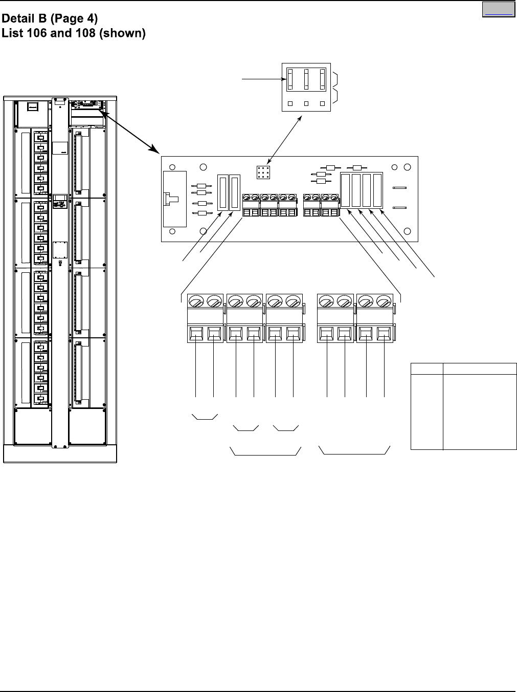
System Application Guide SAG582120600
Spec. No. 582120600 (Model 801DB NVGB) Issue BF, February 21, 2014
Page 53 of 72
This document is property of Emerson Network Power, Energy Systems, North America, Inc. and contains confidential and proprietary information owned by Emerson Network Power, Energy
Systems, North America, Inc. Any copying, use, or disclosure of it without the written permission of Emerson Network Power, Energy Systems, North America, Inc. is strictly prohibited.
For internal voltage sensing, set Sense Option jumper to Internal Sense position.
For system installation with external ground/return bar, connect Return (+) sense leads from ground
bars to TB5-1 (Return B) and TB5-2 (Return A), and set Sense Option jumper to Extenal Sense position.
For optional external (ABS) power to the Meter/Alarm assembly, connect source A to TB1
and source B to TB2. Observe correct polarity as shown.
Connect Return (+) leads for Fused Auxiliary Loads to system ground bar.
NOTES:
1.
2.
3.
F1 F2 F3 F4
F5
F6
Auxiliary Fuse Card
Located Behind
Removable Panel
External Sense
Internal Sense
Sense Option Jumper
(P/N 144134)
See Note 1
-48V
RTN
-48V
RTN
A B
1A (-48V)
2A (-48V)
3B (-48V)
4B (-48V)
Fused Aux.
Loads
See Note 3
ABS_A ABS_B
EXT
SNS
See
Note
1
TB5 TB1 TB2 TB3 TB4
See Note 2
2 1 2 1 2 1 2 1 2 1
Fuse Function
F1 Aux Load 1A
F2 Aux Load 2A
F3 Aux Load 3B
F4 Aux Load 4B
F5 ABS Power A
F6 ABS Power B
All fuses 1-1/3A.
External Sense, ABS and
Aux. Supply Connections
Home
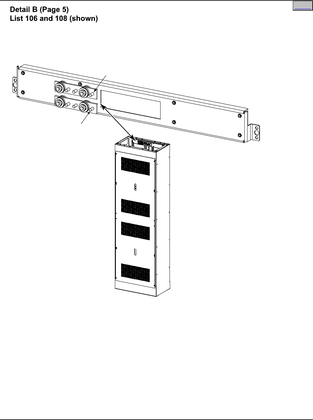
SAG582120600 System Application Guide
Issue BF, February 21, 2014 Spec. No. 582120600 (Model 801DB NVGB)
Page 54 of 72
This document is property of Emerson Network Power, Energy Systems, North America, Inc. and contains confidential and proprietary information owned by Emerson Network Power, Energy
Systems, North America, Inc. Any copying, use, or disclosure of it without the written permission of Emerson Network Power, Energy Systems, North America, Inc. is strictly prohibited.
Rear View
+RTN A
10-32 threaded stud.
See Note 1.
+RTN B
10-32 threaded stud.
See Note 2.
Ground/Return Input Connections for
Auxiliary Fuse Card
Connect “+RTN A” to the system Ground/Return busbar. If the bay is configured for A/B operation,
connect to the A side system Ground/Return busbar.
If the bay is configured for A/B operation, connect “+RTN B” to the B side system Ground/Return
busbar.
NOTES:
1.
2.
Home
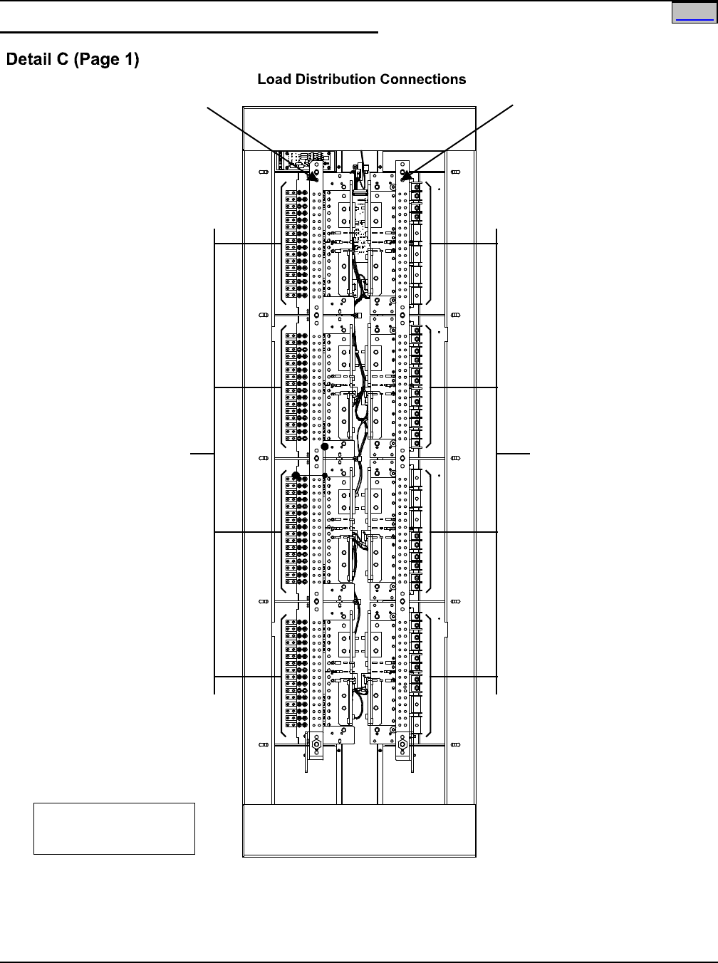
System Application Guide SAG582120600
Spec. No. 582120600 (Model 801DB NVGB) Issue BF, February 21, 2014
Page 55 of 72
This document is property of Emerson Network Power, Energy Systems, North America, Inc. and contains confidential and proprietary information owned by Emerson Network Power, Energy
Systems, North America, Inc. Any copying, use, or disclosure of it without the written permission of Emerson Network Power, Energy Systems, North America, Inc. is strictly prohibited.
Load Distribution Connections—Lists 105, 106, 107, 108
Portion of bay removed
in illustration for clarity.
SEE NEXT PAGE IF
TVSS DEVICE IS
INSTALLED IN BULLET
DEVICE MOUNTING
BLOCK
-48V Load Connections
Load Return Connections
to Optional Internal
Ground/Return Busbar
or Customer Provided
External Busbar.
-48V Load Connections
Load Return Connections
to Optional Internal
Ground/Return Busbar
or Customer Provided
External Busbar.
Optional Internal
Ground/ReturnBusbar
(Bay Length, shown)
or Optional Internal
Ground/Return Busbar
(Panel Length, see next pages)
or CustomerProvided
ExternalBusbar
Optional Internal
Ground/ReturnBusbar
(Bay Length, shown)
or Optional Internal
Ground/Return Busbar
(PanelLength, see next pages)
or Customer Provided
External Busbar
SEE NEXT PAGE IF
TVSS DEVICE IS
INSTALLED IN BULLET
DEVICE MOUNTING
BLOCK
Rear View
8-Panel Bay
(6-Panel Bay Similar)
Home
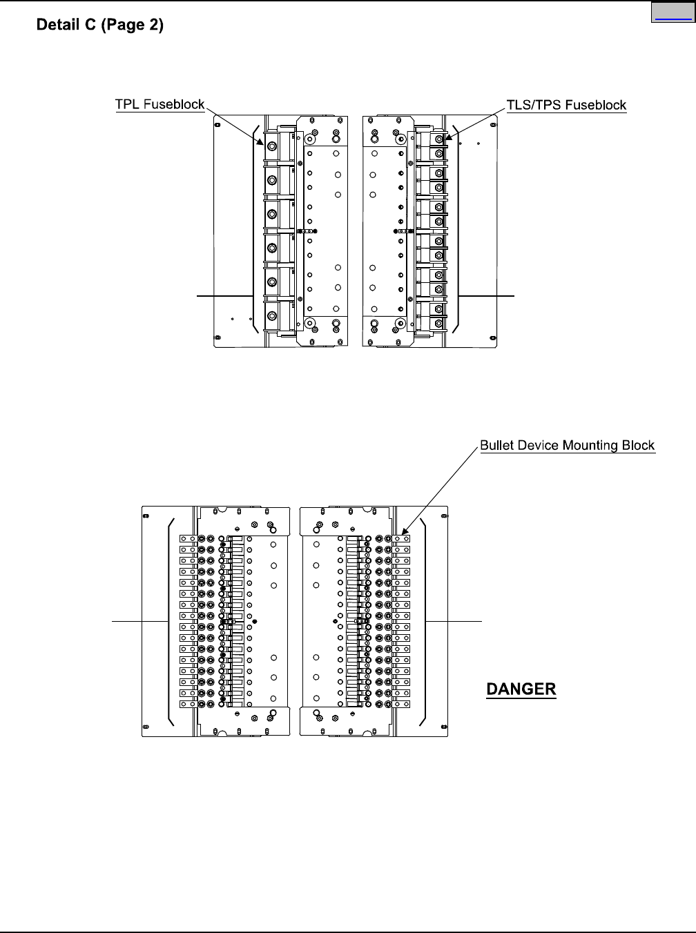
SAG582120600 System Application Guide
Issue BF, February 21, 2014 Spec. No. 582120600 (Model 801DB NVGB)
Page 56 of 72
This document is property of Emerson Network Power, Energy Systems, North America, Inc. and contains confidential and proprietary information owned by Emerson Network Power, Energy
Systems, North America, Inc. Any copying, use, or disclosure of it without the written permission of Emerson Network Power, Energy Systems, North America, Inc. is strictly prohibited.
5/16-18 swage studs
for installation of customer
provided single hole lugs.
(Torque to 132 in-lbs.)
(Maximum Lug Width is 1.800”.)
(Maximum Wire Size is 2/0 AWG.)
1/4-20 swage studs
for installation of customer
provided single hole lugs.
(Torque to 72 in-lbs.)
(Maximum Lug Width is 0.750”.)
(Maximum Wire Size is 2 AWG.)
-48V Load
Connections
-48V Load
Connections
Rear View
(wired from the rear of the bay)
1/4-20 studs on 5/8” centers for
installation of customer provided
two hole lugs.
(Torque to 72 in-lbs.)
(Maximum Lug Width is 0.610”.)
(Maximum Wire Size is 2 AWG.)
-48V Load
Connections*
or
TVSS
Connections
(+Ground)*
Ensure leads are connected to
proper polarity for the device
installed, either a Distribution
Device (load lead connection)
or a TVSS Device (ground
connection).
*
-48V Load
Connections*
or
TVSS
Connections
(+Ground)*
-48V Load Connections and
TVSS Device Ground Connections to
List 115 and 125 Distribution Panel
Rear View
(wired from the rear of the bay)
-48V Load Connections to
List 110 and 120 Distribution Panel
Home
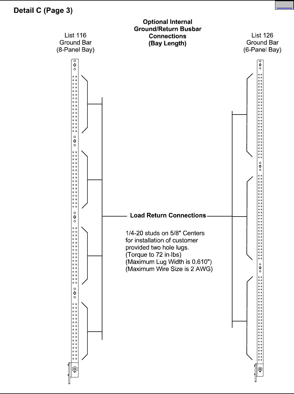
System Application Guide SAG582120600
Spec. No. 582120600 (Model 801DB NVGB) Issue BF, February 21, 2014
Page 57 of 72
This document is property of Emerson Network Power, Energy Systems, North America, Inc. and contains confidential and proprietary information owned by Emerson Network Power, Energy
Systems, North America, Inc. Any copying, use, or disclosure of it without the written permission of Emerson Network Power, Energy Systems, North America, Inc. is strictly prohibited.
Home
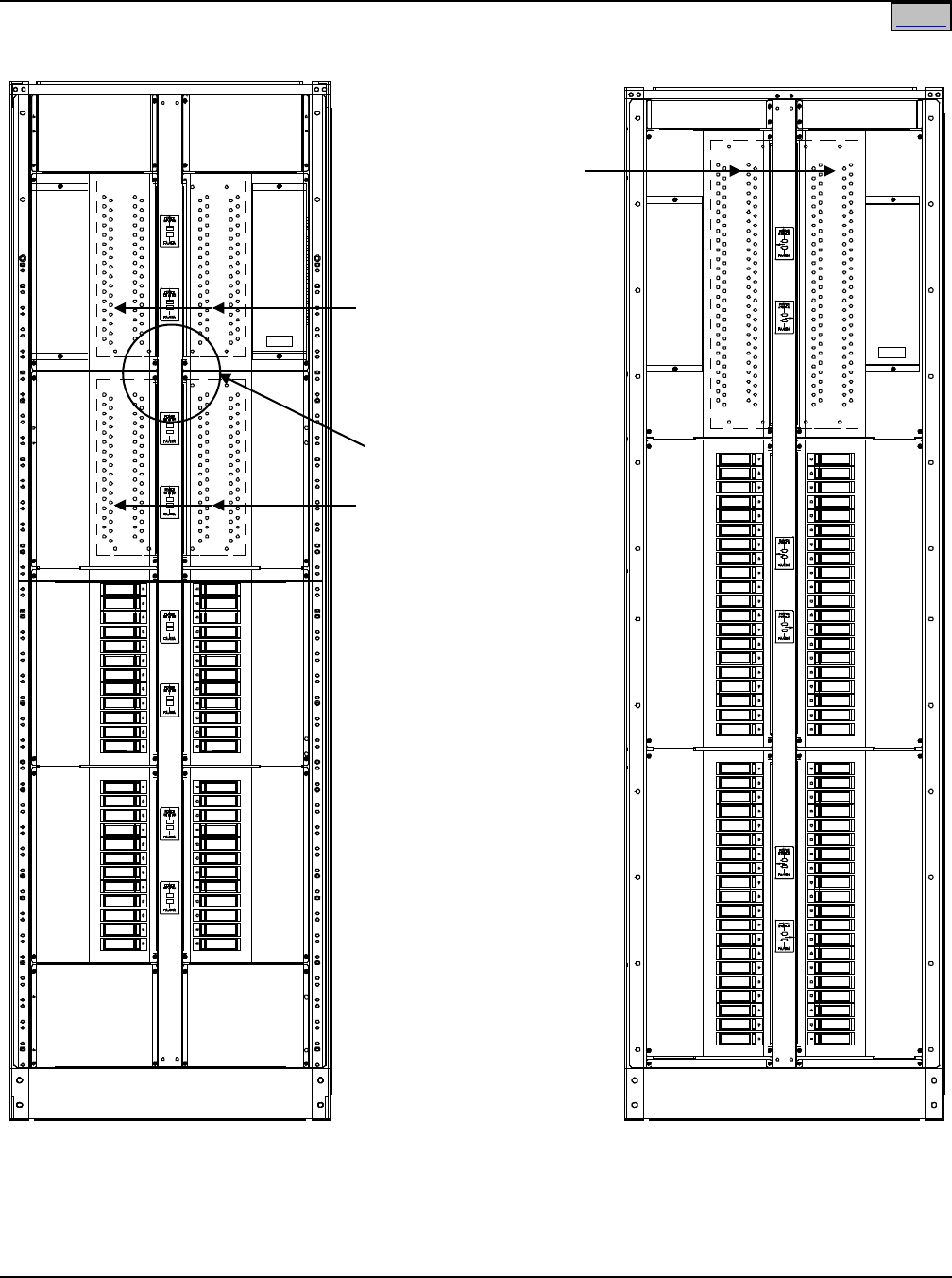
SAG582120600 System Application Guide
Issue BF, February 21, 2014 Spec. No. 582120600 (Model 801DB NVGB)
Page 58 of 72
This document is property of Emerson Network Power, Energy Systems, North America, Inc. and contains confidential and proprietary information owned by Emerson Network Power, Energy
Systems, North America, Inc. Any copying, use, or disclosure of it without the written permission of Emerson Network Power, Energy Systems, North America, Inc. is strictly prohibited.
Detail C (Page 4)
Top Feed Arrangement Shown
For Bottom Feed Arrangement,
Ground Bar Assemblies Are
Installed in Bottom Most
Mounting Positions
Front View
8-Panel Bay
Front View
6-Panel Bay
Optional List 127
Ground Bar Assembly
(Each List 127 provides
two [2] Ground Bar
Assemblies.)
Optional List 117
Ground Bar Assembly
(Each List 117 provides
two [2] Ground Bar
Assemblies.)
Optional List 117
Ground Bar Assembly
(Each List 117 provides
two [2] Ground Bar
Assemblies.)
List 139
Paralleling Bars
Optional Internal
Ground/Return Busbar
Connections
(Distribution Panel Length,
Replaces a Distribution Panel)
Home
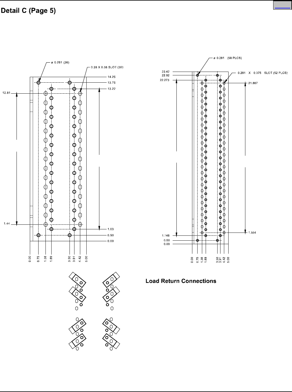
System Application Guide SAG582120600
Spec. No. 582120600 (Model 801DB NVGB) Issue BF, February 21, 2014
Page 59 of 72
This document is property of Emerson Network Power, Energy Systems, North America, Inc. and contains confidential and proprietary information owned by Emerson Network Power, Energy
Systems, North America, Inc. Any copying, use, or disclosure of it without the written permission of Emerson Network Power, Energy Systems, North America, Inc. is strictly prohibited.
Optional Internal
Ground/Return Busbar
Connections
(Distribution Panel Length,
Replaces a Distribution Panel)
List 117
Ground Bar
(8-Panel Bay)
List 127
Ground Bar
(6-Panel Bay)
1/4” clearance holes/slots on 5/8” centers
for installation of customer
provided two hole lugs.
(Torque to 72 in-lbs.)
(Maximum Lug Width is 0.610”.)
(Maximum Wire Size is 2 AWG.)
Typical Lug Installation
0.625” Centers
Right
Side
Left
Side
Top
Feed
Bottom
Feed
14 SPACES ON
0.81 CENTERS
= 11.38
15 SPACES ON
0.81 CENTERS
= 12.19
26 SPACES ON
0.812 CENTERS
= 21.125 25 SPACES ON
0.812 CENTERS
= 20.313
Home
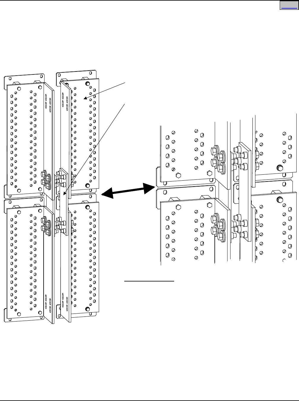
SAG582120600 System Application Guide
Issue BF, February 21, 2014 Spec. No. 582120600 (Model 801DB NVGB)
Page 60 of 72
This document is property of Emerson Network Power, Energy Systems, North America, Inc. and contains confidential and proprietary information owned by Emerson Network Power, Energy
Systems, North America, Inc. Any copying, use, or disclosure of it without the written permission of Emerson Network Power, Energy Systems, North America, Inc. is strictly prohibited.
Internal Ground Bar Assembly
(P/O List 117)
Paralleling Bar
(List 139)
Hardware Build-Up
3/8-16 x 1-1/4 Bolt
3/8 Belleville Lock Washer
3/8 Flat Washer
Internal Ground Bar Assembly
Paralleling Bar
TORQUE TO 180 IN-LBS
Detail C (Page 6)
Optional Internal
Ground/Return Busbar
Paralleling Bar
Home
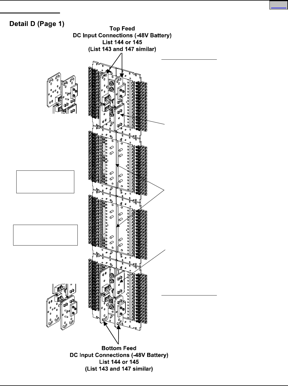
System Application Guide SAG582120600
Spec. No. 582120600 (Model 801DB NVGB) Issue BF, February 21, 2014
Page 61 of 72
This document is property of Emerson Network Power, Energy Systems, North America, Inc. and contains confidential and proprietary information owned by Emerson Network Power, Energy
Systems, North America, Inc. Any copying, use, or disclosure of it without the written permission of Emerson Network Power, Energy Systems, North America, Inc. is strictly prohibited.
DC Input Connections
3/8” clearance holes/slots on 1.00” centers
for installation of customer-
provided two hole lugs.
(Torque to 180 in-lbs)
(Maximum Lug Width is 2.00”)
(Maximum Wire Size is 750 kcmil)
Bottom Feed Installations
List 143, 144, 145 or 147
Input Feed and
Shunt Assembly
Addtional Input Feed and Shunt Assemblies
are installed on any Distribution Panel not
paralleled with a Distribution Panel that has
an Input Feed and Shunt Assembly installed.
List 143, 144, 145 or 147
Input Feed and
Shunt Assembly
3/8” clearance holes/slots on 1.00” centers
for installation of customer-
provided two hole lugs.
(Torque to 180 in-lbs)
(Maximum Lug Width is 2.00”)
(Maximum Wire Size is 750 kcmil)
Top Feed Installations
List 143 or 147
List 143 or 147
Rear View
8-Panel Bay
(6-Panel Bay Similar)
Portion of bay removed
in illustration for clarity.
Home
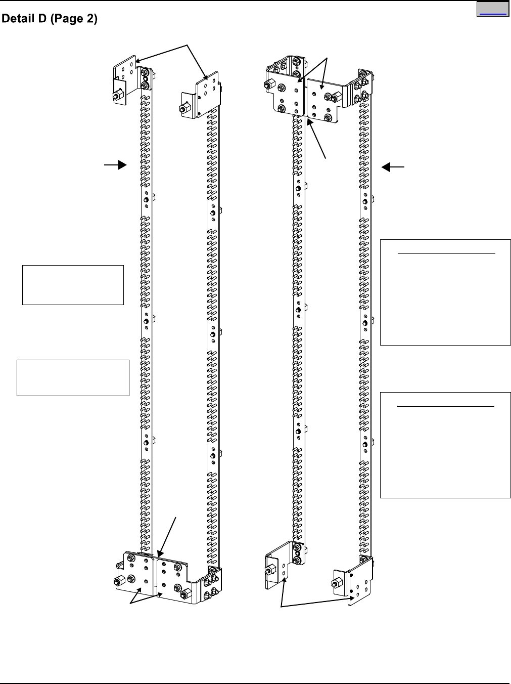
SAG582120600 System Application Guide
Issue BF, February 21, 2014 Spec. No. 582120600 (Model 801DB NVGB)
Page 62 of 72
This document is property of Emerson Network Power, Energy Systems, North America, Inc. and contains confidential and proprietary information owned by Emerson Network Power, Energy
Systems, North America, Inc. Any copying, use, or disclosure of it without the written permission of Emerson Network Power, Energy Systems, North America, Inc. is strictly prohibited.
Optional List 148 2400A Ground/Return
Input Kit providesAdditional DC Input
Connections (Battery ReturnLeads)
3/8” clearance holes on
1.00” centers for
installation of customer
provided two hole lugs.
(Torque to 180 in-lbs)
(Max. lug width is 2.00”)
(Max. wire size is 750 kcmil)
Top and BottomFeed
3/8” clearance holes on
1.00” centers for
installation of customer
provided two hole lugs.
(Torque to 180 in-lbs)
(Max. lug width is 2.00”)
(Max. wire size is 750 kcmil)
List 148 Feed
Optional
bonding
strap (P/O
List 148)
can be
removed
if not
required.
Optional
bonding
strap(P/O
List148)
can be
removed
ifnot
required.
Top Feed DC Input Connections
(Battery Return Leads)
Bottom Feed
DC Input Connections
(Battery Return Leads)
Optional List 148 2400A Ground/Return
Input Kit provides Additional DC Input
Connections (Battery Return Leads)
Optional List 116 Internal
Ground/Return Busbar
Arranged forTop Feed
(List126 similar)
OptionalList 116 Internal
Ground/Return Busbar
Arranged for Bottom Feed
(List 126 similar)
Rear View
8-Panel Bay
(6-Panel Bay Similar)
Portion of bay removed
in illustration for clarity.
Home
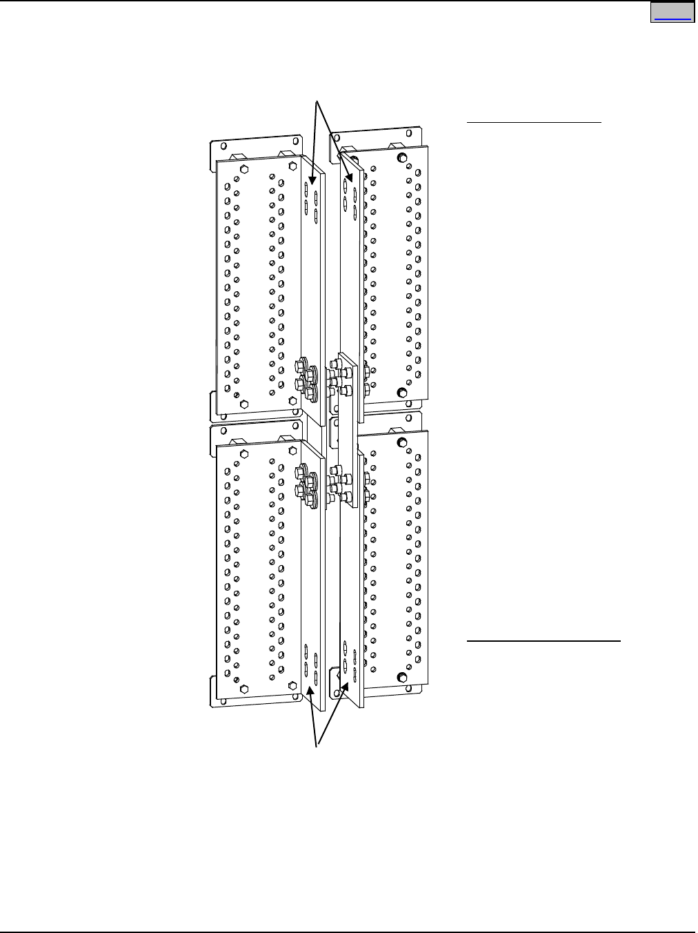
System Application Guide SAG582120600
Spec. No. 582120600 (Model 801DB NVGB) Issue BF, February 21, 2014
Page 63 of 72
This document is property of Emerson Network Power, Energy Systems, North America, Inc. and contains confidential and proprietary information owned by Emerson Network Power, Energy
Systems, North America, Inc. Any copying, use, or disclosure of it without the written permission of Emerson Network Power, Energy Systems, North America, Inc. is strictly prohibited.
Detail D (Page 3)
Optional List 117 Internal
Ground/Return Busbar
(List 127 similar)
Top Feed
DC Input Connections
(Battery Return Leads)
3/8" clearance holes on 1.00" centers
for installation of customer
provided two hole lugs.
(Torque to 180 in-lbs)
(Maximum Lug Width is 2.00")
(Maximum Wire Size is 4/0 AWG)
Top Feed Installations
Bottom Feed
DC Input Connections
(Battery Return Leads)
3/8" clearance holes on 1.00" centers
for installation of customer
provided two hole lugs.
(Torque to 180 in-lbs)
(Maximum Lug Width is 2.00")
(Maximum Wire Size is 4/0 AWG)
Bottom Feed Installations
Portion of bay removed
in illustration for clarity.
Rear View
8-Panel Bay
(6-Panel Bay Similar)
Home
SAG582120600 System Application Guide
Issue BF, February 21, 2014 Spec. No. 582120600 (Model 801DB NVGB)
Page 64 of 72
This document is property of Emerson Network Power, Energy Systems, North America, Inc. and contains confidential and proprietary information owned by Emerson Network Power, Energy
Systems, North America, Inc. Any copying, use, or disclosure of it without the written permission of Emerson Network Power, Energy Systems, North America, Inc. is strictly prohibited.
Replacement Alarm, Reference, and Control Fuses, List 105 and 107 Bays
Fuseblock Located in Bay’s Top Center
Features
♦ Control fuses are located on the fuseblock mounted in the top center of each bay.
Note also that distribution fuses also contain alarm-type fuses as detailed in the previous sections of this
document.
Restrictions
These fuses are not available for customer connected loads.
Ordering Notes
1) Order replacement fuses as required per Table 11.
Function Size
(Amperes) Type P/N
Top Fuse: Digital Meter and Alarm
Circuit Card Feed A (-48V Input). 1-1/3A Bussmann
GMT-A 248610700
Bottom Fuse: Digital Meter and Alarm
Circuit Card Feed B (-48V Input).
Safety Fuse Cover
Bussmann
GMT-X
248898700
Table 11
Replaceable Alarm, Reference, and Control Fuses, List 106 and 107 Bays
Replacement Alarm, Reference, and Control Fuses, List 106 and 108 Bays
Fuses Located on Auxiliary Fuse Card at Top of Bay
Features
♦ Control and auxiliary load fuses are located on the fuseblock mounted at the top right of each bay.
Note also that distribution fuses also contain alarm-type fuses as detailed in the previous sections of this
document.
Ordering Notes
1) Order replacement fuses as required per Table 12.
Function Size
(Amperes) Type P/N
F1, F2: Auxiliary loads, sourced from
Feed A (-48V).
1-1/3A Bussmann
GMT-A 248610700
F3, F4: Auxiliary loads, sourced from
Feed B (-48V).
F5, F6: External ABS (A&B) input to
Meter/Alarm Panel
Safety Fuse Cover Bussmann
GMT-X 248898700
Table 12
Replaceable Alarm, Reference, and Control Fuses, List 106 and 108 Bays
Home Home

System Application Guide SAG582120600
Spec. No. 582120600 (Model 801DB NVGB) Issue BF, February 21, 2014
Page 65 of 72
This document is property of Emerson Network Power, Energy Systems, North America, Inc. and contains confidential and proprietary information owned by Emerson Network Power, Energy
Systems, North America, Inc. Any copying, use, or disclosure of it without the written permission of Emerson Network Power, Energy Systems, North America, Inc. is strictly prohibited.
Replacement Circuit Cards, List 105 and 107 Bays
Ordering Notes
1) Refer to the following table.
Item P/N
External Alarm Circuit Card
486339800
Replacement Circuit Cards, List 106 and 108 Bays
Ordering Notes
1) Refer to the following table.
Item P/N
Auxiliary Fuse Card
547760
Input/Output Card
547761
Home

SAG582120600 System Application Guide
Issue BF, February 21, 2014 Spec. No. 582120600 (Model 801DB NVGB)
Page 66 of 72
This document is property of Emerson Network Power, Energy Systems, North America, Inc. and contains confidential and proprietary information owned by Emerson Network Power, Energy
Systems, North America, Inc. Any copying, use, or disclosure of it without the written permission of Emerson Network Power, Energy Systems, North America, Inc. is strictly prohibited.
SPECIFICATIONS
1.1 DC Operating Voltage
1.1.1 Nominal: -48Vdc.
1.1.2 Range: -42Vdc to -60Vdc.
1.2 Environmental Ratings
1.2.1 Operating Ambient Temperature Range: 0°C to +40°C (+32°F to +104°F).
1.2.2 Storage Ambient Temperature Range: -40°C to +80°C (-40°F to +176°F).
1.2.3 Humidity: This system is capable of operating in an ambient relative humidity range of 0% to
95%, non-condensing.
1.2.4 Altitude: The maximum operating ambient temperature should be de-rated by 10°C at an
elevation of 10,000 feet above sea level. For elevations between 3,000 feet and 10,000 feet,
derate the maximum operating ambient temperature linearly.
1.2.5 Mounting: This product is intended only for installation in a Restricted Access Location on or
above a non-combustible surface.
Typical industry standards recommend minimum aisle space clearance of 2'6" for the front of
the relay rack and 2' for the rear of the relay rack.
This BDF/CBB uses natural convection. Equipment designed for use in environmentally
controlled space.
This product is intended for installation in Network Telecommunication Facilities (CO, vault,
hut, or other environmentally controlled electronic equipment enclosure).
This product is intended to be connected to the common bonding network in a Network
Telecommunication Facility (CO, vault, hut, or other environmentally controlled electronic
equipment enclosure).
1.3 Compliance Information
1.3.1 Safety Compliance: This BDF/CBB is UL Listed (and "cULus") as a DC Power Distribution
Center for Communications Equipment.
1.3.2 NEBS Compliance: Compliance verified by a Nationally Recognized Testing Laboratory
(NRTL) per GR-1089-CORE and GR-63-CORE. Contact Emerson Network Power for NEBS
compliance reports.
1.4 Output Ratings
1.4.1 Distribution Panel: 640A maximum continuous.
1.4.2 8-Panel Bay: 2400A, maximum, per side.
4800A, maximum, per bay.
1.4.3 6-Panel Bay: 1800A, maximum, per side.
3600A, maximum, per bay.
1.5 Standard Features—Lists 105 and 107
1.5.1 Fuse/Circuit Breaker Mounting Positions: See description in Distribution Panel List Options
section.
1.5.2 External Alarm Circuits: Three (3) Form-C relay contacts provided for external fuse / circuit
breaker alarms.
1.5.3 Local Controls and Indicators: A digital meter is furnished for load voltage and distribution
panel current monitoring. Each distribution panel has a green indicator which illuminates when
power is being supplied to the panel, and a red indicator which illuminates if a fuse or circuit
breaker within the panel opens.
1.5.4 Meter Accuracy
(A) Current: ±1A
(B) Voltage: ±0.5V
Home
Home

System Application Guide SAG582120600
Spec. No. 582120600 (Model 801DB NVGB) Issue BF, February 21, 2014
Page 67 of 72
This document is property of Emerson Network Power, Energy Systems, North America, Inc. and contains confidential and proprietary information owned by Emerson Network Power, Energy
Systems, North America, Inc. Any copying, use, or disclosure of it without the written permission of Emerson Network Power, Energy Systems, North America, Inc. is strictly prohibited.
1.6 Standard Features—Lists 106 and 108
1.6.1 Fuse/Circuit Breaker Mounting Positions: See description in Distribution Panel
List Options section.
1.6.2 External Alarm Circuits: Four (4) relays each provide three (3) sets of Form-C contacts for
external alarms. Various available alarms can be mapped to each of the relays. Contact rating
is 2A at 30 VDC.
1.6.3 Local Controls and Indicators: A status indicator at the top of the bay front panel indicates
system status. The Meter/Alarm Panel provides digital metering of load voltage and current
individually for each distribution panel. Also displays system alarm messages and adjustment
information.
1.6.4 Meter Accuracy
(A) Current: ±1.0%
(B) Voltage: ±0.1%
1.6.5 Remote Access: Via Web Interface
(A) Description: The Web Interface provides remote access to the system monitoring and
control functions that are available locally at the Meter/Control Panel.
(B) Connection: Ethernet, RJ 45 10BaseT jack. This jack has a standard Ethernet pin
configuration scheme, twisted pair. Use shielded Ethernet cable, grounded at both ends.
(The Meter/Alarm Panel’s RJ-45 jack is connected to chassis ground.) The Ethernet port is
suitable for connection to intra-building or non-exposed wiring or cabling only.
(C) Users: 64, maximum
(D) Security:
(1) Password Protection: When logging onto the system, the user is prompted to enter a
"User Password".
(2) Page Access Levels: User configurations provide a "Page Access Level" which can be
used to limit the functions available to a particular user. Eight Page Access Levels are
available.
(E) PC Requirements:
(1) Web Browser: Microsoft® Internet Explorer 5.0 or newer is required.
(2) Screen Resolution: 1024 x 768 or greater is required.
Home
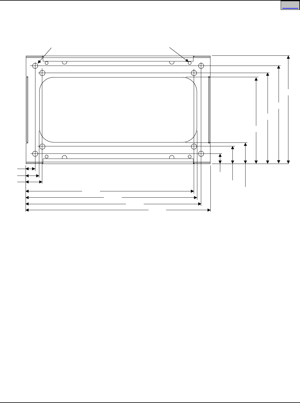
SAG582120600 System Application Guide
Issue BF, February 21, 2014 Spec. No. 582120600 (Model 801DB NVGB)
Page 68 of 72
This document is property of Emerson Network Power, Energy Systems, North America, Inc. and contains confidential and proprietary information owned by Emerson Network Power, Energy
Systems, North America, Inc. Any copying, use, or disclosure of it without the written permission of Emerson Network Power, Energy Systems, North America, Inc. is strictly prohibited.
PHYSICAL SIZE INFORMATION
Floor Hole Drilling Pattern Dimensions
Front
3/8-16
Welded Nut (4)
0.750 Dia.
(8 PLACES)
2.275
1.275
1.875
26.000
23.875
23.475
24.475
1.400
2.400
3.000
12.096
12.696
13.696
15.000
Home
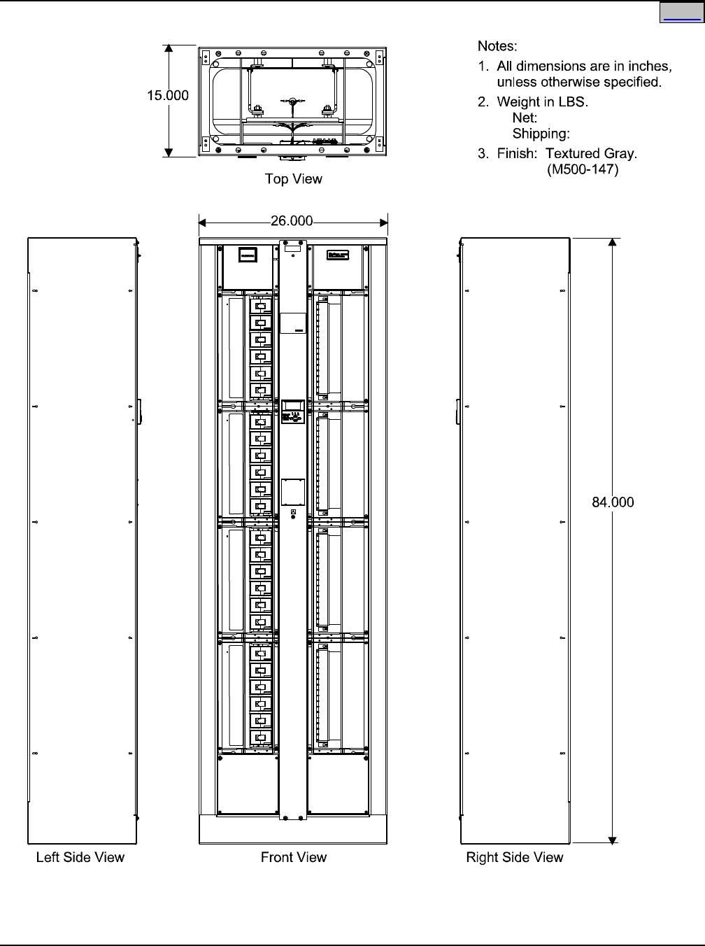
System Application Guide SAG582120600
Spec. No. 582120600 (Model 801DB NVGB) Issue BF, February 21, 2014
Page 69 of 72
This document is property of Emerson Network Power, Energy Systems, North America, Inc. and contains confidential and proprietary information owned by Emerson Network Power, Energy
Systems, North America, Inc. Any copying, use, or disclosure of it without the written permission of Emerson Network Power, Energy Systems, North America, Inc. is strictly prohibited.
Dimensions, 8-Bus Bay
Home
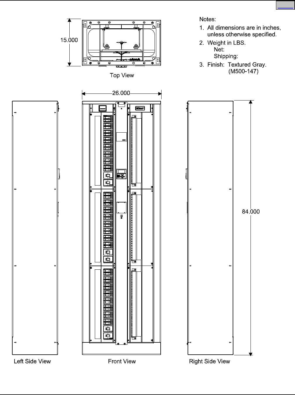
SAG582120600 System Application Guide
Issue BF, February 21, 2014 Spec. No. 582120600 (Model 801DB NVGB)
Page 70 of 72
This document is property of Emerson Network Power, Energy Systems, North America, Inc. and contains confidential and proprietary information owned by Emerson Network Power, Energy
Systems, North America, Inc. Any copying, use, or disclosure of it without the written permission of Emerson Network Power, Energy Systems, North America, Inc. is strictly prohibited.
Dimensions, 6-Bus Bay
Home

System Application Guide SAG582120600
Spec. No. 582120600 (Model 801DB NVGB) Issue BF, February 21, 2014
Page 71 of 72
This document is property of Emerson Network Power, Energy Systems, North America, Inc. and contains confidential and proprietary information owned by Emerson Network Power, Energy
Systems, North America, Inc. Any copying, use, or disclosure of it without the written permission of Emerson Network Power, Energy Systems, North America, Inc. is strictly prohibited.
RELATED DOCUMENTATION
Schematic Diagram: SD582120600 (Power System)
Wiring Diagram: T582120600 (Power System)
Instructions: Section 5674 (Power System)
Section 5823 (Pre-charge Assembly, Spec. No. 510142)
Load and Battery Lug Detail Drawings: 031110100 through 031110300
Home

SAG582120600 System Application Guide
Issue BF, February 21, 2014 Spec. No. 582120600 (Model 801DB NVGB)
Page 72 of 72
This document is property of Emerson Network Power, Energy Systems, North America, Inc. and contains confidential and proprietary information owned by Emerson Network Power, Energy
Systems, North America, Inc. Any copying, use, or disclosure of it without the written permission of Emerson Network Power, Energy Systems, North America, Inc. is strictly prohibited.
REVISION RECORD
Issue
Change
Number
(ECO)
Description of Change Date Approved
BB LLP218226 Add new busbar kit P/N 556103. 02/22/2013 Khristebelle
Ilagan
BC LLP218456
Add right angle lug adapter kits P/Ns 556377
and 556378. 05/01/2013 John Jasko
BD LLP219017
Auxiliary Fuse Card Connections illustration
revised. Removed rocker handle bullet-nose
circuit breakers. Revised notes for 556103.
Added “Side by Side Busbar Link Kit for Use
with List 115 and List 125, P/N 557256”.
09/03/2013 John Jasko
BE LLP219319
Illustration for List 170 added. Relay and alarm
settings defaults added to “Ethernet and
External Alarm Connections” illustration, Detail
B for List 106 and 108.
12/03/2013 John Jasko
BF LLP219853
Added 90A Bullet Breaker P/Ns 138887 and
138888.
02/21/2014 John Jasko
Home
Emerson Network Power, Energy Systems, North America, Inc.
4350 Weaver Parkway, Warrenville, IL 60555
Toll Free:
800-800-1280 (USA and Canada)
Telephone:
440-246-6999 Fax: 440-246-4876
Web:
EmersonNetworkPower.com/EnergySystems
EnergyNet:
Secure.EmersonNetworkPower.com
John Jasko
Mar 6, 2014
Fortune Huang
Mar 7, 2014
