Emerson Sw375 Owners Manual BP7424
2015-03-30
: Emerson Emerson-Sw375-Owners-Manual-682000 emerson-sw375-owners-manual-682000 emerson pdf
Open the PDF directly: View PDF ![]() .
.
Page Count: 4
Part No. F40BP74240000 Form No. BP7424
READ AND SAVE THESE INSTRUCTIONS
Replacement of
SW375 Receiver
With SW105 or
RCK55 Receiver
Owner's Manual
Safety Instructions
WARNING: To avoid fire, shock, and serious personal injury, follow all instructions
carefully.
1. Read your Owner's Manual carefully before installing the Receiver. Retain Owner's
Manual for future reference.
2. Before servicing or cleaning the ceiling fan, switch power off at service panel and lock
service panel to prevent power from being switched on accidentally. When the service
disconnecting means cannot be locked, securely fasten a warning device such as a
tag, to the service panel.
ADDITIONAL SAFETY INSTRUCTIONS FOR INSTALLATION
1. To avoid possible electrical shock, be sure electricity is turned off at the main fuse or
circuit breaker box before wiring.
2. Make certain no bare wires are exposed outside the wire connectors.
3. All wiring must conform to National and Local Electrical Codes.
4. Follow the recommended instructions for the proper method of wiring your new
Receiver. If you feel you do not have enough electrical wiring knowledge or
experience, have your Receiver installed by a licensed electrician. Any electrical work
not described in this manual should be performed by a licensed electrician.
INSTRUCTION TO THE USER (if device contains a digital device)
This equipment has been tested and found to comply with the limits for a class B digital device, pursuant
to part 15 of the FCC Rules. These limits are designed to provide reasonable protection against harmful
interference in a residential installation. This equipment generates, uses and can radiate radio frequency
energy and if not installed and used in accordance with the instructions, may cause harmful interference to
radio communications. However, there is no guarantee that interference will not occur in a particular
installation. If this equipment does cause harmful interference to radio or television reception, which can
be determined by turning the equipment off and on, the user is encouraged to try to correct the interference
by one or more of the following measures:
• Reorient or relocate the receiving antenna.
• Increase the separation between the equipment and receiver.
• Connect the equipment into an outlet on a circuit different from that to which the receiver is connected.
• Consult the dealer or an experienced radio/TV technician for help.
This equipment has been certified to comply with the limits for a class B computing device, pursuant to FCC
Rules. In order to maintain compliance with FCC regulations, shielded cables must be used with this
equipment. Operation with non-approved equipment or unshielded cables is likely to result in interference
to radio and TV reception. The user is cautioned that changes and modifications made to the equipment
without the approval of manufacturer could void the user’s authority to operate this equipment.
This Class B digital apparatus meets all requirements of the Canadian
Interference-Causing Equipment Regulations.
!WARNING
BP7424 SW375 7/7/10 3:45 PM Page 1
2
General
Your Owner’s Manual contains instructions
for the replacement of your old SW375
Receiver, located under the ceiling cover,
with a new SW105 or RCK55 Receiver.
Removal of switch(es) and the capacitor in
the switch housing, installation of a
reversing module in the switch housing, and
wiring alterations under the motor cover are
changes that must be made, in addition to
replacement of the receiver.
NOTE: Your ceiling fan does not have to
be removed from the ceiling in order to
facilitate these changes.
IMPORTANT
The new SW105 or RCK55 Receiver must
NOT be used with your existing SR330
Remove Control or SW115 Wall Control.
Unpackaging
The SW105 or RCK55 Receiver carton
also contains a reversing module, two wire
connectors, and four pull chain plugs.
Replacement Procedures
IMPORTANT
It is important that you also follow the
instructions contained in the Owner’s
Manual supplied with your Ceiling Fan.
Pay particular attention to the Safety
Instructions and the WARNING notes.
Turning off wall switch is not sufficient.
To avoid possible electrical shock, be
sure electricity is turned off at the main
fuse or circuit breaker box before wiring.
All wiring must be in accordance with
National and Local codes and the ceiling
fan must be properly grounded as a
precaution against possible electrical
shock.
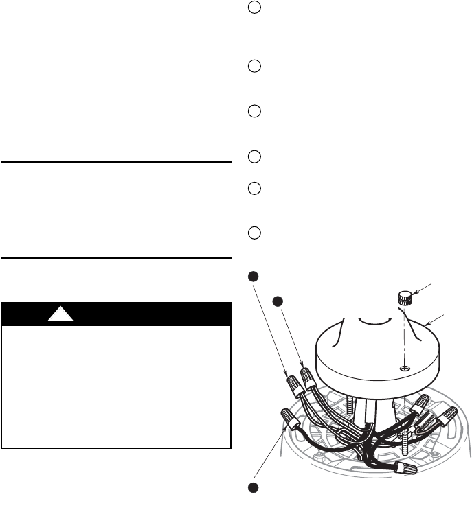
!WARNING MOTOR
COVER
REMOVE WIRE CONNECTOR FROM BLACK
WIRE AND STRIP OFF 1/2" INSULATION
KNURLED
KNOB
REMOVE WIRE CONNECTOR
FROM TWO RED WIRES
A
B
EREMOVE WIRE CONNECTOR
FROM TWO BROWN WIRES
Figure 1
1. Remove the two knurled knobs
securing the motor cover to the top of
the motor (Figure 1)
2. Raise the motor cover up the downrod
to expose the wiring under the cover.
Refer to Figures 1 and 2 and the
following wiring diagrams, Figures 3
and 5, and make the following
changes:
Remove the wire connector from the
black wire (Figures 1 and 3). Strip back
insulation 1/2-inch from the end of the
black wire.
Remove the wire connector joining the
two red wires (Figures 1 and 3) and
separate the wires.
Join the black wire (Step A) to the red
wire coming from the downrod using a
wire connector (Figures 2 and 5).
Cap the red wire coming from the motor
using a wire connector (Figures 2 and 5).
Remove the wire connector joining the
two brown wires (Figures 1 and 3) and
separate the wires.
Cap each of the brown wires separately
using wire connectors (Figures 2 and 5).
A
B
C
D
E
F
BP7424 SW375 7/7/10 3:45 PM Page 2
3
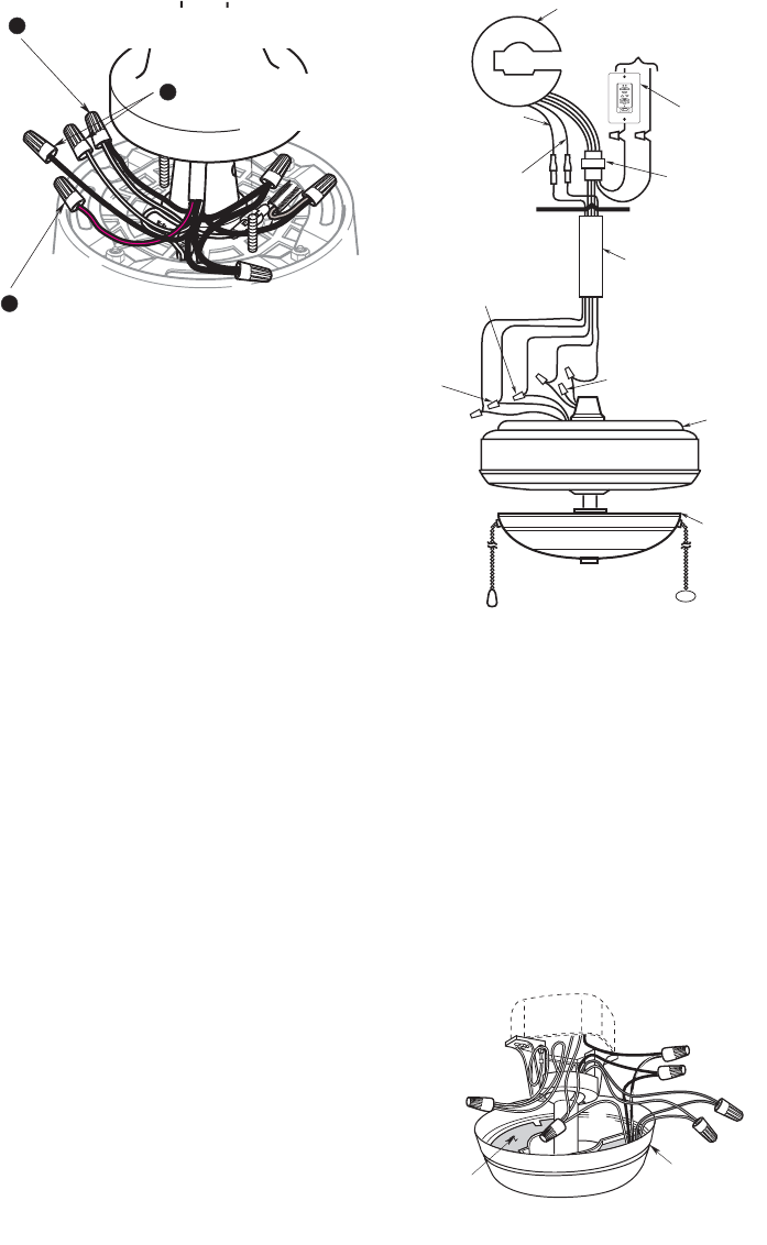
CAP THE RED WIRE FROM THE MOTOR
USING A WIRE CONNECTOR
D
JOIN THE BLACK WIRE TO THE RED WIRE FROM
THE DOWNROD USING A WIRE CONNECTOR
F
C
CAP EACH OF THE BROWN
WIRES USING WIRE
CONNECTORS
Figure 2
Off On
Up Down
Lights
Fan
Sleep
FAN BLADES REMOVED
FOR CLARITY
REMOVE WIRE
CONNECTOR
FROM BROWN
WIRES REMOVE WIRE CONNECTOR
FROM BLACK WIRE
REMOVE WIRE
CONNECTOR FROM
BLACK WIRE
LIGHT
FIXTURE
FAN
HOUSING
DOWNROD
DISCONNECT YELLOW
WIRES (Built-in Up
Light Only)
DISCONNECT
BLUE WIRES
REMOVE SW375 RECEIVER
TO
120V SUPPLY REMOVE
OPTIONAL
EMERSON
SW350 WALL
CONTROL OR
USE ON/OFF
WALL SWITCH
DISCONNECT
RECEIVER
CONNECTOR
FROM WIRING
HARNESS
CUT LEADS
WIRING DIAGRAM - SW375 RECEIVER REMOVAL
Figure 3
3. Slide the motor cover down the
downrod and secure using the knurled
knobs previously removed (Figure 1).
4. Remove the two knurled knobs and
lockwashers securing the ceiling cover
to the hanger bracket. Slide the ceiling
cover down the downrod until it rests on
the motor cover.
5. Disconnect the SW375 Receiver four-
pin connector from the wiring harness
connector coming from the downrod
(Figure 3).
6. Disconnect the connectors on the
SW375 Receiver blue wire and yellow
wire from the connectors on the blue
wire and yellow wire (if present) coming
from the downrod (Figure 3).
NOTE: If your fan does not have an
uplight, the yellow wire from the
downrod will not be present.
7. Remove the SW375 Receiver.
8. The SW105 Receiver will need to be
programed before installing into the
canopy as instructed in the receiver
owner’s manual. Your Emerson remote
control receiver is equipped with a
preset memory feature. The receiver
will remember the light intensities and
fan speed when the lights and fan are
turned off from the wall switch. When
the wall switch is turned back on, the
lights and fan will resume operation as
they were prior to being turned off.
9. Position the SW105 or RCK55
Receiver in the ceiling cover so that the
flat side of the receiver faces up and
the open portion of the receivers to the
right, as shown in Figure 4. Cut the two
single pin connectors off the blue and
yellow wires. Cut the four pin connector
off the main harness. Cut as close to
the bottom of the connectors as
possible.
10. Cap the brown lead and strip all other
leads approximately 1/2”.
SW105 or RCK55
RECEIVER
CEILING COVER
OPEN
PORTION OF
RECEIVER
HERE
Figure 4
BP7424 SW375 7/7/10 3:45 PM Page 3
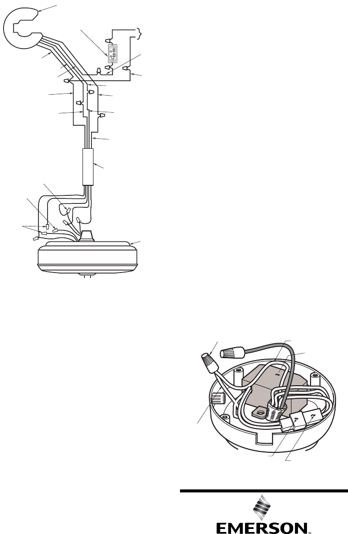
LISTED GENERAL USE ON/OFF WALL
SWITCH OR OPTIONAL EMERSON
SR110 WALL CONTROL
CAP
BROWN
WIRES
CAP RED
WIRE
FAN
HOUSING
DOWNROD
CONNECT BLACK
AND RED WIRES
WHITE
SUPPLY
WIRE
RED FAN WIRE
INSTALL SW105 OR RCK55 RECEIVER
TO
110V
SUPPLY
YELLOW RECEIVER
WIRE**
WHITE FAN WIRE
BLUE RECEIVER WIRE*
BLUE FAN WIRE
BLACK
SUPPLY
WIRE
WHITE
RECEIVER WIRE
BLACK RECEIVER WIRE
BLACK/WHITE
RECEIVER WIRE
YELLOW FAN WIRE
(FROM UPLIGHT)
WIRING DIAGRAM - SW105 OR RCK55 RECEIVER
INSTALLATION. Figure 5
CAUTION: If your ceiling fan does NOT
have an uplight, there will be NO yellow
fan wire. In this case, cap the yellow
receiver wire using a wire connector
(supplied). If your ceiling fan does NOT
have a downlight, cap the blue receiver
wire using a wire connector (supplied).
12. Remove and retain the screws
securing the housing cover to the
switch housing.
13. Disconnect the motor connector from
the wiring harness connector. Remove
the knurled nut securing the speed
control switch to the switch housing.
14. Position the reversing module
(supplied) in the switch cup; connect
the reversing module connector to the
motor connector (Figure 6). The
connectors are color-coded and keyed
and can be connected in only one
manner.
15. Using a wire connector (supplied),
connect the white wire from the motor
to the reversing module white wire
(Figure 6).
16. Position the housing cover on the
switch housing and secure using the
screws removed in Step 12.
17. Complete the installation and
operation per manual supplied with
your new remote control.
11. Using wire connectors (supplied),
make wiring connections as follows
(Figure 5):
a. Connect the green ground wires from
the hanger bracket and the hanger ball
to the supply ground wire (bare or
green).
b. Connect the white fan wire and the
white supply wire to the white receiver
wire (AC IN/MOTOR N).
c. Connect the red fan wire to the black
receiver wire (TO MOTOR L).
d. Connect the black supply wire to the
black/white receiver wire (AC IN L).
e. Cut off the end of the blue and yellow
receiver wires and strip back insulation
1/2” from the end of the wires.
f. Connect the blue fan wire to the blue
receiver wire (BOTTOM LIGHT).
g. Connect the yellow fan wire to the
yellow receiver wire (UPPER
LIGHT).
Part No. F40BP74240000 Printed in China 07/10 Form No. BP7424
Air Comfort Products
DIVISION OF EMERSON ELECTRIC CO.
8100 W. Florissant • St. Louis, MO 63136
WIRE CONNECTOR
REVERSING
MODULE
MOTOR
CONNECTOR
WHITE
REVERSING
MODULE WIRE
WHITE MOTOR
WIRE
REVERSING MODULE
CONNECTOR
Figure 6
BP7424 SW375 7/7/10 3:45 PM Page 4
