Emerson Turbine Meter 1500 Installation And Operation Manual Daniel Series 3 18 Inch Sizes
Emerson turbine meter 3-9008-504 1500-Turbine-Meter-3-18in-sizes-Installation-and-Operation-Manual-3-9008-504
1500 to the manual 0dca1b79-4619-4f67-9e1f-bdaa3f3f720e
2015-01-05
: Emerson Emerson-Turbine-Meter-1500-Installation-And-Operation-Manual-165660 emerson-turbine-meter-1500-installation-and-operation-manual-165660 emerson pdf
Open the PDF directly: View PDF ![]() .
.
Page Count: 60
Installation and operation manual
Part Number 3-9008-504, rev. K
October, 2013
DanielTM Series 1500 turbine meter
3" thru 18" sizes
Safety signal words and symbols
Pay special attention to the following signal words, safety alert symbols and statements:
Safety alert symbol
This is a safety alert symbol. It is used to alert you to potential physical injury hazards. Obey all
safety messages that follow this symbol to avoid possible injury or death.
Indicates a hazardous situation which, if not avoided, will result in death or serious injury.
Warning indicates a hazardous situation which, if not avoided, could result in death or serious
injury.
Caution indicates a hazardous situation which, if not avoided, could result in minor or moderate
injury.
Notice is used to address safety messages or practices not related to personal injury.

Important safety instructions
Daniel Measurement and Control, Inc. (Daniel) designs, manufactures and tests products to
function within specific conditions. Because these products are sophisticated technical
instruments, it is important that the owner and operation personnel must strictly adhere both to
the information printed on the product and to all instructions provided in this manual prior to
installation, operation, and maintenance.
Daniel also urges you to integrate this manual into your training and safety program.
BE SURE ALL PERSONNEL READ AND FOLLOW THE INSTRUCTIONS IN THIS
MANUAL AND ALL NOTICES AND PRODUCT WARNINGS.
Failure to follow the installation, operation or maintenance instructions for a Daniel
product could lead to serious injury or death from explosion or exposure to dangerous
substances.
To reduce this risk:
• Comply with all information on the product, in this manual, and in any local and
national codes that apply to the product.
• Do not allow untrained personnel to work with this product.
• Use Daniel parts and work procedures specified in this manual.
Product owners (Purchasers):
• Use the correct product for the environment and pressures present. See technical data or
product specifications for limitations. If you are unsure, discuss your needs with your
Daniel representative.
• Inform and train all personnel in the proper installation, operation, and maintenance of
this product.
• To ensure safe and proper performance, only informed and trained personnel should
install, operate, repair and maintain this product.
• Verify that this is the correct instruction manual for your Daniel product. If this is not the
correct documentation, contact Daniel at 1-713-827-6314. You may also download the
correct manual from: http://www.daniel.com
• Save this instruction manual for future reference.
• If you resell or transfer this product, it is your responsibility to forward this instruction
manual along with the product to the new owner or transferee.
• ALWAYS READ AND FOLLOW THE INSTALLATION, OPERATIONS,
MAINTENANCE AND TROUBLESHOOTING MANUAL(S) AND ALL PRODUCT
WARNINGS AND INSTRUCTIONS.
• Do not use this equipment for any purpose other than its intended service. This may
result in property damage and/or serious personal injury or death.
Product operation personnel:
• To prevent personal injury, personnel must follow all instructions of this manual prior to and
during operation of the product. Follow all warnings, cautions, and notices marked on, and
supplied with, this product.
• Verify that this is the correct instruction manual for your Daniel product. If this is not the
correct documentation, contact Daniel at 1-713-827-6314. You may also download the
correct manual from: http://www.daniel.com
• Read and understand all instructions and operating procedures for this product.
• If you do not understand an instruction, or do not feel comfortable following the instructions,
contact your Daniel representative for clarification or assistance.
• Install this product as specified in the INSTALLATION section of this manual per
applicable local and national codes.
• Follow all instructions during the installation, operation, and maintenance of this product.
• Connect the product to the proper pressure sources when and where applicable.
• Ensure that all connections to pressure and electrical sources are secure prior to, and during,
equipment operation.
• Use only replacement parts specified by Daniel. Unauthorized parts and procedures can
affect this product's performance, safety, and invalidate the warranty. "Look-a-like"
substitutions may result in deadly fire, explosion, release of toxic substances or improper
operation.
• Save this instruction manual for future reference.
Notice
THE CONTENTS OF THIS PUBLICATION ARE PRESENTED FOR INFORMATIONAL PURPOSES ONLY,
AND WHILE EVERY EFFORT HAS BEEN MADE TO ENSURE THEIR ACCURACY, THEY ARE NOT TO
BE CONSTRUED AS WARRANTIES OR GUARANTEES, EXPRESSED OR IMPLIED, REGARDING THE
PRODUCTS OR SERVICES DESCRIBED HEREIN OR THEIR USE OR APPLICABILITY. ALL SALES ARE
GOVERNED BY DANIEL’S TERMS AND CONDITIONS, WHICH ARE AVAILABLE UPON REQUEST. WE
RESERVE THE RIGHT TO MODIFY OR IMPROVE THE DESIGNS OR SPECIFICATIONS OF SUCH
PRODUCTS AT ANY TIME.
DANIEL DOES NOT ASSUME RESPONSIBILITY FOR THE SELECTION, USE OR MAINTENANCE OF
ANY PRODUCT. RESPONSIBILITY FOR PROPER SELECTION, USE AND MAINTENANCE OF ANY
DANIEL PRODUCT REMAINS SOLELY WITH THE PURCHASER AND END-USER.
TO THE BEST OF DANIEL’S KNOWLEDGE THE INFORMATION HEREIN IS COMPLETE AND
ACCURATE. DANIEL MAKES NO WARRANTIES, EXPRESSED OR IMPLIED, INCLUDING THE IMPLIED
WARRANTIES OF MERCHANTABILITY AND FITNESS FOR A PARTICULAR PURPOSE WITH RESPECT
TO THIS MANUAL AND, IN NO EVENT, SHALL DANIEL BE LIABLE FOR ANY INCIDENTAL, PUNITIVE,
SPECIAL OR CONSEQUENTIAL DAMAGES INCLUDING, BUT NOT LIMITED TO, LOSS OF
PRODUCTION, LOSS OF PROFITS, LOSS OF REVENUE OR USE AND COSTS INCURRED INCLUDING
WITHOUT LIMITATION FOR CAPITAL, FUEL AND POWER, AND CLAIMS OF THIRD PARTIES.
PRODUCT NAMES USED HEREIN ARE FOR MANUFACTURER OR SUPPLIER IDENTIFICATION ONLY
AND MAY BE TRADEMARKS/REGISTERED TRADEMARKS OF THESE COMPANIES.
Warranty and limitation of liability
1. LIMITED WARRANTY: Subject to the limitations contained in Section 2 herein, Daniel Measurement & Control,
Inc. (“Daniel”) warrants that the licensed firmware embodied in the Goods will execute the programming instructions
provided by Daniel, and that the Goods manufactured by Daniel will be free from defects in materials or workmanship
under normal use and care and Services will be performed by trained personnel using proper equipment and
instrumentation for the particular Service provided. The foregoing warranties will apply until the expiration of the
applicable warranty period. Goods are warranted for twelve (12) months from the date of initial installation or eighteen
(18) months from the date of shipment by Daniel, whichever period expires first. Consumables and Services are
warranted for a period of 90 days from the date of shipment or completion of the Services. Products purchased by Daniel
from a third party for resale to Buyer (“Resale Products”) shall carry only the warranty extended by the original
manufacturer. Buyer agrees that Daniel has no liability for Resale Products beyond making a reasonable commercial
effort to arrange for procurement and shipping of the Resale Products. If Buyer discovers any warranty defects and
notifies Daniel thereof in writing during the applicable warranty period, Daniel shall, at its option, correct any errors that
are found by Daniel in the firmware or Services or repair or replace F.O.B. point of manufacture that portion of the
Goods or firmware found by Daniel to be defective, or refund the purchase price of the defective portion of the
Goods/Services. All replacements or repairs necessitated by inadequate maintenance, normal wear and usage, unsuitable
power sources or environmental conditions, accident, misuse, improper installation, modification, repair, use of
unauthorized replacement parts, storage or handling, or any other cause not the fault of Daniel are not covered by this
limited warranty, and shall be at Buyer’s expense. Daniel shall not be obligated to pay any costs or charges incurred
by Buyer or any other party except as may be agreed upon in writing in advance by Daniel. All costs of dismantling,
reinstallation and freight and the time and expenses of Daniel’s personnel and representatives for site travel and diagnosis
under this warranty clause shall be borne by Buyer unless accepted in writing by Daniel. Goods repaired and parts
replaced by Daniel during the warranty period shall be in warranty for the remainder of the original warranty period or
ninety (90) days, whichever is longer. This limited warranty is the only warranty made by Daniel and can be amended
only in a writing signed by Daniel. THE WARRANTIES AND REMEDIES SET FORTH ABOVE ARE EXCLUSIVE.
THERE ARE NO REPRESENTATIONS OR WARRANTIES OF ANY KIND, EXPRESS OR IMPLIED, AS TO
MERCHANTABILITY, FITNESS FOR PARTICULAR PURPOSE OR ANY OTHER MATTER WITH RESPECT
TO ANY OF THE GOODS OR SERVICES. Buyer acknowledges and agrees that corrosion or erosion of materials is
not covered by this warranty.
2. LIMITATION OF REMEDY AND LIABILITY: Daniel shall not be liable for damages caused by delay in
performance. The remedies of buyer set forth in this agreement are exclusive. In no event, regardless of the form of the
claim or cause of action (whether based in contract, infringement, negligence, strict liability, other tort or otherwise),
shall Daniel’s liability to buyer and/or its customers exceed the price to buyer of the specific goods manufactured or
services provided by Daniel giving rise to the claim or cause of action. Buyer agrees that in no event shall Daniel’s
liability to buyer and/or its customers extend to include incidental, consequential or punitive damages. The term
“consequential damages” shall include, but not be limited to, loss of anticipated profits, revenue or use and costs incurred
including without limitation for capital, fuel and power, and claims of buyer’s customers.

DANIEL™ SERIES 1500 TURBINE METER OCT 2013
TABLE OF CONTENTS i
TABLE OF CONTENTS
1.0 INTRODUCTION .................................................... 1-1
1.1 General........................................................ 1-1
1.2 Description..................................................... 1-1
2.0 SPECIFICATIONS ................................................... 2-1
3.0 INSTALLATION..................................................... 3-1
3.1 General........................................................ 3-1
3.2 Flow Considerations ............................................. 3-1
3.3 Installation and Equipment ........................................ 3-2
3.4 Pickoff Coils and Electrical Connections ............................. 3-6
4.0 OPERATION ........................................................ 4-1
4.1 General........................................................ 4-1
4.2 Pre-start Checks ................................................. 4-1
4.3 Operation ...................................................... 4-2
5.0 MAINTENANCE ..................................................... 5-1
5.1 General........................................................ 5-1
5.2 Maintenance Considerations ....................................... 5-1
5.3 Disassembly Procedures Internal Components ......................... 5-2
5.4 Reassembly of Internal Components ................................. 5-7
5.5 Field Retrofitable Dual Pickoff ..................................... 5-8
6.0 TROUBLESHOOTING ............................................... 6-1
6.1 General........................................................ 6-1
7.0 PARTS LIST ........................................................ 7-1

OCT 2013 DANIEL™ SERIES 1500 TURBINE METER
TABLE OF CONTENTSii
This page intentionally left blank.

DANIEL™ SERIES 1500 TURBINE METER OCT 2013
TABLE OF CONTENTS iii
Figures
3-1 Typical Installation .................................................... 3-2
3-2 UMB Wiring ......................................................... 3-7
7-1 UMB Assembly - All Sizes .............................................. 7-2
7-2 High Temperature UMB Assembly........................................ 7-4
7-3 Meter Assembly - Sizes 3" through 18" Uni-Directional ....................... 7-6
7-4 Meter Assembly - Sizes 4" through 8" Bi-Directional ......................... 7-8
7-5 Meter Assembly - Sizes 10" through 12" Uni-Directional ..................... 7-10
7-6 Meter Assembly - Sizes 16" through 18" Uni-Directional ..................... 7-12
Tables
5-1 Torque Values for Shaft Nut Installation.................................... 5-7
6-1 Troubleshooting ....................................................... 6-1
7-1 UMB Assembly - All Sizes .............................................. 7-3
7-2 High Temperature UMB Assembly........................................ 7-5
7-3 Meter Assembly - Sizes 3" through 8" Uni-Directional ........................ 7-7
7-4 Meter Assembly - Sizes 4" through 8" Bi-Directional ......................... 7-9
7-5 Meter Assembly - Sizes 10" through 12" Uni-Directional ..................... 7-11
7-6 Meter Assembly - Sizes 16" through 18" Uni-Directional ..................... 7-13

OCT 2013 DANIEL™ SERIES 1500 TURBINE METER
TABLE OF CONTENTSiv
This page intentionally left blank.
DANIEL™ SERIES 1500 TURBINE METER OCT 2013
INTRODUCTION 1-1
1.0 INTRODUCTION
1.1 General
This manual is designed to assist in the installation and operation of the Daniel™ Series 1500
Turbine Meter. To assure proper installation and startup it is important to read this manual in its
entirety.
1.2 Description
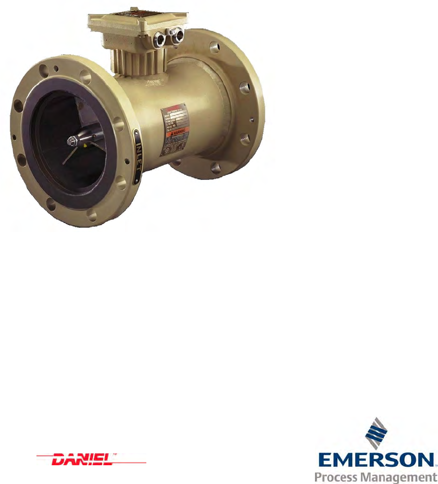
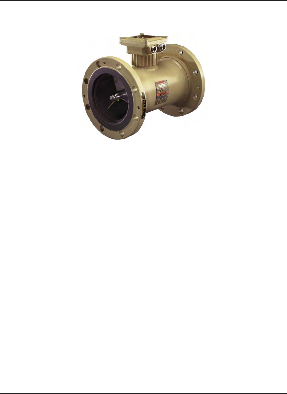
The Series 1500 Turbine Flowmeter is a volumetric flow metering and transmitting device used
extensively in the petroleum industry for the accurate measurement of hydrocarbon and other related
process fluids. The meter's clean lines and simple configuration assures higher flow rates,
extended flow range and sustained performance capability.
The UMB (Universal Mounting Box) provides an explosion proof, weather resistant housing for
both single or dual pickoffs as well as the preamplifier board. An optional dual UMB is available
to house additional dual pickoff coils and preamplifier board. The UMB serves as the mechanical
mounting connection necessary for local and remote accessories.
The Series 1500 Turbine is ideal for applications requiring high frequency resolution. Applications
may include systems with flow computers or any component of the Daniel preset family of
petroleum management equipment.

OCT 2013 DANIEL™ SERIES 1500 TURBINE METER
INTRODUCTION1-2
This page intentionally left blank.
DANIEL™ SERIES 1500 TURBINE METER OCT 2013
SPECIFICATIONS 2-1
2.0 SPECIFICATIONS
This meter is designed for use within the guidelines of API Standards, Chapter 5.3, formerly
Standard 2534 (The Measurement of Liquid Hydrocarbons by Turbine Meter Systems) and the test
procedures of API Standards, Chapter 4 (Prover Systems).
PERSONAL INJURY AND/OR EQUIPMENT DAMAGE
Do not exceed specifications listed below.
Failure to heed this warning could result in serious injury and/or damage to the equipment.
Approvals:
Electrical: UL and ULC: Class I, Division 1, Groups C & D
DEMKO 03 ATEX 130946X
IECEx UL 11.0031X
Environmental NEMA 4
NEMA 4 UL
Metrology NMi TC7573
ATEX certification
Standard temperature
Optional temperature

OCT 2013 DANIEL™ SERIES 1500 TURBINE METER
SPECIFICATIONS2-2
INMETRO certification
Certification number
and marking
Applicable norms ABNT NBR IEC 60079-0:2008
ABNT NBR IEC 60079-1:2009
Temperature range -40/C # to # +60/C
Conditions for safe use (X) - The joint between the Universal Mounting Box cover and
housing is a flat joint and has a flame path of 9,52 mm in
length and clearance of less than 0,0381 mm.
- The joint between the Universal Mounting Box housing
and Sensor housing is a spigot joint which has a radial
length of 3,18 mm, an axial length of 13,61 mm and a
clearance of 0,059 mm.
- Device is to be remote-mounted when the process
temperature is outside of the ambient temperature range.
Ratings
The maximum working pressure for the Series 1500 Turbine Meter is based on the
temperature/pressure rating of the ANSI B16.5 flanges. The following chart lists the maximum
working pressure of both 304 stainless steel and carbon steel flanges at 100°, and 180°, and 400°
F. For maximum working pressures at intermediate temperatures, and for other materials, refer to
ANSI B 16.5.
Pressure/Temperature Carbon Steel Stainless Steel
150# ANSI / -20 to 100°F (-29° to 82°C) 285 psig WP 275 psig WP
150#ANSI / 180°F (82°C) 265 psig WP 239 psig WP
150#ANSI / 400°F (204°C) 200 psig WP 190 psig WP
300# ANSI / -20 to 100°F (-29° to 82°C) 740 psig WP 720 psig WP
300# ANSI / 180°F (82°C) 688 psig WP 624 psig WP
300# ANSI / 400°F (204°C) 635 psig WP 495 psig WP

DANIEL™ SERIES 1500 TURBINE METER OCT 2013
Pressure/Temperature Carbon Steel Stainless Steel
SPECIFICATIONS 2-3
600 ANSI / -20 to 100°F (-29° to 82°C) 1480 psig WP 1440 psig WP
600# ANSI / 180°F (82°C) 1376 psig WP 1248 psig WP
600# ANSI / 400°F (204°C) 1270 psig WP 995 psig WP
900# ANSI / -20 to 100°F (-29° to 82°C) 2220 psig WP 2160 psig WP
900# ANSI / 180°F (82°C) 2064 psig WP 1872 psig WP
900# ANSI / 400°F (204°C) 1900 psig WP 1490 psig WP
1500# ANSI / -20° to 100°F (-29° to 82°C) 3705 psig WP 3600 psig WP
1500# ANSI / 180°F (82°C) 3457 psig WP 3196 psig WP
1500# ANSI / 400°F (204°C) 3170 psig WP 2570 psig WP
Pressure ANSI pressure/temperature rating corresponding to flanges used
Pressure Drop four psi (34.5 kPa) at maximum flow rate (based on water -
meter only)
Ambient Temperature -40 to 140/F (-40° to 60/C) (Tamb is an electrical specification)
CS flange minimum temperature is -20/F (-29/C)
Process Temperature -20° to 180° F (-29° to 82°C)
Optional Process
Temperature -20° to 400° F (-29° to 204°C), ATEX -29° to 200°C

OCT 2013 DANIEL™ SERIES 1500 TURBINE METER
SPECIFICATIONS2-4
Meter Performance
Linearity
± 0.15% (Linearity options of ± 0.1% and ± 0.07% available on certain sizes).
Repeatability
± 0.02% at any point throughout the extended minimum to extended maximum flow
range.
Pressure Drop
At maximum flow of normal flow range on water 4 psi.
Pressure Range
ANSI 150 - 1500 # depending upon size
Viscosity and Specific Gravity
Low specific gravities or high velocities will reduce flow range of meter. Consult Daniel
Measurement engineers.
Preamplifier Performance
Inputs Supply voltage: 10-30 Vdc
Sensor Type: Reluctance
Type: Sine Wave
Amplitude: 40 mV peak to peak minimum
Outputs
Powered Pulse Output
Type: Square Wave
Frequency Range: 0 to 5 kHz
Amplitude: 0 to 5 V
1000 Ohm internal pull-ups, 20 mA, max.
Variable Voltage Output
Type: Square Wave
Frequency Range: 0 to 5 kHz
Amplitude: 0 to Supply Voltage
1000 Ohm internal pull-ups, 70 mA, max.
Open Collector Output (Per Channel)

DANIEL™ SERIES 1500 TURBINE METER OCT 2013
SPECIFICATIONS 2-5
Type: Square Wave
Frequency Range: 0 to 5 kHz
Max. Voltage: 30 Vdc
Max. Current: 125 mA
Max. Power: 0.5 Watts
Transmission Distance:
Without Preamp: 20 ft. (6.1 meters)
With Preamp: 3,000 ft. (914 meters)
Materials of Construction
Meter Body (All sizes): Steel, Std.
Options: Steel flanges/ Stainless Steel flowtube, all Stainless Steel
Internal Components - Standard - Stainless Steel
Bearings: Tungsten Carbide
UMB Housing: Aluminum
Rotor Rim:
3", 4" (optional) 316 S.S.
6" (optional) 304 S.S.
8" - 18" 304 S.S. standard
Rim Buttons:
Hi Mu 80
Mechanical Connections:
1" - 18" Standard: 150, 300, 600, 900, and 1500 lb. ANSI R.F. flanges
(Others available upon request)

OCT 2013 DANIEL™ SERIES 1500 TURBINE METER
SPECIFICATIONS2-6
This page intentionally left blank.

DANIEL™ SERIES 1500 TURBINE METER OCT 2013
INSTALLATION 3-1
3.0 INSTALLATION
3.1 General
This section contains specific instructions for installation of the meter.
3.2 Flow Considerations
A properly designed flow system will do two basic things towards maintaining the linearity of the
turbine meter. It will properly condition the incoming flow such that it is homogeneous throughout
its cross section and it will provide proper back pressure so that cavitation will not originate inside
the meter.
Linearity can be defined as the total range of deviation of accuracy, expressed as a curve, between
minimum and maximum flow rates. The ideal accuracy curve of a volumetric meter, such as the
turbine, is a straight line denoting a constant meter factor.
Cavitation is the formation and collapse of vapor-filled cavities that result from a sudden decrease
and increase in pressure.
Turbine meter performance depends on the incoming fluid being devoid of swirls and excessive
turbulence. These conditions can be avoided by providing unobstructed piping upstream of the
meter. Pipe fittings such as elbows and tees, and piping components such as valves and strainers
should be located far enough upstream as to allow as to dissipate any flow disturbance before it
reaches the meter. Use of flow straighteners or a flow conditioning plate greatly influences meter
performance.
A. Specific Gravity
The turbine meter is affected by specific gravity and may influence performance. The effect of
specific gravity on the turbine meter may be evidenced when specific gravity drops below 0.7. As
specific gravity decreases, the lift forces on the turbine blade decreases. Likewise as velocity
decreases, lift forces decrease. These reduced lift forces are overtaken by bearing friction as low
rates are approached. Subsequently, linearity deteriorates at low flow rates while measuring light
fluids.
B. Viscosity
Turbine meters are viscosity sensitive in that as the metered fluid increases in viscosity, meter
linearity begins to suffer. This effect on linearity is primarily due to a change in the fluid's velocity
profile and skin friction between the fluid and the rotor blades.
OCT 2013 DANIEL™ SERIES 1500 TURBINE METER
INSTALLATION3-2
3.3 Installation and Equipment
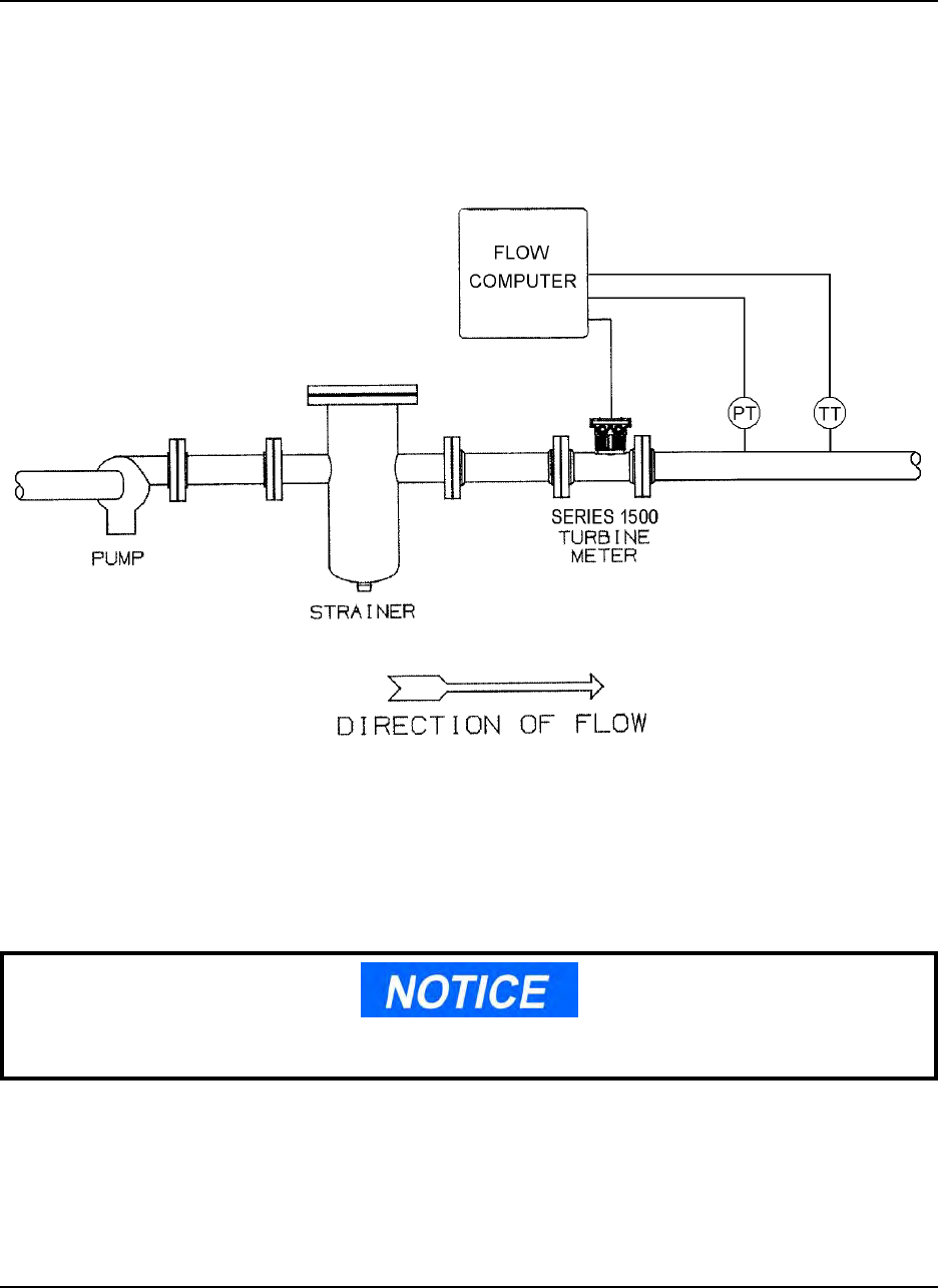
Figure 3-1, Typical Installation, has been provided as a guide in establishing optimum performance
of the meter. Prior to installation, consider the general information listed below.
Figure 3-1. Typical Installation
1. Note the direction of flow indicated on the plate near the inlet flange and install accordingly.
2. New Installations - Lines should be flushed thoroughly to rid piping of potentially damaging
foreign material such as welding bead, pipe scale, etc. before the meter is placed into service.
A spool piece installed in place of the meter is recommended for this procedure.

DANIEL™ SERIES 1500 TURBINE METER OCT 2013
INSTALLATION 3-3
When installing this equipment, bolting must conform to the requirements of ASME B16.5
paragraph 5.3 and to the material requirements of ASME B16.5 Table 1B. Gaskets must conform
to the requirements of ASME B16.20.
It is the customer's responsibility to ensure that piping or other attachments connected to the Product
do not place adverse stresses on the Product.
The design of the Product has not been assessed for the effects of traffic, wind or earthquake
loading.
It is the customer's responsibility to provide fire prevention measures and equipment per local
regulations.
PERSONAL INJURY AND/OR DEATH
Never use equipment for unintended purposes.
Use of this equipment for any purpose other than its intended purpose may result in property
damage and/or serious personal injury or death.
The Product has been designed with a minimum of 1.5mm (.059 inches) corrosion allowance. The
customer should implement a periodic inspection and maintenance program to ensure that no part
of the Product's pressure-retaining components has corrosion or erosion exceeding this amount. (The
design engineer may choose to select a different corrosion allowance, but it should be identified and
published.)

OCT 2013 DANIEL™ SERIES 1500 TURBINE METER
INSTALLATION3-4
MECHANICAL EQUIPMENT DAMAGE
Always use a flushing medium that is compatible with the metallurgy of the meter and
its internal components and similar to the product for which the meter is intended.
Using water as a flushing medium may result in damage to the internal components of the
turbine meter.
A. Valves
The metering system should have a flow rate control valve located at a convenient distance
downstream of all measurement equipment. The function of the control valve is to limit and maintain
system pressure on the meter. This avoids cavitation.
1. Valves should be capable of rapid, smooth opening and closing with positive shut-off.
2. When used for intermittent flow, valves should be fast acting and shock-free.
3. Bypass lines should be equipped with blind or positive shutoff devices.
4. Shut-off or control valves should be located downstream of the meter.
B. Flow Conditioning
For proper operation flow conditioning is required on both the upstream and downstream sides of
the meter.
On the upstream side of the meter a flow conditioning plate can be used (see paragraph C, Flow
Conditioning Plate) or a flow conditioning element designed in accordance with API Ch.5.3. This
element should be installed in an upstream section of pipe having a minimum length equal to 10 pipe
diameters.

DANIEL™ SERIES 1500 TURBINE METER OCT 2013
INSTALLATION 3-5
C. Flow Conditioning Plate
The flow conditioning plate is available for all standard Series 1500 Turbine meters, sizes 3" - 8"
and is designed to eliminate product flow characteristics such as liquid swirl and non-uniform
velocity profiles (induced by piping configurations and other elements of the system) that may
impede proper measurement within the turbine meter run. The plate is installed directly into the inlet
of the meter. Due to the flow conditioning influence on the incoming product, this reduces the
requirement for upstream flow straightening piping. It is recommended that a minimum of five pipe
diameters be maintained upstream and downstream of the meter to assure proper operation. Actual
length will be determined by piping requirements specific to the application.
D. Strainers
A strainer of proper size should be installed upstream of the meter to protect it from the introduction
of foreign material which might damage the meter. Recommended mesh sizes include: 40 mesh for
refined products, and 10 to 20 mesh for crude products (depending on the product being measured).
Strainer Monitoring:
1. Recommended procedures dictate that regular, scheduled cleaning of the strainer basket be
conducted to prevent filling and rupturing of the screen.
2. Pressure gauges installed on both sides of the strainer will indicate differential pressure
across the strainer. High pressure differential caused by filling of the basket or occlusion of
foreign material can cause strainer basket rupture resulting in possible meter damage.

OCT 2013 DANIEL™ SERIES 1500 TURBINE METER
INSTALLATION3-6
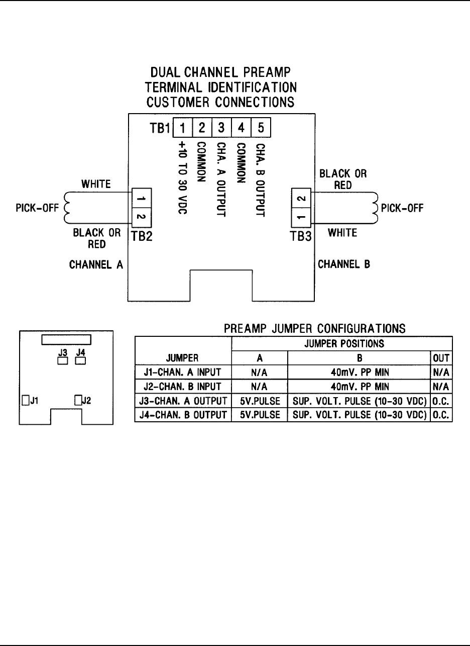
3.4 Pickoff Coils And Electrical Connections
A. Pickoff Coils
The Series 1500 Turbine has the capacity for single or dual pickoff coils mounted 90° electrically
out of phase. Each pickoff produces A low level sine wave signal which varies in amplitude (mV)
and frequency (Hz), proportional to the velocity of the turbine blades. This signal information is
coupled to the input terminals of the preamplifier.
The optional dual UMB Turbine Meter can be configured with up to four pickoff coils, each pair
mounted 90° electrically out of phase.
B. Electrical Connections
Pickoff input signal connections are made at terminal strip connection TB2 for Channel A, and TB,3
for Channel B. Power supply and output signal connections are made at terminal strip TB1.
Reference Figure 3-2. For single channel wiring use Belden 8770, or equivalent. Earth ground shield
at one end only. Terminate shield and insulate it at the other end. For dual channel wiring use Belden
8770, or equivalent for power and channel A signal. Use Belden 8219, or equivalent for channel B.
Connect both shields to earth ground at one end of cables and terminate and insulate shields at the
other end. UMB housing should be at earth ground.
C. Induced Interference
The Turbine meter should be located as far as possible from any electrical equipment such as
motors, solenoids or relays which could induce an interference signal into the turbine meter pickoff
coil. High amplitude interference introduced into the preamplifier can result in interference with the
flow signal.
Proper shielding and an earth grounded UMB housing will greatly reduce the possibility of induced
interference. See Section 3.6 B, Electrical Connections.
D. Accessory Hookup
General considerations: It is important that the appropriate service manual be referenced before
attempting to use accessories or instrumentation with the Series 1500 Turbine. If service manuals
for instrumentation were not received at the time of purchase or delivery, please contact the factory
or nearest Daniel Measurement and Control Sales and Service Office.
DANIEL™ SERIES 1500 TURBINE METER OCT 2013
INSTALLATION 3-7
Figure 3-2. UMB Wiring

OCT 2013 DANIEL™ SERIES 1500 TURBINE METER
INSTALLATION3-8
This page intentionally left blank.

DANIEL™ SERIES 1500 TURBINE METER OCT 2013
OPERATION 4-1
4.0 OPERATION
4.1 General
This section contains the operating procedures for the Series 1500 Turbine Flowmeter. Reference
Section 3-4 for general flow considerations that may effect meter performance. The Series 1500
Turbine Meter is a volumetric flow measuring and transmitting device that produces an output signal
proportional to the rate-of-flow of the liquid being measured. The primary output is a single or dual
high resolution signal that is amplified and shaped by an integral amplifier mounted within an
explosion proof housing. This wave pulse can be fed directly to remote totalizing counters, digital
readout devices or control instrumentation.
4.2 Pre-start Checks
1. Inspect all electrical connections to assure compliance to electrical codes and safety
regulations.
2. All bolts used to secure the meter in line should be inspected to assure that proper mounting
procedures have been followed and that flange connections are leak free.
3. Evaluate the system setup to assure that all components are in the proper sequence for
accurate product measurement: isolation valve, strainer, flow straightener, meter,
downstream section, control valve, etc.
4. Ensure that the supply voltage to the preamp is within the range of 10-30 VDC.

OCT 2013 DANIEL™ SERIES 1500 TURBINE METER
OPERATION4-2
4.3 Operation
Flow and pressure information is stamped on the nameplate located on the outside of the meter.
PERSONAL INJURY AND/OR EQUIPMENT DAMAGE
Never subject the meter to flow or pressure ranges above those specified in Section 2.0
Specifications, or those stamped on the meter.
Exceeding the meter specifications could result in serious injury and/or damage to the
equipment.
1. Back pressure at the outlet of the meter must be sufficient for proper operation. Consider the
following equation when determining back pressure for the meter.
2. Pb = 2 ªp + 1.25 pe
Where
Pb = minimum back pressure, pounds per square inch gauge (psig)
ªp = pressure drop through the meter at the maximum operating flow rate for the
liquid being measured, pounds per square inch (psi)
pe = equilibrium vapor pressure of the liquid at the operating temperature, pounds
per square inch absolute (psia), gauge pressure plus atmospheric pressure
3. Valves should be opened slowly in such a way as to prevent system shock.
4. Care should be taken to protect the Series 1500 housing and components from external
impact of any kind. Note temperature limitations, Section 1 when selecting meter location.

DANIEL™ SERIES 1500 TURBINE METER OCT 2013
MAINTENANCE 5-1
5.0 MAINTENANCE
Reference Figures 7-1 through 7-6 Exploded Parts Drawings.
Item numbers reference actual engineering drawings and are not meant to be consecutively
numbered.
5.1 General
The Series 1500 Turbine is designed to operate for extended periods of time without evidence of
wear or loss of precision. All meter adjustments were completed at the factory during liquid
calibration and should not require field setup. However, should inspection of internal components
be required or should field requirements change, information contained in this document must be
read and understood before attempting any maintenance procedure.
If the Series 1500 Turbine is found to be in need of repair, it is recommended the user contact the
nearest Daniel Measurement and Control Sales or Service Office. It is important that servicing be
performed by trained and qualified service personnel.
5.2 Maintenance Considerations
1. Label all parts or place parts in labeled containers during disassembly.
2. Use no metal clamping devices in direct contact with any meter part or surface.
3. Rotor blades determine proper flow measurement and should be handled with extreme care.
Bending or altering the blades in any way can effect meter accuracy.
OCT 2013 DANIEL™ SERIES 1500 TURBINE METER
MAINTENANCE5-2
5.3 Disassembly Procedures - Internal Components
A. All sizes
1. Before removing the meter from the system the following precautions must be taken:
a. Disconnect all power to the meter.
PERSONAL INJURY AND/OR EQUIPMENT DAMAGE
Disconnect power to the meter.
Failure to disconnect power to the meter could result in serious personal injury and/or damage
to the equipment.
b. Relieve all line pressure.
PERSONAL INJURY AND/OR EQUIPMENT DAMAGE
Relieve pressure at this time.
Failure to relieve line pressure at this time could result in serious personal injury and/or
damage to the equipment.
2. Disconnect conduit connections to the Series 1500 Turbine. (Reference Figure 7-1)
a. Remove screws (item 52) and top cover (item 16) of the UMB.
b. Disconnect conduit connections from terminal board TB1 (assembly item 56).
DANIEL™ SERIES 1500 TURBINE METER OCT 2013
MAINTENANCE 5-3
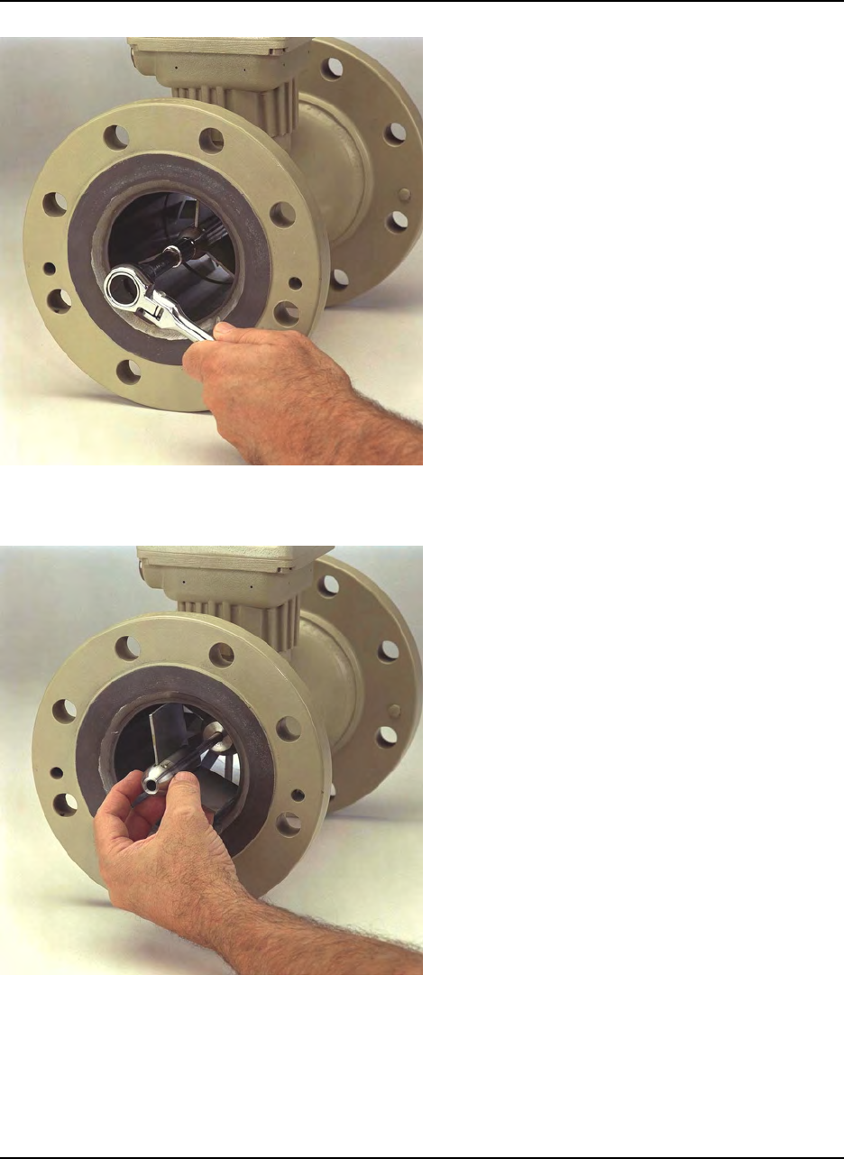
Disassembly Step 1
Remove the downstream shaft nut,
simultaneously holding the upstream shaft
nut to prevent the shaft from turning.
Disassembly Step 2
Remove downstream hanger assembly
from the shaft.
To do this you must withdraw the shaft in
the upstream direction to allow the
insertion of a pin into the hole in the
downstream hanger hub.
Push the shaft back against the pin and tap
the shaft lightly to free the downstream
hanger assembly.
OCT 2013 DANIEL™ SERIES 1500 TURBINE METER
MAINTENANCE5-4
Disassembly Step 3
Remove downstream cone from the shaft.
Thrust washer should remain in cone.
Disassembly Step 4
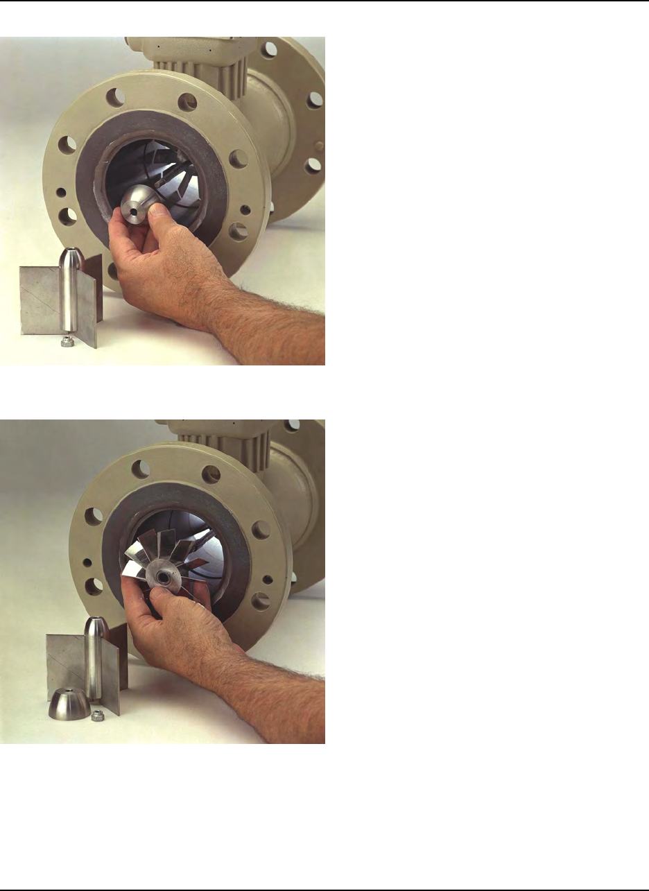
Remove rotor from the shaft. Depending
on the turbine meter option, the rotor
could be just a blade type or a rim type.
The rim is not removable from the rotor
assembly.
DANIEL™ SERIES 1500 TURBINE METER OCT 2013
MAINTENANCE 5-5
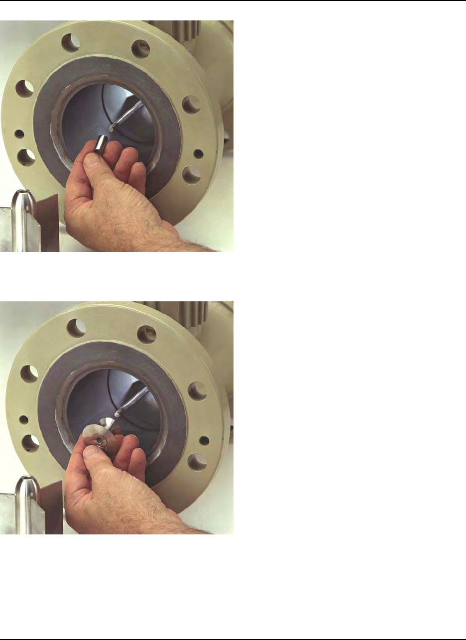
Disassembly Step 5
Remove journal bearing.
Disassembly Step 6
Remove upstream cone from the shaft.
Thrust washer should remain in cone.
OCT 2013 DANIEL™ SERIES 1500 TURBINE METER
MAINTENANCE5-6
Disassembly Step 7
Remove upstream hanger assembly from
the opposite end.
To do this you must insert a pin into the
hole in the upstream hanger hub.
Insert the shaft from the downstream end
and push the shaft against the pin. Tap the
shaft lightly to free the downstream
hanger assembly.
DANIEL™ SERIES 1500 TURBINE METER OCT 2013
MAINTENANCE 5-7
5.4 Reassembly of Internal Components
In all cases reassembly is the reverse of disassembly. Caution must be taken at all times to protect
the rotor blades from rough handling as blade position is critical to meter performance.
POSSIBLE EQUIPMENT DAMAGE
Use torque values in Table 5-1 to reinstall the shaft nut.
Failure to apply correct torque may result in equipment damage or inaccurate meter operation.
Table 5-1. Torque Values for Shaft Nut Installation
Meter Size Torque Requirement
3" 70 in-lbs
4" 100 in-lbs
6" 50-60 ft-lbs
8" 50-60 ft-lbs
10" 60-70 ft-lbs
12" 70-90 ft-lbs
16" 80-100 ft-lbs
18" 80-100 ft-lbs

OCT 2013 DANIEL™ SERIES 1500 TURBINE METER
MAINTENANCE5-8
5.5 Field Retrofitable Dual Pickoff
In the event that a second pickoff is required for equipment originally supplied with a single pickoff,
or should field service or replacement of existing pickoffs be necessary, the following procedure is
recommended.
See Figures 7-1 through 7-6.
1. Disconnect all power to the meter.
PERSONAL INJURY AND/OR EQUIPMENT DAMAGE
Disconnect power to the meter.
Failure to disconnect power to the meter could result in serious injury and/or damage to the
equipment.
2. Remove retaining screws (item 52) and cover (item 16) of the UMB housing assembly.
3. Disconnect terminal connects at TB1, TB2 and TB3.
4. Loosen retaining screws of preamplifier board (item 56) and lift out.
5. Care should be taken not to jar or disrupt terminal board components.
6. Remove screw (item 52).
7. Insert second pickoff (item 11) into the pickoff cavity of the UMB and secure with screw,
(item 52).
2. Mount the preamplifier board in its original position and secure using spring loaded retaining
screws.
3. Attach electrical output wiring from both pickoffs to terminal connection TB2 and TB3 as
shown in Figure 3-2.
4. Attach electrical output wiring from electrical accessories (conduit wiring) to terminal
connection TB1, number 3 for channel A, and number 5 for channel B.
5. Secure all electrical wiring.
6. Return UMB cover and secure using original retaining screws.

DANIEL™ SERIES 1500 TURBINE METER OCT 2013
TROUBLESHOOTING 6-1
6.0 TROUBLESHOOTING
6.1 General
This information has been provided as an aid in basic troubleshooting. Disassembly procedures have
been outlined in Section 5.3 of this manual. If the Series 1500 Turbine is found to be in need of
repair, it is recommended the user contact the nearest Daniel Measurement and Control Sales or
Service Office. It is important that servicing be performed by trained and qualified service
personnel.
Table 6-1. Troubleshooting
Condition Probable Cause Correction
No output pulses from
amplifier module Input voltage to amplifier
below minimum required for
operation
Apply correct voltage (10 -
30 VDC)
Damaged or shorted pickoff
(Resistance across leads
should be 600-900 Ohm)
Replace pickoff
Damaged amplifier module Replace amplifier module
Receiver unit not operating Refer to instruction
manual on defective unit
Meter rotor not turning Troubleshoot internal
assembly
Turbine meter rotor not
turning Defective rotor bearing Return rotor assembly to
factory for replacement or
repair
Rotor damaged by foreign
material passing through
meter
Return rotor assembly to
factory for replacement or
repair
Inaccurate readout Foreign material on rotor
blades Check and clean blades
Rotor blades are bent Return to factory for
replacement or repair
Defective accessory equipment Troubleshoot equipment

OCT 2013 DANIEL™ SERIES 1500 TURBINE METER
TROUBLESHOOTING6-2
This page intentionally left blank.

DANIEL™ SERIES 1500 TURBINE METER OCT 2013
PARTS LIST 7-1
7.0 PARTS LIST
This section contains the necessary parts required to make up any standard unit covered in this
manual. Recommended spare or replacement parts have been denoted by an asterisk.
Item numbers reference actual engineering drawings and are not meant to be consecutively
numbered.
When ordering, the following information must be supplied:
• Serial number
• Part number
• Part description
• Quantity required
OCT 2013 DANIEL™ SERIES 1500 TURBINE METER
PARTS LIST7-2
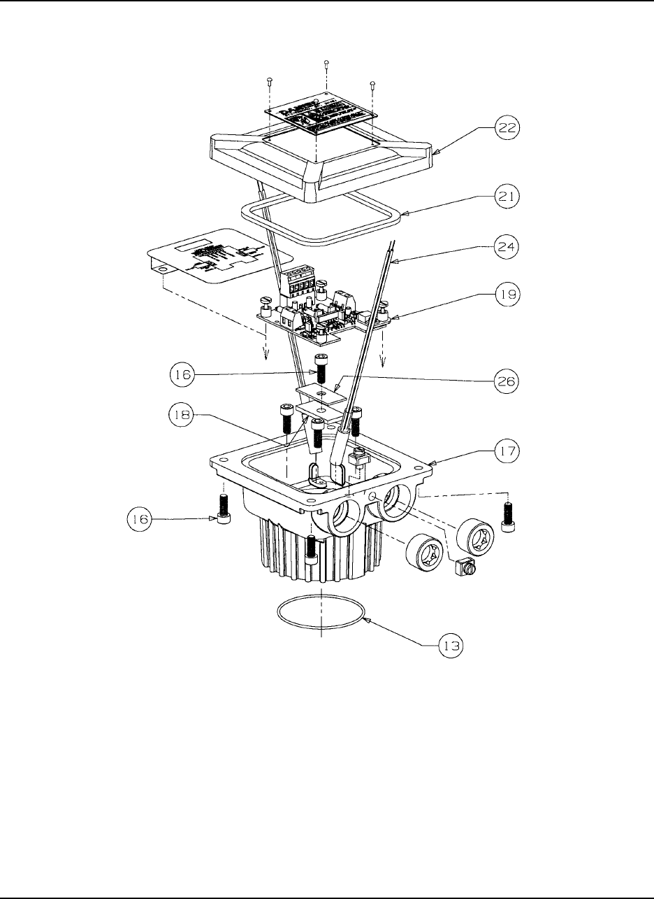
Figure 7-1. UMB Assembly - All Sizes (Reference Table 7-1)
**Torque 55 in. lbs. (16)

DANIEL™ SERIES 1500 TURBINE METER OCT 2013
PARTS LIST 7-3
Table 7-1. UMB Assembly (All Sizes) (Reference Figure 7-1)
Item
Number Description Part Number Quantity
Required
13* O-ring (Viton®-A) 1500093-022 1
16** Screw (Hex Socket Head) 151496 9
17 UMB Housing 899-00-100-00 1
18 Insulator 799-00-424-01 1
19* Dual Channel Preamp 230-00-300-00 1
21* Gasket CA-375Z-259-XXA 1
22 UMB Cover 899-00-101-00 1
24* Pickoff 899-00-201-00 1 or 2
26 Clamp 799-00-424-00 1
* Recommended Spare Parts
** All item 16 - Torque 55 in. lbs., min.
Viton® is a registered trademark of E.I. du Pont de Nemours and Company.
ATEX REPAIR NOTE:
Special Conditions for Safe Use: The joint between the Universal Mounting Box cover and housing
is a flat joint and has a flame path of 9.52mm in length and clearance of less than .0381mm. The
joint between the Universal Mounting Box housing and Sensor housing is a spigot joint which has
a radial length of 3.18mm, a axial length of 13.61mm and a clearance of .059mm.
OCT 2013 DANIEL™ SERIES 1500 TURBINE METER
PARTS LIST7-4
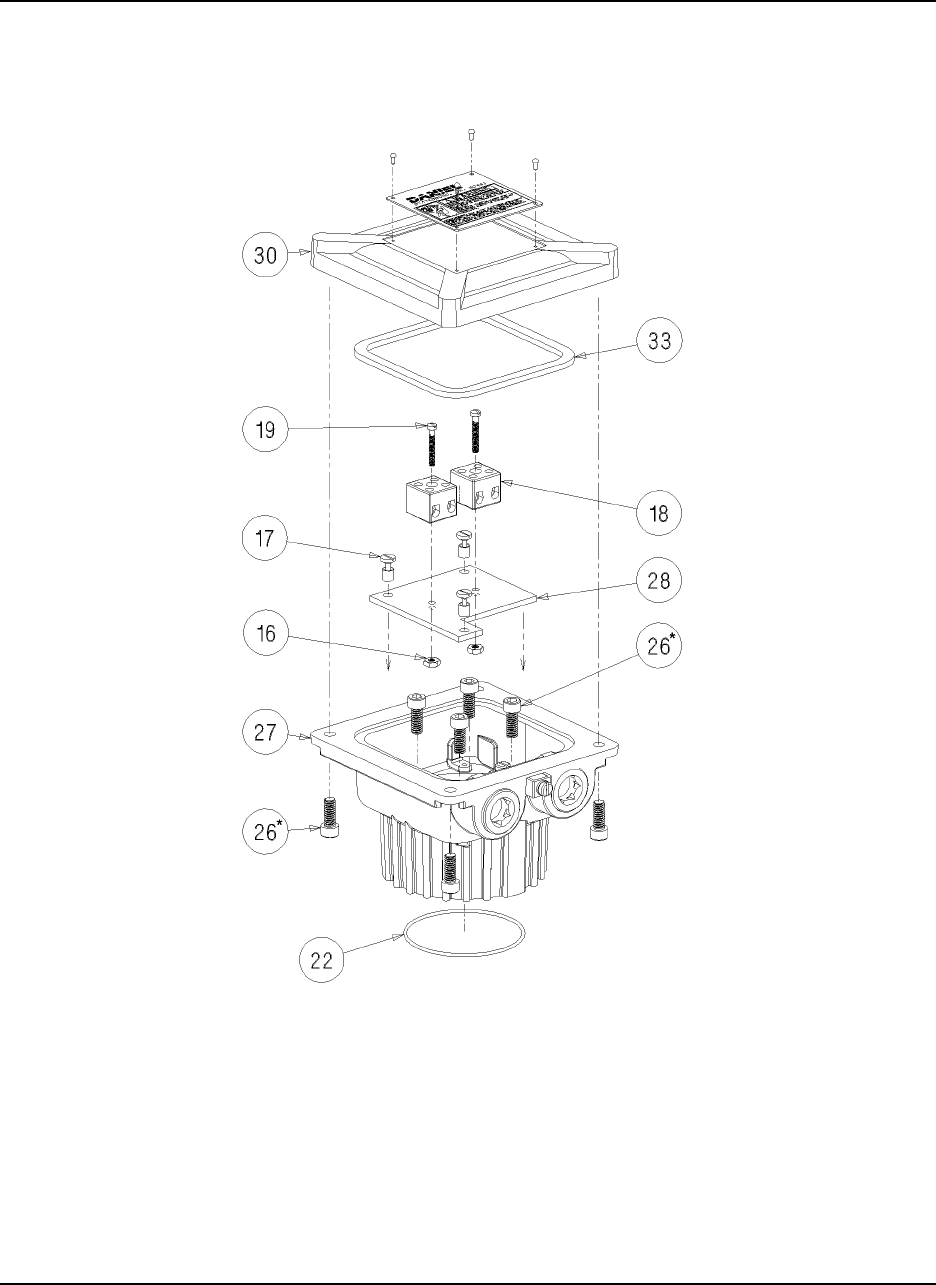
Figure 7-2. High Temperature UMB Assembly (Reference Table 7-2)
* Torque 55 in. lbs. (26)

DANIEL™ SERIES 1500 TURBINE METER OCT 2013
PARTS LIST 7-5
Table 7-2. High Temperature UMB Assembly (Reference Figure 7-2)
Item
Number Description Part Number Quantity
Required
16 Nut 151524 2
17 Mounting screw 1505069 3
18 Terminal block 1505065 2
19 Screw 150511 2
22 O-ring (Viton®-A) 1500093-022 1
26* Screw - hex socket head 151496 8
27 UMB housing 899-00-100-00 1
28 High temp mounting bracket 899-00-600-04 1
30 UMB cover 899-00-101-00 1
33 Gasket CA-375Z-259-XXA 1
* All item 26 - Torque 55 in. lbs., min.
Viton® is a registered trademark of E.I du Pont de Nemours and Company.
ATEX REPAIR NOTE:
Special Conditions for Safe Use: The joint between the Universal Mounting Box cover and housing
is a flat joint and has a flame path of 9.52mm in length and clearance of less than .0381mm. The
joint between the Universal Mounting Box housing and Sensor housing is a spigot joint which has
a radial length of 3.18mm, a axial length of 13.61mm and a clearance of .059mm.
OCT 2013 DANIEL™ SERIES 1500 TURBINE METER
PARTS LIST7-6
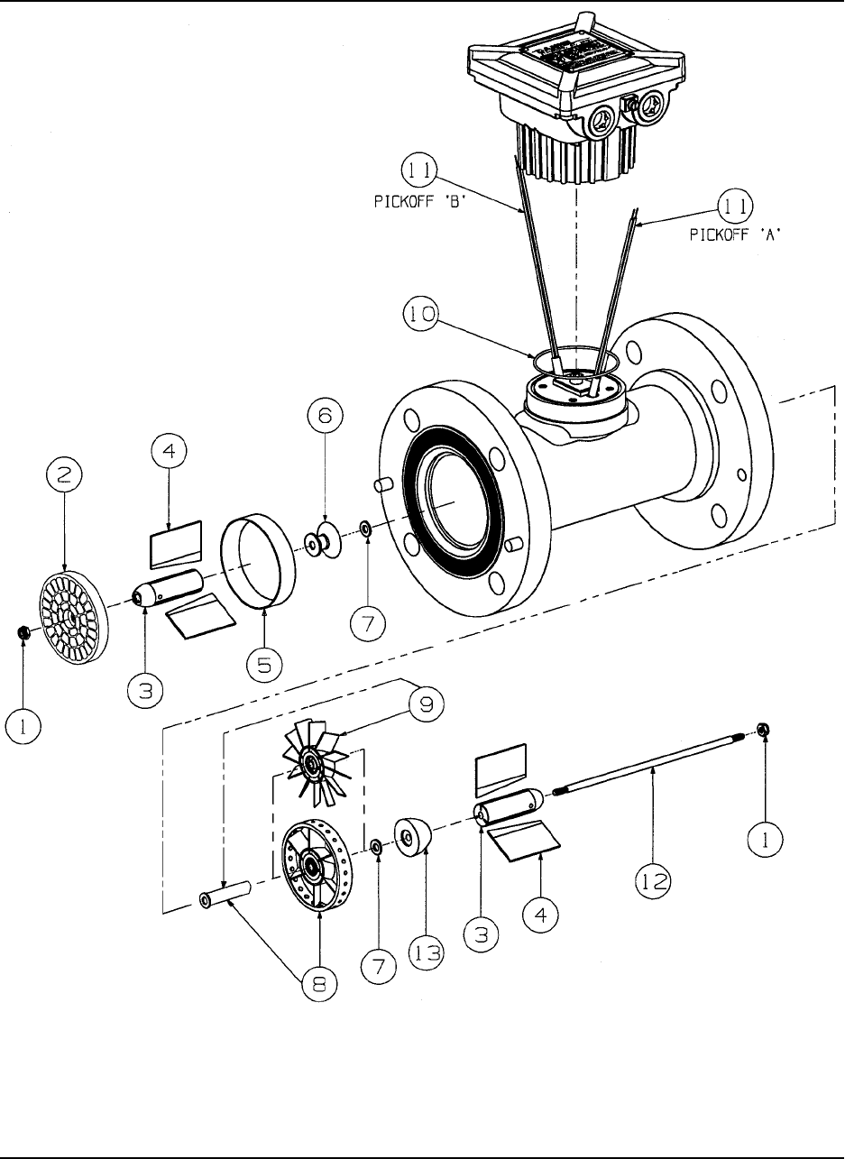
Figure 7-3. 3" through 18" Uni-Directional 1500 Series Turbine (Reference Table 7-3)

DANIEL™ SERIES 1500 TURBINE METER OCT 2013
PARTS LIST 7-7
Table 7-3. 3" through 8"
Uni-Directional Series 1500 Turbine Meter
(Reference Figure 7-3)
Item
No. Description3"4"6"8"
Part No. Qty Part No. Qty Part No. Qty Part No. Qty
1 Nut 1-561-76-192 2 1-561-76-155 2 1-561-76-163 2 1-561-76-171 2
2 Flow conditioning
plate (FCP)
(optional)
1-307-01-171 1 1-307-01-080 1 1-307-01-085 1 N/A N/A
3 Hanger hub 1-307-10-635 2 1-307-10-640 2 1-307-10-645 2 1-307-10-650 2
4 Hanger blades 1-307-10-735 6 1-307-10-740 6 1-307-10-745 6 1-307-10-750 6
5 Housing inserts 1-307-03-000 1 1-307-03-001 1 1-307-03-003 1 1-307-03-004 1
6 Upstream cone -
rimmed 1-307-10-435 1 1-307-10-440 1 1-307-10-445 1 1-307-10-450 1
Upstream cone -
bladed 1-307-10-437 1 1-307-10-442 1 1-307-10-447 1 N/A N/A
7 Thrust washer 1-504-05-114 2 1-504-05-115 2 1-504-05-117 2 1-504-05-118 2
8 Rimmed rotor 1-307-11-237 1 1-307-11-302 1 1-307-11-402 1 1-307-11-404 1
9 Bladed rotor 1-307-11-235 1 1-307-11-300 1 1-307-11-400 1 N/A N/A
10 O-ring 1500093-022 1 1500093-022 1 1500093-022 1 15000093-022 1
11 Pickoff 899-00-201-00 2 899-00-201-00 2 899-00-201-00 2 899-00-201-00 2
12 Shaft 1-504-05-622 1 1-504-05-627 1 1-504-05-632 1 1-504-05-637 1
Shaft for FCP 1-504-05-623 1 1-504-05-628 1 1-504-05-633 1 N/A N/A
13 Downstream cone 1-307-10-535 1 1-307-10-540 1 1-307-10-545 1 1-307-10-550 1
OCT 2013 DANIEL™ SERIES 1500 TURBINE METER
PARTS LIST7-8
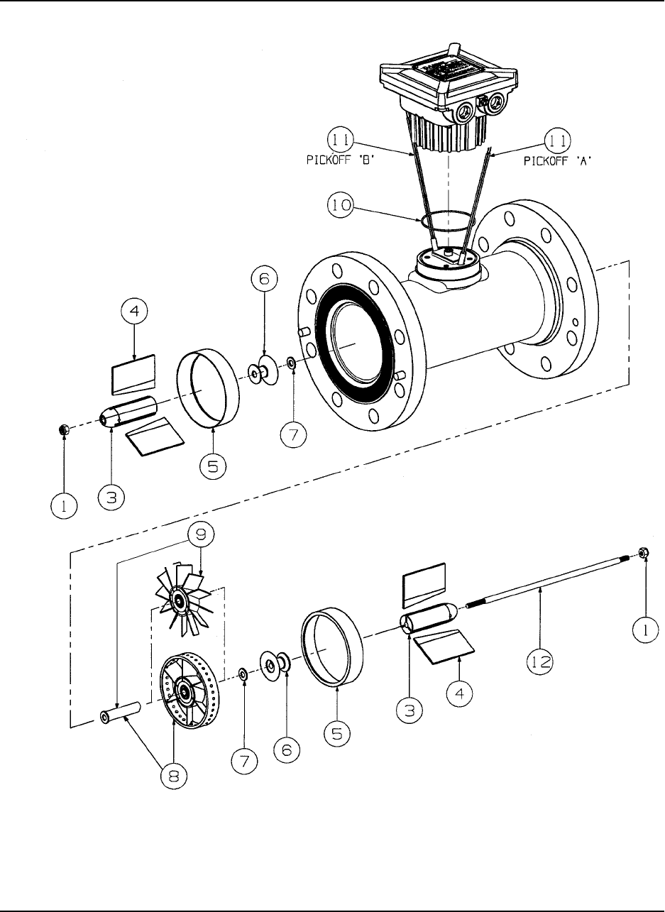
Figure 7-4. 4" through 8" Bi-Directional Series 1500 Series (Reference Table 7-4)

DANIEL™ SERIES 1500 TURBINE METER OCT 2013
PARTS LIST 7-9
Table 7-4. 4" through 8"
Bi-Directional Series 1500 Turbine Meter
(Reference Figure 7-4)
Item
No. Description 4" 6" 8"
Part No. Qty Part No. Qty Part No. Qty
1 Nut 1-561-76-155 2 1-561-76-163 2 1-561-76-171 2
3 Hanger hub 1-307-10-640 2 1-307-10-645 2 1-307-10-650 2
4 Hanger blades 1-307-10-740 6 1-307-10-745 6 1-307-10-750 6
5 Housing inserts 1-307-03-001 2 1-307-03-003 2 1-307-03-004 2
6 Upstream cone - rimmed 1-307-10-440 2 1-307-10-445 2 1-307-10-450 2
Upstream cone - bladed 1-307-10-442 2 1-307-10-447 2 N/A N/A
7 Thrust washer 1-504-05-115 2 1-504-05-117 2 1-504-05-118 2
8 Rimmed rotor 1-307-11-302 1 1-307-11-402 1 1-307-11-404 1
9 Bladed rotor 1-307-11-300 1 1-307-11-400 1 N/A N/A
10 O-ring 1500093-022 1 1500093-022 1 15000093-022 1
11 Pickoff 899-00-201-00 2 899-00-201-00 2 899-00-201-00 2
12 Shaft 1-504-05-627 1 1-504-05-632 1 1-504-05-637 1
OCT 2013 DANIEL™ SERIES 1500 TURBINE METER
PARTS LIST7-10
Figure 7-5. 10" through 12" Uni-Directional Series 1500 Series (Reference Table 7-5)

DANIEL™ SERIES 1500 TURBINE METER OCT 2013
PARTS LIST 7-11
Table 7-5. 10" through 12"
Uni-Directional Series 1500 Turbine Meter
(Reference Figure 7-5)
Item
No. Description 10" 12"
Part No. Qty Part No. Qty
1 Nut 1-561-76-183 2 1-561-76-200 2
3 Hanger hub 1-307-10-655 2 1-307-10-660 2
4 Hanger blade 1-307-10-755 6 1-307-10-760 6
5 Housing insert 1-307-03-005 1 1-307-03-006 1
6 Upstream cone 1-307-10-455 1 1-307-10-460 1
7 Thrust washer 1-504-05-119 2 1-504-05-120 2
8 Rotor assembly 1-307-11-406 1 1-307-11-656 1
9 Downstream cone 1-307-10-555 1 1-307-10-560 1
10 Shaft 1-504-05-642 1 1-504-05-647 1
22 O-ring 1500093-022 1 1500093-022 1
OCT 2013 DANIEL™ SERIES 1500 TURBINE METER
PARTS LIST7-12
Figure 7-6. 16" through 18" Uni-Directional Series 1500 Series (Reference Table 7-6)

DANIEL™ SERIES 1500 TURBINE METER OCT 2013
PARTS LIST 7-13
Table 7-6. 16" through 18"
Uni-Directional Series 1500 Turbine Meter
(Reference Figure 7-6)
Item
No. Description 16" 18"
Part No. Qty Part No. Qty
1 Nut 1-561-76-083 2 1-561-76-088 2
3 Hanger hub 1-307-10-665 1 1-307-10-696 2
4 Hanger blade 1-307-10-765 6 1-307-10-770 6
5 Housing insert 1-307-03-008 1 1-307-03-009 1
6 Upstream cone 1-307-10-465 1 1-307-10-491 1
7 Thrust washer 1-504-05-122 2 1-504-05-123 2
8 Rotor assembly 1-307-11-676 1 1-307-11-686 1
9 Downstream cone 1-307-10-565 1 1-307-10-591 1
10 Shaft 1-504-05-652 1 1-504-05-657 1
11 Cotter pin 1-562-05-639 2 1-562-05-656 2
22 O-ring 1500093-022 1 1500093-022 1

OCT 2013 DANIEL™ SERIES 1500 TURBINE METER
PARTS LIST7-14
This page intentionally left blank.

Daniel Measurement and Control, Inc.
Returned Material Authorization
Repair Form for Used Equipment
Including Decontamination/Cleaning Statement
A Return Material Authorization (RMA) number must be obtained prior to returning any equipment
for any reason. Download the RMA form on the Daniel Measurement and Control, Inc. Support
Services web page by selecting the link below.
http://www2.emersonprocess.com/EN-US/BRANDS/DANIEL/SUPPORT-SERVICES/Pages/Support-
Services.aspx
1. Return Material Authorization (RMA) Number ____________________________________
2. Equipment to be returned:
Model Number _________________________ Serial Number _______________________
3. Reason for return: ___________________________________________________________
___________________________________________________________________________
___________________________________________________________________________
________________________________________________________________________
Decontamination/Cleaning Fluids Process
A. List each substance in which the equipment was exposed. Attach additional documents if necessary.
Common
Name CAS# if
available Used for Hazardous
Waste (20 CFR 261) EPA Waste Code
if used for hazardous waste
[ ] Yes [ ] No
[ ] Yes [ ] No
[ ] Yes [ ] No
[ ] Yes [ ] No
[ ] Yes [ ] No
[ ] Yes [ ] No
B. Circle any hazards and/or process fluid types that apply:
Infectious Radioactive Explosive Pyrophoric Poison Gas
Cyanides Sulfides Corrosive Oxidizer Flammable Poison
Carcinogen Peroxide Reactive-Air Reactive-Water Reactive-Other (list)
Other hazard category (list):
C. Describe decontamination/cleaning process. Include MSDS description for substances used in decontamination and
cleaning processes. Attach additional documents if necessary.

Shipping Requirements
Failure to comply with this procedure will result in the shipment being refused.
1. Write the RMA number on the shipping package.
2. Inside the package include one copy of this document and all required Material Safety Data
Sheets (MSDS)
3. Outside of the package attach one copy of this document and all required Material Safety Data
Sheets (MSDS).
THIS EQUIPMENT, BEING RETURNED “FOR REPAIR,” HAS BEEN COMPLETELY
DECONTAMINATED AND CLEANED. ALL FOREIGN SUBSTANCES HAVE BEEN
DOCUMENTED ABOVE AND MSDS SHEETS ARE ATTACHED.
By:
(Signature) (Print name)
Title: Date:
Company:
Phone: Fax:
NOTES
NOTES

Emerson Process Management
Daniel Measurement and Control, Inc.
11100 Brittmoore Park Drive
Houston, TX 77041
T+1 713-467-6000
F+1 713-827-4805
www.emerson.com
Copyright© 2013
Daniel Measurement and Control, Inc. and Daniel Measurement Services, Inc. Divisions of Emerson Process Management reserve the right
to make changes to any of its products or services at any time without prior notification in order to improve that product or service and to
supply the best product or service possible.
Daniel Measurement Services, Inc. offers both on-call and contract maintenance service designed to provide single-source responsibility
for all Daniel products. The sales and service offices of Daniel Measurement and Control, Inc. are located throughout the United States and
in major countries overseas. For the location of the sales or service office nearest you, telephone the number below or visit the Daniel
Measurement and Control, Inc. website.
T+1713-827-6314
F+1713-827-4805
www.emerson.com
