Emerson Type 289Rc Exhaust Booster Data Sheet
2015-03-30
: Emerson Emerson-Type-289Rc-Exhaust-Booster-Data-Sheet-681389 emerson-type-289rc-exhaust-booster-data-sheet-681389 emerson pdf
Open the PDF directly: View PDF ![]() .
.
Page Count: 4
Bulletin 71.8:289RC
July 2010
D103080X012
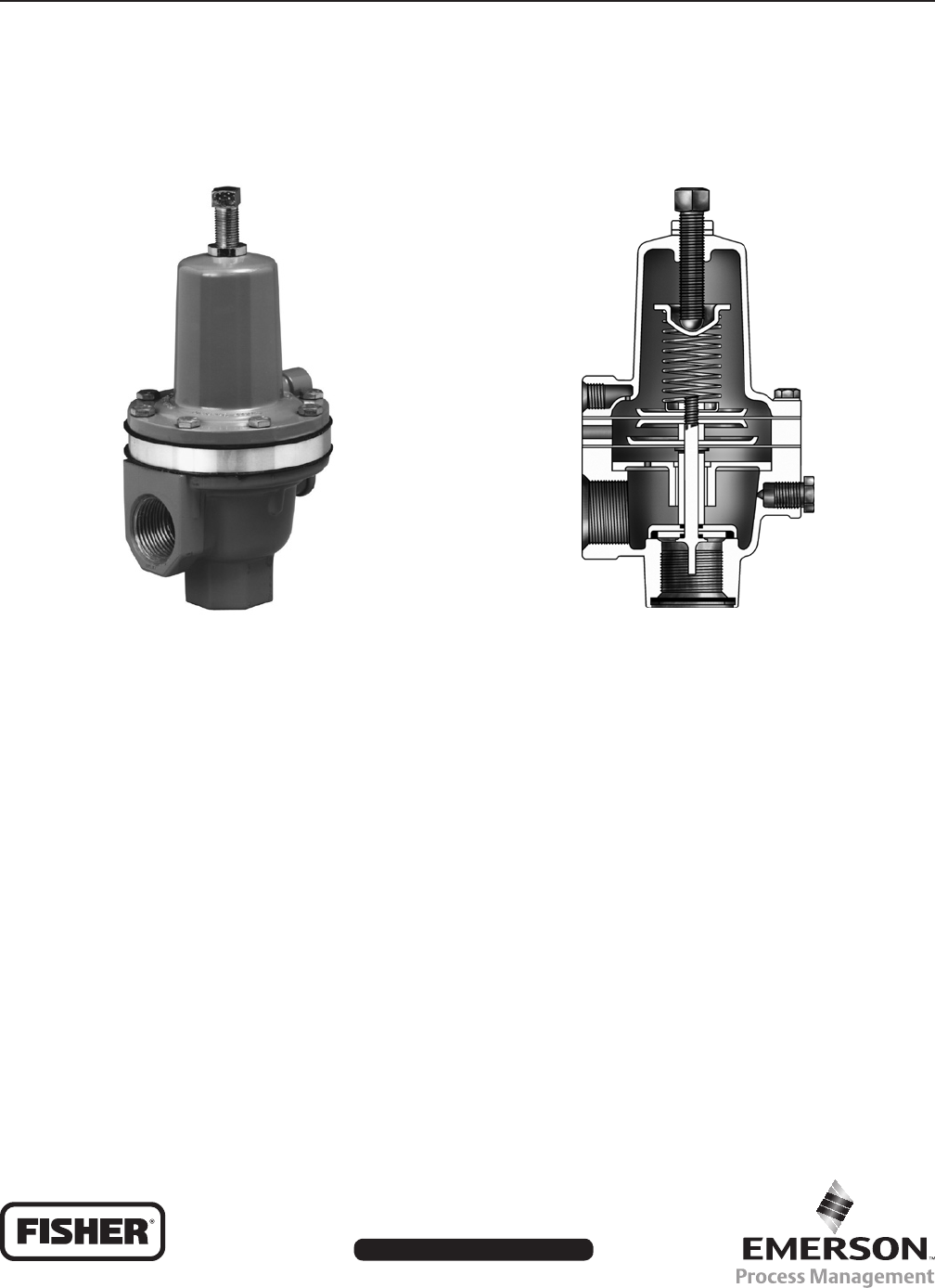
The Type 289RC is a high-capacity, throttling exhaust
booster designed to provide throttling “release control”
(RC) control pressure to actuators, pneumatic devices,
and related systems that require rapid response
(i.e. surge valves or recycle valves on compressors).
These exhaust boosters are normally used on control
valve actuators to speed up the proportional operation
of a control valve in response to sudden pressure
changes from pneumatic output devices such as
solenoid valves or pneumatic instruments. The
one way throttling action offers superior control with
exceptional stability.
—By accurately matching the
instrument and actuator performance with the
bypass valve adjustment, the Type 289RC reduces
overshoot and related problems while allowing very
fast positioning response to system requirements.
—The boosting system allows the
Type 289RC to provide high ow rates with
minimum pressure buildup.
—The smooth,
sensitive throttling action minimizes pressure
surges caused by system uctuations.
Figure 1. Type 289 Throttling Exhaust Booster Figure 2. Type 289 Throttling Exhaust Booster Sectional View
W7313 W7322
Bulletin 71.8:289RC
2
(1)
1 NPT
Connect to the outlet via a bypass valve,
adjustable from 0 to 0.3 Cv. (Piping is normally
congured by the customer.) See Figure 3.
1/8 NPT
1 NPT
(1)
125 psig (8,6 bar)
Fixed at 1 to 1
Bypass valve closed, less than 10% of
the control pressure
Bypass valve open, variable from
0 to 10% of the control pressure
C
v = 22. System capacity limited by the
smallest restriction between the exhaust valve
and pressure source
(1)
-20° to 180°F (-29° to 82°C)
4 pounds (2 kg)
1. The pressure/temperature limits in this Bulletin and any applicable standard or code limitation should not be exceeded.
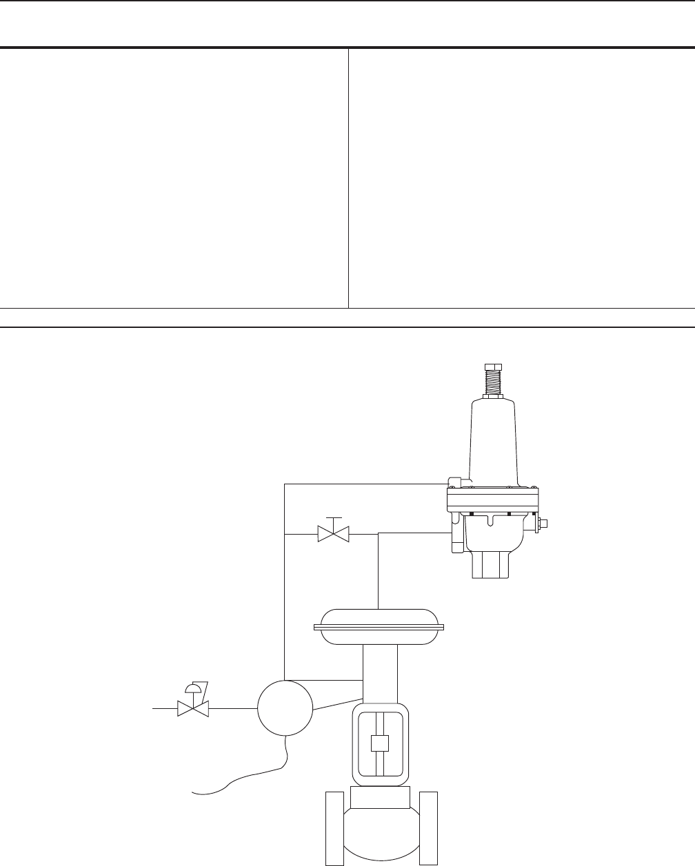
Figure 3. Typical Type 289RC Throttling Exhaust Booster and Control Valve Installation
A7208
)
A
Bulletin 71.8:289RC
3
The instrument connection must be made to the spring
case, 1/8 NPT tting. The actuator is connected to
the 1 NPT side port. The inlet and outlet must be
connected via an adjustable bypass valve. Flow
through the exhaust valve must be as indicated by the
ow direction arrow on the body. See Figure 3.
The Type 289RC 1 NPT output port is connected
directly to a spring return actuator and the 1/8 NPT
inlet port is connected to the controlling instrument
(I/P transducer, positioner, controller, etc.). The inlet
and outlet chambers connected through a needle
valve. The needle valve is adjusted on the control valve
system to account for differences in various instrument
and actuator performance characteristics.
Once this adjustment has been accomplished the
control valve action is described as follows: As the
output pressure of the instrument increases the
actuator moves the valve normally since the exhaust
booster cannot be actuated in this manner. When
the output pressure of the instrument decreases the
actuator will move the valve normally until the rate of
change of the output pressure exceeds the capacity
limit of the needle valve. When this occurs, the
pressure drop in the Type 289RC causes the booster
exhaust valve to open and quickly drop the pressure
in the actuator. Because of the throttling action of
the Type 289RC, the booster exhaust valve closes
as the pressure difference between the instrument
and actuator decreases and the control valve system
resumes normal operation.
Refer to the Specications section on page 2. Carefully
review the description below each specication to
be sure exhaust booster meets the needs of the
application. Specify the product type number to your
local Sales Ofce.
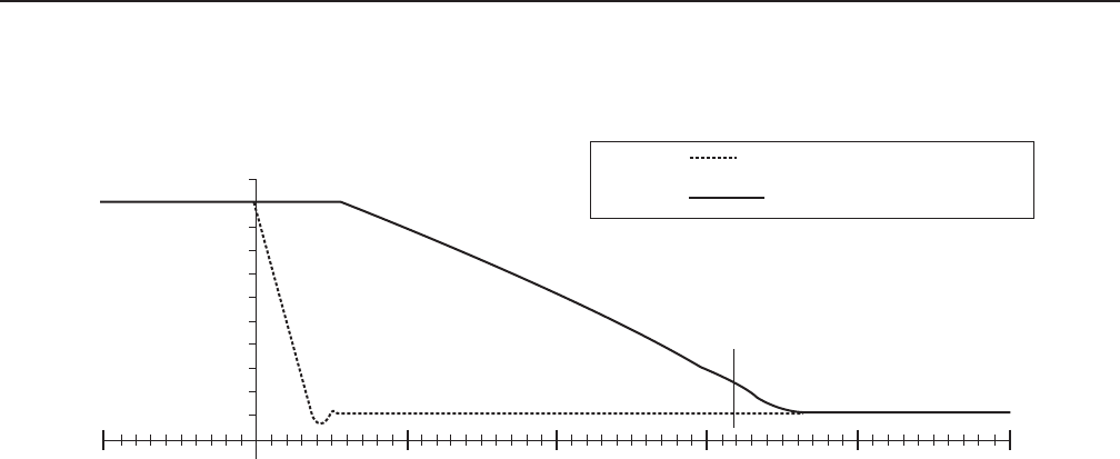
Figure 4. Typical Response Curve for Type 657 size 45 Actuator with Type 289RC Throttling Exhaust Booster
110
70
50
40
10
A7218

Bulletin 71.8:289RC
The Emerson logo is a trademark and service mark of Emerson Electric Co. All other marks are the property of their prospective owners. Fisher is a mark owned by Fisher Controls, Inc., a
business of Emerson Process Management.
The contents of this publication are presented for informational purposes only, and while every effort has been made to ensure their accuracy, they are not to be construed as warranties or
guarantees, express or implied, regarding the products or services described herein or their use or applicability. We reserve the right to modify or improve the designs or specications of such
products at any time without notice.
Emerson Process Management does not assume responsibility for the selection, use or maintenance of any product. Responsibility for proper selection, use and maintenance of any Emerson
Process Management product remains solely with the purchaser.
©Emerson Process Management Regulator Technologies, Inc., 2003, 2010; All Rights Reserved
USA - Headquarters
McKinney, Texas 75069-1872 USA
Tel: 1-800-558-5853
Outside U.S. 1-972-548-3574
Asia-Pacic
Shanghai, China 201206
Tel: +86 21 2892 9000
Europe
Bologna, Italy 40013
Tel: +39 051 4190611
Middle East and Africa
Dubai, United Arab Emirates
Tel: +971 4811 8100
USA - Headquarters
McKinney, Texas 75069-1872 USA
Tel: 1-800-558-5853
Outside U.S. 1-972-548-3574
Asia-Pacic
Singapore, Singapore 128461
Tel: +65 6777 8211
Europe
Bologna, Italy 40013
Tel: +39 051 4190611
Gallardon, France 28320
Tel: +33 (0)2 37 33 47 00
USA - Headquarters
Elk River, Minnesota 55330-2445 USA
Tel: 1-763-241-3238
Europe
Selmsdorf, Germany 23923
Tel: +49 (0) 38823 31 0
For further information visit www.sherregulators.com
