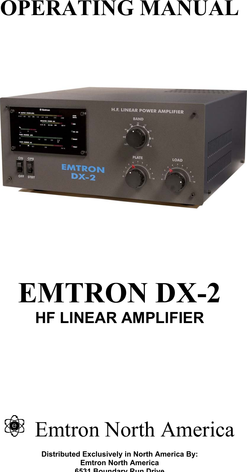
Emtron North America DX-2 HF Amature User Manual 308274

Emtron North America HF Amature 308274

Users Manual

OPERATING MANUAL            EMTRON DX-2 HF LINEAR AMPLIFIER        Emtron North America  Distributed Exclusively in North America By: Emtron North America 6531 Boundary Run Drive
DX-2,   Serial No…………    INITIAL SETTINGS FOR PLATE AND LOAD CAPACITORS  TEST  FREQUENCY BAND FACTORY SETTINGS 50 OHM LOAD USER SETTING ANTENNA   PLATE LOAD  PLATE  LOAD 21.200 MHz  15m         18.100 MHz  17m         14.200 MHz  20m                   7.070 MHz  40m          3.600 MHz  80m          1.800MHz  160m          1.850 MHz  160m          1.900 MHz  160m             TABLE 1
TABLE OF CONTENTS  1 GENERAL DESCRIPTION.................................................................................................................................1 1.1 DX-2 – INTERNAL VIEW.............................................................................................................................2 2 TECHNICAL SPECIFICATIONS ......................................................................................................................3 3 UNPACKING.........................................................................................................................................................3 3.1 OPENING THE CARTON................................................................................................................................4 3.2 OPENING THE DX-2 COVER ........................................................................................................................4 4 INSTALLATION I ENVIRONMENT.................................................................................................................4 4.1 REQUIRED ENVIRONMENT ..........................................................................................................................4 4.2 POWER REQUIREMENTS ..............................................................................................................................4 5 REAR PANEL ....................................................................................................................................................... 4 5.1 POWER / EARTH CONNECTIONS...................................................................................................................4 5.2 RF CONNECTIONS .......................................................................................................................................4 5.3 TRANSCEIVER CONTROL .............................................................................................................................4 6 FRONT PANEL.....................................................................................................................................................5 6.1 CONTROLS..................................................................................................................................................5 6.2 DISPLAYS ...................................................................................................................................................5 7 ELECTRICAL CONNECTIONS ........................................................................................................................6 7.1 CONNECTIONS TO TRANSCEIVER / EXCITER ...............................................................................................6 7.2 EARTH AND MAINS CONNECTIONS ..............................................................................................................6 7.3 TERMINATING THE POWER CABLE (EXPORT VERSION) ................................................................................7 7.4 OPERATION AT 230V, 220V AND 200V (EXPORT VERSION)........................................................................7 8 DX-2 DESCRIPTION............................................................................................................................................7 8.1 RF SECTION................................................................................................................................................7 8.2 MAINS TRANSFORMER ................................................................................................................................8 8.3 H. V. POWER SUPPLY .................................................................................................................................8 8.4 SOFT START MODULE.................................................................................................................................. 8 8.5 SENSOR MODULE ........................................................................................................................................8 8.6 ANTENNA RELAY / QSK MODULE...............................................................................................................8 8.7 DISPLAY BOARD .........................................................................................................................................8 8.8 CONTROLLER BOARD..................................................................................................................................8 9 POWERING UP ....................................................................................................................................................9 10 OPERATION .........................................................................................................................................................9 10.1 TUNNING PROCEDURE - ......................................................................................................................9 10.1.1 General........................................................................................................................................................9 10.1.2 Preliminary tuning ......................................................................................................................................9 10.1.3 Final tuning............................................................................................................................................... 10 10.1.4 Potential problems during tuning..............................................................................................................10 10.2 ALC ADJUSTMENT ..............................................................................................................................10 10.3 USING YOUR DX-2 ...............................................................................................................................11 10.3.1 CW / RTTY and all digital modes..............................................................................................................11 10.3.2 Voice modes (SSB) ....................................................................................................................................11 10.3.3 Hints on good linearity and efficiency.......................................................................................................11 11 SWITCHING THE POWER OFF .....................................................................................................................11 12 TROUBLESHOOTING - IF SOMETHING GOES WRONG ........................................................................ 12 12.1 NO POWER ................................................................................................................................................12 12.2 FAN GOES TO HIGH SPEED ......................................................................................................................... 12 12.3 FAN NOT WORKING ...................................................................................................................................12 12.4 IF THE FAULT LIGHT TURNS ON...............................................................................................................12 12.5 OVER-TEMPERATURE CUT-OFF .................................................................................................................12 12.6 OVER-CURRENT CUT-OFF .........................................................................................................................12 12.7 IG2 BLINKS FAST - NO PLATE VOLTAGE ....................................................................................................12 12.8SPARKS/DISCHARGES INRFAREA..........................................................................................................13
14 GLOSSARY .........................................................................................................................................................13 15 SERVICE .............................................................................................................................................................14 15.1 GENERAL..................................................................................................................................................14 15.1.1 CONTROL BOARD................................................................................................................................... 14 15.1.2 DISPLAY BOARD ADJUSTMENTS .........................................................................................................18 15.1.3 RF SENSOR ADJUSTMENT..................................................................................................................... 19 16 DIAGRAMS AND SCHEMATICS....................................................................................................................21 16.1 DX-2 BLOCK DIAGRAM ...........................................................................................................................21 16.2 CONTROL BOARD CONNECTIONS AND ADJUSTMENT POINTS ...................................................................22 16.3 DISPLAY BOARD ADJUSTMENT POINTS .................................................................................................... 23 16.4 CIRCUIT DIAGRAM – HIGH VOLTAGE POWER SUPPLY ....................................................................24 16.5 CIRCUIT DIAGRAM – AC INPUT AND SOFT START WIRING – U.S. VERSION .....................................25 16.6 CIRCUIT DIAGRAM – RF MODULE .........................................................................................................26 16.7 CIRCUIT DIAGRAM – DISPLAY BOARD ................................................................................................27 16.8 CIRCUIT DIAGRAM – SOFT START – 240 VOLT VERSION....................................................................... 28 16.9 CIRCUIT DIAGRAM – QSK........................................................................................................................29 16.10 CIRCUIT DIAGRAM – CONTROL BOARD ..............................................................................................30 16.11 CONTROL BOARD – COMPONENT LEGEND ...............................................................................................31 16.12 CONTROL BOARD – SOLDER SIDE TRACK WORK ......................................................................................32
DX-2 LINEAR AMPLIFIER Serial No ………… OPERATING MANUAL January 2003 CAUTION               1 GENERAL DESCRIPTION The Emtron DX-2 Linear Amplifier is a 1500 watt carrier output power, for the 160m through 15m amateur bands (7 bands), housed in a desk-top cabinet with self-contained power supply and cooling system. It utilises a single high performance tetrode, type GU84B (4CX2500),  a ceramic metal tube with a plate dissipation of 2500W. The tube is air cooled by a commercial grade forced air turbine blower system with 2 speeds, controlled by a temperature sensor. Tetrodes offer exceptionally stable operation and levels of quality performance far exceeding that which can be expected from triodes. The harmonic output and intermodulation distortion achieved with this tube are exceptionally low. This is especially important when dealing with a high output power.  The Emtron DX-2 is supplied as standard with a host of features including solid state metering, comprehensive protection systems and extremely long duty cycle. In addition, a unique Emtron QSK module is available as an option. With this installed, extremely rapid switching times between transmit and receive are possible, with consequent advantages when using the digital modes. Operation of the DX-2 is greatly simplified by the absence of meter switching, mechanical displays and front panel level setting controls. The front panel moving LED display systems indicate plate voltage, plate current, output power, reflected power, screen grid current, ready, overdrive warning, and high SWR cut-off indication.  The Emtron Electronic Bias Switch (EBS) automatically switches the standing current (typically 0.37 A) off when there is no modulation. This reduces the average tube dissipation. On initial switch on, the unique Emtron "soft start" circuitry ensures that no damaging AC surge currents are generated.  Professional, fine output tuning adjustment is possible, due to the 6: 1 reduction mechanism fitted.       The DX-2 has been designed for 100% safe operation and long life. Interlocking sensing circuitry constantly monitors conditions inside the amplifier. It must be noted however, that the high voltages present inside the DX-2 are EXTREMELY DANGEROUS. Do not remove the top cover under any circumstances if any leads are still plugged into the rear of the amplifier - especially if the AC lead is plugged in the power outlet. Before any component inside the high voltage, power supply or output section is touched, unplug all rear panel leads and allow at least 5 minutes of 'off time'. After that, you should further check this by momentarily shorting the tube anode to the chassis with a suitable insulated lead.
1.1  DX-2 – Internal View The main components of a DX-2 amplifier are shown in the picture below.
 3  2 TECHNICAL SPECIFICATIONS  FREQUENCY COVERAGE: Complete (manually tuned) coverage of the seven HF amateur bands:    1.800 –  1.900 MHz  3.500 –  4.000 MHz  7.000 –  7.500 MHz 14.000 – 14.350 MHz 18.000 – 18.500 MHz 21.000 – 21.500 MHz   TRANSMITTING MODES: Both continuous and low duty cycle modes are supported. That is, the DX-2 supports SSB, CW, AM, FM, RTTY and SSTV. OUTPUT POWER: Typical 1500 watts PEP  DRIVE POWER: Nominal 50-60 watts for full rated output.  INPUT IMPEDANCE: Nominal 50 ohm passive impedance, unbalanced. VSWR 1.4:1 or less.  OUTPUT IMPEDANCE: Tuned circuit, nominal 50 ohm load, VSWR maximum 2.6:1 set by protection circuit. DISTORTION: Third order intermodulation products are more than 35 dB below rated output.  HARMONICS: Harmonic output is better than 47dB below the rated output.  FAULT PROTECTION: The extremely comprehensive fault protection systems include circuitry to monitor:  • plate current: should the plate current exceed a safe value, the amplifier goes to standby mode for 2 minutes.  • screen grid over-current: Absolute tube protection is offered with visual warning and a reduced power level being enabled if the screen current exceeds a pre-set limit.  • temperature: Should the tube's temperature exceed a specific level, amplifier operation is suspended until the temperature drops to a safe level. OPERATIONAL PROTECTION  • Overdrive protection: Should the DX-2 be overdriven, a LED warning indictor will light up when the linearity limit is reached. If the drive is increased further, a 2 second cut off (by-pass) will follow.  • SWR protection: Should the DX-2 sense a load impedance with SWR exceeding 2.6:1, an LED warning indicator will light up, simultaneously with a 3 second cut off (by-pass).  METERING: The front panel moving LED display systems indicate:  • plate voltage • plate current • output power  • reflected power  • screen grid current  • ready and fault conditions • overdrive warning  • SWR cut-off indicator    ALC: Negative going, adjustable output level. EBS: Electronic Bias Switch - automatically switches the standing current (about 0.37 A) to a lower ("pre-bias") value - when there is no input drive. PRE-BIAS: A small current will flow in the tube when the amplifier is keyed on, but there is no modulation. This will prevent a harsh sound at the beginning of each word, when the EBS is activated and the tube goes through a non-linear zone, before reaching the correct initial bias.  QSK: is an option that makes possible the antenna switching at very fast rate - typically 3ms switching time in each direction. FACTORY INSTALLED ONLY.  SOFT START: when switched on, the mains power is gradually applied to the transformer, over a period of about 5 seconds, to avoid the high in-rush current typical for such high loads (transformer “Bang” and filament over-current). COOLING: the cooling fan has 2 speeds, with electronic temperature control. Most of the time the fan runs at low speed, for reduced noise.  OPERATING TEMPERATURE: 0 to 40° Celsius  FUSING: Two 20A fast acting fuses on the rear panel  DIMENSIONS: 435mm wide, 190mm high, 465mm deep WEIGHT: 4lkg (90 lb) unpacked   3 UNPACKING  The DX-2 is packed in a heavy duty package easily sufficient to protect the amplifier during transportation, even in case of fairly rough handling. The weight of the commercially rated mains transformer does mean, however, that dropping the amplifier would without doubt result in some damage.
 43.1  Opening the carton  Save the packing material for possible further re-use. Shipment of your DX -2 in other than factory packing may result in non-warranty damage.   3.2  Opening the DX-2 cover  An inspection of the interior of the amplifier should reveal no damage or adversely affected components. Remove the 4 screws on each side and remove the cover. Should there be any form of problem, notify your supplier immediately.   4 INSTALLATION I ENVIRONMENT  4.1 Required environment  The DX-2 amplifier can be operated at an ambient temperature between 0 and 40° Celsius. It should be installed in a place with a good ventilation and protected from the direct sunlight. At least 5 cm (2 inches) of free space must be left at the rear and left and right, for ventilation. Do not place any object on top of the amplifier, especially above the ventilation opening.  An environment free of dust, smoke and high humidity is required, as for any high powered RF amplifier. Dust, or particles resulting from burning fire wood or coal could be responsible for sparks or electrical discharges between the capacitor plates, or in other parts of the RF section.  4.2 Power requirements  When operating at full power, up to 16A from the 240 VAC mains is required. Ensure that the AC supply you intend to use is fully rated and properly fused. The Emtron "soft start" circuitry ensures that there are no momentary surges of current at power-up, therefore the fuse does not need to be over-rated. However, the wiring of the mains supply for the amplifier should be able to handle the power at full load with minimal drop in the voltage, to insure the performance of your DX-2 does not suffer. 5 REAR PANEL The following connectors and controls are present on the rear panel 5.1  Power / Earth connections A wing-nut Earth connection is provided at the rear of DX-2. A good Earth link must be provided here. Connect this first, before making any other connection to the amplifier. The AC power input is protected by two 20A fuses.  5.2 RF connections  RF INPUT The RF input is an SO-239 female connector. A 50 ohm coaxial cable line of good quality terminated with a PL-259 coaxial connector is required to connect the transceiver or exciter output to the input connector of your DX-2 amplifier.  RF OUTPUT  The RF output is also a female SO-239 connector. The use of a high quality RG-8A/U, RG-213 or similar 50 ohm coaxial cable line terminated with a ‘VHF’ type PL-259 connector is essential. Similarly, a VSWR of 2: 1 or better is  mandatory. Remember too, that the EMTRON DX-2 amplifier can deliver 1.5 kW continuously in the SSB mode. Not all antennas can handle such power.  5.3 Transceiver control  ALC  The ALC output is via a black female RCA connector.  This is an ALC system for use with transceivers or transmitters having a negative-going ALC system and possessing an external ALC input jack. A shielded patch lead with an appropriate connector at one end and a male RCA connector for the DX-2 at the other end is required. Check the specifications of your transceiver for a suitable connection.  PTT  The PTT input is a female RCA connector (red). This line controls the transmit/receive switching system. This jack must be connected to transceiver or exciter relay contacts which are open on RECEIVE and closed on TRANSMIT. In the standard version (DX-2 fitted with a l2V antenna relay), the PTT input presents an open circuit voltage of  + l2V with respect to the chassis, with an impedance of about 70 ohm. Therefore, a current of typically 0.17 A must be switched by the transceiver or exciter.  In the QSK version, the voltage at the PTT input is typically 28V (and up to 36V unloaded), with an impedance of about 240 ohm. A current of  about 0.12 A has to be switched in this case.   ALC CONTROL  This is a user-accessible control for setting the negative voltage at the ALC output. Further details are given in section 10.2
 5 6  FRONT PANEL  The following controls and indicators are present on the front panel: 6.1 Controls  BAND SWITCH  A nine position switch selects the desired frequency range. The 7 operating bands are indicated in metres. The last two switch positions are not used in the U.S. version of DX-2. If a special licence is produced, the amplifier can be delivered with all 9 bands operational. PLATE TUNE  Tunes the amplifier operating frequency. A chart of approximate starting settings is given in Table-1  LOAD TUNE  Tunes the amplifier output loading. A chart of approximate starting settings is given in Table-1  ON/OFF  Switches the AC power on and off. On initial switch on, the standby mode is enabled. Note also the appropriate switch down sequence, given in Section 11.  OPR/STBY Enables the amplifier once it has warmed up. In STANDBY mode, the screen voltage is removed and any RF power applied to the input, is bypassed to the output. If this switch is changed to OPERATE before the READY light comes on, the FAULT light will turn on. This is not a fault, but it is better to leave the switch in STBY position until the amplifier is ready to operate.  6.2 Displays All the DX-2 indicators are concentrated in a single, solid state, "moving LEDs" display (See drawing). The following parameters are displayed (top to bottom):  Output Power - Scale up to 2kW. Yellow LEDs, with red indicating power over 1.5kW.  Reflected Power - Scale up to 250W. The colour is green, yellow and red, indicating progressively higher reflected power and possibly problems with your antenna.   Ig2 - Zero-centred display. The left (green) side has a full scale of about 25 mA of negative screen current. The right (red) side has a full scale of about 50 mA of positive screen current. Above this value, the red LEDs will flash, warning you to increase the loading, or reduce the drive. At about 60 mA, the protective current limiting will cut in.   Plate Voltage - Scale up to 3.3kV, green.   Plate Current - Scale up to 2.0A. Yellow, with a green zone indicating the standing current bias (when EBS is disabled only. NOTE: the factory adjustment could be slightly different from the green zone indication). The area above 1.8A is red. It indicates excessive plate current, due to high drive level and improper tuning (especially plate tuning - see "Tuning" chapter, Section 10.1).  ON Air - single LED, green. When pressing PTT, this LED turns on (while in OPERATE)   READY - single LED, yellow. Turns on at the end of warm-up period, when the mains power to DX-2 is switched on. It turns off for about 2 minutes if the plate current protection is triggered. In this case, the FAULT light also turns on (if switch on OPR).  FAULT - single LED, red. Turns on in 3 situations:    when the over-temperature protection is triggered, the FAULT turns on until the tube cools to a safe level. During this time, the operation of the amplifier is disabled, the screen voltage is off and any RF power applied to the input is bypassed directly to the output.   when the over-current protection is triggered, FAULT turns on for 2 minutes, while READY turns off   at DX-2 power up, if the OPR/STBY switch on the front panel is left in OPR position. The FAULT light will go off when the DX-2 is ready for operation, after warm-up.    SWR - single LED, red. A three second cut-off will happen if your antenna has a SWR worse than 2:1 (typical 2.6:1) at the operating frequency. During the cut-off, the RF from the input is directly by-passed to the output.   OVER-DRIVE - single LED, yellow. Flashes when the input drive is exceeding the linear operation level. If even more drive is applied, the overdrive protection will cut off (by-pass) the operation for about 2 seconds.
 6                       Figure 1.   DX-2   Front Panel Display  7 ELECTRICAL CONNECTIONS  7.1  Connections to Transceiver / Exciter  Signal connections Before making any connections, ensure that DX-2 is not connected to AC power, and the transceiver is not  transmitting. Connect the antenna first to the DX-2 output. Then connect the transceiver output to the DX-2 RF input. Plug the PTT lead into the RCA socket marked PTT on the rear panel. If required, connect the ALC.  The most appropriate interconnection layout is shown in Figure 1 below. In this set-up, the transmit/receive relays in the DX-2 are controlled directly by the transceiver or exciter.                        Figure 2.   Connections between DX-2 and station transceiver    7.2  Earth and mains connections  Power connections Before connecting any power to the amplifier, make a good Earth connection to the screw with wing nut at the rear of DX-2. Make sure the POWER switch on the front panel is in the OFF position. Then plug the power cable into the power point.  RF OUTPUT POWER (kW)REFLECTED POWER (W)PLATE VOLTAGE (kV) PLATE CURRENT (A) Ig2 OVER DRIVE ON AIR READY SWR FAULT EMTRON DX-2 STATION TRANSCEIVER RF IN  RF OUT TO ANTENNA ALC  ALC PTT  Relay Input PTT  Relay Output
 77.3  Terminating the power cable (export version)  As different countries have different standards for their power connections, all DX-2 amplifiers exported from Australia are supplied with un-terminated power cables. The green/yellow wire is connected to the amplifier chassis and MUST be connected to the safety ground of the AC mains supply. It must NEVER be connected to one of the AC 'hot' wires. The brown and blue wires connect to the mains transformer input. The brown wire is the "active", or "live". The blue wire is the mains neutral. Both wires are fused.  7.4  Operation at 230V, 220V and 200V (export version)  The Emtron DX-2 will normally arrive pre-set for the power source of the country the amplifier has been sold to. However if operation to another mains voltage is required, the appropriate connection changes will be needed.  Figure 2 shows the transformer connections for 200V, 220V, 230V and 240V operation. If a change is required, this should be done only by a qualified technician, after taking all the necessary safety precautions. See CAUTION on page 1. PLEASE NOTE: The DX-2 should not be connected to a mains supply of less than 200V AC !                                 Figure 3.   DX-2   Transformer AC Input Connections    8 DX-2 DESCRIPTION 8.1  RF Section  The RF section occupies the right hand side of the DX-2 (looking from the top - front). See picture in 1.1.   RF Switch and tuned circuits   At the front of the amplifier are two variable capacitors, for plate and load tuning and a band switch. Next to the switch is the “Pi” coil. The “L” coil is wound on a ferrite torroid.  RF Sub-chassis   The GU84B tube is positioned on a separate RF sub-chassis. All the connections to the tube, except for the plate, are under this sub-chassis. A 9-way heavy duty connector is used for inter-connections. The fan blows air into this sub-chassis, which is forced out through the ventilation fins of the tube. The air temperature is sensed by two sensors placed above the tube. The sensors must stay in a position close to horizontal. Make sure you are not pushing them down, too close to the tube, as high voltage exists between them. The plate is connected to the RF network and to the choke supplying the 2500VDC voltage to the plate of the GU84B tube.  0 0 0 0 240 230220200FANFANFANFAN240240240230230230220220220200200200240 volt: 230 volt: 220 volt: 200 volt:
 88.2 Mains transformer  The transformer is the heart of the amplifier, a high performance type, designed to reduce the size and weight. It is built with a generous reserve of power, handling easily the DX-2 requirements in continuous operation. The primary can be wired for 200VAC, 220VAC, 230VAC or 240VAC operation. See Figure 2. There are several secondary windings, as follows:   Filament supply  Low voltage supply to the controller board  QSK module supply   Bias supply  Screen grid supply   High voltage supply  8.3  H. V. Power Supply A full wave bridge rectifier and filter converts the high voltage AC into high voltage DC with a huge reserve capacity of 58 microfarads. 8.4  Soft start module  At power up, the mains power is gradually applied to the transformer by the soft start module. The power is gradually applied over a time of about 5 seconds, avoiding the high inrush current typical for such big loads.  8.5 Sensor module  A small metal box positioned at the output of the DX-2. It detects the forward and reverse power, for measurement and display, as well as for SWR monitoring and to activate the protection, when needed. 8.6  Antenna relay / QSK module In the standard DX-2, the antenna relay is controlled by the transceiver, via the control board. It switches the antenna between the transceiver, during reception, and amplifier, during transmission. It is also used to bypass the RF from the transceiver, directly into the antenna, when the amplifier is in standby mode, or during special conditions like overdrive, bad SWR or other error conditions.  When the QSK option is installed, this is a module with two very fast, high power vacuum relays, and the control circuitry. The purpose of QSK is to allow very fast switching between transmit and receive, during digital communications. See Annex 1 showing oscilloscope displays of fast switching times and contact bounce-free operation of the QSK module.    8.7 Display board This board has a number of inputs where various voltages are connected. The board converts these voltages into a "moving LED" type of display. Two of these displays have flashing light indication (Ig2 and plate current).   8.8 Controller board  The brain of the amplifier is the Controller Board. The following circuitry is part of this board:   Bias voltage regulator, also incorporating a sensitive grid current detector for overdrive detection . Adjustable pre-bias, removes the distortion at the beginning of the word, when EBS is activated.   Screen voltage regulator, with adjustable voltage and adjustable current limiting, for tube protection.   Overdrive protection and timer - based on detecting grid current, it initially gives visual warning and, at higher level of overdrive, it cuts off the amplifier for 2 seconds.    It ensures a clean signal, making it virtually impossible to overdrive the DX-2  SWR detector and timer - switches the amplifier to bypass mode for about 3 seconds when high SWR is detected. Adjustable SWR level. Factory adjusted to about 2.6: 1   EBS - the Electronic Bias Switch - senses the presence of RF input power and turns on the bias to start transmission. Factory adjusted for about 0.5W. When the input power exceeds this limit, the plate current starts flowing. When there is no speech, even for a very short time, the tube dissipation is cut to a low value, as set by the pre-bias adjustment.  Interlocking, timer for filament warm-up  Relay control: ready relay, SWR relay, over-drive relay, antenna relay  QSK switching control  Display control: Ig2 measurement and display, SWR cut-off display, overdrive warning display, READY display, FAULT display  Logic circuitry, low voltage supply to the various electronic circuits
 99 POWERING UP Before switching the power on, check all the necessary connections: Earth, Antenna, Transceiver, PTT, ALC (if used). Make sure the 2 switches on the front panel are in the positions: OFF, STBY.  Switch now the mains power ON (The power switch to ON position). The "soft start" system will take about 5 seconds to fully turn the power on. After 5 seconds, the display will indicate the plate voltage, typically 2450 V. The FAULT light will turn on briefly, then off. Wait for the DX-2 to warm up, until the READY light turns on.  This takes about 2 - 3 minutes. This is a minimum required. If you are not in a hurry, give it another minute or two before transmitting.     WARNING! WHEN YOU SWITCH THE POWER ON, YOU MUST HEAR AIR FLOW NOISE. IF THERE IS NO AIR FLOW NOISE, SWITCH THE POWER OFF IMMEDIATELY AND CONTACT YOUR SUPPLIER   10 OPERATION  10.1  TUNNING PROCEDURE -  10.1.1 General For each band and operating frequency, the transceiver settings must match the position of the BAND switch on the front panel of the DX-2, while the PLATE and LOAD knobs must be adjusted for optimum operation which gives – in conjunction with the input drive level, the maximum output power that can be obtained for that input power. When the tuning is correct, this will also result in a minimum plate current, minimum plate dissipation and good linearity.  10.1.2 Preliminary tuning  • Turn the BAND switch to the same band setting as the transceiver. (Also, make sure the right antenna is used). • Put LOAD and PLATE knobs in the initial positions given in Table 1.  • DX-2 must be powered ON and "Ready", with the OPR/STBY switch in OPR position.  • Start with the transmitter at minimum power, in a "carrier" mode e.g. RTTY or CW - key down.  • Key the transceiver ON and gradually apply power to the DX-2. When 0.5 to l W of drive is reached, the EBS is activated and the plate current jumps from zero to about 0.3 - 0.4A  • Increase the drive until there is some output power indicated. If the current plate Ip reaches about l A and there is still no output indication, turn PTT off and check the connections, the band and the initial settings.  • As soon as there is any power indication, tune PLATE for maximum output (and minimum plate current).  • Apply more drive and adjust PLATE again for maximum output. Keep PTT ON for short time only (about 10 seconds). Go gradually, in several steps. When about 700 - 1000W output is reached, adjust LOAD for maximum output. If there is no red Ig2 indication, it is likely that LOAD needs to be turned clockwise, towards higher numbers on the dial.  • Apply more drive and adjust both knobs again. When screen current appears (red Ig2 indication), increase loading by turning anti-clockwise the loading capacitor. (LOAD towards lower numbers on dial) until Ig2 drops almost to zero. Then adjust PLATE for maximum output power and maximum Ig2. At this point, Ig2 is the most sensitive indicator of resonance on the working frequency. If Ig2 goes too high (e.g. starts blinking), increase the loading again, then tune PLATE.  • Repeat the above steps, while gradually increasing the input drive power, until the overdrive indicator just starts turning on. Now the DX-2 is tuned for operation at full power on that particular operating frequency.  NOTES:  1. The maximum power is obtained from a DX-2 when:  onset of the overdrive indication  PLATE is tuned for maximum output power, maximum screen current Ig2 and minimum plate current, Ip  Ig2 indicator shows 2 or 3 red LEDs.  2. The above conditions will also give the best linearity.  3. During the preliminary tuning, switch PTT on and off several times, to allow time for tube cooling. The tube dissipation (at a given drive level) is minimum when tuning is optimum. In short, be brief, with tuning "bursts".  4. Preliminary tuning, as described above, is only necessary when operating for the first time in a certain band. When the final settings for PLATE and LOAD have been found for the particular working conditions -  especially the antenna used, note your settings on Table 1. The new settings will normally differ to some extent from the ones indicated, depending on the "purity" of your antenna load. Note that the settings (especially LOAD) will be different at lower output power – See “Tuning for less than full power”.
 1010.1.3 Final tuning  Once the preliminary tuning has been done for each band / antenna combination, the values found for PLATE and LOAD can be used for final tuning, with no need to repeat the preliminary tuning every time.  Tuning for full power • Start with low drive level and the PLATE and LOAD knobs in the known initial positions  • Put PTT ON and increase the power (fairly quickly), to the onset of the overdrive indication. If the screen current (red Ig2) goes too high, adjust LOAD, by turning the knob to the left (increasing the load).  • Adjust the drive level and LOAD until the overdrive indicator is just about to turn ON, and at the same time Ig2 shows two or three red LED's ON.  • Fine tune PLATE for maximum output and maximum Ig2.  • Repeat the last two steps above if required.  Tuning for less than full power  • Start at low power, with the initial values for PLATE and LOAD • Put PTT ON and apply drive until the output is about 1/2 of the desired power.  • Adjust LOAD for maximum output. Most likely, the knob will have to be rotated to the right, towards higher numbers on the dial.  • Adjust PLATE for maximum output  • Apply more power  • Repeat the 3 steps above until the required power is achieved. If screen current is indicated by Ig2, is should, display two or three red LED's. Maximise this Ig2 indication (and the output power at the same time), by tuning PLATE • If the output goes higher then desired, reduce the drive and re-tune. Never reduce the output by de-tuning the amplifier!   NOTE: If the output is low (say, less than about 700W), Ig2 will never show any screen current at all. Ig2 might even indicate a negative current, in green - this is normal and is no cause for concern). However, if there (green) negative current indication, usually this will go away with better tuning of the PLATE control. If there is no Ig2 red indication., simply rotate LOAD to the right in small steps, and each time maximise the output by turning PLATE, until the highest possible maximum in the output power is achieved.   10.1.4 Potential problems during tuning  The tuning operation. should be completed fairly quickly. If the tuning process takes a longer time, it should be done by switching the transmission on and off several times, to allow the tube time to cool. • If the fan changes to high speed, the operation can continue, as there is ample reserve of cooling power. However, it is the best to make a pause (about 1 minute will be sufficient) and wait for the tube to cool. • If the FAULT light comes on, it is possible that the plate current has reached too high values due to incorrect plate tuning. In this case, reduce the excitation power, wait for the FAULT light to turn off (about 2 minutes) and resume tuning.  • If the overdrive protection is activated, by cutting off the amplifier for 2 seconds. It is likely in this case that you are applying too much power at the input. Reduce the power and watch the "overdrive" LED. Increase the power only until this light starts flashing. • If the SWR protection cuts in - it is likely that your antenna is not a good 50 ohm match at the operating frequency. In principle, the SWR protection level in DX-2 is adjustable, but it is far preferable for you to fix your antenna.  10.2  ALC ADJUSTMENT  The DX-2 can be operated without any ALC connection. However, if you wish to use it, and your transceiver has an ALC input, then the potentiometer on the rear panel must be adjusted. This adjustment is not critical, since its voltage output is zero under normal operation and it increases sharply (towards a negative value - up to -11 V), when the overdrive limit is approached. The ALC in DX-2 amplifier is not a conventional design, this circuit operates for only one reason - to prevent overdriving and to keep the signal clean. To adjust the ALC potentiometer: • Turn the potentiometer initially all the way to the right (minimum ALC voltage) • In CW mode, after tuning, apply increasingly higher drive, until the "overdrive" LED just starts to turn on • Increase the drive slightly more, to have the light fully on, but make sure the DX-2 overdrive protection does not cut you off. At this power level, adjust the ALC potentiometer to the left, until the transceiver drops its power output.  Alternatively, in voice mode, increase the RF gain or the microphone gain until the overdrive led is flashing at peak of modulation. Then, increase ALC (rotate potentiometer to the left) until the transceiver begins to limit the drive to DX-2.  NOTE: Some types of transceivers (e.g. YAESU FTI00MP, FT920 and others) are not compatible with this type of ALC. They require an ALC signal proportional with the output power. DX-2' s ALC is zero until the drive reaches the over-drive limit, when the negative voltage increases sharply. YAESU operating manual indicates that this type of ALC might not work well with their transceivers, since grid current could be generated by amplifier mis-tuning not related to excessive drive conditions. If this is the case, simply do not connect it.
 1110.3  USING YOUR DX-2  While tuning and adjusting the amplifier, a CW mode is normally used. When these operations are finished, you can change to the operating mode you wish to use and start operating.  10.3.1 CW / RTTY and all digital modes  In CW, the setting up of the amplifier is similar to that of the tuning mode. After adjusting the input power level to the amplifier, according to the desired output level, and tuning the plate and load capacitors, you can simply start operating by applying the same carrier level as during tuning. If the amplifier is set to deliver full output power, or close to, then screen current will be present. As in the case of tuning, the best operation is achieved when there is a certain amount of screen current flowing, corresponding to two or three red LED's turning on in the Ig2 display. 10.3.2 Voice modes (SSB)  When a voice modulation is applied to the amplifier, the drive level is not precisely defined, as in the case of tuning with continuous carrier. If there is screen current flowing, or an input overdrive, they will be indicated only at peak of modulation, by the respective indicators flashing. You will have to adjust the microphone gain, or the RF drive, or both, in an attempt to achieve input driving conditions similar to those you have used while tuning. Occasional flashing of the overdrive indicator is acceptable. If the over-driving is severe, a momentary cut-off will occur.  10.3.3 Hints on good linearity and efficiency Operating with good efficiency: If you are watching the plate current indicator, you must be aware that the total power the amplifier is drawing from the mains is proportional to the plate current. Power that is not sent to antenna, is dissipated by the tube. As explained in the Tuning section, the best tuning achieves a maximum power output at the same time with a minimum plate current, drastically minimising the tube dissipation. Be aware that at a low power level, slightly different tuning is required than is for full power.   Achieving the best linearity: The amplifier must be tuned and operated all the time in the linear mode. This is important because a non-linear operation will generate harmonics which will disturb RF communications in other bands and frequencies.  We must distinguish two situations:  Less than full power. With less then full power (say 1000W or less), correct tuning, no screen current and no input overdrive indication, you will always have your DX-2 operating with a good linearity and clean signal.  Full power operation.   At full power, there are two things that must be watched to see when you reach the limit of linear operation: the screen current, Ig2, and the grid current, indicated by the "Over-drive" LED.  In this case a good linearity is maintained up to the moment when the screen current is approaching the full scale value of the Ig2 indicator and it starts flashing, or when the overdrive indicator begins to turn on.  A high screen current, indicated by 4 LED's on in the Ig2 display, will create a moderate level of distortion.  Even a small amount of grid current will cause severe distortion. When the "Over-drive" indicator just begins to turn on, there is already a small amount of distortion, created by a grid current of about 100 microamperes.   With this indicator flashing, you are at the limit of the RF carrier clipping. This is probably more acceptable in a voice mode of operation. In CW or digital modes, the best is to slightly reduce the drive, just below this level. A severe level of over-driving is not possible anyway, due to the cut-off protection. The cut-off will happen at about 400 microamperes of grid current.  See the Appendix 2 and the Troubleshooting section for oscilloscope displays showing examples of a two tone generator driving the DX-2 in linear mode, and an overdrive situation, when a DX-2 with the overdrive protection disabled is being overdriven by the two-tone generator.   The Ig2 indicator should have two to four LED's flashing on at peak of modulation. This (combined with a correct plate tuning), indicates an optimum loading, good efficiency and good linearity. A lower screen current, due to excessive loading, will reduce the output power, with an equal amount of extra power dissipated by the tube. A higher screen current, making all four LED's in the Ig2 flashing, will increase the distortion.  11  SWITCHING THE POWER OFF When you have finished using the amplifier and you want to switch it off, the following procedure is recommended:  Stop transmitting.  Put the switch on STBY.  Leave the DX-2 running idle for a few minutes, to cool the tube, then switch the power off.
 1212  TROUBLESHOOTING - If something goes wrong  12.1  No power  • When you switch on a DX-2, it takes about 3 - 5 seconds for the lights on the front panel display to come on. This is due to the "soft start" circuit. If nothing happens after turning the power on, switch off at the front panel, then check  the following:  • make sure the power outlet has power  • make sure the power plug is fully pushed in into the power outlet.  If it is still not working, unplug the power cord from the mains, then remove the fuses from the fuse holders on the rear panel of DX-2 and check them with an ohmmeter.  • If a fuse is blown, replace it with a fuse of the same type and try again.  • If the fuse blows again, or if the fuses were not blown in the first place, contact your supplier.  12.2  Fan goes to high speed  This could happen especially during tuning, or when the ambient temperature is high. It could also happen when the ventilation is restricted, for example by blocking the openings at the back, sides or on the top of the amplifier. In normal operation, with correct tuning, the DX-2 should be able to handle the maximum power with the fan still running at low speed. Usually driving the amplifier with high power and bad tuning can make the fan to go high speed. When this happens, the tube temperature is nominally 120° Celsius. This offers a margin of 30°C before a temperature cut-off occurs, and way below the tube rating, of 200°C. That means you can continue to operate the amplifier with the fan at high speed, but the best is to let it idle until the fan drops back to low speed. This usually takes less than one minute.  12.3  Fan not working  As soon as you switch the power on, you should notice two things about your DX-2: the display should indicate about 2500V of plate voltage, and you should be able to hear the fan running. The amplifier is not supposed to be powered without the fan, even in idling mode. If the fan does not operate when you power up, or if it stops while using the amplifier, switch the mains power off immediately and contact your supplier.   12.4  If the FAULT light turns on The FAULT (red) light turns on in two situations:   • Over-current in the plate circuit  This could happen due to a flash-over in the tube, or as a result of a momentary high plate current during tuning. This completely disables the amplifier for about 2 minutes. The same timer is activated as when the amplifier is switched on, causing the READY light to turn off. If the OPR/STBY switch on the front panel is put on STBY, the FAULT will turn off, but the READY will be also off. When the READY comes on again, the FAULT will disappear (if the amplifier was left in OPR), and the DX-2 is ready to operate again. • Over-temperature cut-off. See below.  12.5  Over-temperature cut-off  This would normally happen after a change of the fan to high speed. The operation of the amplifier is disabled, but the timer is not activated. The FAULT light turns on.. When the tube cools down, the FAULT turns off and the operation can resume. This type of fault should never happen. DX-2 has a very efficient air cooling system. When the ventilation is not restricted, in normal ambient conditions, when properly tuned, a DX-2 can operate at full power for extended periods of time, with the fan not even going to high speed. The temperature cut-off happens when the tube reaches 150º Celsius, with ample safety margin to the specified limit of 200ºC for the GU84B tube.  12.6 Over-current cut-off  If the plate current exceeds even for a brief time a pre-set safe limit, an over-current detector will activate the power up timer, disabling the amplifier for about 2 minutes. During this time the READY light is off, and the FAULT light is on, if the amplifier is left in OPR mode, as explained under 12.4, "If the FAULT light turns on".  12.7  Ig2 blinks fast - No plate voltage  If the high voltage is lost due to a fault in the amplifier, the screen current tends to reach very high values. This is an unlikely situation, but if did happen, this would normally guarantee a tube failure in unprotected amplifiers that do not have a current limiting circuit. The screen current limiting in DX-2 is so efficient, that the tube is fully protected even in such a situation and test bench DX-2's have been extensively run with no plate voltage and maximum screen voltage, with no effect on the tube. If this loss of high voltage should happen to your DX-2, the Ig2 display will have the red LEDs flashing, due to the screen current exceeding the pre-set limit, with no input power applied to the amplifier, while switched to OPR.  In such a case, it is possible that the high voltage is still shown on the display, but it does not reach the tube. In any case, this is a major fault. Put the amplifier on STBY and the flashing will stop. Then switch the power off and contact your supplier.
 1312.8  Sparks / Discharges in RF area  Very high RF voltages are present in the amplifier during the operation at high power. Incursion of dust or even suicidal insects can cause such temporary problems.  12.9  SWR cut-off  The factory adjustment for SWR protection is about 2.6: 1. This adjustment can be changed, but the best is to operate with a properly matched antenna. Should your DX-2 'see' bad SWR, it will shut down for 3 seconds (in bypass mode).  12.10  Frequent over-drive protection cut-off  As previously described in the tuning and operation sections, there is a protection acting on DX-2 input overdrive. When the drive reaches the limit where signal distortion begins to occur, the overdrive indicator on the front panel will warn you to reduce the drive. If you increase the drive even further, a cut-off protection is activated.  After about 2 seconds of amplifier bypass, the operation is resumed, but if you have not reduced the drive, the  protection will be activated again. To stop it, you must reduce the input power drive. This protection is not adjustable, you must not exceed the limit. If this happens too often, you obviously do not have a fine control over the transmit level of your transceiver. In this case, try using the ALC, See section 10.2. 12.11  Tube replacement  It is very unlikely that you will ever need to replace the GU84B. If there is a need for that, the tube is easy to replace, but a bias adjustment is required for the new tube. See the service section of this manual. 13 WARRANTY I SERVICE The full FOUR YEARS warranty for DX-2 amplifiers covers all parts and labour, except for the tube. The tube is under a limited warranty, also for FOUR YEARS.   14 GLOSSARY  AC     Alternating Current ALC     Automatic Level Control  AM     Amplitude Modulation CW     Continuous Wave  DC     Direct Current EBS     Electronic Bias Switch FM     Frequency Modulation  HF     High Frequency  LED     Light Emitting Diode PEP     Peak Envelope Power RF     Radio Frequency  RTTY     Radio Tele Type SSB     Single Side Band SSTV     Slow Scan Tele Vision SWR     Standing Wave Ratio VAC     Volts, Alternating Current VDC     Volts, Direct Current  WARC    World Administrative Radio-communications Conference VSWR     Voltage Standing Wave Ratio
 1415 SERVICE  15.1 General All Emtron amplifiers are built in a modular for. Most modules are common for the entire DX-n range. This makes it easier to service the amplifier. However, this should only be attempted by suitable qualified people, with proper tools and test equipment. Apart from the damaged that could be caused to the amplifier by unqualified intervention, the high voltages and high RF power present in these amplifiers makes them extremely dangerous. Extreme care is recommended event to those very experienced in this area.  The following pages describe the main adjustments required on the DX-2 linear amplifier.  15.1.1 CONTROL BOARD  This procedure refers to adjustments made to the board already installed in the amplifier. This would be required, for example, after replacing the tube or after certain repairs. After a tube replacement only one or two adjustments are required: BIAS and (if EBS used): PRE-BIAS  15.1.1.1  PRE-BIAS ADJUSTMENT (Adjustment: POT7, marked PRE_BIAS) The pre-bias is required when the Electronic Bias Switching (EBS) is used. If the EBS link is kept in OFF position, the pre-bias does not need to be adjusted. PRE-BIAS must be adjusted before BIAS. When EBS is activated (the default situation), keying the amplifier causes the plate current to stay cut off (as if the PTT was off), until a small amount of drive is applied. The “Pre-bias” establishes a small plate current as soon as PTT is on. The transition to full on is then less abrupt, while the tube dissipation is still reduced by using EBS.  PTT Off:       Ip = 0 PTT On (no drive) and EBS on:  Ip =  Ipb (pre-bias current) PTT On (no drive) and EBS off:  Ip = Ip0 (standing current)  PROCEDURE: Remove the cover and connect a voltmeter (+) to the test point TP2 (top corner). (-) to the chassis. Make sure the EBS link is in the lower position (EBS ON). With the amplifier running, wait the warm-up time.      When READY, put OPR switch on and key the amplifier with NO INPUT DRIVE. Read the voltage at TP2. Adjust POT7 (PRE-BIAS) to obtain the desired pre-bias current.   Recommended pre-bias currents (POT 7, PRE_BIAS):  DX1b:  10 to 30 mA     10 to 30 mV on the voltmeter  Clockwise to reduce current DX2 and DX2SP: 15 to 40 mA  15 to 40 mV on the voltmeter  Clockwise to reduce current DX3:  20 to 60 mA   10 to 30 mV on the voltmeter  Clockwise to increase current  NOTE: the pre-bias current is not critical.  15.1.1.2  BIAS ADJUSTMENT (Adjustment: POT3, marked BIAS) Adjust Pre-Bias before adjusting Bias. This adjusts the plate standing current, with the EBS Off and the amplifier keyed with NO INPUT DRIVE.  PROCEDURE: Remove the cover and connect a voltmeter to the test point TP2 (top corner). Put the EBS link is in the upper position (EBS Off). With the amplifier running, wait the warm-up time. When READY, put OPR switch on and key the amplifier with NO INPUT DRIVE. Read the voltage at TP2. Adjust POT3 (BIAS) to obtain the desired bias current.   CAUTION: With a new tube, start at a low plate current. Rotate POT3 for minimum current before keying the amplifier. With the adjustment in the wrong position, the plate current could reach very high values. During this adjustment there is no output power. All the power taken from the high voltage supply is dissipated by the tube. Be brief and quick. Put PTT on for a few seconds, then on. Repeat several times until the desired standing current is achieved.
 15 Recommended bias currents (POT3, BIAS):   DX1b:  290 to 310 mA     290 to 310 mV on the voltmeter  Clockwise to reduce current DX2 and DX2SP: 370 to 380 mA  370 to 380 mV on the voltmeter  Clockwise to reduce current DX3:  740 to 760 mA   370 to 380 mV on the voltmeter  Clockwise to increase current  NOTE: After adjustment, move the EBS link back in the ON position (default) if EBS is desired.  The above 2 adjustments are required when changing the tube or when changing the control board. The remaining following adjustments are pre-adjusted with a new control board and normally there is no need to change them. A possible exception could be the SWR protection which might require some fine tuning after changing the control board or the RF sensor module, but usually the factory pre-adjustment is close enough. Also EBS might need adjustment depending on the personal preference of the operator.  15.1.1.3  SWR Protection adjustment  Adjustment: POT5, marked SWR. This adjustment require a special jig with a load made of 2 non-inductive, high power resistors (at least 300W). They can be switched between 130 ohm and 140 ohm. With a 50 ohm output these 2 loads give an SWR of 2.6:1 and 2.8:1 respectively. The adjustment is nominally for a ratio of 2.7:1 to trigger the protection in the form of antenna by-pass.  Usually this adjustment is performed on 20m (14.200 MHz) at full power. With a 50 ohm dummy load, transmit and adjust for full power (or close to full power). Stop transmitting and replace the 50 ohm dummy load with the special dummy load described above. Switch the dummy load to 140 ohm and key the amplifier for just one second. If the protection wasn’t activated immediately, increase the sensitivity (Rotate clockwise for DX-1, DX-2, and DX-2SP and anti-clockwise for DX-3). Repeat applying power for a short time only, until the protection is triggered.  Switch the special dummy load to 130 ohm and repeat. This time the protection should not trigger. If it triggers, reduce the sensitivity. Try several times using 130 and 140 ohm load. The protection threshold should be between these 2 values (135 ohm, corresponding to 2.7:1 SWR).  15.1.1.4 EBS ADJUSTMENT (Adjustment: POT4, marked EBS). Usually this adjustment is performed on 20m (14.200 MHz), but it can be done on any band.  Transmit into a dummy load or antenna. Apply very low input drive. With the EBS activated (with the EBS jumper in the lower position, or ON): Checking the existing adjustment: increase slowly the input drive, starting from zero, until the EBS system activates the amplifier. This can be checked by watching the plate current or the RF output power or the current or power taken from the AC mains. Any one of these can be monitored and a jump in reading happens when EBS switches. Check that this happens for an input drive between 0.5 – 1 Watt.  Adjusting EBS: if the adjustment is not correct or you prefer a lower or higher setting, apply the desired amount of power and then adjust POT6 until you find the limit where the EBS activates.  NOTE 1: a higher threshold is likely to give reports of the beginning of the words being cut off. If this is the case, a lower threshold (higher sensitivity) can be used. A low threshold can make the EBS activate erratically, for example due to the ambient noise of in the room, or even due to the noise generated by the fan. This is not a problem in itself, except that the tube will dissipate extra power during the times when you hold the key down but do not speak (eg between the words, while speaking). However, these moment are usually brief and it won’t make much difference.  NOTE 2: for factory adjustment, a negative voltage with the value of 1.6 V is applied to the RFIN pin on the control board when this board is checked, then the adjustment is only checked with RF when the amplifier is tested.
 1615.1.1.5 SCREEN VOLTAGE ADJUSTMENT (Adjustment: POT2, marked SCREEN)  The screen voltage can be measured on the pin marked EG2 on the control board (close to the jumper EBS, this pin has a blue wire connected to it; in DX-3 it is easier to measure on either side of R18).  The nominal adjustment is 356V unloaded.  NOTE: the screen voltage does not need adjustment unless the value was altered by somebody.  15.1.1.6 SCREEN CURRENT LIMIT ADJUSTMENT (Adjustment: POT1, marked IG2LIMIT)  Do not adjust this potentiometer, it has been factory adjusted and there is no need to change.  With the amplifier switched off or on STANDBY, remove the blue wire on pin EG2. Connect an analogue mA-meter with a 100 mA full scale range (+ to the control board) and then (-) to an adjustable resistive load with a range from 3-5 kohm to about 20 kohm (this jig is also required for the display board adjustment, it is convenient to adjust the ig2 indicator at the same time). The other end of the resistor goes to the chassis. The power rating must be 20 – 25 W (short time loading only).  Connect also a voltmeter to measure the screen voltage.  Put the front panel switch on OPR. Start with a higher value (20 kohm) of the resistor and reduce the resistance gradually. At 10 kohm the reading will be about 35 mA.  Continue reducing the resistance until the current reaches about 60 – 70 mA. The screen voltage must drop to about 300 V or less under this load. If not, adjust POT1.  NOTE 1: While adjusting ig2 limit, the ig2 indicator on the display board can also be checked / adjusted at the same time. NOTE 2: IG2 LIMIT can be checked / adjusted also by simply putting a mA-meter in series with the blue wire connected to the EG2 pin on the control board. While operating the amplifier at full load, by rotating the LOAD knob, IG2 can be varied and the screen voltage can be measured. This way the current limit of the screen regulator and the ig2 indicator on the front panel can be checked quickly, without the need for a special load. However, the amplifier has to be opened and wires used to extend the screen voltage connection to the blue wire to an external current meter and volt meter.  15.1.1.7  7.  IPTRIP ADJUSTMENT (Adjustment: POT6, marking: IP TRIP)  This is the sensitivity of the high plate current protection (cut-off).  When the plate current exceeds the adjusted limit, even for a very short time, the start-up timer is reset. The screen voltage is cut off and the FAULT light turns on. To make FAULT light go off, the amplifier must be put on STANDBY. If left on OPR, the operation will resume automatically at the end of the (about) 2 minutes warm-up time. During this time, any RF power applied to the input is bypassed into antenna.  Connect a DC supply to pin TP2 on the control board (in the top corner).  With the amplifier powered and the READY light on, put the front panel switch on OPR. Apply a current gradually increasing from zero and check that the protection is triggered at about 1.85 A of current. When this happens, the FAULT light will turn on.  If the current value found is much different from 1.85 A, adjust POT6.  To repeat the adjustment or checking, you need to wait every time for the READY light to turn on again (about 2 minutes). To speed up, the resistor R20 (5.6 Mohm) can be paralleled briefly with a lower value resistor (1k – 100k). Touch R20 with, say 10 kohm in parallel and the Ready light will turn on immediately.
 17    BIAS (Ip0) BIASPRE-BIAS SWRSCREEN VOLTAGE EBS SENSITIVITY EBS OFF EBS ON SCREEN CURRENT LIMIT PLATE CURRENT PROTECTION SWR1 SWR4 SWRSCREEN VOLTAGE SCREEN CURRENT LIMIT Ip PROTECTION EBS SENSITIVITY EBS OFF  EBS ON
 18 15.1.2 DISPLAY BOARD ADJUSTMENTS The display board is pre-adjusted during testing. However, when installed in the amplifier, most adjustments need to be fine-tuned. Remove the front panel glass to gain access to adjustments.  15.1.2.1  1. PLATE CURRENT (Adjustment: VR4, Marked: AMP) Connect a power supply to pin TP2 on the control board: negative to TP2, positive to the chassis. Apply a current with a value between 1 A and 2 A. Choose a convenient value close to the full scale on the Ip LED row on the display board. Adjust potentiometer AMP for correct indication.  15.1.2.2  2. PLATE VOLTATE (Adjustment: VR2, marked: VOLT) Using a voltmeter with a high voltage probe, measure the plate voltage. Adjust potentiometer VOLT for correct indication on the display.  15.1.2.3  3. REFLECTED POWER (Adjustment: VR3, marked: RF R) Reverse the input and output RF connections: - connect the transceiver or exciter to the output - connect the dummy load to the input of the amplifier  Apply 100W drive and adjust “RF R” for 100W indication  Reverse again the RF cable - connect them the right way.  15.1.2.4  4. FORWARD POWER (Adjustment: VR1, marked: RF F) On 20m, operate the amplifier at the full nominal power, as indicated by an external power meter:  1500W for DX-2 2000W for DX-2SP 3000W for DX-3  Adjust potentiometer “RF F” for correct display indication  15.1.2.5  5. SCREEN CURRENT (Adjustment: VR6, marked IG2+, VR5, marked IG2-) ig2-: put VR5 in the middle position ig2+: connect a mA meter in series with the screen supply, between the control board pin EG2 and the blue screen wire. (See also the control board adjustment for IG2 LIMIT).  Generate a current in the mA meter, either by connecting a load, or by operating the amplifier close to full power. Adjust VR6 for 4 LED's on, at the limit of starting to flash, for a current ig2+ of about 50mA.
 19  15.1.3      RF SENSOR ADJUSTMENT The amplifier is switched off for this adjustment. Check if adjustment is required as per following procedure, before opening the sensor.  Unsolder and remove the metal cover.  Connect a transceiver to the input and a dummy load to the output of the amplifier. Connect a voltmeter to pin SW1 or SW2 on the control board (with yellow/black wires). Apply 30-50W RF on 20m (14.2MHz) and read the voltage. Move the voltmeter on pin SW3 or SW4 (red/black wires) and read the voltage. Typical readings: -  Yellow / black wires: 1 – 1.5 V -  Yellow / red wires: 100mV or less Adjust the trimmer on the output side (left hand side) in the RF sensor for minimum reading on the yellow / red wires. (Use an RF screwdriver).  Reverse the 2 RF cables: apply power to the output of the amplifier and put the dummy load on the input. Apply power again. The typical readings are the same, but reversed: -  Yellow / black wires: 100mV or less -  Yellow / red wires: 1 – 1.5 V Adjust the trimmer on the input side (right hand side) in the RF sensor for minimum reading on the yellow / black wires.  Re-position the RF sensor cover and solder. NOTE: the above voltages can be measured as explained above and if the readings are correct, no adjustment is necessary (the sensors are pre-adjusted before being installed).
 20  INPUT  SIDE TRIMMEROUTPUT  SIDE TRIMMER
 21 16 DIAGRAMS AND SCHEMATICS  16.1 DX-2 Block Diagram                                                           CONTROL BOARD MODULE POWER SUPPLY MODULE DISPLAY MODULE  RF / TUBE MODULE   TRANSFOMER SOFT START MODULE &ISOLATION RELAY RF SENSORANTENNA RELAY (or QSK) TEMPERATURE SENSORSFANSPEED CONTROL TEMPERATURE CUT-OFF VpIp+5VFAULTREADYON AIRSWRO/DIg2 Pf  PrSWR PROT.HV DC HV AC Eg2 -Eg1 EBS AC FILAM. RF In (From ANT Relay or QSK) AC SCREENAC GRIDAC LOGICAC QSK AC MAINS FUSE ON/ OFFSTBY/OPRRelay RF In(To RF/TUBE Module)AMPLIFIER IN(Transceiver) AMPLIFIER OUT(Antenna)
 2216.2  Control Board Connections and Adjustment Points  The drawing below shows all the connections to the control board and the adjustment points. Unless you know very well what you are doing and you have a reason to do it, do not modify any adjustment!  LEGEND: WIRE COLOURS  X – Spare or no connection Y/BLK – Yellow / Black GRY/BLK – Grey / Black PNK/BLK – Pink / Black  RED/BLK – Red / Black Y/RED – Yellow / Red GRY/BLU – Grey / Blue   RED/GRN – Red / Green Y/GRN – Yellow / Green WHT/BLK – White / Black   ORN/BLK – Orange / Black GRN/RED – Green / Red WHT/RED – White / Red CONTROL BOARD - Bottom ViewOD/TXTXONSWRFAULTSWR/FLTPTT2DISPDISPIG2FIG2REG2GNDO/DRVBIASREADYRFINHLSW2HLSW1Y/GRNW/RGRYPNK/BLKW/BLKXREDXGRY/BLUORN/BLKBLUEXT110-1T110-2GNDGND300VAC2300VAC1100VAC1100VAC210VAC110VAC110VAC210VAC2ALC1SWR2SWR1SWR4SWR3ALC2VIOLETWHITERED/GRNBROWNGRN/BRNGRN/BRNPNK/BLKY/BLKY/BLKY/REDY/REDGREENYELLOWYELLOWGREENXGRY/BLUGRY/BLUYELLOWYELLOWPINKPINKPINKPINKY/GRN12VPRLY2RLY1STBY1STBY2QSK1BLUEORN/BLKORNORNIpGRY/BLKPTT2PTT1IPTRIPQSK222VacY/GRNQSK ONLYREDRED WVITP2EBSOffIg2LimSCREENBIASPre-BIASEBSSWRIpTRIPIPDisplSensitivity-+++++--+-+---+On-IpIpEg2IgSensitivityIpV(Solder side)
 2316.3  Display Board Adjustment Points The drawing below shows the adjustment points on the display board. The display glass has to be removed in order to access these adjustments, on the front panel of the DX-2. Unless you know very well what you are doing and you have a reason to do it, do not modify any adjustment!  ALL POTENTIOMETERS: Rotating counter-clockwise will increase the sensitivity and increase the indication.                             RF OUTPUT POWER (kW) REFLECTED POWER (W)PLATE VOLTAGE (kV) PLATE CURRENT (A) Ig2 OVER DRIVE ON AIR READY SWR FAULT Po F Po R+Ig2-Ig2 VOLT AMP
 24 16.4  Circuit Diagram – HIGH VOLTAGE POWER SUPPLY     GND 6A100 1R1000pF1000pF 6A100AC11000pF1000pFAC21000pF1000pF 75k 6A100 75k1000pF 6A100 6A1001000pF 6A100+ 470uF/450V 75k 25RIP1000pF 6A1001000pF 6A1001000pF1000pF 6A100 330k 330k 330k 6A1001000pF 6A100 75k+ 470uF/450V 6A100 6A100 6A100 75k 6A100+ 470uF/450V 6A100+ 470uF/450V 6A100 75k 75k 6A100 6A100 330k1000pF1000pF 6A100 6A100+ 470uF/450V 330k1000pF 330k 75k1000pF+ 470uF/450V+ 470uF/450V1000pF 6A100 6A100HVVP1000pF+ 470uF/450V 10k1000pF
 2516.5  Circuit Diagram – AC INPUT and SOFT START WIRING – U.S. version                                           MT2EARTH1MT2YellowBlueSWBrownMT1240VFEMALE 123BTA40-600BS2ON / OFF25AG4.7nF/250Vac/Y 225AFront Panel120V BrownS1COVER INTERLOCKBrownMT2BlueMT1200V YellowYellow/Green4.7nF/250Vac/Y 2NEUTRAL1To LOOM (+12V)BlueSof tStartWiring US 1SOFT START WIRING U.S. VersionA411Monday , January  07, 2002Tit leSize Document Number RevDate: Sheet of220V ACTIVE1TRANSFORMER(On Chassis)Soft Start ModuleMALE 123230V GBlueBrownBlue0V MT1AGE M T R O NBrownBrownBlueK1RELAY DPSTFAN1234RedTRIACBottom View
 2616.6  Circuit Diagram – RF MODULE R10100COAX PLATE  CHOKEL1R.F. OUT MODULE(White)C622nFRV3140VRV1140VR310D6A106RV6275VD5A106D7A1069-Way123456789C31000pF/6kVC81500p SMC41000pF/6kVCV1500pFC132.2nFR9100D21N4148RS1100RV5140VD4A106PLATE VOLTAGE(BLUE)C92.2nFC142200pFEBS(Brown)C1222nFV1GU84BC52.2nFF.O.  PROTECTION BOARDC72.2nFD11N4148R23kCOAXCV21100pFC1022nFC112.2nFR11100D9A106D8A106R175kRV2140VC21000pF/6kVRV4140VD3A106C11000pF/6kVC666pFR750/100WR42.2k(Simplified Diagram)Lp
 2716.7  Circuit Diagram – DISPLAY BOARD                                            L63RL16YVR250kVR15kL76RC112. 2nFL56YL52YR122k2L38GC61nFR31k2R8100L55GR21k2R72k2L19RL33GX3- 8Ig2-1U5LM3914594683271011121314151617181SI G I NMODERLORHIREF  A DJV+V-REF  O UTLED1LED2LED3LED4LED5LED6LED7LED8LED9LED10L44GL22GL18RX3- 9Ig 2+1L31GL41GL13YR9560U7LM3914594683271011121314151617181SI G I NMODERLORHIREF  A DJV+V-REF  O UTLED1LED2LED3LED4LED5LED6LED7LED8LED9LED10U6LM3914594683271011121314151617181SI G I NMODERLORHIREF  ADJV+V-REF  O UTLED1LED2LED3LED4LED5LED6LED7LED8LED9LED10L58YR41k2L28GL70RL9YL73GX3- 1 0OD/T X1L48YL79GL59YL5YL43GX3- 11L12YU3LM3914594683271011121314151617181SI G I NMODERLORHIREF  A DJV+V-REF  O UTLED1LED2LED3LED4LED5LED6LED7LED8LED9LED10L23GVR55kL39GL64RL11YL77RL35GL50RL6YL7YL78RC121nFL46YL61YVR65kX3- 1 11X3- 7TX1L75R+5VC81nFFO RWAR D PO WERR61k2L53YL27GU9LM3914594683271011121314151617181SI G I NMODERLORHIREF  A DJV+V-REF  O UTLED1LED2LED3LED4LED5LED6LED7LED8LED9LED10L74GL10YX3- 1 6O/D1U10LM3914594683271011121314151617181SI G I NMODERLORHIREF  A DJV+V-REF  O UTLED1LED2LED3LED4LED5LED6LED7LED8LED9LED10L21GX3 - 1 3RE F LEC T E D PO WER1E M T R O NX3- 41L67RR14100L8YL72GL62RR15560R11 U2LM3914594683271011121314151617181SI G I NMODERLORHIREF  A DJV+V-REF  O UTLED1LED2LED3LED4LED5LED6LED7LED8LED9LED10L17RL37GU4LM3914594683271011121314151617181SI G I NMODERLORHIREF  A DJV+V-REF  O UTLED1LED2LED3LED4LED5LED6LED7LED8LED9LED10X3- 1 5SWR1X3- 3FAULT1L14YL71GL54GL15YL47YC72. 2nFX3- 6SWR/ FLT1L30GL57YC151nFL29GL51YL34GL42GL26GVOLTX3- 5RE ADY1U8LM3914594683271011121314151617181SI G I NMODERLORHIREF  A DJV+V-REF  O UTLED1LED2LED3LED4LED5LED6LED7LED8LED9LED10C51nFL25GL2YC92. nF+C347uFL4YX3- 2 AMP1L18RL45YL60YL3YL81RL1YL40GL65RX3 - 1 21R11k2C142. 2nF+C1100uFR132k2VR45kL49RVR35kX3 - 1 41L69RL36GD14V3L32GL20RC102. 2nFL66RC41nFL24G3DISP LAY P ANE LA311Monday,  Januar y   07,  2002DP- 1 V. 3TitleSize Docum ent Number RevDat e: Sheet ofR52k2+C247uF
 2816.8  Circuit Diagram – SOFT START – 240 Volt version                                            PHASEC62.2nFMT1R1100/2WR6270kD11N4007GATER4150/2WLOADC10100nFC9100nFU112345678910111213141516CSVSCLASSSRCRGTGNDVCCSRPCDSSTPASCAPSSCLS+C5220uF/25VSWITCHMT2R8470k/2WC32.2nFNOTE: 200V to 240V operationR10100kD21N4007+C4220uF/25VFor 110VAC, replace C1 by 3.9k or  4.3k / 6WresistorR7470k/2WR910kE M T R O NC1470nF/250Vac/X2C112.2nFR1100/2WLOADC12100nFC2220nF/250Vac/X2+C83.3uFNEUTRALC747nFC134.7nF/250Vac/Y 2SWITCHR256R/2WR3220/2WR256R/2WSOFTSTART240V 4SOFT STARTA411Monday , January  07, 2002TitleSize Document Number RevDate: Sheet ofC144.7nF/250Vac/Y2
 2916.9  Circuit Diagram – QSK                                            RF DECK OUT+D51N4004D11N4004RF DECK IND41N414850RinD21N4004-AMPRF OUT(TO RF SENSOR)D31N4148QSK2DX2 2QSKv2 DX-2A411Monday , January  07, 2002Tit leSize Document Number RevDate: Sheet ofE M T R O NJP112R21kRF IN (SO239)R1680RL2Jenings TJ1A-26S+C120uFRL1NR-HD-16V
 3016.10  Circuit Diagram – CONTROL BOARD BR3LBA29156RR18AC2210uFC2110nFX2.U10PC5211N4148D271N4148D28X8.BC557Q856RR184K7R162k2R17MPSA92Q23X7.22R71KR6BC547Q3MJE16002Q2220KR5 220KR42K2R14 100kR15D162VZTX558Q410nFC19240RR10X5.C1150uF/400VC2150uF/400VC1NC1NO1 NO2 NC2C2V2V1RL2M4-12H160KR78220KR2 220KR1BR1WO6X7.X7.R136K8R126k84.7nFC4U8PC521BZX79C24VD261KR26-+OUTLM358(4=GND, 8=12V)U1D105V639KR331KR301KR284K7R27100nFC3 BC557Q18 330KR31330KR328k2R29X8. X7.X1.12KR34TIPL760AQ5X1. X1.330kR36U6PC521C2010uF/450VBC557Q9100nFC115KPOT42K2R47R67100kX1.10uF/25VC17IN OUTCOMU137805X1.MPSA92Q72K2R408k2R4833KR391MR75X3.POT1500R15KR37BZX79C5V6D11R3512K25uF/160VC9BR2WO6X2.X2.1N4148D1233kR41D1412VX4.1uFC10X4.X4.D134V3-+OUTLM358(4=-12V, 8=12V)U2-+OUTU2(4=-12V, 8=12V)8K2R4522KR43100kR44X4.X4.X6.18KR46POT5 R498k2R518k2R52POT25K-+OUTU1LM358(4=GND, 8=12V)1N4148D17D1612VC1410uFX1.R53300kVC GNDCLKOUTRTHRCVCCU3LMC555R57100RR598k2BC547Q111N4148D19R588k2C1NC1 NO1NO2NC2C2V2V1RL4 M4-12HBC547Q1210uFC13D154V38k2R54100KR56BC547Q10X6.8k2R5510uFC12BC547Q13POT6 500R8k2R60470RR611N4007D18X6.X6.1KR62-+OUTLM358(4=-12V, 8=12V)U14X7. X7.VC GNDCLKOUTRTHRCVCCU5LMC555X6.1KR65X5. X5.1KR421KR642k2R63BC547Q14C54700uF/16VC7 22uFC1NC1NO1 NO2 NC2C2V2V1RL1M4-12H1N4007D8X5.1N4148D5X5.1KR21ZTX658Q1X5.X3.X4.1KR22X3.1N4148D6X3.VC GNDCLKOUTRTHRCVCCU4LMC5551N4148D7R698k21N4007D9X3.X3.X2.R19100RR205M6C6100nFD412VU11PC521POT350K4.7nFC45R23100R C810uF/16V22kR2422kR25R66100KX6.LP2C15100uF/50VC16100nFBR4WO6X2.1nF/1KVC18R505K1K100R123SW1X2.U9 PC521D221N4148D201N4148R68100KD211N4148Q15BC547C244.7nFC2510uFBC547Q16C2610uFR7022kC274.7nFD234V3100nFC284.7nFC29D2415VQ17BC557R718k2R728K2C304.7nF100nFC404.7nFC31C324.7nFX8.ZTX658Q6X8.X8.22nF/630VC334.7nF/1kVC344.7nF/1kVC351uF/160VC361N4148D21N4148D310nF C4110nFC421N4148D254.7nFC39100KR734.7nFC371M5R742.2uFC4710nFC5112310K R76100kPOT74.7nF C494.7nFC483M3R3822RR3160KR84.7nFC43F6F5X9.F8F7F4F3F2F1LP1X9.X9.BC547Q222K2R84300k R831N4148D321k R85300k R861N4148D334.7nFC46BC547Q25100nFC504k7R88300KR8710nFC231N4148D34100kR914.7nFC544.7nFC538k2R92D291N4007D295kPOT812kR904k7R89-+OUTU12(4=GND, 8=12V)U1422uFC5610nFC5210pFC551N4148D305V5V5V-12V-12V12V12V12V12V12V12V12V12VGNDGNDGNDGNDGND GND GNDGNDGNDGNDGNDGNDGNDGNDGNDGNDGNDGNDGNDGNDGNDGNDGNDGNDGNDGNDGNDGNDGNDGNDGNDGNDGNDGNDGNDGNDGNDGNDGNDAMPC v.3E JAN20027653213PTT26IPTRIP2TP2DA452231565111343562456646214334234132546151235621T110-2T110-2T110-1T110-188776655443322114321876543214321432176532176543213214321EMTRON300VAC2300VAC112VP READYRLY2RLY1SWR/FLTOD/TXEG2 IG2FFORWARDIG2RBIASRFIN100VAC1100VAC2IPTRIPSWR4SWR3SWR2SWR1ALC1ALC2O/DRIVE TXON SWRFAULT5V DISPLAYPTT122VAC222VAC1QSK2QSK1STBY2STBY110VAC210VAC1HLSW2HLSW1DISPLAYREVERSEDISPLAYT4T5T2T3BECT1400T9T8T7T10T11T12T13T15T18T14 T16T6T17T19T20
 31 16.11  Control Board – Component Legend R8C5D191C311C27R70U3U5D12D17R7D5D6R39C17C13R85~~-+BR11C3~~-+BR21C111C4X8.SW11C6C14U2C2X1.X4.X7.X6.RL2RL4Q4C8D10D11D14D13D16D151R15R21C39R1R5R4R31Q3R66Q11Q12Q10Q13POT6POT5POT4POT2R18R16R17R10R6R14R38R40D23R73R26R33R30R28 R27R29R34R47D18R48D2R37R45R43R44R46R49R51R52R53R57R59R58R54R56R55R60R61R62R65R42R64R63R21R22R19R20R23R24R25Q8D28D271C23U10U9U8U6BR31C54X3.R69Q1C15R36U4D7C9R41D25C12POT7C201C16U1C7X2.X5.D1RL1Q7D4C36R32Q5Q14POT3R50Q9D9U11Q25R13R12D26POT1C11C351C34U131C33D8Q6R67D211C32D221C301C29D201C28R921C181C21R68Q151C24C26C22C25Q17R35Q16R72R71D24Q2D31C411C421C401C531C511C191C55C47R78R3R751C37Q18R741C43POT8R911C52D35R90C56R89U141C45X9.R76R84Q23Q22SW2D32R831C46D33R86C10~~-+BR41C50R88R871C481C49D29Ig2EBS OFFAMPC v.3DIPTRIPIg2LIMPRE-BIASSWREBSBIASSILK SCREEN LAYER COMPONENT SIDEAMPC V.3ESCREENIp TP2GND++++EBS
 32  16.12  Control Board – Solder Side Track work COPPER LAYER SOLDER SIDEAMPC V.3E

Navigation menu