EnGenius Technologies EAP300A Wireless device User Manual EAP300v2 UM 20141105
EnGenius Technologies Wireless device EAP300v2 UM 20141105
UserManual.wiki
>
EnGenius Technologies
>
EAP300A User Manual
Users manual.pdf
Navigation menu
Upload a User Manual
Namespaces
Wiki Guide
HTML
PDF
Info
Views
User Manual
Discussion / Help
Navigation
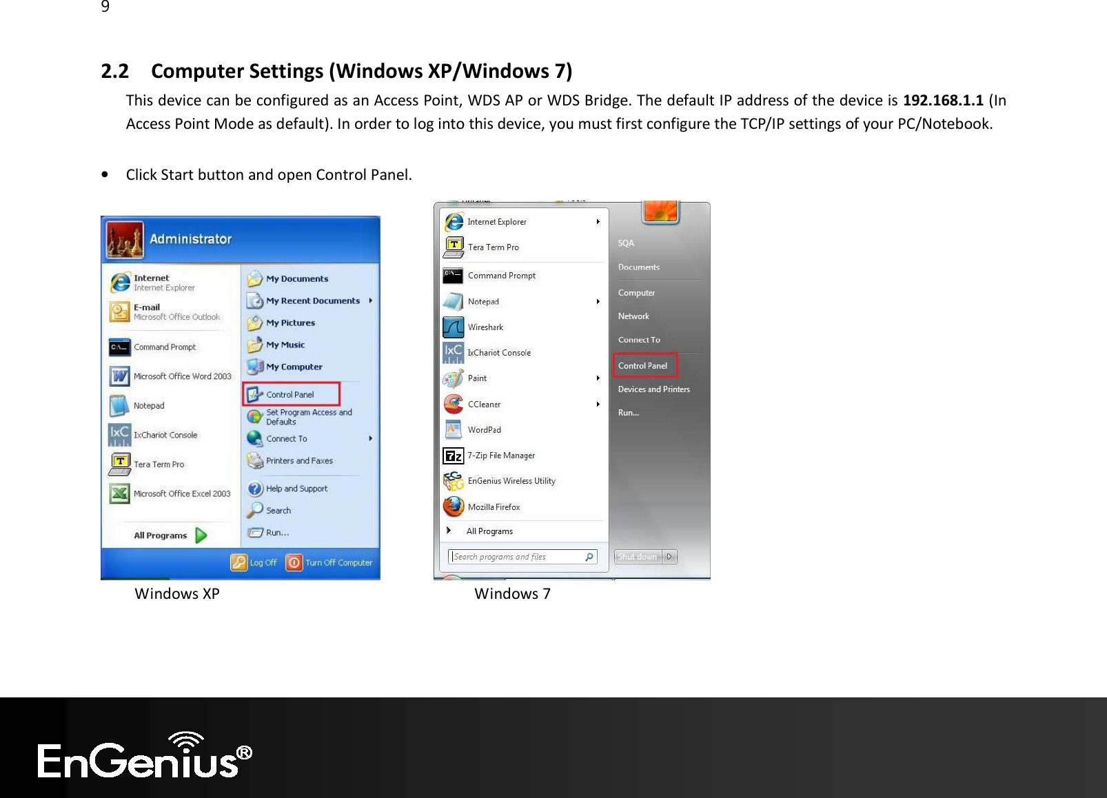
![10 • Windows XP, click [Network Connection] • Windows 7, click [View Network Status and Tasks] then [Change adapter settings] • Right click on [Local Area Connection] and select [Properties]. • Select “Internet Protocol (TCP/IP)” and click [Properties]](https://usermanual.wiki/EnGenius-Technologies/EAP300A/User-Guide-2438741-Page-11.png)
![11 • Select “Use the following IP address” and enter IP address and subnet mask then click [OK]. Note: Ensure that the IP address and subnet mask are on the same subnet as the device. For example: Device IP address: 192.168.1.1 PC IP address: 192.168.1.10 PC subnet mask: 255.255.255.0](https://usermanual.wiki/EnGenius-Technologies/EAP300A/User-Guide-2438741-Page-12.png)
![27 4.6 Monitor This page shows a histogram of the Ethernet and Wireless LAN traffic. Click on [Detail] to get the detail information.](https://usermanual.wiki/EnGenius-Technologies/EAP300A/User-Guide-2438741-Page-28.png)
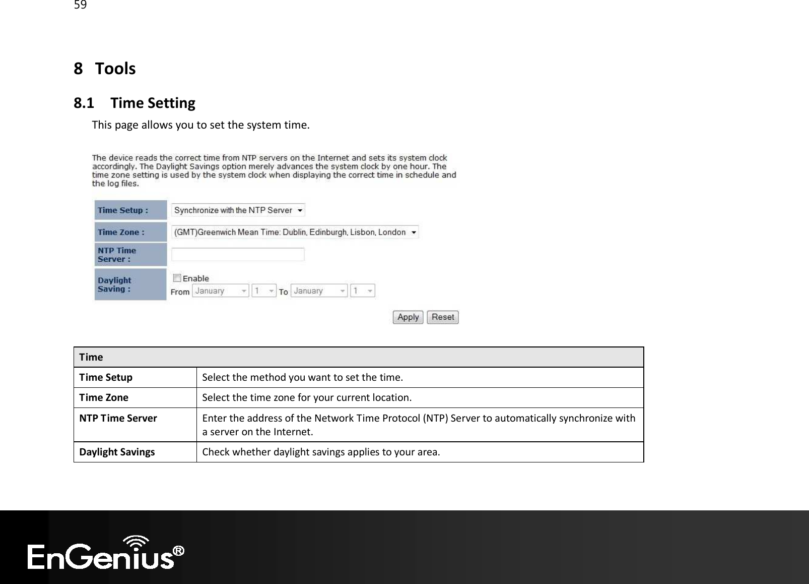
![54 7.3 Firmware Upgrade This page allows you to upgrade the device's firmware. To perform the Firmware Upgrade: 1. Click the [Browse] button and navigate to the location of the upgrade file. 2. Select the upgrade file. Its name will appear in the Upgrade File field. 3. Click the [Apply] button to commence the firmware upgrade. Note: The device is unavailable during the upgrade process, and must restart when the upgrade is completed. Any connections to or through the device will be lost.](https://usermanual.wiki/EnGenius-Technologies/EAP300A/User-Guide-2438741-Page-55.png)
![55 Emergency Upgrade If you upgrade fail, you may enter Emergency Upgrade WEB page. 1. Enter IP address: 192.168.99.9 and enter Emergency Upgrade WEB page. Note: Refer to 2.2 to configure PC/Notebook IP address to 192.168.99.8. 2. Click the [Browse] button and navigate to the location of the upgrade file and then click [Upload]. 3. Wait for 60 seconds for firmware upgrade and reboot the device. 4. You can access the device again.](https://usermanual.wiki/EnGenius-Technologies/EAP300A/User-Guide-2438741-Page-56.png)
![57 7.4 Configure This page allows you to save the current device configurations. When you save the configurations, you also can re-load the saved configurations into the device through the [Restore Settings]. If extreme problems occur you can use the [Restore to Factory Defaults] to set all configurations to its original default settings. Configure Restore to Factory Default Restores the device to factory default settings. Backup Settings Save the current configuration settings to a file. Restore Settings Restores a previously saved configuration file. Click Browse to select the file. Then Upload to load the settings.](https://usermanual.wiki/EnGenius-Technologies/EAP300A/User-Guide-2438741-Page-58.png)
![58 7.5 Reset In some circumstances it may be required to force the device to reboot. Click on [Apply] to reboot.](https://usermanual.wiki/EnGenius-Technologies/EAP300A/User-Guide-2438741-Page-59.png)
![62 9 Logout Click on [Logout] button to logout.](https://usermanual.wiki/EnGenius-Technologies/EAP300A/User-Guide-2438741-Page-63.png)
![66 0560 Česky [Czech] [Jméno výrobce] tímto prohlašuje, že tento [typ zařízení] je ve shodě se základními požadavky a dalšími příslušnými ustanoveními směrnice 1999/5/ES. Dansk [Danish] Undertegnede [fabrikantens navn] erklærer herved, at følgende udstyr [udstyrets typebetegnelse] overholder de væsentlige krav og øvrige relevante krav i direktiv 1999/5/EF. Deutsch [German] Hiermit erklärt [Name des Herstellers], dass sich das Gerät [Gerätetyp] in Übereinstimmung mit den grundlegenden Anforderungen und den übrigen einschlägigen Bestimmungen der Richtlinie 1999/5/EG befindet. Eesti [Estonian] Käesolevaga kinnitab [tootja nimi = name of manufacturer] seadme [seadme tüüp = type of equipment] vastavust direktiivi 1999/5/EÜ põhinõuetele ja nimetatud direktiivist tulenevatele teistele asjakohastele sätetele. English Hereby, [name of manufacturer], declares that this [type of equipment] is in compliance with the essential requirements and other relevant provisions of Directive 1999/5/EC. Español [Spanish] Por medio de la presente [nombre del fabricante] declara que el [clase de equipo] cumple con los requisitos esenciales y cualesquiera otras disposiciones aplicables o exigibles de la Directiva 1999/5/CE. Ελληνική [Greek] ΜΕ ΤΗΝ ΠΑΡΟΥΣΑ [name of manufacturer] ΔΗΛΩΝΕΙ ΟΤΙ [type of equipment] ΣΥΜΜΟΡΦΩΝΕΤΑΙ ΠΡΟΣ ΤΙΣ ΟΥΣΙΩΔΕΙΣ ΑΠΑΙΤΗΣΕΙΣ ΚΑΙ ΤΙΣ ΛΟΙΠΕΣ ΣΧΕΤΙΚΕΣ ΔΙΑΤΑΞΕΙΣ ΤΗΣ ΟΔΗΓΙΑΣ 1999/5/ΕΚ. Français [French] Par la présente [nom du fabricant] déclare que l'appareil [type d'appareil] est conforme aux exigences essentielles et aux autres dispositions pertinentes de la directive 1999/5/CE. Italiano [Italian] Con la presente [nome del costruttore] dichiara che questo [tipo di apparecchio] è conforme ai requisiti essenziali ed alle altre disposizioni pertinenti stabilite dalla direttiva 1999/5/CE.](https://usermanual.wiki/EnGenius-Technologies/EAP300A/User-Guide-2438741-Page-67.png)
![67 Latviski [Latvian] Ar šo [name of manufacturer / izgatavotāja nosaukums] deklarē, ka [type of equipment / iekārtas tips] atbilst Direktīvas 1999/5/EK būtiskajām prasībām un citiem ar to saistītajiem noteikumiem. Lietuvių [Lithuanian] Šiuo [manufacturer name] deklaruoja, kad šis [equipment type] atitinka esminius reikalavimus ir kitas 1999/5/EB Direktyvos nuostatas. Nederlands [Dutch] Hierbij verklaart [naam van de fabrikant] dat het toestel [type van toestel] in overeenstemming is met de essentiële eisen en de andere relevante bepalingen van richtlijn 1999/5/EG. Malti [Maltese] Hawnhekk, [isem tal-manifattur], jiddikjara li dan [il-mudel tal-prodott] jikkonforma mal-ħtiġijiet essenzjali u ma provvedimenti oħrajn relevanti li hemm fid-Dirrettiva 1999/5/EC. Magyar [Hungarian] Alulírott, [gyártó neve] nyilatkozom, hogy a [... típus] megfelel a vonatkozó alapvetõ követelményeknek és az 1999/5/EC irányelv egyéb elõírásainak. Polski [Polish] Niniejszym [nazwa producenta] oświadcza, że [nazwa wyrobu] jest zgodny z zasadniczymi wymogami oraz pozostałymi stosownymi postanowieniami Dyrektywy 1999/5/EC. Português [Portuguese] [Nome do fabricante] declara que este [tipo de equipamento] está conforme com os requisitos essenciais e outras disposições da Directiva 1999/5/CE. Slovensko [Slovenian] [Ime proizvajalca] izjavlja, da je ta [tip opreme] v skladu z bistvenimi zahtevami in ostalimi relevantnimi določili direktive 1999/5/ES. Slovensky [Slovak] [Meno výrobcu] týmto vyhlasuje, že [typ zariadenia] spĺňa základné požiadavky a všetky príslušné ustanovenia Smernice 1999/5/ES. Suomi [Finnish] [Valmistaja = manufacturer] vakuuttaa täten että [type of equipment = laitteen tyyppimerkintä] tyyppinen laite on direktiivin 1999/5/EY oleellisten vaatimusten ja sitä koskevien direktiivin muiden ehtojen mukainen. Svenska [Swedish] Härmed intygar [företag] att denna [utrustningstyp] står I överensstämmelse med de väsentliga egenskapskrav och övriga relevanta bestämmelser som framgår av direktiv 1999/5/EG.](https://usermanual.wiki/EnGenius-Technologies/EAP300A/User-Guide-2438741-Page-68.png)