EnGenius Technologies EDS5255 2 Megapixel Wireless Bullet Camera User Manual
EnGenius Technologies 2 Megapixel Wireless Bullet Camera Users Manual
UserManual.wiki
>
EnGenius Technologies
>
EDS5255 User Manual
Users Manual
Navigation menu
Upload a User Manual
Namespaces
Wiki Guide
HTML
PDF
Info
Views
User Manual
Discussion / Help
Navigation
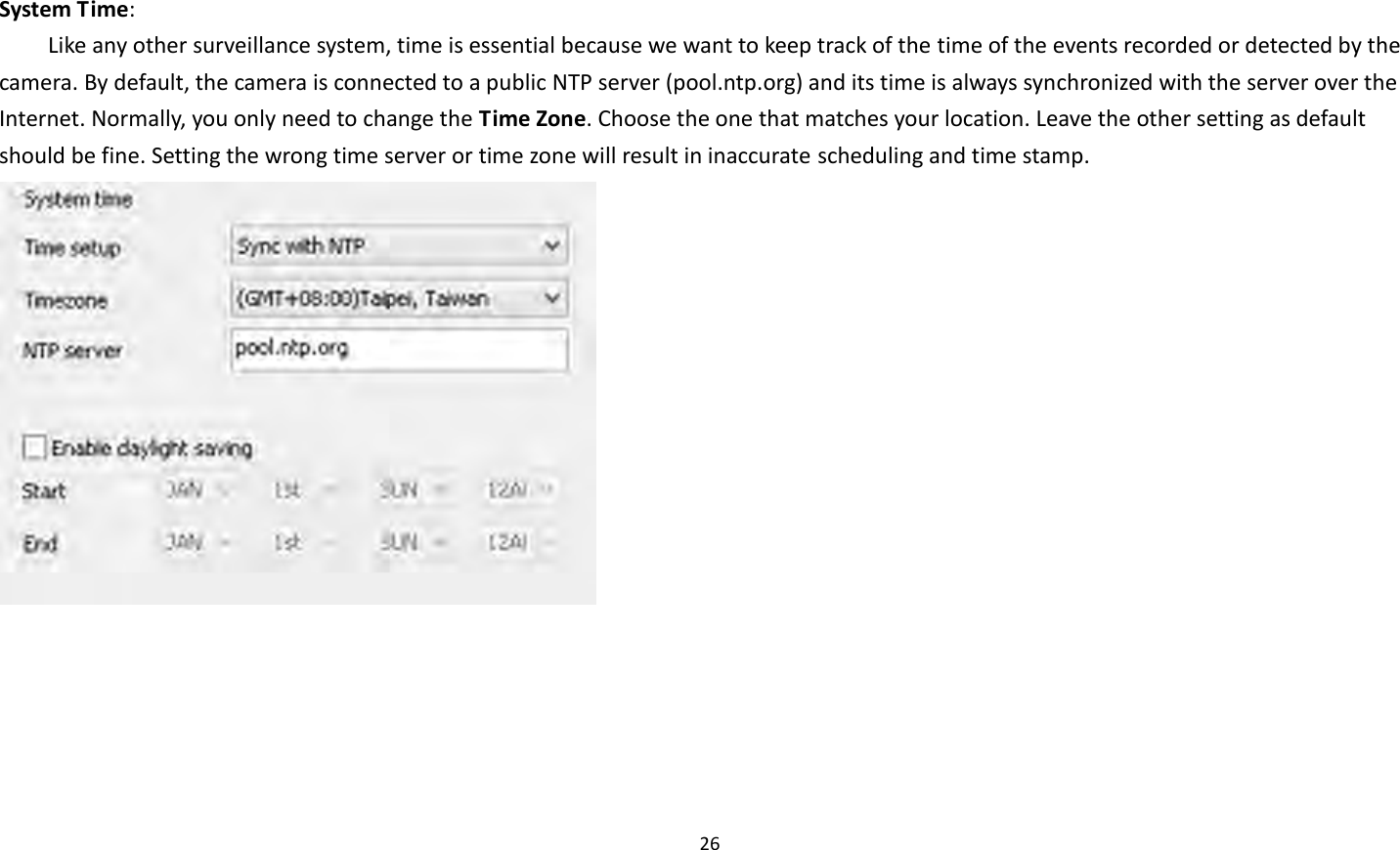
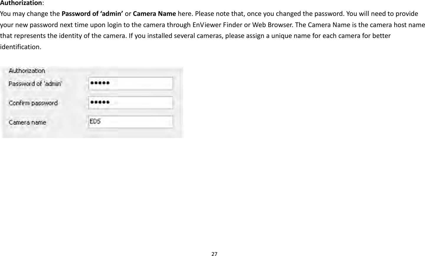
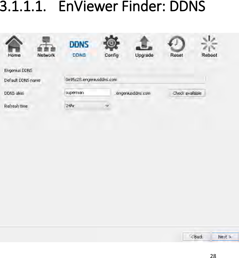
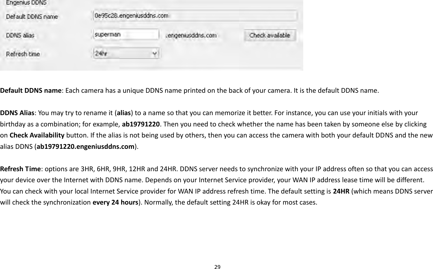

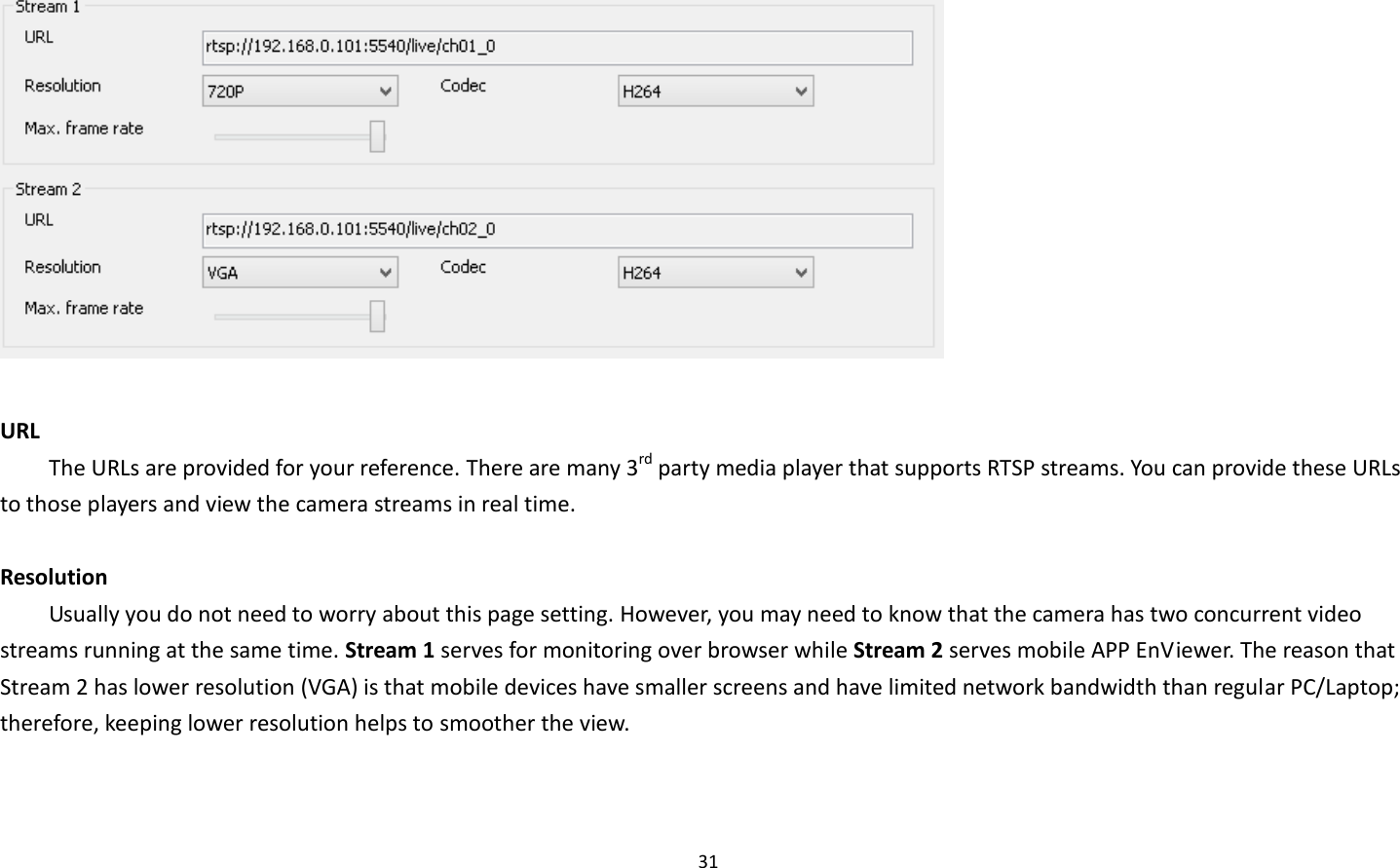


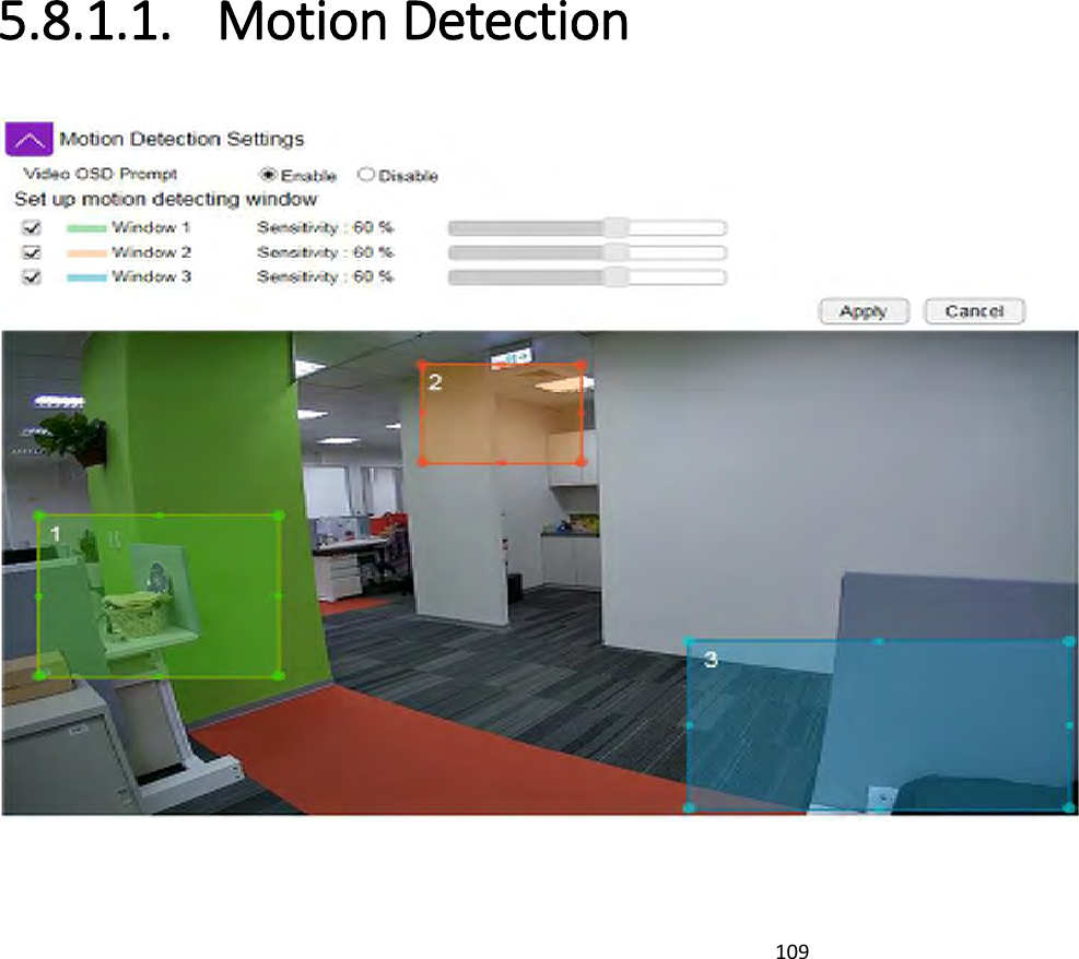
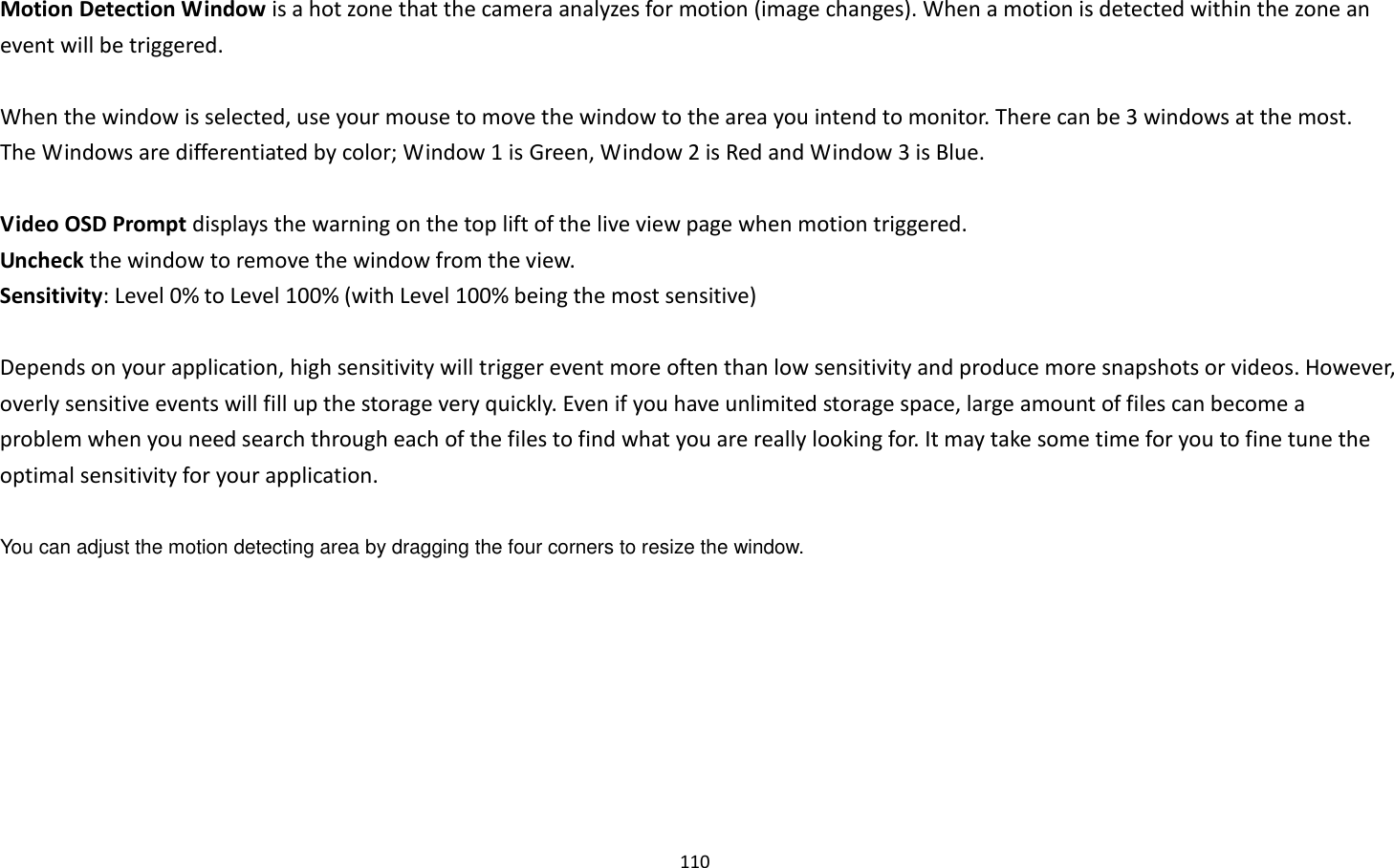
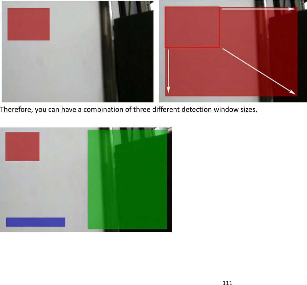
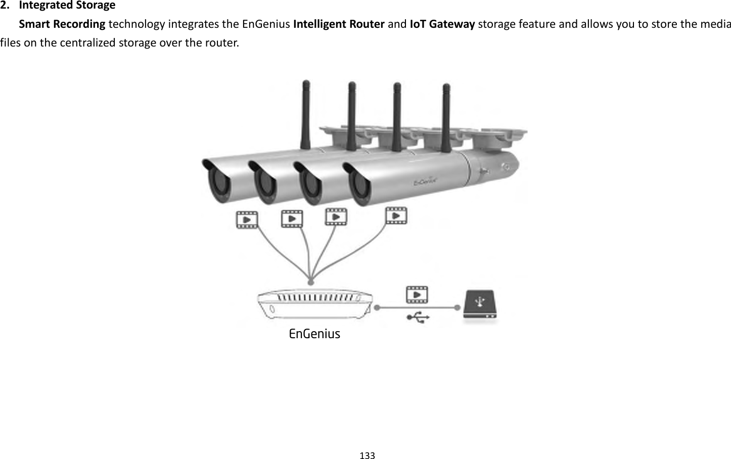
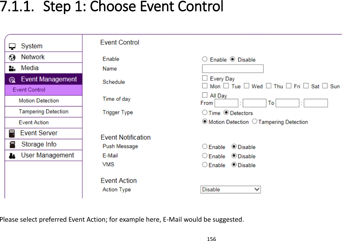
![155 7.1. Example: Remote Surveillance and Motion Detection. The application concept diagram shows a camera monitoring the property like office or warehouse. The management staff wants to remotely monitor their responsible property and needs to be alarmed when motion (intrusion) is detected. Internet [ On Business ] [ Office / Ware house ]](https://usermanual.wiki/EnGenius-Technologies/EDS5255/User-Guide-2862972-Page-156.png)