EnGenius Technologies EDS6115 Megapixel Wi-Fi Dome Camera User Manual
EnGenius Technologies Megapixel Wi-Fi Dome Camera
User Manual.pdf
EDS6115
User’s Manual
Table of Content
1. Product Overview ................................................................................................................................................................................................ 6
1.1. Introduction ................................................................................................................................................................................................. 6
1.2. Read Before Using ........................................................................................................................................................................................ 7
1.3. Key Features ................................................................................................................................................................................................. 8
1.4. Package Contents ......................................................................................................................................................................................... 9
1.5. Physical Description ................................................................................................................................................................................... 10
2. Installation ......................................................................................................................................................................................................... 11
2.1. Hardware Setup ......................................................................................................................................................................................... 11
2.2. Ceiling / Wall Mount .................................................................................................................................................................................. 15
2.3. IP Camera Connection ................................................................................................................................................................................ 17
2.3.1. Connecting via Ethernet Cable ................................................................................................................................................................... 18
2.3.2. Connecting via Wi-Fi Setup ........................................................................................................................................................................ 19
3. Accessing the Camera after Installation ............................................................................................................................................................ 20
3.1. Managing using PC or Laptop .................................................................................................................................................................... 21
3.1.1. EnViewer Finder ......................................................................................................................................................................................... 21
3.1.1.1. EnViewer Finder: Network ................................................................................................................................................................. 24
3.1.1.2. EnViewer Finder: DDNS...................................................................................................................................................................... 29
3.1.1.3. EnViewer Finder: Config..................................................................................................................................................................... 31
3.1.1.4. EnViewer Finder: Upgrade ................................................................................................................................................................. 34
3.1.1.5. EnViewer Finder: Reset ...................................................................................................................................................................... 35
3.1.1.6. EnViewer Finder: Reboot ................................................................................................................................................................... 36
3.1.2. Web Browser .............................................................................................................................................................................................. 37
3.2. Manage using Tablet or Mobile Phones .................................................................................................................................................... 39
4. First Time Basic Settings ..................................................................................................................................................................................... 40
4.1.1. Setting the Interface Language .................................................................................................................................................................. 46
4.1.2. Changing the Camera Name ...................................................................................................................................................................... 47
4.1.3. Setting the Camera Time............................................................................................................................................................................ 49
4.1.4. Setting the Storage Folder ......................................................................................................................................................................... 50
4.1.5. Adding a User Account ............................................................................................................................................................................... 51
4.1.6. Wireless Setting ......................................................................................................................................................................................... 52
5. User Interface ..................................................................................................................................................................................................... 56
5.1. Navigation Panel ........................................................................................................................................................................................ 57
5.2. Live View Settings ...................................................................................................................................................................................... 61
5.3. Main Menus ............................................................................................................................................................................................... 64
5.4. System ........................................................................................................................................................................................................ 66
5.4.1. Status.......................................................................................................................................................................................................... 67
5.4.2. Service Port ................................................................................................................................................................................................ 69
5.4.3. Time ........................................................................................................................................................................................................... 70
5.4.4. PC Storage Path .......................................................................................................................................................................................... 71
5.4.5. Firmware .................................................................................................................................................................................................... 72
5.4.6. Back-up ...................................................................................................................................................................................................... 75
5.4.7. Reboot/Reset to Default ............................................................................................................................................................................ 80
5.4.8. Language .................................................................................................................................................................................................... 81
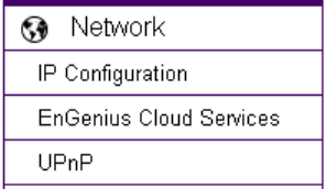
5.5. Network ..................................................................................................................................................................................................... 82
5.5.1. IP Configuration ......................................................................................................................................................................................... 83
5.5.2. EnGenius Cloud Service ............................................................................................................................................................................. 87
5.5.3. UPnP ........................................................................................................................................................................................................... 92
5.6. Wireless ...................................................................................................................................................................................................... 93
5.6.1. Basic ........................................................................................................................................................................................................... 94
5.6.2. WPS ............................................................................................................................................................................................................ 97
5.6.3. AP Profile .................................................................................................................................................................................................... 99
5.6.3.1. Add ................................................................................................................................................................................................... 100
5.6.3.2. Edit ................................................................................................................................................................................................... 102
5.6.3.3. Move Up / Down .............................................................................................................................................................................. 103
5.6.3.4. Delete ............................................................................................................................................................................................... 104
5.6.3.5. Connect ............................................................................................................................................................................................ 104
5.7. Media ....................................................................................................................................................................................................... 106
5.7.1. Video ........................................................................................................................................................................................................ 107
5.7.2. Camera ..................................................................................................................................................................................................... 109
5.7.2.1. Light Setting ..................................................................................................................................................................................... 110
5.7.2.2. Flicker Control .................................................................................................................................................................................. 113
5.7.2.3. Mirror ............................................................................................................................................................................................... 114
5.7.2.4. Day/Night Mode ............................................................................................................................................................................... 116
5.7.3. Advanced .................................................................................................................................................................................................. 117
5.7.4. Privacy Mask ............................................................................................................................................................................................ 119
5.7.5. Audio ........................................................................................................................................................................................................ 120
5.8. Event Server ............................................................................................................................................................................................. 122
5.8.1. Network Storage ...................................................................................................................................................................................... 123
5.8.1.1. NFS (Network File System) ............................................................................................................................................................... 125
5.8.1.2. SAMBA.............................................................................................................................................................................................. 126
5.8.2. FTP (File Transfer Protocol) ...................................................................................................................................................................... 127
5.8.3. E-mail Alerts ............................................................................................................................................................................................. 128
5.8.4. SD Card ..................................................................................................................................................................................................... 130
5.9. Event Management .................................................................................................................................................................................. 133
5.9.1. Setup Wizard ............................................................................................................................................................................................ 134
5.9.1.1. Wizard – Schedule Recording................................................................................................................................................................... 135
5.9.1.2. Wizard – Event ....................................................................................................................................................................................... 140
5.9.2. Event Control ............................................................................................................................................................................................ 148
5.9.3. Schedule Recording .................................................................................................................................................................................. 154
5.10. User Management ................................................................................................................................................................................... 156
5.10.1. Add User ................................................................................................................................................................................................... 158
5.10.2. Edit User ................................................................................................................................................................................................... 159
5.10.3. Delete User .............................................................................................................................................................................................. 161
6. Camera Connecting to EnGenius Router ......................................................................................................................................................... 163
6.1. Enable Router Storage Function .............................................................................................................................................................. 166
6.2. Camera Profile .......................................................................................................................................................................................... 170
6.2.1. Add Profile ................................................................................................................................................................................................ 170
6.2.2. Edit Profile ................................................................................................................................................................................................ 173
6.2.3. Delete Profile ........................................................................................................................................................................................... 174
6.2.4. Synchronize .............................................................................................................................................................................................. 175
6.3. Fine Tune Camera Configuration set by the Router ................................................................................................................................. 176
6.3.1. Camera Storage Setting ............................................................................................................................................................................ 177
6.3.2. Camera Event Setting ............................................................................................................................................................................... 179
6.3.3. Camera Motion Detection Setting ........................................................................................................................................................... 180
6.4. Access the Media files on the Router ...................................................................................................................................................... 181
6.4.1. Using web browser .................................................................................................................................................................................. 181
6.4.2. Using Windows File Explorer ................................................................................................................................................................... 185
7. Camera Connecting to Other Router ............................................................................................................................................................... 188
8. Application Guide ............................................................................................................................................................................................. 189
8.1. Example 1: Remote Surveillance and Motion Detection. ........................................................................................................................ 191
8.1.1. Step 1: Choose Event Control ................................................................................................................................................................... 192
8.1.2. Step 2: Configure Motion Detection ........................................................................................................................................................ 193
8.1.3. Step 3: Configure Event Action ................................................................................................................................................................ 194
9. Trouble Shooting .............................................................................................................................................................................................. 196
9.1. Viewing Your Video .................................................................................................................................................................................. 196
9.2. Networking ............................................................................................................................................................................................... 197
9.3. Security and Privacy ................................................................................................................................................................................. 198
9.4. Cloud Video Services ................................................................................................................................................................................ 198
10. Appendix .................................................................................................................................................................................................. 199
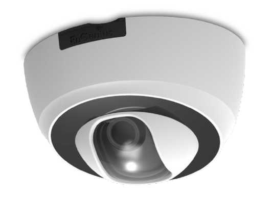
1. Product Overview
The EDS6115 is a 1-Megapixel Day & Night Wi-Fi Dome Network Camera which adds surveillance capability to a variety of network
environments. With a built-in removable mechanical IR-cut filter, it helps users keep an eye on what matters and get notified by what just
happened on demand allowing 24/7 monitoring remotely.
It features LED Infrared Night Vision with automatic activation system. Megapixel HD with High speed H.264 encoding ensures high quality
image recording without losing any details. Infrared Night Vision feature can assist to deliver 24/7 non-stop monitoring. With the support of
patented EnGenius Cloud service, users can monitor their surveillance networks remotely in real time any time anywhere on any computer or
on iOS or Android based mobile devices using EnGenius APPs.
1.1. Introduction
This document will guide you through detail steps for EDS6115 installation and both basic and advanced configurations. Familiarizing with
the product features can help you to fully utilize the camera for various application scenarios. Please note that the product feature may
improve over time, be sure to check out the latest firmware and user’s manual for most updated changes on EnGenius web site.
Thank you for choosing EnGenius products.
1.2. Read Before Using
For users’ convenience, the camera is configured with DHCP enabled by default which allows the camera to get an IP address for itself
automatically. This applies to majority of the surveillance network settings. However, if you are connecting the product in an office (or any
public setting), you may need to consult the IT department in charged for IP setting detail to avoid IP address conflict.
Like all electronic devices, do not install the product in hazardous environment where humidity or temperature is high to avoid danger.
This camera is designed for indoor usage; when the camera is wall-mount installed, please secure the camera and wires in place to prevent it
from dangling.

1.3. Key Features
Megapixel HD Resolution to Deliver Quality Streaming on A Variety of Mobile Devices and PCs
LED Infrared Night Vision up to 32 Feet (10 Meters) with Automatic Activation System
Wireless N Network Compliant with Optimum Wi-Fi Performance
Supports Simultaneous Dual-Stream Recording with High Speed H.264 Encoding
Built-in Microphone
Multiple Storage Options–Built-in Micro SD/SDHC Slot for Onboard Storage and Samba/FTP Client to Save to an External Storage
Supports Push Message and Play Back on Smart Devices triggered by Motion/Sound Detection
EnGenius Cloud Services Supported (Apps and Web-based Services)
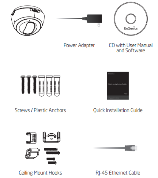
1.4. Package Contents
The package should contain all of following items shown below.
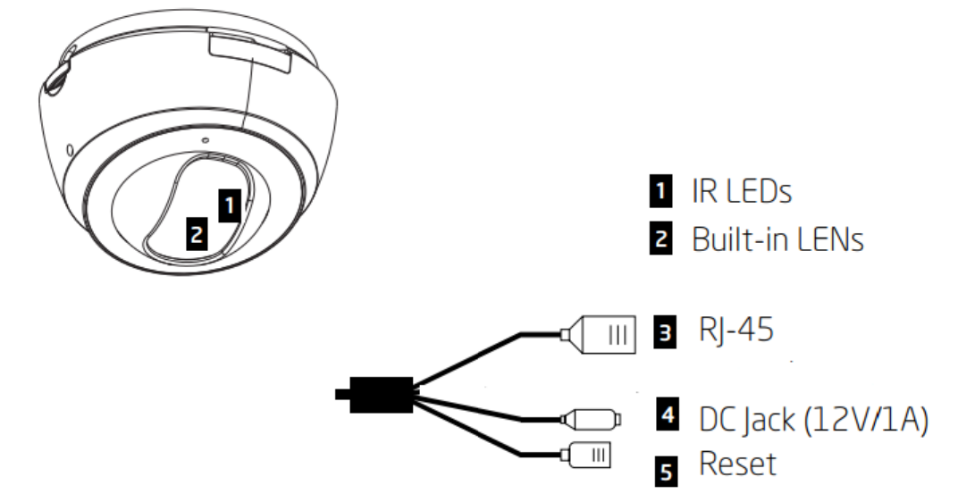
1.5. Physical Description
2. Installation
2.1. Hardware Setup
Before installing the camera, please make sure the camera is properly configured and tested before hardware installation especially if it is
mounted on a wall. Please also make sure the power outlet is available near the installation site.
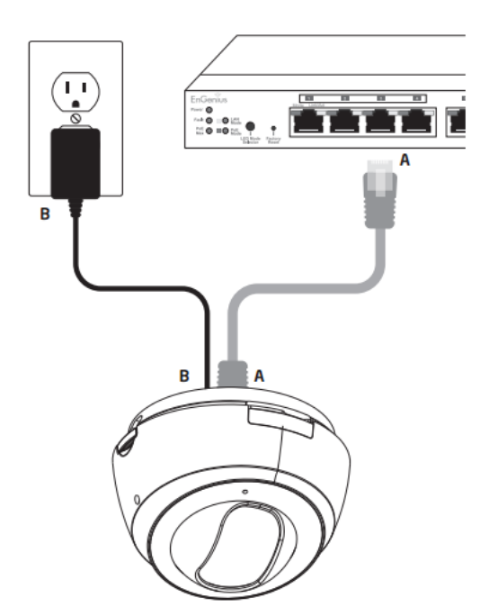
I. Basic Connection without PoE
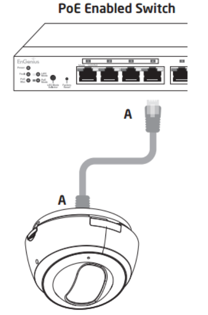
II. PoE Connection—Option 1
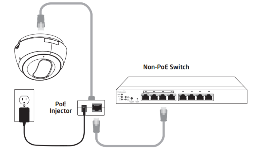
III. PoE Connection—Option 2
When connecting to a non-PoE switch, please connect the camera to a switch via PoE injector (optional).
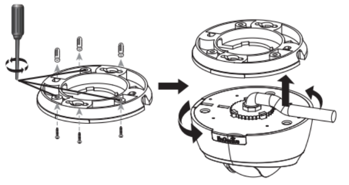
2.2. Ceiling / Wall Mount
Locate an area on the ceiling / wall and make sure the area is capable of supporting the weight of camera.
Use the ceiling mount bracket screw slots to drill the mounting screws into the ceiling or wall.
Twist the camera body into the ceiling mount bracket and route cables into the side of conduit entry tunnel.
Twist the camera to set counter-clockwise carefully and slowly until it is secured firmly.
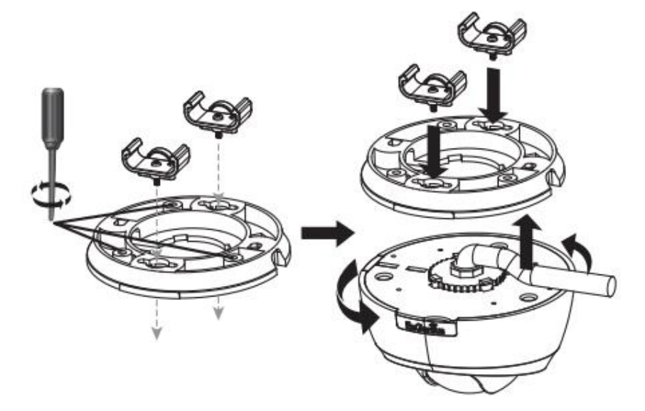
For Installation with ceiling mount hooks into the ceiling light grid steel framing, first use the hooks and screw into the ceiling mount bracket
until fixed upon the ceiling light grid steel framing. When done, twist the camera until it is secured.

2.3. IP Camera Connection
Before setting up the camera with your router, please ensure the Internet is ready. When camera is configured with the router with
Internet connection, you can then access the camera through the Internet anytime anywhere. This section will guide you through the
connection setup. Please follow the following guide step by step to setup the connection between your camera and the router. There are two
ways to establish connection between the camera and router: Wired (Ethernet) and Wireless (Wi-Fi).
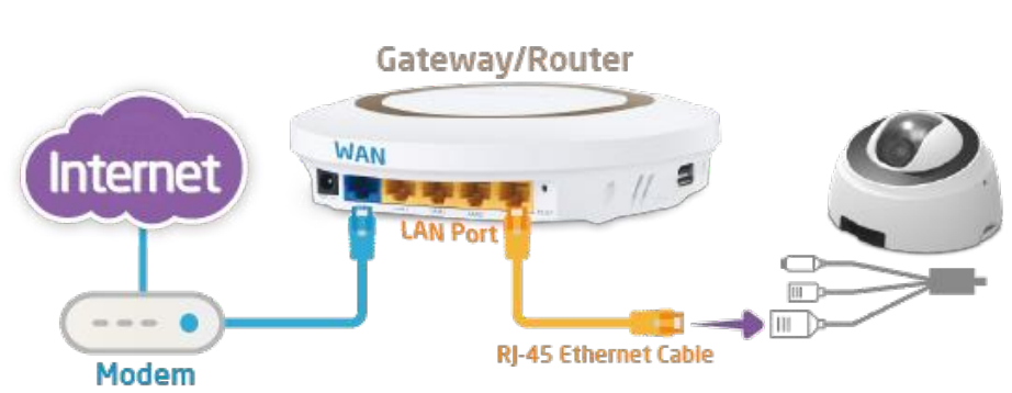
2.3.1. Connecting via Ethernet Cable
Connect the camera to the router on the LAN ports with a network CAT5 RJ45 Ethernet cable (shown below). You may use the cable that
came with the package for initial setup; however, you may be required to switch to wireless setting or purchase a longer cable to extend the
camera for longer range. As a rule of thumb, if your camera is close enough to the router use Ethernet cable if possible for optimized result;
and for wall mount installation, it’s best to adopt wireless setup. You can choose either way for the application you find suitable.

2.3.2. Connecting via Wi-Fi Setup
It is recommended that to make initial setup with RJ45 Ethernet cable and then switch to wireless after you have completed all the
settings. However, you can also start wirelessly with WPS mechanism.
Ensure the router supports WPS feature and is enabled. Press the WPS button on both camera and the router at the same time. It may
take up to 90 seconds for the two devices to establish the connection. Make sure you are close enough to the router and ensure the router is
not occupied by heavy traffic or P2P loading.
Please note that there may be differences in WPS between vendors; therefore, if router does not respond to camera connection request
please use RJ45 cable for initial setup and manually configure wireless setting afterwards.
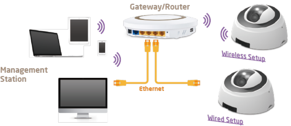
3. Accessing the Camera after Installation
There are several ways to get access to your camera on your network. You should probably have a setup similar to the following diagram.
You can manage the camera using your PC, Laptop, Tablet or iOS/Android based mobile phone; we will call it management station in the
following context. The key point is that management station and the camera must be connected under the same subnet.
3.1. Managing using PC or Laptop
3.1.1. EnViewer Finder
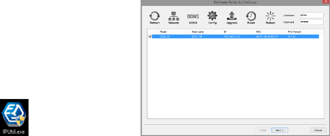
EnViewer Finder is a tool provided by EnGenius that helps you discover the camera within a local network. You should be able to find the tool
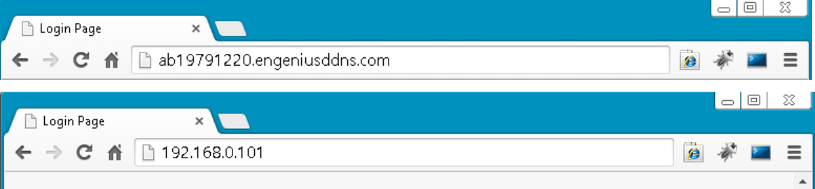
inside the CD. Please install the tool to your management station desktop for quick access when you need it. Please take note of the IP address
shown. In this example, 192.168.0.101 is the camera IP address.
Double-click on the icon to run.
The camera list at the center displays the discovered cameras currently connected to your router (local network). If you do not find the
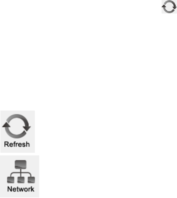
one you intend to configure, please click on Refresh to rescan the network until it appears on the list. Please turn off any heavy-loading
applications such as P2P that may occupy your network.
Enter Username and Password for the selected camera on the list.
Click on Next to start configuration.
The EnViewer Finder will guide you step by step through the basic settings Network, DDNS and Config. You can also switch between settings by
clicking the icons on the panel.
Rescan the network for camera.
Go to Network setting

Go to DDNS setting
Go to Camera Video Configuration setting
Upgrade the current camera firmware
Reset the current camera to factory default
Reboot/restart the current camera
3.1.1.1. EnViewer Finder: Network
MODE: There are three modes that your camera can get its IP address. DHCP, Manually, or PPPoE.
DHCP:
It is the most popular way in the home network setting. It will request IP address from your router automatically. The requirement is that your
router should enable DHCP (which is basically the default setting for most of the home router vendors). You are not required to enter any IP
related information.
Manual:
You will need to assign the IP address details in TCP/IP section. Please ensure that the IP address is not being used by someone else in the
network.
PPPoE:
If you are connecting to the Internet without going through your router, you can connect the camera directly to your modem (given that
your Internet service is using PPPoE protocol). Please consult your local ISP provider for more detail. Basically, the PPPoE setting is exactly the
same as your router. You need to provide at least the Username and Password to get access.
UPnP: this feature must be enabled so that the camera can be discovered by UPnP services. Leave it enabled if you unsure what UPnP is.
System Time:
Like any other surveillance system, time is essential because we want to keep track of the time of the events recorded or detected by the
camera. By default, the camera is connected to a public NTP server (pool.ntp.org) and its time is always synchronized with the server over the
Internet. Normally, you only need to change the Time Zone. Choose the one that matches your location. Leave the other setting as default
should be fine. Setting the wrong time server or time zone will result in inaccurate scheduling and time stamp.
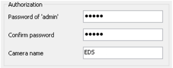
Authorization:
You may change the Password of ‘admin’ or Camera Name here. Please note that, once you changed the password. You will need to provide
your new password next time upon login to the camera through EnViewer Finder or Web Browser. The Camera Name is the camera host name
that represents the identity of the camera. If you installed several cameras, please assign a unique name for each camera for better
identification.
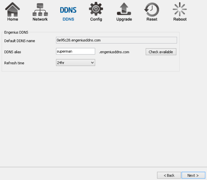
3.1.1.2. EnViewer Finder: DDNS

Default DDNS name: Each camera has a unique DDNS name printed on the back of your camera. It is the default DDNS name.
DDNS Alias: You may try to rename it (alias) to a name so that you can memorize it better. For instance, you can use your initials with your
birthday as a combination; for example, ab19791220. Then you need to check whether the name has been taken by someone else by clicking
on Check Availability button. If the alias is not being used by others, then you can access the camera with both your default DDNS and the new
alias DDNS (ab19791220.engeniusddns.com).
Refresh Time: options are 3HR, 6HR, 9HR, 12HR and 24HR. DDNS server needs to synchronize with your IP address often so that you can access
your device over the Internet with DDNS name. Depends on your Internet Service provider, your WAN IP address lease time will be different.
You can check with your local Internet Service provider for WAN IP address refresh time. The default setting is 24HR (which means DDNS server
will check the synchronization every 24 hours). Normally, the default setting 24HR is okay for most cases.
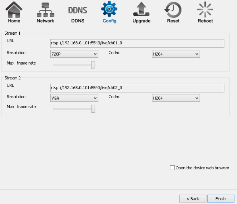
3.1.1.3. EnViewer Finder: Config
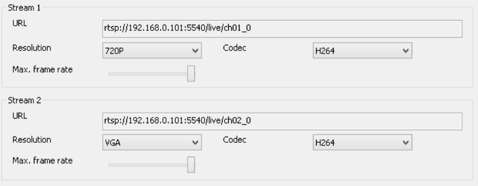
URL
The URLs are provided for your reference. There are many 3rd party media player that supports RTSP streams. You can provide these URLs
to those players and view the camera streams in real time.
Resolution
Usually you do not need to worry about this page setting. However, you may need to know that the camera has two concurrent video
streams running at the same time. Stream 1 serves for monitoring over browser while Stream 2 serves mobile APP EnViewer. The reason that
Stream 2 has lower resolution (VGA) is that mobile devices have smaller screens and have limited network bandwidth than regular PC/Laptop;
therefore, keeping lower resolution helps to smoother the view.
Codec
This setting determines what codec used for video compression. Please use the default for optimized performance. The compression
method affects overall performance and media file size. The options are reserved for advanced purposes only.
Max frame rate
This setting determines how many frames are taken per second. This setting affects the quality of the video. High frame rate results in
smoother video but larger video file.
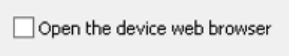
Please Select this option before hitting Finish button. This will open the web browser with the detect Camera IP address entered in the web
browser URL for you. Please bookmark it to your favorite so that you don’t have to memorize the IP address when next time you want to login
into the camera. You can also use your DDNS name to access the camera management page. Either way works fine.
Click Finish when completed.
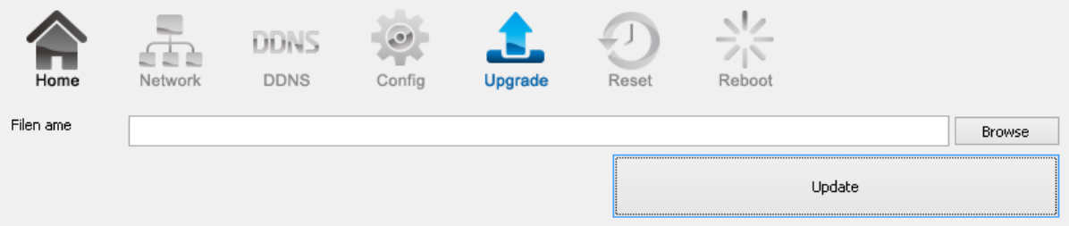
3.1.1.4. EnViewer Finder: Upgrade
EnViewer Finder also allows you to upgrade your camera firmware. The product feature may improve over time, you may check EnGenius
official web site for the latest firmware. New firmware may contain bug fixes or feature improvement; please download the latest firmware file
to your local computer first before proceeding further:
Click Browse and select the firmware file you downloaded.
Click Update to proceed with upgrade process.
It may take a moment for the upgrade process; please wait patiently.
WARNING: Do not turn off the device in the middle of upgrade process. Terminating the device during the process will damage the device and
may cause the device to fail.
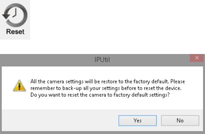
3.1.1.5. EnViewer Finder: Reset
You can reset the camera to its factory default state and your settings on the camera will be erased.
Note: It will take a while for the camera to come back on again. Therefore, the camera will not appear on the camera list if you rescan the
network before it resets to default and boots up.
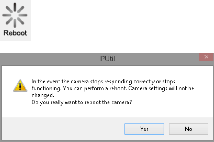
3.1.1.6. EnViewer Finder: Reboot
You can reboot the camera on EnViewer Finder if the camera stops responding for unknown reason.
Click on Yes to proceed.
Note: It will take a while for the camera to come back on again. Therefore, the camera will not appear on the camera list if you rescan the
network before it boots up.
3.1.2. Web Browser
You can use web browser on the management station to access the camera by entering IP address or DDNS of your camera. DDNS works
only if your router is connected to the Internet. Please refer to the previous section if you do not know the IP address or DDNS of your camera.
For this example we have our DDNS and IP address as follows:
DDNS: ab19791220.engeniusddns.com
IP Address: 192.168.0.101
If you are using EnGenius Intelligent Router or IoT Gateway please proceed to Manage camera over EnGenius Router chapter.
If not, please proceed to First Time Basic Setting chapter for more detail guide on camera initial settings.

EnGenius Router/Gateway
If you are using EnGenius Intelligent Router or IoT Gateway, you can manage the camera through the router management interface. The
benefit of this is that you can manage both the router and the camera on a single integrated user interface. Please refer to Manage camera
over EnGenius Router section for detail.

3.2. Manage using Tablet or Mobile Phones
You can manage your camera over Tablet or Mobile Phones using the free EnGenius APP EnViewer. EnViewer currently supports the two
most popular Android and iOS platforms. Please search the keyword “EnViewer” in Google Play or iOS Store.
4. First Time Basic Settings
Open your browser and type in the camera IP (e.g. 192.168.0.103) address or the given DDNS name printed on the label on the back of
your camera (e.g. 0f9e76a.engeniusddns.com) using a regular web browser.
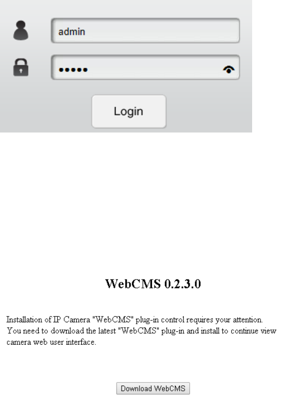
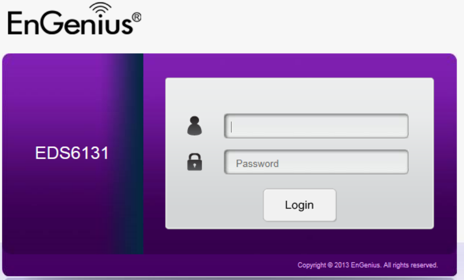
Enter the default username admin and password admin. Click Login to proceed.
For the first time of login, you will be informed to download and install “WebCMS”. Please click on “Download WebCMS“ to start download
(you will be required to have Internet connection on your router). WebCMS enables browsers to support camera feature. Don’t worry if you are
prompted with a different version number because the software upgrades from time to time.
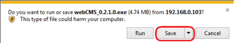
If prompted with the following question, click on Save (Internet Explorer).
Save the downloaded file.
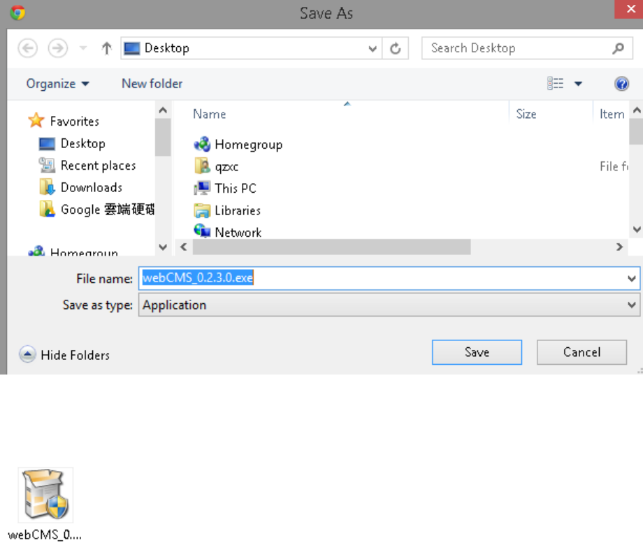
Once download is completed, you MUST close all the browsers before install WebCMS.
Double click on WebCMS to install the program. You may not have noticed, the installation is very fast, it only takes a few seconds for
WebCMS to be installed.
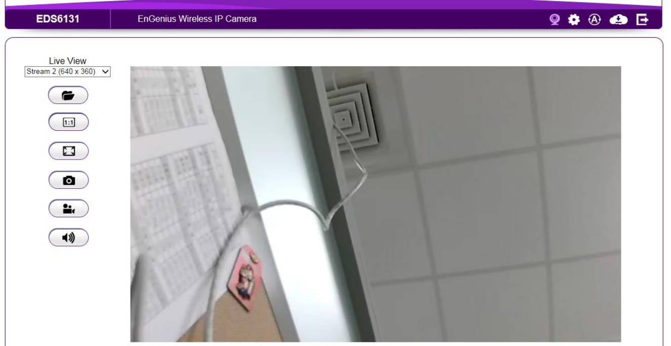
When installation is completed, open the browser and login into the camera again. You should be able to see the camera viewer in live as
shown below. If you do not see the viewer that means you did not install WebCMS properly or try login using other browsers.
NOTE: If you are seeing grey color in the viewer, it is because the camera has detected insufficient of light in the room and enabled night vision
mode automatically. If you point your camera to a brighter area, you should be able to see it switched to normal color mode. Try a few places
to get a feeling on how it works. If listening closely, you may hear the click sound from the camera when night vision is switched on and off.
Congratulations, you are now ready to proceed with further camera settings!
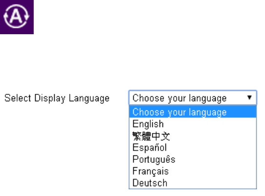
4.1.1. Setting the Interface Language
First of all you may want to change the user interface language. The default factory language is English. To change the language, click on
icon the make the change. On the language list, click to select the one you feel comfortable with from the list. The user interface with
refresh automatically with your chosen language.
4.1.2. Changing the Camera Name
On the management page, click to access the configuration Main Menu.
On the Main Menu, select Network UPnP
Then, you may want to assign the camera with proper names for better identification if you have several cameras at the same time. Meaningful
names such as living room, kitchen, baby room or any other descriptions you find suitable to describe the space being monitored.
Select Network UPnP
Hostname: Enter a new name into this field
Click Apply to change the camera name
4.1.3. Setting the Camera Time
It is crucial to setup camera time properly so that scheduling can be arranged and events be recorded with accurate date and time.
On the Main Menu, select System Time
Please refer to Chapter 3 for time setting detail.
4.1.4. Setting the Storage Folder
The Storage Folder is the location where media files will be placed.
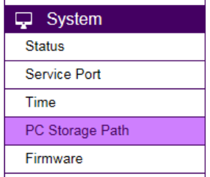
On the Main Menu, select System PC Storage Path
Please refer to Chapter 3 for detail setting
4.1.5. Adding a User Account
On the Main Menu, select User Management User Account
Please refer to Chapter 4 for User Management for adding a User.
4.1.6. Wireless Setting
Please skip this step if you only use wired setup for your camera.
Ensure your router supports wireless connection and enabled.
On the management page, click to access the configuration Main Menu.

On the other hand, we also need to enable camera’s wireless feature; please check again to ensure you have wireless enabled.
On the Main Menu, select Wireless Basic
Enable wireless by choosing Enable option

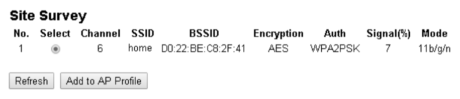
Click on Site Survey button to search for existing wireless access points (AP).
When prompted with Site Survey window, click on Refresh button if you do not find your AP on the list.
On the site list, choose your preferred AP and then click Add to AP Profile.
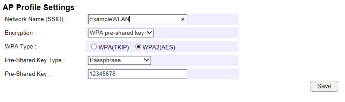
Then, on the AP Profile Settings window, please check if the security settings are correct. Please review the settings: Encryption, WPA type,
and Pre-Shared Key type. They are automatically detected. Normally, you only need to provide the Pre-Shared Key (password). However, you
can still change the settings if they do not match with the actual AP wireless security settings.
Enter your Pre-Shared Key and press Save to complete the setting.
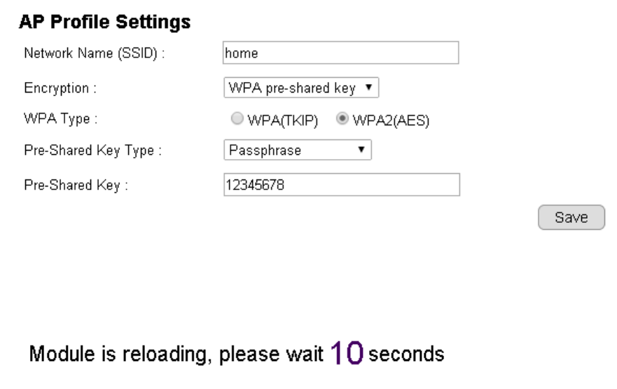
Please wait for a moment for the setup to complete.
While waiting, you can remove RJ45 Ethernet Cable from the camera. It may take a moment for the camera to detach from wired network and
switch to the newly established wireless connection with the chosen AP (your router).
To check if the connection is successful, you can verify it by login into your camera again. In case the camera is still not accessible, please check
your router again to see whether your camera is connected. Also, check the security setting again just for sure.
5. User Interface
Camera management page allows you to view and configure the camera at real time. This chapter will introduce all supported features and
detail configurations.
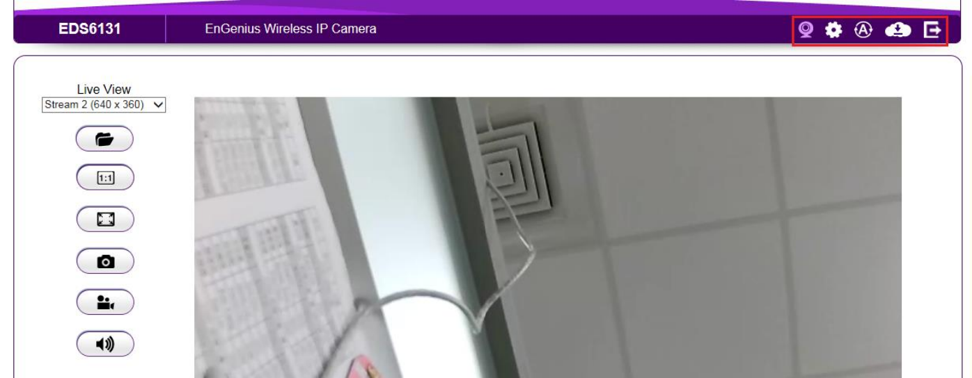
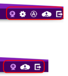
5.1. Navigation Panel
The Navigation Panel is located at the top-right corner of the page. Since there are two different user levels (Administrator and Viewer),
the functions shown on the Navigation Panel also vary accordingly. For more information about user account, please refer to User
Management section.

Administrator has full control of all the camera settings.
The viewer only has camera view features.
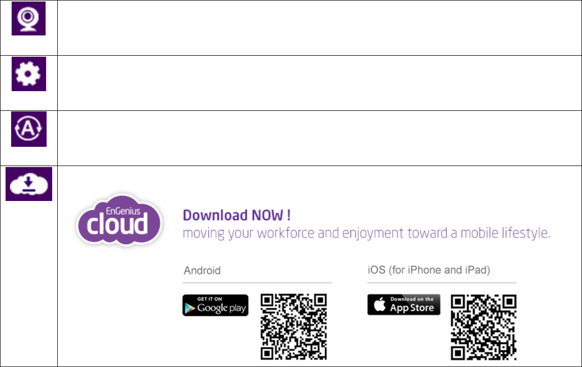
The descriptions are as follows
Switch the management page to camera viewer within which snapshots or video clips can be taken at
real time.
Switch the management page to camera setting. Please refer to Main Menu section for detail camera
setting.
Allows user to change management page language setting.
Cloud Service Page

Logout
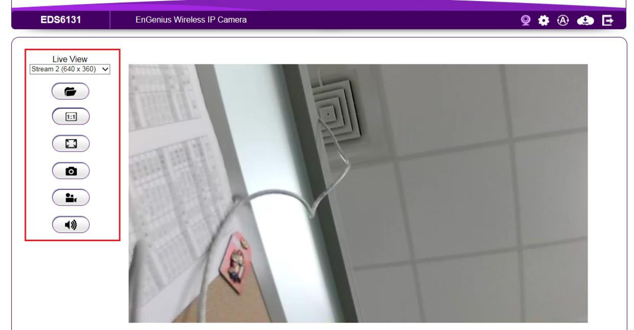
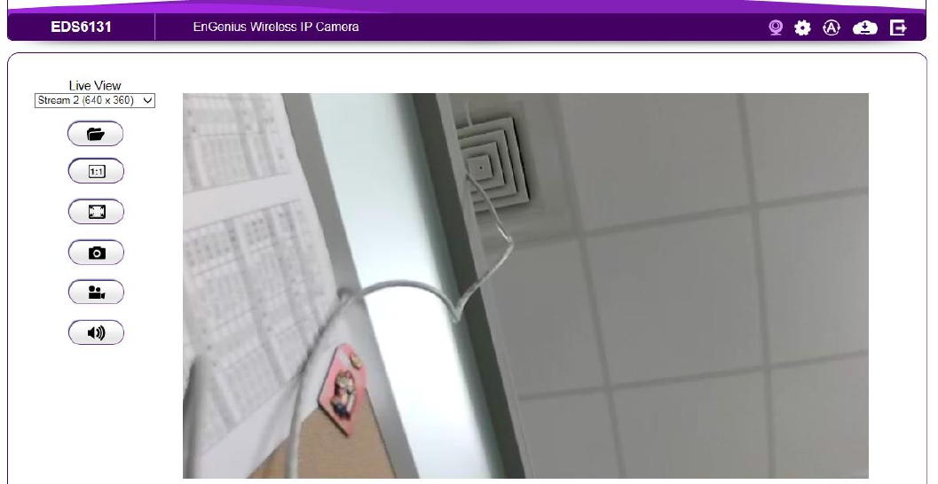
5.2. Live View Settings
The Live View Management menu is located at the right side of the page.
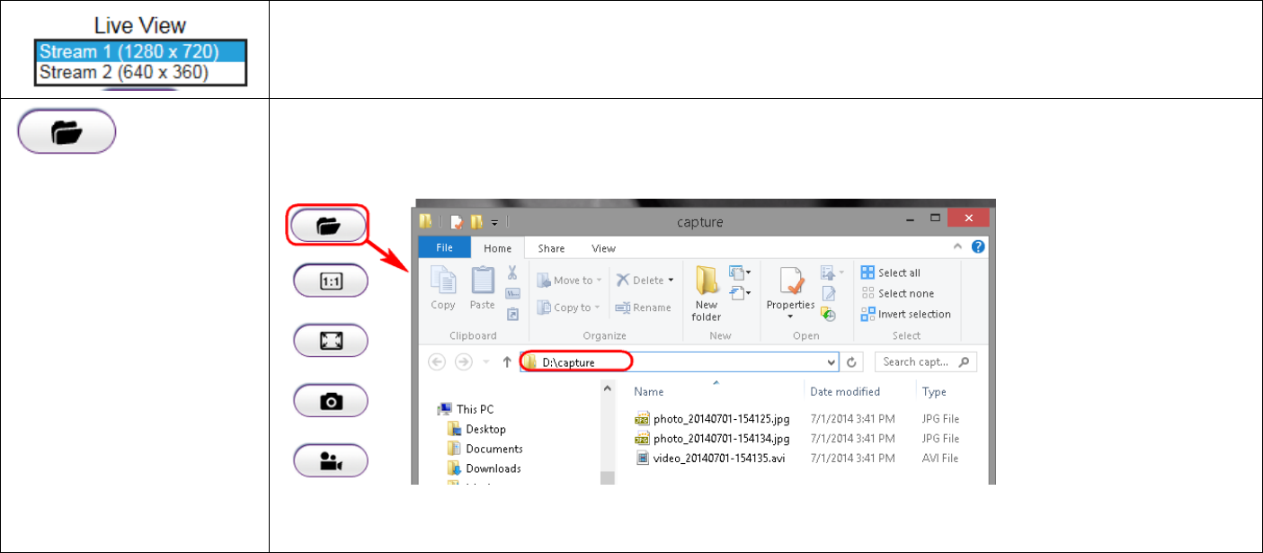
There are two streams running concurrently: Stream1 (1280 x 720) and Stream2 (640x480). Stream1 has the
higher resolution than stream2. Stream2 serves lower resolution for mobile devices which has smaller screens.
You can preview each stream at real time by selecting it from the list.
This opens the local folder where the real time captured images and clips are stored. You may change the
folder path at Main Menu System PC Storage Path
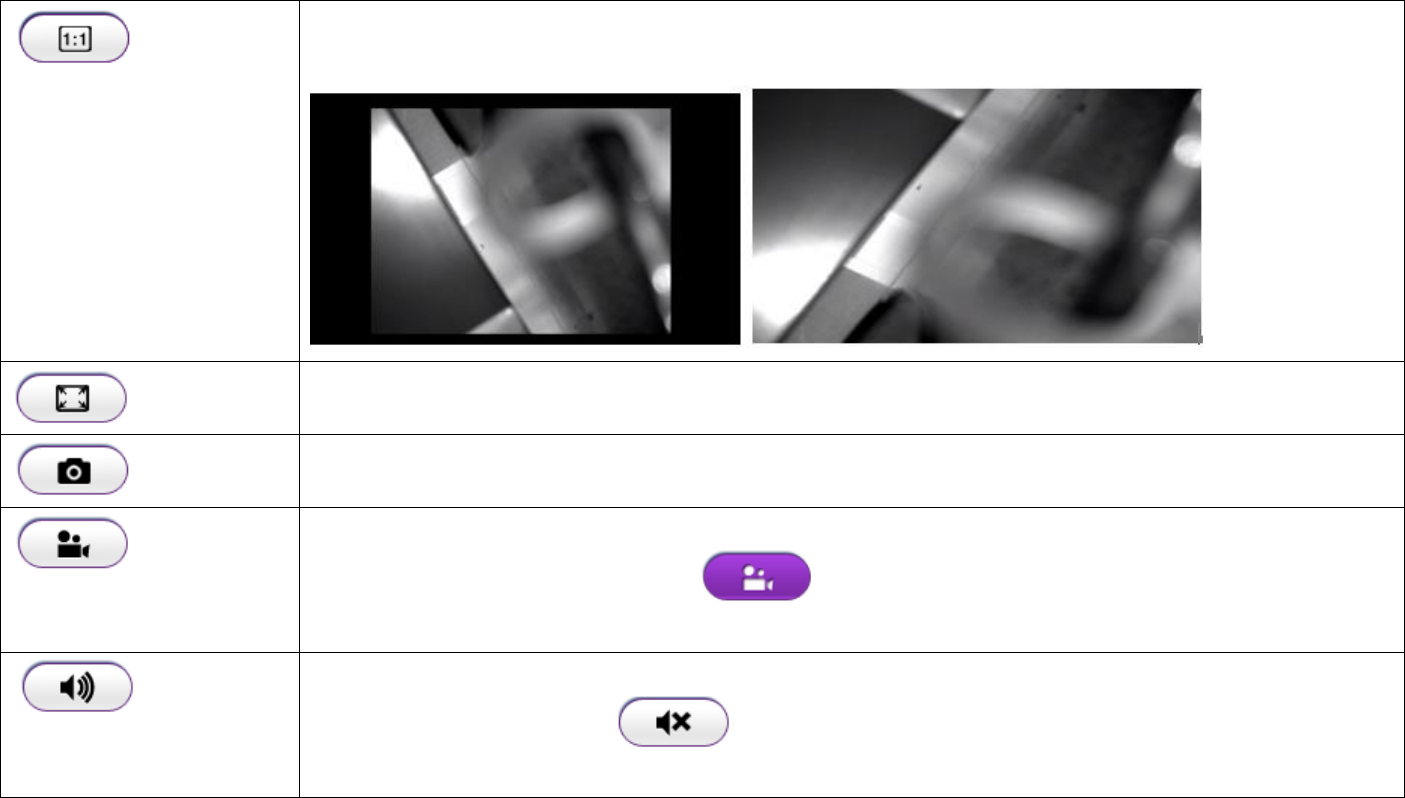
This switch only applies to resolution 640 x 360. When enabled, the preview image will switched to 1:1 mode.
By default the image will expand and fill the view screen if the actual image is smaller than the view.
This switch will hide the browser and expand the view to full screen. You can press ESC button to cancel the full
screen mode.
This button takes a snap-shot on the real time view and store the image in the local folder.
Toggle this button to start recording movie clip at real time. Click on the button to start recording. Please note
that when icon changed to purple icon the camera is recording. To stop recording, simply
click the button again.
Toggle this button to turn PC audio from the camera ON and OFF. The default is ON, click the button to turn it
ON; the icon should change to to signify OFF state.
5.3. Main Menus
Only Administrator Users can get access to Main Menus. Viewers do not have the privilege of changing camera settings.
To get access to the Main Menu, click on the setting icon .
The Main Menu is shown below.
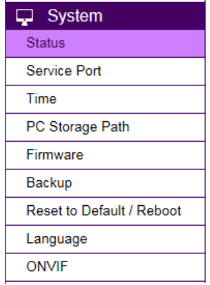
5.4. System
The System setting menu consists of system related configurations.
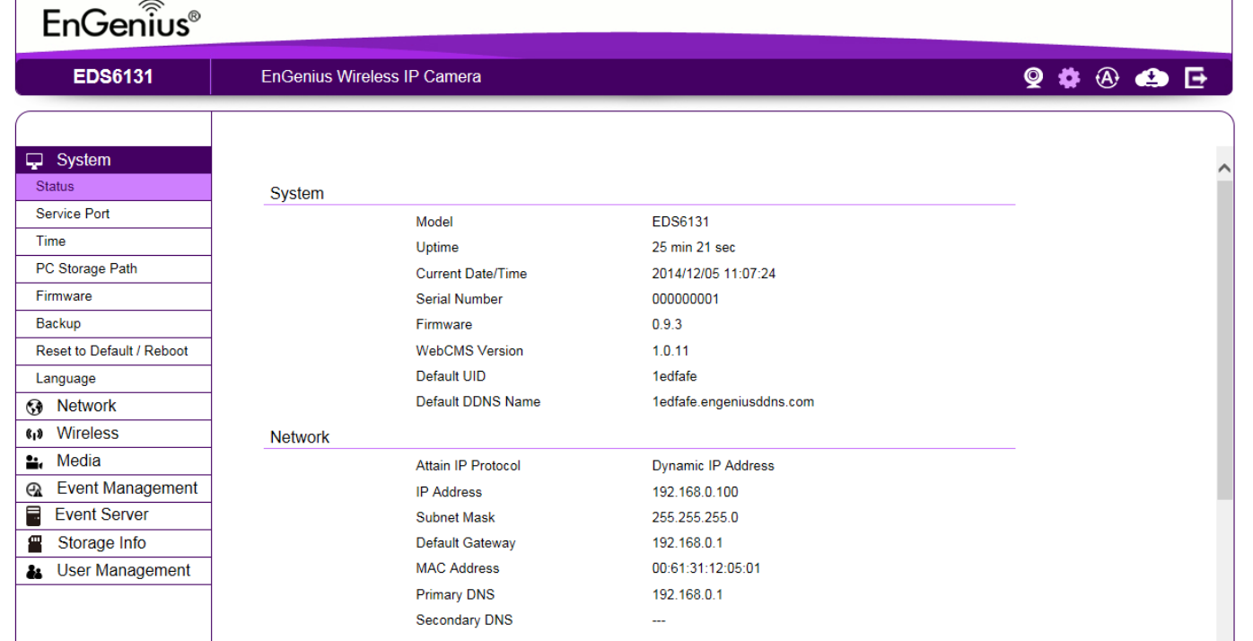
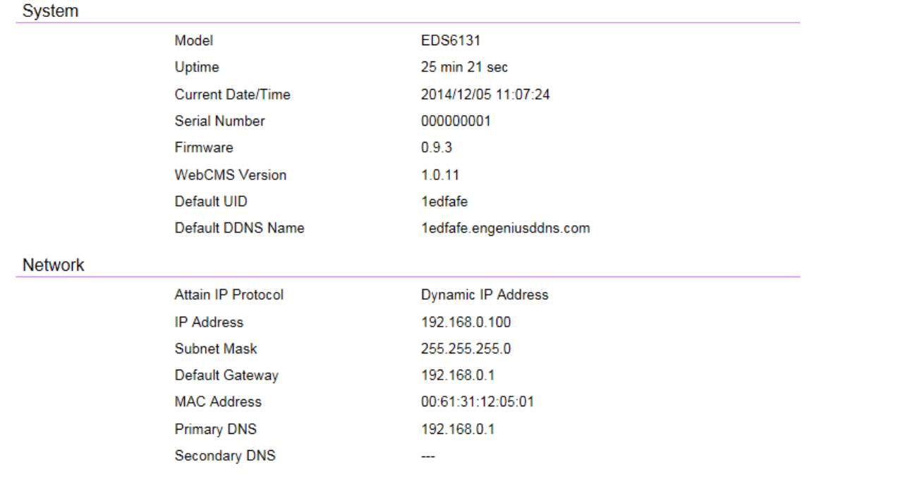
5.4.1. Status
Status Page displays the detail system level information on the page including current time, firmware version, DDNS name, IP address and etc.
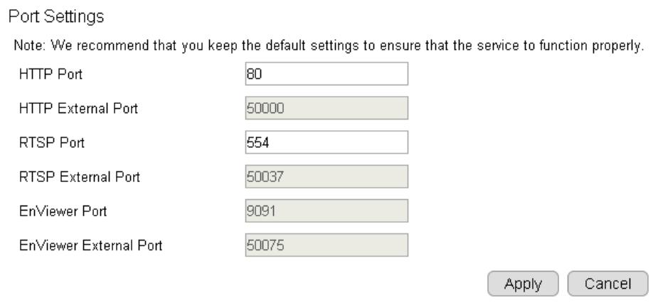
5.4.2. Service Port
The default setting is as follows. This is only reserved for advanced users who want to keep certain ports for other particular services.
Changing the ports will result in unexpected result. Unless necessary, please keep the default setting.
5.4.3. Time
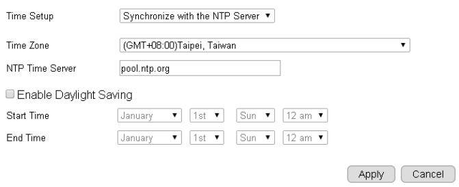
Like any other surveillance system, time is essential because we want to keep track of the time of the events recorded or detected by the
camera. By default, the camera is connected to a public time server (pool.ntp.org) and its time is always synchronized with the server over the
Internet. Normally, you only need to change the Time Zone. Choose the one that matches your location. Leave the other setting as default
should be fine. Setting the wrong time server or time zone will result in inaccurate scheduling and time stamp.
Time Setup: synchronized with time server or PC
Time Zone: select time zone
NTP Time Server: the time server address
Enable Daylight Saving: check the box if applicable
Start Time: The daylight saving start time
End Time: The daylight saving end time
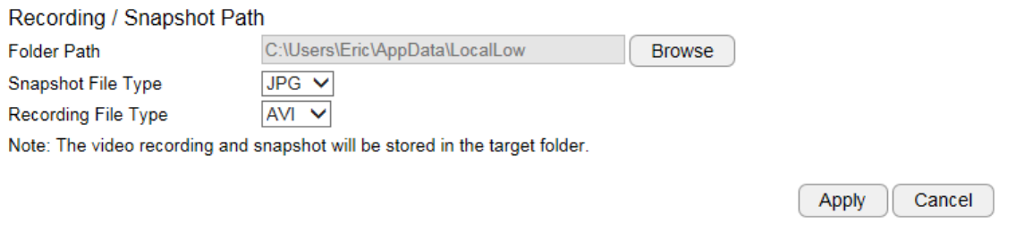
5.4.4. PC Storage Path
Folder Path: click “Browse” to change the path
Snapshot File Type: support image format JPG, PNG & BMP
Recording File Type: support format AVI & MP4
Compression rate comparison (High to Low):
JPG > PNG > BMP
MP4 > AVI
You should consider keeping the default setting because it reduces image or clip file size.
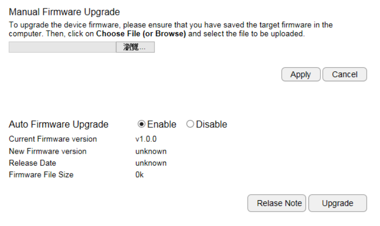
5.4.5. Firmware
The product feature may improve over time; you may check EnGenius official web site for the latest firmware. New firmware may contain
bug fixes or feature improvement which is beneficial to you.
Either download the latest firmware file to your local computer or use Auto Firmware Upgrade when Internet connection is available. For
manual upgrade, click Browse and select the firmware file to start upgrading firmware.
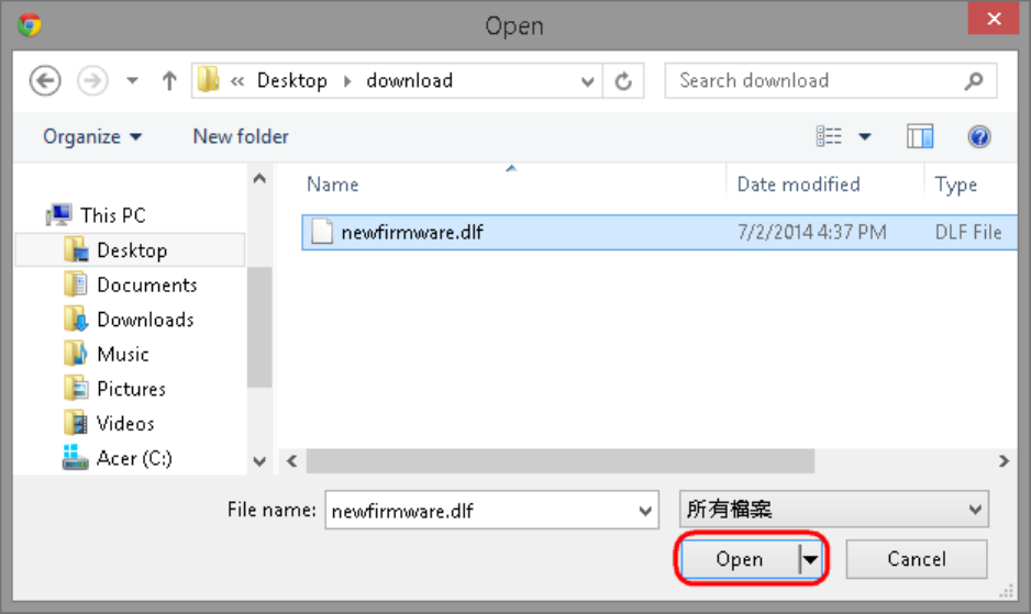
Select the downloaded new firmware then click on Open.
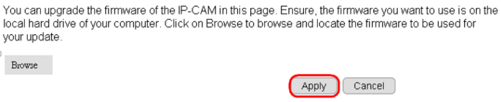
Click Apply to start upgrading the firmware.
It may take a moment for the upgrading process, please wait patiently.
WARNING: Do not turn off the device in the middle of upgrade process. Terminating the device during the process will damage the device and
may cause the device to fail.
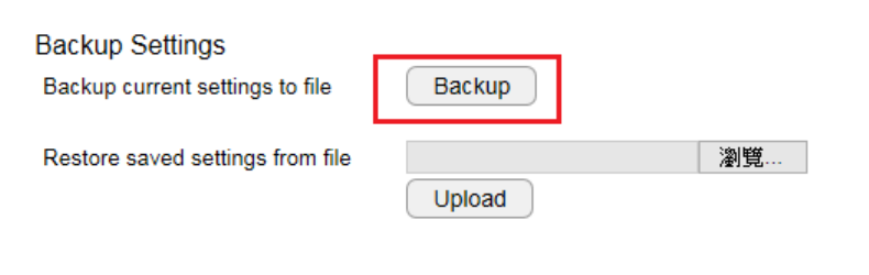
5.4.6. Back-up
There are times that you may want to test new settings or keep different settings for different application scenarios. You can do this with
following steps:
Save Settings
Click Save to initiate setting backup process.
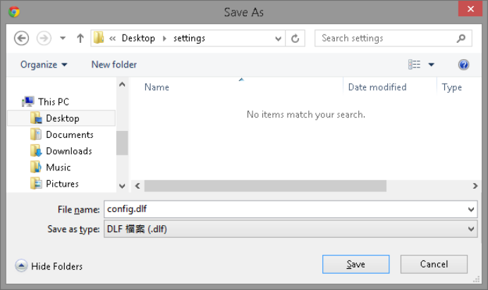
Click Save to store the file to the chosen location.
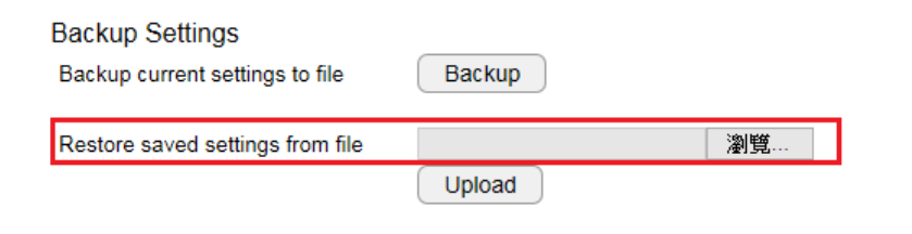
Restore Settings
Click on Browse to select the backup file.
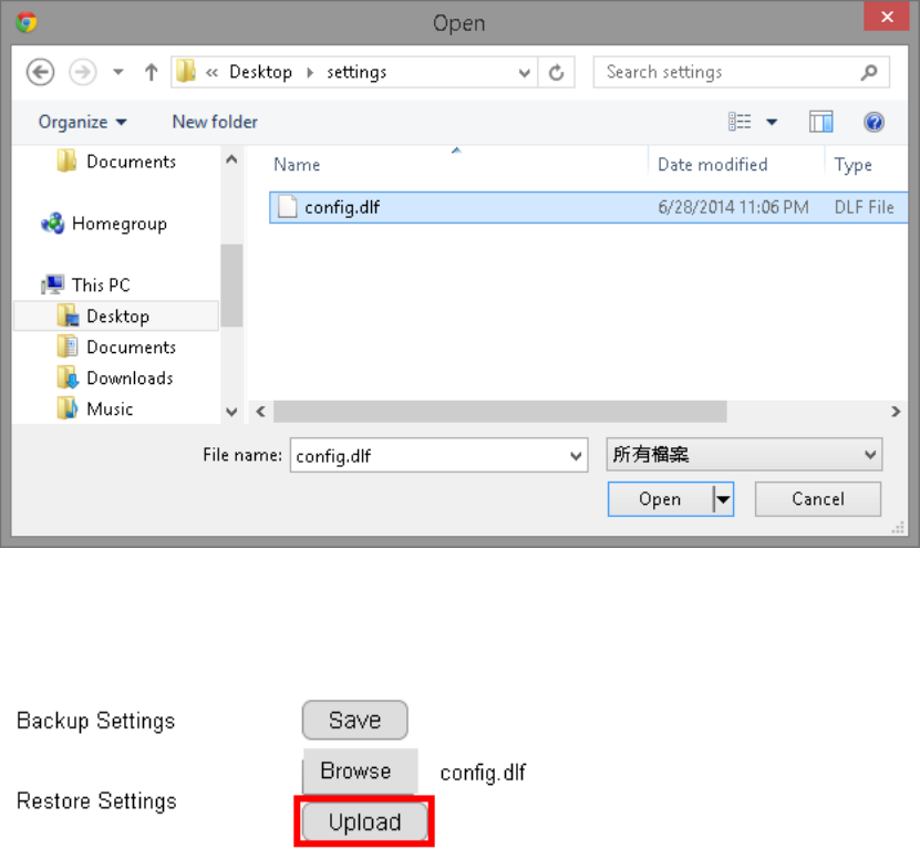
Choose the configuration file and click on Open.
Click on Upload to start storing process.
It may take a moment for the uploading process, please wait patiently.
WARNING: Do not turn off the device in the middle of the upload. Terminating the device during the process will damage the device and may
cause the device to fail.
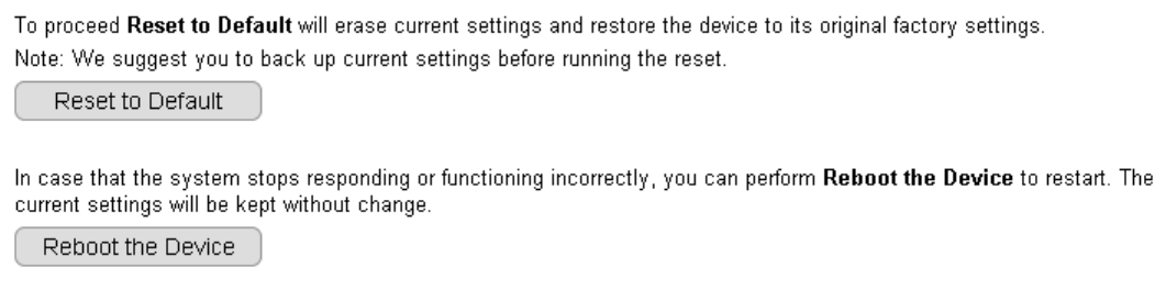
5.4.7. Reboot/Reset to Default
There may be times that you feel like to restore the settings to factory default. To reset to default click on the button Reset to Default
If the camera for some reason stop responding or acting abnormally, you can choose to Reboot the Device. If the device still does not recover
to normal operation, please consider to perform a hard reset (unplug and re-plug the power adapter).
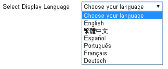
5.4.8. Language
The default User Interface language is English, you can change the language with just a mouse click.
On the language list, click to select the one you feel comfortable with from the list. The user interface with refresh automatically with your
chosen language.
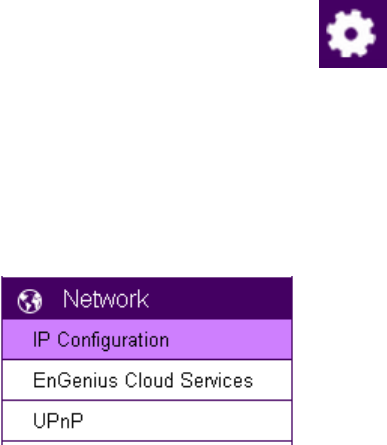
5.5. Network
The Network setting menu consists of Network related configurations.
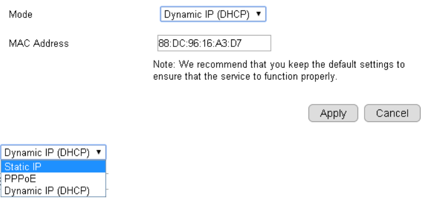
5.5.1. IP Configuration
Each camera should be assigned with an IP address in the network for identification. IP Configuration setting allows you to change the
method with which the camera obtains its IP address. The default setting Dynamic IP (DHCP) is applicable to most of the application scenario.
However, advanced users can also change to Static IP or PPPoE whichever suit the purpose.
Mode: Static IP, PPPoE and Dynamic IP (DHCP)
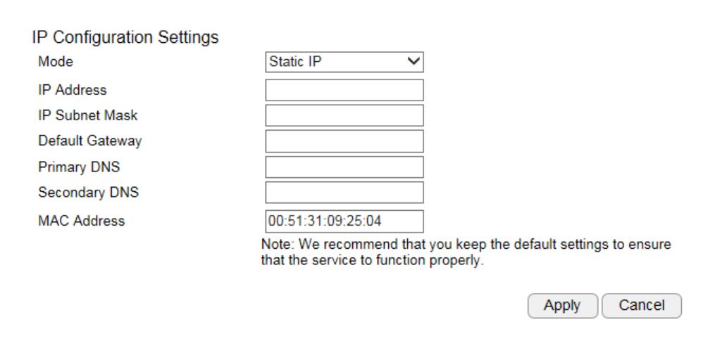
Static IP
If your network requires Static IP, you need to specify the detail IP settings similar to above. Please note that, if you are managing your camera
in local network similar to the example shown above, you will need to configure your management PC/Laptop under the same domain.
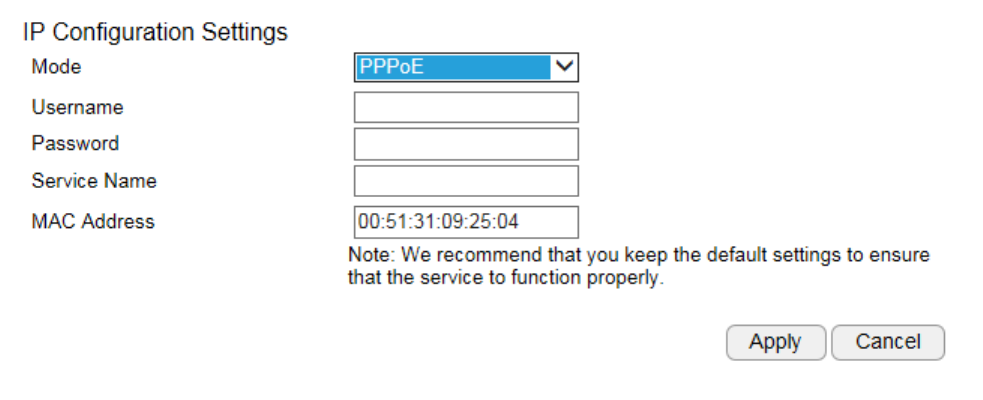
PPPoE
If you are connecting to the Internet without going through your home router, you can connect the camera directly to your modem (given
that you are using PPPoE for your Internet service). Please consult your local network service provider for more detail. Basically, the PPPoE
setting is exactly the same as what your home router. You need to provide at least Username and Password to get access.
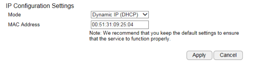
Dynamic IP (DHCP)
MAC Address: Type in the MAC address to insert the local MAC address into the field.
Click Apply when configuration is done to activate new settings.
Note: If you have a working Internet connection through your router, there is no need to type in the MAC address. Providing such MAC address
only if the IP address assigner binds each IP with a specific MAC address.
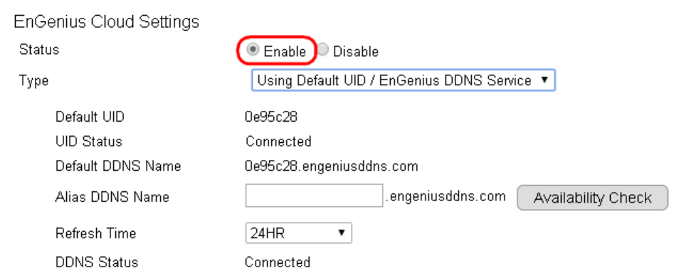
5.5.2. EnGenius Cloud Service
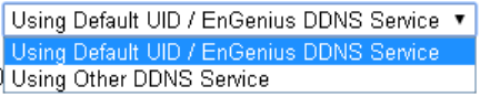
You must Enable EnGenius Cloud first and then choose the Type.
A key part about EnGenius Cloud Service is DDNS. Dynamic DNS (DDNS) is a type of DNS that works with dynamic IP address. DDNS
keeps update its mapping regularly and ensures a consistent matching so that your device can be accessed over the Internet using a fixed DDNS
name. You can either use the default EnGenius DDNS Service or other 3rd party Service you prefer.
Users are recommended to use the free DDNS address printed on the label enclosed in the package. This is because ISP often leases
dynamic WAN IP address that changes from time to time. DDNS domain name will always be the same even if the WAN IP address changes.
The domain name can also be found on your System Status page.
Default UID: default UID
UID Status: when working properly, it should show “Connected”.
Default DDNS: shows the default DDNS
Alias DDNS Name: You may find that your DDNS is too difficult to remember. EnGenius provides free DDNS name registration as long as the
alias is not yet been taken other EnGenius product users. You can check the availability by clicking on the button Availability Check for
verification. In this example, “superman.engeniusddns.com” is available. That is, when the setting is activated, both DDNS name
“superman.engeniusddns.com” and “0e95c28.engeniusddns.com” can be used to access this camera.
Refresh Time: options are 3HR, 6HR, 9HR, 12HR and 24HR. DDNS server needs to synchronize with your IP address often so that you can access
your device over the Internet with DDNS name. Depends on your Internet Service provider, your WAN IP address lease time will be different.
You can check with your local Internet Service provider for WAN IP address refresh time. The default setting is 24HR (which means DDNS server
will check the synchronization every 24 hours). Normally, the default setting 24HR is okay for most cases.
DDNS Status: when working properly, it should show “Connected”.
Note: DDNS will only work only if your router is connected to the Internet. If router is not connected to the Internet, your DDNS status will
show “Disconnected”.
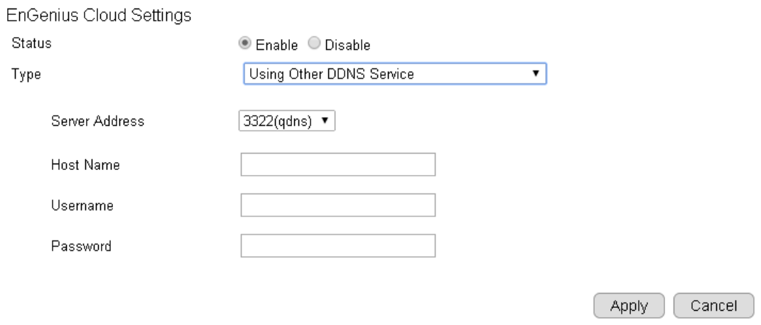
If you prefer to use third-party DDNS server, you can choose this option.
The current supported third-party DDNS services are 3322(qdns), DHS, DynDNS, ZoneEdit and CyberGate. Choose the one that best suits your
purpose. You should provide your account information so that the camera can communicate with the selected DDNS vendor.
Your third-party DDNS service account credential should include the following information.
Host Name: please enter your registered Host Name
Username: please enter your registered Username
Password: please enter the password for this
Click Apply when configuration is done to activate new settings.
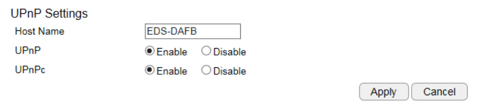
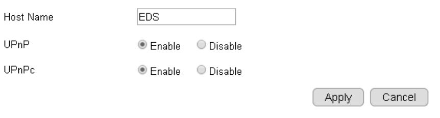
5.5.3. UPnP
Universal Plug and Play (UPnP) allows the other device to detect the presence of the camera so that communication become possible. You
should enable UPnP if you wish your camera to be recognized by your router. UPnP Traversal makes camera remote access over the Internet
possible using camera DDNS name. You won’t be able to access the camera if you disable UPnP feature. Please keep it Enable if you are not
sure.
Hostname: You may rename your camera to other meaningful names such as storage room, lobby, or any other descriptions you find suitable
to describe the space being monitored.
UPnP: Enable or Disable
UPnPc: Enable or Disable
Click Apply when configuration is done to activate new settings.
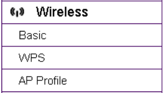
5.6. Wireless
All wireless related settings can be found under Wireless menu. The camera store several AP profiles (candidate AP list) although only one AP
will be connected at any given time.
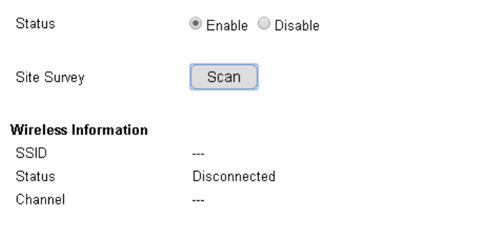
5.6.1. Basic
Under basic section, you can turn on or off the wireless radio, setting connection with the existing surrounding AP. Wireless Information shows
the current wireless status.
To setup a wireless connection, you must first enable wireless by choosing Enable option.
Click on Scan button to search for existing wireless access points (AP).
When prompted with Site Survey window, click on Refresh button if you do not find your AP on the list.
On the site list, choose your preferred AP and then click Add to AP Profile.
Then, on the AP Profile Settings window, please check if the security settings are correct. Please review the settings: Encryption, WPA type,
and Pre-Shared Key type. They are automatically detected. Normally, you only need to provide the Pre-Shared Key (password). However, you
can still change the settings if they do not match with the actually AP wireless security settings.
Enter your Pre-Shared Key and press Save to complete the setting.
Please wait for a moment for the setup to complete.
While waiting, you can remove RJ45 Ethernet Cable from the camera now. It may take a moment for the camera to establish wireless
connection with the chosen AP (your router).
Your camera should be connected to the AP now. You can verify it by login into your camera again. In case if the camera is still not accessible,
please check your AP’s wireless settings again to see whether your camera is connected.
5.6.2. WPS
Wi-Fi Protected Setup (WPS) is a network security standard that allows users to easily secure a wireless network. This feature allows user
to setup wireless connection between the camera and AP without entering any detail wireless security configurations such as SSID, encryption
method or pre-shared key (password). However, you need to initiate WPS process on both the camera and the AP at the same time so that
they can find each other.
Normally, for WPS-enabled products, you should be able to find the WPS button on the product. Only few rare cases that require user to
initiate WPS process over web page. Make sure WPS feature is Enabled on both the camera and your AP or wireless router. Then, you need to
know how to initiate AP or wireless router’s WPS process first. It is mostly likely a simple push of the WSP button on your AP or wireless router.
On EDS6115, you can initiate WPS process on the web page or by pressing the WPS button.
WPS Button
The simplest way to setup wireless connection with an AP or wireless router is by pressing on the WPS button.
First, press the WPS button on the AP (there may be changes on the LED lights as signs of initiation).
Then, press the WPS button of the camera.
Wait a minute for two devices to establish the wireless connection.
Done!
WPS over web page
You can initiate camera’s WPS process on the web page.
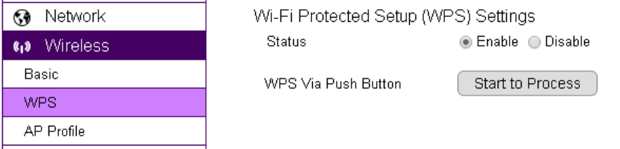
First, press the WPS button on the AP or wireless router (there may be changes on the LED lights as signs of initiation).
On camera’s WPS page, press Start to Process.
Wait a minute for two devices to establish the wireless connection.
Done!
NOTE: For WPS to setup wireless connection successfully, timing is essential. Once AP or wireless router has initiated WPS process, your camera
WPS process must be initiated within a given time range. It would be best if you have two devices in close range so that WPS process on both
sides can be initiated immediately after another.
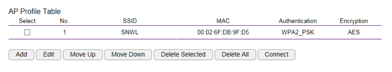
5.6.3. AP Profile
You can keep several AP Profiles (settings) if your application may need to switch between APs in case one of them failed. Each profile matches
to a specific AP.
5.6.3.1. Add
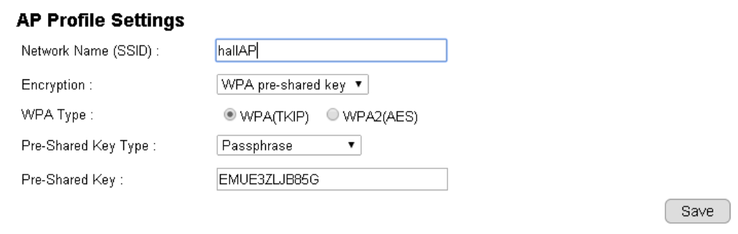
WPA pre-shared key
Network Name (SSID): enter the SSID of the target AP
Encryption: supports Disabled, WEP and WPA pre-shared key
WPA Type: supports WPA (TKIP) and WPS2(AES)
Pre-Shared Key Type: Passphrase or HEX (64 character)
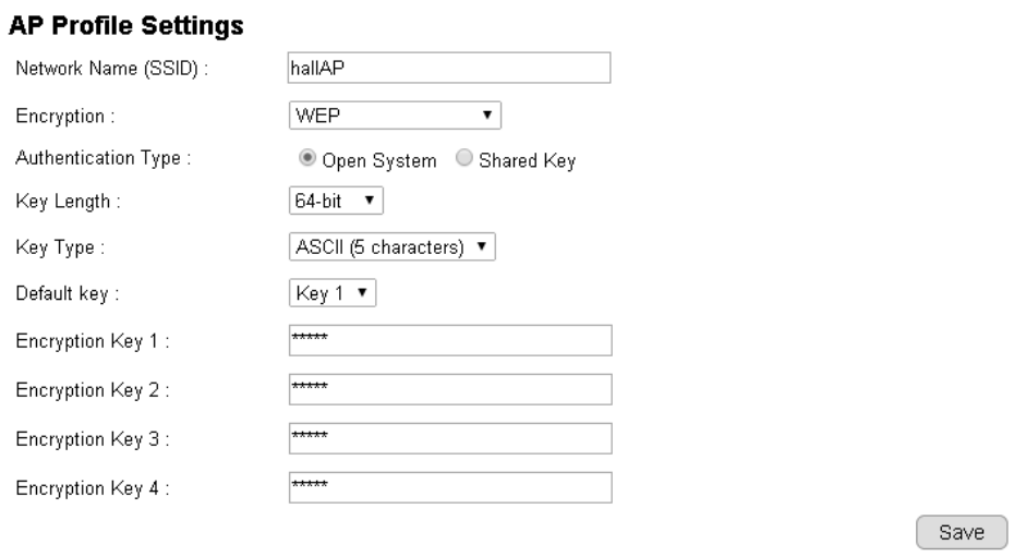
WEP
Please note that WEP has proven be insure, this security option is reserved only for legacy products that supports WEP only.
Authentication Type: supports Open System and Shared Key
Key Length: 64bit and 128bit (the longer the safer)
Key Type: ASCII or HEX
Default Key: the key that will be used for authentication
Encryption Key 1~4: the candidate keys for authentication
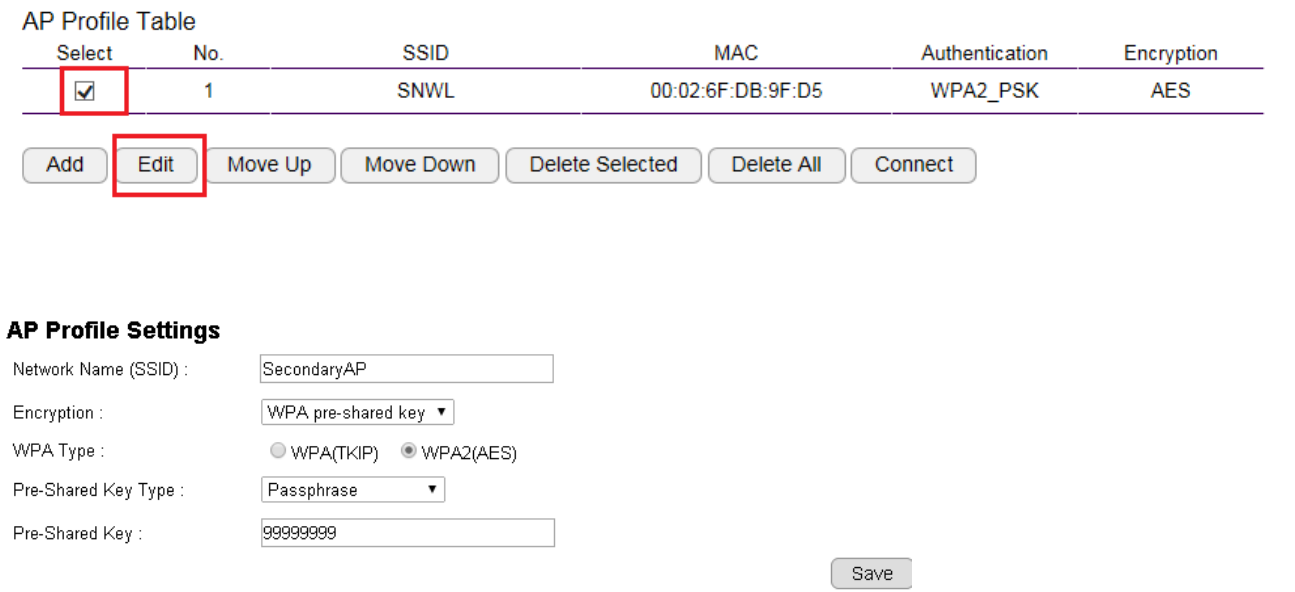
5.6.3.2. Edit
On the table Select the profile and then click on Edit to modify the profile setting.
Once complete the modification, click Save to make the changes effective.
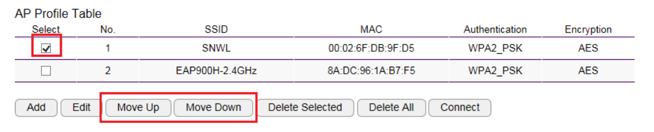
5.6.3.3. Move Up / Down
Each profile the ordered by the number at the front, the ones on top has higher priority when camera tries to search for the existing AP. You
can change the AP priority by moving them up or down. Select the profile and then click either on Move Up or Move Down.
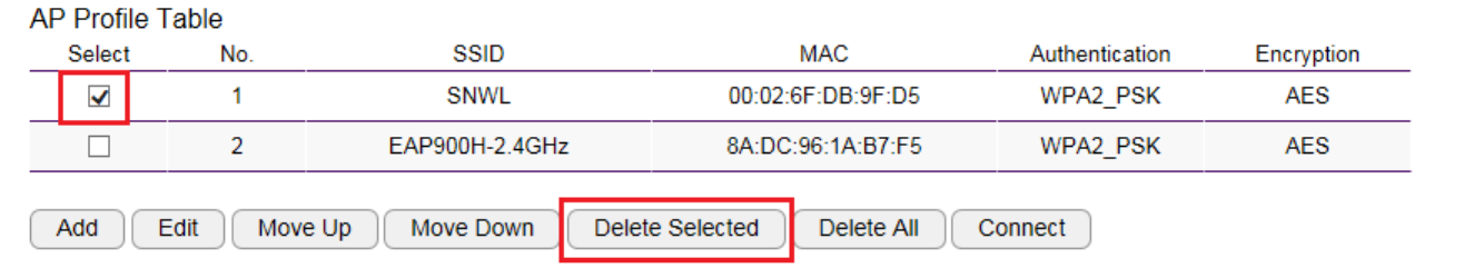
5.6.3.4. Delete
Delete Selected: only delete the selected profile.
Select the profile to be deleted and then click on Delete Selected button.
Delete All: this will delete all the AP profiles on the table
5.6.3.5. Connect
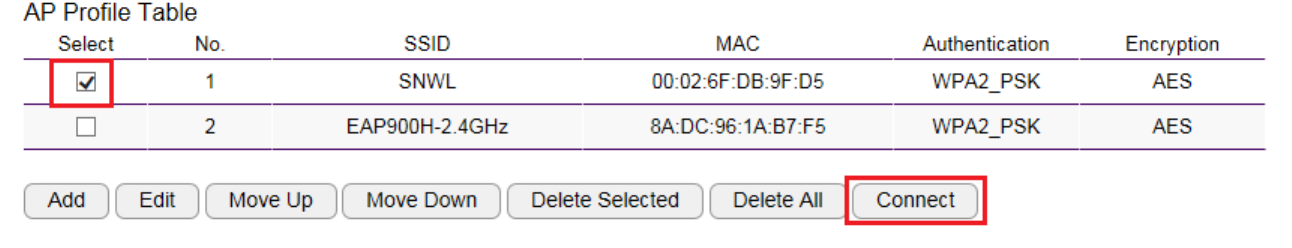
Select a profile to be connected and then click on Connect to initiate the wireless connection.
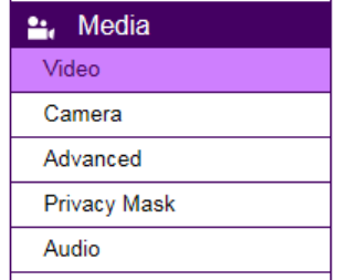
5.7. Media
All media quality related settings can be found under Media menu. These settings will have direct effect on the captured image or video.
5.7.1. Video

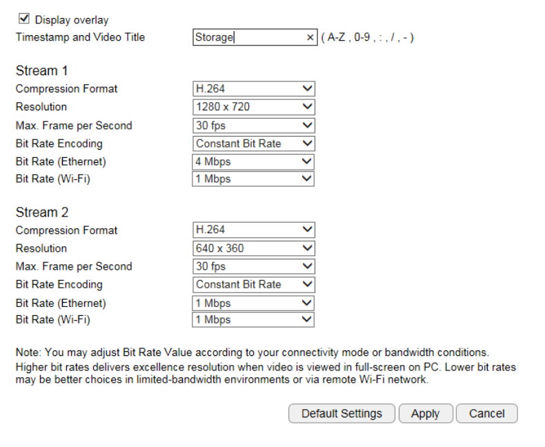
Enable: it is recommended that you enable Time Stamp and Video Title; the timestamp will show on the top-left corner of your video as
shown below.
5.7.2. Camera
You can get better quality by tuning the lighting condition of the camera. For example, in a dark room you may want to set the Brightness
higher to generate clearer result. When directly facing an outdoor window (too much light) you may want to lower the Brightness a bit. There
may be different settings under different circumstance; therefore, you should tune the setting if the image quality has become too low to serve
its purpose. Please refer to the following examples for comparison between low and high for each of the light settings.
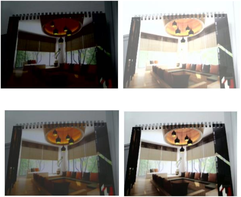
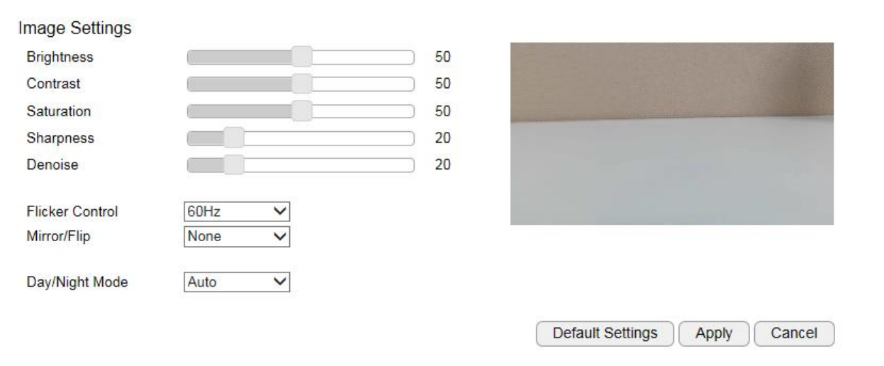
5.7.2.1. Light Setting
Brightness
Contrast
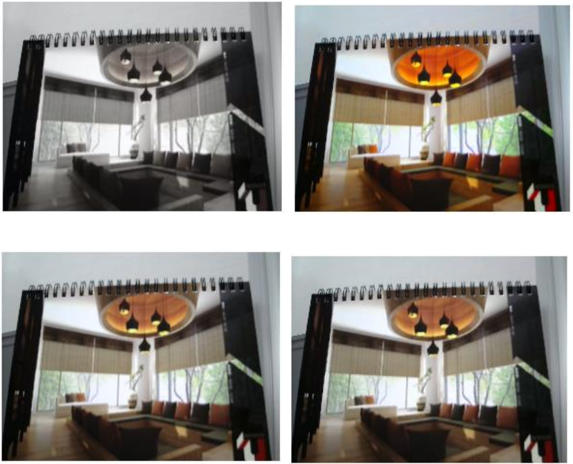
Sturation
Sharpness

De-noise
Please note that some of the effects will be more obvious in higher resolution at real time.
5.7.2.2. Flicker Control
The supported options are: 60Hz & 50Hz
Flicker Control is an anti-flicker feature setting.
AC lamp can cause a flicker effect, which is a consequence of the AC power frequency (50 or 60 Hz). As the light can change from picture
to picture, causing light flicker. This will lead to inconsistent light source between each snapshot. To eliminate flicker, configure your camera to
PAL (60Hz) or NTSC (50Hz) modes to compensate the effects. Check the power supply of your region for proper setting.
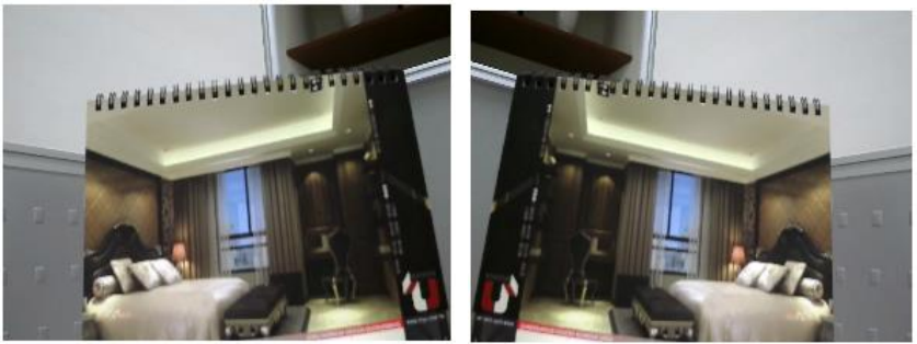
5.7.2.3. Mirror
Support Mirrors: None, Mirror, Flip and Both
There are times that the camera will have to be mounted upside down for sideways. That is, the view become difficult to monitor when it is
upside down. The Mirror settings does not reflect on the preview at real time (unlike lighting condition settings). Therefore, you have to click
on Apply to see the result.
The following examples compares none with a chosen mirror effect.
Mirror (Horizontal)
None Mirror
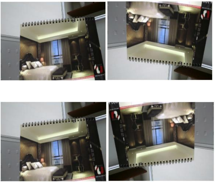
Flip (Vertical)
None Flip
Both (Horizontal and Vertical)
None Both
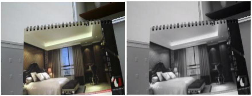
5.7.2.4. Day/Night Mode
This controls Night Vision ON and OFF.
Auto: auto detect light sufficiency and switch between Day and Night automatically.
Day: force the camera to turn OFF Night Vision.
Night: force the camera to turn Night Vision ON.
Day Night
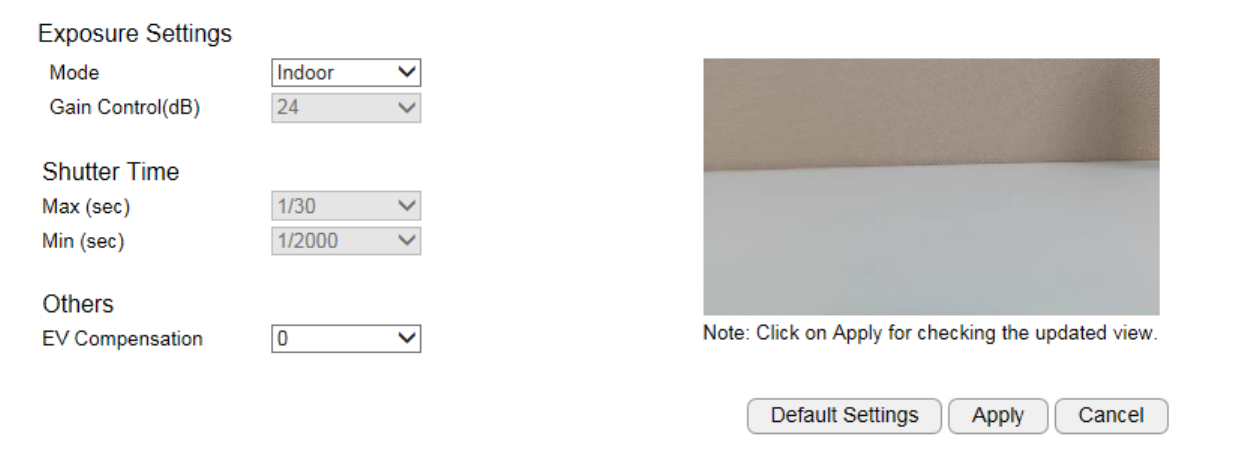
5.7.3. Advanced
Exposure Settings
Mode: Manual, Indoor, Outdoor
For regular users, please choose indoor or outdoor, the default values will the preconfigured. The areas are grey out for preconfigured settings
when you choose Indoor or Outdoor.
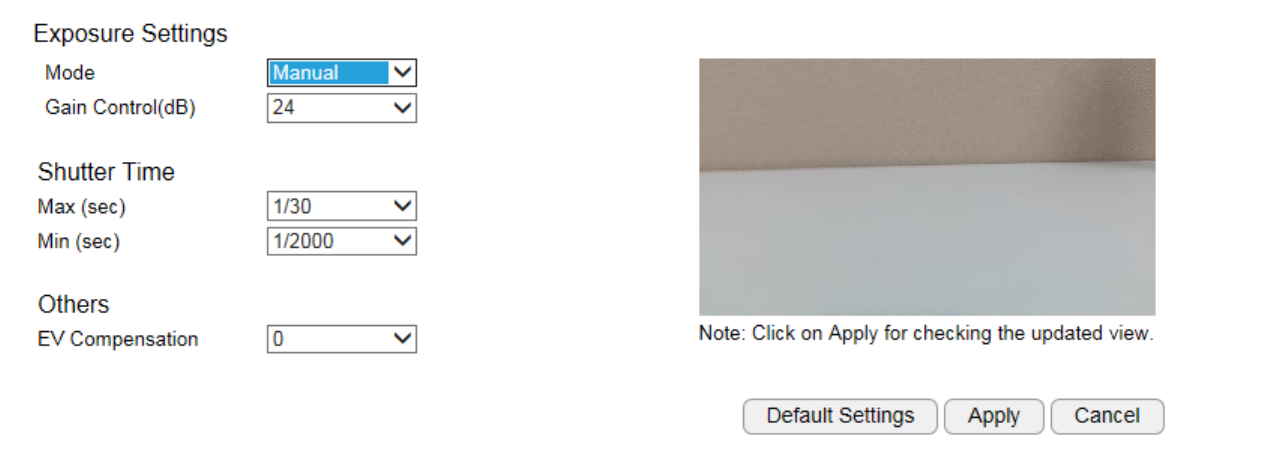
Manual
Choose Manual if you would like to fine tune some of the settings that suits your application. Please be noted that these settings may have
impacts on the image quality and performance. If you are not sure about the terms and behavior.
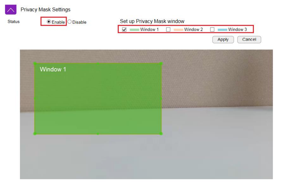
5.7.4. Privacy Mask
Choose Enable if you would like to put certain areas in private. Please use selected window to hide certain area for privacy purpose.
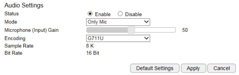
5.7.5. Audio
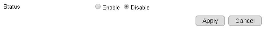
Status
If you audio is important to what you are monitoring, you need to set the audio status to Enable. So that the microphone can pick up sounds in
the environment. On the other hand, if audio is not necessary (for instance an open space with a lot of noises), you are advised to Disable the
audio to reduce the clips file size.
Mode
Only Mic: enable only the microphone
Input Gain: setting the sensitivity of the microphone. High gain will result in higher volume and but picks up more noise.
Encoding: supports G711A, AAC and G711U.
Sample Rate: 8 K
Bit Rate: 16 Bit
Changing Sample Rate and Bit Rate will impact the audio quality. The higher the rate, the better the quality and the larger the file will become.
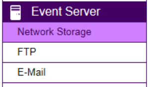
5.8. Event Server
It is required for users to configure Event Server settings before setting camera Event, Alarm or Schedule Recording. You will have to tell
where the captured images or clips are going to be stored. The following concept diagram depicts the flow of the image file when and when
captured. The file is stored at one of the predefine storage locations.
The simplest way to keep the media files is by local SD card; however, SD card storage size is relatively limited comparing to other
alternatives. On the other hand, Network Storage and FTP require you to have existing servers ready for upload. SMTP is good for small image
capture since it sends the file through email. You should choose what is best for your application.
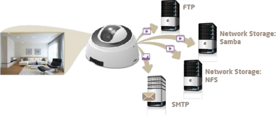
5.8.1. Network Storage
This camera supports two types of Network Storage: NFS and SAMBA.
Before going further, you need to Enable to configure the network storage first.
Please refer to the following sections for NFS and SMABA.
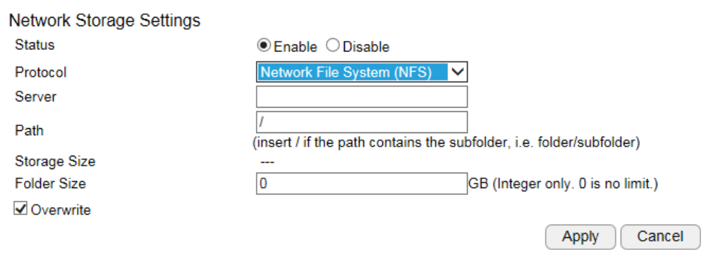
5.8.1.1. NFS (Network File System)
Server: IP address of the NFS server
Path: enter the initial path if applicable
Folder Size: storage allocated for the camera; the default value 0 signifies infinity.
Overwrite: when the defined folder is full, the oldest files will be overwritten to accommodate the new one.
Click Apply when done.
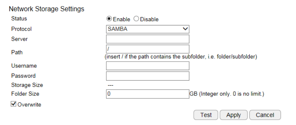
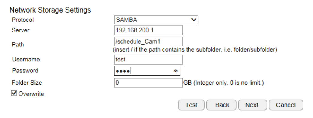
5.8.1.2. SAMBA
Server: IP address of the SAMBA server
Path: enter the initial path if applicable
User Name: username for accessing SAMBA server
Password: password for accessing SAMBA server
Folder Size: storage allocated for the camera; the default value 0 signifies infinity.
Overwrite: when the defined folder is full, the oldest files will be overwritten to accommodate the new one.
Click Test to verify the connection with the server using the username and password. Click Apply when done.
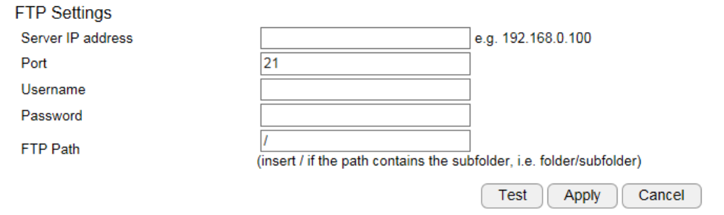
5.8.2. FTP (File Transfer Protocol)
Server: IP address of the FTP server
Port: the FTP server port; default 21
User Name: username for accessing FTP server
Password: password for accessing FTP server
FTP Path: enter the initial path if applicable
Click Test to verify the connection with the server using the username and password.
Click Apply when done.
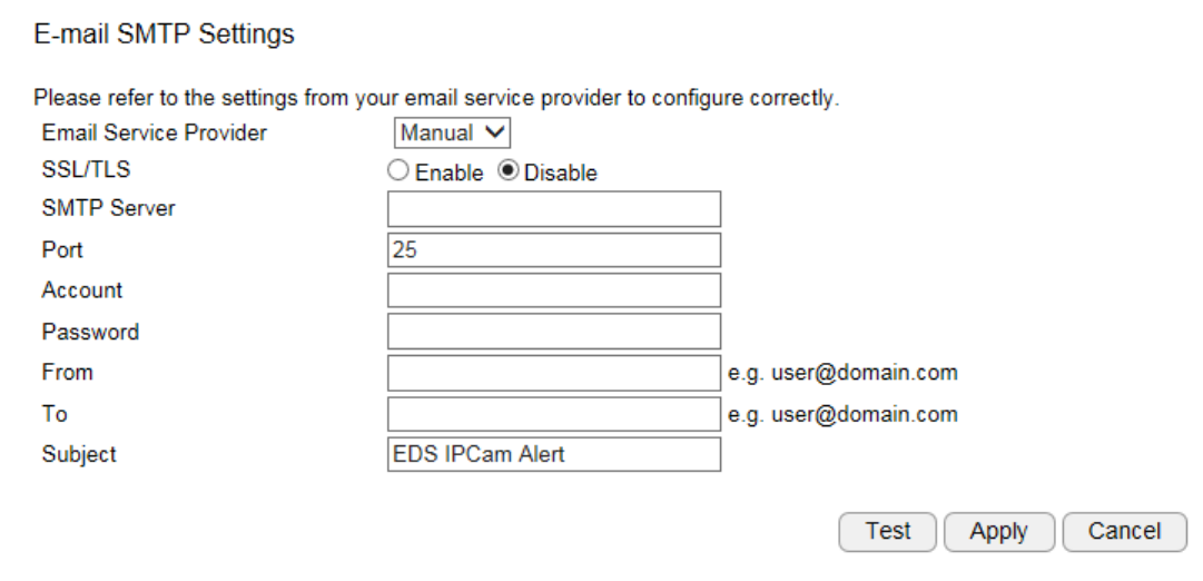
5.8.3. E-mail Alerts
EDS6115 allows camera to send captured images to the predefined email box to notify about an event or alarm.
SMTP is an email sender’s server. You need to check whether your email service provider supports SMTP and obtain the required information
for this setting.

Account: the email account name; if your email is myemail@gmail.com, myemail is the account name.
Password: the password you use to login into your email box.
Sender: you can type in your email address or other address if you would like the receiver to reply the email to.
SMTP Server: enter the SMTP server address (e.g. smtp.gmail.com).
Port: enter SMTP server port (normally 587 or 465)
Receiver: enter the receiver email here (usually your or the administrator’s email).
Subject: enter the email subject here.
5.8.4. SD Card
This camera supports MicroSD card slot. Please be careful when choosing the SD card type. You need to insert a blank SD card into the slot as
shown below. It may take a few seconds for the camera to recognize the inserted SD card.
You will be seeing the file list after inserted the SD card. If not, refresh the page by clicking on Refresh button and double check if the Micro SD
card has been properly inserted into the slot.
A default folder named snapshot is created automatically by the camera for storing the media files.
Dismount: you should dismount the SD card before physically removing it from the slot to avoid file damage.
Format: You can clean a SD card by formatting it (all data will be erased).
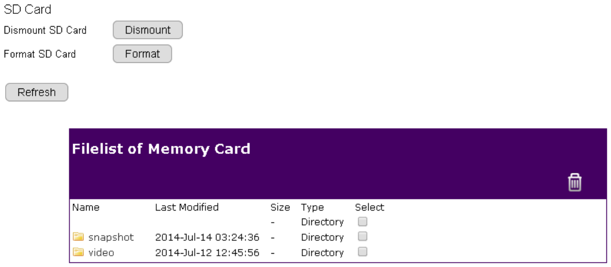
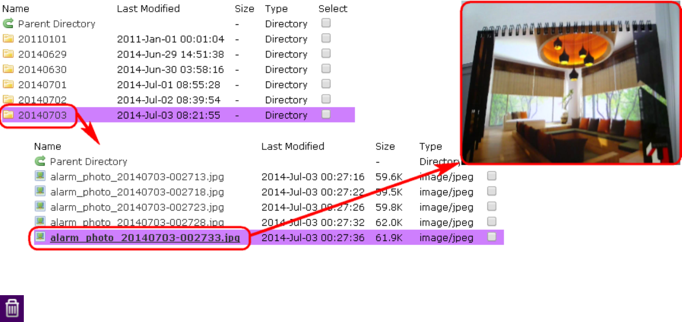
You can browse through the folder like any other file manager by clicking on the folder name.
Click on the files to view it directly as shown below.
Delete function: choose folder/file(s) and then click on the icon to REMOVE them from the SD card.
5.9. Event Management
This camera supports many smart features that allows you to utilize the camera in many application scenarios. This section will introduce each
of them in detail.
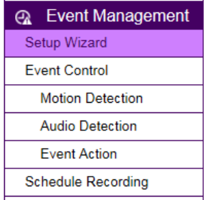
5.9.1. Setup Wizard
Wizard is an integrated configuration flow guide to the two main features on the camera: Event Control and Schedule Recording.
Event Control: When camera detects an event that matches the predefined condition an event will be triggered and proceed with the defined
actions; for instance, taking snapshots or recording videos for the specified length of time and interval.
Schedule Recording: Set the camera to record video regularly based on a predefined schedule.
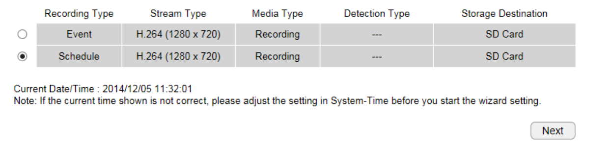
5.9.1.1. Wizard – Schedule Recording
Step 1: Select Schedule Recording
Choose Schedule Recording on the page and click Next to proceed.
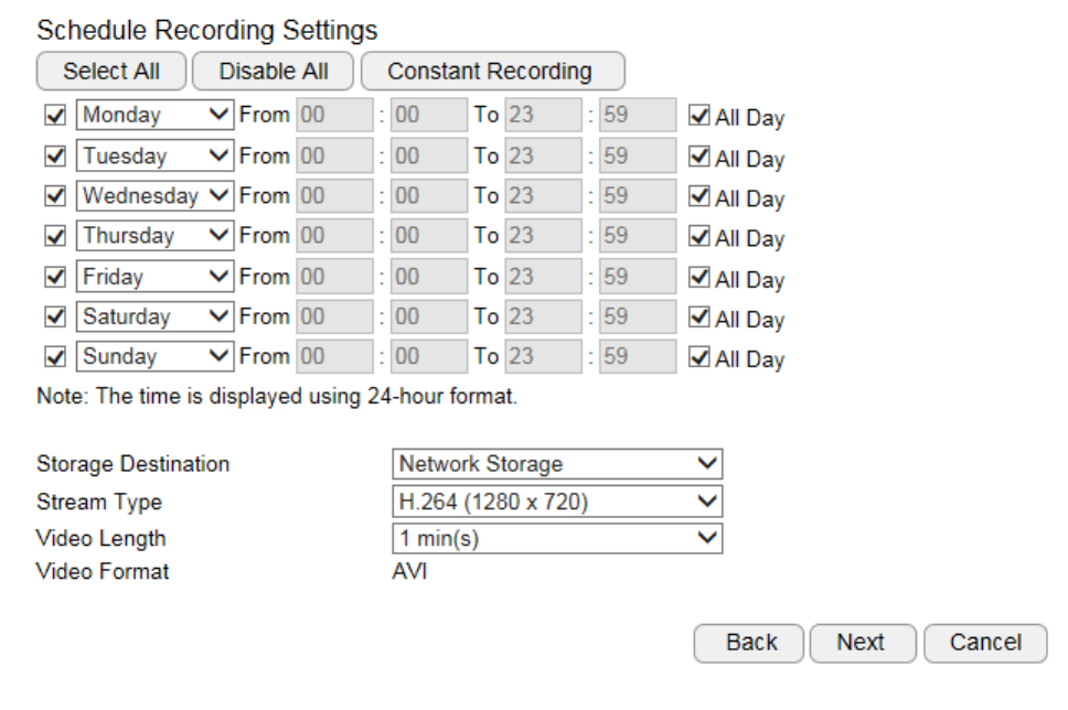
Step 2: Select Schedule Recording
Storage Destination: Network Storage (*Local SD card on certain models only)
Stream Type: H.264 (1280x720) or H.264 (640x360)
Video Interval: the maximum video length of time per file
File Format: AVI.
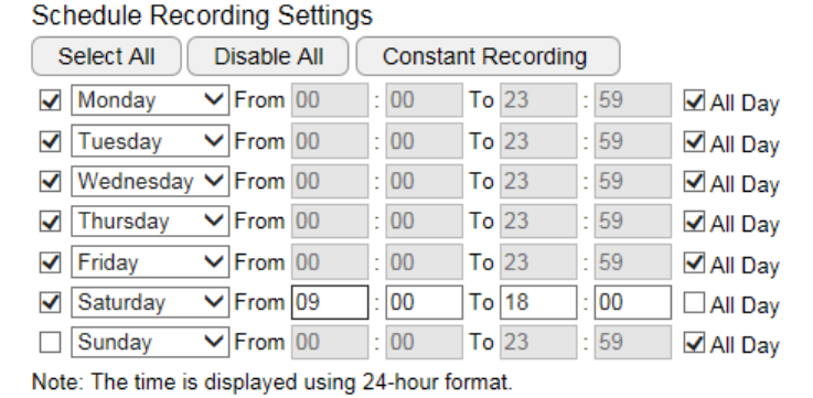
You can specify the time range for each schedule or simply click on All Day for 24-hours recording.
You must Select to enable the schedule.
Click Next when done.
Note: You may have two different schedules for the same day, e.g., Monday 08:00~12:00 and Monday 14:00 ~ 18:00.

Step 3: Network Storage Settings
Please provide all necessary info for Network Storage Settings; for management consideration, a different subfolder can be specified for each
camera.
Click Next to complete the wizard.
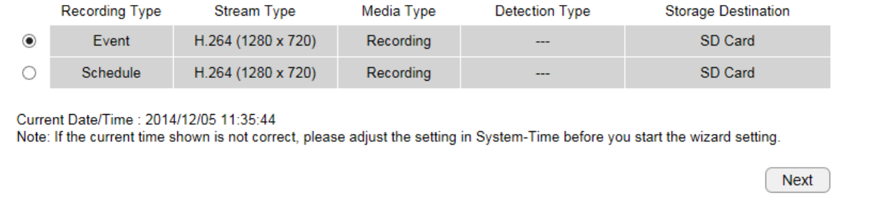
5.9.1.2. Wizard – Event
Step 1: Select Event
Choose Event on the page and click Next to proceed.
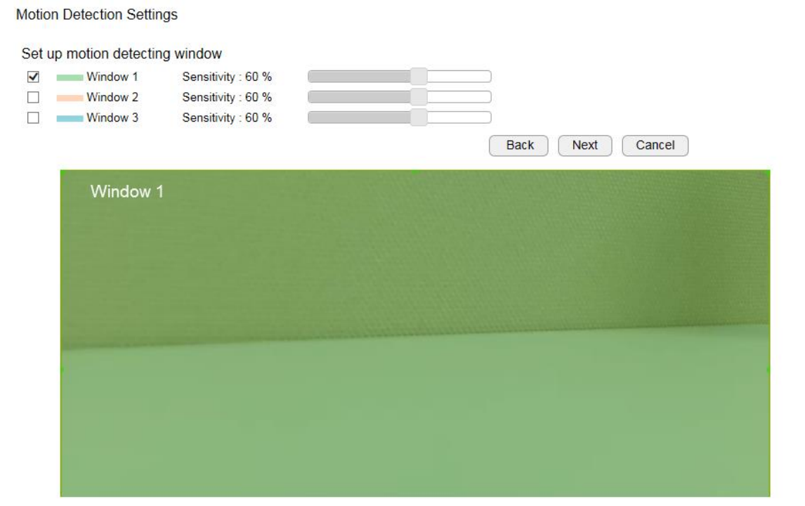
Step 2: Motion Detection Window Setting
Motion Detection Window is a hot zone that the camera analyzes for motion (image changes). When a motion is detected within the zone an
event will be triggered.
When the window is selected, use your mouse to move the window to the area you intend to monitor. There can be 3 windows at the most.
The Windows are differentiated by color; Window 1 is Green, Window 2 is Red and Window 3 is Blue.
Uncheck the window to remove the window from the view.
Sensitivity: Level 0% to Level 100% (with Level 100% being the most sensitive)
Depends on your application, high sensitivity will trigger event more often than low sensitivity and produce more snapshots or videos. However,
overly sensitive events will fill up the storage very quickly. Even if you have unlimited storage space, large amount of files can become a
problem when you need search through each of the files to find what you are really looking for. It may take some time for you to fine tune the
optimal sensitivity for your application.
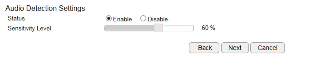
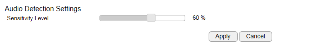
Step 3: Audio Detection Settings
Audio Detection is another way to trigger the event. You want the camera to initiate recording when there’s a sound in the background.
When the incidence falls out of the motion detection window, “sound” can be a good indication when a change in the environment has
occurred for attention.
Status: Enable or Disable
Sensitivity Level: 0% to 100% (with 100% being the most sensitive)
Similar to motion detection, high sensitivity will trigger events more often than low sensitivity and produce more snapshots or videos.
However, over-sensitive events will fill up the storage very quickly. Even if you have unlimited storage space, large amount of files can become a
problem when you need to search through each of the files to find what you are really looking for. It may take some time for you to fine tune
the optimal sensitivity for your application.
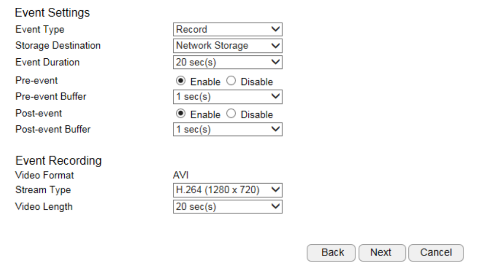
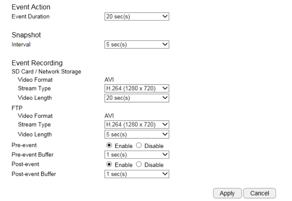
Step 4: Event Settings
Event Type: Record or Snapshot
Storage Destination: Network Storage (*SD Card only available on certain models)
Event Duration: the length of recording time when event is triggered.
Pre-event: Enable or Disable pre-event
Pre-event Buffer: the length of pre-event time (1~5 seconds)
Post-event: Enable or Disable post-event
Post-alarm Buffer: the length of post-event time (1~5 seconds)
File Format: the media file format.
Stream Type: H.264 (1280x720) or H.264 (640x360)
Video Length: the maximum video length of time per file
Note:
If setting Event Duration to 30 seconds, the camera will keep recording for 30 seconds when event is triggered. In this case, if the Video
Clip Size is 10 seconds, then 3 files will be generated for single instance of event. If Video Clip Size is 30 seconds, then only 1 file will be
generated. Please note that pre-event and post-event will extend the length of the clip for the chosen extra length of time.
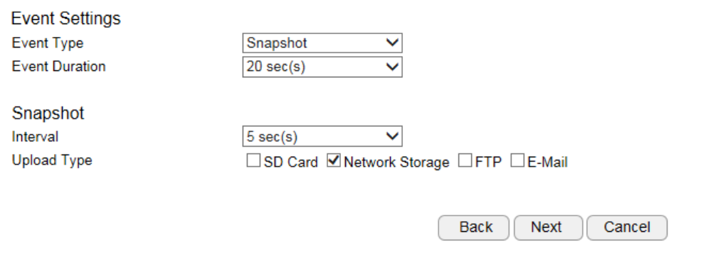
Event Method: Snapshot (images)
Event Duration: the length of recording time when event is triggered.
Interval: 5 seconds to 5 minutes (the elapse time between each snapshot)
Upload Type: method of storage.
Click Next when complete this step
Step 5: Network Storage Settings
Please provide all necessary info for Network Storage Settings; for management consideration, a different subfolder can be specified for each
camera.
Click Next to complete the wizard.
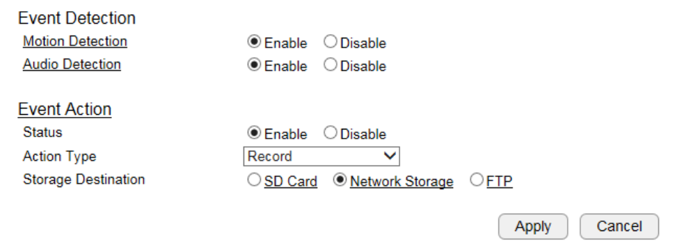
5.9.2. Event Control
You can choose event detection method and event action from this page.

5.9.2.1. Motion Detection

Motion Detection Window is a hot zone area that the camera analyzes for motion (image changes). When a motion is detected within the zone
an alarm will be triggered.
When the window is selected, use your mouse to move the window to the area you intend to monitor. There can be 3 windows at the most.
The Windows are differentiated by color; Window 1 is Green, Window 2 is Red and Window 3 is Blue.
Uncheck the window to remove the window from the view.
Sensitivity: Level 0% to Level 100% (with Level 100% being the most sensitive)
Depends on your application, high sensitivity will trigger event more often than low sensitivity and produce more snapshots or videos. However,
overly sensitive events will fill up the storage very quickly. Even if you have unlimited storage space, large amount of files can become a
problem when you need search through each of the files to find what you are really looking for. It may take some time for you to fine tune the
optimal sensitivity for your application.
You can adjust the motion detecting area by dragging the four corners to resize the window.
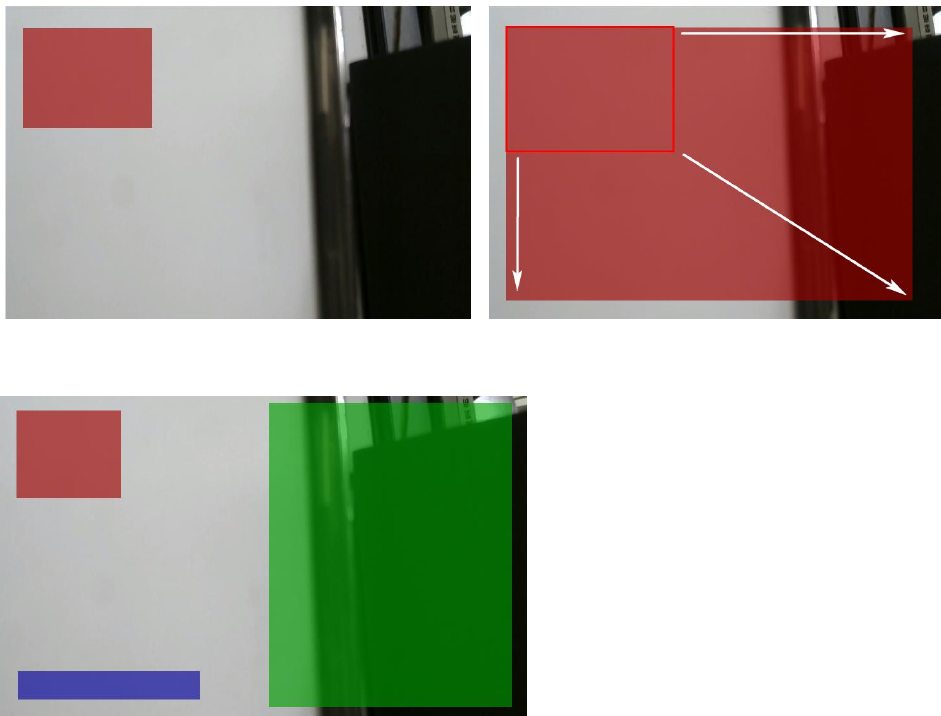
Therefore, you can have a combination of three different detection window sizes.
5.9.2.2. Audio Detection
Sensitivity Level: 0% to 100% (with 100% being the most sensitive)
Similar to motion detection, high sensitivity will trigger events more often than low sensitivity and produce more snapshots or videos.
However, over-sensitive events will fill up the storage very quickly. Even if you have unlimited storage space, large amount of files can become a
problem when you need to search through each of the files to find what you are really looking for. It may take some time for you to fine tune
the optimal sensitivity for your application.
5.9.2.3. Event Action
This page provides Event-related settings (briefed in earlier Wizard sections).
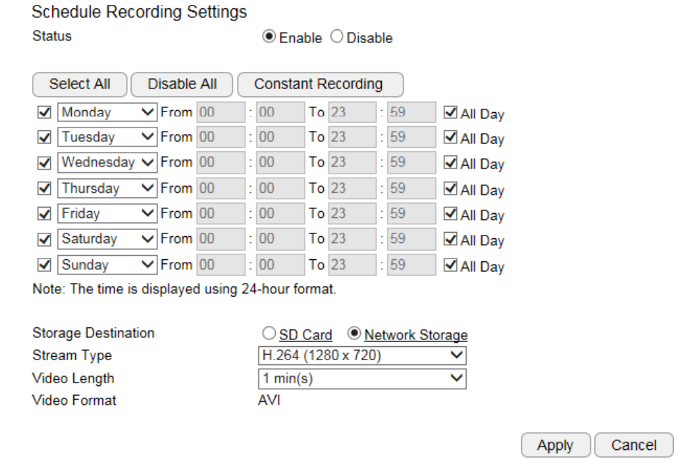
5.9.3. Schedule Recording
Storage Destination: Network Storage (*Local SD card on certain models only)
Stream Type: H.264 (1280x720) or H.264 (640x360)
Video Interval: the maximum video length of time per file
File Format: AVI.
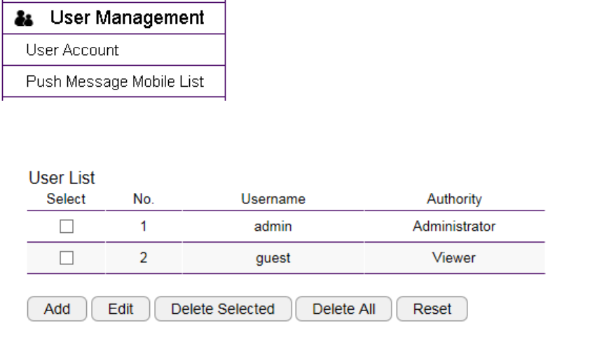
5.10. User Management
There are two types of user accounts: Administrator and Viewer. Administrator has full control over the camera settings while viewer only
has the accessibility of watching the real time video. Viewer account is particularly useful when you have multiple users such as other staff
members. You may have many administrators as well as viewers depending on your needs.
Administrator has full control of the camera interface with configuration features as shown below.
Viewer only has basic camera view interface.
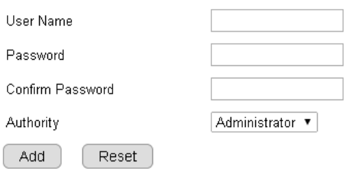
5.10.1. Add User
User Name: enter username
Password: enter password
Confirm Password: enter password for confirmation
Authority: select Administrator or Viewer
Click Add to add the user
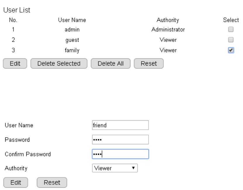
5.10.2. Edit User
Select a user from the list by click on the check box.
Click Edit to change the user account setting.
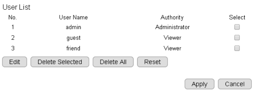
Make the changes and then click Edit to save the changes.
Once all necessary changes are made to the accounts, click Apply to make the changes affective.
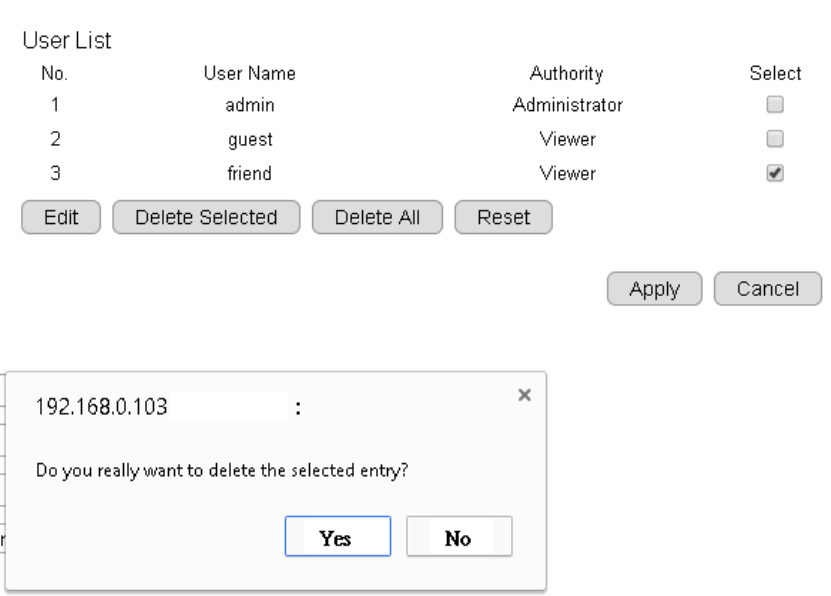
5.10.3. Delete User
On the user list, select the user account to be deleted.
Click on Delete Selected to delete the account.
When prompted with delete confirmation, click Yes to delete.
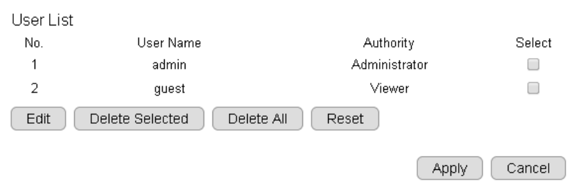
Once all necessary changes are made to the accounts, click Apply to make the changes affective.
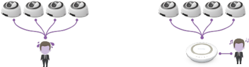
6. Camera Connecting to EnGenius Router
Smart Recording is an intelligent camera management technology that allows EnGenius users to manage cameras collectively with ease.
EnGenius bundles cameras with Intelligent Router and IoT gateway series and provides a single point of entrance for integrated management.
Traditionally, if you have multiple cameras installed you will need to go through the tedious configurations on each of the camera. The benefits
of Smart Recording are as follows:
1. Easy and Integrated Access
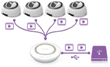
2. Integrated Storage
Smart Recording technology integrates the EnGenius Intelligent Router and IoT Gateway storage feature and allows you to store the media
files on the centralized storage over the router.
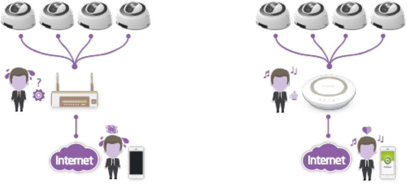
3. Easy Remote Access over Internet
Traditionally, you cannot get access to your Camera over the Internet without some manual configuration known as Port Forwarding
because your camera is installed under a local network. Smart Recording technology takes care of all the complicated setup and leave you with
ease of control. That is, you will be able to access any of the cameras in your home by providing their DDNS names on EnViewer or web
browser if you are using PC/Laptop.
6.1. Enable Router Storage Function
The best thing about Smart Recording is that you can make use of the EnGenius Router Storage function. You should attach an external USB
storage device (portable hard-disk or USB flash drive) to your router. Enter the Username and Password of your router and press Login.
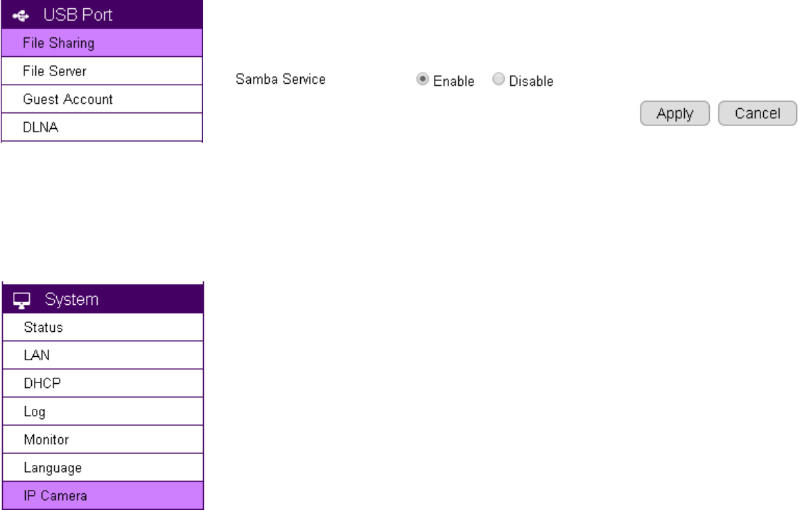
If you have not yet enable Samba Server on your router, choose USB Port File Sharing. Skip this step if samba is already enabled. Then,
Enable Samba Service and click on Apply to activate the function.
On your router’s Main Menu, Click System IP Camera to access the connected cameras.
Note: that only EnGenius Cameras can be managed collectively by EnGenius Router. For other vendor’s cameras, you still have to configure
them one by one manually.
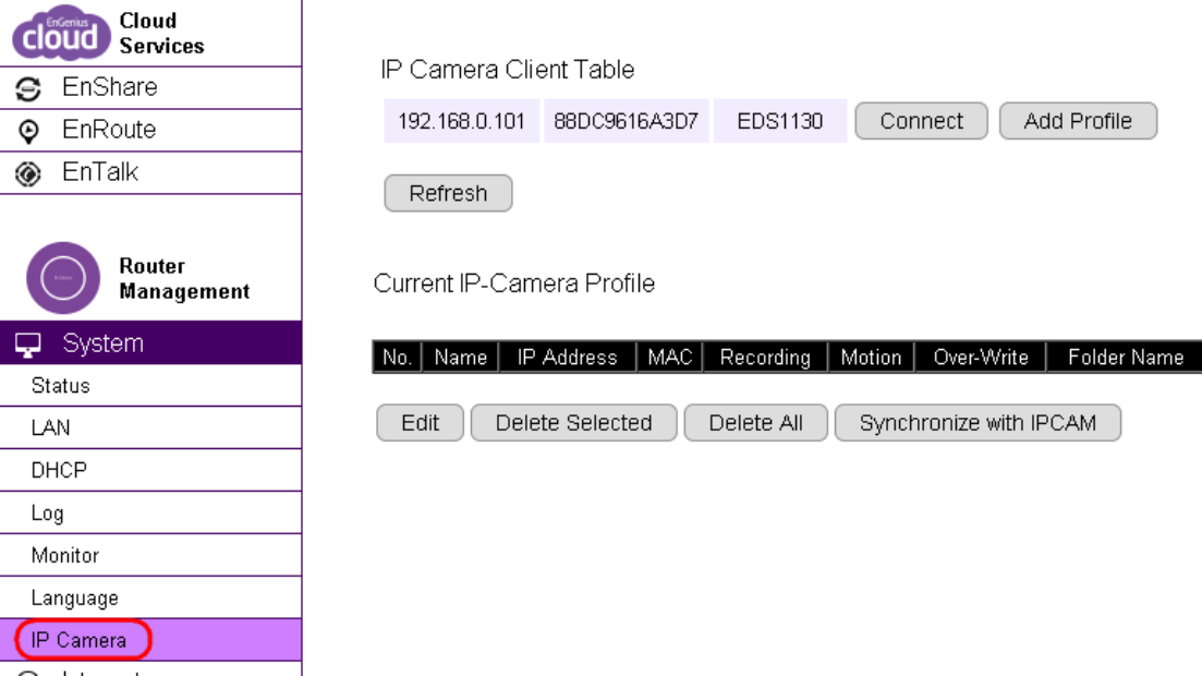
You should be see all your cameras listed on the IP Camera Client Table. If not, click Refresh button to scan the network again.
Please be noted that only EnGenius Cameras will be listed on the table.
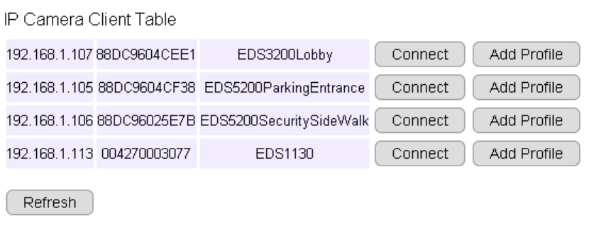
Connect: You can get access to the selected cameras’ camera mange page.
Add Profile: Add the selected camera to a profile (please refer to next section for more detail on Profile)
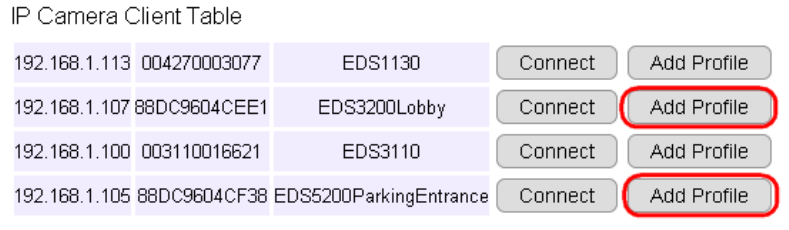
6.2. Camera Profile
A Profile is an entry that represents the added camera. You must add the camera to a profile so that the router has the privilege to
configure your camera and link them together.
6.2.1. Add Profile
This example shows 4 connecting cameras on the router. We have chosen to add two cameras (Lobby and Entrance) for demonstration
purpose.
Click on Add Profile button to add the chosen camera.
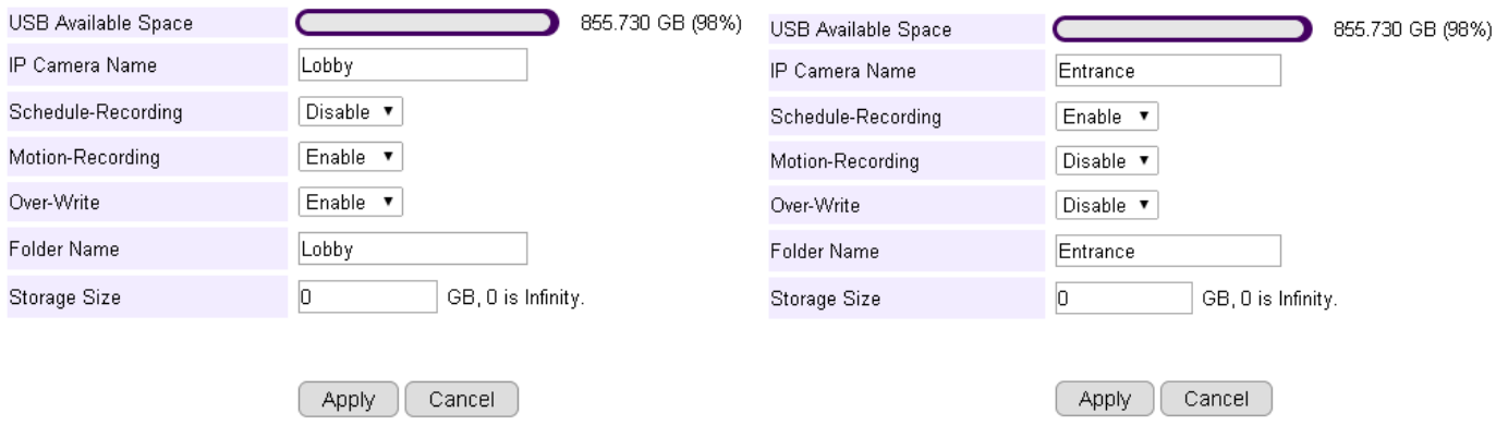
IP Camera Name: Lobby (use meaningful name for better identification)
Scheduled-Recording: Enable/Disable this type of recording
Motion-Recording: Enable/Disable this type of recording
Over-Write: Enable/Disable over-writing the old files when there’s no space for storing the new files
Folder Name: The name of the folder where the media files of this camera will be stored on the router storage.
Storage Size: put 0 if storage is unlimited.
Click Apply when done.

The added cameras will be listed as shown below.
You can Edit or Delete profile by selecting the profile and click on the buttons below.

6.2.2. Edit Profile
Select the camera profile and then click Edit button to make the changes.

6.2.3. Delete Profile
Select the camera profile and then click Delete Selected button to delete the profile.
Click Delete All to delete all the profiles.
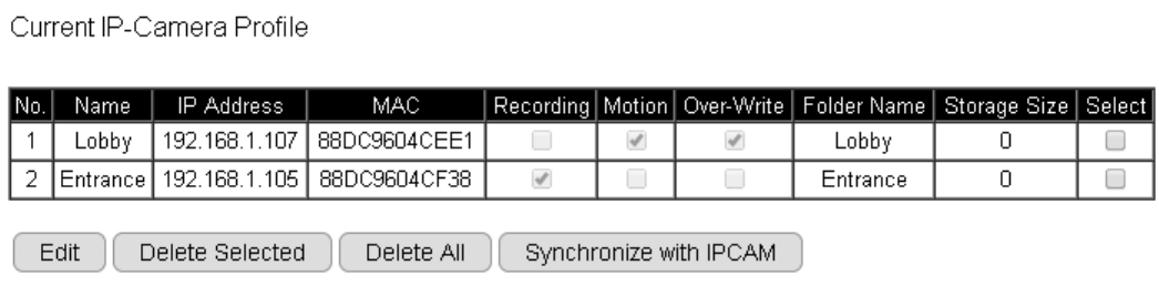
6.2.4. Synchronize
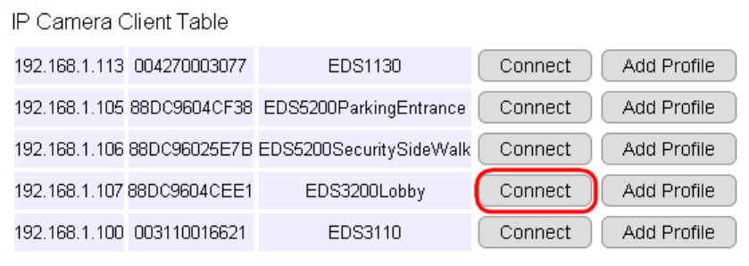
6.3. Fine Tune Camera Configuration set by the Router
This section provides extra information on what actually happened to your camera’s setting after you added it to the Profile on the router.
It is helpful for you to go through the automatically configured camera settings and make proper changes when necessary.
Click on Connect button to open the chosen camera’s login page.
6.3.1. Camera Storage Setting
Then go to Storage Network Storage section.
As you can see shown below, the camera storage is automatically configured for you. These settings enable your camera to store media files
on the router storage. Each camera will be given different Path so that you can search for the associated files easily.
In the previous example, we have named the camera profile as Lobby; therefore, the Path given to this camera is /sda1/IP_Camera/Lobby.
Please do not change the settings because it only works if the setting matches the connected router.
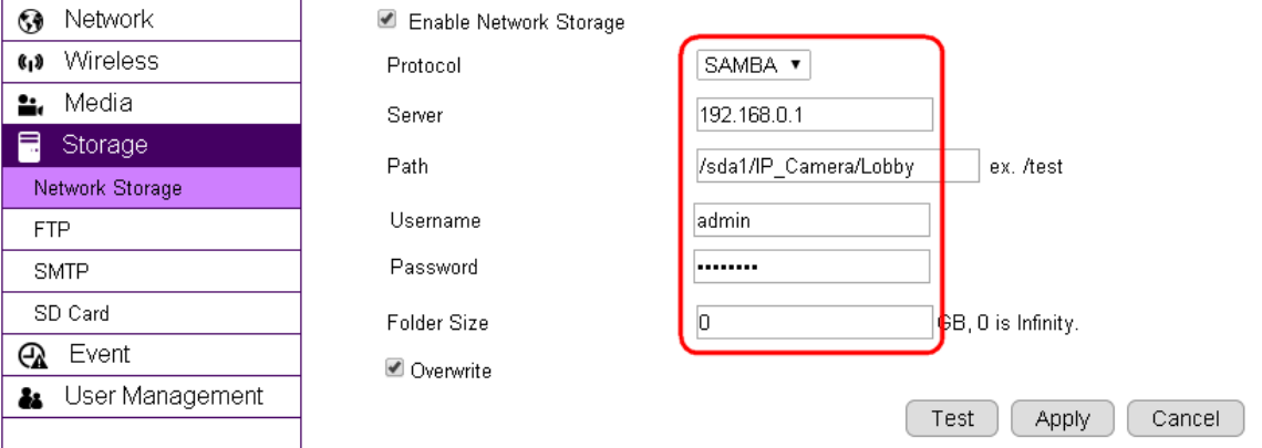
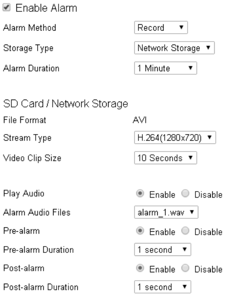
6.3.2. Camera Event Setting
The router configured the camera with default Alarm Method: Record. If can make necessary changes if necessary. For instance, you may want
to change Record to Snapshot if static pictures are preferable in your application.
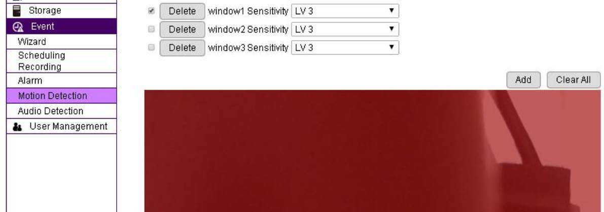
6.3.3. Camera Motion Detection Setting
In the previous section, the Lobby profile is configured with Motion-Detection enabled. Therefore, the router configured the camera with a full
screen motion detection window. You may change the motion detection region if necessary.
6.4. Access the Media files on the Router
6.4.1. Using web browser
Please refer to EnGenius Router user’s manual for more detail on the Shared Storage feature.
You can click on USB Port icon to access the storage.
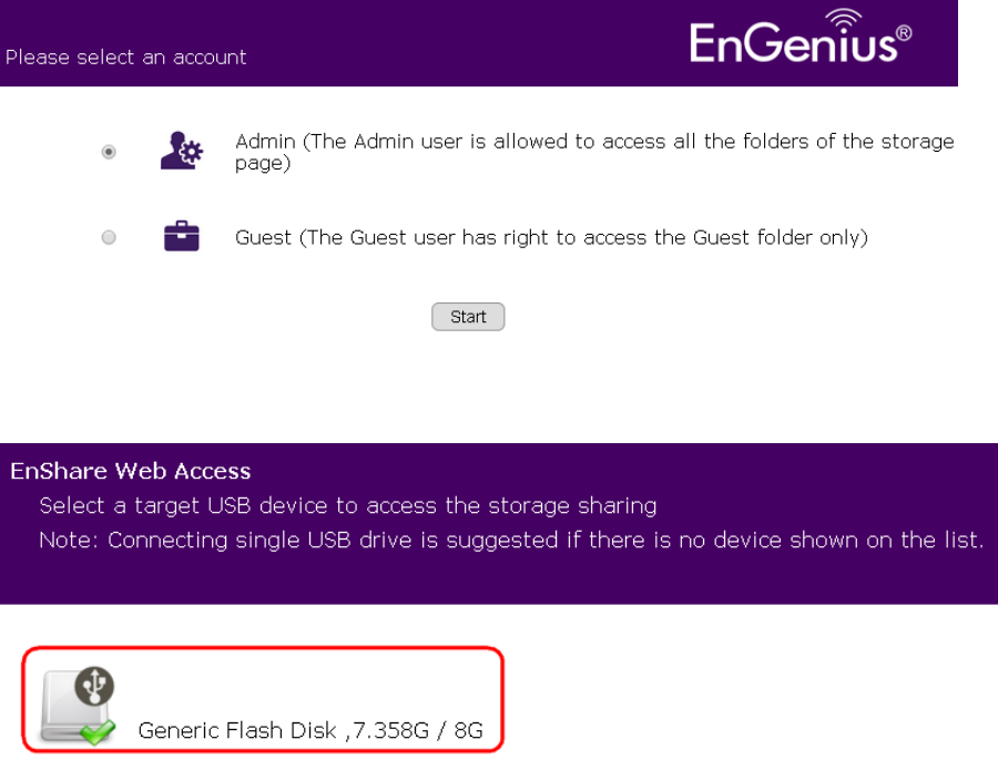
Choose Admin and click on Start button.
Choose the storage device to access the file.
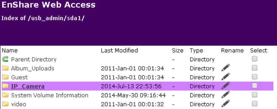
In the previous example, the Lobby camera profile defines the path /sda1/IP_Camera/Lobby/
The media files will be stored as shown below.
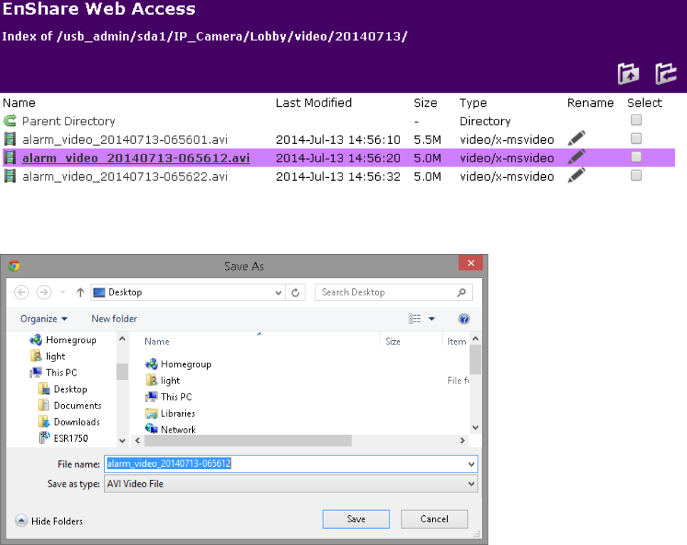
Click the file to download it.
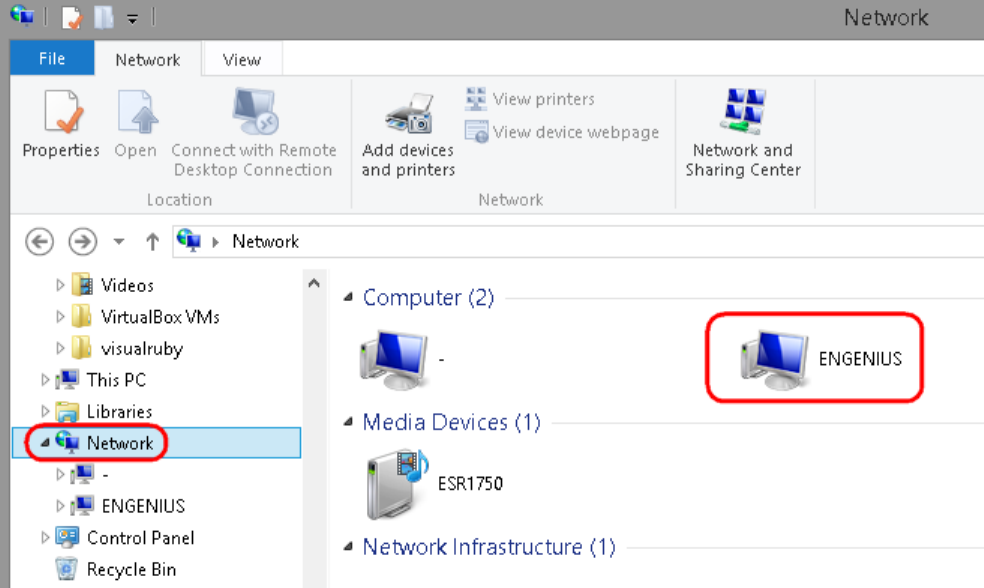
6.4.2. Using Windows File Explorer
Once enabled Samba on the EnGenius router, you should find the router under Network in your File Explorer as shown above.
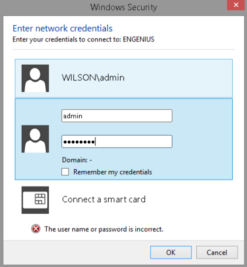
Double click on ENGENIUS to get access to the storage space.
Upon security prompt, enter the router’s username and password to continue.
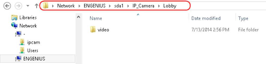
You can access the media files located under \\ENGENIUS\sda1\IP_Camera\Lobby
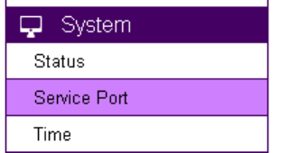
7. Camera Connecting to Other Router
Normally, you do not need to make any changes to your router setting to be able to use the camera. However, in case if you experience issues
in connecting the camera, you should probably check for the following settings. UPnP, UPnP Traversal and Firewall.
UPnP and UPnP Traversal:
Universal Plug and Play (UPnP) allows the other device to detect the presence of the camera so that communication become possible.
Please ensure that your router supports UPnP Traversal and has it enabled. Most of the modern wireless router today supports this feature. You
should enable UPnP if you wish your camera to be recognized by the home router. If you can’t find the related settings, they are most likely
enabled by default. UPnP Traversal makes camera remote access over the Internet possible using camera DDNS name.
Firewall:
By default, the firewall function of the router is not configured to filter out specific traffic. However, in case if you have trouble accessing
the camera view, it’s likely that the traffic has been blocked by the firewall on your router. You may want to double check whether you have
blocked the service ports. Check the camera setting System Service Port. Make sure you do not block the following ports: 80, 50000, 554,
50045, 9091 and 50075.
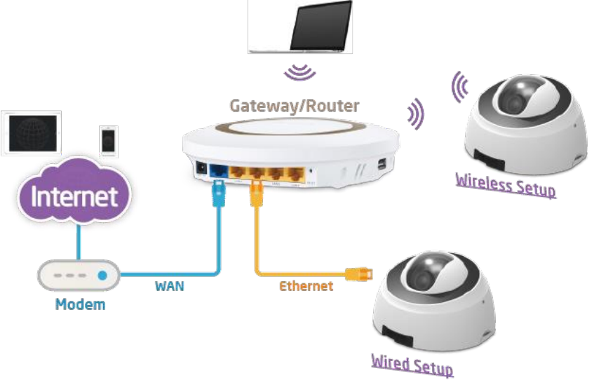
8. Application Guide
This chapter demonstrates some common applications using EnGenius Camera. The examples assume that the camera is already
connected to a router that has Internet accessibility.
Note: Please ensure that your router supports UPnP Traversal and has it enabled. Most of the modern wireless router today supports this
feature. If you can’t find the related settings, they are most likely enabled by default. UPnP Traversal makes camera remote access over the
Internet possible using camera DDNS name (0e95c28.engeniusddns.com).
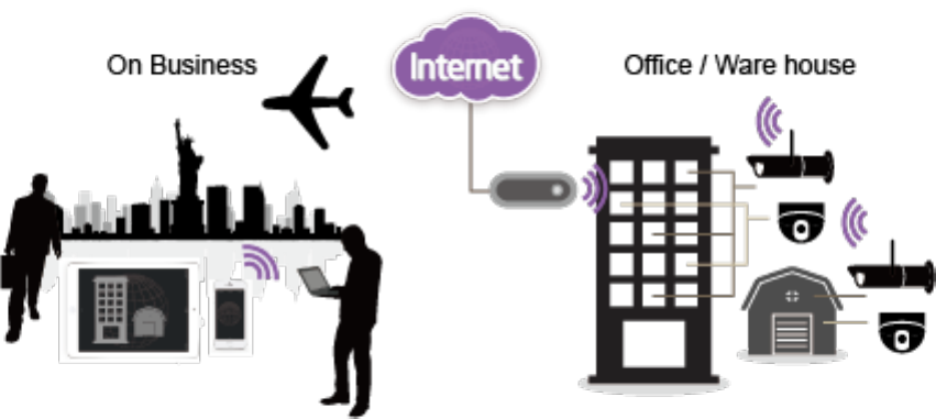
8.1. Example 1: Remote Surveillance and Motion Detection.
The application concept diagram shows a camera monitoring the property like office or warehouse. The management staff wants to remotely
monitor their responsible property and needs to be alarmed when motion (intrusion) is detected.
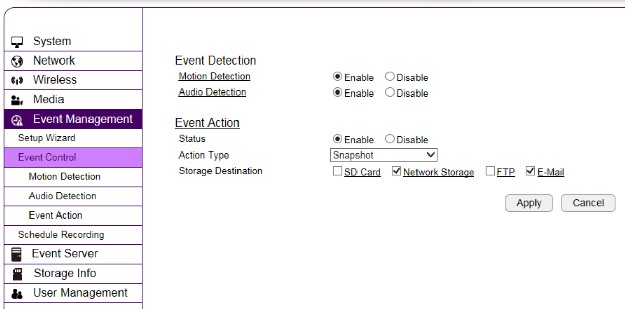
8.1.1. Step 1: Choose Event Control
Please select preferred Event Action; for example here, E-Mail would be suggested.
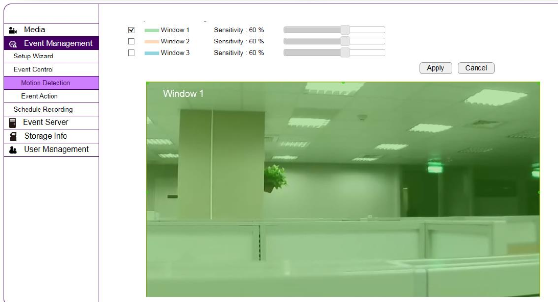
8.1.2. Step 2: Configure Motion Detection
Please specify Window of your interest and click Apply.
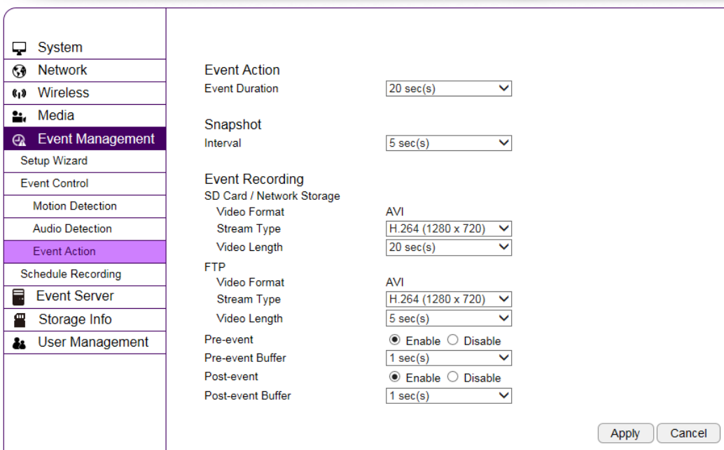
8.1.3. Step 3: Configure Event Action
Select desired Event Duration and Interval; if you enable Event Recording via available methods such as Network Storage or FTP, please also
review related settings regarding length and resolution. Once done, click Apply to activate the settings.

9. Trouble Shooting
9.1. Viewing Your Video
How do I view using a mobile?
You can view your video on your mobile devices (iOS or Android) by using EnViewer. EnViewer is an App that allows you to view and mange
your camera at real time.
Where can I download my app?
You can download it by searching APP store (iOS) or Google Play(Android) for “EnViewer”. You can also scan the following QR code to download
EnViewer directly.
How do I use the web viewer on a computer?
You can view the camera at real time using a web browser. The supported web browsers are Google Chrome and Microsoft Internet
Explorer. Given that you have configured your camera properly, you should be able to get access to your camera by entering its DDNS or IP
address.
If you may have troubles finding your camera on your network, please use the provided utility on the enclosed CD, EnViewer Finder, to
find out your camera’s current IP address.
9.2. Networking
Why does my camera disconnect from my Wi-Fi connection?
There are various reasons that your camera disconnects from the wireless router. Usually it is due to weak Wi-Fi signals or interference
from electrical appliances. Therefore, you should place your camera away from those possible interfering appliances and verify whether it’s
caused by weak signal.
You should also check if router has just rebooted or the administrator has changed Wi-Fi security settings. If your camera is located far
apart from the router, the signal strength may be weak; however, this should not be a problem unless there are many walls or metal obstacles
that may block the wireless signals. Lastly, reboot your camera and router.
How can I minimize interference?
Make sure there is no electrical appliance near the camera, such as microwave or devices that may interfere with the camera. Upon
experiencing interference, try to turn off possible electrical devices that are currently running.
9.3. Security and Privacy
Accessing the camera from the Internet is convenient; however, it is also possible for anyone who has your username and password to
login into your camera. Therefore, it is crucial to keep your username and password safe and change them regularly. Your videos or images are
stored either locally or in network storage. The images and videos are accessible only when provided with proper security check.
Can EnGenius employees view my video?
No! No one can view your video or login into your camera without security check. The username and password is stored locally in your
camera and it is not accessible by anyone but yourself. Therefore, it is important to keep your security information safely.
9.4. Cloud Video Services
If I cannot connect to the cloud service, what should I do next?
Please check your router’s Internet settings. You can first check the Internet connectivity from other devices connecting to the router and
determine possible sources to cause the issue. If other connecting devices can connect to the Internet through the router, the problem may be
caused from other router settings. Check wireless security settings and turn off any firewall rules on the router to see if connection can get
through.
10. Appendix
Federal Communication Commission Interference Statement
This device complies with Part 15 of the FCC Rules. Operation is subject to the following two conditions: (1) This device
may not cause harmful interference, and (2) this device must accept any interference received, including interference that may
cause undesired operation.
This equipment has been tested and found to comply with the limits for a Class B digital device, pursuant to Part 15 of the
FCC Rules. These limits are designed to provide reasonable protection against harmful interference in a residential installation.
This equipment generates, uses and can radiate radio frequency energy and, if not installed and used in accordance with the
instructions, may cause harmful interference to radio communications. However, there is no guarantee that interference will
not occur in a particular installation. If this equipment does cause harmful interference to radio or television reception, which
can be determined by turning the equipment off and on, the user is encouraged to try to correct the interference by one of the
following measures:
- Reorient or relocate the receiving antenna.
- Increase the separation between the equipment and receiver.
- Connect the equipment into an outlet on a circuit different from that
to which the receiver is connected.
- Consult the dealer or an experienced radio/TV technician for help.
FCC Caution: Any changes or modifications not expressly approved by the party responsible for compliance could void the
user's authority to operate this equipment.
This transmitter must not be co-located or operating in conjunction with any other antenna or transmitter.
Radiation Exposure Statement:
This equipment complies with FCC radiation exposure limits set forth for an uncontrolled environment. This equipment
should be installed and operated with minimum distance 20cm between the radiator & your body.