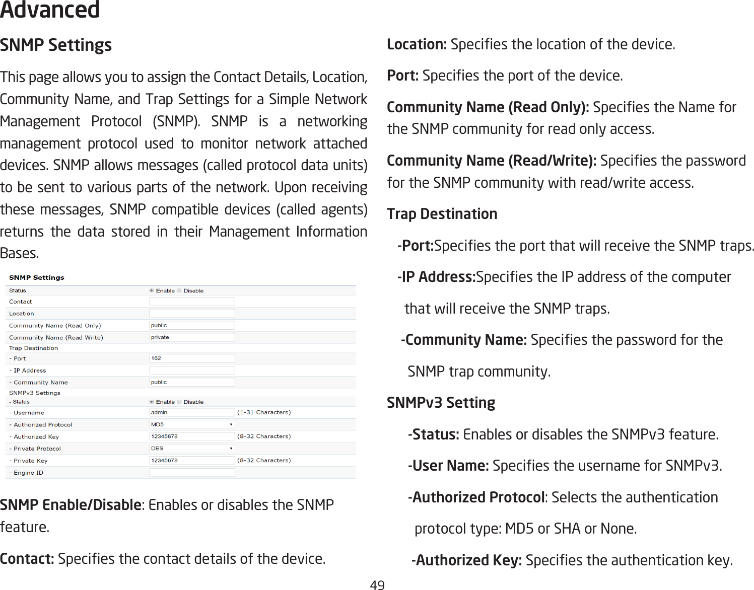
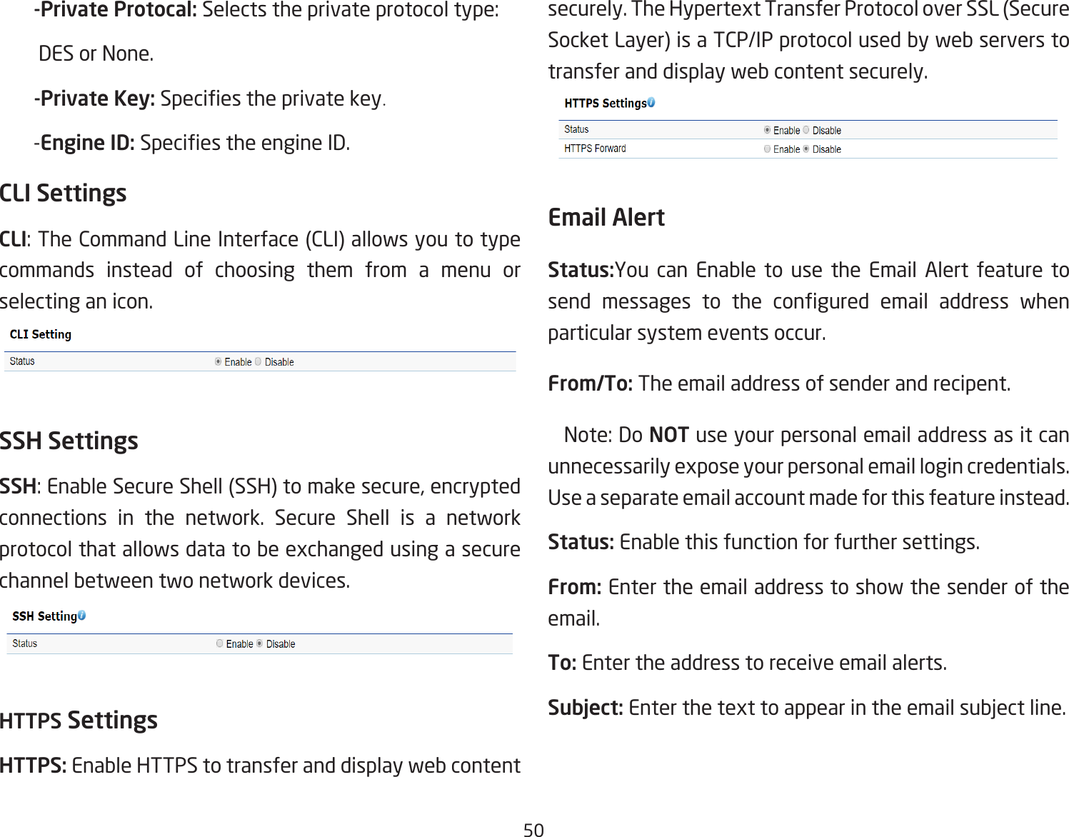
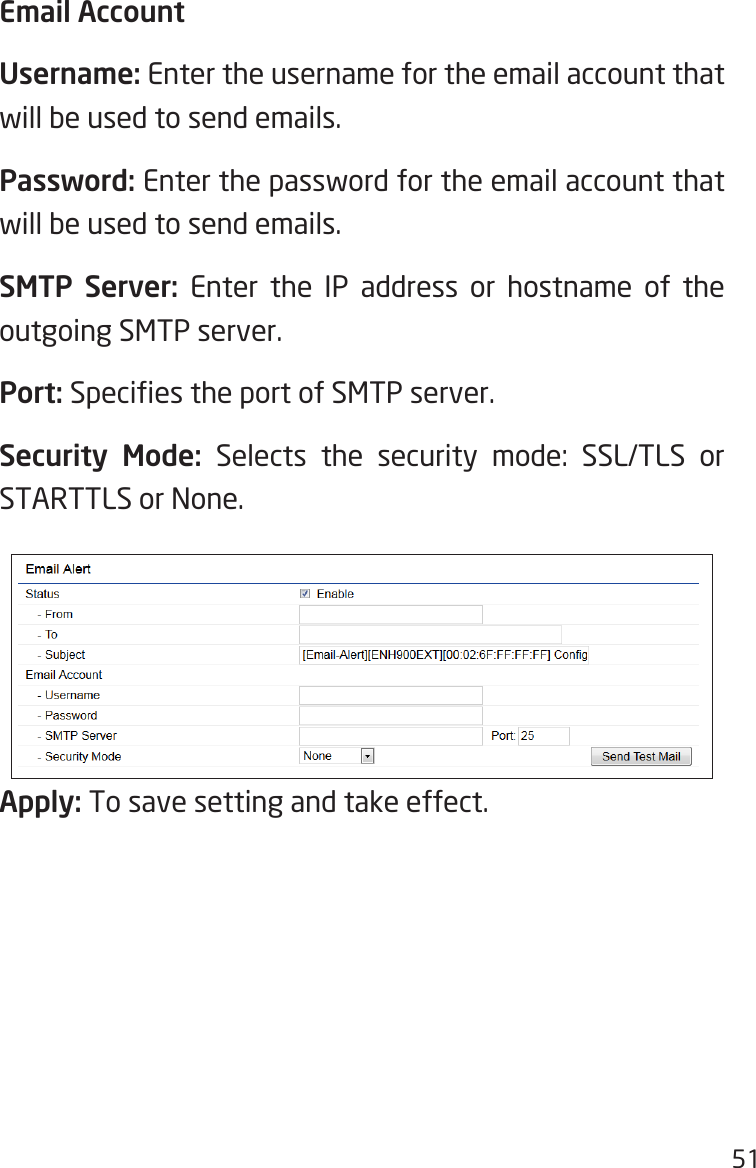
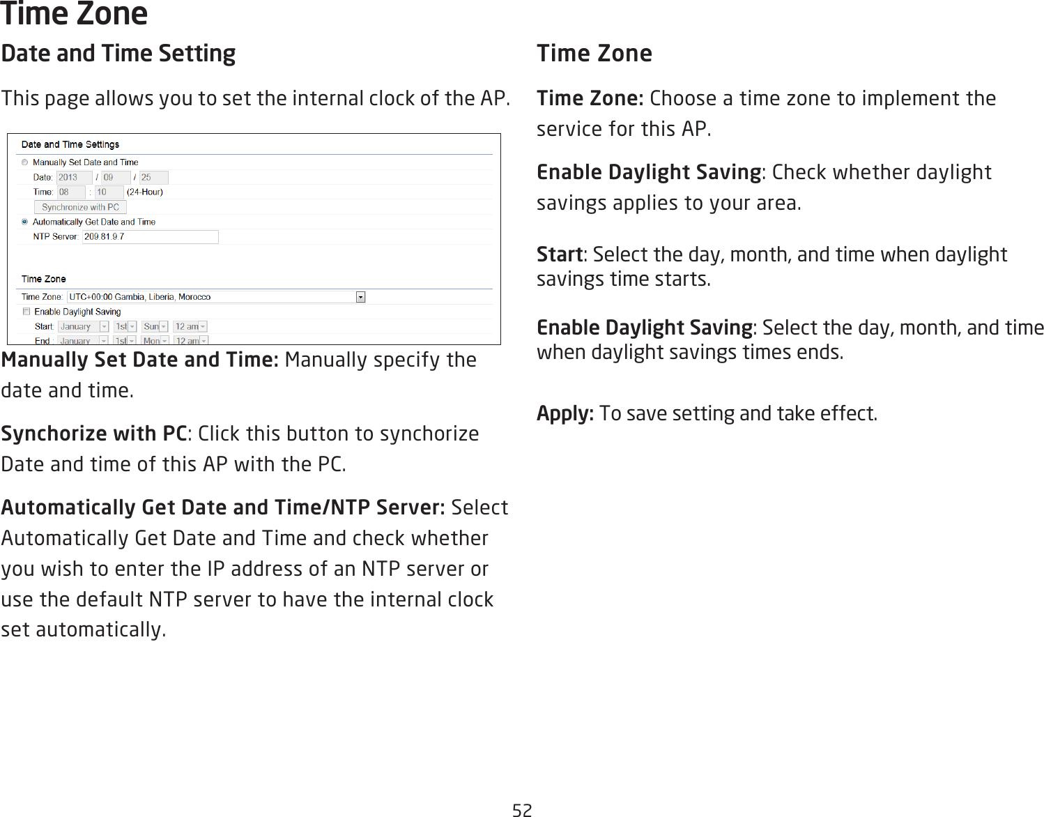
EnGenius Technologies ENS202EXTV2 N300 2.4GHz Outdoor AP User Manual rev

EnGenius Technologies N300 2.4GHz Outdoor AP Users Manual rev

Users Manual_rev.pdf

User ManualBusiness SolutionsN300 2.4GHz Outdoor AP               ENS202v2 / ENS202EXTv2                                                      version 1.0
2IMPORTANTTo install this Access Point please refer to the  Quick Installation Guide included in the product packaging.
3Chapter 1 Product Overview...................................................................... 4         Key Features/Introduction.................................................................5         System Requirements..........................................................................6         Package Contents..................................................................................6         Software Features................................................................................7         Physical Interface...................................................................................8Chapter 2 Before You Begin....................................................................... 9        Computer Settings.............................................................................. 10        Hardware Installation.........................................................................14         Mounting the AP...................................................................................15Chapter 3 Conguring Your Access Point............................................17         Default Settings/Web Conguration............................................18Chapter 4 Building a Wireless Network................................................19        Access Point ......................................................................................... 20        Clien Bridge Mode............................................................................... 21         WDS AP Mode.......................................................................................22         WDS Bridge Mode................................................................................23         WDS Station Mode..............................................................................24Chapter 5 Status............................................................................................25        Overview..................................................................................................26        Connection..............................................................................................29Chapter 6 Network ......................................................................................31        Basic IP Settings...................................................................................32        Spanning Tree Protocol Setting.....................................................33Chapter 7 2.4 GHz Wireless..........................................................................34          Wireless Settings..................................................................................35          2.4 GHz Wireless Network................................................................36          Wireless Security..................................................................................39          Fast Roaming.........................................................................................42          Wireless Trafc Shaping.................................................................. 44          Wireless MAC Filteing.........................................................................43           Guest Network Settings.................................................................. 45          RSSI Threshold......................................................................................46          Manegement VLAN Settings...........................................................47Chapter 8 Management ............................................................................... 48           Advanced Settings............................................................................. 49           CLI/SSH/HTTPS Settings/Email Alr..............................................50           Time Zone..............................................................................................52           Auto Reboot Settings........................................................................53           Wi-Fi Scheduler....................................................................................54           Tools........................................................................................................ 55           Account/Firmware...............................................................................57           Backup/Restore Setting....................................................................58           Log.............................................................................................................60           Logout/Reset.........................................................................................61Appendix..............................................................................................................62           FCC Interference Statement...........................................................63           IC Interference Statement...............................................................64           CE Interference StatEment..............................................................66Table of Contents
4Chapter 1 Product Overview
5Maximum data rates are based on IEEE 802.11 standards. Actual throughput and range may vary depending on many factors including environmental conditions, distance between devices, radio interference in the operating environment, and mix of devices in the network. Features and specications subject to change without notice. Trademarks and registered trademarks are the property of their respective owners. For United States of America: Copyright © 2018EnGenius Technologies, Inc. All rights reserved.Key Features• Supports IEEE802.11b/g/n wireless standards with up to 300 Mbps data rate on 2.4GHz band • Two detachable 5 dBi 2.4 GHz Omni-dipole antennas with ENS202EXT.• Can be used with included power adapter or via PoE with Proprietary 24V.• Fast Transition and Handover between Access Points• Secured Guest Network option availableIntroduction ENS202/ENS202EXT supports Power over Ethernet and Power by Adapter capabilities, which allow the device to be installed easily in nearly any indoor or outdoor location.Also, ENS202EXT provides not only detachable antenna connectors for antenna upgrade, but also high output power and high sensitivity can extend the transmisson range to deliver a stable wireless connection. ENS202EXT integrates 4 operation modes: Access Point, Client Bridge and WDS.Advance  multi-function  operation  modes  offer  exibility in constructing scalable wireless networks for all possible applications. ENS202EXT is designed to deliver reliable service  under  harsh  outdoor  envirnment  with  certied IP65 protection and tailored to accommodate multimedia Introductionstreaming services with data-rate up to 300Mbps. Advanced features include power level control, trafc shapping, and Real time RSSI indication.Most importantly, it  is built-in encryption standards,including Wi-Fi Protected Access (WPA2-PSK) Encryption, and IEEE 802.1x with RADIUS.
6System RequirementsThe following are the Minimum System Requirements in order to congure the device.•  Computer with an Ethernet interface or wireless network capability.•  Windows OS(XP, Vista, 7, 8, 10), Mac OS, or Linux-based operating systems•  Web-Browsing Application (i.e.: Internet Explorer, Firefox, Safari, or another similar browser application).Package ContentsThe ENS202/ENS202EXT package contains the following items:* • ENS202/ENS202EXT Access Point• 2 detachable 5 dBi 2.4 GHz Omni Antenna-ENS202EXT only• PoE Adapter (24V/0.6A)• Wall Mount Kit (Screw set & Adhensive Label)• Pole Mount kit (Cable Tie*2)• Quick Installation Guide*(all items must be in package to issue a refund)
7Multicast SupportedAuto RebootObey Regulatory PowerSecurityWPA2 Personal WPA2 Enterprise Hides SSID in beaconsMAC address ltering, up to 32 MACsWireless STA (Client) connection listHttps SupportSSH SupportQoS (Quality of Service)Complaint with IEEE 802.11e standardStandard:IEEE802.11b/g/n on 2.4 GHzIEEE802.3u(100BASE-TX)/IEEE802.3(10BASE-T)Operation ModesAccess PointClient BridgeWDSWDS DetailWDS APWDS BridgeWDS Station ManagementAuto Channel SelectionMultiple SSID: 8 SSIDs per RadioBSSIDSNMP V1/V2c/V3MIB I/II, Private MIBVLAN Tag/VLAN Pass-throughClients StatisticsSave Conguration as User DefaultFast RoamingE-Mail AlertRADIUS AccountingGuest NetworkControlCLI SupportedDistance Control (Ack Timeout)802.1X Supplicant (CB Mode)Software Features
8Physical InterfaceDimensions and WeightsWith Antenna:100mm(4”)*37.5mm(1.375”)*205mm(8”)(W*D*H)                            Weight: 242gWithout Antenna:100mm(4”)*37.5mm(1.375”)*189mm(7.375”)                                                 (W*D*H)                            Weight: 275g  1  2.4 GHz Antennas: Detachable 5 dBi 2.4 GHz Omni-ENS202EXT only  2  LAN Port (Proprietary 24V PoE Input): Ethernet port for RJ-45 cable.  3  LED Indicators: LED lights for Power, LAN Port, 2.4 GHz Connection   4  Mounting Holes: Using the provided hardware, the ENS202EXT can be attached to a wall or pole.Physical/Environment ConditionsOperating:  Temperature: -4 °F to 158 °F (-20 °C to 70 °C)  Humidity (non-condensing): 0%~90% typicalStorage:   Temperature: -40 °F to 176 °F (-40 °C to 80 °C)  Humidity (non-condensing): 0%~90% typical
9Chapter 2 Before You Begin
10Windows XP/Windows 7/Windows 8/Windows 10In order to use the Access Point, you must rst congure the TCP/IPv4 connection of your Windows OS computer system. 1a. Click the Start button and open the Control Panel1b. Move your mouse to the lower right hot corner to  display the Charms Bar and select the Control Panel in Windows 8 OS.1c. In Windows 10, click Start to select All APPs to enter the folder of Windows system for selecting Control Panel. Computer SettingsWindows XP Windows 7Windows 8Windows 10
112a. In Windows XP, click Network Connections. 2b. In  Windows 7/Windows 8/Windows 10, click View Network Status and Tasks in the Network and Internet section, then select Change adapter settings.3.  Right click on Local Area Connection and select Properties.4.  Select Internet Protocol Version 4 (TCP/IPv4) and then select Properties.5.  Select  Use the following IP address and enter an IP address that is different from the Access Point and Subnet mask, then click OK.
12Note: Ensure that the IP address and Subnet mask are on the same subnet as the device.For example: ENH220EXT IP address: 192.168.1.1  PC IP address: 192.168.1.2 – 192.168.1.255  PC Subnet mask: 255.255.255.0
13Apple Mac OS X1.  Go to System Preferences (Which can be opened in the Applications folder or selecting it in the Apple Menu).2. Select Network in the Internet & Network section.3. Highlight Ethernet.4. In Congure IPv4, select Manually.5. Enter an IP address that is different from the Access Point and Subnet mask then press OK.Note: Ensure that the IP address and Subnet mask are on the same subnet as the device.For example: ENH900EXT IP address: 192.168.1.1  PC IP address: 192.168.1.2 – 192.168.1.255  PC Subnet mask: 255.255.255.06. Click Apply when done.
141.  Connect one end of the Ethernet cable into the LAN port (PoE) of the AP/ Bridge and the other end to the PoE port on the PoE adapter.2.  Connect the Power cord with the PoE Adapter and plug the other end into an electrical outlet.3.  Connect the second Ethernet cable into the LAN port of the PoE adapter and the other end to the Ethernet port on the computer.4.  Screw on the provided antennas to the top of this device.   Note: The AP/Bridge should ONLY be powered via Ethernet cable connected to the included PoE Adapter.This diagram depicts the hardware conguration.Note:  The AP/Bridge should ONLY be powered via Ethernet cable connected to the included PoE Adapter.Hardware InstallationEthernetPCPowerOutletPoE  Adapter
15Mounting the ENS202/ENS202EXTUsing the provided hardware, the ENS202EXT can be attached to a wall or a pole. The height should not exceed 2 meter.1. Wall Mounting Kit (Anchors: Φ5.5*18 mm & Bolts: Φ8*25mm) 2. Pole Mounting Strap(Φ66*12.6 mm)Anchors Bolts
16To attach the ENS202EXT/ENS202EXT to a wall using wall mounting kit.A.  Determine where the Access Point to be placed and stick the Adhesive label on the surface.B.  Use the appropriate drill bit to  drill two 8.1mm diagram and 26mm depth holes on the markings of the label.C.  Remove the label and screw the anchors unto the holes until they are ush with the wall.D. Screw the included screws into the anchors. Place the Access Point against wall with the mounting screw heads.To attach the ENS202EXT to a pole using the provided pole mounting kit:A.  Thread the open end of the Pole Strap through the two tabs on the Pole Mount Bracket.B.Lock and tighten Pole Strap to secure Pole Mount Bracket to the pole.
17Chapter 3 Conguring Your  Access Point
18This  section  will  show  you  how  to  congure  the  device using the web-based conguration interface.Default SettingsPlease use your Ethernet port or wireless network adapter to connect the Access Point.IP Address 192.168.1.1Username / Password admin / admin Web Conguration1.  Open a web browser (Internet Explorer/Firefox/Safari/Chrome) and enter the IP Address http://192.168.1.1Note: If you have changed the default LAN IP Address of the Access Point, ensure you enter the correct IP Address.2. The default username and password are admin. Once you have entered the correct username and password, click the Login button to open the web-base conguration page.*The model name will be varied by different models.3. If successful, you will be logged in and see the User Menu of this Access Point.*The model name will be varied by different modelConguring Your Access Point
19Chapter 4 Building a Wireless  Network
20 Before starting to congure this Access Point, you may realize the used scenario under varied operating modes.The AP has the ability to operate in various modes. This chapter describes purpose of different operating modes and lists down the operating modes for outdoor Access Points.Access Point ModeIn Access Point Mode, AP behaves likes a central connection for stations or clients that support IEEE 802.11ac/a/b/g/n networks. The stations and clients must be congured to use the same SSID (Service Set Identier) and security password to associate with the AP. The AP supports up to eight SSIDs at the same time for secure access.APAccess Point ClientClient ClientClient ClientClient2.4 GHz 5 GHz
21Client Bridge ModeThe AP can be used as a centralized Outdoor Access Point with which other EnGenius Wireless 2.4 or 5 GHz Outdoor Client Bridges can associate; leveraging the long-range capability of their internal high-gain directional antennas, resulting in a very cost-effective solution to expand a company network over a multiple building campus. APAccess PointAPClient BridgeENH202Client BridgeENH202Client BridgeENH500Client BridgeClientClientClientClientClientClientClientClientClientClientClient2.4 GHz5 GHz 5 GHz2.4 GHzSwitchSwitchInternet
22  WDS AP ModeThe AP also supports WDS AP mode. This operating mode allows wireless stations to connect with Access Point via  using WDS technology. In this mode, congure the MAC addresses or SSIDs in both Access Points to enlarge the wireless area by enabling WDS Link settings. WDS supports up to four (4) AP MAC addresses and four (4) SSIDs at the same time.APWDS AP-APWDS AP-2.4 GHz 2.4 GHz5 GHz 5 GHzClient Client Client ClientClientComputerClientComputer
23WDS Bridge ModeIn WDS Bridge Mode, the Accesss Point can wirelessly connect different LANs by conguring the MAC address and security settings of each Access Points. Use this operating mode when two wired LANs located a small distance apart want to communicate with each other. The best solution is to use the Access Point to wirelessly connect two wired LANs, as shown in the following diagram.  WDS Bridge Mode can establish up to four (4) to eight (8) WDS links, creating a star-like network.Note: WDS Bridge Mode does not act as an Access Point. Access Points linked by WDS are using the same frequency channel. More Access Points connected together may lower throughput. APWDS BridgeAPWDS Bridge-APWDS Bridge-ClientComputerClientComputerClientComputer
24WDS Station ModeWDS station (WDS STA) mode expands the WDS by receiving a wireless signal/service and sharing it through the Ethernet port. With WDS STA mode. Access PointWDS APon both 5 GHz or 2.4 GHzAccess PointWDS StationAccess PointWDS StationAccess PointWDS Station
25Chapter 5 Status
26Save ChangesClicking the Change on the right top,this page lets you save and apply the settings shown under Unsaved changes list, or Revert the unsaved changes and revert to the previous settings that were in effect. *The model name will be varied by different models.Device StatusClicking the Device Status link under the Overview menu shows the status information about the current operating mode. •   The Device Information section shows general system information such as Device Name, MAC Address, Current Time, Firmware Version, and Management VLAN ID Note: VLAN ID is only applicable in Access Point, WDS AP or WDS BR mode. *The model name will be varied by different models.Overview
27The Memory Information section shows usage of memory such as Total Available, Free, Cached, Buffered•   The LAN Information section shows the Local Area Network settings such as the LAN IP Address, Subnet mask, Primary DNS Address, Secondary DNS Address, status of DHCP client, and status of Spanning Tree protocol (STP).•   The Wireless LAN Information 2.4 GHz section shows wireless information such as Operating Mode, Frequency, and Channel. Since  this Access Point supports multiple-SSIDs, information about each SSID, the ESSID, and security settings, are displayed Note: Prole Settings are only applicable in Access Point and WDS AP modes.
28•  The Statistics section shows Mac information such as SSID, MAC address, RX and TX.
292.4 GHz Connection ListClick the connection link under the Overview menu displays the connection list of clients associated to the ENS202EXT 2.4 GHz, along with the MAC addresses and signal strength for each client. Clicking Refresh updates the client list.Note:  Only applicable in Access Point and WDS AP modes.2.4 GHz GHz WDS Link ListClick the connection link under the Overview menu. This page displays the current status of the WDS link, including WDS Link ID, MAC Address, Link Status and RSSI.Note: Only applicable in WDS AP and WDS Bridge modes.RealtimeThe Realtime section contains the following options:  CPU Loading: 3 minutes CPU loading percentage information, it displays current loading, average loading and peak loading status. Left bar is loading percentage; button is time tracing. Interval is every 3 secondsConnection   Realtime
30  Trafc Loading: 2.4GHz and Ethernet port inbound and outbound trafc by current, average and peak time.    Realtime Connection (Pkts): Overview on current active network connections. It displays UDP and TCP packets information and other connection status. UDP connections curve is in blue; TCP connection curve is in green; others curve is in red. Below of chart shows connections source and destination.
31Chapter 6 Network
32IPv4/IPv6 SettingsThis page allows you to modify the device’s IP settings.IP Network Settings: Select whether the device IP address will use a static IP address specied in the IP address eld or be obtained automatically when the device connects to a DHCP server.IP Address: The IP address of this device.Subnet Mask: The IP Subnet mask of this device.Gateway: The Default Gateway of this device. Leave it blank if you are unsure of this setting.Primary/Secondary DNS: The primary/secondary DNS address for this device.Save: Click Save to conrm the changes.Basic-IP Settings
33Spanning Tree Protocol (STP) SettingsThis page allows you to modify the Spanning Tree settings. Enabling the Spanning Tree protocol will prevent network loops in your LAN network.Spanning Tree Status: Enables or disables the Spanning Tree function.Default is Disable.Hello Time:  Species  Bridge  Hello  Time  in  seconds.  This value determines how often the device sends handshake packets to communicate information about the topology throughout the entire Bridged Local Area Network.Max Age: Species Bridge Max Age in seconds. If another bridge in the spanning tree does not send a hello packet for a long period of time, it is assumed to be inactive.Forward Delay: Species Bridge Forward Delay in seconds. Forwarding delay time is the time spent in each of the Listening and Learning states before the Forwarding state is entered. This delay is provided so that when a new bridge comes onto a busy network, it analyzes data trafc before participating in the network.Priority: Species the Priority Number. A smaller number has a greater priority than a larger number.Save: Click Save to conrm the changes.
34Chapter 7 2.4 GHz    Wireless
35Wireless Settings*The model name will be varied by different models.Device Name: Enter a name for the device. The name you type appears in SNMP management. This name is not the SSID and is not broadcast to other devices.Wireless
36This page displays the current status of the Wireless settings of the AP.2.4 GHz Wireless NetworkOperation Mode: Scrow down this list to select operation modes for implementing on this radio. The default operation mode is Access Point on base stations and Access Points and is Client Bridge on Client Premise Equipements (CPE).  Meanwhile, EnGenius outdoor devices also support WDS modes for peer to peer or peer to multi-peer connections.Wireless Mode: Scrow down this list to select wireless broadcasting standard on 2.4GHz frequency bands.Channel HT Mode: Scrow down this list to select bandwidth for operating under a frequency band. The default channel bandwidth is 20 MHz on 2.4GHz frequency radio. Considering the different applications, users can decide to implement a channel bandwidth to fulll real applications. The larger the channel, the greater the transmission quality and speed.Channel: Click Configuration button to open a new windows to configure channels for performing wireless service.Transmit Power (Tx Power): Default Tx power is Auto to obey regulartory power of each country.Bit Rate: 2.4GHz is default 1 Mbps, the range can control by BAR via scroll from 1Mbps to 54Mbps.
37Client Limits: Limits the total number of clients on this radio. Once setting the ceiling of client numbers, the maximum assocaited client devices will be restricted at this number.Multicast to Unicast Stream Converison: Stream conversion is default enable and multicastAP Detection: AP Detection can select the best channel to use by scanning nearby areas for Access Points.Distance:  Species  the  distance  between  Access  Points and client devices. The proper setting for this parameter may assist Access Points to avoid the improper operation when transmitting data under a led application. Save: Click Save to conrm the changes or Cancel to cancel and return to previous settings.
382.4 GHz SSID ProleCurrent Prole: You can congure up to four (4)different SSIDs. If multiple client devices will be accessing the network, you can arrange the devices into SSID groups. Click Edit to congure the prole and check whether you  want to enable extra SSID.Wireless Setting-Access Point 2.4GHz *The Wireless Setting will be varied by different models. ENS202/ENS202EXT only support 2.4GHz.Enable: Click this check box to enable this SSID interface. The default SSIDs are enable on the rst 2.4GHz SSID.SSID: Species the SSID for the current prole.Hidden SSID: Check this option to hide the SSID from clients. If checked, the SSID will not appear in the site survey.Client Isolation: Click the appropriate radio button to enable this function for allowing or preventing communication between client devices.VLAN Isolation: Restrict clients communicating with different VIDs by selecting the radio button.ID: Species the VLAN tag for each prole. If your netowrk includes VLANs, you can specify a VLAN ID for packets pass through the Access Point with a tag.L2 Isolation: Enable this function prevenet client devices to communicate on the both WLAN and LAN.Save: Click Save to accept the changes.
39Wireless SecurityThe Wireless Security section lets you congure the AP’s security modesSecuirty Mode: Including WPA2-PSK, WPA2-Enterprise. We strongly recommend you to use WPA2-PSK mode.
40* Setting of WPA2-PSK:Encryption: Default is AES.Please ensure that your wireless clients use the same settings.Passphrase:  Wireless clients must use the same Key to associate the device. If using ASCII format, the Key must be from 8 to 63 characters in length. If using HEX format, the Key must be 64 HEX characters in length.Group Key Update Interval: Species  how  often,  in seconds, the Group Key changes. The default value is 3600* Setting of WPA2-Enterprise (Pre-Shared Key):Encryption: Default is AES.Please ensure that your wireless clients use the same settings.Group Key Update Interval: Species  how  often,  in seconds, the Group Key changes. The default value is 3600Radius Server: Enter the IP address of the Radius server.Radius Port: Enter the port number used for connections to the Radius server.Radius Secret: Enter the secret required to connect to the Radius server.
41Radius SettingsNAS-ID: Enable or disable accounting feature.NAS-Port: Enable or disable accounting feature.NAS-IP: Enable or disable accounting feature.Radius AccountingRadius Accounting: Enable or disable accounting feature.Radius Accounting Server: Enter the IP address of the Radius accounting server.Radius Accounting Port Enter the port number used for connections to the Radius accounting server.Radius Accounting Secret: Enter the secret required to connect to the Radius accounting server.Interim Accounting Interval:  Species  how  often,  in seconds, the accounting data sends.Note: 802.11n does not allow WPA2-PSK TKIP security mode. The connection mode will automatically change from 802.11n to 802.11g.
42Fast RoamingEnable the function to serve mobile client devices that roam from Access Point to Access Point. Some applications running on Client devices require fast re-association when they roam to a different Access PointPlease enter the settings of the SSID and initialize the Security mode to WPA2 enterprise, as well as to set the Radius Server rstly. Users can enable the Fast Roaming and implement the advanced search.Please also set the same enterprise Encryption under the same SSID on other Access Points and enable the Fast  Roaming.  When  the  conguration  is  realized  on different Access Point, the mobile client devices can run the voice service and require seamless roaming to prevent delay in conversation from Access Point to Access Point.           Enable Fast Roaming: Enable or disable fast roaming feature.
43Wireless MAC Filtering is used to allow or deny network access to wireless clients (computers, tablet PCs, NAS, smartphones, etc.) according to their MAC addresses. You can manually add a MAC address to restrict permission to access ENS202EXT. The default setting is: Disable Wireless MAC Filter.Note:  Only applicable in Access Point and WDS AP mode.ACL (Access Control List) Mode: Determines whether network access is granted or denied to clients whose MAC addresses appear in the MAC address table on this page. Choices given are: Disabled, Deny MAC in the list, or Allow MAC in the list.MAC Address: Enter the MAC address of the wireless client you wish to congure for.Add: Click Add to add the MAC address to the MAC Address table.Delete: Deletes the selected entries.Save: Click Save to apply the changes.Wireless MAC Filtering
44Wireless Trafc ShapingTrafc  shaping  regulates  the  ow  of  packets  leaving  an interface to deliver improved Quality of Service.Enable Trafc Shaping: Default is disable. You may check this option to enable Wireless Trafc Shaping per SSID.Download Limit: Species the wireless transmission speed used for downloading. Upload Limit:  Species  the  wireless  transmission  speed used for uploading.Per User:  Check  this  option  to  enable  wireless  trafc shaping per user function. This function allow users to limit the maximum download / upload bandwidth for each client devices on this SSID.Save: Click Save  to  conrm  the  changes  then  back  to prole.
45Guest Network SettingsAdding a guest network allows visitors to use the Internet without  giving  out  your  ofce  or  company  wireless security key. You can add a guest network to each wireless network in the  2.4 GHzb/g/n frequencies.IP address: The IP Address of this device.Subnet Mask: The IP Subnet mask of this device.Starting IP Address: The rst IP Address in the range of the addresses by the DHCP server.Ending IP Address: The last IP Address in the range of addresses assigned by the DHCP server.WINS Server IP:  Windows internet name service server IP Address.
46Enable : Enable the Fast Handover feature by ensuring that each client is served by at least one Access Point at any time. Access Points continuously monitor the connectivity quality  of  any  client  in  their  range  and  efciently  share this information with other Access Points in the vincinity of that client to coordinate which of them should serve the client best.RSSI: Enter the RSSI (Received Signal Strength Index) in order to determine the handover procedure which the current wireless link will terminate. RSSI is an indication of the power level being received by the antenna. Therefore, the higher the RSSI number, the stronger the signal.RSSI Threshold
47Management VLAN SettingsThis page allows you to assign a VLAN tag to packets sent over the network. A VLAN is a group of computers on a network whose software has been congured so that they behave as if they were on a separate Local Area Network (LAN). Computers on VLAN do not have to be physically located next to one another on the LAN.Note:  Only applicable in Access Point and WDS AP modes.Management VLAN: If your network includes VLANs, you can enable Management VLAN ID for packets passing through the Access Point with a tag. Note: If you recongure the Management VLAN ID, you may lose your connection to this AP. Verify that the DHCP  server  supports  the  recongured  VLAN  ID  and then reconnect to this AP using the new IP address. Save: Click Save to conrm the changes.
48Chapter 8 Management
49SNMP SettingsThis page allows you to assign the Contact Details, Location, Community Name, and Trap Settings for a Simple Network Management Protocol (SNMP). SNMP is a networking management protocol used to monitor network attached devices. SNMP allows messages (called protocol data units) to be sent to various parts of the network. Upon receiving these messages, SNMP compatible devices (called agents) returns the data stored in their Management Information Bases.SNMP Enable/Disable: Enables or disables the SNMP feature.Contact: Species the contact details of the device.Location: Species the location of the device.Port: Species the port of the device.Community Name (Read Only): Species the Name for the SNMP community for read only access.Community Name (Read/Write): Species the password for the SNMP community with read/write access.Trap Destination   -Port:Species the port that will receive the SNMP traps.   -IP Address:Species the IP address of the computer      that will receive the SNMP traps.    -Community Name: Species the password for the        SNMP trap community.SNMPv3 Setting      -Status: Enables or disables the SNMPv3 feature.      -User Name: Species the username for SNMPv3.      -Authorized Protocol: Selects the authentication          protocol type: MD5 or SHA or None.       -Authorized Key: Species the authentication key.Advanced
50       -Private Protocal: Selects the private protocol type:          DES or None.       -Private Key: Species the private key.       -Engine ID: Species the engine ID.CLI SettingsCLI: The Command Line Interface (CLI) allows you to type commands instead of choosing them from a menu or selecting an icon.SSH SettingsSSH: Enable Secure Shell (SSH) to make secure, encrypted connections in the network. Secure Shell is a network protocol that allows data to be exchanged using a secure channel between two network devices.HTTPS SettingsHTTPS: Enable HTTPS to transfer and display web content securely. The Hypertext Transfer Protocol over SSL (Secure Socket Layer) is a TCP/IP protocol used by web servers to transfer and display web content securely.  Email AlertStatus:You can Enable to use the Email Alert feature to send  messages  to  the  congured  email  address  when particular system events occur.From/To: The email address of sender and recipent.  Note: Do NOT use your personal email address as it can unnecessarily expose your personal email login credentials. Use a separate email account made for this feature instead.Status: Enable this function for further settings.From: Enter the email address to show the sender of the email.To: Enter the address to receive email alerts.Subject: Enter the text to appear in the email subject line.
51Email AccountUsername: Enter the username for the email account that will be used to send emails.Password: Enter the password for the email account that will be used to send emails.SMTP Server: Enter the IP address or hostname of the outgoing SMTP server.Port: Species the port of SMTP server.Security Mode: Selects the security mode: SSL/TLS or STARTTLS or None.Apply: To save setting and take effect.
52Date and Time SettingThis page allows you to set the internal clock of the AP.Manually Set Date and Time: Manually specify the date and time.Synchorize with PC: Click this button to synchorize Date and time of this AP with the PC.Automatically Get Date and Time/NTP Server: Select Automatically Get Date and Time and check whether you wish to enter the IP address of an NTP server or use the default NTP server to have the internal clock set automatically.Time ZoneTime Zone: Choose a time zone to implement the service for this AP.Enable Daylight Saving: Check whether daylight savings applies to your area.Start: Select the day, month, and time when daylight savings time starts.Enable Daylight Saving: Select the day, month, and time when daylight savings times ends.Apply: To save setting and take effect.Time Zone
53Auto Reboot Settings You can specify how often you wish to reboot the AP.   Status: Enables or disables the Auto Reboot function.Timer: Select the day and enter the time you would like to reboot automatically.Save: Click Save to apply the changes.WiFi Scheduler
54Wi-Fi SchedulerThe Wi-Fi Scheduler can be created for use in enforcing rules. For example, if you wish to restrict web access to Mon-Fri from 3pm to 8pm, you could create a schedule selecting Mon, Tue, Wed, Thu and Fri while entering a Start time of 3pm and End Time of 8pm to limit access to these times.Status: Enables or disables the Wi-Fi scheduler function.SSID Selection: Select a SSID from the drop-down list.Schedule Templates: Select a schedule template from the drop-down list.Availabe: Select available/ unavailable from the drop-down list for the desired days.Duration: The Start Time is entered in two elds. The rst box is for hours and the second box is for minutes. The End Time is entered in the same format as the Start time.Save: Click Save to apply the changes.
55Ping Test Parameters This page allows you to analyze the connection quality of the AP and trace the routing table to a target in the network.Target IP/Domain Name: Enter the IP address or domain name you would like to search.Ping Packet Size: Enter the packet size of each ping.Number of Pings: Enter the number of times you wish to ping.Start: Click Start to begin pinging the target device (via IP).Traceroute TargetTarget IP/Domain Name:Enter the IP address or domain name you wish to trace.Start : Click Start to begin the trace route operation.Nslookup Test ParameterTarget IP/Domain Name:Enter the IP address or domain name you wish to do Nslookup test.Tools
56Speed Test Parameters This page allows you to analyze the connection quality of the AP and trace the routing table to a target in the network.Target IP / Domain Name: Enter an IP address or domain name you wish to impelement a speed test for realizing the variance on wireless speed.Time Period: Enter the time in seconds that you would like the test to implement for and in how many intervals. IPv4/IPv6 Port: This Access Points uses IPv4 5001 and IPv6 60001 port for the speed test.Start: Click start to implement speed test.LED ControlControl LED on/off for Power, LAN interface, or 2.4 GHz WLAN interface.*The LED Control will be varied by different models.Power: Enables or disables the Power LED indicator.Others:  Enables or disables the LAN and WLAN LED indicator.Apply: To save setting and take effect.Device Discovery This page allows you to discover devices from network for Operation Mode, IP Address, System MAC Address and Firmware version.
57Account SettingsThis page allows you to change the AP username and password. By default, the username is admin and the password is admin. The password can contain from 0 to 12 alphanumeric characters and is case sensitive.Administrator Username: Enter a new username for logging in to the New Name entry box.Current Password: Enter the old password for logging in to the Old Password entry box.New Password: Enter the new password for logging in to the New Password entry box.Verify Password: Re-enter the new password in the Conrm Password entry box for conrmation.Apply: Click Apply to apply the changes.Firmware UpgradeThis page allows you to upgrade the firmware of the AP.To Perform the Firmware Upgrade:1.  Click the Choose File button and navigate the OS le system to the location of the upgrade le.2.  Select the upgrade le. The name of the le will appear in the Upgrade File eld.3.  Click the Upload  button  to  commence  the  rmware upgrade.Note:  The device is unavailable during the Firmware upgrade process and must restart when the upgrade is completed. Any connections to or through the device will be lost.Account Firmware
58Backup/Restore SettingThis page allows you to save the current device configurations. When you save your configurations, you also can reload the saved configurations into the device through the Restore Saved Settings from a file section. If extreme problems occur, or if you have set the AP incorrectly, you can use the Reset button in the Revert to Factory Default Settings section to restore all the configurations of the AP to the original default settings.Backup Setting: Click Export to save the current configured settings.Restore New Setting: To restore settings that have been previously backed up, click Browse, select the file, and click Import.Restore to Default: Click Reset button to restore the AP to its factory default settings.
59User SettingThe function allows you to backup the current device configurations into the AP as the default value. If extreme problems occur, or if you have set the AP incorrectly, you can push the Reset button to revert all the configurations of the AP to the user default.Back Up Setting as Default:  Click Backup to backup the user settings you would like to the device’s memory for the default settings.Note1: After setting the current settings as the default, you should click the Restore to Default on the web interface for reverting the settings into the factory default instead of pushing the reset button.Note2: Please write down your account and password before saving. The user settings will now become the new default settings at the next successful login.
60System LogThe AP automatically logs (records) events of possible interest are in its internal memory. To view the logged information, click the Log link under the System Manager menu. If there is not enough internal memory to log all events, older events are deleted from the log. When powered down or rebooted, the log will be cleared.Status: Enable/Disable this function.Trac Log: Enable/Disable this function.Log type: You may choose one of log types to display logs in the following window. The default log types is All. Remote LogThis page allows you to setup the Remote Log functions for the AP.Remote Log: Enable/disable this function.Log Server Port: Enter the port of the log server.Apply: Click Apply to apply the changes.Log
61LogoutLogout: Click Logout in Management menu to logout.*The model name will be varied by different models.Please conrm again to logout the system or not.ResetIn some circumstances, it may be required to force the device to reboot. Click on Reset to reboot the AP*The model name will be varied by different models.Once you click reset button, you will see the options for reboot or restore this AP.Reboot the device: Click it to reboot this device.Restore to Factory Default: Click it to reset this device to factory default setting. Restore to User Default: Click it to reset this device to user default settings. For realizing the setting method, you may refer page 74 and page 75.
62  Appendix
63Federal Communication Commission Interference StatementThis device complies with Part 15 of the FCC Rules. Operation is subject to the following two conditions: (1) This device may not cause harmful interference, and (2) this device must accept any interference received, including interference that may cause undesired operation.This equipment has been tested and found to comply with the limits for a Class B digital device, pursuant to Part 15 of the FCC Rules.  These limits are designed to provide reasonable protection against harmful interference in a residential installation. This equipment generates, uses and can radiate radio frequency energy and, if not installed and used in accordance with the instructions, may cause harmful interference to radio communications.  However, there is no guarantee that interference will not occur in a particular installation.  If this equipment does cause harmful interference to radio or television reception, which can be determined by turning the equipment o and on, the user is encouraged to try to correct the interference by one of the following measures: • Reorientorrelocatethereceivingantenna. • Increasetheseparationbetweentheequipmentandreceiver. • Connecttheequipmentintoanoutletonacircuitdierentfromthattowhichthereceiverisconnected. • Consultthedealeroranexperiencedradio/TVtechnicianforhelp     FCC Caution:     Any changes or modications not expressly approved by the party responsible for compliance could void the user’s authority to operate       this equipment.                      This transmitter must not be co-located or operating in conjunction with any other antenna or transmitter.IMPORTANT NOTE: Radiation Exposure StatementThis equipment complies with FCC radiation exposure limits set forth for an uncontrolled environment. This equipment should be installed and operated with a minimum distance of 20 cm between the radiator & your body. Appendix A
64Industry Canada statementThis device complies with ISED’s licence-exempt RSSs. Operation is subject to the following two conditions: (1) This device may not cause harmful interference, and (2) this device must accept any interference received, including interference that may cause undesired operation. Le présent appareil est conforme aux CNR d’ ISED applicables aux appareils radio exempts de licence. L’exploitation est autorisée aux deux conditions suivantes : (1) le dispositif ne doit pas produire de brouillage préjudiciable, et (2) ce dispositif doit accepter tout brouillage reçu, y compris un brouillage susceptible de provoquer un fonctionnement indésirable. IMPORTANT NOTE: Radiation Exposure StatementThis equipment complies with ISED radiation exposure limits set forth for an uncontrolled environment. This equipment should be installed and operated with greater than 20cm between the radiator & your body.Déclaration d’exposition aux radiationsCet équipement est conforme aux limites d’exposition aux rayonnements ISED établies pour un environnement non contrôlé. Cet équipement doit être installé et utilisé à plus de 20 cm entre le radiateur et votre corps.Appendix B - IC Interference Statement
65DETACHABLE ANTENNA USAGE is radio transmitter IC: 10103A-ENS202EXTv2 / Model: ENS202EXTv2 has been approved by ISED to operate with the antenna type listed below with maximum permissible gain indicated. Antenna types not included in this list, having a gain greater than the maximum gain indicated for that type, are strictly prohibited for use with this device. Le présent émetteur radio IC: 10103A-ENS202EXTV2 / Model: ENS202EXTv2 a été approuvé par ISED pour fonctionner avec les types d’antenne énumérés ci-dessous et ayant un gain admissible maximal. Les types d’antenne non inclus dans cette liste, et dont le gain est supérieur au gain maximal indiqué, sont strictement interdits pour l’exploitation de l’émetteur.  Approved antenna(s) list
66Appendix C - CE Interference StatemenEurope – EU Declaration of ConformityThisdevicecomplieswithDirective2014/53/EUissuedbytheCommissionoftheEuropeanCommunity.- Declaration of ConformityPlease added certication standard in your user manual which depended on the test standards your device performed. or- If the DoC should be a simplied version, please take below as reference –Hereby,EnGeniusNetworksdeclaresthattheEWS550AP/EWS510AP/EWS511APareincompliancewithDirective2014/53/EU.The full text of the EU declaration of conformity is available at the following internet address:Importer:EnGeniusNetworksEuropeB.V.ImporterAddress:ESP240,5633ACEindhoven,TheNetherlandsManufacturer : EnGenius Networks. Inc.ManufacturerAddress:No.500,Fusing3rdRd.,Hwa-YaTechnologyParkKuei-ShanDist.,TaoyuanCity,Taiwan(R.O.C.)CEDoCLink:https://www.engeniusnetworks.eu/ens500ext-ac-ens500-ac-enstation5-accedoc

Navigation menu