EnGenius Technologies ESR750H 802.11abgn Router User Manual ESR750H600H UG
EnGenius Technologies 802.11abgn Router ESR750H600H UG
UserManual.wiki
>
EnGenius Technologies
>
ESR750H User Manual
User Manual
Navigation menu
Upload a User Manual
Namespaces
Wiki Guide
HTML
PDF
Info
Views
User Manual
Discussion / Help
Navigation


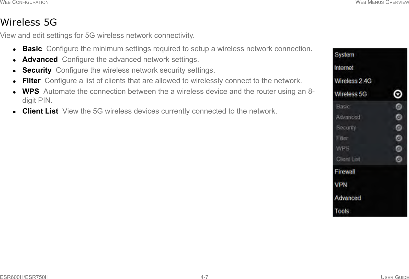


![BASIC NETWORK SETTINGS WIRELESS 2.4G LAN SETUPESR600H/ESR750H 6-26 USER GUIDEAccess Point ModeConfigure the wireless settings of the router in access point mode.Band: Select a wireless standard for the network from the following options:2.4 GHz (B)2.4 GHz (G)2.4 GHz (N)2.4 GHz (B+G)2.4 GHz (B+G+N)Enable SSID# Select the number of wireless groups, between one and four, available on the network.SSID[#] Enter the name of the wireless network(s).Auto Channel Enable or disable having the router auto-matically select a channel for the wireless network. Auto channel is enabled by default. Select disable to manually assign a specific channel. (Default = Disable)Check Channel Time When auto channel is enabled, select time period that the system checks the appropri-ate channel for the router.Channel When auto channel is disabled, select a channel to assign to the wireless network. Valid value are from one to eleven in the US and one to thirteen in the EU.](https://usermanual.wiki/EnGenius-Technologies/ESR750H/User-Guide-1689279-Page-77.png)
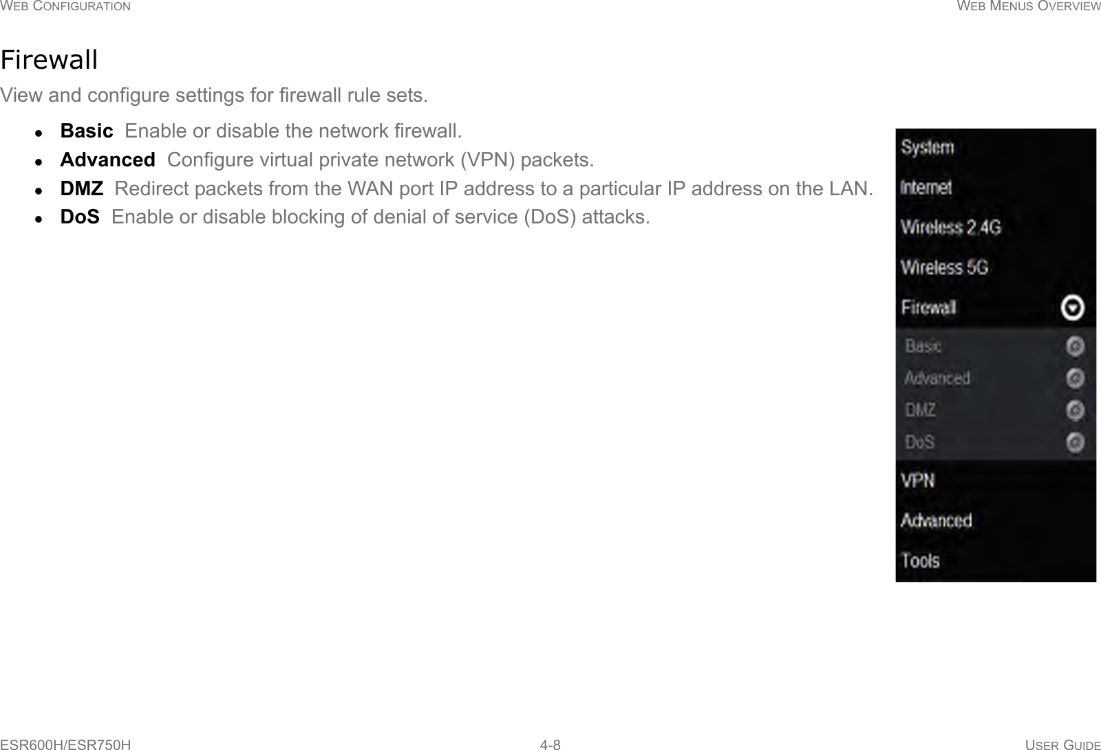
![BASIC NETWORK SETTINGS WIRELESS 2.4G LAN SETUPESR600H/ESR750H 6-27 USER GUIDEWireless Distribution System ModeConfigure the router’s wireless settings in WDS mode.Channel Select a channel to assign to the wireless net-work. Valid value are from one to eleven in the US and one to thirteen in the EU.MAC Address [#] Enter the MAC address(es) for the wireless access point(s) that are part of the WDS.WDS Data Rate Select the data rate for the WDS.Set Security Click Set Security to display the WDS security settings screen. For security configuration set-tings, refer to “WDS Security Settings Screen” on page 6-28.Click Apply to save the settings or Cancel to discard changes.](https://usermanual.wiki/EnGenius-Technologies/ESR750H/User-Guide-1689279-Page-78.png)
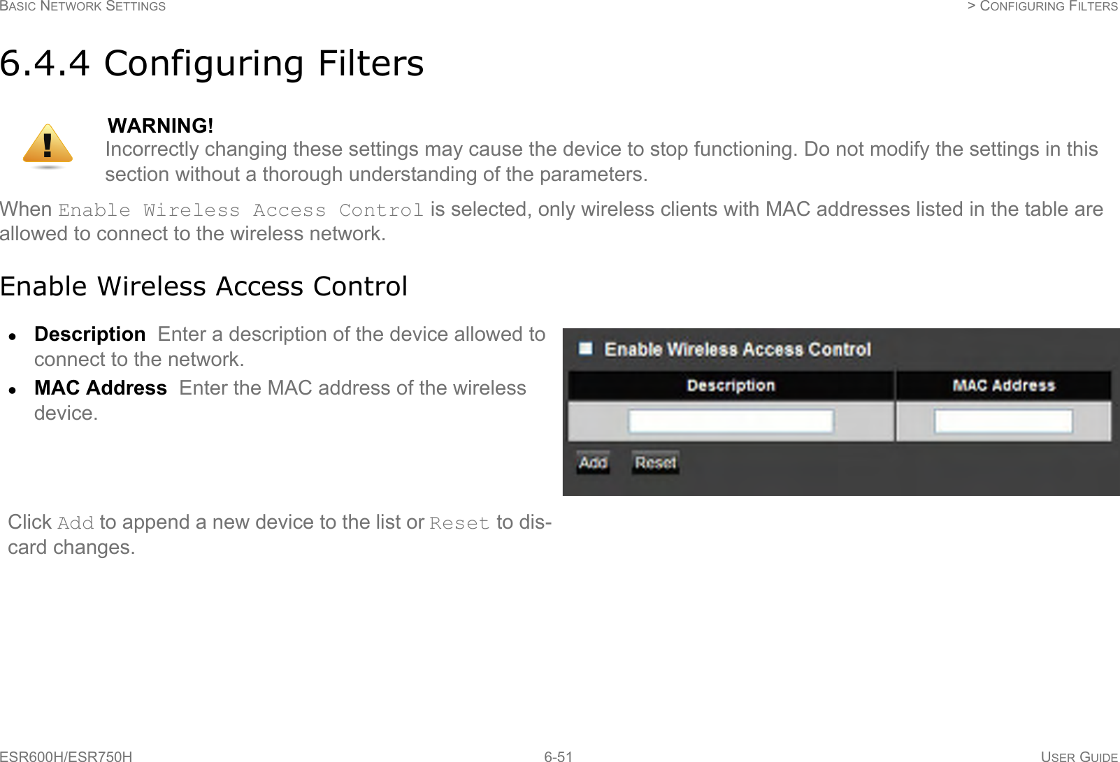
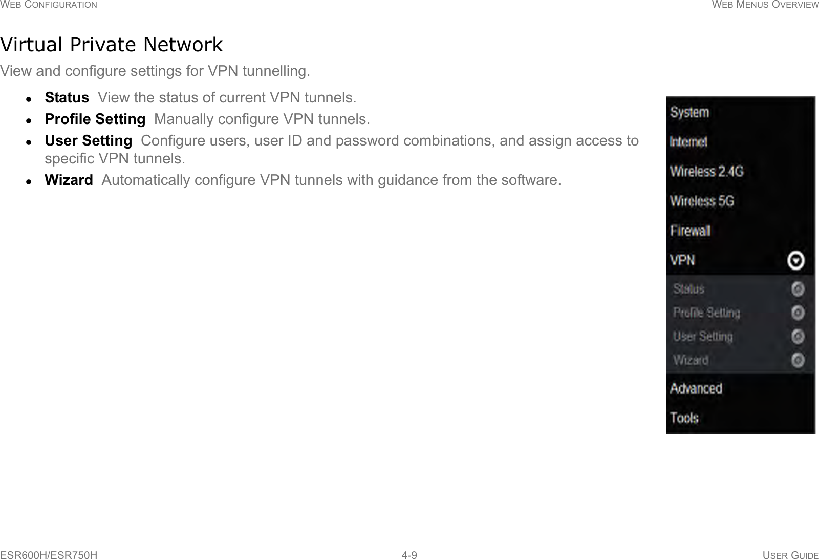
![BASIC NETWORK SETTINGS WIRELESS 2.4G LAN SETUPESR600H/ESR750H 6-28 USER GUIDEWDS Security Settings ScreenSelect the type of WDS encryption (Disable, WEP or WPA Pre-Shared Key) for the wireless network.Wired Equivalent Privacy (WEP)Key Length Select between 64-bit and 128-encryption.Key Format Select the type of characters used for the WEP Key: ASCII (5 characters) or Hexadecimal (10 characters).Default Key Select the default encryption key for wire-less transactions.Encryption Key [#] Enter the encryption key(s) used to encrypt the data packets during data transmission.Click Apply to save the settings or Cancel to discard changes.](https://usermanual.wiki/EnGenius-Technologies/ESR750H/User-Guide-1689279-Page-79.png)


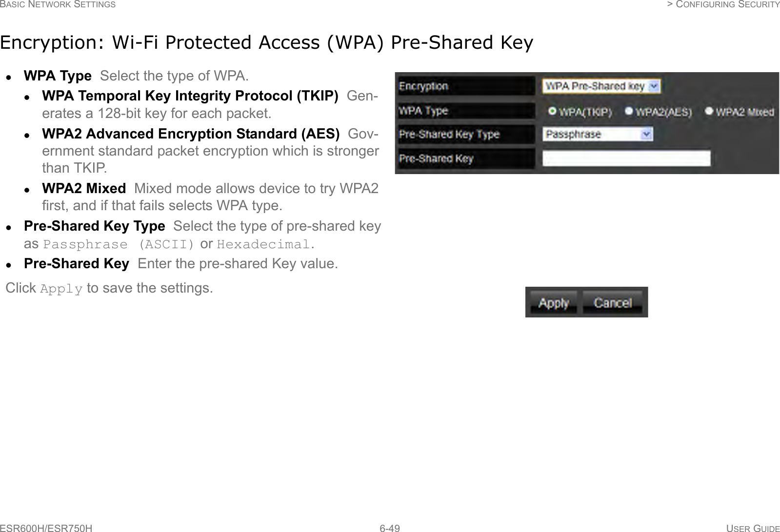
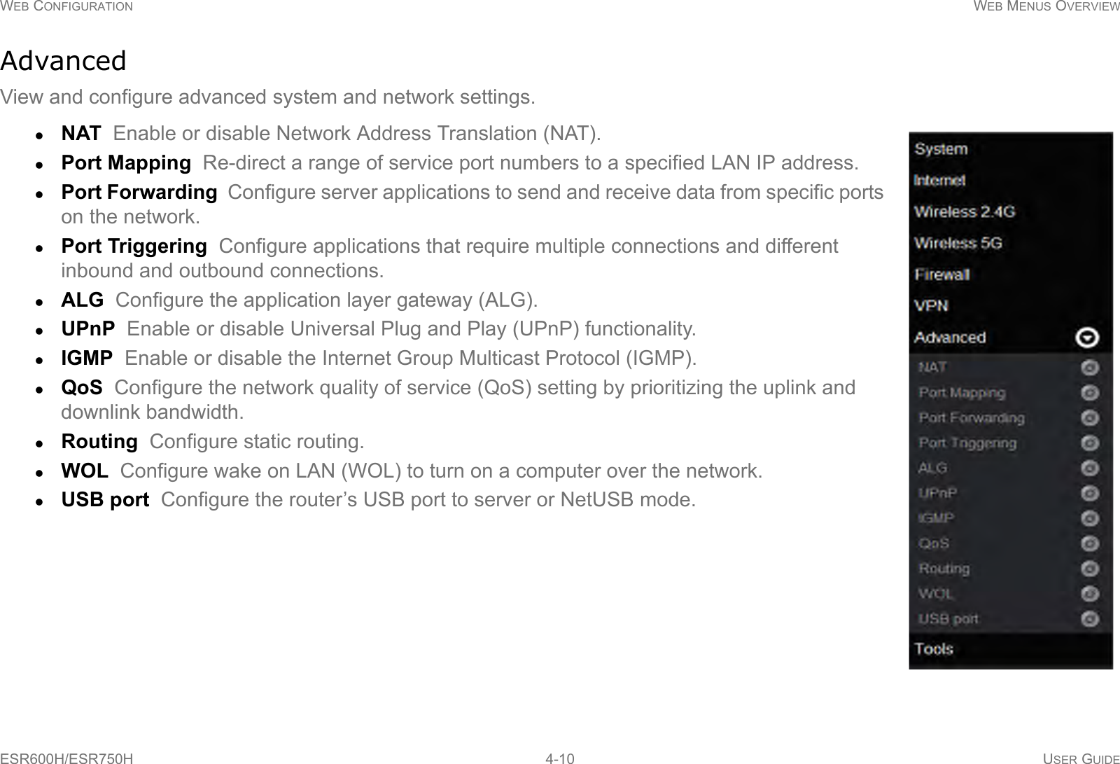
![BASIC NETWORK SETTINGS CONFIGURING SECURITYESR600H/ESR750H 6-33 USER GUIDEEncryption TypeWired Equivalent Privacy (WEP)Authentication Type Select the type of authentication. Open System Wireless stations can associate with the ESR600H/ESR750H without WEP encryptionShared Key Devices must provide the corresponding WEP key(s) when connecting to the ESR600H/ESR750H.Auto Key Length Select between 64-bit and 128-encryption.Key Type Select the type of characters used for the WEP Key: ASCII (5 characters) or Hexadecimal (10 characters).Encryption Key [#] Enter the encryption key(s) used to encrypt the data packets during data transmission.Click Apply to save the settings.](https://usermanual.wiki/EnGenius-Technologies/ESR750H/User-Guide-1689279-Page-84.png)


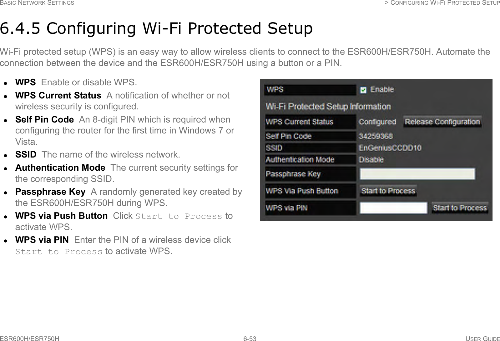
![BASIC NETWORK SETTINGS WIRELESS LAN 5G SETUPESR600H/ESR750H 6-41 USER GUIDEAccess Point ModeConfigure the wireless settings of the router in access point mode.Wireless Distribution System ModeConfigure the wireless settings of the router in WDS mode.Band: Select a wireless standard for the network from the following options:5 GHz (802.11 a)5 GHz (802.11 n)5 GHz (802.11 a/n)Enable SSID# Select the number of wireless groups, between one and four, available on the network.SSID[#] Enter the name of the wireless network(s).Auto Channel Enable or disable having the router auto-matically select a channel for the wireless network. Auto channel is enabled by default. Select disable to manually assign a specific channel. (Default = Disable)Check Channel Time When auto channel is enabled, select time period that the system checks the appropri-ate channel for the router.Channel When auto channel is disabled, select a channel to assign to the wireless network.](https://usermanual.wiki/EnGenius-Technologies/ESR750H/User-Guide-1689279-Page-92.png)
![BASIC NETWORK SETTINGS WIRELESS LAN 5G SETUPESR600H/ESR750H 6-42 USER GUIDEChannel Select a channel to assign to the wireless net-work.MAC Address [#] Enter the MAC address(es) for the wireless access point(s) that are part of the WDS.WDS Data Rate Select the data rate for the WDS.Set Security Click Set Security to display the WDS security settings screen. For security configuration set-tings, refer to “WDS Security Settings Screen” on page 6-43.Click Apply to save the settings or Cancel to discard changes.](https://usermanual.wiki/EnGenius-Technologies/ESR750H/User-Guide-1689279-Page-93.png)
![BASIC NETWORK SETTINGS WIRELESS LAN 5G SETUPESR600H/ESR750H 6-43 USER GUIDEWDS Security Settings ScreenSelect the type of WDS encryption (Disable, WEP or WPA Pre-Shared Key) for the wireless network.Wired Equivalent Privacy (WEP)Key Length Select between 64-bit and 128-encryption.Key Format Select the type of characters used for the WEP Key: ASCII (5 characters) or Hexadecimal (10 characters).Default Key Select the default encryption key for wire-less transactions.Encryption Key [#] Enter the encryption key(s) used to encrypt the data packets during data transmission.Click Apply to save the settings or Cancel to discard changes.](https://usermanual.wiki/EnGenius-Technologies/ESR750H/User-Guide-1689279-Page-94.png)
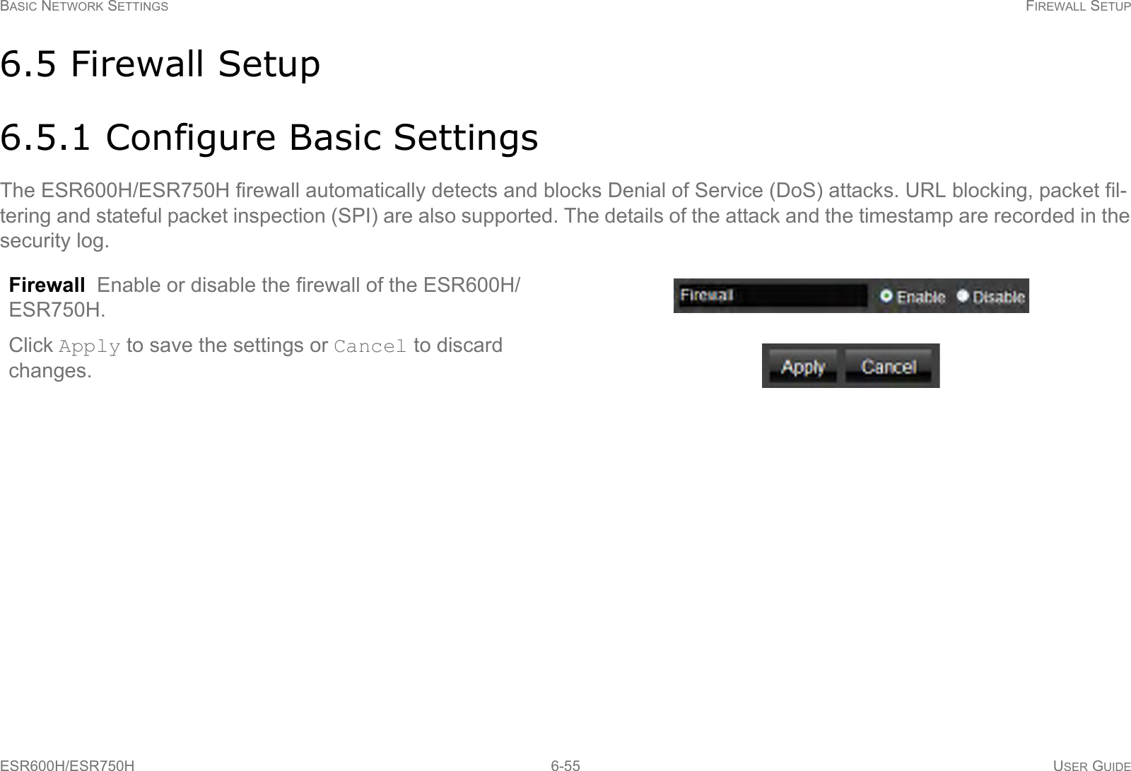
![BASIC NETWORK SETTINGS > CONFIGURING SECURITYESR600H/ESR750H 6-48 USER GUIDEEncryption TypeWired Equivalent Privacy (WEP)Authentication Type Select the type of authentication. Open System Wireless stations can associate with the ESR600H/ESR750H without WEP encryptionShared Key Devices must provide the corresponding WEP key [up to 4] when connecting to the ESR600H/ESR750H.Auto The ESR600H/ESR750H automatically gener-ates a passphrase.Key Length Select between 64-bit and 128-encryption.Key Type Select the type of characters used for the WEP Key: ASCII (5 characters) or Hexadecimal (10 characters).Encryption Key [#] Enter the encryption key(s) used to encrypt the data packets during data transmission.Click Apply to save the settings.Note:Do not use WEP type unless your device can not be upgraded to support WPA. Newer encryption types use stronger encryption than WEP.](https://usermanual.wiki/EnGenius-Technologies/ESR750H/User-Guide-1689279-Page-99.png)