EnGenius Technologies EWS1025CAM 2MP Managed Wireless Mesh AP Camera User Manual EWS Series
EnGenius Technologies 2MP Managed Wireless Mesh AP Camera EWS Series
UserManual.wiki
>
EnGenius Technologies
>
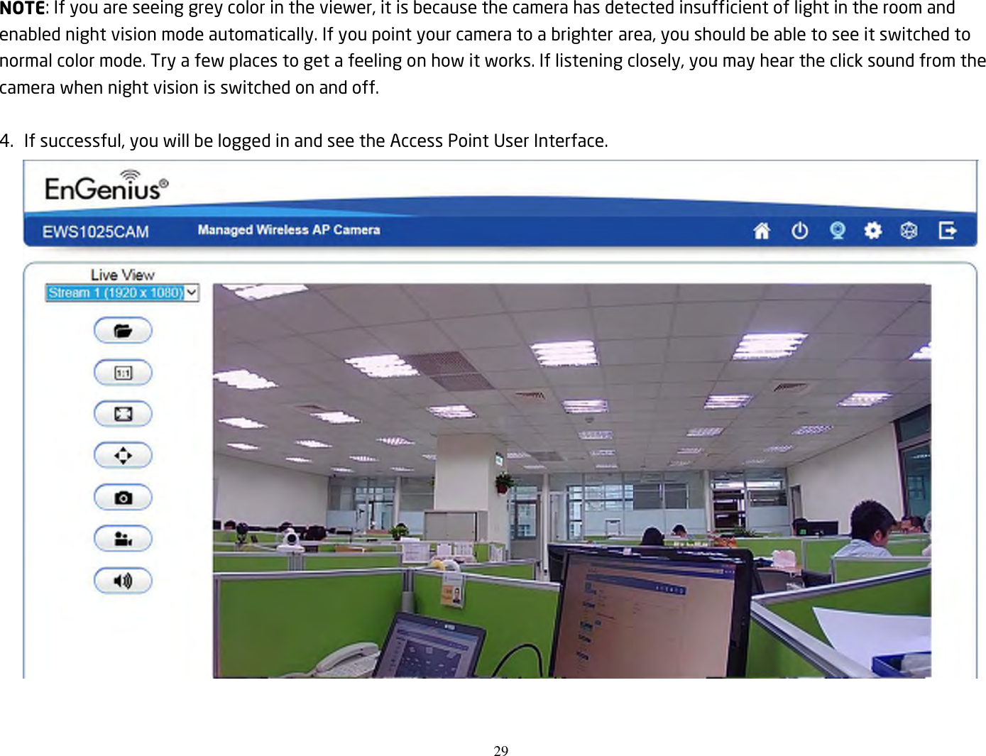
EWS1025CAM User Manual
Users Manual
Navigation menu
Upload a User Manual
Namespaces
Wiki Guide
HTML
PDF
Info
Views
User Manual
Discussion / Help
Navigation