EnOcean EOSW01 WALL-MOUNTED OCCUPANCY SENSOR User Manual USERS MANUAL
EnOcean GmbH WALL-MOUNTED OCCUPANCY SENSOR USERS MANUAL
EnOcean >
USERS MANUAL
Occupancy Sensor - Wall Mounted
Installation Guide
Model: EOSW
Package Contents
Occupancy Sensor
2 screws, 2 wall anchors
1 wide angle lens
(installed)
1 long range lens
Product Description
The wall-mounted Occupancy Sensor saves energy and adds
convenience by accurately detecting when an area is occupied
or vacant.
It is wireless, solar-powered, and uses a passive infrared (PIR)
sensor to detect motion. The occupancy sensor transmits RF sig-
nals that control lighting, HVAC, and outlets to manage building
Features Include:
Sends wireless signals to receiving devices whenever
motion is detected
Harvests indoor light to power the sensor and wireless
communications
corner bracket sold separately
Works with other sensors for enhanced occupancy tracking
Interchangeable lenses for tailored sensor coverage
Supplemental battery or alternative power supply options for
extreme low-light conditions
Power Supply Indoor light energy harvesting
(Optional) Supplemental battery or
2-wire connector for external power
or remote solar cell (3-5VDC)
Transmission Range 80 ft. (25 m)
Radio Frequency EnOcean 315 MHz,
ISO/IEC 14545-3-10 standard
Light Required to
Sustain Operation
50 lux for 30 transmissions/hour
100 lux for 60 transmissions/hour
Charge Time
before Linking
2 minutes @ 50 lux
Charge Time for
Full Charge
3 hours @ 200 lux (after startup)
6 hours @ 200 lux (cold start)
Operating Life in Dark-
ness (after full charge)
48 hours
EEP (EnOcean
A05-07-01
Heartbeat 2 - 12 mins., randomized
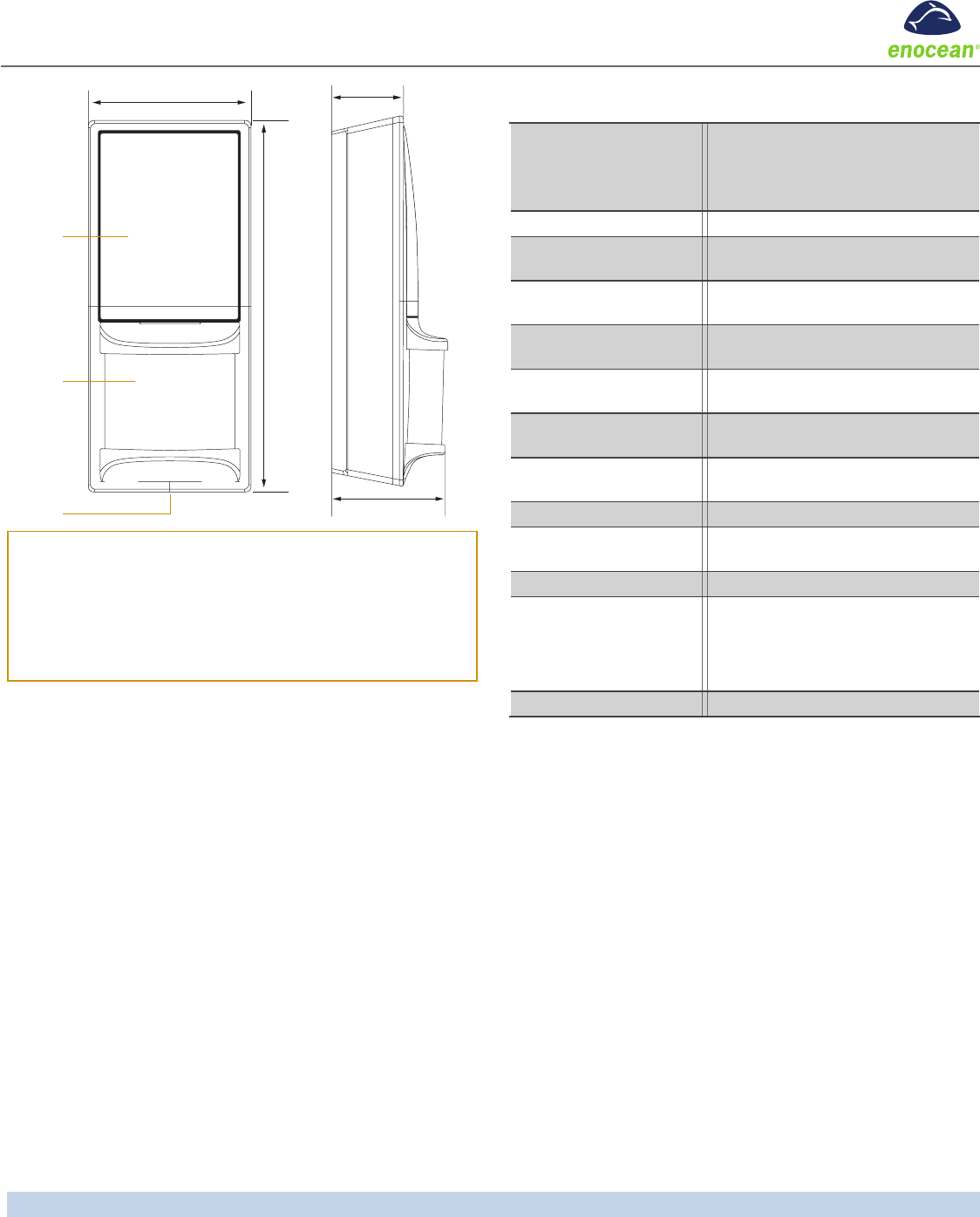
Dimensions 5.83” L x 2.52” W x 1.8” D
(148 mm x 64 mm x 45.7 mm)
Weight 4.09 oz. (116 g)
Environment Indoor use only
14° to 104°F (-10° to 40°C)
20% to 95% relative humidity
(non-condensing)
Agency Compliance FCC, IC
Functional Description
If occupation is detected by the permanently active PIR sensor,
a radio telegram indicating the occupied status will transmit
immediately. An internal timer starts to run with a variable timer
length. The timer value may vary between 60 and 300 seconds,
depending on the light level. No radio telegrams will be sent
out when the timer is counting down.
-
mit again if occupancy was detected during the countdown time
period. If occupancy was not detected, the unit will transmit a
heartbeat signal - sending the unoccupied status with a ran-
dom timing of 2 to 12 minutes. There are two buttons which
allow entrance to a “Walk” or “Light-level” test mode. These
test modes are for installation purposes only and will be exited
automatically after 3 minutes.
Tools Required
Power drill, 3/16” bit
Screwdriver
Leveling tool
Light meter
Battery (CR2032) for testing
Page 1
64mm
148mm
5.8”
2.5”
Solar Cell
Lens
Button
Interface 45.7mm
1.8”
28mm
1.1”
Planning
Take a moment to plan for the sensor’s successful operation and
optimal communication with other system components.
Remove the sensor from its packaging and place it under a
bright light to provide the required startup charge. To quickly
ensure the sensor energy storage is fully charged, insert a
CR2032 battery for 30 seconds.
Ensure the location provides consistent and adequate light
Install with the appropriate lens for the required coverage
Locate the sensor between 8 and 10 ft (2.4 to 3 m) high with
an unobstructed view of the space
moves across the detection pattern, not in and out
example, walking, lounging or sleeping
Provide a minimum clearance of 4 ft. (1.2 m) away from heat
sources, light bulbs, forced air, or ventilation systems
Consider the construction materials (such as metal) in the
space and obstacles that may interfere with RF signals
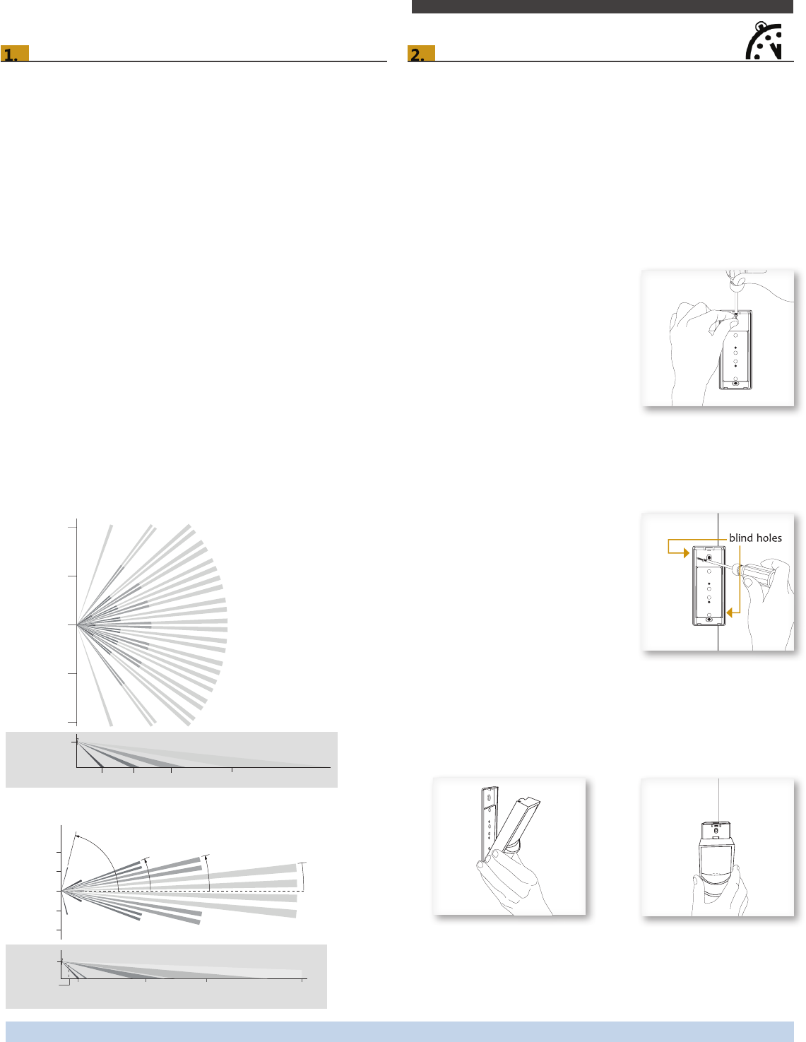
Sensor Range
applications. For some applications, multiple sensors may be
required to provide complete coverage.
Wide Angle Coverage
0
33 ft (10 m)
16 ft (5 m)
16 ft (5 m)
Top View
6.8 ft
(2.1 m)
6 ft 15 ft 25 ft 50 ft
Side View
33 ft (10 m)
Long Range Coverage
16 ft
0
16 ft
8 ft
8 ft
Top View
27°
77°
21.5° 14° 6.5°
center line
Side View
6.8 ft
(2.1 m)
3 ft
(1 m)
7 ft
(2.2 m)
10 ft
(3 m)
35 ft
(10.7 m)
60 ft
(18.3 m)
100 ft
(30.5 m)
Installing
in a corner.
NOTE: It may be easier to link the sensor before it is mounted
on the wall. See the Linking section.
1. Remove the mounting plate from the sensor assembly by
pressing the release tab located on the top of the sensor.
2. Using a level and a pencil, lightly mark two small dots to
align the upper edge of the mounting plate.
3. Decide which of the two installation options is appropriate:
A. Flush to the Wall
i. Orient the mounting plate
using the pencil marks.
Mark the two mounting
screw drill points.
ii. Drill two holes with a 3/16”
drill bit and insert the wall
anchors.
iii.
loosely and level the
mounting plate.
iv. Insert the second screw then hand-tighten
B. Angled in a Corner
i. Orient the mounting plate
using the pencil marks.
ii. Carefully drill through two
of the four blind holes on
the angled sides of the
mounting plate (one on
each side).
iii. Mark the two mounting
screw drill points and drill
two pilot holes with a 3/16”
drill bit and insert the wall anchors.
iv. Insert the two screws and hand-tighten them.
4. Fit the sensor into the groove at the bottom of the mounting
plate and close the top.
estimated time: 20 minutes
Occupancy Sensor – Wall Mounted • Installation Guide
Page 2
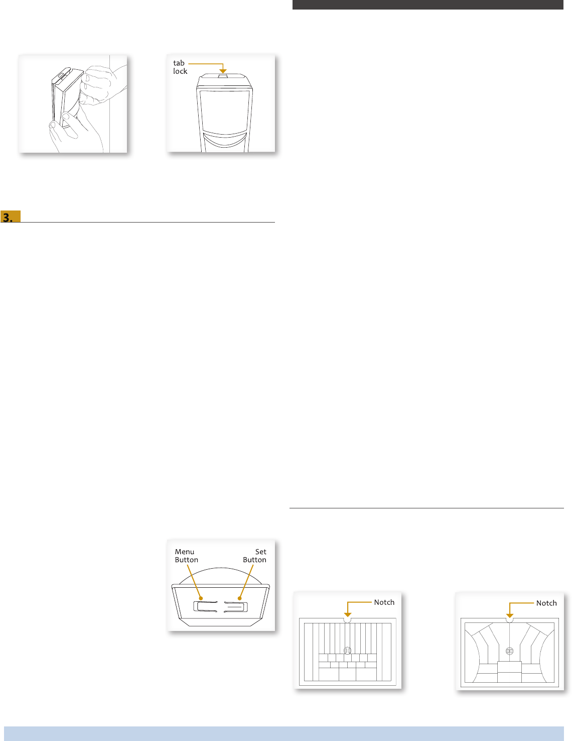
The sensor snaps into the tab at the top.
5.
See Light Test sections.
Linking
to provide the desired control. There are two basic types of
Transmit-only: Transmitters are simple energy-harvesting
devices that send RF messages to communicate a condition,
level, or state. Transmitters can only be linked to transceivers.
Examples > Self-powered Light Switches, Occupancy Sensors
Transmit & Receive: Transceivers are controlling devices
that send as well as receive RF messages. They also process
relevant control logic, and actuate the appropriate outputs
(switching a light on or off for example). Transceivers can be
linked with transmitters as well as other transceivers. A trans-
ceiver can have up to 30 devices linked to it.
Examples > Relays, Gateways
The Occupancy Sensor is a Transmit-only Device.
links.
Next, the desired transmitter, or another transceiver, is triggered
to send a special link message. The awaiting transceiver receives
and stores the link permanently so the devices can interact to
provide a variety of intelligent control options.
To Link or Unlink an Occupancy Sensor
1. Set the desired transceiver to Accept a Link (refer to that
device’s installation guide).
2. Click the Menu button on the
bottom of the sensor once. This
sends a link/unlink radio
telegram.
NOTE: The button interface on the
sensor is used for linking and
testing only. The occupancy timer
transceiver to which the sensor is linked.
Refer to the “Linking” section of the transceiver/controller
installation guides to complete the linking process.
Testing the Sensor
Before starting a test, ensure the sensor’s energy storage is fully
charged by placing it under bright light (at least 200 lux) for 20
minutes, or insert a battery for 5 minutes.
If a battery is used to charge the sensor for a light test, ensure it
is removed to get an accurate light measurement.
A test mode will stay active for 3 minutes. To exit a test and
resume normal operation, press and hold the Menu button for 5
seconds.
Walk Test
range.
1. Press and hold the Set button for 5 seconds.
2. Move in and out of the sensor‘s range to determine its cov-
erage area.
3. -
sor‘s range to see if the motion triggers a response.
Light Test
1. Create a realistic lighting condition (the test measures the
real-time light level).
2. Press and hold the Set button for 10 seconds.
3. Watch the LED blink rate to determine the light strength.
(200 lux or more). 1 blink indicates minimum light (15 lux).
NOTE: If there is no blink rate, consider relocating the sensor
or installing a battery to provide supplemental power. If the
test modes. No LED light or 1 red blink when the test button is
Changing the Lens
The Occupancy Sensor package contains two lenses: a wide
angle lens and a long range lens. The wide angle lens is installed
by default and can be distinguished from the long range lens by
the pattern.
Lens Patterns
Wide Angle Lens Long Range Lens
Occupancy Sensor – Wall Mounted • Installation Guide
Page 3
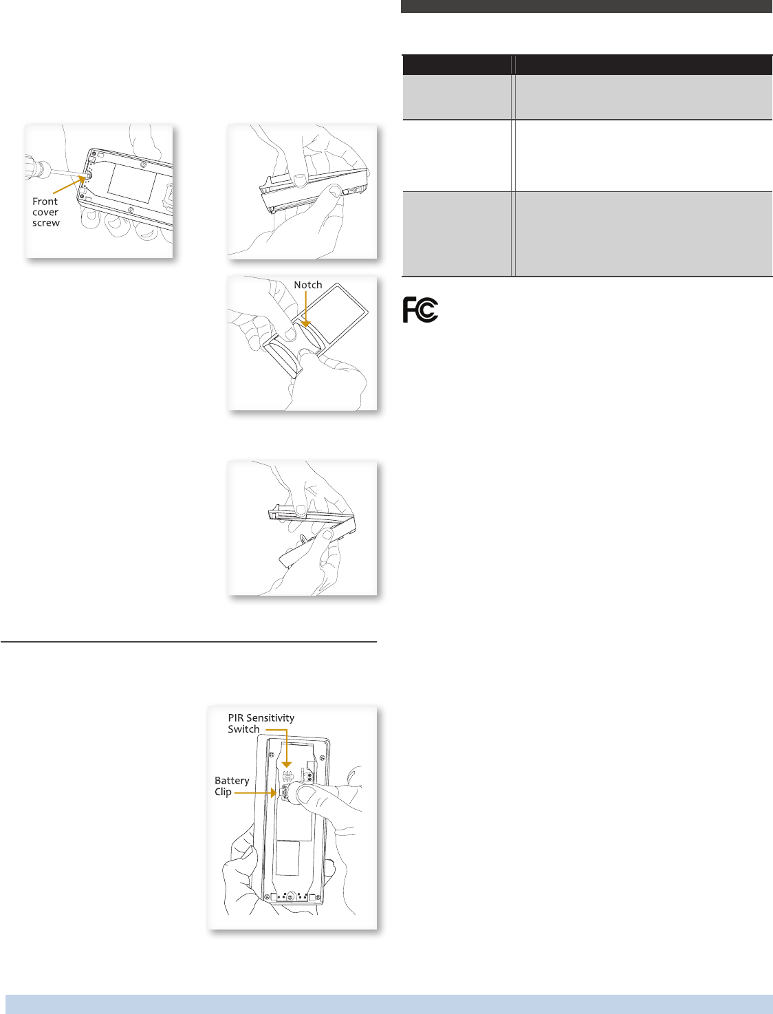
To change the lens:
1. If the sensor is mounted, press the top tab and remove it
from the mounting plate.
2. Unscrew the front cover screw on the back at the bottom
and remove the front cover.
3. Remove the installed lens by
gently squeezing it to ease one
side out of its groove, and then
the other.
4. Insert the lens you want to use
by aligning the notch with the
top on the front cover. Orient the
smooth side facing out, and the
textured side facing the sensor.
5.
NOTE: If the lens is out of
position, the sensor will not
detect activity properly.
6. Replace the top edge of the
front cover and then close it
on the sensor.
7. Replace the bottom screw
and remount sensor on the plate.
Installing Supplemental Battery (optional)
If light levels are very low where the sensor is installed, auxiliary
battery power (CR2032) can be used to supplement the solar
energy harvester.
1. Remove the sensor from the
mounting plate.
2. Unsnap sensor cover and
identify the battery holder
on the circuit board.
3. Insert the battery under the
clip with the positive pole (+)
up and press it in place.
4. Replace cover and remount
the sensor on the wall.
Troubleshooting
Problem Solution Checklist
Sensor does not
generate a wireless
message
Verify the LED blinks when motion is detected
during a walk test
Verify the solar cell is charged properly
Sensor is activated
when there is noth-
ing to detect
Verify there is 4 ft. (1.2 m) clearance from heat
sources that may disturb sensing
Reduce sensitivity setting by moving the PIR
sensitivity switch on the back to low (the left-
hand position)
Linked device does
not respond to
wireless messages
Check for environment or range issues
Verify the device is linked
Check the transceiver connection and the wir-
ing for errors
Check if appropriate devices are linked accord-
ing to good system planning
FCC SZV-EOSW01
IC 5713A-EOSW01
This device complies with part 15 of the FCC rules and Industry Canada ICES-003. Operation
and (2) this device must accept any interference received, including interference that may
cause undesired operation.
for compliance could void the user’s authority to operate this equipment.
Le présent appareil est conforme aux CNR d’Industrie Canada applicables aux appareils radio
exempts de licence. L’exploitation est autorisée aux deux conditions suivantes: (1) l’appareil ne
doit pas produire de brouillage, et (2) l’utilisateur de l’appareil doit accepter tout brouillage
radioélectrique subi, meme si le brouillage est susceptible d’en compromettre le fonc-
tionnement.
partie responsable de la conformité ont pu vider l’autorité de l’utilisateur pour actioner cet
équipment.
Limited Warranty
purchaser that this product will be free from defects in material and workmanship for one year
from the date of your purchase of the product. During that period, if the product does not
comply with this limited warranty, the manufacturer will, at its discretion, repair or replace the
product. Repair or replacement is your sole remedy under this or any other warranty of the
product, whether express or implied.
Coverage Limitations. This limited warranty extends only to the original purchaser and is
not transferable. This limited warranty expressly excludes any defects or damages resulting
from any product installed improperly or in an improper environment, overloaded, misused,
opened, abused, or altered in any manner.
To obtain warranty service - return the product, a description of the problem, together with
your proof of purchase, securely packaged and with postage prepaid, to the manufacturer.
You may be required to provide other information or evidence of the defect. Any returned
product that is replaced becomes the property of thye manufacturer.
Implied Warranties. TO THE EXTENT PERMITTED BY LAW, ANY IMPLIED WARRANTIES, IN-
CLUDING ANY WARRANTY OF MERCHANTABILITY OR FITNESS FOR A PARTICULAR PURPOSE,
ARE LIMITED TO THE SAME DURATION AS THIS EXPRESS WARRANTY. Some states do not
allow limitations on how long an implied warranty lasts, so the above limitation may not apply
to you. NO OTHER EXPRESS WARRANTY HAS BEEN MADE OR WILL BE MADE BY THE MANU-
FACTURER WITH RESPECT TO THIS PRODUCT.
Limitation of Liability. THE MANUFACTURER SHALL NOT BE RESPONSIBLE FOR SPECIAL,
INCIDENTAL OR CONSEQUENTIAL DAMAGES SUCH AS THE COST OF LABOR FOR REMOVAL
OR REINSTALLATION OF THE PRODUCT, WHETHER ARISING OUT OF BREACH OF WARRANTY,
BREACH OF CONTRACT, TORT, OR OTHERWISE. Some states do not allow the exclusion of inci-
dental or consequential damages, so the above exclusion and limitation may not apply to you.
vary from state to state. In Canada, the above provisions are not intended to operate where
prohibited by law and do not preclude the operation of any applicable provisional consumer
protection statute which in certain circumstances may extend the express warranties herein.
Occupancy Sensor – Wall Mounted • Installation Guide
Page 4