EnOcean PTM210U PUSHBUTTON TRANSMITTER DEVICE User Manual
EnOcean GmbH PUSHBUTTON TRANSMITTER DEVICE
UserManual.wiki
>
EnOcean
>
PTM210U User Manual
User Manual
Navigation menu
Upload a User Manual
Namespaces
Wiki Guide
HTML
PDF
Info
Views
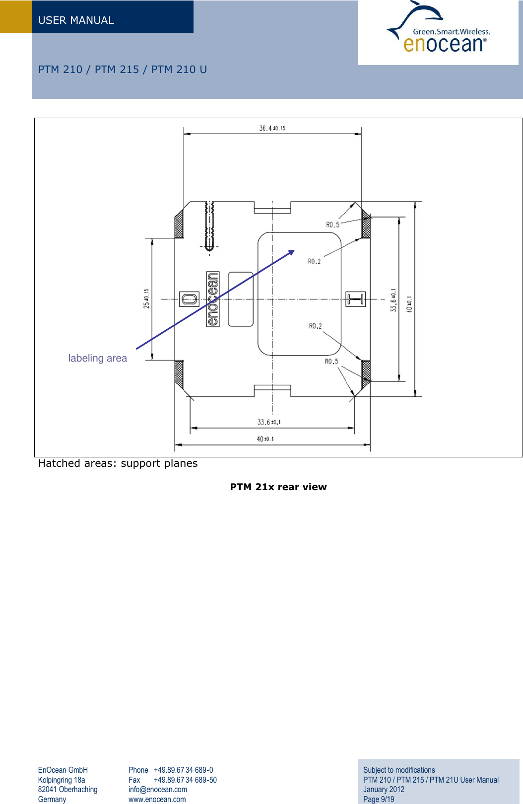
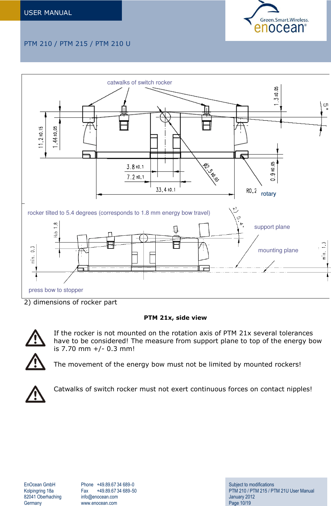
User Manual
Discussion / Help
Navigation