EnOcean PTM215B 2402 MHz - 2480 MHz transmitter User Manual
EnOcean GmbH 2402 MHz - 2480 MHz transmitter
EnOcean >
User Manual

USER MANUAL
PTM 215B – 2.4 GHZ Pusbutton Transmitter Module
© 2016 EnOcean | www.enocean.com F-710-017, V1.0 PTM 215B User Manual | v0.8 | September 2016 | Page 1/42
Patent protected:
WO98/36395, DE 100 25 561, DE 101 50 128,
WO 2004/051591, DE 103 01 678 A1, DE 10309334,
WO 04/109236, WO 05/096482, WO 02/095707,
US 6,747,573, US 7,019,241
Observe precautions! Electrostatic sensitive devices!
PTM 215B BLE Pushbutton Transmitter Module
1
9.09.2016
USER MANUAL
PTM 215B – 2.4 GHZ Pusbutton Transmitter Module
© 2016 EnOcean | www.enocean.com F-710-017, V1.0 PTM 215B User Manual | v0.8 | September 2016 | Page 2/42
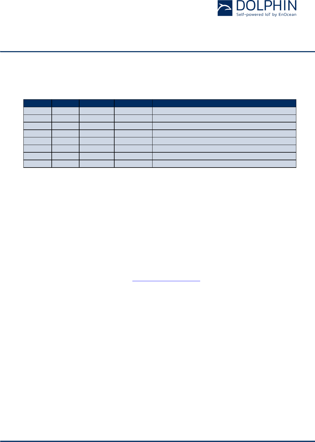
REVISION HISTORY
The following major modifications and improvements have been made to this document:
Version
Author
Reviewer
Date
Major Changes
0.1
MKA
01.05.2016
Initial Release
0.2
MKA
03.05.2016
Added security handling
0.3
MKA
18.05.2016
Added commissioning information
0.4
MKA
30.05.2016
Added NFC information
0.5
MKA
08.06.2016
Added Optional Data field
0.6
MKA
14.06.2016
Added NFC addresses
0.7
MKA
12.09.2016
Added EnOcean company identifier
0.8
MKA
19.09.2016
Added regulatory information
Published by EnOcean GmbH, Kolpingring 18a, 82041 Oberhaching, Germany
www.enocean.com, info@enocean.com, phone +49 (89) 6734 6890
© EnOcean GmbH, All Rights Reserved
Important!
This information describes the type of component and shall not be considered as assured
characteristics. No responsibility is assumed for possible omissions or inaccuracies. Circuitry
and specifications are subject to change without notice. For the latest product specifica-
tions, refer to the EnOcean website: http://www.enocean.com.
As far as patents or other rights of third parties are concerned, liability is only assumed for
modules, not for the described applications, processes and circuits.
EnOcean does not assume responsibility for use of modules described and limits its liability
to the replacement of modules determined to be defective due to workmanship. Devices or
systems containing RF components must meet the essential requirements of the local legal
authorities.
The modules must not be used in any relation with equipment that supports, directly or
indirectly, human health or life or with applications that can result in danger for people,
animals or real value.
Components of the modules are considered and should be disposed of as hazardous waste.
Local government regulations are to be observed.
Packing: Please use the recycling operators known to you.

USER MANUAL
PTM 215B – 2.4 GHZ Pusbutton Transmitter Module
© 2016 EnOcean | www.enocean.com F-710-017, V1.0 PTM 215B User Manual | v0.8 | September 2016 | Page 3/42
TABLE OF CONTENT
1 GENERAL DESCRIPTION ................................................................................. 5
1.1 Basic functionality ......................................................................................... 5
1.2 Technical data ............................................................................................... 6
1.3 Physical dimensions ....................................................................................... 6
1.4 Environmental conditions ............................................................................... 6
1.5 Packaging information .................................................................................... 6
1.6 Ordering information...................................................................................... 6
2 FUNCTIONAL INFORMATION ........................................................................... 7
2.1 PTM 215B Device Overview ............................................................................. 7
2.2 Basic Functionality ......................................................................................... 7
2.3 Block Diagram .............................................................................................. 8
2.4 User Interface ............................................................................................... 9
2.5 PTM 215B radio channel parameters .............................................................. 10
2.5.1 PTM 215B radio transmission sequence .................................................. 10
2.6 PTM 215B button action encoding .................................................................. 11
2.7 PTM 215B commissioning ............................................................................. 12
2.8 Operation modes ......................................................................................... 13
2.8.1 Data mode .......................................................................................... 13
2.8.2 Radio-based commissioning mode ......................................................... 14
2.8.2.1 Commissioning mode entry ................................................................ 14
2.8.2.2 Commissioning telegram transmission ................................................. 15
2.8.2.3 Exit from commissioning mode ........................................................... 15
2.9 BLE frame structure ..................................................................................... 16
2.9.1 Preamble ............................................................................................ 16
2.9.2 Access Address .................................................................................... 16
2.9.3 Header ............................................................................................... 16
2.9.4 Source address .................................................................................... 17
2.9.4.1 Static source address mode ................................................................ 17
2.9.4.2 Private resolvable source address mode ............................................... 18
2.9.5 Check Sum ......................................................................................... 19
2.9.6 Payload .............................................................................................. 20
2.9.6.1 Data Telegram Payload ...................................................................... 20
2.9.6.2 Commissioning Telegram Payload ....................................................... 21
2.10 Telegram authentication ............................................................................... 22
2.10.1 Authentication implementation .............................................................. 23
2.11 NFC interface .............................................................................................. 24
2.11.1 Configuration memory organization........................................................ 24
2.11.2 Memory Address Map ........................................................................... 25
2.11.3 Public data .......................................................................................... 26
2.11.4 Protected Data .................................................................................... 26
2.11.4.1 PIN Code ......................................................................................... 27
2.11.4.1 Modifying product parameters ............................................................ 27
2.11.4.2 Source Address Write register............................................................. 27
2.11.4.3 Security Key Write register ................................................................. 28

USER MANUAL
PTM 215B – 2.4 GHZ Pusbutton Transmitter Module
© 2016 EnOcean | www.enocean.com F-710-017, V1.0 PTM 215B User Manual | v0.8 | September 2016 | Page 4/42
2.11.4.4 Product ID Write register ................................................................... 29
2.11.4.1 Optional Data register ....................................................................... 29
2.11.4.2 Configuration register ........................................................................ 30
2.11.4.3 Customer Data ................................................................................. 30
2.11.5 Private Data ........................................................................................ 31
2.11.5.1 Security Key ..................................................................................... 31
2.11.5.2 Default Settings ................................................................................ 31
2.12 Factory Reset .............................................................................................. 32
3 Device Integration ....................................................................................... 33
3.1 Mechanical Interface Characteristics .............................................................. 33
3.2 Mechanical Interface Drawings ...................................................................... 33
3.3 Device Label ............................................................................................... 38
3.3.1 Device DMC ........................................................................................ 39
4 APPLICATION INFORMATION ........................................................................ 40
4.1 Transmission range ..................................................................................... 40
5 REGULATORY INFORMATION......................................................................... 41
5.1 FCC (United States) Certificate ...................................................................... 41
5.1.1 FCC (United States) Regulatory Statement.............................................. 41
5.2 IC (Industry Canada) Certificate .................................................................... 42
5.2.1 IC (Industry Canada) Regulatory Statement ............................................ 42
USER MANUAL
PTM 215B – 2.4 GHZ Pusbutton Transmitter Module
© 2016 EnOcean | www.enocean.com F-710-017, V1.0 PTM 215B User Manual | v0.8 | September 2016 | Page 5/42
1 GENERAL DESCRIPTION
1.1 Basic functionality
PTM 215B enables the realization of energy harvesting wireless switches for EnOcean sys-
tems communicating based on the 2.4 GHz BLE communication standard.
PTM 215B is mechanically compatible with the established PTM 21x form factor enabling
quick integration into a wide range of designs. Key applications are wall-mounted or porta-
ble switches either with up to two rockers or up to four push buttons.
PTM 215B pushbutton transmitters are self-powered (no batteries) and fully maintenance-
free. They can therefore be used in all environments including locations that are difficult to
reach or within hermetically sealed housings. The required energy is generated by an elec-
tro-dynamic energy transducer actuated by an energy bow located on the left and right of
the module. This energy bow which can be pushed from outside the module by an appro-
priate pushbutton or switch rocker.
When the energy bow is pushed down or released, electrical energy is created and a radio
telegram according to the 2.4 GHz BLE standard is transmitted. This radio telegram trans-
mits the operating status of all four contact nipples at the moment when the energy bow
was pushed down or released.
PTM 215B radio telegrams are protected with AES-128 security based on a device-unique
private key.
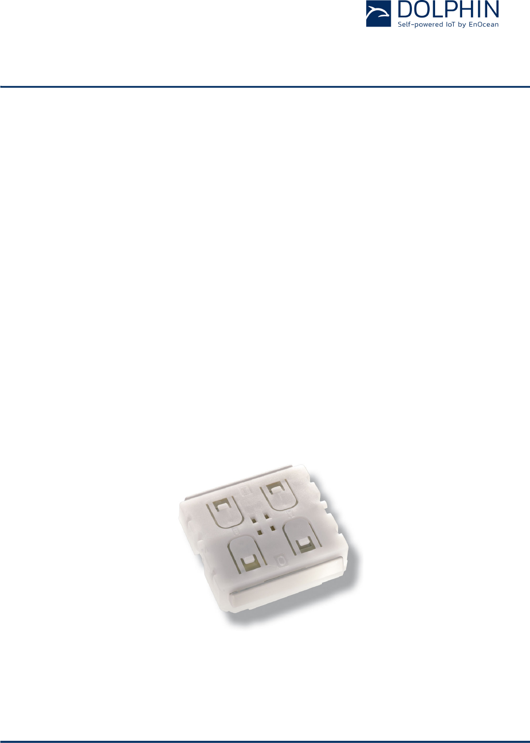
Figure 1 below shows PTM 215B.
Figure 1 – PTM 215B Product Outline

USER MANUAL
PTM 215B – 2.4 GHZ Pusbutton Transmitter Module
© 2016 EnOcean | www.enocean.com F-710-017, V1.0 PTM 215B User Manual | v0.8 | September 2016 | Page 6/42
1.2 Technical data
Antenna
Integrated antenna
Output Power
0 dBm
Communication Range (Guidance Only)
75 m ideal line of sight / 10 m indoor environment
Communication Standard
BLE Advertising
Radio Frequency (min / max)
2402 MHz / 2480 MHz
Default Radio Channels
BLE CH 37 / 38 / 39 (2402 MHz / 2426 MHz / 2480 MHz)
Advertising Events per action (min / max)
2 / 3
Data Rate and Modulation
1 Mbit/s GFSK
Configuration Interface
NFC Forum Type 2 Tag (ISO/IEC 14443 Part 2 and 3)
Device Identification
Individual 48 Bit Device ID (factory programmed)
Security
AES128 (CBC Mode) with Sequence Code
Power Supply
Integrated Kinetic Energy Harvester
Button Inputs
Up to four buttons or two rockers
1.3 Physical dimensions
Module Dimensions
40.0 x 40.0 x 11.2 mm
Module Weight
20 g
1.4 Environmental conditions
Operating Temperature
-25°C ... 65°C
Storage Temperature
-25°C ... 65°C
Humidity
0% to 95% r.h. (non-condensing)
1.5 Packaging information
Packaging Unit 100 units
Packaging Method Tray / Box (10 units per tray, 10 trays per box)
1.6 Ordering information
Type
Ordering Code
Frequency
PTM 215B S3221-A215
2.4 GHz (BLE)
USER MANUAL
PTM 215B – 2.4 GHZ Pusbutton Transmitter Module
© 2016 EnOcean | www.enocean.com F-710-017, V1.0 PTM 215B User Manual | v0.8 | September 2016 | Page 7/42
2 FUNCTIONAL INFORMATION
2.1 PTM 215B Device Overview
The pushbutton transmitter module PTM 215B from EnOcean enables the implementation of
wireless remote controls without batteries. Power is provided by a built-in electro-dynamic
power generator. PTM 215B device transmits data based on the 2.4GHz BLE standard.
The outer appearance of PTM 215B is shown on the picture below.
Figure 2 – Electro-dynamic powered pushbutton transmitter module PTM 215B
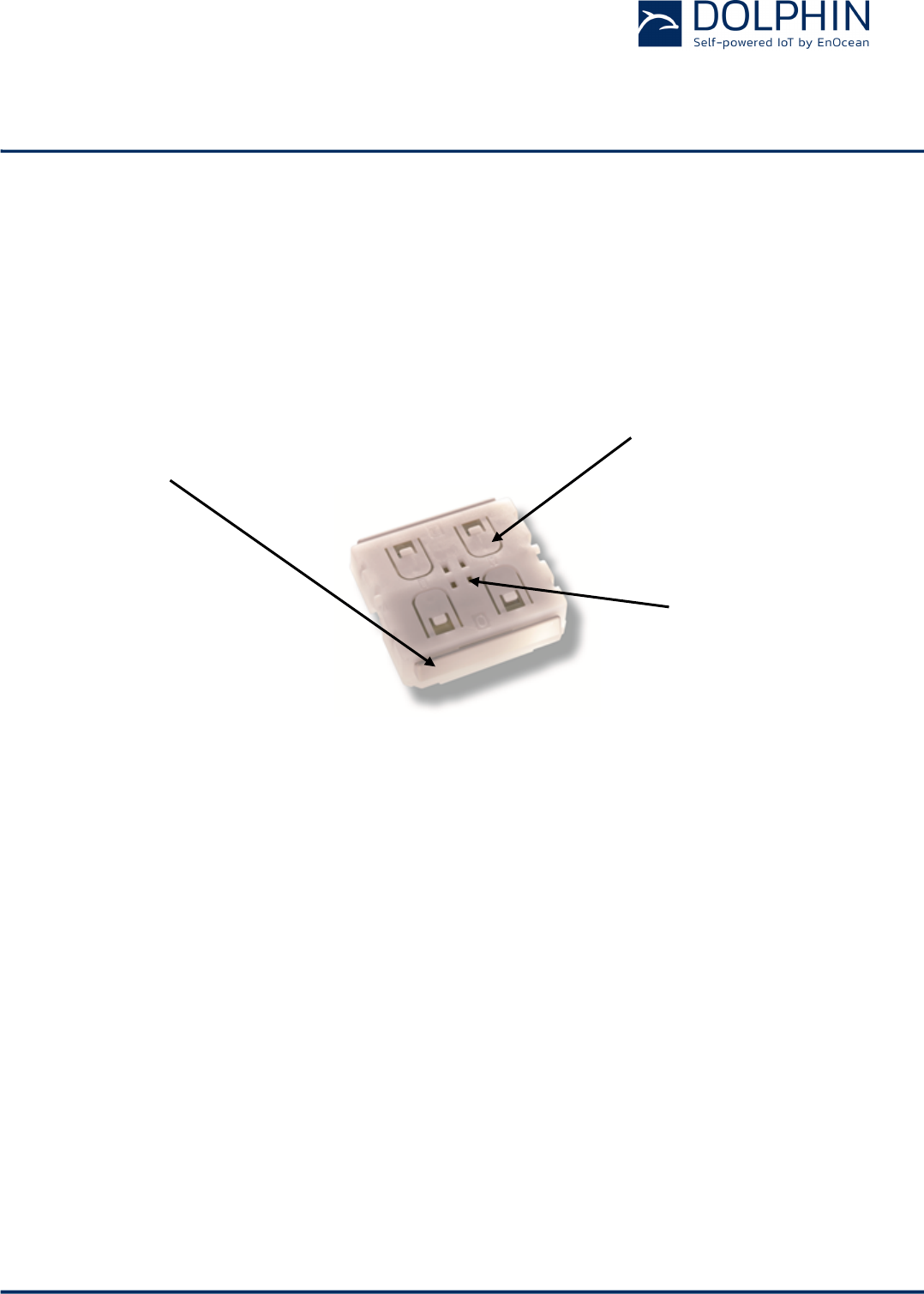
2.2 Basic Functionality
PTM 215B devices contain an electro-dynamic energy transducer which is actuated by an
energy bow (1). This bow is pushed by an appropriate push button, switch rocker or a simi-
lar construction mounted onto the device. An internal spring will release the energy bow as
soon as it is not pushed down anymore.
When the energy bow is pushed down, electrical energy is created and an BLE radio tele-
gram is transmitted which identifies the status (pressed or not pressed) of the four button
contacts (2). Releasing the energy bow similarly generates energy which is used to trans-
mit a different radio telegram.
It is therefore possible to distinguish between radio telegrams sent when the energy bar
was pushed and radio telegrams sent when the energy bar was released.
By identifying these different telegrams types and measuring the time between pushing
and releasing of the energy bar, it is possible to distinguish between “Long” and “Short”
button contact presses. This enables simple implementation of applications such as dim-
ming control or blinds control including slat action.
(2) Button contacts
for switch rocker
identification
(1) Energy bow
on both device sides
Rotation axis for
pushbuttons or
switch rocker
USER MANUAL
PTM 215B – 2.4 GHZ Pusbutton Transmitter Module
© 2016 EnOcean | www.enocean.com F-710-017, V1.0 PTM 215B User Manual | v0.8 | September 2016 | Page 8/42
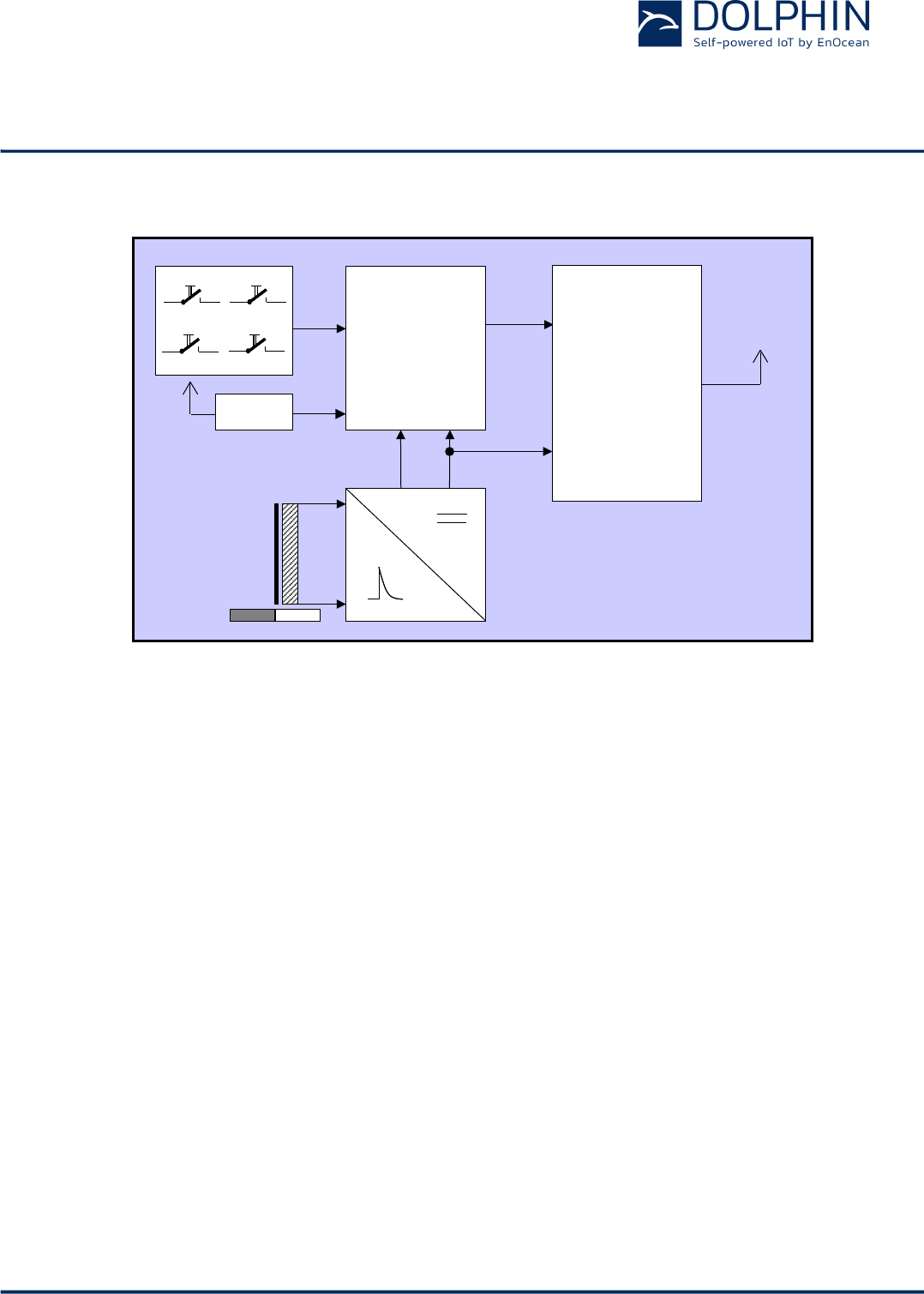
2.3 Block Diagram
Figure 3 – Functional block diagram of PTM 215B
Energy Bow / Power Generator
Converts the motion of the energy bow into electrical energy
Power Converter
Converts the energy of the power generator into a stable DC supply voltage for the device
electronics
Processor
Determines the status of the button contacts and the energy bow, encodes this status into
a data word, generates the proper radio telegram structure and sends it to the radio
transmitter
RF transmitter
Transmits the data in the form of a series of short BLE 2.4 GHz radio telegrams using the
integrated antenna
NFC interface
Allows reading and writing certain product parameters using an NFC compliant reader /
writer supporting NFC Forum Type 2 tags (as specified by ISO/IEC 14443 Part 2 and 3).
Processor
Energy
Bow
Powe
Converte
Dat
DC
Pushed
/
Released
Ant
N
S
Processor
Button Contacts
Energy
Bow
Power
Converter
Dat
DC
Push / Release
Detection
Antenna
N
S
N
S
NFC
RF Transmitter
USER MANUAL
PTM 215B – 2.4 GHZ Pusbutton Transmitter Module
© 2016 EnOcean | www.enocean.com F-710-017, V1.0 PTM 215B User Manual | v0.8 | September 2016 | Page 9/42
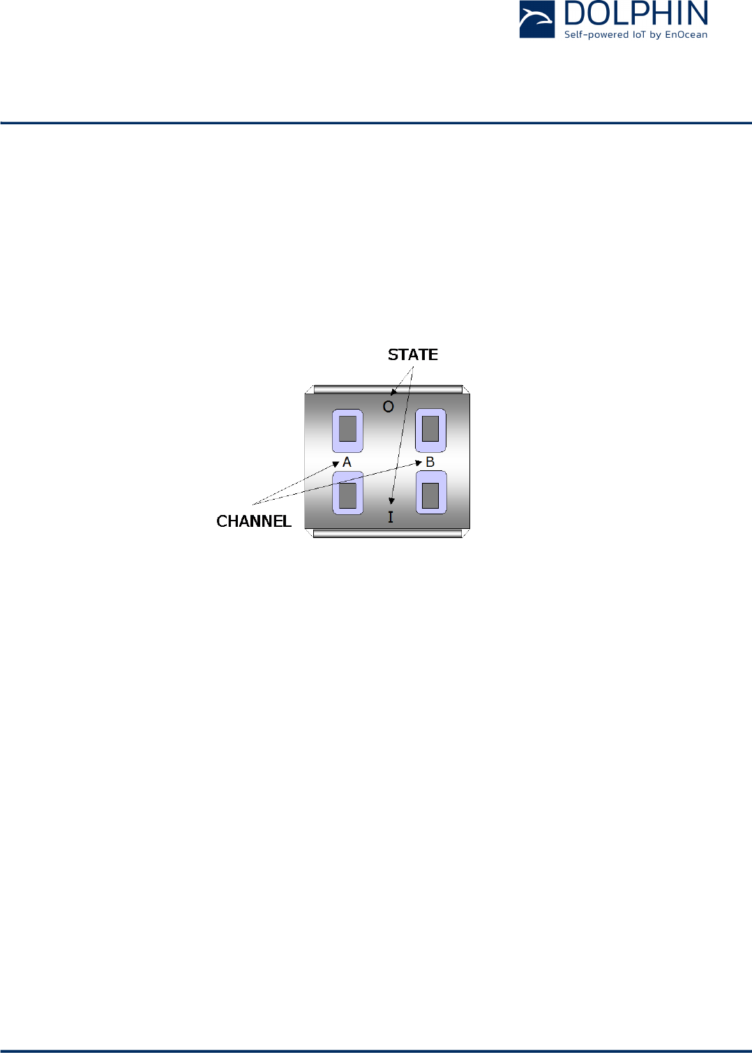
2.4 User Interface
PTM 215B devices provide four button contacts. They are grouped into two channels
(Channel A and Channel B) each containing two button contacts (State O and State I).
The state of all four button contacts (pressed or not pressed) is transmitted together with a
unique device identification (48 Bit device ID) whenever the energy bow is pushed or re-
leased.
Figure 4 below shows the arrangement of the four button contacts and their designation:
Figure 4 – Button contact designation
USER MANUAL
PTM 215B – 2.4 GHZ Pusbutton Transmitter Module
© 2016 EnOcean | www.enocean.com F-710-017, V1.0 PTM 215B User Manual | v0.8 | September 2016 | Page 10/42
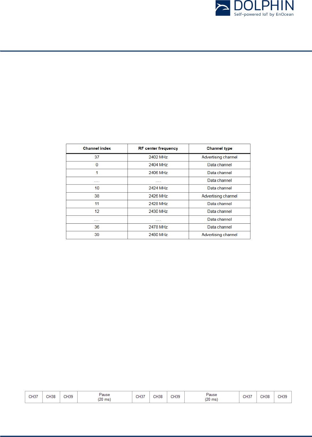
2.5 PTM 215B radio channel parameters
PTM 215B transmits advertising telegrams within the 2.4 GHz radio frequency band
(2402MHz … 2482MHz) using the BLE advertising frame format.
By default, PTM 215B will use the three BLE advertising channels (Channel 37, 38 and 39)
defined for transmission.
Table 1 below summarizes the radio channel assignment within the BLE standard.
Table 1 – Radio channel parameters
The transmission of a radio telegram on all three advertising channels is called an Advertis-
ing Event. In order to further increase communication reliability, more than one Advertising
Event might be transmitted for an individual radio telegram.
2.5.1 PTM 215B radio transmission sequence
PTM 215B transmits radio telegrams using so-called Advertising Events.
An advertising event is defined as the transmission of the same radio telegram on all se-
lected radio channels (by default this would be on BLE Channel 37, 38 and 39) one after
another with minimum delay in between.
For reliability reasons, PTM 215B will send several (minimum two, maximum three) adver-
tising events for each button input. The resulting transmission sequence is shown in Figure
5 below.
Figure 5 – Radio transmission sequence
USER MANUAL
PTM 215B – 2.4 GHZ Pusbutton Transmitter Module
© 2016 EnOcean | www.enocean.com F-710-017, V1.0 PTM 215B User Manual | v0.8 | September 2016 | Page 11/42
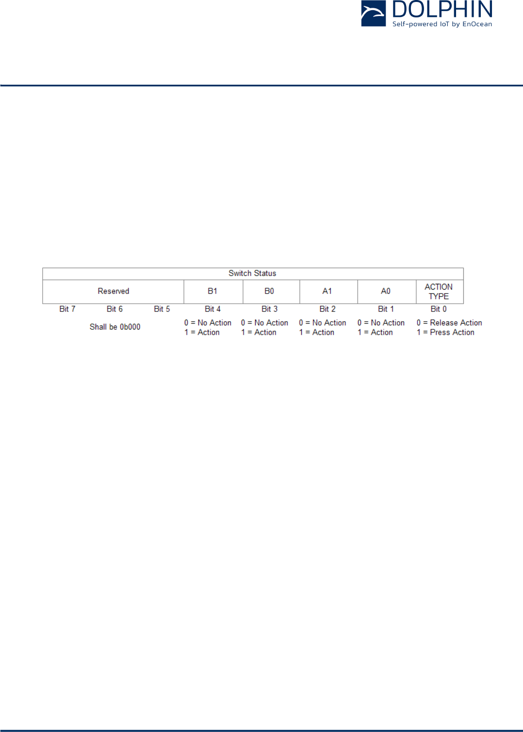
2.6 PTM 215B button action encoding
Figure 6 below shows the button action encoding used by PTM 215B.
In PTM 215B, the type of action (Press Action or Release Action) is indicated by Bit 0 (Ener-
gy Bar). If a button contact has been actuated during Press Action or Release Action then
this is indicated by the according status bit set to ‘1’.
Note that all contacts that were pressed during Press Action will be released during Release
Action. The case of continuing to hold one (or several) button contacts during Release Ac-
tion is mechanically not possible.
Figure 6 - PTM 215B button action encoding

USER MANUAL
PTM 215B – 2.4 GHZ Pusbutton Transmitter Module
© 2016 EnOcean | www.enocean.com F-710-017, V1.0 PTM 215B User Manual | v0.8 | September 2016 | Page 12/42
2.7 PTM 215B commissioning
Commissioning is the process by which PTM 215B is learned into a receiver (actuator, con-
troller, gateway, etc.).
The following two tasks are required in this process:
n Device identification
The receiver needs to know how to uniquely identify this specific PTM 215B device. This
is achieved by using a unique 48 Bit ID (Source Address) for each PTM 215B device as
described in chapter 2.9.4. In addition, up to 4 byte of Optional Data can be configured
as described in chapter 2.11.4.1
n Security parameter exchange
The receiver needs to be able to authenticate radio telegrams from PTM 215B in order to
ensure that they originate from this specific device and have not been modified as de-
scribed in chapter 2.10. This is achieved by exchanging the 128 Bit random security key
used by PTM 215B to authenticate its radio telegrams.
PTM 215B provides the following options for these tasks:
n NFC-based commissioning
The PTM 215B parameters are read by a suitable commissioning tool (e.g. NFC
smartphone) which is already part of the network into which PTM 215B will be commis-
sioned. The commissioning tool then communicates these parameters to the intended
receiver of PTM 215B radio telegrams. NFC-based commissioning is described in chapter
2.11
n Radio-based commissioning
PTM 215B can communicate its parameters via special radio telegrams (commissioning
telegrams) to the intended receiver. To do so, PTM 215B can be temporarily placed into
radio-based commissioning mode as described in chapter 2.8.2
n Camera-based commissioning
Each PTM 215B module contains an automatically readable Data Matrix Code (DMC)
which identifies its ID and its security key. This DMC can be read by a by a suitable
commissioning tool (e.g. smartphone) which is already part of the network into which
PTM 215B will be commissioned. The commissioning tool then communicates these pa-
rameters to the intended receiver of PTM 215B radio telegrams. The DMC structure is
described in chapter 3.3.1

USER MANUAL
PTM 215B – 2.4 GHZ Pusbutton Transmitter Module
© 2016 EnOcean | www.enocean.com F-710-017, V1.0 PTM 215B User Manual | v0.8 | September 2016 | Page 13/42
2.8 Operation modes
PTM 215B can operate in two modes:
n Data mode
Data mode is used to transmit data telegrams reporting the status of PTM 215B button
inputs
n Radio-based commissioning mode
Radio-based commissioning mode is used to commission (teach-in) PTM 215B into a
specific receiver or network by means of a specific commissioning telegram.
This is an alternative for scenarios where NFC commissioning cannot be used.
2.8.1 Data mode
Data mode is the standard mode of operation. In this mode, PTM 215B will transmit radio
telegrams identifying the status of its four button contacts and the energy bar.
PTM 215B uses the following sequence to identify and transmit button contact status:
1. Determine direction of the energy bar movement (Push Action or Release Action)
2. Read input status of all button contacts
3. Calculate data payload
4. Calculate security signature
5. Format BLE radio telegram
6. Transmit BLE radio telegram as sequence of Advertising Events
USER MANUAL
PTM 215B – 2.4 GHZ Pusbutton Transmitter Module
© 2016 EnOcean | www.enocean.com F-710-017, V1.0 PTM 215B User Manual | v0.8 | September 2016 | Page 14/42
2.8.2 Radio-based commissioning mode
Radio-based commissioning mode is used to associate PTM 215B with other devices. To do
so, PTM 215B can transmit a dedicated commissioning telegram (as described in chapter
2.9.6.2) identifying its relevant parameters. The commissioning telegram will be transmit-
ted on the BLE advertising channels (Channels 37, 38 and 39)
Radio-based commissioning mode is intended for applications where NFC commissioning
(as described in chapter 2.11) cannot be used.
Radio-based commissioning can be disabled by setting the Disable Radio Commissioning
flag in the Configuration register to 0b1 (see chapter 2.11.4.2).
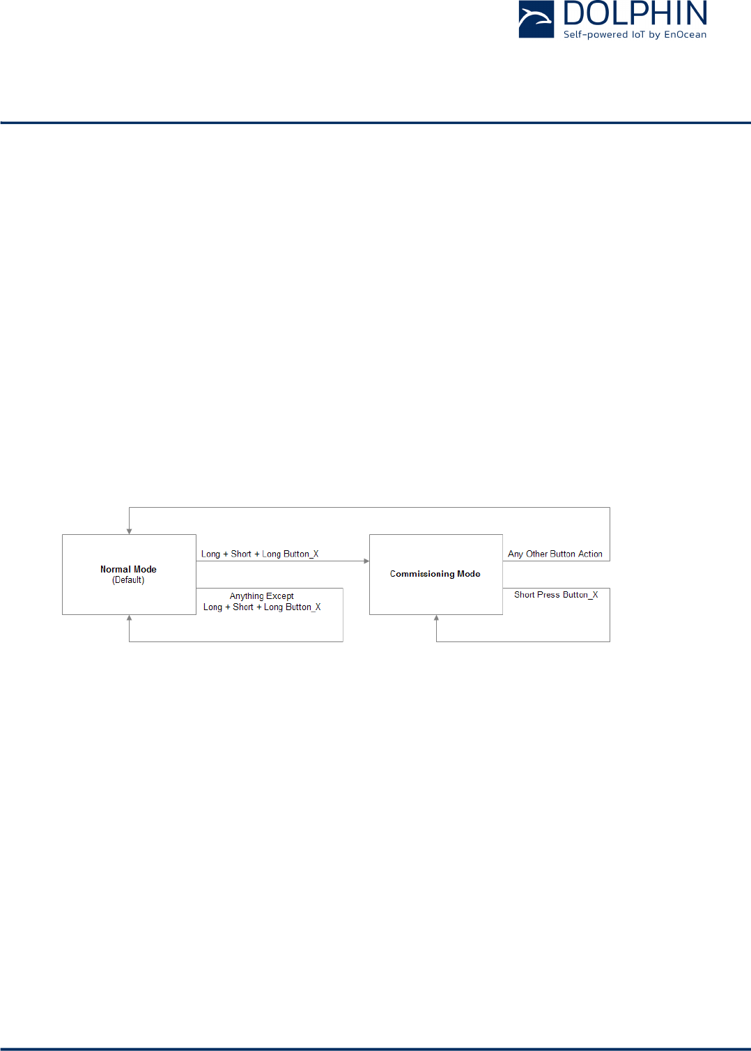
2.8.2.1 Commissioning mode entry
Commissioning mode is entered using a special button contact sequence. This is illustrated
in Figure 7 below.
Figure 7 – Button sequence for commissioning mode
To enter commissioning mode, start by selecting one button contact of PTM 215B. Any con-
tact of PTM 215B (A0, A1, B0, B1) can be used. This contact is referred to as Button_X in
Figure 7 above.
Next, execute the following long-short-long sequence:
1. Press and hold the selected button contact together with the energy bar for more
than 7 seconds before releasing it
2. Press the selected button contact together with the energy bar quickly (hold for less
than 2 seconds)
3. Press and hold the selected button contact together with the energy bar again for
more than 7 seconds before releasing it
Upon detection of this sequence, PTM 215B will enter commissioning mode if the Disable
Radio Commissioning flag in the configuration register is not set.

USER MANUAL
PTM 215B – 2.4 GHZ Pusbutton Transmitter Module
© 2016 EnOcean | www.enocean.com F-710-017, V1.0 PTM 215B User Manual | v0.8 | September 2016 | Page 15/42
2.8.2.2 Commissioning telegram transmission
PTM 215B will transmit a commissioning telegram (as sequence of Advertising Events on
the BLE advertising channels as described in chapter 2.5) upon entering commissioning
mode.
The format of the commissioning telegram is described in chapter 2.9.6.2.
PTM 215B will continue to transmit commissioning telegrams whenever the button used for
entry into commissioning mode (Button_X) is pressed or released again.
2.8.2.3 Exit from commissioning mode
Pressing any key except the button used for entry into commissioning mode (Button_X) will
cause PTM 215B to exist commissioning mode and return to normal data mode.
USER MANUAL
PTM 215B – 2.4 GHZ Pusbutton Transmitter Module
© 2016 EnOcean | www.enocean.com F-710-017, V1.0 PTM 215B User Manual | v0.8 | September 2016 | Page 16/42
2.9 BLE frame structure
PTM 215B transmits radio telegrams in the 2.4 GHz band according to BLE frame structure.
For detailed information about the BLE standard, please refer to the applicable specifica-
tions.
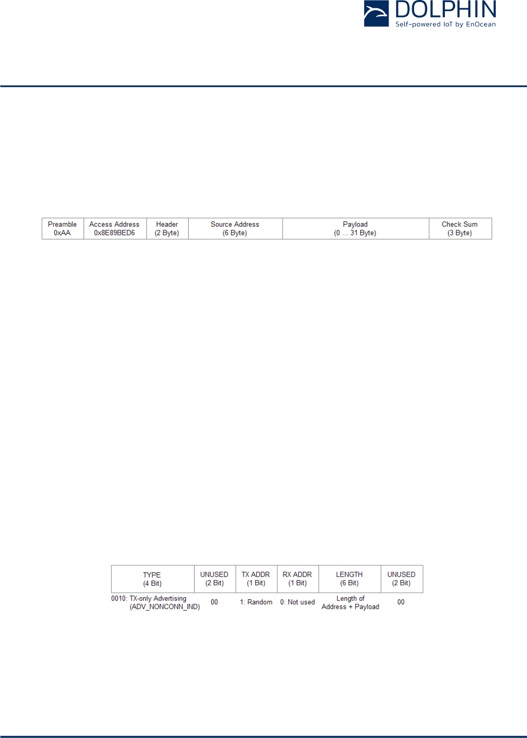
Figure 8 below summarizes the BLE frame structure.
Figure 8 – BLE frame structure
The content of these fields is described in more detail below.
2.9.1 Preamble
The BLE Preamble is 1 byte long and identifies the start of the BLE frame. The value of the
BLE Preamble is always set to 0xAA.
2.9.2 Access Address
The 4 byte BLE Access Address identifies the radio telegram type. For advertising frames,
the value of the Access Address is always set to 0x8E89BED6.
2.9.3 Header
The BLE Header identifies certain radio telegram parameters. Figure 9 below shows the
structure of the BLE header.
Figure 9 – BLE header structure
USER MANUAL
PTM 215B – 2.4 GHZ Pusbutton Transmitter Module
© 2016 EnOcean | www.enocean.com F-710-017, V1.0 PTM 215B User Manual | v0.8 | September 2016 | Page 17/42
2.9.4 Source address
The 6 byte BLE Source Address (MAC address) uniquely identifies each PTM 215B product.
PTM 215B supports two source address modes:
n Static Source Address mode (default)
In this mode, the source address is constant (but can be configured via NFC interface)
n Private Resolvable Address mode (NFC configurable)
In this mode, the source address changes for each transmission
PTM 215B uses by default the Static Source Address mode. The Private Resolvable Address
mode can be selected by setting the Private Source Address flag in the Configuration regis-
ter (see chapter 2.11.4.2) to 0b0.
These two address modes are described in the following chapters.
2.9.4.1 Static source address mode
By default, PTM 215B uses static source addresses meaning that the source address is con-
stant during normal operation. The static source address can be read and configured (writ-
ten) via NFC as described in chapter 2.11.
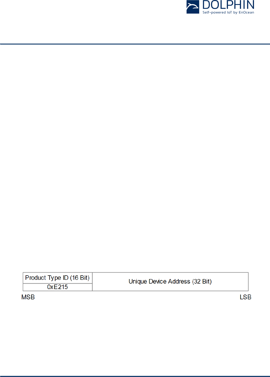
The structure of PTM 215B static addresses is as follows:
n The upper 2 bytes of the source address are used to identify the device type and set to
0xE215 for all PTM 215B devices (to designate EnOcean PTM 215 device type).
n The lower 4 bytes are uniquely assigned to each device.
Figure 10 below illustrates the static address structure used by PTM 215B.
Figure 10 – BLE static source address structure
USER MANUAL
PTM 215B – 2.4 GHZ Pusbutton Transmitter Module
© 2016 EnOcean | www.enocean.com F-710-017, V1.0 PTM 215B User Manual | v0.8 | September 2016 | Page 18/42
2.9.4.2 Private resolvable source address mode
For some applications it is desirable to modify (rotate) the source address used by PTM
215B in order to prevent tracking of its radio transmissions. At the same time, each PTM
215B device must remain uniquely identifiable by the receiver.
To achieve these goals, PTM 215B can be configured via NFC to use random resolvable pri-
vate addresses.
Using random resolvable private addresses requires that both PTM 215B and the receiver
both know a common key – the so-called Identity Resolution Key (IRK). PTM 215B uses its
device-unique random key as identity resolution key. This key can be configured via NFC
as described in chapter 2.11.
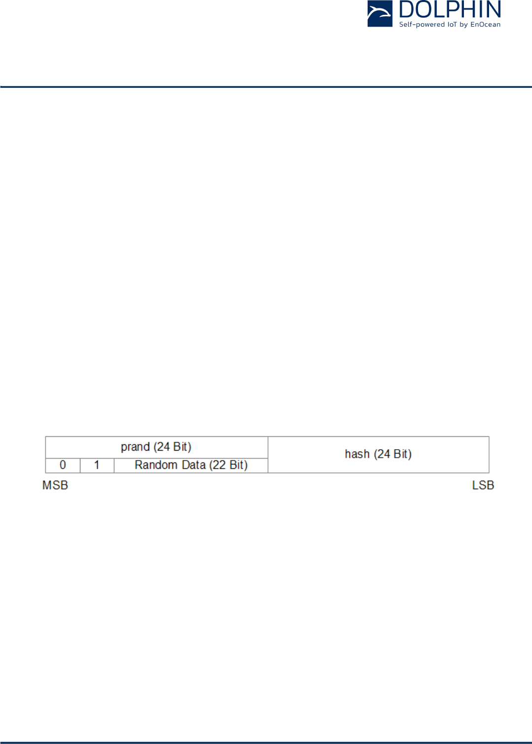
For resolvable private addresses, the 48 bit address field is split into two sub-fields:
n prand
This field contains a random number which always starts (two most significant bits) with
0b10. The prand value is changed for each telegram that is transmitted. Individual ad-
vertising events used to transmit one telegram (as described in chapter 2.5.1) use the
same prand value.
n hash
This field contains a verification value (hash) generated from prand using the IRK
The structure of a random resolvable private address is shown in Figure 11 below.
Figure 11 – BLE private resolvable source address structure
The prand value is encrypted using the IRK. The lowest 24 bit of the result (encrypted val-
ue) are then used as hash.
The concatenation of 24 bit prand and 24 bit hash will be transmitted as 48 bit private re-
solvable source address.
USER MANUAL
PTM 215B – 2.4 GHZ Pusbutton Transmitter Module
© 2016 EnOcean | www.enocean.com F-710-017, V1.0 PTM 215B User Manual | v0.8 | September 2016 | Page 19/42
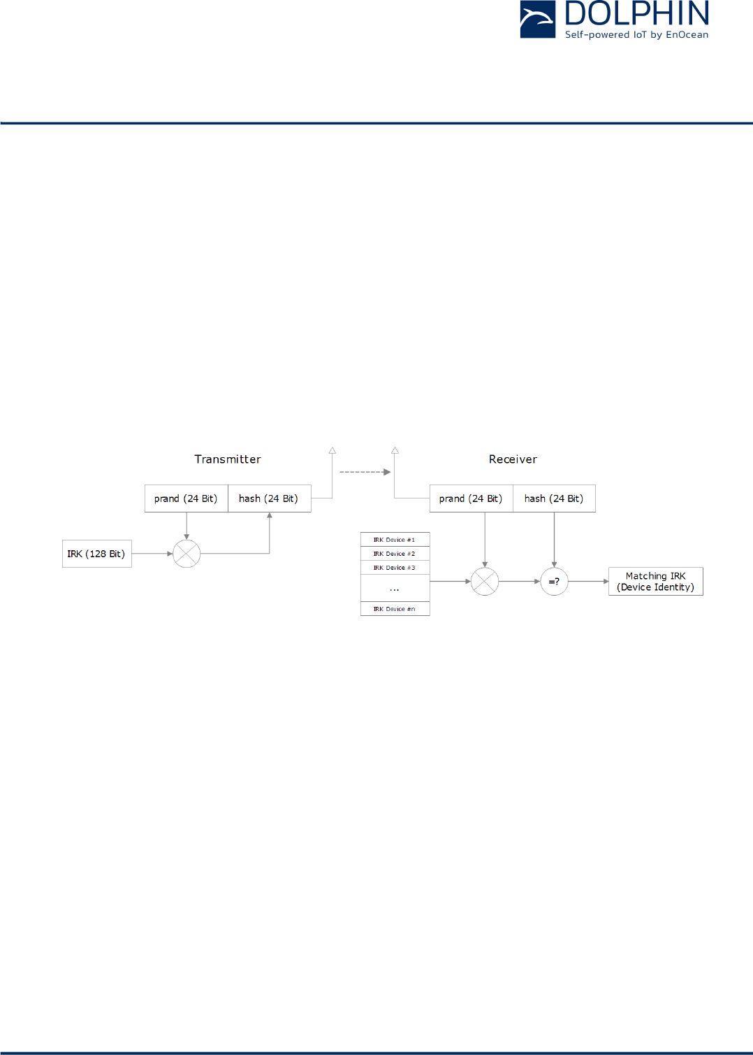
The receiving device maintains a list of IRK for all transmitters that have been commis-
sioned to work with it.
Whenever the receiving device receives a radio telegram with private resolvable source
address (identified by the most significant bits being set to 0b10), it will itself generate a 24
bit hash from the 24 bit prand sequentially using the IRK of each device that it has been
learned into it.
If an IRK matches (i.e. when prand is encoded with this specific IRK then the result match-
es hash), then the receiver has established the identity of the transmitter.
So conceptually the IRK takes the role of source ID while prand and hash provide a mecha-
nism to select the correct IRK among a set of IRK.
This mechanism is illustrated in Figure 12 below.
Figure 12 – Resolving private source addresses
2.9.5 Check Sum
The 3 byte BLE Check Sum is used to verify data integrity of received BLE radio telegrams.
It is calculated as CRC (cyclic redundancy check) of the BLE Header, Source Address and
Payload fields.
USER MANUAL
PTM 215B – 2.4 GHZ Pusbutton Transmitter Module
© 2016 EnOcean | www.enocean.com F-710-017, V1.0 PTM 215B User Manual | v0.8 | September 2016 | Page 20/42
2.9.6 Payload
The payload structure is depending on the telegram type (data telegram or commissioning
telegram).
2.9.6.1 Data Telegram Payload
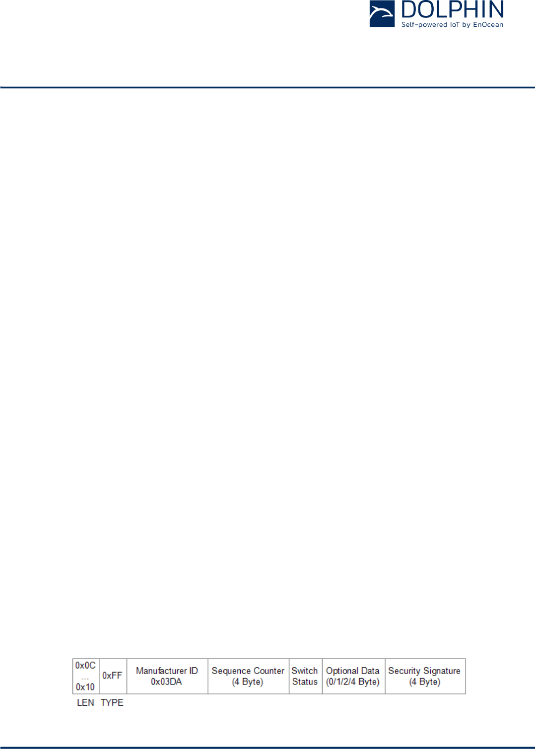
The payload of data telegrams is 13 … 17 bytes long and consists of the following fields:
n Length (1 byte)
The Length field specifies the combined length of the following fields. The content of the
field depends on the size of the Optional Data field (which can be 0 / 2 / 2 or 4 byte).
The resulting Length setting would be 12 / 13 / 14 or 16 byte (0x0C / 0x0D / 0x0E / 0x10)
respectively
n Type (1 byte)
The Type field identifies the data type used for this telegram. For PTM 215B data tele-
grams, this field is always set to 0xFF to designate manufacturer-specific data field
n Manufacturer ID (2 byte)
The Manufacturer ID field is used to identify the manufacturer of BLE devices based on
assigned numbers. EnOcean has been assigned 0x03DA as manufacturer ID code
n Sequence Counter (4 byte)
The Sequence Counter is a monotonously incrementing counter used for security pro-
cessing. It is initialized to 0 at the time of production and incremented for each telegram
(data telegram or commissioning telegram) sent.
n Switch Status (1 byte)
The Switch Status field reports the button action. The encoding of this field is described
in chapter 2.6.
n Optional Data (0 / 1 / 2 or 4 byte)
PTM 215B provides the option to transmit additional user-defined data within each data
telegram. This data can be used to identify user-specific properties.
The length of the Optional Data field is defined in the Configuration register as described
in chapter 2.11.4.2.
n Security Signature (4 byte)
The Security Signature is used to authenticate PTM 215B radio telegrams as described in
chapter 2.10
Figure 13 below illustrates the data telegram payload.
USER MANUAL
PTM 215B – 2.4 GHZ Pusbutton Transmitter Module
© 2016 EnOcean | www.enocean.com F-710-017, V1.0 PTM 215B User Manual | v0.8 | September 2016 | Page 21/42
Figure 13 – Data telegram payload structure
2.9.6.2 Commissioning Telegram Payload
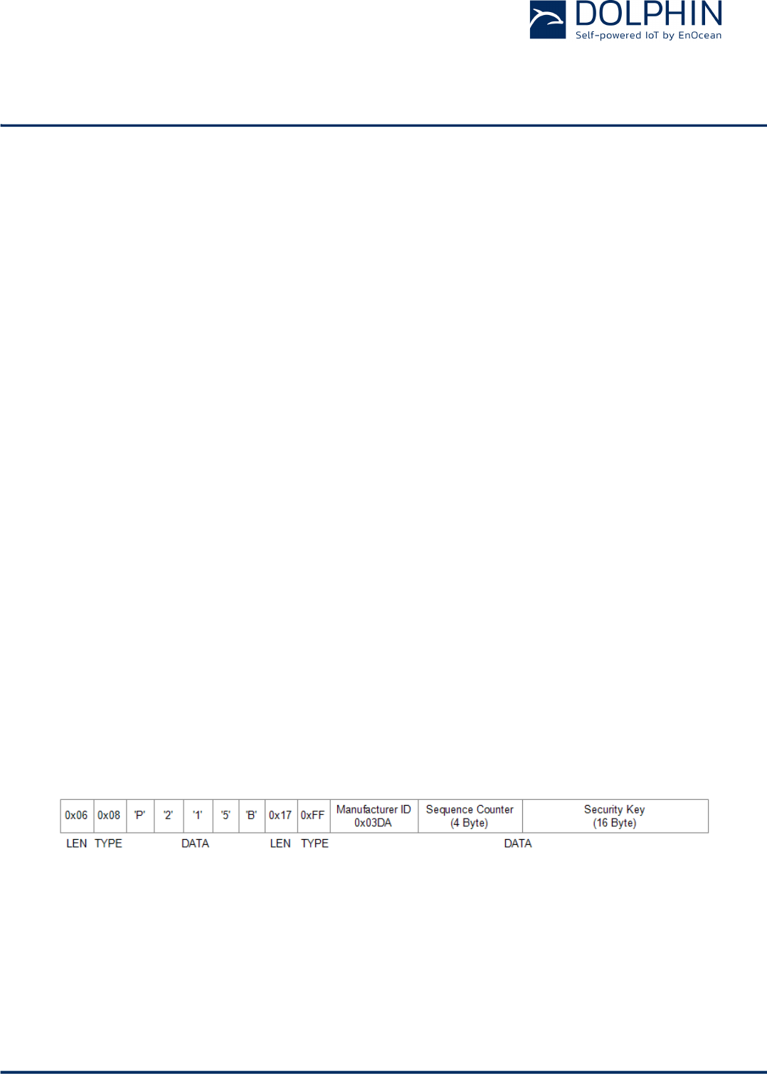
The payload of commissioning telegrams is 31 bytes long and consists of the following
fields:
n Length (1 byte)
The Length field specifies the combined length of the following fields. For PTM 215B
commissioning telegrams, this field is always set to 0x06 (6 byte) for the “Short Name”
field and to 0x17 (23 byte) for the “Manufacturer-specific Data” field
n Type (1 byte)
The Type field identifies the data type used for this telegram. For PTM 215B commission-
ing telegrams, this field is set to 0x08 for the “Short Name” field and to 0xFF for the
“Manufacturer-specific Data” field
n Short Name
The Short Name field identifies PTM 215B using the string “P215B”
n Manufacturer ID (2 byte)
The Manufacturer ID field can be used to identify the manufacturer of BLE devices based
on assigned numbers. EnOcean has been assigned 0x03DA as manufacturer ID code
n Sequence Counter (4 byte)
The Sequence Counter is a monotonously incrementing counter used for security pro-
cessing. It is initialized to 0 at the time of production and incremented for each telegram
(data telegram or commissioning telegram) sent.
n Security Key (16 byte)
Each PTM 215B device contains its own 16 byte device-unique random security key
which is generated and programmed during manufacturing. It is transmitted during
commissioning to enable the receiver to authenticate PTM 215B data telegrams
Figure 14 below illustrates the commissioning telegram payload.
Figure 14 – Commissioning telegram payload structure
USER MANUAL
PTM 215B – 2.4 GHZ Pusbutton Transmitter Module
© 2016 EnOcean | www.enocean.com F-710-017, V1.0 PTM 215B User Manual | v0.8 | September 2016 | Page 22/42
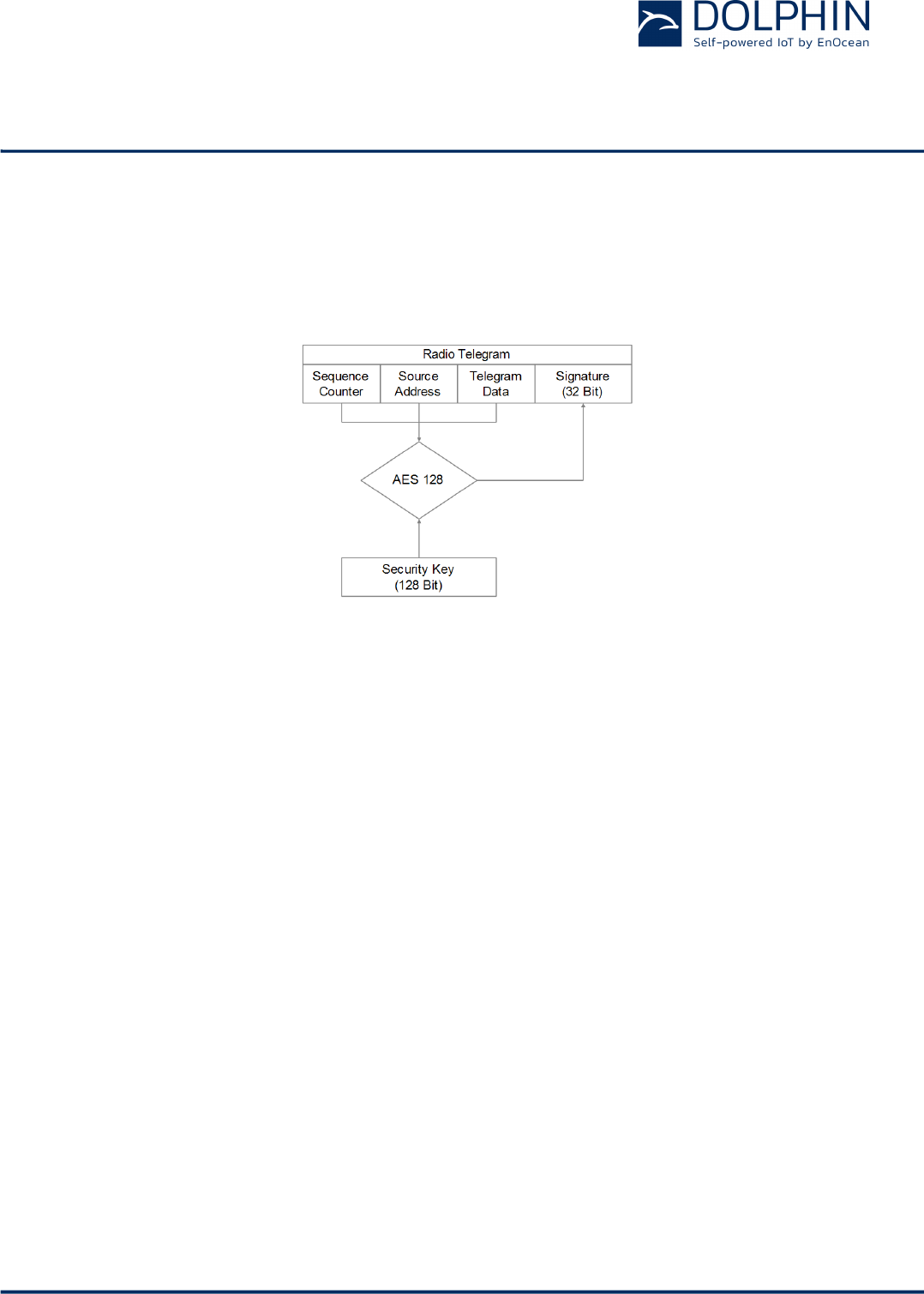
2.10 Telegram authentication
PTM 215B implements telegram authentication to ensure that only telegrams from senders
using a previously exchanged security key will be accepted. Authentication relies on a 32
bit telegram signature which is calculated as shown in Figure 15 below and exchanged as
part of the radio telegram.
Figure 15 – Telegram authentication flow
Sequence counter, source address and the remaining telegram data together form the in-
put data for the signature algorithm. This algorithm uses AES 128 encryption based on the
device-unique random security key to generate a 32 bit signature which will be transmitted
as part of the radio telegram.
The signature is therefore dependent both on the current value of the sequence counter,
the device source address and the telegram payload. Changing any of these three parame-
ters will therefore result in a different signature.
The receiver performs the same signature calculation based on sequence counter, source
address and the remaining telegram data of the received telegram using the security key it
received from PTM 215B during commissioning.
The receiver then compares the signature reported as part of the telegram with the signa-
ture it has calculated. If these two signatures match then the following statements are
true:
n Sender (PTM 215B) and receiver use the same security key
n The message content (address, sequence counter, data) has not been modified
At this point, the receiver has validated that the message originates from a trusted sender
(as identified by its security key) and that its content is valid.
In order to avoid message replay (capture and retransmission of a valid message), it is
required that the receiver tracks the value of the sequence counter used by PTM 215B and
only accepts messages with higher sequence counter values (i.e. not accepts equal or lower
sequence counter values for subsequent telegrams).
USER MANUAL
PTM 215B – 2.4 GHZ Pusbutton Transmitter Module
© 2016 EnOcean | www.enocean.com F-710-017, V1.0 PTM 215B User Manual | v0.8 | September 2016 | Page 23/42
2.10.1 Authentication implementation
PTM 215B implements telegram authentication based on AES128 in CCM (Counter with
CBC-MAC) mode as described in IETF RFC 3610.
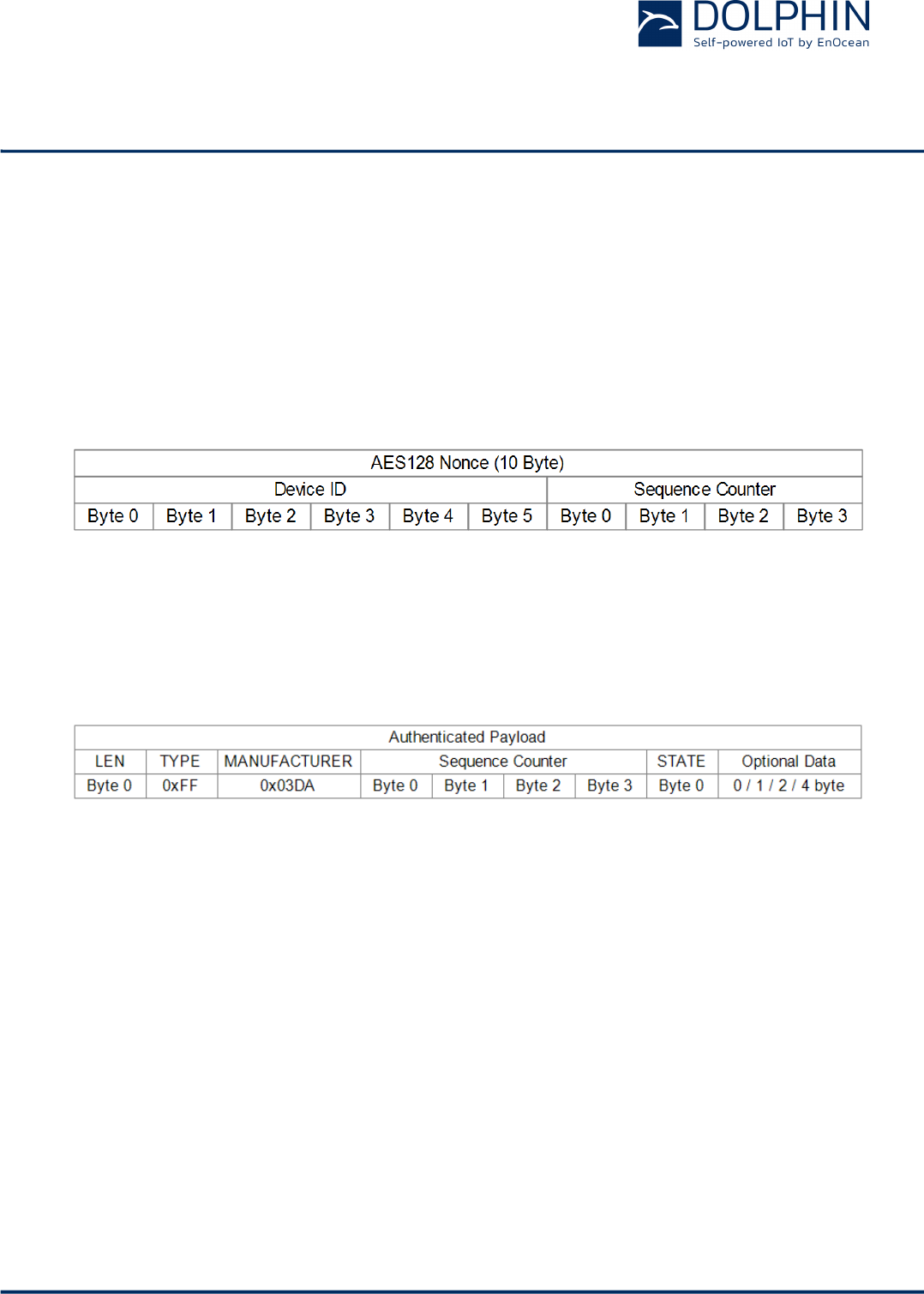
The 10 Byte CCM Nonce (number used once – unique) initialization value is constructed as
concatenation of 48 bit Device ID and 32 bit Sequence Counter in little endian format (least
significant byte first.
Figure 16 below shows the AES128 Nonce.
Figure 16 – AES128 Nonce structure
The AES128 Nonce and the 128 bit device-unique security key are then used to calculate a
32 bit signature of the telegram payload shown in Figure 17 below.
Figure 17 – Authenticated payload
The calculated 32 bit signature is then appended to the payload as shown in
Figure 13 in chapter 2.9.6.1.
USER MANUAL
PTM 215B – 2.4 GHZ Pusbutton Transmitter Module
© 2016 EnOcean | www.enocean.com F-710-017, V1.0 PTM 215B User Manual | v0.8 | September 2016 | Page 24/42
2.11 NFC interface
PTM 215B implements NFC Forum Type 2 Tag functionality as specified in the ISO/IEC
14443 Part 2 and 3 standard.
This NFC functionality can be used to access (read and write) the PTM 215B configuration
memory and thereby configure the device as described in the following chapters.
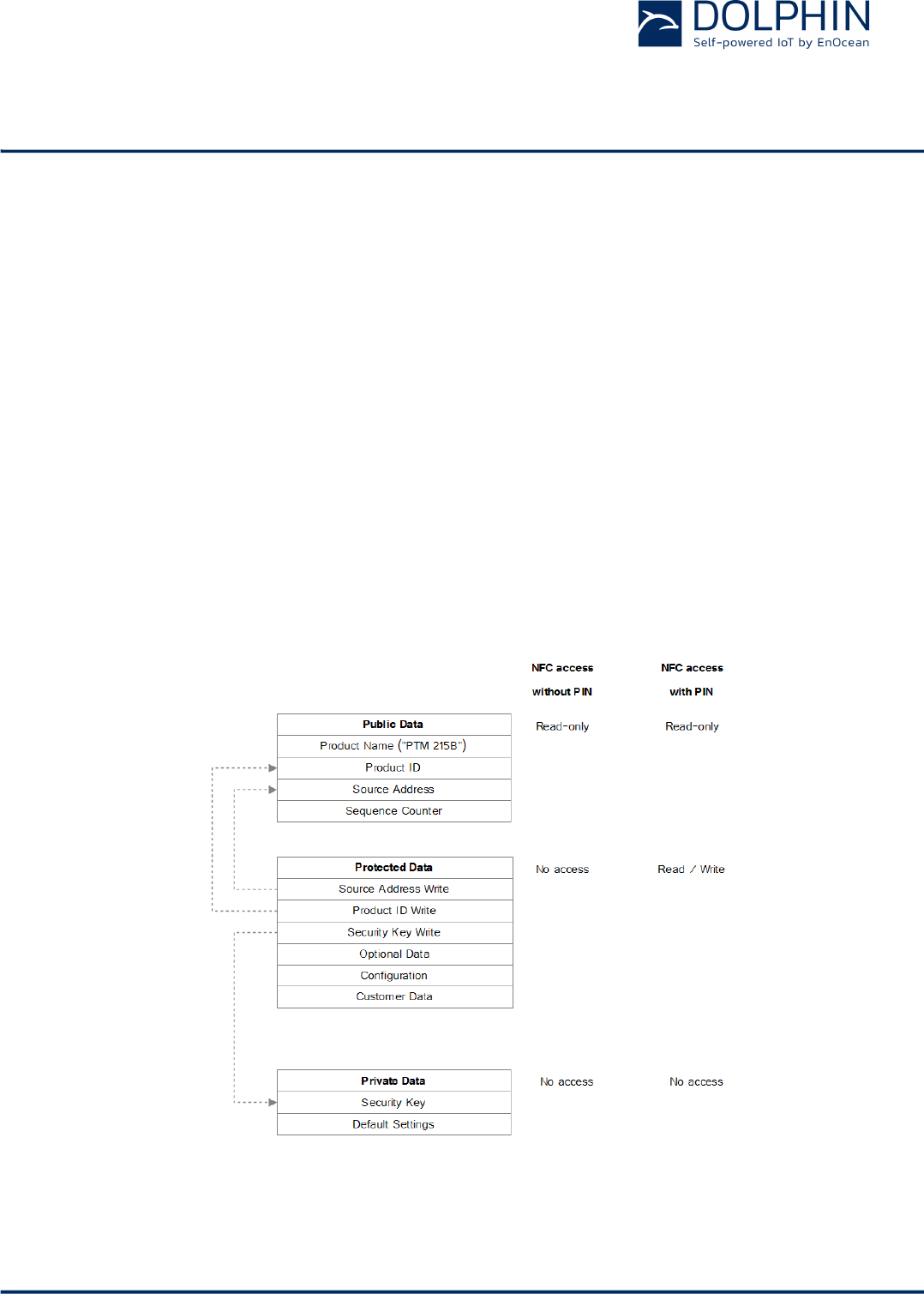
2.11.1 Configuration memory organization
The PTM 215B configuration memory is divided into the following areas:
n Public data
n Protected data
In addition to that, PTM 215B maintains a private configuration memory region used to
store default parameters and confidential information which is not accessible to the user.
Figure 18 below illustrates the configuration memory organization used by PTM 215B.
Figure 18 – Configuration memory organization
USER MANUAL
PTM 215B – 2.4 GHZ Pusbutton Transmitter Module
© 2016 EnOcean | www.enocean.com F-710-017, V1.0 PTM 215B User Manual | v0.8 | September 2016 | Page 25/42
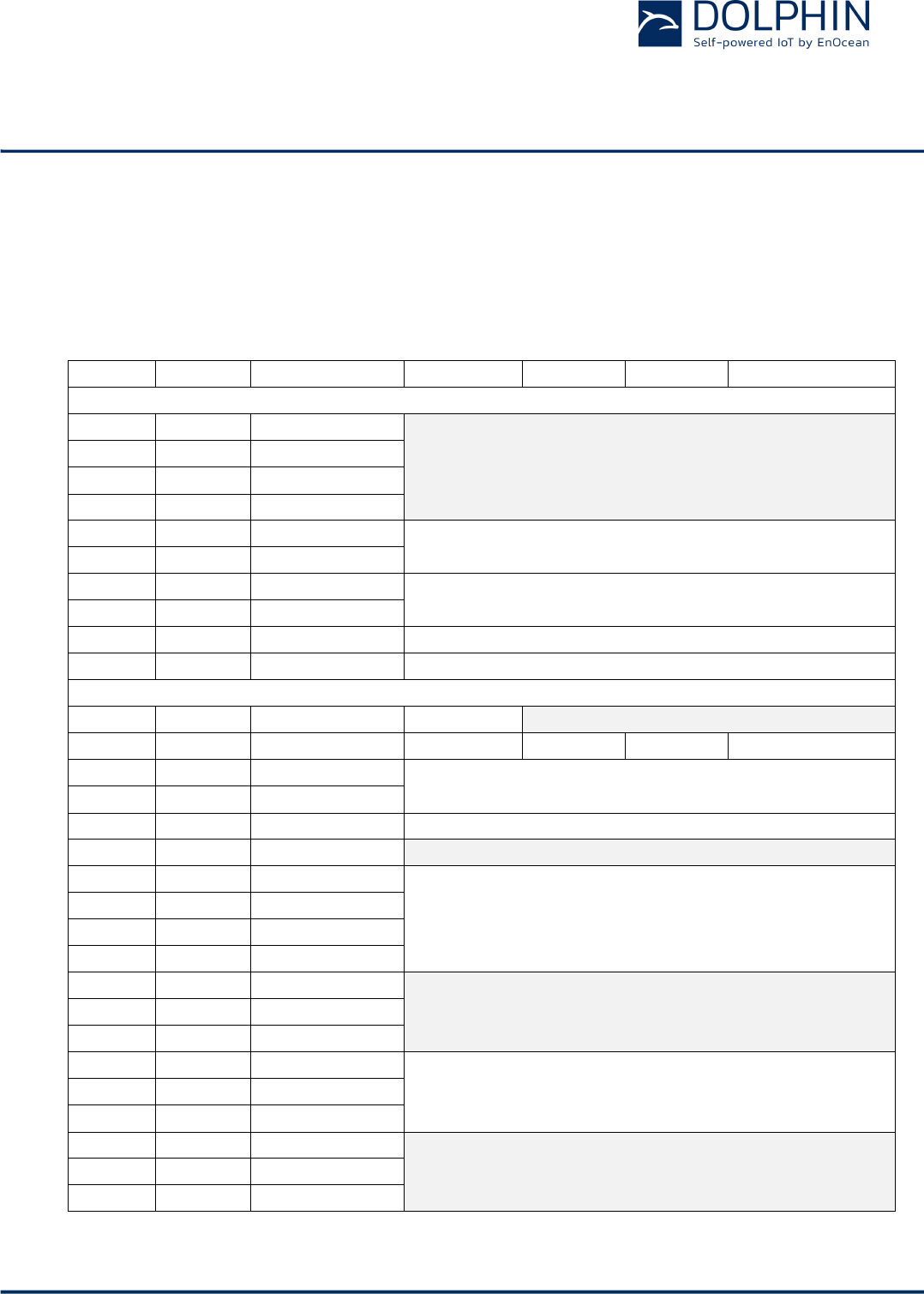
2.11.2 Memory Address Map
The NFC-accessible configuration memory is organized in memory pages where each
memory page is 4 byte wide. Each NFC access reads or writes one memory page.
The addresses map of the configuration memory is shown in Figure 19 below. The byte or-
der is little endian, i.e. Byte 0 will be read first and Byte 3 last.
Area
NFC Page
Total Byte Offset
Byte 0 (LSB)
Byte 1
Byte 2
Byte 3 (MSB)
Public Memory Area
Public
0x00
0
Reserved
Public
0x01
4
Public
0x02
8
Public
0x03
12
Public
0x04
16
Product Name "PTM 215B"
Public
0x05
20
Public
0x06
24
Product ID
Public
0x07
28
Public
0x08
32
Static Source Address
Public
0x09
36
Sequence Counter
Protected Memory Area
Protected
0x0A
40
Configuration
Reserved
Protected
0x0B
44
Opt Data 0
Opt Data 1
Opt Data 2
Opt Data 3
Protected
0x0C
48
Product ID Write
Protected
0x0D
52
Protected
0x0E
56
Source ID Write
Protected
0x0F
60
Reserved
Protected
0x10
64
Security Key Write
Protected
0x11
68
Protected
0x12
72
Protected
0x13
76
Protected
0x14
80
Reserved
Protected
…
…
Protected
0x1F
124
Protected
0x20
128
Custom NFC Data
Protected
…
…
Protected
0x5F
380
Protected
0x60
384
Reserved
Protected
…
…
Protected
0xE1
900
Figure 19 – Configuration memory address map

USER MANUAL
PTM 215B – 2.4 GHZ Pusbutton Transmitter Module
© 2016 EnOcean | www.enocean.com F-710-017, V1.0 PTM 215B User Manual | v0.8 | September 2016 | Page 26/42
2.11.3 Public data
Public data can be read by any NFC-capable device supporting the ISO/IEC 14443 Part 2
and 3 standard. No specific security measures are used to restrict read access to this data.
The following items are located in the public data area:
n PTM 215B Static Source Address (32 Bit, see chapter 2.9.4.1)
n PTM 215B Product Name (this is always “PTM 215B”)
n PTM 215B Product ID (up to 8 characters, to be assigned by the user)
n Telegram sequence counter (initialized to 0 during manufacturing and incremented for
each transmitted telegram)
Changing the Static Source Address and Product ID fields is only possible via protected data
access as described below to prevent unauthorized modification.
For security reasons, the telegram sequence counter cannot be written or reset by any
mechanism.
2.11.4 Protected Data
The following items are located in the protected data area:
n Source Address Write register
n Product ID Write register
n Security Key Write register
n Optional Data register
n Configuration register
n Customer Data

USER MANUAL
PTM 215B – 2.4 GHZ Pusbutton Transmitter Module
© 2016 EnOcean | www.enocean.com F-710-017, V1.0 PTM 215B User Manual | v0.8 | September 2016 | Page 27/42
2.11.4.1 PIN Code
Protected data access is only possible after unlocking the configuration memory with the
correct 32 bit PIN code.
By default, the protected area is locked and the default pin code for unlocking access is
0x0000E215. This pin code should be changed to a user-defined value as part of any NFC-
based installation process.
2.11.4.1 Modifying product parameters
Modifying (writing) PTM 215B the following product parameters is not directly possible:
n Static Source Address
n Product ID
n Security Key
In order to modify these parameters, the user has to write the new value into specific reg-
isters (Source Address Write, Product ID Write and Security Key Write) in the protected
data area and set the according Update flag in the Configuration register.
2.11.4.2 Source Address Write register
The Source Address Write register is 6 byte wide and can be used to modify the PTM 215B
source address.
In order to do so, follow these steps:
1. Write new source address into the Source Address Write register
2. Set the Update Source Address flag in the Configuration register to 0b1
3. Actuate (press and release) PTM 215B
PTM 215B will determine that it should modify the source address based on the setting of
the Update Source Address flag and copy the value of the Source Address Write register to
the Source Address register.
After successful execution, PTM 215B will clear the Update Source Address flag to 0b0.

USER MANUAL
PTM 215B – 2.4 GHZ Pusbutton Transmitter Module
© 2016 EnOcean | www.enocean.com F-710-017, V1.0 PTM 215B User Manual | v0.8 | September 2016 | Page 28/42
2.11.4.3 Security Key Write register
The Security Key Write register is 16 byte wide and contains the device-unique random
security key.
The factory programmed key can be replaced with a user defined key by following these
steps:
1. Write new security key into the Security Key Write register
Note that for security reasons, setting the Security Key to the following values is not
possible:
• 0x00000000000000000000000000000000
• 0xFFFFFFFFFFFFFFFFFFFFFFFFFFFFFFFF
If the Security Key Write register is set to one of these values then no update of the
Security Key will occur.
2. Set the Update Security Key flag in the Configuration register to 0b1
3. If the key should be write-only (not readable after the key update) then set the Pri-
vate Security Key flag in the Configuration register to 0b1
4. Actuate (press and release) PTM 215B
PTM 215B will determine that it should modify the security key based on the setting of the
Update Security Key flag and copy the value of the Security Key Write register to the Secu-
rity Key register in private memory.
After successful execution, PTM 215B will clear the Update Security Key flag to 0b0.
If the Private Key flag in the Configuration register is set to 0b0 then the content of the Se-
curity Key Write register will be maintained at its current value. This addresses use cases
where the security key shall be readable for users having the correct PIN code.
If the Private Key flag in the Configuration register is set to 0b1 then the content of the Se-
curity Key Write register will be cleared to 0x00000000000000000000000000000000 after suc-
cessful execution. This addresses use cases where the security key shall never be readable
(even for users having the correct PIN code). The Security Key Write register will maintain
this value of 0x00000000000000000000000000000000 even if the Private Key flag in the Con-
figuration register is subsequently cleared to 0b0. This ensures that it is not possible to
read a security key which was written with the If the Private Key flag in the Configuration
register being set.
Note that it is not possible to read the current security key via NFC if the Security Key Write
register has been accidentally overwritten or cleared via NFC write. In this case it is neces-
sary to write a new security key (as described above) or to reset the device to its default
security key by means of a factory reset.
The protected memory is designed to support 1000 modifications of the security key.

USER MANUAL
PTM 215B – 2.4 GHZ Pusbutton Transmitter Module
© 2016 EnOcean | www.enocean.com F-710-017, V1.0 PTM 215B User Manual | v0.8 | September 2016 | Page 29/42
2.11.4.4 Product ID Write register
The Product ID register is 8 byte wide and can be used to specify a publicly-accessible pa-
rameter (e.g. a user-specific ID or name).
In order to do so, follow these steps:
1. Write new product ID (using ASCII encoding) into the Product ID Write register.
2. Set the Update Product ID flag in the Configuration register to 0b1
3. Actuate (press and release) PTM 215B
PTM 215B will determine that it should update the short name based on the setting of the
Update Product ID flag and copy the value of the Product ID Write register to the Product
ID register.
After successful execution, PTM 215B will clear the Update Product ID flag to 0b0.
2.11.4.1 Optional Data register
The Optional Data register can be used to specify up to 4 byte of custom data that will be
transmitted as part of each data telegram. This optional data can store user-specific or ap-
plication-specific information.
The size of the Optional Data field is specified in the Configuration register and can be 0
byte (not present, default), 1 byte, 2 byte or 4 byte.
If the size of the Optional Data field is set to a non-zero value in the Configuration register
then PTM 215B will read the corresponding amount of data from the Optional Data register
beginning with the least significant byte (Byte 0).
Note that using the Optional Data feature requires additional energy for the radio telegram
transmission and might therefore reduce the total number of redundant telegrams which
are transmitted.
USER MANUAL
PTM 215B – 2.4 GHZ Pusbutton Transmitter Module
© 2016 EnOcean | www.enocean.com F-710-017, V1.0 PTM 215B User Manual | v0.8 | September 2016 | Page 30/42
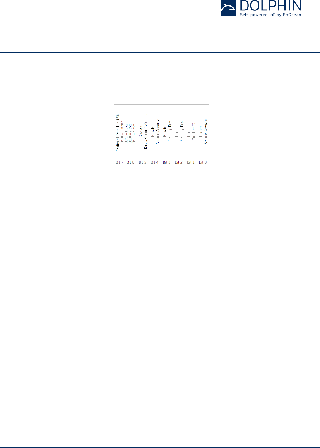
2.11.4.2 Configuration register
The Configuration register is 1 byte wide and contains configuration flags. Figure 20 below
shows the structure of the Configuration register.
Figure 20 – Configuration register structure
2.11.4.3 Customer Data
PTM 215B allocates 64 pages (256 byte) for customer data that can be read and written via
the NFC interface in protected mode.
The main intention is to enable storing OEM-specific information such as product type, revi-
sion, date code or similar. There is however no restriction (other than the maximum size of
256 byte) on the type of content that can be stored in this memory region.
PTM 215B will not access or modify this memory region.
Users should keep in mind that the content of this memory region will not be affected by a
factory reset. This means that after a factory reset, the content of this memory region can
be read using the default PIN code. This region should therefore not be used to store sensi-
tive data.

USER MANUAL
PTM 215B – 2.4 GHZ Pusbutton Transmitter Module
© 2016 EnOcean | www.enocean.com F-710-017, V1.0 PTM 215B User Manual | v0.8 | September 2016 | Page 31/42
2.11.5 Private Data
The private data area stores the following items:
n Security Key
n Default settings
The content of the private data area is not externally accessible.
2.11.5.1 Security Key
The Security Key field contains the 128-Bit key used for authenticating PTM 215B telegrams
and for resolving private source addresses.
2.11.5.2 Default Settings
The Default Settings field contains a backup of the following PTM 215B factory settings:
n Source Address
n Security Key
n NFC PIN Code
These default settings can be restored by means of a factory reset as described in chapter
2.12 below.

USER MANUAL
PTM 215B – 2.4 GHZ Pusbutton Transmitter Module
© 2016 EnOcean | www.enocean.com F-710-017, V1.0 PTM 215B User Manual | v0.8 | September 2016 | Page 32/42
2.12 Factory Reset
PTM 215B can be reset to its default settings by means of a factory reset.
This ensures that PTM 215B can be reset to a known configuration in case the PIN for the
NFC access has been lost or NFC access is not possible for other reasons
In order to execute such factory reset, the rocker(s) and the switch housing have to be
removed from the PTM 215B module. Then, all four button contacts (A0, A1, B0 and B1)
have to be pressed at the same time while the energy bow is pressed down.
The energy bow must then be held at the down position for at least 10 seconds before be-
ing released. The button contacts A0, A1, B0 and B1 can be released at any time after
pressing the energy bow down, i.e. it is no requirement to hold them as well for at least 10
seconds.
Upon detecting this input, PTM 215B will restore the default settings of the following items:
n Source Address
n Security Key and Security Key Write register
Both registers will be restored to the value of the factory-programmed security key
n NFC PIN Code
After such factory reset, Source Address and Security Key will again match the content of
the DMC code on the unit label as described in chapter 3.3.
In addition, PTM 215B will reset the following register:
n Configuration register (to 0x00)
USER MANUAL
PTM 215B – 2.4 GHZ Pusbutton Transmitter Module
© 2016 EnOcean | www.enocean.com F-710-017, V1.0 PTM 215B User Manual | v0.8 | September 2016 | Page 33/42
3 Device Integration
PTM 215B is designed for integration into button or rocker based switches. It implements
the established PTM 2xx mechanical form factor and can therefore be used with a wide va-
riety of existing designs.
3.1 Mechanical Interface Characteristics
Energy bow travel / o
perating force 1.8 mm / typ. 10
N
At room temperature
Only one of the two energy bows may be actuated at the same time!
Restoring force at energy bow
typ. 0.7 N
Minimum restoring force of 0.5 N is required for correct operation
Number of operations at 25°C typ. 100.000 actuations tested according to VDE 0632 / EN 60669
Cover material Hostaform (POM)
Energy bow material PBT (50% GV)
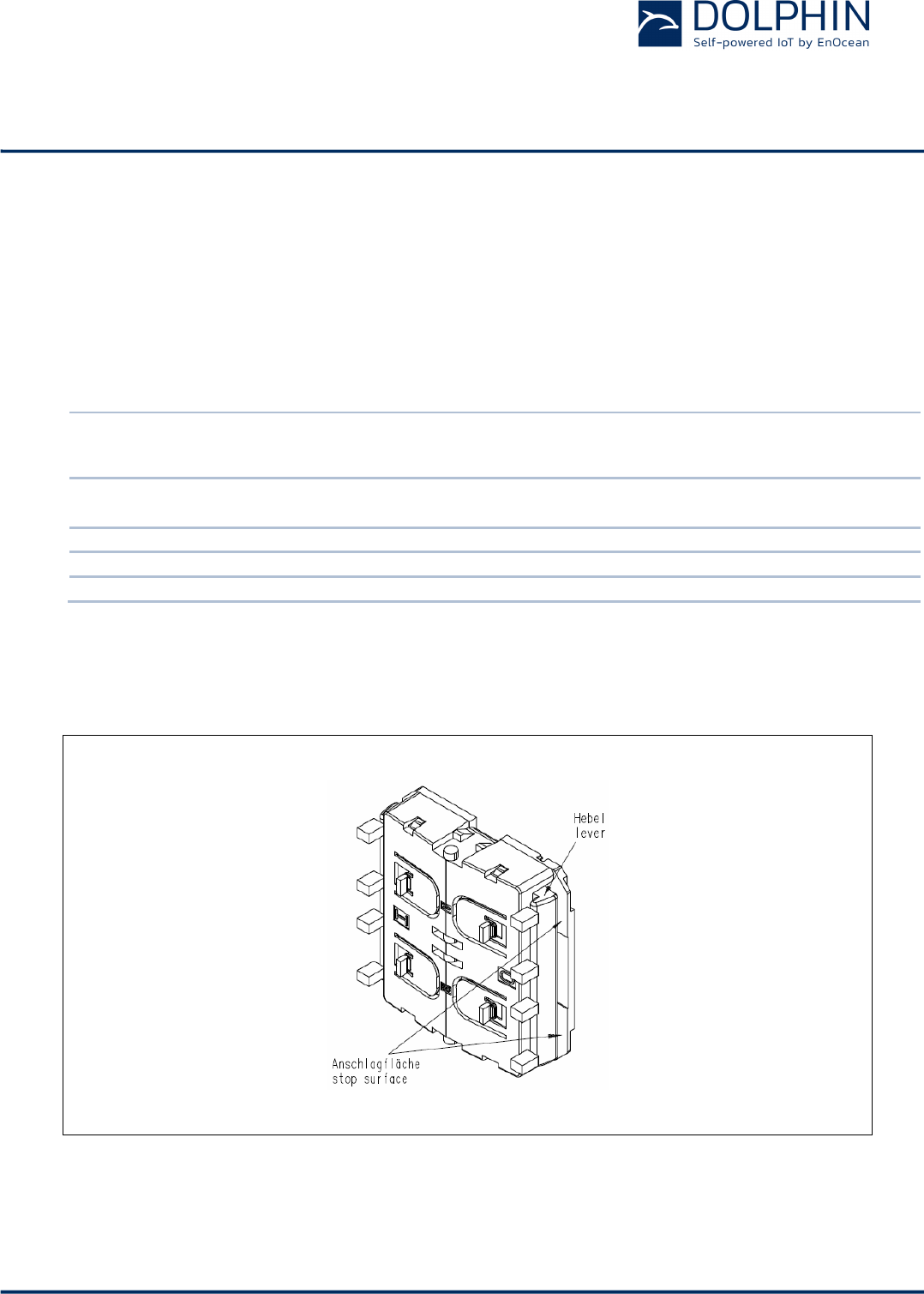
3.2 Mechanical Interface Drawings
Figure 21 – PTM 215B, tilted view (including rocker catwalks)
USER MANUAL
PTM 215B – 2.4 GHZ Pusbutton Transmitter Module
© 2016 EnOcean | www.enocean.com F-710-017, V1.0 PTM 215B User Manual | v0.8 | September 2016 | Page 34/42
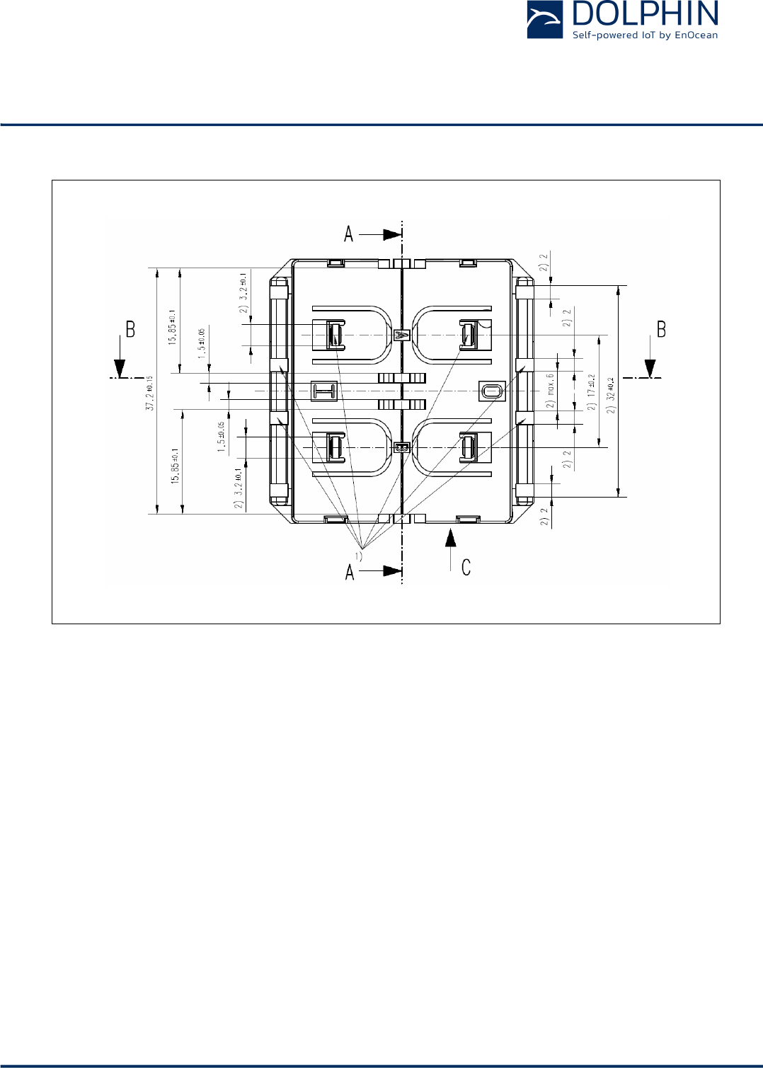
1) these catwalks are not needed when using one single rocker only 2) dimensions of rocker part
Figure 22 – PTM 215B, top view (note cut A, B and C marking)
USER MANUAL
PTM 215B – 2.4 GHZ Pusbutton Transmitter Module
© 2016 EnOcean | www.enocean.com F-710-017, V1.0 PTM 215B User Manual | v0.8 | September 2016 | Page 35/42
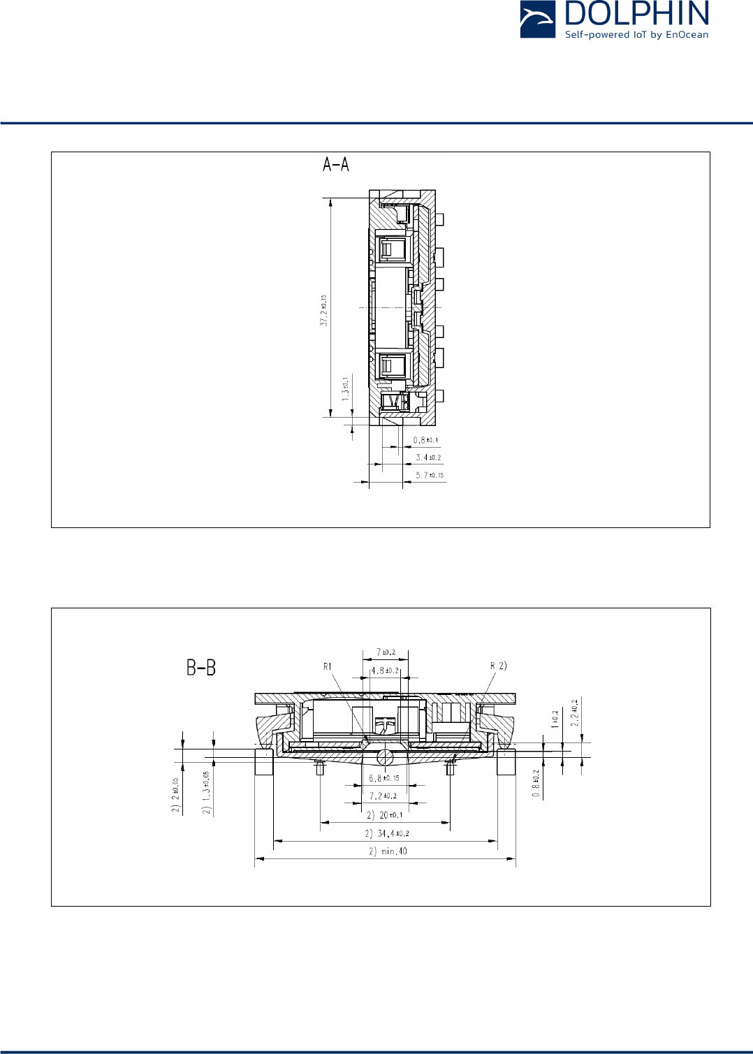
Figure 23 – PTM 215B, cut A
2) dimensions of rocker part
Figure 24 – PTM 215B, cut B and C
USER MANUAL
PTM 215B – 2.4 GHZ Pusbutton Transmitter Module
© 2016 EnOcean | www.enocean.com F-710-017, V1.0 PTM 215B User Manual | v0.8 | September 2016 | Page 36/42
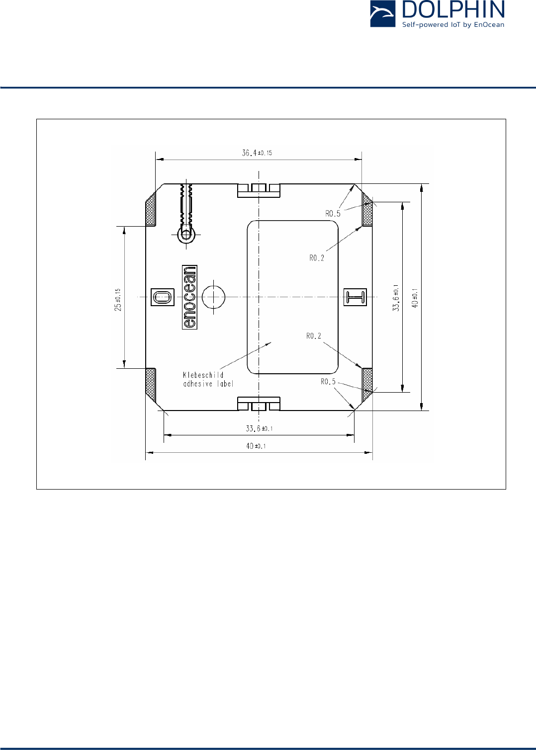
Hatched areas: support planes
Figure 25 – PTM 215B rear view
USER MANUAL
PTM 215B – 2.4 GHZ Pusbutton Transmitter Module
© 2016 EnOcean | www.enocean.com F-710-017, V1.0 PTM 215B User Manual | v0.8 | September 2016 | Page 37/42
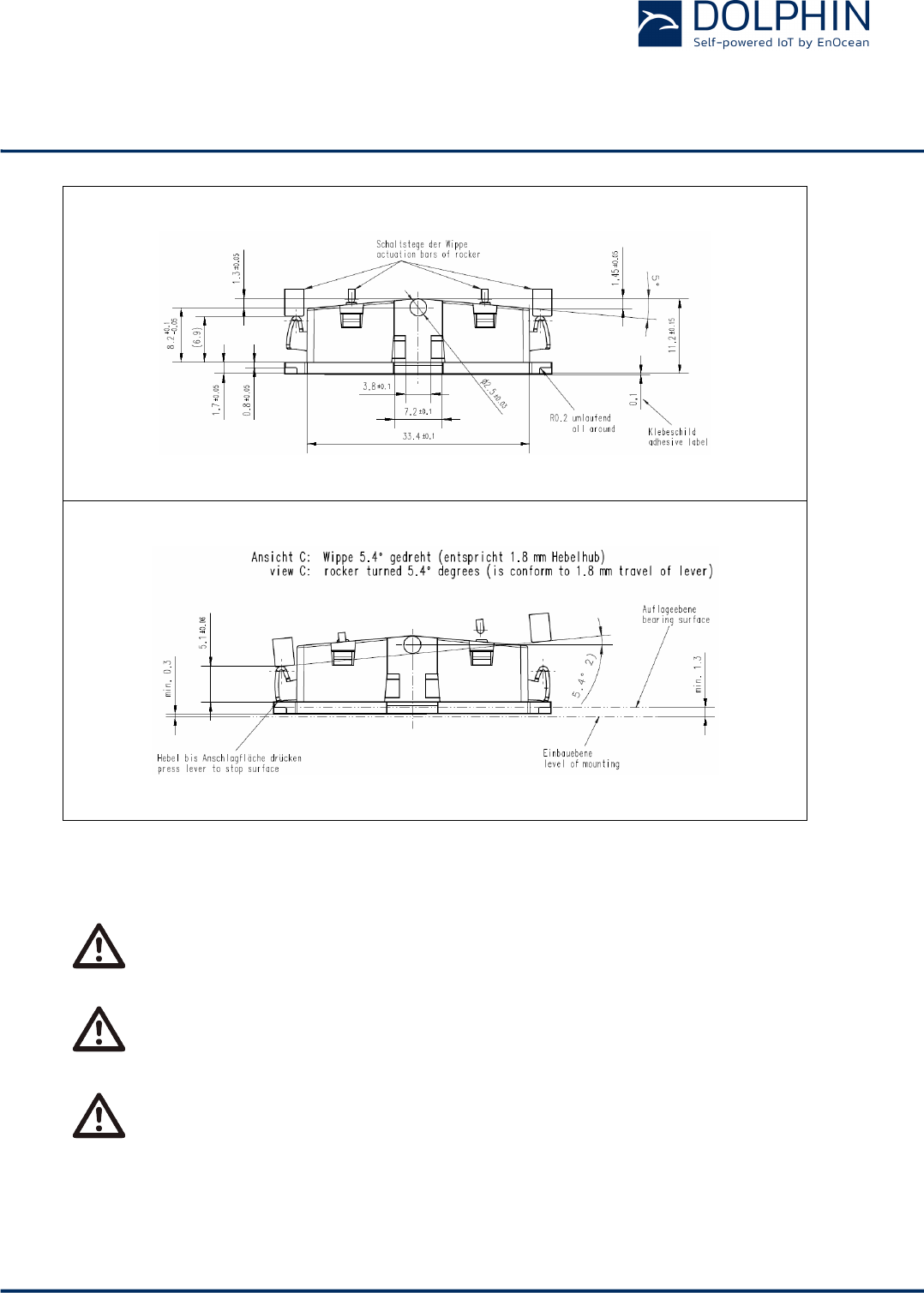
2) dimensions of rocker part
Figure 26 – PTM 215B, side view
If the rocker is not mounted on the rotation axis of PTM 215B several tolerances
have to be considered! The measure from support plane to top of the energy bow
is 7.70 mm +/- 0.3 mm!
The movement of the energy bow must not be limited by mounted rockers!
Catwalks of the switch rocker must not exert continuous forces on the button con-
tacts!
USER MANUAL
PTM 215B – 2.4 GHZ Pusbutton Transmitter Module
© 2016 EnOcean | www.enocean.com F-710-017, V1.0 PTM 215B User Manual | v0.8 | September 2016 | Page 38/42
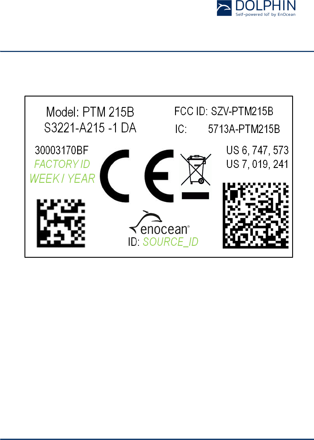
3.3 Device Label
Each PTM 215ZE module contains a device label as shown in Figure 27 below.
Figure 27 – PTM 215B device label
This device label identifies the following parameters in writing:
n Manufacturing date (WEEK / YEAR)
n Source Address (SOURCE_ID)
Note that the device label also contains a DMC code in the lower right corner as described
below.

USER MANUAL
PTM 215B – 2.4 GHZ Pusbutton Transmitter Module
© 2016 EnOcean | www.enocean.com F-710-017, V1.0 PTM 215B User Manual | v0.8 | September 2016 | Page 39/42
3.3.1 Device DMC
Each PTM 215B module contains a data matrix code (DMC) on the lower right hand side of
the device label which can be used to automatically scan device parameters.
The DMC uses the ECC200 standard to encode up to 52 characters. The content of the DMC
uses the following format:
<PRODUCT_NAME>ID<SOURCE_ID>OOB<DEVICE_KEY>
This identifies the following parameters:
n Product name
n 32 Bit Source Address (different for each device, excludes “E215” Prefix)
n 128 Bit device-unique random security key (different for each device)
One possible DMC reading could for instance be:
PTM215BID01500100OOB0123456789ABCDEF0123456789ABCDEF
This would identify the following parameters:
n Product name = PTM 215B
n Source Address = E21501500100
n Device-unique random security key = 0123456789ABCDEF0123456789ABCDEF

USER MANUAL
PTM 215B – 2.4 GHZ Pusbutton Transmitter Module
© 2016 EnOcean | www.enocean.com F-710-017, V1.0 PTM 215B User Manual | v0.8 | September 2016 | Page 40/42
4 APPLICATION INFORMATION
4.1 Transmission range
The main factors that influence the system transmission range are:
- Type and location of the antennas of receiver and transmitter
- Type of terrain and degree of obstruction of the link path
- Sources of interference affecting the receiver
- “Dead spots” caused by signal reflections from nearby conductive objects.
Since the expected transmission range strongly depends on this system conditions, range
tests should always be performed to determine the reliably achievable range under the giv-
en conditions.
The following figures should be treated as a rough guide only:
- Line-of-sight connections
Typically 10 m range in corridors, up to 30 m in halls
- Plasterboard walls / dry wood
Typically 10 m range, through max. 2 walls
- Ferro concrete walls / ceilings
Typically 5 m range, through max. 1 ceiling (depending on thickness)
- Fire-safety walls, elevator shafts, staircases and similar areas should be considered
as shielded
The angle at which the transmitted signal hits the wall is very important. The effective wall
thickness – and with it the signal attenuation – varies according to this angle. Signals
should be transmitted as directly as possible through the wall. Wall niches should be avoid-
ed.
Other factors restricting transmission range include:
- Switch mounting on metal surfaces (up to 30% loss of transmission range)
- Hollow lightweight walls filled with insulating wool on metal foil
- False ceilings with panels of metal or carbon fibre
- Lead glass or glass with metal coating, steel furniture
The distance between the receiver and other transmitting devices such as computers, audio
and video equipment that also emit high-frequency signals should be at least 0.5 m.

USER MANUAL
PTM 215B – 2.4 GHZ Pusbutton Transmitter Module
© 2016 EnOcean | www.enocean.com F-710-017, V1.0 PTM 215B User Manual | v0.8 | September 2016 | Page 41/42
5 REGULATORY INFORMATION
PTM 215B has been certified according to FCC, IC and CE regulations.
Changes or modifications not expressly approved by EnOcean could void the user's authori-
ty to operate the equipment.
5.1 FCC (United States) Certificate
<To be inserted>
5.1.1 FCC (United States) Regulatory Statement
This device complies with part 15 of the FCC Rules. Operation is subject to the following
two conditions:
(1) this device may not cause harmful interference, and
(2) this device must accept any interference received, including interference that may
cause undesired operation.

USER MANUAL
PTM 215B – 2.4 GHZ Pusbutton Transmitter Module
© 2016 EnOcean | www.enocean.com F-710-017, V1.0 PTM 215B User Manual | v0.8 | September 2016 | Page 42/42
5.2 IC (Industry Canada) Certificate
<To be inserted>
5.2.1 IC (Industry Canada) Regulatory Statement
This device complies with Industry Canada licence-exempt RSS standard(s).
Operation is subject to the following two conditions:
(1) this device may not cause interference, and
(2) this device must accept any interference, including interference that may cause unde-
sired operation of the device.
Le présent appareil est conforme aux CNR d'Industrie Canada applicables aux appareils
radio exempts de licence.
L'exploitation est autorisée aux deux conditions suivantes :
(1) l'appareil ne doit pas produire de brouillage, et
(2) l'utilisateur de l'appareil doit accepter tout brouillage radioélectrique subi, même si le
brouillage est susceptible d'en compromettre le fonctionnement.”