EnOcean PTM215Z 2.405GHz - 2.475GHz transmitter User Manual usersmanual
EnOcean GmbH 2.405GHz - 2.475GHz transmitter usersmanual
EnOcean >
Contents
- 1. usersmanual
- 2. User Manual
usersmanual

USER MANUAL V1.0
EnOcean GmbH
Kolpingring 18a
82041 Oberhaching
Germany
Phone +49.89.67 34 689-0
Fax +49.89.67 34 689-50
info@enocean.com
www.enocean.com
Subject to modifications
PTM 215Z User Manual | v1.0 | July 2013
Page 1/17
Patent protected:
US 6,747,573
US 7,019,241
Further patents pending
Pushbutton Transmitter Device
PTM 215Z
September 17, 2013

USER MANUAL V1.0
EnOcean GmbH
Kolpingring 18a
82041 Oberhaching
Germany
Phone +49.89.67 34 689-0
Fax +49.89.67 34 689-50
info@enocean.com
www.enocean.com
Subject to modifications
PTM 215Z User Manual | v1.4 | July 2013
Page 2/17
PTM 215Z
REVISION HISTORY
The following major modifications and improvements have been made to the first version of
this document:
No
Major Changes
1.0
Initial Release
Published by EnOcean GmbH, Kolpingring 18a, 82041 Oberhaching, Germany
www.enocean.com, info@enocean.com, phone ++49 (89) 6734 6890
© EnOcean GmbH
All Rights Reserved
Important!
This information describes the type of component and shall not be considered as assured
characteristics. No responsibility is assumed for possible omissions or inaccuracies. Circuitry
and specifications are subject to change without notice. For the latest product specifica-
tions, refer to the EnOcean website: http://www.enocean.com.
As far as patents or other rights of third parties are concerned, liability is only assumed for
devices, not for the described applications, processes and circuits.
EnOcean does not assume responsibility for use of devices described and limits its liability
to the replacement of devices determined to be defective due to workmanship. Devices or
systems containing RF components must meet the essential requirements of the local legal
authorities.
The devices must not be used in any relation with equipment that supports, directly or indi-
rectly, human health or life or with applications that can result in danger for people, ani-
mals or real value.
Components of the devices are considered and should be disposed of as hazardous waste.
Local government regulations are to be observed.
Packing: Please use the recycling operators known to you. By agreement we will take pack-
ing material back if it is sorted. You must bear the costs of transport. For packing material
that is returned to us unsorted or that we are not obliged to accept, we shall have to in-
voice you for any costs incurred.

USER MANUAL V1.0
EnOcean GmbH
Kolpingring 18a
82041 Oberhaching
Germany
Phone +49.89.67 34 689-0
Fax +49.89.67 34 689-50
info@enocean.com
www.enocean.com
Subject to modifications
PTM 215Z User Manual | v1.4 | July 2013
Page 3/17
PTM 215Z
TABLE OF CONTENT
1 GENERAL DESCRIPTION .................................................................................... 4
1.1 Basic Functionality ........................................................................................... 4
1.2 Typical Applications .......................................................................................... 5
1.3 Technical Data ................................................................................................. 5
1.4 Mechanical Interface ......................................................................................... 5
1.5 Environmental Conditions ................................................................................ 10
1.6 Ordering Information ...................................................................................... 10
2 FUNCTIONAL DESCRIPTION ............................................................................. 11
2.1 Block Diagram ............................................................................................... 11
2.2 Contact Nipples Designation ............................................................................ 12
2.3 Operating modes ........................................................................................... 12
2.3.1 Normal Mode .............................................................................................. 13
2.3.1.1 Security Parameters ................................................................................. 13
2.3.2 Commissioning Mode ................................................................................... 14
2.3.2.1 Radio Channel Selection ............................................................................ 14
2.3.2.2 Join Request ............................................................................................ 14
2.4 Construction of application specific Switch Rockers ............................................. 15
2.5 Device Mounting ............................................................................................ 15
2.6 Regulatory Notes ........................................................................................... 16
2.6.1 FCC Regulatory Statement ........................................................................... 16
3 Transmission Range ....................................................................................... 17
USER MANUAL V1.0
EnOcean GmbH
Kolpingring 18a
82041 Oberhaching
Germany
Phone +49.89.67 34 689-0
Fax +49.89.67 34 689-50
info@enocean.com
www.enocean.com
Subject to modifications
PTM 215Z User Manual | v1.4 | July 2013
Page 4/17
PTM 215Z
1 GENERAL DESCRIPTION
The radio transmitter device PTM 215Z from EnOcean enables the implementation of wire-
less remote controls without batteries.
Power is provided by a built-in electro-dynamic power generator. The PTM 215Z device
transmits data based on the 2.4GHz ZigBee Green Power standard.
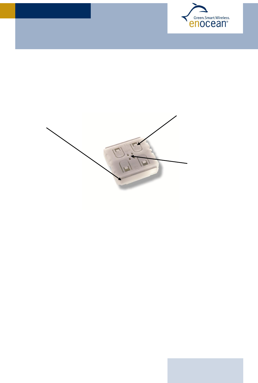
The outer appearance of PTM 215Z is shown on the picture below.
Electro-dynamic powered radio transmitter device PTM 215Z
1.1 Basic Functionality
PTM 215Z devices contain an electro-dynamic energy transducer which is actuated by a
bow (1). This bow is pushed by an appropriate push button, switch rocker or a similar con-
struction mounted onto the device. An internal spring will release the energy bow as soon
as it is not pushed down anymore.
When the energy bow is pushed down, electrical energy is created and a ZigBee Green
Power radio telegram is transmitted. Releasing the energy bow similarly generates energy
which is used to transmit a different ZigBee Green Power radio telegram.
It is therefore possible to distinguish between radio telegrams sent when the energy bar
was pushed and radio telegrams sent when the energy bar was released.
By identifying these different telegrams types and measuring the time between pushing
and releasing of the energy bar, it is possible to distinguish between “Long” and “Short”
push button presses. This enables simple implementation of applications such as dimming
control or blinds control including slat action.
(2) Contact nipples
for switch rocker
identification
(1) Energy bow
on both device sides
Rotation axis for
pushbuttons or
switch rocker

USER MANUAL V1.0
EnOcean GmbH
Kolpingring 18a
82041 Oberhaching
Germany
Phone +49.89.67 34 689-0
Fax +49.89.67 34 689-50
info@enocean.com
www.enocean.com
Subject to modifications
PTM 215Z User Manual | v1.4 | July 2013
Page 5/17
PTM 215Z
The PTM 215Z radio telegram identifies the status (pressed or not pressed) of the four con-
tact nipples (2) when the energy bow was pushed or released. This enables the implemen-
tation of up to two switch rockers or up to four pushbuttons.
1.2 Typical Applications
Typical applications are found in the following areas:
Building installation
Consumer electronics
Light and door switches
Key products include wall-mounted switches and handheld remote controls supporting up to
two rockers or up to four pushbuttons.
PTM 215Z pushbutton transmitters are self-powered (no batteries) and therefore mainte-
nance-free. They can be used in hermetically sealed systems or in remote (not easily ac-
cessible) locations.
1.3 Technical Data
Power supply Internal electro-dynamic power generator actuated by the energy bow
Antenna Internal PCB antenna
Frequency 2.4GHz / IEEE 802.15.4 channels 11, 15, 20 or 25
(User selectable during commissioning)
Data rate 250 kbps (according to IEEE 802.15.4 standard)
Conducted output power typ. 0dBm
Button inputs Up to four buttons
ZigBee Device ID 0x02 (ZigBee on / off switch)
Security mode Unique device security key
Transmission range typ. 175 m free field / 20 m indoor
Device identifier Individual 32-bit ZGPD SrcId (factory programmed)
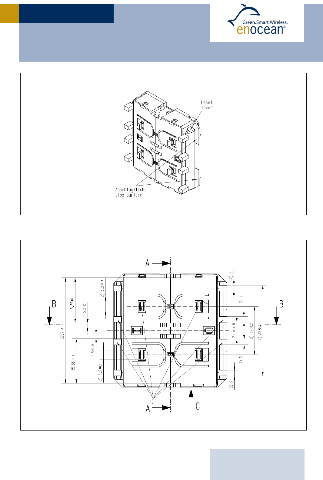
1.4 Mechanical Interface
Device dimensions (inclusive rotation axis and energy bow) 40.0 x 40.0 x 11.2 mm
Device weight 20 g ± 1 g
Energy bow travel / operating force 1.8 mm / typ. 8 N
At room temperature
Only one of the two energy bows may be actuated at the same time!
Restoring force at energy bow typ. 0.7 N to 4 N
Minimum restoring force of 0.5 N is required for correct operation
Number of operations at 25°C typ. 100.000 actuations tested according to VDE 0632 / EN 60669
Cover material Hostaform (POM)
Energy bow material PBT (50% GV)
USER MANUAL V1.0
EnOcean GmbH
Kolpingring 18a
82041 Oberhaching
Germany
Phone +49.89.67 34 689-0
Fax +49.89.67 34 689-50
info@enocean.com
www.enocean.com
Subject to modifications
PTM 215Z User Manual | v1.4 | July 2013
Page 6/17
PTM 215Z
PTM 215Z without antenna, tilted view (including rocker catwalks)
1) these catwalks are not needed when using one single rocker only 2) dimensions of rocker part
PTM 215Z, top view (note cut A, B and C marking)
USER MANUAL V1.0
EnOcean GmbH
Kolpingring 18a
82041 Oberhaching
Germany
Phone +49.89.67 34 689-0
Fax +49.89.67 34 689-50
info@enocean.com
www.enocean.com
Subject to modifications
PTM 215Z User Manual | v1.4 | July 2013
Page 7/17
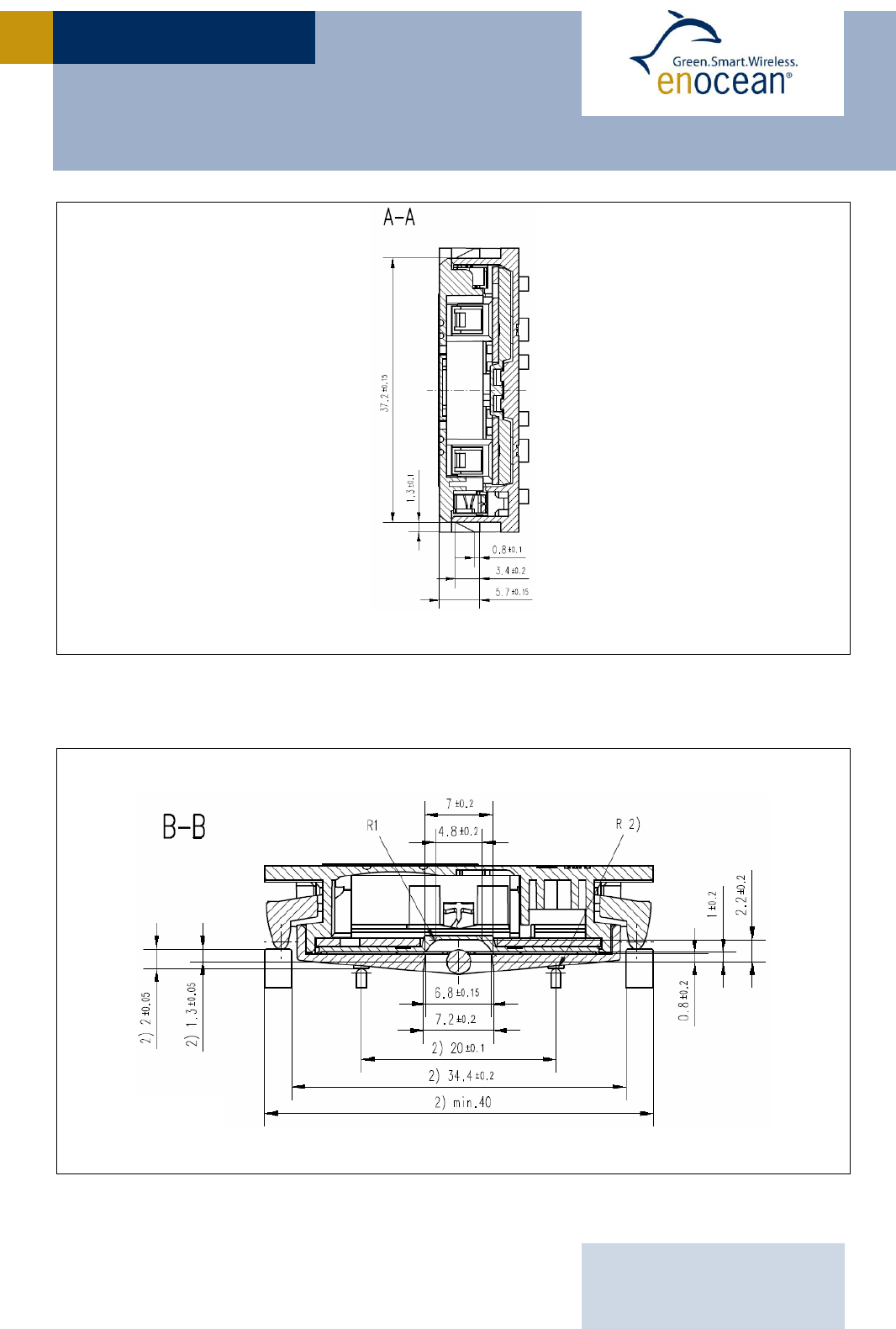
PTM 215Z
PTM 215Z, cut A
2) dimensions of rocker part
PTM 215Z, cut B and C
USER MANUAL V1.0
EnOcean GmbH
Kolpingring 18a
82041 Oberhaching
Germany
Phone +49.89.67 34 689-0
Fax +49.89.67 34 689-50
info@enocean.com
www.enocean.com
Subject to modifications
PTM 215Z User Manual | v1.4 | July 2013
Page 8/17
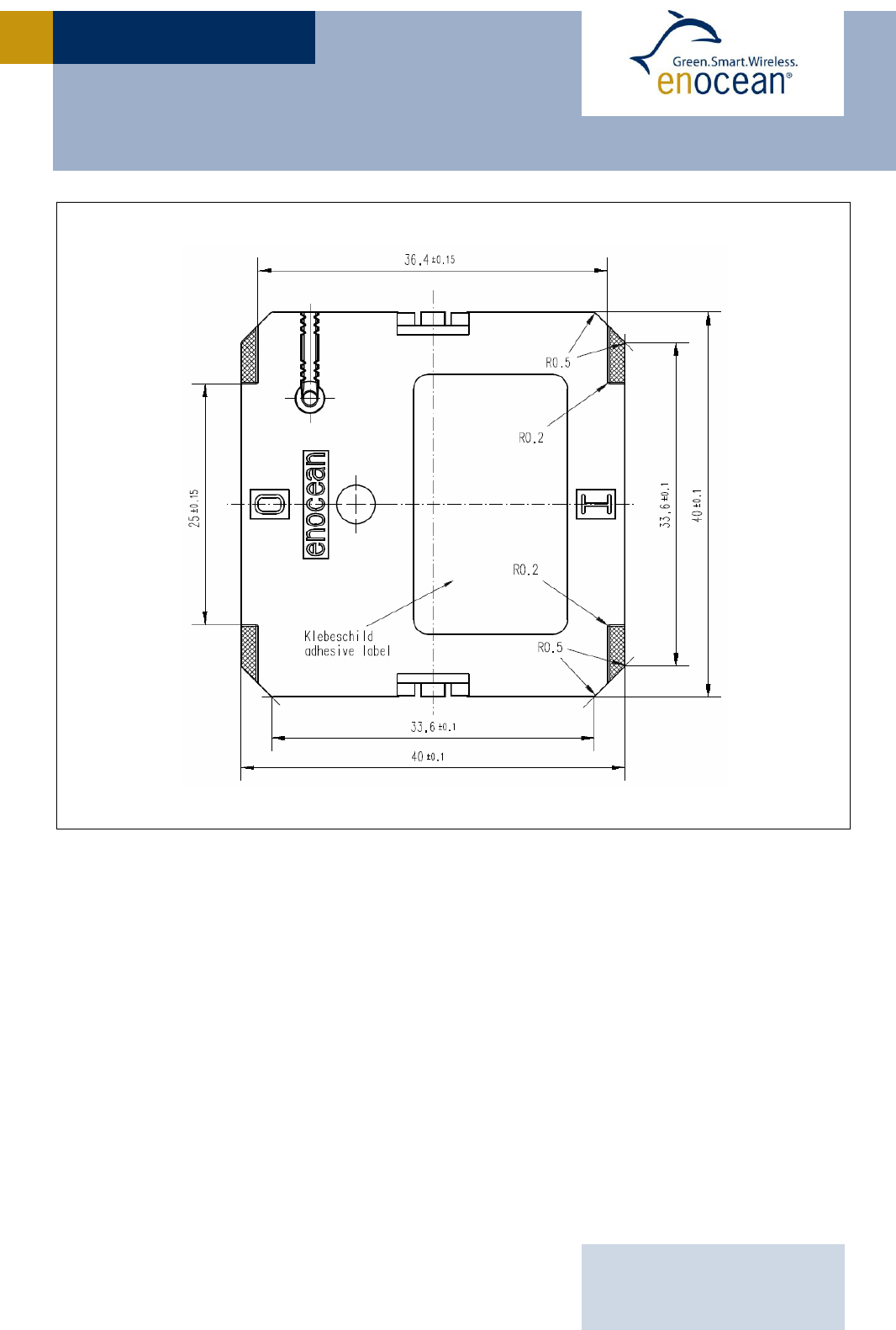
PTM 215Z
Hatched areas: support planes
PTM 215Z rear view
USER MANUAL V1.0
EnOcean GmbH
Kolpingring 18a
82041 Oberhaching
Germany
Phone +49.89.67 34 689-0
Fax +49.89.67 34 689-50
info@enocean.com
www.enocean.com
Subject to modifications
PTM 215Z User Manual | v1.4 | July 2013
Page 9/17
PTM 215Z
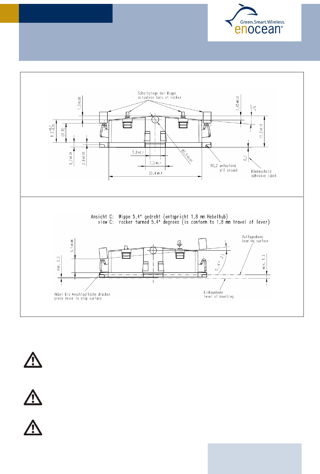
2) dimensions of rocker part
PTM 215Z, side view
If the rocker is not mounted on the rotation axis of PTM 215Z several tolerances
have to be considered! The measure from support plane to top of the energy bow
is 7.70 mm +/- 0.3 mm!
The movement of the energy bow must not be limited by mounted rockers!
Catwalks of the switch rocker must not exert continuous forces on contact nipples!

USER MANUAL V1.0
EnOcean GmbH
Kolpingring 18a
82041 Oberhaching
Germany
Phone +49.89.67 34 689-0
Fax +49.89.67 34 689-50
info@enocean.com
www.enocean.com
Subject to modifications
PTM 215Z User Manual | v1.4 | July 2013
Page 10/17
PTM 215Z
1.5 Environmental Conditions
Operating temperature -5 °C up to +45 °C
Storage temperature -25 °C up to +65 °C
Humidity 0% to 95% r.h., non-condensing
1.6 Ordering Information
Type
Ordering Code
PTM 215Z
S3071-A215
USER MANUAL V1.0
EnOcean GmbH
Kolpingring 18a
82041 Oberhaching
Germany
Phone +49.89.67 34 689-0
Fax +49.89.67 34 689-50
info@enocean.com
www.enocean.com
Subject to modifications
PTM 215Z User Manual | v1.4 | July 2013
Page 11/17
PTM 215Z
2 FUNCTIONAL DESCRIPTION
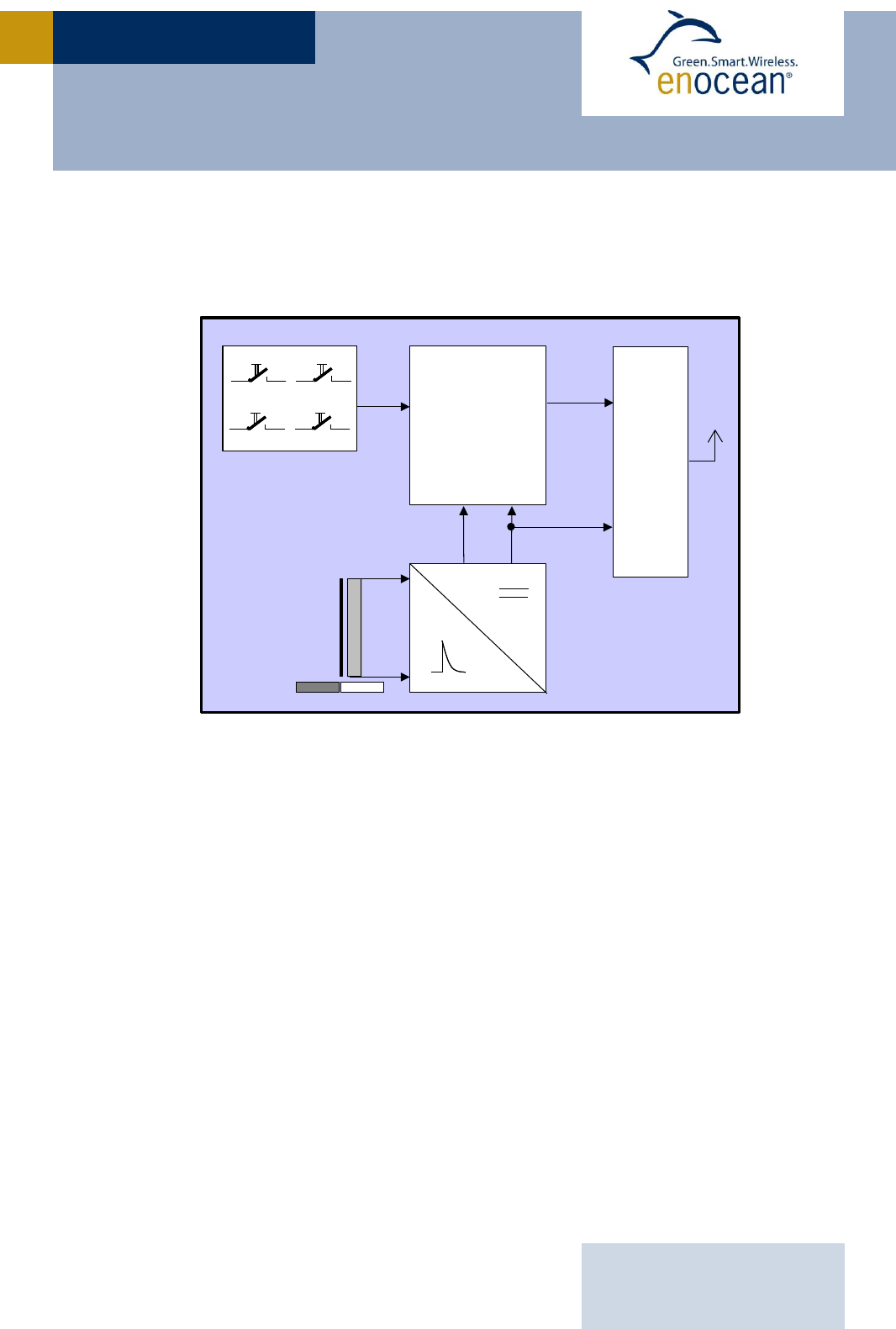
2.1 Block Diagram
Block diagram of PTM 215Z
Energy Bow / Power Generator
Converts the motion of the energy bow into electrical energy.
Power Converter
Converts the energy of the power generator into a stable DC supply voltage for the device
electronics.
Processor
Determines the status of the contact nipples and the energy bow, encodes this status into a
data word, generates the proper radio telegram structure and sends it to the radio
transmitter.
Radio transmitter
Transmits the data in the form of a series of short ZigBee Green Power radio telegrams.
Processor
HF
Contact Nipples
Energy
Bow
Power
Converter
Data
DC Power
Pushed/Released
Ant
NS
Processor
HF
Contact Nipples
Energy
Bow
Power
Converter
Data
DC Power
Pushed/Released
Ant
NS
NS
Status
USER MANUAL V1.0
EnOcean GmbH
Kolpingring 18a
82041 Oberhaching
Germany
Phone +49.89.67 34 689-0
Fax +49.89.67 34 689-50
info@enocean.com
www.enocean.com
Subject to modifications
PTM 215Z User Manual | v1.4 | July 2013
Page 12/17
PTM 215Z
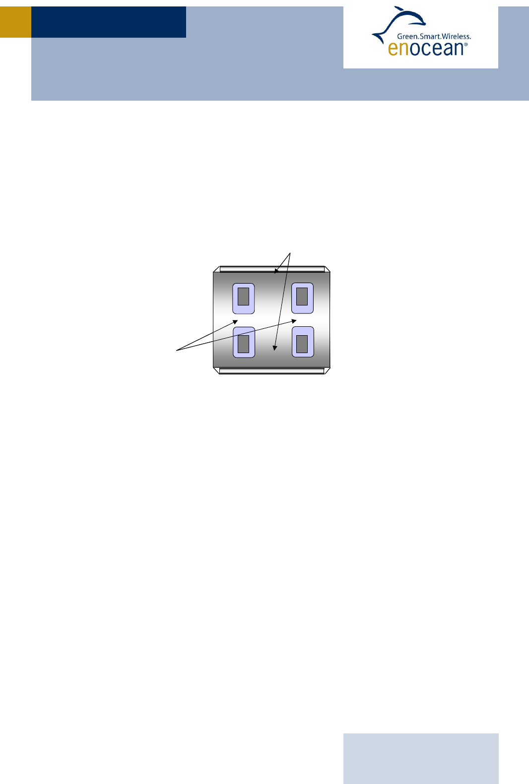
2.2 Contact Nipples Designation
PTM 215Z devices provide four contact nipples. They are grouped into two channels (Chan-
nel A and Channel B) each containing two contact nipples (State O and State I).
The state of all four contact nipples (pressed or not pressed) is transmitted together with a
unique device identification (fixed 32-bit ZGPD SrcId) whenever the energy bow is pushed
or released.
The picture below shows the arrangement of the four nipples and their designation:
Contact nipple designation
2.3 Operating modes
PTM 215Z supports two operating modes:
Normal mode
In this mode, data telegrams are sent according to the button(s) pressed
Commissioning mode
In this mode, the Radio channel is changed according to the button pressed and a
“Join” telegram is transmitted
These two modes are outlined in more detail in the following chapters.
O
I
BA
CHANNEL
STATE
O
I
BA
CHANNEL
STATE

USER MANUAL V1.0
EnOcean GmbH
Kolpingring 18a
82041 Oberhaching
Germany
Phone +49.89.67 34 689-0
Fax +49.89.67 34 689-50
info@enocean.com
www.enocean.com
Subject to modifications
PTM 215Z User Manual | v1.4 | July 2013
Page 13/17
PTM 215Z
2.3.1 Normal Mode
In normal mode, PTM 215Z transmits secure data telegrams reflecting the state of the four
device buttons whenever the energy bar is pressed or released. The state of the four but-
tons is encoded in one data byte of payload.
The data telegrams sent when the energy bar is pressed are different from the ones sent
when the energy bar is released.
In the current implementation, the following correspondence between energy bar state,
contact nipple state and data payload is implemented:
- Energy bar pressed
- No contact nipple (energy bar only) or contact nipple B0: 0x22
- Contact nipple A0: 0x10
- Contact nipple A1: 0x11
- Contact nipple B1: 0x12
- Contact nipples A1 and B1: 0x62
- Contact nipples A0 and B0: 0x64
- All other contact nipple states: No action
- Energy bar released
- Contact nipples A1 and B1: 0x63
- Contact nipples A0 and B0: 0x65
- All other contact nipple states: No action
2.3.1.1 Security Parameters
PTM 215Z transmits data in secured format in accordance with the ZigBee Green Power
Specification Revision 23, Version 1.0 using the following security parameters:
- zgpSecurityLevel is 0b10
Full 4Byte frame counter and full 4Byte MIC
- zgpSecurityKeyType is 0b100
Out of the box ZGPD Key
Each PTM 215Z device contains its own unique and random security key. This key will be
transmitted to the host system in the “Join” request as outlined in the following chapter.

USER MANUAL V1.0
EnOcean GmbH
Kolpingring 18a
82041 Oberhaching
Germany
Phone +49.89.67 34 689-0
Fax +49.89.67 34 689-50
info@enocean.com
www.enocean.com
Subject to modifications
PTM 215Z User Manual | v1.4 | July 2013
Page 14/17
PTM 215Z
2.3.2 Commissioning Mode
In order to join an existing ZigBee Green Power compliant network, PTM 215Z devices need
to be configured for the correct radio channel and subsequently issue a properly formatted
“Join” request outlining its device and security parameters.
The combination of these tasks is referred to as commissioning.
2.3.2.1 Radio Channel Selection
PTM 215Z devices support up to four pre-configured, dynamically selectable radio channels.
In the current implementation, radio channels 11, 15, 20 and 25 according to the IEEE
802.15.4 standard are supported.
The proper radio channel is selected by pressing one of the four contact nipples together
with the energy bow and holding it for a period longer than 7 seconds. If such long press is
detected then PTM 215Z will set the radio channel according to the button pressed.
In the current implementation, the correspondence between contact nipple pressed and
radio channel selected is as follows:
- B0: Channel 11
- A0: Channel 15
- A1: Channel 20
- B1: Channel 25
PTM 215Z will issue a “Join” telegram on the selected radio channel as soon as the energy
bow is released.
2.3.2.2 Join Request
Whenever a radio channel is selected in accordance to 2.3.2.1, PTM 215Z devices will issue
a “Join” request. This Join request will be sent as broadcast (destination ID 0xFFFF) on the
selected channel.
The “Join” request will identify the PTM 215Z device as ZigBee on / off switch (device ID
0x02) and contain the unique ZGPD SrcId as well as the unique device security key encod-
ed with the ZigBee Trust Center Link Key.
USER MANUAL V1.0
EnOcean GmbH
Kolpingring 18a
82041 Oberhaching
Germany
Phone +49.89.67 34 689-0
Fax +49.89.67 34 689-50
info@enocean.com
www.enocean.com
Subject to modifications
PTM 215Z User Manual | v1.4 | July 2013
Page 15/17
PTM 215Z
2.4 Construction of application specific Switch Rockers
For CAD system development support, 3D construction data is available from EnOcean (IGS
data). Using this data, the mechanical interface is fixed, and the shape and surface of the
rocker(s) can be changed according to requirements.
Polycarbonate is recommended as rocker material since it is both buckling resistant and
wear-proof. It is also recommended to apply Teflon varnish in the areas of actuation.
It is recommended using non-conductive material for the rockers to ensure best
transmission range. Avoid if possible metallic materials or plastics with conducting
ingredients such as graphite.
2.5 Device Mounting
For mounting the PTM 21x device into an application specific case, the package outline
drawings of the device are given in chapter 1.4.
More detailed 3D construction data is available from EnOcean in IGS format.
It is recommended not to mount the device directly onto metal surfaces or into
metal frames since this can lead to significant loss of transmission range.

USER MANUAL V1.0
EnOcean GmbH
Kolpingring 18a
82041 Oberhaching
Germany
Phone +49.89.67 34 689-0
Fax +49.89.67 34 689-50
info@enocean.com
www.enocean.com
Subject to modifications
PTM 215Z User Manual | v1.4 | July 2013
Page 16/17
PTM 215Z
2.6 Regulatory Notes
PTM 215Z has been certified according to applicable regulations.
Changes or modifications not expressly approved by EnOcean could void the user's authori-
ty to operate the equipment.
2.6.1 FCC (United States) Regulatory Statement
This device complies with part 15 of the FCC Rules. Operation is subject to the following
two conditions:
(1) this device may not cause harmful interference, and
(2) this device must accept any interference received, including interference that may
cause undesired operation.
2.6.2 IC (Industry Canada) Regulatory Statement
This device complies with Industry Canada licence-exempt RSS standard(s).
Operation is subject to the following two conditions:
(1) this device may not cause interference, and
(2) this device must accept any interference, including interference that may cause unde-
sired operation of the device.
Le présent appareil est conforme aux CNR d'Industrie Canada applicables aux appareils
radio exempts de licence.
L'exploitation est autorisée aux deux conditions suivantes :
(1) l'appareil ne doit pas produire de brouillage, et
(2) l'utilisateur de l'appareil doit accepter tout brouillage radioélectrique subi, même si le
brouillage est susceptible d'en compromettre le fonctionnement.”

USER MANUAL V1.0
EnOcean GmbH
Kolpingring 18a
82041 Oberhaching
Germany
Phone +49.89.67 34 689-0
Fax +49.89.67 34 689-50
info@enocean.com
www.enocean.com
Subject to modifications
PTM 215Z User Manual | v1.4 | July 2013
Page 17/17
PTM 215Z
3 Transmission Range
The main factors that influence the system transmission range are:
- Type and location of the antennas of receiver and transmitter
- Type of terrain and degree of obstruction of the link path
- Sources of interference affecting the receiver
- “Dead spots” caused by signal reflections from nearby conductive objects.
Since the expected transmission range strongly depends on this system conditions, range
tests should always be performed to determine the reliably achievable range under the
given conditions.
The following figures should be treated as a rough guide only:
- Line-of-sight connections
Typically 20 m range in corridors, up to 75 m in halls
- Plasterboard walls / dry wood
Typically 20 m range, through max. 3 walls
- Ferro concrete walls / ceilings
Typically 7 m range, through max. 1 ceiling
- Fire-safety walls, elevator shafts, staircases and similar areas should be considered
as shielded
The angle at which the transmitted signal hits the wall is very important. The effective wall
thickness – and with it the signal attenuation – varies according to this angle. Signals
should be transmitted as directly as possible through the wall. Wall niches should be
avoided.
Other factors restricting transmission range include:
- Switch mounting on metal surfaces (up to 30% loss of transmission range)
- Hollow lightweight walls filled with insulating wool on metal foil
- False ceilings with panels of metal or carbon fibre
- Lead glass or glass with metal coating, steel furniture
The distance between the receiver and other transmitting devices such as computers, audio
and video equipment that also emit high-frequency signals should be at least 0.5 m.