User Manual

USER MANUAL V0.6
EnOcean GmbH
Kolpingring 18a
82041 Oberhaching
Germany
Phone +49.89.67 34 689-0
Fax +49.89.67 34 689-50
info@enocean.com
www.enocean.com
Subject to modifications
PTM 335 / 335C User Manual V0.6
October 6, 2011 1:33 PM
Page 1/11
Patent protected:
WO98/36395, DE 100 25 561, DE 101 50 128,
WO 2004/051591, DE 103 01 678 A1, DE 10309334,
WO 04/109236, WO 05/096482, WO 02/095707,
US 6,747,573, US 7,019,241
Observe precautions! Electrostatic sensitive devices!
Transmitter Module
PTM 335 / 335C
October 6, 2011

USER MANUAL V0.6
© 2011 EnOcean | www.enocean.com PTM 335 / 335C User Manual 0.7 | Page 2/11
PTM 335 / 335C
REVISION HISTORY
The following major modifications and improvements have been made to the first version
of this document:
No
Major Changes
0.5
Initial version
0.6
Updated version, delivered with B-samples
0.7
Output power data 868 MHz updated
Published by EnOcean GmbH, Kolpingring 18a, 82041 Oberhaching, Germany
www.enocean.com, info@enocean.com, phone ++49 (89) 6734 6890
© EnOcean GmbH
All Rights Reserved
Important!
This information describes the type of component and shall not be considered as assured
characteristics. No responsibility is assumed for possible omissions or inaccuracies. Cir-
cuitry and specifications are subject to change without notice. For the latest product speci-
fications, refer to the EnOcean website: http://www.enocean.com.
As far as patents or other rights of third parties are concerned, liability is only assumed for
modules, not for the described applications, processes and circuits.
EnOcean does not assume responsibility for use of modules described and limits its liability
to the replacement of modules determined to be defective due to workmanship. Devices or
systems containing RF components must meet the essential requirements of the local legal
authorities.
The modules must not be used in any relation with equipment that supports, directly or
indirectly, human health or life or with applications that can result in danger for people,
animals or real value.
Components of the modules are considered and should be disposed of as hazardous waste.
Local government regulations are to be observed.
Packing: Please use the recycling operators known to you.

USER MANUAL V0.6
© 2011 EnOcean | www.enocean.com PTM 335 / 335C User Manual 0.7 | Page 3/11
PTM 335 / 335C
TABLE OF CONTENT
1 GENERAL DESCRIPTION ................................................................................. 4
1.1 Basic Functionality ......................................................................................... 4
1.2 Technical Data .............................................................................................. 4
1.3 Physical Dimensions....................................................................................... 4
1.4 Environmental Conditions ............................................................................... 6
1.5 Ordering Information ..................................................................................... 6
2 FUNCTIONAL DESCRIPTION ............................................................................ 6
2.1 Block diagram ............................................................................................... 6
2.2 Pin out and pin description ............................................................................. 6
2.3 Absolute maximum ratings (non operating) ...................................................... 7
2.4 Maximum Ratings (operating) ......................................................................... 7
2.5 Radio telegram .............................................................................................. 7
2.6 Transmit timing ............................................................................................. 7
3 APPLICATIONS INFORMATION ......................................................................... 8
3.1 Transmission range ....................................................................................... 8
4 AGENCY CERTIFICATIONS (after release for series production) ........................... 9
4.1 CE approval .................................................................................................. 9
4.2 FCC (United States) Certification ................................................................... 10
4.3 IC (Industry Canada) Certification ................................................................. 11
USER MANUAL V0.6
© 2011 EnOcean | www.enocean.com PTM 335 / 335C User Manual 0.7 | Page 4/11
PTM 335 / 335C
1 GENERAL DESCRIPTION
1.1 Basic Functionality
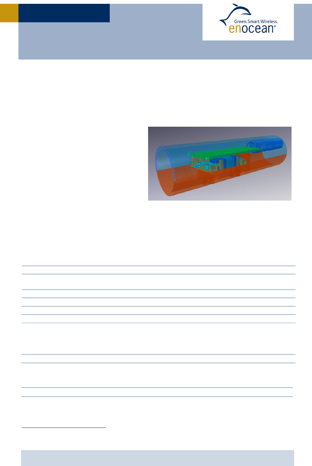
The radio transmitter module PTM 335 from EnOcean enables the implementation of wire-
less sensors door sensors without batteries.
Functional Principle
When an energy pulse is supplied by
ECO 200 an RF telegram is transmitted
including a unique 32-bit module ID,
and information if an open or close
event has happened. This information is
derived from the polarity of the energy
pulse.
PTM 335 is connected to ECO 200 via a
contact spring.
Product variants
PTM 335: 868 MHz variant
PTM 335C: 315 MHz variant
1.2 Technical Data
Power supply ECO 200
Antenna helical antenna
Frequency 315.0 MHz/868 MHz
Transmission power radiated 315 MHz: 90…95 dBµV/m 868 MHz: typ. 0 dBm EIRP
EnOcean Telegram type EEP F6-10-00
EMI resistance 3 V/m according to EN 61000-6-1
Transmission range up to 200 m free field, up to 30 m indoor
Largely depends on antenna design and integration into housing
Potential reduction of range when integrated in/adjacent
to metal doors or frames or other metal objects1
Approvals FCC/IC limited modular approval (315 MHz) / R&TTE (868 MHz)
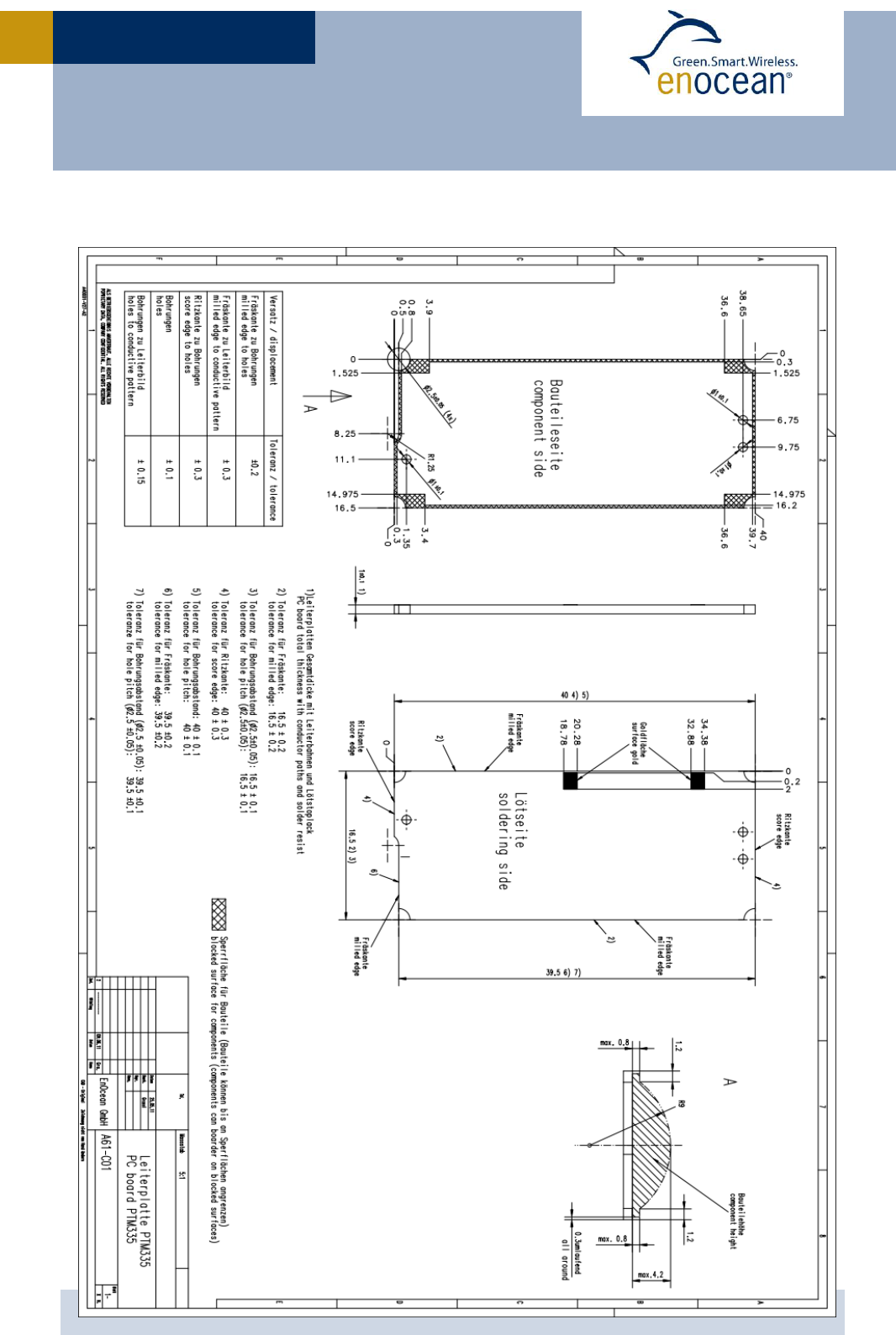
1.3 Physical Dimensions
1 Not suited for use within metal enclosures.
Module dimensions (excluding antenna) 16.5 x 40.0 x 3.0 mm
USER MANUAL V0.6
© 2011 EnOcean | www.enocean.com PTM 335 / 335C User Manual 0.7 | Page 5/11
PTM 335 / 335C

USER MANUAL V0.6
© 2011 EnOcean | www.enocean.com PTM 335 / 335C User Manual 0.7 | Page 6/11
PTM 335 / 335C
1.4 Environmental Conditions
Operating temperature -25 °C … +65 °C
Storage temperature -40 °C … +85 °C
Humidity 0% … 93% r.h., non-condensing
1.5 Ordering Information
Type
Ordering Code
Frequency
PTM 335
S3001-A335
868.3 MHz
PTM 335C
S3031-A335
315.0 MHz
2 FUNCTIONAL DESCRIPTION
2.1 Block diagram
At power-up by an energy pulse at AC1, AC2 a DC voltage is provided to the internal micro
controller. The microcontroller reads the polarity of the supply voltage pulse.
After that 3 identical radio telegrams containing polarity information and 32 bit module ID
are transmitted.
2.2 Pin out and pin description
Symbol
Function
Characteristics
AC1
Input for ECO 200
ECO 200 or
equivalent energy pulse
AC2
Input for ECO 200
ECO 200 or
equivalent energy pulse
RF_HELIX
RF output
Output for pre-installed
helical antenna

USER MANUAL V0.6
© 2011 EnOcean | www.enocean.com PTM 335 / 335C User Manual 0.7 | Page 7/11
PTM 335 / 335C
2.3 Absolute maximum ratings (non operating)
Symbol
Parameter
Min
Max
Units
AC1
AC2
Supply voltage
0
17
V
2.4 Maximum Ratings (operating)
Symbol
Parameter
Min
Max
Units
AC1
AC2
Supply voltage
0
15
V
2.5 Radio telegram
PTM 335 transmits a radio telegram according to EEP F6-10-00.
Status “open” is represented by 0xC0
(ECO 200 tension spring “up” = towards PCB)
Status “closed” is represented by 0xF0
(ECO 200 tension spring “down” = away from PCB)
http://www.enocean-alliance.org/fileadmin/redaktion/enocean_alliance/pdf/EnOcean_Equipment_Profiles_EEP2.1.pdf
2.6 Transmit timing
The setup of the transmission timing allows avoiding possible collisions with data packages
of other EnOcean transmitters as well as disturbances from the environment. With each
transmission cycle, 3 identical subtelegrams are transmitted within 40 ms. The transmis-
sion of a subtelegram lasts approximately 0.7 ms. The delay between the three transmis-
sion bursts is affected at random.

USER MANUAL V0.6
© 2011 EnOcean | www.enocean.com PTM 335 / 335C User Manual 0.7 | Page 8/11
PTM 335 / 335C
3 APPLICATIONS INFORMATION
3.1 Transmission range
The main factors that influence the system transmission range are type and location of the
antennas of the receiver and the transmitter, type of terrain and degree of obstruction of
the link path, sources of interference affecting the receiver, and “dead” spots caused by
signal reflections from nearby conductive objects. Since the expected transmission range
strongly depends on this system conditions, range tests should categorically be performed
before notification of a particular range that will be attainable by a certain application.
The following figures for expected transmission range are considered by using a PTM, a
STM or a TCM radio transmitter device and the TCM radio receiver device with preinstalled
whip antenna and may be used as a rough guide only:
Line-of-sight connections: Typically 30 m range in corridors, up to 100 m in halls
Plasterboard walls / dry wood: Typically 30 m range, through max. 5 walls
Ferroconcrete walls / ceilings: Typically 10 m range, through max. 1 ceiling
Fire-safety walls, elevator shafts, staircases and supply areas should be considered as
screening.
The angle at which the transmitted signal hits the wall is very important. The effective wall
thickness – and with it the signal attenuation – varies according to this angle. Signals
should be transmitted as directly as possible through the wall. Wall niches should be
avoided. Other factors restricting transmission range:
Switch mounted on metal surfaces (up to 30% loss of transmission range)
Hollow lightweight walls filled with insulating wool on metal foil
False ceilings with panels of metal or carbon fiber
Lead glass or glass with metal coating, steel furniture
The distance between EnOcean receivers and other transmitting devices such as comput-
ers, audio and video equipment that also emit high-frequency signals should be at least 0.5
m.
A summarized application note to determine the transmission range within buildings is
available as download from www.enocean.com.
PTM 335 / PTM 335C is optimized for use in wooden door frames.
(Performance was tested with wood adjacent to simulated plastic housing around PTM 335)
Radio performance may vary due to proximity of other material in installation (e.g. plastic).
Any metal parts close to PTM 335/PTM 335C will degrade performance or at least change
radiation pattern.

USER MANUAL V0.6
© 2011 EnOcean | www.enocean.com PTM 335 / 335C User Manual 0.7 | Page 9/11
PTM 335 / 335C
4 AGENCY CERTIFICATIONS (after release for series production)
The modules have been tested to fulfil the approval requirements for CE (PTM 335) and
FCC/IC (PTM 335C) based on the built-in firmware.
4.1 CE approval
The module bears the EC conformity marking CE and conforms to the R&TTE EU-directive
on radio equipment. The assembly conforms to the European and national requirements of
electromagnetic compatibility. The conformity has been proven and the according docu-
mentation has been deposited at EnOcean. The modules can be operated without notifica-
tion and free of charge in the area of the European Union, and in Switzerland. The following
provisos apply:
EnOcean RF modules must not be modified or used outside their specification
limits.
EnOcean RF modules may only be used to transfer digital or digitized data.
Analog speech and/or music are not permitted.
The final product incorporating EnOcean RF modules must itself meet the es-
sential requirement of the R&TTE Directive and a CE marking must be affixed
on the final product and on the sales packaging each. Operating instructions
containing a Declaration of Conformity has to be attached.
If the transmitter is used according to the regulations of the 868.3 MHz band,
a so-called “Duty Cycle” of 1% per hour must not be exceeded. Permanent
transmitters such as radio earphones are not allowed.

USER MANUAL V0.6
© 2011 EnOcean | www.enocean.com PTM 335 / 335C User Manual 0.7 | Page 10/11
PTM 335 / 335C
4.2 FCC (United States) Certification
PTM 335C LIMITED MODULAR APPROVAL
This is an RF module approved for Limited Modular use operating as an intentional trans-
mitting device with respect to 47 CFR 15.231(a-c) and is limited to OEM installation. The
module is optimized to operate using small amounts of energy, and may be powered by a
battery. The module transmits short radio packets comprised of control signals, (in some
cases the control signal may be accompanied with data) such as those used with alarm
systems, door openers, remote switches, and the like. The module does not support con-
tinuous streaming of voice, video, or any other forms of streaming data; it sends only short
packets containing control signals and possibly data. The module is designed to comply
with, has been tested according to 15.231(a-c), and has been found to comply with each
requirement. Thus, a finished device containing the PTM 335C radio module can be oper-
ated in the United States without additional Part 15 FCC approval (approval(s) for uninten-
tional radiators may be required for the OEM’s finished product), under EnOcean’s FCC ID
number. This greatly simplifies and shortens the design cycle and development costs for
OEM integrators. The module can be triggered manually or automatically, which cases are
described below.
Manual Activation
The radio module can be configured to transmit a short packetized control signal if trig-
gered manually. The module can be triggered, by pressing a switch, for example.
The packet contains one (or more) control signals that is(are) intended to control some-
thing at the receiving end. The packet may also contain data. Depending on how much en-
ergy is available from the energy source, subsequent manual triggers can initiate the
transmission of additional control signals. This may be necessary if prior packet(s) was
(were) lost to fading or interference. Subsequent triggers can also be initiated as a precau-
tion if any doubt exists that the first packet didn’t arrive at the receiver. Each packet that is
transmitted, regardless of whether it was the first one or a subsequent one, will only be
transmitted if enough energy is available from the energy source.
OEM Requirements
In order to use EnOcean’s FCC ID number, the OEM must ensure that the following condi-
tions are met:
End users of products, which contain the module, must not have the ability to alter the
firmware that governs the operation of the module. The agency grant is valid only when
the module is incorporated into a final product by OEM integrators.
The end-user must not be provided with instructions to remove, adjust or install the
module.
The Original Equipment Manufacturer (OEM) must ensure that FCC labeling require-
ments are met. This includes a clearly visible label on the outside of the final product.
Attaching a label to a removable portion of the final product, such as a battery cover, is
not permitted. The label must include the following text:
Contains FCC ID: SZV-PTM335C
The enclosed device complies with Part 15 of the FCC Rules. Operation is subject to
the following two conditions: (i.) this device may not cause harmful interference and

USER MANUAL V0.6
© 2011 EnOcean | www.enocean.com PTM 335 / 335C User Manual 0.7 | Page 11/11
PTM 335 / 335C
(ii.) this device must accept any interference received, including interference that
may cause undesired operation.
When the device is so small or for such use that it is not practicable to place the state-
ment above on it, the information required by this paragraph shall be placed in a prom-
inent location in the instruction manual or pamphlet supplied to the user or, alternative-
ly, shall be placed on the container in which the device is marketed. However, the FCC
identifier or the unique identifier, as appropriate, must be displayed on the device.
The user manual for the end product must also contain the text given above.
Changes or modifications not expressly approved by EnOcean could void the user's au-
thority to operate the equipment.
The module must be used with only the pre-installed helical antenna.
The OEM must ensure that timing requirements according to 47 CFR 15.231(a-c) are
met.
The OEM must sign the OEM Limited Modular Approval Agreement with EnOcean.
4.3 IC (Industry Canada) Certification
In order to use EnOcean’s IC number, the OEM must ensure that the following conditions
are met:
Labeling requirements for Industry Canada are similar to those required by the FCC.
The Original Equipment Manufacturer (OEM) must ensure that IC labeling requirements
are met. A clearly visible label on the outside of a non-removable part of the final prod-
uct must include the following text:
Contains IC: 5713A-PTM335C
The OEM must sign the OEM Limited Modular Approval Agreement with EnOcean