EnOcean PTM535Z 2405 MHz - 2480 MHz transmitter User Manual
EnOcean GmbH 2405 MHz - 2480 MHz transmitter
UserManual.wiki
>
EnOcean
>
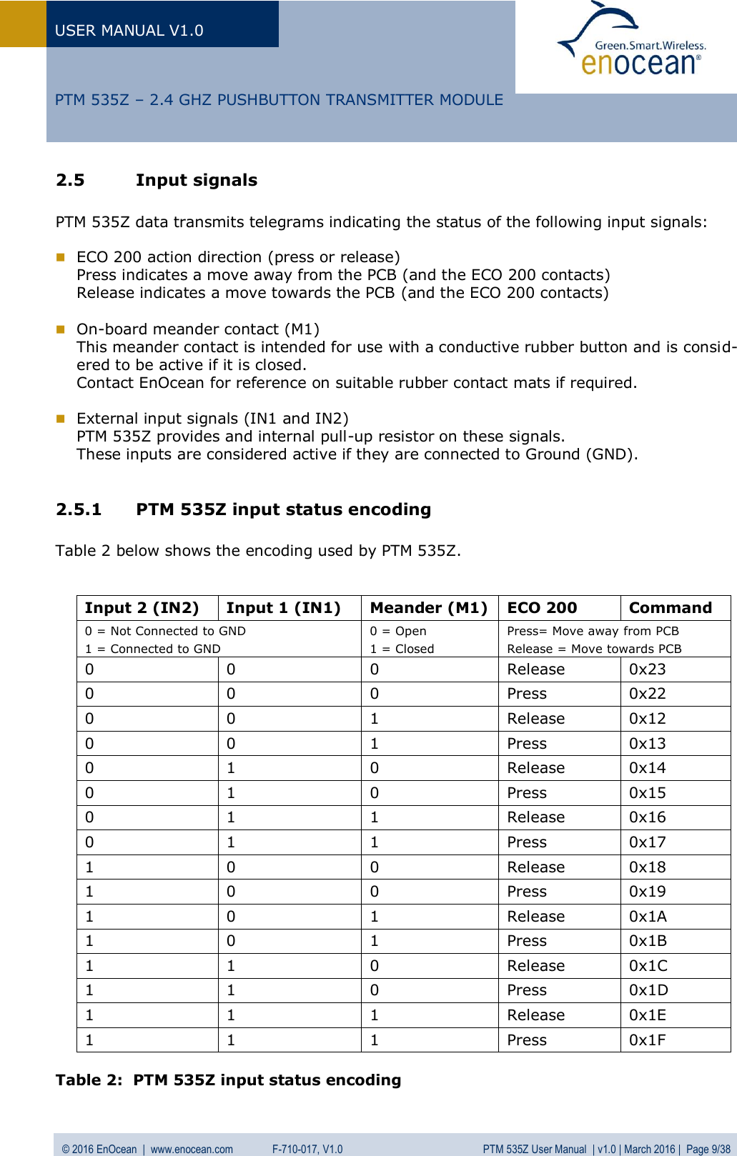
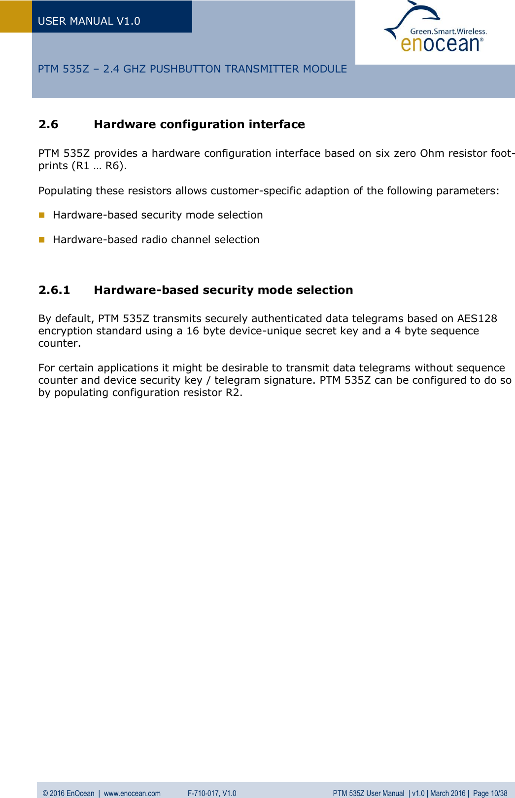
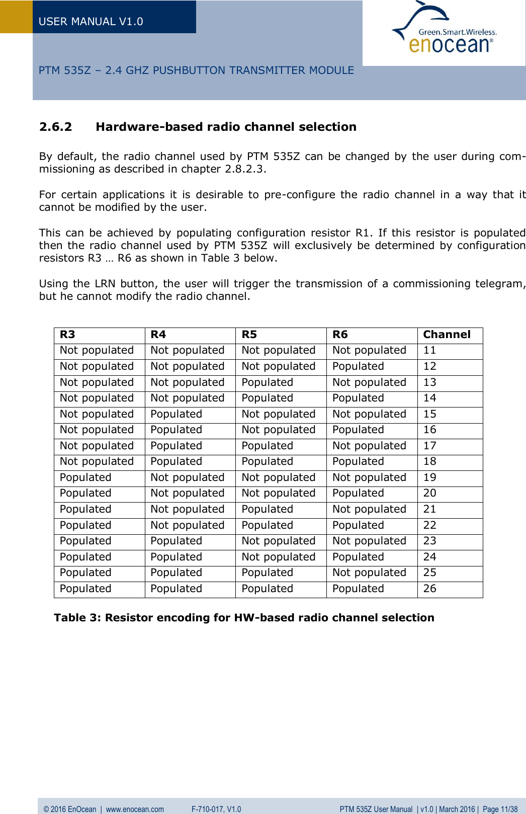
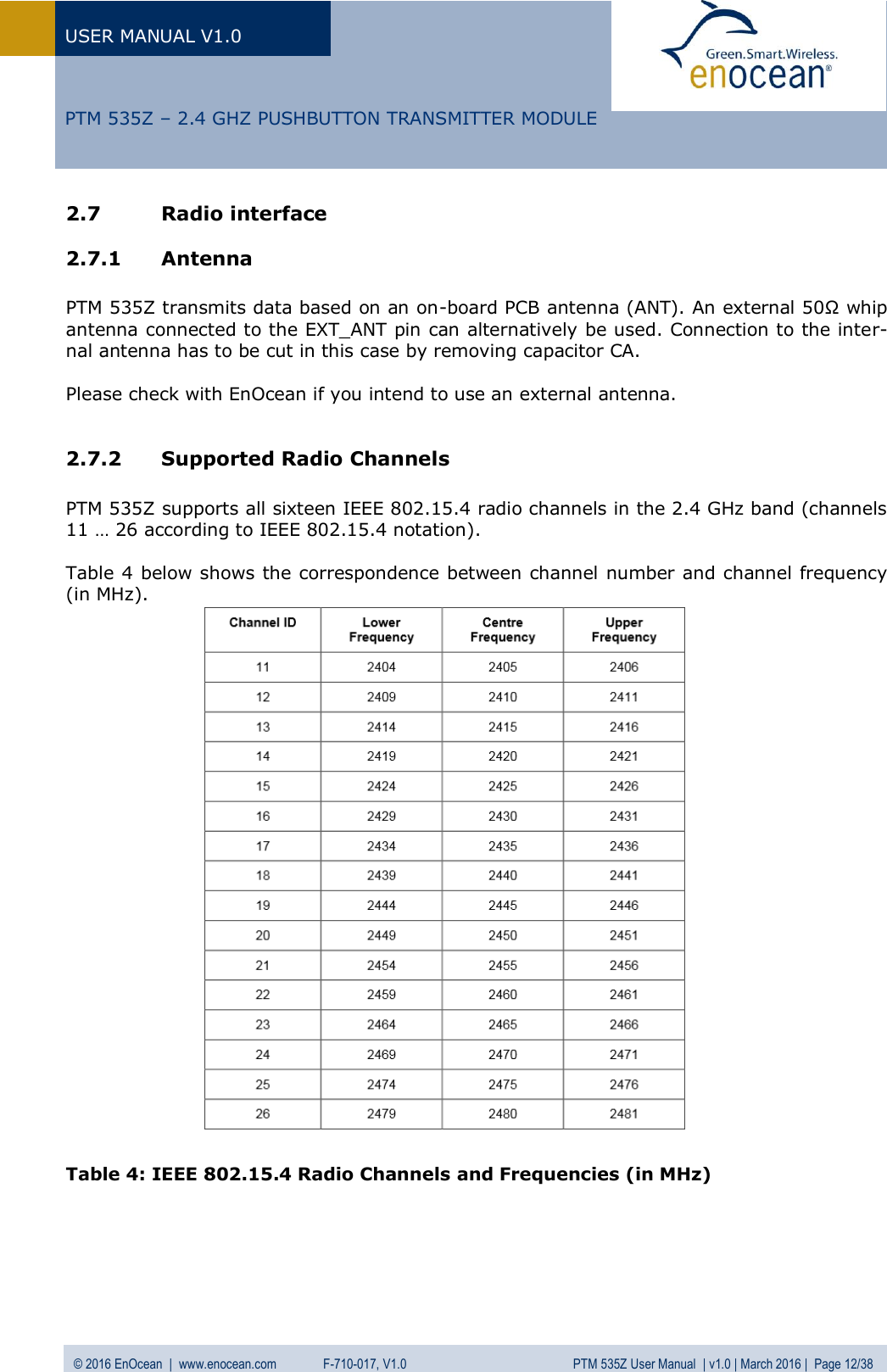
PTM535Z User Manual
User Manual
Navigation menu
Upload a User Manual
Namespaces
Wiki Guide
HTML
PDF
Info
Views
User Manual
Discussion / Help
Navigation