EnOcean STM110C 315 MHz Transmitter User Manual CERTIFICATE OF COMPLIANCE
EnOcean GmbH 315 MHz Transmitter CERTIFICATE OF COMPLIANCE
UserManual.wiki
>
EnOcean
>
STM110C User Manual
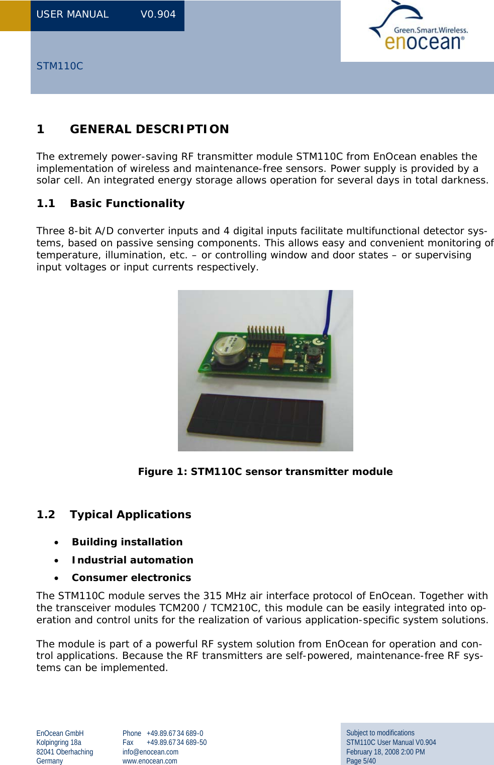
User Manual
Navigation menu
Upload a User Manual
Namespaces
Wiki Guide
HTML
PDF
Info
Views
User Manual
Discussion / Help
Navigation
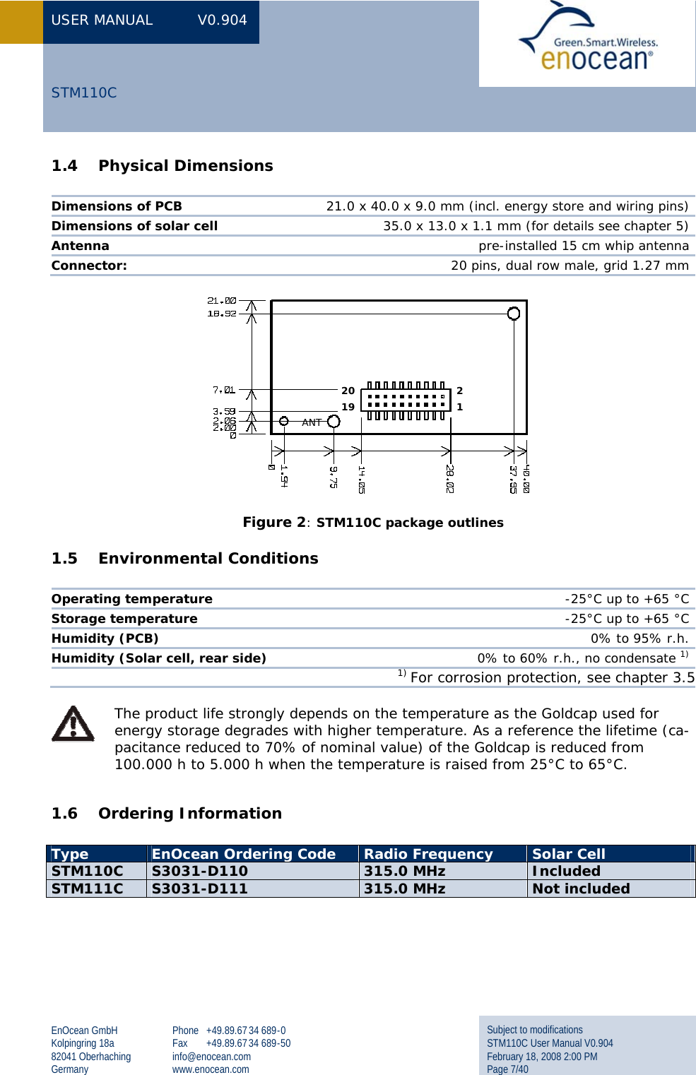
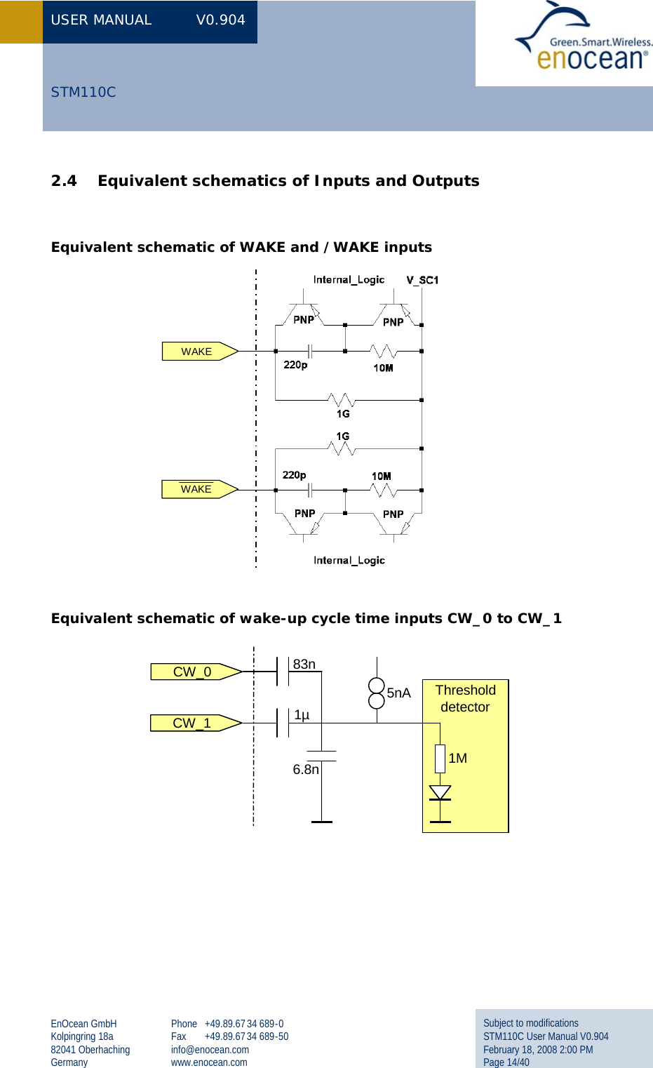
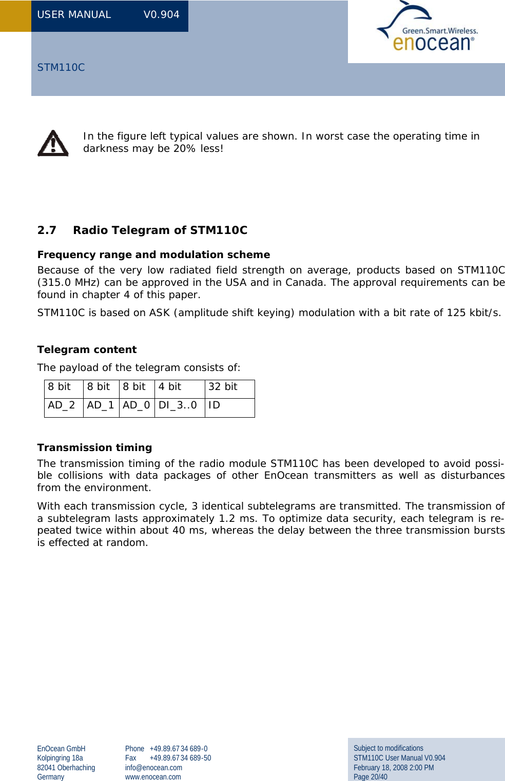
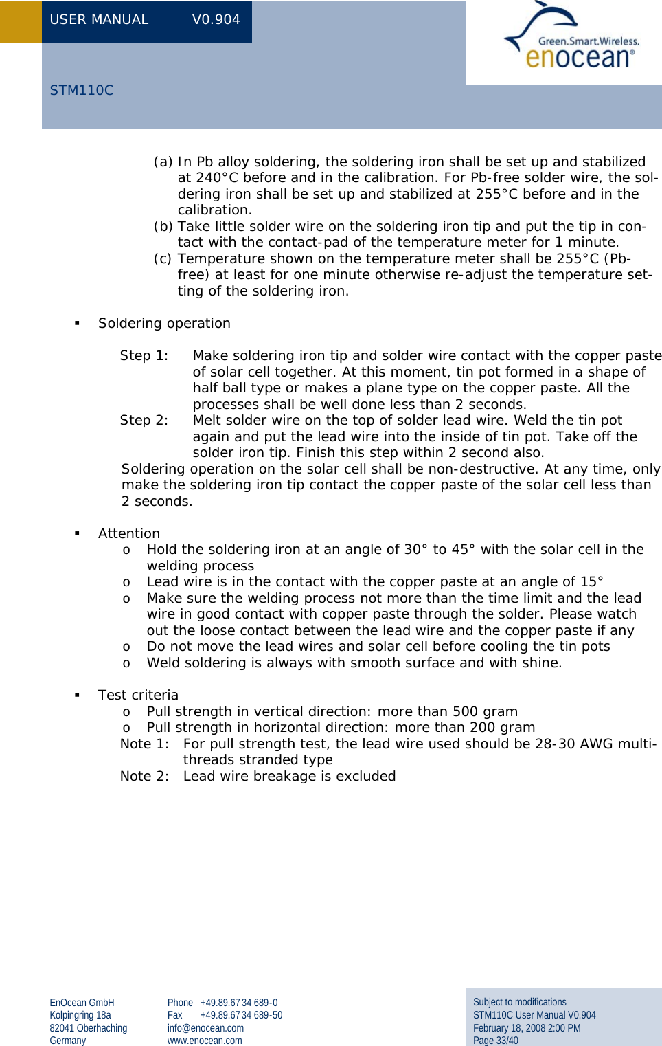
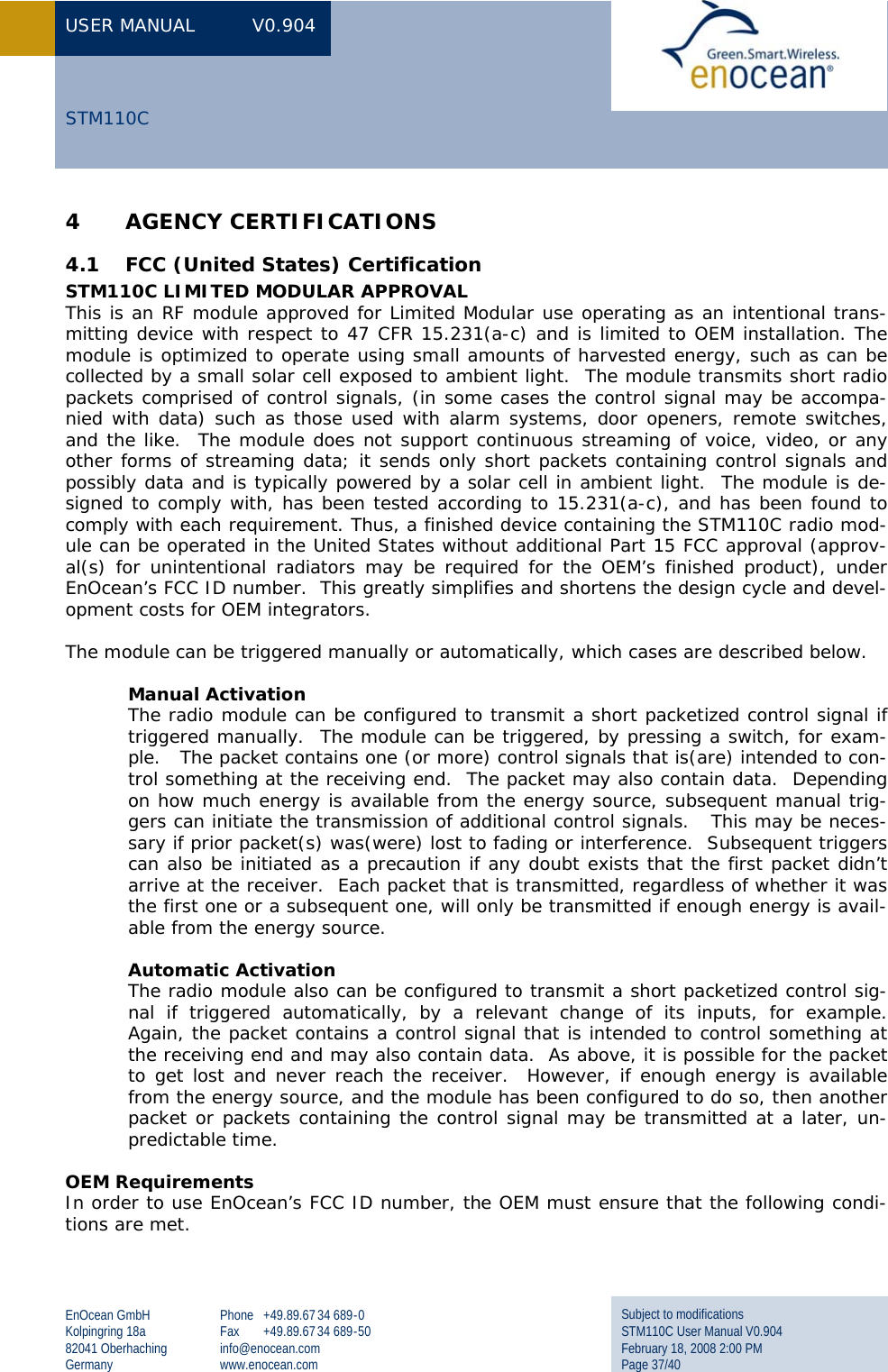
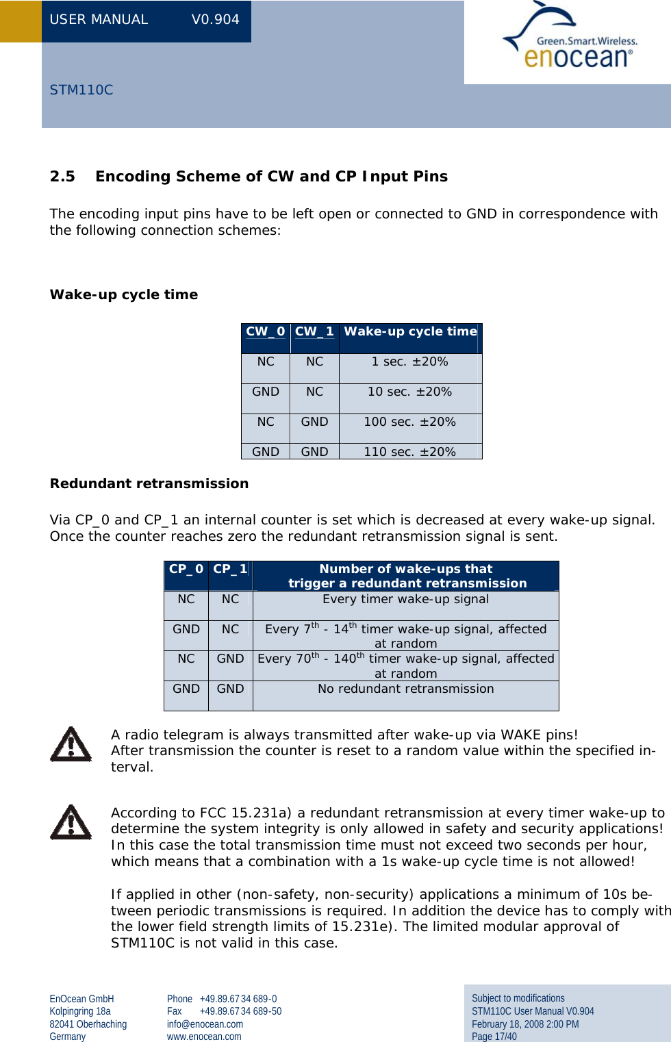
![USER MANUAL V0.904 EnOcean GmbH Kolpingring 18a 82041 Oberhaching Germany Phone +49.89.67 34 689-0 Fax +49.89.67 34 689-50 info@enocean.com www.enocean.com Subject to modifications STM110C User Manual V0.904 February 18, 2008 2:00 PM Page 15/40 STM110C Equivalent schematic of LED output Equivalent schematic of V_SC1 input R_C1: ~6 MΩ after 3 V applied for 10 min, >>10MΩ after 24h. R_STM: depends on wake-up cycle time, transmit intervals and supply voltage. In the following table R_STM is given at a supply voltage of 3V (typical values): R_STM [kΩ] 1s 10s 100s 110s Every wake-up 24 240 2400 2600 Every 10th wake-up (average) 63 630 6300 6900 Every 100th wake-up (average) 75 750 7500 8300 The current consumption is almost independent from the supply voltage (typical values): I_STM [µA] 1s 10s 100s 110s Every wake-up 130 13 1.3 1.1 Every 10th wake-up (average) 50 5.0 0.50 0.45 Every 100th wake-up (average) 40 4.0 0.40 0.35 V_SC1C1470µFR_C1R_STM](https://usermanual.wiki/EnOcean/STM110C/User-Guide-921035-Page-16.png)
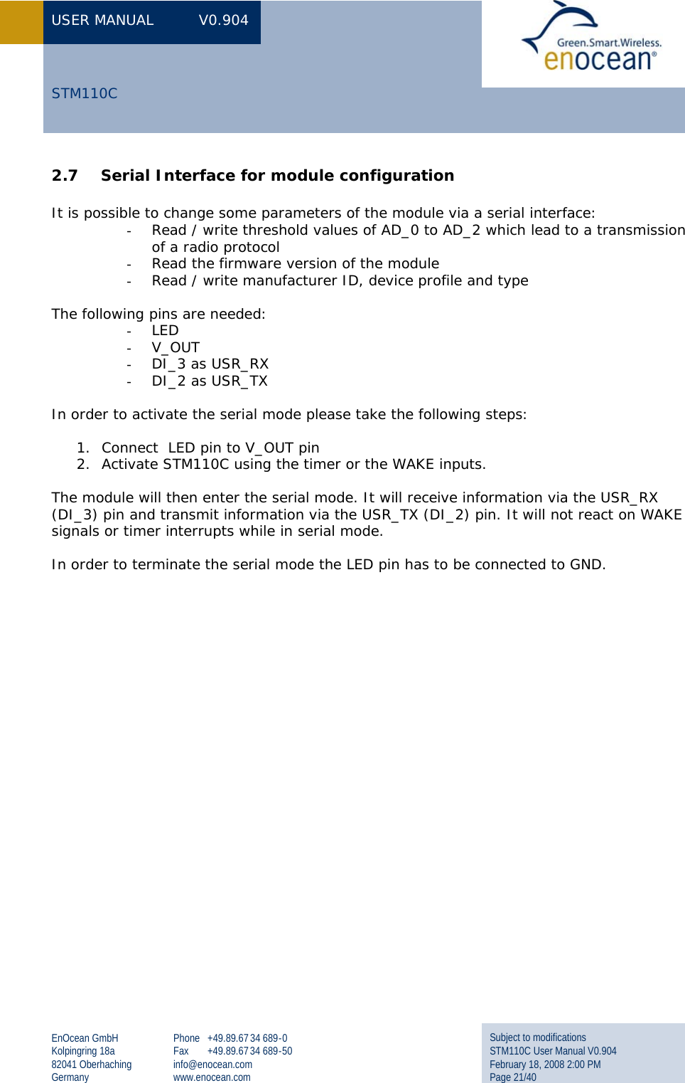
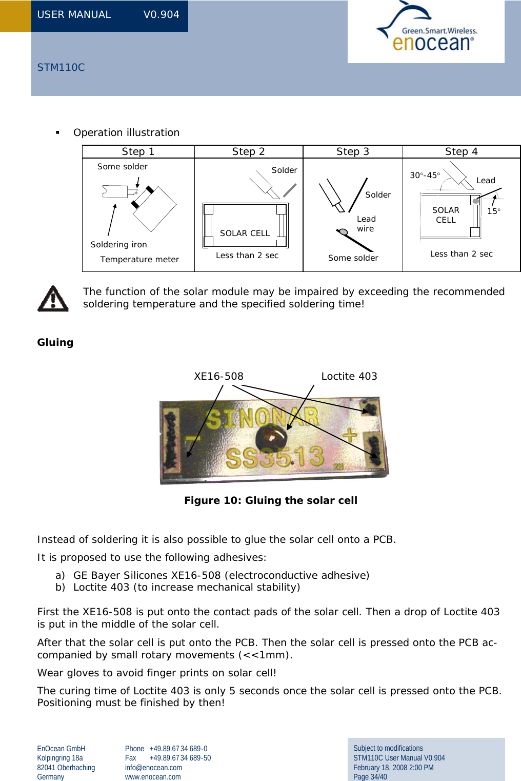
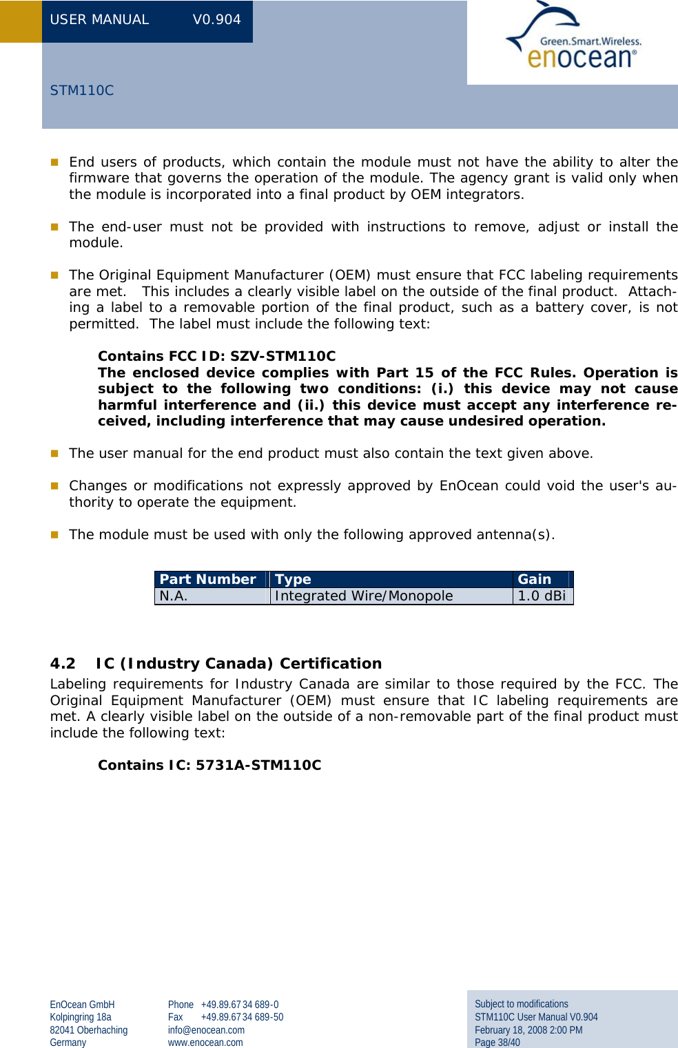
![USER MANUAL V0.904 EnOcean GmbH Kolpingring 18a 82041 Oberhaching Germany Phone +49.89.67 34 689-0 Fax +49.89.67 34 689-50 info@enocean.com www.enocean.com Subject to modifications STM110C User Manual V0.904 February 18, 2008 2:00 PM Page 18/40 STM110C 2.6 Solar Energy Balance Calculation The following diagrams are showing operational performance data of STM110C. Figure 5: Graphs of the goldcap charging process (typ. @25°C). Measured with white light LEDs, illustration of the illumination level as fluorescent lamp equiva-lent (EL). Measured with 100s wake up timer. 01234560 5 10 15 20 25charging time [h]Charging at 1000 lxCharging at 200 lxCharging at 50 lxCharging at 1000 lxCharging at 1000 lxCharging at 200 lxCharging at 50 lxVoltage V_SC2[V]Charging time [h]](https://usermanual.wiki/EnOcean/STM110C/User-Guide-921035-Page-19.png)
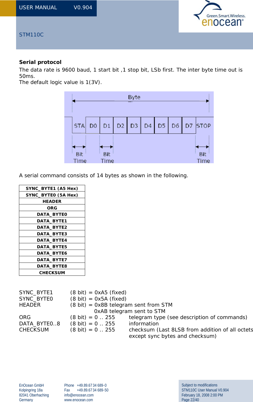
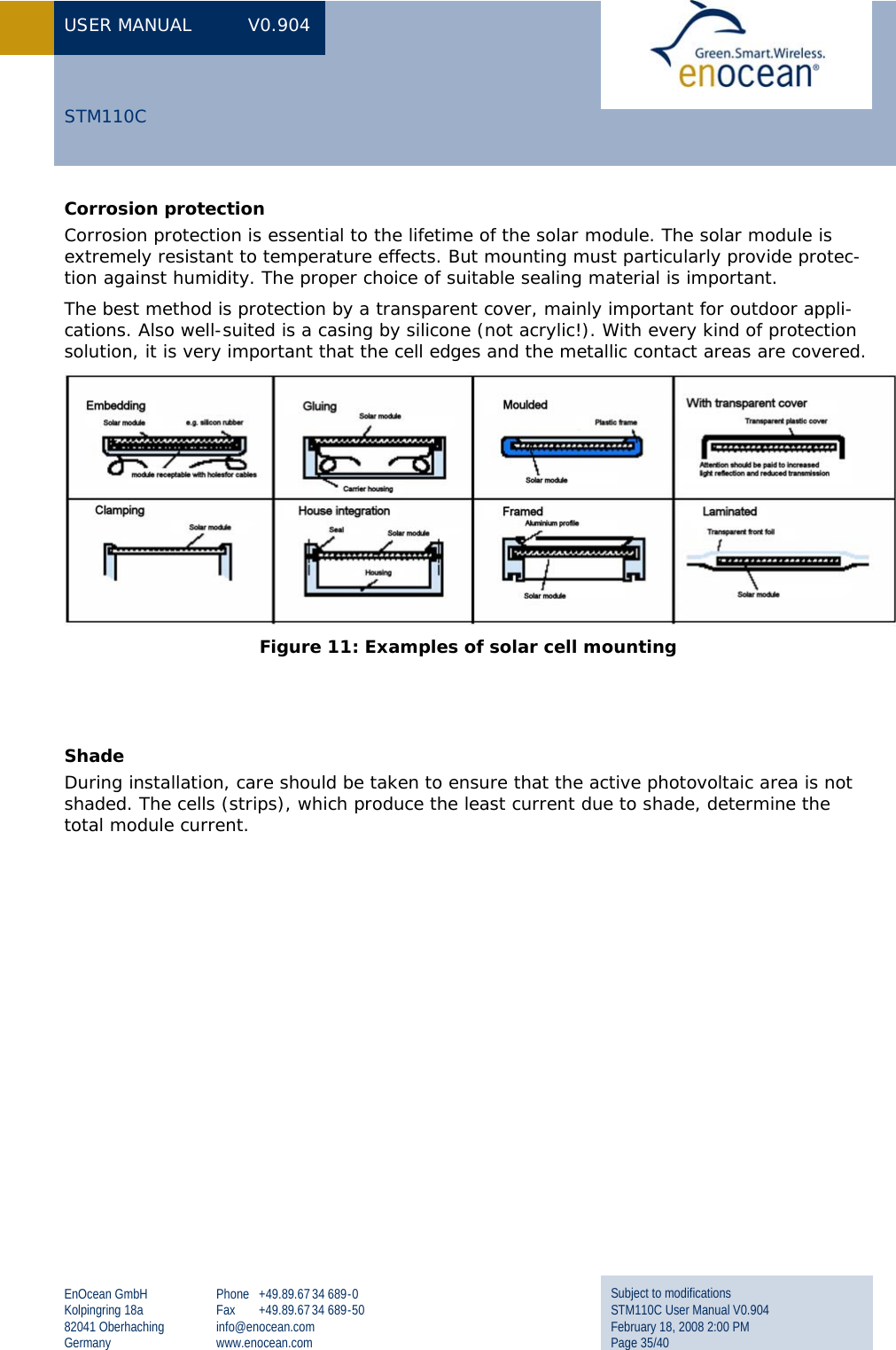
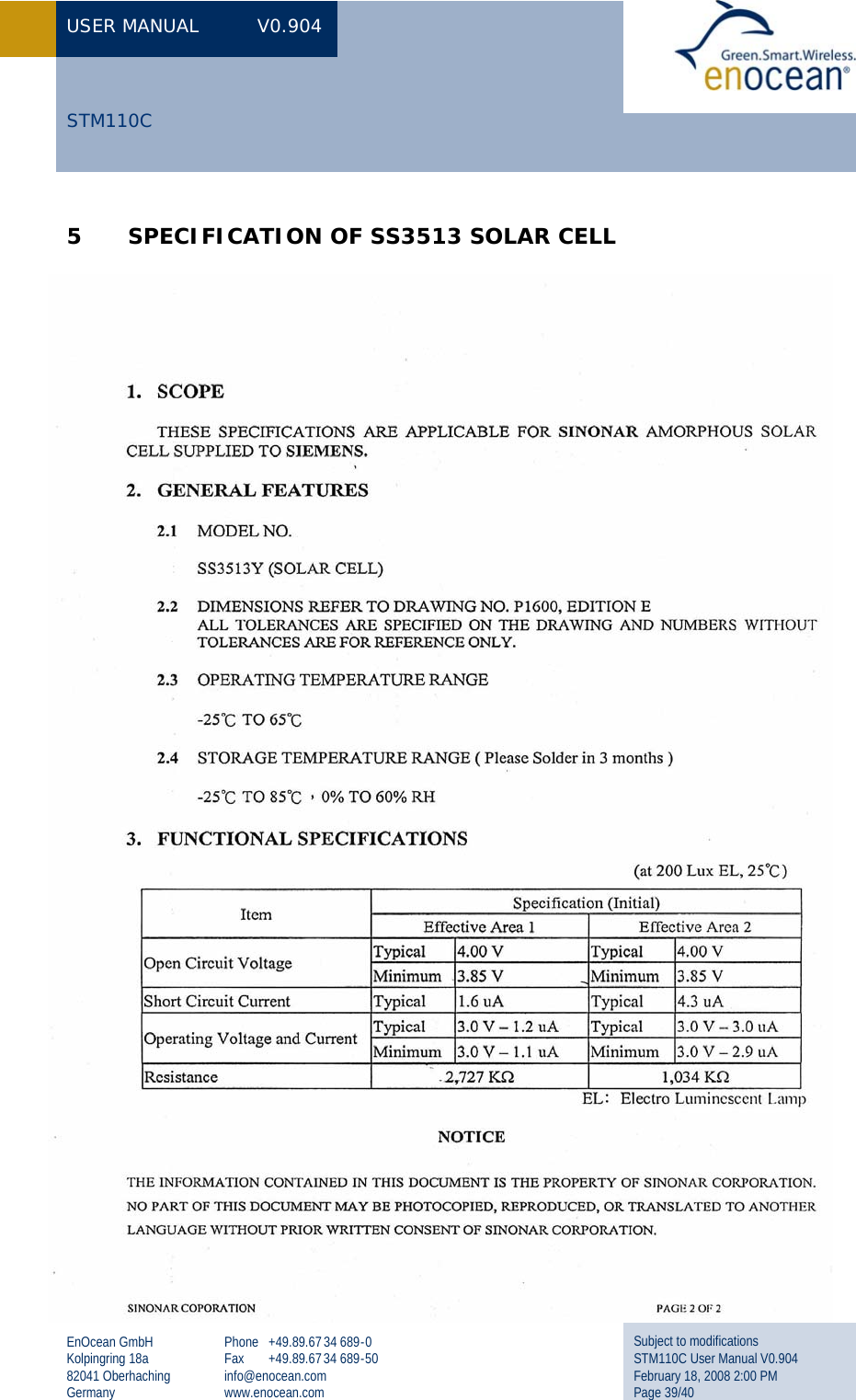
![USER MANUAL V0.904 EnOcean GmbH Kolpingring 18a 82041 Oberhaching Germany Phone +49.89.67 34 689-0 Fax +49.89.67 34 689-50 info@enocean.com www.enocean.com Subject to modifications STM110C User Manual V0.904 February 18, 2008 2:00 PM Page 19/40 STM110C 0123456051015202530Operating time in darkness [h]Voltage V_SC1 [V]10 sec timer01234560123Operating time in darkness [h]Voltage V_SC1 [V]1 sec timer01234560306090120150Operating time in darkness [h]Voltage V_SC1 [V]100 sec timerTelegram transmission at every wake upTelegram transmission every 10th wake upTelegram transmission every 100th wake upTelegram transmission at every wake upTelegram transmission every 10th wake upTelegram transmission every 100th wake upVoltage V_SC2[V] Voltage V_SC2[V]Voltage V_SC2[V] Voltage V_SC2[V]Operating time in darkness [h]Operating time in darkness [h]Operating time in darkness [h] Figure 6: STM110C operation time in darkness (typ. @25°C) (average) (average)](https://usermanual.wiki/EnOcean/STM110C/User-Guide-921035-Page-20.png)