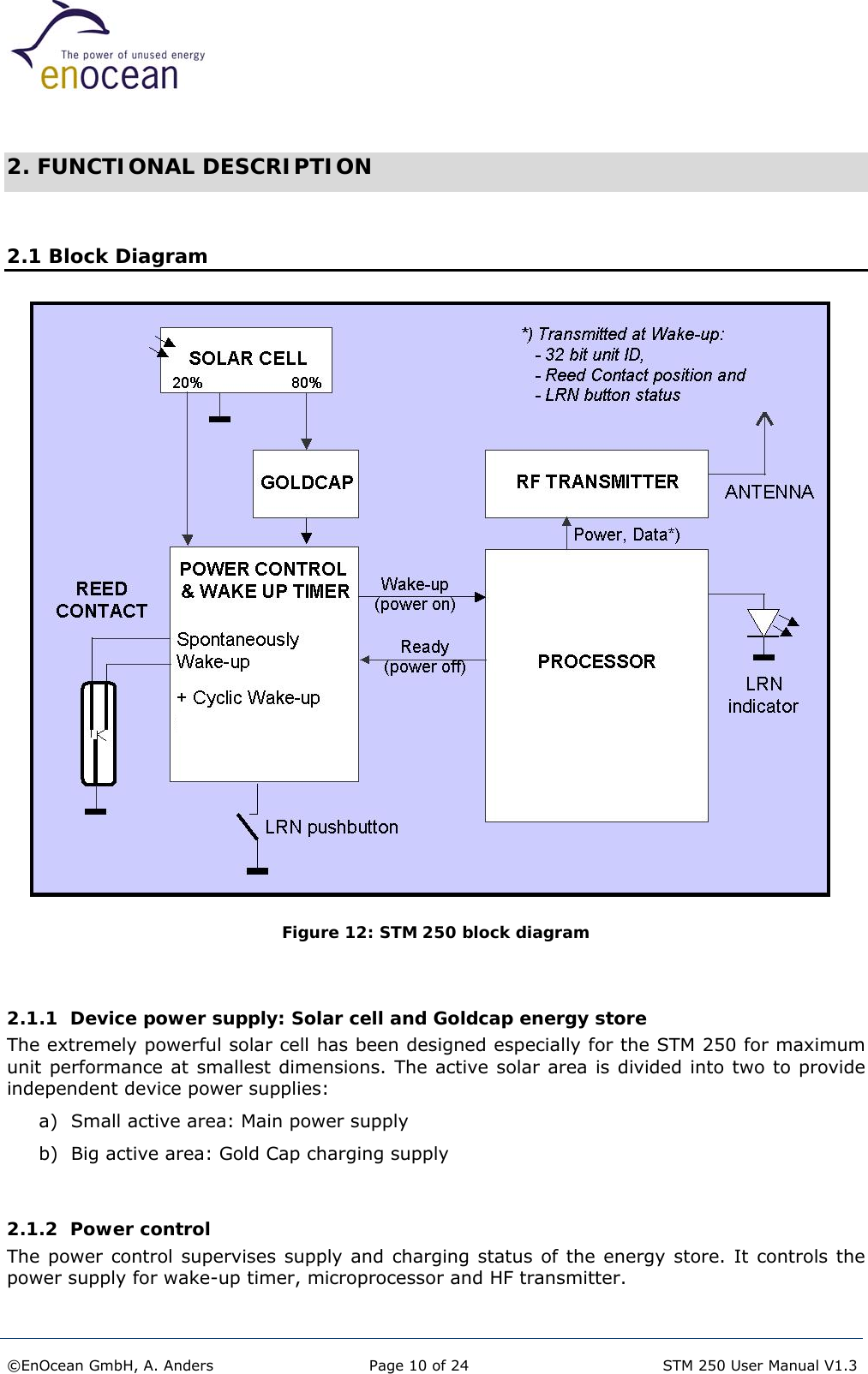
EnOcean STM250 Wireless Burglar Alarm for Windows User Manual STM 250
EnOcean GmbH Wireless Burglar Alarm for Windows STM 250
UserManual.wiki
>
EnOcean
>
STM250 User Manual
User Manual
Navigation menu
Upload a User Manual
Namespaces
Wiki Guide
HTML
PDF
Info
Views
User Manual
Discussion / Help
Navigation


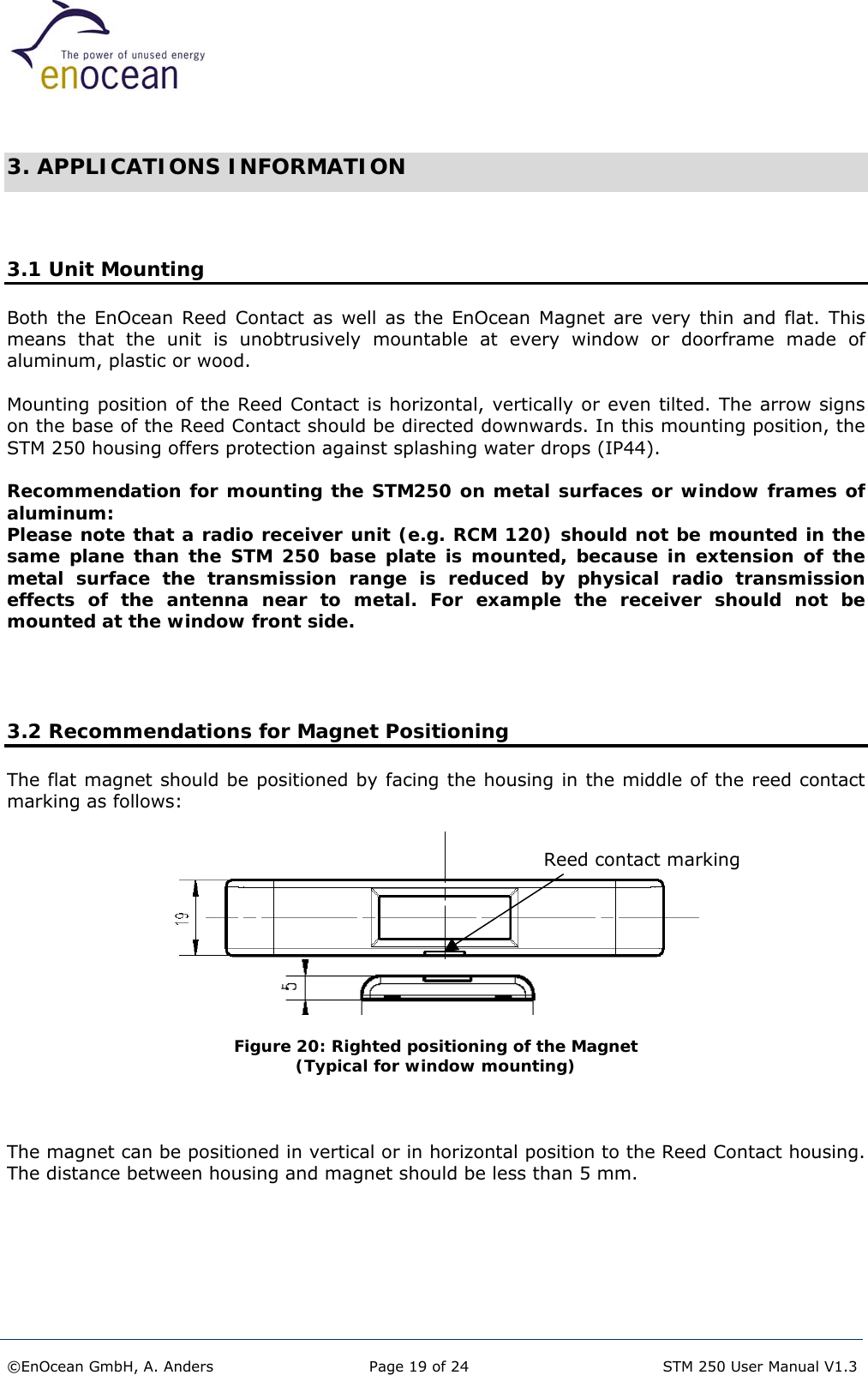
![2.2 Solar Energy Balance Calculation In the following diagrams, you will find the energy store operation characteristics under the condition that the number of reed contact operations can be neglected compared to cyclic sending times of the presence signal (normal operation in practice). Negligible implies that reed contact operations are less than 10 times a day. Notes: • Configuration of the Goldcap energy store: To obtain the Goldcap nominal capacity some charging/discharging cycles are needed. Because of that, the initial operating time at total darkness could be shorter as given below. • Continuously operation at temperatures higher than 50°C could decrease the capacity of the Goldcap during lifetime. This will result in shorter charging times and shorter operating times in total darkness. 2.2.1 Initial loading time for one-night operation Illumination time for loading empty energy storeto 14 h operation in total darkness (typ. values)048121620100 1000illumination [lux]loading time [hours] Figure 13 ©EnOcean GmbH, A. Anders Page 12 of 24 STM 250 User Manual V1.3](https://usermanual.wiki/EnOcean/STM250/User-Guide-533757-Page-12.png)
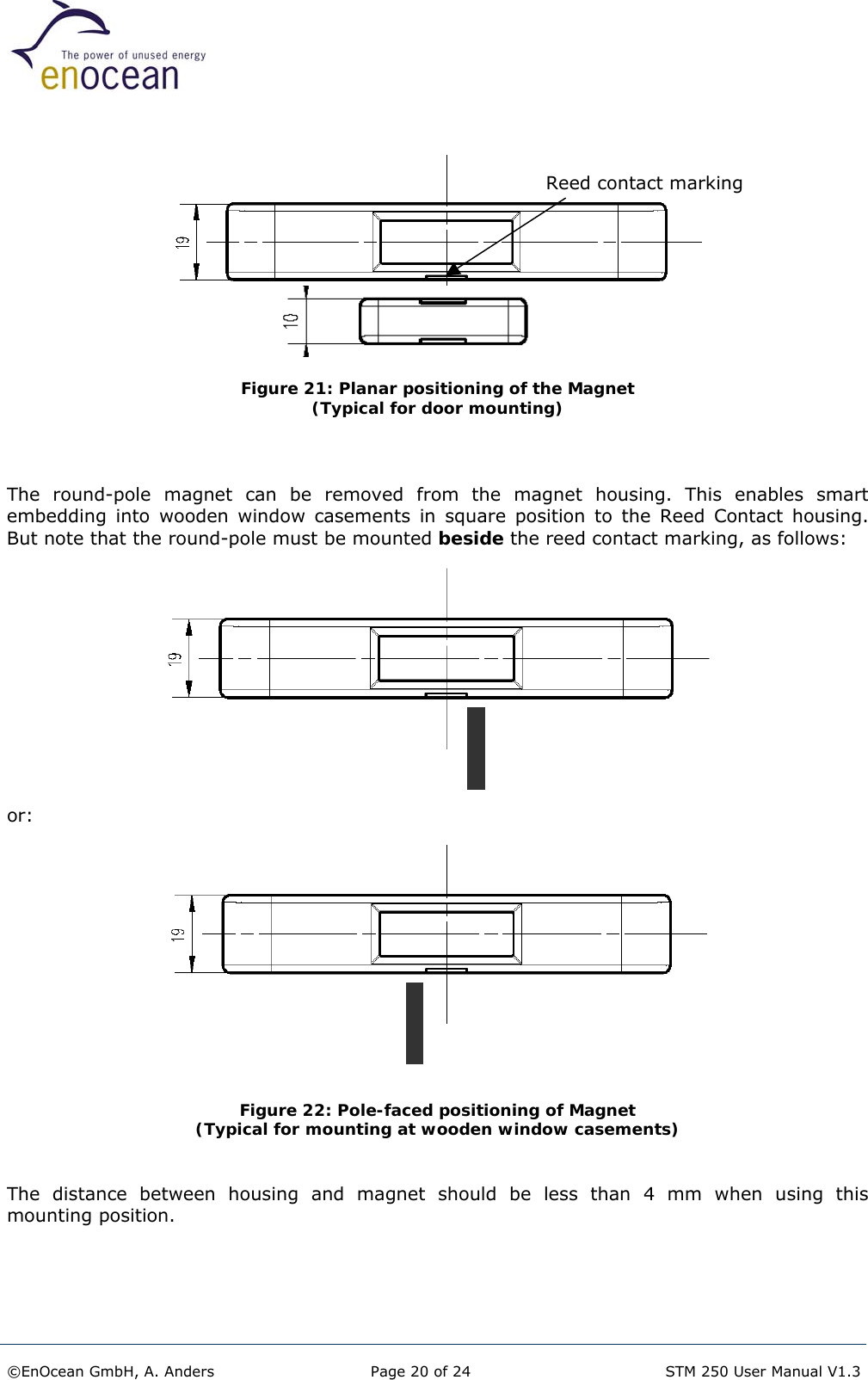
![2.2.2 Reload time for one-night operation Illumination time for reloading energy store from working limitto 14 h operation in total darkness (typ. values)010203040100 1000illumination [lux]reload time [minutes] Figure 14 2.2.3 Initial load time for filling energy store to capacity Load time STM 250 versus illumination of Goldcap from working limit to 90% of max. loading voltage (typ. values)1234567100 200 300 400 500 600 700 800 900 1000illumination [Lux]load time [hours] Figure 15 ©EnOcean GmbH, A. Anders Page 13 of 24 STM 250 User Manual V1.3](https://usermanual.wiki/EnOcean/STM250/User-Guide-533757-Page-13.png)
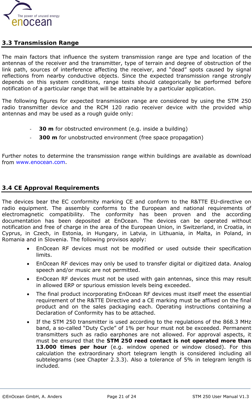
![2.2.4 Maximum operation time in total darkness STM 250 operation time in total darkness (typ. values, initial loading of Goldcap is 90% of max. loading voltage)0246810100 1000illuminance on average [Lux]operation time [days] Figure 16 ©EnOcean GmbH, A. Anders Page 14 of 24 STM 250 User Manual V1.3](https://usermanual.wiki/EnOcean/STM250/User-Guide-533757-Page-14.png)