EnOcean STM300U TRANSCEIVER MODULE User Manual 1
EnOcean GmbH TRANSCEIVER MODULE 1
UserManual.wiki
>
EnOcean
>
STM300U User Manual
>
User Manual 1
Contents
1.
User Manual 1
2.
User Manual 2
3.
User Manual 3
4.
USER MANUAL 1
5.
USER MANUAL 2
User Manual 1
Navigation menu
Upload a User Manual
Namespaces
Wiki Guide
HTML
PDF
Info
Views
User Manual
Discussion / Help
Navigation
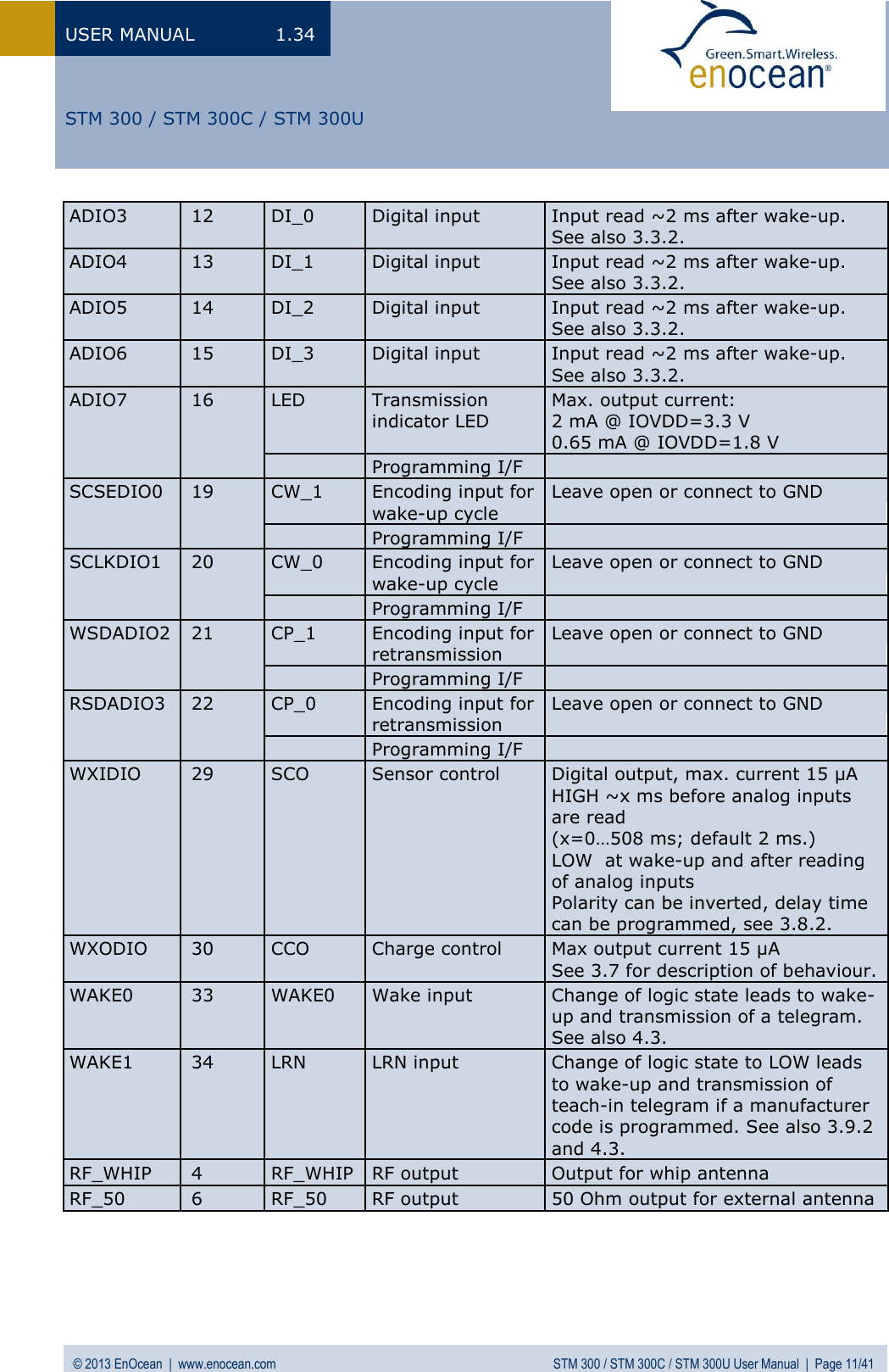
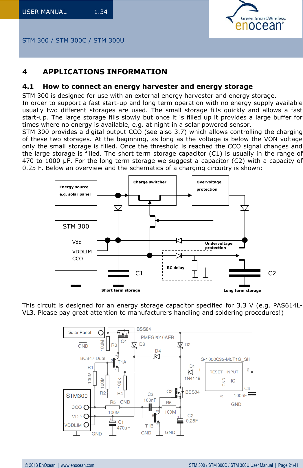
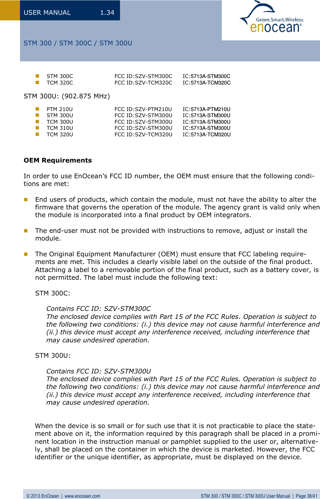
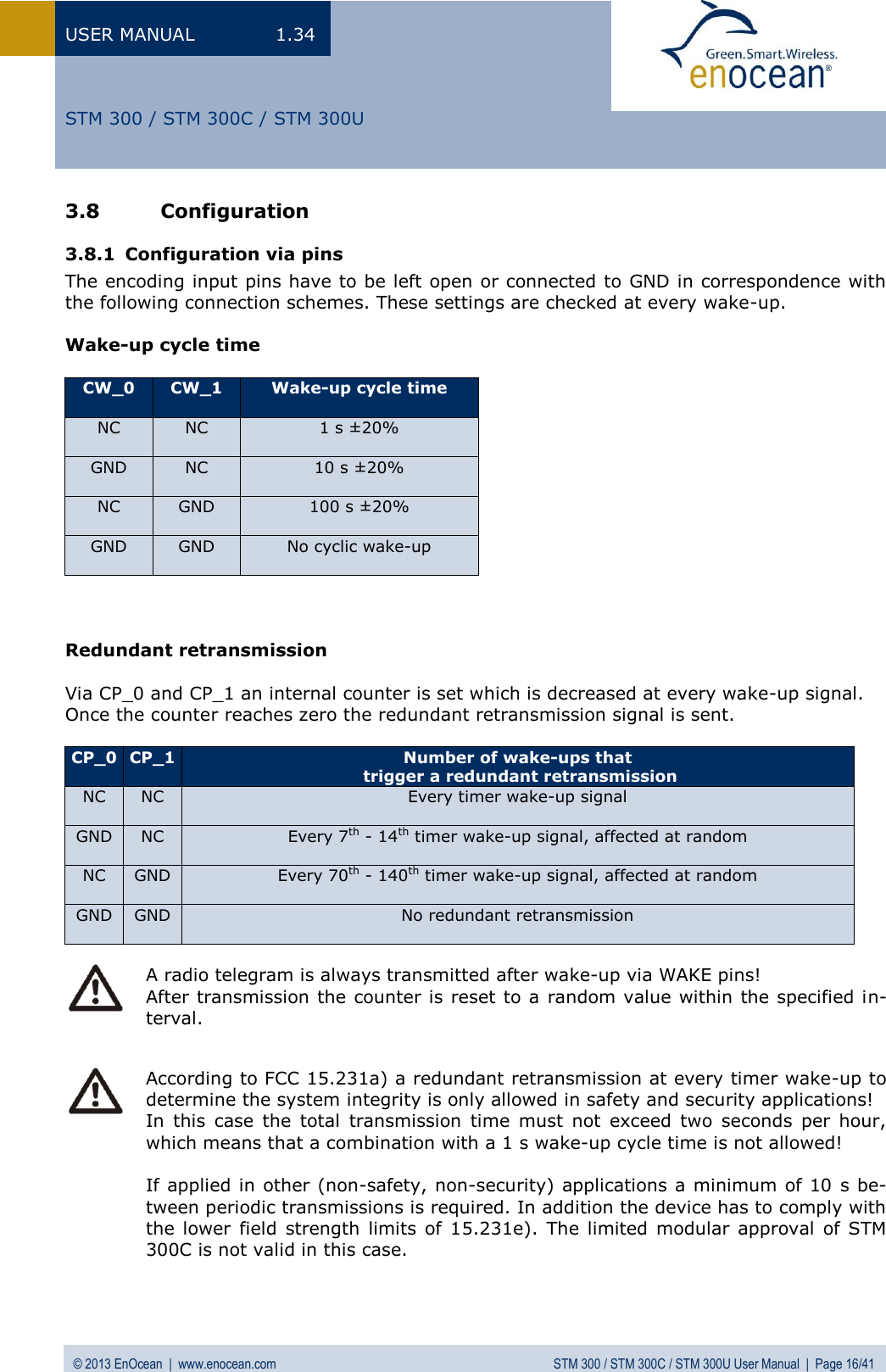
![USER MANUAL 1.34 © 2013 EnOcean | www.enocean.com STM 300 / STM 300C / STM 300U User Manual | Page 13/41 STM 300 / STM 300C / STM 300U 100x000xFFidealrealOffset ErrorGain ErrorCodeADCUADCURVDD3.3.2 Analog and digital inputs Parameter Conditions / Notes Min Typ Max Units Analog Input Mode Measurement range Single ended Internal reference RVDD/2 0.067 RVDD-0.12 V Input coupling DC Measurement bandwidth1 62.5 kHz Input impedance Single ended against GND @ 1 kHz 10 M Input capacitance Single ended against GND @ 1 kHz 10 pF Effective measurement resolution 10 Bit 10 bit measurement Offset error 23 36 LSB Gain error 32 62 LSB INL Code <=200 +3 -14 +6 -23 LSB Code >200 +3 -4 +6 -10 LSB DNL <±0.5 LSB 8 bit measurement Offset error 6 9 LSB Gain error 8 16 LSB INL Code <=50 +1 -4 +2 -6 LSB Code >50 +1 -1 +2 -3 LSB DNL <±0.125 LSB Offset Error: Describes the offset between the minimal possible code and code 0x00. Gain Error: Describes the offset between maximum possible code and full scale (e.g. 0x3FF for 10 bit measurements). Integral Non-Linearity (INL): Describes the difference between the ideal characteristics and the real characteristics. Only values between minimum and maximum possible code are considered (excluding offset error and gain error). Differential Non-Linearity (DNL): Measures the maximum deviation from the ideal step size of 1 LSB (least significant bit). Effective resolution: Results from the signal-noise ratio of the ADC and is given in Bit. The number describes how many bits can be measured stable. The criterion selected here is that the noise of DNL is <±0.5 LSB. Measurement Bandwidth: The measurement bandwitdh is internally limited by filters. A quasi static signal must be applied as long as the filter needs to settle. SettlingTime= 1/(MeasurementBandwidth)*ln(2^resolution[Bit]) For further details please refer to the Dolphin Core Description. 1 3 dB input bandwidth, resulting in 111 µs settling time to achieve a deviation of an input signal <1 LSB (<0.098% @ 10 bit resolution).](https://usermanual.wiki/EnOcean/STM300U.User-Manual-1/User-Guide-1908331-Page-13.png)
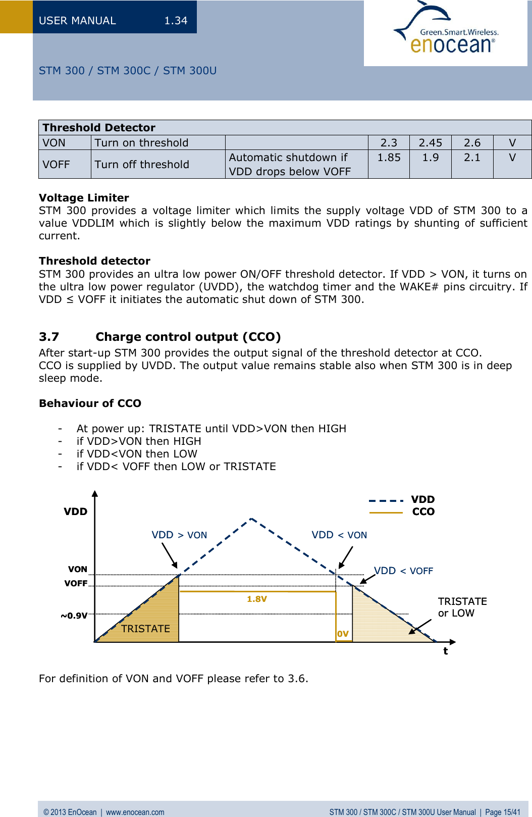
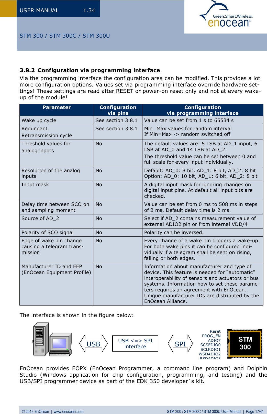
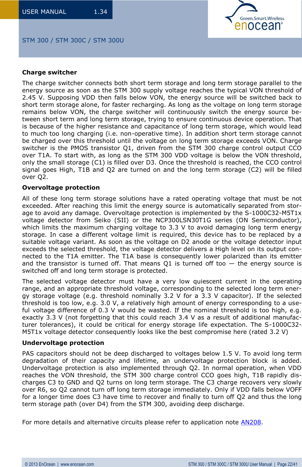
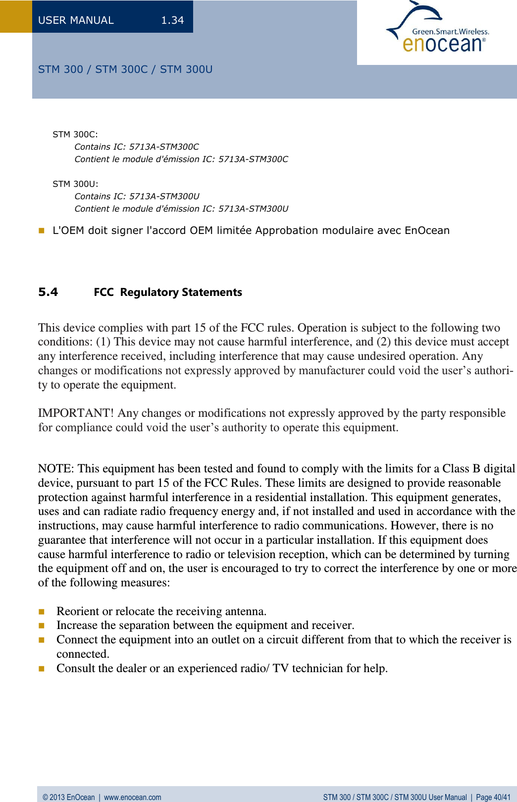
![USER MANUAL 1.34 © 2013 EnOcean | www.enocean.com STM 300 / STM 300C / STM 300U User Manual | Page 20/41 STM 300 / STM 300C / STM 300U 3.11 Energy consumption Current Consumption of STM 300 Charge needed for one measurement and transmit cycle: ~130 µC Charge needed for one measurement cycle without transmit: ~30 µC (current for external sensor circuits not included) Calculations are performed on the basis of electric charges because of the internal linear voltage regulator of the module. Energy consumption varies with voltage of the energy storage while consumption of electric charge is constant. From these values the following performance parameters have been calculated: Wake cycle [s] Transmit interval Operation Time in darkness [h] when storage fully charged Required reload time [h] at 200 lux within 24 h for continuous operation 24 h operation after 6 h illumination at x lux Illumina-tion level in lux for continuous operation Current in µA required for con-tinuous operation 1 1 0.5 storage too small storage too small 5220 130.5 1 10 1.7 storage too small storage too small 1620 40.5 1 100 2.1 storage too small storage too small 1250 31.3 10 1 5.1 storage too small storage too small 540 13.5 10 10 16 21 storage too small 175 4.4 10 100 20 16.8 storage too small 140 3.5 100 1 43 7.8 260 65 1.6 100 10 98 3.6 120 30 0.8 100 100 112 3 100 25 0.6 Assumptions: Storage PAS614L-VL3 with 0.25 F, Umax=3.2 V, Umin=2.2 V, T=25°C Consumption: Transmit cycle 100 µC, measurement cycle 30 µC Indoor solar cell, operating values 3 V and 5 µA @ 200 lux fluorescent light (e.g. ECS 300 solar cell) Current proportional to illumination level (not true at very low levels!) These values are calculated values, the accuracy is about +/-20%! 0.000010.00010.0010.010.1110100010 20 30 40 50 60 70 80 90 100Time [ms]Current [mA]](https://usermanual.wiki/EnOcean/STM300U.User-Manual-1/User-Guide-1908331-Page-20.png)