User Manual

USER MANUA
L
V0.6
EnOcean GmbH
Kolpingring 18a
82041 Oberhaching
Germany
Phone +49.89.67 34 689-0
Fax +49.89.67 34 689-50
info@enocean.com
www.enocean.com
Subject to modifications
STM 31x / STM 31xC User Manual V0.6
September 7, 2010 3:58 PM
Page 1/28
Patent protected:
WO98/36395, DE 100 25 561, DE 101 50 128,
WO 2004/051591, DE 103 01 678 A1, DE 10309334,
WO 04/109236, WO 05/096482, WO 02/095707,
US 6,747,573, US 7,019,241
Observe precautions! Electrostatic sensitive devices!
Scavenger Transmitter Module
STM 31x / STM 31xC
September 7, 2010

USER MANUA
L
V0.6
© 2010 EnOcean | www.enocean.com STM 31x / STM 31xC User Manual V0.6 | Page 2
/
28
STM 31X / STM 31XC
REVISION HISTORY
The following major modifications and improvements have been made to the first version of
this document:
No Major Changes
0.5 Initial version
0.6 New drawings added, Agency approvals added
Published by EnOcean GmbH, Kolpingring 18a, 82041 Oberhaching, Germany
www.enocean.com, info@enocean.com, phone ++49 (89) 6734 6890
© EnOcean GmbH
All Rights Reserved
Important!
This information describes the type of component and shall not be considered as assured characteris-
tics. No responsibility is assumed for possible omissions or inaccuracies. Circuitry and specifications
are subject to change without notice. For the latest product specifications, refer to the EnOcean web-
site: http://www.enocean.com.
As far as patents or other rights of third parties are concerned, liability is only assumed for modules,
not for the described applications, processes and circuits.
EnOcean does not assume responsibility for use of modules described and limits its liability to the
replacement of modules determined to be defective due to workmanship. Devices or systems contain-
ing RF components must meet the essential requirements of the local legal authorities.
The modules must not be used in any relation with equipment that supports, directly or indirectly,
human health or life or with applications that can result in danger for people, animals or real value.
Components of the modules are considered and should be disposed of as hazardous waste. Local
government regulations are to be observed.
Packing: Please use the recycling operators known to you. By agreement we will take packing mate-
rial back if it is sorted. You must bear the costs of transport. For packing material that is returned to
us unsorted or that we are not obliged to accept, we shall have to invoice you for any costs incurred.

USER MANUA
L
V0.6
© 2010 EnOcean | www.enocean.com STM 31x / STM 31xC User Manual V0.6 | Page 3
/
28
STM 31X / STM 31XC
TABLE OF CONTENT
1 GENERAL DESCRIPTION................................................................................. 4
1.1 Basic functionality ......................................................................................... 4
1.2 Technical data .............................................................................................. 5
1.3 Physical dimensions....................................................................................... 5
1.4 Environmental conditions ............................................................................... 7
1.5 Ordering Information ..................................................................................... 7
2 FUNCTIONAL DESCRIPTION............................................................................ 8
2.1 Simplified firmware flow chart and block diagram.............................................. 8
2.2 Pin out ......................................................................................................... 9
2.3 Pin description and operational characteristics ................................................ 10
2.3.1 Interface supply voltage........................................................................... 11
2.3.2 Analog and digital inputs .......................................................................... 12
2.4 Absolute maximum ratings (non operating) .................................................... 12
2.5 Maximum ratings (operating)........................................................................ 12
2.6 Power management and voltage regulators .................................................... 13
2.7 Configuration.............................................................................................. 13
2.7.1 Configuration via pins .............................................................................. 13
2.7.2 Configuration via serial interface ............................................................... 15
2.8 Radio telegram ........................................................................................... 16
2.8.1 Normal operation .................................................................................... 16
2.8.2 Teach-in telegram ................................................................................... 17
2.9 Transmit timing .......................................................................................... 17
2.10 Charging circuitry................................................................................... 18
2.11 Energy consumption ............................................................................... 18
3 APPLICATIONS INFORMATION ...................................................................... 20
3.1 Using the WAKE pins ................................................................................... 20
3.2 Antenna options.......................................................................................... 22
3.2.1 Whip antenna (STM 310, STM 310C, STM 312, STM 312C) ........................... 22
3.2.2 Helical antenna (STM 311, STM 311C) ....................................................... 23
3.3 Transmission range ..................................................................................... 24
4 AGENCY CERTIFICATIONS ............................................................................ 25
4.1 CE Approval................................................................................................ 25
4.2 FCC (United States) certification ................................................................... 26
4.3 IC (Industry Canada) certification.................................................................. 28
USER MANUA
L
V0.6
© 2010 EnOcean | www.enocean.com STM 31x / STM 31xC User Manual V0.6 | Page 4
/
28
STM 31X / STM 31XC
1 GENERAL DESCRIPTION
1.1 Basic functionality
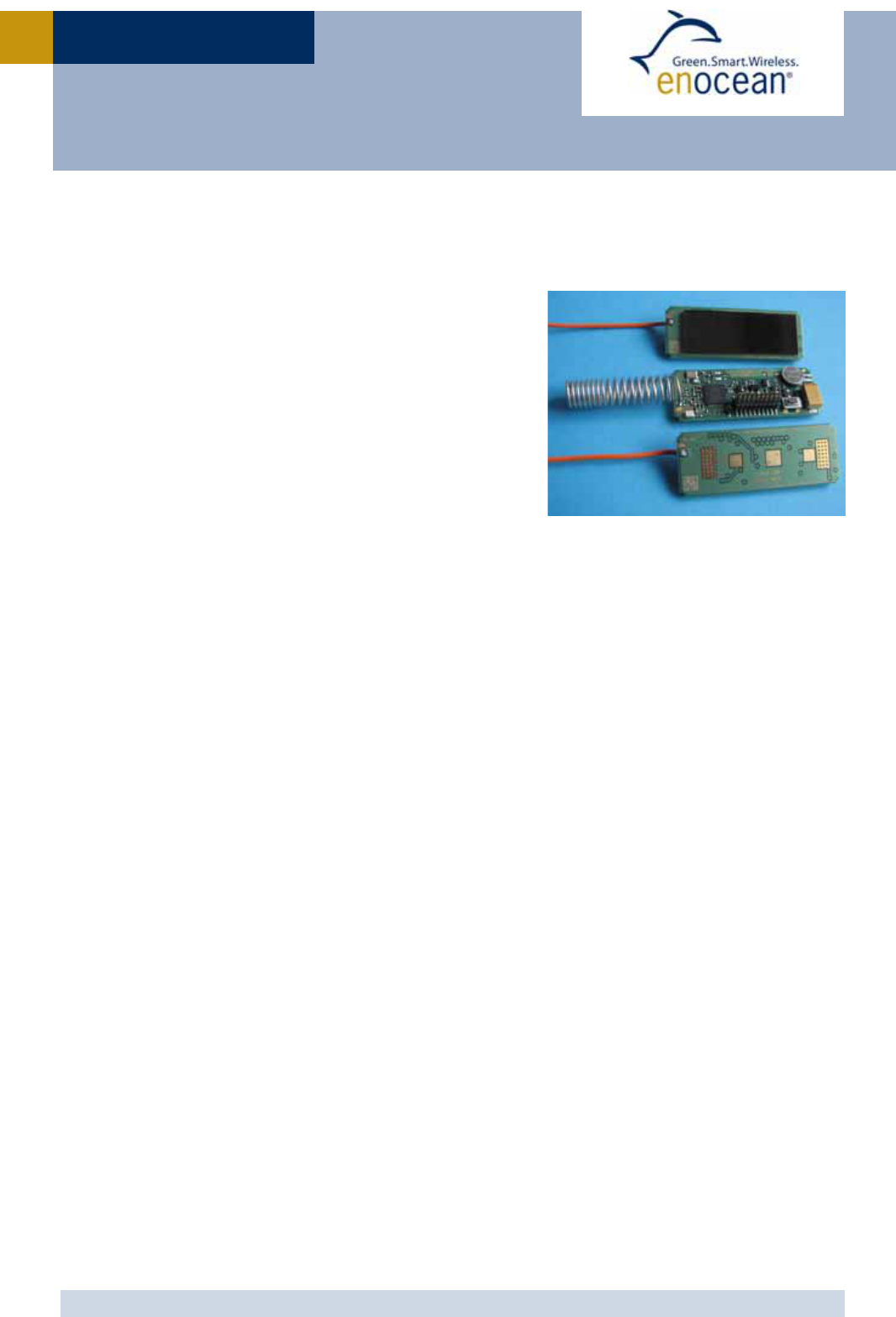
The extremely power saving RF transmitter module
STM 31x of EnOcean enables the realization of a wide
range of wireless and maintenance free sensors such
as temperature sensors, humidity sensors, or room
operating panels.
Power supply is provided by a small solar cell, an ex-
ternal energy harvester, or an external 3V battery. An
energy storage is installed to bridge periods with no
supply from the energy harvester. The module pro-
vides a user configurable cyclic wake up.
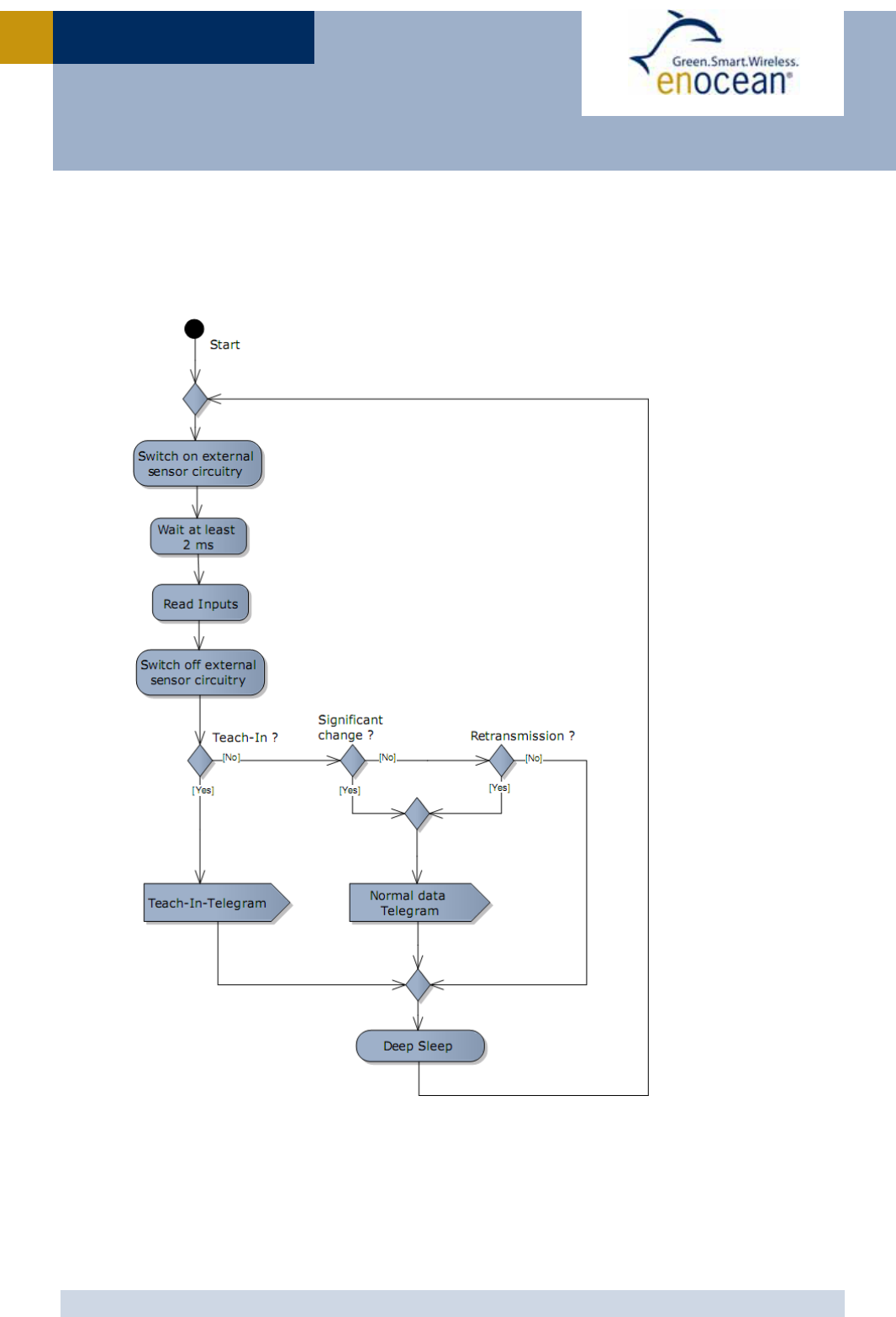
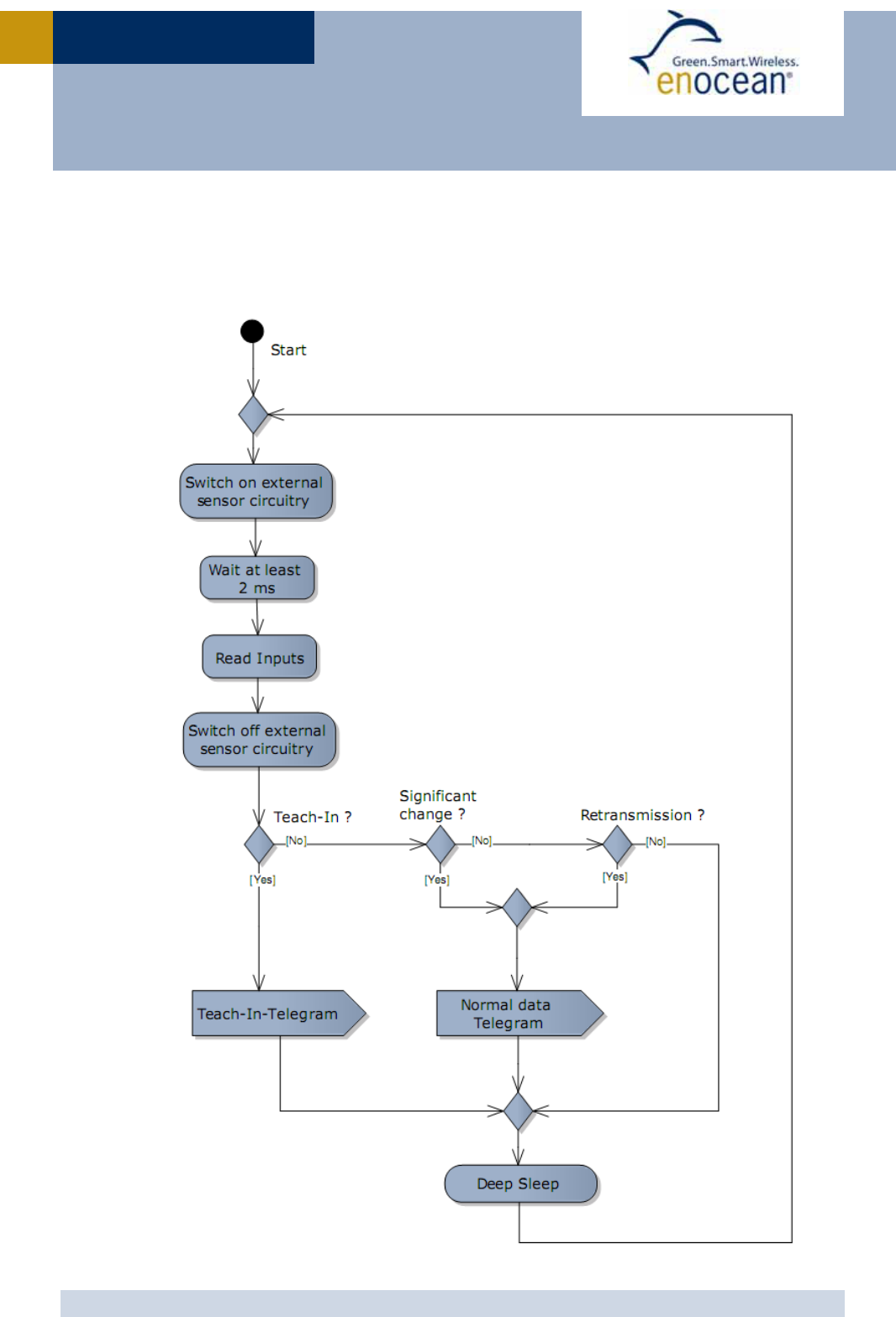
After wake up the external sensors are supplied and
after a configurable delay (default 2ms) the internal microcontroller reads the status of the
connected sensors. A radio telegram will be transmitted in case of a change of any digital
input value compared to the last sending or in case of a significant change of measured
analogue values.
In case of no relevant input change a redundant retransmission signal is sent after a user
configurable number of wake-ups to announce all current values. In addition to the cyclic
wake-up, a wake up can be triggered externally using a wake input or the internal LRN but-
ton.
Features with built-in firmware
Pre-installed solar cell (except STM 312/STM 312C)
On-board energy storage and charging circuit
On-board LRN button
On-board TX indicator LED
20 pin connector for external sensors
3 A/D converter inputs
3 digital inputs
Configurable wake-up and transmission cycle
Wake-up via Wake pins or LRN button
Product variants
STM 310/310C: Variant including solar cell and whip antenna
STM 311/311C: Variant including solar cell and helical antenna
STM 312/312C: Variant including whip antenna but no pre-installed solar cell
Features accessible via API
Using the Dolphin API library it is possible to write custom firmware for the module.
The API provides:
Integrated 16 MHz 8051 CPU with 32 KB FLASH and 2 kB SRAM
Various power down and sleep modes down to typ. 0.2 µA current consumption
Up to 13 configurable I/Os
10 bit ADC, 8 bit DAC

USER MANUA
L
V0.6
© 2010 EnOcean | www.enocean.com STM 31x / STM 31xC User Manual V0.6 | Page 5
/
28
STM 31X / STM 31XC
1.2 Technical data
Antenna whip or helical antenna installed
Frequency 315.0 MHz (STM 31xC)/868.3 MHz (STM 31x)
Radio Standard EnOcean 868 MHz/315 MHz
Data rate/Modulation type 125 kbps/ASK
Conducted Output Power typ. 2 dBm
Power Supply @ VDD Pre-installed solar cell (except STM312 / STM312C)
Illumination 50-100000 lux
2.1 V–5.0 V, 2.6 V needed for start-up
Initial operation time in darkness @
25°C typ. 4 days, energy storage fully charged, wake-up every
100 s, transmission of telegram every 1000 s on average1
Operation start up time with empty
energy store typ. 2.5 min @ 400 lux / 25°C
incandescent or fluorescent light
Input Channels 3x digital input, 2x WAKE input , 3x analog input
Resolution: 3x 8 bit or 1x 10 bit, 1x 8 bit, 1x 6 bit
Radio Regulations R&TTE EN 300 220 (STM 31x)
FCC CFR-47 Part 15 (STM 31xC)
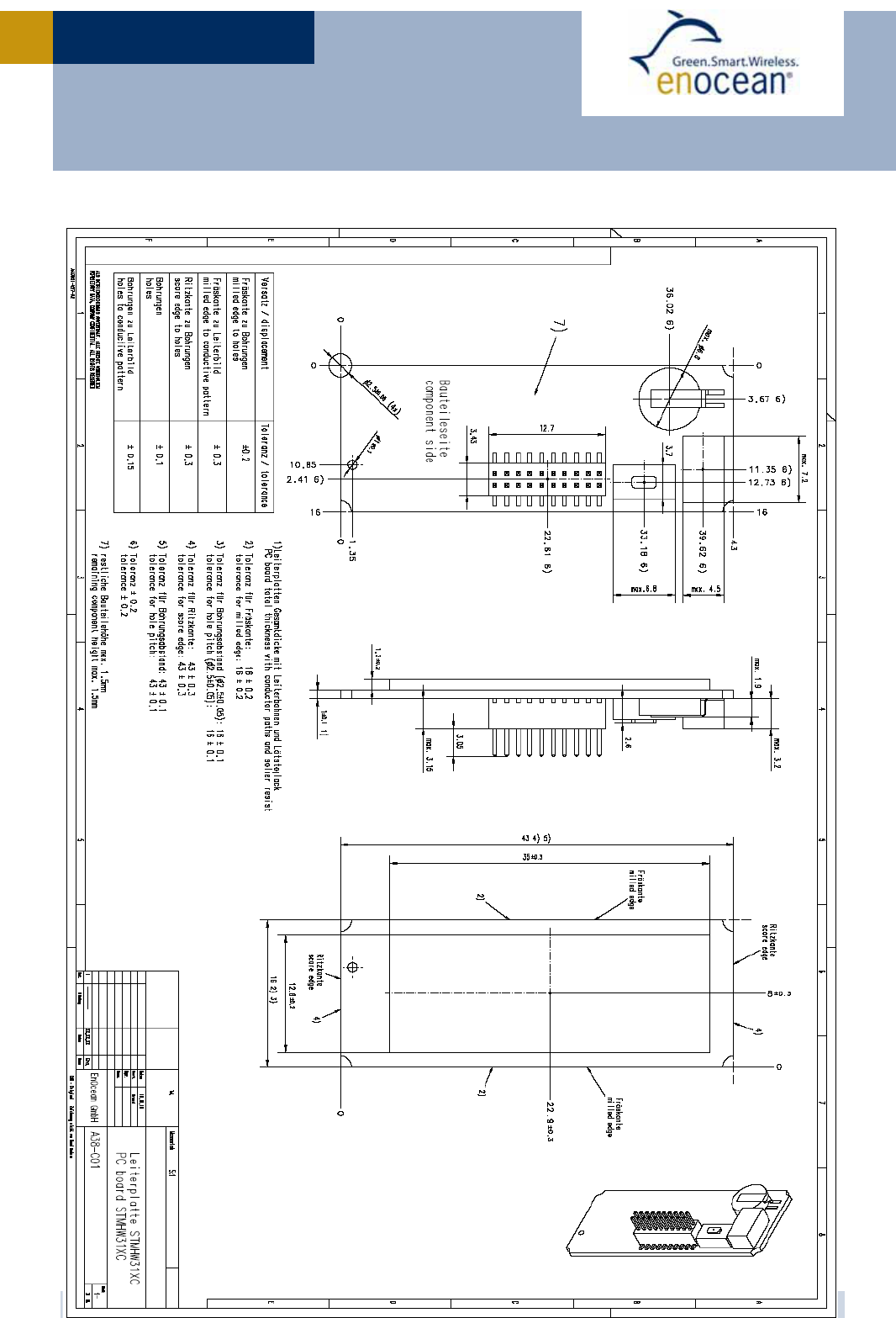
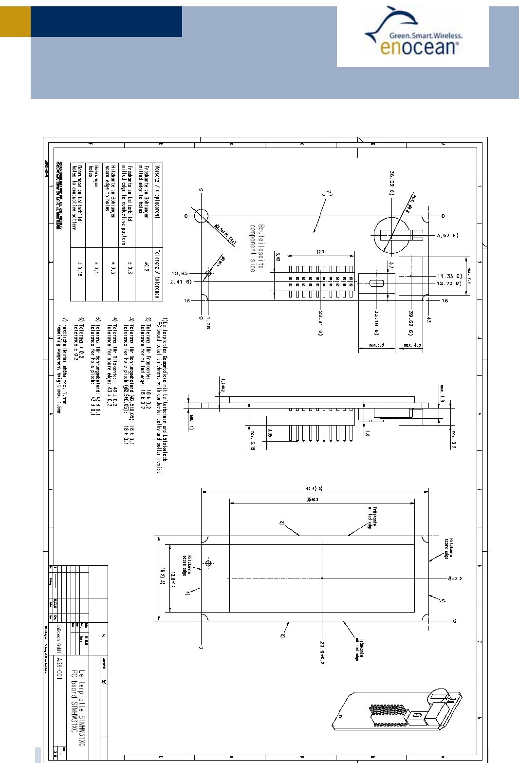
1.3 Physical dimensions
1 Full performance of the PAS614L energy storage is achieved after a few days of operation
at good illumination level. Performance degrades over life time, especially if energy storage
is exposed to higher temperatures. Each 10K drop in temperature doubles the expected life
span.
PCB dimensions 43±0.2 x 16±0.3 x 1±0.1 mm
Module height 9 mm
Weight 3.3g (STM 312) – 6.2g (STM 311C), depending on variant
USER MANUA
L
V0.6
© 2010 EnOcean | www.enocean.com STM 31x / STM 31xC User Manual V0.6 | Page 6
/
28
STM 31X / STM 31XC

USER MANUA
L
V0.6
© 2010 EnOcean | www.enocean.com STM 31x / STM 31xC User Manual V0.6 | Page 7
/
28
STM 31X / STM 31XC
1.4 Environmental conditions
Operating temperature -20 °C … +60 °C
Storage temperature -20 °C … +60 °C
Humidity 0% … 93% r.h., non-condensing
1.5 Ordering Information
Type Ordering Code Frequency
STM 310 S3001-D310 868.3 MHz
STM 311 S3001-D311 868.3 MHz
STM 312 S3001-D312 868.3 MHz
STM 310C S3031-D310 315.0 MHz
STM 311C S3031-D311 315.0 MHz
STM 312C S3031-D312 315.0 MHz
USER MANUA
L
V0.6
© 2010 EnOcean | www.enocean.com STM 31x / STM 31xC User Manual V0.6 | Page 8
/
28
STM 31X / STM 31XC
2 FUNCTIONAL DESCRIPTION
2.1 Simplified firmware flow chart and block diagram
USER MANUA
L
V0.6
© 2010 EnOcean | www.enocean.com STM 31x / STM 31xC User Manual V0.6 | Page 9
/
28
STM 31X / STM 31XC
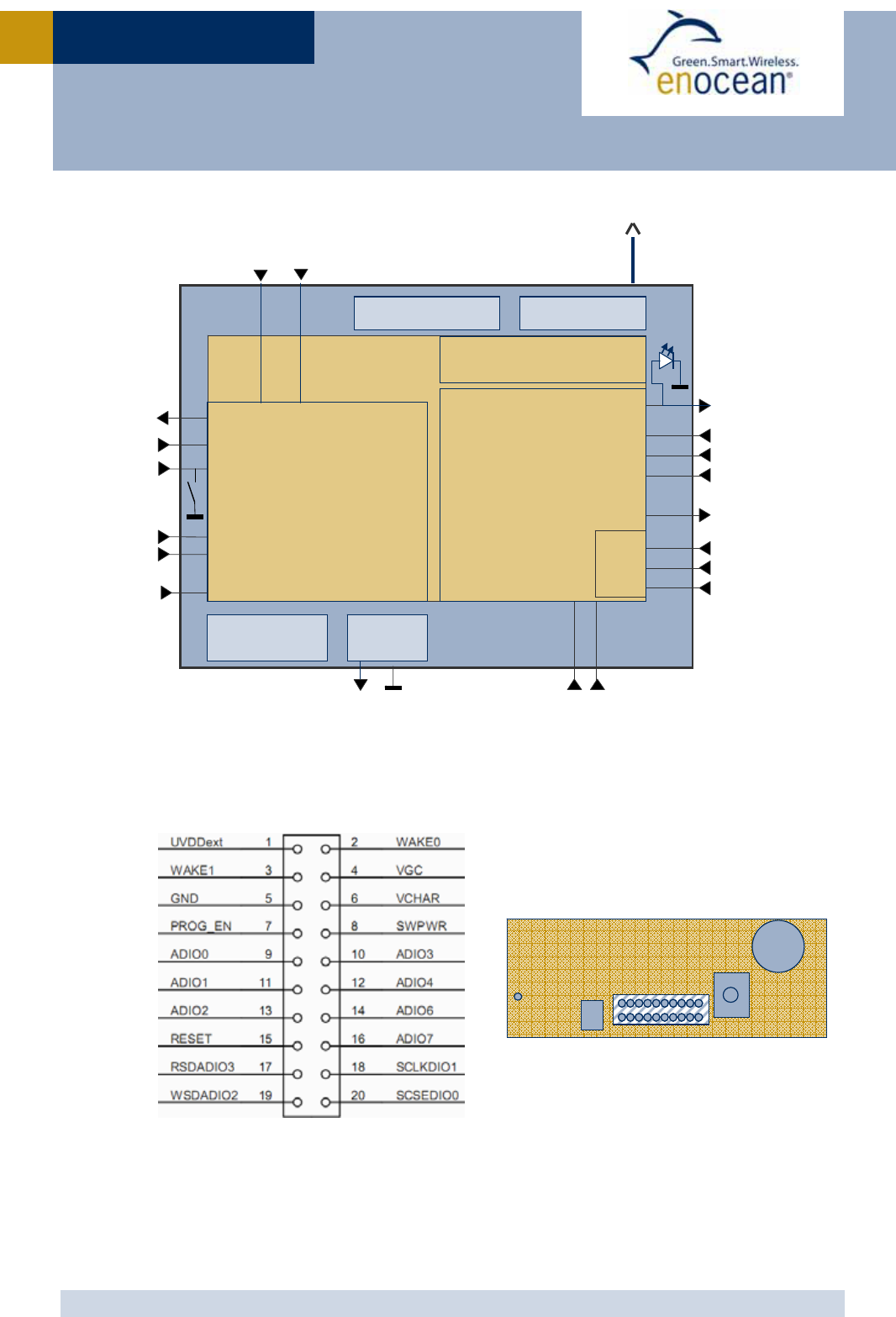
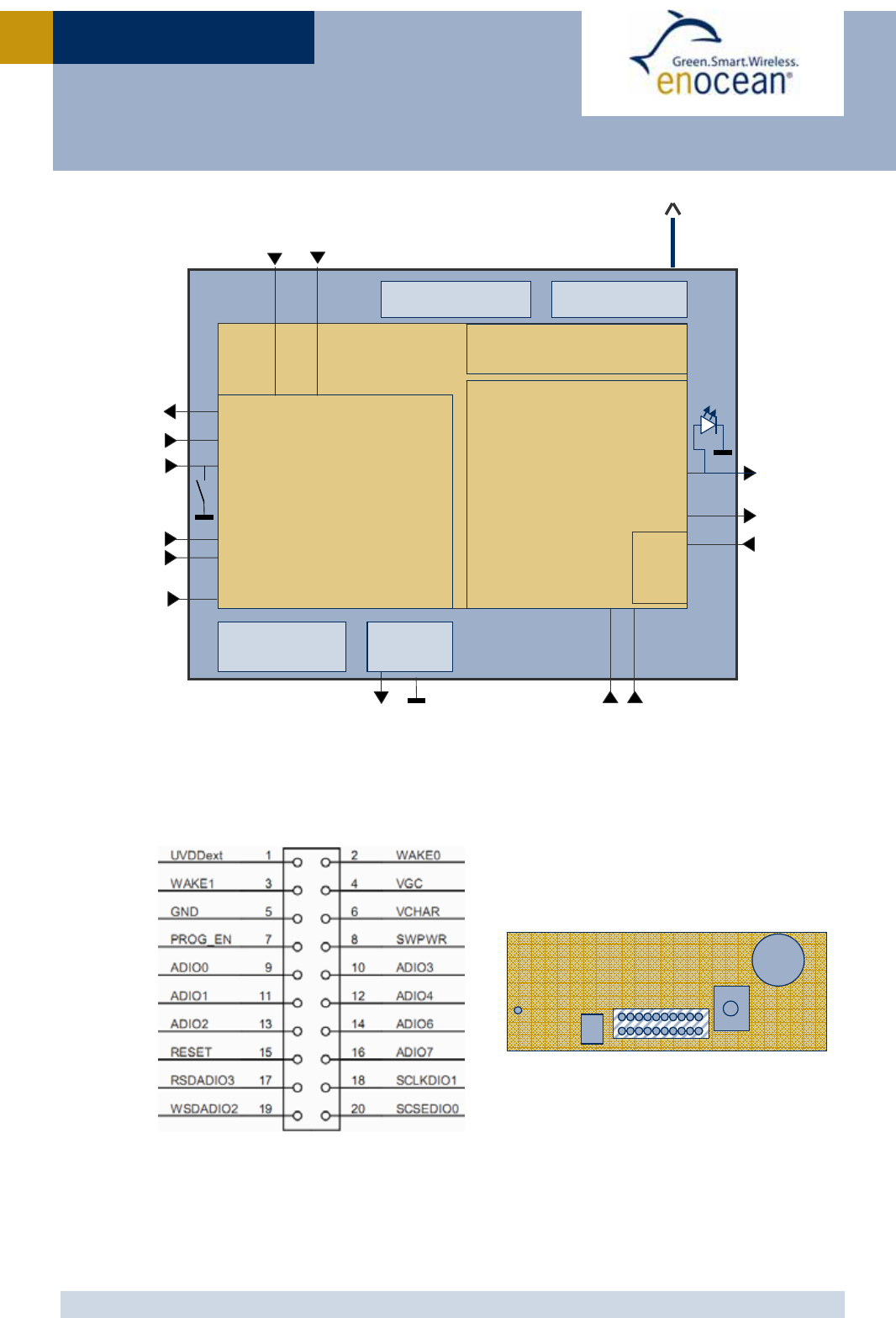
2.2 Pin out
The figure above shows the pin out of the STM 31x hardware. The pins are named accord-
ing to the naming of the EO3000I chip to simplify usage of the DOLPHIN API.
The table in section 2.3 shows the translation of hardware pins to a naming that fits the
functionality of the built-in firmware.
Energy
Store
LR N
LED
1
GND
CW_1
CW_0
WAKE0
CP_1CP_0
LED
LRN
VDD Whip or
helical antenna
UVDDext
RESET
BALUN
Presence Signal
(every 100th,
every 10th,
every cyclic wake-up
or SW defined)
Spontaneous
wake-up
Cyclic Wake-up
(every 1s ,10s , 100s,
or SW defined)
A/D
Power management Micro
Controller
RF Transmitter
868.3 MHz (STM31x)
315.0 MHz (STM31xC)
DOLPHIN
EO3000I
16MHz Oscillator
SWPWR
Energy
Storage
VCHAR
VGC
Solar Cell
LRN button
Transmit
Indicator
AD_2
AD_1
AD_0
DI_2
DI_1
DI_0

USER MANUA
L
V0.6
© 2010 EnOcean | www.enocean.com STM 31x / STM 31xC User Manual V0.6 | Page 10
/
28
STM 31X / STM 31XC
2.3 Pin description and operational characteristics
STM 31x
H a rd w a re
Sym bol
STM 31x
Firm w a re
Sym bol
Function C haracteristics
GND GND Ground connection
VDD VDD Supply voltage 2.1 V – 5.0 V; Start-up voltage: 2.6 V
Maximum ripple: see 2.6
Connection of external 3 V battery possible
VCHAR VCHAR Charging input Input for external energy harvester (for
use in STM 312). See 2.10.
VGC VGC Voltage Gold Cap Connection of additional external energy
storage or battery possible. See 2.10.
SWPWR
(= switched
DVDD)
SWPWR
DVDD supply volt-
age regulator out-
put switched via
transistor con-
trolled by EO3000I
WXIDIO pin.
1.8 V. Output current: max. 5 mA.
Supply for external circuitry, available
while not in deep sleep mode. SWPWR is
switched on 2ms (default) before sampling
of inputs and is switched off afterwards.
The delay time can be configured, see
2.7.2 (needed for stabilization of sensors)
UVDDext
(=UVDD
with 1.8MΩ
in series)
UVDD
Ultra low power
supply voltage
regulator output
Not for supply of external circuitry!
For use with WAKE pins only, see section
3.1. Limited to max. 1 µA output current
by internal 1.8 MΩ resistor!
IOVDD (not
available at
pin connec-
tor)
IOVDD
Digital interface
supply voltage
Internal connection to EO3000I DVDD
(typ. 1.8 V)
See 2.3.1.
RESET
RESET
Reset input
Programming I/F
Active high reset (1.8 V)
Fixed internal 10 kΩ pull-down.
PROG_EN
PROG_EN
Programming I/F HIGH: programming mode active
LOW: operating mode
Digital input, fixed internal 10 kΩ pull-
down.
ADIO0
AD_0
Analog input Input read ~2 ms after wake-up.
Resolution 8 bit. See also 2.7.2.
ADIO1 AD_1 Analog input Input read ~2 ms after wake-up.
Resolution 8 bit (default) or 10 bit.
See 2.7.2.
ADIO2 AD_2 Analog input Input read ~2 ms after wake-up.
Resolution 8 bit (default) or 6 bit.
See 2.7.2.
ADIO3 DI_0 Digital input Input read ~2 ms after wake-up.
See 2.7.2.
Internal pull-up
ADIO4
DI_1
Digital input Input read ~2 ms after wake-up.
See 2.7.2.
Internal pull-up

USER MANUA
L
V0.6
© 2010 EnOcean | www.enocean.com STM 31x / STM 31xC User Manual V0.6 | Page 11
/
28
STM 31X / STM 31XC
ADIO6 DI_2 Digital input Input read ~2 ms after wake-up.
See 2.7.2.
Internal pull-up
LED Transmission
indicator LED
Flashes during radio transmission.
Active LOW.
ADIO7
Programming I/F
CW_1
Encoding input for
wake-up cycle
Configuration interface.
Leave open or connect to GND. See 2.7.1.
Internal pull-up
SCSEDIO0
Programming I/F
CW_0 Encoding input for
wake-up cycle
Configuration interface.
Leave open or connect to GND. See 2.7.1.
Internal pull-up
SCLKDIO1
Programming I/F
CP_1 Encoding input for
retransmission
Configuration interface.
Leave open or connect to GND. See 2.7.1.
Internal pull-up
WSDADIO2
Programming I/F
CP_0 Encoding input for
retransmission
Configuration interface.
Leave open or connect to GND. See 2.7.1.
Internal pull-up
RSDADIO3
Programming I/F
WAKE0 WAKE0 Wake input Change of logic state leads to wake-up and
transmission of a telegram.
Must be connected to UVDDext or GND!
At time of delivery WAKE0 is connected to
UVDDext via a jumper at the connector.
See also 3.1.
WAKE1 LRN LRN input Change of logic state to LOW leads to
wake-up and transmission of teach-in tele-
gram.
Internal pull-up to UVDD.
See also 2.7.2, 2.8.2, and 3.1.
2.3.1 Interface supply voltage
The IOVDD pin of EO3000I is internally connected to DVDD. For digital communication with
other circuitry therefore a voltage of 1.8 V has to be used. While the module is in deep
sleep mode the microcontroller with all its peripherals is switched off and DVDD, IOVDD,
and SWPWR are not supplied.
If DVDD=0 V and IOVDD is not supplied (e.g. while in sleep mode), do not apply
voltage to ADIO0 to ADIO7 and the pins of the serial interface (SCSEDIO0,
SCLKDIO1, WSDADIO2, RSDADIO3). This may lead to unpredictable malfunction
of the device.
For I/O pins configured as analog pins the IOVDD voltage level is not relevant! See
also 2.3.2.

USER MANUA
L
V0.6
© 2010 EnOcean | www.enocean.com STM 31x / STM 31xC User Manual V0.6 | Page 12
/
28
STM 31X / STM 31XC
2.3.2 Analog and digital inputs
Parameter Conditions / Notes Min Typ Max Units
Analog Input
Measurement range
Single ended 0.05 RVDD-
0.05
V
Input coupling DC
Measurement bandwidth 100 kHz
Input resistance
Single ended against
RGND @ 1 kHz
10 MΩ
Input capacitance
Single ended against
RGND @ 1 kHz
10 pF
Effective measurement resolution Configurable, see 2.7.2 6 10 bit
Relative measurement accuracy
Related to the reference
voltage within specified
input range
0.6 %
Digital Input Mode
Input HIGH voltage 2/3
IOVDD
V
Input LOW voltage 1/3
IOVDD
V
Pull up resistor @IOVDD=1.7 … 1.9 V 90 132 200 kΩ
2.4 Absolute maximum ratings (non operating)
Symbol Parameter Min Max Units
VDD Supply voltage at VDD -0.5 5.5 V
VGC Voltage gold cap 1.5 3.3 V
VCHAR Supply voltage from external energy harvester 0 6 V
GND Ground connection 0 0 V
VINA Voltage at every analog input pin -0.5 2 V
VIND Voltage at RESET, WAKE0/1, and every digital input -0.5 3.6 V
2.5 Maximum ratings (operating)
Symbol Parameter Min Max Units
VDD Supply voltage at VDD and VDDLIM 2.1 5.0 V
VGC Voltage gold cap 1.5 3.3 V
VCHAR Supply voltage from external energy harvester 0 6 V
ICHAR
Supply current from external energy harvester
Continuous
Short term (<10 min)
50
1
µA
mA
GND Ground connection 0 0 V
VINA Voltage at every analog input pin 0 2.0 V
VIND Voltage at RESET, WAKE0/1, and every digital input 0 3.6 V

USER MANUA
L
V0.6
© 2010 EnOcean | www.enocean.com STM 31x / STM 31xC User Manual V0.6 | Page 13
/
28
STM 31X / STM 31XC
2.6 Power management and voltage regulators
Symbol Parameter Conditions / Notes Min Typ Max Units
Voltage Regulators
VDDR Ripple on VDD, where
Min(VDD) > VON
50 mVpp
UVDD Ultra Low Power supply 1.8 V
RVDD RF supply Internal signal only 1.7 1.8 1.9 V
DVDD Digital supply Internal signal only 1.7 1.8 1.9 V
Threshold Detector
VON Turn on threshold 2.3 2.45 2.6 V
VOFF Turn off threshold Automatic shutdown if
VDD drops below VOFF
1.85 1.9 2.1 V
Threshold detector
STM 31x provides an internal ultra low power ON/OFF threshold detector. If VDD > VON, it
turns on the ultra low power regulator (UVDD), the watchdog timer and the WAKE# pins
circuitry. If VDD ≤ VOFF it initiates the automatic shut down of STM 31x. For details of this
mechanism please refer to the Dolphin Core Description documentation.
2.7 Configuration
2.7.1 Configuration via pins
The encoding input pins have to be left open or connected to GND in correspondence with
the following connection schemes. These settings are checked at every wake-up.
Wake-up cycle time
CW_0 CW_1 Wake-up cycle time
NC GND 1 s ±20%
GND NC 10 s ±20%
NC NC 100 s ±20%
GND GND No cyclic wake-up
USER MANUA
L
V0.6
© 2010 EnOcean | www.enocean.com STM 31x / STM 31xC User Manual V0.6 | Page 14
/
28
STM 31X / STM 31XC
Redundant retransmission
Via CP_0 and CP_1 an internal counter is set which is decreased at every wake-up signal.
Once the counter reaches zero the redundant retransmission signal is sent.
CP_0 CP_1 Number of wake-ups that
trigger a redundant retransmission
GND NC Every timer wake-up signal
NC NC Every 7th - 14th timer wake-up signal, affected at random
NC GND Every 70th - 140th timer wake-up signal, affected at random
GND GND No redundant retransmission
A radio telegram is always transmitted after wake-up via WAKE pins!
After transmission the counter is reset to a random value within the specified in-
terval.
According to FCC 15.231a) a redundant retransmission at every timer wake-up to
determine the system integrity is only allowed in safety and security applications!
In this case the total transmission time must not exceed two seconds per hour,
which means that a combination with a 1 s wake-up cycle time is not allowed!
If applied in other (non-safety, non-security) applications a minimum of 10 s be-
tween periodic transmissions is required. In addition the device has to comply with
the lower field strength limits of 15.231e). The limited modular approval of STM
31xC is not valid in this case.

USER MANUA
L
V0.6
© 2010 EnOcean | www.enocean.com STM 31x / STM 31xC User Manual V0.6 | Page 15
/
28
STM 31X / STM 31XC
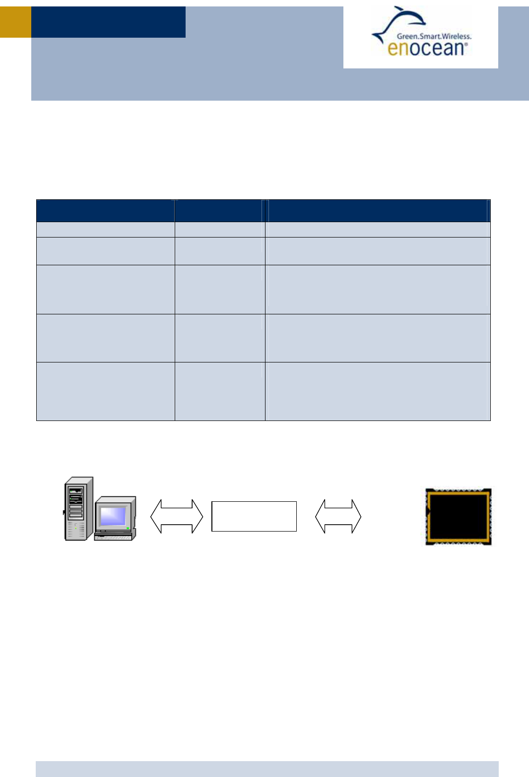
2.7.2 Configuration via serial interface
Via the programming interface the configuration area can be modified. This provides a lot
more configuration options. Values set via serial interface override hardware settings!
These settings are read after RESET or power-on reset only and not at every wake-up of
the module!
The interface is shown in the figure below:
Parameter Configuration
via pins Configuration
via serial interface
Wake up cycle See section 2.7.1 Value can be set from 1 s to 65534 s
Redundant
Retransmission cycle
See section 2.7.1 Min…Max values for random interval
If Min=Max -> random switched off
Threshold values for
analog inputs
(transmission of telegram if
threshold value exceeded)
No The default values are: 5 LSB at AD_1 input, 6
LSB at AD_0 and 14 LSB at AD_2.
The threshold value can be set between 0 and
full scale for every input individually.
Resolution of the analog
inputs
No Default: AD_0: 8 bit, AD_1: 8 bit, AD_2: 8 bit
Option: AD_0: 10 bit, AD_1: 6 bit, AD_2: 8 bit
Input mask No A digital input mask for ignoring changes on
digital input pins. At default all input bits are
checked.
Delay time between SWPWR
on and sampling moment
(for stabilization of external sensor
measurement values)
No Value can be set from 0 ms to 508 ms in steps
of 2 ms. Default delay time is 2 ms.
Source of AD_2 No Select if AD_2 contains measurement value of
external ADIO2 pin or from internal VDD/4
Edge of wake pin change
causing a telegram trans-
mission
No Every change of a wake pin triggers a wake-up.
For both wake pins it can be configured indi-
vidually if a telegram shall be sent on rising,
falling or both edges.
Manufacturer ID and EEP
(EnOcean Equipment Profile)
No Information about manufacturer and type of
device. This feature is needed for “automatic”
interoperability of sensors and actuators or bus
systems. Unique manufacturer IDs are distrib-
uted by the EnOcean Alliance.
USB <=> SPI
interface SPI
USB
Dolphin Studio, or EOP
Reset
PROG_EN
ADIO7
SCSEDIO0
SCLKDIO1
WSDADIO2
RSDADIO3
STM
31
x
VDD
GND
USER MANUA
L
V0.6
© 2010 EnOcean | www.enocean.com STM 31x / STM 31xC User Manual V0.6 | Page 16
/
28
STM 31X / STM 31XC
EnOcean provides EOPx (EnOcean Programmer, a command line program) and Dolphin Stu-
dio (Windows application for chip configuration, programming, and testing) and the
USB/SPI programmer device as part of the EDK 300 developer´s kit.
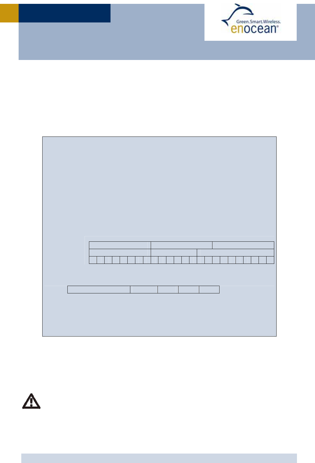
2.8 Radio telegram
2.8.1 Normal operation
Telegram content (seen at serial interface of RCM 130/TCM 3x0 or at DOLPHIN API):
ORG = 0x07 (Telegram type “4BS”)
Data_Byte1..3
3x8bit mode:
DATA_BYTE3 = Value of AD_2 analog input
DATA_BYTE2 = Value of AD_1 analog input
DATA_BYTE1 = Value of AD_0 analog input
1x8bit, 1x6it, 1x10bit mode:
DATA_BYTE3 = Value of AD_2
DATA_BYTE2 = Upper 2 bits of AD_0 and value of AD_1
DATA_BYTE1 = Lower 8 bits Value of AD_0 analog input
DATA_BYTE0 = Digital sensor inputs as follows:
Bit 7 Bit 0
Reserved, set to 0 DI_3=1 DI_2 DI_1 DI_0
ID_BYTE3 = module identifier (Byte3)
ID_BYTE2 = module identifier (Byte2)
ID_BYTE1 = module identifier (Byte1)
ID_BYTE0 = module identifier (Byte0)
DATA_BYTE3 DATA_BYTE2 DATA_BYTE1
AD_2 AD_1 AD_0
7 6 5 4 3 2 1 0 5 4 3 2 1 0 9 8 7 6 5 4 3 2 1 0
The voltages measured at the analog inputs can be calculated from these values as follows:
U=(Value of AD_x)/(2n)x1.8 V n=resolution of channel in bit
Please note the limitations in the measurement range of the A/D converter as
shown in 2.3.2.
USER MANUA
L
V0.6
© 2010 EnOcean | www.enocean.com STM 31x / STM 31xC User Manual V0.6 | Page 17
/
28
STM 31X / STM 31XC
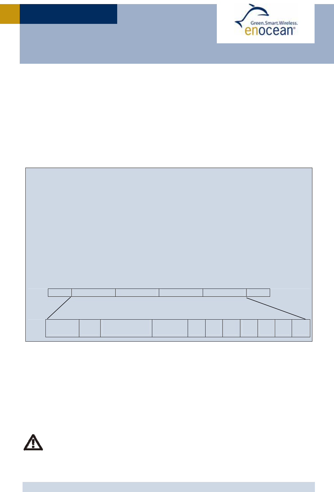
2.8.2 Teach-in telegram
In case of a wake-up via WAKE1 pin (LRN input) the module transmits a teach-in telegram.
If the manufacturer code is not set, the module transmits a normal telegram according to 2.8.1
with the difference that DI_3=0.
If a manufacturer code is set, this teach-in telegram contains special information as described
below.
With this special teach-in telegram it is possible to identify the manufacturer of a device
and the function and type of a device. There is a list available from the EnOcean Alliance
describing the functionalities of the respective products.
ORG = 0x07 (Telegram type “4BS”)
DATA_BYTE0..3 see below
LRN Type = 1
LRN = 0
DI0..DI2: current status of digital inputs
Profile, Type, Manufacturer-ID defined by manufacturer
RE0..2: set to 0
ID_BYTE3 = module identifier (Byte3)
ID_BYTE2 = module identifier (Byte2)
ID_BYTE1 = module identifier (Byte1)
ID_BYTE0 = module identifier (Byte0)
ORG Data_Byte3 Data_Byte2 Data_Byte1 Data_Byte0 ID
Function
6 Bit
Type
7 Bit
Manufacturer-
ID 11 Bit
LRN Type
1Bit
RE2
1Bit
RE1
1Bit
RE0
1Bit
LRN
1Bit
DI2
1Bit
DI1
1Bit
DI0
1Bit
2.9 Transmit timing
The setup of the transmission timing allows avoiding possible collisions with data packages
of other EnOcean transmitters as well as disturbances from the environment. With each
transmission cycle, 3 identical subtelegrams are transmitted within 40 ms. The transmis-
sion of a subtelegram lasts approximately 1.2 ms. The delay between the three transmis-
sion bursts is affected at random.
If a new wake-up occurs before all sub-telegrams have been sent, the series of
transmissions is stopped and a new series of telegrams with new valid measure-
ment values is transmitted.
USER MANUA
L
V0.6
© 2010 EnOcean | www.enocean.com STM 31x / STM 31xC User Manual V0.6 | Page 18
/
28
STM 31X / STM 31XC
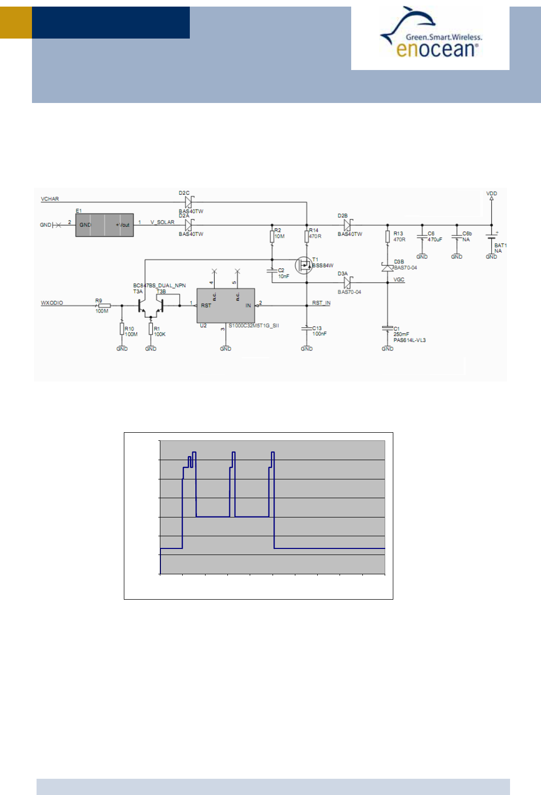
2.10 Charging circuitry
The figure below shows the internal charging circuit. It is controlled via the WXODIO pin of
EO3000I which switches according to the status of the internal threshold detector. For de-
tails please refer to our Dolphin Core Description documentation.
An external 3 V battery can be connected at VDD (STM 312 only) or at VGC.
2.11 Energy consumption
Current Consumption of STM 31x
Charge needed for one measurement and transmit cycle: ~130 µC
Charge needed for one measurement cycle without transmit: ~30 µC
(current for external sensor circuits not included)
Calculations are performed on the basis of electric charges because of the internal linear
voltage regulator of the module. Energy consumption varies with voltage of the energy
storage while consumption of electric charge is constant.
0.00001
0.0001
0.001
0.01
0.1
1
10
100
0 102030405060708090100
Time [ms]
C u rre n t [mA]

USER MANUA
L
V0.6
© 2010 EnOcean | www.enocean.com STM 31x / STM 31xC User Manual V0.6 | Page 19
/
28
STM 31X / STM 31XC
From these values the following performance parameters have been calculated:
Wake
cycle
[s] Transmit
interval
Operation Time
in darkness [h]
when storage
fully charged
Required reload
time [h] at 200
lux within 24 h
for continuous
operation
24 h operation
after 6 h
illumination
at x lux
Illumina-
tion level
in lux for
continuous
operation
Current
in µA
required
for con-
tinuous
operation
1 1 0.5 storage too sm all storage too sm all 5220 130.5
1 10 1.7 storage too sm all storage too sm all 1620 40.5
1 100 2.1 storage too sm all storage too sm all 1250 31.3
10 1 5.1 storage too sm all storage too sm all 540 13.5
10 10 16 21 700 175 4.4
10 100 20 16.8 560 140 3.5
100 1 43 7.8 260 65 1.6
100 10 98 3.6 120 30 0.8
100 100 112 3 100 25 0.6
Assumptions:
Internal storage PAS614L-VL3 with 0.25 F, Umax=3.2 V, Umin=2.2 V, T=25 °C
Consumption: Transmit cycle 100 µC, measurement cycle 30 µC
Pre-installed solar cell ECS 300, operating values 3 V and 5 µA @ 200 lux fluorescent
light
Current proportional to illumination level (not true at very low levels!)
These values are calculated values, the accuracy is about +/-20%!

USER MANUA
L
V0.6
© 2010 EnOcean | www.enocean.com STM 31x / STM 31xC User Manual V0.6 | Page 20
/
28
STM 31X / STM 31XC
3 APPLICATIONS INFORMATION
3.1 Using the WAKE pins
The logic input circuits of the WAKE0 and WAKE1 pins are supplied by UVDD and therefore
also usable in “Deep Sleep Mode”. Due to current minimization there is no internal pull-up
or pull-down at the WAKE pins. When STM 31x is in “Deep Sleep Mode” and the logic levels
of WAKE0 and / or WAKE1 is changed, STM 31x starts up.
As the there is no internal pull-up or pull-down at the WAKE0 pin, it has to be en-
sured by external circuitry, that the WAKE0 pin is at a defined logic level at any
time. At time of delivery a jumper is connected between WAKE0 and UVDDext.
WAKE1 provides an internal 1.8 MΩ pull-up. See figure below.
When the LRN button is pressed WAKE1 is pulled to GND and a teach-in telegram is trans-
mitted. As long as the button is pressed a small current of approximately 1 µA is flowing. It
is possible to connect an additional external button in parallel between WAKE1 and GND if a
different position of the button in the device is required.
WAKE0 is connected to UVDDext via a jumper at time of delivery. If the module is mounted
onto a host PCB the jumper has to be removed. The circuitry on the host PCB then has to
ensure that WAKE0 is always in a defined position. There are two ways to use WAKE0:
Connect WAKE0 to UVDDext and connect an external button between WAKE0 and GND.
As long as the button is pressed a current of 1 µA will flow.
Connect a 3 terminal switch and switch WAKE0 to either GND or UVDDext. In this case
there is no continuous flow of current in either position of the switch.
EO3000I
WAKE0
WAKE1
UVDD
UVDDext
STM 31x
WAKE1
WAKE0
GND
1M8
1M8
LRN Button
Jumper installed at
time of delivery
USER MANUA
L
V0.6
© 2010 EnOcean | www.enocean.com STM 31x / STM 31xC User Manual V0.6 | Page 21
/
28
STM 31X / STM 31XC
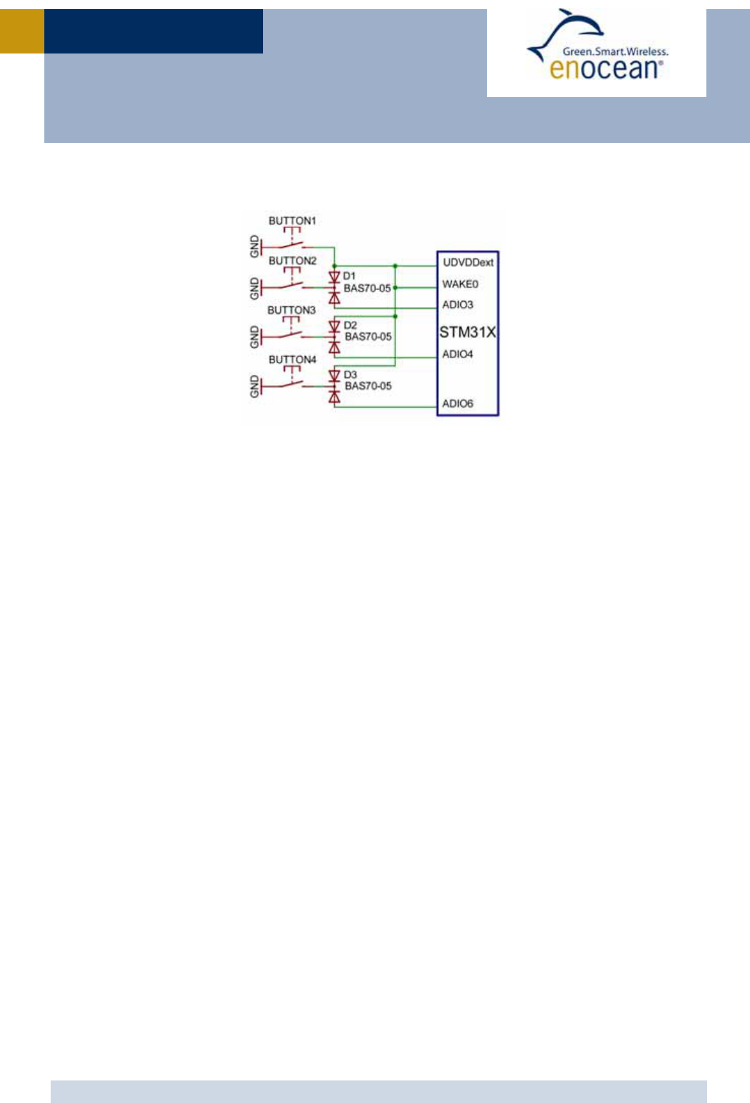
If more digital inputs with WAKE functionality are needed in an application, WAKE0 can be
combined with some of the digital inputs as shown below:
USER MANUA
L
V0.6
© 2010 EnOcean | www.enocean.com STM 31x / STM 31xC User Manual V0.6 | Page 22
/
28
STM 31X / STM 31XC
3.2 Antenna options
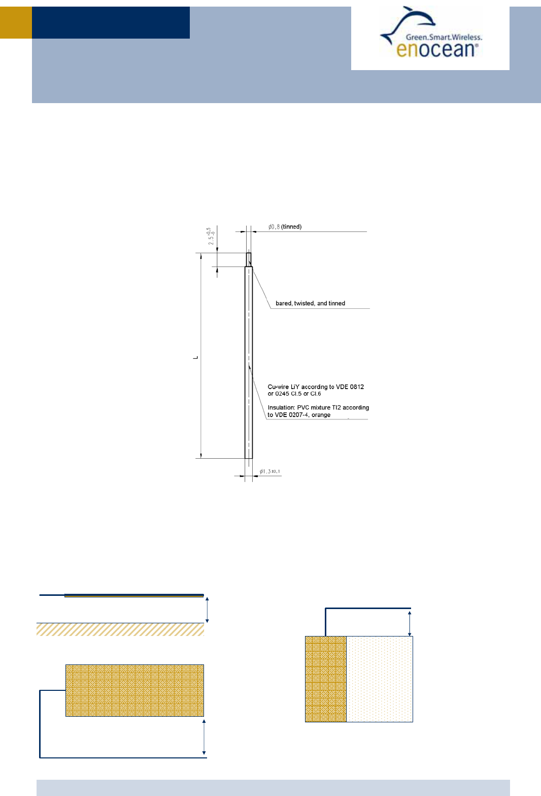
3.2.1 Whip antenna (STM 310, STM 310C, STM 312, STM 312C)
Specification of the whip antenna; L=150 mm @ 315 MHz, L=86 mm @ 868 MHz
Antenna layout recommendation:
STM 31x without host PCB STM 31x with host PCB
Glass, wood, concrete, metal
868MHz: > 2cm
315MHz: > 4cm
868MHz: > 1cm
315MHz: > 2cm
868MHz: > 2cm
315MHz: > 4cm
Host PCB
GND plane
USER MANUA
L
V0.6
© 2010 EnOcean | www.enocean.com STM 31x / STM 31xC User Manual V0.6 | Page 23
/
28
STM 31X / STM 31XC
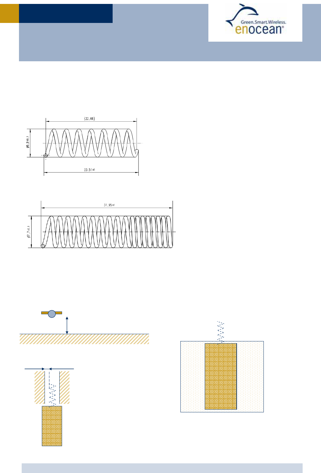
3.2.2 Helical antenna (STM 311, STM 311C)
868 MHz
315 MHz
Antenna recommendation:
STM 31x without host PCB STM 31x with host PCB
Glass, wood, concrete, metal
868MHz: > 2mm
315MHz: > 4mm
868MHz: > 5mm
315MHz: > 10mm
Plastic
Host PCB
GND plane

USER MANUA
L
V0.6
© 2010 EnOcean | www.enocean.com STM 31x / STM 31xC User Manual V0.6 | Page 24
/
28
STM 31X / STM 31XC
3.3 Transmission range
The main factors that influence the system transmission range are type and location of the
antennas of the receiver and the transmitter, type of terrain and degree of obstruction of
the link path, sources of interference affecting the receiver, and “Dead” spots caused by
signal reflections from nearby conductive objects. Since the expected transmission range
strongly depends on this system conditions, range tests should categorically be performed
before notification of a particular range that will be attainable by a certain application.
The following figures for expected transmission range are considered by using a PTM, a
STM or a TCM radio transmitter device and the TCM radio receiver device with preinstalled
whip antenna and may be used as a rough guide only:
Line-of-sight connections: Typically 30 m range in corridors, up to 100 m in halls
Plasterboard walls / dry wood: Typically 30 m range, through max. 5 walls
Line-of-sight connections: Typically 30 m range in corridors, up to 100 m in halls
Ferroconcrete walls / ceilings: Typically 10 m range, through max. 1 ceiling
Fire-safety walls, elevator shafts, staircases and supply areas should be considered as
screening.
The angle at which the transmitted signal hits the wall is very important. The effective wall
thickness – and with it the signal attenuation – varies according to this angle. Signals
should be transmitted as directly as possible through the wall. Wall niches should be
avoided. Other factors restricting transmission range:
Switch mounted on metal surfaces (up to 30% loss of transmission range)
Hollow lightweight walls filled with insulating wool on metal foil
False ceilings with panels of metal or carbon fiber
Lead glass or glass with metal coating, steel furniture
The distance between EnOcean receivers and other transmitting devices such as com-
puters, audio and video equipment that also emit high-frequency signals should be at least
0.5 m
A summarized application note to determine the transmission range within buildings is
available as download from www.enocean.com.
USER MANUA
L
V0.6
© 2010 EnOcean | www.enocean.com STM 31x / STM 31xC User Manual V0.6 | Page 25
/
28
STM 31X / STM 31XC
4 AGENCY CERTIFICATIONS
The modules have been tested to fulfil the approval requirements for CE (STM 31x) and
FCC/IC (STM 31xC) based on the built-in firmware.
When developing customer specific firmware based on the API for this module,
special care must be taken not to exceed the specified regulatory limits, e.g. the
duty cycle limitations!
4.1 CE Approval
The STM 31x module bears the EC conformity marking CE and conforms to the R&TTE EU-
directive on radio equipment. The assembly conforms to the European and national re-
quirements of electromagnetic compatibility. The conformity has been proven and the ac-
cording documentation has been deposited at EnOcean. The modules can be operated with-
out notification and free of charge in the area of the European Union and in Switzerland.
EnOcean RF modules must not be modified or used outside their specifica-
tion limits.
EnOcean RF modules may only be used to transfer digital or digitized data.
Analog speech and/or music are not permitted.
EnOcean RF modules must not be used with gain antennas, since this may
result in allowed ERP or spurious emission levels being exceeded.
The final product incorporating EnOcean RF modules must itself meet the
essential requirement of the R&TTE Directive and a CE marking must be af-
fixed on the final product and on the sales packaging each. Operating in-
structions containing a Declaration of Conformity has to be attached.
If the STM 31x transmitter is used according to the regulations of the 868.3
MHz band, a so-called “Duty Cycle” of 1% per hour must not be exceeded.
Permanent transmitters such as radio earphones are not allowed.
The module must be used with only the following approved antenna(s).
Model T
yp
e
STM 310
STM 312
Pre-installed Wire/Monopole
STM 311 Pre-installed helical antenna

USER MANUA
L
V0.6
© 2010 EnOcean | www.enocean.com STM 31x / STM 31xC User Manual V0.6 | Page 26
/
28
STM 31X / STM 31XC
4.2 FCC (United States) certification
STM 31xC LIMITED MODULAR APPROVAL
This is an RF module approved for Limited Modular use operating as an intentional trans-
mitting device with respect to 47 CFR 15.231(a-c) and is limited to OEM installation. The
module is optimized to operate using small amounts of harvested energy, such as can be
collected by a small solar cell exposed to ambient light. The module transmits short radio
packets comprised of control signals, (in some cases the control signal may be accompa-
nied with data) such as those used with alarm systems, door openers, remote switches,
and the like. The module does not support continuous streaming of voice, video, or any
other forms of streaming data; it sends only short packets containing control signals and
possibly data and is typically powered by a solar cell in ambient light. The module is de-
signed to comply with, has been tested according to 15.231(a-c), and has been found to
comply with each requirement. Thus, a finished device containing the STM 31xC radio mod-
ule can be operated in the United States without additional Part 15 FCC approval (ap-
proval(s) for unintentional radiators may be required for the OEM’s finished product), under
EnOcean’s FCC ID number. This greatly simplifies and shortens the design cycle and devel-
opment costs for OEM integrators.
The module can be triggered manually or automatically, which cases are described below.
Manual Activation
The radio module can be configured to transmit a short packetized control signal if
triggered manually. The module can be triggered, by pressing a switch, for example.
The packet contains one (or more) control signals that is(are) intended to control
something at the receiving end. The packet may also contain data. Depending on
how much energy is available from the energy source, subsequent manual triggers
can initiate the transmission of additional control signals. This may be necessary if
prior packet(s) was (were) lost to fading or interference. Subsequent triggers can
also be initiated as a precaution if any doubt exists that the first packet didn’t arrive
at the receiver. Each packet that is transmitted, regardless of whether it was the
first one or a subsequent one, will only be transmitted if enough energy is available
from the energy source.
Automatic Activation
The radio module also can be configured to transmit a short packetized control sig-
nal if triggered automatically, by a relevant change of its inputs, for example. Again,
the packet contains a control signal that is intended to control something at the re-
ceiving end and may also contain data. As above, it is possible for the packet to get
lost and never reach the receiver. However, if enough energy is available from the
energy source, and the module has been configured to do so, then another packet or
packets containing the control signal may be transmitted at a later, unpredictable
time.

USER MANUA
L
V0.6
© 2010 EnOcean | www.enocean.com STM 31x / STM 31xC User Manual V0.6 | Page 27
/
28
STM 31X / STM 31XC
OEM Requirements
In order to use EnOcean’s FCC ID number, the OEM must ensure that the following condi-
tions are met.
End users of products, which contain the module, must not have the ability to alter the
firmware that governs the operation of the module. The agency grant is valid only when
the module is incorporated into a final product by OEM integrators.
The end-user must not be provided with instructions to remove, adjust or install the
module.
The Original Equipment Manufacturer (OEM) must ensure that FCC labeling requirements
are met. This includes a clearly visible label on the outside of the final product. Attaching
a label to a removable portion of the final product, such as a battery cover, is not per-
mitted. The label must include the following text:
STM 310C, STM 312C:
Contains FCC ID: SZV-STM310C
The enclosed device complies with Part 15 of the FCC Rules. Operation is subject to
the following two conditions: (i.) this device may not cause harmful interference and
(ii.) this device must accept any interference received, including interference that
may cause undesired operation.
STM 311C:
Contains FCC ID: SZV-STM311C
The enclosed device complies with Part 15 of the FCC Rules. Operation is subject to
the following two conditions: (i.) this device may not cause harmful interference and
(ii.) this device must accept any interference received, including interference that
may cause undesired operation.
When the device is so small or for such use that it is not practicable to place the state-
ment above on it, the information required by this paragraph shall be placed in a promi-
nent location in the instruction manual or pamphlet supplied to the user or, alterna-
tively, shall be placed on the container in which the device is marketed. However, the
FCC identifier or the unique identifier, as appropriate, must be displayed on the device.
The user manual for the end product must also contain the text given above.
Changes or modifications not expressly approved by EnOcean could void the user's au-
thority to operate the equipment.
The OEM must ensure that timing requirements according to 47 CFR 15.231(a-c) are
met.
The OEM must sign the OEM Limited Modular Approval Agreement with EnOcean
The module must be used with only the following approved antenna(s).

USER MANUA
L
V0.6
© 2010 EnOcean | www.enocean.com STM 31x / STM 31xC User Manual V0.6 | Page 28
/
28
STM 31X / STM 31XC
4.3 IC (Industry Canada) certification
In order to use EnOcean’s IC number, the OEM must ensure that the following conditions
are met:
Labeling requirements for Industry Canada are similar to those required by the FCC. The
Original Equipment Manufacturer (OEM) must ensure that IC labeling requirements are
met. A clearly visible label on the outside of a non-removable part of the final product
must include the following text:
STM 310C, STM 312C:
Contains IC: 5713A-STM310C
STM 311C
Contains IC: 5713A-STM311C
The OEM must sign the OEM Limited Modular Approval Agreement with EnOcean
Model T
yp
eGain
STM 310C
STM 312C
Pre-installed Wire/Monopole 1.0 dBi
STM 311C Pre-installed helical antenna -9 dBi

USER MANUA
L
V0.60
EnOcean GmbH
Kolpingring 18a
82041 Oberhaching
Germany
Phone +49.89.67 34 689-0
Fax +49.89.67 34 689-50
info@enocean.com
www.enocean.com
Subject to modifications
STM 330 / STM 330C User Manual V0.60
September 7, 2010 4:00 PM
Page 1/27
Patent protected:
WO98/36395, DE 100 25 561, DE 101 50 128,
WO 2004/051591, DE 103 01 678 A1, DE 10309334,
WO 04/109236, WO 05/096482, WO 02/095707,
US 6,747,573, US 7,019,241
Observe precautions! Electrostatic sensitive devices!
Scavenger Transmitter Module
STM 330 / STM 330C
September 7, 2010

USER MANUA
L
V0.60
© 2010 EnOcean | www.enocean.com STM 330 / STM 330C User Manual V0.60 | Page 2
/
27
STM 330 / STM 330C
REVISION HISTORY
The following major modifications and improvements have been made to the first version of
this document:
No Major Changes
0.55 Initial version
0.60 New drawings added; Agency certifications added
Published by EnOcean GmbH, Kolpingring 18a, 82041 Oberhaching, Germany
www.enocean.com, info@enocean.com, phone ++49 (89) 6734 6890
© EnOcean GmbH
All Rights Reserved
Important!
This information describes the type of component and shall not be considered as assured characteris-
tics. No responsibility is assumed for possible omissions or inaccuracies. Circuitry and specifications
are subject to change without notice. For the latest product specifications, refer to the EnOcean web-
site: http://www.enocean.com.
As far as patents or other rights of third parties are concerned, liability is only assumed for modules,
not for the described applications, processes and circuits.
EnOcean does not assume responsibility for use of modules described and limits its liability to the
replacement of modules determined to be defective due to workmanship. Devices or systems contain-
ing RF components must meet the essential requirements of the local legal authorities.
The modules must not be used in any relation with equipment that supports, directly or indirectly,
human health or life or with applications that can result in danger for people, animals or real value.
Components of the modules are considered and should be disposed of as hazardous waste. Local
government regulations are to be observed.
Packing: Please use the recycling operators known to you. By agreement we will take packing mate-
rial back if it is sorted. You must bear the costs of transport. For packing material that is returned to
us unsorted or that we are not obliged to accept, we shall have to invoice you for any costs incurred.

USER MANUA
L
V0.60
© 2010 EnOcean | www.enocean.com STM 330 / STM 330C User Manual V0.60 | Page 3
/
27
STM 330 / STM 330C
TABLE OF CONTENT
1 GENERAL DESCRIPTION................................................................................. 4
1.1 Basic functionality ......................................................................................... 4
1.2 Technical data .............................................................................................. 5
1.3 Physical dimensions....................................................................................... 5
1.4 Environmental conditions ............................................................................... 7
1.5 Ordering Information ..................................................................................... 7
2 FUNCTIONAL DESCRIPTION............................................................................ 8
2.1 Simplified firmware flow chart and block diagram.............................................. 8
2.2 Pin out ......................................................................................................... 9
2.3 Pin description and operational characteristics ................................................ 10
2.3.1 Interface supply voltage........................................................................... 11
2.3.2 Analog and digital inputs .......................................................................... 12
2.3.3 Temperature sensor................................................................................. 12
2.4 Absolute maximum ratings (non operating) .................................................... 12
2.5 Maximum ratings (operating)........................................................................ 13
2.6 Power management and voltage regulators .................................................... 13
2.7 Configuration.............................................................................................. 14
2.7.1 Configuration via pins .............................................................................. 14
2.7.2 Configuration via serial interface ............................................................... 15
2.8 Radio telegram ........................................................................................... 17
2.8.1 Normal operation .................................................................................... 17
2.8.2 Teach-in telegram ................................................................................... 17
2.9 Transmit timing .......................................................................................... 17
2.10 Charging circuitry................................................................................... 18
2.11 Energy consumption ............................................................................... 18
3 APPLICATIONS INFORMATION ...................................................................... 20
3.1 Using the WAKE pins ................................................................................... 20
3.2 Temperature sensor .................................................................................... 21
3.3 Set point control and occupancy button.......................................................... 21
3.4 Antenna ..................................................................................................... 22
3.4.1 Whip antenna ......................................................................................... 22
3.5 Transmission range ..................................................................................... 23
4 AGENCY CERTIFICATIONS ............................................................................ 24
4.1 CE Approval................................................................................................ 24
4.2 FCC (United States) certification ................................................................... 25
4.3 IC (Industry Canada) certification.................................................................. 27

USER MANUA
L
V0.60
© 2010 EnOcean | www.enocean.com STM 330 / STM 330C User Manual V0.60 | Page 4
/
27
STM 330 / STM 330C
1 GENERAL DESCRIPTION
1.1 Basic functionality
The extremely power saving RF transmitter mod-
ule STM 330 of EnOcean is optimized for realiza-
tion of wireless and maintenance free temperature
sensors, or room operating panels including set
point dial and occupancy button with a minimum
number of external components. The module pro-
vides an integrated calibrated temperature sensor.
Power supply is provided by a small solar cell, an external energy harvester, or an external
3 V battery. An energy storage is installed to bridge periods with no supply from the energy
harvester. The module provides a user configurable cyclic wake up.
After wake up the internal microcontroller reads the status of the temperature sensor and
optional set point dial. A radio telegram will be transmitted in case of a significant change
of measured temperature or set point values or if the external occupancy button is pressed.
In case of no relevant input change a redundant retransmission signal is sent after a user
configurable number of wake-ups to announce all current values.
In addition to the cyclic wake-up, a wake up can be triggered externally using the input for
the occupancy button or the internal LRN button.
The firmware can be configured to use different EEPs according to the availability set point
dial and occupancy button.
Features with built-in firmware
Pre-installed solar cell
On-board energy storage and charging circuit
On-board LRN button
On-board TX indicator LED
Calibrated internal temperature sensor
Input for external occupancy button and set point dial
Configurable wake-up and transmission cycle
Wake-up via Wake pins or LRN button
Features accessible via API
Using the Dolphin API library it is possible to write custom firmware for the module.
The API provides:
Integrated 16 MHz 8051 CPU with 32 KB FLASH and 2 kB SRAM
Integrated temperature sensor
Various power down and sleep modes down to typ. 0.2 µA current consumption
Up to 13 configurable I/Os
10 bit ADC, 8 bit DAC

USER MANUA
L
V0.60
© 2010 EnOcean | www.enocean.com STM 330 / STM 330C User Manual V0.60 | Page 5
/
27
STM 330 / STM 330C
1.2 Technical data
Antenna Pre-installed whip antenna
Frequency 315.0 MHz (STM 330C)/868.3 MHz (STM 330)
Radio Standard EnOcean 868 MHz/315 MHz
Data rate/Modulation type 125 kbps/ASK
Conducted Output Power typ. 2 dBm
Power Supply @ VDD Pre-installed solar cell
Illumination 50-100000 lux
2.1 V–5.0 V, 2.6 V needed for start-up
Initial operation time in darkness @
25°C typ. 4 days, energy storage fully charged, wake-up every
100 s, transmission of telegram every 1000 s on average1
Operation start up time with empty
energy store typ. 2.5 min @ 400 lux / 25°C
incandescent or fluorescent light
Input Channels Internal: temperature sensor, LRN button
External: occupancy button, set point dial
Temperature sensor Measurement range 0-40°C, resolution 0.15K
Acccuracy typ. ±0.5K between 15°C and 25°C
typ. ±1K between 0°C and 40°C
EnOcean Equipment Profiles configurable EEPs: 07-02-05 (default), 07-10-05, 07-10-03
Connector 20 pin
Radio Regulations R&TTE EN 300 220 (STM 330)
FCC CFR-47 Part 15 (STM 330C)
1.3 Physical dimensions
1 Full performance of the PAS614L energy storage is achieved after a few days of operation
at good illumination level. Performance degrades over life time, especially if energy storage
is exposed to higher temperatures. Each 10K drop in temperature doubles the expected life
span.
PCB dimensions 43±0.2 x 16±0.3 x 1±0.1 mm
Module height 9 mm
Weight 4.5g (STM 330), 4.7g (STM 330C)
USER MANUA
L
V0.60
© 2010 EnOcean | www.enocean.com STM 330 / STM 330C User Manual V0.60 | Page 6
/
27
STM 330 / STM 330C

USER MANUA
L
V0.60
© 2010 EnOcean | www.enocean.com STM 330 / STM 330C User Manual V0.60 | Page 7
/
27
STM 330 / STM 330C
1.4 Environmental conditions
Operating temperature -20 °C … +60 °C
Storage temperature -20 °C … +60 °C
Humidity 0% … 93% r.h., non-condensing
1.5 Ordering Information
Type Ordering Code Frequency
STM 330 S3001-D330 868.3 MHz
STM 330C S3031-D330 315.0 MHz
USER MANUA
L
V0.60
© 2010 EnOcean | www.enocean.com STM 330 / STM 330C User Manual V0.60 | Page 8
/
27
STM 330 / STM 330C
2 FUNCTIONAL DESCRIPTION
2.1 Simplified firmware flow chart and block diagram
USER MANUA
L
V0.60
© 2010 EnOcean | www.enocean.com STM 330 / STM 330C User Manual V0.60 | Page 9
/
27
STM 330 / STM 330C
2.2 Pin out
The figure above shows the pin out of the STM 330 hardware. The pins are named accord-
ing to the naming of the EO3000I chip to simplify usage of the DOLPHIN API.
The table in section 2.3 shows the translation of hardware pins to a naming that fits the
functionality of the built-in firmware.
Energy
Store
LR N
LED
1
SET
GND
CW_1
CW_0
OCC
CP_1CP_0
LED
LRN
VDD Whip antenna
UVDDext
RESET
BALUN
Presence Signal
(every 100th,
every 10th,
every cyclic wake-up
or SW defined)
Spontaneous
wake-up
Cyclic Wake-up
(every 1s ,10s , 100s,
or SW defined) A/D
Power management Micro
Controller
RF Transmitter
868.3 MHz (STM330)
315.0 MHz (STM330C)
DOLPHIN
EO3000I
16MHz Oscillator
SWPWR
Energy
Storage
VCHAR
VGC
Solar Cell
LRN button
Transmit
Indicator

USER MANUA
L
V0.60
© 2010 EnOcean | www.enocean.com STM 330 / STM 330C User Manual V0.60 | Page 10
/
27
STM 330 / STM 330C
2.3 Pin description and operational characteristics
STM 330
H a rd w a re
Sym bol
STM 330
Firm w a re
Sym bol
Function C haracteristics
GND GND Ground connection
VDD VDD Supply voltage 2.1 V – 5.0 V; Start-up voltage: 2.6 V
Maximum ripple: see 2.6
Connection of external 3 V battery possible
VCHAR VCHAR Charging input Input for external energy harvester.
See 2.10.
VGC VGC Voltage Gold Cap Connection of additional external energy
storage or battery possible. See 2.10.
SWPWR
(= switched
DVDD)
SWPWR
DVDD supply volt-
age regulator out-
put switched via
transistor con-
trolled by EO3000I
WXIDIO pin.
1.8 V. Output current: max. 5 mA.
Supply for external circuitry, available
while not in deep sleep mode. SWPWR is
switched on 0.25ms before sampling of
inputs and is switched off afterwards.
UVDDext
(=UVDD
with 1.8MΩ
in series)
UVDD
Ultra low power
supply voltage
regulator output
Not for supply of external circuitry!
For use with WAKE pins only, see section
3.1. Limited to max. 1 µA output current
by internal 1.8 MΩ resistor!
IOVDD (not
available at
pin connec-
tor)
IOVDD
Digital interface
supply voltage
Internal connection to EO3000I DVDD
(typ. 1.8V)
See 2.3.1
RESET
RESET
Reset input
Programming I/F
Active high reset (1.8 V)
Fixed internal 10 kΩ pull-down.
PROG_EN
PROG_EN
Programming I/F HIGH: programming mode active
LOW: operating mode
Digital input, fixed internal 10 kΩ pull-
down.
ADIO0
SET
Analog input For connection of an external set point
dial. See 3.3
ADIO1 Not used Internal pull-up
ADIO2 Not used Internal pull-up
ADIO3 Not used Internal pull-up
ADIO4 Not used Internal pull-up
ADIO6 Not used Internal pull-up
LED Transmission
indicator LED
Flashes during radio transmission.
Active LOW.
ADIO7
Programming I/F
CW_1
Encoding input for
wake-up cycle
Configuration interface.
Leave open or connect to GND. See 2.7.1.
Internal pull-up
SCSEDIO0
Programming I/F

USER MANUA
L
V0.60
© 2010 EnOcean | www.enocean.com STM 330 / STM 330C User Manual V0.60 | Page 11
/
27
STM 330 / STM 330C
CW_0 Encoding input for
wake-up cycle
Configuration interface.
Leave open or connect to GND. See 2.7.1.
Internal pull-up
SCLKDIO1
Programming I/F
CP_1 Encoding input for
retransmission
Configuration interface.
Leave open or connect to GND. See 2.7.1.
Internal pull-up
WSDADIO2
Programming I/F
CP_0 Encoding input for
retransmission
Configuration interface.
Leave open or connect to GND. See 2.7.1.
Internal pull-up
RSDADIO3
Programming I/F
WAKE0 OCC Wake input Input for external occupancy button.
Change of logic state leads to wake-up and
transmission of a telegram if correct EEP
selected. See 2.7.2.
Must be connected to UVDDext or GND!
At time of delivery WAKE0 is connected to
UVDDext via a jumper at the connector.
See also 3.1.
WAKE1 LRN LRN input Change of logic state to LOW leads to
wake-up and transmission of teach-in tele-
gram.
Internal pull-up to UVDD.
See also 2.8.2 and 3.1.
2.3.1 Interface supply voltage
The IOVDD pin of EO3000I is internally connected to DVDD. For digital communication with
other circuitry therefore a voltage of 1.8 V has to be used. While the module is in deep
sleep mode the microcontroller with all its peripherals is switched off and DVDD, IOVDD,
and SWPWR are not supplied.
If DVDD=0 V and IOVDD is not supplied (e.g. while in sleep mode), do not apply
voltage to ADIO0 to ADIO7 and the pins of the serial interface (SCSEDIO0,
SCLKDIO1, WSDADIO2, RSDADIO3). This may lead to unpredictable malfunction
of the device.
For I/O pins configured as analog pins the IOVDD voltage level is not relevant! See
also 2.3.2.

USER MANUA
L
V0.60
© 2010 EnOcean | www.enocean.com STM 330 / STM 330C User Manual V0.60 | Page 12
/
27
STM 330 / STM 330C
2.3.2 Analog and digital inputs
Parameter Conditions / Notes Min Typ Max Units
Analog Input
Measurement range
Single ended 0.05 RVDD-
0.05
V
Input coupling DC
Measurement bandwidth 100 kHz
Input resistance
Single ended against
RGND @ 1 kHz
10 MΩ
Input capacitance
Single ended against
RGND @ 1 kHz
10 pF
Relative measurement accuracy
Related to the reference
voltage within specified
input range
0.6 %
Digital Input Mode
Input HIGH voltage 2/3
IOVDD
V
Input LOW voltage 1/3
IOVDD
V
Pull up resistor @IOVDD=1.7 … 1.9 V 90 132 200 kΩ
2.3.3 Temperature sensor
Parameter Conditions / Notes Min Typ Max Units
Measurement range 0 40 °C
Accuracy 15-25°C
0-40
0.5
1
K
K
2.4 Absolute maximum ratings (non operating)
Symbol Parameter Min Max Units
VDD Supply voltage at VDD -0.5 5.5 V
VGC Voltage gold cap 1.5 3.3 V
VCHAR Supply voltage from external energy harvester 0 6 V
GND Ground connection 0 0 V
VINA Voltage at every analog input pin -0.5 2 V
VIND Voltage at RESET, WAKE0/1, and every digital input -0.5 3.6 V

USER MANUA
L
V0.60
© 2010 EnOcean | www.enocean.com STM 330 / STM 330C User Manual V0.60 | Page 13
/
27
STM 330 / STM 330C
2.5 Maximum ratings (operating)
Symbol Parameter Min Max Units
VDD Supply voltage at VDD and VDDLIM 2.1 5.0 V
VGC Voltage gold cap 1.5 3.3 V
VCHAR Supply voltage from external energy harvester 0 6 V
ICHAR
Supply current from external energy harvester
Continuous
Short term (<10 min)
50
1
µA
mA
GND Ground connection 0 0 V
VINA Voltage at every analog input pin 0 2.0 V
VIND Voltage at RESET, WAKE0/1, and every digital input 0 3.6 V
2.6 Power management and voltage regulators
Symbol Parameter Conditions / Notes Min Typ Max Units
Voltage Regulators
VDDR Ripple on VDD, where
Min(VDD) > VON
50 mVpp
UVDD Ultra Low Power supply 1.8 V
RVDD RF supply Internal signal only 1.7 1.8 1.9 V
DVDD Digital supply Internal signal only 1.7 1.8 1.9 V
Threshold Detector
VON Turn on threshold 2.3 2.45 2.6 V
VOFF Turn off threshold Automatic shutdown if
VDD drops below VOFF
1.85 1.9 2.1 V
Threshold detector
STM 330 provides an internal ultra low power ON/OFF threshold detector. If VDD > VON, it
turns on the ultra low power regulator (UVDD), the watchdog timer and the WAKE# pins
circuitry. If VDD ≤ VOFF it initiates the automatic shut down of STM 330. For details of this
mechanism please refer to the Dolphin Core Description documentation.
USER MANUA
L
V0.60
© 2010 EnOcean | www.enocean.com STM 330 / STM 330C User Manual V0.60 | Page 14
/
27
STM 330 / STM 330C
2.7 Configuration
2.7.1 Configuration via pins
The encoding input pins have to be left open or connected to GND in correspondence with
the following connection schemes. These settings are checked at every wake-up.
Wake-up cycle time
CW_0 CW_1 Wake-up cycle time
NC GND 1 s ±20%
GND NC 10 s ±20%
NC NC 100 s ±20%
GND GND No cyclic wake-up
Redundant retransmission
Via CP_0 and CP_1 an internal counter is set which is decreased at every wake-up signal.
Once the counter reaches zero the redundant retransmission signal is sent.
CP_0 CP_1 Number of wake-ups that
trigger a redundant retransmission
GND NC Every timer wake-up signal
NC NC Every 7th - 14th timer wake-up signal, affected at random
NC GND Every 70th - 140th timer wake-up signal, affected at random
GND GND No redundant retransmission
A radio telegram is always transmitted after wake-up via WAKE pins!
After transmission the counter is reset to a random value within the specified in-
terval.
According to FCC 15.231a) a redundant retransmission at every timer wake-up to
determine the system integrity is only allowed in safety and security applications!
In this case the total transmission time must not exceed two seconds per hour,
which means that a combination with a 1 s wake-up cycle time is not allowed!
If applied in other (non-safety, non-security) applications a minimum of 10 s be-
tween periodic transmissions is required. In addition the device has to comply with
the lower field strength limits of 15.231e). The limited modular approval of STM
330C is not valid in this case.
USER MANUA
L
V0.60
© 2010 EnOcean | www.enocean.com STM 330 / STM 330C User Manual V0.60 | Page 15
/
27
STM 330 / STM 330C
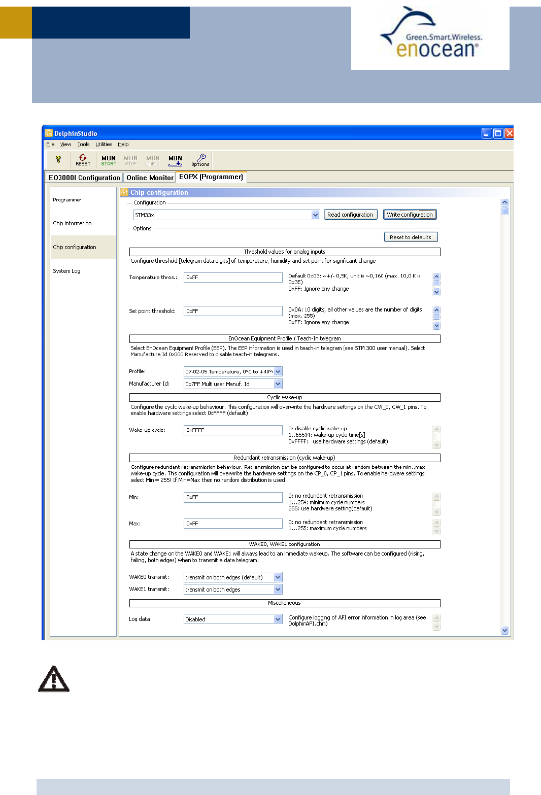
2.7.2 Configuration via serial interface
Via the programming interface the configuration area can be modified. This provides a lot
more configuration options. Values set via serial interface override hardware settings!
These settings are read after RESET or power-on reset only and not at every wake-up of
the module!
The interface is shown in the figure below:
EnOcean provides EOPx (EnOcean Programmer, a command line program) and Dolphin Stu-
dio (Windows application for chip configuration, programming, and testing) and the
USB/SPI programmer device as part of the EDK 300 developer´s kit.
The configuration page of DolphinStudio is shown in the figure below.
Parameter Configuration
via pins Configuration
via serial interface
Wake up cycle See section 2.7.1 Value can be set from 1 s to 65534 s
Redundant
Retransmission cycle
See section 2.7.1 Min…Max values for random interval
If Min=Max -> random switched off
Threshold values for
inputs
(transmission of telegram if
threshold value exceeded)
No The default values are:
Temperature measurement: ±0.5K
Set point measurement: ±10 digits
Edge of wake pin change
causing a telegram trans-
mission
No Every change of a wake pin triggers a wake-up.
For both wake pins it can be configured indi-
vidually if a telegram shall be sent on rising,
falling or both edges.
Manufacturer ID and EEP
(EnOcean Equipment Profile)
No Information about manufacturer and type of
device. This feature is needed for “automatic”
interoperability of sensors and actuators or bus
systems. Unique manufacturer IDs are distrib-
uted by the EnOcean Alliance.
USB <=> SPI
interface SPI
USB
Dolphin Studio, or EOP
Reset
PROG_EN
ADIO7
SCSEDIO0
SCLKDIO1
WSDADIO2
RSDADIO3
STM
330
VDD
GND
USER MANUA
L
V0.60
© 2010 EnOcean | www.enocean.com STM 330 / STM 330C User Manual V0.60 | Page 16
/
27
STM 330 / STM 330C
Please select STM33x and
p
ress “Read confi
g
uration” button before modif
y
in
g
the
entries!

USER MANUA
L
V0.60
© 2010 EnOcean | www.enocean.com STM 330 / STM 330C User Manual V0.60 | Page 17
/
27
STM 330 / STM 330C
2.8 Radio telegram
2.8.1 Normal operation
In normal operation STM 330 transmits telegram data according to the selected EEP (EnO-
cean Equipment Profile).
For details please refer to the EnOcean Equipment Profiles 2.0 specification.
http://www.enocean-alliance.org/fileadmin/redaktion/enocean_alliance/pdf/EnOcean_Equipment_Profiles_2.0.pdf
2.8.2 Teach-in telegram
In case of a wake-up via WAKE1 pin (LRN input) the module transmits a teach-in telegram.
If the manufacturer code is not set, the module transmits a normal telegram according to 2.8.1
with the difference that DI_3=0.
If a manufacturer code is set, this teach-in telegram contains special information as described
below.
With this special teach-in telegram it is possible to identify the manufacturer of a device
and the function and type of a device. The following EnOcean Equipment Profiles are sup-
ported by STM 330. They have to be selected according to the availability of external occu-
pancy button and set point control by the method described in 2.7.2:
07-02-05 Temperature sensor 0-40°C (default)
07-10-03 Temperature sensor 0-40°C, set point control
07-10-05 Temperature sensor 0-40°C, set point, and occupancy control
For details please refer to the EnOcean Equipment Profiles 2.0 specification.
http://www.enocean-alliance.org/fileadmin/redaktion/enocean_alliance/pdf/EnOcean_Equipment_Profiles_2.0.pdf
2.9 Transmit timing
The setup of the transmission timing allows avoiding possible collisions with data packages
of other EnOcean transmitters as well as disturbances from the environment. With each
transmission cycle, 3 identical subtelegrams are transmitted within 40 ms. The transmis-
sion of a subtelegram lasts approximately 1.2 ms. The delay between the three transmis-
sion bursts is affected at random.
USER MANUA
L
V0.60
© 2010 EnOcean | www.enocean.com STM 330 / STM 330C User Manual V0.60 | Page 18
/
27
STM 330 / STM 330C
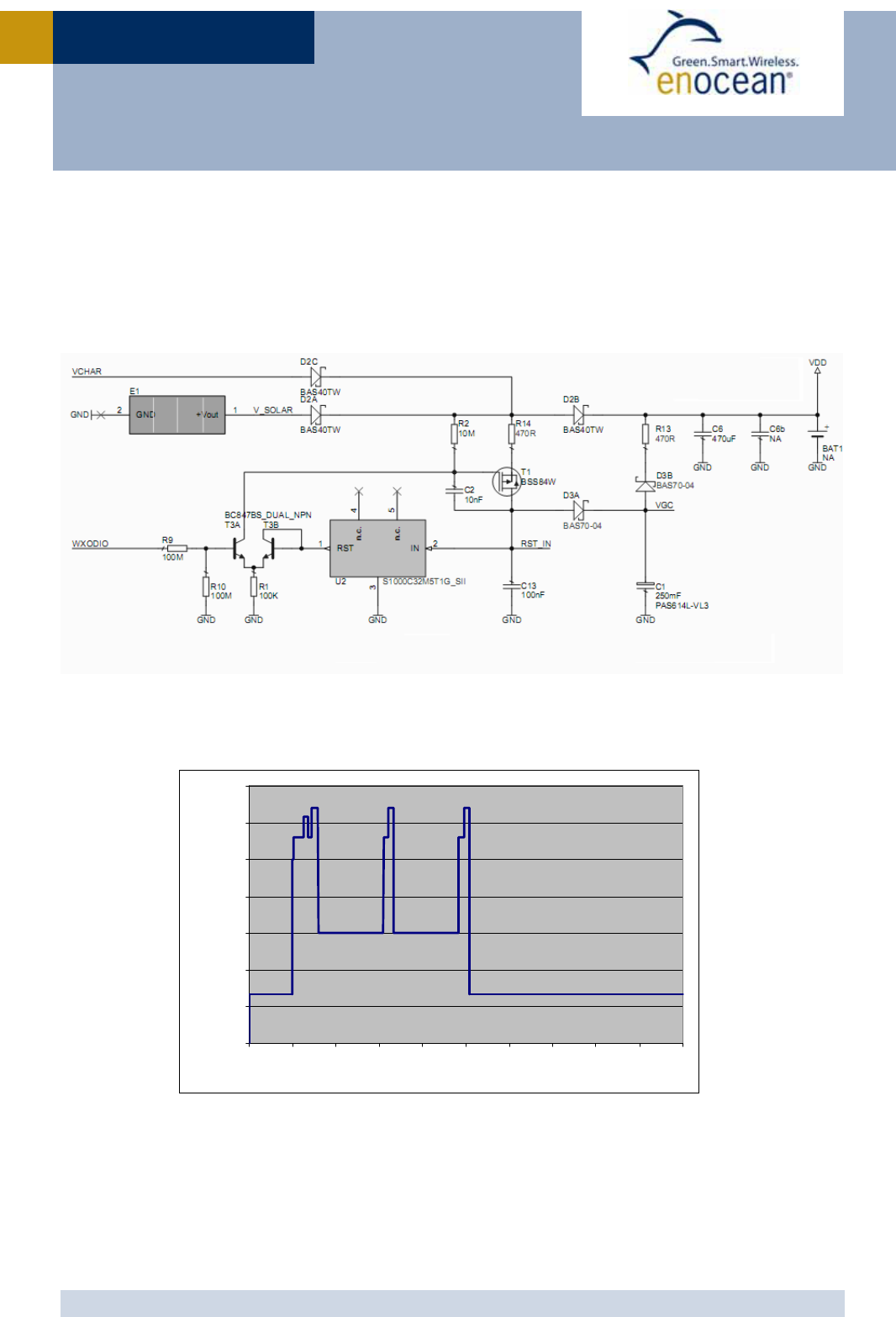
2.10 Charging circuitry
The figure below shows the internal charging circuit. It is controlled via the WXODIO pin of
EO3000I which switches according to the status of the internal threshold detector. For de-
tails please refer to our Dolphin Core Description documentation.
An external 3V battery can be connected at VGC.
2.11 Energy consumption
Current Consumption of STM 33x
Charge needed for one measurement and transmit cycle: ~130 µC
Charge needed for one measurement cycle without transmit: ~30 µC
(current for external sensor circuits not included)
0.00001
0.0001
0.001
0.01
0.1
1
10
100
0 102030405060708090100
Time [ms]
C u rre n t [mA]

USER MANUA
L
V0.60
© 2010 EnOcean | www.enocean.com STM 330 / STM 330C User Manual V0.60 | Page 19
/
27
STM 330 / STM 330C
Calculations are performed on the basis of electric charges because of the internal linear
voltage regulator of the module. Energy consumption varies with voltage of the energy
storage while consumption of electric charge is constant.
From these values the following performance parameters have been calculated:
Wake
cycle
[s] Transmit
interval
Operation Time
in darkness [h]
when storage
fully charged
Required reload
time [h] at 200
lux within 24 h
for continuous
operation
24 h operation
after 6 h
illumination
at x lux
Illumina-
tion level
in lux for
continuous
operation
Current
in µA
required
for con-
tinuous
operation
1 1 0.5 storage too sm all storage too sm all 5220 130.5
1 10 1.7 storage too sm all storage too sm all 1620 40.5
1 100 2.1 storage too sm all storage too sm all 1250 31.3
10 1 5.1 storage too sm all storage too sm all 540 13.5
10 10 16 21 700 175 4.4
10 100 20 16.8 560 140 3.5
100 1 43 7.8 260 65 1.6
100 10 98 3.6 120 30 0.8
100 100 112 3 100 25 0.6
Assumptions:
Internal storage PAS614L-VL3 with 0.25 F, Umax=3.2 V, Umin=2.2 V, T=25 °C
Consumption: Transmit cycle 100 µC, measurement cycle 30 µC
Pre-installed solar cell ECS 300, operating values 3 V and 5 µA @ 200 lux fluorescent
light
Current proportional to illumination level (not true at very low levels!)
These values are calculated values, the accuracy is about +/-20%!
USER MANUA
L
V0.60
© 2010 EnOcean | www.enocean.com STM 330 / STM 330C User Manual V0.60 | Page 20
/
27
STM 330 / STM 330C
3 APPLICATIONS INFORMATION
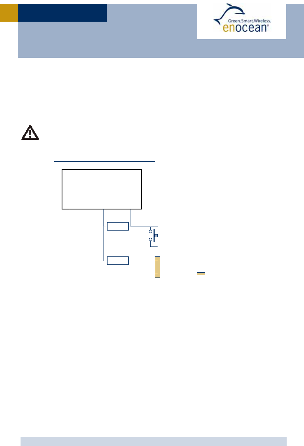
3.1 Using the WAKE pins
The logic input circuits of the WAKE0 and WAKE1 pins are supplied by UVDD and therefore
also usable in “Deep Sleep Mode”. Due to current minimization there is no internal pull-up
or pull-down at the WAKE pins. When STM 330 is in “Deep Sleep Mode” and the logic levels
of WAKE0 and / or WAKE1 is changed, STM 330 starts up.
As the there is no internal pull-up or pull-down at the WAKE0 pin, it has to be en-
sured by external circuitry, that the WAKE0 pin is at a defined logic level at any
time. At time of delivery a jumper is connected between WAKE0 and UVDDext.
WAKE1 provides an internal 1.8MΩ pull-up. See figure below.
When the LRN button is pressed WAKE1 is pulled to GND and a teach-in telegram is trans-
mitted. As long as the button is pressed a small current of approximately 1 µA is flowing. It
is possible to connect an additional external button in parallel between WAKE1 and GND if a
different position of the button in the device is required.
WAKE0 is connected to UVDDext via a jumper at time of delivery. If the module is mounted
onto a host PCB the jumper has to be removed. The circuitry on the host PCB then has to
ensure that WAKE0 is always in a defined position. There are two ways to use WAKE0:
Connect WAKE0 to UVDDext and connect an external button between WAKE0 and GND.
As long as the button is pressed a current of 1 µA will flow.
Connect a 3 terminal switch and switch WAKE0 to either GND or UVDDext. In this case
there is no continuous flow of current in either position of the switch.
EO3000I
WAKE0
WAKE1
UVDD
UVDDext
STM 330
WAKE1
WAKE0
GND
1M8
1M8
LRN Button
Jumper installed at
time of delivery
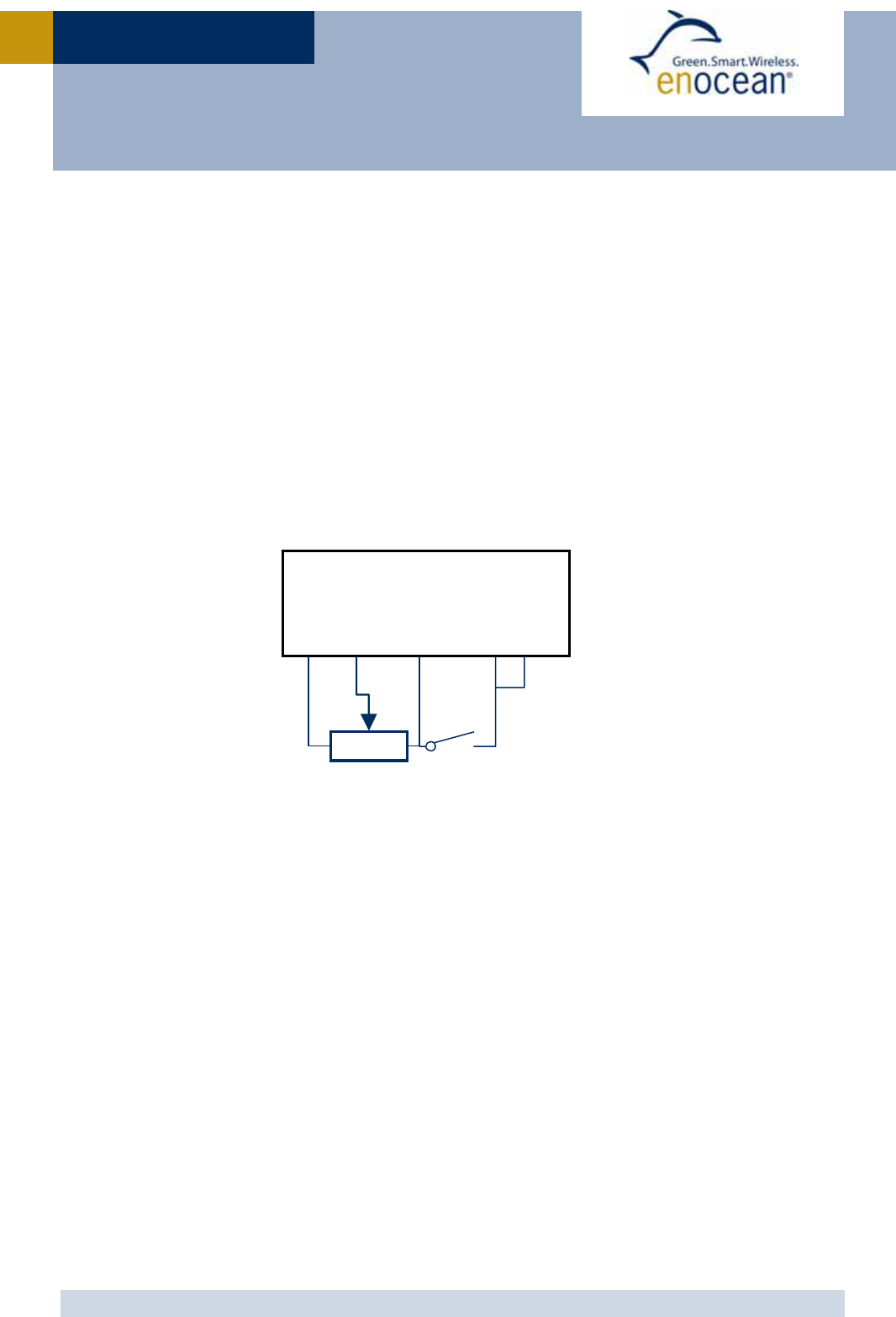
USER MANUA
L
V0.60
© 2010 EnOcean | www.enocean.com STM 330 / STM 330C User Manual V0.60 | Page 21
/
27
STM 330 / STM 330C
3.2 Temperature sensor
STM 330 provides an internal temperature sensor. The sensor is part of the EO3000I IC and
measures the chip temperature. Therefore it is important to provide a good thermal con-
nection of the IC to the environment by ensuring sufficient circulation of air inside the
housing. Only then the measurement will represent the temperature of the environment.
Heating of the chip due to its current consumption is negligible as the chip only consumes
200nA while in sleep mode.
Temperature measurement every second is not recommended as in this case effects of
heating of the chip might become visible.
3.3 Set point control and occupancy button
In order to control the set point, an external potentiometer has to be connected as shown
below. In addition this figure shows how to connect the occupancy button.
STM 330
SWPWR
GND
ADIO0
10k
OCC
UVDDext
Set Point Occupancy

USER MANUA
L
V0.60
© 2010 EnOcean | www.enocean.com STM 330 / STM 330C User Manual V0.60 | Page 22
/
27
STM 330 / STM 330C
3.4 Antenna
3.4.1 Whip antenna
Specification of the whip antenna; L=150 mm @ 315 MHz, L=86 mm @ 868 MHz
Antenna layout recommendation:
STM 330 without host PCB STM 330 with host PCB
Glass, wood, concrete, metal
868MHz: > 2cm
315MHz: > 4cm
868MHz: > 1cm
315MHz: > 2cm
868MHz: > 2cm
315MHz: > 4cm
Host PCB
GND plane

USER MANUA
L
V0.60
© 2010 EnOcean | www.enocean.com STM 330 / STM 330C User Manual V0.60 | Page 23
/
27
STM 330 / STM 330C
3.5 Transmission range
The main factors that influence the system transmission range are type and location of the
antennas of the receiver and the transmitter, type of terrain and degree of obstruction of
the link path, sources of interference affecting the receiver, and “Dead” spots caused by
signal reflections from nearby conductive objects. Since the expected transmission range
strongly depends on this system conditions, range tests should categorically be performed
before notification of a particular range that will be attainable by a certain application.
The following figures for expected transmission range are considered by using a PTM, a
STM or a TCM radio transmitter device and the TCM radio receiver device with preinstalled
whip antenna and may be used as a rough guide only:
Line-of-sight connections: Typically 30 m range in corridors, up to 100 m in halls
Plasterboard walls / dry wood: Typically 30 m range, through max. 5 walls
Line-of-sight connections: Typically 30 m range in corridors, up to 100 m in halls
Ferroconcrete walls / ceilings: Typically 10 m range, through max. 1 ceiling
Fire-safety walls, elevator shafts, staircases and supply areas should be considered as
screening.
The angle at which the transmitted signal hits the wall is very important. The effective wall
thickness – and with it the signal attenuation – varies according to this angle. Signals
should be transmitted as directly as possible through the wall. Wall niches should be
avoided. Other factors restricting transmission range:
Switch mounted on metal surfaces (up to 30% loss of transmission range)
Hollow lightweight walls filled with insulating wool on metal foil
False ceilings with panels of metal or carbon fiber
Lead glass or glass with metal coating, steel furniture
The distance between EnOcean receivers and other transmitting devices such as com-
puters, audio and video equipment that also emit high-frequency signals should be at least
0.5 m
A summarized application note to determine the transmission range within buildings is
available as download from www.enocean.com.
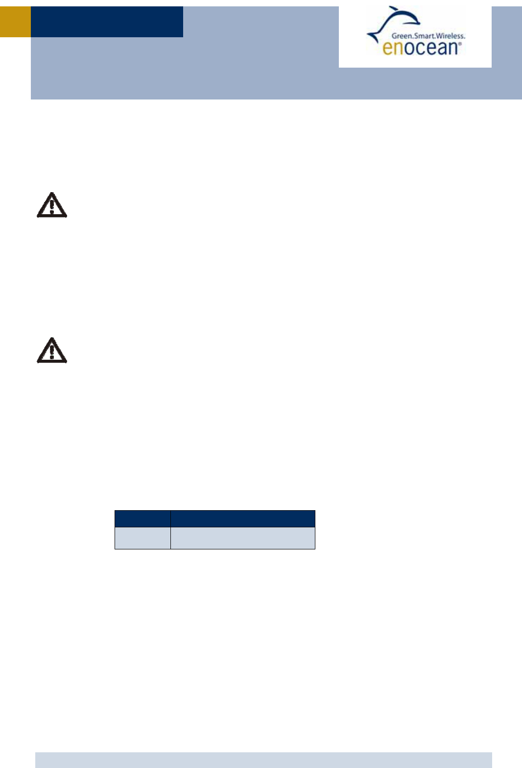
USER MANUA
L
V0.60
© 2010 EnOcean | www.enocean.com STM 330 / STM 330C User Manual V0.60 | Page 24
/
27
STM 330 / STM 330C
4 AGENCY CERTIFICATIONS
The modules have been tested to fulfil the approval requirements for CE (STM 330) and
FCC/IC (STM 330C) based on the built-in firmware.
When developing customer specific firmware based on the API for this module,
special care must be taken not to exceed the specified regulatory limits, e.g. the
duty cycle limitations!
4.1 CE Approval
The STM 330 module bears the EC conformity marking CE and conforms to the R&TTE EU-
directive on radio equipment. The assembly conforms to the European and national re-
quirements of electromagnetic compatibility. The conformity has been proven and the ac-
cording documentation has been deposited at EnOcean. The modules can be operated with-
out notification and free of charge in the area of the European Union and in Switzerland.
EnOcean RF modules must not be modified or used outside their specifica-
tion limits.
EnOcean RF modules may only be used to transfer digital or digitized data.
Analog speech and/or music are not permitted.
EnOcean RF modules must not be used with gain antennas, since this may
result in allowed ERP or spurious emission levels being exceeded.
The final product incorporating EnOcean RF modules must itself meet the
essential requirement of the R&TTE Directive and a CE marking must be af-
fixed on the final product and on the sales packaging each. Operating in-
structions containing a Declaration of Conformity has to be attached.
If the STM 330 transmitter is used according to the regulations of the 868.3
MHz band, a so-called “Duty Cycle” of 1% per hour must not be exceeded.
Permanent transmitters such as radio earphones are not allowed.
The module must be used with only the following approved antenna(s).
Model T
yp
e
STM 330 Pre-installed whip antenna

USER MANUA
L
V0.60
© 2010 EnOcean | www.enocean.com STM 330 / STM 330C User Manual V0.60 | Page 25
/
27
STM 330 / STM 330C
4.2 FCC (United States) certification
STM 330C LIMITED MODULAR APPROVAL
This is an RF module approved for Limited Modular use operating as an intentional trans-
mitting device with respect to 47 CFR 15.231(a-c) and is limited to OEM installation. The
module is optimized to operate using small amounts of harvested energy, such as can be
collected by a small solar cell exposed to ambient light. The module transmits short radio
packets comprised of control signals, (in some cases the control signal may be accompa-
nied with data) such as those used with alarm systems, door openers, remote switches,
and the like. The module does not support continuous streaming of voice, video, or any
other forms of streaming data; it sends only short packets containing control signals and
possibly data and is typically powered by a solar cell in ambient light. The module is de-
signed to comply with, has been tested according to 15.231(a-c), and has been found to
comply with each requirement. Thus, a finished device containing the STM 330C radio mod-
ule can be operated in the United States without additional Part 15 FCC approval (ap-
proval(s) for unintentional radiators may be required for the OEM’s finished product), under
EnOcean’s FCC ID number. This greatly simplifies and shortens the design cycle and devel-
opment costs for OEM integrators.
The module can be triggered manually or automatically, which cases are described below.
Manual Activation
The radio module can be configured to transmit a short packetized control signal if
triggered manually. The module can be triggered, by pressing a switch, for example.
The packet contains one (or more) control signals that is(are) intended to control
something at the receiving end. The packet may also contain data. Depending on
how much energy is available from the energy source, subsequent manual triggers
can initiate the transmission of additional control signals. This may be necessary if
prior packet(s) was (were) lost to fading or interference. Subsequent triggers can
also be initiated as a precaution if any doubt exists that the first packet didn’t arrive
at the receiver. Each packet that is transmitted, regardless of whether it was the
first one or a subsequent one, will only be transmitted if enough energy is available
from the energy source.
Automatic Activation
The radio module also can be configured to transmit a short packetized control sig-
nal if triggered automatically, by a relevant change of its inputs, for example. Again,
the packet contains a control signal that is intended to control something at the re-
ceiving end and may also contain data. As above, it is possible for the packet to get
lost and never reach the receiver. However, if enough energy is available from the
energy source, and the module has been configured to do so, then another packet or
packets containing the control signal may be transmitted at a later, unpredictable
time.

USER MANUA
L
V0.60
© 2010 EnOcean | www.enocean.com STM 330 / STM 330C User Manual V0.60 | Page 26
/
27
STM 330 / STM 330C
OEM Requirements
In order to use EnOcean’s FCC ID number, the OEM must ensure that the following condi-
tions are met.
End users of products, which contain the module, must not have the ability to alter the
firmware that governs the operation of the module. The agency grant is valid only when
the module is incorporated into a final product by OEM integrators.
The end-user must not be provided with instructions to remove, adjust or install the
module.
The Original Equipment Manufacturer (OEM) must ensure that FCC labeling requirements
are met. This includes a clearly visible label on the outside of the final product. Attaching
a label to a removable portion of the final product, such as a battery cover, is not per-
mitted. The label must include the following text:
Contains FCC ID: SZV-STM310C
The enclosed device complies with Part 15 of the FCC Rules. Operation is subject to
the following two conditions: (i.) this device may not cause harmful interference and
(ii.) this device must accept any interference received, including interference that
may cause undesired operation.
When the device is so small or for such use that it is not practicable to place the state-
ment above on it, the information required by this paragraph shall be placed in a promi-
nent location in the instruction manual or pamphlet supplied to the user or, alterna-
tively, shall be placed on the container in which the device is marketed. However, the
FCC identifier or the unique identifier, as appropriate, must be displayed on the device.
The user manual for the end product must also contain the text given above.
Changes or modifications not expressly approved by EnOcean could void the user's au-
thority to operate the equipment.
The OEM must ensure that timing requirements according to 47 CFR 15.231(a-c) are
met.
The OEM must sign the OEM Limited Modular Approval Agreement with EnOcean
The module must be used with only the following approved antenna(s).
Model T
yp
e Gain
STM 330C Pre-installed Wire/Monopole 1.0 dBi

USER MANUA
L
V0.60
© 2010 EnOcean | www.enocean.com STM 330 / STM 330C User Manual V0.60 | Page 27
/
27
STM 330 / STM 330C
4.3 IC (Industry Canada) certification
In order to use EnOcean’s IC number, the OEM must ensure that the following conditions
are met:
Labeling requirements for Industry Canada are similar to those required by the FCC. The
Original Equipment Manufacturer (OEM) must ensure that IC labeling requirements are
met. A clearly visible label on the outside of a non-removable part of the final product
must include the following text:
Contains IC: 5713A-STM310C
The OEM must sign the OEM Limited Modular Approval Agreement with EnOcean