EnOcean STM320U 902.875 MHz transmitter User Manual users manual
EnOcean GmbH 902.875 MHz transmitter users manual
UserManual.wiki
>
EnOcean
>
STM320U User Manual
users manual
Navigation menu
Upload a User Manual
Namespaces
Wiki Guide
HTML
PDF
Info
Views
User Manual
Discussion / Help
Navigation
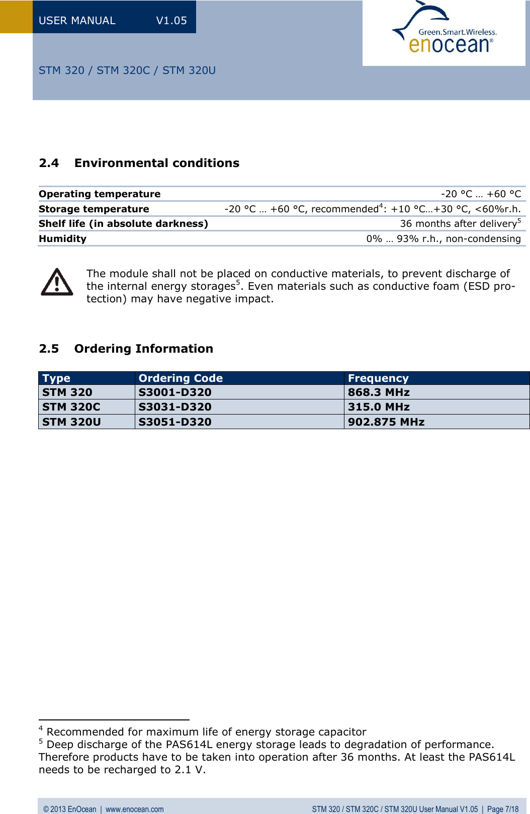
![USER MANUAL V1.05 © 2013 EnOcean | www.enocean.com STM 320 / STM 320C / STM 320U User Manual V1.05 | Page 9/18 STM 320 / STM 320C / STM 320U 3.4 Energy consumption Charge needed for one measurement and transmit cycle: ~80 µC Charge needed for one measurement cycle without transmit: ~10 µC Calculations are performed on the basis of electric charges because of the internal linear voltage regulator of the module. Energy consumption varies with voltage of the energy storage while consumption of electric charge is constant. From these values the following typical performance parameters at room temperature have been calculated: Wake and transmit cycle [s] Operation Time in darkness [h] when storage fully charged Required reload time [h] at 200 lux within 24 h for continuous operation 1500 175 1.8 Assumptions: Internal storage PAS614L-VL3 (after several days of operation at good illumination level) with 0.25 F, Umax=3.2 V, Umin=2.3 V, T=25 °C Consumption: Transmit cycle 80 µC, measurement cycle 10 µC Pre-installed solar cell ECS 300, operating values 3 V and 5 µA @ 200 lux fluorescent light Current proportional to illumination level (not true at very low levels!) These values are calculated, the accuracy is about +/-20%! The performance varies over temperature and may be strongly reduced at extreme temperatures. 0.000010.00010.0010.010.1110100010 20 30 40 50 60 70 80 90 100Time [ms]Current [mA]](https://usermanual.wiki/EnOcean/STM320U/User-Guide-1996766-Page-9.png)