EnOcean TCM515U Transceiver Module User Manual AM11DP ST01 layout
EnOcean GmbH Transceiver Module AM11DP ST01 layout
EnOcean >
Contents
Antenna Chip Layout User Manual
USER MANUAL
TCM 515 – ENOCEAN TRANSCEIVER GATEWAY MODULE
© 2017 EnOcean | www.enocean.com F-710-017, V1.0 TCM 515 User Manual | v1.2 | June 2017 | Page 29/37
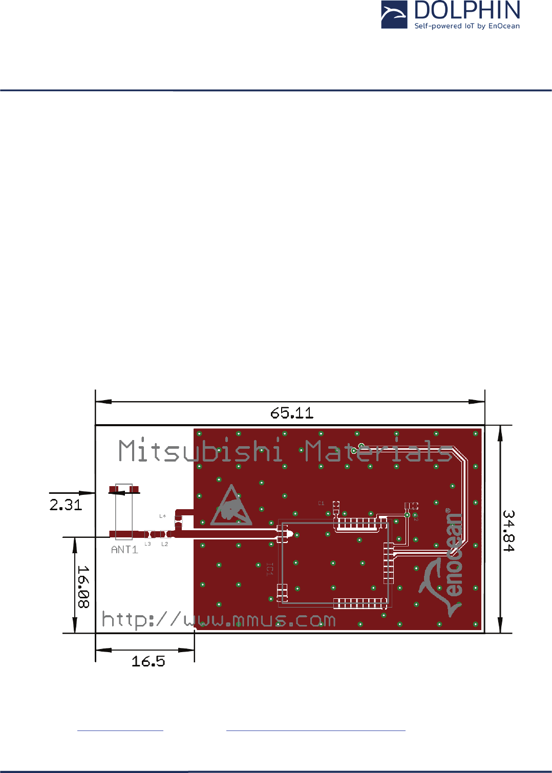
10.2.3 Chip antenna (Supplier: Mitsubishi Material, Type AM11DP-ST01T)
TCM 515 has been certified for use with the chip antenna AM11DP-ST01T from Mitsubishi
Material provided that the following layout guidelines are met:
Dimensions may not be shortened
Matching circuit is part of the limited modular approval and may not be changed
Matching circuits values: L2 = 33 nH; L3 = 3,9 nH, L4 = 12 nH
Use High Q wire wound inductors, e.g. 0603 Murata LQW18A series
Minimum top and bottom side ground plane required as shown below
Connect ground planes using multiple via as shown in Figure 13
Connect matching circuit to RF_50 pin
Figure 13 below shows the reference layout that has to be used.
Figure 13 – Required layout for AM11DG-ST01
For any further questions or chip antenna quotes, please refer to Mitsubishi Materials web-
site at www.mmea.com or email to electroniccomponents@mmus.com.